logging techniques for co saturation & well integrity ... monitoring techniques.pdf ·...
TRANSCRIPT

SchlumbergerPrivate
Logging Techniques for CO2Saturation & Well Integrity Evaluation
Laurent JAMMESIEA-GHG Monitoring Network MelbourneNovember 1st, 2006
2
SchlumbergerPrivate
Schlumberger Carbon Services
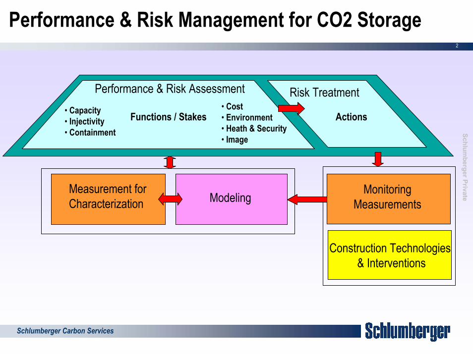
Performance & Risk Management for CO2 Storage
Performance & Risk Assessment• Capacity• Injectivity• Containment
• Cost• Environment• Heath & Security• Image
Functions / Stakes
Risk Treatment
Actions
ModelingMeasurement forCharacterization
Construction Technologies& Interventions
Monitoring Measurements

3
SchlumbergerPrivate
Schlumberger Carbon Services
Monitoring Objectives
Performance Control– Injection efficiency – CO2 in place – displacement & trapping– Sealing
Risk Control– Containment losses– Contamination (shallower aquifers…)– Releases on surface - accumulation
Dynamic modeling calibration for reliable long-term prediction of CO2 fate

4
SchlumbergerPrivate
Schlumberger Carbon Services
Well Monitoring Techniques
CO2 Saturation Measurements– Nuclear– Electrical – Sonic– Sampling
Well Integrity Evaluation– Calipers (corrosion)– Electromagnetic (corrosion)– Sonic (cement)– Ultrasonic (corrosion & cement)

5
SchlumbergerPrivate
Schlumberger Carbon Services
Density Gamma – Gamma( )xexpNoN µρ−⋅= N: counting rate for a detector at a distance x from the source
x: source-detector spacingρ: density
maDfDb ρρρ ⋅Φ−+⋅Φ= )1(ΦD: density porosity
−−
Φ=
2
2
11
COff
bbCOS ρρ
ρρ
Baseline: Measurement:
bρ1bρ
Measurement sensitivity depends on Porosity and formation fluid / CO2 Density contrast
Time-Lapse Density Measurement

6
SchlumbergerPrivate
Schlumberger Carbon Services
Neutron porosity Neutron – Neutron
AmBe SOURCEAmBe SOURCE(4.35 MeV)
NucleusNucleus
ELASTIC NEUTRON SCATTERING The scattering of neutrons by Hydrogen is very efficient in reducing the neutron energy
The Hydrogen Index HI, or quantity of Hydrogen atoms in the pore space, is inferred from detector count rate ratio
Nφ
Coun
t Rat
e (c
ps)
fresh-water-filledporosity sample
Coun
t Rat
e (c
ps)
Coun
t Rat
e (c
ps)
fresh-water-filledporosity sample
N %φNφ
Coun
t Rat
e (c
ps)
NφNφ
Coun
t Rat
e (c
ps)
fresh-water-filledporosity sample
Coun
t Rat
e (c
ps)
Coun
t Rat
e (c
ps)
fresh-water-filledporosity sample
N %φSelectivity to CO2/H2O (brine)Potential Selectivity to CO2/CH4 (ΦN is due to H)
N
NCOS Φ
Φ−= 11
2
Baseline: Measurement:
Time-Lapse Neutron Porosity Measurement
NΦ1NΦ

7
SchlumbergerPrivate
Schlumberger Carbon Services
Neutron Capture Cross-Section Neutron – Gamma
******
RST
NEUTRON ABSORPTION (OR NEUTRON CAPTURE)
Borehole sigma Formation sigmaBorehole sigma Formation sigma
SIGMA: is a measure of how fast the thermal neutrons are captured, which is a process mainly dominated by chlorine.1 11/16”
2 1/2” [chlorine] α [brine]
8
SchlumbergerPrivate
Schlumberger Carbon Services
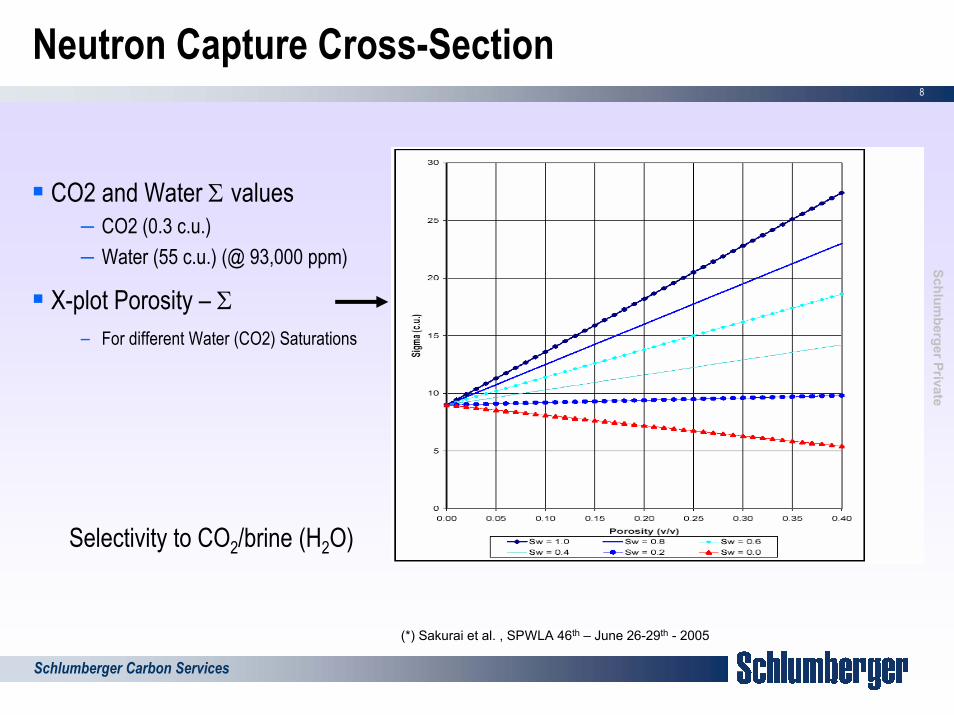
Neutron Capture Cross-Section
CO2 and Water Σ values– CO2 (0.3 c.u.)– Water (55 c.u.) (@ 93,000 ppm)
X-plot Porosity – Σ – For different Water (CO2) Saturations
Selectivity to CO2/brine (H2O)
(*) Sakurai et al. , SPWLA 46th – June 26-29th - 2005

9
SchlumbergerPrivate
Schlumberger Carbon Services
CO2 Monitoring Using RST – Frio Experiment
Injection started on Oct 4th 2004, stopped on Oct 141,600 t/CO2 injected
Target: Frio formation (~5000 ft deep)SandstoneHigh Salinity: 93,000 ppmHigh Porosity: 32-35 p.u.High Permeability: 2.5 Darcy (air)Injector-Monitoring well spacing: 100ft

10
SchlumbergerPrivate
Schlumberger Carbon Services
Monitoring Using RST in Frio – Σ MeasurementCO2 Injection : Start – Oct 4th / Stop - Oct 14th
Time-Lapse CO2 Saturations Time-Lapse Σ Measurements (*) Sakurai et al. , SPWLA 46th – June 26-29th - 2005

11
SchlumbergerPrivate
Schlumberger Carbon Services
Neutron Inelastic Scattering Neutron - Gamma
Nucleus
Nucleus
Inelastic Gamma Rays
Nucleus
Nucleus
Inelastic Gamma Rays
INELASTIC NEUTRON SCATTERING
******2 1/2”
RST
Inelastic Spectra in CO2 and WaterTwo different C/O ratio
– Elemental Yields (accurate but low statistics)– Windows Ratio (less accurate, more precise)
Carbon to Oxygen ratio
Selectivity to CO2/CH4Selectivity to CO2/brine (H2O)Measures CO2 rich-phase and dissolved CO2
1 11/16”

12
SchlumbergerPrivate
Schlumberger Carbon Services
Resistivity
Casing acts like a large electrode.Current returns to surface similarly to a Laterolog tool.Rt = K * ∆V / ∆IFirst step: ∆I = (V1-V2)/RcSecond step: I’ = (V1-V2)/Rc
21
1
12
−=
t
tCO R
RS
Time-Lapse Resistivity Measurement
tR1tR
Baseline: Measurement:
Measurement & Interpretation Issues:Sensitivity to cement resistivityEffect of dissolved CO2 on brine resistivity: CO2 RwEffect of Water in Supercritical CO2
13
SchlumbergerPrivate
Schlumberger Carbon Services
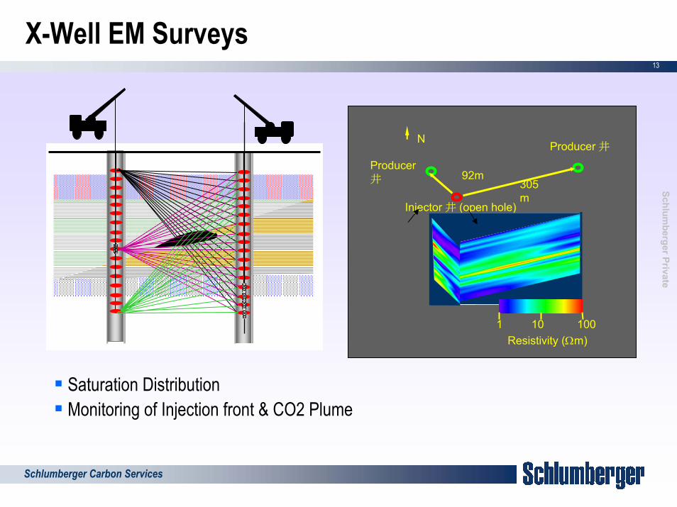
X-Well EM Surveys
Injector 井 (open hole)
Producer井
Producer 井
92m305m
N
1 10010Resistivity (Ωm)
Saturation DistributionMonitoring of Injection front & CO2 Plume

14
SchlumbergerPrivate
Schlumberger Carbon Services
Sonic
BULK MODULUS P-WAVE VELOCITY (VC) DENSITY
∆VP ~ 10 %
Batzle-Wang equations with modified parameters were used for calculations. T = 57oC, P = 6750 psi, [NaCl] = 300 000 ppm(brine)
Selectivity to CO2/brine

15
SchlumbergerPrivate
Schlumberger Carbon Services
Downhole Fluid Analyser – CO2 Concentration
Spectrometer(Gas Analyzer)
Sample Flow
Fluorescence Detector
Lamp
Flowline
Single probemodule
Pumpout module
Multisample module(s)(Six 450cc samples)
OFA/CFA
Packer module H2O and CO2 peaks overlap in the Near-IR region

16
SchlumbergerPrivate
Schlumberger Carbon Services
Well Monitoring Techniques
CO2 Saturation Measurements– Nuclear techniques– Electrical – Sonic– Sampling
Well Integrity Evaluation– Calipers (corrosion)– Electromagnetic (corrosion)– Sonic (cement)– Ultrasonic (corrosion & cement)
17
SchlumbergerPrivate
Schlumberger Carbon Services
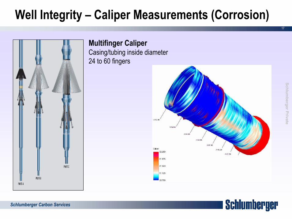
Well Integrity – Caliper Measurements (Corrosion)
Multifinger CaliperCasing/tubing inside diameter24 to 60 fingers

18
SchlumbergerPrivate
Schlumberger Carbon Services
Cement Slurry Displacement Problems

19
SchlumbergerPrivate
Schlumberger Carbon Services
Sonic Cement Bound Evaluation
Ampl
itude

20
SchlumbergerPrivate
Schlumberger Carbon Services
UltraSonic Pulse Echo Imager
The resonance technique

21
SchlumbergerPrivate
Schlumberger Carbon Services
Measurements
CementCementCasingCasingMudMudTransducerTransducer
FormationFormationCementCementCasingCasingMudMudTransducerTransducer
FormationFormation
Echo amplitude
(Internal casing condition)Transit time
Internal radius
Thickness
Cement Impedance
- Internal Casing Condition
- Internal Radius
- Casing Thickness
- Cement Impedance
Tool CharacteristicsCasing OD 4.5 - 13.375 in. Sampling:Casing thickness 0.17 - 0.59 in. (4.5-15 mm) -Azimuthal 5-10 deg.Acoustic Impedance 0-10 Mrayl -Vertical 0.6”- 6”Max. deviation No limit Maximum mud weightLogging speed 400 to 3200 ft/hr - WBM 16 lbm/gal
- OBM 11.6 lbm/gal*(*) Depends on composition, temperature and pressure. Good logs can be obtained in up to 1560 kg/m3 (13 lb/gal) and sometimes up to 1917 kg/m3 (16 lb/gal)

22
SchlumbergerPrivate
Schlumberger Carbon Services
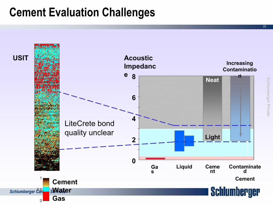
Cement Evaluation Challenges
Discriminate– Cement– Liquid– Gas
Gas
Cement
Liquid
Acoustic Impedance 8
6
4
2
0
Light
Contaminated
Increasing Contaminatio
nNeat
Cement
23
SchlumbergerPrivate
Schlumberger Carbon Services
Cement Evaluation Challenges
Gas
Cement
Liquid
Acoustic Impedance 8
6
4
2
0
Light
Contaminated
Cement
Increasing Contaminatio
nNeat
USIT
LiteCrete bond quality unclear
CementWaterGas

24
SchlumbergerPrivate
Schlumberger Carbon Services
Imaging Behind Casing - principle
Combine USI (ultra sonic imager) measurement:– Excitation of thickness mode of the casing– Single transducer (Tx/Rx)configuration measuring resonance
and decay of thickness mode– Inversion for the acoustic impedance immediately behind the
casing
with FWI (flexural wave imager) measurement:– Excitation of flexural mode of the casing– Pitch-catch configuration (one Tx, two Rx) measuring flexural
attenuation– Due to leakage, image may reveal up to third interface
(formation/double string)

25
SchlumbergerPrivate
Schlumberger Carbon Services
Imaging Behind Casing Flexural Mode
R2
R1Cement
x∆
cmdBFarAmplitudeearAmplitudeNLog
cmx/*
)(20
10
∆
=α
26
SchlumbergerPrivate
Schlumberger Carbon Services
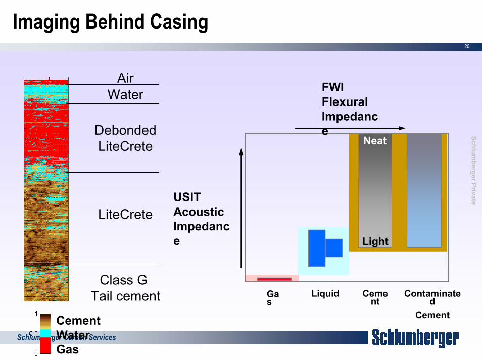
Imaging Behind Casing
CementWaterGas
Class G Tail cement
LiteCrete
DebondedLiteCrete
WaterAir
FWIFlexural Impedanc
Light
Neate
USITAcoustic Impedance
Liquid Contaminated
Cement
Cement
Gas

27
SchlumbergerPrivate
Schlumberger Carbon Services
Example:
Channeled section in LiteCRETE cement
Not identified by USIT and CBL!

28
SchlumbergerPrivate
Schlumberger Carbon Services
Isolation Scanner: Third Interface Echo
• Strong TIE from Flexural Wave
• ∆T independent of T-R Spacing
• ∆T = F(Annulus thickness, Wave Velocity)
Known Velocity Cement Thickness
TIE not always possible:
- Casing Eccentering
- Attenuation of annulus material
- Not enough acoustic contrast
- Large Hole/ Washouts

29
SchlumbergerPrivate
Schlumberger Carbon Services
Conclusion
Wells provide access to the reservoir!
Well measurements complement geophysical monitoring techniques by providing accurate local evaluation of properties
Validation and demonstration of measurement techniques is still needed, which requires tool response characterization in CO2 environment
Availability of wells also allows– Installing permanent sensors (P,T, microseismicity…)– Sampling– Performing X-Well or Well-to-surface surveys

30
SchlumbergerPrivate
Schlumberger Carbon Services
Questions for Designing a Monitoring System
What do I want to monitor? CO2 displacement, leak…What property change can I monitor? P, CO2 Saturation, ResistivityWhat variation am I considering?
What measurement technique can be used? Seismic, EM, Nuclear…What should be my sensor specifications? Accuracy / Precision
Where should I place my sensor? Surface, Obs. Well (Permanent, Logging…)For how long? Operation phase, surveillanceHow can I deploy it?How can I interrogate it?
How can I interpret the measurement?

31
SchlumbergerPrivate
Schlumberger Carbon Services
Questions?