logamatic 4311/4312 control unit - buderus op... · logamatic 4311/4312 control unit. ... buderus...
TRANSCRIPT
6303 1852 – 02/2006 GB For the user
Operating instructions
Logamatic 4311/4312 control unit
Please read thoroughly before use.
Overview
About these instructions
These operating instructions contain important information for the safe and correct operation of the Logamatic 4311 and 4312 control units.
This unit meets all requirements of relevant European standards directives and guidelines.
Its conformity has been verified. All associated documents and the original Declaration of Conformity are available from Buderus.
2 Operating instructions Logamatic 4311/4312 control devices • Issue 02/2006
We reserve the right to make any changes due to technical modifications.
Subject to technical modifications.
Constant development may lead to minor deviations in the illustrations, procedures and specifications described/shown.
Updating your documentation
Please let us know if you have any suggestions which would improve our documentation or if you have noticed any errors.
Content
3
We reserve the right to make any changes due to technical modifications.
Operating instructions Logamatic 4311/4312 control devices • Issue 02/2006
1 Introduction. . . . . . . . . . . . . . . . . . . . . . . . . . . . . . . . . . . . . . . . . . . . . . . . .4
2 For your safety . . . . . . . . . . . . . . . . . . . . . . . . . . . . . . . . . . . . . . . . . . . . . .5
3 Tips on energy-efficient heating . . . . . . . . . . . . . . . . . . . . . . . . . . . . . . . . .7
4 Controls . . . . . . . . . . . . . . . . . . . . . . . . . . . . . . . . . . . . . . . . . . . . . . . . . . .8
5 Modules and their functions . . . . . . . . . . . . . . . . . . . . . . . . . . . . . . . . . . . .9
6 MEC 2 programmer . . . . . . . . . . . . . . . . . . . . . . . . . . . . . . . . . . . . . . . . . . 15
7 Getting started . . . . . . . . . . . . . . . . . . . . . . . . . . . . . . . . . . . . . . . . . . . . . 16
8 Setting the room temperature . . . . . . . . . . . . . . . . . . . . . . . . . . . . . . . . . . 19
9 DHW (Domestic Hot Water) control. . . . . . . . . . . . . . . . . . . . . . . . . . . . . . 23
10 DHW circulation pump control . . . . . . . . . . . . . . . . . . . . . . . . . . . . . . . . . 25
11 Calling up displays . . . . . . . . . . . . . . . . . . . . . . . . . . . . . . . . . . . . . . . . . . 27
12 Selecting the standard program . . . . . . . . . . . . . . . . . . . . . . . . . . . . . . . . 28
13 Changing a program . . . . . . . . . . . . . . . . . . . . . . . . . . . . . . . . . . . . . . . . . 32
14 Creating a new heating program. . . . . . . . . . . . . . . . . . . . . . . . . . . . . . . . 42
15 Entering a new DHW program. . . . . . . . . . . . . . . . . . . . . . . . . . . . . . . . . . 44
16 Entering a new DHW secondary circulation pump program . . . . . . . . . . . 45
17 Party/Pause function. . . . . . . . . . . . . . . . . . . . . . . . . . . . . . . . . . . . . . . . . 46
18 Holiday program . . . . . . . . . . . . . . . . . . . . . . . . . . . . . . . . . . . . . . . . . . . . 48
19 Setting summer/winter changeover . . . . . . . . . . . . . . . . . . . . . . . . . . . . . 51
20 Changing the standard display . . . . . . . . . . . . . . . . . . . . . . . . . . . . . . . . . 54
21 Entering date and time . . . . . . . . . . . . . . . . . . . . . . . . . . . . . . . . . . . . . . . 55
22 Flue gas test . . . . . . . . . . . . . . . . . . . . . . . . . . . . . . . . . . . . . . . . . . . . . . . 57
23 Matching the room temperature sensor . . . . . . . . . . . . . . . . . . . . . . . . . . 58
24 Operating tips for cascade systems . . . . . . . . . . . . . . . . . . . . . . . . . . . . . 59
25 Automatic maintenance message . . . . . . . . . . . . . . . . . . . . . . . . . . . . . . . 60
26 Troubleshooting . . . . . . . . . . . . . . . . . . . . . . . . . . . . . . . . . . . . . . . . . . . . 61
27 Emergency mode . . . . . . . . . . . . . . . . . . . . . . . . . . . . . . . . . . . . . . . . . . . 63
28 Setup report . . . . . . . . . . . . . . . . . . . . . . . . . . . . . . . . . . . . . . . . . . . . . . . 65
29 Keyword Index . . . . . . . . . . . . . . . . . . . . . . . . . . . . . . . . . . . . . . . . . . . . . 66
4 Operating instructions Logamatic 4311/4312 control devices • Issue 02/2006
We reserve the right to make any changes due to technical modifications.
Introduction1
1 Introduction
Logamatic 4311 and Logamatic 4312 control units are designed for modular applications and will, subject to type and extent of the system, be equipped with up to four additional function modules.The modular design enables, with a full compliment of equipment, the connection of up to eight heating circuits with mixing valves.
The modules include controls for manual operation and operating displays.
Logamatic 4311 and Logamatic 4312 has a safety function built in to the unit.
The basic equipment level of Logamatic 4311 comprises:
Weather-compensated control of one boiler
Use of single stage, two stage or modulating burner
Boiler control unit
MEC 2 programmer
The basic equipment level of Logamatic 4312 comprises:
Weather-compensated control of one boiler
Use of single stage, two stage or modulating burner
Boiler control unit
Boiler display for indicating the boiler temperature
The MEC 2 programmer is the central control unit.
Functions and operating setting are shown in the display.
The buttons enable functions to be called up. If you push a button and hold it down, you can change the respective setting using the dial.
The new value will be accepted and stored after you release the button.
The unit automatically returns to the standard display, if no entry is detected within approx. 5 min.
The Logamatic 4311 and Logamatic 4312 control units offer the following functions, subject to the function modules which have been fitted:
10-channel timer with weekly program
Automatic time adjustment from a radio clock signal (This feature does not function in the UK and Eire and should be switched off)
Automatic adjustments between summer and winter
Domestic Hot Water (DHW) production 30 minutes before heating operation
Domestic hot water priority
Holiday program
Frost protection
8 standard programs for selection. You can also create your own personal program, if none of the above programs meet your requirements.
Run-on time for heating circuit pump and DHW cylinder loading pump 3 minutes, subject to operating conditions
Protection against condensate
Flue gas test
Automatic adoption of heating curve
Self-learning start-up and switch-off optimisation
Selection between external and room temperature control
For your safety 2
2 For your safety
2.1 Correct use
The Logamatic 4311 and 4312 control units are only intended to control heating systems in lager houses, public and commercial properties.
2.2 Please observe these notes
Only operate the control units as intended and when they are in perfect working order.
Arrange for your heating engineer to instruct you in the correct operation of the system.
Read these operating instructions carefully.
Only enter or change the operating settings specified in these instructions. Other inputs affect the heating system control programs and can lead to system malfunctions.
Maintenance, repairs and fault diagnosis should only be carried out by authorised and qualified personnel.
WARNING!
RISK TO LIFE
from electric shock.
Never open the control unit.
In an emergency isolate the heating system from the mains supply using the emergency stop switch located outside the boiler room or by removing the main fuse.
Arrange for your installer to rectify immediately any faults in your heating system.
WARNING!
RISK OF SCALDING
For thermal disinfection purposes, the entire DHW system is set in the factory to heat up to 70°C (activated: Tuesday night at 01:00).
If required (e.g. shift work), your heating installer can alter the activation time.
If the DHW circuit of your heating system is not equipped with a thermostatic valve, do not open any hot water tap without mixing in some cold water.
As there is a risk of scalding at temperatures above approximately 60°C, ask your heating installer what temperature the hot water has been set to.
CAUTION!
SYSTEM DAMAGE
through frost.The heating system can freeze up if it is out of use, e.g. through a shutdown because of fault(s).
Leave the heating system switched ON all the time.
Contact your heating installer if a fault occurs.
5
We reserve the right to make any changes due to technical modifications.
Operating instructions Logamatic 4311/4312 control devices • Issue 02/2006
For your safety2
2.3 Cleaning the control unit
The control unit should only be cleaned with a damp cloth.
2.4 Disposal
Dispose of the control unit packaging in an environmentally responsible manner.
The lithium battery in the CM431 module may only be replaced by your installer.
6 Operating instructions Logamatic 4311/4312 control devices • Issue 02/2006
We reserve the right to make any changes due to technical modifications.

Tips on energy-efficient heating 3
7
We reserve the right to make any changes due to technical modifications.
Operating instructions Logamatic 4311/4312 control devices • Issue 02/2006
3 Tips on energy-efficient heating
Buderus control units ensure optimum comfort and many technical options, as well as energy savings and simple operation.
Observing the following tips you could save energy, money and protect the environment.
Ask your installer to instruct you in the correct use of this equipment during commissioning. If in doubt, ask.
Read the operating instructions for your heating system thoroughly.
Have your system adjusted to the conditions of your property.
Have your heating system regularly serviced.
During the cold season air rooms, but only for short periods, this prevents rooms getting too cold.
Check the settings of thermostatic radiator settings in each room.
Never set the temperature of living accommodation or domestic hot water higher than necessary.
Do the pre-set switching times (day and night setback operation) for central heating and domestic hot water heating, meet your life-style requirements?
Adjust the standard program to meet your requirements. Utilise the setting options to change over between summer and winter.
Avoid making frequent changes to the temperature settings for accommodation and domestic hot water heating.
All temperature adjustments take time to take effect. Only change any adjustments you have made the next day, if your previous modifications have failed to provide the desired result.
A pleasant atmosphere not only depends on the room temperature, but also the relative humidity: the drier a room, the cooler it feels. You can improve the relative humidity with houseplants.
Controls4
8 Operating instructions Logamatic 4311/4312 control devices • Issue 02/2006
We reserve the right to make any changes due to technical modifications.
4 Controls
The Logamatic 4312 control unit is generally operated in the same way as the Logamatic 4311 control unit.The following therefore makes no explicit reference to Logamatic 4312.
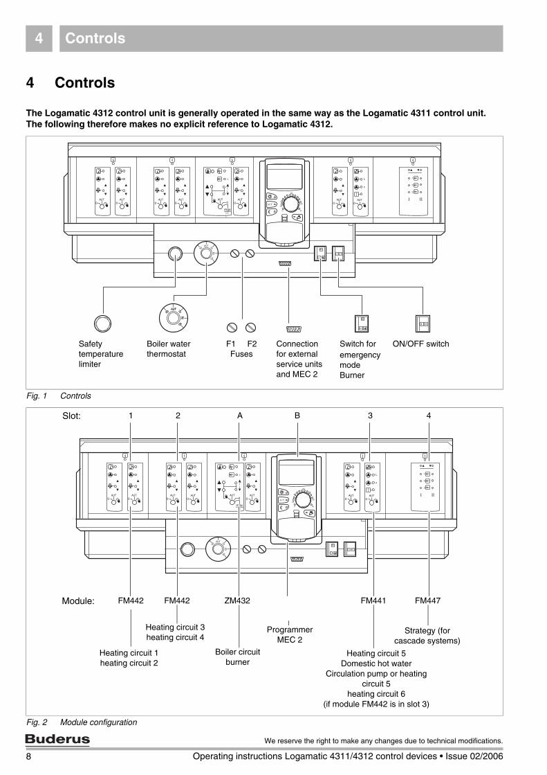
Fig. 1 Controls
Fig. 2 Module configuration
Boiler waterthermostat
F1 F2Fuses
Connectionfor externalservice unitsand MEC 2
Switch foremergency modeBurner
ON/OFF switchSafetytemperaturelimiter
Slot: A B 3
Module: FM442 FM442
Heating circuit 3 heating circuit 4
Heating circuit 5Domestic hot water
Circulation pump or heating circuit 5
heating circuit 6(if module FM442 is in slot 3)
1 2 4
ZM432 FM441 FM447
Heating circuit 1heating circuit 2
Strategy (forcascade systems)
Boiler circuitburner
Programmer MEC 2
Modules and their functions 5
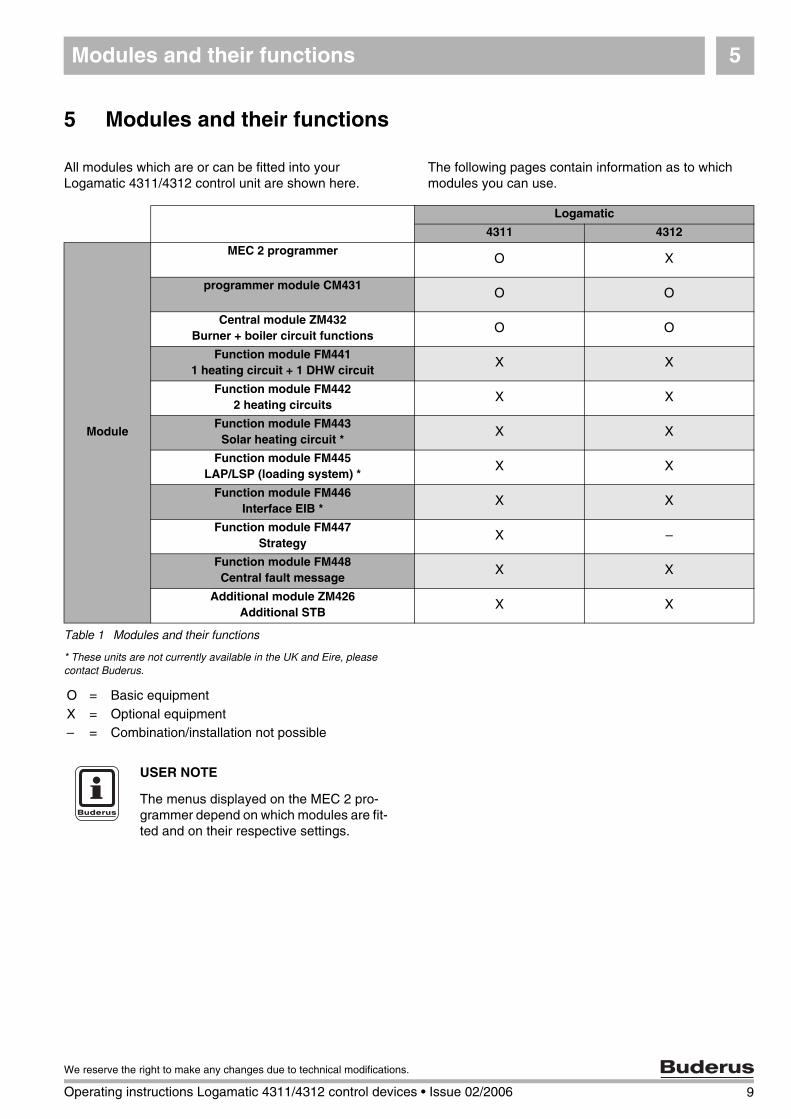
5 Modules and their functions
The following pages contain information as to which modules you can use.
All modules which are or can be fitted into your Logamatic 4311/4312 control unit are shown here.
* These units are not currently available in the UK and Eire, please contact Buderus.
Logamatic
4311 4312
Module
MEC 2 programmerO X
programmer module CM431O O
Central module ZM432Burner + boiler circuit functions
O O
Function module FM4411 heating circuit + 1 DHW circuit
X X
Function module FM4422 heating circuits
X X
Function module FM443Solar heating circuit *
X X
Function module FM445LAP/LSP (loading system) *
X X
Function module FM446Interface EIB *
X X
Function module FM447Strategy
X –
Function module FM448Central fault message
X X
Additional module ZM426Additional STB
X X
Table 1 Modules and their functions
O = Basic equipmentX = Optional equipment– = Combination/installation not possible
USER NOTE
The menus displayed on the MEC 2 pro-grammer depend on which modules are fit-ted and on their respective settings.
9
We reserve the right to make any changes due to technical modifications.
Operating instructions Logamatic 4311/4312 control devices • Issue 02/2006
Modules and their functions5
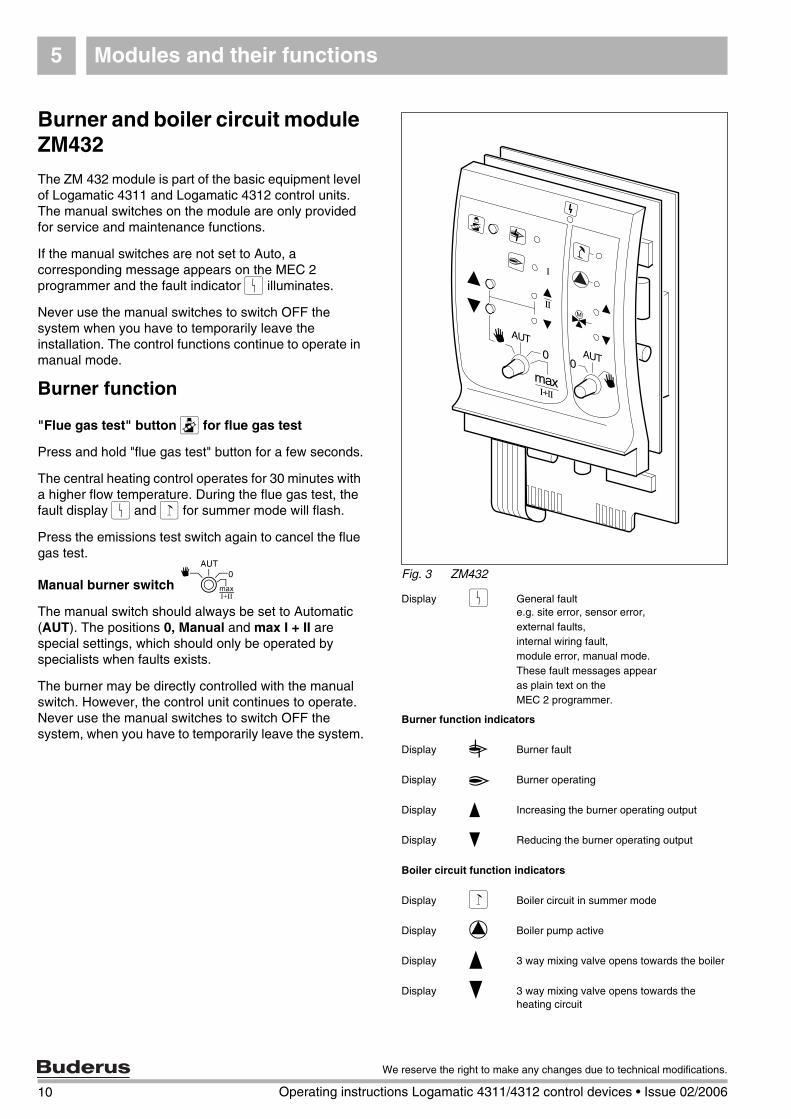
Burner and boiler circuit module ZM432
The ZM 432 module is part of the basic equipment level of Logamatic 4311 and Logamatic 4312 control units.The manual switches on the module are only provided for service and maintenance functions.
If the manual switches are not set to Auto, a corresponding message appears on the MEC 2 programmer and the fault indicator 0 illuminates.
Never use the manual switches to switch OFF the system when you have to temporarily leave the installation. The control functions continue to operate in manual mode.
Burner function
"Flue gas test" button Q for flue gas test
Press and hold "flue gas test" button for a few seconds.
The central heating control operates for 30 minutes with a higher flow temperature. During the flue gas test, the fault display 0 and 1 for summer mode will flash.
Press the emissions test switch again to cancel the flue gas test.
Manual burner switch ]The manual switch should always be set to Automatic (AUT). The positions 0, Manual and max I + II are special settings, which should only be operated by specialists when faults exists.
The burner may be directly controlled with the manual switch. However, the control unit continues to operate. Never use the manual switches to switch OFF the system, when you have to temporarily leave the system.
Fig. 3 ZM432
Display 0 General faulte.g. site error, sensor error,external faults, internal wiring fault,module error, manual mode.These fault messages appearas plain text on theMEC 2 programmer.
Burner function indicators
Display 9 Burner fault
Display A Burner operating
Display U Increasing the burner operating output
Display V Reducing the burner operating output
Boiler circuit function indicators
Display 1 Boiler circuit in summer mode
Display 8 Boiler pump active
Display U 3 way mixing valve opens towards the boiler
Display V 3 way mixing valve opens towards the heating circuit
10 Operating instructions Logamatic 4311/4312 control devices • Issue 02/2006
We reserve the right to make any changes due to technical modifications.
Modules and their functions 5
Boiler circuit function
Manual boiler circuit switchBThe manual switch should always be set to AUT. The positions 0 and Manual are special settings, which should only be operated by installers in case of errors.
3: Only the first stage will be enabled for single and two stage burners. For modulating burners, the burner output can be infinitely increased using 5 and infinitely reduced using 6.
AUT: The burner operates in automatic mode.
0: The burner is switched OFF. Except when the burner emergency mode switch is set to 4.
Max I+II: The burner continuously operates at maximum output.
3: Any installed boiler pump will be switched ON.The boiler circuit valve can be manually operated.
AUT: The boiler circuit operates in automatic mode.
0: Any installed boiler pump will be switched OFF.The boiler circuit valve can be manually operated.Current functions are displayed by LED´s.
11
We reserve the right to make any changes due to technical modifications.
Operating instructions Logamatic 4311/4312 control devices • Issue 02/2006
Modules and their functions5
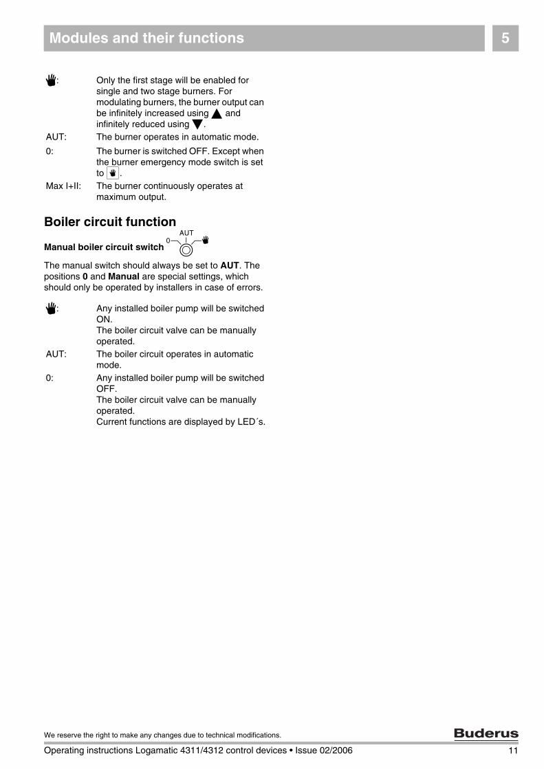
Heating circuit and DHW module FM441
The FM441 function module controls one heating circuit with valve plus one DHW circuit with circulation pump. One module per control unit may be installed in any slot.
The manual switches on the module are only provided for service and maintenance functions.
If the manual switch B is not set to automatic, a corresponding message appears on the MEC 2 and the fault indicator 0 illuminates.
Never use the manual switches to switch OFF the system when you have to temporarily leave the installation.
The control functions continue to operate in manual mode.
Heating circuit function
Manual switch for heating circuit B
DHW function
Manual switch for DHW heating B
Fig. 4 FM441
Display 0 General faulte.g. site error, sensor error,external faults,internal wiring faultmodule error, manual mode.These fault messages appearas plain text on theMEC 2 programmer.
Heating circuit function indicators
Display 1 Heating circuit in summer mode
Display 8 Heating circuit pump active
Display U 3 way mixing valve opens
Display V 3 way mixing valve closes
Indicators for DHW functions
Display X DHW stays cold
Display 8 L DHW Cylinder loading pump active
Display Z Thermal disinfection active. Risk of scalding!
Display 8 Z DHW circulation pump active
3: The heating circuit pump is switched ON. The heating circuit valve can be manually operated.
AUT: The heating circuit operates in automatic mode.
0: Only the heating circuit pump is switched OFF. The control functions continue to operate.
3: The DHW loading pump is switched ON.
AUT: The DHW circuit operates in automatic mode.
0: Only the DHW loading pump is switched OFF. The control functions continue to operate.
12 Operating instructions Logamatic 4311/4312 control devices • Issue 02/2006
We reserve the right to make any changes due to technical modifications.
Modules and their functions 5
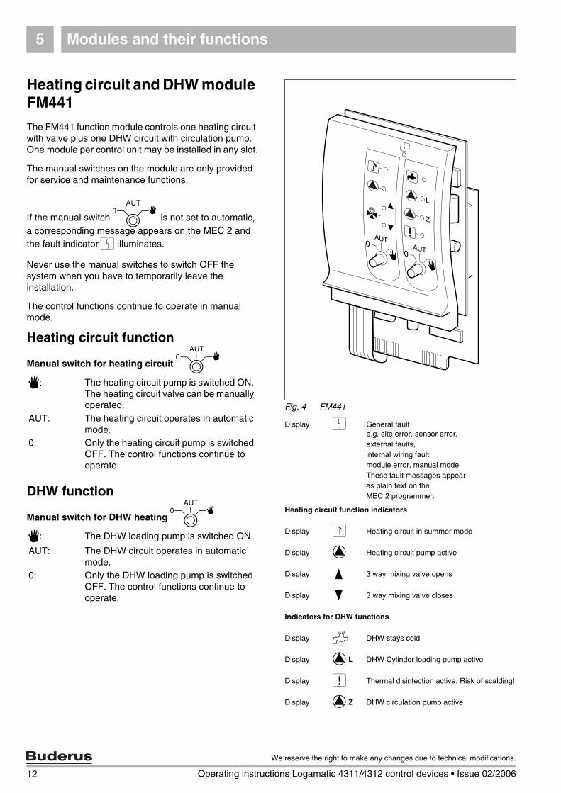
Heating circuit module FM442
The FM442 function module controls two independent heating circuits with valve.
Each control unit can accommodate up to four such modules.
The manual switches on the module are only provided for service and maintenance functions.
If the manual switch B is not set to automatic, a corresponding message appears on the MEC 2 and the fault indicator 0 illuminates.
Never use the manual switches to switch OFF the system when you have to temporarily leave the installation. The control functions continue to operate in manual mode.
Heating circuit function 1 + 2
Manual switch – heating circuit B
Fig. 5 FM442
Display 0 General faulte.g. site error, sensor error,external faults,internal wiring faultmodule error, manual mode.These fault messages appearas plain text on theMEC 2 programmer.
Heating circuit function indicators
Display 1 Heating circuit in summer mode
Display 8 Heating circuit pump active
Display U 3 way mixing valve opens
Display V 3 way mixing valve closes
3: The heating circuit pump is switched ON. The heating circuit valve can be manually operated.
AUT: The heating circuit operates in automatic mode.
0: Only the heating circuit pump is switched OFF. The control functions continue to operate.
13
We reserve the right to make any changes due to technical modifications.
Operating instructions Logamatic 4311/4312 control devices • Issue 02/2006
Modules and their functions5
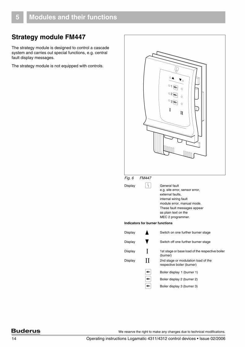
Strategy module FM447
The strategy module is designed to control a cascade system and carries out special functions, e.g. central fault display messages.
The strategy module is not equipped with controls.
Fig. 6 FM447
Display 0 General faulte.g. site error, sensor error,external faults,internal wiring faultmodule error, manual mode.These fault messages appearas plain text on theMEC 2 programmer.
Indicators for burner functions
Display U Switch on one further burner stage
Display V Switch off one further burner stage
Display [ 1st stage or base load of the respective boiler (burner)
Display \ 2nd stage or modulation load of the respective boiler (burner)
a Boiler display 1 (burner 1)
a Boiler display 2 (burner 2)
a Boiler display 3 (burner 3)
14 Operating instructions Logamatic 4311/4312 control devices • Issue 02/2006
We reserve the right to make any changes due to technical modifications.
MEC 2 programmer 6
15
We reserve the right to make any changes due to technical modifications.
Operating instructions Logamatic 4311/4312 control devices • Issue 02/2006
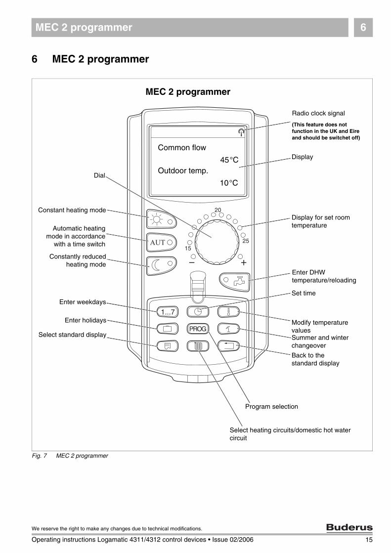
6 MEC 2 programmer
Fig. 7 MEC 2 programmer
Common flow
Outdoor temp.45°C
10°C
Constant heating mode
Dial
Automatic heatingmode in accordance
with a time switch
Constantly reducedheating mode
Enter weekdays
Enter holidays
Select standard display
Radio clock signal
(This feature does not function in the UK and Eire and should be switchet off)
Display
Display for set room temperature
Enter DHW temperature/reloading
Set time
Modify temperature valuesSummer and winter changeover
Back to thestandard display
Program selection
Select heating circuits/domestic hot water circuit
MEC 2 programmer
Getting started7
7 Getting started
Initial start-up
Check that all manual switches on the programmer and the modules used are set to AUT.
Set the control unit ON/OFF switch to R.
The MEC2 programmer will then start up. Data is then matched between the control unit and the MEC2. A little later, the display of the MEC2 programmer indicates the standard display preset at the factory.
Shutting down
Set the ON/OFF switch to T.
In an emergency, switch OFF the emergency stop switch outside the boiler area.
Setting the room temperature for all heating circuits allocated to the MEC 2
Setting the day room temperature
Press and release the E button whilst the cover is closed.
Turn the dial until the required day room temperature is displayed.
Press the D button.
Night room temperature
Press and release the E button whilst the cover is closed.
Turn the dial until the required night setback room temperature is displayed.
Press the D button.
USER NOTE
– Heating circuits with the MEC 2 pro-grammer are selected as "MEC heat. circ.".
– Heating circuits without MEC 2 pro-grammer are selected as "Heating cir-cuit and heating circuit number" or as "Heating circuit name and heating cir-cuit number".
16 Operating instructions Logamatic 4311/4312 control devices • Issue 02/2006
We reserve the right to make any changes due to technical modifications.
Getting started 7
Setting the room temperature for heating circuits without an individual remote control unit
Heating circuits are not allocated to the MEC 2.
Setting the day room temperature
Press and hold down the C button.
Turn the dial until the required heating circuit is displayed.
Release the C button.
Press and hold down the E button.
Turn the dial until the required day room temperature is displayed.
Release the E button.
Press the D button.
Setting the night room temperature
Press and hold down the C button.
Turn the dial until the required heating circuit is displayed.
Release the C button.
Press and hold down the F button.
Turn the dial until the required night setback room temperature is displayed.
Release the F button.
Press the D button.
Setting the room temperature for heating circuits equipped with different remote control units
See separate operating instructions for the relevant remote control.
Set the DHW temperature
Press and hold down the I button.
Turn the dial until the required DHW temperature is displayed.
Release the I button.
17
We reserve the right to make any changes due to technical modifications.
Operating instructions Logamatic 4311/4312 control devices • Issue 02/2006
Getting started7
Setting the summer / winter changeover
You must select the required heating circuit before calling up the summer/winter changeover. You may select either an individual heating circuit or all circuits allocated to the MEC 2.
Press and hold down the C button.
Turn the dial until the required heating circuit is displayed.
Release the C button.
Press and hold down the H button.
Turn the dial until the outside temperature is displayed, below which heating should commence.
Release the H button.
Change operating condition
With the cover closed, the operating conditions of those heating circuits are changed, which have been allocated to the MEC 2.
Press and release the E button with the cover closed.The system provides constant heat at the set day room temperature.
Press and release the F button with the cover closed.The system operates constantly in set back heating mode.
Press and release the D button with the cover closed.
The system operates automatically according to the set switching program.
18 Operating instructions Logamatic 4311/4312 control devices • Issue 02/2006
We reserve the right to make any changes due to technical modifications.
Setting the room temperature 8
8 Setting the room temperature
for all heating circuits allocated to the MEC 2
During the installation, your installer will determine, which heating circuits must be controlled by the MEC 2 programmer. These heating circuits are referred to as "MEC heat. circ.". You set the room temperature for "MEC heat. circ." with the dial.
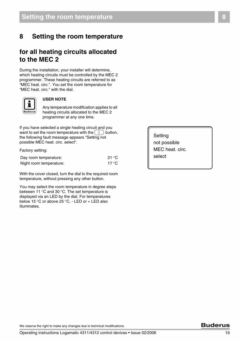
If you have selected a single heating circuit and you want to set the room temperature with the G button, the following fault message appears "Setting not possible MEC heat. circ. select".
Factory setting:
With the cover closed, turn the dial to the required room temperature, without pressing any other button.
You may select the room temperature in degree steps between 11 °C and 30 °C. The set temperature is displayed via an LED by the dial. For temperatures below 15 °C or above 25 °C, - LED or + LED also illuminates.
USER NOTE
Any temperature modification applies to all heating circuits allocated to the MEC 2 programmer at any one time.
Settingnot possibleMEC heat. circ.selectDay room temperature: 21 °C
Night room temperature: 17 °C
19
We reserve the right to make any changes due to technical modifications.
Operating instructions Logamatic 4311/4312 control devices • Issue 02/2006
Setting the room temperature8
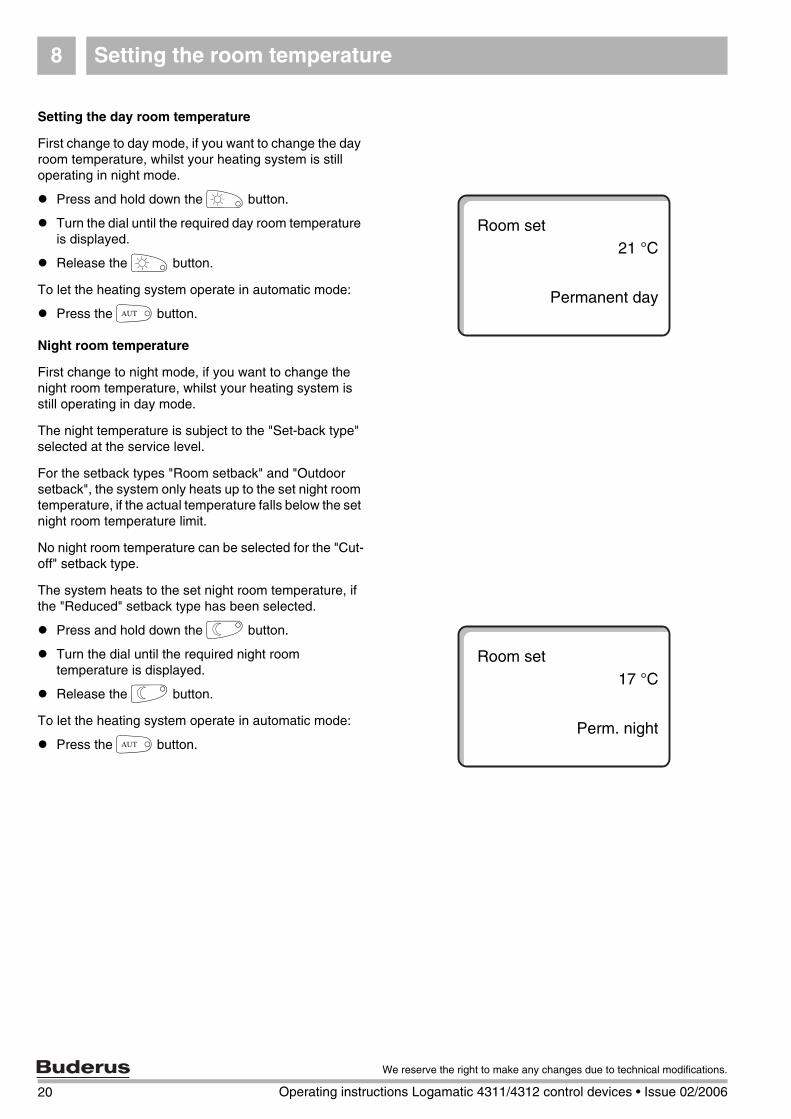
Setting the day room temperature
First change to day mode, if you want to change the day room temperature, whilst your heating system is still operating in night mode.
Press and hold down the E button.
Turn the dial until the required day room temperature is displayed.
Release the E button.
To let the heating system operate in automatic mode:
Press the D button.
Night room temperature
First change to night mode, if you want to change the night room temperature, whilst your heating system is still operating in day mode.
The night temperature is subject to the "Set-back type" selected at the service level.
For the setback types "Room setback" and "Outdoor setback", the system only heats up to the set night room temperature, if the actual temperature falls below the set night room temperature limit.
No night room temperature can be selected for the "Cut-off" setback type.
The system heats to the set night room temperature, if the "Reduced" setback type has been selected.
Press and hold down the F button.
Turn the dial until the required night room temperature is displayed.
Release the F button.
To let the heating system operate in automatic mode:
Press the D button.
Room set21 °C
Permanent day
Room set17 °C
Perm. night
20 Operating instructions Logamatic 4311/4312 control devices • Issue 02/2006
We reserve the right to make any changes due to technical modifications.
Setting the room temperature 8
Setting the room temperature for heating circuits without remote control
For all heating circuits, to which no remote control was allocated during the installation, the room temperature is set as follows:
Open the cover.
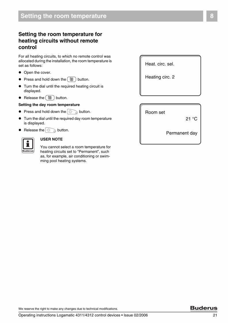
Press and hold down the C button.
Turn the dial until the required heating circuit is displayed.
Release the C button.
Setting the day room temperature
Press and hold down the E button.
Turn the dial until the required day room temperature is displayed.
Release the E button.
Heat. circ. sel.
Heating circ. 2
Room set21 °C
Permanent dayUSER NOTE
You cannot select a room temperature for heating circuits set to "Permanent", such as, for example, air conditioning or swim-ming pool heating systems.
21
We reserve the right to make any changes due to technical modifications.
Operating instructions Logamatic 4311/4312 control devices • Issue 02/2006
Setting the room temperature8
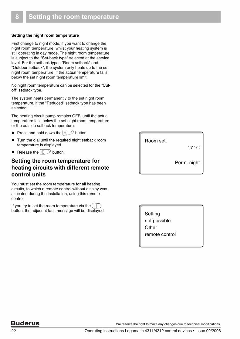
Setting the night room temperature
First change to night mode, if you want to change the night room temperature, whilst your heating system is still operating in day mode. The night room temperature is subject to the "Set-back type" selected at the service level. For the setback types "Room setback" and "Outdoor setback", the system only heats up to the set night room temperature, if the actual temperature falls below the set night room temperature limit.
No night room temperature can be selected for the "Cut-off" setback type.
The system heats permanently to the set night room temperature, if the "Reduced" setback type has been selected.
The heating circuit pump remains OFF, until the actual temperature falls below the set night room temperature or the outside setback temperature.
Press and hold down the F button.
Turn the dial until the required night setback room temperature is displayed.
Release the F button.
Setting the room temperature for heating circuits with different remote control units
You must set the room temperature for all heating circuits, to which a remote control without display was allocated during the installation, using this remote control.
If you try to set the room temperature via the G button, the adjacent fault message will be displayed.
Room set.17 °C
Perm. night
Settingnot possibleOtherremote control
22 Operating instructions Logamatic 4311/4312 control devices • Issue 02/2006
We reserve the right to make any changes due to technical modifications.
DHW (Domestic Hot Water) control 9
9 DHW (Domestic Hot Water) control
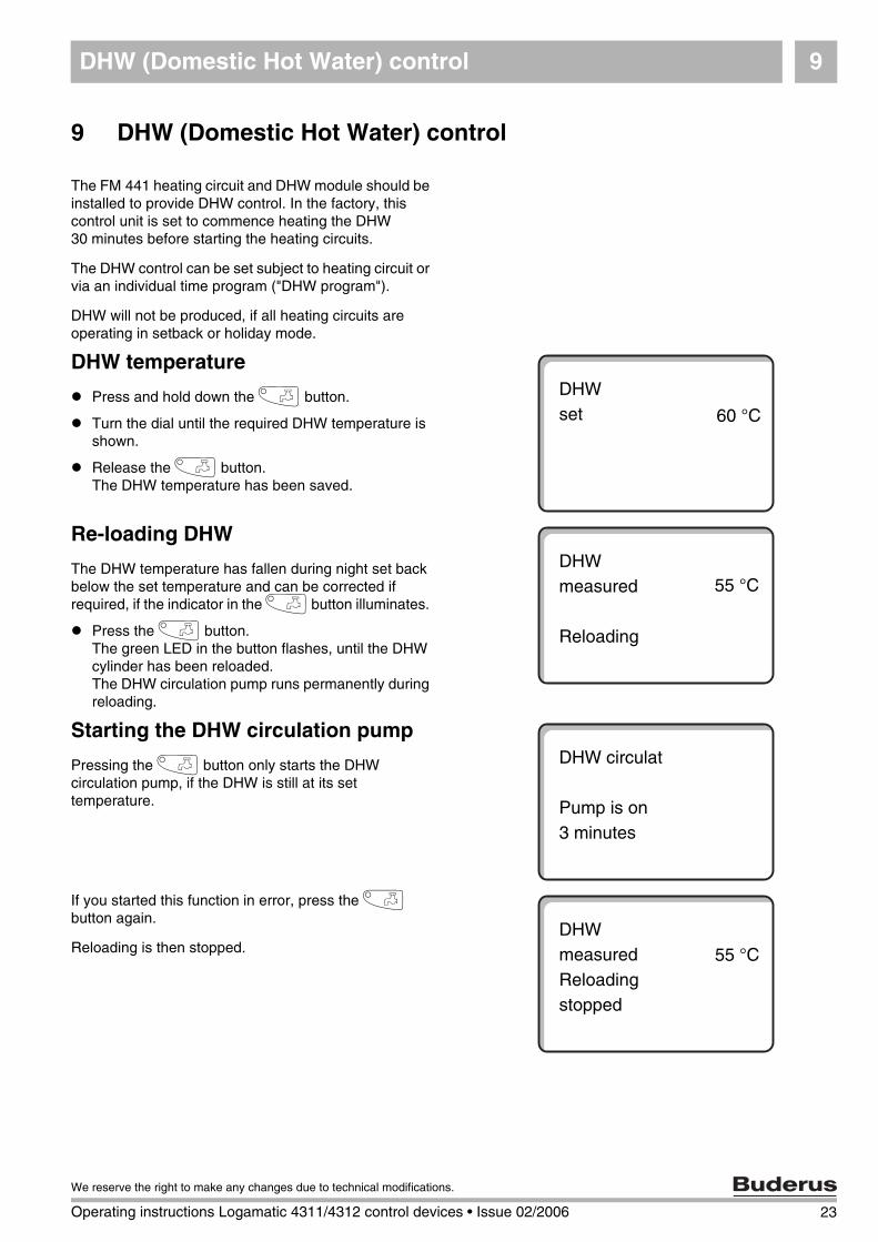
The FM 441 heating circuit and DHW module should be installed to provide DHW control. In the factory, this control unit is set to commence heating the DHW 30 minutes before starting the heating circuits.
The DHW control can be set subject to heating circuit or via an individual time program ("DHW program").
DHW will not be produced, if all heating circuits are operating in setback or holiday mode.
DHW temperature
Press and hold down the I button.
Turn the dial until the required DHW temperature is shown.
Release the I button.The DHW temperature has been saved.
Re-loading DHW
The DHW temperature has fallen during night set back below the set temperature and can be corrected if required, if the indicator in the I button illuminates.
Press the I button.The green LED in the button flashes, until the DHW cylinder has been reloaded. The DHW circulation pump runs permanently during reloading.
Starting the DHW circulation pump
Pressing the I button only starts the DHW circulation pump, if the DHW is still at its set temperature.
If you started this function in error, press the I button again.
Reloading is then stopped.
DHWset 60 °C
DHWmeasured
Reloading
55 °C
DHW circulat
Pump is on3 minutes
DHWmeasuredReloadingstopped
55 °C
23
We reserve the right to make any changes due to technical modifications.
Operating instructions Logamatic 4311/4312 control devices • Issue 02/2006
DHW (Domestic Hot Water) control9
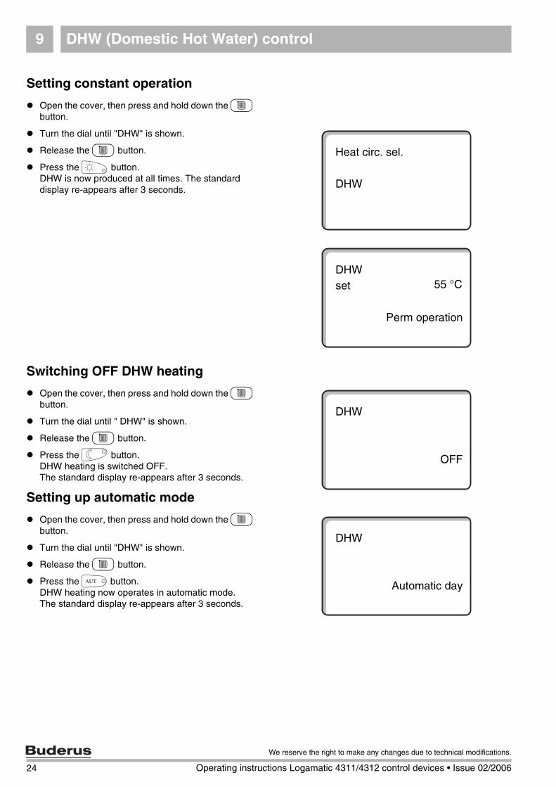
Setting constant operation
Open the cover, then press and hold down the C button.
Turn the dial until "DHW" is shown.
Release the C button.
Press the E button.DHW is now produced at all times. The standard display re-appears after 3 seconds.
Switching OFF DHW heating
Open the cover, then press and hold down the C button.
Turn the dial until " DHW" is shown.
Release the C button.
Press the F button.DHW heating is switched OFF.The standard display re-appears after 3 seconds.
Setting up automatic mode
Open the cover, then press and hold down the C button.
Turn the dial until "DHW" is shown.
Release the C button.
Press the D button.DHW heating now operates in automatic mode.The standard display re-appears after 3 seconds.
Heat circ. sel.
DHW
DHWset
Perm operation
55 °C
DHW
OFF
DHW
Automatic day
24 Operating instructions Logamatic 4311/4312 control devices • Issue 02/2006
We reserve the right to make any changes due to technical modifications.
DHW circulation pump control 10
10 DHW circulation pump control
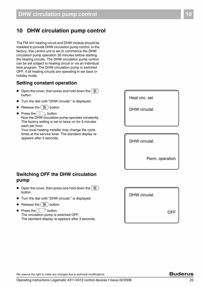
The FM 441 heating circuit and DHW module should be installed to provide DHW circulation pump control. In the factory, this control unit is set to commence the DHW circulation pump operation 30 minutes before starting the heating circuits. The DHW circulation pump control can be set subject to heating circuit or via an individual time program. The DHW circulation pump is switched OFF, if all heating circuits are operating in set back or holiday mode.
Setting constant operation
Open the cover, then press and hold down the C button.
Turn the dial until "DHW circulat." is displayed.
Release the C button.
Press the E button.Now the DHW circulation pump operates constantly. The factory setting is set to twice on for 3 minutes each per hour.Your local heating installer may change the cycle times at the service level. The standard display re-appears after 3 seconds.
Switching OFF the DHW circulation pump
Open the cover, then press and hold down the C button.
Turn the dial until "DHW circulat." is displayed.
Release the C button.
Press the F button.The circulation pump is switched OFF. The standard display re-appears after 3 seconds.
Heat circ. sel.
DHW circulat.
DHW circulat.
Perm. operation
DHW circulat.
OFF
25
We reserve the right to make any changes due to technical modifications.
Operating instructions Logamatic 4311/4312 control devices • Issue 02/2006
DHW circulation pump control10
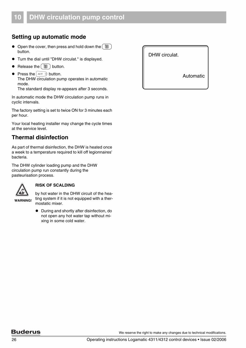
Setting up automatic mode
Open the cover, then press and hold down the C button.
Turn the dial until "DHW circulat." is displayed.
Release the C button.
Press the D button.The DHW circulation pump operates in automatic mode.The standard display re-appears after 3 seconds.
In automatic mode the DHW circulation pump runs in cyclic intervals.
The factory setting is set to twice ON for 3 minutes each per hour.
Your local heating installer may change the cycle times at the service level.
Thermal disinfection
As part of thermal disinfection, the DHW is heated once a week to a temperature required to kill off legionnaires' bacteria.
The DHW cylinder loading pump and the DHW circulation pump run constantly during the pasteurisation process.
DHW circulat.
Automatic
WARNING!
RISK OF SCALDING
by hot water in the DHW circuit of the hea-ting system if it is not equipped with a ther-mostatic mixer.
During and shortly after disinfection, do not open any hot water tap without mi-xing in some cold water.
26 Operating instructions Logamatic 4311/4312 control devices • Issue 02/2006
We reserve the right to make any changes due to technical modifications.
Calling up displays 11
27
We reserve the right to make any changes due to technical modifications.
Operating instructions Logamatic 4311/4312 control devices • Issue 02/2006
11 Calling up displays
Displaying operating settings
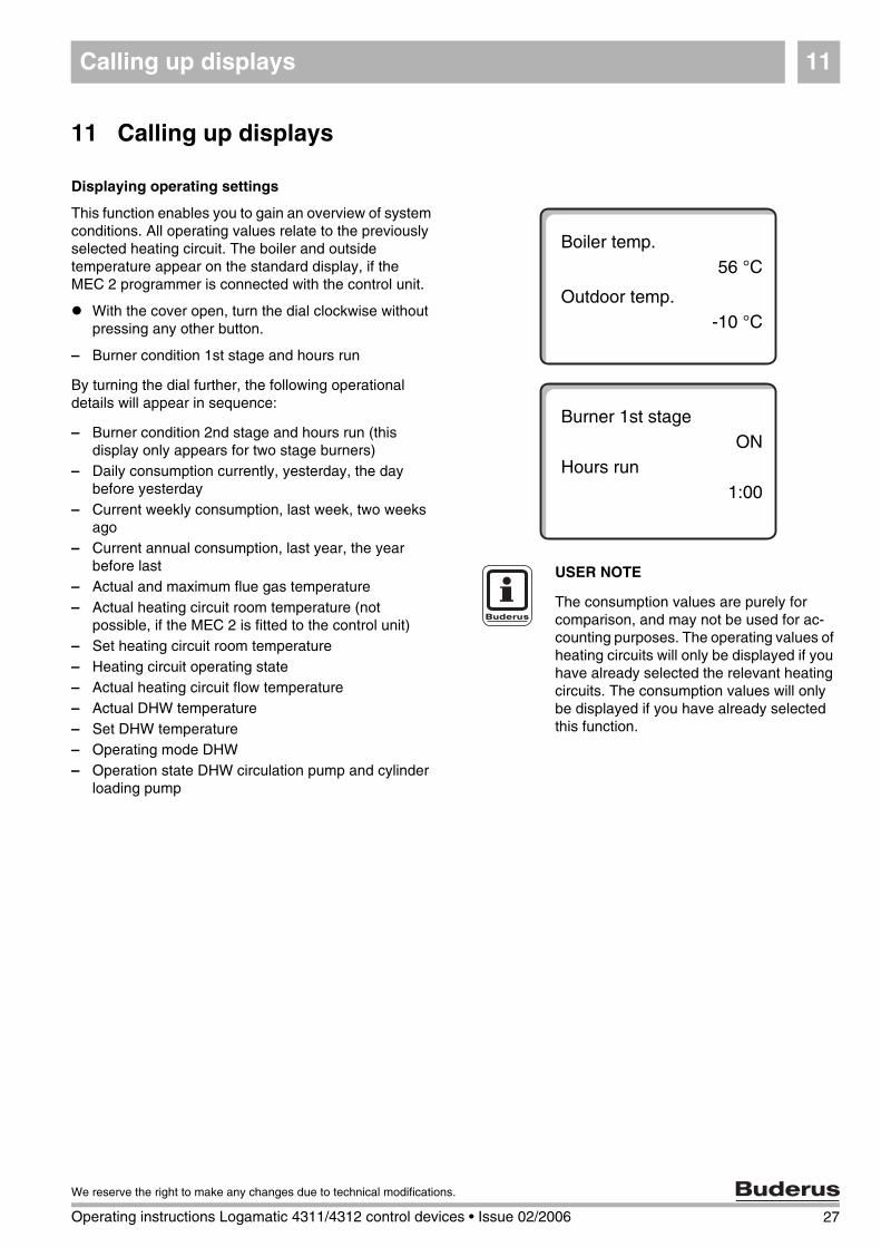
This function enables you to gain an overview of system conditions. All operating values relate to the previously selected heating circuit. The boiler and outside temperature appear on the standard display, if the MEC 2 programmer is connected with the control unit.
With the cover open, turn the dial clockwise without pressing any other button.
– Burner condition 1st stage and hours run
By turning the dial further, the following operational details will appear in sequence:
USER NOTE
The consumption values are purely for comparison, and may not be used for ac-counting purposes. The operating values of heating circuits will only be displayed if you have already selected the relevant heating circuits. The consumption values will only be displayed if you have already selected this function.
Burner 1st stageON
Hours run1:00
Boiler temp.56 °C
Outdoor temp.-10 °C
– Burner condition 2nd stage and hours run (this display only appears for two stage burners)
– Daily consumption currently, yesterday, the day before yesterday
– Current weekly consumption, last week, two weeks ago
– Current annual consumption, last year, the year before last
– Actual and maximum flue gas temperature– Actual heating circuit room temperature (not
possible, if the MEC 2 is fitted to the control unit)– Set heating circuit room temperature– Heating circuit operating state– Actual heating circuit flow temperature– Actual DHW temperature– Set DHW temperature– Operating mode DHW– Operation state DHW circulation pump and cylinder
loading pump
Selecting the standard program12
12 Selecting the standard program
A standard program is a switching program with typical switching times set up in the factory. You can select from eight standard programs (see overview of standard programs, page 31). The "Family" program is factory pre-set.
The standard programs can be used separately for each heating circuit. You can modify or supplement the switching points of a standard program to create your own individual program.
If you select "New", all previously entered switching points will be deleted, and you can arrange your own individual program. Your heating system will operate constantly in day mode, if neither a switching point nor a program is entered.
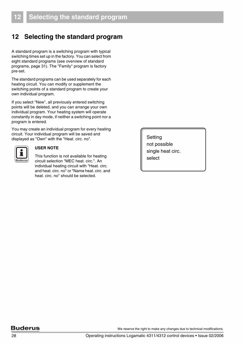
You may create an individual program for every heating circuit. Your individual program will be saved and displayed as "Own" with the "Heat. circ. no". Setting
not possiblesingle heat circ.select
USER NOTE
This function is not available for heating circuit selection "MEC heat. circ.". An individual heating circuit with "Heat. circ. and heat. circ. no" or "Name heat. circ. and heat. circ. no" should be selected.
28 Operating instructions Logamatic 4311/4312 control devices • Issue 02/2006
We reserve the right to make any changes due to technical modifications.
Selecting the standard program 12
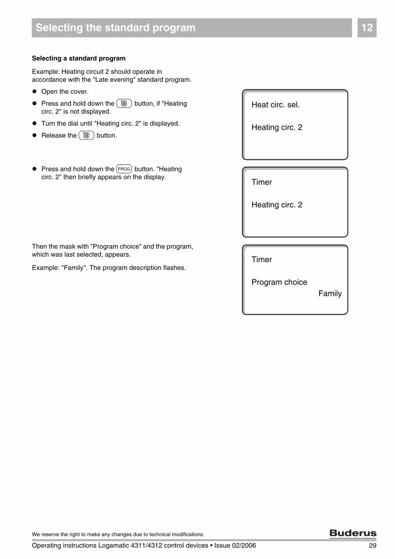
Selecting a standard program
Example: Heating circuit 2 should operate in accordance with the "Late evening" standard program.
Open the cover.
Press and hold down the C button, if "Heating circ. 2" is not displayed.
Turn the dial until "Heating circ. 2" is displayed.
Release the C button.
Press and hold down the J button. "Heating circ. 2" then briefly appears on the display.
Then the mask with "Program choice" and the program, which was last selected, appears.
Example: "Family". The program description flashes.
Heat circ. sel.
Heating circ. 2
Timer
Heating circ. 2
Timer
Program choiceFamily
29
We reserve the right to make any changes due to technical modifications.
Operating instructions Logamatic 4311/4312 control devices • Issue 02/2006
Selecting the standard program12
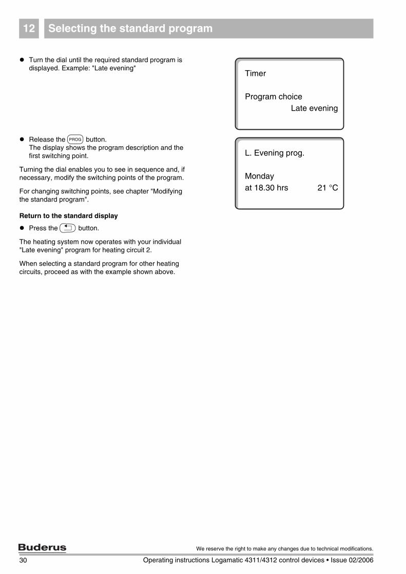
Turn the dial until the required standard program is displayed. Example: "Late evening"
Release the J button.The display shows the program description and the first switching point.
Turning the dial enables you to see in sequence and, if necessary, modify the switching points of the program.
For changing switching points, see chapter "Modifying the standard program".
Return to the standard display
Press the K button.
The heating system now operates with your individual "Late evening" program for heating circuit 2.
When selecting a standard program for other heating circuits, proceed as with the example shown above.
Timer
Program choiceLate evening
L. Evening prog.
Mondayat 18.30 hrs 21 °C
30 Operating instructions Logamatic 4311/4312 control devices • Issue 02/2006
We reserve the right to make any changes due to technical modifications.
Selecting the standard program 12
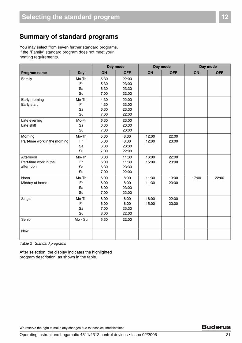
Summary of standard programs
You may select from seven further standard programs, if the "Family" standard program does not meet your heating requirements.
After selection, the display indicates the highlighted program description, as shown in the table.
Day mode Day mode Day mode
Program name Day ON OFF ON OFF ON OFF
Family Mo-ThFrSaSu
5:305:306:307:00
22:0023:0023:3022:00
Early morningEarly start
Mo-ThFrSaSu
4:304:306:307:00
22:0023:0023:3022:00
Late eveningLate shift
Mo-FrSaSu
6:306:307:00
23:0023:3023:00
MorningPart-time work in the morning
Mo-ThFrSaSu
5:305:306:307:00
8:308:3023:3022:00
12:0012:00
22:0023:00
AfternoonPart-time work in the afternoon
Mo-ThFrSaSu
6:006:006:307:00
11:3011:3023:3022:00
16:0015:00
22:0023:00
NoonMidday at home
Mo-ThFrSaSu
6:006:006:007:00
8:008:0023:0022:00
11:3011:30
13:0023:00
17:00 22:00
Single Mo-ThFrSaSu
6:006:007:008:00
8:008:0023:3022:00
16:0015:00
22:0023:00
Senior Mo - Su 5:30 22:00
New
Table 2 Standard programs
31
We reserve the right to make any changes due to technical modifications.
Operating instructions Logamatic 4311/4312 control devices • Issue 02/2006
Changing a program13
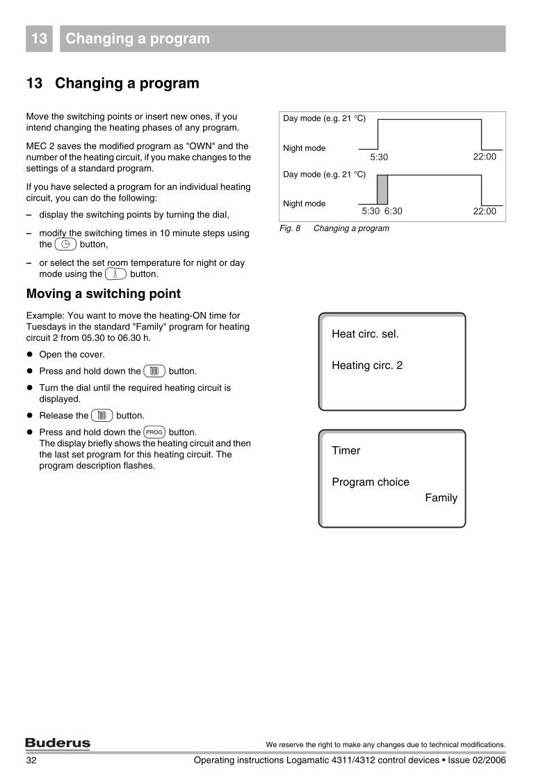
13 Changing a program
Move the switching points or insert new ones, if you intend changing the heating phases of any program.
MEC 2 saves the modified program as "OWN" and the number of the heating circuit, if you make changes to the settings of a standard program.
If you have selected a program for an individual heating circuit, you can do the following:
– display the switching points by turning the dial,
– modify the switching times in 10 minute steps using the L button,
– or select the set room temperature for night or day mode using the G button.
Moving a switching point
Example: You want to move the heating-ON time for Tuesdays in the standard "Family" program for heating circuit 2 from 05.30 to 06.30 h.
Open the cover.
Press and hold down the C button.
Turn the dial until the required heating circuit is displayed.
Release the C button.
Press and hold down the J button.The display briefly shows the heating circuit and then the last set program for this heating circuit. The program description flashes.
Fig. 8 Changing a program
Day mode (e.g. 21 °C)
Night mode
Day mode (e.g. 21 °C)
Night mode
Heat circ. sel.
Heating circ. 2
Timer
Program choiceFamily
32 Operating instructions Logamatic 4311/4312 control devices • Issue 02/2006
We reserve the right to make any changes due to technical modifications.
Changing a program 13
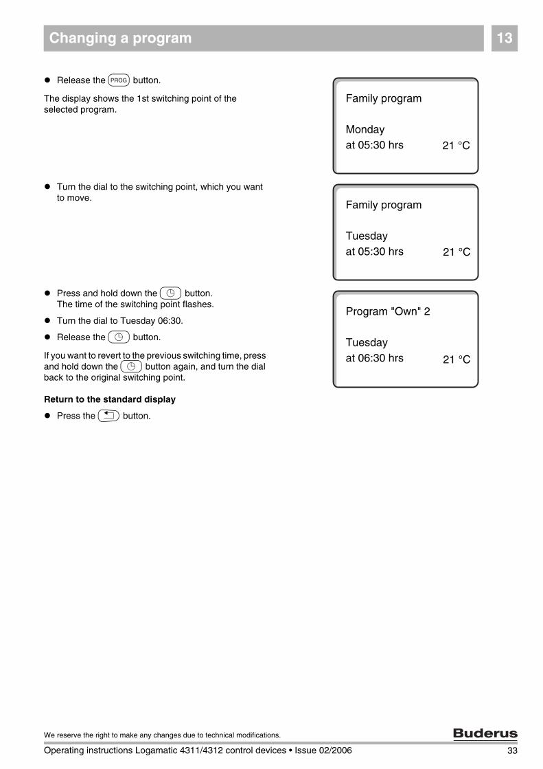
Release the J button.
The display shows the 1st switching point of the selected program.
Turn the dial to the switching point, which you want to move.
Press and hold down the L button.The time of the switching point flashes.
Turn the dial to Tuesday 06:30.
Release the L button.
If you want to revert to the previous switching time, press and hold down the L button again, and turn the dial back to the original switching point.
Return to the standard display
Press the K button.
Family program
Mondayat 05:30 hrs 21 °C
Family program
Tuesdayat 05:30 hrs 21 °C
Program "Own" 2
Tuesdayat 06:30 hrs 21 °C
33
We reserve the right to make any changes due to technical modifications.
Operating instructions Logamatic 4311/4312 control devices • Issue 02/2006
Changing a program13
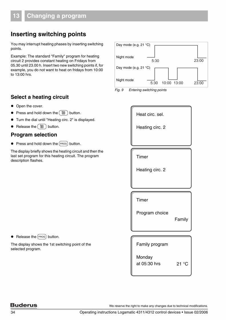
Inserting switching points
You may interrupt heating phases by inserting switching points.
Example: The standard "Family" program for heating circuit 2 provides constant heating on Fridays from 05.30 until 23.00 h. Insert two new switching points if, for example, you do not want to heat on fridays from 10:00 to 13:00 hrs.
Select a heating circuit
Open the cover.
Press and hold down the C button.
Turn the dial until "Heating circ. 2" is displayed.
Release the C button.
Program selection
Press and hold down the J button.
The display briefly shows the heating circuit and then the last set program for this heating circuit. The program description flashes.
Release the J button.
The display shows the 1st switching point of the selected program.
Fig. 9 Entering switching points
Day mode (e.g. 21 °C)
Night mode
Day mode (e.g. 21 °C)
Night mode
Heat circ. sel.
Heating circ. 2
Timer
Heating circ. 2
Timer
Program choiceFamily
Family program
Mondayat 05:30 hrs 21 °C
34 Operating instructions Logamatic 4311/4312 control devices • Issue 02/2006
We reserve the right to make any changes due to technical modifications.
Changing a program 13
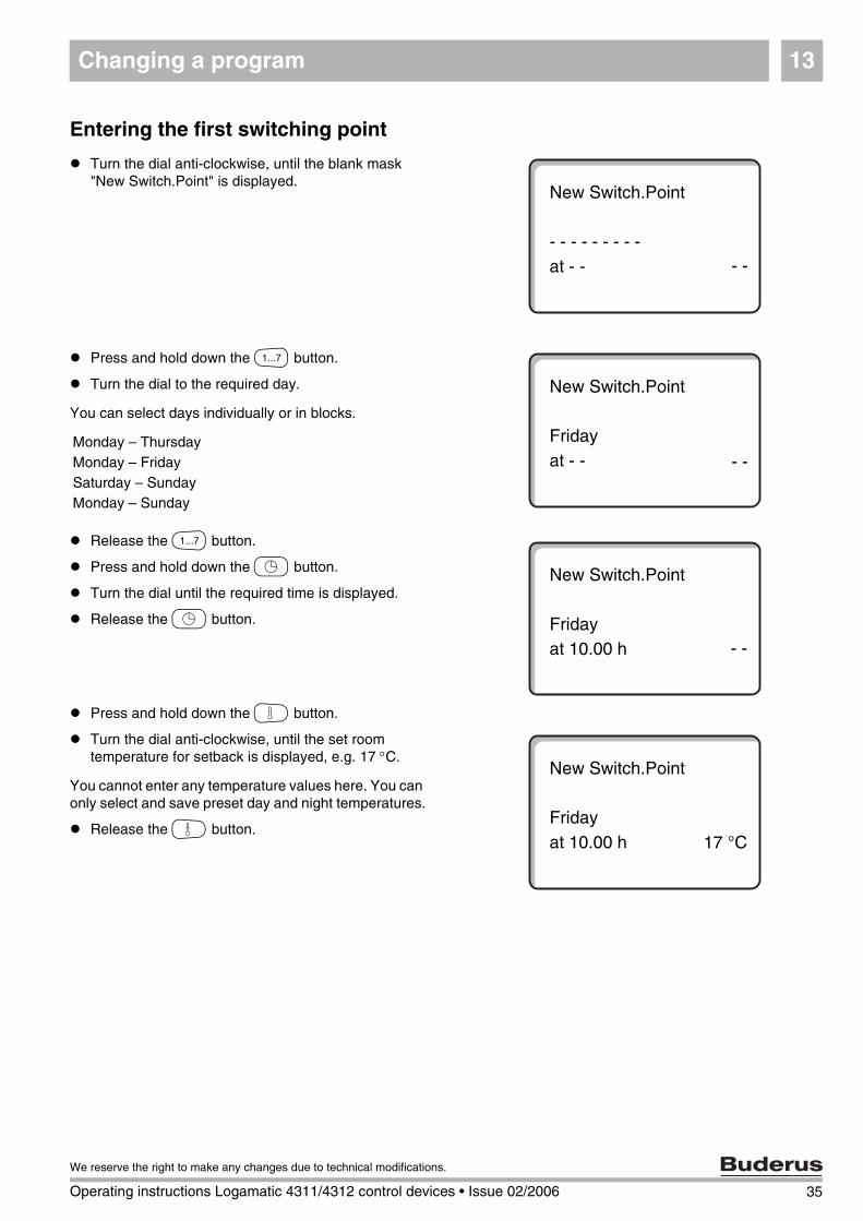
Entering the first switching point
Turn the dial anti-clockwise, until the blank mask "New Switch.Point" is displayed.
Press and hold down the M button.
Turn the dial to the required day.
You can select days individually or in blocks.
Release the M button.
Press and hold down the L button.
Turn the dial until the required time is displayed.
Release the L button.
Press and hold down the G button.
Turn the dial anti-clockwise, until the set room temperature for setback is displayed, e.g. 17 °C.
You cannot enter any temperature values here. You can only select and save preset day and night temperatures.
Release the G button.
New Switch.Point
- - - - - - - - - at - - - -
New Switch.Point
Fridayat - - - -
New Switch.Point
Fridayat 10.00 h - -
Monday – ThursdayMonday – FridaySaturday – SundayMonday – Sunday
New Switch.Point
Fridayat 10.00 h 17 °C
35
We reserve the right to make any changes due to technical modifications.
Operating instructions Logamatic 4311/4312 control devices • Issue 02/2006
Changing a program13
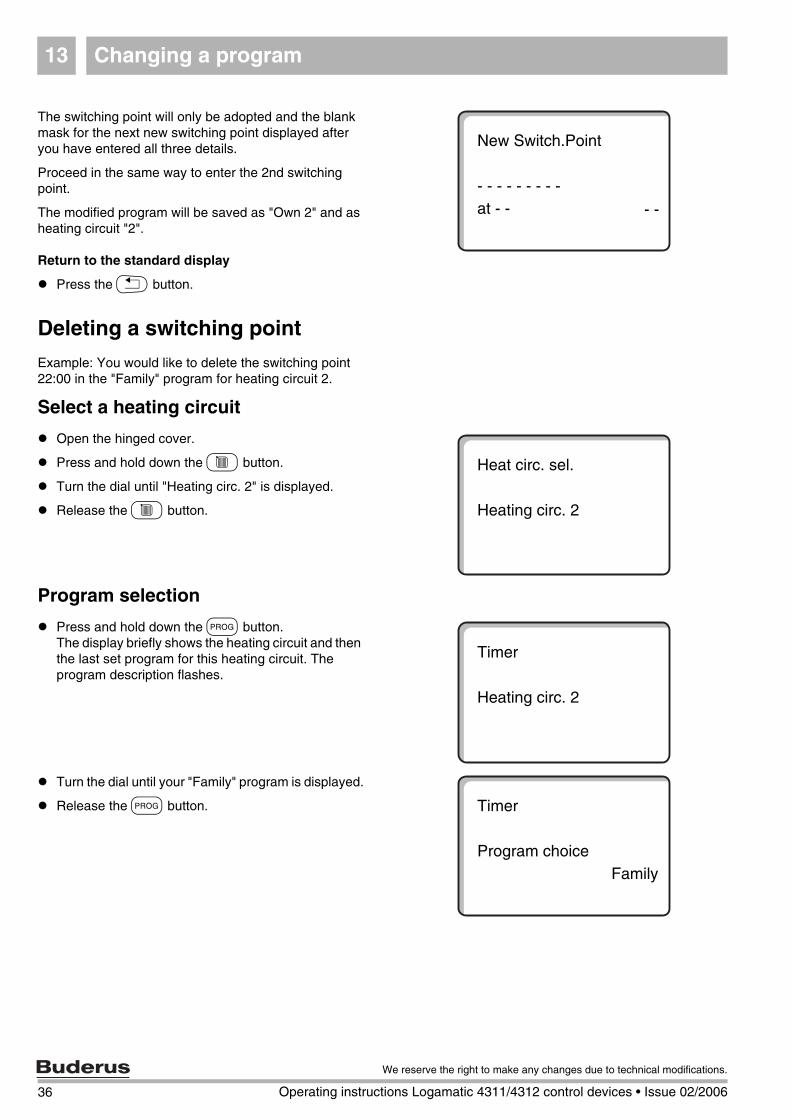
The switching point will only be adopted and the blank mask for the next new switching point displayed after you have entered all three details.
Proceed in the same way to enter the 2nd switching point.
The modified program will be saved as "Own 2" and as heating circuit "2".
Return to the standard display
Press the K button.
Deleting a switching point
Example: You would like to delete the switching point 22:00 in the "Family" program for heating circuit 2.
Select a heating circuit
Open the hinged cover.
Press and hold down the C button.
Turn the dial until "Heating circ. 2" is displayed.
Release the C button.
Program selection
Press and hold down the J button. The display briefly shows the heating circuit and then the last set program for this heating circuit. The program description flashes.
Turn the dial until your "Family" program is displayed.
Release the J button.
New Switch.Point
- - - - - - - - - at - - - -
Heat circ. sel.
Heating circ. 2
Timer
Heating circ. 2
Timer
Program choiceFamily
36 Operating instructions Logamatic 4311/4312 control devices • Issue 02/2006
We reserve the right to make any changes due to technical modifications.
Changing a program 13
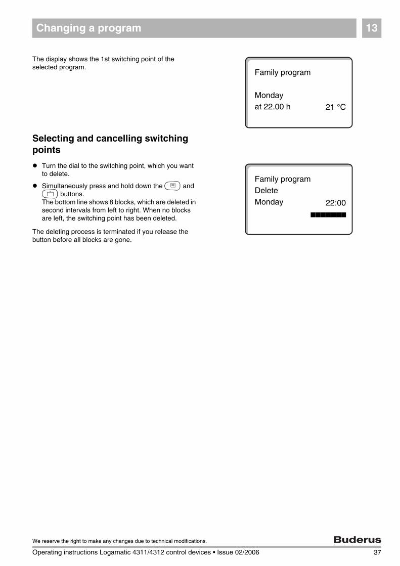
The display shows the 1st switching point of the selected program.
Selecting and cancelling switching points
Turn the dial to the switching point, which you want to delete.
Simultaneously press and hold down the N and O buttons.The bottom line shows 8 blocks, which are deleted in second intervals from left to right. When no blocks are left, the switching point has been deleted.
The deleting process is terminated if you release the button before all blocks are gone.
Family program
Mondayat 22.00 h 21 °C
Family programDeleteMonday
hhhhhhh
22:00
37
We reserve the right to make any changes due to technical modifications.
Operating instructions Logamatic 4311/4312 control devices • Issue 02/2006
Changing a program13
Deleting a heating phase
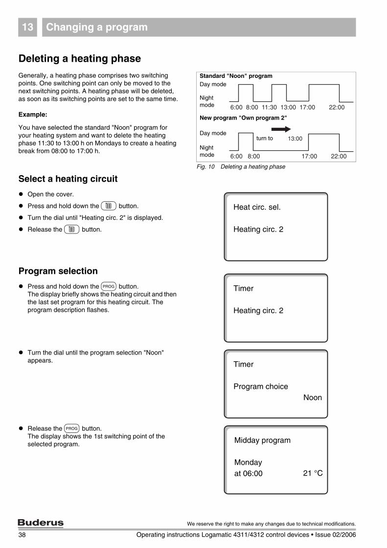
Generally, a heating phase comprises two switching points. One switching point can only be moved to the next switching points. A heating phase will be deleted, as soon as its switching points are set to the same time.
Example:
You have selected the standard "Noon" program for your heating system and want to delete the heating phase 11:30 to 13:00 h on Mondays to create a heating break from 08:00 to 17:00 h.
Select a heating circuit
Open the cover.
Press and hold down the C button.
Turn the dial until "Heating circ. 2" is displayed.
Release the C button.
Program selection
Press and hold down the J button.The display briefly shows the heating circuit and then the last set program for this heating circuit. The program description flashes.
Turn the dial until the program selection "Noon" appears.
Release the J button.The display shows the 1st switching point of the selected program.
Fig. 10 Deleting a heating phase
Day mode
Nightmode
Day mode
Nightmode
New program "Own program 2"
Standard "Noon" program
turn to
Heat circ. sel.
Heating circ. 2
Timer
Heating circ. 2
Timer
Program choiceNoon
Midday program
Mondayat 06:00 21 °C
38 Operating instructions Logamatic 4311/4312 control devices • Issue 02/2006
We reserve the right to make any changes due to technical modifications.
Changing a program 13
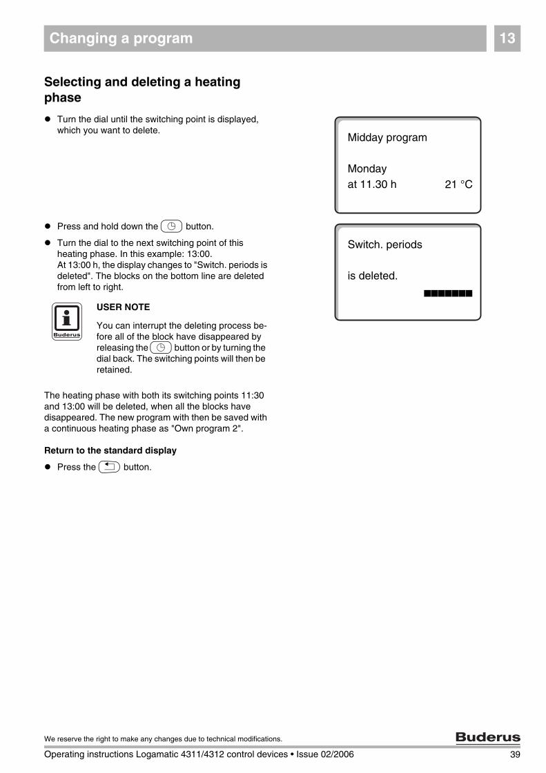
Selecting and deleting a heating phase
Turn the dial until the switching point is displayed, which you want to delete.
Press and hold down the L button.
Turn the dial to the next switching point of this heating phase. In this example: 13:00.At 13:00 h, the display changes to "Switch. periods is deleted". The blocks on the bottom line are deleted from left to right.
The heating phase with both its switching points 11:30 and 13:00 will be deleted, when all the blocks have disappeared. The new program with then be saved with a continuous heating phase as "Own program 2".
Return to the standard display
Press the K button.
Midday program
Mondayat 11.30 h 21 °C
Switch. periods
is deleted.hhhhhhh
USER NOTE
You can interrupt the deleting process be-fore all of the block have disappeared by releasing the L button or by turning the dial back. The switching points will then be retained.
39
We reserve the right to make any changes due to technical modifications.
Operating instructions Logamatic 4311/4312 control devices • Issue 02/2006
Changing a program13
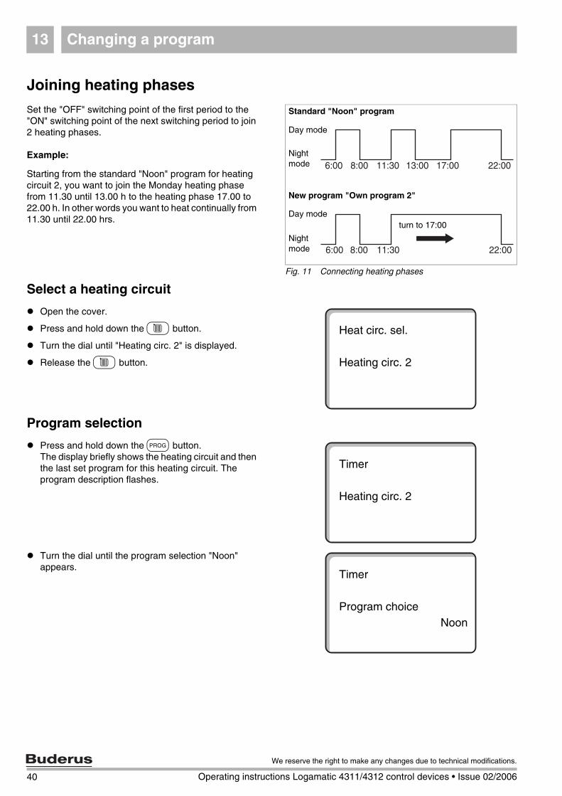
Joining heating phases
Set the "OFF" switching point of the first period to the "ON" switching point of the next switching period to join 2 heating phases.
Example:
Starting from the standard "Noon" program for heating circuit 2, you want to join the Monday heating phase from 11.30 until 13.00 h to the heating phase 17.00 to 22.00 h. In other words you want to heat continually from 11.30 until 22.00 hrs.
Select a heating circuit
Open the cover.
Press and hold down the C button.
Turn the dial until "Heating circ. 2" is displayed.
Release the C button.
Program selection
Press and hold down the J button.The display briefly shows the heating circuit and then the last set program for this heating circuit. The program description flashes.
Turn the dial until the program selection "Noon" appears.
Fig. 11 Connecting heating phases
Day mode
Nightmode
Day mode
Nightmode
New program "Own program 2"
Standard "Noon" program
turn to 17:00
Heat circ. sel.
Heating circ. 2
Timer
Heating circ. 2
Timer
Program choiceNoon
40 Operating instructions Logamatic 4311/4312 control devices • Issue 02/2006
We reserve the right to make any changes due to technical modifications.
Changing a program 13
Release the J button.
The display shows the 1st switching point of the selected program.
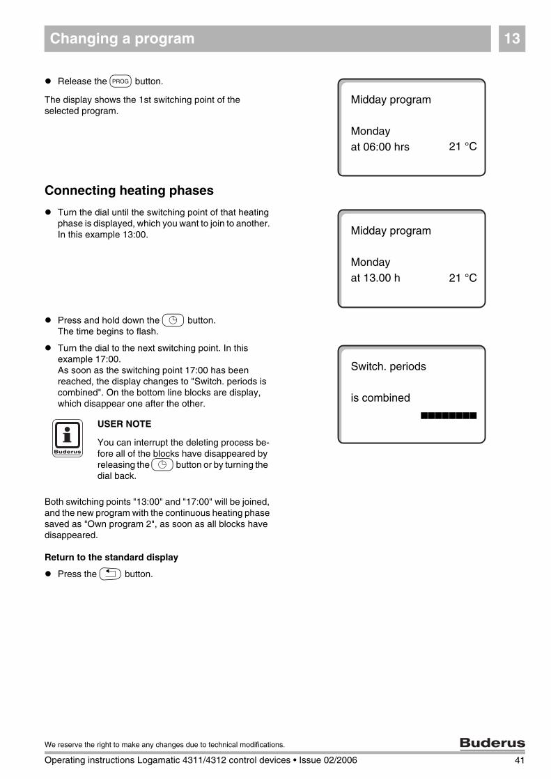
Connecting heating phases
Turn the dial until the switching point of that heating phase is displayed, which you want to join to another. In this example 13:00.
Press and hold down the L button.The time begins to flash.
Turn the dial to the next switching point. In this example 17:00.As soon as the switching point 17:00 has been reached, the display changes to "Switch. periods is combined". On the bottom line blocks are display, which disappear one after the other.
Both switching points "13:00" and "17:00" will be joined, and the new program with the continuous heating phase saved as "Own program 2", as soon as all blocks have disappeared.
Return to the standard display
Press the K button.
Midday program
Mondayat 06:00 hrs 21 °C
Midday program
Mondayat 13.00 h 21 °C
Switch. periods
is combinedhhhhhhhh
USER NOTE
You can interrupt the deleting process be-fore all of the blocks have disappeared by releasing the L button or by turning the dial back.
41
We reserve the right to make any changes due to technical modifications.
Operating instructions Logamatic 4311/4312 control devices • Issue 02/2006
Creating a new heating program14
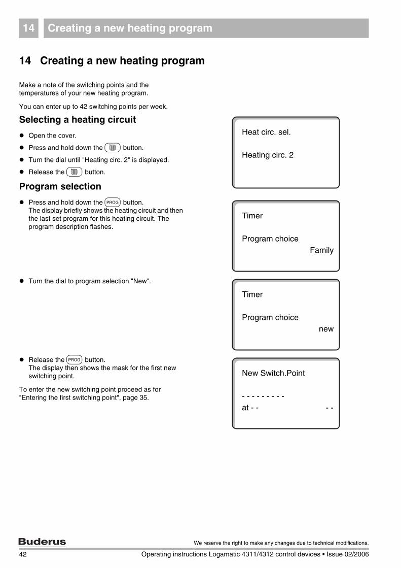
14 Creating a new heating program
Make a note of the switching points and the temperatures of your new heating program.
You can enter up to 42 switching points per week.
Selecting a heating circuit
Open the cover.
Press and hold down the C button.
Turn the dial until "Heating circ. 2" is displayed.
Release the C button.
Program selection
Press and hold down the J button.The display briefly shows the heating circuit and then the last set program for this heating circuit. The program description flashes.
Turn the dial to program selection "New".
Release the J button.The display then shows the mask for the first new switching point.
To enter the new switching point proceed as for "Entering the first switching point", page 35.
Heat circ. sel.
Heating circ. 2
Timer
Program choiceFamily
Timer
Program choicenew
New Switch.Point
- - - - - - - - - at - - - -
42 Operating instructions Logamatic 4311/4312 control devices • Issue 02/2006
We reserve the right to make any changes due to technical modifications.
Creating a new heating program 14
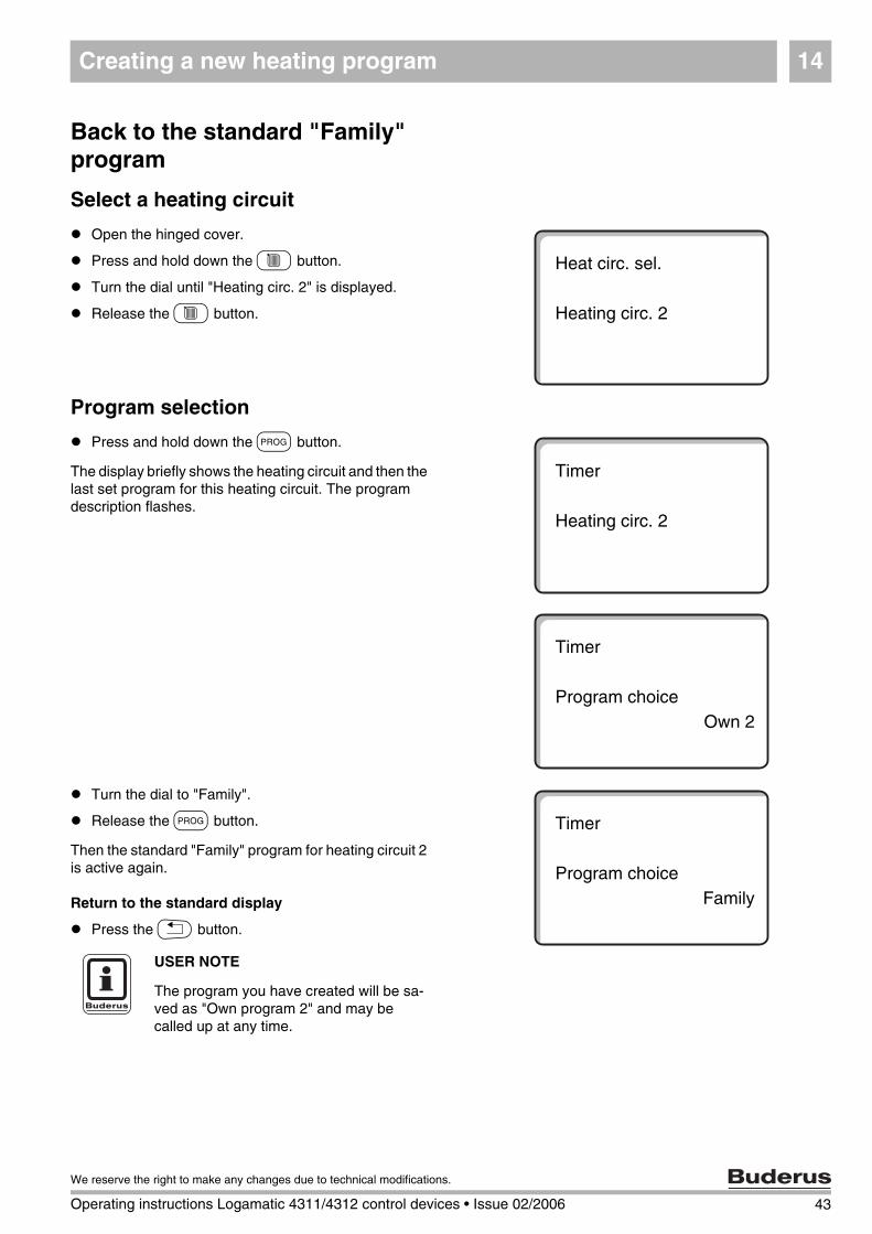
Back to the standard "Family" program
Select a heating circuit
Open the hinged cover.
Press and hold down the C button.
Turn the dial until "Heating circ. 2" is displayed.
Release the C button.
Program selection
Press and hold down the J button.
The display briefly shows the heating circuit and then the last set program for this heating circuit. The program description flashes.
Turn the dial to "Family".
Release the J button.
Then the standard "Family" program for heating circuit 2 is active again.
Return to the standard display
Press the K button.
Heat circ. sel.
Heating circ. 2
Timer
Heating circ. 2
Timer
Program choiceOwn 2
Timer
Program choiceFamily
USER NOTE
The program you have created will be sa-ved as "Own program 2" and may be called up at any time.
43
We reserve the right to make any changes due to technical modifications.
Operating instructions Logamatic 4311/4312 control devices • Issue 02/2006
44 Operating instructions Logamatic 4311/4312 control devices • Issue 02/2006
We reserve the right to make any changes due to technical modifications.
Entering a new DHW program15
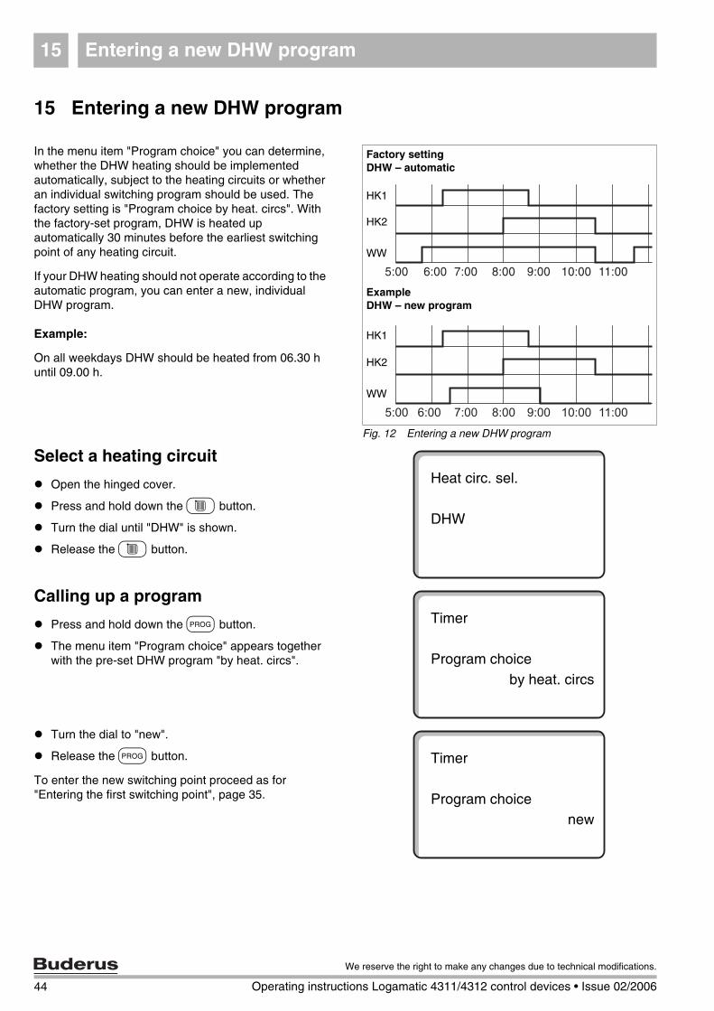
15 Entering a new DHW program
In the menu item "Program choice" you can determine, whether the DHW heating should be implemented automatically, subject to the heating circuits or whether an individual switching program should be used. The factory setting is "Program choice by heat. circs". With the factory-set program, DHW is heated up automatically 30 minutes before the earliest switching point of any heating circuit.
If your DHW heating should not operate according to the automatic program, you can enter a new, individual DHW program.
Example:
On all weekdays DHW should be heated from 06.30 h until 09.00 h.
Select a heating circuit
Open the hinged cover.
Press and hold down the C button.
Turn the dial until "DHW" is shown.
Release the C button.
Calling up a program
Press and hold down the J button.
The menu item "Program choice" appears together with the pre-set DHW program "by heat. circs".
Turn the dial to "new".
Release the J button.
To enter the new switching point proceed as for "Entering the first switching point", page 35.
Fig. 12 Entering a new DHW program
Factory settingDHW – automatic
HK1
HK2
WW
Example DHW – new program
HK1
HK2
WW
Heat circ. sel.
DHW
Timer
Program choiceby heat. circs
Timer
Program choicenew
Entering a new DHW secondary circulation pump program 16
45
We reserve the right to make any changes due to technical modifications.
Operating instructions Logamatic 4311/4312 control devices • Issue 02/2006
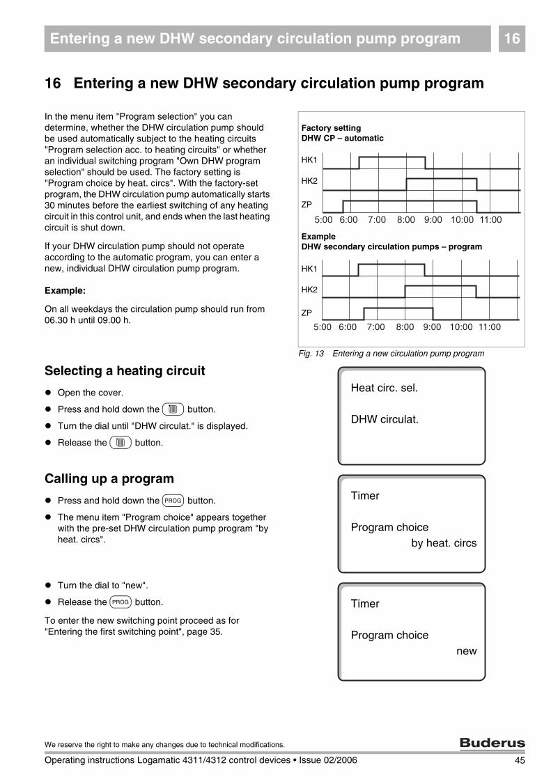
16 Entering a new DHW secondary circulation pump program
In the menu item "Program selection" you can determine, whether the DHW circulation pump should be used automatically subject to the heating circuits "Program selection acc. to heating circuits" or whether an individual switching program "Own DHW program selection" should be used. The factory setting is "Program choice by heat. circs". With the factory-set program, the DHW circulation pump automatically starts 30 minutes before the earliest switching of any heating circuit in this control unit, and ends when the last heating circuit is shut down.
If your DHW circulation pump should not operate according to the automatic program, you can enter a new, individual DHW circulation pump program.
Example:
On all weekdays the circulation pump should run from 06.30 h until 09.00 h.
Selecting a heating circuit
Open the cover.
Press and hold down the C button.
Turn the dial until "DHW circulat." is displayed.
Release the C button.
Calling up a program
Press and hold down the J button.
The menu item "Program choice" appears together with the pre-set DHW circulation pump program "by heat. circs".
Turn the dial to "new".
Release the J button.
To enter the new switching point proceed as for "Entering the first switching point", page 35.
Fig. 13 Entering a new circulation pump program
Factory settingDHW CP – automatic
HK1
HK2
ZP
ExampleDHW secondary circulation pumps – program
HK1
HK2
ZP
Heat circ. sel.
DHW circulat.
Timer
Program choiceby heat. circs
Timer
Program choicenew
Party/Pause function17
17 Party/Pause function
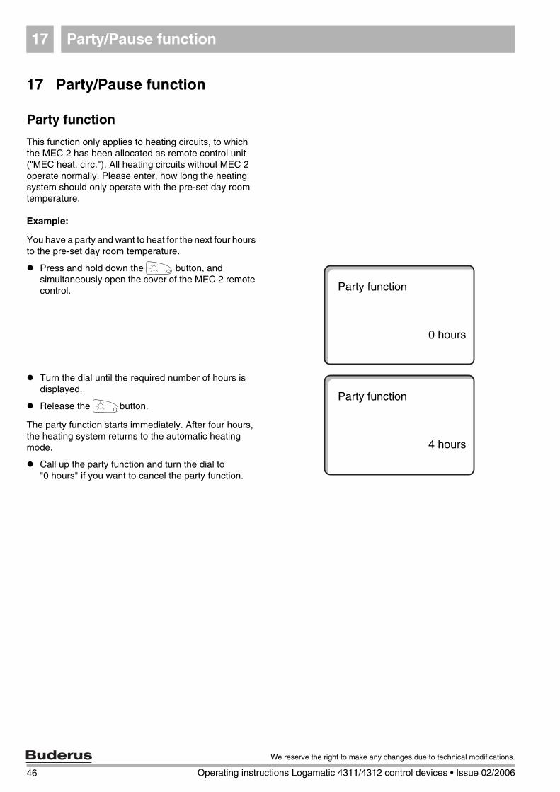
Party function
This function only applies to heating circuits, to which the MEC 2 has been allocated as remote control unit ("MEC heat. circ."). All heating circuits without MEC 2 operate normally. Please enter, how long the heating system should only operate with the pre-set day room temperature.
Example:
You have a party and want to heat for the next four hours to the pre-set day room temperature.
Press and hold down the E button, and simultaneously open the cover of the MEC 2 remote control.
Turn the dial until the required number of hours is displayed.
Release the Ebutton.
The party function starts immediately. After four hours, the heating system returns to the automatic heating mode.
Call up the party function and turn the dial to "0 hours" if you want to cancel the party function.
Party function
0 hours
Party function
4 hours
46 Operating instructions Logamatic 4311/4312 control devices • Issue 02/2006
We reserve the right to make any changes due to technical modifications.
Party/Pause function 17
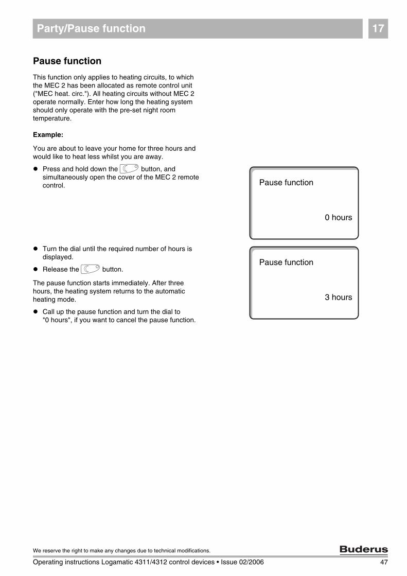
Pause function
This function only applies to heating circuits, to which the MEC 2 has been allocated as remote control unit ("MEC heat. circ."). All heating circuits without MEC 2 operate normally. Enter how long the heating system should only operate with the pre-set night room temperature.
Example:
You are about to leave your home for three hours and would like to heat less whilst you are away.
Press and hold down the F button, and simultaneously open the cover of the MEC 2 remote control.
Turn the dial until the required number of hours is displayed.
Release the F button.
The pause function starts immediately. After three hours, the heating system returns to the automatic heating mode.
Call up the pause function and turn the dial to "0 hours", if you want to cancel the pause function.
Pause function
0 hours
Pause function
3 hours
47
We reserve the right to make any changes due to technical modifications.
Operating instructions Logamatic 4311/4312 control devices • Issue 02/2006
Holiday program18
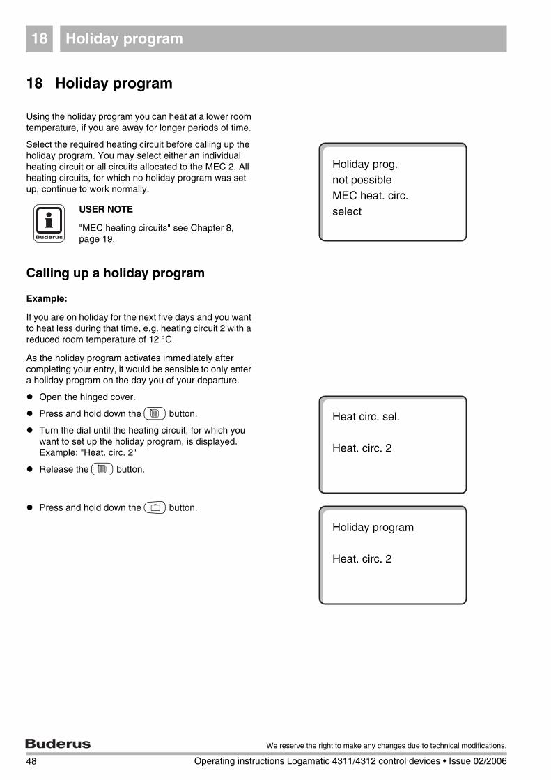
18 Holiday program
Using the holiday program you can heat at a lower room temperature, if you are away for longer periods of time.
Select the required heating circuit before calling up the holiday program. You may select either an individual heating circuit or all circuits allocated to the MEC 2. All heating circuits, for which no holiday program was set up, continue to work normally.
Calling up a holiday program
Example:
If you are on holiday for the next five days and you want to heat less during that time, e.g. heating circuit 2 with a reduced room temperature of 12 °C.
As the holiday program activates immediately after completing your entry, it would be sensible to only enter a holiday program on the day you of your departure.
Open the hinged cover.
Press and hold down the C button.
Turn the dial until the heating circuit, for which you want to set up the holiday program, is displayed. Example: "Heat. circ. 2"
Release the C button.
Press and hold down the O button.
Holiday prog.not possibleMEC heat. circ.selectUSER NOTE
"MEC heating circuits" see Chapter 8, page 19.
Heat circ. sel.
Heat. circ. 2
Holiday program
Heat. circ. 2
48 Operating instructions Logamatic 4311/4312 control devices • Issue 02/2006
We reserve the right to make any changes due to technical modifications.
Holiday program 18
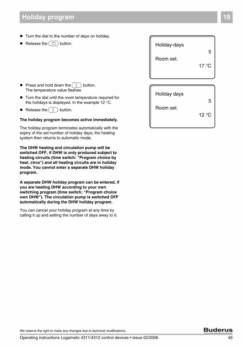
Turn the dial to the number of days on holiday.
Release the O button.
Press and hold down the G button.The temperature value flashes.
Turn the dial until the room temperature required for the holidays is displayed. In the example 12 °C.
Release the G button.
The holiday program becomes active immediately.
The holiday program terminates automatically with the expiry of the set number of holiday days; the heating system then returns to automatic mode.
The DHW heating and circulation pump will be switched OFF, if DHW is only produced subject to heating circuits (time switch: "Program choice by heat. circs") and all heating circuits are in holiday mode. You cannot enter a separate DHW holiday program.
A separate DHW holiday program can be entered, if you are heating DHW according to your own switching program (time switch: "Program choice own DHW"). The circulation pump is switched OFF automatically during the DHW holiday program.
You can cancel your holiday program at any time by calling it up and setting the number of days away to 0.
Holiday-days5
Room set.17 °C
Holiday days 5
Room set.12 °C
49
We reserve the right to make any changes due to technical modifications.
Operating instructions Logamatic 4311/4312 control devices • Issue 02/2006
Holiday program18
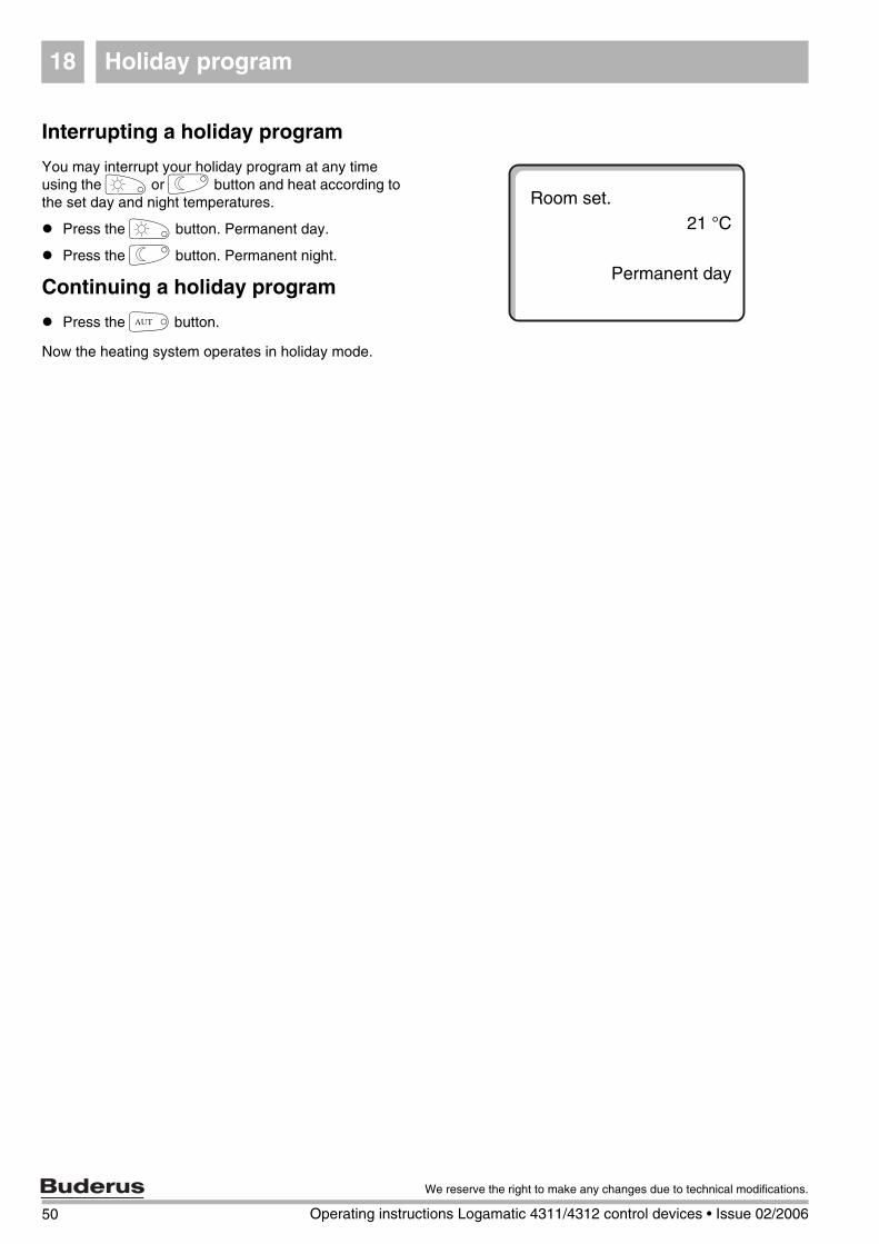
Interrupting a holiday program
You may interrupt your holiday program at any time using the E or F button and heat according to the set day and night temperatures.
Press the E button. Permanent day.
Press the F button. Permanent night.
Continuing a holiday program
Press the D button.
Now the heating system operates in holiday mode.
Room set.21 °C
Permanent day
50 Operating instructions Logamatic 4311/4312 control devices • Issue 02/2006
We reserve the right to make any changes due to technical modifications.
Setting summer/winter changeover 19
19 Setting summer/winter changeover
Apart from the outside temperature, Logamatic 4311 and Logamatic 4312 control units consider the ability to store heat and the thermal insulation of the building in question (in the following the "Time del. outdoor temp.") and automatically change over, with time delay, between summer and winter mode.
Summer mode
The heating operation will be switched OFF with a delay, which depends on the heat retaining capability and the thermal insulation of the building. If the "Time del. outdoor temp." exceeds the factory-set changeover threshold of 17 °C. Summer mode is indicated in the display with the symbol Y. DHW heating remains active.Press the E button, if you wish to heat for a short time in summer mode.
The heating system returns to automatic summer mode if you press the D button.
Winter mode
Central heating and DHW heating are active, if the "Time del. outdoor temp." falls below the factory-set changeover threshold of 17 °C.
51
We reserve the right to make any changes due to technical modifications.
Operating instructions Logamatic 4311/4312 control devices • Issue 02/2006
Setting summer/winter changeover19
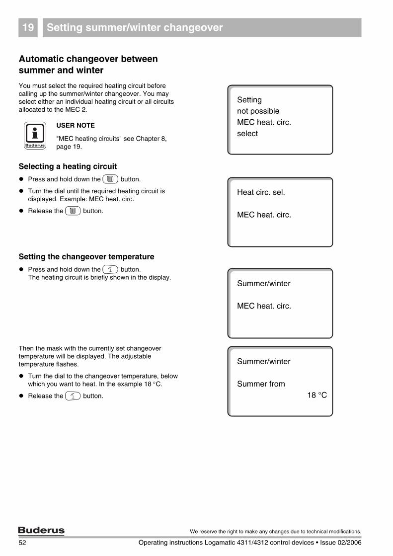
Automatic changeover between summer and winter
You must select the required heating circuit before calling up the summer/winter changeover. You may select either an individual heating circuit or all circuits allocated to the MEC 2.
Selecting a heating circuit
Press and hold down the C button.
Turn the dial until the required heating circuit is displayed. Example: MEC heat. circ.
Release the C button.
Setting the changeover temperature
Press and hold down the H button.The heating circuit is briefly shown in the display.
Then the mask with the currently set changeover temperature will be displayed. The adjustable temperature flashes.
Turn the dial to the changeover temperature, below which you want to heat. In the example 18 °C.
Release the H button.
Settingnot possibleMEC heat. circ.select
USER NOTE
"MEC heating circuits" see Chapter 8, page 19.
Heat circ. sel.
MEC heat. circ.
Summer/winter
MEC heat. circ.
Summer/winter
Summer from18 °C
52 Operating instructions Logamatic 4311/4312 control devices • Issue 02/2006
We reserve the right to make any changes due to technical modifications.
Setting summer/winter changeover 19
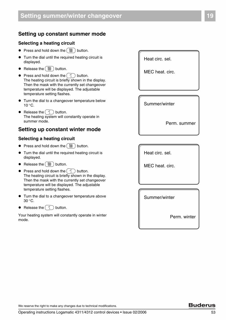
Setting up constant summer mode
Selecting a heating circuit
Press and hold down the C button.
Turn the dial until the required heating circuit is displayed.
Release the C button.
Press and hold down the H button.The heating circuit is briefly shown in the display. Then the mask with the currently set changeover temperature will be displayed. The adjustable temperature setting flashes.
Turn the dial to a changeover temperature below 10 °C.
Release the H button.The heating system will constantly operate in summer mode.
Setting up constant winter mode
Selecting a heating circuit
Press and hold down the C button.
Turn the dial until the required heating circuit is displayed.
Release the C button.
Press and hold down the H button.The heating circuit is briefly shown in the display. Then the mask with the currently set changeover temperature will be displayed. The adjustable temperature setting flashes.
Turn the dial to a changeover temperature above 30 °C.
Release the H button.
Your heating system will constantly operate in winter mode.
Heat circ. sel.
MEC heat. circ.
Summer/winter
Perm. summer
Heat circ. sel.
MEC heat. circ.
Summer/winter
Perm. winter
53
We reserve the right to make any changes due to technical modifications.
Operating instructions Logamatic 4311/4312 control devices • Issue 02/2006
54 Operating instructions Logamatic 4311/4312 control devices • Issue 02/2006
We reserve the right to make any changes due to technical modifications.
Changing the standard display20
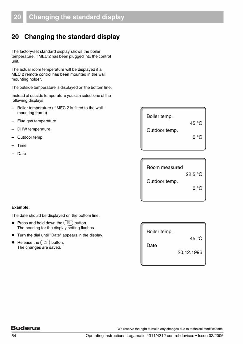
20 Changing the standard display
The factory-set standard display shows the boiler temperature, if MEC 2 has been plugged into the control unit.
The actual room temperature will be displayed if a MEC 2 remote control has been mounted in the wall mounting holder.
The outside temperature is displayed on the bottom line.
Instead of outside temperature you can select one of the following displays:
– Boiler temperature (if MEC 2 is fitted to the wall-mounting frame)
– Flue gas temperature
– DHW temperature
– Outdoor temp.
– Time
– Date
Example:
The date should be displayed on the bottom line.
Press and hold down the N button.The heading for the display setting flashes.
Turn the dial until "Date" appears in the display.
Release the N button.The changes are saved.
Boiler temp.45 °C
Outdoor temp.0 °C
Room measured 22.5 °C
Outdoor temp.0 °C
Boiler temp.45 °C
Date20.12.1996
Entering date and time 21
21 Entering date and time
(not currently available in the UK and should be switched off)
The date is set at the factory.
Date and time are synchronised daily via a radio signal [where available]. This also automatically changes between summer and winter. Well screened boiler rooms may impede the reception of the radio clock signal, which makes it necessary for you to set the date and time manually.
The MEC 2 contains a radio receiver (not currently available in the UK and should be switched off), which constantly monitors and corrects the time switch inside the control unit. This means, that you need never set the time during commissioning; after prolonged power failure, after the heating system has been switched OFF for longer periods on its mains electrical isolator or for changing from summer to winter and vice versa. Please note: this facility is subject to the availability of the radio clock signal.
For the MEC 2 remote control, the reception of the radio clock signal is subject to place and location.
Reception of the radio clock signal is indicated by the symbol P on the display.
In case of reception problems, please observe the following:
– The radio reception is weaker in rooms surrounded by steel-reinforced walls, in cellars, high-rise buildings, etc.
– The distance from sources of interference, such as computer monitors and TV sets, should be at least1-1.50 m.
– Atmospheric interference is not as strong at night than during the day, which is why reception is almost always possible [where generally available].
55
We reserve the right to make any changes due to technical modifications.
Operating instructions Logamatic 4311/4312 control devices • Issue 02/2006
Entering date and time21
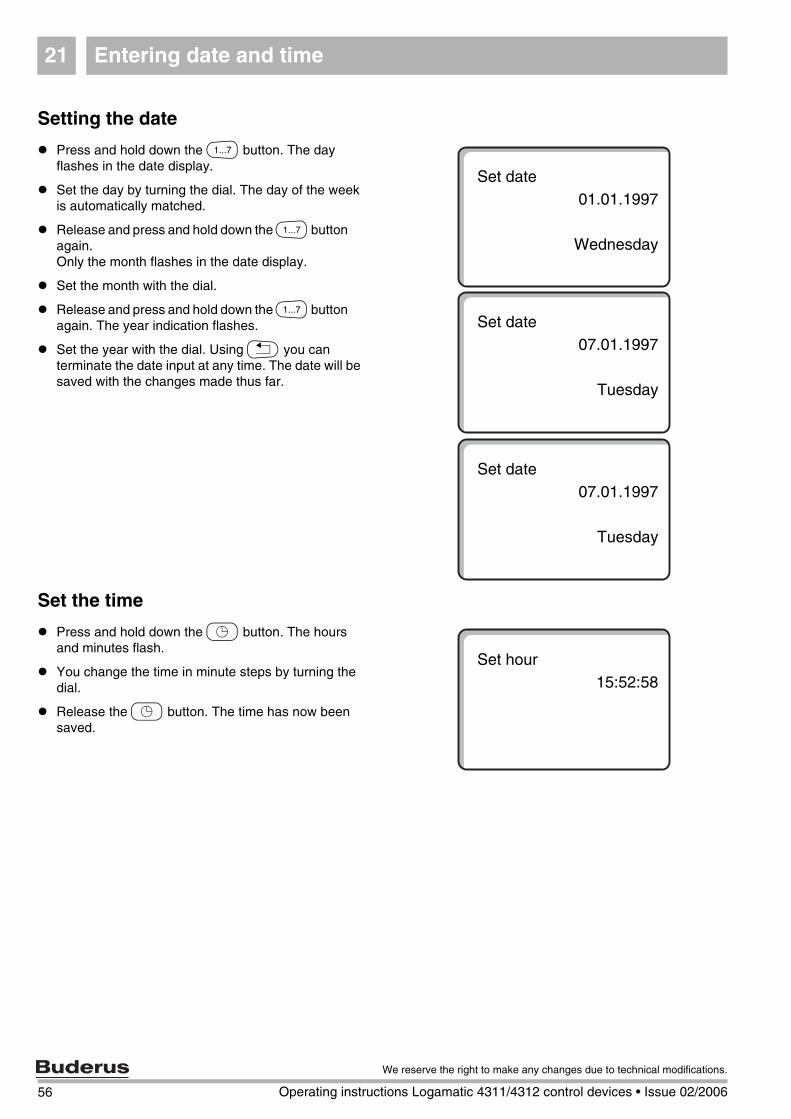
Setting the date
Press and hold down the M button. The day flashes in the date display.
Set the day by turning the dial. The day of the week is automatically matched.
Release and press and hold down the M button again.Only the month flashes in the date display.
Set the month with the dial.
Release and press and hold down the M button again. The year indication flashes.
Set the year with the dial. Using K you can terminate the date input at any time. The date will be saved with the changes made thus far.
Set the time
Press and hold down the L button. The hours and minutes flash.
You change the time in minute steps by turning the dial.
Release the L button. The time has now been saved.
Set date01.01.1997
Wednesday
Set date07.01.1997
Tuesday
Set date07.01.1997
Tuesday
Set hour15:52:58
56 Operating instructions Logamatic 4311/4312 control devices • Issue 02/2006
We reserve the right to make any changes due to technical modifications.
Flue gas test 22
57
We reserve the right to make any changes due to technical modifications.
Operating instructions Logamatic 4311/4312 control devices • Issue 02/2006
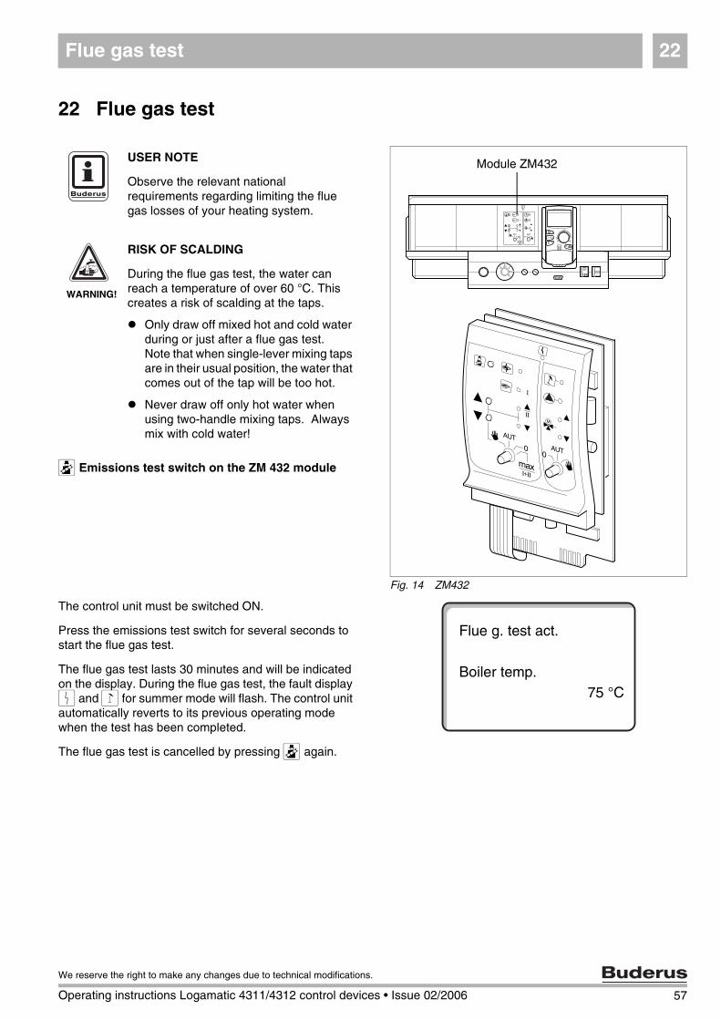
22 Flue gas test
Q Emissions test switch on the ZM 432 module
The control unit must be switched ON.
Press the emissions test switch for several seconds to start the flue gas test.
The flue gas test lasts 30 minutes and will be indicated on the display. During the flue gas test, the fault display 0 and 1 for summer mode will flash. The control unit automatically reverts to its previous operating mode when the test has been completed.
The flue gas test is cancelled by pressing Q again.
Fig. 14 ZM432
Module ZM432USER NOTE
Observe the relevant national requirements regarding limiting the flue gas losses of your heating system.
WARNING!
RISK OF SCALDING
During the flue gas test, the water can reach a temperature of over 60 °C. This creates a risk of scalding at the taps.
Only draw off mixed hot and cold water during or just after a flue gas test.Note that when single-lever mixing taps are in their usual position, the water that comes out of the tap will be too hot.
Never draw off only hot water when using two-handle mixing taps. Always mix with cold water!
Flue g. test act.
Boiler temp.75 °C
58 Operating instructions Logamatic 4311/4312 control devices • Issue 02/2006
We reserve the right to make any changes due to technical modifications.
Matching the room temperature sensor23
23 Matching the room temperature sensor
If the room temperature shown on the display varies from the actual temperature measured with a thermometer, the display value can be adjusted using "Calibration MEC".
Calibration effects a parallel offset of the heating curve.
The factory setting is 0 °C.
The setting range is +5 °C to -5 °C.
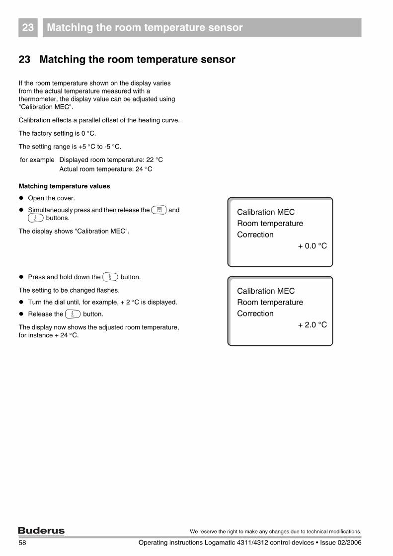
Matching temperature values
Open the cover.
Simultaneously press and then release the N and G buttons.
The display shows "Calibration MEC".
Press and hold down the G button.
The setting to be changed flashes.
Turn the dial until, for example, + 2 °C is displayed.
Release the G button.
The display now shows the adjusted room temperature, for instance + 24 °C.
for example Displayed room temperature: 22 °CActual room temperature: 24 °C
Calibration MECRoom temperatureCorrection
+ 0.0 °C
Calibration MECRoom temperatureCorrection
+ 2.0 °C
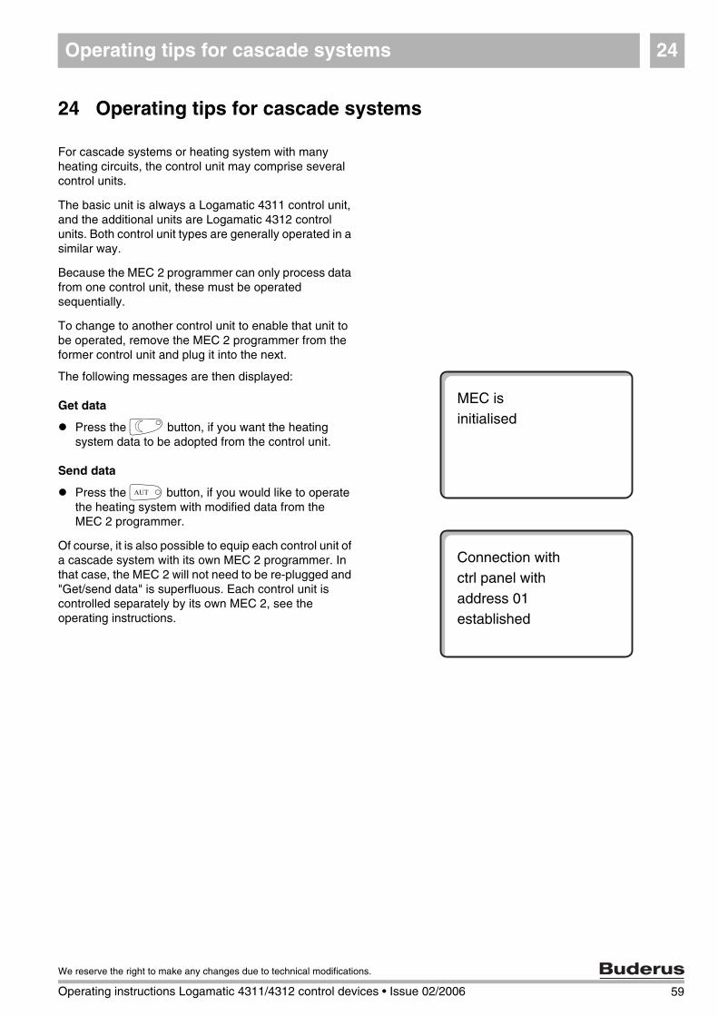
Operating tips for cascade systems 24
59
We reserve the right to make any changes due to technical modifications.
Operating instructions Logamatic 4311/4312 control devices • Issue 02/2006
24 Operating tips for cascade systems
For cascade systems or heating system with many heating circuits, the control unit may comprise several control units.
The basic unit is always a Logamatic 4311 control unit, and the additional units are Logamatic 4312 control units. Both control unit types are generally operated in a similar way.
Because the MEC 2 programmer can only process data from one control unit, these must be operated sequentially.
To change to another control unit to enable that unit to be operated, remove the MEC 2 programmer from the former control unit and plug it into the next.
The following messages are then displayed:
Get data
Press the F button, if you want the heating system data to be adopted from the control unit.
Send data
Press the D button, if you would like to operate the heating system with modified data from the MEC 2 programmer.
Of course, it is also possible to equip each control unit of a cascade system with its own MEC 2 programmer. In that case, the MEC 2 will not need to be re-plugged and "Get/send data" is superfluous. Each control unit is controlled separately by its own MEC 2, see the operating instructions.
MEC isinitialised
Connection withctrl panel withaddress 01established
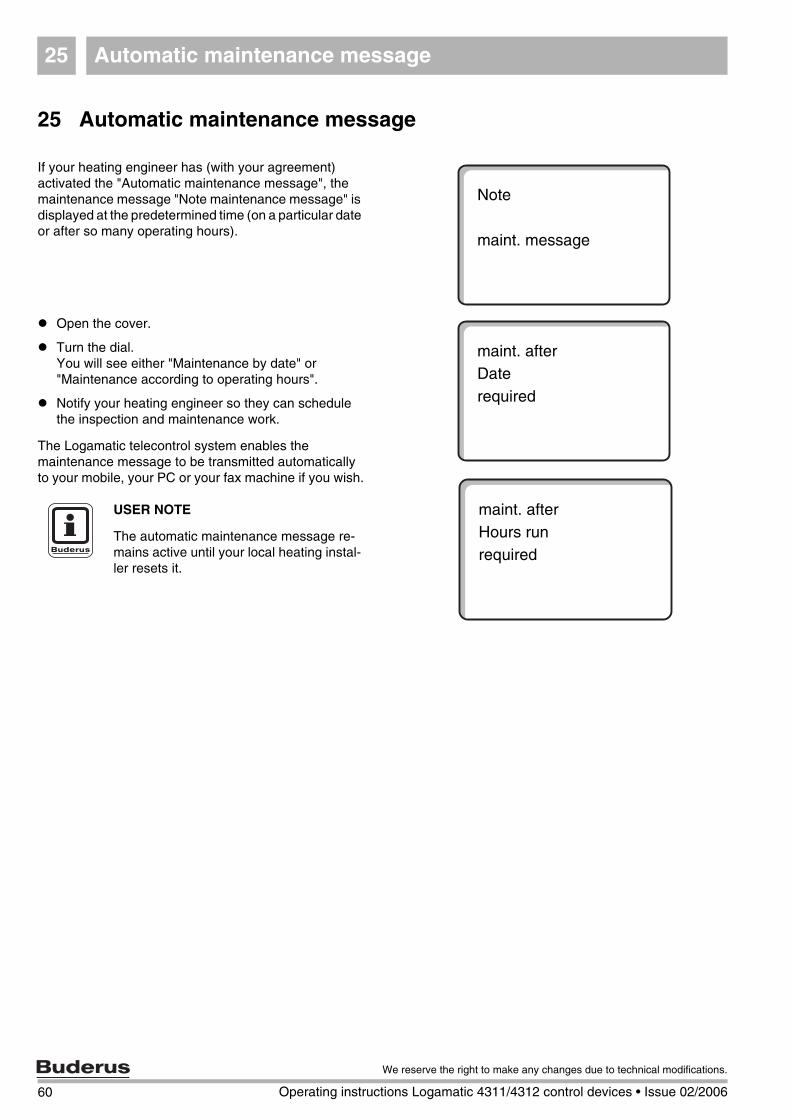
60 Operating instructions Logamatic 4311/4312 control devices • Issue 02/2006
We reserve the right to make any changes due to technical modifications.
Automatic maintenance message25
25 Automatic maintenance message
If your heating engineer has (with your agreement) activated the "Automatic maintenance message", the maintenance message "Note maintenance message" is displayed at the predetermined time (on a particular date or after so many operating hours).
Open the cover.
Turn the dial.You will see either "Maintenance by date" or "Maintenance according to operating hours".
Notify your heating engineer so they can schedule the inspection and maintenance work.
The Logamatic telecontrol system enables the maintenance message to be transmitted automatically to your mobile, your PC or your fax machine if you wish.
Note
maint. message
maint. after Daterequired
maint. after Hours runrequired
USER NOTE
The automatic maintenance message re-mains active until your local heating instal-ler resets it.
Troubleshooting 26
26 Troubleshooting
Faults and fault displays
Have your heating engineer remedy all faults immediately.
Report the fault initially by telephone to your heating installer. Set the control unit switch and those on the modules in accordance with chapter "Emergency operation". Heating system faults are shown on the display.
The following faults are shown:
– Burner fault boiler 1 – 3– Boiler temperature sensor– Outd. Temp. sensor– Heating circuit flow sensor
Heating circuit 1 – 8 (if installed)– DHW temperature sensor– Boiler stays cold– DHW remains cold– Remote control no communication with
heating circuit 1 – 8 (if installed)– Thermal disinfection– Auxiliary temperature sensor– Heating circuit 1 – 8 (if installed) pump fault– DHW pump fault– DHW inert anode fault– Safety equipment fault– No connection to the bus system– Address used more than once– System flow sensor– System return sensor– Boiler (1 – 3) not connected– External boiler fault– Flue gas sensor fault– Flue gas temperature exceeded– Address conflict slot 1 – 4 (if installed)– Incorrect module slot 1 – 4 (if installed)– Unknown module slot 1 – 4 (if installed)– Function module not connected– No master control unit installed– Solar cylinder X in manual mode
(not available in the UK)– Heating circuit X in manual mode– DHW in manual mode– Boiler circuit in manual mode– Burner in manual mode
61
We reserve the right to make any changes due to technical modifications.
Operating instructions Logamatic 4311/4312 control devices • Issue 02/2006
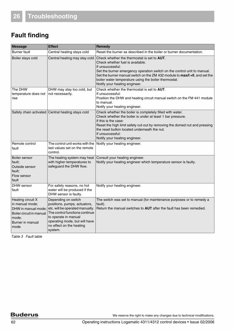
Troubleshooting26
Fault finding
Message Effect Remedy
Burner fault Central heating stays cold Reset the burner as described in the boiler or burner documentation.
Boiler stays cold Central heating may stay cold. Check whether the thermostat is set to AUT.Check whether fuel is available.If unsuccessful:Set the burner emergency operation switch on the control unit to manual.Set the burner manual switch on the ZM 432 module to max/I +II, and set the boiler water temperature using the boiler thermostat.Notify your heating engineer.
The DHW temperature does not rise
DHW may stay too cold, but not necessarily.
Check whether the thermostat is set to AUT.If unsuccessful:Position the DHW and heating circuit manual switch on the FM 441 module to manual.Notify your heating engineer.
Safety chain activated Central heating stays cold Check whether the boiler is completely filled with water.Check whether the boiler is under at least 1 bar pressure.If this is the case:Reset the high limit safety cut-out by removing the domed nut and pressing the reset button located underneath the nut.If unsuccessful:Notify your heating engineer.
Remote controlfault
The control unit works with the last values set on the remote control.
Notify your heating engineer.
Boiler sensorfault;Outside sensorfault;Flow sensorfault
The heating system may heat with higher temperatures to safeguard the DHW flow.
Consult your heating engineer.Notify your heating engineer which temperature sensor is faulty.
DHW sensorfault
For safety reasons, no hot water will be produced if the DHW sensor is faulty.
Notify your heating engineer.
Heating circuit Xin manual mode;DHW in manual mode;Boiler circuit in manual mode;Burner in manual mode
Depending on switch positions, pumps, actuators, etc. will be operated manually. The control functions continue to operate in manual operating mode, but will have no effect on the heating system.
The switch was set to manual (for maintenance purposes or to remedy a fault).Return the manual switches to AUT after the fault has been remedied.
Table 3 Fault table
62 Operating instructions Logamatic 4311/4312 control devices • Issue 02/2006
We reserve the right to make any changes due to technical modifications.
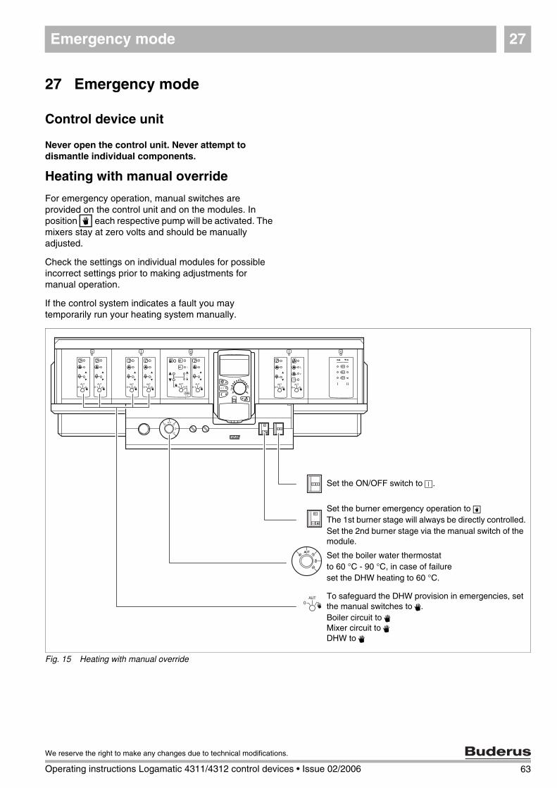
Emergency mode 27
27 Emergency mode
Control device unit
Never open the control unit. Never attempt to dismantle individual components.
Heating with manual override
For emergency operation, manual switches are provided on the control unit and on the modules. In position W each respective pump will be activated. The mixers stay at zero volts and should be manually adjusted.
Check the settings on individual modules for possible incorrect settings prior to making adjustments for manual operation.
If the control system indicates a fault you may temporarily run your heating system manually.
Fig. 15 Heating with manual override
Set the ON/OFF switch to R.
Set the burner emergency operation to WThe 1st burner stage will always be directly controlled.Set the 2nd burner stage via the manual switch of the module.
Set the boiler water thermostatto 60 °C - 90 °C, in case of failureset the DHW heating to 60 °C.
To safeguard the DHW provision in emergencies, set the manual switches to 3.Boiler circuit to 3Mixer circuit to 3DHW to 3
63
We reserve the right to make any changes due to technical modifications.
Operating instructions Logamatic 4311/4312 control devices • Issue 02/2006
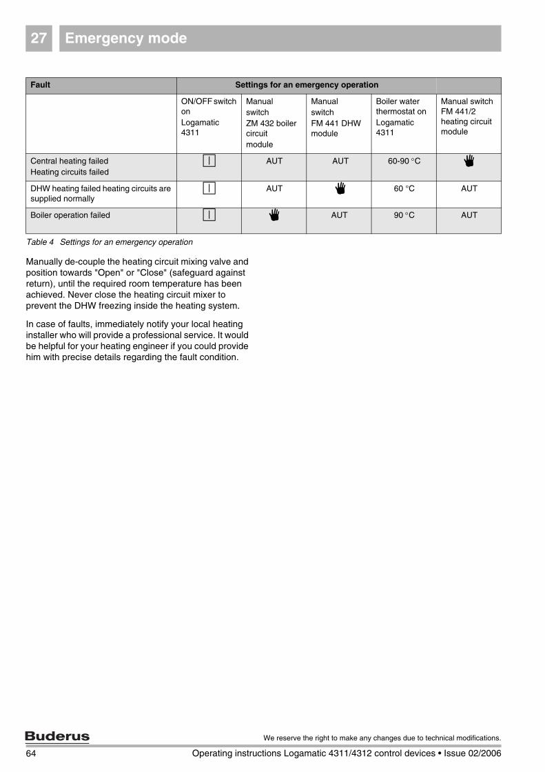
Emergency mode27
Manually de-couple the heating circuit mixing valve and position towards "Open" or "Close" (safeguard against return), until the required room temperature has been achieved. Never close the heating circuit mixer to prevent the DHW freezing inside the heating system.
In case of faults, immediately notify your local heating installer who will provide a professional service. It would be helpful for your heating engineer if you could provide him with precise details regarding the fault condition.
Fault Settings for an emergency operation
ON/OFF switch onLogamatic 4311
ManualswitchZM 432 boiler circuitmodule
Manualswitch FM 441 DHW module
Boiler water thermostat onLogamatic 4311
Manual switch FM 441/2 heating circuit module
Central heating failedHeating circuits failed
R AUT AUT 60-90 °C 3
DHW heating failed heating circuits are supplied normally
R AUT 3 60 °C AUT
Boiler operation failed R 3 AUT 90 °C AUT
Table 4 Settings for an emergency operation
64 Operating instructions Logamatic 4311/4312 control devices • Issue 02/2006
We reserve the right to make any changes due to technical modifications.
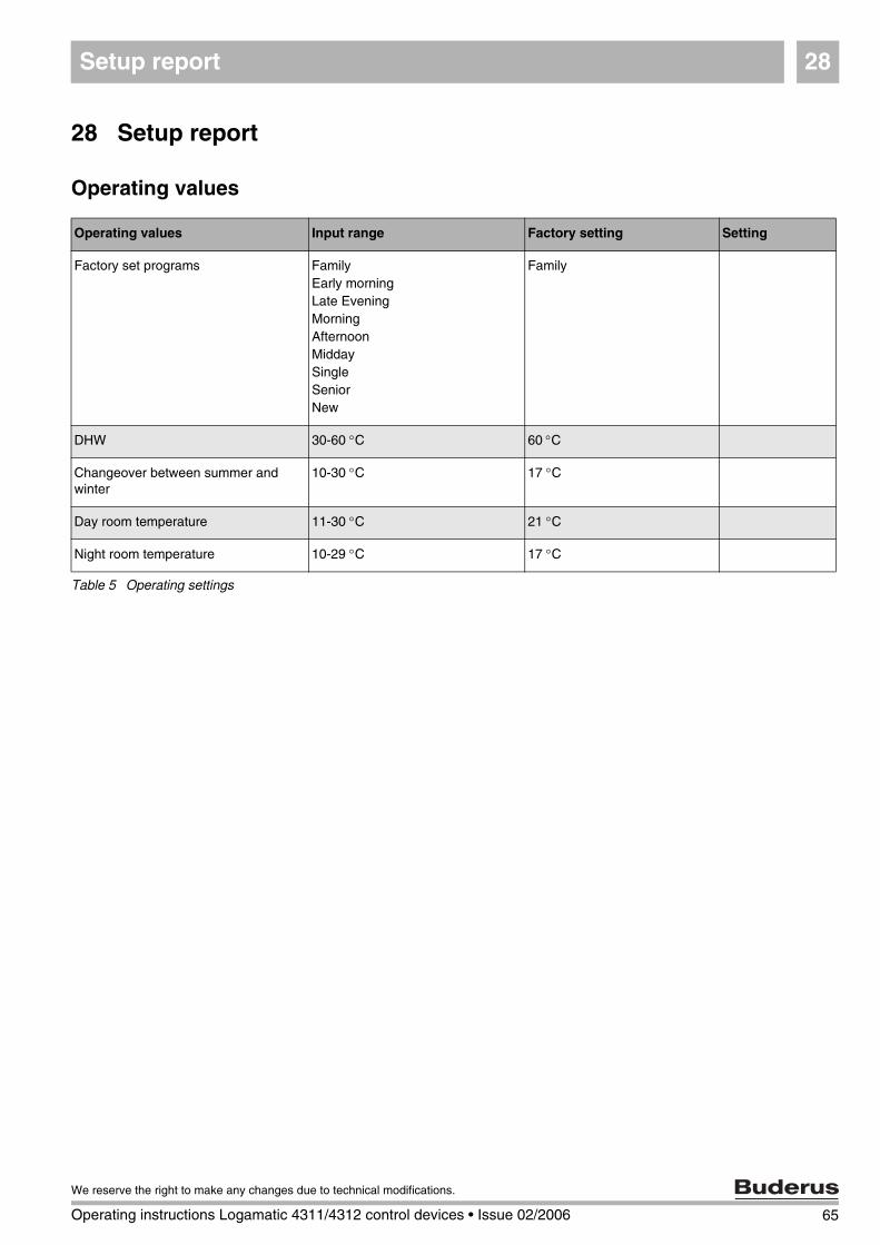
Setup report 28
65
We reserve the right to make any changes due to technical modifications.
Operating instructions Logamatic 4311/4312 control devices • Issue 02/2006
28 Setup report
Operating values
Operating values Input range Factory setting Setting
Factory set programs FamilyEarly morningLate EveningMorningAfternoonMiddaySingleSeniorNew
Family
DHW 30-60 °C 60 °C
Changeover between summer and winter
10-30 °C 17 °C
Day room temperature 11-30 °C 21 °C
Night room temperature 10-29 °C 17 °C
Table 5 Operating settings
Keyword Index29
66 Operating instructions Logamatic 4311/4312 control devices • Issue 02/2006
We reserve the right to make any changes due to technical modifications.
29 Keyword Index
AAutomatic changeover between summer and winter . . . . . . . . . . . . . . . . . . . . .52Automatic DHW operation . . . . . . . . . . . . .24
BBoiler . . . . . . . . . . . . . . . . . . . . . . . . 10Burner functions . . . . . . . . . . . . . . . . . .10Burner switch . . . . . . . . . . . . . . . . . . . . 10
CCascade systems . . . . . . . . . . . . . . . . . . 59Changeover between summer and winter . . . . . 18Changing the standard display . . . . . . . . . . .54Constant DHW circulation pump operation . . . . . 25Constant DHW operation . . . . . . . . . . . . . .24Controls . . . . . . . . . . . . . . . . . . . . . . . 8Creating a new heating program . . . . . . . . . . 42
DDay room temperature . . . . . . . . 16, 17, 20, 21DHW circulation pump . . . . . . . . . . . . .25, 45DHW control . . . . . . . . . . . . . . . . . . . .23DHW functions . . . . . . . . . . . . . . . . . . . 12Displays . . . . . . . . . . . . . . . . . . . . . .27Domestic hot water temperature . . . . . . . .17, 23
EEmergency mode fault . . . . . . . . . . . . . . .64Emissions test switch . . . . . . . . . . . . . . . . 57
FFault displays . . . . . . . . . . . . . . . . . . . . 61Fault finding . . . . . . . . . . . . . . . . . . . .62Flue gas test . . . . . . . . . . . . . . . . . .10, 57
HHeat economically . . . . . . . . . . . . . . . . . 7Heating circuit and DHW module . . . . . . . . . .12Heating circuit function . . . . . . . . . . . . . . .13Heating circuit functions . . . . . . . . . . . . . . 12Heating circuit module . . . . . . . . . . . . . . .13Heating with manual override . . . . . . . . . . . 63Holiday program . . . . . . . . . . . . . . . . . .48
IInitial start-up . . . . . . . . . . . . . . . . . . . . 16Inserted modules . . . . . . . . . . . . . . . . . . 8Interrupting a holiday program . . . . . . . . . . . 50
MMaintenance message . . . . . . . . . . . . . . .60Matching the room temperature sensor . . . . . .58Modules . . . . . . . . . . . . . . . . . . . . . . 9
NNew DHW program . . . . . . . . . . . . . . . . . 44Night room temperature . . . . . . . . . . . .17, 22
OOperating conditions . . . . . . . . . . . . . . . .18Operating settings . . . . . . . . . . . . . . .27, 65
PParty function . . . . . . . . . . . . . . . . . . . 46Pause function . . . . . . . . . . . . . . . . . . 47Program selection . . . . . . . . . . . . . . . . . 42
RRadio clock signal . . . . . . . . . . . . . . . . . 55Reloading DHW . . . . . . . . . . . . . . . . . . 23Room temperature . . . . . . . . . . . . . . . . 17
SSelect a heating circuit . . . . . . . . . . . . . . 42Selecting the standard program . . . . . . . . . 28Setting the changeover temperature . . . . . . . 52Setting the date . . . . . . . . . . . . . . . . . . 56Setting the room temperature . . . . . . . . . 16, 17Setting up summer mode . . . . . . . . . . . . . 53Setting winter mode . . . . . . . . . . . . . . . . 53Setup report . . . . . . . . . . . . . . . . . . . . 65Shutting down . . . . . . . . . . . . . . . . . . . 16Starting the DHW circulation pump . . . . . . . . 23Strategy module . . . . . . . . . . . . . . . . . 14Summary of standard programs . . . . . . . . . 31Summer mode . . . . . . . . . . . . . . . . . . 51Summer/winter changeover . . . . . . . . . . . . 51Switching OFF DHW heating . . . . . . . . . . . 24Switching OFF the DHW circulation pump . . . . 25
TThermal disinfection . . . . . . . . . . . . . . . 26

Notes
67
We reserve the right to make any changes due to technical modifications.
Operating instructions Logamatic 4311/4312 control devices • Issue 02/2006
Your installer:
BuderusCotswold Way, Warndon, Worcester WR4 9SW
Tel.: 01905 752794, Fax: 01905 753130www.buderus-commercial.co.uk
In the UK, Buderus is a trading name of BBT Thermotechnology Ltd.
BBT Thermotechnik GmbHD-35573 Wetzlar