local water management strategy macnaughton crescent... · management strategy lot 9021 macnaughton...
TRANSCRIPT
Local Water Management Strategy

Project number EP15-017 | October 2015 Page 1
LOCAL WATER MANAGEMENT STRATEGY LOT 9021 MACNAUGHTON CRESCENT LOCAL STRUCTURE PLAN, KINROSS Project Number EP15-017
Prepared for Peet Ltd October 2015

Project number EP15-017 | October 2015 Page i
Prepared for Peet Ltd Doc No.: EP15-017(03)--001B RLE | Revision: B
LOCAL WATER MANAGEMENT STRATEGY
LOT 9021 MACNAUGHTON CRESCENT LOCAL STRUCTURE PLAN, KINROSS
Document Control
DOC NAME LOT 9021 MACNAUGHTON CRESCENT LOCAL STRUCTURE PLAN KINROSS LWMS
DOC NO. EP15-017(03)--001 RLE
REVISION DATE AUTHOR REVIEWER
1 July 2015 Rachel Evans RLE Dave Coremans DPC
For issue to client
A October 2015 Rachel Evans RLE Dave Coremans DPC
For issue to CoJ
B October 2015 Rachel Evans RLE Dave Coremans DPC
For issue to CoJ
© 2015 Emerge Associates All Rights Reserved. Copyright in the whole and every part of this document belongs to Emerge Associates and may not be used, sold, transferred, copied or reproduced in whole or in part in any manner or form or in or on any media to any person without the prior written consent of Emerge Associates.
Project number EP15-017 | October 2015 Page ii
LOCAL WATER MANAGEMENT STRATEGY
Prepared for Peet Ltd Doc No.: EP15-017(03)--001B RLE | Revision: B
LOT 9021 MACNAUGHTON CRESCENT LOCAL STRUCTURE PLAN, KINROSS
Executive Summary
Peet Ltd (the ‘proponent’) proposes to develop Lot 9021 MacNaughton Crescent, Kinross (referred to herein as ‘the site’) for residential purposes. The site is situated 32 km north of Perth Central Business District, within the City of Joondalup (CoJ).
The site is currently zoned ‘Urban’ under the Metropolitan Region Scheme (MRS) and ‘Urban Development’ under the District Planning Scheme Number 2 (DPS 2).
The LWMS has been developed to support the Lot 9021 MacNaughton Crescent Local Structure Plan (LSP) in consideration of the objectives and principles detailed in ‘Better Urban Water Management’, State Planning Policy 2.9 Water Resources and Planning Bulletin 92 Urban Water Management. Water will be managed using an integrated water cycle approach, which has been developed using philosophies and design approaches described in the Stormwater Management Manual for Western Australia.
The first step in applying integrated water cycle management in urban catchments is to establish agreed environmental values for receiving waters and their ecosystems. Characteristics of the existing environment within the site have been investigated. In summary, the environmental investigations conducted to date indicate that:
The site receives 729 mm of average annual rainfall with the majority of rainfall received in June and July.
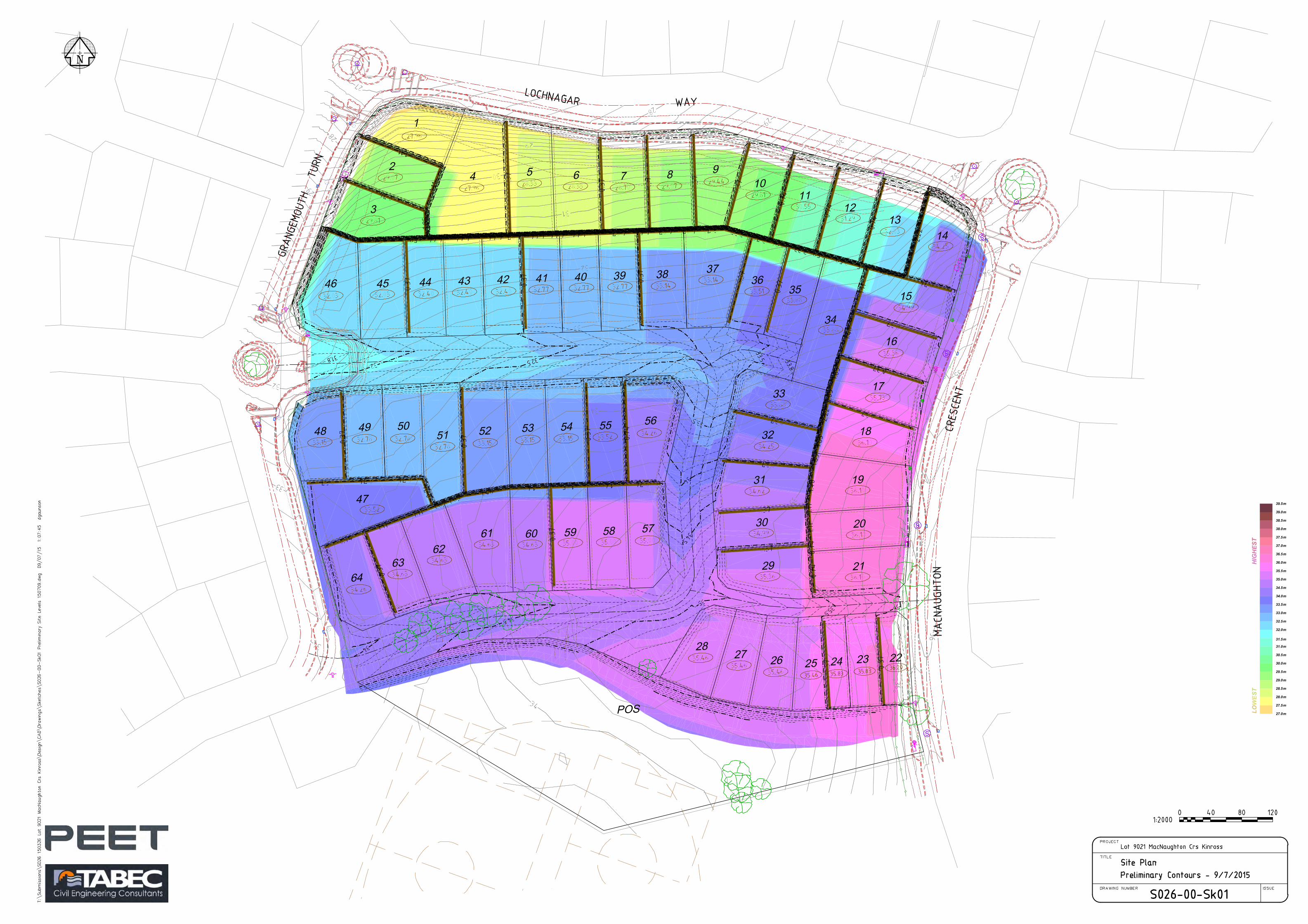
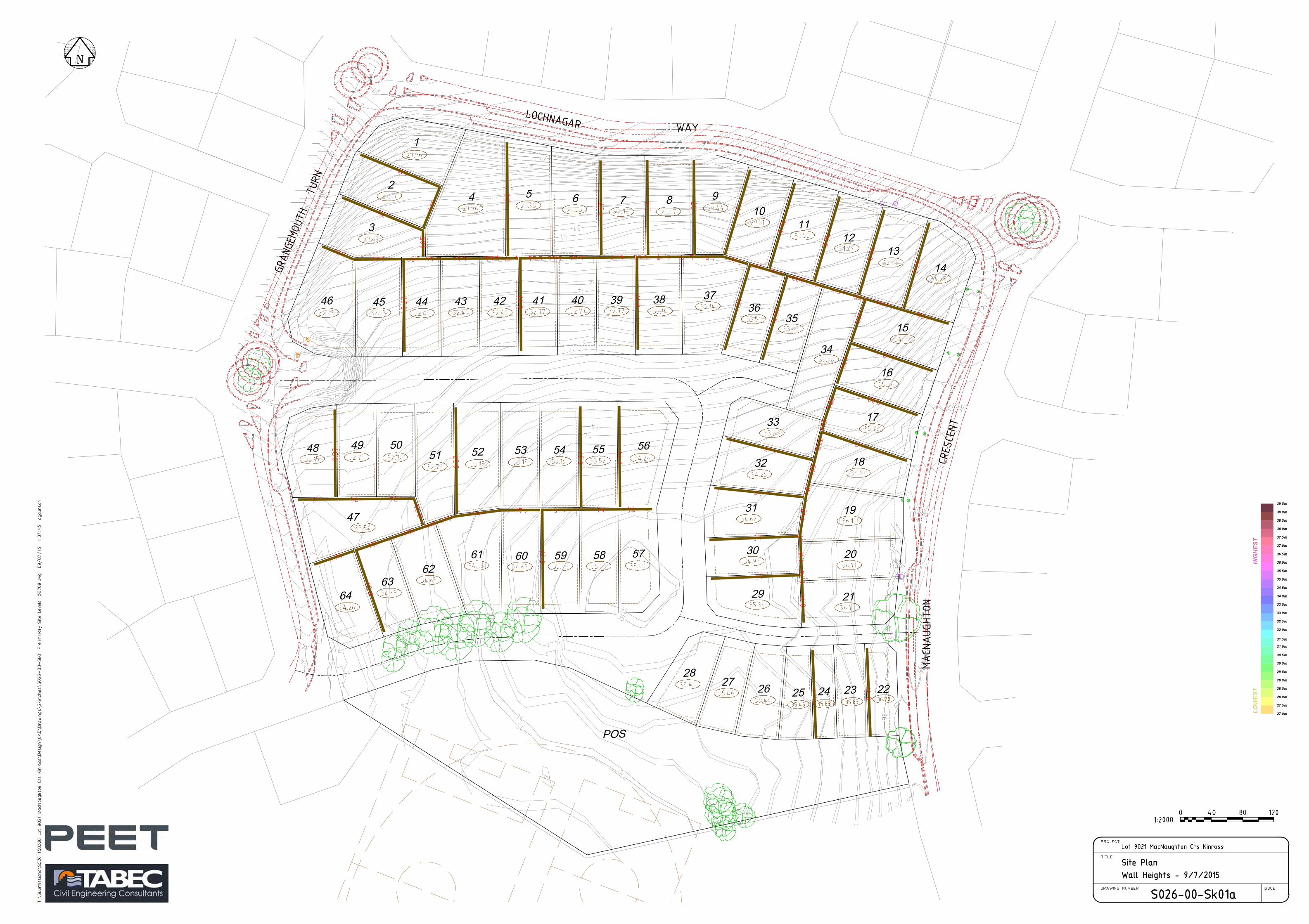
The site topography ranges between 29 and 36 m Australian height datum (AHD) with a general slope from south east to north west.
The majority of the site is underlain by Tamala Limestone, with a small portion of sand along the western boundary.
Acid sulfate soils (ASS) risk mapping classifies the entire site as having no known risk of encountering ASS within 3 m of the surface.
There are no wetlands within the site. High permeability of the underlying sands suggests that surface water is largely retained and
infiltrated within the site. The site is located in the Lochy Close sump catchment. A connection to the local drainage network exists immediately adjacent to the site at
Grangemouth Turn, opposite Ossian Way. No other connections have been allowed for in the existing and surrounding pipe design.
Depth to groundwater ranges between 25.5 m and 32.5 m with a historical maximum groundwater level (MGL) of approximately 3.5 m AHD. Groundwater underlying the site flows towards the Indian Ocean.
The site is currently vacant and unused with the exception of local recreation use such as dog walkers who utilise the site.
The Lot 9021 MacNaughton Crescent LSP covers approximately 4.02 ha and will allow for the creation of lot densities ranging between R20 and R40. The site incorporates 4,000 m2 of public open space (POS) which is located adjacent to the existing MacNaughton Park POS.
The overall objective for integrated water cycle management for the development is to mimic the existing hydrological regime of the site.

Project number EP15-017 | October 2015 Page iii
LOCAL WATER MANAGEMENT STRATEGY
Prepared for Peet Ltd Doc No.: EP15-017(03)--001B RLE | Revision: B
LOT 9021 MACNAUGHTON CRESCENT LOCAL STRUCTURE PLAN, KINROSS
The design objectives seek to deliver best practice outcomes using a Water Sensitive Urban Design (WSUD) approach, including management approaches for: Water conservation Stormwater quality management Flood mitigation Groundwater management. The criteria proposed within this LWMS are based on the characteristics of the existing environment and a contemporary best-practice approach to integrated water cycle management.
The overall approach to water conservation is to reduce the amount of scheme water required within the development at both a lot and estate scale. Within the lot, potable water consumption will be reduced by promoting water efficient fixtures and appliances (WEFA) and water wise gardening (WWG) principles within lot gardens. On an estate scale, groundwater will be utilised for irrigation of landscaped areas within POS areas which will also utilise WWG principles.
Surface water runoff will integrate with the existing local drainage network utilising existing infrastructure where available. Catchments that do not connect to the existing pipe network will retain the 5 year Average Recurrence Interval (ARI) event in a flood storage areas (FSA) located in POS. Lots will retain the 100 year ARI event on lot within soakwells and permeable areas, consistent with other developments in the local area.
Surface water quality will be addressed using a treatment train approach, which incorporates lot scale retention, sub-surface storage, a bio-retention area (BRA) within POS (for minor events). Further non-structural measures will also be adopted and will be detailed in the future Urban
Groundwater management focusses on protecting groundwater quality and recharging the aquifer. The substantial clearance to groundwater across the majority of the site and high permeability of the underlying soils indicates that inundation from groundwater is unlikely. Groundwater quality will be maintained by reducing total nutrient loads originating from the development, treating surface water runoff as close to source as possible and using high nutrient uptake soils and vegetation within drainage infrastructure. Measures to address groundwater quality are consistent with those proposed for surface water quality. Recharging the aquifer will be achieved through the retention and infiltration of runoff from lots at source through lot retention, sub-surface storage, a BRA and FSA.
The proposed criteria and the manner in which they are proposed to be achieved are presented in Table E1. This table provides a readily auditable summary of the required outcomes which can be used in the future detailed design stage to demonstrate that the agreed objectives for water management across the site have actually been achieved.
This LWMS demonstrates that by following the recommendations detailed in the report the site is capable of being developed.
Prepared for Peet Ltd Doc No.: EP15-017(03)--001B RLE | Revision: B
LOCAL WATER MANAGEMENT STRATEGY
LOT 9021 MACNAUGHTON CRESCENT LOCAL STRUCTURE PLAN, KINROSS
Project number: EP15-017 | October 2015 Page iv
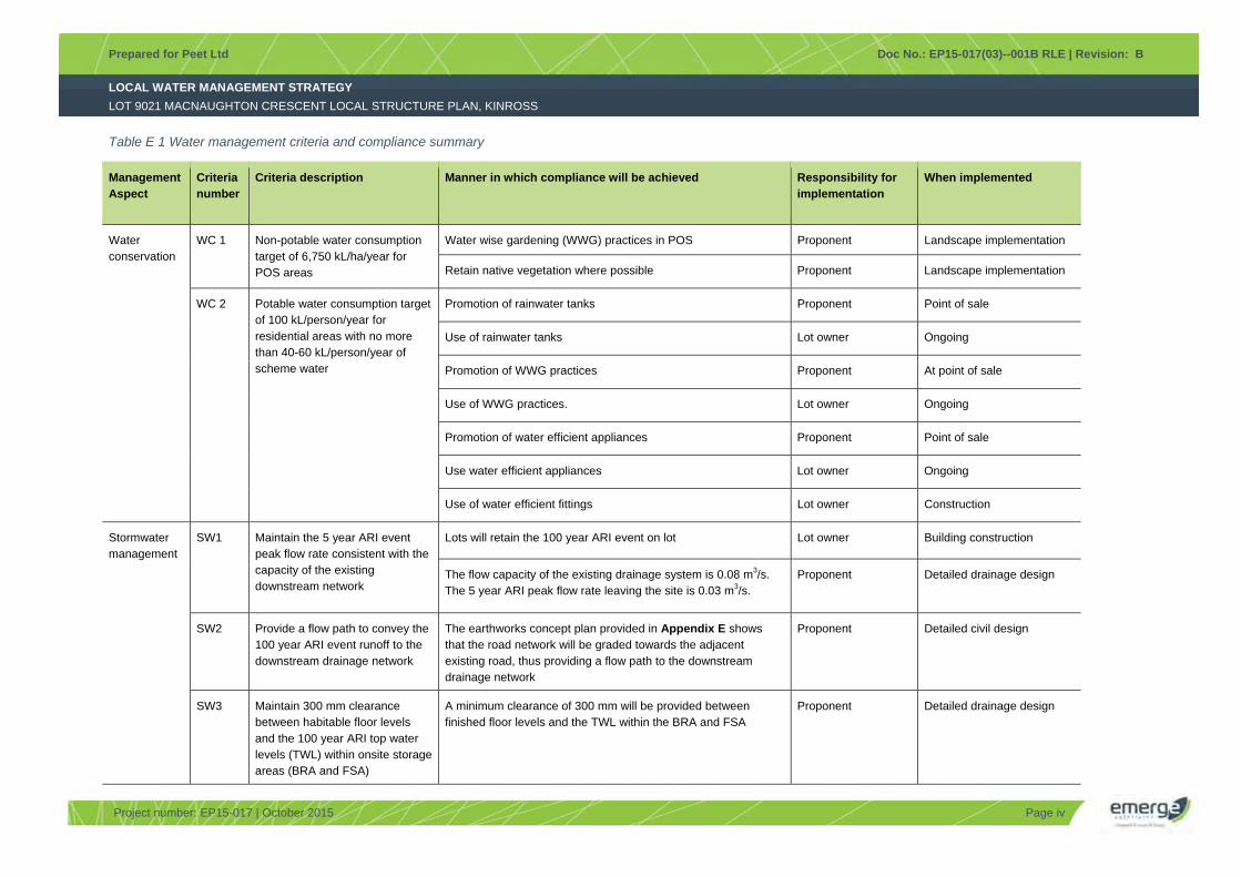
Table E 1 Water management criteria and compliance summary
Management Aspect
Criteria number
Criteria description Manner in which compliance will be achieved Responsibility for implementation
When implemented
Water conservation
WC 1 Non-potable water consumption target of 6,750 kL/ha/year for POS areas
Water wise gardening (WWG) practices in POS Proponent Landscape implementation
Retain native vegetation where possible Proponent Landscape implementation
WC 2 Potable water consumption target of 100 kL/person/year for residential areas with no more than 40-60 kL/person/year of scheme water
Promotion of rainwater tanks Proponent Point of sale
Use of rainwater tanks Lot owner Ongoing
Promotion of WWG practices Proponent At point of sale
Use of WWG practices. Lot owner Ongoing
Promotion of water efficient appliances Proponent Point of sale
Use water efficient appliances Lot owner Ongoing
Use of water efficient fittings Lot owner Construction
Stormwater management
SW1 Maintain the 5 year ARI event peak flow rate consistent with the capacity of the existing downstream network
Lots will retain the 100 year ARI event on lot Lot owner Building construction
The flow capacity of the existing drainage system is 0.08 m3/s. The 5 year ARI peak flow rate leaving the site is 0.03 m3/s.
Proponent Detailed drainage design
SW2 Provide a flow path to convey the 100 year ARI event runoff to the downstream drainage network
The earthworks concept plan provided in Appendix E shows that the road network will be graded towards the adjacent existing road, thus providing a flow path to the downstream drainage network
Proponent Detailed civil design
SW3 Maintain 300 mm clearance between habitable floor levels and the 100 year ARI top water levels (TWL) within onsite storage areas (BRA and FSA)
A minimum clearance of 300 mm will be provided between finished floor levels and the TWL within the BRA and FSA
Proponent Detailed drainage design
Prepared for Peet Ltd Doc No.: EP15-017(03)--001B RLE | Revision: B
LOCAL WATER MANAGEMENT STRATEGY
LOT 9021 MACNAUGHTON CRESCENT LOCAL STRUCTURE PLAN, KINROSS
Project number: EP15-017 | October 2015 Page v
Management Aspect
Criteria number
Criteria description Manner in which compliance will be achieved Responsibility for implementation
When implemented
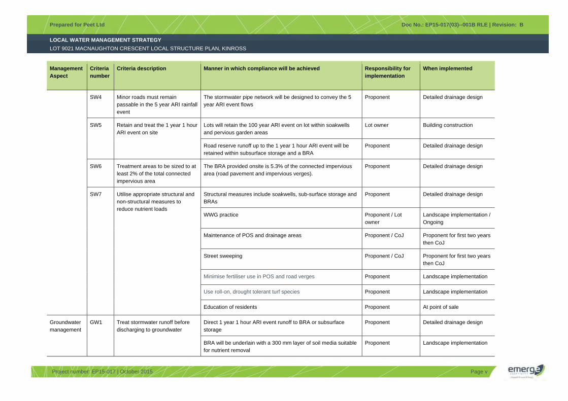
SW4 Minor roads must remain passable in the 5 year ARI rainfall event
The stormwater pipe network will be designed to convey the 5 year ARI event flows
Proponent Detailed drainage design
SW5 Retain and treat the 1 year 1 hour ARI event on site
Lots will retain the 100 year ARI event on lot within soakwells and pervious garden areas
Lot owner Building construction
Road reserve runoff up to the 1 year 1 hour ARI event will be retained within subsurface storage and a BRA
Proponent Detailed drainage design
SW6 Treatment areas to be sized to at least 2% of the total connected impervious area
The BRA provided onsite is 5.3% of the connected impervious area (road pavement and impervious verges).
Proponent Detailed drainage design
SW7 Utilise appropriate structural and non-structural measures to reduce nutrient loads
Structural measures include soakwells, sub-surface storage and BRAs
Proponent Detailed drainage design
WWG practice Proponent / Lot owner
Landscape implementation / Ongoing
Maintenance of POS and drainage areas Proponent / CoJ Proponent for first two years then CoJ
Street sweeping Proponent / CoJ Proponent for first two years then CoJ
Minimise fertiliser use in POS and road verges Proponent Landscape implementation
Use roll-on, drought tolerant turf species Proponent Landscape implementation
Education of residents Proponent At point of sale
Groundwater management
GW1 Treat stormwater runoff before discharging to groundwater
Direct 1 year 1 hour ARI event runoff to BRA or subsurface storage
Proponent Detailed drainage design
BRA will be underlain with a 300 mm layer of soil media suitable for nutrient removal
Proponent Landscape implementation
Prepared for Peet Ltd Doc No.: EP15-017(03)--001B RLE | Revision: B
LOCAL WATER MANAGEMENT STRATEGY
LOT 9021 MACNAUGHTON CRESCENT LOCAL STRUCTURE PLAN, KINROSS
Project number: EP15-017 | October 2015 Page vi
Management Aspect
Criteria number
Criteria description Manner in which compliance will be achieved Responsibility for implementation
When implemented
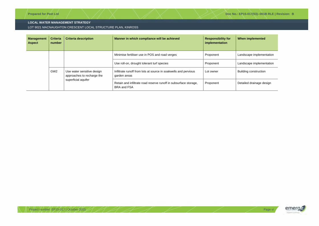
Minimise fertiliser use in POS and road verges Proponent Landscape implementation
Use roll-on, drought tolerant turf species Proponent Landscape implementation
GW2 Use water sensitive design approaches to recharge the superficial aquifer
Infiltrate runoff from lots at source in soakwells and pervious garden areas
Lot owner Building construction
Retain and infiltrate road reserve runoff in subsurface storage, BRA and FSA
Proponent Detailed drainage design
LOCAL WATER MANAGEMENT STRATEGY
Prepared for Peet Ltd Doc No.: EP15-017(03)--001B RLE | Revision: B
LOT 9021 MACNAUGHTON CRESCENT LOCAL STRUCTURE PLAN, KINROSS
Project number EP15-017 | October 2015 Page vii
Table of Contents
1 Introduction ............................................................................................................................................... 10 1.1 Background ..................................................................................................................................... 10 1.2 Town planning context..................................................................................................................... 10 1.3 Purpose of this report ...................................................................................................................... 10 1.4 Policy framework ............................................................................................................................. 10 1.5 LWMS objectives ............................................................................................................................. 11
2 Proposed Development ............................................................................................................................ 12
3 Pre-development Environment ................................................................................................................ 13 3.1 Sources of information..................................................................................................................... 13 3.2 Climate ............................................................................................................................................ 13 3.3 Geotechnical conditions .................................................................................................................. 13
3.3.1 Topography .................................................................................................................... 13 3.3.2 Soils ................................................................................................................................ 13 3.3.3 Acid sulfate soils ............................................................................................................. 13
3.4 Wetlands ......................................................................................................................................... 14 3.5 Hydrology ........................................................................................................................................ 14
3.5.1 Surface water quantity .................................................................................................... 14 3.5.2 Surface water quality ...................................................................................................... 14 3.5.3 Existing drainage ............................................................................................................ 14 3.5.4 Groundwater levels ......................................................................................................... 14 3.5.5 Groundwater quality ....................................................................................................... 15
3.6 Current and historical land uses ...................................................................................................... 15 3.7 Summary of existing environment ................................................................................................... 15
4 Design Criteria and Objectives ................................................................................................................ 16 4.1 Integrated water cycle management ............................................................................................... 16 4.2 Water conservation ......................................................................................................................... 16 4.3 Stormwater management ................................................................................................................ 17 4.4 Groundwater management .............................................................................................................. 17
5 Water Source Allocation, Infrastructure and Fit-For-Purpose .............................................................. 18 5.1 Fit for purpose water use ................................................................................................................. 18
5.1.1 Scheme water ................................................................................................................. 18 5.1.2 Groundwater ................................................................................................................... 18 5.1.3 Rainwater tanks .............................................................................................................. 18
5.2 Water conservation measures ......................................................................................................... 18 5.2.1 Rainwater tanks .............................................................................................................. 18 5.2.2 Water efficient fixtures and appliances ........................................................................... 19 5.2.3 Waterwise gardens ......................................................................................................... 19 5.2.4 Educational material ....................................................................................................... 19
5.3 Lot water balance ............................................................................................................................ 20 5.4 Estate scale water usage ................................................................................................................ 20 5.5 Wastewater management ................................................................................................................ 21 5.6 Water conservation criteria compliance summary ........................................................................... 21
6 Stormwater Management Strategy .......................................................................................................... 22 6.1 Stormwater management approach ................................................................................................ 22
6.1.1 Lot drainage.................................................................................................................... 22 6.1.2 Sub-surface storage ....................................................................................................... 22
LOCAL WATER MANAGEMENT STRATEGY
Prepared for Peet Ltd Doc No.: EP15-017(03)--001B RLE | Revision: B
LOT 9021 MACNAUGHTON CRESCENT LOCAL STRUCTURE PLAN, KINROSS
Project number EP15-017 | October 2015 Page viii
6.1.3 Bio-retention areas ......................................................................................................... 22 6.1.4 Flood storage areas ........................................................................................................ 23 6.1.5 Piped drainage network .................................................................................................. 23
6.2 Compliance summary ...................................................................................................................... 24
7 Groundwater Management Strategy ....................................................................................................... 25 7.1 Groundwater quality management .................................................................................................. 25 7.2 Groundwater criteria compliance summary ..................................................................................... 25
8 Matters to be addressed in the UWMP .................................................................................................... 27 8.1 Detailed drainage design ................................................................................................................. 27 8.2 Implementation of water conservation strategies ............................................................................ 27 8.3 Non-structural water quality improvement measures ...................................................................... 28 8.4 Management and maintenance requirements ................................................................................. 28 8.5 Construction period management strategy ...................................................................................... 28 8.6 Groundwater license status ............................................................................................................. 28 8.7 Subsurface infrastructure design ..................................................................................................... 28 8.8 Geotechnical report ......................................................................................................................... 29
9 Monitoring ................................................................................................................................................. 30 9.1 Condition monitoring ....................................................................................................................... 30 9.2 Reporting ......................................................................................................................................... 30
10 Implementation ......................................................................................................................................... 31 10.1 Roles and responsibility ................................................................................................................... 31 10.2 Funding ........................................................................................................................................... 31 10.3 Recommendations .......................................................................................................................... 31
11 References ................................................................................................................................................ 32 11.1 General references .......................................................................................................................... 32 11.2 Online references ............................................................................................................................ 33
List of Tables
Table 1 Lot 9021 MacNaughton Crescent LSP lot water consumption ....................................................... 20 Table 2 Water conservation criteria compliance ......................................................................................... 21 Table 3 Surface water management criteria compliance ............................................................................ 24 Table 4 Groundwater management criteria compliance ............................................................................. 25
Figures
Figure 1: Site location Figure 2: Site boundary Figure 3: Topography Figure 4: Geological mapping Figure 5: Stormwater management plan

LOCAL WATER MANAGEMENT STRATEGY
Prepared for Peet Ltd Doc No.: EP15-017(03)--001B RLE | Revision: B
LOT 9021 MACNAUGHTON CRESCENT LOCAL STRUCTURE PLAN, KINROSS
Project number EP15-017 | October 2015 Page ix
Appendices
Appendix A Local structure plan
Appendix B Landscape plans
Appendix C Existing drainage designs
Appendix D Modelling assumptions
Appendix E Earthworks plan

LOCAL WATER MANAGEMENT STRATEGY
Prepared for Peet Ltd Doc No.: EP15-017(03)--001B RLE | Revision: B
LOT 9021 MACNAUGHTON CRESCENT LOCAL STRUCTURE PLAN, KINROSS
Project number EP15-017 | October 2015 Page 10
1 Introduction
1.1 Background
Peet Ltd (the ‘proponent’) proposes to develop Lot 9021 MacNaughton Crescent, Kinross (referred to herein as ‘the site’) for residential purposes.
The site is situated 32 km north of Perth Central Business District, within the City of Joondalup (CoJ).
The location of the site is shown in Figure 1. An aerial photograph showing the current condition and cadastral boundaries of the site is also shown in Figure 2.
1.2 Town planning context
The site is located within a well-established residential area of Kinross. The site was set aside for a future primary school in the structure planning for the Kinross locality in the early 1990’s however the Department of Education subsequently determined that the site will not be required for a primary school.
The site is currently zoned ‘Urban’ under the Metropolitan Region Scheme (MRS) (WAPC 2015) and ‘Urban Development’ under the District Planning Scheme Number 2 (DPS 2) (CoJ 2015).
1.3 Purpose of this report
It is important that the manner in which stormwater runoff from urban zoned areas is to be managed to avoid flooding and protect the environment is clearly documented early in the planning process. This approach provides the framework for actions and measures to achieve the desired outcomes at subdivision and development stages. This Local Water Management Strategy (LWMS) details the water management approach to support the Lot 9021 MacNaughton Crescent Local Structure Plan (LSP area) and is intended to satisfy the requirement to prepare a LWMS in accordance with Better Urban Water Management (WAPC 2008).
1.4 Policy framework
There are a number of State and local Government policies of relevance to the site. These policies include:
State Water Strategy (Government of WA 2003a) State Planning Policy 2.9 Water Resources (WAPC 2006) Guidance Statement No. 33: Environmental Guidance for Planning and Development (EPA
2008) Liveable Neighbourhoods Edition 4 (WAPC 2007) Planning Bulletin No. 64: Acid Sulfate Soils (WAPC 2009) Gnangara Sustainability Strategy (Government of WA 2009) Local Planning Strategy (CoJ 2014).
In addition to the above policies, there are a number of published guidelines and standards available that provide direction regarding the water discharge characteristics that urban developments should aim to achieve.

LOCAL WATER MANAGEMENT STRATEGY
Prepared for Peet Ltd Doc No.: EP15-017(03)--001B RLE | Revision: B
LOT 9021 MACNAUGHTON CRESCENT LOCAL STRUCTURE PLAN, KINROSS
Project number EP15-017 | October 2015 Page 11
These are key inputs that relate either directly or indirectly to the site and include:
Better Urban Water Management (WAPC 2008) Australian Runoff Quality (Engineers Australia 2006) Australian Rainfall and Runoff (Engineers Australia 1987) Decision Process for Stormwater Management in Western Australia (DoW 2009) Stormwater Management Manual for Western Australia (DoW 2007) National Water Quality Management Strategy (ANZECC 2000) Development Design Specification JD5: Stormwater Drainage Design (CoJ 1998) Policy 6-3: Stormwater Drainage (CoJ 2007) Stormwater Management Policy (CoJ 2012) City Water Plan 2012-2015 (CoJ 2011).
The guidance documents listed indicate a need for accurate baseline data prior to urban development. This will ensure that any future development is able to fulfil the stormwater management requirements of the Department of Water (DoW) and engineering standards specified by the CoJ, but will also ensure that realistic water management criteria that are practically achievable are adopted.
1.5 LWMS objectives
This LWMS has been developed in consideration of the objectives and principles detailed in Better Urban Water Management (WAPC 2008). It is intended to support the Lot 9021 MacNaughton Crescent LSP and is further based on the following major objectives:
Provide a broad level stormwater management framework to support future urban development. Incorporate appropriate best management practices (BMPs) into the drainage system that
address the environmental and stormwater management issues identified. Minimise development construction costs, which will result in reduced land costs for future
home owners. Minimise ongoing operation and maintenance costs for the land owners and CoJ. Develop a water supply and conservation strategy for the site that will aim to meet water use
targets. Protect water quality to the underlying aquifer. Protect existing and proposed residences from flood risk. Gain support from DoW and CoJ for the proposed method to manage stormwater within the site
and potential impacts on downstream areas.
Detailed objectives for water management within the site are further discussed in Section 4.

LOCAL WATER MANAGEMENT STRATEGY
Prepared for Peet Ltd Doc No.: EP15-017(03)--001B RLE | Revision: B
LOT 9021 MACNAUGHTON CRESCENT LOCAL STRUCTURE PLAN, KINROSS
Project number EP15-017 | October 2015 Page 12
2 Proposed Development
The Lot 9021 MacNaughton Crescent LSP covers approximately 4.02 ha and will allow for the creation of lot densities ranging from R20 to R40. The site incorporates 4,000 m2 of public open space (POS) which is located adjacent to the existing MacNaughton Park POS.
Stormwater from the site will be catered for through a combination of onsite detention, retention and connection to the existing local drainage network (discussed further in Sections 3.5.3 and 6).
The Lot 9021 MacNaughton Crescent LSP is shown in Appendix A. Landscape concept plans illustrating the integration with the adjacent MacNaughton POS and proposed drainage infrastructure are provided in Appendix B.

LOCAL WATER MANAGEMENT STRATEGY
Prepared for Peet Ltd Doc No.: EP15-017(03)--001B RLE | Revision: B
LOT 9021 MACNAUGHTON CRESCENT LOCAL STRUCTURE PLAN, KINROSS
Project number EP15-017 | October 2015 Page 13
3 Pre-development Environment
3.1 Sources of information
The following sources of information were used to provide a broad regional environmental context to the site:
National Water Quality Management Strategy (NWQMS) (ANZECC 2000) Perth Metropolitan Region 1:50, 000 Environmental Geology Series (Gozzard 1982) WA Atlas (Landgate 2015) Water Register (DoW 2015b) Perth Groundwater Atlas (DoW 2015a) Weather and Climate Statistics data (Bureau of Meteorology 2015).
In addition to the above information, site-specific investigations have been conducted aimed at providing more detail to the existing regional information. These site-specific investigations include an Environmental assessment and management strategy (Emerge Associates 2015) and site visits carried out by Emerge Associates in 2015 to ascertain any existing hydrological constraints. This is important, as it can have implications for the stormwater management measures and the extent of earthworks that may be required to facilitate subdivision.
3.2 Climate
The site experiences a dry Mediterranean climate of hot dry summers and cool wet winters. Long term climatic averages indicate that the site is located in an area of moderate to high rainfall, receiving 728 mm on average annually (Bureau of Meteorology 2015) with the majority of rainfall received in June and July. The region experiences rainfall for 80 days annually (on average).
3.3 Geotechnical conditions
3.3.1 Topography
The site ranges from 29 m AHD in the north west corner to 36 m AHD in the south east corner, as shown in Figure 3.
3.3.2 Soils
The Yanchep sheet of the 1:50,000 scale Environmental Geology series map (Gozzard 1982) indicates that the area is largely underlain with Tamala Limestone (LS1) with a small portion of Sand (S1) along the western boundary.
Geological mapping for the site is shown in Figure 4.
3.3.3 Acid sulfate soils
The WA Atlas (Landgate 2015) Acid Sulfate Soil (ASS) risk mapping classifies the entire site as having ‘no known risk of ASS occurring within 3 m of natural soil surface’.
LOCAL WATER MANAGEMENT STRATEGY
Prepared for Peet Ltd Doc No.: EP15-017(03)--001B RLE | Revision: B
LOT 9021 MACNAUGHTON CRESCENT LOCAL STRUCTURE PLAN, KINROSS
Project number EP15-017 | October 2015 Page 14
3.4 Wetlands
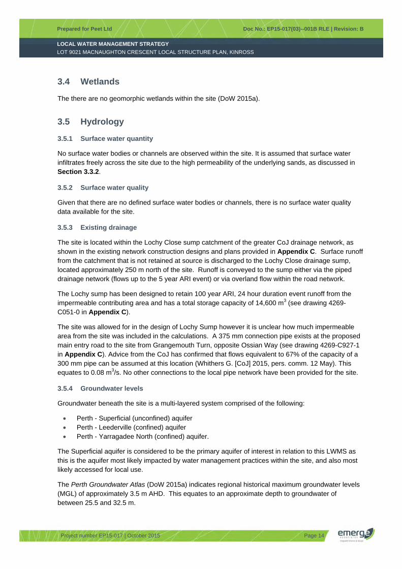
The there are no geomorphic wetlands within the site (DoW 2015a).
3.5 Hydrology
3.5.1 Surface water quantity
No surface water bodies or channels are observed within the site. It is assumed that surface water infiltrates freely across the site due to the high permeability of the underlying sands, as discussed in Section 3.3.2.
3.5.2 Surface water quality
Given that there are no defined surface water bodies or channels, there is no surface water quality data available for the site.
3.5.3 Existing drainage
The site is located within the Lochy Close sump catchment of the greater CoJ drainage network, as shown in the existing network construction designs and plans provided in Appendix C. Surface runoff from the catchment that is not retained at source is discharged to the Lochy Close drainage sump, located approximately 250 m north of the site. Runoff is conveyed to the sump either via the piped drainage network (flows up to the 5 year ARI event) or via overland flow within the road network.
The Lochy sump has been designed to retain 100 year ARI, 24 hour duration event runoff from the impermeable contributing area and has a total storage capacity of 14,600 m3 (see drawing 4269-C051-0 in Appendix C).
The site was allowed for in the design of Lochy Sump however it is unclear how much impermeable area from the site was included in the calculations. A 375 mm connection pipe exists at the proposed main entry road to the site from Grangemouth Turn, opposite Ossian Way (see drawing 4269-C927-1 in Appendix C). Advice from the CoJ has confirmed that flows equivalent to 67% of the capacity of a 300 mm pipe can be assumed at this location (Whithers G. [CoJ] 2015, pers. comm. 12 May). This equates to 0.08 m3/s. No other connections to the local pipe network have been provided for the site.
3.5.4 Groundwater levels
Groundwater beneath the site is a multi-layered system comprised of the following:
Perth - Superficial (unconfined) aquifer Perth - Leederville (confined) aquifer Perth - Yarragadee North (confined) aquifer.
The Superficial aquifer is considered to be the primary aquifer of interest in relation to this LWMS as this is the aquifer most likely impacted by water management practices within the site, and also most likely accessed for local use.
The Perth Groundwater Atlas (DoW 2015a) indicates regional historical maximum groundwater levels (MGL) of approximately 3.5 m AHD. This equates to an approximate depth to groundwater of between 25.5 and 32.5 m.
LOCAL WATER MANAGEMENT STRATEGY
Prepared for Peet Ltd Doc No.: EP15-017(03)--001B RLE | Revision: B
LOT 9021 MACNAUGHTON CRESCENT LOCAL STRUCTURE PLAN, KINROSS
Project number EP15-017 | October 2015 Page 15
3.5.5 Groundwater quality
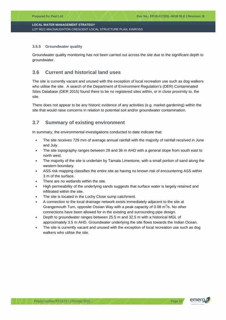
Groundwater quality monitoring has not been carried out across the site due to the significant depth to groundwater.
3.6 Current and historical land uses
The site is currently vacant and unused with the exception of local recreation use such as dog walkers who utilise the site. A search of the Department of Environment Regulation’s (DER) Contaminated Sites Database (DER 2015) found there to be no registered sites within, or in close proximity to, the site.
There does not appear to be any historic evidence of any activities (e.g. market gardening) within the site that would raise concerns in relation to potential soil and/or groundwater contamination.
3.7 Summary of existing environment
In summary, the environmental investigations conducted to date indicate that:
The site receives 729 mm of average annual rainfall with the majority of rainfall received in June and July.
The site topography ranges between 29 and 36 m AHD with a general slope from south east to north west.
The majority of the site is underlain by Tamala Limestone, with a small portion of sand along the western boundary.
ASS risk mapping classifies the entire site as having no known risk of encountering ASS within 3 m of the surface.
There are no wetlands within the site. High permeability of the underlying sands suggests that surface water is largely retained and
infiltrated within the site. The site is located in the Lochy Close sump catchment. A connection to the local drainage network exists immediately adjacent to the site at
Grangemouth Turn, opposite Ossian Way with a peak capacity of 0.08 m3/s. No other connections have been allowed for in the existing and surrounding pipe design.
Depth to groundwater ranges between 25.5 m and 32.5 m with a historical MGL of approximately 3.5 m AHD. Groundwater underlying the site flows towards the Indian Ocean.
The site is currently vacant and unused with the exception of local recreation use such as dog walkers who utilise the site.

LOCAL WATER MANAGEMENT STRATEGY
Prepared for Peet Ltd Doc No.: EP15-017(03)--001B RLE | Revision: B
LOT 9021 MACNAUGHTON CRESCENT LOCAL STRUCTURE PLAN, KINROSS
Project number EP15-017 | October 2015 Page 16
4 Design Criteria and Objectives
This section outlines the objectives and design criteria that this LWMS and future management plans must achieve. The water management strategy covers water consumption, groundwater management and stormwater management.
4.1 Integrated water cycle management
The State Water Strategy (Government of WA 2003b) endorses the promotion of integrated water cycle management and application of Water Sensitive Urban Design (WSUD) principles to provide improvements in the management of stormwater, and to increase the efficient use of other existing water supplies.
The key principles of integrated water cycle management include:
Considering all water sources, including wastewater, stormwater and groundwater Integrating water and land use planning Allocating and using water sustainably and equitably Integrating water use with natural water processes Adopting a whole of catchment integration of natural resource use and management.
Integrated water cycle management addresses not only physical and environmental aspects of water resource use and planning, but also integrates other social and economic concerns. Stormwater management design objectives should therefore seek to deliver best practice outcomes in terms of:
Potable water supply and consumption Flood mitigation Groundwater management.
The first step in applying integrated water cycle management in residential catchments is to establish agreed environmental values for receiving environments. The existing environmental context of the site has been discussed in Section 3 of this document. Guidance regarding environmental values and criteria is provided by a number of National and State policies and guidelines and site specific studies undertaken in and around the site development. These were detailed in Sections 1.4 and 3.1.
The design criteria discussed in the following sections are based on the assessment of the existing environment within the site, with the aim of achieving the integrated water cycle outcomes discussed above.
4.2 Water conservation
This LWMS proposes the following water conservation criteria:
Criteria WC 1 Non-potable water consumption target of 6,750 kL/ha/year for POS areas.
Criteria WC 2 Potable water consumption target of 100 kL/person/year for residential areas with no more than 40-60 kL/person/year of scheme water.
The manner in which these objectives will be achieved is further detailed in Section 5.
LOCAL WATER MANAGEMENT STRATEGY
Prepared for Peet Ltd Doc No.: EP15-017(03)--001B RLE | Revision: B
LOT 9021 MACNAUGHTON CRESCENT LOCAL STRUCTURE PLAN, KINROSS
Project number EP15-017 | October 2015 Page 17
4.3 Stormwater management
The principle behind stormwater management at the site is to mimic the pre-development hydrological conditions, as described in Section 3.5. This principle and the guidance documents discussed in Section 3 have guided the surface water management criteria.
This LWMS proposes the following stormwater design criteria:
Criteria SW1 Maintain the 5 year ARI event peak flow rate consistent with the capacity of the existing downstream network.
Criteria SW2 Provide a flow path to convey the 100 year ARI event runoff to the downstream drainage network.
Criteria SW3 Maintain 300 mm clearance between habitable floor levels and the 100 year ARI top water levels (TWL) within onsite storage areas (bio-retention areas (BRAs) and flood storage areas (FSAs)).
Criteria SW4 Minor roads must remain passable in the 5 year ARI rainfall event.
Criteria SW5 Retain and treat the 1 year 1 hour ARI event onsite.
Criteria SW6 BRAs to be sized to at least 2% of the total connected impervious area.
Criteria SW7 Utilise appropriate structural and non-structural measures to reduce nutrient loads.
The manner in which these objectives will be achieved is further detailed in Section 6.
4.4 Groundwater management
The principle behind the groundwater management strategy is to maintain the existing groundwater hydrology. Due to the significant depth to groundwater (as detailed in Section 3.5.4) the groundwater management criteria are integrally linked to stormwater management. This LWMS proposes the following groundwater management criteria:
Criteria GW1: Treat stormwater runoff before discharging to groundwater.
Criteria GW2: Use water sensitive design approaches to recharge the superficial aquifer.
The manner in which these objectives will be achieved is further detailed in Section 7. The management approach to achieve groundwater quality aims are consistent with those proposed for surface water. In order to reduce unnecessary duplication these management approaches are not proposed as groundwater criteria.

LOCAL WATER MANAGEMENT STRATEGY
Prepared for Peet Ltd Doc No.: EP15-017(03)--001B RLE | Revision: B
LOT 9021 MACNAUGHTON CRESCENT LOCAL STRUCTURE PLAN, KINROSS
Project number EP15-017 | October 2015 Page 18
5 Water Source Allocation, Infrastructure and Fit-For-Purpose
5.1 Fit for purpose water use
Conservation of water through fit-for-purpose use and best management practices is encouraged so that scheme water is not wasted. Fit-for-purpose principles have been utilised in the water conservation strategy for the site.
5.1.1 Scheme water
The site is located within, and will connect to, the Water Corporation (WC) integrated water supply scheme (IWSS) network. Scheme water is proposed to be used for all in-house potable uses, and where ex-house uses cannot be serviced by other supplies or approaches, it would also satisfy ex-house requirements.
5.1.2 Groundwater
Groundwater is proposed to be used for irrigation of POS areas. Assuming an average irrigation rate of 6,750 kL/ha/year, a total 2,700 kL/year will be required to irrigate the POS area. The status of groundwater allocation applications is detailed in Section 5.4.
5.1.3 Rainwater tanks
Harvested rainwater can be used in lots for some irrigation requirements however this will need to be supplemented with scheme water during the lower rainfall months. During the higher rainfall months, the majority of the harvested rainwater could be used to supplement internal building non-potable uses.
The use of rainwater tanks will not be mandated with the development however they will be promoted by the proponent at point of sale.
5.2 Water conservation measures
The development will utilise groundwater for POS irrigation, active POS irrigation management, Rainwater Tanks (RWT), waterwise gardening (WWG) principles for lot scale gardens and within estate landscaping and Water Efficient Fixtures and Appliances (WEFA) to ensure that the development minimises the use of water. Details of these measures are further discussed in the following sections.
5.2.1 Rainwater tanks
This water efficiency strategy recommends that the rainwater is used in washing machines, toilets and hot water systems where rainwater tanks are implemented. The stormwater quantity management strategy does not rely on the use of rainwater tanks, and they are therefore only considered to be a water conservation measure. It is assumed (for the purposes of the water balance analysis) that, where installed, rainwater tanks will have at least 3 kL of storage capacity. The lot water balance described in Section 5.3 assumes an uptake rate of 9 %, informed by ABS studies (ABS 2013b).

LOCAL WATER MANAGEMENT STRATEGY
Prepared for Peet Ltd Doc No.: EP15-017(03)--001B RLE | Revision: B
LOT 9021 MACNAUGHTON CRESCENT LOCAL STRUCTURE PLAN, KINROSS
Project number EP15-017 | October 2015 Page 19
5.2.2 Water efficient fixtures and appliances
Significant reduction in in-house water uses will be achieved with the use of water efficient fixtures and appliances (WEFA) (WC 2003).
The water conservation strategy assumes that all dwellings will use water efficient fixtures and that approximately 35% of homes will install water efficient appliances (ABS 2013b). The uptake of water efficient fixtures will be mandated through the building licence, while the uptake of water efficient appliances will be encouraged by state government rebates, as well as education from the proponent at point of sale. Further details will be provided within the future UWMP.
5.2.3 Waterwise gardens
Reductions in water use for irrigation by employing water efficiency measures can significantly reduce the total water usage (WC 2003). The development will undertake a variety of measures to limit water use into the future within POS and the private residential landscape works under the control of the proponent. A variety of methods and approaches will be considered including any or all of the following:
The adoption of water wise species, with a focus on using local native species or if necessary species from regions with similar climates.
Where required, existing site soil may be improved with soil conditioner certified to Australian Standard AS 4454 to a minimum depth of 150 mm where turf is to be planted and a minimum depth of 300 mm for garden beds.
The irrigation system is proposed to be designed and installed according to best water efficient practices including consideration of hydro zone design solutions.
The amount of turfed areas will be controlled while also being designed to meet community needs.
Garden beds will be mulched to 75 mm with a product certified to Australian Standard AS 4454. The POS design will cater for efficient water requirements during maintenance. This will be
achieved by implementing an appropriate management and maintenance program for POS areas that will be further detailed at the UWMP (Urban Water Management Plan) stage.
WWG principles will be implemented within the POS and road verges. Lot owners will be provided front of lot landscape packages with a requirement to implement WWG principles. In relation to the lot water balance discussed in Section 5.3, WWG principles have been assumed to be utilised in 75% of private lots (as informed by relevant studies (ABS 2013b) and provision of front of lot landscape packages).
5.2.4 Educational material
Educational material will be provided to lot purchasers to provide information on water efficiency and quality protection measures that they can implement within lots. Specific water conservation and protection topics that will be addressed include:
Water use reduction Water efficient technologies Recycling systems Fertiliser use Planting species.

LOCAL WATER MANAGEMENT STRATEGY
Prepared for Peet Ltd Doc No.: EP15-017(03)--001B RLE | Revision: B
LOT 9021 MACNAUGHTON CRESCENT LOCAL STRUCTURE PLAN, KINROSS
Project number EP15-017 | October 2015 Page 20
Provision of educational material will assist in achieving Criteria WC2 and GW3.
5.3 Lot water balance
A water balance analysis has been undertaken to demonstrate the effectiveness of the water conservation strategy proposed. The analysis considers realistic uptakes of non-mandatory water conservation measures including WEFA, RWTs and WWG. Uptake rate and population assumptions are calculated using data from the Australian Bureau of Statistics (ABS) (ABS 2013b, a). A comparison with a scenario where 100% of all proposed measures are utilised is also provided.
1. Scenario 1 – % uptake of water conservation strategy (WCS) (75% WWG, 9% RWT, 100% WE Fixtures, 35% WE Appliances)
2. Scenario 2 – Full WCS (100% of all measures).
The water balance analysis has been based on the rates and calculation methodology presented in the Water Corporation Spreadsheet AltWaterSupply_Water_Use_Model.xls (WC 2011). The water balance analysis assumes an average of 2.6 people per lot for single dwellings. Values are calculated from data provided by the ABS for new housing developments in Perth (ABS 2013a). This spreadsheet has been adapted to model the effects of using RWT, WWG and WEFA. The lot scale water consumption comparison for the two water conservation scenarios is presented in Table 1.
Table 1 Lot 9021 MacNaughton Crescent LSP lot water consumption
Scheme Scenario 1
% uptake of WCS Scenario 2 Full WCS
Total scheme water required (ML/year) 24.8 20.8
Scheme water per capita (kL/year/person) 52.4 26.2
The results of the water balance indicate that on average, if households in the development adopt the proposed water conservation measures at typical uptake rates, they will use 52.4 kL/year/person. This achieves the state water consumption target of no more than 100 kL/year/person and the Better Urban Water Management aspirational goal of 40-60 kL/year/person, and satisfies Criteria WC1.
5.4 Estate scale water usage
Water usage at an estate scale has been determined by the amount of POS provided and any additional areas which will require irrigation.
The LSP provides 4,000 m2 of POS which, based on an average irrigation rate of 6,750 kL/ha/annum, equates to approximately 2,700 kL/annum. The proposed POS area is currently partially irrigated by CoJ as part of the adjacent MacNaughton Park POS irrigation system. The City’s operations branch has advised that they are willing to provide ongoing irrigation to the Lot 9021 POS area from their existing groundwater allocation subject to the proponent carrying out improvements to the existing irrigation system and landscaping of MacNaughton Park POS to obtain efficiencies in water use (G. Young [CoJ] 2015, pers. comm. June). The efficiencies would result in no overall increase to the groundwater volume used from the City’s allocation following incorporation of the Lot 9021 POS area.
LOCAL WATER MANAGEMENT STRATEGY
Prepared for Peet Ltd Doc No.: EP15-017(03)--001B RLE | Revision: B
LOT 9021 MACNAUGHTON CRESCENT LOCAL STRUCTURE PLAN, KINROSS
Project number EP15-017 | October 2015 Page 21
Streetscapes will include the provision of a street tree with basic landscaping and irrigation installed as part of the front landscaping package provided by the proponent to each residential lot. Irrigation for residential lot front landscaping and verges is to be provided from the lot. Any additional landscaping to residential verges will be the responsibility of the lot owner. Where landscaping is proposed to streetscapes that include medians and/or verges that do not have direct residential frontage and are ultimately to be maintained by CoJ, irrigation is to be installed in accordance with CoJ irrigation specifications and irrigated for a maximum of two years for establishment purposes prior to being switched off.
A temporary groundwater allocation application has been submitted to DoW for 22,700 kL/year. This allocation will be used for irrigation of POS and streetscapes not irrigated from lot during a two year establishment phase and for works during construction. The status of the temporary licence application and agreements between CoJ and the proponent relating to the permanent irrigation of the development POS area will be provided in the future UWMP.
The above measures will assist in achieving Criteria WC2.
5.5 Wastewater management
The site is located within, and will be connected to, the Water Corporation deep sewer network.
5.6 Water conservation criteria compliance summary
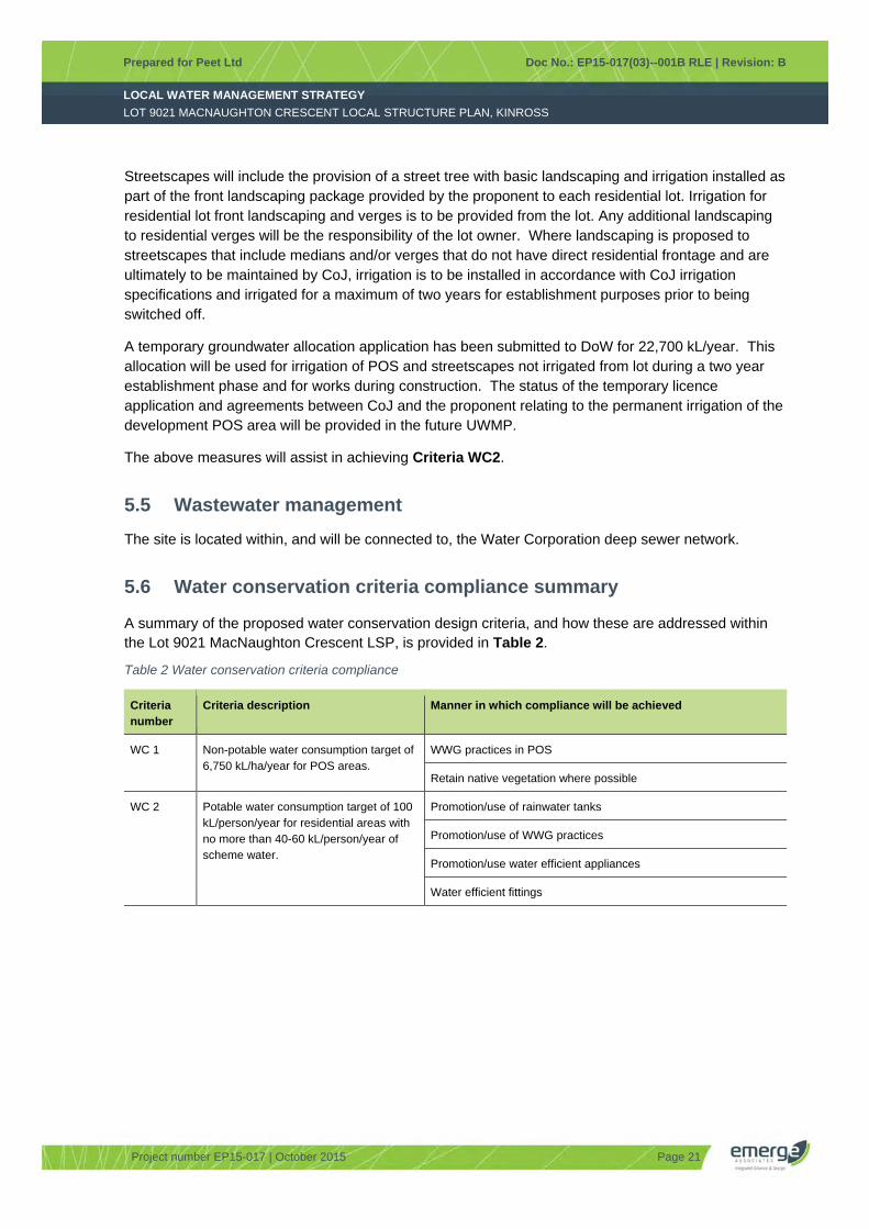
A summary of the proposed water conservation design criteria, and how these are addressed within the Lot 9021 MacNaughton Crescent LSP, is provided in Table 2.
Table 2 Water conservation criteria compliance
Criteria number
Criteria description Manner in which compliance will be achieved
WC 1 Non-potable water consumption target of 6,750 kL/ha/year for POS areas.
WWG practices in POS
Retain native vegetation where possible
WC 2 Potable water consumption target of 100 kL/person/year for residential areas with no more than 40-60 kL/person/year of scheme water.
Promotion/use of rainwater tanks
Promotion/use of WWG practices
Promotion/use water efficient appliances
Water efficient fittings

LOCAL WATER MANAGEMENT STRATEGY
Prepared for Peet Ltd Doc No.: EP15-017(03)--001B RLE | Revision: B
LOT 9021 MACNAUGHTON CRESCENT LOCAL STRUCTURE PLAN, KINROSS
Project number EP15-017 | October 2015 Page 22
6 Stormwater Management Strategy
The principle behind the stormwater management strategy for the Lot 9021 MacNaughton Crescent LSP is to infiltrate stormwater runoff as close to source as possible and to utilise existing infrastructure which has been planned and installed to cater for runoff from the site. The utilisation of various WSUD strategies within the development drainage system along with connection to the existing local drainage network will achieve the design criteria stated in Section 4.3. WSUD techniques utilised in the stormwater management strategy include:
Soakwells Sub-surface storage BRAs FSAs.
These measures are further discussed in the subsequent sections.
6.1 Stormwater management approach
The development drainage system has been designed to achieve the objectives and criteria stated in Section 4.3. Surface runoff modelling undertaken using XPSWMM has been used to inform the design of stormwater infrastructure as detailed below. Modelling assumptions are provided in Appendix D. The post-development catchments across the Lot 9021 MacNaughton Crescent LSP are shown in Figure 5.
6.1.1 Lot drainage
Lots are assumed to retain the 100 year ARI event on lot within soakwells, RWTs where they are installed, and pervious garden areas. Where RWTs are to be used for stormwater storage a low flow outlet will be required to ensure there is adequate capacity within the tank during a rainfall event.
It is the lot owner’s responsibility to ensure that adequate storage is provided for the 100 year ARI event runoff from lot. The retention of runoff on lot will assist in achieving Criteria SW1, SW5, SW7 and GW2.
6.1.2 Sub-surface storage
The 1 year 1 hour ARI event runoff from the road network within Catchment 1 will be retained in sub-surface storage (a storage volume of 20 m3 is required). There are a number of sub-surface storage products available (e.g. EcoAid) and the specific design and configuration of the sub-surface storage will be determined at detailed design and presented in the future UWMP.
The use of sub-surface storage will assist in achieving Criteria SW1, SW5, SW7 and GW2.
6.1.3 Bio-retention areas
The 1 year 1 hour ARI event runoff from the road network within Catchment 2 will be retained within a BRA located in POS. The BRA has a storage capacity of 10 m3, a maximum depth of 300 mm and 1:3 side slopes.

LOCAL WATER MANAGEMENT STRATEGY
Prepared for Peet Ltd Doc No.: EP15-017(03)--001B RLE | Revision: B
LOT 9021 MACNAUGHTON CRESCENT LOCAL STRUCTURE PLAN, KINROSS
Project number EP15-017 | October 2015 Page 23
Rainfall events greater than the 1 year 1 hour ARI event will be conveyed by weir structure or pipe to the adjacent FSA (detailed in Section 6.1.4). An indicative location and area for the BRA is provided in Figure 5.
The BRA will be underlain with a 300 mm layer of soil media suitable for nutrient removal. The soil media can be comprised of naturally found soils with a high PRI (>10) or an engineered media with appropriate specification (e.g. Eco media). The exact media to be used will be confirmed at UWMP stage.
The total size of the BRA is 5.3 % of the connected impervious area (road pavement and impervious verges).
The use and design of the BRA will assist in achieving Criteria SW1, SW3, SW5, SW6, SW7, GW1 and GW2.
6.1.4 Flood storage areas
A FSA will be utilised to retain up to the 5 year ARI event runoff from Catchment 2. The FSA has a storage capacity of 20 m3, a maximum depth of 500 mm and 1:6 side slopes. An indicative location and area for the FSA is provided within Figure 5.
The FSA will be designed to ensure a minimum 300 mm clearance is maintained between habitable floor levels and the 100 year ARI top water levels within the basin.
The use and design of FSAs will assist in achieving Criteria SW1, SW3, SW5, SW7 and GW2.
The number and configuration of sub-surface storage cells, BRAs and FSAs can be modified at detailed design stage provided the assumed storages detailed above are maintained. The Landscape Masterplan, provided in Appendix B, shows how the development is intended to be landscaped. Note that the BRA and FSA characteristics are nominal, and will need to be confirmed/revised following outcomes of any geotechnical investigation, the development of the detailed earthworks strategy and detailed civil designs.
6.1.5 Piped drainage network
The piped drainage network within the site will be sized to convey the 5 year ARI event runoff from the road network.
As detailed in Section 3.5.3, a connection to the existing drainage network has been provided to the site at the proposed main entry road (indicated as Discharge 1 in Figure 5). Flows from Catchment 1, above the 1 year 1 hour ARI event, will be conveyed to the downstream drainage network via the pipe network (for the 5 year ARI event) and overland flow within road pavements (up to the 100 year ARI event). The peak flow rate leaving the site at Discharge 1 in a 5 year ARI event is 0.03 m3/s which is within the maximum allowable capacity of the existing pipe infrastructure of 0.08 m3/s.
The use and design of the piped network will assist in achieving Criteria SW1 and SW4.

LOCAL WATER MANAGEMENT STRATEGY
Prepared for Peet Ltd Doc No.: EP15-017(03)--001B RLE | Revision: B
LOT 9021 MACNAUGHTON CRESCENT LOCAL STRUCTURE PLAN, KINROSS
Project number EP15-017 | October 2015 Page 24
6.2 Compliance summary
A summary of the proposed surface water design criteria and how these are addressed within the Lot 9021 MacNaughton Crescent LSP development is provided in Table 3.
Table 3 Surface water management criteria compliance
Criteria number
Criteria description Manner in which compliance will be achieved
SW1 Maintain the 5 year ARI event peak flow rate consistent with the capacity of the existing downstream network
Lots will retain the 100 year ARI event runoff from lot within soakwells, RWTs where implemented, and pervious garden areas
Runoff from roads will be retained in subsurface storage, a BRA and a FSA
SW2 Provide a flow path to convey the 100 year ARI event runoff to the downstream drainage network
The earthworks concept plan (provided in Appendix E) shows that the road network will be graded towards the adjacent existing roads, thus providing a flow path to the downstream drainage network
SW2 Maintain 300 mm clearance between finished floor levels and the 100 year ARI TWL within onsite storage areas (BRAs and FSAs).
A minimum 300 mm clearance between finished floor levels and the 100 year ARI TWL in the BRA and FSA will be maintained
SW3 Minor roads must remain passable in the 5 year ARI rainfall event.
The stormwater pipe network will be designed to convey the 5 year ARI rainfall event from the road network
SW4 Retain and treat the 1 year 1 hour ARI event as close to source as possible.
Lots will retain the 1 year 1 hour ARI event runoff from the lot within soakwells and pervious garden areas
The 1 year 1 hour ARI event runoff from roads will be retained in subsurface storage and a BRA
SW5 Treatment areas to be sized to at least 2% of the total connected impervious area.
The total size of the BRA is 5.3 % of the connected impervious area (road pavement, impervious verges and front of lots)
SW6 Utilise appropriate structural and non-structural measures to reduce nutrient loads.
Structural measures include soakwells, subsurface storage and a vegetated BRA
WWG practices
Maintenance of POS and drainage areas
Street sweeping
Education of residents
LOCAL WATER MANAGEMENT STRATEGY
Prepared for Peet Ltd Doc No.: EP15-017(03)--001B RLE | Revision: B
LOT 9021 MACNAUGHTON CRESCENT LOCAL STRUCTURE PLAN, KINROSS
Project number EP15-017 | October 2015 Page 25
7 Groundwater Management Strategy
The development drainage system has been designed to achieve the objectives and criteria stated in Section 4.4. The preliminary earthworks levels shown in Appendix E indicate that the proposed development will have more than 20 m separation to underlying groundwater, therefore groundwater management criteria concentrate on groundwater quality.
7.1 Groundwater quality management
The main objective of the management of groundwater quality is to maintain or improve the existing groundwater quality. This can be achieved by reducing the total nutrient load to groundwater from sources within the development and by improving the groundwater via treatment of surface runoff prior to infiltrating to groundwater.
The reduction of nutrient loads to groundwater will be achieved by the following measures:
Direct stormwater to a vegetated BRA. BRA will be underlain with a 300 mm layer of soil media suitable for nutrient removal. The soil
media can be comprised of naturally occurring soils with a high PRI (>10) or an engineered media with appropriate specification (e.g Eco media). The exact media to be used will be confirmed at UWMP stage.
Minimising fertiliser use to establish and maintain vegetation within POS areas and road verges. Utilising drought tolerant turf species that require minimal water and nutrients. Roll-on turf will be used within POS areas to prevent the high nutrient input requirement during
establishment of turf.
The above measures will improve the quality of the water prior to it infiltrating into the underlying groundwater, and will assist in achieving Criteria GW1 and Criteria GW2.
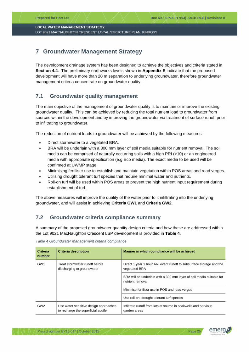
7.2 Groundwater criteria compliance summary
A summary of the proposed groundwater quantity design criteria and how these are addressed within the Lot 9021 MacNaughton Crescent LSP development is provided in Table 4.
Table 4 Groundwater management criteria compliance
Criteria number
Criteria description Manner in which compliance will be achieved
GW1 Treat stormwater runoff before discharging to groundwater
Direct 1 year 1 hour ARI event runoff to subsurface storage and the vegetated BRA
BRA will be underlain with a 300 mm layer of soil media suitable for nutrient removal
Minimise fertiliser use in POS and road verges
Use roll-on, drought tolerant turf species
GW2 Use water sensitive design approaches to recharge the superficial aquifer
Infiltrate runoff from lots at source in soakwells and pervious garden areas

LOCAL WATER MANAGEMENT STRATEGY
Prepared for Peet Ltd Doc No.: EP15-017(03)--001B RLE | Revision: B
LOT 9021 MACNAUGHTON CRESCENT LOCAL STRUCTURE PLAN, KINROSS
Project number EP15-017 | October 2015 Page 26
Criteria number
Criteria description Manner in which compliance will be achieved
Retain and infiltrate road reserve runoff in subsurface storage, BRA and FSA

LOCAL WATER MANAGEMENT STRATEGY
Prepared for Peet Ltd Doc No.: EP15-017(03)--001B RLE | Revision: B
LOT 9021 MACNAUGHTON CRESCENT LOCAL STRUCTURE PLAN, KINROSS
Project number EP15-017 | October 2015 Page 27
8 Matters to be addressed in the UWMP
While strategies have been provided within this LWMS that address planning for water management within the site, it is a logical progression that future subdivision designs and supportive UWMPs will clarify details not provided within the LWMS. The main areas that will require further clarification within future UWMPs include:
Detailed drainage design Implementation of water conservation strategies Non-structural water quality improvement measures Management and maintenance requirements Construction period management strategy Groundwater license status Subsurface infrastructure design Geotechnical report.
8.1 Detailed drainage design
While the Lot 9021 MacNaughton Crescent LSP drainage catchments have been defined based on the earthworks concept plan (presented in Appendix E), it is possible that these could undergo some change to accommodate stakeholder feedback prior to final subdivision design. It is also expected that the civil drainage designs will be progressed to a level that provides detailed cross-sections, sizes of storage areas, pipe sizes, inverts, etc. The ultimate aim of revising the hydrological model will be to confirm that the post-development runoff volumes are able to meet the performance criteria proposed in Section 4 of this LWMS. The design of the drainage system to date has been undertaken at an appropriate level for LSP and runoff-routing computer modelling of the stormwater drainage system will be reviewed once detailed drainage design has commenced for the area. The exact location and shape of the stormwater management infrastructure will still need to be specified and presented within the future UWMP.
The exception to the requirement to revise the surface runoff modelling is if the catchment details, sub-surface storage, BRA and FSA designs are consistent with the assumptions made in this LWMS. If this were the case it would be acceptable to provide design calculations for the concrete pipe network and detention/retention areas to demonstrate compliance with the LWMS.
8.2 Implementation of water conservation strategies
A number of potential measures to conserve water have been presented within this LWMS. These water conservation strategies will be incorporated into the design and the ongoing maintenance of the POS area. Landscape design measures that will be incorporated into the water conservation strategy will be further detailed within the future UWMP. The manner in which the proponent intends to promote water conservation measures discussed in this LWMS to future lot owners will also be discussed within the future UWMP.

LOCAL WATER MANAGEMENT STRATEGY
Prepared for Peet Ltd Doc No.: EP15-017(03)--001B RLE | Revision: B
LOT 9021 MACNAUGHTON CRESCENT LOCAL STRUCTURE PLAN, KINROSS
Project number EP15-017 | October 2015 Page 28
8.3 Non-structural water quality improvement measures
Guidance for the development and implementation of non-structural water quality improvement measures is provided within the Stormwater Management Manual for Western Australia (DoW 2007). Some measures will be more appropriately implemented at a local government level, such as street sweeping, however many can be implemented relatively easily within the design and maintenance of the subdivision and the POS area. The future UWMP will provide reference to measures such as public education (through measures such as signage that may be implemented to raise awareness).
8.4 Management and maintenance requirements
The measures implemented to address surface and groundwater quality, such as the use of subsurface storage and BRAs, will require ongoing maintenance. It is therefore expected that future UWMPs will provide detailed management and maintenance plans that will set out maintenance actions (e.g. gross pollutant removal), timing (e.g. how often it will occur), locations (e.g. exactly where it will occur) and responsibilities (e.g. who will be responsible for carrying out the actions). Given that approval from the CoJ and DoW will be sought for the proposed measures, it is anticipated that consultation with these agencies will be undertaken and referral to guiding policies and documents will be made.
8.5 Construction period management strategy
It is anticipated that the construction stage will require some management of various aspects (e.g. dust, surface runoff, noise, traffic etc.). The management measures undertaken for construction management will be addressed either in the future UWMP or a separate Construction Management Plan (CMP).
8.6 Groundwater license status
An application has been submitted for a temporary groundwater allocation for both irrigation and construction purposes, as discussed in Section 5.4. This licence will be used for establishment irrigation of POS and streetscapes, and dust suppression during construction. The current status of any groundwater licence application will be provided at UWMP stage.
The permanent irrigation of the development POS area will be provided by CoJ following upgrade works to the existing irrigation infrastructure and landscaping of the adjacent MacNaughton Park POS. Details of the works to be carried out and confirmation of the agreement to provide groundwater allocation for the development POS area will be provided in the future UWMP.
8.7 Subsurface infrastructure design
Numerous proprietary subsurface storage products are available for use within the context discussed in this LWMS. The selection and design of specific subsurface storage infrastructure will be detailed at UWMP stage. The management and maintenance requirements of such infrastructure will also be detailed at the subsequent UWMP stage.

LOCAL WATER MANAGEMENT STRATEGY
Prepared for Peet Ltd Doc No.: EP15-017(03)--001B RLE | Revision: B
LOT 9021 MACNAUGHTON CRESCENT LOCAL STRUCTURE PLAN, KINROSS
Project number EP15-017 | October 2015 Page 29
8.8 Geotechnical report
A geotechnical investigation of the site is required to inform subdivision design and confirm the underlying soil conditions across the site. The full geotechnical report will be provided and summarised in the future UWMP.

LOCAL WATER MANAGEMENT STRATEGY
Prepared for Peet Ltd Doc No.: EP15-017(03)--001B RLE | Revision: B
LOT 9021 MACNAUGHTON CRESCENT LOCAL STRUCTURE PLAN, KINROSS
Project number EP15-017 | October 2015 Page 30
9 Monitoring
9.1 Condition monitoring
It is proposed that the overall condition of the development will be monitored on a bi-annual basis. This monitoring will be implemented after the completion of the civil and landscaping works and will continue for a period of two years.
A visual assessment will be undertaken to monitor the overall condition of the development, with the aim to ascertain that the maintenance activities are achieving the overall management objectives for the development. The parameters that will be monitored include:
Gross pollutants Terrestrial weeds Irrigation Vegetation density Paths, benches, walkways and other infrastructure. The management and maintenance objectives will be detailed within the future UWMP.
It should be noted that site specific post-development groundwater monitoring is not proposed due to the significant (>25 m) depth to groundwater.
9.2 Reporting
A post-development monitoring report will be prepared on conclusion of the two year monitoring period, and will be provided to the CoJ. Interim results (spreadsheet) can be provided to CoJ on request during the monitoring program.

LOCAL WATER MANAGEMENT STRATEGY
Prepared for Peet Ltd Doc No.: EP15-017(03)--001B RLE | Revision: B
LOT 9021 MACNAUGHTON CRESCENT LOCAL STRUCTURE PLAN, KINROSS
Project number EP15-017 | October 2015 Page 31
10 Implementation
This LWMS is a key supportive document for the Lot 9021 MacNaughton Crescent LSP. The development of this LWMS has been undertaken with the intention of providing a structure within which subsequent development can occur consistent with an integrated water cycle management approach. It is also intended to provide overall guidance to the general stormwater management principles for the site and to guide the development of the future UWMP.
10.1 Roles and responsibility
This LWMS provides a framework that the developer can utilise to assist in establishing stormwater management methods that have been based upon site-specific investigations, are consistent with relevant State policies and have been endorsed by the CoJ. The responsibility for working within the framework established within the LWMS rests with the proponent, although it is anticipated that the future UWMP will be developed in consultation with the CoJ and DoW as these will be the ultimate approval agencies.
It will be the responsibility of the proponent to prepare detailed designs and the supportive UWMP. It is also the responsibility of the proponent to demonstrate that the proposed detailed civil designs and the supportive UWMP comply with the objectives and management approaches provided in this LWMS.
10.2 Funding
As the site constitutes a single landholding, the management strategies outlined in this LWMS will be borne solely by the proponent.
10.3 Recommendations
It is not anticipated that this LWMS will be reviewed, unless additional land parcels/lots are added to the Lot 9021 MacNaughton Crescent LSP prior to detailed design or the Lot 9021 MacNaughton Crescent LSP undergoes significant change post-lodgement. If additional areas are required to be covered by the LWMS it is most likely that an addendum to cover these areas could be prepared. If the Lot 9021 MacNaughton Crescent LSP is substantially modified this LWMS will need to be reviewed and the criteria reviewed to ensure that all are still appropriate.
The next stages of water management are anticipated to be detailed design. Detailed civil designs should be supported by a UWMP. The UWMP is largely an extension of the LWMS, as it should provide detail to the designs proposed within this LWMS, and will demonstrate compliance with the criteria proposed in Section 4.
LOCAL WATER MANAGEMENT STRATEGY
Prepared for Peet Ltd Doc No.: EP15-017(03)--001B RLE | Revision: B
LOT 9021 MACNAUGHTON CRESCENT LOCAL STRUCTURE PLAN, KINROSS
Project number EP15-017 | October 2015 Page 32
11 References
11.1 General references
Australian Bureau of Statistics (ABS) 2013a, 4130.0 - Housing Occupancy and Costs 2011-12, Australian Bureau of Statistics, Canberra.
Australian Bureau of Statistics (ABS) 2013b, 4602.0.55.003 - Environmental Issues: Water Use and Conservation, March 2013, Australian Bureau of Statistics, Canberra.
Australian and New Zealand Environment and Conservation Council (ANZECC) 2000, Australia and New Zealand Guidelines for Fresh and Marine Water Quality, National Water Quality Management Strategy Australian and New Zealand Environment and Conservation Council.
City of Joondalup (CoJ) 1998, Development Design Specification JD5: Stormwater Drainage Design.
City of Joondalup (CoJ) 2007, Policy 6-3: Stormwater Drainage, City of Joondalup, Joondalup.
City of Joondalup (CoJ) 2011, City of Joondalup City Water Plan 2012-2015, City of Joondalup, Joondalup.
City of Joondalup (CoJ) 2012, Stormwater Management Policy, City of Joondalup, Joondalup.
City of Joondalup (CoJ) 2014, Local Planning Strategy, City of Joondalup, Joondalup.
Department of Water (DoW) 2007, Stormwater Management Manual for Western Australia, Department of Water, Perth.
Department of Water (DoW) 2009, Decision Process for Stormwater Management in Western Australia, Department of Water, Perth.
Emerge Associates 2015, Lot 9021 MacNaughton Cresecent Local Structure Plan, Kinross Environmental Assessment and Management Strategy unpublished report prepared by Emerge Associates, Subiaco.
Engineers Australia 1987, Australian Rainfall and Runoff, National Committee for Water Engineering, Canberra.
Engineers Australia 2006, Australian Runoff Quality: A guide to Water Sensitive Urban Design, National Committee for Water Engineering, Engineers Australia, Canberra.
Environmental Protection Authority (EPA) 2008, Guidance Statement No. 33: Environmental Guidance for Planning and Development, Environmental Protection Authority, Perth.
Government of WA 2003a, State Water Strategy, Perth.
Government of WA 2003b, A State Water Strategy for Western Australia, Government of Western Australia, Perth.
Government of WA 2009, Gnangara Sustainability Strategy, Perth.
Gozzard, J. R. 1982, Yanchep Sheet 2034 IV, Perth Metropolitan Region, Geological Survey of Western Australia, Perth.
Western Australian Planning Commission (WAPC) 2006, State Planning Policy 2.9: Water Resources, Gazetted in December 2006. Western Australian Planning Commission, Perth.
Western Australian Planning Commission (WAPC) 2007, Liveable Neighbourhoods (Edition 4), Western Australian Planning Commission and Department for Planning and Infrastructure, Perth.

LOCAL WATER MANAGEMENT STRATEGY
Prepared for Peet Ltd Doc No.: EP15-017(03)--001B RLE | Revision: B
LOT 9021 MACNAUGHTON CRESCENT LOCAL STRUCTURE PLAN, KINROSS
Project number EP15-017 | October 2015 Page 33
Western Australian Planning Commission (WAPC) 2008, Better Urban Water Management, Western Australian Planning Commission, Perth.
Western Australian Planning Commission (WAPC) 2009, Planning Bulletin No. 64 Acid Sulfate Soils, Western Australian Planning Commission, January 2009, Perth.
Water Corporation (WC) 2003, Domestic Water Use Study in Perth, Western Australia 1998-2001, Water Corporation, Perth.
Water Corporation (WC) 2011, AltWaterSupply_Water_Use_Model.xls, Water Corporation, Perth.
11.2 Online references
Bureau of Meteorology 2015, Climate Averages, viewed 29 April 2015, <http://www.bom.gov.au/climate/averages/tables/cw_009225.shtml>.
City of Joondalup (CoJ) 2015, Intramaps, viewed 29th April 2015, <http://maps.joondalup.wa.gov.au/intramaps80/ >.
Department of Environment Regulation (DER) 2015, Contaminated Sites Database, viewed 29 April 2015, <https://secure.dec.wa.gov.au/idelve/css/>.
Department of Water (DoW) 2015a, Perth Groundwater Atlas, viewed 28th April 2015, <http://portal.water.wa.gov.au/portal/page/portal/MapsDataAtlases/PerthGroundwaterAtlas>.
Department of Water (DoW) 2015b, Water Register, 28th April 2015, <http://www.water.wa.gov.au/Tools/Maps+and+atlases/Water+Register/default.aspx#1>.
Landgate 2015, WA Atlas, viewed 29 April 2015, <https://www2.landgate.wa.gov.au/bmvf/app/waatlas/>.
Western Australian Planning Commission (WAPC) 2015, Metropolitan Region Scheme Mapping, viewed 29th April 2015, < http://www.planning.wa.gov.au/dop_pub_pdf/mrs7.pdf >.

LOCAL WATER MANAGEMENT STRATEGY
Prepared for Peet Ltd Doc No.: EP15-017(03)--001B RLE | Revision: B
LOT 9021 MACNAUGHTON CRESCENT LOCAL STRUCTURE PLAN, KINROSS
Project number EP15-017 | October 2015
FIGURES
Figure 1: Site location
Figure 2: Site boundary
Figure 3: Topography
Figure 4: Geological mapping
Figure 5: Stormwater management plan

LOCAL WATER MANAGEMENT STRATEGY
Prepared for Peet Ltd Doc No.: EP15-017(03)--001B RLE | Revision: B
LOT 9021 MACNAUGHTON CRESCENT LOCAL STRUCTURE PLAN, KINROSS
Project number EP15-017 | October 2015
This page has been left blank intentionally.
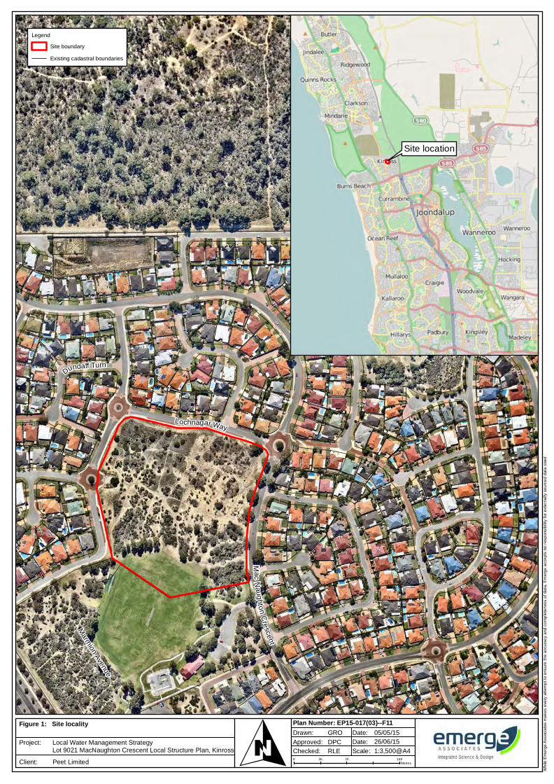
Wh
ile E
me
rge
Ass
ocia
tes
ma
kes
eve
ry a
tte
mp
t to
ens
ure
th
e a
ccu
racy
an
d c
om
ple
ten
ess
of
data
, E
me
rge
acc
ep
ts n
o r
esp
ons
ibili
ty f
or
ext
ern
ally
so
urc
ed
dat
a u
sed
Aerial photograph: Nearmaps
0 70 14035Metres
1:3,500@A4Approved:
RLE
GRO
DPC
05/05/1526/06/15
Plan Number: EP15-017(03)--F11Drawn: Date:
Date:
Scale: Checked:OFigure 1:
Project:
Client:
Site locality
Local Water Management StrategyLot 9021 MacNaughton Crescent Local Structure Plan, Kinross
Peet Limited
Legend
Site boundary
Existing cadastral boundaries
Site location
Marm
ion Avenue
Lochnagar Way
Mac
Naug
hton
Cre
scent
Dundaff Turn
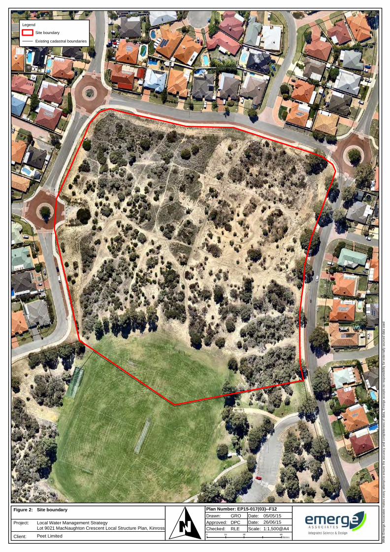
Wh
ile E
me
rge
Ass
ocia
tes
ma
kes
eve
ry a
tte
mp
t to
ens
ure
th
e a
ccu
racy
an
d c
om
ple
ten
ess
of
data
, E
me
rge
acc
ep
ts n
o r
esp
ons
ibili
ty f
or
ext
ern
ally
so
urc
ed
dat
a u
sed
Aerial photograph: Nearmaps
0 30 6015Metres
1:1,500@A4Approved:
RLE
GRO
DPC
05/05/1526/06/15
Plan Number: EP15-017(03)--F12Drawn: Date:
Date:
Scale: Checked:OFigure 2:
Project:
Client:
Site boundary
Local Water Management StrategyLot 9021 MacNaughton Crescent Local Structure Plan, Kinross
Peet Limited
Legend
Site boundary
Existing cadastral boundaries
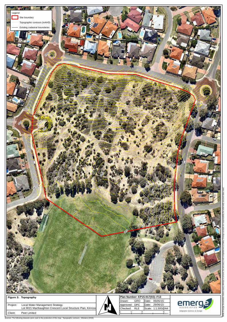
Wh
ile E
me
rge
Ass
ocia
tes
ma
kes
eve
ry a
tte
mp
t to
ens
ure
th
e a
ccu
racy
an
d c
om
ple
ten
ess
of
data
, E
me
rge
acc
ep
ts n
o r
esp
ons
ibili
ty f
or
ext
ern
ally
so
urc
ed
dat
a u
sed
Aerial photograph: Nearmaps
Sources: The following datasets were used in the production of this map: Topographic contours - Whelans (2015)
0 30 6015Metres
1:1,500@A4Approved:
RLE
GRO
DPC
05/05/1526/06/15
Plan Number: EP15-017(03)--F13Drawn: Date:
Date:
Scale: Checked:OFigure 3:
Project:
Client:
Topography
Local Water Management StrategyLot 9021 MacNaughton Crescent Local Structure Plan, Kinross
Peet Limited
27.0
28.0
29.0
30.0
31.0
32.0
33.0
33.0
34.0
34.0 35
.0
35.0
36.0
36.0
Legend
Site boundary
Topographic contours (mAHD)
Existing cadastral boundaries
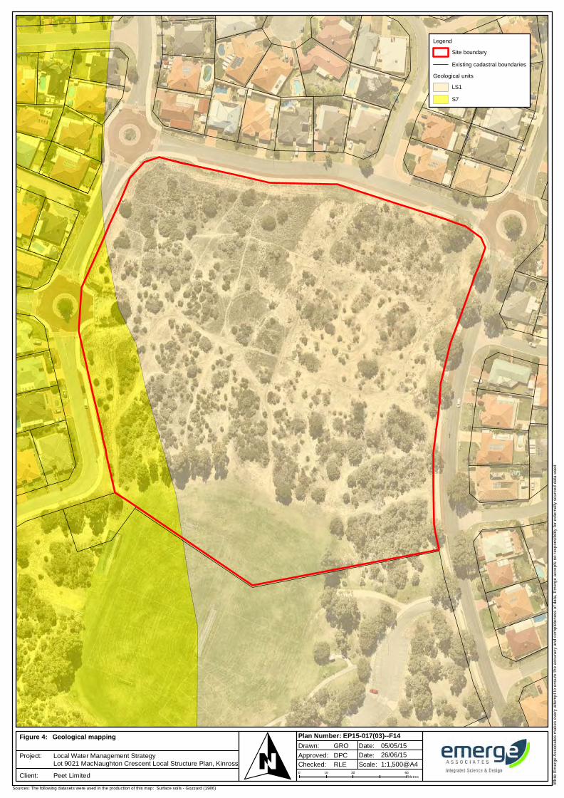
Wh
ile E
me
rge
Ass
ocia
tes
ma
kes
eve
ry a
tte
mp
t to
ens
ure
th
e a
ccu
racy
an
d c
om
ple
ten
ess
of
data
, E
me
rge
acc
ep
ts n
o r
esp
ons
ibili
ty f
or
ext
ern
ally
so
urc
ed
dat
a u
sed
Aerial photograph: Nearmaps
Sources: The following datasets were used in the production of this map: Surface soils - Gozzard (1986)
0 30 6015Metres
1:1,500@A4Approved:
RLE
GRO
DPC
05/05/1526/06/15
Plan Number: EP15-017(03)--F14Drawn: Date:
Date:
Scale: Checked:OFigure 4:
Project:
Client:
Geological mapping
Local Water Management StrategyLot 9021 MacNaughton Crescent Local Structure Plan, Kinross
Peet Limited
Legend
Site boundary
Existing cadastral boundaries
Geological units
LS1
S7

Wh
ile E
me
rge
Ass
ocia
tes
ma
kes
eve
ry a
tte
mp
t to
ens
ure
th
e a
ccu
racy
an
d c
om
ple
ten
ess
of
data
, E
me
rge
acc
ep
ts n
o r
esp
ons
ibili
ty f
or
ext
ern
ally
so
urc
ed
dat
a u
sed
0 40 8020Metres
1:2,000@A4Approved:
RLE
SMF
DPC
27/05/1526/06/15
Plan Number: EP15-017(03)--F16Drawn: Date:
Date:
Scale: Checked:OFigure 5:
Project:
Client:
Stormwater management plan
Local Water Management StrategyLot 9021 MacNaughton Crescent Local Structure Plan
Peet Limited
Legend
Site boundary
LSP
Post-development catchments
100 year ARI flow direction
Bio-retention area
Flood storage area
Subsurface storage
Ct 1
Ct 2
1 year 1 hour ARIArea (m2) = 44Side slope = 1 in 3Depth (m) = 0.3Volume (m3) = 10
Bio-retention 2
POS
5 year 6 hours ARIArea (m2) = 82Side slope = 1 in 6Depth (m) = 0.5Volume (m3) = 20
FSA 2 (5 year ARI inundation)
5 year ARI pipeflow = 0.03 m3/s100 year ARI pipe/overland flow = 0.03 m3/s
100 year ARI overland flow = 0.01 m3/s
Discharge 1
Discharge 2
1 year 1 hour ARIsubsurface storage = 20 m3

LOCAL WATER MANAGEMENT STRATEGY
Prepared for Peet Ltd Doc No.: EP15-017(03)--001B RLE | Revision: B
LOT 9021 MACNAUGHTON CRESCENT LOCAL STRUCTURE PLAN, KINROSS
Project number EP15-017 | October 2015
This page has been left blank intentionally.

LOCAL WATER MANAGEMENT STRATEGY
Prepared for Peet Ltd Doc No.: EP15-017(03)--001B RLE | Revision: B
LOT 9021 MACNAUGHTON CRESCENT LOCAL STRUCTURE PLAN, KINROSS
Project number EP15-017 | October 2015
APPENDIX A LOCAL STRUCTURE PLAN

LOCAL WATER MANAGEMENT STRATEGY
Prepared for Peet Ltd Doc No.: EP15-017(03)--001B RLE | Revision: B
LOT 9021 MACNAUGHTON CRESCENT LOCAL STRUCTURE PLAN, KINROSS
Project number EP15-017 | October 2015
This page has been left blank intentionally.
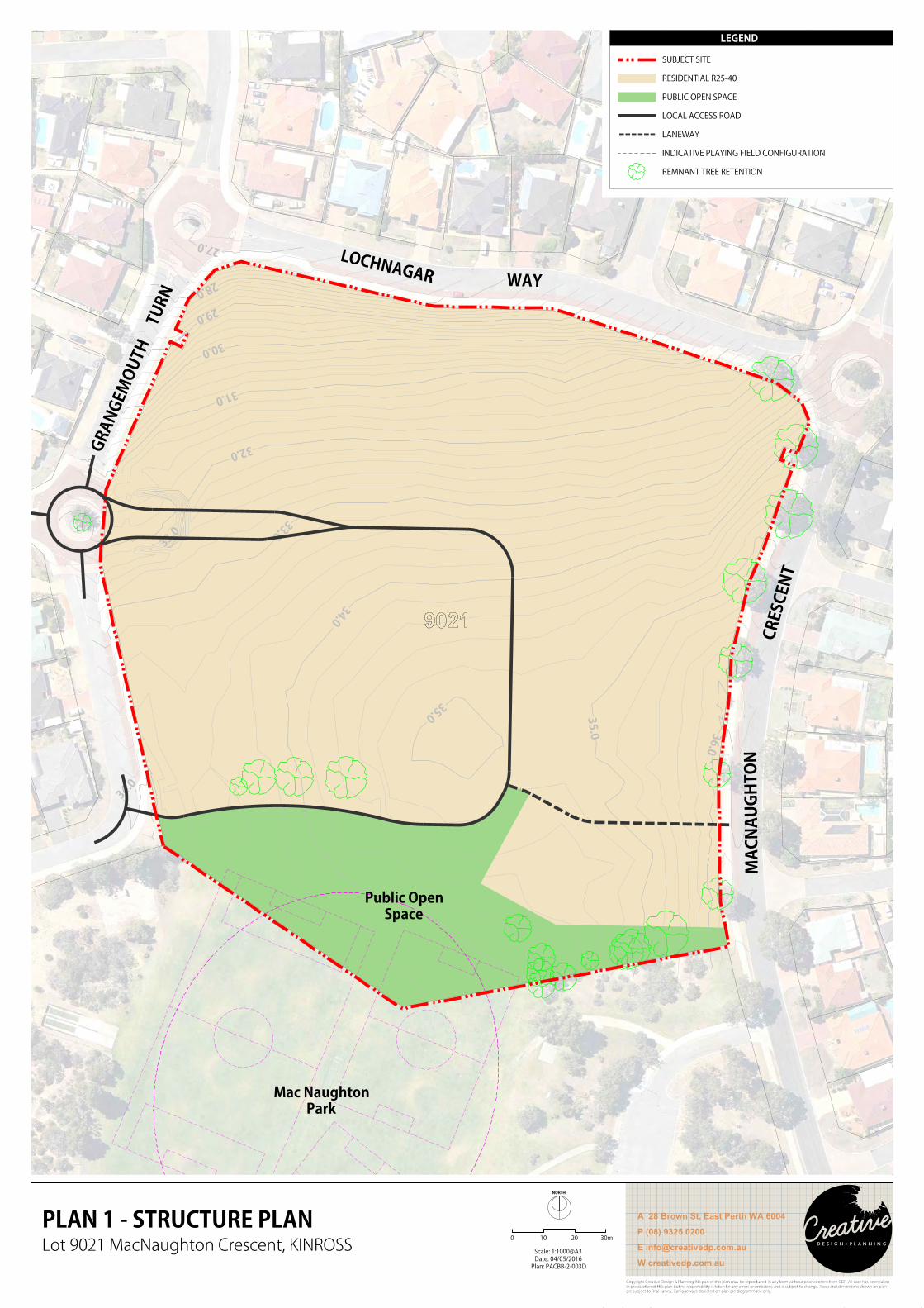
27.0
28.0
29.0
30.0
31.0
32.0
33.0
33.0
34.0
34.0
35.0
35.0
36.0
Space
Public Open
Park
Mac Naughton
0 10 20
NORTH
30m
Plan: PACBB-2-003D
Date: 04/05/2016
Scale: 1:1000@A3
GR
AN
GE
MO
UTH T
UR
N
MA
CN
AU
GH
TO
NCRESCEN
T
LOCHNAGAR WAY
9021
PLAN 1 - STRUCTURE PLANLot 9021 MacNaughton Crescent, KINROSS
W creativedp.com.au
P (08) 9325 0200
A 28 Brown St, East Perth WA 6004
are subject to final survey. Carriageways depicted on plan are diagrammatic only.
in preparation of this plan but no responsibility is taken for any errors or omissions and is subject to change. Areas and dimensions shown on plan
Copyright Creative Design & Planning. No part of this plan may be reproduced in any form without prior consent from CDP. All care has been taken
LEGEND
REMNANT TREE RETENTION
INDICATIVE PLAYING FIELD CONFIGURATION
LANEWAY
LOCAL ACCESS ROAD
PUBLIC OPEN SPACE
RESIDENTIAL R25-40
SUBJECT SITE
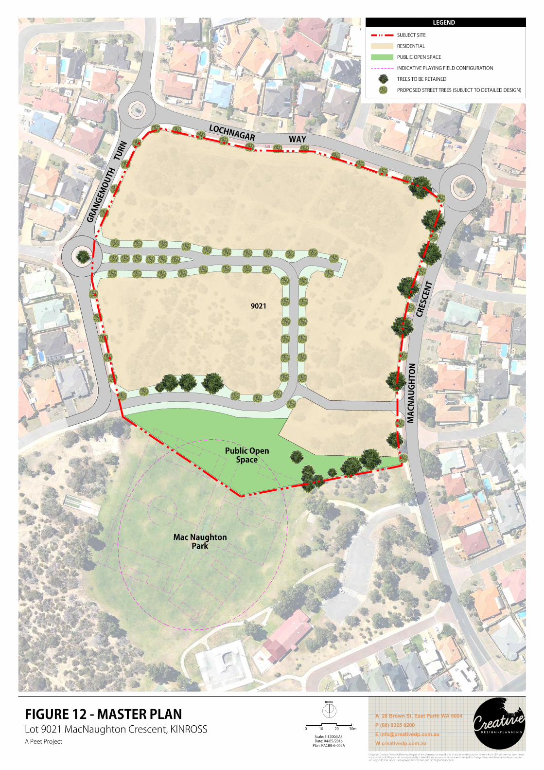
Park
Mac Naughton
Space
Public Open
0 10 20
NORTH
30m
GR
AN
GE
MO
UTH T
UR
N
MA
CN
AU
GH
TO
NCRESCEN
T
LOCHNAGAR WAY
9021
Lot 9021 MacNaughton Crescent, KINROSS
A Peet ProjectPlan: PACBB-6-002A
Date: 04/05/2016
Scale: 1:1200@A3
FIGURE 12 - MASTER PLAN
W creativedp.com.au
P (08) 9325 0200
A 28 Brown St, East Perth WA 6004
are subject to final survey. Carriageways depicted on plan are diagrammatic only.
in preparation of this plan but no responsibility is taken for any errors or omissions and is subject to change. Areas and dimensions shown on plan
Copyright Creative Design & Planning. No part of this plan may be reproduced in any form without prior consent from CDP. All care has been taken
LEGEND
PROPOSED STREET TREES (SUBJECT TO DETAILED DESIGN)
TREES TO BE RETAINED
INDICATIVE PLAYING FIELD CONFIGURATION
PUBLIC OPEN SPACE
RESIDENTIAL
SUBJECT SITE

LOCAL WATER MANAGEMENT STRATEGY
Prepared for Peet Ltd Doc No.: EP15-017(03)--001B RLE | Revision: B
LOT 9021 MACNAUGHTON CRESCENT LOCAL STRUCTURE PLAN, KINROSS
Project number EP15-017 | October 2015
APPENDIX B LANDSCAPE PLANS

LOCAL WATER MANAGEMENT STRATEGY
Prepared for Peet Ltd Doc No.: EP15-017(03)--001B RLE | Revision: B
LOT 9021 MACNAUGHTON CRESCENT LOCAL STRUCTURE PLAN, KINROSS
Project number EP15-017 | October 2015
This page has been left blank intentionally.
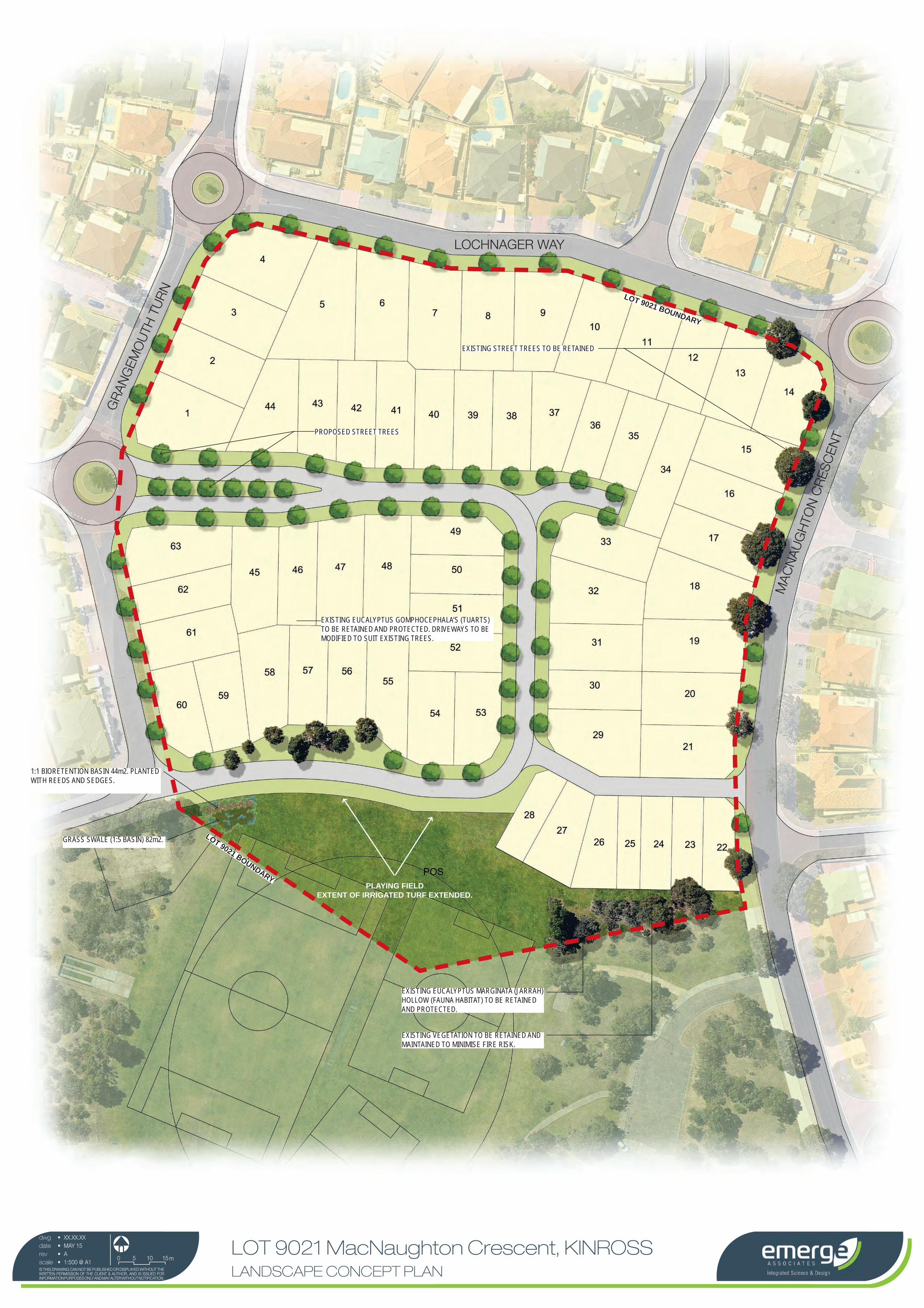
LOCHNAGER WAY
GR
ANG
EMO
UTH
TU
RN
MA
CN
AU
GH
TON
CR
ESC
ENT
LOT 9021 MacNaughton Crescent, KINROSS LANDSCAPE CONCEPT PLAN
dwgdaterevscale
XX.XX.XXMAY 15A1:500 @ A1
© THIS DRAWING CAN NOT BE PUBLISHED OR DISPLAYED WITHOUT THE WRITTEN PERMISSION OF THE CLIENT & AUTHOR, AND IS ISSUED FOR INFORMATION PURPOSES ONLY AND MAY ALTER WITHOUT NOTIFICATION.
••••
n0 5 10 15 m
PROPOSED STREET TREES
PLAYING FIELD EXTENT OF IRRIGATED TURF EXTENDED.
EXISTING EUCALYPTUS GOMPHOCEPHALA’S (TUARTS) TO BE RETAINED AND PROTECTED. DRIVEWAYS TO BE MODIFIED TO SUIT EXISTING TREES.
EXISTING EUCALYPTUS MARGINATA (JARRAH) HOLLOW (FAUNA HABITAT) TO BE RETAINED AND PROTECTED.
LOT 9021 BOUNDARY
EXISTING VEGETATION TO BE RETAINED AND MAINTAINED TO MINIMISE FIRE RISK.
EXISTING STREET TREES TO BE RETAINED
LOT 9021 BOUNDARY
1:1 BIORETENTION BASIN 44m2. PLANTED WITH REEDS AND SEDGES.
GRASS SWALE (1:5 BASIN) 82m2.
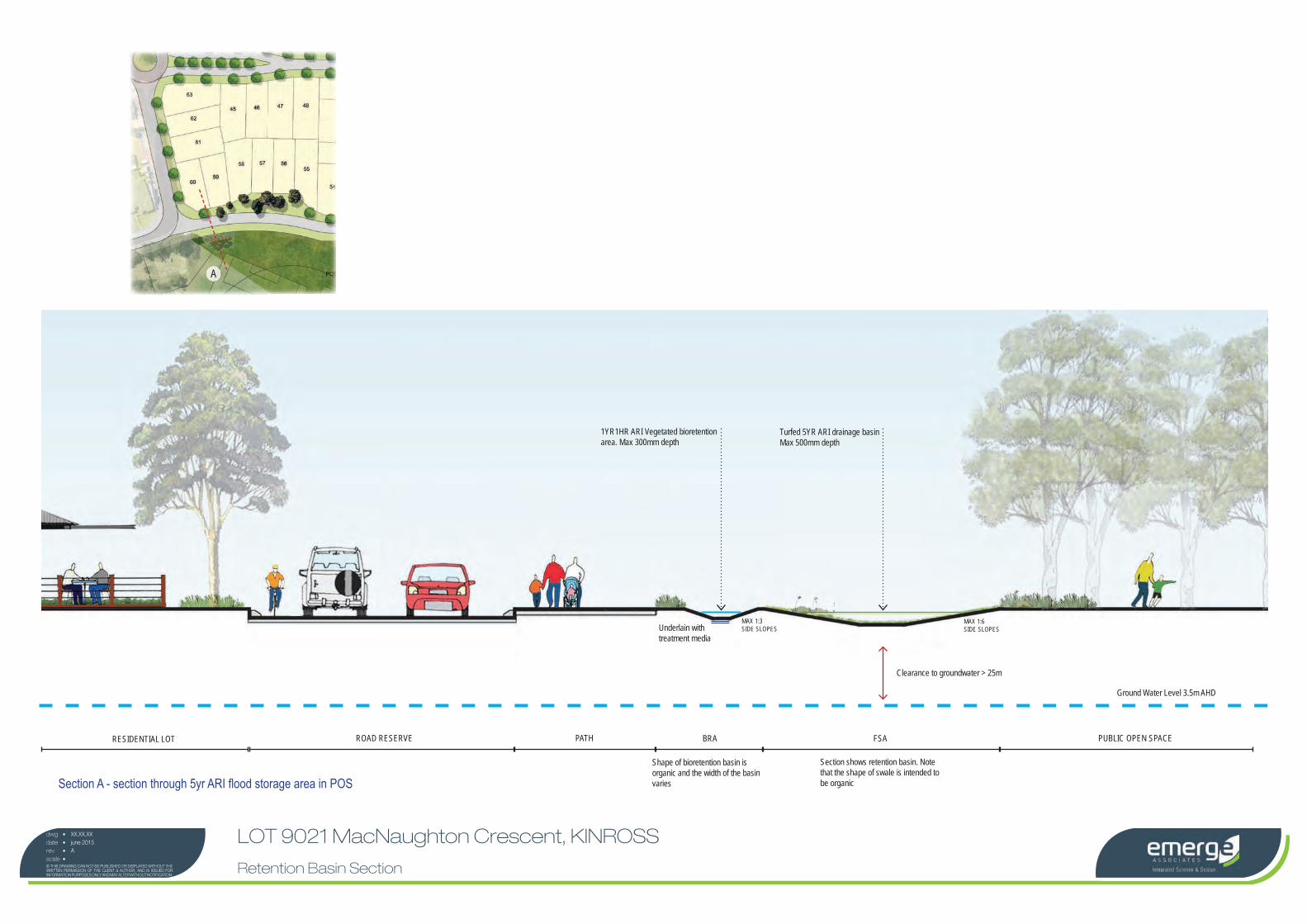
RESIDENTIAL LOT ROAD RESERVE PATH BRA PUBLIC OPEN SPACE
Shape of bioretention basin is organic and the width of the basin varies
FSA
Section shows retention basin. Note that the shape of swale is intended to be organic
MAX 1:3SIDE SLOPES
MAX 1:6SIDE SLOPES
Clearance to groundwater > 25m
Ground Water Level 3.5m AHD
Turfed 5YR ARI drainage basin Max 500mm depth
1YR1HR ARI Vegetated bioretention area. Max 300mm depth
Underlain with treatment media
LOT 9021 MacNaughton Crescent, KINROSS
Retention Basin Section
dwgdaterevscale
XX.XX.XXjune 2015A
© THIS DRAWING CAN NOT BE PUBLISHED OR DISPLAYED WITHOUT THE WRITTEN PERMISSION OF THE CLIENT & AUTHOR, AND IS ISSUED FOR INFORMATION PURPOSES ONLY AND MAY ALTER WITHOUT NOTIFICATION.
••••
A
Section A - section through 5yr ARI fl ood storage area in POS

LOCAL WATER MANAGEMENT STRATEGY
Prepared for Peet Ltd Doc No.: EP15-017(03)--001B RLE | Revision: B
LOT 9021 MACNAUGHTON CRESCENT LOCAL STRUCTURE PLAN, KINROSS
Project number EP15-017 | October 2015
APPENDIX C EXISTING DRAINAGE DESIGNS

LOCAL WATER MANAGEMENT STRATEGY
Prepared for Peet Ltd Doc No.: EP15-017(03)--001B RLE | Revision: B
LOT 9021 MACNAUGHTON CRESCENT LOCAL STRUCTURE PLAN, KINROSS
Project number EP15-017 | October 2015
This page has been left blank intentionally.
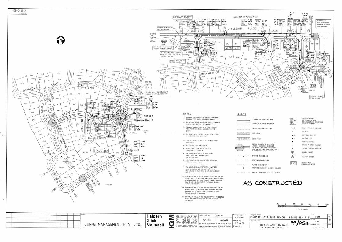
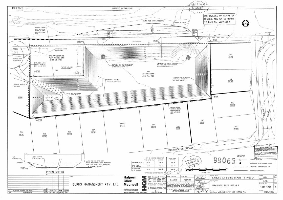
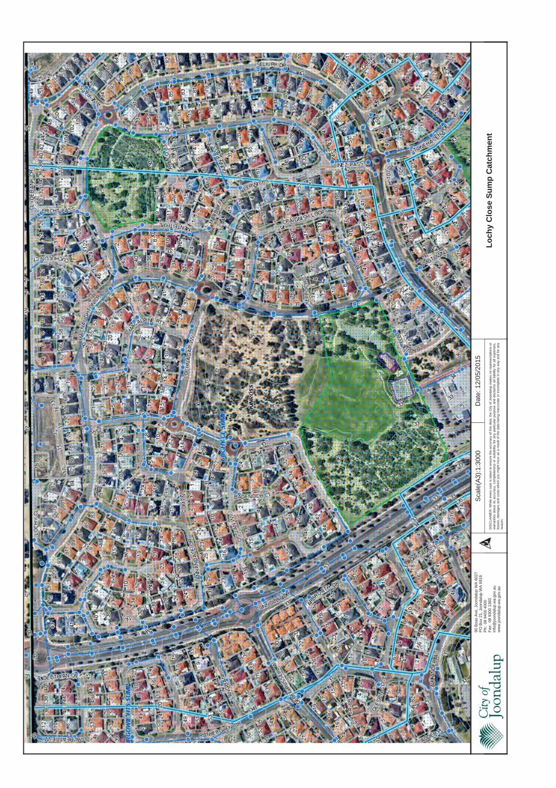
Sca
le(A
3):1
:300
0D
ate:
12/0
5/20
15
Lo
chy
Clo
se S
um
p C
atch
men
tD
ISC
LAIM
ER
:W
hile
ever
yca
reis
take
nto
ensu
reth
eac
cura
cyof
this
data
,th
eC
ityof
Joon
dalu
pm
akes
nore
pres
enta
tions
orw
arra
ntie
sab
out
itsac
cura
cy,
com
plet
enes
sor
suita
bilit
yfo
ran
ypa
rtic
ular
purp
ose
and
disc
laim
sal
llia
bilit
yfo
ral
lex
pens
es,
loss
es,
dam
ages
and
cost
sw
hich
you
mig
htin
cur
asa
resu
ltof
the
data
bein
gin
accu
rate
orin
com
plet
ein
any
way
and
for
any
reas
on.
90 B
oas
Ave
, Joo
ndal
up W
A 6
027
PO
Box
21,
Joo
ndal
up W
A 6
919
Ph:
08
9400
400
0F
ax:
08 9
300
1383
info
@jo
onda
lup.
wa.
gov.
auw
ww
.joon
dalu
p.w
a.go
v.au
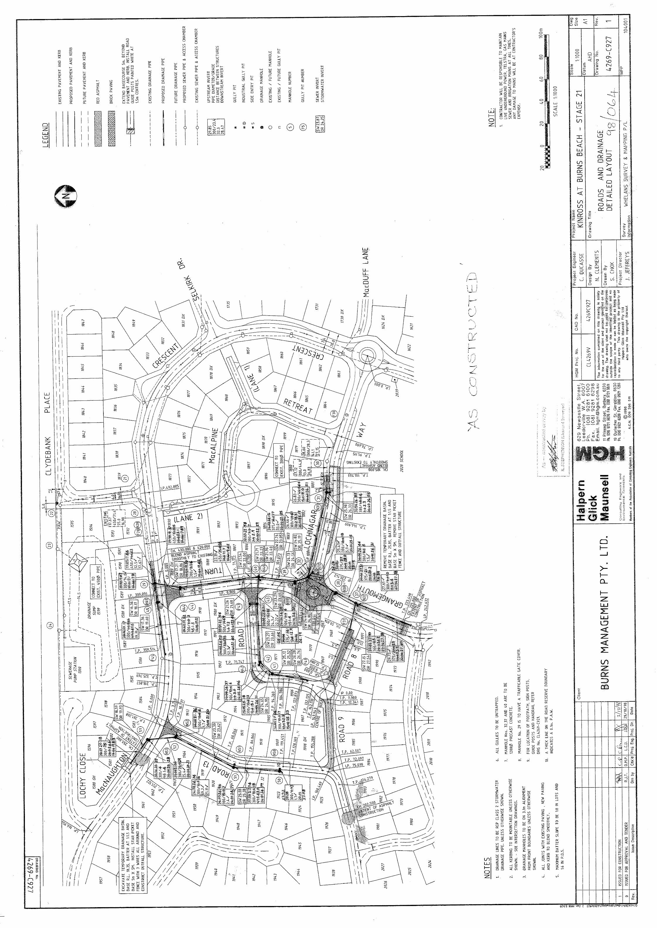

LOCAL WATER MANAGEMENT STRATEGY
Prepared for Peet Ltd Doc No.: EP15-017(03)--001B RLE | Revision: B
LOT 9021 MACNAUGHTON CRESCENT LOCAL STRUCTURE PLAN, KINROSS
Project number EP15-017 | October 2015
APPENDIX D MODELLING ASSUMPTIONS

LOCAL WATER MANAGEMENT STRATEGY
Prepared for Peet Ltd Doc No.: EP15-017(03)--001B RLE | Revision: B
LOT 9021 MACNAUGHTON CRESCENT LOCAL STRUCTURE PLAN, KINROSS
Project number EP15-017 | October 2015
This page has been left blank intentionally.

Project number EP15-017 | October 2015 Page 1
MODELLING ASSUMPTIONS LOT 9021 MACNAUGHTON CRESCENT, KINROSS LWMS Project Number EP15-017
Prepared for Peet Ltd October 2015

Project number EP15-017 | October 2015 Page i
Prepared for Peet Ltd Doc No.: EP15-017(03)--005A AP | Revision: A
MODELLING ASSUMPTIONS
LOT 9021 MACNAUGHTON CRESCENT, KINROSS LWMS
Document Control
DOC NAME LOT 9021 MACNAUGHTON CRESCENT, KINROSS LWMS MODELLING ASSUMPTIONS
DOC NO. EP15-017(03)--005 AP
REVISION DATE AUTHOR REVIEWER
1 June 2015 Amila Prasad AP Dave Coremans DPC
Issued as an Appendix to the LWMS
A October 2015 Amila Prasad AP Dave Coremans DPC
Issued as an Appendix to the LWMS
© 2015 Emerge Associates All Rights Reserved. Copyright in the whole and every part of this document belongs to Emerge Associates and may not be used, sold, transferred, copied or reproduced in whole or in part in any manner or form or in or on any media to any person without the prior written consent of Emerge Associates.

MODELLING ASSUMPTIONS
Prepared for Peet Ltd Doc No.: EP15-017(03)--005A AP | Revision: A
LOT 9021 MACNAUGHTON CRESCENT, KINROSS LWMS
Project number EP15-017 | October 2015 Page 1
1 Modelling Assumptions
XPSWMM hydrologic and hydraulic modelling software was used in order to calculate the surface water runoff volumes and peak flow rates from the Lot 9021 MacNaughton Crescent, Kinross Local Structure Plan (LSP) area (referred to as ‘the site’).
The hydrologic component of the software uses the Laurenson non-linear runoff-routing method to simulate runoff from design storm events. Key assumptions regarding the hydrologic model include:
Runoff is proportional to slope, area, infiltration and percentage imperviousness of a catchment. Sub-catchment areas and slopes are determined from and bulk earthworks plans supplied by
the project team. Infiltration rates and percentage imperviousness is based on experience with model preparation
for similar soil conditions.
Runoff from each sub-catchment is routed through the catchment using the hydraulic component of XPSWMM. Assumptions associated with the hydraulic component of the model include:
Virtual links (i.e. purely for model construction, not equivalent to flow paths onsite) between nodes within a sub-catchment are given the length of 10 m and slope of 5% to minimise the lag time of conveying the water from a sub-catchment node to a ‘storage’ node, a ‘dummy intermediate’ node or a conduit/link.
Links between sub-catchment storages act as conveyance channels (e.g. sheet flow within roads in 100 year Average Recurrence Interval (ARI) event). These links are given lengths and slopes to represent site conditions and actual pathway lengths between catchments.
Virtual links are designed with width of 5 m, roughness of 0.014 (Manning’s ‘n’) and are trapezoidal in shape. This allows for easy conveyance and/or represents concrete pipes/road surfaces.
No more than 5% of volume has been allowed to be ponded within 1 year 1 hour ARI storage nodes for events greater than the 1 year 1 hour ARI event.
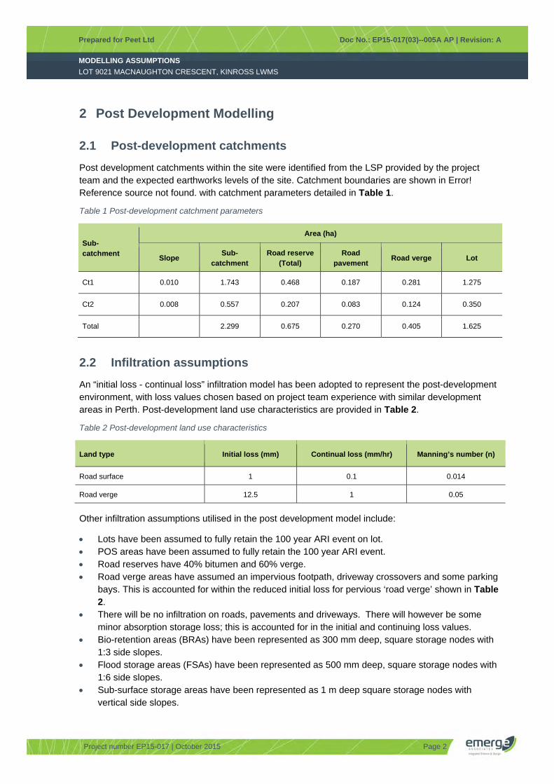
MODELLING ASSUMPTIONS
Prepared for Peet Ltd Doc No.: EP15-017(03)--005A AP | Revision: A
LOT 9021 MACNAUGHTON CRESCENT, KINROSS LWMS
Project number EP15-017 | October 2015 Page 2
2 Post Development Modelling
2.1 Post-development catchments
Post development catchments within the site were identified from the LSP provided by the project team and the expected earthworks levels of the site. Catchment boundaries are shown in Error! Reference source not found. with catchment parameters detailed in Table 1.
Table 1 Post-development catchment parameters
Sub-catchment
Area (ha)
Slope Sub-
catchment Road reserve
(Total) Road
pavement Road verge Lot
Ct1 0.010 1.743 0.468 0.187 0.281 1.275
Ct2 0.008 0.557 0.207 0.083 0.124 0.350
Total 2.299 0.675 0.270 0.405 1.625
2.2 Infiltration assumptions
An “initial loss - continual loss” infiltration model has been adopted to represent the post-development environment, with loss values chosen based on project team experience with similar development areas in Perth. Post-development land use characteristics are provided in Table 2.
Table 2 Post-development land use characteristics
Land type Initial loss (mm) Continual loss (mm/hr) Manning’s number (n)
Road surface 1 0.1 0.014
Road verge 12.5 1 0.05
Other infiltration assumptions utilised in the post development model include:
Lots have been assumed to fully retain the 100 year ARI event on lot. POS areas have been assumed to fully retain the 100 year ARI event. Road reserves have 40% bitumen and 60% verge. Road verge areas have assumed an impervious footpath, driveway crossovers and some parking
bays. This is accounted for within the reduced initial loss for pervious ‘road verge’ shown in Table 2.
There will be no infiltration on roads, pavements and driveways. There will however be some minor absorption storage loss; this is accounted for in the initial and continuing loss values.
Bio-retention areas (BRAs) have been represented as 300 mm deep, square storage nodes with 1:3 side slopes.
Flood storage areas (FSAs) have been represented as 500 mm deep, square storage nodes with 1:6 side slopes.
Sub-surface storage areas have been represented as 1 m deep square storage nodes with vertical side slopes.
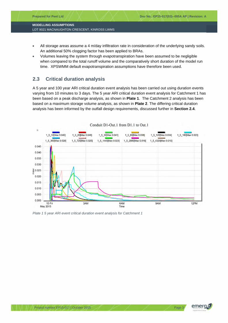
MODELLING ASSUMPTIONS
Prepared for Peet Ltd Doc No.: EP15-017(03)--005A AP | Revision: A
LOT 9021 MACNAUGHTON CRESCENT, KINROSS LWMS
Project number EP15-017 | October 2015 Page 3
All storage areas assume a 4 m/day infiltration rate in consideration of the underlying sandy soils. An additional 50% clogging factor has been applied to BRAs.
Volumes leaving the system through evapotranspiration have been assumed to be negligible when compared to the total runoff volume and the comparatively short duration of the model run time. XPSWMM default evapotranspiration assumptions have therefore been used.
2.3 Critical duration analysis
A 5 year and 100 year ARI critical duration event analysis has been carried out using duration events varying from 10 minutes to 3 days. The 5 year ARI critical duration event analysis for Catchment 1 has been based on a peak discharge analysis, as shown in Plate 1. The Catchment 2 analysis has been based on a maximum storage volume analysis, as shown in Plate 2. The differing critical duration analysis has been informed by the outfall design requirements, discussed further in Section 2.4.
Plate 1 5 year ARI event critical duration event analysis for Catchment 1
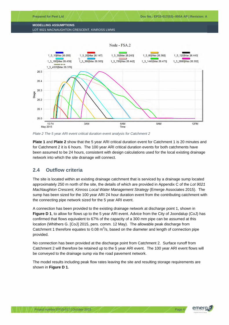
MODELLING ASSUMPTIONS
Prepared for Peet Ltd Doc No.: EP15-017(03)--005A AP | Revision: A
LOT 9021 MACNAUGHTON CRESCENT, KINROSS LWMS
Project number EP15-017 | October 2015 Page 4
Plate 2 The 5 year ARI event critical duration event analysis for Catchment 2
Plate 1 and Plate 2 show that the 5 year ARI critical duration event for Catchment 1 is 20 minutes and for Catchment 2 it is 6 hours. The 100 year ARI critical duration events for both catchments have been assumed to be 24 hours, consistent with design calculations used for the local existing drainage network into which the site drainage will connect.
2.4 Outflow criteria
The site is located within an existing drainage catchment that is serviced by a drainage sump located approximately 250 m north of the site, the details of which are provided in Appendix C of the Lot 9021 MacNaughton Crescent, Kinross Local Water Management Strategy (Emerge Associates 2015). The sump has been sized for the 100 year ARI 24 hour duration event from the contributing catchment with the connecting pipe network sized for the 5 year ARI event.
A connection has been provided to the existing drainage network at discharge point 1, shown in Figure D 1, to allow for flows up to the 5 year ARI event. Advice from the City of Joondalup (CoJ) has confirmed that flows equivalent to 67% of the capacity of a 300 mm pipe can be assumed at this location (Whithers G. [CoJ] 2015, pers. comm. 12 May). The allowable peak discharge from Catchment 1 therefore equates to 0.08 m3/s, based on the diameter and length of connection pipe provided.
No connection has been provided at the discharge point from Catchment 2. Surface runoff from Catchment 2 will therefore be retained up to the 5 year ARI event. The 100 year ARI event flows will be conveyed to the drainage sump via the road pavement network.
The model results including peak flow rates leaving the site and resulting storage requirements are shown in Figure D 1.

MODELLING ASSUMPTIONS
Prepared for Peet Ltd Doc No.: EP15-017(03)--005A AP | Revision: A
LOT 9021 MACNAUGHTON CRESCENT, KINROSS LWMS
Project number EP15-017 | October 2015
FIGURES
Figure D 1: Stormwater management plan

MODELLING ASSUMPTIONS
Prepared for Peet Ltd Doc No.: EP15-017(03)--005A AP | Revision: A
LOT 9021 MACNAUGHTON CRESCENT, KINROSS LWMS
Project number EP15-017 | October 2015
This page has been left blank intentionally.
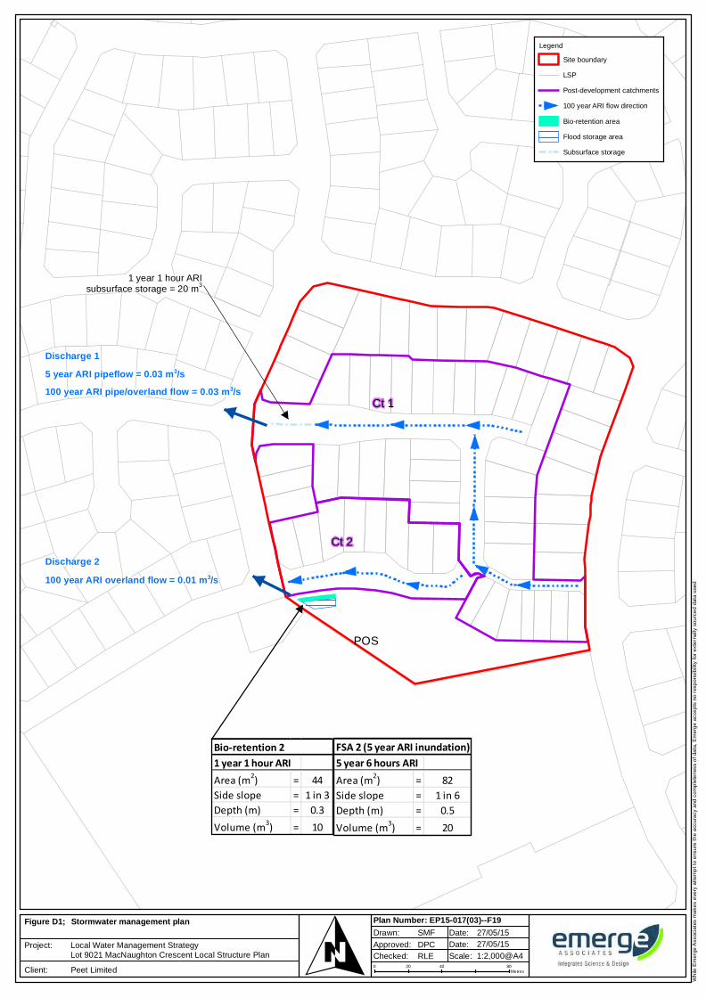
Wh
ile E
me
rge
Ass
ocia
tes
ma
kes
eve
ry a
tte
mp
t to
ens
ure
th
e a
ccu
racy
an
d c
om
ple
ten
ess
of
data
, E
me
rge
acc
ep
ts n
o r
esp
ons
ibili
ty f
or
ext
ern
ally
so
urc
ed
dat
a u
sed
0 40 8020Metres
1:2,000@A4Approved:
RLE
SMF
DPC
27/05/1527/05/15
Plan Number: EP15-017(03)--F19Drawn: Date:
Date:
Scale: Checked:OFigure D1;
Project:
Client:
Stormwater management plan
Local Water Management StrategyLot 9021 MacNaughton Crescent Local Structure Plan
Peet Limited
Legend
Site boundary
LSP
Post-development catchments
100 year ARI flow direction
Bio-retention area
Flood storage area
Subsurface storage
Ct 1
Ct 2
1 year 1 hour ARIArea (m2) = 44Side slope = 1 in 3Depth (m) = 0.3Volume (m3) = 10
Bio-retention 2
POS
5 year 6 hours ARIArea (m2) = 82Side slope = 1 in 6Depth (m) = 0.5Volume (m3) = 20
FSA 2 (5 year ARI inundation)
5 year ARI pipeflow = 0.03 m3/s100 year ARI pipe/overland flow = 0.03 m3/s
100 year ARI overland flow = 0.01 m3/s
Discharge 1
Discharge 2
1 year 1 hour ARIsubsurface storage = 20 m3

MODELLING ASSUMPTIONS
Prepared for Peet Ltd Doc No.: EP15-017(03)--005A AP | Revision: A
LOT 9021 MACNAUGHTON CRESCENT, KINROSS LWMS
Project number EP15-017 | October 2015
This page has been left blank intentionally.

LOCAL WATER MANAGEMENT STRATEGY
Prepared for Peet Ltd Doc No.: EP15-017(03)--001B RLE | Revision: B
LOT 9021 MACNAUGHTON CRESCENT LOCAL STRUCTURE PLAN, KINROSS
Project number EP15-017 | October 2015
APPENDIX E EARTHWORKS PLAN

LOCAL WATER MANAGEMENT STRATEGY
Prepared for Peet Ltd Doc No.: EP15-017(03)--001B RLE | Revision: B
LOT 9021 MACNAUGHTON CRESCENT LOCAL STRUCTURE PLAN, KINROSS
Project number EP15-017 | October 2015
This page has been left blank intentionally.