local optimisation of long anisotropic laminated fibre...
TRANSCRIPT
American Institute of Aeronautics and Astronautics
1
Local optimisation of long anisotropic laminated fibre composite
panels with T shape stiffeners
J. Enrique Herencia
* and Paul M. Weaver
†
University of Bristol,
Bristol BS8 1TR, UK
Mike I. Friswell ‡
University of Bristol,
Bristol BS8 1TR, UK
A method to locally optimise long anisotropic laminated fibre composite panels with T
shape stiffeners is presented. The technique splits the optimisation problem into two levels.
At the first level, composite optimisation is performed using mathematical programming
(MP), and the skin and stiffeners are modelled using lamination parameters that account for
their membrane and flexural anisotropy. Skin and stiffener laminates are assumed to be
symmetric, or mid-plane symmetric laminates, with 0, 90, 45, or -45 degree, ply angles. The
skin-stiffener configuration is further idealised as a group of flat plate laminates that are
rigidly connected. The panel is subjected to a combined case of loading under strength,
buckling and manufacturing constraints. At the second level, the actual skin and stiffener
lay-ups are obtained using a genetic algorithm (GA) and considering the ease of
manufacture. This approach offers the advantage of introducing accurate analysis methods
such as finite elements at the first level, without significant increases in processing time.
Furthermore modelling the laminate anisotropy enables the designer to explore and
potentially use elastic tailoring in a beneficial manner.
Nomenclature
a = panel length
A = membrane stiffness matrix, membrane
Aij = terms of the membrane stiffness matrix, i=j=1,2,6
Asf = area of the stiffener flange
Askin = area of the skin
Astg = area of the stiffener
Asw = area of the stiffener web
b = panel width
bsf = stiffener flange width
B = membrane-bending coupling stiffness matrix
c = continuous
C = compression
d = discrete
D = bending stiffness matrix, bending
Dc = bending stiffness of a skin-stiffener element
Dij = terms of the bending stiffness matrix, i=j=1,2,6
Eij = Young’s modulus in ij direction, i=j=1,2
EIc = longitudinal stiffness of a skin-stiffener element
Fc = longitudinal force applied at skin-stiffener centriod
* Marie Curie Research Assistant, Department of Aerospace Engineering, Queen’s Building,
AIAA Student Member. † Reader, Department of Aerospace Engineering, Queen’s Building, AIAA Member. ‡ Sir George White Professor of Aerospace Engineering, Department of Aerospace Engineering, Queen’s Building,
AIAA Member.
47th AIAA/ASME/ASCE/AHS/ASC Structures, Structural Dynamics, and Materials Confere1 - 4 May 2006, Newport, Rhode Island
AIAA 2006-2171
Copyright © 2006 by J.E. Herencia, P.M. Weaver and M.I. Friswell. Published by the American Institute of Aeronautics and Astronautics, Inc., with permission.
American Institute of Aeronautics and Astronautics
2
Gij = shear modulus i=1, j=2
Gi = ith design constraint swxyG = shear modules of the stiffener web
h = laminate thickness
hsw = stiffener web height
Ki = buckling coefficient in i direction, i=x,xy
M = mass of a skin-stiffener element, running moment vector
MS = middle-plane symmetric
N = running load vector
Ni = load per unit of width in i direction, i=x,y,xy
Nicr = critical load per unit of width, i= x,xy,wx,sh
Pcr = critical buckling load of a column accounting for transverse shear load
Pe = Euler buckling load
Qij = terms of the reduced stiffness matrix, i=j=1,2,6
RFij = reserve factor, i=px,pxy,pb,wb,cb,sb,cs,T,C; j=x,y,xy
S = symmetric
Skn = skin
Stg = stiffener flange and web
Stf = stiffener flange
Stw = stiffener web
t = thickness of the skin
ta = thickness of the stiffener flange
tsf = total thickness of the stiffener flange
tsw = total thickness of the stiffener web
tw = thickness of the stiffener web
T = tension
Ui = material invariants, i=1...5
Wi = weight, i=c,d
wfij = weighting factor for lamination parameters, i=1,2,3; j=A,D
xr = vector of design variables, abscise
yr = gene, ordinate
α,β,γ,δ = non-dimensional parameters
κ = middle-surface curvatures
εij = applied strain, i=T,C; j=x,y,xy
εaij = allowable strain, i=T,C; j=x,y,xy
λi = eigenvalue, i=b,s
ζ = tolerance value
νi = Poison’s ration in i direction, i=12,21
ρ = density
ξij = lamination parameters, i=1,2,3; j=A,D
ϕ = fibre orientation angle
θ, φψ , = encoded ply angle for the skin, the stiffener flange and web, respectively
I. Introduction
he use of composite materials as primary structures in the commercial aviation industry, has been gradually
increasing over the last decade. This has culminated in programmes such as the Airbus A3501 and the Boeing
7872, where composite materials will play a major role. Primary flight composite structures such as wings or
fuselages are mainly designed using stiffened panels. In general, composite materials present high specific strength
and stiffness ratios3. Furthermore, structures made of composite materials can be stiffness tailored potentially
offering a significant advantage over their metallic counterparts. This latter feature is intimately related to their
design and manufacture. Due to practical, yet often limiting, manufacturing considerations, laminated fibre
composite panels have been restricted to symmetric, or middle plane symmetric laminates, with 0, 90, 45, and -45
degree, ply angles. The manufacture of the T shape stiffeners adds an additional degree of complexity since it allows
the modification of the stiffener web and flange by adding extra and capping plies, respectively. This paper is
T
American Institute of Aeronautics and Astronautics
3
inspired by the desire to design elastically tailored stiffened composite panels that consider manufacturing
requirements, commonly used in the aerospace industry.
Over the years, optimisation techniques have been developed to assist engineers with composite design4-33. The
nature of composite optimisation is non-linear. In the seventies, early attempts on optimisation of laminated fibre
composites were performed by Schmit and Farshi4,5. They optimised symmetric laminated fibre composite materials
having homogeneous and orthotropic properties, considering the ply thicknesses as continuous variables. They
transformed the non-linear problem into a sequence of linear problems. In the same light, Stroud and Agranoff6
optimised composite hat-stiffened and corrugated panels using non-linear mathematical techniques with a simplified
set of buckling equations as constraints. The width and thickness of the elements of the dimensioned cross section
were the design variables. They assumed that the laminates were orthotropic. However, although designed carefully
composites might exhibit some degree of flexural anisotropy. Ashton7 initially showed the effect of the flexural
anisotropy on the stability of composite plates. Chamis8 concluded that neglecting flexural anisotropy of the
composite in the evaluation of buckling behaviour could lead to non-conservative results. Later, Nemeth9
characterised the importance of flexural anisotropy and provided bounds within which its effect would be
significant. Recently, Weaver10 developed closed form solutions to quantify the effect of flexural anisotropy on
compression loads. Flexural anisotropy is intrinsically related to laminate stacking sequence. The addressing of the
laminate stacking sequence and hence the identification of the number of plies of each fibre orientation, converts the
lay-up optimisation problem into a non-linear problem with discrete variables which a non-convex design space.
Tsai and Pagano11 and Tsai and Hann
12 gave an alternative representation of the stiffness properties of a
laminated fibre composite panel by the use of lamination parameters. Miki and Sugiyama13 proposed the use of
lamination parameters to deal with the discrete laminate stacking sequence problem. They assumed symmetric and
orthotropic laminates. Optimum designs for the required in-plane stiffness, buckling strength, and so on, were
obtained, from geometry relations between the lamination parameters feasible region and objective function.
Fukunaga and Vanderplats14 used lamination parameters and MP techniques to perform stiffness optimisation of
orthotropic laminated composites. Cylindrical shells under combined loading were used as a practical application.
Haftka and Walsh15 used integer programming techniques to carry out laminate stacking sequence optimisation
under buckling constraints on symmetric and balanced laminated plates. They used zero-one integers as design
variables that were related to stiffness properties via lamination parameters and showed that the problem was linear.
Flexural anisotropy was limited to manually modifying the optimum design and they used the branch and bound
method to solve the problem. Nagendra, Haftka and Gürdal16 extended the previous work and optimised the stacking
sequence of symmetric and balanced composite laminates with stability and strain constraints. Unfortunately, integer
programming techniques require large computational resources especially when structure complexity increases.
Fukunaga and Sekine17 presented an approach to maximise buckling loads under combined loading of symmetrically
laminated plates including the bending-twisting couplings or flexural anisotropy. They employed MP techniques and
the lamination parameters as design variables. They confirmed the detrimental effect of the flexural anisotropy on
the buckling load of panels under normal loading and highlighted that under shear and shear-normal loading flexural
anisotropy could increase or decrease the critical buckling load. Although an optimal laminate stacking sequence
with optimal fibre orientation was presented, neither discrete nor practical laminates were shown.
A different strategy was adopted by Le Riche and Haftka18 and later by Nagendra, Haftka and Gürdal
19,20. They
employed GAs to solve the integer stacking sequence problem. GAs are search algorithms based on the mechanics
of natural selection and natural genetics21, which do not require gradient information to perform the search. GAs are
widely used for their ability to tackle search spaces with many local optima22 and therefore a non convex design
space. Nagendra also investigated the application of a GA to the design of blade stiffened composite panels.
VIPASA23 was used as the analysis tool and results were compared with PASCO
24, which uses VIPASA as the
analysis tool and CONMIN25 as optimiser. It was concluded that the designs obtained by the GA offered higher
performance than the continuous designs. However, it was recognised that great computational cost was associated
with the GA.
Yamazaki26 initially proposed a two level optimisation strategy combining lamination parameters-MP and GAs.
The optimisation was split into two parts. Firstly, a gradient based optimisation was performed using the in-plane
and out-of-plane lamination parameters as design variables. Secondly, the lamination parameters from the first level
were targeted using a GA. In this paper, the volume, buckling load, deflection and natural frequencies of a
composite panel were optimised without accounting for either membrane or flexural anisotropy. Autio27 following a
American Institute of Aeronautics and Astronautics
4
similar approach, investigated actual lay-ups. The approach adopted was similar to Yamazaki, with the difference
being that commercial uni/multiaxil plies were considered and certain lay-up design rules were introduced as
penalties in the fitness function of the GA code. Earlier, Todoroki and Haftka28 proposed a more sophisticated
approach. They divided the optimisation into two stages. First, the lamination parameters were used in a continuous
optimisation to identify the neighbourhood of the optimum design. Subsequently a response surface approximation
was created in that neighbourhood and the GA was applied to that approximation. They applied this procedure to
buckling load maximisation of a composite plate. However, with the exception of Fukunaga and Vanderplats14, none
of the previous authors considered the feasible region in the lamination parameter space that relates in-plane,
coupling and out-of-plane lamination parameters.
Liu, Haftka and Trompette29 employed lamination parameters and defined the feasible region between two of the
four membrane and bending lamination parameters to maximise the buckling load of unstiffened composite panels
with restricted ply angles. They compared their approach against one using a GA and concluded that the use of
lamination parameters in a continuous optimisation produced similar results to those obtained by the GA except in
cases where laminates were thin or had low aspect ratios. Furthermore, Liu and Haftka30 proposed a single level
weight minimisation of composite wing structures using flexural lamination parameters. They assumed continuous
thicknesses for a set of restricted ply angles and two flexural lamination parameters, as design variables. Their
constraints were strength, buckling and the flexural lamination parameters domain. The wing consisted of several
unstiffened composite panels with orthotropic properties. They compared their work against a two level wing
optimisation strategy using GAs and concluded that both approaches produced similar results and that the single
level approach provided a lower bound to the true optima.
Diaconu and Sekine31 performed lay-up optimisation of laminated composite shells for maximisation of the
buckling load, using the lamination parameters as design variables and including their feasible region. They fully
defined, for the first time, the relations between the membrane, coupling and bending lamination parameters for ply
angles restricted to 0, 90, 45, and -45 degrees, in order to identify their feasible region within the design space. Note
that although developed independently from each other, their definition of the feasible region for the lamination
parameters was consistent with the one provided by Liu and Haftka30 (only defined for two membrane and bending
lamination parameters with ply angles restricted to 0, 90, 45, and -45 degrees).
The aim of the present paper is to provide an approach to locally optimise long anisotropic laminated fibre
composite panels with T shape stiffeners. The technique splits the optimisation problem into two levels. At the first
level, composite optimisation is performed using MP, the skin and stiffeners are modelled using lamination
parameters accounting for their membrane and flexural anisotropy. Skin and stiffener laminates are assumed to be
symmetric, or mid-plane symmetric laminates, with 0, 90, 45, or -45 degree, ply angles. The skin-stiffener
configuration is further idealised as a group of the flat laminated plates rigidly connected. The panel is subjected to a
combined case of loading under strength, buckling and manufacturing constraints. At the second level, the actual
skin and stiffener lay-ups are obtained using a GA and considering the ease of manufacture. This approach offers the
advantage of introducing accurate analysis methods such as finite elements at the first level, without significant
increases in processing time. Furthermore, modelling the laminate anisotropy enables the designer to explore and
potentially use elastic tailoring in a beneficial manner. The novelty of the current approach is based upon: the
inclusion of membrane and flexural anisotropy for elastic tailoring purposes; manufacturing constraints; practical
design constraints on lay-ups and the interaction between membrane and flexural lamination parameters for stiffened
panels.
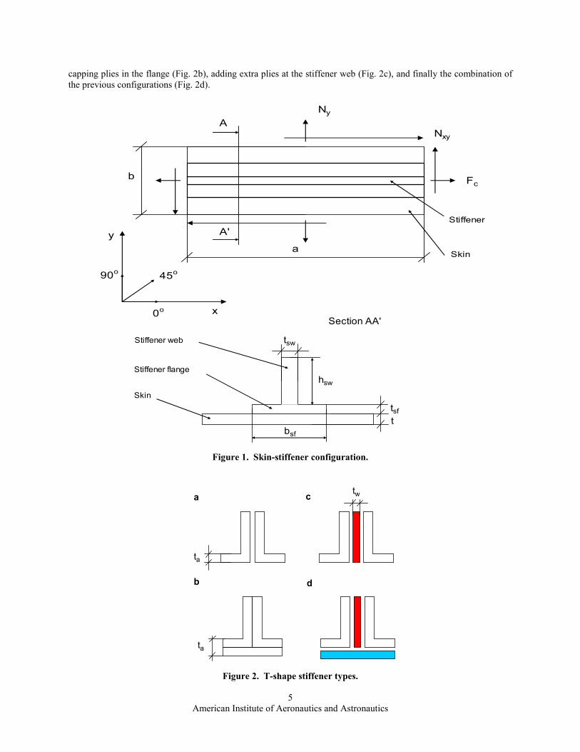
II. Panel geometry and loading
The composite stiffened panel is assumed to be wide and composed of a series of skin-stiffener configurations or
panels. Each local skin-stiffener panel consists of three flat plates that will be considered to be rigidly connected (all
degrees of freedom match at the interface), corresponding to the skin, stiffener flange and web, respectively. The
behaviour of the panel can be modelled by a skin-stiffener repeating element. Figure 1 defines the skin-stiffener
geometry, the material axis, and the positive sign convention for the loading.
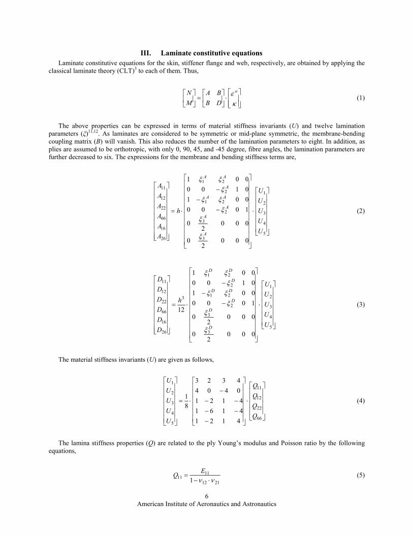
The geometry of the stiffener is affected by its design and manufacturing process. For this study four different
stiffener configurations were considered. The stiffener is manufactured as a back to back angle (Fig. 2a), considering
American Institute of Aeronautics and Astronautics
5
capping plies in the flange (Fig. 2b), adding extra plies at the stiffener web (Fig. 2c), and finally the combination of
the previous configurations (Fig. 2d).
Figure 1. Skin-stiffener configuration.
Figure 2. T-shape stiffener types.
b
a
Fc
Ny
Nxy
x
y
0o
45o90
o
A
A'
Stiffener
Skin
bsf
hsw
tsw
t
tsf
Skin
Stiffener web
Stiffener flange
Section AA'
twa
b
c
d
ta
ta
American Institute of Aeronautics and Astronautics
6
III. Laminate constitutive equations
Laminate constitutive equations for the skin, stiffener flange and web, respectively, are obtained by applying the
classical laminate theory (CLT)3 to each of them. Thus,
⋅
=
κε o
DB
BA
M
N (1)
The above properties can be expressed in terms of material stiffness invariants (U) and twelve lamination
parameters (ξ)11,12
. As laminates are considered to be symmetric or mid-plane symmetric, the membrane-bending
coupling matrix (B) will vanish. This also reduces the number of the lamination parameters to eight. In addition, as
plies are assumed to be orthotropic, with only 0, 90, 45, and -45 degree, fibre angles, the lamination parameters are
further decreased to six. The expressions for the membrane and bending stiffness terms are,
⋅
−
−
−
⋅=
5
4
3
2
1
3
3
2
21
2
21
26
16
66
22
12
11
0002
0
0002
0
1000
001
0100
001
U
U
U
U
U
h
A
A
A
A
A
A
A
A
A
AA
A
AA
ξ
ξξ
ξξξ
ξξ
(2)
⋅
−
−
−
⋅=
5
4
3
2
1
3
3
2
21
2
21
3
26
16
66
22
12
11
0002
0
0002
0
1000
001
0100
001
12
U
U
U
U
U
h
D
D
D
D
D
D
D
D
D
DD
D
DD
ξ
ξξξξξξξ
(3)
The material stiffness invariants (U) are given as follows,
⋅
−
−−
−−
−
⋅=
66
22
12
11
5
4
3
2
1
4121
4161
4121
0404
4323
8
1
Q
Q
Q
Q
U
U
U
U
U
(4)
The lamina stiffness properties (Q) are related to the ply Young’s modulus and Poisson ratio by the following
equations,
2112
1111
1 νν ⋅−=
EQ (5)
American Institute of Aeronautics and Astronautics
7
2112
221212
1 ννν
⋅−⋅
=E
Q (6)
2112
2222
1 νν ⋅−=
EQ (7)
1221 QQ = (8)
1266 GQ = (9)
11
221221
E
E⋅=νν (10)
The membrane and bending lamination parameters are calculated, respectively, by the following integrals,
[ ] [ ] dzh
h
h
A ⋅⋅= ∫−2
2
321 2sin4cos2cos1
ϕϕϕξ (11)
[ ] [ ] dzzh
h
h
D ⋅⋅⋅= ∫− 22
23321 2sin4cos2cos12
ϕϕϕξ (12)
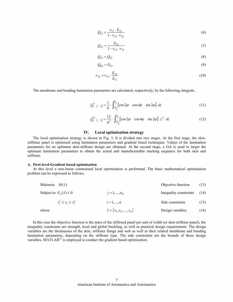
IV. Local optimisation strategy
The local optimisation strategy is shown in Fig. 3. It is divided into two stages. At the first stage, the skin-
stiffener panel is optimised using lamination parameters and gradient based techniques. Values of the lamination
parameters for an optimum skin-stiffener design are obtained. At the second stage, a GA is used to target the
optimum lamination parameters to obtain the actual and manufacturable stacking sequence for both skin and
stiffener.
A. First level-Gradient based optimisation
At this level a non-linear constrained local optimisation is performed. The basic mathematical optimisation
problem can be expressed as follows,
Minimise )(xMr Objective function (13)
Subject to 0)( ≤xG j
r Gnj ,....,1= Inequality constraints (14)
uii
li xxx ≤≤ ni ,....,1= Side constraints (15)
where { }nxxxx ,....,, 21=r
Design variables (16)
In this case the objective function is the mass of the stiffened panel per unit of width (or skin-stiffener panel), the
inequality constraints are strength, local and global buckling, as well as practical design requirements. The design
variables are the thicknesses of the skin, stiffener flange and web as well as their related membrane and bending
lamination parameters, depending on the stiffener type. The side constraints are the bounds of those design
variables. MATLAB32 is employed to conduct the gradient based optimisation.
American Institute of Aeronautics and Astronautics
8
Figure 3. Optimisation flow chart.
1. Objective function
The objective function is the mass of the skin-stiffener panel. The mass as a function of the design variables,
materials properties and geometry is given by,
( ))()()( xAxAaxM stgstgskinskin
rrr⋅+⋅⋅= ρρ (17)
where the skin and the stiffener area respectively, are defined as follows,
btAskin ⋅= (18)
swswsfsfswsfstg htbtAAA ⋅+⋅=+= (19)
2. Design variables
The design variables for a skin-stiffener panel, depending on the stiffener type are listed in Table 1.
For stiffener types a, c and d, sub-laminates are employed to calculate the membrane and bending stiffness
properties for the stiffener’s web (stiffener types a, c and d) and flange (stiffener type d), respectively.
1 Gradient based
optimisation
Loads GeometryMaterial
properties
2 GA
optimisation
1 level
Constraints
check
NO
YES
Final local
design
1 level Constraints
2 level Constraints
American Institute of Aeronautics and Astronautics
9
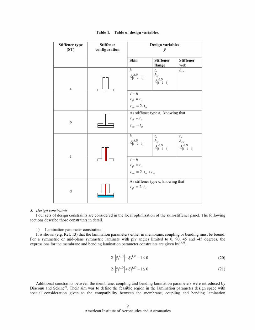
Table 1. Table of design variables.
Design variables
xr
Stiffener type
(ST)
Stiffener
configuration
Skin Stiffener
flange
Stiffener
web
h
[ ]DA,
321ξ
ta bsf
[ ]DA,
321ξ
hsw
a
ht =
asf tt =
asw tt ⋅= 2
b
As stiffener type a, knowing that
asf tt =
asw tt =
h
[ ]DA,
321ξ
ta bsf
[ ]DA,
321ξ
tw
hsw
[ ]DA,
321ξ
c
ht =
asf tt =
wasw ttt +⋅= 2
d
As stiffener type c, knowing that
asf tt ⋅= 2
3. Design constraints
Four sets of design constraints are considered in the local optimisation of the skin-stiffener panel. The following
sections describe those constraints in detail.
1) Lamination parameter constraints
It is shown (e.g. Ref. 13) that the lamination parameters either in membrane, coupling or bending must be bound.
For a symmetric or mid-plane symmetric laminate with ply angles limited to 0, 90, 45 and -45 degrees, the
expressions for the membrane and bending lamination parameter constraints are given by13,31
,
012 ,2
,1 ≤−−⋅ DADA ξξ (20)
012 ,2
,3 ≤−+⋅ DADA ξξ (21)
Additional constraints between the membrane, coupling and bending lamination parameters were introduced by
Diaconu and Sekine31. Their aim was to define the feasible region in the lamination parameter design space with
special consideration given to the compatibility between the membrane, coupling and bending lamination
American Institute of Aeronautics and Astronautics
10
parameters. Since there is a dependency between the membrane, coupling and bending properties, it is this
compatibility which enables the production of laminate designs that possess consistent properties. Accounting for
symmetric laminates and rearranging terms those expressions are,
( ) ( ) ( ) 011414
≤−⋅−⋅−− Ai
Di
Ai ξξξ 3,2,1=i (22)
( ) ( ) ( ) 011414
≤+⋅+⋅−+ Ai
Di
Ai ξξξ 3,2,1=i (23)
( ) ( ) ( ) 012121612 2121
4
21 ≤−−⋅⋅−−⋅⋅−−−⋅ AADDAA ξξξξξξ (24)
( ) ( ) ( ) 012121612 2121
4
21 ≤++⋅⋅++⋅⋅−++⋅ AADDAA ξξξξξξ (25)
( ) ( ) ( ) 032321632 2121
4
21 ≤+−⋅⋅+−⋅⋅−+−⋅ AADDAA ξξξξξξ (26)
( ) ( ) ( ) 032321632 2121
4
21 ≤−+⋅⋅−+⋅⋅−−+⋅ AADDAA ξξξξξξ (27)
( ) ( ) ( ) 012121612 2323
4
23 ≤+−⋅⋅+−⋅⋅−+−⋅ AADDAA ξξξξξξ (28)
( ) ( ) ( ) 012121612 2323
4
23 ≤−+⋅⋅−+⋅⋅−−+⋅ AADDAA ξξξξξξ (29)
( ) ( ) ( ) 032321632 2323
4
23 ≤−−⋅⋅−−⋅⋅−−−⋅ AADDAA ξξξξξξ (30)
( ) ( ) ( ) 032321632 2323
4
23 ≤++⋅⋅++⋅⋅−++⋅ AADDAA ξξξξξξ (31)
( ) ( ) ( ) 01141 3131
4
31 ≤−−⋅−−⋅−−− AADDAA ξξξξξξ (32)
( ) ( ) ( ) 01141 3131
4
31 ≤++⋅++⋅−++ AADDAA ξξξξξξ (33)
( ) ( ) ( ) 01141 3131
4
31 ≤+−⋅+−⋅−+− AADDAA ξξξξξξ (34)
( ) ( ) ( ) 01141 3131
4
31 ≤−+⋅−+⋅−−+ AADDAA ξξξξξξ (35)
The above constraints are imposed on the skin, stiffener flange and web laminates, respectively.
2) Strength constraints
Strength constraints are introduced to limit the magnitude of strains in tension, compression and shear taken by
the laminate. This is conducted in terms of allowable strains. Strains in x, y and xy directions are restrained. The
strains, under the applied in-plane loads, are calculated using CLT3. Hence,
⋅
=
−
xy
y
x
oxy
oy
ox
N
N
N
AAA
AAA
AAA1
662616
262212
161211
ε
εε
(36)
A reserve factor or ratio between the allowable and applied strain, is defined as
ji
jaij
iRFε
ε= CTi ,= ; xyyxj ,,= (37)
American Institute of Aeronautics and Astronautics
11
where T and C denote tension and compression, respectively. The strain constraints for both tension and
compression take the following expressions.
01 ≤− jiRF CTi ,= ; xyyxj ,,= (38)
These constraints are applied to the skin, stiffener flange and web laminates, respectively.
3) Buckling constraints
Buckling constraints are assessed in terms of local buckling (failure of the skin, the stiffener web or the local
skin-stiffener interaction) and global buckling (failure of the stiffened panel) criteria. Local and global buckling
constraints on anisotropic composite stiffened panels are considered using analytical (closed form solutions) and
numerical (finite elements) methods.
Closed Form (CF) solutions
This section describes closed form solutions used to assess the local and global buckling behaviour of an
anisotropic composite stiffened panel.
Local buckling
Local buckling of the skin and the stiffener, are considered separately assuming no interaction between them.
Buckling of the skin
The skin is assumed to be a long flat plate simply supported along the edges under normal and shear load.
Weaver10,33
has recently provided a comprehensive set of closed form solutions for long flexural anisotropic plates
under compression and shear loading. Note that in addition to presenting a closed form solution for the uniaxial
compression case, Weaver10 details a procedure to identify exactly the critical uniaxial compression load. Non-
dimensional parameters were used to calculate buckling coefficients, following Nemeth9, in order to obtain the
critical buckling load. The non-dimensional parameters (e.g. Ref. 9) are defined in terms of the flexural stiffness as
follows,
4
11
22
D
D=α ,
2211
6612 2
DD
DD +=β ,
422
311
16
DD
D=γ , and
4 32211
26
DD
D=δ (39)
Normal buckling
Weaver10 approximated the critical buckling load of a long anisotropic plate with simply supported conditions
along the edges and under normal loading as follows,
22112
2
DDb
KN xcrx
π= (40)
where Kx is a non-dimensional buckling coefficient given by,
( ) ( )( )( )
( )( )( )3
33
2
22
3
324
3
323212
+
+−+−
+
+++−+=
β
δγβγγδ
β
δγγββxK (41)
When γ and δ < 0.4, Kx is expected to give sufficient accuracy. For laminates with γ and δ > 0.4 an iteration scheme to calculate Kx is applied. For further details see Ref. 10.
The reserve factor for the uniaxial compression loading is given by,
American Institute of Aeronautics and Astronautics
12
x
crx
pxN
NRF = (42)
Shear buckling
Weaver33 defined the shear buckling coefficient in terms of the non-dimensional parameters as,
( ) ( )22225.0236.089.679.113.005.242.3 δγδγβδγββ +−++−−−+=xyK (43)
The critical shear buckling load has the following expression,
4 322112
2
DDKb
N xycrxy
π= (44)
The reserve factor for the shear loading is thus,
xy
crxy
pxyN
NRF = (45)
In the case of negative shear the shear buckling coefficient is calculated assuming that each ply angle is reversed
in sign. This is the same as changing the sign of the non-dimensional parameters δ and γ .
Normal-shear bucking interaction
The following formula34 is used to address the interaction,
2)(
111
pxypxpb RFRFRF+= (46)
The local buckling of the skin in terms of constraints is given by
01 ≤− pbRF (47)
Buckling of the stiffener web
The stiffener web is assumed to be a long flat plate simply supported along three edges (two short edges and one
long edge) and one edge free (long edge) under normal load. Herencia and Weaver35 have recently developed a
closed form solution for this loading case that includes the effects of flexural anisotropy. In this case, the critical
buckling load is given by,
−⋅=
22
226
662
12
D
DD
bN
crwx (48)
Note that when there is no flexural anisotropy the above formula reduces to the orthotropic expression36.
The reserve factor for the stiffener web instability is given by,
American Institute of Aeronautics and Astronautics
13
wx
crwx
wbN
NRF = (49)
Global buckling
Global panel buckling is considered by evaluating column buckling accounting for the shearing force induced at
the stiffener web, panel shear buckling and the interaction column-shear buckling.
Column buckling
The panel is assumed to behave as a wide column with pinned ends. The critical buckling load for this case
accounting for the shearing force induced at the stiffener web during buckling6,37 is given by,
swxysw
e
ecr
GA
P
PP
⋅+
=1
(50)
where
2
2
a
EIP ce
⋅=
π (51)
The reserve factor between the critical column load and applied load is defined as,
c
crcb
F
PRF = (52)
Shear buckling
The stiffened panel is assumed to be infinitely long with simply supported conditions along the long edges6. The
critical shear load is derived from Ref. 33 considering that the width of the plate (b) coincides with the length of the
stiffened panel (a) and the longitudinal and transversal bending stiffness of the stiffened panel are given,
respectively by,
2211 DD = (53)
b
EIDD c
c ==22 (54)
Substituting the above expressions into Eq. (44), the non-dimensional parameters can be calculated, and thus a
new shear buckling coefficient shK is found. Hence, the critical shear load is as follows,
422
3
2
2
DDKa
N cshcrsh
π= (55)
The reserve factor between the critical and applied shear load is defined as,
American Institute of Aeronautics and Astronautics
14
xy
crsh
sbN
NRF = (56)
In the case of negative shear, the shear buckling coefficient is calculated assuming that each ply angle is reversed
in sign, which is equivalent to changing the sign of the non-dimensional parameters δ and γ .
Column-shear buckling interaction
An interaction formula6 is used to address the overall buckling constraints. Hence,
2)(
111
shcbcs RFRFRF+= (57)
The global buckling of the stiffened panel in terms of constraints is given by
01 ≤− csRF (58)
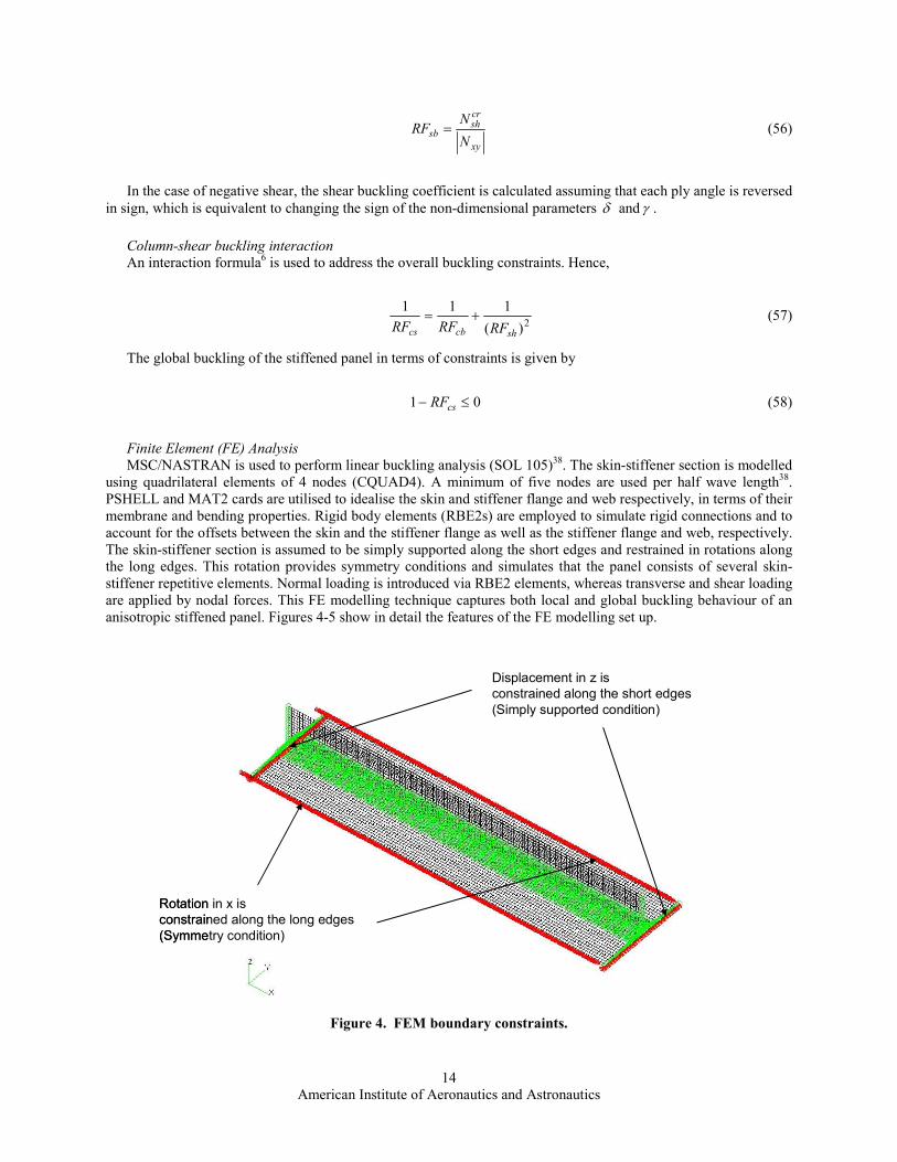
Finite Element (FE) Analysis
MSC/NASTRAN is used to perform linear buckling analysis (SOL 105)38. The skin-stiffener section is modelled
using quadrilateral elements of 4 nodes (CQUAD4). A minimum of five nodes are used per half wave length38.
PSHELL and MAT2 cards are utilised to idealise the skin and stiffener flange and web respectively, in terms of their
membrane and bending properties. Rigid body elements (RBE2s) are employed to simulate rigid connections and to
account for the offsets between the skin and the stiffener flange as well as the stiffener flange and web, respectively.
The skin-stiffener section is assumed to be simply supported along the short edges and restrained in rotations along
the long edges. This rotation provides symmetry conditions and simulates that the panel consists of several skin-
stiffener repetitive elements. Normal loading is introduced via RBE2 elements, whereas transverse and shear loading
are applied by nodal forces. This FE modelling technique captures both local and global buckling behaviour of an
anisotropic stiffened panel. Figures 4-5 show in detail the features of the FE modelling set up.
Figure 4. FEM boundary constraints.
Rotation in x is
constrained along the long edges
(Symmetry condition)
Displacement in z is
constrained along the short edges
(Simply supported condition)
Rotation in x is
constrained along the long edges
(Symmetry condition)
Displacement in z is
constrained along the short edges
(Simply supported condition)

American Institute of Aeronautics and Astronautics
15
Figure 5. FEM normal and shear loading.
4) Practical design constraints
Niu39 provided a comprehensive summary of design practices for composites. A reduced set of those rules are
used as design constraints. For a composite panel configuration the design considerations are addressed by limiting
the percentages of 0, 90, 45, and -45 degree, ply angles, the skin-stiffener flange Poisson’s ratio mismatch and skin
gauge. The design constraints are described in the following sections.
Percentages of ply angles
At least 10% of each ply orientation should be provided39. Maximum and minimum percentages of the ply
angles for the skin, stiffener flange and web are limited. The percentages of the 0, 90, 45, and -45 degree, ply angles
for each of those elements are,
1002
⋅⋅
=h
tp ii 45,45,90,0 −=i swsf ttth ,,= (59)
The maximum and minimum allowable ratios are given, respectively, by,
i
ipi
p
pRF
maxmax = (60)
and min
min
i
ipi
p
pRF = (61)
The maximum and minimum percentages of 0, 90, 45, and -45 degree, ply angles are implemented in terms of
design constraints as follows,
Shear loading
(Nodal forces)
Normal loading
(RBE2s Force @
skin-stiffener centriod)
Offsets
(RBE2s Skin-stiffener flange
& Stiffener flange-web)
Shear loading
(Nodal forces)
Normal loading
(RBE2s Force @
skin-stiffener centriod)
Offsets
(RBE2s Skin-stiffener flange
& Stiffener flange-web)
American Institute of Aeronautics and Astronautics
16
01max ≤− piRF (62)
011min
≤−piRF
(63)
Skin-stiffener flange Poisson’s ratio mismatch
The reduction of the Poisson’s ratio mismatch is critical in composite bonded structures39. The difference
between the skin and stiffener flange Poisson’s ratio is limited by a small number ζ to reduce the mismatch. An
acceptable value of ζ is assumed to be 0.05.
The Poisson’s ratio mismatch design constraint between the skin and stiffener flange is given by,
0≤−− ζνν stgfxy
skinxy (64)
Skin gauge
The minimum skin gauge is determined by the danger of a puncture due to lightning strike. Niu39 suggests a
minimum skin thicknesses of 3.81 mm. Skin gauge is addressed in terms of maximum and minimum skin thickness.
The maximum and minimum skin thickness ratios are given by,
t
tRFt
maxmax = (65)
and min
min
t
tRFt = (66)
Thus, the design constraints for the skin gauge are given by,
01 max ≤− tRF (67)
011min
≤−tRF
(68)
4. Sensitivities
When finite elements are used to provide the buckling constraints, sensitivities40,41
are supplied to MATLAB32 to
decrease the number of FE runs and to speed up the optimisation process. Buckling sensitivities are computed in
MSC/NASTRAN using the design sensitivity and optimisation solution (SOL 200)40. Strength, lamination parameter
and practical design constraints sensitivities are calculated by the forward finite difference approximation given by
( ) ( )j
iji
j
i
x
xGxxG
x
xG
∆
−∆+=
∂∂
rrr)(
(69)
where jx∆ is a small perturbation applied to the jth design variable. After a trial error exercise, a suitable step size
for the perturbation was determined as 0.0001.
B. Second level-GA based optimisation
A standard GA22,42
is employed at this level to solve the lay-up discrete optimisation problem. The lamination
parameters from the first optimisation level are targeted to obtain the laminate stacking sequence for the skin, the
American Institute of Aeronautics and Astronautics
17
stiffener flange and web, respectively. The GA is applied separately to the skin, stiffener flange and web. The
structure of a standard GA is well reported in the literature18-22,42
.
5. Fitness function
The fitness function is expressed in terms of the square difference between the optimum and the targeted
lamination parameters31. Extra penalty terms are added to account for design rules such as maximum plies of the
same orientation15-16,18-20,42
. Thus,
( ) ( ) k
ki
Diopt
Di
Di
i
Aiopt
Ai
Ai wfwfyf Θ+−⋅+−⋅= ∑∑∑
===
4
1
3
1
23
1
2)( ξξξξr
(70)
where yris the design variable vector or gene representing the laminate stacking sequence, DA
iwf , are weighting
factors and Θk are the penalty functions terms to limit the number of plies of the same orientation stacked together.
When more than 4 plies of the same orientation are stacked together (e.g. Ref. 14) the value of Θk is one otherwise is
zero.
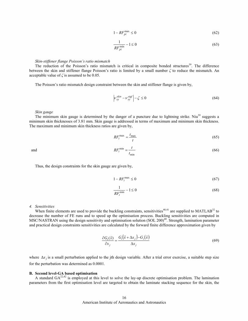
6. Genes
The design variables are the thickness and the 0, 90, 45, and -45 degree, ply angles that constitute the laminate
stacking sequences for the skin, stiffener flange and web. Those variables are encoded and modelled as
chromosomes in genes within the GA. The corresponding encoded chromosomes to ply angles are: 1, 2, 3, 4, 5, 6
and 7 for ± 45, 902, 02, 45, -45, 90 and 0 degrees, respectively. Figure 6 shows the modelling of the gene for the
skin. The total skin thickness is given by h, the encoded ply angle is θ and n corresponds to half or half plus one
plies if the skin laminate is symmetric or middle plane symmetric.
h θ1 θ2 … … θn-1 θn
7,6,5,4,3,2,1=iθ
Figure 6. Gene with chromosomes for skin.
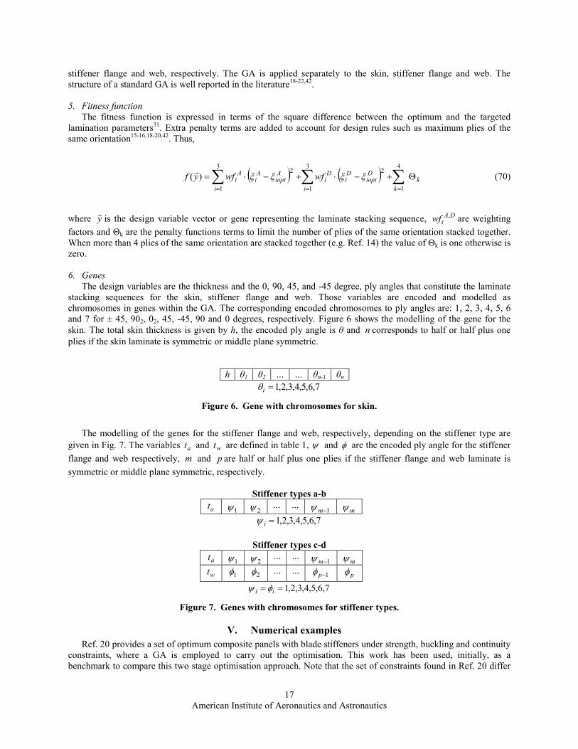
The modelling of the genes for the stiffener flange and web, respectively, depending on the stiffener type are
given in Fig. 7. The variables at and wt are defined in table 1, ψ and φ are the encoded ply angle for the stiffener flange and web respectively, m and p are half or half plus one plies if the stiffener flange and web laminate is
symmetric or middle plane symmetric, respectively.
Stiffener types a-b
at 1ψ 2ψ … …
1−mψ mψ
7,6,5,4,3,2,1=iψ
Stiffener types c-d
at 1ψ 2ψ … …
1−mψ mψ
wt 1φ 2φ … … 1−pφ pφ
7,6,5,4,3,2,1== ii φψ
Figure 7. Genes with chromosomes for stiffener types.
V. Numerical examples
Ref. 20 provides a set of optimum composite panels with blade stiffeners under strength, buckling and continuity
constraints, where a GA is employed to carry out the optimisation. This work has been used, initially, as a
benchmark to compare this two stage optimisation approach. Note that the set of constraints found in Ref. 20 differ
American Institute of Aeronautics and Astronautics
18
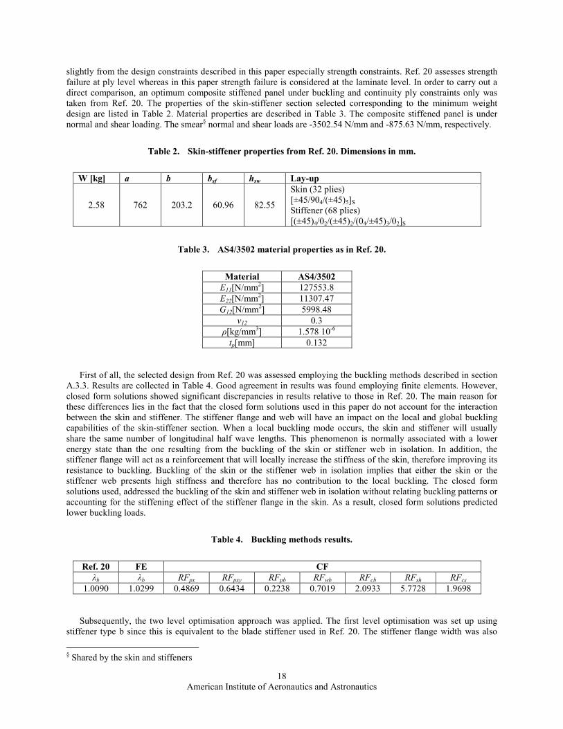
slightly from the design constraints described in this paper especially strength constraints. Ref. 20 assesses strength
failure at ply level whereas in this paper strength failure is considered at the laminate level. In order to carry out a
direct comparison, an optimum composite stiffened panel under buckling and continuity ply constraints only was
taken from Ref. 20. The properties of the skin-stiffener section selected corresponding to the minimum weight
design are listed in Table 2. Material properties are described in Table 3. The composite stiffened panel is under
normal and shear loading. The smear§ normal and shear loads are -3502.54 N/mm and -875.63 N/mm, respectively.
Table 2. Skin-stiffener properties from Ref. 20. Dimensions in mm.
W [kg] a b bsf hsw Lay-up
2.58 762 203.2 60.96 82.55
Skin (32 plies)
[±45/904/(±45)5]S
Stiffener (68 plies)
[(±45)4/02/(±45)2/(04/±45)3/02]S
Table 3. AS4/3502 material properties as in Ref. 20.
Material AS4/3502
E11[N/mm2] 127553.8
E22[N/mm2] 11307.47
G12[N/mm2] 5998.48
ν12 0.3
ρ[kg/mm3] 1.578 10
-6
tp[mm] 0.132
First of all, the selected design from Ref. 20 was assessed employing the buckling methods described in section
A.3.3. Results are collected in Table 4. Good agreement in results was found employing finite elements. However,
closed form solutions showed significant discrepancies in results relative to those in Ref. 20. The main reason for
these differences lies in the fact that the closed form solutions used in this paper do not account for the interaction
between the skin and stiffener. The stiffener flange and web will have an impact on the local and global buckling
capabilities of the skin-stiffener section. When a local buckling mode occurs, the skin and stiffener will usually
share the same number of longitudinal half wave lengths. This phenomenon is normally associated with a lower
energy state than the one resulting from the buckling of the skin or stiffener web in isolation. In addition, the
stiffener flange will act as a reinforcement that will locally increase the stiffness of the skin, therefore improving its
resistance to buckling. Buckling of the skin or the stiffener web in isolation implies that either the skin or the
stiffener web presents high stiffness and therefore has no contribution to the local buckling. The closed form
solutions used, addressed the buckling of the skin and stiffener web in isolation without relating buckling patterns or
accounting for the stiffening effect of the stiffener flange in the skin. As a result, closed form solutions predicted
lower buckling loads.
Table 4. Buckling methods results.
Ref. 20 FE CF
λb λb RFpx RFpxy RFpb RFwb RFcb RFsh RFcs
1.0090 1.0299 0.4869 0.6434 0.2238 0.7019 2.0933 5.7728 1.9698
Subsequently, the two level optimisation approach was applied. The first level optimisation was set up using
stiffener type b since this is equivalent to the blade stiffener used in Ref. 20. The stiffener flange width was also
§ Shared by the skin and stiffeners
American Institute of Aeronautics and Astronautics
19
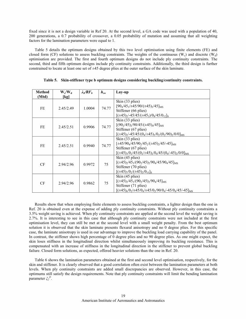
fixed since it is not a design variable in Ref 20. At the second level, a GA code was used with a population of 40,
200 generations, a 0.7 probability of crossover, a 0.05 probability of mutation and assuming that all weighting
factors for the lamination parameters were equal to 1.
Table 5 details the optimum designs obtained by this two level optimisation using finite elements (FE) and
closed form (CF) solutions to assess buckling constraints. The weights of the continuous (Wc) and discrete (Wd)
optimisation are provided. The first and fourth optimum designs do not include ply continuity constraints. The
second, third and fifth optimum designs include ply continuity constraints. Additionally, the third design is further
constrained to locate at least one set of ±45 degree plies at the outer surface of the skin laminate.
Table 5. Skin-stiffener type b optimum designs considering buckling/continuity constraints.
Method
(Mtd)
Wc/Wd
[kg]
λb/RFb hsw Lay-up
FE 2.45/2.49 1.0004 74.77
Skin (33 plies)
[904/453/±45/90/(±45)3/45]MS Stiffener (66 plies)
[(±45)2/-45/45/(±453)/08/45/012]S
FE 2.45/2.51 0.9906 74.77
Skin (33 plies)
[(902/45)2/90/45/(±45)4/45]MS Stiffener (67 plies)
[(±45)2/-45/45/(04/±45)3/02/(02/90)2/0/0]MS
FE 2.45/2.51 0.9940 74.77
Skin (33 plies)
[±45/904/45/902/452/(±45)2/45/-45]MS Stiffener (67 plies)
[(±45)3/02/45/(02/±45)2/04/45/(04/-45)2/0/0]MS
CF 2.94/2.96 0.9972 75
Skin (45 plies)
[(±45)2/453/(902/45)2/904/45/904/45]MS Stiffener (70 plies)
[(±45)7/02/(±45)2/015]S
CF 2.94/2.96 0.9862 75
Skin (45 plies)
[(±45)2/453/(902/45)2/904/45]MS
Stiffener (71 plies)
[(±45)6/02/±45/04/±45/02/90/04/-45/04/45/-45]MS
Results show that when employing finite elements to assess buckling constraints, a lighter design than the one in
Ref. 20 is obtained even at the expense of adding ply continuity constraints. Without ply continuity constraints a
3.5% weight saving is achieved. When ply continuity constraints are applied at the second level the weight saving is
2.7%. It is interesting to see in this case that although ply continuity constraints were not included at the first
optimisation level, they can still be met at the second level with a small weight penalty. From the best optimum
solution it is observed that the skin laminate presents flexural anisotropy and no 0 degree plies. For this specific
case, the laminate anisotropy is used in our advantage to improve the buckling load carrying capability of the panel.
In contrast, the stiffener shows high percentage of 0 degree plies and no 90 degree plies. As one might expect, the
skin loses stiffness in the longitudinal direction whilst simultaneously improving its buckling resistance. This is
compensated with an increase of stiffness in the longitudinal direction in the stiffener to prevent global buckling
failure. Closed form solutions, as expected, offered heavier solutions than the one in Ref. 20.
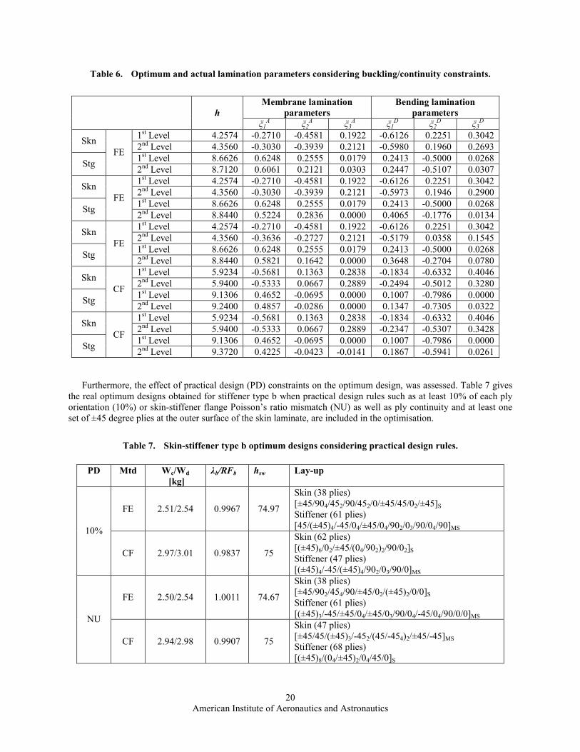
Table 6 shows the lamination parameters obtained at the first and second level optimisation, respectively, for the
skin and stiffener. It is clearly observed that a good correlation often exist between the lamination parameters at both
levels. When ply continuity constraints are added small discrepancies are observed. However, in this case, the
optimums still satisfy the design requirements. Note that ply continuity constraints will limit the bending lamination
parameter ξ2D.
American Institute of Aeronautics and Astronautics
20
Table 6. Optimum and actual lamination parameters considering buckling/continuity constraints.
Membrane lamination
parameters
Bending lamination
parameters
h ξ1
A ξ2
A ξ3
A ξ1
D ξ2
D ξ3
D
1st Level 4.2574 -0.2710 -0.4581 0.1922 -0.6126 0.2251 0.3042
Skn 2nd Level 4.3560 -0.3030 -0.3939 0.2121 -0.5980 0.1960 0.2693
1st Level 8.6626 0.6248 0.2555 0.0179 0.2413 -0.5000 0.0268
Stg
FE
2nd Level 8.7120 0.6061 0.2121 0.0303 0.2447 -0.5107 0.0307
1st Level 4.2574 -0.2710 -0.4581 0.1922 -0.6126 0.2251 0.3042
Skn 2nd Level 4.3560 -0.3030 -0.3939 0.2121 -0.5973 0.1946 0.2900
1st Level 8.6626 0.6248 0.2555 0.0179 0.2413 -0.5000 0.0268
Stg
FE
2nd Level 8.8440 0.5224 0.2836 0.0000 0.4065 -0.1776 0.0134
1st Level 4.2574 -0.2710 -0.4581 0.1922 -0.6126 0.2251 0.3042
Skn 2nd Level 4.3560 -0.3636 -0.2727 0.2121 -0.5179 0.0358 0.1545
1st Level 8.6626 0.6248 0.2555 0.0179 0.2413 -0.5000 0.0268
Stg
FE
2nd Level 8.8440 0.5821 0.1642 0.0000 0.3648 -0.2704 0.0780
1st Level 5.9234 -0.5681 0.1363 0.2838 -0.1834 -0.6332 0.4046
Skn 2nd Level 5.9400 -0.5333 0.0667 0.2889 -0.2494 -0.5012 0.3280
1st Level 9.1306 0.4652 -0.0695 0.0000 0.1007 -0.7986 0.0000
Stg
CF
2nd Level 9.2400 0.4857 -0.0286 0.0000 0.1347 -0.7305 0.0322
1st Level 5.9234 -0.5681 0.1363 0.2838 -0.1834 -0.6332 0.4046
Skn 2nd Level 5.9400 -0.5333 0.0667 0.2889 -0.2347 -0.5307 0.3428
1st Level 9.1306 0.4652 -0.0695 0.0000 0.1007 -0.7986 0.0000
Stg
CF
2nd Level 9.3720 0.4225 -0.0423 -0.0141 0.1867 -0.5941 0.0261
Furthermore, the effect of practical design (PD) constraints on the optimum design, was assessed. Table 7 gives
the real optimum designs obtained for stiffener type b when practical design rules such as at least 10% of each ply
orientation (10%) or skin-stiffener flange Poisson’s ratio mismatch (NU) as well as ply continuity and at least one
set of ±45 degree plies at the outer surface of the skin laminate, are included in the optimisation.
Table 7. Skin-stiffener type b optimum designs considering practical design rules.
PD Mtd Wc/Wd
[kg]
λb/RFb hsw Lay-up
FE 2.51/2.54 0.9967 74.97
Skin (38 plies)
[±45/904/452/90/452/0/±45/45/02/±45]S
Stiffener (61 plies)
[45/(±45)4/-45/04/±45/04/902/03/90/04/90]MS 10%
CF 2.97/3.01 0.9837 75
Skin (62 plies)
[(±45)6/02/±45/(04/902)2/90/02]S Stiffener (47 plies)
[(±45)4/-45/(±45)4/902/03/90/0]MS
FE 2.50/2.54 1.0011 74.67
Skin (38 plies)
[±45/902/454/90/±45/02/(±45)2/0/0]S Stiffener (61 plies)
[(±45)3/-45/±45/04/±45/03/90/04/-45/04/90/0/0]MS NU
CF 2.94/2.98 0.9907 75
Skin (47 plies)
[±45/45/(±45)3/-452/(45/-454)2/±45/-45]MS Stiffener (68 plies)
[(±45)8/(04/±45)2/04/45/0]S
American Institute of Aeronautics and Astronautics
21
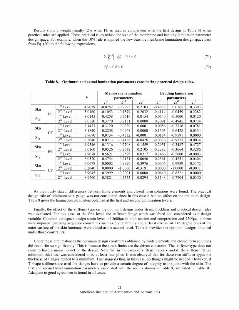
Results show a weight penalty (2% when FE is used in comparison with the first design in Table 5) when
practical rules are applied. Those practical rules reduce the size of the membrane and bending lamination parameter
design space. For example, when the 10% rule is applied the new feasible membrane lamination design space pass
from Eq. (20) to the following expressions,
06.02 21 ≤−−⋅ AA ξξ (71)
08.02 ≤−Aξ (72)
Table 8. Optimum and actual lamination parameters considering practical design rules.
Membrane lamination
parameters
Bending lamination
parameters
h ξ1
A ξ2
A ξ3
A ξ1
D ξ2
D ξ3
D
1st Level 4.9039 -0.0252 -0.2293 0.2103 -0.4878 0.0165 0.3393
Skn 2nd Level 5.0160 -0.1053 -0.1579 0.2632 -0.4114 -0.0459 0.2282
1st Level 8.0145 0.4258 0.2516 0.0154 0.0540 -0.5000 0.0120
Stg
FE
2nd Level 8.0520 0.3770 0.2131 0.0000 0.2091 -0.4945 0.0734
1st Level 8.1473 0.3120 0.0239 0.0001 0.0056 -0.7316 0.0781
Skn 2nd Level 8.1840 0.2258 0.0968 0.0000 0.1303 -0.6428 0.0334
1st Level 5.9670 0.0734 -0.4532 -0.0001 0.0184 -0.9591 0.0000
Stg
CF
2nd Level 6.2040 0.0213 -0.4468 -0.0426 -0.0076 -0.9577 0.0034
1st Level 4.9546 0.1316 -0.2708 0.1559 -0.2951 -0.3487 0.4727
Skn 2nd Level 5.0160 0.0526 -0.2632 0.2105 -0.2282 -0.3664 0.3286
1st Level 7.9078 0.5621 0.2599 0.0217 0.2466 -0.5000 -0.0003
Stg
FE
2nd Level 8.0520 0.4754 0.2131 -0.0656 0.2561 -0.4251 -0.0404
1st Level 6.0678 -0.0002 -0.9996 -0.3976 -0.0006 -0.9989 0.3172
Skn 2nd Level 6.2040 0.0000 -1.0000 -0.3191 0.0000 -1.0000 -0.0071
1st Level 8.9045 0.3999 -0.2001 0.0000 0.0640 -0.8721 0.0000
Stg
CF
2nd Level 8.9760 0.3824 -0.2353 0.0294 0.1148 -0.7704 0.0350
As previously stated, differences between finite elements and closed form solutions were found. The practical
design rule of minimum skin gauge was not considered since in this case it had no effect on the optimum design.
Table 8 gives the lamination parameters obtained at the first and second optimisation levels.
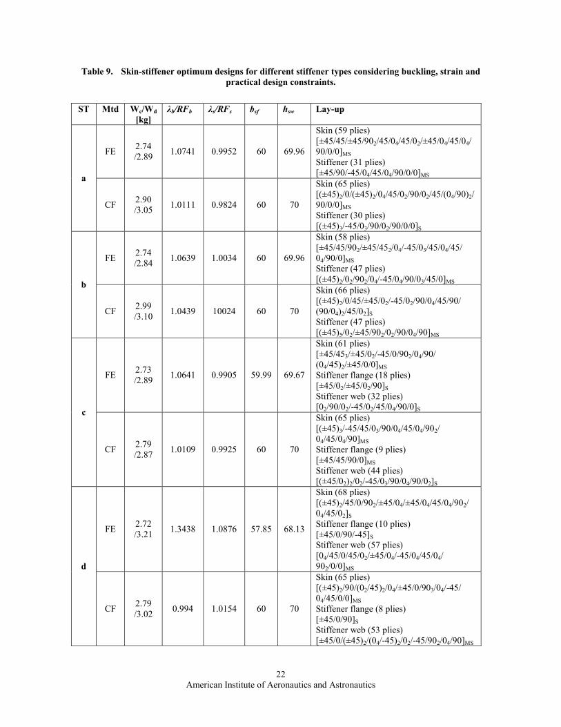
Finally, the effect of the stiffener type on the optimum design under strain, buckling and practical design rules
was evaluated. For this case, at the first level, the stiffener flange width was freed and considered as a design
variable. Common aerospace design strain levels of 3600µε in both tension and compression and 7200µε in shear were imposed. Stacking sequence constraints such as ply continuity and at least one set of ±45 degree plies at the
outer surface of the skin laminate, were added at the second level. Table 9 provides the optimum designs obtained
under those constraints.
Under these circumstances the optimum design constraints obtained by finite elements and closed form solutions
did not differ so significantly. This is because the strain limits are the driven constraint. The stiffener type does not
seem to have a major impact on the design. Note that in the cases of stiffener types c and d, the stiffener flange
minimum thickness was considered to be at least four plies. It was observed that for these two stiffener types the
thickness of flanges tended to a minimum. That suggests that, in this case, no flanges might be needed. However, if
T shape stiffeners are used the flanges have to provide a certain degree of integrity to the joint with the skin. The
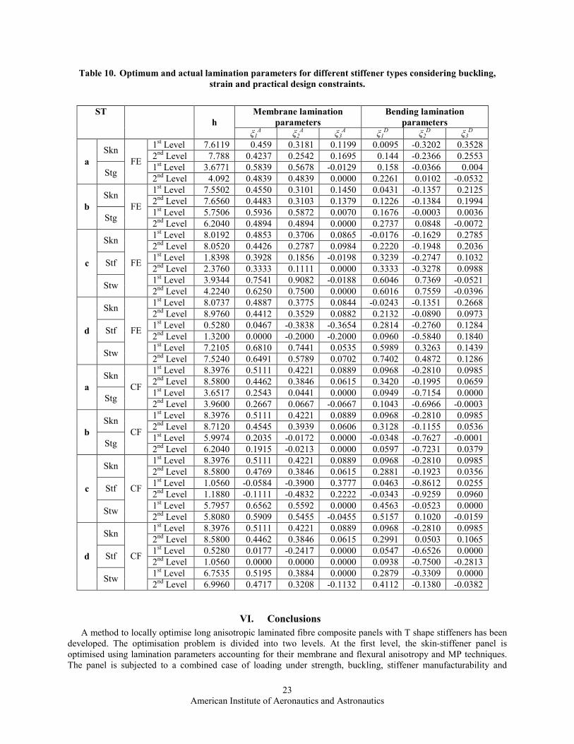
first and second level lamination parameters associated with the results shown in Table 9, are listed in Table 10.
Adequate to good agreement is found in all cases.
American Institute of Aeronautics and Astronautics
22
Table 9. Skin-stiffener optimum designs for different stiffener types considering buckling, strain and
practical design constraints.
ST Mtd Wc/Wd
[kg]
λb/RFb λs/RFs bsf hsw Lay-up
FE 2.74
/2.89 1.0741 0.9952 60 69.96
Skin (59 plies)
[±45/45/±45/902/45/04/45/02/±45/04/45/04/
90/0/0]MS Stiffener (31 plies)
[±45/90/-45/04/45/04/90/0/0]MS a
CF 2.90
/3.05 1.0111 0.9824 60 70
Skin (65 plies)
[(±45)2/0/(±45)2/04/45/02/90/02/45/(04/90)2/
90/0/0]MS
Stiffener (30 plies)
[(±45)3/-45/03/90/02/90/0/0]S
FE 2.74
/2.84 1.0639 1.0034 60 69.96
Skin (58 plies)
[±45/45/902/±45/452/04/-45/03/45/04/45/
04/90/0]MS Stiffener (47 plies)
[(±45)2/02/902/04/-45/04/90/03/45/0]MS b
CF 2.99
/3.10 1.0439 10024 60 70
Skin (66 plies)
[(±45)2/0/45/±45/02/-45/02/90/04/45/90/
(90/04)2/45/02]S
Stiffener (47 plies)
[(±45)5/02/±45/902/02/90/04/90]MS
FE 2.73
/2.89 1.0641 0.9905 59.99 69.67
Skin (61 plies)
[±45/453/±45/02/-45/0/902/04/90/
(04/45)2/±45/0/0]MS
Stiffener flange (18 plies)
[±45/02/±45/02/90]S
Stiffener web (32 plies)
[02/90/02/-45/02/45/04/90/0]S c
CF 2.79
/2.87 1.0109 0.9925 60 70
Skin (65 plies)
[(±45)3/-45/45/03/90/04/45/04/902/
04/45/04/90]MS
Stiffener flange (9 plies)
[±45/45/90/0]MS
Stiffener web (44 plies)
[(±45/02)2/02/-45/03/90/04/90/02]S
FE 2.72
/3.21 1.3438 1.0876 57.85 68.13
Skin (68 plies)
[(±45)2/45/0/902/±45/04/±45/04/45/04/902/
04/45/02]S
Stiffener flange (10 plies)
[±45/0/90/-45]S
Stiffener web (57 plies)
[04/45/0/45/02/±45/04/-45/04/45/04/ 902/0/0]MS d
CF 2.79
/3.02 0.994 1.0154 60 70
Skin (65 plies)
[(±45)2/90/(02/45)2/04/±45/0/903/04/-45/
04/45/0/0]MS
Stiffener flange (8 plies)
[±45/0/90]S
Stiffener web (53 plies)
[±45/0/(±45)2/(04/-45)2/02/-45/902/04/90]MS
American Institute of Aeronautics and Astronautics
23
Table 10. Optimum and actual lamination parameters for different stiffener types considering buckling,
strain and practical design constraints.
Membrane lamination
parameters
Bending lamination
parameters
ST
h
ξ1A ξ2
A ξ3
A ξ1
D ξ2
D ξ3
D
1st Level 7.6119 0.459 0.3181 0.1199 0.0095 -0.3202 0.3528
Skn 2nd Level 7.788 0.4237 0.2542 0.1695 0.144 -0.2366 0.2553
1st Level 3.6771 0.5839 0.5678 -0.0129 0.158 -0.0366 0.004
a
Stg
FE
2nd Level 4.092 0.4839 0.4839 0.0000 0.2261 0.0102 -0.0532
1st Level 7.5502 0.4550 0.3101 0.1450 0.0431 -0.1357 0.2125
Skn 2nd Level 7.6560 0.4483 0.3103 0.1379 0.1226 -0.1384 0.1994
1st Level 5.7506 0.5936 0.5872 0.0070 0.1676 -0.0003 0.0036
b
Stg
FE
2nd Level 6.2040 0.4894 0.4894 0.0000 0.2737 0.0848 -0.0072
1st Level 8.0192 0.4853 0.3706 0.0865 -0.0176 -0.1629 0.2785
Skn 2nd Level 8.0520 0.4426 0.2787 0.0984 0.2220 -0.1948 0.2036
1st Level 1.8398 0.3928 0.1856 -0.0198 0.3239 -0.2747 0.1032
Stf 2nd Level 2.3760 0.3333 0.1111 0.0000 0.3333 -0.3278 0.0988
1st Level 3.9344 0.7541 0.9082 -0.0188 0.6046 0.7369 -0.0521
c
Stw
FE
2nd Level 4.2240 0.6250 0.7500 0.0000 0.6016 0.7559 -0.0396
1st Level 8.0737 0.4887 0.3775 0.0844 -0.0243 -0.1351 0.2668
Skn 2nd Level 8.9760 0.4412 0.3529 0.0882 0.2132 -0.0890 0.0973
1st Level 0.5280 0.0467 -0.3838 -0.3654 0.2814 -0.2760 0.1284
Stf 2nd Level 1.3200 0.0000 -0.2000 -0.2000 0.0960 -0.5840 0.1840
1st Level 7.2105 0.6810 0.7441 0.0535 0.5989 0.3263 0.1439
d
Stw
FE
2nd Level 7.5240 0.6491 0.5789 0.0702 0.7402 0.4872 0.1286
1st Level 8.3976 0.5111 0.4221 0.0889 0.0968 -0.2810 0.0985
Skn 2nd Level 8.5800 0.4462 0.3846 0.0615 0.3420 -0.1995 0.0659
1st Level 3.6517 0.2543 0.0441 0.0000 0.0949 -0.7154 0.0000
a
Stg
CF
2nd Level 3.9600 0.2667 0.0667 -0.0667 0.1043 -0.6966 -0.0003
1st Level 8.3976 0.5111 0.4221 0.0889 0.0968 -0.2810 0.0985
Skn 2nd Level 8.7120 0.4545 0.3939 0.0606 0.3128 -0.1155 0.0536
1st Level 5.9974 0.2035 -0.0172 0.0000 -0.0348 -0.7627 -0.0001
b
Stg
CF
2nd Level 6.2040 0.1915 -0.0213 0.0000 0.0597 -0.7231 0.0379
1st Level 8.3976 0.5111 0.4221 0.0889 0.0968 -0.2810 0.0985
Skn 2nd Level 8.5800 0.4769 0.3846 0.0615 0.2881 -0.1923 0.0356
1st Level 1.0560 -0.0584 -0.3900 0.3777 0.0463 -0.8612 0.0255
Stf 2nd Level 1.1880 -0.1111 -0.4832 0.2222 -0.0343 -0.9259 0.0960
1st Level 5.7957 0.6562 0.5592 0.0000 0.4563 -0.0523 0.0000
c
Stw
CF
2nd Level 5.8080 0.5909 0.5455 -0.0455 0.5157 0.1020 -0.0159
1st Level 8.3976 0.5111 0.4221 0.0889 0.0968 -0.2810 0.0985
Skn 2nd Level 8.5800 0.4462 0.3846 0.0615 0.2991 0.0503 0.1065
1st Level 0.5280 0.0177 -0.2417 0.0000 0.0547 -0.6526 0.0000
Stf 2nd Level 1.0560 0.0000 0.0000 0.0000 0.0938 -0.7500 -0.2813
1st Level 6.7535 0.5195 0.3884 0.0000 0.2879 -0.3309 0.0000
d
Stw
CF
2nd Level 6.9960 0.4717 0.3208 -0.1132 0.4112 -0.1380 -0.0382
VI. Conclusions
A method to locally optimise long anisotropic laminated fibre composite panels with T shape stiffeners has been
developed. The optimisation problem is divided into two levels. At the first level, the skin-stiffener panel is
optimised using lamination parameters accounting for their membrane and flexural anisotropy and MP techniques.
The panel is subjected to a combined case of loading under strength, buckling, stiffener manufacturability and
American Institute of Aeronautics and Astronautics
24
practical design rules. Skin and stiffener laminates are assumed to be symmetric, or mid-plane symmetric laminates
with 0, 90, 45, or -45 degree, ply angles. Values of the lamination parameters for an optimum skin-stiffener design
are obtained. At the second level, a GA code is used to target the optimum lamination parameters to find the actual
stacking sequence for both skin and stiffener considering ply continuity and stiffener manufacture.
This two level approach has shown good performance when compared with other work (Ref. 20). Optimised
panels obtained under buckling and ply continuity constraints here are approximately 2.7% lighter than those
optimised and reported in Ref. 20. The inclusion of membrane and flexural anisotropy in the optimisation procedure
herein has enabled more designs to be explored. As such, elastic tailoring has been used to an advantage. Employing
finite elements to assess buckling behaviour has highlighted the importance of considering skin-stiffener interaction.
Closed form solutions did not consider this interaction and the resulting structures were heavier. However, closed
form solutions provide the designer with a valuable understanding of the buckling constraints.
When considering practical design rules, slight weight penalties have been observed. If the design is driven by
strain constraints, the use of finite elements or closed form solutions to evaluate buckling response has shown
similar results. Stiffener manufacture does not seem to have a major impact on weight when the design is strain
driven. However, it might affect the design when buckling considerations are the driving constraint.
In general, good agreement has been found between the lamination parameters obtained at the first level and
those determined from the second level (where the actual stacking sequence is identified). Note that although
sometimes the lamination parameters at both levels do not completely match, good designs have still been produced.
It is also clear that the designs at the first level will always be lighter than the second level designs since at the latter
level a rounding process occurs.
The computational cost associated with both gradient and GA optimisation was acceptable in this study.
Furthermore, it is hoped that this two level optimisation approach will be a module within a global optimisation
procedure that could perform elastic tailoring in more complex structures.
Acknowledgments Authors thank the EC for the Marie-Curie Excellence Grant. J.E. Herencia thanks Tim Edwards and Yoann
Bonnefon, for their interest, help and valuable comments especially on finite elements as well as Mike Coleman and
Andrew Main for their assistance on the creation of finite elements models. J.E. Herencia and P.M. Weaver thank
Cezar Diaconu for his contribution and support, particularly on lamination parameters. J.E. Herencia thanks Mark
Lillico for his comments on the modelling of stiffened panels. J.E. Herencia thanks Imran Khawaja, Alastair Tucker,
Stuart King, Pedro Raposo and Paul Harper for their general remarks.
References 1http://www.airbus.com/en/presscentre/pressreleases/10_dec_04_A350_ATO.html [cited 25 July 2005]. 2http://www.newairplane.com/en-US/Extras/TechnologySpotlight/composite.htm [cited 25 July 2005]. 3Jones, R. M. “Mechanics of composite materials”. 2nd edition. Taylor and Francis,Inc.,325 Chestnut street, Philadelphia, PA
19106. pp.26-31. 1999. 4Schmit, L. A and Farshi, B. “Optimum laminate design for strength and stiffness”. International journal for numerical
methods in engineering, Vol. 7, pp.519-536. 1973. 5Schmit, L. A and Farshi, B. “Optimum design of laminated fibre composite plates”. International journal for numerical
methods in engineering, Vol. 11, pp.623-640. 1977. 6Stroud, W. J. and Agranoff, N. “Minimum mass design of filamentary composite panels under combined loads: design
procedure based on simplified equations”. NASA TN D-8257. NASA, Langley research centre, Hampton, Va. 23665. 1976. 7Ashton, J. E. and Waddoups, M. E. “Analysis of anisotropic plates”. Journal of composite materials, Vol. 3, pp.148-165.
1969. 8Chamis, C. C. “Buckling of anisotropic composite plates”. Journal of the structural division, Proceedings of the ASCE. Vol.
95, ST10, pp.2119-p2139. 1969. 9Nemeth, M. P. “Importance of anisotropy on buckling of compression-loaded symmetric composite plates”. AIAA journal,
Vol. 24, No. 11, pp.1831-1835. Nov. 1986. 10Weaver, P.M. “Approximate analysis for buckling of compression loaded long rectangular plates with flexural/twist
anisotropy”. Proceedings of the Royal Society of A: Mathematical, Physical and Engineering Sciences. Vol. 462, No. 2065,
2006. 11Tsai, S. W., Halpin, J. C. and Pagano, N. J. “Composite materials workshop”. Technomic publishing Co., Inc., 750 Summer
St., Stamford, Conn. 06902. pp.233-253. 1968.
American Institute of Aeronautics and Astronautics
25
12Tsai, S. W. and Hahn, H. T. “Introduction to composite materials”. Technomic publishing Co., Inc., 750 Summer St.,
Stamford, Conn. 06902. 1980. 13Miki, M. and Sugiyama, Y. “Optimum design of laminated composite plates using lamination parameters”. AIAA-91-0971-
CP. 1991. 14Fukunaga, H. and Vanderplaats, G. N. “Stiffness optimisation of orthotropic laminated composites using lamination
parameters”. AIAA journal, Vol. 29, No. 4, pp.641-646. 1991. 15Haftka, R. T. and Walsh, J. L. “Stacking sequence optimisation for buckling of laminated plates by integer programming”.
AIAA journal, Vol. 30, No. 3, pp.814-819. 1992. 16Nagendra, S., Haftka, R. T. and Gürdal, Z. “Stacking sequence optimisation of simple supported laminates with stability
and strain constraints”. AIAA journal, Vol. 30, No. 8, pp.2132-2137. 1992. 17Fukunaga, H., Sekine, H., Sato, M. and IiNo, A. “Buckling design of symmetrically laminated plates using lamination
parameters”. Computers and structures, Vol. 57, No. 4, pp.643-649. 1995. 18Le Riche, R. and Haftka, R. T. “Optimisation of laminate stacking sequence for buckling load maximisation by genetic
algorithm”. AIAA journal, Vol. 31, No. 5. 1993. 19Nagendra, S., Haftka, R. T. and Gürdal, Z. ”Design of a blade stiffened composite panel by a genetic algorithm”. AIAA-93-
1584-CP. 1993. 20Nagendra, S., Jestin, D., Gürdal, Z, Haftka, R. T. and Watson, L. T. “Improved genetic algorithm for the design of stiffened
composite panels”. Computers and structures, Vol. 58, No. 3, pp.543-555. 1996. 21Goldberg, D. E. “Genetic algorithms in search, optimisation and machine learning. Addison Wesley Longman, Inc. 1989. 22Coley, D. A. “An introduction to genetic algorithms for scientist and engineers”. World Scientific Publishing Co. Pte. Ltd.,
P. O. Box 128, Farrer Rd, Singapore 912805. 1999. 23Wittrick, W. H. and Williams, F. W. “Buckling and vibration of anisotropic or isotropic plate assemblies under combined
loadings”. Int. J. mech. Sci. Pergamon Press. Vol. 16, pp.209-239. 1974. 24Anderson, M. S. and Stroud, W. J. “A general panel sizing computer code and its application to composite structural
panels”. AIAA journal, Vol.17, No.8, pp.892-897. 1979. 25Vanderplaats, G. N. “A fortran program for constrained function minimization: User's manual”. NASA-TM-X-62282.
1973. 26Yamazaki, K. “Two-level optimisation technique of composite laminate panels by genetic algorithms”. AIAA-96-1539-CP.
1996. 27Autio, M. “Determining the real lay-up of a laminate corresponding to optimal lamination parameters by genetic search”.
Struct. multidisc. optim. Vol. 20, pp.301-310. 2000. 28Todoroki, A. and Haftka, R. T. “Lamination parameters for efficient genetic optimisation of the stacking sequences of
composite panels”. AIAA-98-4816. 1998. 29Liu, B., Haftka R. T. and Trompette P. “Maximisation of buckling loads of composite panels using flexural lamination
parameters”. Struct. multidisc. optim. Vol.26, pp.28-36. 2004. 30Liu, B. and Haftka R. T. “Single level composite wing optimisation based on flexural lamination parameters”. B. Liu, R. T.
Haftka. Struct. multidisc. optim. Vol.26, pp.111-120. 2004. 31Diaconu, C. G. and Sekine, H. “Layup optimisation for buckling of laminated composite shells with restricted layer
angles”. AIAA journal, Vol. 42, No. 10, pp.2153-2163. 2004. 32MATLAB software V.7.1. The MathWorks, Inc. 1994-2006.
33Weaver, P. M. “On optimisation of long anisotropic flat plates subject to shear buckling loads”. 45th
AIAA/ASME/ASCE/AHS/ACS Structures, Structural Dynamics & Materials Conference, 19-22 April 2004, Palm Springs,
California. 34Lekhnitskii , S. G. “Anisotropic plates”.Gordon and Breach, Science publishers, Inc. 150 Fifth Avenue, New York, N. Y.
10011. USA. 1968. 35Herencia, J. E., Weaver P., to be submitted to the AIAA journal.
36Kollár, L.P., Springer, G. S., “Mechanics of composite structures”. Cambridge University Press. 2003. 37Timoshenko, S. P., Gere, J. M. “Theory of elastic stability”. McGraw-Hill book company Inc. 1961. 38MSC/NASTRAN Linear static analysis, user’s guide. Chapter 13. Linear buckling. 2003. 39Niu, C. Y. M. “Composite airframe structures-Practical design information and data”. Hong Kong Conmilit Press Limited.
1992. 40MSC/NASTRAN Design sensitivity and optimization, user’s guide. 2004. 41Vanderplaats, G. N. “Numerical optimization techniques for engineering design”. 3rd Ed. Vanderplaats Research &
Development, Inc. 1767 S. 8th Street, Colorado Springs, CO 80906. USA. 2001. 42Gürdal, Z., Haftka, R. T. and Hajela, P. “Design optimisation of laminated composite materials”. John Wiley and Sons,
Inc., 1999.