load frequency control of three area system using fopid ...techniques known as ziegler-nichols,...
TRANSCRIPT
Load Frequency Control of Three Area System using FOPID Controller
PRAKASH NB1, KARUPPIAH N2
, VISHNU KUMAR V3
, VISHNU RM4
, ZAINY MOHAMMED YOUSUF5
Department of Electrical and Electronics Engineering 1,3,4,5
National Engineering College, 2Vardhaman College of Engineering
1,3,4,5 Kovilpatti, Tamilnadu,
2Kacharam, Telangana, INDIA
Abstract: - In present scenario, the power systems are operated to its maximum load ability due to the increase
in demand. This affects the power flow as well as the system frequency. This paper addresses the issue of load
frequency control of a three area system. A modified Proportional Integral Derivative controller called
Fractional Order PID (FOPID) controller is employed to resolve this issue. The proposed FOPID controller is
effectively tuned to control the Load frequency of the system. A three area system with different generating
units is considered to evaluate the performance of the proposed controller. The robust performance of the
FOPID controller is assessed by injecting several disturbances on to the system. At the same time its
performance is appraised by comparing it with conventional PI and PID controller. The results have proved that
the FOPID controller was very efficient and robust to handle the problem of load frequency changes in the
system. The system simulation is realized by using Matlab/Simulink software.
Key-Words: - Frequency regulation, FOPID, PID, PI Controller
1 Introduction Reliable and quality power delivery is a significant
issue in power system operation and control. Load
frequency control is mainly responsible for the
interchange of power with neighbouring control
areas at scheduled values. Also it maintains a
constant frequency with zero Area Control Error
(ACE). To maintain constant frequency,
Suryaparakash et.al [1] has proposed an AGC
feedback control system. In general, ordinary LFC
systems are designed with Proportional-Integral (PI)
controllers [2]. In [3], the relation between active
power, frequency and the significance of automatic
generation control in a three area system has been
discussed. With the evolution of power system
control, the load frequency control of power system
has been stepped in to the next level by the linear
control theory concepts [4-8]. Optimal line
regulatory theory based linear regulator design is
proposed by Milon Calovic in [9]. In [10], the
consequence of plant response time on the closed
loops poles has been discussed. Moorthi VR et al.
[11] have developed a LFC control system together
with the voltage regulator excitation system.
Kwatny et al. [12] have presented the control of an
optimal linear regulator for LFC. Hsu and Chan
presented an efficient approach to design an optimal
variable-structure controller (VSC) for the LFC in
an interconnected power system [13]. For the
Automatic Gain control in LFC a State estimator
with decaying error has been proposed as the local
observer. This local observer is modeled using non
linear transformation technique. Also non linear
observers for load frequency control have also been
discussed [14-16]. In [17], a new methodology
called Elephant Herding Optimization is presented
for the design of load frequency controller
applicable to single-area non-reheat power system.
This approach mitigates the frequency response
oscillations in the power system. Otchere IK et al.
[18] in his work have discussed a Genetic Algorithm
tuned discrete wavelet transform (DWT) for
automatic generation control (AGC) systems. This
controller ensures a zero steady state error for
frequency deviation, mitigates inter area oscillations
between interconnected power system and wipes out
the noise from the Area Control Error (ACE) signal.
In [19], a decentralized feedback control is advised
for large scale network control systems. The
robustness of the decentralized feedback controller
is ensured by providing acceptable time delay,
interaction and disturbance between the systems.
Jyothi TVD et.al [20] have proposed three different
techniques known as Ziegler-Nichols, Genetic
algorithm (GA), Linear Matrix Inequalities (LMI)
for load frequency control in power systems.
In this paper, FOPID controller was used for load
frequency control in a three area power system. The
performance of the proposed FOPID controller is
compared with the conventional PI and PID
controllers. The overshoot, undershoot and the
WSEAS TRANSACTIONS on COMPUTER RESEARCHPrakash N. B., Karuppiah N., Vishnu Kumar V.,
Vishnu R. M., Zainy Mohammed Yousuf
E-ISSN: 2415-1521 36 Volume 6, 2018
settling time post disturbance are the three
parameters considered to assess the performance of
the proposed controller. In section 2, the modeling
of three area system has been discussed. Section 3
describes about the FOPID controller. Section 4
validates the performance of FOPID controller with
the conventional PI and PID controllers. Section 5
concludes the research work.
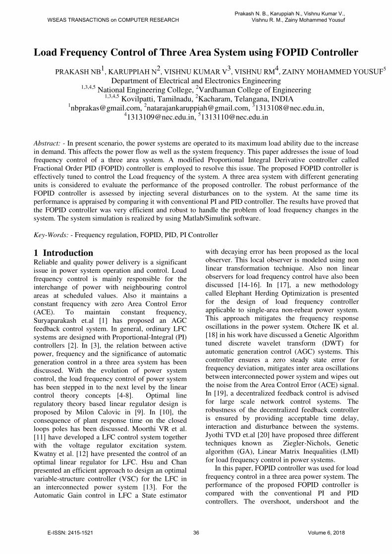
2 Modeling of three area system The three area inter connected power system is
shown in Fig. 1. There are two control loops in
Automatic Gain Control (AGC) namely primary and
secondary control. Primary control deals with local
plant control and secondary control refers to the
minimization of Area Control Error (ACE).
Fig. 1 Load Frequency Control of a three area
system
Change in the tie line power between area 1 and 2
(1)
Change in the tie line power between area 1 and 3
))()((2
311331, SFSFTs
Ptie
(2)
Change in the tie line power between area 2 and 3
))()((2
322332, SFSFTs
Ptie
(3)
where
ijT -Tie line power between ith
and jth
areas
iF - Frequency of ith
area
So the total tie line power change between area 1
and the other two areas is calculated as
31,21,1, tietietie PPP (4)
When the load on the system decreases, the system
frequency rises. Similarly the system frequency
drops when the load on the system increases.
However the frequency deviation has to be
maintained as zero. To keep the load frequency
constant, tie line power flow is to be controlled. It
allows bi directional flow of power by maintaining a
constant frequency. Tie line power flow is helpful in
load frequency control by keeping Area Control
Error as zero. Let the parameters of the three area
system are as given below:
Non Reheat
(Area 1)
M1 (p.u.s) 10
D1 (p.u./Hz) 1
Tch1(s) 0.3
TG1(s) 0.1
R1(Hz/p.u.) 0.05
B1 (p.u./Hz) 21
T1 (p.u./rad) 22.6
Hydraulic (Area 3)
M3 (p.u.s) 6
D3 (p.u./Hz) 1
TG3(s) 0.2
Tr (s) 5
Rt (Hz/p.u.) 0.38
R3 (Hz/p.u.) 0.05
B3 (p.u./Hz) 21
Tw (s) 1
T3 (p.u./rad) 22.6
3 FOPID Controller Podlubny proposed the concept of FOPID
controller. In FOPID the order of derivative and
integral is not integer. This characteristic provides
extra degrees of freedom. This improves the
dynamic response of the system. The formulation of
FOPID controller is given in equation 5.
SK
S
KKSK d
i
p )( (5)
Reheat (Area 2)
M2 (p.u.s) 10
D2 (p.u./Hz) 1
Tch2(s) 0.3
Fhp 0.3
Trh (s) 7
TG2(s) 0.2
R2 (Hz/p.u.) 0.05
B2 (p.u./Hz) 21
T2 (p.u./rad) 22.6
))()((2
211221, SFSFTs
Ptie
WSEAS TRANSACTIONS on COMPUTER RESEARCHPrakash N. B., Karuppiah N., Vishnu Kumar V.,
Vishnu R. M., Zainy Mohammed Yousuf
E-ISSN: 2415-1521 37 Volume 6, 2018
where Kp, KI, and Kd are proportional, integral, and
derivative gain, respectively. Also, k and l are
orders of integral and derivative, respectively. It is
shown that implementing FOPID controller for LFC
improves the power system response in terms of
settling time, overshoot, and undershoot. Moreover,
this controller is robust to changes in power system
parameters.
4 Results and Discussion Load Frequency Control behaviour of a three area
power system is studied using MATLAB
simulation. LFC of a three area system with three
different controllers and their response for an input
disturbance are studied. If the disturbance is given
to any one of the three areas, the power to
compensate the tie-line power change initially
comes from all the three areas and frequency drops
in all the areas and this drop of frequency is sensed
by the speed governors of the three areas. However,
after a few seconds steady state is achieved by
nullifying the frequency deviation using the control
action of the controllers. The frequency deviation
and the settling time post disturbance in area 1 for
PI controller are tabulated in Table 1. The frequency
deviation response of three areas using PI controller
due to disturbance in Area 1 is shown in Fig. 2, Fig.
3 and Fig. 4 respectively.
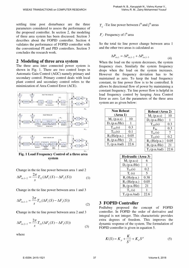
Fig. 2 Frequency deviation of Area 1 due to step
input disturbance in Area 1
Fig. 3 Frequency deviation of Area 2 due
to step input disturbance in Area 1
Fig. 4 Frequency deviation of Area 3 due
to step input disturbance in Area 1
Table 1
Parameter variation of three area system using
PI controller post disturbance in Area 1
Parameters Area 1 Area 2 Area 3
Overshoot (mHz) 16.5 5.8 1
Undershoot (mHz) - -8.4 -15.8
Settling Time (Sec) 38 >40 >40
The step disturbance is applied to area1 and the
frequency deviation due to the step disturbance
using PI controller and its effects on the area 2 and
area 3 are observed. The overshoot, undershoot and
the settling time are observed for areas 1, 2 and 3. It
takes 38 seconds for the oscillations to settle down
in area 1 and in areas 2 and 3 the oscillations takes
more than 40 seconds to settle down. The frequency
deviation and the settling time post disturbance in
area 1 for PID controller are tabulated in Table 2.
The frequency deviation response of three areas
using PID controller due to disturbance in Area 1 is
shown in Fig. 5, Fig. 6 and Fig. 7 respectively.
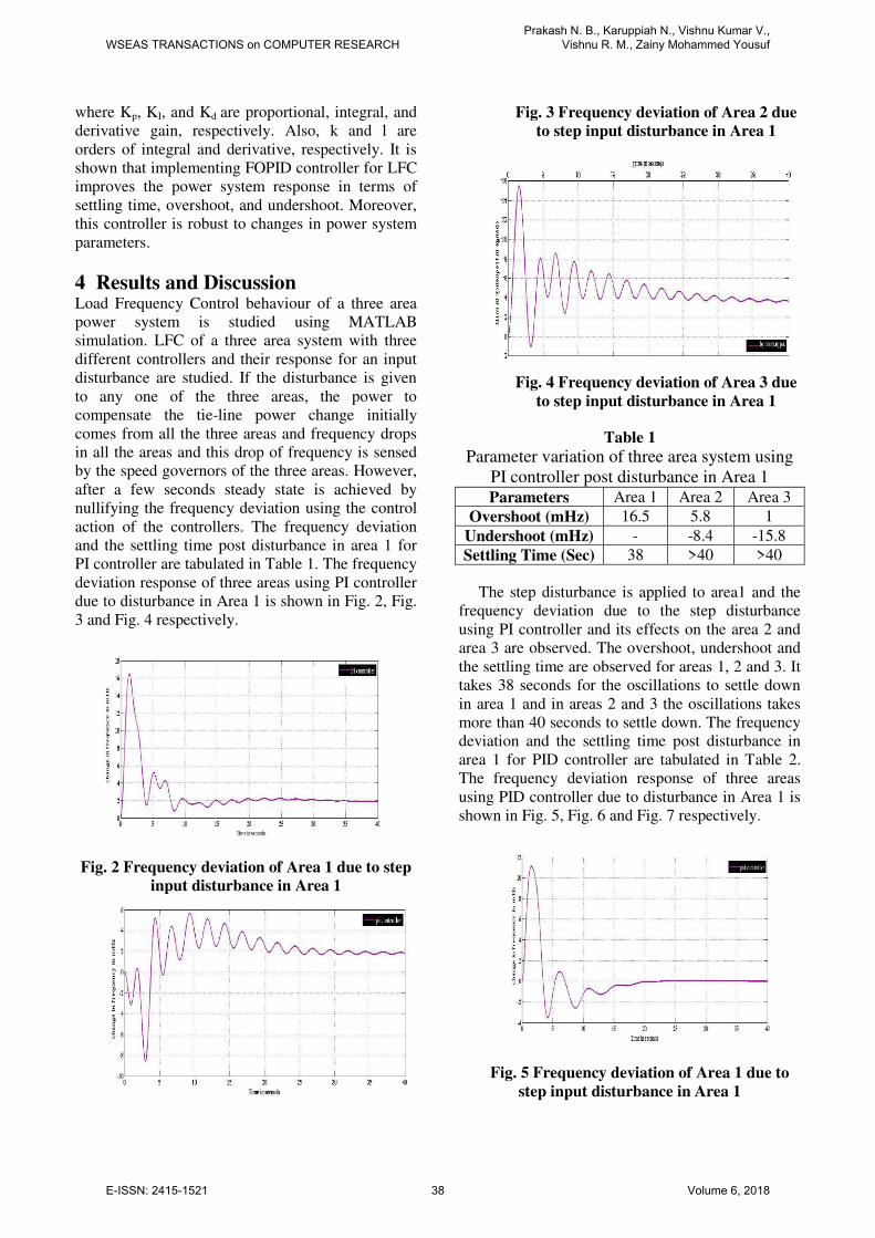
Fig. 5 Frequency deviation of Area 1 due to
step input disturbance in Area 1
WSEAS TRANSACTIONS on COMPUTER RESEARCHPrakash N. B., Karuppiah N., Vishnu Kumar V.,
Vishnu R. M., Zainy Mohammed Yousuf
E-ISSN: 2415-1521 38 Volume 6, 2018
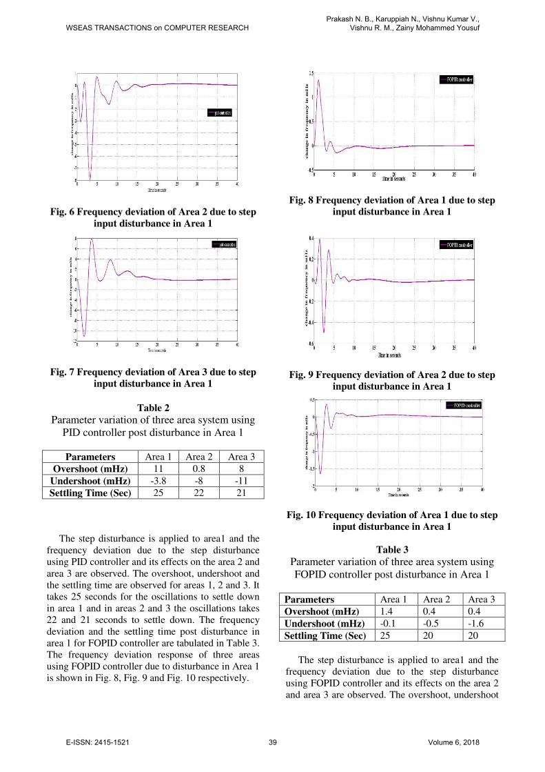
Fig. 6 Frequency deviation of Area 2 due to step
input disturbance in Area 1
Fig. 7 Frequency deviation of Area 3 due to step
input disturbance in Area 1
Table 2
Parameter variation of three area system using
PID controller post disturbance in Area 1
Parameters Area 1 Area 2 Area 3
Overshoot (mHz) 11 0.8 8
Undershoot (mHz) -3.8 -8 -11
Settling Time (Sec) 25 22 21
The step disturbance is applied to area1 and the
frequency deviation due to the step disturbance
using PID controller and its effects on the area 2 and
area 3 are observed. The overshoot, undershoot and
the settling time are observed for areas 1, 2 and 3. It
takes 25 seconds for the oscillations to settle down
in area 1 and in areas 2 and 3 the oscillations takes
22 and 21 seconds to settle down. The frequency
deviation and the settling time post disturbance in
area 1 for FOPID controller are tabulated in Table 3.
The frequency deviation response of three areas
using FOPID controller due to disturbance in Area 1
is shown in Fig. 8, Fig. 9 and Fig. 10 respectively.
Fig. 8 Frequency deviation of Area 1 due to step
input disturbance in Area 1
Fig. 9 Frequency deviation of Area 2 due to step
input disturbance in Area 1
Fig. 10 Frequency deviation of Area 1 due to step
input disturbance in Area 1
Table 3
Parameter variation of three area system using
FOPID controller post disturbance in Area 1
Parameters Area 1 Area 2 Area 3
Overshoot (mHz) 1.4 0.4 0.4
Undershoot (mHz) -0.1 -0.5 -1.6
Settling Time (Sec) 25 20 20
The step disturbance is applied to area1 and the
frequency deviation due to the step disturbance
using FOPID controller and its effects on the area 2
and area 3 are observed. The overshoot, undershoot
WSEAS TRANSACTIONS on COMPUTER RESEARCHPrakash N. B., Karuppiah N., Vishnu Kumar V.,
Vishnu R. M., Zainy Mohammed Yousuf
E-ISSN: 2415-1521 39 Volume 6, 2018
and the settling time are observed for areas 1, 2 and
3. It takes 25 seconds for the oscillations to settle
down in area 1 and in areas 2 and 3 the oscillations
takes 20 seconds to settle down. The performance
comparison between PI, PID and FOPID controllers
is tabulated in Table 4.
Table 4 Parameter variation of three area system using PI,
PID and FOPID controller due to post disturbance in
Area 1
Parameters Area 1
PI PID FOPID
Overshoot (mHz) 16.5 11 1.4
Undershoot (mHz) - -3.8 -0.1
Settling Time (Seconds) 38 25 25
Parameters Area 2
PI PI PI
Overshoot (mHz) 5.8 5.8 5.8
Undershoot (mHz) -8.4 -8.4 -8.4
Settling Time (Seconds) >40 >40 >40
Parameters Area 3
PI PI PI
Overshoot (mHz) 1 1 1
Undershoot (mHz) -15.8 -15.8 -15.8
Settling Time (Seconds) >40 >40 >40
From Table 4 it is observed that the FOPID
controller outperforms the PI and PID controllers.
The magnitude of overshoot is less when FOPID
controller is used for Load Frequency Control in a
three area system. Similarly the settling time post
disturbance is less with FOPID controllers. The
change in area 1, area 2 and area 3 frequencies with
PI, PID and FOPID controllers due to a step
increase in demand of area 1 is shown in Fig. 11,
Fig. 12 and Fig. 13 respectively.
Fig. 11 Change in area 1 frequency for a
step increase in demand of area 1 using
PI, PID and FOPID controllers
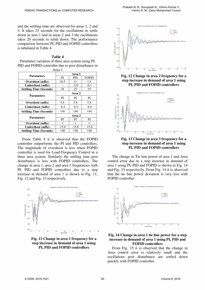
Fig. 12 Change in area 2 frequency for a
step increase in demand of area 1 using
PI, PID and FOPID controllers
Fig. 13 Change in area 3 frequency for a
step increase in demand of area 1 using
PI, PID and FOPID controllers
The change in Tie line power of area 1 and Area
control error due to a step increase in demand of
area 1 using PI, PID and FOPID is shown in Fig. 14
and Fig. 15 respectively. From Fig. 14 it is observed
that the tie line power deviation is very less with
FOPID controller.
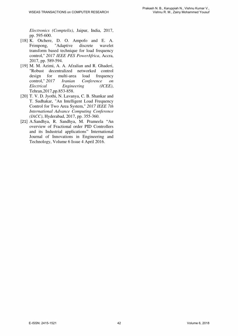
Fig. 14 Change in area 1 tie line power for a step
increase in demand of area 1 using PI, PID and
FOPID controllers
From Fig. 15 it is observed that the change in
Area control error is relatively small and the
oscillations post disturbance are settled down
quickly with FOPID controller.
WSEAS TRANSACTIONS on COMPUTER RESEARCHPrakash N. B., Karuppiah N., Vishnu Kumar V.,
Vishnu R. M., Zainy Mohammed Yousuf
E-ISSN: 2415-1521 40 Volume 6, 2018
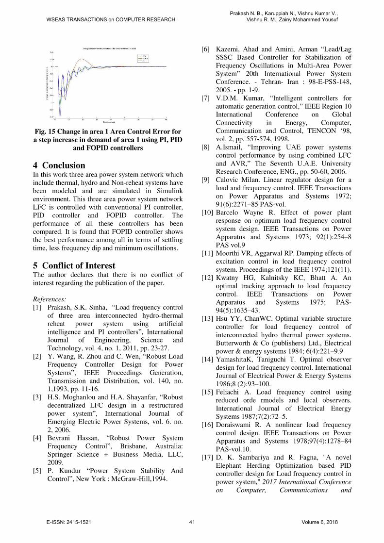
Fig. 15 Change in area 1 Area Control Error for
a step increase in demand of area 1 using PI, PID
and FOPID controllers
4 Conclusion In this work three area power system network which
include thermal, hydro and Non-reheat systems have
been modeled and are simulated in Simulink
environment. This three area power system network
LFC is controlled with conventional PI controller,
PID controller and FOPID controller. The
performance of all these controllers has been
compared. It is found that FOPID controller shows
the best performance among all in terms of settling
time, less frequency dip and minimum oscillations.
5 Conflict of Interest The author declares that there is no conflict of
interest regarding the publication of the paper.
References:
[1] Prakash, S.K. Sinha, “Load frequency control
of three area interconnected hydro-thermal
reheat power system using artificial
intelligence and PI controllers”, International
Journal of Engineering, Science and
Technology, vol. 4, no. 1, 2011, pp. 23-27.
[2] Y. Wang, R. Zhou and C. Wen, “Robust Load
Frequency Controller Design for Power
Systems”, IEEE Proceedings Generation,
Transmission and Distribution, vol. 140, no.
1,1993, pp. 11-16.
[3] H.S. Moghanlou and H.A. Shayanfar, “Robust
decentralized LFC design in a restructured
power system”, International Journal of
Emerging Electric Power Systems, vol. 6. no.
2, 2006.
[4] Bevrani Hassan, “Robust Power System
Frequency Control”, Brisbane, Australia:
Springer Science + Business Media, LLC,
2009.
[5] P. Kundur “Power System Stability And
Control”, New York : McGraw-Hill,1994.
[6] Kazemi, Ahad and Amini, Arman “Lead/Lag
SSSC Based Controller for Stabilization of
Frequency Oscillations in Multi-Area Power
System” 20th International Power System
Conference. - Tehran- Iran : 98-E-PSS-148,
2005. - pp. 1-9.
[7] V.D.M. Kumar, “Intelligent controllers for
automatic generation control,” IEEE Region 10
International Conference on Global
Connectivity in Energy, Computer,
Communication and Control, TENCON ‘98,
vol. 2, pp. 557-574, 1998.
[8] A.Ismail, “Improving UAE power systems
control performance by using combined LFC
and AVR,” The Seventh U.A.E. University
Research Conference, ENG., pp. 50-60, 2006.
[9] Calovic Milan. Linear regulator design for a
load and frequency control. IEEE Transactions
on Power Apparatus and Systems 1972;
91(6):2271–85 PAS-vol.
[10] Barcelo Wayne R. Effect of power plant
response on optimum load frequency control
system design. IEEE Transactions on Power
Apparatus and Systems 1973; 92(1):254–8
PAS vol.9
[11] Moorthi VR, Aggarwal RP. Damping effects of
excitation control in load frequency control
system. Proceedings of the IEEE 1974;121(11).
[12] Kwatny HG, Kalnitsky KC, Bhatt A. An
optimal tracking approach to load frequency
control. IEEE Transactions on Power
Apparatus and Systems 1975; PAS-
94(5):1635–43.
[13] Hsu YY, ChanWC. Optimal variable structure
controller for load frequency control of
interconnected hydro thermal power systems.
Butterworth & Co (publishers) Ltd., Electrical
power & energy systems 1984; 6(4):221–9.9
[14] YamashitaK, Taniguchi T. Optimal observer
design for load frequency control. International
Journal of Electrical Power & Energy Systems
1986;8 (2):93–100.
[15] Feliachi A. Load frequency control using
reduced orde rmodels and local observers.
International Journal of Electrical Energy
Systems 1987;7(2):72–5.
[16] Doraiswami R. A nonlinear load frequency
control design. IEEE Transactions on Power
Apparatus and Systems 1978;97(4):1278–84
PAS-vol.10.
[17] D. K. Sambariya and R. Fagna, "A novel
Elephant Herding Optimization based PID
controller design for Load frequency control in
power system," 2017 International Conference
on Computer, Communications and
WSEAS TRANSACTIONS on COMPUTER RESEARCHPrakash N. B., Karuppiah N., Vishnu Kumar V.,
Vishnu R. M., Zainy Mohammed Yousuf
E-ISSN: 2415-1521 41 Volume 6, 2018
Electronics (Comptelix), Jaipur, India, 2017,
pp. 595-600.
[18] K. Otchere, D. O. Ampofo and E. A.
Frimpong, "Adaptive discrete wavelet
transform based technique for load frequency
control," 2017 IEEE PES PowerAfrica, Accra,
2017, pp. 589-594.
[19] M. M. Azimi, A. A. Afzalian and R. Ghaderi,
"Robust decentralized networked control
design for multi-area load frequency
control," 2017 Iranian Conference on
Electrical Engineering (ICEE),
Tehran,2017,pp.853-858.
[20] T. V. D. Jyothi, N. Lavanya, C. B. Shankar and
T. Sudhakar, "An Intelligent Load Frequency
Control for Two Area System," 2017 IEEE 7th
International Advance Computing Conference
(IACC), Hyderabad, 2017, pp. 355-360.
[21] A.Sandhya, R. Sandhya, M. Prameela “An
overview of Fractional order PID Controllers
and its Industrial applications” International
Journal of Innovations in Engineering and
Technology, Volume 6 Issue 4 April 2016.
WSEAS TRANSACTIONS on COMPUTER RESEARCHPrakash N. B., Karuppiah N., Vishnu Kumar V.,
Vishnu R. M., Zainy Mohammed Yousuf
E-ISSN: 2415-1521 42 Volume 6, 2018