liquid fluids atomization
TRANSCRIPT
COMBUSTION AND FUELS
ATOMIZATION OFLIQUID FUELS
COMBUSTION AND FUELS
THE PRINCIPLE OF LIQIUDS ATOMIZATION
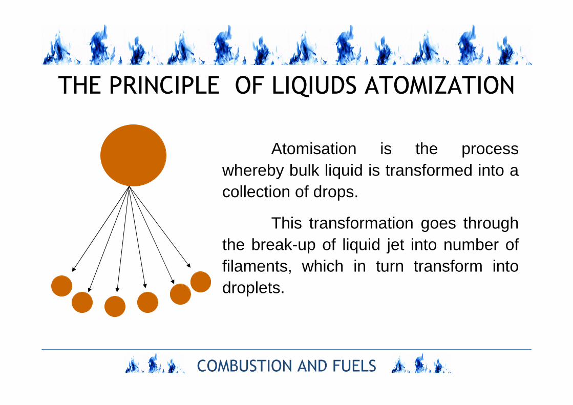
Atomisation is the process whereby bulk liquid is transformed into a collection of drops.
This transformation goes through the break-up of liquid jet into number of filaments, which in turn transform into droplets.
COMBUSTION AND FUELS
MECHANISMS OF LIQIUDS ATOMIZATION
Three mechanisms:
Disintegration of a liquid jet into a number of filaments,
and then into small droplets, requires the surface tension forces of
liquid to be overcome. It may happen on the three ways:
– by surface tension between moving liquid jet and steady air
which destabilise the jet and causes its disintegration into
filaments,
– by centrifugal forces of swirled liquid jet,
– outer mechanical and electrostatic forces and by supersonic
acoustic.
COMBUSTION AND FUELS
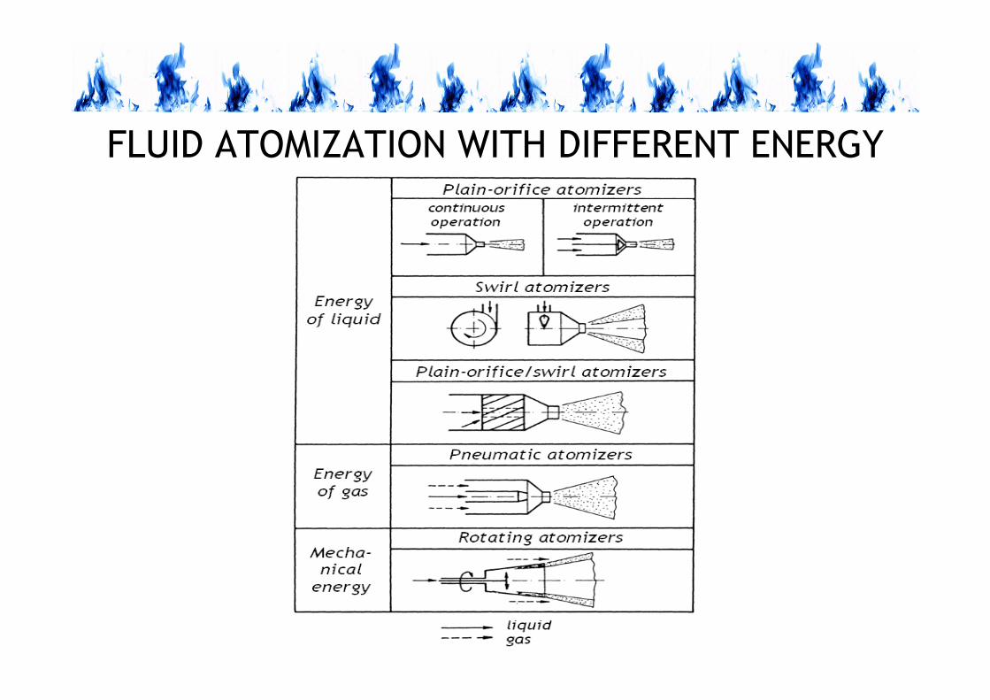
FLUID ATOMIZATION WITH DIFFERENT ENERGY
COMBUSTION AND FUELS
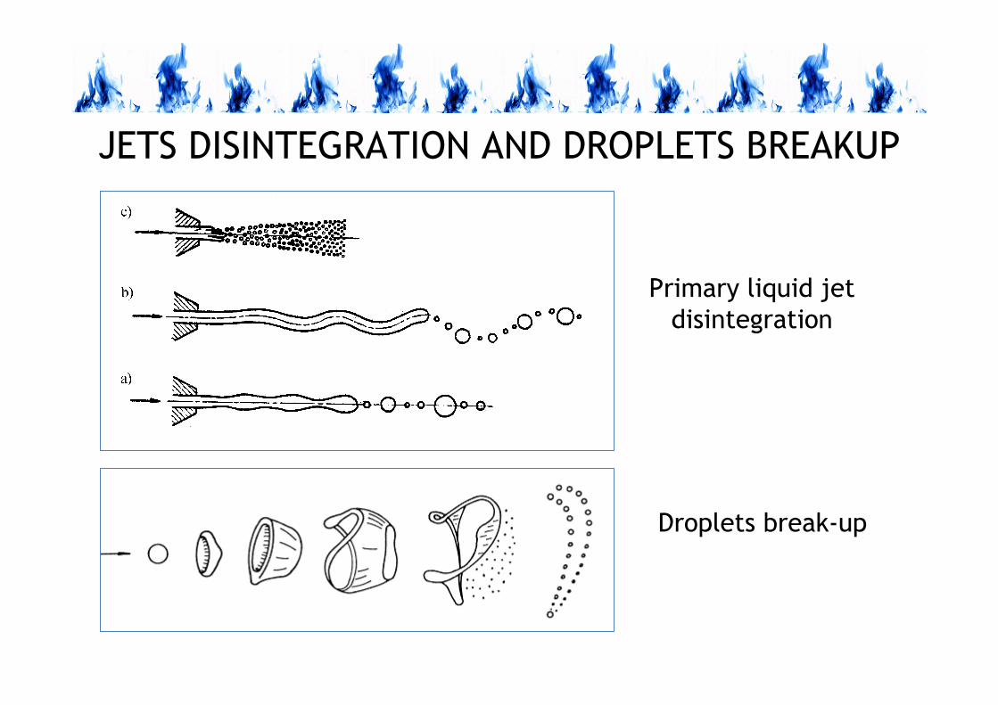
JETS DISINTEGRATION AND DROPLETS BREAKUP
Droplets break-up
Primary liquid jet
disintegration
COMBUSTION AND FUELS
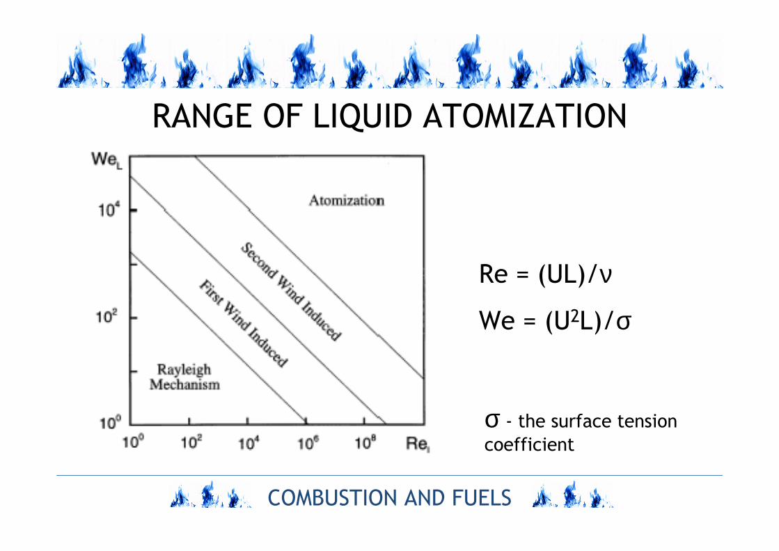
RANGE OF LIQUID ATOMIZATION
Re = (UL)/ν
We = (U2L)/σ
σ - the surface tension
coefficient
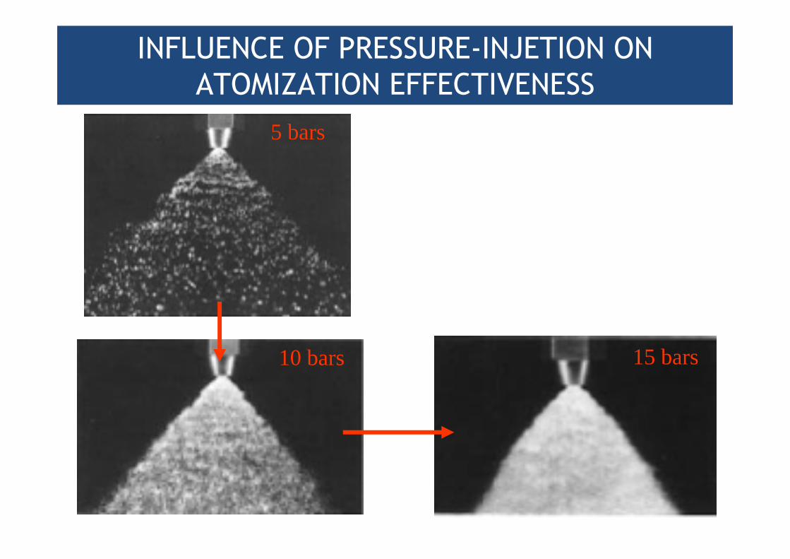
INFLUENCE OF PRESSURE-INJETION ON
ATOMIZATION EFFECTIVENESS
5 bars
10 bars 15 bars
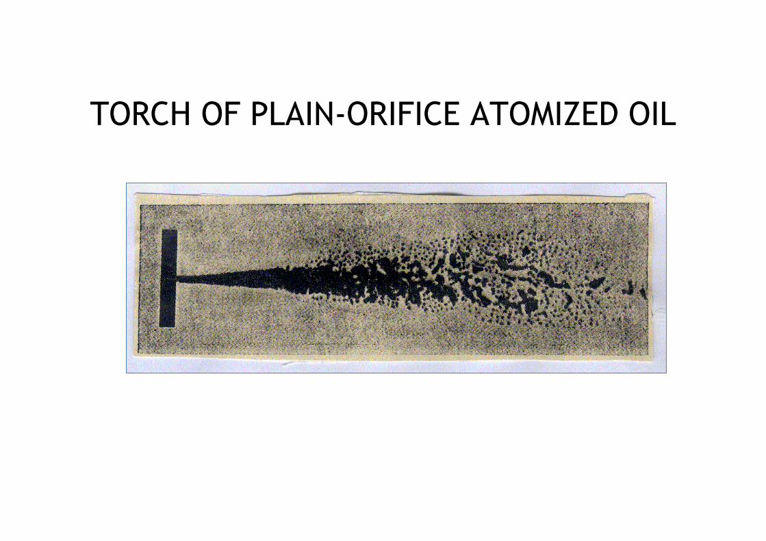
TORCH OF PLAIN-ORIFICE ATOMIZED OIL
COMBUSTION AND FUELS
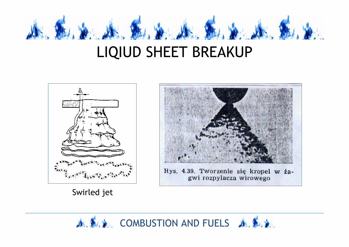
LIQIUD SHEET BREAKUP
Swirled jet
COMBUSTION AND FUELS
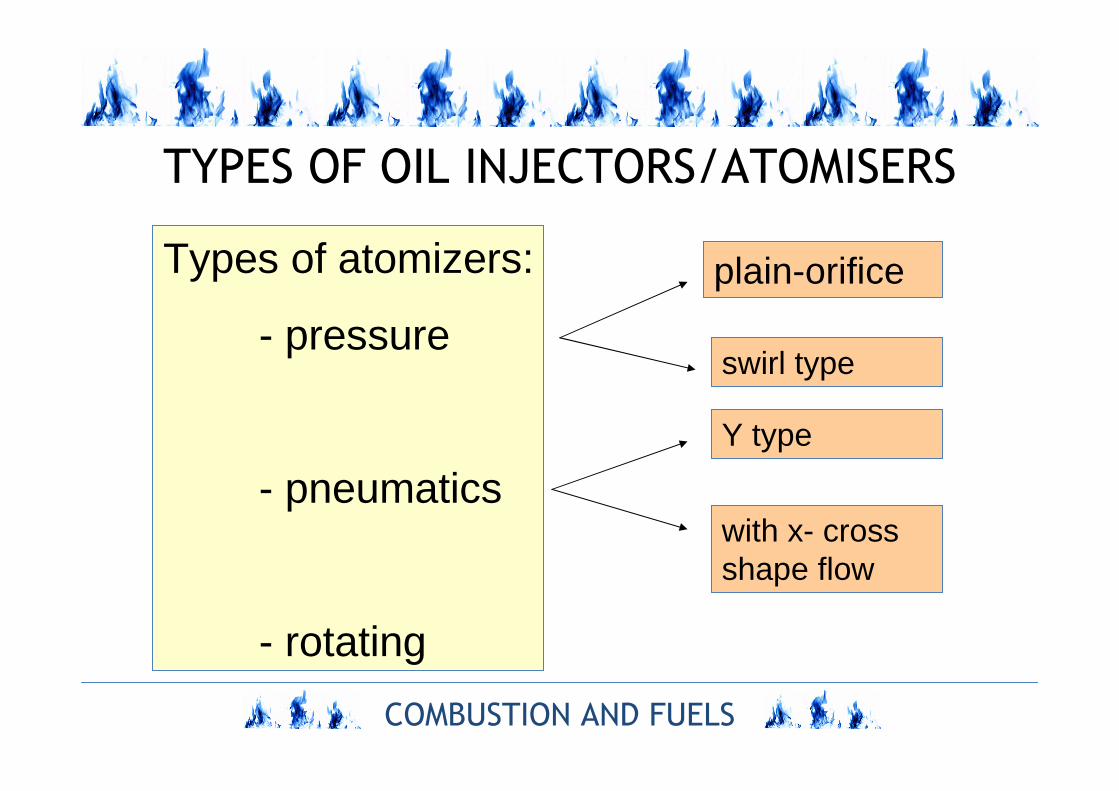
TYPES OF OIL INJECTORS/ATOMISERS
Types of atomizers:
- pressure
- pneumatics
- rotating
plain-orifice
swirl type
Y type
with x- cross shape flow
COMBUSTION AND FUELS
PRESSURE INJECTORS
COMBUSTION AND FUELS
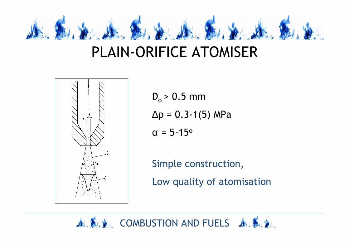
PLAIN-ORIFICE ATOMISER
Do > 0.5 mm
∆p = 0.3-1(5) MPa
α = 5-15o
Simple construction,
Low quality of atomisation
COMBUSTION AND FUELS
SWIRL ATOMIZERS
COMBUSTION AND FUELS
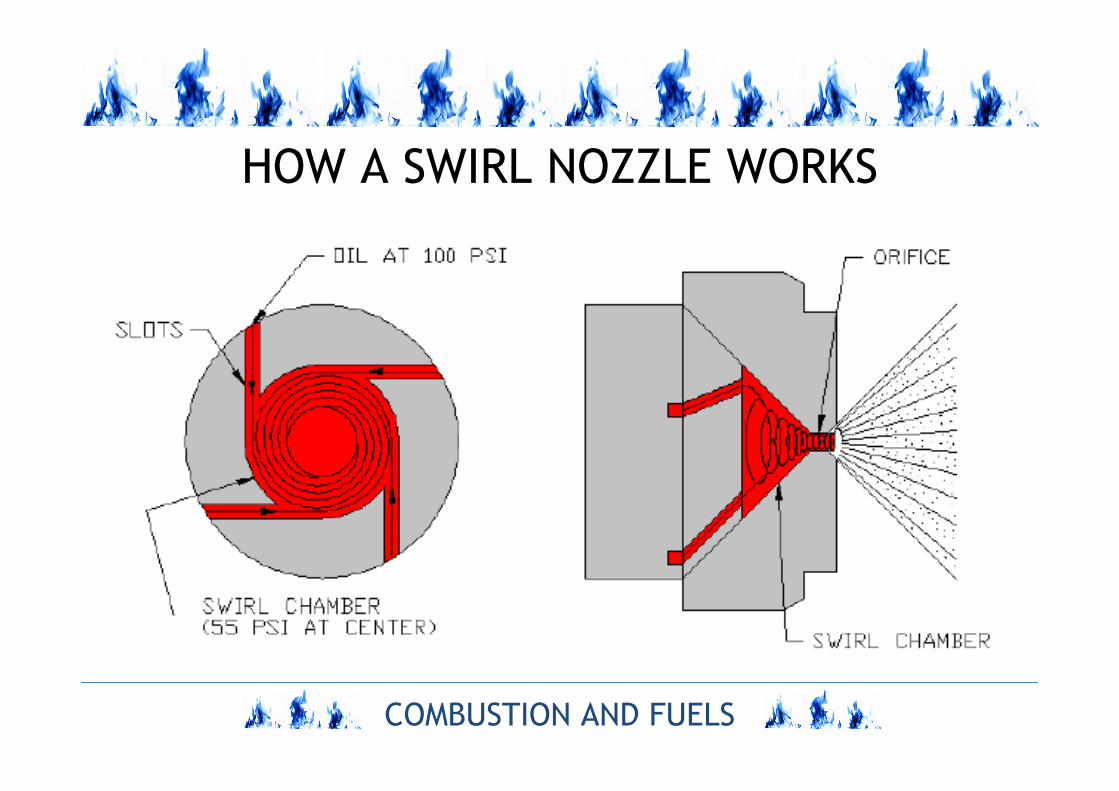
HOW A SWIRL NOZZLE WORKS
COMBUSTION AND FUELS
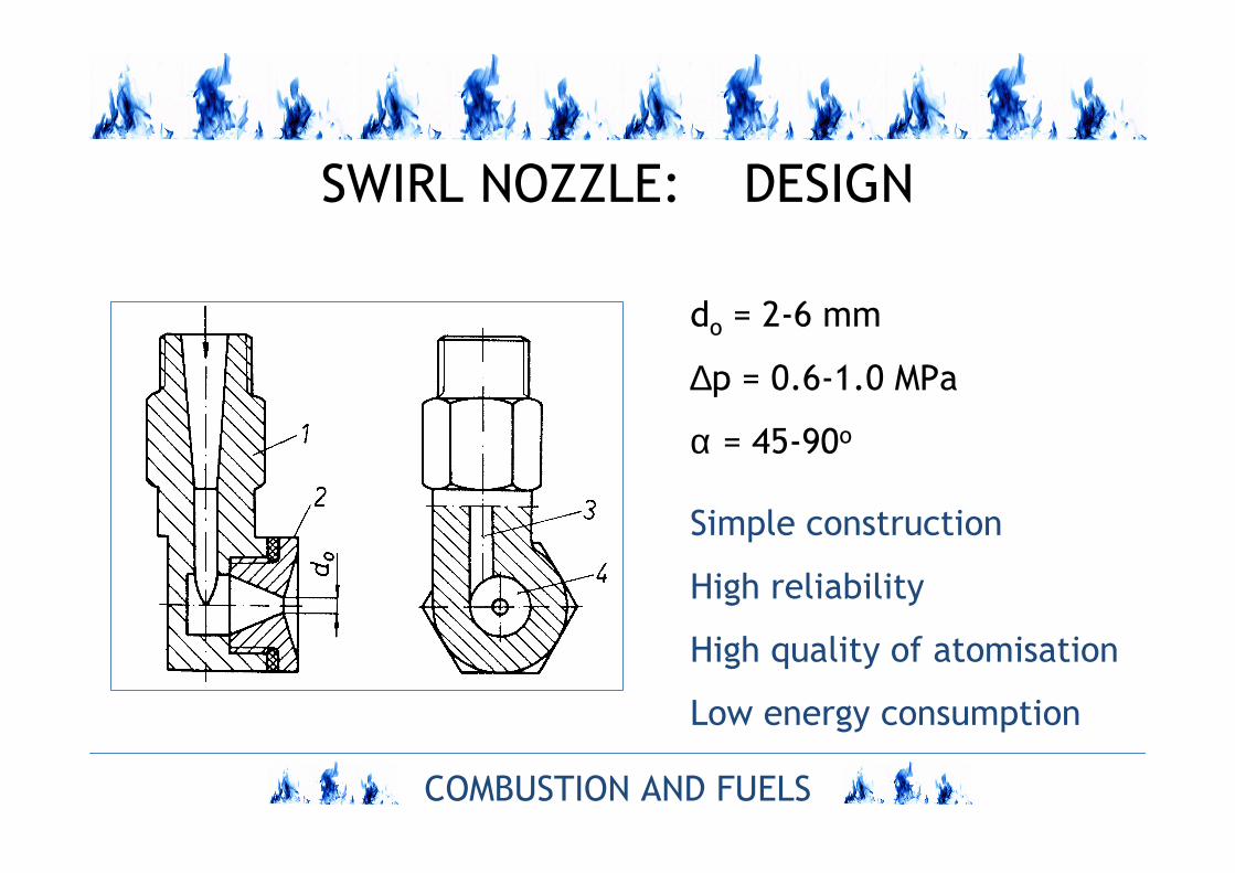
SWIRL NOZZLE: DESIGN
do = 2-6 mm
∆p = 0.6-1.0 MPa
α = 45-90o
Simple construction
High reliability
High quality of atomisation
Low energy consumption
COMBUSTION AND FUELS
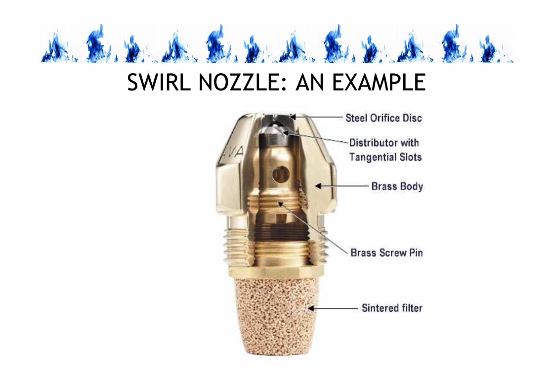
SWIRL NOZZLE: AN EXAMPLE
COMBUSTION AND FUELS
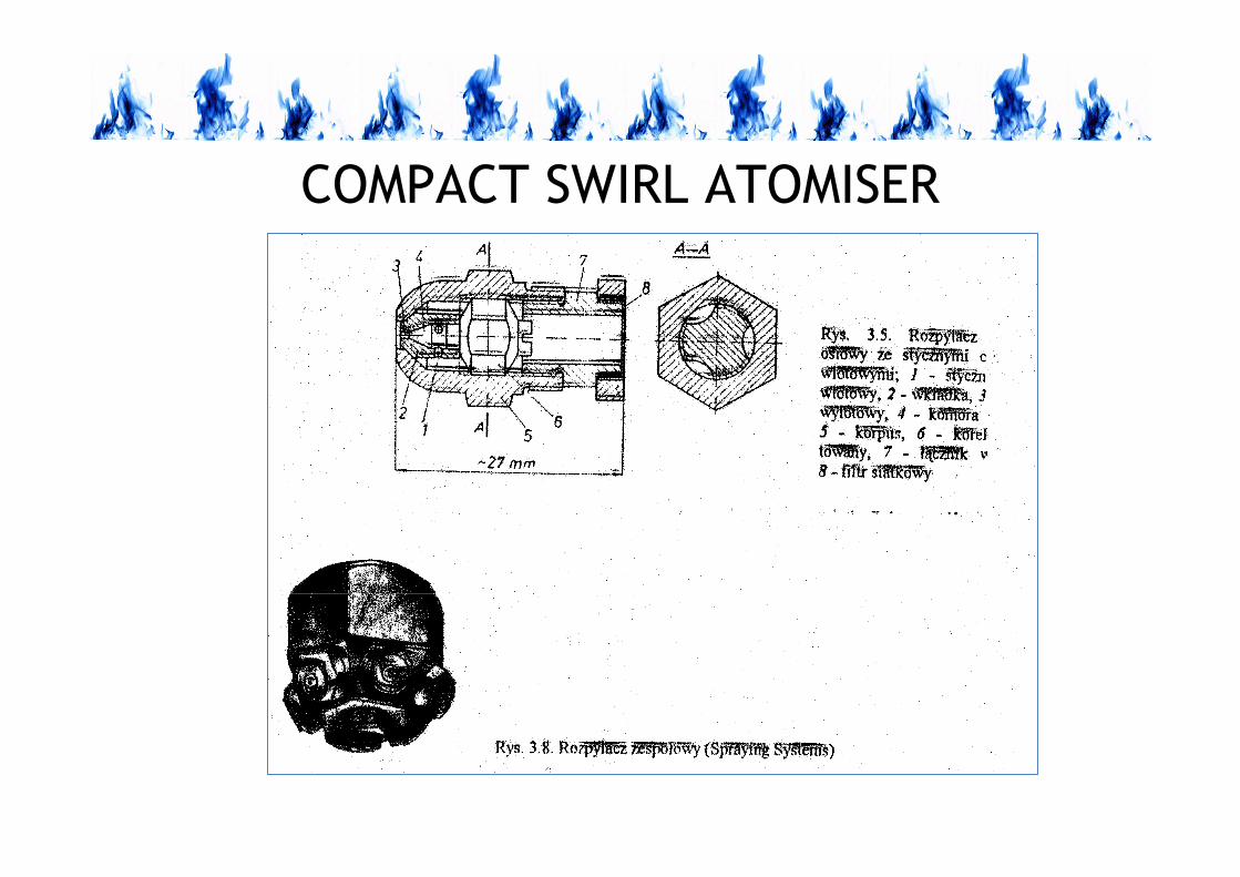
COMPACT SWIRL ATOMISER
COMBUSTION AND FUELS
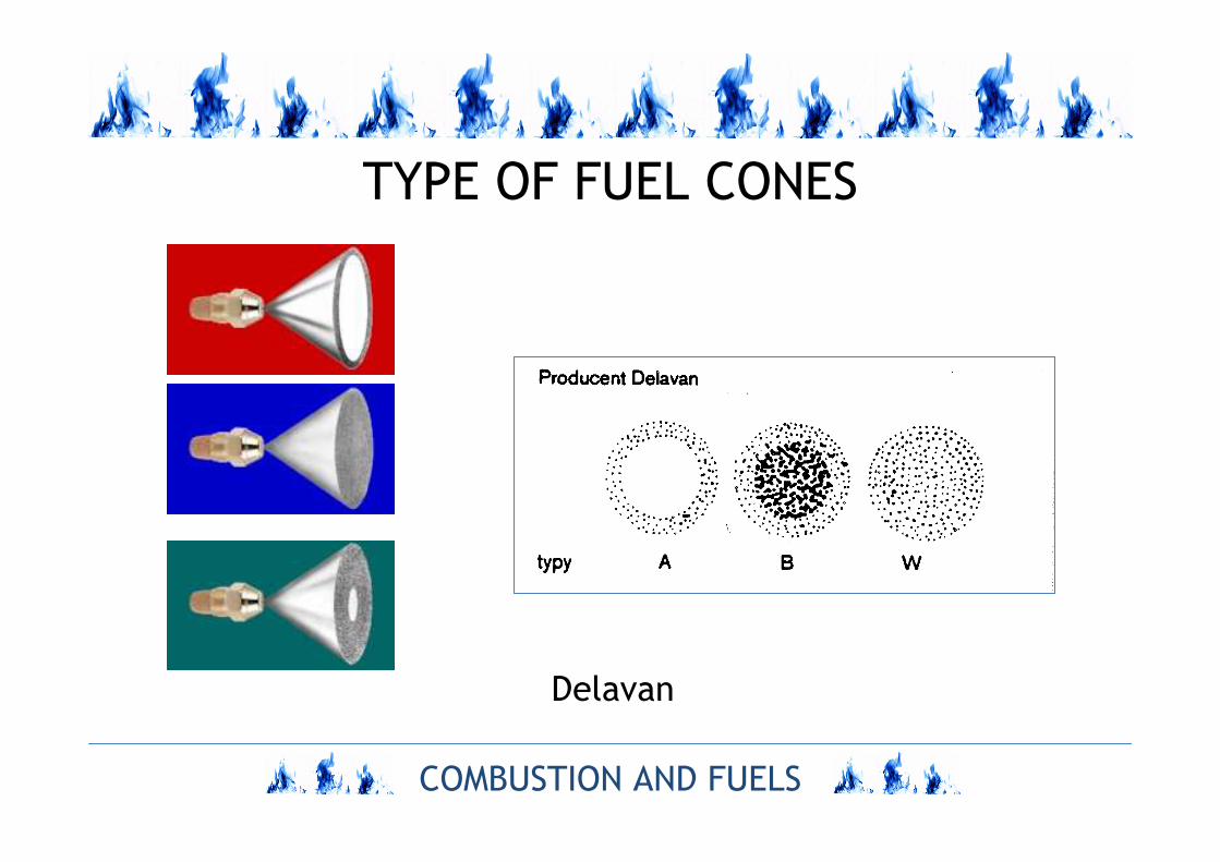
TYPE OF FUEL CONES
Delavan
COMBUSTION AND FUELS
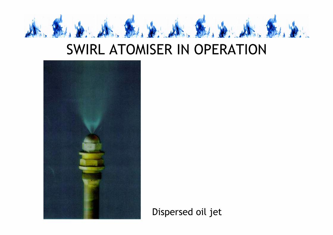
SWIRL ATOMISER IN OPERATION
Dispersed oil jet
COMBUSTION AND FUELS
PNEUMATIC ATOMISERS
COMBUSTION AND FUELS
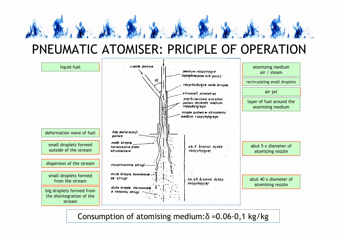
PNEUMATIC ATOMISER: PRICIPLE OF OPERATION
Consumption of atomising medium:δ =0.06-0,1 kg/kg
atomizing medium
air / steam
recirculating small droplets
air jet
layer of fuel around the
atomizing medium
abut 5 x diameter of
atomizing nozzle
abut 40 x diameter of
atomizing nozzle
liquid fuel
small droplets formed
outside of the stream
dispersion of the stream
small droplets formed
from the stream
big droplets formed from
the disintegration of the
stream
deformation wave of fuel
COMBUSTION AND FUELS
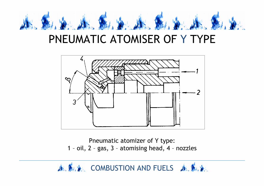
PNEUMATIC ATOMISER OF Y TYPE
Pneumatic atomizer of Y type:
1 – oil, 2 – gas, 3 – atomising head, 4 – nozzles
COMBUSTION AND FUELS
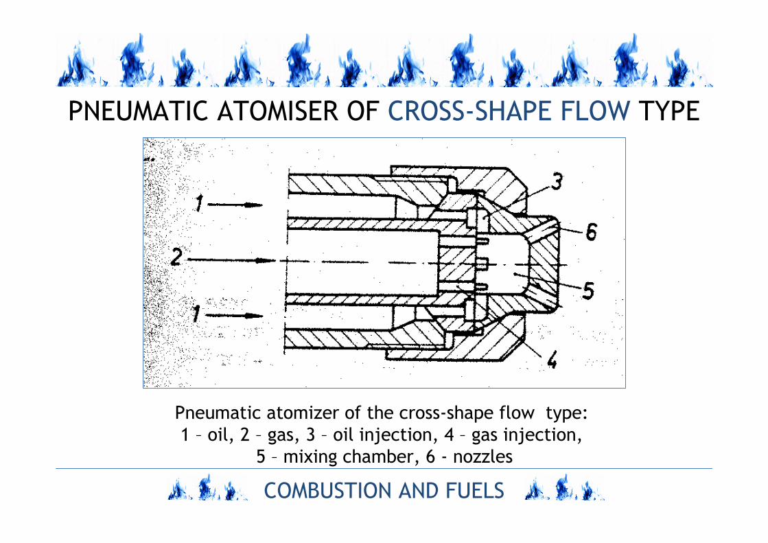
PNEUMATIC ATOMISER OF CROSS-SHAPE FLOW TYPE
Pneumatic atomizer of the cross-shape flow type:
1 – oil, 2 – gas, 3 – oil injection, 4 – gas injection,
5 – mixing chamber, 6 - nozzles
COMBUSTION AND FUELS
ROTATING ATOMISERS
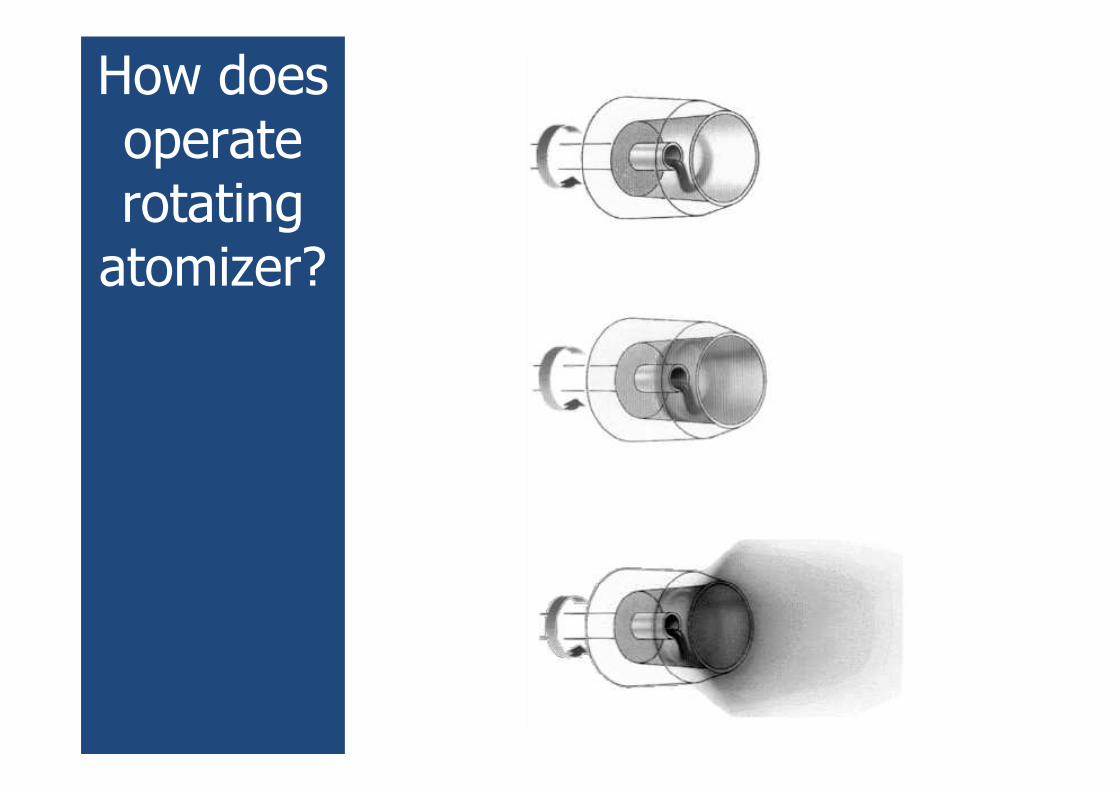
How doesoperaterotatingatomizer?
COMBUSTION AND FUELS
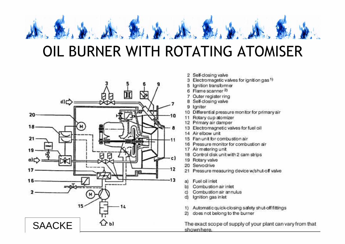
OIL BURNER WITH ROTATING ATOMISER
SAACKE
COMBUSTION AND FUELS
CONTROL OF OIL FLOW RATE
COMBUSTION AND FUELS
ATOMISATION PRESSURE VARIATION
1. The simplest way for oil
output/consumption control is variation of
pressure of atomisation.
2. Disadvantage of this method of output
control is loss of atomisation quality due to
reduction of atomisation pressure.
Rate of oil output ∼∼∼∼ (∆∆∆∆p)0.5
COMBUSTION AND FUELS
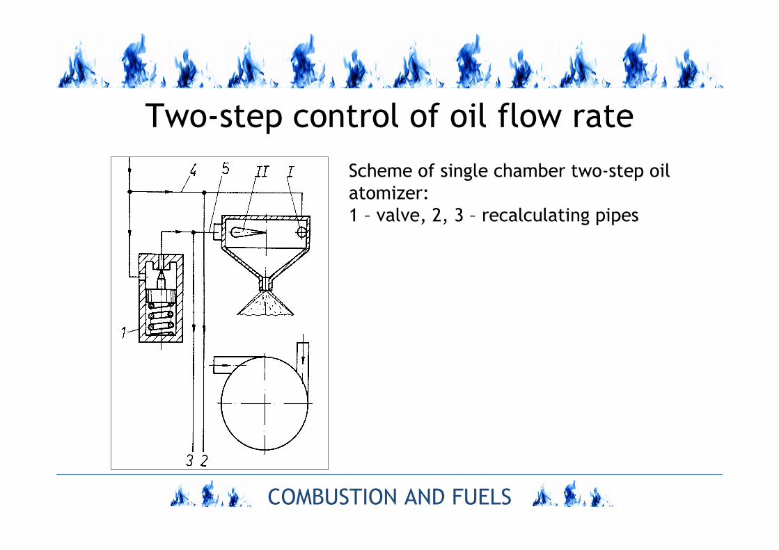
Two-step control of oil flow rate
Scheme of single chamber two-step oil
atomizer:
1 – valve, 2, 3 – recalculating pipes
COMBUSTION AND FUELS
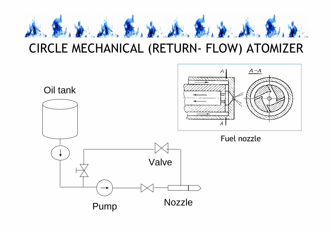
CIRCLE MECHANICAL (RETURN- FLOW) ATOMIZER
Fuel nozzle
Oil tank
NozzlePump
Valve
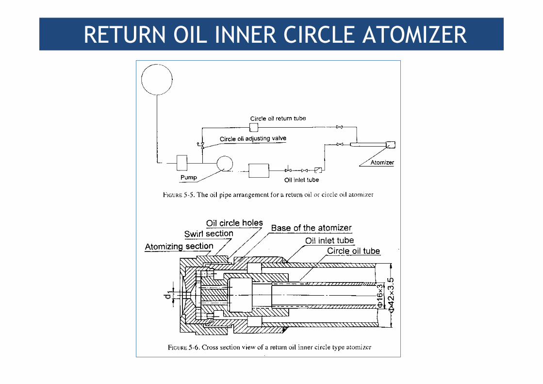
RETURN OIL INNER CIRCLE ATOMIZER
COMBUSTION AND FUELS
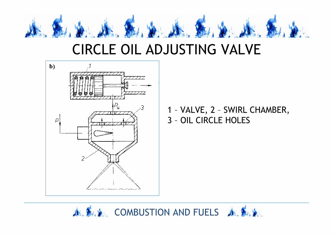
CIRCLE OIL ADJUSTING VALVE
1 – VALVE, 2 – SWIRL CHAMBER,
3 – OIL CIRCLE HOLES
COMBUSTION AND FUELS
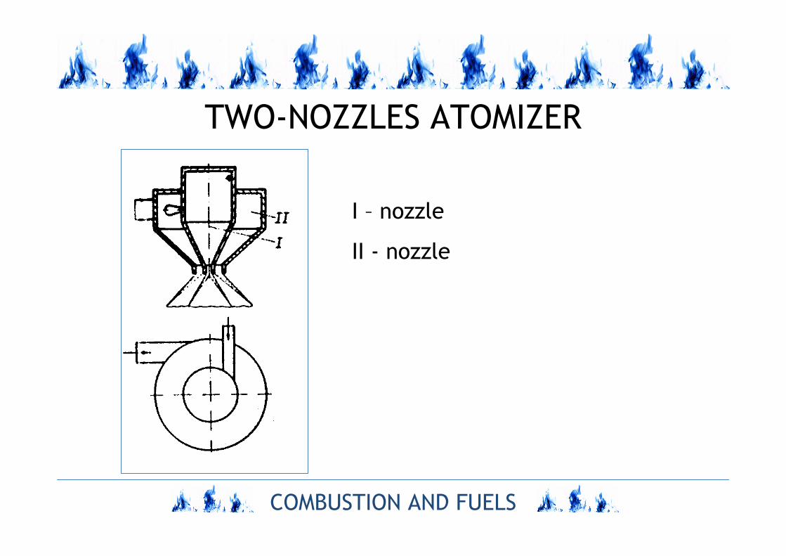
TWO-NOZZLES ATOMIZER
I – nozzle
II - nozzle
COMBUSTION AND FUELS
QUALITY OF ATOMISATION
COMBUSTION AND FUELS
PARAMETERS OF ATOMIZATION
– output, kg/s
– angle of dispersion, deg
– droplets distribution,
– mean diameter of dispersion, m.
COMBUSTION AND FUELS
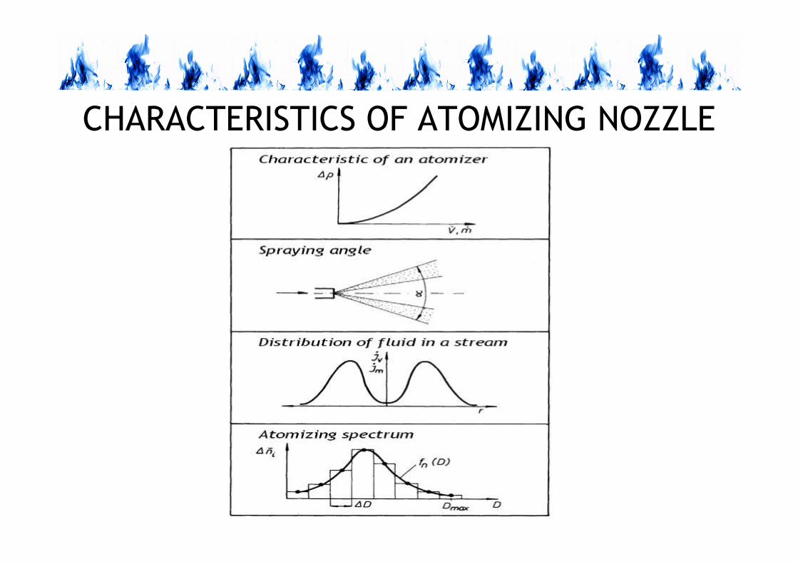
CHARACTERISTICS OF ATOMIZING NOZZLE
COMBUSTION AND FUELS
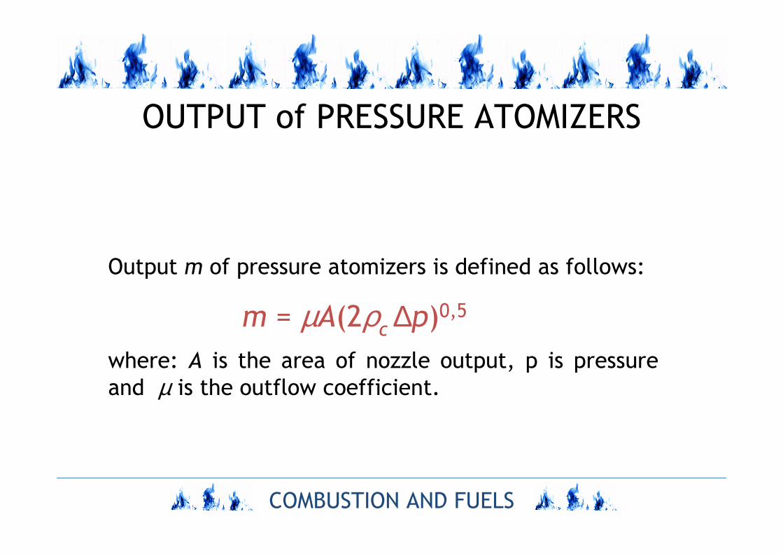
OUTPUT of PRESSURE ATOMIZERS
Output m of pressure atomizers is defined as follows:
m = µA(2ρc ∆p)0,5
where: A is the area of nozzle output, p is pressure
and µ is the outflow coefficient.
COMBUSTION AND FUELS
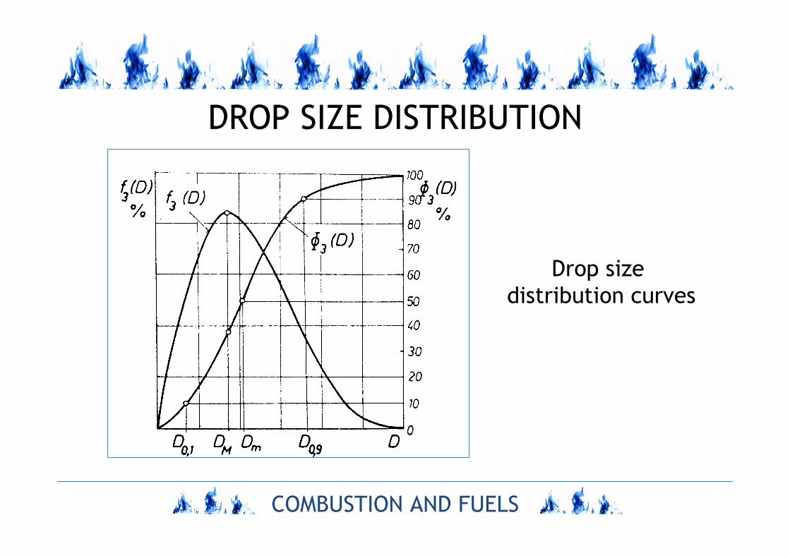
DROP SIZE DISTRIBUTION
Drop size
distribution curves
COMBUSTION AND FUELS
CHARACTERISTIC OF DROPLETS SIZE
Mean drop size:mean drop size
SRK = [(ΣnD3/ΣnD)]0,5,
mean drop size of Sauter
SMD = Σ nD3/Σ nD2.