liquid distributors - koch-glitsch library/plastic_packing_liquid... · liquid distribution liquid...
TRANSCRIPT
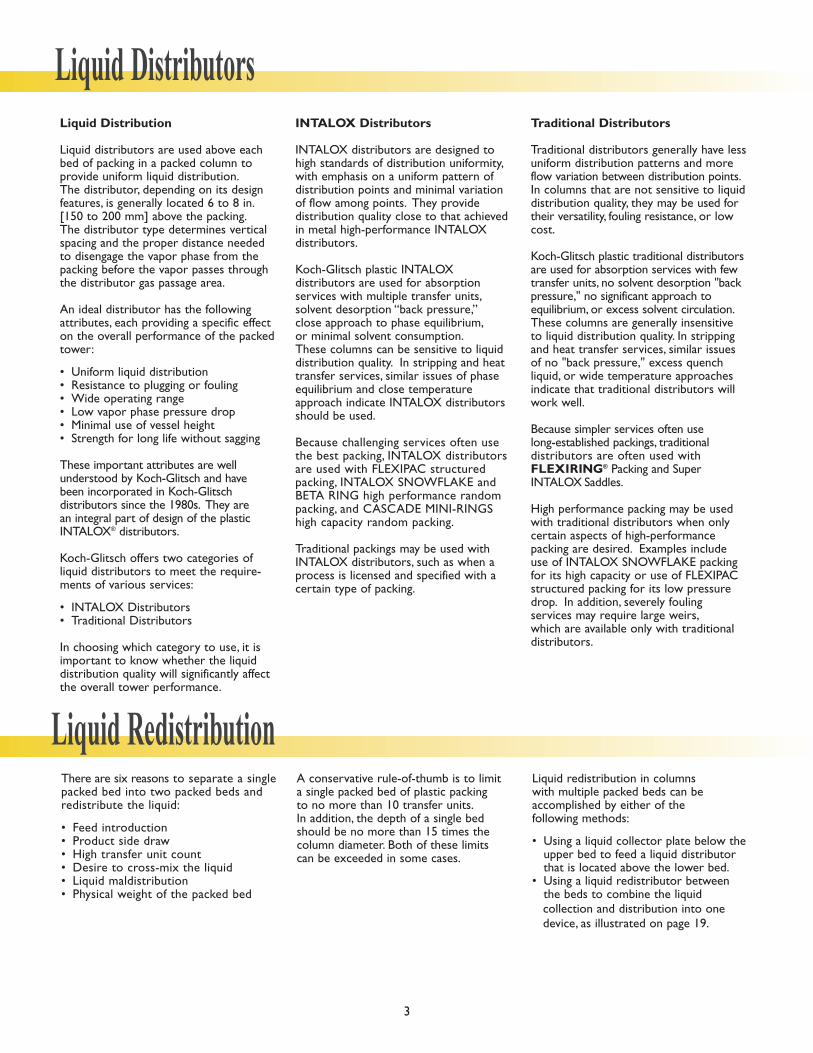
Liquid Distribution
Liquid distributors are used above eachbed of packing in a packed column toprovide uniform liquid distribution.The distributor, depending on its design features, is generally located 6 to 8 in.[150 to 200 mm] above the packing.The distributor type determines verticalspacing and the proper distance neededto disengage the vapor phase from thepacking before the vapor passes throughthe distributor gas passage area.
An ideal distributor has the followingattributes, each providing a specific effecton the overall performance of the packedtower:
• Uniform liquid distribution• Resistance to plugging or fouling• Wide operating range• Low vapor phase pressure drop• Minimal use of vessel height• Strength for long life without sagging
These important attributes are well understood by Koch-Glitsch and have been incorporated in Koch-Glitsch distributors since the 1980s. They are an integral part of design of the plasticINTALOX® distributors.
Koch-Glitsch offers two categories of liquid distributors to meet the require-ments of various services:
• INTALOX Distributors• Traditional Distributors
In choosing which category to use, it isimportant to know whether the liquiddistribution quality will significantly affectthe overall tower performance.
INTALOX Distributors
INTALOX distributors are designed tohigh standards of distribution uniformity,with emphasis on a uniform pattern ofdistribution points and minimal variationof flow among points. They provide distribution quality close to that achievedin metal high-performance INTALOXdistributors.
Koch-Glitsch plastic INTALOXdistributors are used for absorption services with multiple transfer units,solvent desorption “back pressure,” close approach to phase equilibrium,or minimal solvent consumption.These columns can be sensitive to liquiddistribution quality. In stripping and heattransfer services, similar issues of phaseequilibrium and close temperatureapproach indicate INTALOX distributorsshould be used.
Because challenging services often usethe best packing, INTALOX distributorsare used with FLEXIPAC structuredpacking, INTALOX SNOWFLAKE andBETA RING high performance randompacking, and CASCADE MINI-RINGShigh capacity random packing.
Traditional packings may be used withINTALOX distributors, such as when aprocess is licensed and specified with acertain type of packing.
Traditional Distributors
Traditional distributors generally have lessuniform distribution patterns and moreflow variation between distribution points.In columns that are not sensitive to liquiddistribution quality, they may be used fortheir versatility, fouling resistance, or lowcost.
Koch-Glitsch plastic traditional distributorsare used for absorption services with fewtransfer units, no solvent desorption "backpressure," no significant approach to equilibrium, or excess solvent circulation.These columns are generally insensitiveto liquid distribution quality. In strippingand heat transfer services, similar issuesof no "back pressure," excess quench liquid, or wide temperature approachesindicate that traditional distributors willwork well.
Because simpler services often use long-established packings, traditional distributors are often used withFLEXIRING® Packing and Super INTALOX Saddles.
High performance packing may be usedwith traditional distributors when onlycertain aspects of high-performance packing are desired. Examples includeuse of INTALOX SNOWFLAKE packingfor its high capacity or use of FLEXIPACstructured packing for its low pressuredrop. In addition, severely fouling services may require large weirs,which are available only with traditionaldistributors.
There are six reasons to separate a singlepacked bed into two packed beds andredistribute the liquid:
• Feed introduction• Product side draw• High transfer unit count • Desire to cross-mix the liquid• Liquid maldistribution• Physical weight of the packed bed
A conservative rule-of-thumb is to limit a single packed bed of plastic packing to no more than 10 transfer units.In addition, the depth of a single bedshould be no more than 15 times the column diameter. Both of these limits can be exceeded in some cases.
Liquid redistribution in columns with multiple packed beds can be accomplished by either of the following methods:
• Using a liquid collector plate below theupper bed to feed a liquid distributor that is located above the lower bed.
• Using a liquid redistributor between the beds to combine the liquid collection and distribution into one device, as illustrated on page 19.
3
Liquid Distributors
Liquid Redistribution

Distribution Point Density
The density of the distribution points can affect the efficiency of the top of apacked bed. For example, high point densities can make the distributor moreprone to fouling because of smaller orifices. However, with the commonlyused random and structured packings,the effect of point density is relativelyminor. The difference between 5.5 and14.5 points/ft2 [60 to 155 pts/m2] has aslight effect on the packing Height of aTransfer Unit (HTU).
Point density is not the key to liquid distribution quality.
Cross Flow Capacity
At high liquid rate, the cross flow capability of a distributor and its pre-distribution system are important.Gravity-fed distributors are dependenton liquid level to determine flow;therefore, it is important to balance the liquid properly to provide uniformpoint-to-point flow. Pre-distribution isachieved by feed pipes and partingboxes.The pre-distribution system mustproperly meter liquid to one or moreappropriate points on the distributorwithout inducing excessive horizontalvelocity, gradients in liquid head,or turbulence.The design of the pre-distribution system becomesincreasingly complex as the specific liquid rate and the column diameterincreases.
Fouling
For a distributor to perform correctly,the metering device must not becomefouled. There are several sources of fouling materials: polymerization,non-soluble deposits, scale, constructiondebris, sediment, and so forth. Precautionsshould be taken to keep fouling materialsout of the column, because externalstrainers and filters are much easier to clean than distributors. If it is notpossible to eliminate all external fouling sources, or if the source of the fouling material is within the column itself, then the distributorshould be considered for its foulingresistance.
The order of fouling resistance of various metering devices on liquid distributors, starting with the most resistant is:
• V-notch weir• Spray distributor• Slotted weir• Elevated orifice• Bottom orifice
Orifice Size
In gravity-fed distributors, the orifice sizedepends on the distribution point density,the specific liquid rate and height of theliquid. For a single-level orifice with anoperating range of 60 to 120% of thedesign flow, the approximate orifice sizeis shown in the chart below.
Operating Range
A distributor performs best at its designliquid flow rate. As the rate decreasesand the liquid head drops, levelness of the distributor and hydraulic gradients on the distributor become a larger percentage of the operating liquid head. At some turndown rate, the point-to-point flow variation will fall outside of acceptable limits.Plastic INTALOX distributors aredesigned for a maximum flow variation,defined as the coefficient of variation(Cv) of no more than 8% at design ratesand no more than 15% at turndownrates. Special designs are available formany INTALOX distributors that willresult in even lower flow variation.Turndown ranges for various distributormodels are given in the description ofeach distributor.
Koch-Glitsch traditional distributorsallow greater flow variations thanINTALOX distributors and typically arerated for a broader range of operation.For high turndown requirements, multipleorifice levels or slotted weirs may beused with some INTALOX distributordesigns as well as traditional distributorstyles. When these metering styles areused, the flow variation will be higherthrough part of the operating range thanwith a single level orifice. In many cases,the higher flow variation will exceed thelimits for an INTALOX distributor.
4
Liquid Distribution Issues
Approximate Orifice Size for Gravity Flow Distributors
0 25 50 75 100 125 150
0 10 20 30 40 50 60
30
25
20
15
10
5
0
1.25
1.00
0.75
0.50
0.25
0.00
Normal Flow Rate (m3/m2 h)
Normal Flow Rate (gpm/ft2)
Orif
ice
Dia
met
er,
(mm
)
Orif
ice
Dia
met
er,
(inch
es) 5.5 points/ft
2 [60 points/m2 ]
8 points/ft2 [85 points/m
2]

Model TP206, TS206 INTALOX® Pan Distributor (Model TP207/TS207 Redistributor)
The Model 206 is bolted to clips(standard) or suspended from aledge located between body flanges(optional). Setting the distributoron a ledge is not recommended.
All joints in multi-piece pans are gasketed.
In towers with smaller than 24 in.[600 mm] IDs, one-piece construc-tion for installation through a bodyflange is the standard.
The standard design for a Model 207redistributor includes gas riser covers and gasket wall wiper.
• Conductor tubes rather than bottom orifices.
• Body flange mounted support ledge (Model 206)
• Suspended mounting• Non-standard point count• Multi-piece construction for
tower IDs smaller than 24 in.[600 mm]
• Special gasketing material
� Diameters 10 - 48 in. [250 – 1200 mm]� Liquid rates above 0.5 gpm/ft2 [1.25 m3/m2 h]� Attached to clips or suspended from a ledge
Distribution points are arranged to provide optimumdistribution quality, with gas risers positionedbetween the distribution points. Small diameter pansmay not have gas risers because gas passage is providedin the gap between the pan and the vessel wall.
The Model 206 distributor uses standard pan-bottomdistribution orifices or optional liquid conductortubes passing through the pan floor.When conductortubes are used, the metering orifices are located inthe side of the tube, usually well above the pan floor.
Conductor tubes provide two benefits:
• Fouling resistance by allowing debris to settle in the bottom of the pan without clogging the raised orifices.
• Wide turndown ratio by utilizing orifices at two or three levels.
At high flow rates, the large bottom orifices of thestandard Model 206 do not tend to foul.At lowerflow rates, the smaller orifices may be prone to fouling, and the conductor tube option should beconsidered. Refer to the chart on page 4 to estimatean orifice size for your liquid rate, and to assesswhether fouling is a concern for the bottom orifices.For example, if you need a distributor to flowbetween 60% and 120% of a normal flow rate of 4 gpm/ft2 (10m3/m2 h), you will need an approximate0.25 in. (6 mm) diameter orifice. If the orifice sizewill foul in the bottom of the liquid distributor,choose the conductor tube option.
The turndown ratio of the standard pan-bottom orifice is 2.2:1.The optional conductor tubes canexpand this ratio up to 8:1 with multi-level orifices.
Construction Details Design Options
Model TP236, TS236 INTALOX® Channel Distributor (Model TP237, TS237 Redistributor)
The Model 236/237 is installed on afull support ledge (standard) or issuspended from beams (optional).All joints are gasketed.
The standard design for a Model 237 redistribtorincludes a wall wiperon the support ledgefor the support aboveand gas riser covers tocollect and redistributeliquid raining downfrom above.
• Non-standard point count • Multiple level orifices
(for high turndown ratio)• Leveling shims• Special gasket material• Suspended from beams
Construction Details Design Options� Diameters larger than 36 in. [900 mm]� Liquid rates between 0.5 and
12 gpm/ft2 [1.25 – 30 m3/m2 h]� Flow equalization passages� Elevated orifices� Liquid overflow protection� Fouling resistant
The Model 236 distributor features channel constructionand distribution orifices in channel walls or liquid conductor tubes. It performs like the Model 276 distributor with conductor tubes, but it also includes liquid cross-flow between channels.
The Model 236 distributor is useful when column vertical space is limited and there is insufficient room for the taller Model 276. The liquid cross-flow alsoallows a useful redistributor form in the Model 237.
5

The Model 276 is installed on a full support ledge (standard) or issuspended from beams or clips(optional).
The Model 276 troughs are continuous across the columndiameter and are fed with one or more parting boxes. No gasketsare required to seal the distributor.
• Conductor tubes rather than bottom orifices
• Non-standard point count• Suspended from beams or clips• Higher turndown ratio
Model TP276, TS276 INTALOX® Trough Distributor
6
Construction Details Design Options� Diameters larger than 36 in. [900 mm]� Liquid rates above 0.5 gpm/ft2 [1.25 m3/m2 h]
Distribution points are positioned to optimize distribution quality. Vapor passage is provided byspace between the troughs.
The Model 276 distributor uses standard trough-bottom distribution orifices or optional liquid conductor tubes passing through the troughfloor.When conductor tubes are used, the meteringorifices are located in the side of the tube, usuallywell above the pan floor.
Conductor tubes provide two benefits:
• Fouling resistance by allowing debris to settle in the bottom of the pan without clogging the raised orifices.
• Wide turndown ratio by utilizing orifices at two or three levels.
At high flow rates, the large bottom orifices of thestandard Model 276 do not tend to foul.At lowerflow rates, the smaller orifices may be prone to fouling, and the conductor tube option should beconsidered. Refer to the chart on page 4 to estimatean orifice size for your liquid rate, and to assesswhether fouling is a concern for the bottom orifices.For example, if you need a distributor to flowbetween 60% and 120% of a normal flow rate of 4 gpm/ft2 (10 m3/m2 h), you will need an approximate 0.25 in. (6 mm) diameter orifice.If the orifice size will foul in the bottom of the liquiddistributor, choose the conductor tube option.
The turndown ratio of the standard trough-bottomorifice is 2.2:1.The optional conductor tubes canexpand this ratio up to 8:1 with multi-level orifices.

The Model 905 is supported by afull ledge or by lugs. Gasketedjoints are standard for multi-piecepans.
• One-piece construction for body flange mounting
• Multi-piece construction on 19.4 in. [500 mm] ID and smaller
• Special gasketing material• Slotted weirs for low flows
� Diameters 12 to 48 in. [300 to 1200 mm]� Liquid rates between 1 and 8 gpm/ft2
[2.5 – 20 m3/m2 h]� Weir in risers
The Model 905 pan distributor is used for highlyfouling service in towers up to 48 in. [1200 mm] ID.Cylindrical risers with "V" notched weirs act as liquiddowncomers as well as vapor risers. The weirs provide a high turndown ratio on liquid; however,the vapor capacity is limited. Also, high vapor flowsreduce the liquid capacity and increase liquid entrainment because of the countercurrent flow in the small risers.
Distributors 19.4 in. [500 mm] and smaller are one-piece construction and are installed through a column body flange as the standard. Special multi-piece construction can be supplied. Largersizes are multi-piece as the standard. Multi-piece pan sections are designed to pass through the vessel manway for installation.
Model TP905,TS905 Weir Riser Pan Distributor
Model TP906, TS906 Pan Distributor � Diameters up to 48 in. [1200 mm]� Liquid rates between 1 and 30 gpm/ft2
[2.5 – 75 m3/m2 h]� Orifices in bottom
The Model 906 pan distributor uses bottom orificesfor liquid metering/distribution. Larger diameter distributors include circular gas risers. Vapor passageis between the pan rim and the tower wall, andthrough the gas risers when included.
The standard turndown range is 2.5:1.
Distributors 19.4 in. [500 mm] and smaller are one-piece construction and are installed through a column body flange as the standard. Special multi-piece construction can be supplied. Largersizes are multi-piece as the standard. Multi-piece pan sections are designed to pass through the vessel manway for installation.
Construction Details Design Options
The distributor is supported by afull ledge or by lugs. Gasketed jointsare standard for multi-piece pans.
• One-piece construction for body flange mounting
• Multi-piece construction on 19.4 in. [500 mm] ID and smaller
Construction Details Design Options
7

� Diameters larger than 12 in. [300 mm]� Liquid rates between 2 and 50 gpm/ft2
[5 – 125 m3/m2 h]� Orifices in deck
The deck-type construction balances the liquid level over the distributor. Vapor passage is providedthrough long, rectangular gas risers.
The Model 916 distributor provides minimal foulingresistance at lower liquid rates because the distributionorifice diameters get smaller. A trough-type distributorwith sidewall orifices, such as Model 986, should beconsidered as an alternative.
The deck sections are designed to pass through thevessel manway for installation.The maximum turndownrange of flow is determined by the size of the manwayaccess. The standard turndown range is 2.2:1.
In columns 24 in. [610 mm] ID or smaller, one-piececonstruction is standard and requires installationthrough a body flange. As an option, a special multi-piece construction is available.
Model TP916, TS916 Deck Distributor (Model TP917/TS917 Redistributor)
� Diameters larger than 36 in. [915 mm]� Liquid rates between 2 and 40 gpm/ft2
[5 – 100 m3/m2 h]� Weirs in troughs� Fouling resistant
The Model 985, a weir-trough distributor, is effectivefor handling high liquid flow rates in towers withmoderate to severe fouling services. The distributoris supplied in towers larger than 36 in. [915 mm] ID.
Model 985 distributors that are designed for thehighest flow rates use triangular weirs, also called "V" weirs. If fouling is not severe, distributors that are designed for lower flow rates use slotted weirsfor better flow control. Vapor passage is providedby the space between troughs.
Liquid is metered to the closed-end troughs by oneor more parting boxes. The standard turndown ratiois 2.5:1. Higher turndown ratios can be achieved withspecial parting box design.
Standard designs require 16.2 in [410 mm] ID manways. Special turndown ratio designs with slottedweirs in parting boxes will require 18.7 in. [475 mm]ID manways.
Model TP985, TS985 Weir Trough Distributor
8
The Model 985 is installed on a fullsupport ledge (standard), or suspended from beams (optional).
No gaskets are required.
• Higher turndown ratio with slotted weirs in metering boxes
• Suspended from beams• Ledge clamps
(thermoplastic or metal)
Construction Details Design Options
The distributor is installed on asupport ledge and secured with trayclamps.Thermoplastic clamps arestandard on TS models. PP clampsare standard on TS models.
The standard design for a Model917 redistributor includes gas risercovers to collect liquid raining fromabove.
Both models use gaskets as thestandard. On small, one-piece construction, the plate is sealed tothe tower wall with rope packing as the standard.
• Higher turndown ratio• Body flange mounting
(small diameter only)• Elevated orifices in tubes• Slotted weirs in tubes• Multi-piece construction for
24 in. [610 mm] ID or smaller • Tray clamps (metal or
non-standard thermoplastic materials)
Construction Details Design Options

� Diameters larger than 36 in. [915 mm]� Liquid rates between 2 and 40 gpm/ft2
[5 – 100 m3/m2 h]� Orifices in troughs � Limited fouling resistance
The Model 976 is a versatile, general-purpose liquiddistributor that performs well at high liquid rates. Itis both inexpensive and easy to install.
In cases in which the extreme fouling resistance ofthe Model 985 is not needed, the Model 976 is agood choice for its better distribution quality.Refer to the approximate orifice sizing chart on page 4 to determine whether the Model 976 can be used instead of a Model 985.
Orifices are located in the base of the troughs.Vapor passage is provided by the space between the troughs.
The trough-type construction allows easy liquid sealing and distributor leveling. Troughs are fed with one or more parting boxes. The meteringboxes have large orifices, which meter the liquid to individual troughs. For high liquid rates in a largediameter column, the Model 976 uses two or threeparting boxes.
The standard turndown range is 2.2:1, but distributors designed for lower liquid rates can sometimes reach 2.5:1.
Standard designs require 16.2 in. [410 mm] ID manways. Special turndown ratio design with slottedweirs in metering boxes will require larger manways.
Model TP976, TS976 Trough Distributor
9
The Model 976 is installed on afull support ledge (standard) or issuspended from beams (optional).It does not require sealing.
For redistribution between packedbeds, a separate liquid collector isrequired to collect the liquid fromthe bed above and feed it to themetering trough.
No gaskets are required.
• Level shims• Suspended from beams• Ledge clamps
(thermoplastic or metal)
Construction Details Design Options

The header section is flanged forstandard horizontal feed from theside of the tower. The laterals areflange connected on TS models andpipe threaded on TP models.
Inlet flange connects to an internalflange with a 150# bolt pattern as the standard. The end of theheader opposite the flange connection is attached to a clip for support. Support clips, asrequired, are used to support the laterals. All support clips are partof the vessel and are not suppliedas the standard. Beams can be usedto support large distributors when necessary.
• Flanged laterals (standard on TP models)
• Vertical-feed header on tower centerline
• Threaded header (on TP models only)
• Support clips • Support beams• Bayonet headers for single nozzle
distributors• Special inlet flange
Construction Details Design Options
� Diameters larger than 17 in. [430 mm]� Liquid rates between 1.5 and 10 gpm/ft2
[4 – 25 m3/m2 h]� Limited fouling resistance� Orifices in pipe
The Model 941 pipe-arm distributor requires littlecolumn elevation to accomplish its distribution task,and provides high open area for high vapor flow.This distributor uses orifices to meter the liquidonto the bed and should be used only with clean liquids or with a filter designed to remove any particles that could block the orifices.
The standard design of the Model 941 handles liquid rates up to 10 gpm/ft2 [25 m3/m2 h], but special designs can handle higher rates. The normal turndown ratio for the Model 941 is 2.5:1.The laterals are removable to permit passagethrough vessel manways.
Model TP941, TS941 Pipe-Arm Distributor
� Diameters 8 in. [200 mm] and larger� Liquid rates between 0.2 and 50 gpm/ft2
[0.5 – 120 m3/m2 h]� Spray nozzle� Good fouling resistance at medium to high
flow range
The Model 943 spray-type distributor can bedesigned for very low liquid rates because each spray nozzle covers a large area of the tower.Each nozzle passes a reasonable flow, even at low irrigation rates.
For most applications, the standard design uses full cone spray nozzles of 30° to 120° angles on triangular patterns.The laterals are removable for manway passage. The turndown ratio is 2:1.Higher turndown ratios may cause excessive liquid entrainment.
Material selection is limited on nozzle materials. FRPnozzles are not available. Specify a thermoplastic ormetal nozzle material when ordering TS models.
Model TP943, TS943 Spray-Type Liquid Distributor
10
The header section is flanged forstandard horizontal feed from theside of the tower.The laterals areflange connected on TS models andpipe threaded on TP models.
Inlet flange connects to an internalflange with a 150# bolt pattern asthe standard. The end of the headeropposite the flange connection isattached to a clip for support.Support clips, as required, are usedto support the laterals. All supportclips are part of the vessel and arenot supplied as the standard. Beams can be used to support large distributors when necessary.
• Flanged laterals (standard on TS model)
• Vertical-feed header on tower centerline
• Threaded header (on TP model only)
• Support clips• Support beams
Construction Details Design Options