line distance protection ied rel670 pre-configured
TRANSCRIPT
Buyer's GuidePre-configured
Line distance protection IED REL 670
1MRK 506 264-BENRevision: G
Page 1
Issued: February 2007Data subject to change without notice
Features • Four configuration alternatives for single- or multi-breaker arrangements available – ready to connect
• For overhead lines and cables
• For single and/or three phase tripping
• High impedance differential protection for tee-feeders
• Full scheme phase-to-phase and phase-to-earth distance protection with up to five zones:
- All types of scheme communication- Load encroachment feature
• Four step directional and/or non-directional over-current earth fault protection:
- Each step can be inverse or definite time delayed
- Each step can be blocked on second har-monic component
• Synchrocheck and dead-line check function for single- or multi-breaker arrangements:
- Selectable energizing direction- Two functions with built-in voltage selection- For automatic or manual synchrocheck and
with different settings• Auto-reclosing function for single- two-, and/or
three-phase reclosing:
- Two functions with priority circuits for multi-breaker arrangements
- Co-operation with synchrocheck function- Can be switched On-Off from remote through
communication or with local switches through binary inputs
• Built-in data communication modules for station bus IEC 61850-8-1
• Data communication modules for station bus IEC 60870-5-103, LON and SPA
• Remote end communication function with capa-bility for 192 binary signals
• Integrated disturbance and event recorder for up to 40 analog and 96 binary signals
• Time synchronization over IEC 61850-8-1, LON, SPA, binary input or with optional GPS module
• Analog measurements accuracy up to below 0.5% for power and 0.25% for current and volt-age and with site calibration to optimize total accuracy
• Versatile local human-machine interface
• Extensive self-supervision with internal event recorder
• Six independent groups of complete setting parameters with password protection
• Powerful software PC tool for setting, distur-bance evaluation and configuration
• Remote end data communication modules for C37.94 and G.703
Application The REL 670 IED is used for the protection, con-trol and monitoring of overhead lines and cables in solidly earthed networks. The IED can be used up to the highest voltage levels. It is suitable for the protection of heavily loaded lines and multi-termi-nal lines where the requirement for tripping is one, two-, and/or three pole. The IED is also suitable as back-up protection on power transform-ers, reactors etc.
The full scheme distance protection provides pro-tection of power lines with high sensitivity and low requirement on remote end communication. The five zones have fully independent measuring and setting which gives high flexibility for all types of lines.
The auto-reclose for single-, two-, and/or three phase reclose includes priority circuits for multi-breaker arrangements. It co-operates with
Line distance protection IED REL 670 Buyer's GuidePre-configured
1MRK 506 264-BENRevision: G, Page 2
the synchrocheck function with high-speed or delayed reclosing.
High set instantaneous phase and earth overcur-rent, four step directional or un-directional delayed phase and earth overcurrent, thermal overload and two step under and overvoltage functions are examples of the available functions allowing the user to fulfill any application requirement.
The distance and earth fault protection can com-municate with remote end in any communication scheme. With the included remote communication, following the IEEE C37.94 standard, 6 x 32 chan-nels for intertrip and binary signals is available in the communication between the IEDs.
The IED can also be provided with a full control and interlocking functionality including co-opera-tion with the synchrocheck function to allow inte-gration of the main or back-up control.
The advanced logic capability, where the user logic is prepared with a graphical tool, allows spe-cial applications such as automatic opening of dis-connectors in multi-breaker arrangements, closing of breaker rings, load transfer logics etc. The graphical configuration tool ensures simple and fast testing and commissioning.
Serial data communication is via optical connec-tions to ensure immunity against disturbances.
The wide application flexibility makes this product an excellent choice for both new installations and the refurbishment of existing installations.
Four packages has been defined for following applications:
• Single-breaker (double or single bus) with three phase tripping (A31)
• Single-breaker (double or single bus) with sin-gle phase tripping (A32)
• Multi-breaker (one-and a half or ring) with three phase tripping (B31)
• Multi-breaker (one-and a half or ring) with sin-gle phase tripping (B32)
The packages are configured and set with basic functions active to allow direct use. Optional func-tions are not configured but a maximum configura-tion with all optional functions are available as template in the graphical configuration tool. Inter-face to analogue and binary IO are configurable from the Signal matrix tool without need of con-figuration changes. Analogue and tripping IO has been pre-defined for basic use on the, as standard supplied one binary input module and one binary output module. Add IO as required for your appli-cation at ordering. Other signals need to be applied as required for each application.
For details on included basic functions refer to sec-tion "Available functions".
The applications are shown in figures 1 and 2 for single resp. multi-breaker arrangement.
Line distance protection IED REL 670 Buyer's GuidePre-configured
1MRK 506 264-BENRevision: G, Page 3
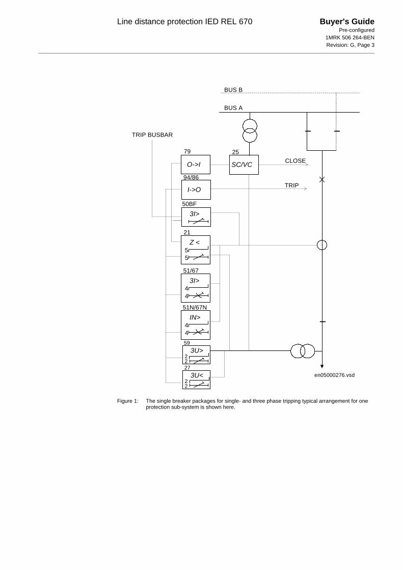
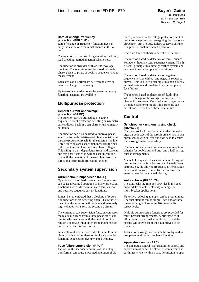
Figure 1: The single breaker packages for single- and three phase tripping typical arrangement for one protection sub-system is shown here.
Z <55
SC/VCO->I
3I>44
IN>44
I->O
CLOSE
TRIP
BUS A
BUS B
21
51/67
51N/67N
79 25
94/86
3I>50BF
TRIP BUSBAR
en05000276.vsd
3U>59
3U<27
2
22
2
Line distance protection IED REL 670 Buyer's GuidePre-configured
1MRK 506 264-BENRevision: G, Page 4
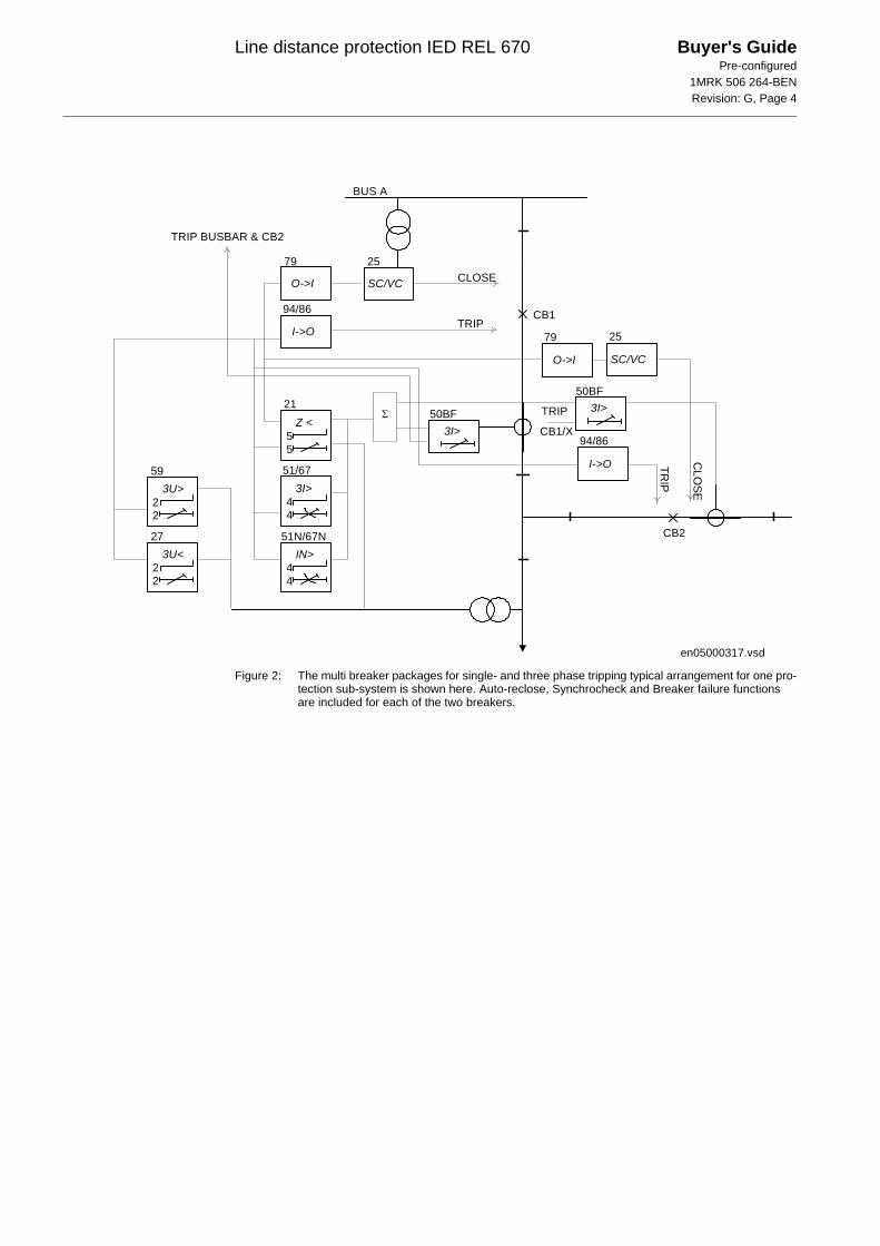
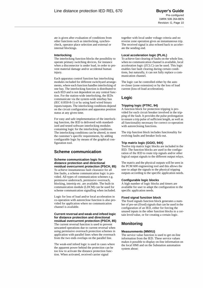
Figure 2: The multi breaker packages for single- and three phase tripping typical arrangement for one pro-tection sub-system is shown here. Auto-reclose, Synchrocheck and Breaker failure functions are included for each of the two breakers.
Z <55
SC/VCO->I
3I>44
IN>44
3U>22
3U<22
I->O
CLOSE
TRIP
BUS A
21
51/67
51N/67N
59
27
79 25
94/86
3I>50BF
TRIP BUSBAR & CB2
3I>50BF
Σ
SC/VCO->I
I->O CLO
SE
TRIP
25
94/86
79
en05000317.vsd
TRIP
CB1/X
CB1
CB2
Line distance protection IED REL 670 Buyer's GuidePre-configured
1MRK 506 264-BENRevision: G, Page 5
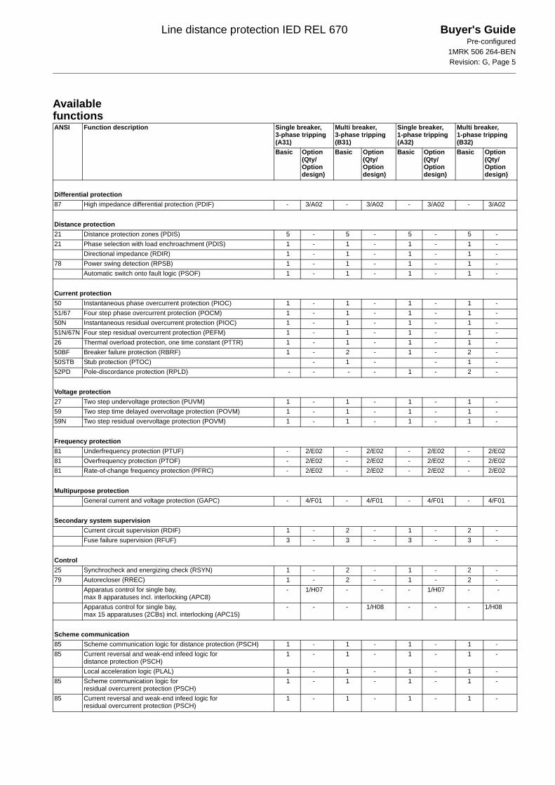
Available functionsANSI Function description Single breaker,
3-phase tripping (A31)
Multi breaker, 3-phase tripping (B31)
Single breaker, 1-phase tripping (A32)
Multi breaker, 1-phase tripping (B32)
Basic Option (Qty/ Option design)
Basic Option (Qty/ Option design)
Basic Option (Qty/ Option design)
Basic Option (Qty/ Option design)
Differential protection87 High impedance differential protection (PDIF) - 3/A02 - 3/A02 - 3/A02 - 3/A02
Distance protection21 Distance protection zones (PDIS) 5 - 5 - 5 - 5 -21 Phase selection with load enchroachment (PDIS) 1 - 1 - 1 - 1 -
Directional impedance (RDIR) 1 - 1 - 1 - 1 -78 Power swing detection (RPSB) 1 - 1 - 1 - 1 -
Automatic switch onto fault logic (PSOF) 1 - 1 - 1 - 1 -
Current protection50 Instantaneous phase overcurrent protection (PIOC) 1 - 1 - 1 - 1 -51/67 Four step phase overcurrent protection (POCM) 1 - 1 - 1 - 1 -50N Instantaneous residual overcurrent protection (PIOC) 1 - 1 - 1 - 1 -51N/67N Four step residual overcurrent protection (PEFM) 1 - 1 - 1 - 1 -26 Thermal overload protection, one time constant (PTTR) 1 - 1 - 1 - 1 -50BF Breaker failure protection (RBRF) 1 - 2 - 1 - 2 -50STB Stub protection (PTOC) - 1 - - 1 -52PD Pole-discordance protection (RPLD) - - - - 1 - 2 -
Voltage protection27 Two step undervoltage protection (PUVM) 1 - 1 - 1 - 1 -59 Two step time delayed overvoltage protection (POVM) 1 - 1 - 1 - 1 -59N Two step residual overvoltage protection (POVM) 1 - 1 - 1 - 1 -
Frequency protection81 Underfrequency protection (PTUF) - 2/E02 - 2/E02 - 2/E02 - 2/E0281 Overfrequency protection (PTOF) - 2/E02 - 2/E02 - 2/E02 - 2/E0281 Rate-of-change frequency protection (PFRC) - 2/E02 - 2/E02 - 2/E02 - 2/E02
Multipurpose protectionGeneral current and voltage protection (GAPC) - 4/F01 - 4/F01 - 4/F01 - 4/F01
Secondary system supervisionCurrent circuit supervision (RDIF) 1 - 2 - 1 - 2 -Fuse failure supervision (RFUF) 3 - 3 - 3 - 3 -
Control25 Synchrocheck and energizing check (RSYN) 1 - 2 - 1 - 2 -79 Autorecloser (RREC) 1 - 2 - 1 - 2 -
Apparatus control for single bay, max 8 apparatuses incl. interlocking (APC8)
- 1/H07 - - - 1/H07 - -
Apparatus control for single bay, max 15 apparatuses (2CBs) incl. interlocking (APC15)
- - - 1/H08 - - - 1/H08
Scheme communication85 Scheme communication logic for distance protection (PSCH) 1 - 1 - 1 - 1 -85 Current reversal and weak-end infeed logic for
distance protection (PSCH) 1 - 1 - 1 - 1 -
Local acceleration logic (PLAL) 1 - 1 - 1 - 1 -85 Scheme communication logic for
residual overcurrent protection (PSCH) 1 - 1 - 1 - 1 -
85 Current reversal and weak-end infeed logic for residual overcurrent protection (PSCH)
1 - 1 - 1 - 1 -
Line distance protection IED REL 670 Buyer's GuidePre-configured
1MRK 506 264-BENRevision: G, Page 6
Functionality Differential protection
High impedance differential protection (PDIF, 87)The high impedance differential protection can be used when the involved CT cores have same turn ratio and similar magnetizing characteristic. It uti-lizes an external summation of the phases and neu-tral current and a series resistor and a voltage dependent resistor externally to the relay.
Distance protection
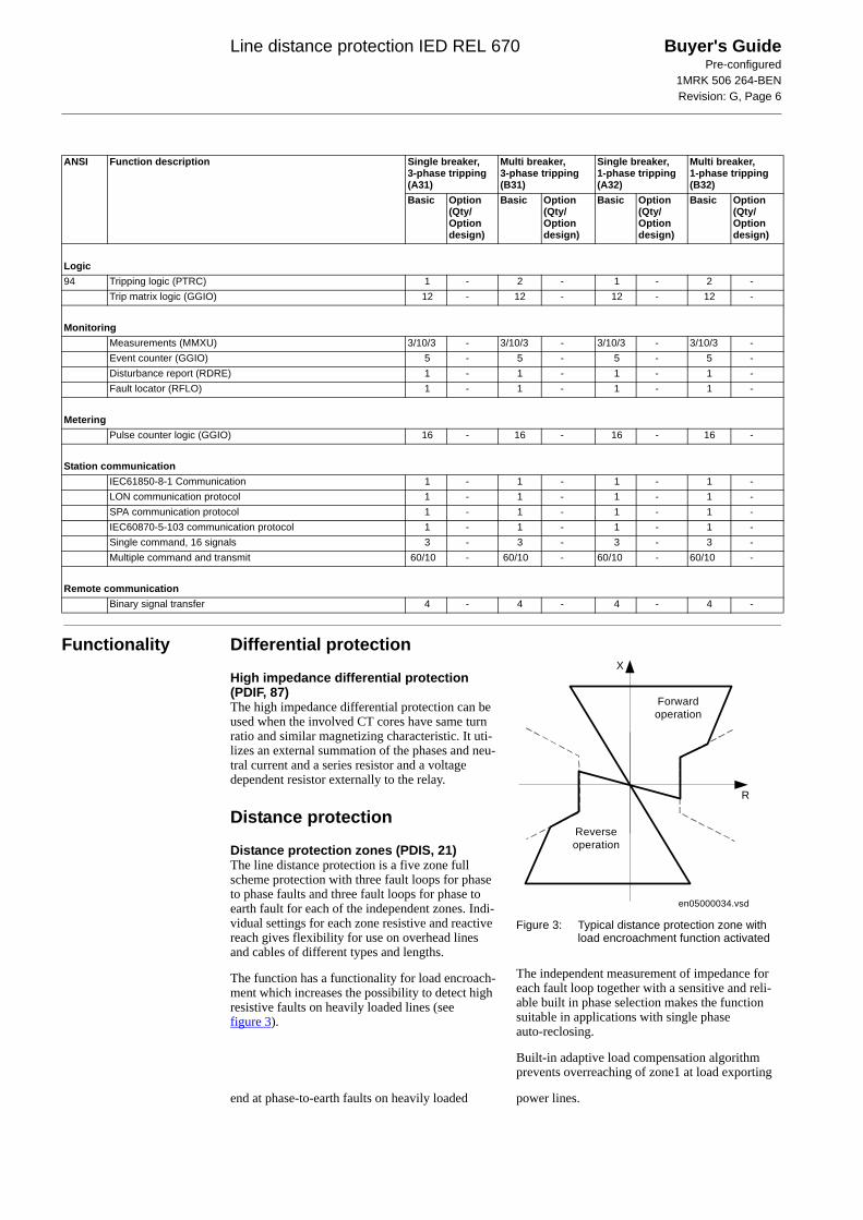
Distance protection zones (PDIS, 21)The line distance protection is a five zone full scheme protection with three fault loops for phase to phase faults and three fault loops for phase to earth fault for each of the independent zones. Indi-vidual settings for each zone resistive and reactive reach gives flexibility for use on overhead lines and cables of different types and lengths.
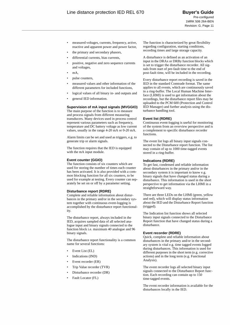
The function has a functionality for load encroach-ment which increases the possibility to detect high resistive faults on heavily loaded lines (see figure 3).
Figure 3: Typical distance protection zone with load encroachment function activated
The independent measurement of impedance for each fault loop together with a sensitive and reli-able built in phase selection makes the function suitable in applications with single phase auto-reclosing.
Built-in adaptive load compensation algorithm prevents overreaching of zone1 at load exporting
end at phase-to-earth faults on heavily loaded power lines.
Logic94 Tripping logic (PTRC) 1 - 2 - 1 - 2 -
Trip matrix logic (GGIO) 12 - 12 - 12 - 12 -
MonitoringMeasurements (MMXU) 3/10/3 - 3/10/3 - 3/10/3 - 3/10/3 -Event counter (GGIO) 5 - 5 - 5 - 5 -Disturbance report (RDRE) 1 - 1 - 1 - 1 -Fault locator (RFLO) 1 - 1 - 1 - 1 -
MeteringPulse counter logic (GGIO) 16 - 16 - 16 - 16 -
Station communicationIEC61850-8-1 Communication 1 - 1 - 1 - 1 -LON communication protocol 1 - 1 - 1 - 1 -SPA communication protocol 1 - 1 - 1 - 1 -IEC60870-5-103 communication protocol 1 - 1 - 1 - 1 -Single command, 16 signals 3 - 3 - 3 - 3 -Multiple command and transmit 60/10 - 60/10 - 60/10 - 60/10 -
Remote communicationBinary signal transfer 4 - 4 - 4 - 4 -
ANSI Function description Single breaker, 3-phase tripping (A31)
Multi breaker, 3-phase tripping (B31)
Single breaker, 1-phase tripping (A32)
Multi breaker, 1-phase tripping (B32)
Basic Option (Qty/ Option design)
Basic Option (Qty/ Option design)
Basic Option (Qty/ Option design)
Basic Option (Qty/ Option design)
en05000034.vsd
R
X
Forwardoperation
Reverseoperation
Line distance protection IED REL 670 Buyer's GuidePre-configured
1MRK 506 264-BENRevision: G, Page 7
The distance protection zones can operate, inde-pendent of each other, in directional (forward or reverse) or non-directional mode. This makes them suitable, together with different communication schemes, for the protection of power lines and cables in complex network configurations, such as parallel lines, multi-terminal lines etc.
Power swing detection (RPSB, 78)Power swings may occur after disconnection of heavy loads or trip of big generation plants.
Power swing detection function is used to detect power swings and initiate block of selected dis-tance protection zones. Occurrence of earth fault currents during a power swing can block the power swing detection function to allow fault clearance.
Automatic switch onto fault logic (PSOF)Automatic switch onto fault logic is a function that gives an instantaneous trip at closing of breaker onto a fault. A dead line detection check is pro-vided to activate the function when the line is dead.
Current protection
Instantaneous phase overcurrent protection (PIOC, 50)The instantaneous three phase overcurrent function has a low transient overreach and short tripping time to allow use as a high set short-circuit protec-tion function, with the reach limited to less than typical eighty percent of the power line at mini-mum source impedance.
Four step phase overcurrent protection (POCM, 51_67)The four step phase overcurrent function has an inverse or definite time delay independent for each step separately.
All IEC and ANSI time delayed characteristics are available together with an optional user defined time characteristic.
The function can be set to be directional or non-directional independently for each of the steps.
Instantaneous residual overcurrent protection (PIOC, 50N)The single input overcurrent function has a low transient overreach and short tripping times to allow use as a high set short circuit protection function, with the reach limited to less than typical eighty percent of the power line at minimum source impedance. The function can be configured to measure the residual current from the three phase current inputs or the current from a separate current input.
Four step residual overcurrent protection (PEFM, 51N/67N)The four step single input overcurrent function has an inverse or definite time delay independent for each step separately.
All IEC and ANSI time delayed characteristics are available together with an optional user defined characteristic.
The function can be set to be directional, forward, reverse or non-directional independently for each of the steps.
A second harmonic blocking can be set individu-ally for each step.
The function can be used as main protection for phase to earth faults.
The function can be used to provide a system back-up e.g. in the case of the primary protection being out of service due to communication or volt-age transformer circuit failure.
Directional operation can be combined together with corresponding communication blocks into permissive or blocking teleprotection scheme. Current reversal and weak-end infeed functionality are available as well.
The function can be configured to measure the residual current from the three phase current inputs or the current from a separate current input.
Thermal overload protection, one time constant (PTTR, 26)The increasing utilizing of the power system closer to the thermal limits have generated a need of a thermal overload function also for power lines.
A thermal overload will often not be detected by other protection functions and the introduction of the thermal overload function can allow the pro-tected circuit to operate closer to the thermal lim-its.
The three phase current measuring function has an I2t characteristic with settable time constant and a thermal memory.
An alarm level gives early warning to allow opera-tors to take action well before the line will be tripped.
Breaker failure protection (RBRF, 50BF)The circuit breaker failure function ensures fast back-up tripping of surrounding breakers. The breaker failure protection operation can be current based, contact based or adaptive combination between these two principles.
A current check with extremely short reset time is used as a check criteria to achieve a high security against unnecessary operation.
The breaker failure protection can be single- or three-phase started to allow use with single phase
Line distance protection IED REL 670 Buyer's GuidePre-configured
1MRK 506 264-BENRevision: G, Page 8
tripping applications. For the three-phase version of the breaker failure protection the current criteria can be set to operate only if two out of four e.g. two phases or one phase plus the residual current starts. This gives a higher security to the back-up trip command.
The function can be programmed to give a single- or three phase re-trip of the own breaker to avoid unnecessary tripping of surrounding breakers at an incorrect starting due to mistakes during testing.
Stub protection (PTOC, 50STB)When a power line is taken out of service for maintenance and the line disconnector is opened in multi-breaker arrangements the voltage transform-ers will mostly be outside on the disconnected part. The primary line distance protection will thus not be able to operate and must be blocked.
The stub protection covers the zone between the current transformers and the open disconnector. The three phase instantaneous overcurrent function is released from a NO (b) auxiliary contact on the line disconnector.
Pole discordance protection (RPLD, 52PD)Single pole operated circuit breakers can due to electrical or mechanical failures end up with the different poles in different positions (close-open). This can cause negative and zero sequence cur-rents which gives thermal stress on rotating machines and can cause unwanted operation of zero sequence current functions.
Normally the own breaker is tripped to correct the positions. If the situation consists the remote end can be intertripped to clear the unsymmetrical load situation.
The pole discordance function operates based on information from auxiliary contacts of the circuit breaker for the three phases with additional criteria from unsymmetrical phase current when required.
Voltage protection
Two step undervoltage protection (PUVM, 27)Undervoltages can occur in the power system dur-ing faults or abnormal conditions. The function can be used to open circuit breakers to prepare for system restoration at power outages or as long-time delayed back-up to primary protection.
The function has two voltage steps, each with inverse or definite time delay.
Two step overvoltage protection (POVM, 59)Overvoltages will occur in the power system dur-ing abnormal conditions such as sudden power loss, tap changer regulating failures, open line ends on long lines.
The function can be used as open line end detector, normally then combined with directional reactive over-power function or as system voltage supervi-sion, normally then giving alarm only or switching in reactors or switch out capacitor banks to control the voltage.
The function has two voltage steps, each of them with inverse or definite time delayed.
The overvoltage function has an extremely high reset ratio to allow setting close to system service voltage.
Two step residual overvoltage protection (POVM, 59N)Residual voltages will occur in the power system during earth faults.
The function can be configured to calculate the residual voltage from the three phase voltage input transformers or from a single phase voltage input transformer fed from an open delta or neutral point voltage transformer.
The function has two voltage steps, each with inverse or definite time delayed.
Frequency protection
Underfrequency protection (PTUF, 81)Underfrequency occurs as a result of lack of gener-ation in the network.
The function can be used for load shedding sys-tems, remedial action schemes, gas turbine start-up etc.
The function is provided with an undervoltage blocking. The operation may be based on single phase, phase-to-phase or positive sequence voltage measurement.
Up to two independent under frequency function instances are available.
Overfrequency protection (PTOF, 81)Overfrequency will occur at sudden load drops or shunt faults in the power network. In some cases close to generating part governor problems can also cause overfrequency.
The function can be used for generation shedding, remedial action schemes etc. It can also be used as a sub-nominal frequency stage initiating load restoring.
The function is provided with an undervoltage blocking. The operation may be based on single phase, phase-to-phase or positive sequence voltage measurement.
Up to two independent over frequency function instances are available.
Line distance protection IED REL 670 Buyer's GuidePre-configured
1MRK 506 264-BENRevision: G, Page 9
Rate-of-change frequency protection (PFRC, 81)Rate of change of frequency function gives an early indication of a main disturbance in the sys-tem.
The function can be used for generation shedding, load shedding, remedial action schemes etc.
The function is provided with an undervoltage blocking. The operation may be based on single phase, phase-to-phase or positive sequence voltage measurement.
Each step can discriminate between positive or negative change of frequency.
Up to two independent rate-of-change frequency function instances are available.
Multipurpose protection
General current and voltage protection (GAPC)The function can be utilized as a negative sequence current protection detecting unsymmetri-cal conditions such as open phase or unsymmetri-cal faults.
The function can also be used to improve phase selection for high resistive earth faults, outside the distance protection reach, for the transmission line. Three functions are used which measures the neu-tral current and each of the three phase voltages. This will give an independence from load currents and this phase selection will be used in conjunc-tion with the detection of the earth fault from the directional earth fault protection function.
Secondary system supervision
Current circuit supervision (RDIF)Open or short circuited current transformer cores can cause unwanted operation of many protection functions such as differential, earth fault current and negative sequence current functions.
It must be remembered that a blocking of protec-tion functions at an occurring open CT circuit will mean that the situation will remain and extremely high voltages will stress the secondary circuit.
The current circuit supervision function compares the residual current from a three phase set of cur-rent transformer cores with the neutral point cur-rent on a separate input taken from another set of cores on the current transformer.
A detection of a difference indicates a fault in the circuit and is used as alarm or to block protection functions expected to give unwanted tripping.
Fuse failure supervision (RFUF)Failures in the secondary circuits of the voltage transformer can cause unwanted operation of dis-
tance protection, undervoltage protection, neutral point voltage protection, energizing function (syn-chrocheck) etc. The fuse failure supervision func-tion prevents such unwanted operations.
There are three methods to detect fuse failures.
The method based on detection of zero sequence voltage without any zero sequence current. This is a useful principle in a directly earthed system and can detect one or two phase fuse failures.
The method based on detection of negative sequence voltage without any negative sequence current. This is a useful principle in a non-directly earthed system and can detect one or two phase fuse failures.
The method based on detection of du/dt-di/dt where a change of the voltage is compared to a change in the current. Only voltage changes means a voltage transformer fault. This principle can detect one, two or three phase fuse failures.
Control
Synchrocheck and energizing check (RSYN, 25)The synchrocheck function checks that the volt-ages on both sides of the circuit breaker are in syn-chronism, or with at least one side dead to ensure that closing can be done safely.
The function includes a built-in voltage selection scheme for double bus and one- and a half or ring busbar arrangements.
Manual closing as well as automatic reclosing can be checked by the function and can have different settings, e.g. the allowed frequency difference can be set to allow wider limits for the auto-reclose attempt than for the manual closing.
Autorecloser (RREC, 79)The autoreclosing function provides high-speed and/or delayed auto-reclosing for single or multi-breaker applications.
Up to five reclosing attempts can be programmed. The first attempt can be single-, two and/or three phase for single phase or multi-phase faults respectively.
Multiple autoreclosing functions are provided for multi-breaker arrangements. A priority circuit allows one circuit breaker to close first and the second will only close if the fault proved to be transient.
Each autoreclosing function can be configured to co-operate with a synchrocheck function.
Apparatus control (APC)The apparatus control is a function for control and supervision of circuit breakers, disconnectors and earthing switches within a bay. Permission to oper-
Line distance protection IED REL 670 Buyer's GuidePre-configured
1MRK 506 264-BENRevision: G, Page 10
ate is given after evaluation of conditions from other functions such as interlocking, synchro-check, operator place selection and external or internal blockings.
InterlockingThe interlocking function blocks the possibility to operate primary switching devices, for instance when a disconnector is under load, in order to pre-vent material damage and/or accidental human injury.
Each apparatus control function has interlocking modules included for different switchyard arrange-ments, where each function handles interlocking of one bay. The interlocking function is distributed to each IED and is not dependent on any central func-tion. For the station-wide interlocking, the IEDs communicate via the system-wide interbay bus (IEC 61850-8-1) or by using hard wired binary inputs/outputs. The interlocking conditions depend on the circuit configuration and apparatus position status at any given time.
For easy and safe implementation of the interlock-ing function, the IED is delivered with standard-ized and tested software interlocking modules containing logic for the interlocking conditions. The interlocking conditions can be altered, to meet the customer’s specific requirements, by adding configurable logic by means of the graphical con-figuration tool.
Scheme communication
Scheme communication logic for distance protection and directional residual overcurrent protection (PSCH, 85)To achieve instantaneous fault clearance for all line faults, a scheme communication logic is pro-vided. All types of communication schemes e.g. permissive underreach, permissive overreach, blocking, intertrip etc. are available. The built-in communication module (LDCM) can be used for scheme communication signalling when included.
Logic for loss of load and/or local acceleration in co-operation with autoreclose function is also pro-vided for application where no communication channel is available.
Current reversal and weak-end infeed logic for distance protection and directional residual overcurrent protection (PSCH, 85)The current reversal function is used to prevent unwanted operations due to current reversal when using permissive overreach protection schemes in application with parallel lines when the overreach from the two ends overlaps on the parallel line.
The weak-end infeed logic is used in cases where the apparent power behind the protection can be too low to activate the distance protection func-tion. When activated, received carrier signal
together with local under voltage criteria and no reverse zone operation gives an instantaneous trip. The received signal is also echoed back to acceler-ate the sending end.
Local acceleration logic (PLAL)To achieve fast clearing of faults on the whole line, when no communication channel is available, local acceleration logic (ZCLC) can be used. This logic enables fast fault clearing during certain condi-tions, but naturally, it can not fully replace a com-munication channel.
The logic can be controlled either by the auto re-closer (zone extension) or by the loss of load current (loss-of-load acceleration).
Logic
Tripping logic (PTRC, 94)A function block for protection tripping is pro-vided for each circuit breaker involved in the trip-ping of the fault. It provides the pulse prolongation to ensure a trip pulse of sufficient length, as well as all functionality necessary for correct co-operation with autoreclosing functions.
The trip function block includes functionality for evolving faults and breaker lock-out.
Trip matrix logic (GGIO, 94X)Twelve trip matrix logic blocks are included in the IED. The function blocks are used in the configu-ration of the IED to route trip signals and/or other logical output signals to the different output relays.
The matrix and the physical outputs will be seen in the PCM 600 engineering tool and this allows the user to adapt the signals to the physical tripping outputs according to the specific application needs.
Configurable logic blocksA high number of logic blocks and timers are available for user to adapt the configuration to the specific application needs.
Fixed signal function blockThe fixed signals function block generates a num-ber of pre-set (fixed) signals that can be used in the configuration of an IED, either for forcing the unused inputs in the other function blocks to a cer-tain level/value, or for creating a certain logic.
Monitoring
Measurements (MMXU)The service value function is used to get on-line information from the IED. These service values makes it possible to display on-line information on the local HMI and on the Substation automation system about:
Line distance protection IED REL 670 Buyer's GuidePre-configured
1MRK 506 264-BENRevision: G, Page 11
• measured voltages, currents, frequency, active, reactive and apparent power and power factor,
• the primary and secondary phasors,• differential currents, bias currents,• positive, negative and zero sequence currents
and voltages,• mA,• pulse counters,• measured values and other information of the
different parameters for included functions,• logical values of all binary in- and outputs and• general IED information.
Supervision of mA input signals (MVGGIO)The main purpose of the function is to measure and process signals from different measuring transducers. Many devices used in process control represent various parameters such as frequency, temperature and DC battery voltage as low current values, usually in the range 4-20 mA or 0-20 mA.
Alarm limits can be set and used as triggers, e.g. to generate trip or alarm signals.
The function requires that the IED is equipped with the mA input module.
Event counter (GGIO)The function consists of six counters which are used for storing the number of times each counter has been activated. It is also provided with a com-mon blocking function for all six counters, to be used for example at testing. Every counter can sep-arately be set on or off by a parameter setting.
Disturbance report (RDRE)Complete and reliable information about distur-bances in the primary and/or in the secondary sys-tem together with continuous event-logging is accomplished by the disturbance report functional-ity.
The disturbance report, always included in the IED, acquires sampled data of all selected ana-logue input and binary signals connected to the function block i.e. maximum 40 analogue and 96 binary signals.
The disturbance report functionality is a common name for several functions:
• Event List (EL)• Indications (IND)• Event recorder (ER)• Trip Value recorder (TVR)• Disturbance recorder (DR)• Fault Locator (FL)
The function is characterized by great flexibility regarding configuration, starting conditions, recording times and large storage capacity.
A disturbance is defined as an activation of an input in the DRAx or DRBy function blocks which is set to trigger the disturbance recorder. All sig-nals from start of pre-fault time to the end of post-fault time, will be included in the recording.
Every disturbance report recording is saved in the IED in the standard Comtrade format. The same applies to all events, which are continuously saved in a ring-buffer. The Local Human Machine Inter-face (LHMI) is used to get information about the recordings, but the disturbance report files may be uploaded to the PCM 600 (Protection and Control IED Manager) and further analysis using the dis-turbance handling tool.
Event list (RDRE)Continuous event-logging is useful for monitoring of the system from an overview perspective and is a complement to specific disturbance recorder functions.
The event list logs all binary input signals con-nected to the Disturbance report function. The list may contain of up to 1000 time-tagged events stored in a ring-buffer.
Indications (RDRE)To get fast, condensed and reliable information about disturbances in the primary and/or in the secondary system it is important to know e.g. binary signals that have changed status during a disturbance. This information is used in the short perspective to get information via the LHMI in a straightforward way.
There are three LEDs on the LHMI (green, yellow and red), which will display status information about the IED and the Disturbance Report function (trigged).
The Indication list function shows all selected binary input signals connected to the Disturbance Report function that have changed status during a disturbance.
Event recorder (RDRE)Quick, complete and reliable information about disturbances in the primary and/or in the second-ary system is vital e.g. time tagged events logged during disturbances. This information is used for different purposes in the short term (e.g. corrective actions) and in the long term (e.g. Functional Analysis).
The event recorder logs all selected binary input signals connected to the Disturbance Report func-tion. Each recording can contain up to 150 time-tagged events.
The event recorder information is available for the disturbances locally in the IED.
Line distance protection IED REL 670 Buyer's GuidePre-configured
1MRK 506 264-BENRevision: G, Page 12
The event recording information is an integrated part of the disturbance record (Comtrade file).
Trip value recorder (RDRE)Information about the pre-fault and fault values for currents and voltages are vital for the disturbance evaluation.
The Trip value recorder calculates the values of all selected analogue input signals connected to the Disturbance report function. The result is magni-tude and phase angle before and during the fault for each analogue input signal.
The trip value recorder information is available for the disturbances locally in the IED.
The trip value recorder information is an inte-grated part of the disturbance record (Comtrade file).
Disturbance recorder (RDRE)The Disturbance Recorder function supplies fast, complete and reliable information about distur-bances in the power system. It facilitates under-standing system behavior and related primary and secondary equipment during and after a distur-bance. Recorded information is used for different purposes in the short perspective (e.g. corrective actions) and long perspective (e.g. Functional Analysis).
The Disturbance Recorder acquires sampled data from all selected analogue input and binary signals connected to the Disturbance Report function (maximum 40 analog and 96 binary signals). The binary signals are the same signals as available under the event recorder function.
The function is characterized by great flexibility and is not dependent on the operation of protection functions. It can record disturbances not detected by protection functions.
The disturbance recorder information for the last 100 disturbances are saved in the IED and the Local Human Machine Interface (LHMI) is used to view the list of recordings.
Event function (EV)When using a Substation Automation system with LON or SPA communication, time-tagged events can be sent at change or cyclically from the IED to the station level. These events are created from any available signal in the IED that is connected to the Event function block. The event function block is used for LON and SPA communication.
Analog and double indication values are also transferred through the event block.
Fault locator (RFLO)The accurate fault locator is an essential compo-nent to minimize the outages after a persistent fault and/or to pin-point a weak spot on the line.
The built-in fault locator is an impedance measur-ing function giving the distance to the fault in per-cent, km or miles. The main advantage is the high accuracy achieved by compensating for load cur-rent and for the mutual zero sequence effect on double circuit lines.
The compensation includes setting of the remote and local sources and calculation of the distribu-tion of fault currents from each side. This distribu-tion of fault current, together with recorded load (pre-fault) currents, is used to exactly calculate the fault position. The fault can be recalculated with new source data at the actual fault to further increase the accuracy.
Specially on heavily loaded long lines (where the fault locator is most important) where the source voltage angles can be up to 35-40 degrees apart the accuracy can be still maintained with the advanced compensation included in fault locator.
Metering
Pulse counter logic (GGIO)The pulse counter logic function counts externally generated binary pulses, for instance pulses com-ing from an external energy meter, for calculation of energy consumption values. The pulses are cap-tured by the binary input module and then read by the pulse counter function. A scaled service value is available over the station bus. The special Binary input module with enhanced pulse counting capabilities must be ordered to achieve this func-tionality.
Basic IED functions
Time synchronizationUse the time synchronization source selector to select a common source of absolute time for the IED when it is a part of a protection system. This makes comparison of events and disturbance data between all IEDs in a SA system possible.
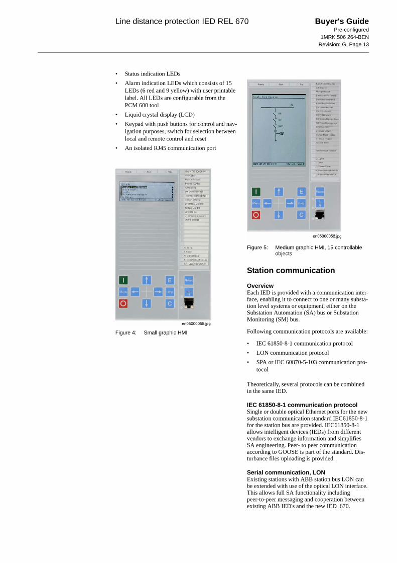
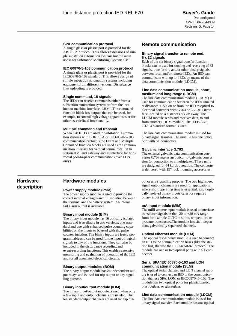
Human machine interfaceThe local human machine interface is available in a small, and a medium sized model. The principle difference between the two is the size of the LCD. The small size LCD can display seven line of text and the medium size LCD can display the single line diagram with up to 15 objects on each page.
Six SLD pages can be defined.
The local human machine interface is equipped with an LCD that can display the single line dia-gram with up to 15 objects.
The local human-machine interface is simple and easy to understand – the whole front plate is divided into zones, each of them with a well-defined functionality:
Line distance protection IED REL 670 Buyer's GuidePre-configured
1MRK 506 264-BENRevision: G, Page 13
• Status indication LEDs• Alarm indication LEDs which consists of 15
LEDs (6 red and 9 yellow) with user printable label. All LEDs are configurable from the PCM 600 tool
• Liquid crystal display (LCD)• Keypad with push buttons for control and nav-
igation purposes, switch for selection between local and remote control and reset
• An isolated RJ45 communication port
Figure 4: Small graphic HMI
Figure 5: Medium graphic HMI, 15 controllable objects
Station communication
OverviewEach IED is provided with a communication inter-face, enabling it to connect to one or many substa-tion level systems or equipment, either on the Substation Automation (SA) bus or Substation Monitoring (SM) bus.
Following communication protocols are available:
• IEC 61850-8-1 communication protocol• LON communication protocol• SPA or IEC 60870-5-103 communication pro-
tocol
Theoretically, several protocols can be combined in the same IED.
IEC 61850-8-1 communication protocolSingle or double optical Ethernet ports for the new substation communication standard IEC61850-8-1 for the station bus are provided. IEC61850-8-1 allows intelligent devices (IEDs) from different vendors to exchange information and simplifies SA engineering. Peer- to peer communication according to GOOSE is part of the standard. Dis-turbance files uploading is provided.
Serial communication, LONExisting stations with ABB station bus LON can be extended with use of the optical LON interface. This allows full SA functionality including peer-to-peer messaging and cooperation between existing ABB IED's and the new IED 670.
Line distance protection IED REL 670 Buyer's GuidePre-configured
1MRK 506 264-BENRevision: G, Page 14
SPA communication protocolA single glass or plastic port is provided for the ABB SPA protocol. This allows extensions of sim-ple substation automation systems but the main use is for Substation Monitoring Systems SMS.
IEC 60870-5-103 communication protocolA single glass or plastic port is provided for the IEC60870-5-103 standard. This allows design of simple substation automation systems including equipment from different vendors. Disturbance files uploading is provided.
Single command, 16 signalsThe IEDs can receive commands either from a substation automation system or from the local human-machine interface, LHMI. The command function block has outputs that can be used, for example, to control high voltage apparatuses or for other user defined functionality.
Multiple command and transmitWhen 670 IED's are used in Substation Automa-tion systems with LON, SPA or IEC60870-5-103 communication protocols the Event and Multiple Command function blocks are used as the commu-nication interface for vertical communication to station HMI and gateway and as interface for hori-zontal peer-to-peer communication (over LON only).
Remote communication
Binary signal transfer to remote end, 6 x 32 signalsEach of the six binary signal transfer function blocks can be used for sending and receiving of 32 signals, transfer trip and/or other binary signals between local and/or remote IEDs. An IED can communicate with up to IEDs by means of the data communication module (LDCM).
Line data communication module, short, medium and long range (LDCM)The line data communication module (LDCM) is used for communication between the IEDs situated at distances <150 km or from the IED to optical to electrical converter with G.703 or G.703E1 inter-face located on a distances <3 km away. The LDCM module sends and receives data, to and from another LDCM module. The IEEE/ANSI C37.94 standard format is used.
The line data communication module is used for binary signal transfer. The module has one optical port with ST connectors.
Galvanic interface G.703The external galvanic data communication con-verter G.703 makes an optical-to-galvanic conver-sion for connection to a multiplexer. These units are designed for 64 kbit/s operation. The converter is delivered with 19” rack mounting accessories.
Hardware description
Hardware modules
Power supply module (PSM)The power supply module is used to provide the correct internal voltages and full isolation between the terminal and the battery system. An internal fail alarm output is available.
Binary input module (BIM)The binary input module has 16 optically isolated inputs and is available in two versions, one stan-dard and one with enhanced pulse counting capa-bilities on the inputs to be used with the pulse counter function. The binary inputs are freely pro-grammable and can be used for the input of logical signals to any of the functions. They can also be included in the disturbance recording and event-recording functions. This enables extensive monitoring and evaluation of operation of the IED and for all associated electrical circuits.
Binary output modules (BOM)The binary output module has 24 independent out-put relays and is used for trip output or any signal-ling purpose.
Binary input/output module (IOM)The binary input/output module is used when only a few input and output channels are needed. The ten standard output channels are used for trip out-
put or any signalling purpose. The two high speed signal output channels are used for applications where short operating time is essential. Eight opti-cally isolated binary inputs cater for required binary input information.
mA input module (MIM)The milli-ampere input module is used to interface transducer signals in the –20 to +20 mA range from for example OLTC position, temperature or pressure transducers.The module has six indepen-dent, galvanically separated channels.
Optical ethernet module (OEM)The optical fast-ethernet module is used to connect an IED to the communication buses (like the sta-tion bus) that use the IEC 61850-8-1 protocol. The module has one or two optical ports with ST con-nectors.
Serial SPA/IEC 60870-5-103 and LON communication module (SLM)The optical serial channel and LON channel mod-ule is used to connect an IED to the communica-tion that use SPA, LON, or IEC60870–5–103. The module has two optical ports for plastic/plastic, plastic/glass, or glass/glass.
Line data communication module (LDCM)The line data communication module is used for binary signal transfer. Each module has one optical

Line distance protection IED REL 670 Buyer's GuidePre-configured
1MRK 506 264-BENRevision: G, Page 15
port, one for each remote end to which the IED communicates.
Alternative cards for Short range (900 nm multi mode) are available.
Transformer input module (TRM)The transformer input module is used to galvani-cally separate and transform the secondary cur-rents and voltages generated by the measuring
transformers. The module has twelve inputs in dif-ferent combinations.
High impedance resistor unitThe high impedance resistor unit, with resistors for pick-up value setting and a voltage dependent resistor, is available in a single phase unit and a three phase unit. Both are mounted on a 1/1 19 inch apparatus plate with compression type term-nals.
Layout and dimensions
Dimensions
Mounting alternativesFollowing mounting alternatives (IP40 protection from the front) are available:
• 19” rack mounting kit• Flush mounting kit with cut-out dimensions:
- 1/2 case size (h) 254.3 mm (w) 210.1 mm- 3/4 case size (h) 254.3 mm (w) 322.4mm- 1/1 case size (h) 254.3 mm (w) 434.7mm
• Wall mounting kit
See ordering for details about available mounting alternatives.
Figure 6: 1/2 x 19” case with rear cover Figure 7: Side-by-side mounting
Case size A B C D E F6U, 1/2 x 19” 265.9 223.7 201.1 242.1 252.9 205.76U, 3/4 x 19” 265.9 336.0 201.1 242.1 252.9 318.06U, 1/1 x 19” 265.9 448.1 201.1 242.1 252.9 430.3
(mm)
xx05000003.vsd
CB
E
F
A
D
xx05000004.vsd
Line distance protection IED REL 670 Buyer's GuidePre-configured
1MRK 506 264-BENRevision: G, Page 16
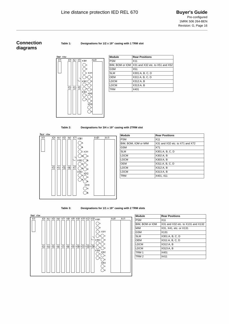
Connection diagrams
Table 1: Designations for 1/2 x 19” casing with 1 TRM slot
Table 2: Designations for 3/4 x 19” casing with 2TRM slot
Table 3: Designations for 1/1 x 19” casing with 2 TRM slots
Module Rear PositionsPSM X11BIM, BOM or IOM X31 and X32 etc. to X51 and X52GSM X51SLM X301:A, B, C, DOEM X311:A, B, C, DLDCM X312:A, BLDCM X313:A, BTRM X401
Module Rear PositionsPSM X11BIM, BOM, IOM or MIM X31 and X32 etc. to X71 and X72GSM X71SLM X301:A, B, C, DLDCM X302:A, BLDCM X303:A, BOEM X311:A, B, C, DLDCM X312:A, BLDCM X313:A, BTRM X401, 411
Module Rear PositionsPSM X11BIM, BOM or IOM X31 and X32 etc. to X131 and X132MIM X31, X41, etc. or X131GSM X131SLM X301:A, B, C, DOEM X311:A, B, C, DLDCM X312:A, BLDCM X313:A, BTRM 1 X401TRM 2 X411
Line distance protection IED REL 670 Buyer's GuidePre-configured
1MRK 506 264-BENRevision: G, Page 17
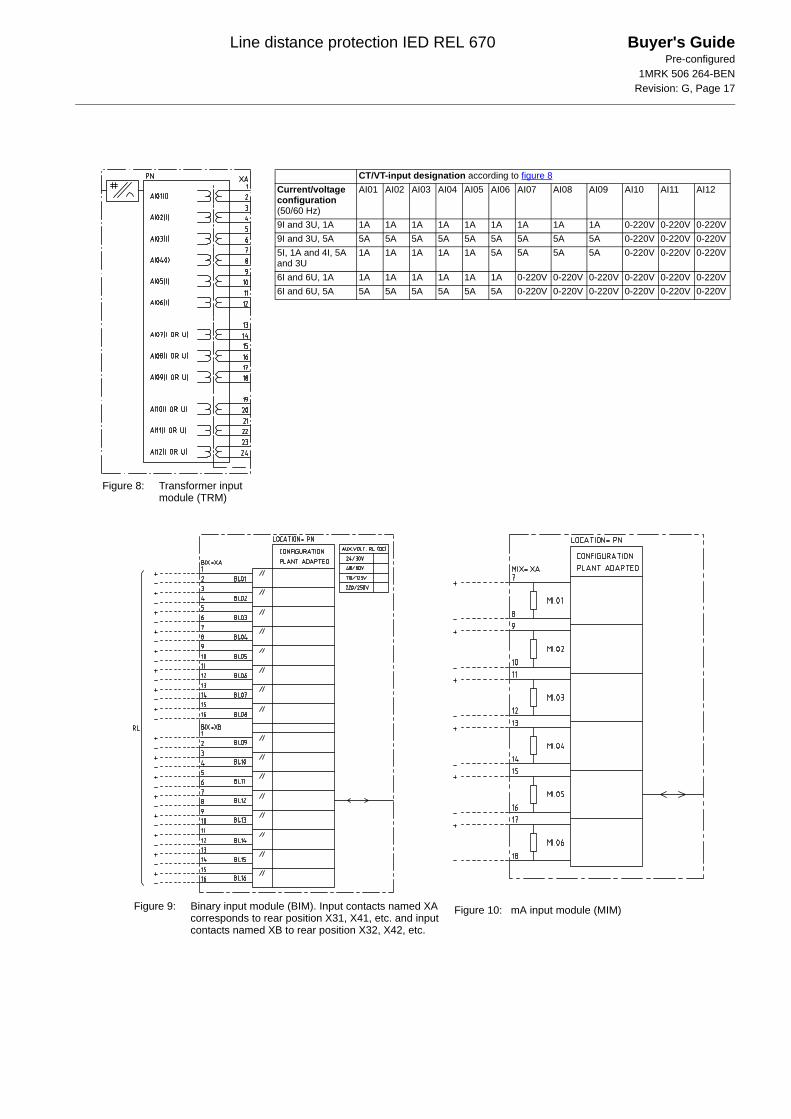
Figure 8: Transformer input module (TRM)
CT/VT-input designation according to figure 8Current/voltage configuration (50/60 Hz)
AI01 AI02 AI03 AI04 AI05 AI06 AI07 AI08 AI09 AI10 AI11 AI12
9I and 3U, 1A 1A 1A 1A 1A 1A 1A 1A 1A 1A 0-220V 0-220V 0-220V9I and 3U, 5A 5A 5A 5A 5A 5A 5A 5A 5A 5A 0-220V 0-220V 0-220V5I, 1A and 4I, 5A and 3U
1A 1A 1A 1A 1A 5A 5A 5A 5A 0-220V 0-220V 0-220V
6I and 6U, 1A 1A 1A 1A 1A 1A 1A 0-220V 0-220V 0-220V 0-220V 0-220V 0-220V6I and 6U, 5A 5A 5A 5A 5A 5A 5A 0-220V 0-220V 0-220V 0-220V 0-220V 0-220V
Figure 9: Binary input module (BIM). Input contacts named XA corresponds to rear position X31, X41, etc. and input contacts named XB to rear position X32, X42, etc.
Figure 10: mA input module (MIM)
Line distance protection IED REL 670 Buyer's GuidePre-configured
1MRK 506 264-BENRevision: G, Page 18
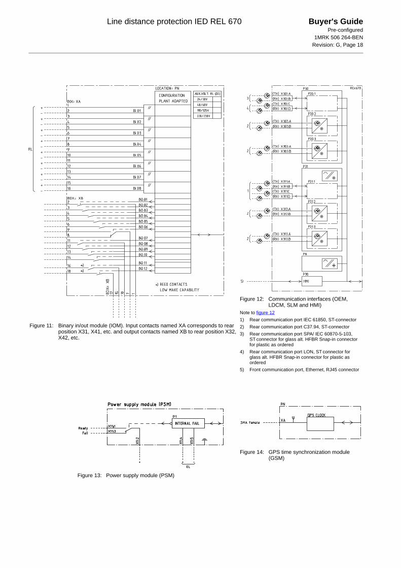
Figure 11: Binary in/out module (IOM). Input contacts named XA corresponds to rear position X31, X41, etc. and output contacts named XB to rear position X32, X42, etc.
Figure 12: Communication interfaces (OEM, LDCM, SLM and HMI)
Note to figure 121) Rear communication port IEC 61850, ST-connector2) Rear communication port C37.94, ST-connector3) Rear communication port SPA/ IEC 60870-5-103,
ST connector for glass alt. HFBR Snap-in connector for plastic as ordered
4) Rear communication port LON, ST connector for glass alt. HFBR Snap-in connector for plastic as ordered
5) Front communication port, Ethernet, RJ45 connector
Figure 13: Power supply module (PSM)
Figure 14: GPS time synchronization module (GSM)
Line distance protection IED REL 670 Buyer's GuidePre-configured
1MRK 506 264-BENRevision: G, Page 19
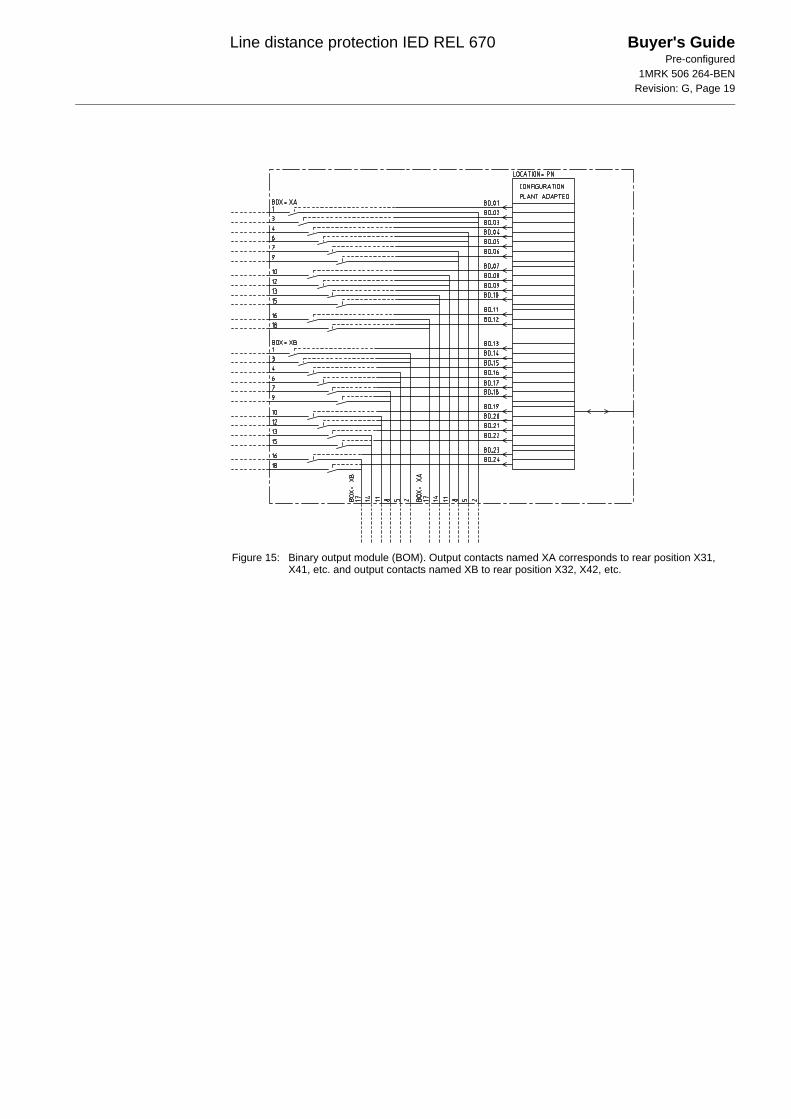
Figure 15: Binary output module (BOM). Output contacts named XA corresponds to rear position X31, X41, etc. and output contacts named XB to rear position X32, X42, etc.
Line distance protection IED REL 670 Buyer's GuidePre-configured
1MRK 506 264-BENRevision: G, Page 20
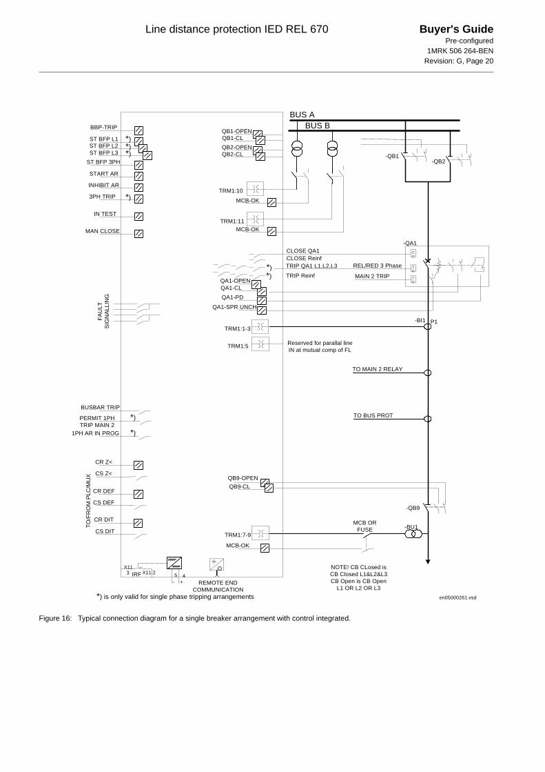
Figure 16: Typical connection diagram for a single breaker arrangement with control integrated.
CC
TC
TC
P1
-QB1-QB2
-QA1
-BI1
QB1-OPENQB1-CLQB2-OPENQB2-CL
QA1-OPENQA1-CL
QA1-SPR UNCH
QA1-PD
CLOSE QA1
TRIP QA1 L1,L2,L3
MAIN 2 TRIP
-QB9
MCB-OK
MCB-OK
BUS ABUS B
QB9-OPENQB9-CL
BBP-TRIP
ST BFP L1
ST BFP 3PH
START AR
INHIBIT AR
3PH TRIP
1PH AR IN PROG
CR Z<
CS Z<
CR DEF
CS DEF
CR DIT
CS DIT
TO/F
RO
M P
LC/M
UX
FAU
LTSI
GN
ALLI
NG
REMOTE ENDCOMMUNICATION
O
TO MAIN 2 RELAY
TO BUS PROT
MCB ORFUSE
MCB-OK
- +IRF
MAN CLOSE
BUSBAR TRIP
TRIP Reinf
CLOSE Reinf
TRM1:1-3
TRM1:7-9
TRM1:10
TRM1:11
NOTE! CB CLosed isCB Closed L1&L2&L3CB Open is CB Open
L1 OR L2 OR L3
-BU1
TRM1:5 Reserved for parallal lineIN at mutual comp of FL
PERMIT 1PHTRIP MAIN 2
IN TEST
en05000261.vsd
*)*)*)
*)
*)
*)
*)*)
REL/RED 3 Phase
ST BFP L2ST BFP L3
X11 2X113 5 4
*) is only valid for single phase tripping arrangements
Line distance protection IED REL 670 Buyer's GuidePre-configured
1MRK 506 264-BENRevision: G, Page 21
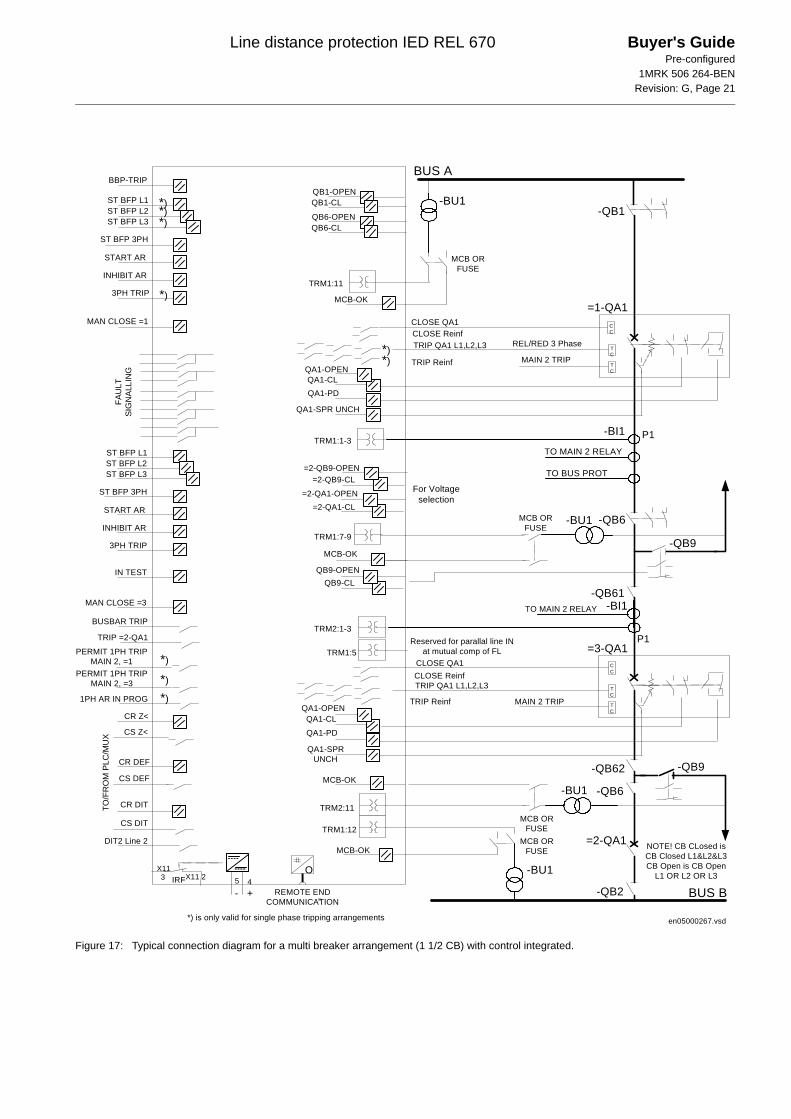
Figure 17: Typical connection diagram for a multi breaker arrangement (1 1/2 CB) with control integrated.
CC
TC
TC
=3-QA1
QA1-OPENQA1-CL
QA1-SPRUNCH
QA1-PD
CLOSE QA1
TRIP QA1 L1,L2,L3
MAIN 2 TRIP
CC
TC
TC
P1
-QB1
=1-QA1
-BI1
QB1-OPENQB1-CL
QB6-OPENQB6-CL
QA1-OPENQA1-CL
QA1-SPR UNCH
QA1-PD
CLOSE QA1
TRIP QA1 L1,L2,L3
MAIN 2 TRIP
-QB9
MCB-OK
MCB-OK
BUS A
BUS B
BBP-TRIP
ST BFP L1ST BFP L2ST BFP L3
ST BFP 3PH
START AR
INHIBIT AR
3PH TRIP
1PH AR IN PROG
CR Z<
CS Z<
CR DEF
CS DEF
CR DIT
CS DIT
TO/F
RO
M P
LC/M
UX
FAU
LTSI
GN
ALLI
NG
REMOTE ENDCOMMUNICATION
O
TO MAIN 2 RELAY
TO BUS PROT
MCB ORFUSE
MCB-OK
- +IRF
MAN CLOSE =1
P1
-BI1TO MAIN 2 RELAY
-QB9MCB-OK
MCB ORFUSE
-QB6
MCB ORFUSE
ST BFP L1ST BFP L2ST BFP L3
ST BFP 3PH
START AR
INHIBIT AR
3PH TRIP
BUSBAR TRIP
TRIP =2-QA1
DIT2 Line 2 =2-QA1
TRIP Reinf
CLOSE Reinf
TRIP Reinf
CLOSE Reinf
QB9-OPENQB9-CL
TRM1:1-3
TRM2:1-3
TRM1:7-9
TRM1:11
TRM2:11
TRM1:12
NOTE! CB CLosed isCB Closed L1&L2&L3CB Open is CB Open
L1 OR L2 OR L3
-BU1
-BU1
-BU1
-BU1
-QB61
-QB62
-QB6
-QB2
MCB ORFUSE
TRM1:5Reserved for parallal line IN
at mutual comp of FLPERMIT 1PH TRIPMAIN 2, =1
=2-QB9-OPEN=2-QB9-CL
=2-QA1-OPEN=2-QA1-CL
For Voltageselection
PERMIT 1PH TRIPMAIN 2, =3
IN TEST
MAN CLOSE =3
en05000267.vsd
*)*)*)
*)
*)
*)
*)
X11 2X113 5 4
*)*)
REL/RED 3 Phase
*) is only valid for single phase tripping arrangements
Line distance protection IED REL 670 Buyer's GuidePre-configured
1MRK 506 264-BENRevision: G, Page 22
Technical data General
Definitions
Energizing quantities, rated values and limits
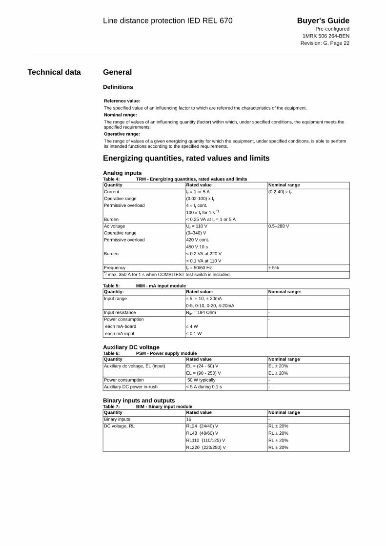
Analog inputsTable 4: TRM - Energizing quantities, rated values and limits
Table 5: MIM - mA input module
Auxiliary DC voltageTable 6: PSM - Power supply module
Binary inputs and outputsTable 7: BIM - Binary input module
Reference value:The specified value of an influencing factor to which are referred the characteristics of the equipment.Nominal range:The range of values of an influencing quantity (factor) within which, under specified conditions, the equipment meets the specified requirements.Operative range:The range of values of a given energizing quantity for which the equipment, under specified conditions, is able to perform its intended functions according to the specified requirements.
Quantity Rated value Nominal rangeCurrent Ir = 1 or 5 A (0.2-40) × IrOperative range (0.02-100) x IrPermissive overload 4 × Ir cont.
100 × Ir for 1 s *)
Burden < 0.25 VA at Ir = 1 or 5 AAc voltage Ur = 110 V 0.5–288 VOperative range (0–340) VPermissive overload 420 V cont.
450 V 10 sBurden < 0.2 VA at 220 V
< 0.1 VA at 110 VFrequency fr = 50/60 Hz ± 5%*) max. 350 A for 1 s when COMBITEST test switch is included.
Quantity: Rated value: Nominal range:Input range ± 5, ± 10, ± 20mA
0-5, 0-10, 0-20, 4-20mA-
Input resistance Rin = 194 Ohm -Power consumption each mA-board each mA input
≤ 4 W≤ 0.1 W
-
Quantity Rated value Nominal rangeAuxiliary dc voltage, EL (input) EL = (24 - 60) V
EL = (90 - 250) VEL ± 20%EL ± 20%
Power consumption 50 W typically -Auxiliary DC power in-rush < 5 A during 0.1 s -
Quantity Rated value Nominal rangeBinary inputs 16 -DC voltage, RL RL24 (24/40) V
RL48 (48/60) VRL110 (110/125) VRL220 (220/250) V
RL ± 20%RL ± 20%RL ± 20% RL ± 20%
Line distance protection IED REL 670 Buyer's GuidePre-configured
1MRK 506 264-BENRevision: G, Page 23
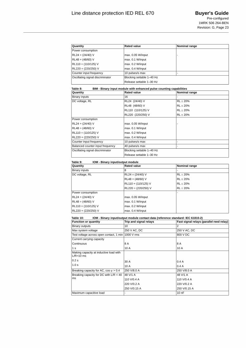
Table 8: BIM - Binary input module with enhanced pulse counting capabilities
Table 9: IOM - Binary input/output module
Table 10: IOM - Binary input/output module contact data (reference standard: IEC 61810-2)
Power consumptionRL24 = (24/40) VRL48 = (48/60) VRL110 = (110/125) VRL220 = (220/250) V
max. 0.05 W/inputmax. 0.1 W/inputmax. 0.2 W/inputmax. 0.4 W/input
-
Counter input frequency 10 pulses/s max -Oscillating signal discriminator Blocking settable 1–40 Hz
Release settable 1–30 Hz
Quantity Rated value Nominal rangeBinary inputs 16 -DC voltage, RL RL24 (24/40) V
RL48 (48/60) VRL110 (110/125) VRL220 (220/250) V
RL ± 20%RL ± 20%RL ± 20% RL ± 20%
Power consumptionRL24 = (24/40) VRL48 = (48/60) VRL110 = (110/125) VRL220 = (220/250) V
max. 0.05 W/inputmax. 0.1 W/inputmax. 0.2 W/inputmax. 0.4 W/input
-
Counter input frequency 10 pulses/s max -Balanced counter input frequency 40 pulses/s max -Oscillating signal discriminator Blocking settable 1–40 Hz
Release settable 1–30 Hz
Quantity Rated value Nominal rangeBinary inputs 8 -DC voltage, RL RL24 = (24/40) V
RL48 = (48/60) VRL110 = (110/125) VRL220 = (220/250) V
RL ± 20%RL ± 20%RL ± 20%RL ± 20%
Power consumptionRL24 = (24/40) VRL48 = (48/60) VRL110 = (110/125) VRL220 = (220/250) V
max. 0.05 W/inputmax. 0.1 W/inputmax. 0.2 W/inputmax. 0.4 W/input
-
Function or quantity Trip and signal relays Fast signal relays (parallel reed relay)Binary outputs 10 2Max system voltage 250 V AC, DC 250 V AC, DCTest voltage across open contact, 1 min 1000 V rms 800 V DCCurrent carrying capacityContinuous1 s
8 A10 A
8 A10 A
Making capacity at inductive load with L/R>10 ms0.2 s1.0 s
30 A10 A
0.4 A0.4 A
Breaking capacity for AC, cos ϕ > 0.4 250 V/8.0 A 250 V/8.0 ABreaking capacity for DC with L/R < 40 ms
48 V/1 A110 V/0.4 A220 V/0.2 A250 V/0.15 A
48 V/1 A110 V/0.4 A220 V/0.2 A250 V/0.15 A
Maximum capacitive load - 10 nF
Quantity Rated value Nominal range
Line distance protection IED REL 670 Buyer's GuidePre-configured
1MRK 506 264-BENRevision: G, Page 24
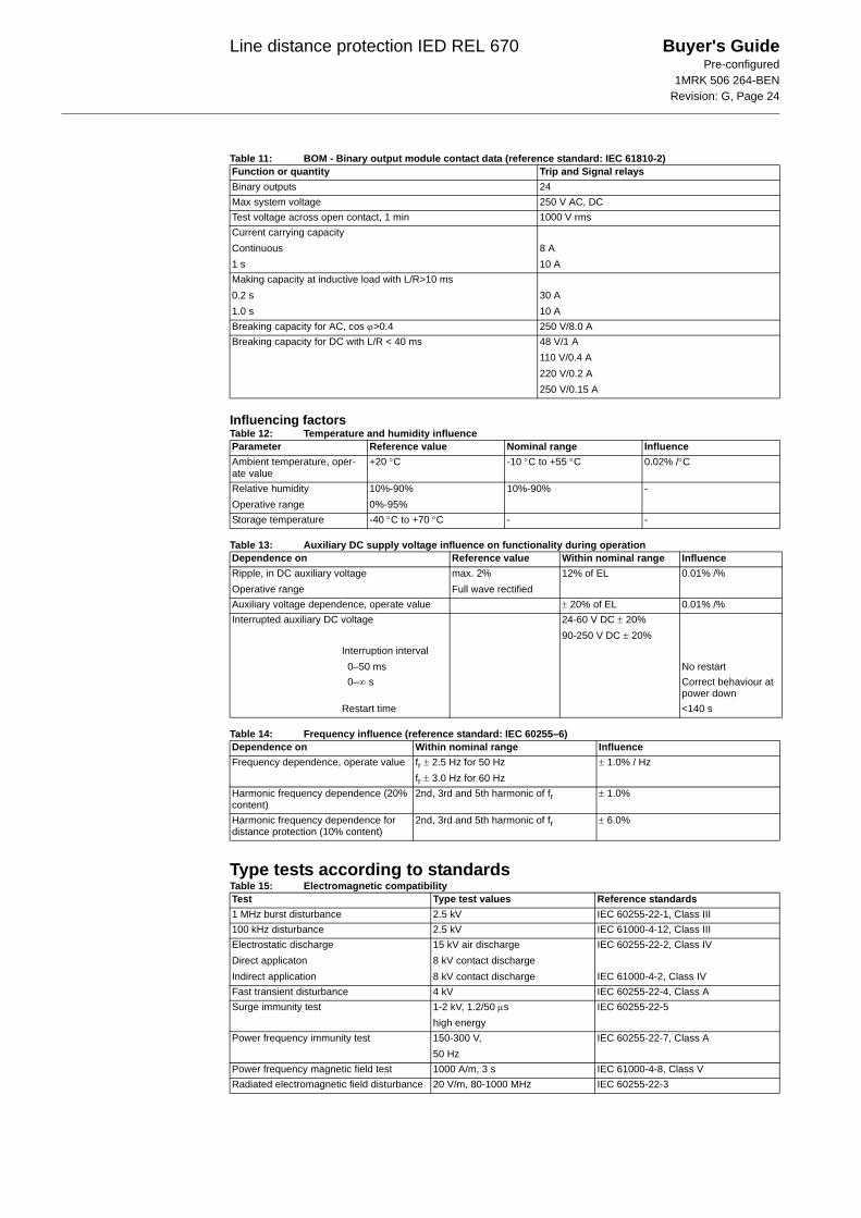
Table 11: BOM - Binary output module contact data (reference standard: IEC 61810-2)
Influencing factorsTable 12: Temperature and humidity influence
Table 13: Auxiliary DC supply voltage influence on functionality during operation
Table 14: Frequency influence (reference standard: IEC 60255–6)
Type tests according to standardsTable 15: Electromagnetic compatibility
Function or quantity Trip and Signal relaysBinary outputs 24Max system voltage 250 V AC, DCTest voltage across open contact, 1 min 1000 V rmsCurrent carrying capacityContinuous1 s
8 A10 A
Making capacity at inductive load with L/R>10 ms0.2 s1.0 s
30 A10 A
Breaking capacity for AC, cos ϕ>0.4 250 V/8.0 ABreaking capacity for DC with L/R < 40 ms 48 V/1 A
110 V/0.4 A220 V/0.2 A250 V/0.15 A
Parameter Reference value Nominal range InfluenceAmbient temperature, oper-ate value
+20 °C -10 °C to +55 °C 0.02% /°C
Relative humidityOperative range
10%-90%0%-95%
10%-90% -
Storage temperature -40 °C to +70 °C - -
Dependence on Reference value Within nominal range InfluenceRipple, in DC auxiliary voltageOperative range
max. 2%Full wave rectified
12% of EL 0.01% /%
Auxiliary voltage dependence, operate value ± 20% of EL 0.01% /%Interrupted auxiliary DC voltage 24-60 V DC ± 20%
90-250 V DC ± 20%Interruption interval
0–50 ms No restart0–∞ s Correct behaviour at
power downRestart time <140 s
Dependence on Within nominal range InfluenceFrequency dependence, operate value fr ± 2.5 Hz for 50 Hz
fr ± 3.0 Hz for 60 Hz± 1.0% / Hz
Harmonic frequency dependence (20% content)
2nd, 3rd and 5th harmonic of fr ± 1.0%
Harmonic frequency dependence for distance protection (10% content)
2nd, 3rd and 5th harmonic of fr ± 6.0%
Test Type test values Reference standards1 MHz burst disturbance 2.5 kV IEC 60255-22-1, Class III100 kHz disturbance 2.5 kV IEC 61000-4-12, Class IIIElectrostatic dischargeDirect applicatonIndirect application
15 kV air discharge8 kV contact discharge8 kV contact discharge
IEC 60255-22-2, Class IV
IEC 61000-4-2, Class IVFast transient disturbance 4 kV IEC 60255-22-4, Class ASurge immunity test 1-2 kV, 1.2/50 μs
high energyIEC 60255-22-5
Power frequency immunity test 150-300 V, 50 Hz
IEC 60255-22-7, Class A
Power frequency magnetic field test 1000 A/m, 3 s IEC 61000-4-8, Class VRadiated electromagnetic field disturbance 20 V/m, 80-1000 MHz IEC 60255-22-3
Line distance protection IED REL 670 Buyer's GuidePre-configured
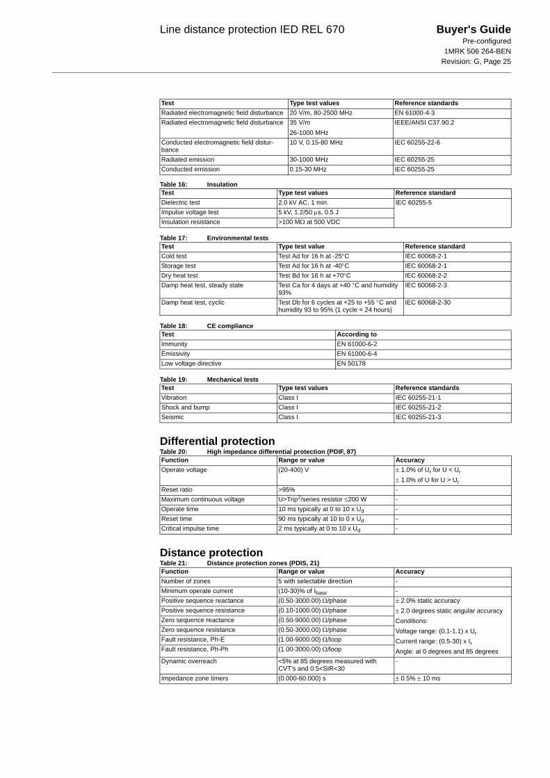
1MRK 506 264-BENRevision: G, Page 25
Table 16: Insulation
Table 17: Environmental tests
Table 18: CE compliance
Table 19: Mechanical tests
Differential protectionTable 20: High impedance differential protection (PDIF, 87)
Distance protectionTable 21: Distance protection zones (PDIS, 21)
Radiated electromagnetic field disturbance 20 V/m, 80-2500 MHz EN 61000-4-3Radiated electromagnetic field disturbance 35 V/m
26-1000 MHzIEEE/ANSI C37.90.2
Conducted electromagnetic field distur-bance
10 V, 0.15-80 MHz IEC 60255-22-6
Radiated emission 30-1000 MHz IEC 60255-25Conducted emission 0.15-30 MHz IEC 60255-25
Test Type test values Reference standardDielectric test 2.0 kV AC, 1 min. IEC 60255-5Impulse voltage test 5 kV, 1.2/50 μs, 0.5 JInsulation resistance >100 MΩ at 500 VDC
Test Type test value Reference standardCold test Test Ad for 16 h at -25°C IEC 60068-2-1Storage test Test Ad for 16 h at -40°C IEC 60068-2-1Dry heat test Test Bd for 16 h at +70°C IEC 60068-2-2Damp heat test, steady state Test Ca for 4 days at +40 °C and humidity
93%IEC 60068-2-3
Damp heat test, cyclic Test Db for 6 cycles at +25 to +55 °C and humidity 93 to 95% (1 cycle = 24 hours)
IEC 60068-2-30
Test According toImmunity EN 61000-6-2Emissivity EN 61000-6-4Low voltage directive EN 50178
Test Type test values Reference standardsVibration Class I IEC 60255-21-1Shock and bump Class I IEC 60255-21-2Seismic Class I IEC 60255-21-3
Function Range or value AccuracyOperate voltage (20-400) V ± 1.0% of Ur for U < Ur
± 1.0% of U for U > UrReset ratio >95% -Maximum continuous voltage U>Trip2/series resistor ≤200 W -Operate time 10 ms typically at 0 to 10 x Ud -Reset time 90 ms typically at 10 to 0 x Ud -Critical impulse time 2 ms typically at 0 to 10 x Ud -
Test Type test values Reference standards
Function Range or value AccuracyNumber of zones 5 with selectable direction -Minimum operate current (10-30)% of Ibase -Positive sequence reactance (0.50-3000.00) Ω/phase ± 2.0% static accuracy
± 2.0 degrees static angular accuracyConditions:Voltage range: (0.1-1.1) x UrCurrent range: (0.5-30) x IrAngle: at 0 degrees and 85 degrees
Positive sequence resistance (0.10-1000.00) Ω/phaseZero sequence reactance (0.50-9000.00) Ω/phaseZero sequence resistance (0.50-3000.00) Ω/phaseFault resistance, Ph-E (1.00-9000.00) Ω/loopFault resistance, Ph-Ph (1.00-3000.00) Ω/loop
Dynamic overreach <5% at 85 degrees measured with CVT’s and 0.5<SIR<30
-
Impedance zone timers (0.000-60.000) s ± 0.5% ± 10 ms
Line distance protection IED REL 670 Buyer's GuidePre-configured
1MRK 506 264-BENRevision: G, Page 26
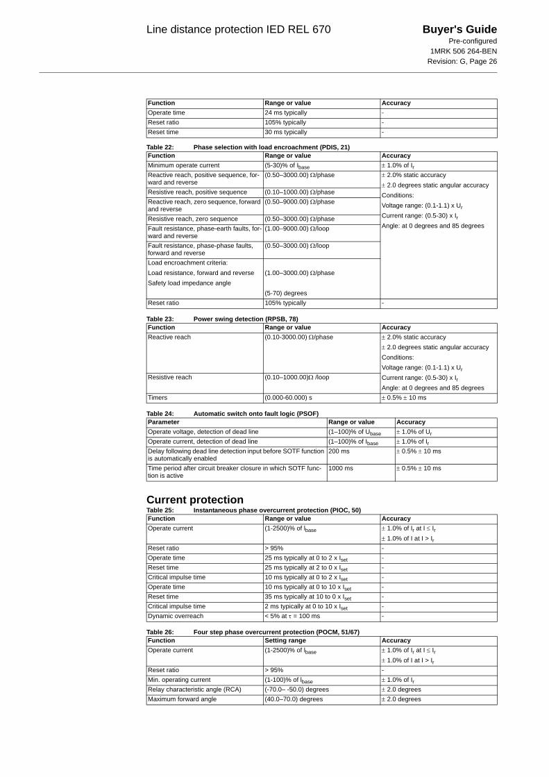
Table 22: Phase selection with load encroachment (PDIS, 21)
Table 23: Power swing detection (RPSB, 78)
Table 24: Automatic switch onto fault logic (PSOF)
Current protectionTable 25: Instantaneous phase overcurrent protection (PIOC, 50)
Table 26: Four step phase overcurrent protection (POCM, 51/67)
Operate time 24 ms typically -Reset ratio 105% typically -Reset time 30 ms typically -
Function Range or value AccuracyMinimum operate current (5-30)% of Ibase ± 1.0% of IrReactive reach, positive sequence, for-ward and reverse
(0.50–3000.00) Ω/phase ± 2.0% static accuracy± 2.0 degrees static angular accuracyConditions:Voltage range: (0.1-1.1) x UrCurrent range: (0.5-30) x IrAngle: at 0 degrees and 85 degrees
Resistive reach, positive sequence (0.10–1000.00) Ω/phaseReactive reach, zero sequence, forward and reverse
(0.50–9000.00) Ω/phase
Resistive reach, zero sequence (0.50–3000.00) Ω/phaseFault resistance, phase-earth faults, for-ward and reverse
(1.00–9000.00) Ω/loop
Fault resistance, phase-phase faults, forward and reverse
(0.50–3000.00) Ω/loop
Load encroachment criteria:Load resistance, forward and reverseSafety load impedance angle
(1.00–3000.00) Ω/phase
(5-70) degreesReset ratio 105% typically -
Function Range or value AccuracyReactive reach (0.10-3000.00) Ω/phase ± 2.0% static accuracy
± 2.0 degrees static angular accuracyConditions:Voltage range: (0.1-1.1) x UrCurrent range: (0.5-30) x IrAngle: at 0 degrees and 85 degrees
Resistive reach (0.10–1000.00)Ω /loop
Timers (0.000-60.000) s ± 0.5% ± 10 ms
Parameter Range or value AccuracyOperate voltage, detection of dead line (1–100)% of Ubase ± 1.0% of UrOperate current, detection of dead line (1–100)% of Ibase ± 1.0% of IrDelay following dead line detection input before SOTF function is automatically enabled
200 ms ± 0.5% ± 10 ms
Time period after circuit breaker closure in which SOTF func-tion is active
1000 ms ± 0.5% ± 10 ms
Function Range or value Accuracy
Function Range or value AccuracyOperate current (1-2500)% of lbase ± 1.0% of Ir at I ≤ Ir
± 1.0% of I at I > IrReset ratio > 95% -Operate time 25 ms typically at 0 to 2 x Iset -Reset time 25 ms typically at 2 to 0 x Iset -Critical impulse time 10 ms typically at 0 to 2 x Iset -Operate time 10 ms typically at 0 to 10 x Iset -Reset time 35 ms typically at 10 to 0 x Iset -Critical impulse time 2 ms typically at 0 to 10 x Iset -Dynamic overreach < 5% at τ = 100 ms -
Function Setting range AccuracyOperate current (1-2500)% of lbase ± 1.0% of Ir at I ≤ Ir
± 1.0% of I at I > IrReset ratio > 95% -Min. operating current (1-100)% of lbase ± 1.0% of IrRelay characteristic angle (RCA) (-70.0– -50.0) degrees ± 2.0 degreesMaximum forward angle (40.0–70.0) degrees ± 2.0 degrees
Line distance protection IED REL 670 Buyer's GuidePre-configured
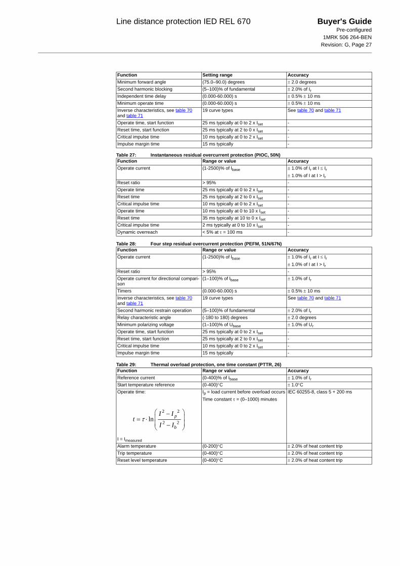
1MRK 506 264-BENRevision: G, Page 27
Table 27: Instantaneous residual overcurrent protection (PIOC, 50N)
Table 28: Four step residual overcurrent protection (PEFM, 51N/67N)
Table 29: Thermal overload protection, one time constant (PTTR, 26)
Minimum forward angle (75.0–90.0) degrees ± 2.0 degreesSecond harmonic blocking (5–100)% of fundamental ± 2.0% of IrIndependent time delay (0.000-60.000) s ± 0.5% ± 10 msMinimum operate time (0.000-60.000) s ± 0.5% ± 10 msInverse characteristics, see table 70 and table 71
19 curve types See table 70 and table 71
Operate time, start function 25 ms typically at 0 to 2 x Iset -Reset time, start function 25 ms typically at 2 to 0 x Iset -Critical impulse time 10 ms typically at 0 to 2 x Iset -Impulse margin time 15 ms typically -
Function Range or value AccuracyOperate current (1-2500)% of lbase ± 1.0% of Ir at I ≤ Ir
± 1.0% of I at I > IrReset ratio > 95% -Operate time 25 ms typically at 0 to 2 x Iset -Reset time 25 ms typically at 2 to 0 x Iset -Critical impulse time 10 ms typically at 0 to 2 x Iset -Operate time 10 ms typically at 0 to 10 x Iset -Reset time 35 ms typically at 10 to 0 x Iset -Critical impulse time 2 ms typically at 0 to 10 x Iset -Dynamic overreach < 5% at τ = 100 ms -
Function Range or value AccuracyOperate current (1-2500)% of lbase ± 1.0% of Ir at I ≤ Ir
± 1.0% of I at I > IrReset ratio > 95% -Operate current for directional compari-son
(1–100)% of lbase ± 1.0% of Ir
Timers (0.000-60.000) s ± 0.5% ± 10 msInverse characteristics, see table 70 and table 71
19 curve types See table 70 and table 71
Second harmonic restrain operation (5–100)% of fundamental ± 2.0% of IrRelay characteristic angle (-180 to 180) degrees ± 2.0 degreesMinimum polarizing voltage (1–100)% of Ubase ± 1.0% of UrOperate time, start function 25 ms typically at 0 to 2 x Iset -Reset time, start function 25 ms typically at 2 to 0 x Iset -Critical impulse time 10 ms typically at 0 to 2 x Iset -Impulse margin time 15 ms typically -
Function Range or value AccuracyReference current (0-400)% of Ibase ± 1.0% of IrStart temperature reference (0-400)°C ± 1.0°COperate time:
I = Imeasured
Ip = load current before overload occursTime constant τ = (0–1000) minutes
IEC 60255-8, class 5 + 200 ms
Alarm temperature (0-200)°C ± 2.0% of heat content tripTrip temperature (0-400)°C ± 2.0% of heat content tripReset level temperature (0-400)°C ± 2.0% of heat content trip
Function Setting range Accuracy
2 2
2 2ln p
b
I It
I Iτ
⎛ ⎞−⎜ ⎟= ⋅⎜ ⎟−⎝ ⎠
Line distance protection IED REL 670 Buyer's GuidePre-configured
1MRK 506 264-BENRevision: G, Page 28
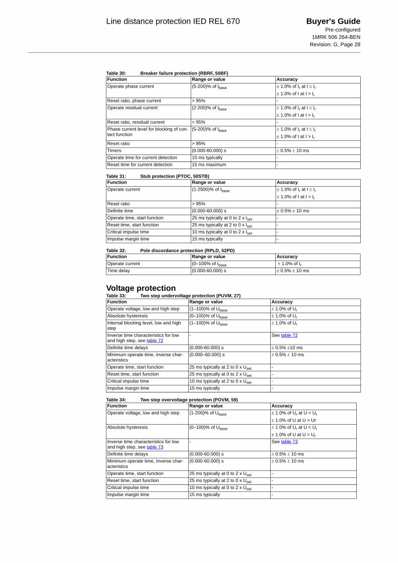
Table 30: Breaker failure protection (RBRF, 50BF)
Table 31: Stub protection (PTOC, 50STB)
Table 32: Pole discordance protection (RPLD, 52PD)
Voltage protectionTable 33: Two step undervoltage protection (PUVM, 27)
Table 34: Two step overvoltage protection (POVM, 59)
Function Range or value AccuracyOperate phase current (5-200)% of lbase ± 1.0% of Ir at I ≤ Ir
± 1.0% of I at I > IrReset ratio, phase current > 95% -Operate residual current (2-200)% of lbase ± 1.0% of Ir at I ≤ Ir
± 1.0% of I at I > IrReset ratio, residual current > 95% -Phase current level for blocking of con-tact function
(5-200)% of lbase ± 1.0% of Ir at I ≤ Ir± 1.0% of I at I > Ir
Reset ratio > 95% -Timers (0.000-60.000) s ± 0.5% ± 10 msOperate time for current detection 10 ms typically -Reset time for current detection 15 ms maximum -
Function Range or value AccuracyOperate current (1-2500)% of Ibase ± 1.0% of Ir at I ≤ Ir
± 1.0% of I at I > IrReset ratio > 95% -Definite time (0.000-60.000) s ± 0.5% ± 10 msOperate time, start function 25 ms typically at 0 to 2 x Iset -Reset time, start function 25 ms typically at 2 to 0 x Iset -Critical impulse time 10 ms typically at 0 to 2 x Iset -Impulse margin time 15 ms typically -
Function Range or value AccuracyOperate current (0–100% of Ibase ± 1.0% of IrTime delay (0.000-60.000) s ± 0.5% ± 10 ms
Function Range or value AccuracyOperate voltage, low and high step (1–100)% of Ubase ± 1.0% of UrAbsolute hysteresis (0–100)% of Ubase ± 1.0% of UrInternal blocking level, low and high step
(1–100)% of Ubase ± 1.0% of Ur
Inverse time characteristics for low and high step, see table 72
- See table 72
Definite time delays (0.000-60.000) s ± 0.5% ±10 msMinimum operate time, inverse char-acteristics
(0.000–60.000) s ± 0.5% ± 10 ms
Operate time, start function 25 ms typically at 2 to 0 x Uset -Reset time, start function 25 ms typically at 0 to 2 x Uset -Critical impulse time 10 ms typically at 2 to 0 x Uset -Impulse margin time 15 ms typically -
Function Range or value AccuracyOperate voltage, low and high step (1-200)% of Ubase ± 1.0% of Ur at U < Ur
± 1.0% of U at U > UrAbsolute hysteresis (0–100)% of Ubase ± 1.0% of Ur at U < Ur
± 1.0% of U at U > UrInverse time characteristics for low and high step, see table 73
- See table 73
Definite time delays (0.000-60.000) s ± 0.5% ± 10 msMinimum operate time, Inverse char-acteristics
(0.000-60.000) s ± 0.5% ± 10 ms
Operate time, start function 25 ms typically at 0 to 2 x Uset -Reset time, start function 25 ms typically at 2 to 0 x Uset -Critical impulse time 10 ms typically at 0 to 2 x Uset -Impulse margin time 15 ms typically -
Line distance protection IED REL 670 Buyer's GuidePre-configured
1MRK 506 264-BENRevision: G, Page 29
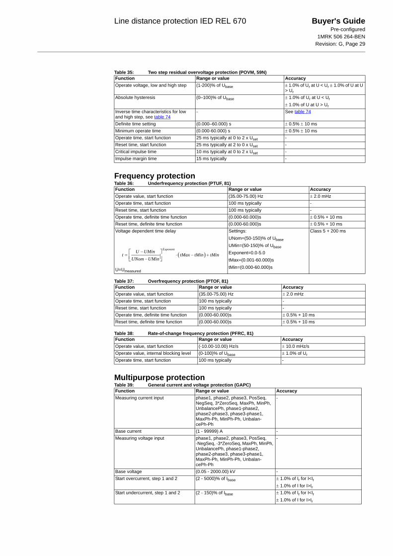
Table 35: Two step residual overvoltage protection (POVM, 59N)
Frequency protectionTable 36: Underfrequency protection (PTUF, 81)
Table 37: Overfrequency protection (PTOF, 81)
Table 38: Rate-of-change frequency protection (PFRC, 81)
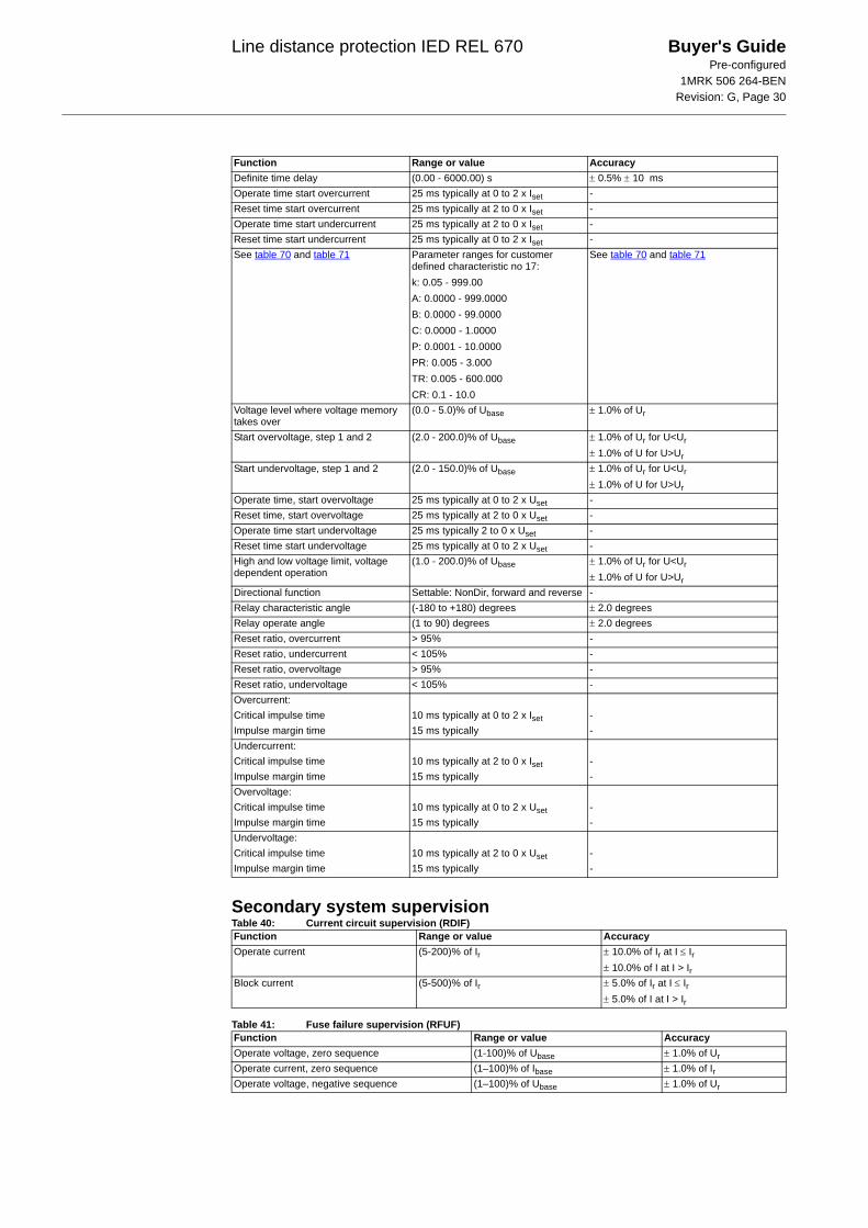
Multipurpose protectionTable 39: General current and voltage protection (GAPC)
Function Range or value AccuracyOperate voltage, low and high step (1-200)% of Ubase ± 1.0% of Ur at U < Ur ± 1.0% of U at U
> UrAbsolute hysteresis (0–100)% of Ubase ± 1.0% of Ur at U < Ur
± 1.0% of U at U > UrInverse time characteristics for low and high step, see table 74
- See table 74
Definite time setting (0.000–60.000) s ± 0.5% ± 10 msMinimum operate time (0.000-60.000) s ± 0.5% ± 10 msOperate time, start function 25 ms typically at 0 to 2 x Uset -Reset time, start function 25 ms typically at 2 to 0 x Uset -Critical impulse time 10 ms typically at 0 to 2 x Uset -Impulse margin time 15 ms typically -
Function Range or value AccuracyOperate value, start function (35.00-75.00) Hz ± 2.0 mHz Operate time, start function 100 ms typically -Reset time, start function 100 ms typically -Operate time, definite time function (0.000-60.000)s ± 0.5% + 10 msReset time, definite time function (0.000-60.000)s ± 0.5% + 10 msVoltage dependent time delay
U=Umeasured
Settings:UNom=(50-150)% of UbaseUMin=(50-150)% of UbaseExponent=0.0-5.0tMax=(0.001-60.000)stMin=(0.000-60.000)s
Class 5 + 200 ms
Function Range or value AccuracyOperate value, start function (35.00-75.00) Hz ± 2.0 mHz Operate time, start function 100 ms typically -Reset time, start function 100 ms typically -Operate time, definite time function (0.000-60.000)s ± 0.5% + 10 msReset time, definite time function (0.000-60.000)s ± 0.5% + 10 ms
Function Range or value AccuracyOperate value, start function (-10.00-10.00) Hz/s ± 10.0 mHz/s Operate value, internal blocking level (0-100)% of Ubase ± 1.0% of UrOperate time, start function 100 ms typically -
( )ExponentU UMin
t tMax tMin tMinUNom UMin
−= ⋅ − +
−⎡ ⎤⎢ ⎥⎣ ⎦
Function Range or value AccuracyMeasuring current input phase1, phase2, phase3, PosSeq,
NegSeq, 3*ZeroSeq, MaxPh, MinPh, UnbalancePh, phase1-phase2, phase2-phase3, phase3-phase1, MaxPh-Ph, MinPh-Ph, Unbalan-cePh-Ph
-
Base current (1 - 99999) A -Measuring voltage input phase1, phase2, phase3, PosSeq,
-NegSeq, -3*ZeroSeq, MaxPh, MinPh, UnbalancePh, phase1-phase2, phase2-phase3, phase3-phase1, MaxPh-Ph, MinPh-Ph, Unbalan-cePh-Ph
-
Base voltage (0.05 - 2000.00) kV -Start overcurrent, step 1 and 2 (2 - 5000)% of Ibase ± 1.0% of Ir for I<Ir
± 1.0% of I for I>IrStart undercurrent, step 1 and 2 (2 - 150)% of Ibase ± 1.0% of Ir for I<Ir
± 1.0% of I for I>Ir
Line distance protection IED REL 670 Buyer's GuidePre-configured
1MRK 506 264-BENRevision: G, Page 30
Secondary system supervisionTable 40: Current circuit supervision (RDIF)
Table 41: Fuse failure supervision (RFUF)
Definite time delay (0.00 - 6000.00) s ± 0.5% ± 10 msOperate time start overcurrent 25 ms typically at 0 to 2 x Iset -Reset time start overcurrent 25 ms typically at 2 to 0 x Iset -Operate time start undercurrent 25 ms typically at 2 to 0 x Iset -Reset time start undercurrent 25 ms typically at 0 to 2 x Iset -See table 70 and table 71 Parameter ranges for customer
defined characteristic no 17:k: 0.05 - 999.00A: 0.0000 - 999.0000B: 0.0000 - 99.0000C: 0.0000 - 1.0000P: 0.0001 - 10.0000PR: 0.005 - 3.000TR: 0.005 - 600.000CR: 0.1 - 10.0
See table 70 and table 71
Voltage level where voltage memory takes over
(0.0 - 5.0)% of Ubase ± 1.0% of Ur
Start overvoltage, step 1 and 2 (2.0 - 200.0)% of Ubase ± 1.0% of Ur for U<Ur± 1.0% of U for U>Ur
Start undervoltage, step 1 and 2 (2.0 - 150.0)% of Ubase ± 1.0% of Ur for U<Ur± 1.0% of U for U>Ur
Operate time, start overvoltage 25 ms typically at 0 to 2 x Uset -Reset time, start overvoltage 25 ms typically at 2 to 0 x Uset -Operate time start undervoltage 25 ms typically 2 to 0 x Uset -Reset time start undervoltage 25 ms typically at 0 to 2 x Uset -High and low voltage limit, voltage dependent operation
(1.0 - 200.0)% of Ubase ± 1.0% of Ur for U<Ur± 1.0% of U for U>Ur
Directional function Settable: NonDir, forward and reverse -Relay characteristic angle (-180 to +180) degrees ± 2.0 degreesRelay operate angle (1 to 90) degrees ± 2.0 degreesReset ratio, overcurrent > 95% -Reset ratio, undercurrent < 105% -Reset ratio, overvoltage > 95% -Reset ratio, undervoltage < 105% -Overcurrent:Critical impulse time 10 ms typically at 0 to 2 x Iset -Impulse margin time 15 ms typically -Undercurrent:Critical impulse time 10 ms typically at 2 to 0 x Iset -Impulse margin time 15 ms typically -Overvoltage:Critical impulse time 10 ms typically at 0 to 2 x Uset -Impulse margin time 15 ms typically -Undervoltage:Critical impulse time 10 ms typically at 2 to 0 x Uset -Impulse margin time 15 ms typically -
Function Range or value Accuracy
Function Range or value AccuracyOperate current (5-200)% of Ir ± 10.0% of Ir at I ≤ Ir
± 10.0% of I at I > IrBlock current (5-500)% of Ir ± 5.0% of Ir at I ≤ Ir
± 5.0% of I at I > Ir
Function Range or value AccuracyOperate voltage, zero sequence (1-100)% of Ubase ± 1.0% of UrOperate current, zero sequence (1–100)% of Ibase ± 1.0% of IrOperate voltage, negative sequence (1–100)% of Ubase ± 1.0% of Ur
Line distance protection IED REL 670 Buyer's GuidePre-configured
1MRK 506 264-BENRevision: G, Page 31
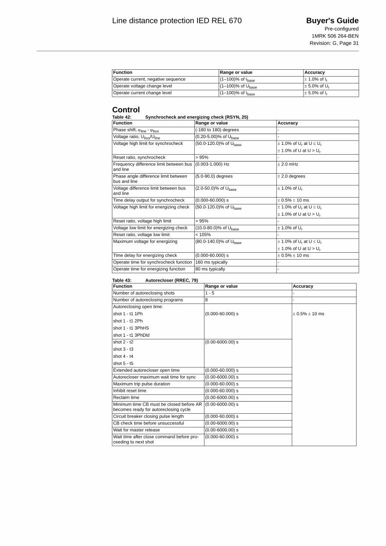
ControlTable 42: Synchrocheck and energizing check (RSYN, 25)
Table 43: Autorecloser (RREC, 79)
Operate current, negative sequence (1–100)% of Ibase ± 1.0% of IrOperate voltage change level (1–100)% of Ubase ± 5.0% of UrOperate current change level (1–100)% of Ibase ± 5.0% of Ir
Function Range or value Accuracy
Function Range or value AccuracyPhase shift, ϕline - ϕbus (-180 to 180) degrees -Voltage ratio, Ubus/Uline (0.20-5.00)% of Ubase -Voltage high limit for synchrocheck (50.0-120.0)% of Ubase ± 1.0% of Ur at U ≤ Ur
± 1.0% of U at U > UrReset ratio, synchrocheck > 95% -Frequency difference limit between bus and line
(0.003-1.000) Hz ± 2.0 mHz
Phase angle difference limit between bus and line
(5.0-90.0) degrees ± 2.0 degrees
Voltage difference limit between bus and line
(2.0-50.0)% of Ubase ± 1.0% of Ur
Time delay output for synchrocheck (0.000-60.000) s ± 0.5% ± 10 msVoltage high limit for energizing check (50.0-120.0)% of Ubase ± 1.0% of Ur at U ≤ Ur
± 1.0% of U at U > UrReset ratio, voltage high limit > 95% -Voltage low limit for energizing check (10.0-80.0)% of Ubase ± 1.0% of UrReset ratio, voltage low limit < 105% -Maximum voltage for energizing (80.0-140.0)% of Ubase ± 1.0% of Ur at U ≤ Ur
± 1.0% of U at U > UrTime delay for energizing check (0.000-60.000) s ± 0.5% ± 10 msOperate time for synchrocheck function 160 ms typically -Operate time for energizing function 80 ms typically -
Function Range or value AccuracyNumber of autoreclosing shots 1 - 5 -Number of autoreclosing programs 8 -Autoreclosing open time:shot 1 - t1 1Phshot 1 - t1 2Phshot 1 - t1 3PhHSshot 1 - t1 3PhDld
(0.000-60.000) s ± 0.5% ± 10 ms
shot 2 - t2shot 3 - t3shot 4 - t4shot 5 - t5
(0.00-6000.00) s
Extended autorecloser open time (0.000-60.000) sAutorecloser maximum wait time for sync (0.00-6000.00) sMaximum trip pulse duration (0.000-60.000) sInhibit reset time (0.000-60.000) sReclaim time (0.00-6000.00) sMinimum time CB must be closed before AR becomes ready for autoreclosing cycle
(0.00-6000.00) s
Circuit breaker closing pulse length (0.000-60.000) sCB check time before unsuccessful (0.00-6000.00) sWait for master release (0.00-6000.00) sWait time after close command before pro-ceeding to next shot
(0.000-60.000) s
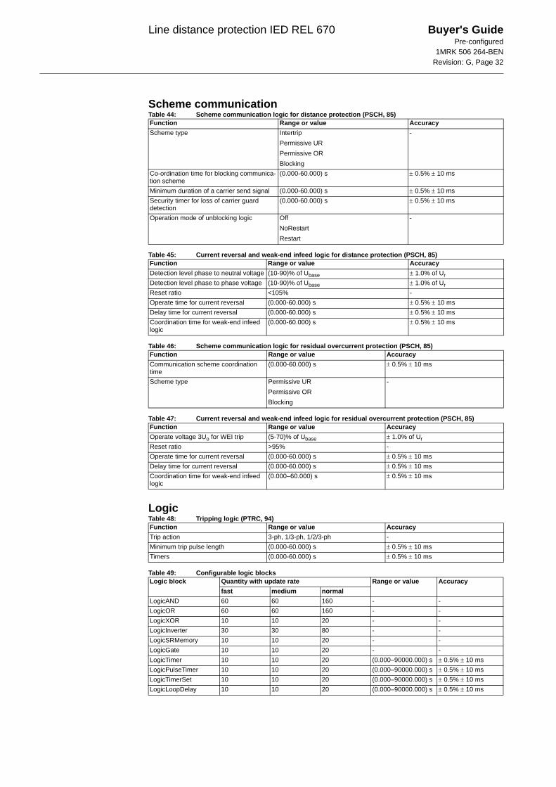
Line distance protection IED REL 670 Buyer's GuidePre-configured
1MRK 506 264-BENRevision: G, Page 32
Scheme communicationTable 44: Scheme communication logic for distance protection (PSCH, 85)
Table 45: Current reversal and weak-end infeed logic for distance protection (PSCH, 85)
Table 46: Scheme communication logic for residual overcurrent protection (PSCH, 85)
Table 47: Current reversal and weak-end infeed logic for residual overcurrent protection (PSCH, 85)
LogicTable 48: Tripping logic (PTRC, 94)
Table 49: Configurable logic blocks
Function Range or value AccuracyScheme type Intertrip
Permissive URPermissive ORBlocking
-
Co-ordination time for blocking communica-tion scheme
(0.000-60.000) s ± 0.5% ± 10 ms
Minimum duration of a carrier send signal (0.000-60.000) s ± 0.5% ± 10 msSecurity timer for loss of carrier guard detection
(0.000-60.000) s ± 0.5% ± 10 ms
Operation mode of unblocking logic OffNoRestartRestart
-
Function Range or value AccuracyDetection level phase to neutral voltage (10-90)% of Ubase ± 1.0% of UrDetection level phase to phase voltage (10-90)% of Ubase ± 1.0% of UrReset ratio <105% -Operate time for current reversal (0.000-60.000) s ± 0.5% ± 10 msDelay time for current reversal (0.000-60.000) s ± 0.5% ± 10 msCoordination time for weak-end infeed logic
(0.000-60.000) s ± 0.5% ± 10 ms
Function Range or value AccuracyCommunication scheme coordination time
(0.000-60.000) s ± 0.5% ± 10 ms
Scheme type Permissive URPermissive ORBlocking
-
Function Range or value AccuracyOperate voltage 3Uo for WEI trip (5-70)% of Ubase ± 1.0% of UrReset ratio >95% -Operate time for current reversal (0.000-60.000) s ± 0.5% ± 10 msDelay time for current reversal (0.000-60.000) s ± 0.5% ± 10 msCoordination time for weak-end infeed logic
(0.000–60.000) s ± 0.5% ± 10 ms
Function Range or value AccuracyTrip action 3-ph, 1/3-ph, 1/2/3-ph -Minimum trip pulse length (0.000-60.000) s ± 0.5% ± 10 msTimers (0.000-60.000) s ± 0.5% ± 10 ms
Logic block Quantity with update rate Range or value Accuracyfast medium normal
LogicAND 60 60 160 - -LogicOR 60 60 160 - -LogicXOR 10 10 20 - -LogicInverter 30 30 80 - -LogicSRMemory 10 10 20 - -LogicGate 10 10 20 - -LogicTimer 10 10 20 (0.000–90000.000) s ± 0.5% ± 10 msLogicPulseTimer 10 10 20 (0.000–90000.000) s ± 0.5% ± 10 msLogicTimerSet 10 10 20 (0.000–90000.000) s ± 0.5% ± 10 msLogicLoopDelay 10 10 20 (0.000–90000.000) s ± 0.5% ± 10 ms
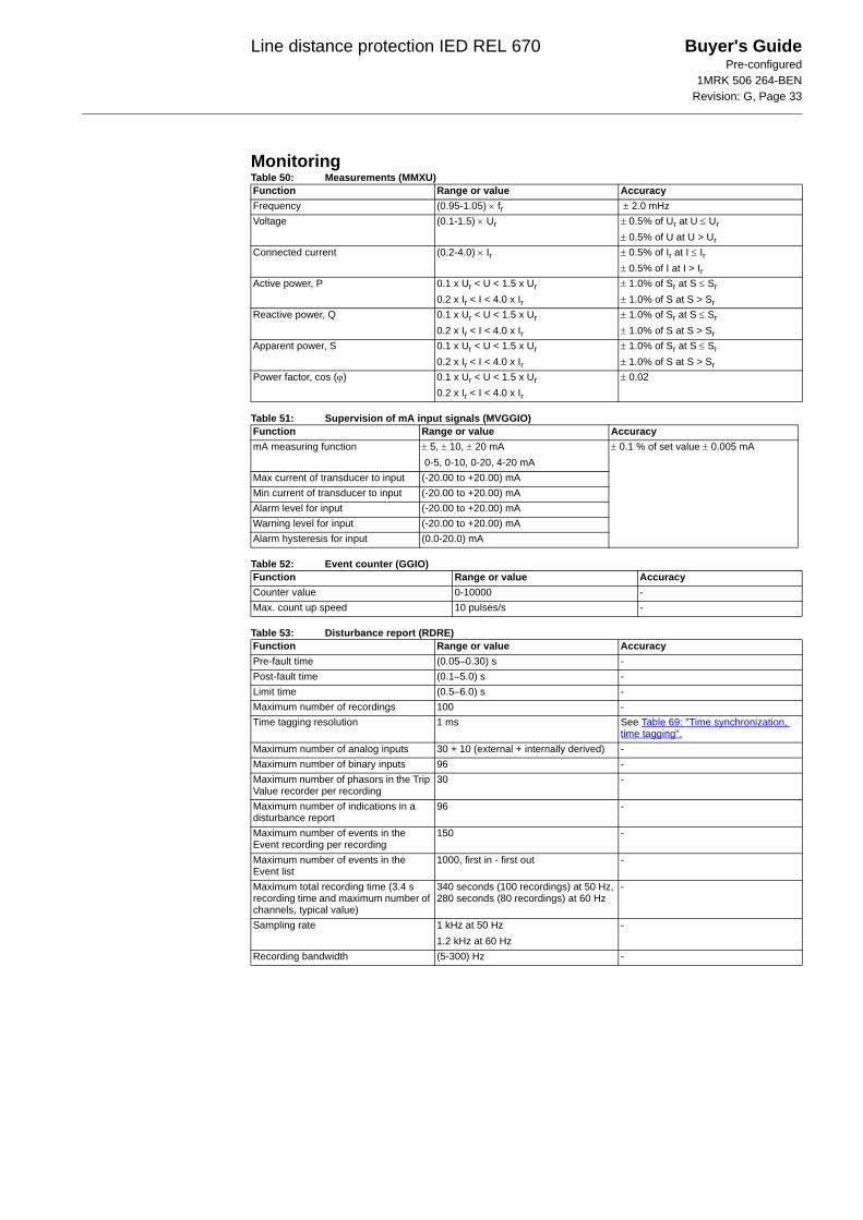
Line distance protection IED REL 670 Buyer's GuidePre-configured
1MRK 506 264-BENRevision: G, Page 33
MonitoringTable 50: Measurements (MMXU)
Table 51: Supervision of mA input signals (MVGGIO)
Table 52: Event counter (GGIO)
Table 53: Disturbance report (RDRE)
Function Range or value AccuracyFrequency (0.95-1.05) × fr ± 2.0 mHzVoltage (0.1-1.5) × Ur ± 0.5% of Ur at U ≤ Ur
± 0.5% of U at U > UrConnected current (0.2-4.0) × Ir ± 0.5% of Ir at I ≤ Ir
± 0.5% of I at I > IrActive power, P 0.1 x Ur < U < 1.5 x Ur
0.2 x Ir < I < 4.0 x Ir
± 1.0% of Sr at S ≤ Sr± 1.0% of S at S > Sr
Reactive power, Q 0.1 x Ur < U < 1.5 x Ur
0.2 x Ir < I < 4.0 x Ir
± 1.0% of Sr at S ≤ Sr
± 1.0% of S at S > SrApparent power, S 0.1 x Ur < U < 1.5 x Ur
0.2 x Ir < I < 4.0 x Ir
± 1.0% of Sr at S ≤ Sr± 1.0% of S at S > Sr
Power factor, cos (ϕ) 0.1 x Ur < U < 1.5 x Ur0.2 x Ir < I < 4.0 x Ir
± 0.02
Function Range or value AccuracymA measuring function ± 5, ± 10, ± 20 mA
0-5, 0-10, 0-20, 4-20 mA± 0.1 % of set value ± 0.005 mA
Max current of transducer to input (-20.00 to +20.00) mAMin current of transducer to input (-20.00 to +20.00) mAAlarm level for input (-20.00 to +20.00) mAWarning level for input (-20.00 to +20.00) mAAlarm hysteresis for input (0.0-20.0) mA
Function Range or value AccuracyCounter value 0-10000 -Max. count up speed 10 pulses/s -
Function Range or value AccuracyPre-fault time (0.05–0.30) s -Post-fault time (0.1–5.0) s -Limit time (0.5–6.0) s -Maximum number of recordings 100 -Time tagging resolution 1 ms See Table 69: "Time synchronization,
time tagging".Maximum number of analog inputs 30 + 10 (external + internally derived) -Maximum number of binary inputs 96 -Maximum number of phasors in the Trip Value recorder per recording
30 -
Maximum number of indications in a disturbance report
96 -
Maximum number of events in the Event recording per recording
150 -
Maximum number of events in the Event list
1000, first in - first out -
Maximum total recording time (3.4 s recording time and maximum number of channels, typical value)
340 seconds (100 recordings) at 50 Hz, 280 seconds (80 recordings) at 60 Hz
-
Sampling rate 1 kHz at 50 Hz1.2 kHz at 60 Hz
-
Recording bandwidth (5-300) Hz -
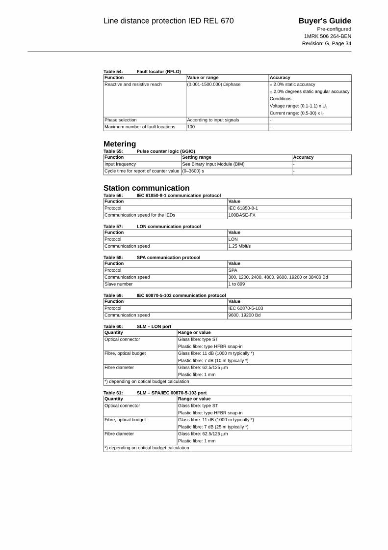
Line distance protection IED REL 670 Buyer's GuidePre-configured
1MRK 506 264-BENRevision: G, Page 34
Table 54: Fault locator (RFLO)
MeteringTable 55: Pulse counter logic (GGIO)
Station communicationTable 56: IEC 61850-8-1 communication protocol
Table 57: LON communication protocol
Table 58: SPA communication protocol
Table 59: IEC 60870-5-103 communication protocol
Table 60: SLM – LON port
Table 61: SLM – SPA/IEC 60870-5-103 port
Function Value or range AccuracyReactive and resistive reach (0.001-1500.000) Ω/phase ± 2.0% static accuracy
± 2.0% degrees static angular accuracyConditions:Voltage range: (0.1-1.1) x UrCurrent range: (0.5-30) x Ir
Phase selection According to input signals -Maximum number of fault locations 100 -
Function Setting range AccuracyInput frequency See Binary Input Module (BIM) -Cycle time for report of counter value (0–3600) s -
Function ValueProtocol IEC 61850-8-1Communication speed for the IEDs 100BASE-FX
Function ValueProtocol LONCommunication speed 1.25 Mbit/s
Function ValueProtocol SPACommunication speed 300, 1200, 2400, 4800, 9600, 19200 or 38400 BdSlave number 1 to 899
Function ValueProtocol IEC 60870-5-103Communication speed 9600, 19200 Bd
Quantity Range or valueOptical connector Glass fibre: type ST
Plastic fibre: type HFBR snap-inFibre, optical budget Glass fibre: 11 dB (1000 m typically *)
Plastic fibre: 7 dB (10 m typically *)Fibre diameter Glass fibre: 62.5/125 μm
Plastic fibre: 1 mm*) depending on optical budget calculation
Quantity Range or valueOptical connector Glass fibre: type ST
Plastic fibre: type HFBR snap-inFibre, optical budget Glass fibre: 11 dB (1000 m typically *)
Plastic fibre: 7 dB (25 m typically *)Fibre diameter Glass fibre: 62.5/125 μm
Plastic fibre: 1 mm*) depending on optical budget calculation
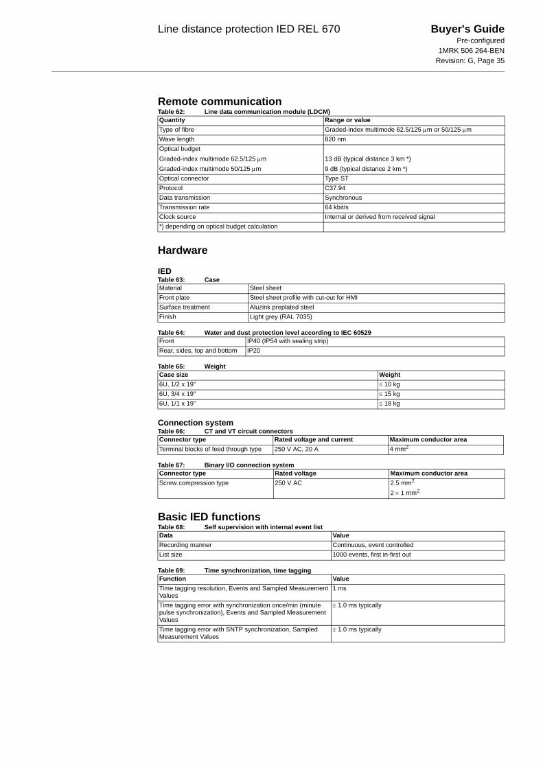
Line distance protection IED REL 670 Buyer's GuidePre-configured
1MRK 506 264-BENRevision: G, Page 35
Remote communicationTable 62: Line data communication module (LDCM)
Hardware
IEDTable 63: Case
Table 64: Water and dust protection level according to IEC 60529
Table 65: Weight
Connection systemTable 66: CT and VT circuit connectors
Table 67: Binary I/O connection system
Basic IED functionsTable 68: Self supervision with internal event list
Table 69: Time synchronization, time tagging
Quantity Range or valueType of fibre Graded-index multimode 62.5/125 μm or 50/125 μmWave length 820 nmOptical budgetGraded-index multimode 62.5/125 μmGraded-index multimode 50/125 μm
13 dB (typical distance 3 km *)9 dB (typical distance 2 km *)
Optical connector Type STProtocol C37.94Data transmission SynchronousTransmission rate 64 kbit/sClock source Internal or derived from received signal*) depending on optical budget calculation
Material Steel sheetFront plate Steel sheet profile with cut-out for HMISurface treatment Aluzink preplated steelFinish Light grey (RAL 7035)
Front IP40 (IP54 with sealing strip)Rear, sides, top and bottom IP20
Case size Weight6U, 1/2 x 19” ≤ 10 kg6U, 3/4 x 19” ≤ 15 kg6U, 1/1 x 19” ≤ 18 kg
Connector type Rated voltage and current Maximum conductor areaTerminal blocks of feed through type 250 V AC, 20 A 4 mm2
Connector type Rated voltage Maximum conductor areaScrew compression type 250 V AC 2.5 mm2
2 × 1 mm2
Data ValueRecording manner Continuous, event controlledList size 1000 events, first in-first out
Function ValueTime tagging resolution, Events and Sampled Measurement Values
1 ms
Time tagging error with synchronization once/min (minute pulse synchronization), Events and Sampled Measurement Values
± 1.0 ms typically
Time tagging error with SNTP synchronization, Sampled Measurement Values
± 1.0 ms typically
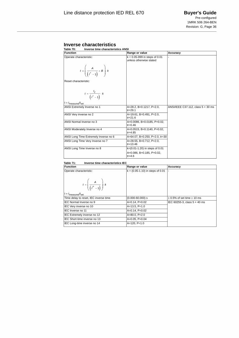
Line distance protection IED REL 670 Buyer's GuidePre-configured
1MRK 506 264-BENRevision: G, Page 36
Inverse characteristicsTable 70: Inverse time characteristics ANSI
Table 71: Inverse time characteristics IEC
Function Range or value AccuracyOperate characteristic:
Reset characteristic:
I = Imeasured/Iset
k = 0.05-999 in steps of 0.01 unless otherwise stated
-
ANSI Extremely Inverse no 1 A=28.2, B=0.1217, P=2.0, tr=29.1
ANSI/IEEE C37.112, class 5 + 30 ms
ANSI Very inverse no 2 A=19.61, B=0.491, P=2.0, tr=21.6
ANSI Normal Inverse no 3 A=0.0086, B=0.0185, P=0.02, tr=0.46
ANSI Moderately Inverse no 4 A=0.0515, B=0.1140, P=0.02, tr=4.85
ANSI Long Time Extremely Inverse no 6 A=64.07, B=0.250, P=2.0, tr=30ANSI Long Time Very Inverse no 7 A=28.55, B=0.712, P=2.0,
tr=13.46ANSI Long Time Inverse no 8 k=(0.01-1.20) in steps of 0.01
A=0.086, B=0.185, P=0.02, tr=4.6
Function Range or value AccuracyOperate characteristic:
I = Imeasured/Iset
k = (0.05-1.10) in steps of 0.01 -
Time delay to reset, IEC inverse time (0.000-60.000) s ± 0.5% of set time ± 10 msIEC Normal Inverse no 9 A=0.14, P=0.02 IEC 60255-3, class 5 + 40 msIEC Very inverse no 10 A=13.5, P=1.0IEC Inverse no 11 A=0.14, P=0.02IEC Extremely inverse no 12 A=80.0, P=2.0IEC Short-time inverse no 13 A=0.05, P=0.04IEC Long-time inverse no 14 A=120, P=1.0
( )1= + ⋅
−
⎛ ⎞⎜ ⎟⎜ ⎟⎝ ⎠
P
At B k
I
( )2 1= ⋅
−
trt kI
( )1= ⋅
−
⎛ ⎞⎜ ⎟⎜ ⎟⎝ ⎠
P
At k
I

Line distance protection IED REL 670 Buyer's GuidePre-configured
1MRK 506 264-BENRevision: G, Page 37
Table 72: Inverse time characteristics for Two step undervoltage protection (PUVM, 27)
Customer defined characteristic no 17Operate characteristic:
Reset characteristic:
I = Imeasured/Iset
k=0.5-999 in steps of 0.1A=(0.005-200.000) in steps of 0.001B=(0.00-20.00) in steps of 0.01C=(0.1-10.0) in steps of 0.1P=(0.005-3.000) in steps of 0.001TR=(0.005-100.000) in steps of 0.001CR=(0.1-10.0) in steps of 0.1PR=(0.005-3.000) in steps of 0.001
IEC 60255, class 5 + 40 ms
RI inverse characteristic no 18
I = Imeasured/Iset
k=(0.05-999) in steps of 0.01 IEC 60255-3, class 5 + 40 ms
Logarithmic inverse characteristic no 19
I = Imeasured/Iset
k=(0.05-1.10) in steps of 0.01 IEC 60255-3, class 5 + 40 ms
Function Range or value AccuracyType A curve:
U< = Uset
U = Umeasured
k = (0.05-1.10) in steps of 0.01 Class 5 +40 ms
Type B curve:
U< = UsetU = Umeasured
k = (0.05-1.10) in steps of 0.01
Programmable curve:
U< = UsetU = Umeasured
k = (0.05-1.10) in steps of 0.01A = (0.005-200.000) in steps of 0.001B = (0.50-100.00) in steps of 0.01C = (0.0-1.0) in steps of 0.1D = (0.000-60.000) in steps of 0.001P = (0.000-3.000) in steps of 0.001
Function Range or value Accuracy
( )= + ⋅
−
⎛ ⎞⎜ ⎟⎜ ⎟⎝ ⎠
P
At B k
I C
( )= ⋅
−PR
TRt k
I CR
1
0.2360.339
= ⋅
−
t k
I
5.8 1.35= − ⋅⎛ ⎞⎜ ⎟⎝ ⎠
tI
Ink
=< −
<
⎛ ⎞⎜ ⎟⎝ ⎠
kt
U U
U
2.0
4800.055
32 0.5
⋅= +
< −⋅ −
<
⎛ ⎞⎜ ⎟⎝ ⎠
kt
U U
U
⋅= +
< −⋅ −
<
⎡ ⎤⎢ ⎥⎢ ⎥⎢ ⎥⎛ ⎞⎢ ⎥⎜ ⎟⎣ ⎝ ⎠ ⎦
P
k At D
U UB C
U

Line distance protection IED REL 670 Buyer's GuidePre-configured
1MRK 506 264-BENRevision: G, Page 38
Table 73: Inverse time characteristics for Two step overvoltage protection (POVM, 59)Function Range or value AccuracyType A curve:
U> = Uset
U = Umeasured
k = (0.05-1.10) in steps of 0.01 Class 5 +40 ms
Type B curve: k = (0.05-1.10) in steps of 0.01
Type C curve: k = (0.05-1.10) in steps of 0.01
Programmable curve: k = (0.05-1.10) in steps of 0.01A = (0.005-200.000) in steps of 0.001B = (0.50-100.00) in steps of 0.01C = (0.0-1.0) in steps of 0.1D = (0.000-60.000) in steps of 0.001P = (0.000-3.000) in steps of 0.001
=− >
>
⎛ ⎞⎜ ⎟⎝ ⎠
tk
U U
U
2.0
480
32 0.5 0.035
=⋅
− >⋅ − −
>
⎛ ⎞⎜ ⎟⎝ ⎠
tk
U U
U
3.0
480
32 0.5 0.035
=⋅
− >⋅ − −
>
⎛ ⎞⎜ ⎟⎝ ⎠
tk
U U
U
⋅= +
− >⋅ −
>
⎛ ⎞⎜ ⎟⎝ ⎠
P
k At D
U UB C
U
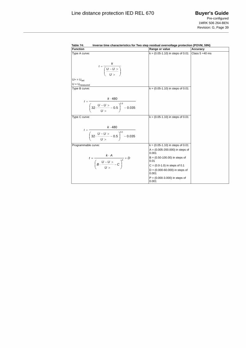
Line distance protection IED REL 670 Buyer's GuidePre-configured
1MRK 506 264-BENRevision: G, Page 39
Table 74: Inverse time characteristics for Two step residual overvoltage protection (POVM, 59N)Function Range or value AccuracyType A curve:
U> = UsetU = Umeasured
k = (0.05-1.10) in steps of 0.01 Class 5 +40 ms
Type B curve: k = (0.05-1.10) in steps of 0.01
Type C curve: k = (0.05-1.10) in steps of 0.01
Programmable curve: k = (0.05-1.10) in steps of 0.01A = (0.005-200.000) in steps of 0.001B = (0.50-100.00) in steps of 0.01C = (0.0-1.0) in steps of 0.1D = (0.000-60.000) in steps of 0.001P = (0.000-3.000) in steps of 0.001
=− >
>
⎛ ⎞⎜ ⎟⎝ ⎠
tk
U U
U
2.0
480
32 0.5 0.035
=⋅
− >⋅ − −
>
⎛ ⎞⎜ ⎟⎝ ⎠
tk
U U
U
3.0
480
32 0.5 0.035
=⋅
− >⋅ − −
>
⎛ ⎞⎜ ⎟⎝ ⎠
tk
U U
U
⋅= +
− >⋅ −
>
⎛ ⎞⎜ ⎟⎝ ⎠
P
k At D
U UB C
U
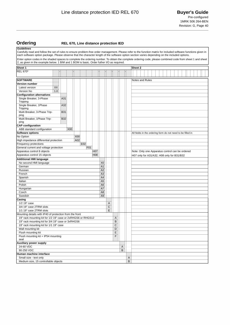
Line distance protection IED REL 670 Buyer's GuidePre-configured
1MRK 506 264-BENRevision: G, Page 40
Ordering REL 670, Line distance protection IEDGuidelinesCarefully read and follow the set of rules to ensure problem-free order management. Please refer to the function matrix for included software functions given in each software option package. Please observe that the character length of the software option section varies depending on the included options.Enter option codes in the shaded spaces to complete the ordering number. To obtain the complete ordering code, please combined code from sheet 1 and sheet 2, as given in the example below. 1 BIM and 1 BOM is basic. Order futher I/O as required.
Sheet 1 Sheet 2REL 670* - - - - - - -
SOFTWARE Notes and RulesVersion number
Latest version XXVersion No 1.0
Configuration alternativesSingle Breaker, 3-Phase Tripping
A31
Single Breaker, 1Phase Tripping
A32
Multi Breaker, 3-Phase Trip-ping
B31
Multi Breaker, 1Phase Trip-ping
B32
CAP configurationABB standard configuration X00
Software options All fields in the ordering form do not need to be filled inNo Option X00High impedance differential protection A02Frequency protections E02General current and voltage protection F01Apparatus control 8 objects H07 Note: Only one Apparatus control can be ordered
H07 only for A31/A32, H08 only for B31/B32Apparatus control 15 objects H08Additional HMI language
No second HMI language X0German A1Russian A2French A3Spanish A4Italian A5Polish A6Hungarian A7Czech A8Swedish A9
Casing1/2 19” case A3/4 19” case 2TRM slots C1/1 19” case 2TRM slots E
Mounting details with IP40 of protection from the front19” rack mounting kit for 1/2 19” case or 2xRHGS6 or RHGS12 A19” rack mounting kit for 3/4 19” case or 3xRHGS6 B19” rack mounting kit for 1/1 19” case CWall mounting kit DFlush mounting kit EFlush mounting kit + IP54 mounting seal
F
Auxiliary power supply24-60 VDC A90-250 VDC B
Human machine interfaceSmall size - text only AMedium size, 15 controllable objects B
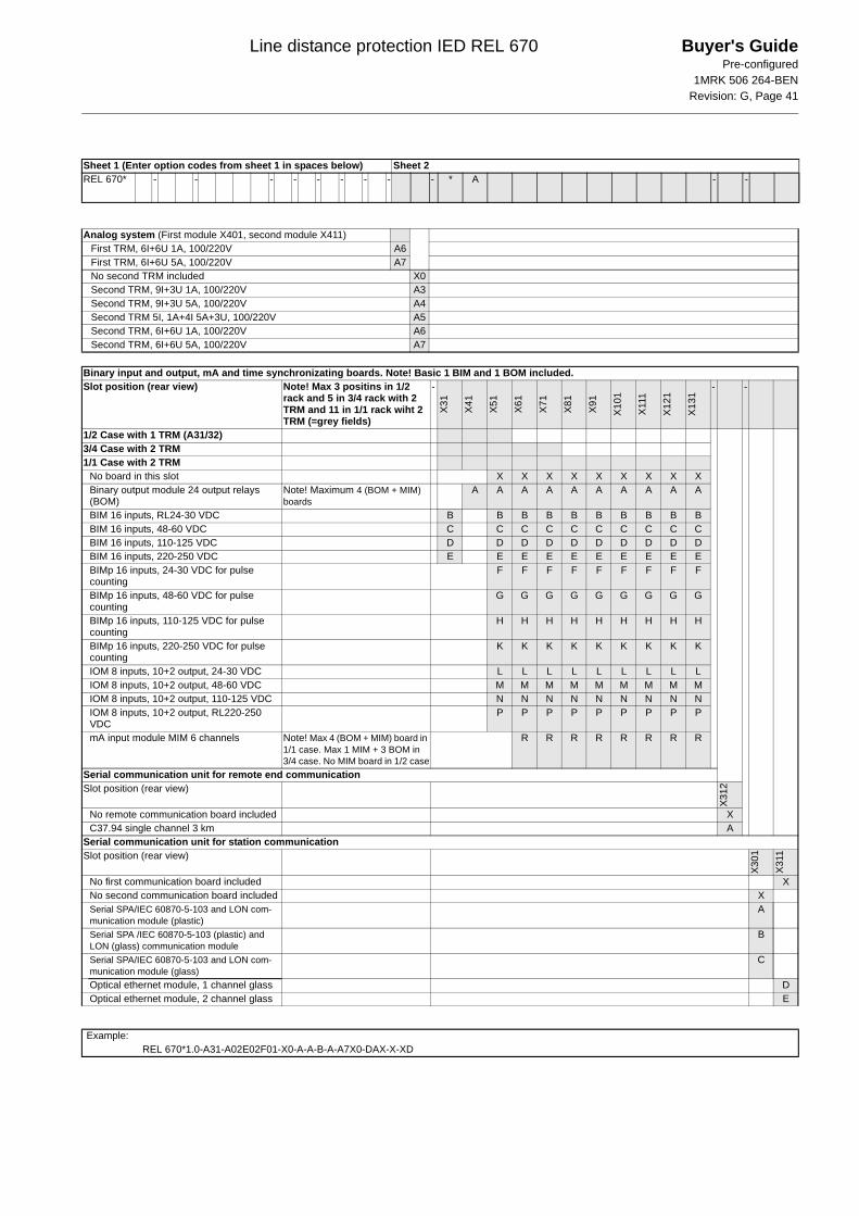
Line distance protection IED REL 670 Buyer's GuidePre-configured
1MRK 506 264-BENRevision: G, Page 41
Sheet 1 (Enter option codes from sheet 1 in spaces below) Sheet 2REL 670* - - - - - - - - - * A - -
Analog system (First module X401, second module X411)First TRM, 6I+6U 1A, 100/220V A6First TRM, 6I+6U 5A, 100/220V A7No second TRM included X0Second TRM, 9I+3U 1A, 100/220V A3Second TRM, 9I+3U 5A, 100/220V A4Second TRM 5I, 1A+4I 5A+3U, 100/220V A5Second TRM, 6I+6U 1A, 100/220V A6Second TRM, 6I+6U 5A, 100/220V A7
Binary input and output, mA and time synchronizating boards. Note! Basic 1 BIM and 1 BOM included.Slot position (rear view) Note! Max 3 positins in 1/2
rack and 5 in 3/4 rack with 2 TRM and 11 in 1/1 rack wiht 2 TRM (=grey fields)
-
X31
X41
X51
X61
X71
X81
X91
X10
1
X111
X12
1
X13
1
- -
1/2 Case with 1 TRM (A31/32)3/4 Case with 2 TRM1/1 Case with 2 TRM
No board in this slot X X X X X X X X XBinary output module 24 output relays (BOM)
Note! Maximum 4 (BOM + MIM) boards
A A A A A A A A A A
BIM 16 inputs, RL24-30 VDC B B B B B B B B B BBIM 16 inputs, 48-60 VDC C C C C C C C C C CBIM 16 inputs, 110-125 VDC D D D D D D D D D DBIM 16 inputs, 220-250 VDC E E E E E E E E E EBIMp 16 inputs, 24-30 VDC for pulse counting
F F F F F F F F F
BIMp 16 inputs, 48-60 VDC for pulse counting
G G G G G G G G G
BIMp 16 inputs, 110-125 VDC for pulse counting
H H H H H H H H H
BIMp 16 inputs, 220-250 VDC for pulse counting
K K K K K K K K K
IOM 8 inputs, 10+2 output, 24-30 VDC L L L L L L L L LIOM 8 inputs, 10+2 output, 48-60 VDC M M M M M M M M MIOM 8 inputs, 10+2 output, 110-125 VDC N N N N N N N N NIOM 8 inputs, 10+2 output, RL220-250 VDC
P P P P P P P P P
mA input module MIM 6 channels Note! Max 4 (BOM + MIM) board in 1/1 case. Max 1 MIM + 3 BOM in 3/4 case. No MIM board in 1/2 case
R R R R R R R R
Serial communication unit for remote end communicationSlot position (rear view)
X31
2
No remote communication board included XC37.94 single channel 3 km A
Serial communication unit for station communicationSlot position (rear view)
X301
X31
1
No first communication board included XNo second communication board included XSerial SPA/IEC 60870-5-103 and LON com-munication module (plastic)
A
Serial SPA /IEC 60870-5-103 (plastic) and LON (glass) communication module
B
Serial SPA/IEC 60870-5-103 and LON com-munication module (glass)
C
Optical ethernet module, 1 channel glass DOptical ethernet module, 2 channel glass E
Example:REL 670*1.0-A31-A02E02F01-X0-A-A-B-A-A7X0-DAX-X-XD
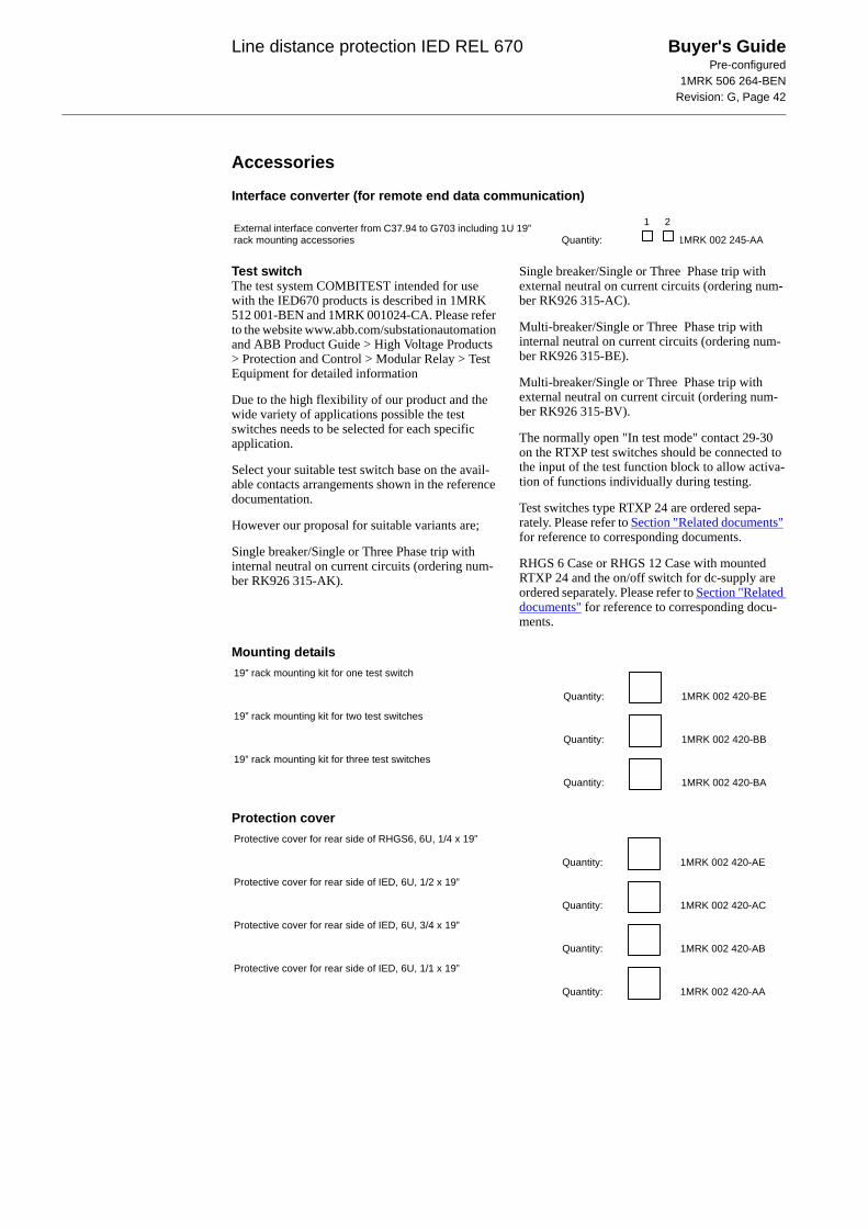
Line distance protection IED REL 670 Buyer's GuidePre-configured
1MRK 506 264-BENRevision: G, Page 42
Accessories
Interface converter (for remote end data communication)
Test switchThe test system COMBITEST intended for use with the IED670 products is described in 1MRK 512 001-BEN and 1MRK 001024-CA. Please refer to the website www.abb.com/substationautomation and ABB Product Guide > High Voltage Products > Protection and Control > Modular Relay > Test Equipment for detailed information
Due to the high flexibility of our product and the wide variety of applications possible the test switches needs to be selected for each specific application.
Select your suitable test switch base on the avail-able contacts arrangements shown in the reference documentation.
However our proposal for suitable variants are;
Single breaker/Single or Three Phase trip with internal neutral on current circuits (ordering num-ber RK926 315-AK).
Single breaker/Single or Three Phase trip with external neutral on current circuits (ordering num-ber RK926 315-AC).
Multi-breaker/Single or Three Phase trip with internal neutral on current circuits (ordering num-ber RK926 315-BE).
Multi-breaker/Single or Three Phase trip with external neutral on current circuit (ordering num-ber RK926 315-BV).
The normally open "In test mode" contact 29-30 on the RTXP test switches should be connected to the input of the test function block to allow activa-tion of functions individually during testing.
Test switches type RTXP 24 are ordered sepa-rately. Please refer to Section "Related documents" for reference to corresponding documents.
RHGS 6 Case or RHGS 12 Case with mounted RTXP 24 and the on/off switch for dc-supply are ordered separately. Please refer to Section "Related documents" for reference to corresponding docu-ments.
Mounting details
Protection cover
External interface converter from C37.94 to G703 including 1U 19” rack mounting accessories Quantity: 1MRK 002 245-AA
1 2
19” rack mounting kit for one test switch
Quantity: 1MRK 002 420-BE
19” rack mounting kit for two test switches
Quantity: 1MRK 002 420-BB
19” rack mounting kit for three test switches
Quantity: 1MRK 002 420-BA
Protective cover for rear side of RHGS6, 6U, 1/4 x 19”
Quantity: 1MRK 002 420-AE
Protective cover for rear side of IED, 6U, 1/2 x 19”
Quantity: 1MRK 002 420-AC
Protective cover for rear side of IED, 6U, 3/4 x 19”
Quantity: 1MRK 002 420-AB
Protective cover for rear side of IED, 6U, 1/1 x 19”
Quantity: 1MRK 002 420-AA
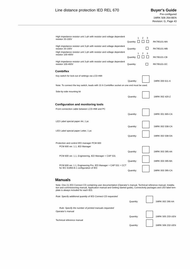
Line distance protection IED REL 670 Buyer's GuidePre-configured
1MRK 506 264-BENRevision: G, Page 43
Combiflex
Configuration and monitoring tools
Manuals
High impedance resistor unit 1-ph with resistor and voltage dependent resistor 20-100V
Quantity: RK795101-MA
High impedance resistor unit 3-ph with resistor and voltage dependent resistor 20-100V Quantity: RK795101-MBHigh impedance resistor unit 1-ph with resistor and voltage dependent resistor 100-400V
Quantity: RK795101-CB
High impedance resistor unit 3-ph with resistor and voltage dependent resistor 100-400V Quantity: RK795101-DC
1 2 3
1 2 3
Key switch for lock-out of settings via LCD-HMI
Quantity: 1MRK 000 611-A
Note: To connect the key switch, leads with 10 A Combiflex socket on one end must be used.
Side-by-side mounting kit
Quantity: 1MRK 002 420-Z
Front connection cable between LCD-HMI and PC
Quantity: 1MRK 001 665-CA
LED Label special paper A4, 1 pc
Quantity: 1MRK 002 038-CA
LED Label special paper Letter, 1 pc
Quantity: 1MRK 002 038-DA
Protection and control IED manager PCM 600PCM 600 ver. 1.1, IED Manager
Quantity: 1MRK 003 395-AA
PCM 600 ver. 1.1, Engineering, IED Manager + CAP 531
Quantity: 1MRK 003 395-BA
PCM 600 ver. 1.1, Engineering Pro, IED Manager + CAP 531 + CCT for IEC 61850-8-1 configuration of IED
Quantity: 1MRK 003 395-CA
Note: One (1) IED Connect CD containing user documentation (Operator’s manual, Technical reference manual, Installa-tion and commissioning manual, Application manual and Getting started guide), Connectivity packages and LED label tem-plate is always included for each IED.
Rule: Specify additional quantity of IED Connect CD requested
Quantity: 1MRK 002 290-AA
Rule: Specify the number of printed manuals requestedOperator’s manual
Quantity: 1MRK 505 233-UENTechnical reference manual
Quantity: 1MRK 506 232-UEN
Line distance protection IED REL 670 Buyer's GuidePre-configured
1MRK 506 264-BENRevision: G, Page 44
Reference information
Related documents
Manufacturer
Installation and commissioning manual
Quantity: 1MRK 506 234-UENApplication manual
Quantity: 1MRK 505 235-UENEngineering guide IED 670 products
Quantity: 1MRK 511 179-UEN
For our reference and statistics we would be pleased to be provided with the following application data:
Country: End user:
Station name: Voltage level: kV
Documents related to REL 670 Identity numberOperator’s manual 1MRK 505 233-UENInstallation and commissioning manual 1MRK 506 234-UENTechnical reference manual 1MRK 506 232-UENApplication manual 1MRK 505 235-UENBuyer’s guide 1MRK 506 264-BENConnection diagram, Single breaker arr. Three phase tripping arr. 1MRK 002 801-BAConnection diagram, Single breaker arr. Single phase tripping arr. 1MRK 002 801-CAConnection diagram, Multi breaker arr. Three phase tripping arr. 1MRK 002 801-DAConnection diagram, Multi breaker arr. Single phase tripping arr. 1MRK 002 801-EAConfiguration diagram A, Single breaker with single or double busbar 1MRK 004 500-86Configuration diagram B, Single breaker with single or double busbar 1MRK 004 500-87Configuration diagram C, Multi breaker such as 1 1/2 or ring busbar arr. 1MRK 004 500-88Configuration diagram D, Multi breaker such as 1 1/2 or ring busbar arr. 1MRK 004 500-89Setting example 1, 400 kV Long overhead power line with 1 1/2 CB arr. 1MRK 506 267-WENSetting example 2, 230 kV Extremely long overhead power line, double bus, single CB arr. 1MRK 506 268-WENSetting example 3, 132 kV Short overhead power line, double bus, single CB arr. 1MRK 506 269-WEN
Connection and Installation components 1MRK 013 003-BENTest system, COMBITEST 1MRK 512 001-BENAccessories for IED 670 1MRK 514 012-BENGetting started guide IED 670 1MRK 500 065-UENSPA and LON signal list for IED 670 1MRK 500 075-WENIEC 61850 Data objects list for IED 670 1MRK 500 077-WENGeneric IEC 61850 IED Connectivity package 1KHA001027–UENProtection and Control IED Manager PCM 600 Installation sheet 1MRS755552Engineering guide IED 670 products 1MRK 511 179–UEN
Latest versions of the described documentation can be found on www.abb.com/substationautomation
ABB Power Technologies ABSubstation Automation ProductsSE-721 59 VästeråsSwedenTelephone: +46 (0) 21 34 20 00Facsimile: +46 (0) 21 14 69 18Internet: www.abb.com/substationautomation