lincoln electric external evaluation...welding electrodes final report for lincoln electric company...
TRANSCRIPT

Lincoln Electric External EvaluationEvaluation of EXX45-P2 Welding Electrodes
Evaluation of EXX45-P2 Welding Electrodes
Final Report for Lincoln Electric Company Report No.: 82674761 April 22, 2008

Final Report 82674761 Page i
Evaluation of EXX45-P2 Welding Electrodes for
Lincoln Electric Company Consumable Research & Development 22801 St. Clair Avenue Cleveland, OH 44117 Attention: Mr. Ashish Kapoor
CC TECHNOLOGIES, INC.
5777 Frantz Road Dublin, Ohio 43017-1386
USA
Tel: 614-761-1214 Fax: 614-761-1633
http://www.dnv.com http://www.cctechnologies.com
Summary: CC Technologies, Inc. (CCT) was requested by Lincoln Electric
Company (Lincoln) to perform an evaluation of a newly-developed series of low-hydrogen welding electrodes. These electrodes are intended to operate in the vertical-down direction (i.e., AWS EXX45-P2-type). In particular, the evaluation focused on the application of these electrodes for welding onto in-service pipelines for the installation of full-encirclement repair sleeves and hot tap branch connections.
Prepared By: William A. Bruce Director Welding Technology
Bradley C. Etheridge Welding Engineer
Approved By: Patrick H. Vieth Senior VP Integrity & Materials
Date of Issue: April 22, 2008
Project No: 82674761 No distribution without permission from the client or responsible organizational unit (however, free distribution for internal use within DNV after 3 years). All copyrights reserved. This publication or parts thereof may not be reproduced or transmitted in any form or by any means, including photocopying or recording, without the prior written consent of CC Technologies, Inc. (A DNV Company).

Final Report 82674761 Page ii
Table of Contents Page
1. INTRODUCTION .................................................................................................................. 1
2. OBJECTIVE ........................................................................................................................... 1
3. PROGRAM OF WORK ......................................................................................................... 1
3.1 Material Procurement and Consumable Evaluation ....................................................... 2 3.2 Procedure Development Trials ....................................................................................... 2 3.3 Full-Scale Procedure Qualification................................................................................. 4
4. RESULTS ............................................................................................................................... 4
4.1 Procedure Development Trials. ...................................................................................... 4 4.2 Full-Scale Procedure Qualification................................................................................. 5
5. DISCUSSION......................................................................................................................... 5
6. SUMMARY AND CONCLUSIONS ..................................................................................... 6
7. REFERENCES ....................................................................................................................... 8

Final Report 82674761 Page iii
List of Tables Page Table 1. Diffusible Hydrogen Analysis Results for Lincoln LH-D Electrodes
(provided by Lincoln) ............................................................................................. 9 Table 2. Chemical Analysis Results ..................................................................................... 9 Table 3. Matrix of Sleeve Fillet Weld Trials for Lincoln LH-D Electrodes....................... 10 Table 4. Welding Parameters for Weld No. D01 (3.2 mm diameter E8045-P2) ................ 10 Table 5. Welding Parameters for Weld No. D02 (4.0 mm diameter E8045-P2) ................ 10 Table 6. Welding Parameters for Weld No. D03 (4.5 mm diameter E8045-P2) ................ 11 Table 7. Welding Parameters for Weld No. D04 (3.2 mm diameter E9045-P2) ................ 11 Table 8. Welding Parameters for Weld No. D05 (3.2 mm diameter E10045-P2) .............. 11 Table 9. Matrix of Sleeve Fillet Weld Trials for Other Electrodes..................................... 12 Table 10. Diffusible Hydrogen Analysis Results for Other Electrodes................................ 12 Table 11. Welding Parameters for Weld No. D013 (3.2 mm diameter E6010).................... 12 Table 12. Welding Parameters for Weld No. D012 (3.2 mm
diameter E7018 - <4 ml/100 gm).......................................................................... 13 Table 13. Welding Parameters for Weld No. D014 (3.2 mm
diameter E7018 - ~14 ml/100 gm)........................................................................ 13 Table 14. Welding Parameters for Weld No. D09B (Branch Weld – Second Attempt) ...... 14 Table 15. Welding Parameters for Weld No. D10B (Branch Weld – Third Attempt) ......... 15 Table 16. Welding Parameters for Procedure Qualification Weld – West End.................... 16 Table 17. Welding Parameters for Procedure Qualification Weld – East End ..................... 17 Table 18. Procedure Development Trial Results – Lincoln LH-D Electrodes ..................... 18 Table 19. Procedure Development Trial Results – Other Electrodes ................................... 19 Table 20. Procedure Qualification Trial Results................................................................... 19

Final Report 82674761 Page iv
List of Figures Page Figure 1. Setup for procedure development trials using water backing............................... 20
Figure 2. Setup for procedure development trials – sleeve fillet welds. .............................. 20
Figure 3. Anchor welds and controlled 1/16 in. root gap for sleeve fillet welds. ................ 21
Figure 4. Fillet Weld Sequence ............................................................................................ 21
Figure 5. Deposition of procedure development trials – sleeve fillet welds. ....................... 22
Figure 6. Typical completed procedure development trial – sleeve fillet weld. .................. 22
Figure 7. Setup for procedure development trials – Branch groove welds. ......................... 23
Figure 8. Restraining strongbacks for branch groove welds. ............................................... 23
Figure 9. Typical completed procedure development trial – branch groove weld............... 24
Figure 10. Extracted specimens from sleeve fillet weld. ....................................................... 24
Figure 11. Extracted specimens (minus metallographic sections) from branch groove weld.25
Figure 12. Setup for full-scale procedure qualification weld................................................. 25
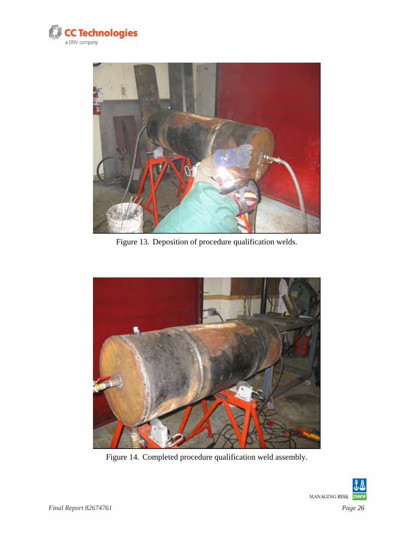
Figure 13. Deposition of procedure qualification welds. ....................................................... 26
Figure 14. Completed procedure qualification weld assembly. ............................................. 26
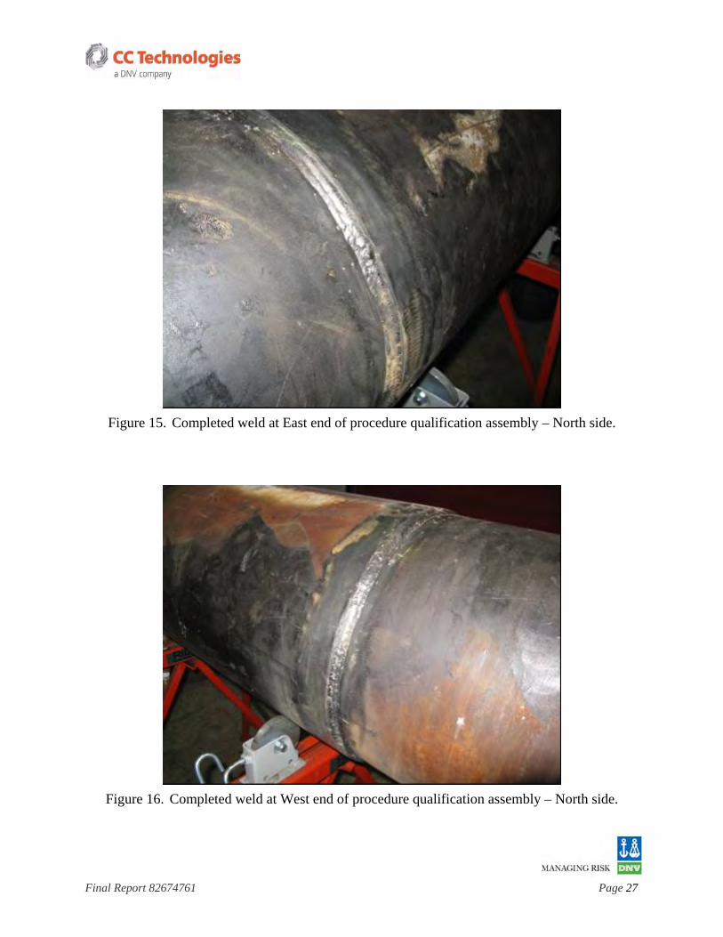
Figure 15. Completed weld at East end of procedure qualification assembly – North side. . 27
Figure 16. Completed weld at West end of procedure qualification assembly – North side. 27
Figure 17. Close up of completed weld at West end of procedure qualification assembly - South side............................................................................................ 28
Figure 18. Macrograph of typical procedure development trial weld (Weld No. D01) made using Lincoln LH-D electrodes............................................................................. 28
Figure 19. Macrograph of procedure development trial Weld No. D13 made using E6010 electrodes. ............................................................................................................. 29
Figure 20. Appearance of face bend specimen from Weld No. D13 made using E6010 electrodes showing weld to crack. ........................................................................ 29
Figure 21. Appearance of face bend specimen from Weld No. D14 made using E7018 electrodes with ~14 ml/100 gm showing weld metal cracks. ............................... 30
Figure 22. Macrograph of full-scale procedure qualification weld made using Lincoln LH-D electrodes. ............................................................................................................. 30

Final Report 82674761 Page 1
1. INTRODUCTION
CC Technologies, Inc. (CCT) was requested by Lincoln Electric Company (Lincoln) to perform an evaluation of a newly-developed series of low-hydrogen welding electrodes. These electrodes are intended to operate in the vertical-down direction (i.e., AWS EXX45-P2-type). In particular, the evaluation focused on the application of these electrodes for welding onto in-service pipelines for the installation of full-encirclement repair sleeves and hot tap branch connections.
Welding onto a pipeline after it has been put into service is frequently required for several reasons. Repair sleeves are installed to reinforce areas of corrosion or mechanical damage, and branch connections are made for system modifications. There are often significant economic and environmental incentives to perform this welding without removing the system from service. These include the ability to maintain operations during welding and the ability to avoid venting the contents to the atmosphere. Welds made onto in-service pipelines cool at an accelerated rate as the result of the flowing contents' ability to remove heat from the pipe wall. These welds, therefore, are likely to have hard heat-affected zones (HAZs) and to be susceptible to hydrogen cracking. There is also a risk of ‘burnthrough’, where the welding arc causes the pipe wall to be penetrated allowing the contents to escape.
The most commonly used process for welding onto in-service pipelines is shielded-metal arc welding (SMAW) using conventional vertical-up low-hydrogen electrodes (AWS EXX18-type). Vertical-down low hydrogen electrodes have become an attractive alternative to conventional electrodes for this application because of operator appeal and the potential for increased productivity. The utility of vertical-down low hydrogen electrodes for welding onto in-service pipelines has been previously established.(1)
2. OBJECTIVE
The objective of this project was to perform a critical evaluation of a newly-developed series of low-hydrogen vertical-down pipe welding electrodes (EXX45-P2-type) for in-service hot tapping and repair applications.
3. PROGRAM OF WORK
The work that was carried out was divided into several tasks. In the first task, materials were procured and the newly-developed electrodes were subjected to a preliminary evaluation. In the second task, procedure development trials were carried out in small scale under simulated in-service conditions to verify the suitability of these electrodes under simulated in-service conditions and to determine their ability to produce welds that are sound and free from cracks. In the third task, a typical welding procedure was qualified in full-scale, again under simulated conditions, to the requirements of relevant industry codes. The work is described in detail below.

Final Report 82674761 Page 2
3.1 Material Procurement and Consumable Evaluation
A supply of the newly-developed electrodes was procured in three different diameters (3.2, 4.0, and 5.0 mm) and in three different strength levels (E8045-P2, E9045-P2, and E10045-P2). The trade names for the three different strength levels are LH-D80, LH-D90, and LH-D100, respectively. Diffusible hydrogen testing results for these electrodes, as provided by Lincoln are shown in Table 1. Trial welds (simple lap fillet welds) were made initially to evaluate the operability of each diameter and strength level and to allow the welding technician to become familiar with the operation of these electrodes.
The experimental evaluation described below focused initially on a single electrode diameter (3.2 mm) and a single strength level (E8045-P2). A subset of duplicate tests was conducted for the other two diameters and strength levels, as described below. A base material with a carbon equivalent level typical of older vintage line pipe material was procured. To simplify test specimen fabrication, material in plate form was used for the procedure development trials. This material is a 0.375 in. (9.5 mm) thick ASTM A516-60 with a carbon equivalent (CEIIW) of 0.435. The procedure qualification trial involved a full diameter of line pipe material. This same line pipe material, which is a 16 in. diameter by 0.250 in. (6.4 mm) thick API 5LX-52 with a CEIIW of 0.416, was also used to fabricate the sleeve portion of the procedure qualification assembly. Chemical composition results for both the plate and the pipe material are shown in Table 2.
3.2 Procedure Development Trials
The purpose of these procedure development trials was to determine, in small-scale, the ability of the newly-developed electrodes to produce sound, crack free welds under simulated in-service conditions. The methodology that was used for the procedure development trials followed that which has been used in previous similar work.(2) Small-scale multi-pass welds (approximately 12 in. [304.8 mm] long) were deposited under simulated in-service conditions using a highly-restrained geometry. The accelerated cooling methods used previously(3) were employed so that realistic weld cooling rates and weld solidification characteristics would result. The 0.375 in. (9.5 mm) thick ASTM A516-60 plate material was welded into an apparatus that allows welds to be made while water flows across the back side (Figure 1).
A multi-pass sleeve fillet weld geometry was used initially. Smaller panels of the plate material were anchor-welded to a larger panel so that welds simulating the fillet weld between the end of a full-encirclement repair sleeve and the pipe could be deposited (Figure 2). A controlled gap of 1/16 in. (1.6 mm), similar to that of a controlled thermal severity (CTS) test specimen (Figure 3), was provided so that the geometry (i.e., the stress concentration) at the root of each weld would be consistent. The width of the panel anchor-welded to each larger panel was 6 in. (152.4 mm). The length of the smaller panel was 12 in. (304.8 mm), allowing a 12-in. (304.8 mm) long fillet weld to be produced so that an appropriate number of metallographic specimens and appropriately-sized test coupons could be extracted.
The simulated thermal conditions that result from this experimental set-up have been shown to result in weld cooling rates that are as fast or faster than most typical in-service
Final Report 82674761 Page 3
welding applications.(3) During these trials, the water flow rate was approximately 10 gal/min and the water temperature was approximately 45° F. The ambient (room) temperature was approximately 65° F. All welds were made with the panels in the 45-degree position.
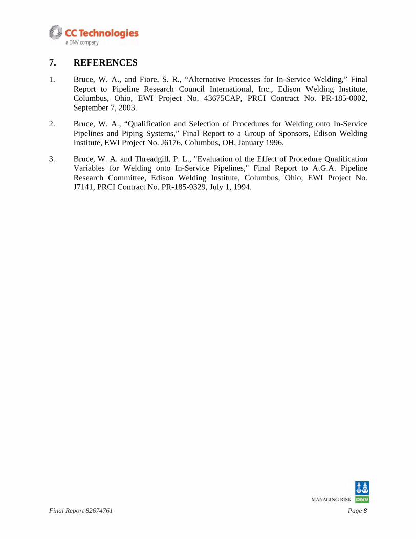
Simulated sleeve fillet welds were made initially using the 3.2 mm diameter E8045-P2 electrodes. A subset of duplicate tests was conducted for the other two diameters and strength levels. The matrix of sleeve fillet weld trials that were conducted is shown in Table 3. Each electrode diameter and strength level was used to deposit a three-pass fillet weld using the sequence shown in Figure 4. Welds were made using a current setting that was recommended by Lincoln. For welds made using the 3.2 mm diameter electrodes, a travel speed that would result in a heat input of approximately 25 kJ/in. (1.0 kJ/mm) was used. For other electrode diameters, travel speed was left to the discretion of the welding technician. During welding (Figure 5), welding parameters were recorded for each pass. These are shown in Tables 4 through 8. The external appearance of a typical completed weld is shown in Figure 6.
Three additional sleeve fillet welds, as shown in Table 9, were made for comparison purposes. One (Weld No. D13) was made using 3.2 mm E6010 electrodes and the other two were made using standard (vertical-up) E7018 electrodes. The electrodes that were used for Weld No. D12 had a diffusible hydrogen level of <4 ml/100 gm of deposited weld metal. The electrodes that were used for Weld No. D14 had a diffusible hydrogen level of approximately 14 ml/100 gm. Diffusible hydrogen testing results for these two electrodes are shown in Table 10. Welding parameters for these additional welds are shown in Tables 11 through 13.
Several highly-restrained multi-pass branch groove welds were made next to evaluate the potential of these electrodes for the installation of stub-on branches. The setup for these involved welding another panel of the 0.375-in. (9.5-mm)-thick ASTM A516 material into the apparatus that allows welds to be made while water flows across the back side. Smaller panels of the same material were then attached perpendicular to this panel using strong-backs so that welds simulating the groove weld between a stub-on branch and the pipe could be deposited (Figures 7 and 8). The length of the smaller panel was 12 in. (304.8 mm), allowing a 12-in. (304.8-mm) -long branch groove weld to be produced. The smaller panel was prepared with a 45 degree bevel. Various combinations of land thickness and root opening were used in an attempt to produce an acceptable root pass. Three welds were attempted, one of which was abandoned prior to completion. Welding parameters for the other two are shown in Tables 14 and 15. The external appearance of a typical completed weld is shown in Figure 9. The welding technician reported that, in general, these electrodes are not well suited for the root pass of an open-root branch groove weld.
After a 24-hour delay time, the welds were sectioned so that metallographic examination, hardness testing, and mechanical testing (nick-break and toe bend test) could be performed (Figures 10 and 11). On the saw-cut edges of both branch groove welds that were completed, excessive lack of root penetration and porosity could be seen, so further effort pertaining to branch groove welds was abandoned. For the remainder of the welds, four metallographic sections and six mechanical test specimens (for both nick-break and face bend testing) were removed from each.

Final Report 82674761 Page 4
3.3 Full-Scale Procedure Qualification
A welding procedure qualification trial was carried out using a full diameter of pipe. The purpose of this procedure qualification trial was to demonstrate that the newly-developed electrodes could be used to execute welds in all positions. The trial involved fillet welds around the ends of a full-encirclement repair sleeve.
The sleeve was fabricated by splitting and expanding two sections of the 16-in. diameter pipe so that the inside of the sleeve would fit the outside of the pipe. Thermal conditions that simulate the ability of the pipeline contents to remove heat from the pipe wall were again established so that realistic cooling rates would result. End plates, water connections, etc., were welded in place similar to the arrangement shown in Appendix B of API 1104 so that water could flow through the pipe while the procedure qualification welds were made. The assembly that was used is shown in Figure 12. The longitudinal seam welds for a full encirclement sleeve, which are not normally considered in-service welds since they are made using a backing strip, were not included in this trial.
The procedure qualifications involved the use of 3.2 mm diameter E8045-P2 electrodes for all passes. A three-pass fillet sequence (Figure 4) was used. A travel speed that would result in a heat input of approximately 25 kJ/in. (1.0 kJ/mm) was used. The circumferential fillet weld on one end of the full-encirclement sleeve was completed before beginning the circumferential fillet weld on the other end. During welding (Figure 13), welding parameters were recorded for each pass. These are shown in Tables 16 and 17. The external appearance of the completed welds is shown in Figure 14 through 17.
After a 24-hour delay time, the welds were sectioned so that procedure qualification testing to the requirements of a variety of codes could be conducted. These codes included Appendix B of API 1104, API 1107, ASME IX, BS 6990 (BS 4515) and CSA Z662. Many of the requirements listed in these codes are common. Four metallographic sections and six mechanical test specimens (for both nick-break and face bend testing) were removed from each weld. HAZ hardness testing was performed on two of the metallographic sections from each weld.
4. RESULTS
4.1 Procedure Development Trials.
The results of the procedure development trials are shown in Tables 18 and 19. The results of both mechanical testing and metallographic examination indicate that all of the welds made using Lincoln LH-D electrodes are sound and free from cracks. A macrograph of a typical weld made using Lincoln LH-D electrodes (Weld No. D01) is shown in Figure 18. This was also the case for the weld made using standard E7018 (vertical-up) electrodes with a diffusible hydrogen level of < 4 ml/100 gm.

Final Report 82674761 Page 5
In contrast, the weld made using E6010 electrodes and standard E7018 (vertical-up) electrodes with a diffusible hydrogen level of approximately 14 ml/100 gm both contain cracks. The weld made using E6010 electrodes (Weld No. D13) developed a through thickness crack that initiated at the weld root and propagated though the simulated sleeve material, resulting in a complete separation of the sleeve material along the majority of the weld length. This weld also contains weld metal cracking and HAZ cracking at the weld toe. A macrograph of the weld made using E6010 electrodes is shown in Figure 19 and the a face bend test specimen from this weld showing a weld toe crack is shown in Figure 20. The weld made using standard E7018 (vertical-up) electrodes with a diffusible hydrogen level of approximately 14 ml/100 gm (Weld No. D14) contains extensive weld metal cracking. A face bend specimen from this weld showing weld metal cracking is shown in Figure 21.
HAZ hardness values for welds made using 3.2 mm diameter electrodes at a heat input of approximately 25 kJ/in. (1.0 kJ/mm) are in the 400 to 450 HV range. Welds made using larger diameter Lincoln LH-D electrodes at a higher heat input have similar HAZ hardness values. The absence of cracks in the welds made using Lincoln LH-D electrodes and the weld made using standard E7018 (vertical-up) electrodes with a diffusible hydrogen level of < 4 ml/100 gm, despite the relatively high HAZ hardness values, is the result of close control of weld hydrogen level.
4.2 Full-Scale Procedure Qualification
The results of the full-scale procedure qualification welds made using Lincoln LH-D electrodes are shown in Table 20. The results of both mechanical testing and metallographic examination indicate that the welds are sound and free from cracks. HAZ hardness values are in the 380 HV range. A macrograph of the full-scale procedure qualification weld made using Lincoln LH-D electrodes is shown in Figure 22.
A welding procedure specification can be written from the parameters that were used for the full-scale procedure qualification. The welding parameter data contained in Table 16 and 17 and the procedure qualification test results contained in Table 20 can be used to produce a procedure qualification record. The testing that was performed is sufficient to develop WPS and PQR combinations to the requirements of a variety of codes, including Appendix B of API 1104.
5. DISCUSSION
Welds made onto in-service pipelines are particularly susceptible to hydrogen cracking not only because hard HAZ microstructures tend to develop as the result of fast weld cooling rates (i.e., short 800 to 500°C weld cooling times), but also because fast weld cooling rates (i.e., cooling times to 100°C ) tend to cause any hydrogen that enters the weld to become trapped there. These welds are therefore particularly sensitive to weld hydrogen level.
The results of diffusible hydrogen testing provided by Lincoln indicate that the Lincoln LH-D electrodes have less than 4 ml/100 gm of deposited weld metal, making them well suited for in-service welding. In addition, these electrodes are supplied with the AWS ‘H4R’ supplemental designator. Electrodes with this supplemental designator are guaranteed to

Final Report 82674761 Page 6
produce welds with a hydrogen level of 4 ml/100 gm or less in the “as-received” condition and are supplied with a moisture resistant coating. The Lincoln LH-D electrodes are also packaged in small-quantity, hermetically-sealed containers, making them ideally suited for field use.
The procedure development welds using 3.2 mm diameter electrodes were made at a nominal heat input of approximately 25 kJ/in. (1.0 kJ/mm). Welds made at this heat input on 0.42 CEIIW material under the simulated conditions used for the procedure development trials have been shown to be just below the hydrogen cracking threshold as long as the diffusible hydrogen level is controlled to less that 4 ml/100 gm of deposited weld metal (i.e., welds with diffusible hydrogen just above this level tend to contain cracks).
In terms of operability, the use of the Lincoln LH-D electrodes did require a short period of learning on the part of the welding technician, who had no prior experience with this type of electrode. The main operability problems that needed to be overcome were avoiding starting porosity at the beginning of each weld run and running at a current level higher than what the welding technician was accustom to for a given electrode diameter. Two batches of the 3.2 mm diameter E8045-P2 electrodes were provided by Lincoln. The first batch, which were similar to the remainder of the electrode diameters and strength levels, contained an exothermic compound, in addition to a sharpened (i.e., ‘pencil point’) core wire, on the tip of the electrode. The second batch contained only a sharpened core wire (i.e., no exothermic compound). The welding technician preferred the second batch. The presence of the exothermic compound would sometimes prevent the electrodes from starting reliably on the first attempt. When the electrodes would start, the somewhat violent action of the exothermic compound would sometimes startle the welding technician, causing him to momentarily pull away from the base material. This brief period of excessive arc length would then tend to result in starting porosity. Electrodes with the sharpened core wire and the exothermic compound were used for the procedure development trials and electrodes with the sharpened core wire only were used for the full-scale procedure qualification. Other than this difficulty, which was eventually overcome, the welding technician reported that, in general, the steady-state operability of all the electrodes was good.
During previous work that involved similar full-scale procedure qualification trials using a variety of welding processes and electrode types,(1) welding parameters and productivity (arc time, amount of between-pass cleaning required, etc.) were monitored and compared. The results of this indicate that the total time to complete one end of a full-encirclement repair sleeve on 16 in. diameter pipe using standard E7018 (vertical-up) electrodes was 37 minutes. The amount of time required using low-hydrogen vertical down electrodes was 29 minutes, which represents a 22% time savings.
6. SUMMARY AND CONCLUSIONS
The results of this work provide an independent, third-party evaluation of the newly-developed electrodes for in-service hot tapping and repair applications. The use of vertical-down low hydrogen electrodes has the potential to increase deposition rates and significantly reduce the cost of welding onto in-service pipelines and may expand the range of materials and situations for which welding at full-pressure and full-flow can be applied. This will allow the economic and environmental incentive associated with in-service welding to be realized.

Final Report 82674761 Page 7
The primary conclusions for this work are as follows:
• The results of the procedure development trials indicate that the Lincoln LH-D electrodes are capable of producing sound, crack free welds under simulated in-service conditions.
• The results of the full-scale procedure qualification indicate that the Lincoln LH-D electrodes can be used to execute welds in all positions and that the resulting welds meet the requirements of a variety of industry codes.
• The results of testing provided by Lincoln indicate that the Lincoln LH-D electrodes have a diffusible hydrogen level of less than 4 ml/100 gm. These electrodes are also supplied with the AWS ‘H4R’ supplemental designator and are packaged in small-quantity, hermetically-sealed containers, making them ideally suited for field use.
• The results of previous work indicate that the use of low-hydrogen vertical down electrodes represents a potential 22% time savings over the use of standard E7018 (vertical-up) electrodes for this application.
Final Report 82674761 Page 8
7. REFERENCES
1. Bruce, W. A., and Fiore, S. R., “Alternative Processes for In-Service Welding,” Final Report to Pipeline Research Council International, Inc., Edison Welding Institute, Columbus, Ohio, EWI Project No. 43675CAP, PRCI Contract No. PR-185-0002, September 7, 2003.
2. Bruce, W. A., “Qualification and Selection of Procedures for Welding onto In-Service Pipelines and Piping Systems,” Final Report to a Group of Sponsors, Edison Welding Institute, EWI Project No. J6176, Columbus, OH, January 1996.
3. Bruce, W. A. and Threadgill, P. L., "Evaluation of the Effect of Procedure Qualification Variables for Welding onto In-Service Pipelines," Final Report to A.G.A. Pipeline Research Committee, Edison Welding Institute, Columbus, Ohio, EWI Project No. J7141, PRCI Contract No. PR-185-9329, July 1, 1994.

Final Report 82674761 Page 9
Table 1. Diffusible Hydrogen Analysis Results for Lincoln LH-D Electrodes (provided by Lincoln)
Results, ml/100gm Electrode Diameter, mm -1 -2 -3 -4
Average, ml/100gm Std. Dev.
LH-D80 3.2 2.8 2.5 2.8 2.9 2.75 0.17 LH-D80 4.0 3.2 3.3 3.2 3.1 3.20 0.08 LH-D80 4.5 2.8 3.2 3.1 3.1 3.05 0.17 LH-D90 3.2 3.1 2.4 2.8 3.2 2.88 0.36 LH-D90 4.0 2.7 2.5 2.4 2.8 2.60 0.18 LH-D90 4.5 3.0 2.9 3.1 2.8 2.95 0.13
LH-D100 3.2 3.5 3.0 3.1 3.2 3.20 0.22 LH-D100 4.0 2.7 2.8 2.8 2.7 2.75 0.06 LH-D100 4.5 3.1 3.1 3.2 2.7 3.03 0.22
Table 2. Chemical Analysis Results Composition, wt. %
Element 0.375-in. (9.5-mm) Thick ASTM A516 Grade 60 Plate
0.250 in. (6.4-mm) Thick API 5LX-52 Pipe
C 0.240 0.253 Mn 1.100 0.847 P 0.016 0.007 S 0.014 0.019 Si 0.190 0.010 Cu 0.020 0.120 Sn 0.000 0.009 Ni 0.020 0.034 Cr 0.040 0.047 Mo 0.001 0.009 Al 0.047 0.006 V 0.004 0.001
Nb 0.002 0.002 Zr 0.000 0.001 Ti 0.000 0.001 B 0.0000 0.0001 Ca 0.0000 0.0000 Co 0.000 0.005
CEIIW 0.435 0.416

Final Report 82674761 Page 10
Table 3. Matrix of Sleeve Fillet Weld Trials for Lincoln LH-D Electrodes
Weld No. Electrode Type Electrode Diameter, mm Notes
D01 E8045-P2 3.2 Vertical-down D02 E8045-P2 4.0 Vertical-down D03 E8045-P2 4.5 Vertical-down D04 E9045-P2 3.2 Vertical-down D05 E10045-P2 3.2 Vertical-down
Table 4. Welding Parameters for Weld No. D01 (3.2 mm diameter E8045-P2)
Heat Input (kJ/in.) Pass No. Run No. Current,
amps Voltage,
volts
Travel Speed
(in./min) Run Pass Average
Weld Average
1 162 22 7.32 29.22 2 161 23 7.50 29.62 1 3 163 21 6.79 30.27
29.71
1 162 21 8.00 25.52 2 164 20 8.41 23.39 2 3 164 21 10.67 19.36
22.75
1 163 21 8.37 24.53 2 162 21 9.14 22.33 3 3 162 21 9.00 22.68
23.18
25.21
Table 5. Welding Parameters for Weld No. D02 (4.0 mm diameter E8045-P2)
Heat Input (kJ/in.) Pass No. Run No. Current,
amps Voltage,
volts
Travel Speed
(in./min) Run Pass Average
Weld Average
1 207 21 7.81 33.41 1 2 207 21 8.41 31.00
32.20
1 209 20 7.97 31.47 2 2 209 20 9.32 26.90 29.19
1 207 20 8.75 28.39 3 2 206 21 9.62 26.97 27.68
29.69

Final Report 82674761 Page 11
Table 6. Welding Parameters for Weld No. D03 (4.5 mm diameter E8045-P2)
Heat Input (kJ/in.) Pass No. Run No. Current,
amps Voltage,
volts
Travel Speed
(in./min) Run Pass Average
Weld Average
1 223 21 7.37 38.13 1 2 229 21 7.19 40.12
39.13
1 230 20 8.13 33.97 2 2 230 20 6.52 42.31 38.14
1 239 21 8.80 34.20 3 2 240 20 9.77 29.47 31.84
36.37
Table 7. Welding Parameters for Weld No. D04 (3.2 mm diameter E9045-P2)
Heat Input (kJ/in.) Pass No. Run No. Current,
amps Voltage,
volts
Travel Speed
(in./min) Run Pass Average
Weld Average
1 160 25 9.33 25.73 1 2 161 23 9.38 23.70
24.71
1 162 22 8.96 23.87 2 2 164 21 8.72 23.69 23.78
1 161 22 8.91 23.86 2 163 21 8.15 25.19 3 3 161 24 7.50 30.91
26.66
25.28
Table 8. Welding Parameters for Weld No. D05 (3.2 mm diameter E10045-P2)
Heat Input (kJ/in.) Pass No. Run No. Current,
amps Voltage,
volts
Travel Speed
(in./min) Run Pass Average
Weld Average
1 165 23 9.11 25.00 1 2 164 24 8.05 29.34
27.17
1 167 23 9.17 25.14 2 2 167 22 9.64 22.86 24.00
1 167 22 7.81 28.22 2 168 21 8.23 25.72 3 3 165 23 8.44 26.99
26.97
26.18

Final Report 82674761 Page 12
Table 9. Matrix of Sleeve Fillet Weld Trials for Other Electrodes
Weld No. Electrode Type Electrode Diameter, mm Notes
D13 E6010 3.2 Vertical-down D12 E7018 3.2 Vertical-up, <4 ml/100 gm D14 E7018 3.2 Vertical-up, ~14 ml/100 gm
Table 10. Diffusible Hydrogen Analysis Results for Other Electrodes Result, ml/100gm Electrode Diameter,
mm -1 -2 -3 -4 Average, ml/100gm Std. Dev.
E03 3.2 13.3 13.9 13.3 13.5 13.49 0.28 E04 3.2 1.9 1.6 1.8 1.8 1.77 0.12
Table 11. Welding Parameters for Weld No. D013 (3.2 mm diameter E6010)
Heat Input (kJ/in.) Pass No. Run No. Current,
amps Voltage,
volts
Travel Speed
(in./min) Run Pass Average
Weld Average
1 96 31 4.39 40.70 2 95 30 3.68 46.48 3 97 29 3.42 49.34 1
4 95 30 3.75 45.60
45.53
1 95 31 3.68 48.03 2 97 28 3.68 44.29 3 97 29 3.75 45.01 2
4 94 31 4.09 42.74
45.02
1 97 29 4.04 41.79 2 96 30 3.88 44.49 3 98 27 3.40 46.75 3
4 95 31 3.43 51.54
46.14
45.56

Final Report 82674761 Page 13
Table 12. Welding Parameters for Weld No. D012 (3.2 mm diameter E7018 - <4 ml/100 gm)
Heat Input (kJ/in.) Pass No. Run No. Current,
amps Voltage,
volts
Travel Speed
(in./min) Run Pass Average
Weld Average
1 135 24 4.06 47.91 2 134 25 4.69 42.88 1 3 134 25 6.59 30.52
40.44
1 136 24 5.43 36.10 2 135 24 6.07 32.02 2 3 135 24 7.50 25.92
31.34
1 134 25 5.85 34.37 3 2 135 24 7.65 25.41 29.89
34.39
Table 13. Welding Parameters for Weld No. D014 (3.2 mm diameter E7018 - ~14 ml/100 gm)
Heat Input (kJ/in.) Pass No. Run No. Current,
amps Voltage,
volts
Travel Speed
(in./min) Run Pass Average
Weld Average
1 135 24 3.18 61.10 2 134 25 5.00 40.20 1 3 135 24 6.51 29.85
43.71
1 136 23 7.00 26.81 2 2 135 24 8.75 22.22 24.51
1 137 22 6.14 29.47 2 136 23 5.48 34.24 3 3 136 24 9.75 20.09
27.93
33.00

Final Report 82674761 Page 14
Table 14. Welding Parameters for Weld No. D09B (Branch Weld – Second Attempt)
Heat Input (kJ/in.) Pass No. Run No. Current,
amps Voltage,
volts
Travel Speed
(in./min) Run Pass Average
Weld Average
1 142 21 3.45 51.86 2 143 21 3.16 57.06 3 143 22 3.13 60.40 4 143 21 1.70 106.11
1
5 143 21 3.31 54.45
65.98
1 149 19 8.25 20.59 2 2 149 20 6.48 27.57 24.08
1 149 19 6.13 27.71 3 2 147 20 7.78 22.66 25.19
1 150 19 8.42 20.31 4 2 148 20 7.19 24.69 22.50
1 149 19 6.82 24.91 2 148 20 6.43 27.63 5 3 148 20 5.97 29.77
27.44
1 149 19 7.43 22.88 6 2 147 21 8.78 21.09 21.99
1 150 19 8.57 19.95 7 2 149 20 11.25 15.89 17.92
1 149 20 7.43 24.07 8 2 148 20 5.79 30.68 27.37
34.51

Final Report 82674761 Page 15
Table 15. Welding Parameters for Weld No. D10B (Branch Weld – Third Attempt)
Heat Input (kJ/in.) Pass No. Run No. Current,
amps Voltage,
volts
Travel Speed
(in./min) Run Pass Average
Weld Average
1 150 22 3.15 62.86 2 153 20 3.13 58.75 3 152 21 3.30 58.04 4 152 21 3.37 56.88
1
5 150 22 4.17 47.52
56.81
1 208 20 8.47 29.46 2 2 208 20 8.14 30.65 30.06
1 207 20 7.78 31.94 3 2 206 22 6.54 41.56 36.75
1 209 20 9.06 27.69 4 2 205 22 8.28 32.70 30.20
1 208 20 8.84 28.24 5 2 206 21 9.60 27.04 27.64
1 208 20 9.72 25.67 6 2 207 21 10.50 24.84 25.26
1 208 20 10.18 24.52 7 2 206 21 9.71 26.74 25.63
1 209 19 10.18 23.41 8 2 206 21 9.47 27.40 25.40
36.10

Final Report 82674761 Page 16
Table 16. Welding Parameters for Procedure Qualification Weld – West End
Heat Input (kJ/in.) Pass No. Run No.(1) Current,
amps Voltage,
volts
Travel Speed
(in./min) Run Pass Average
Weld Average
1 N 159 23 8.57 25.60 2 N 158 23 9.09 23.98 3 N 160 23 8.13 27.18 4 N 158 24 7.50 30.34 5 N 162 21 8.57 23.81 1 S 160 22 7.50 28.16 2 S 162 22 8.88 24.09 3 S 161 22 9.62 22.09
1
4 S 161 23 10.26 21.65
25.21
1 N 163 22 8.30 25.93 2 N 164 22 10.36 20.90 3 N 162 23 7.65 29.21 4 N 163 23 7.50 29.99 5 N 163 23 5.68 39.64 1 S 162 22 7.98 26.80 2 S 163 22 9.26 23.25 3 S 162 23 8.44 26.50
2
4 S 163 23 6.75 33.32
28.39
1 N 162 22 9.13 23.42 2 N 162 21 10.23 19.96 3 N 163 22 8.72 24.67 4 N 162 26 8.15 31.00 1 S 163 21 9.89 20.77 2 S 164 20 9.33 21.09 3 S 164 20 10.21 19.27
3
4 S 163 21 7.83 26.24
23.30
25.73
(1). N = North side, S = South side

Final Report 82674761 Page 17
Table 17. Welding Parameters for Procedure Qualification Weld – East End
Heat Input (kJ/in.) Pass No. Run No.(1) Current,
amps Voltage,
volts
Travel Speed
(in./min) Run Pass Average
Weld Average
1 N 162 22 8.46 25.28 2 N 162 22 9.57 22.33 3 N 162 22 9.00 23.76 4 N 163 23 7.69 29.24 1 S 161 23 9.50 23.39 2 S 162 22 9.89 21.61 3 S 161 22 9.41 22.57
1
4 S 163 22 8.00 26.90
24.39
1 N 162 22 8.29 25.80 2 N 163 21 9.33 22.01 3 N 163 21 9.38 21.91 4 N 161 23 10.36 21.45 1 S 162 22 10.11 21.15 2 S 164 21 10.13 20.41 3 S 162 22 9.33 22.91
2
4 S 162 22 9.38 22.81
22.31
1 N 162 22 8.92 23.98 2 N 163 22 9.46 22.73 3 N 163 22 9.72 22.15 4 N 162 23 9.73 22.98 1 S 162 23 10.23 21.86 2 S 162 23 10.07 22.21 3 S 160 23 10.27 21.50
3
4 S 160 24 10.00 23.04
22.55
23.08
(1). N = North side, S = South side

Final Report 82674761 Page 18
Table 18. Procedure Development Trial Results – Lincoln LH-D Electrodes Mechanical Testing Result Metallographic Examination Result
Weld No. Electrode Specimen
No.
Nick-Break Test
Face Bend Test
Specimen No.
Average HAZ
Hardness, HV-10kg
Crack/ No Crack
F1 Okay Okay M1 -- Okay F2 Okay Okay M2 399.0 Okay F3 Okay Okay M3 -- Okay F4 Okay Okay M4 444.6 Okay F5 Okay Okay
D01 E8045-P2 3.2 mm
F6 Okay Okay
F1 Okay Okay M1 -- Okay F2 Okay Okay M2 427.4 Okay F3 Okay Okay M3 -- Okay F4 Okay Okay M4 423.4 Okay F5 Okay Okay
D02 E8045-P2 4.0 mm
F6 Okay Okay
F1 Okay Okay M1 -- Okay F2 Okay Okay M2 416.4 Okay F3 Okay Okay M3 -- Okay F4 Okay Okay M4 435.8 Okay F5 Okay Okay
D03 E8045-P2 4.5 mm
F6 Okay Okay
F1 Okay Okay M1 -- Okay F2 Okay Okay M2 449.8 Okay F3 Okay Okay M3 -- Okay F4 Okay Okay M4 446.2 Okay F5 Okay Okay
D04 E9045-P2 3.2 mm
F6 Okay Okay
F1 Okay Okay M1 -- Okay F2 Okay Okay M2 421.6 Okay F3 Okay Okay M3 -- Okay F4 Okay Okay M4 405.2 Okay F5 Okay Okay
D05 E10045-P2 3.2 mm
F6 Okay Okay

Final Report 82674761 Page 19
Table 19. Procedure Development Trial Results – Other Electrodes Mechanical Testing Result Metallographic Examination Result
Weld No. Electrode Specimen
No.
Nick-Break Test
Face Bend Test
Specimen No.
Average HAZ
Hardness, HV-10kg
Crack/ No Crack
F1 Cracks(1) Okay M1 -- Cracks(1) F2 Cracks(1) Cracks(2) M2 443.0 Cracks(1) F3 Cracks(1) Cracks(2) M3 -- Cracks(3) F4 Cracks(1) Cracks(2,3) M4 437.0 Cracks(1,3) F5 Cracks(1,2) Cracks(3)
D13 E6010 3.2 mm
F6 Cracks(1) Cracks(2)
(1) Complete separation of sleeve (2) Weld metal cracks
(3) Weld toe cracks F1 Okay Okay M1 -- Okay F2 Okay Okay M2 423.6 Okay F3 Okay Okay M3 -- Okay F4 Okay Okay M4 446.0 Okay F5 Okay Okay
D12
E7018 3.2 mm
<4 ml/100 gm
F6 Okay Okay
F1 Cracks(2) Cracks(2) M1 -- Okay F2 Okay Cracks(2) M2 443.6 Cracks(2) F3 Cracks(2) Cracks(2) M3 -- Cracks(2) F4 Cracks(2) Cracks(2) M4 428.4 Okay F5 Cracks(2) Cracks(2)
D14
E7018 3.2 mm
~14 ml/100 gm
F6 Cracks(2) Cracks(2) (2) Weld metal cracks
Table 20. Procedure Qualification Trial Results Mechanical Testing Result Metallographic Examination Result
Weld No. Process Specimen
No.
Nick-Break Test
Face Bend Test
Specimen No.
Average HAZ
Hardness, HV-10kg
Crack/ No Crack
F1 Okay Okay M1 -- Okay F2 Okay Okay M2 381.8 Okay F3 Okay Okay M3 -- Okay F4 Okay Okay M4 380.0 Okay F5 Okay Okay
P01 E8045-P2 3.2 mm
F6 Okay Okay

Final Report 82674761 Page 20
Figure 1. Setup for procedure development trials using water backing.
Figure 2. Setup for procedure development trials – sleeve fillet welds.

Final Report 82674761 Page 21
Figure 3. Anchor welds and controlled 1/16 in. (1.6 mm) root gap for sleeve fillet welds.
Figure 4. Fillet Weld Sequence
Final Report 82674761 Page 22
Figure 5. Deposition of procedure development trials – sleeve fillet welds.
Figure 6. Typical completed procedure development trial – sleeve fillet weld.

Final Report 82674761 Page 23
Figure 7. Setup for procedure development trials – Branch groove welds.
Figure 8. Restraining strongbacks for branch groove welds.

Final Report 82674761 Page 24
Figure 9. Typical completed procedure development trial – branch groove weld.
Figure 10. Extracted specimens from sleeve fillet weld.

Final Report 82674761 Page 25
Figure 11. Extracted specimens (minus metallographic sections) from branch groove weld.
Figure 12. Setup for full-scale procedure qualification weld.
Final Report 82674761 Page 26
Figure 13. Deposition of procedure qualification welds.
Figure 14. Completed procedure qualification weld assembly.
Final Report 82674761 Page 27
Figure 15. Completed weld at East end of procedure qualification assembly – North side.
Figure 16. Completed weld at West end of procedure qualification assembly – North side.

Final Report 82674761 Page 28
Figure 17. Close up of completed weld at West end of procedure qualification
assembly - South side.
Figure 18. Macrograph of typical procedure development trial weld (Weld No. D01) made using
Lincoln LH-D electrodes.

Final Report 82674761 Page 29
Figure 19. Macrograph of procedure development trial Weld No. D13 made using E6010
electrodes.
Figure 20. Appearance of face bend specimen from Weld No. D13 made using E6010 electrodes
showing weld toe crack.

Final Report 82674761 Page 30
Figure 21. Appearance of face bend specimen from Weld No. D14 made using E7018 electrodes
with ~14 ml/100 gm showing weld metal cracks.
Figure 22. Macrograph of full-scale procedure qualification weld made using Lincoln LH-D
electrodes.

T E S T R E S U L T S
Test results for mechanical properties, deposit or electrode composition and diffusible hydrogen levels were obtained from a weld produced and tested according to prescribedstandards, and should not be assumed to be the expected results in a particular application or weldment. Actual results will vary depending on many factors, including, but notlimited to, weld procedure, plate chemistry and temperature, weldment design and fabrication methods. Users are cautioned to confirm by qualification testing, or other appropri-ate means, the suitability of any welding consumable and procedure before use in the intended application.
C U S T O M E R A S S I S T A N C E P O L I C Y
The business of The Lincoln Electric Company® is manufacturing and selling high quality welding equipment, consumables, and cutting equipment. Our challenge is to meet the needs ofour customers and to exceed their expectations. On occasion, purchasers may ask Lincoln Electric for information or advice about their use of our products. Our employees respond toinquiries to the best of their ability based on information provided to them by the customers and the knowledge they may have concerning the application. Our employees, however, are notin a position to verify the information provided or to evaluate the engineering requirements for the particular weldment. Accordingly, Lincoln Electric does not warrant or guarantee or assumeany liability with respect to such information or advice. Moreover, the provision of such information or advice does not create, expand, or alter any warranty on our products. Any express orimplied warranty that might arise from the information or advice, including any implied warranty of merchantability or any warranty of fitness for any customers’ particular purpose isspecifically disclaimed.
Lincoln Electric is a responsive manufacturer, but the selection and use of specific products sold by Lincoln Electric is solely within the control of, and remains the sole responsibility of thecustomer. Many variables beyond the control of Lincoln Electric affect the results obtained in applying these types of fabrication methods and service requirements.
Subject to Change – This information is accurate to the best of our knowledge at the time of printing. Please refer to www.lincolnelectric.com for any updated information.