lighting technical guide
DESCRIPTION
The challenge of energy efficiency;Lighting circuit equipment dimensioning and selection guide;Simple lighting control solutions for lighting circuits.TRANSCRIPT

Lighting technical guideHow to control and protect lighting circuits?

2 | Lighting technical guide

Lighting technical guide | 3
Contents
1 The challenge of energy efficiency 4
2 Lighting circuit equipment dimensioning and selection guide 12
3 Simple lighting control solutions for lighting circuits 56

4 | Lighting technical guide
The future of energy
50%The required reduction in greenhouse gas emissions to stabilize greenhouse effect by 2050.
30%Possible savings using today's technology to reduce emissions or electrify the part of the world that is not yet electrified.

Lighting technical guide | 5
Non-OECD
OECD
722665
613563510
421366347309
283
1980 1985 1990 1995 2003 2010 2015 2020 2025 2030
History ProjectionsQuadrillion British Thermal Units
1 A commitment…
Why the pressure on energy use will not go away
World energy consumption has risen 45% since 1980. It is projected to be 70% higher by 2030.
Emerging markets (including China and India) account for more than 75% of new energy demand, placing new pressures on global resources. Meanwhile, mature markets such as North America, Europe and Japan will also face increased demand and limited resources. These mature markets will continue legislating to reduce consumption, shift to alternative energy sources, and improve energy security.
According to forecasts, increased competition for resources and political instability will cause oil and natural gas prices to remain at or above current levels for the foreseeable future. Coal will continue to be a cheap and plentiful resource, especially in emerging markets. This will maintain the pressure to reduce emissions and will increase the need for global action to mitigate climate change.
More than ever, global warming is at the top of the agenda. Environmental concerns and public opinion on climate change will drive continued actions by legislators, opinion leaders and special interest groups, forcing industry to respond.
The trends we see now will continue for the next 25 years.
“ We must learn to adapt and manage energy consumption, energy costs and pollutant emissions. “

6 | Lighting technical guide
Prepare & Understand
30%Energy savings in 2020 could avoid the construction of 1000 new power plants.

Lighting technical guide | 7
We can all adapt to the new energy world
Energy use reduction and management will be a continued focus of policy makers. Key targets for future policies will be: Limiting final energy consumption in all sectors;
Measuring and tracking energy use to establish benchmarks and targets;
Promoting alternative green energy sources and technologies;
Opening markets to promote emissions trading and a reduction in energy demand.
Building and Industry are the sectors offering the largest and most accessible opportunities for savings.
Make a commitment to understand the environmental impact of your business and opportunities for savings. Energy efficiency is the quickest, cheapest, cleanest way to extend our world's energy supplies.
“ Schneider Electric has made this commitment and we can help you. ”
Industry
More than 30% of energy consumed.
Motors account for 60% of electricity consumption.
A medium-sized facility can reduce its energy consumption by 10% to 20%.
Buildings More than 20% of
energy consumed (EU and US).
3 key areas: HVAC, lighting & integrated building solutions.
Technical projects can result in up to 30% energy savings.
Residential
More than 20% of energy consumed (EU and US).
Using energy-efficient products may give electricity savings of 10% to 40%.
1 A commitment…

8 | Lighting technical guide
Enabling energy savings
30%Energy savings is feasible now with today's technologies.

Lighting technical guide | 9
"ENABLING" PRODUCTSINFORMATIONENERGY SERVICES
Solutions that enable and sustain energy efficiencyOur products and solutions are on every link in the energy chain, enabling energy savings of 10% to 30% or more to be achieved.
Technology is crucial to achieving energy efficiency. Smart innovations in energy will continue to have a significant impact on enabling energy and emissions reduction.
Information, expertise and knowledge are crucial to apply technologies in practical and economically feasible ways.
Behavioral and procedural rules facilitate the ability to initiate and sustain all savings.
Solutions & Knowledge HVAC and lighting control and
management. Pump and compressor control, motor
control and management. Power management, critical power
solutions. Facility management, process optimization. Energy information services, audits and
assessments. Energy services, etc.
Enabling technology Metering, Monitoring & Control,
Automation & Sensors. Drives and motor control,
Lighting control systems. Building automation systems,
Electrical distribution. Power factor correction, power filtering. New lighting technology permitting smart
management (LED, OLed). Uninterruptible Power Systems. SCADA, information systems. Management tools, etc.
Help customers make the right decisions to manage energy.Provide information that allows confident decision making.Provide technologies and solutions to enable sustainable energy savings.
“ Schneider Electric helps its customers stand out! ”
1 Solutions…

10 | Lighting technical guide

Lighting technical guide | 11
1 Opportunities…
LED technology: Great prospects to meet the challenges of energy efficiency.The LED technology, introduced only a few years ago for functional lighting applications, has gradually become established and offers very significant prospects for progress, especially in "smart" control.
The European Commission considers that LED lamps are the sustainable alternative solution to achieve energy saving objectives in the lighting sector.
The prohibition of incandescent light bulbs has boosted new energy-efficient lamp technologies such as compact fluorescent and LED lamps.
This is a major step forward, the first lighting technology suitable for all fields of application (residential, service sector buildings, infrastructures, etc.) providing great energy efficiency and smart management capability.
“ All the forecasting studies performed by various market players confirm a complete substitution for conventional lighting sources on the 2025-2030 horizon! ”
Constraints to be overcome by manufacturers and installers:
Potentially very significant current peaks at power up. Harmonic pollution generation. Overheating at the connection level. Radiation in the blue spectrum.
Lamps of the low-consumption compact fluorescent and halogen type remain less expensive but have weak points compared with LEDs:
Warm-up time before nominal illumination. Scintillating light. Colors of inferior quality. Use of mercury. Shorter lifetime.
Intrinsic advantages
Luminous efficiency. Long life. Total flexibility of
control (variation, hot re-ignition, large number of switching operations).
Integration through miniaturization, and an extra-low-voltage power supply.
No heating on the front.
Mechanical strength (impact and vibration resistance).
No UV or IR emissions.
No low- or medium-frequency radiation.
Contain no mercury.

12 | Lighting technical guide
Lighting accounts for a considerable proportion of electricity consumption, whatever the sector.
Careful consideration should therefore be given to the technologies used, in order to strike the best balance between usage and total cost.
40% (outdoor lighting)10%
IndustryUrban authorities
25% to 50%
Service sector
40%
Residential

Lighting technical guide | 13
2 Lighting circuit equipment dimensioning and selection guideC
onte
nts
Step-by-step procedure .................................................................................................. 14
Project specifications and financial constraints ....................................................... 16
The various types of lamp ............................................................................................... 18General characteristics .....................................................................18Impacts of selected lamps on the choice of components .............20LED lighting technology: principles .................................................22
Selection of electrical distribution systems ............................................................. 26Principles for selection of cables and prefabricated busbar trunking ...................................................26
Selection of protection systems .................................................................................. 28Circuit breaker selection principles .................................................28Number of lamps according to the circuit breaker rating and curve ............................................................................................29Number of lamps according to the circuit breaker rating and curve ............................................................................................30Earth leakage protection device selection principles ....................32Principle for selection of surge protective devices ........................33
Quick dimensioning of electrical distribution and protection systems ............35Cable cross-section, circuit breaker rating .....................................35Type of Canalis, circuit breaker rating .............................................37
Control devices .................................................................................................................. 38Principles for selection of modular remote control equipment .....38Example ..............................................................................................40Choice of rating ..................................................................................41Rating performance according to the type and number of lamps .........................................................................43
Control auxiliaries ............................................................................................................. 46Overview .............................................................................................46
Example ............................................................................................................................... 47Dimensioning an installation ............................................................47Lighting management, a simple solution or a remote management solution ...................................................48
Management devices ....................................................................................................... 50
Emergency lighting ........................................................................................................... 51
Appendix ...............................................................................................................................52Practical recommendations for the protection and control of lighting circuits ........................................................52Definition of light-related units .........................................................54

14 | Lighting technical guide
Project specifications and financial constraints
page 16
The lighting design depends on:• The field of application,• The use of the premises,• The initial investment,• Operation and maintenance.
Step-by-step procedureIntroduction
2 Lighting circuit equipment dimensioning and selection guide
Type of lamps page 18• General characteristics• Electrical constraints
Recommendations
24 | Lighting technical guide
Recommendation 1Type of connection / Equipment
Electrical connection Circuit breaker Earth leakage protection function
Control device
+
page 26 page 28 page 32 page 38 b The cross section of the
conductors is conventionally dimensioned by the steady-state current.
However, it must take into account the lamps' long starting and end-of-life overcurrents.
In three-phase circuits with lamps generating harmonic currents of order 24 and multiples, dimension the neutral conductor accordingly.
The circuit-breaker rating should be dimensioned to protect the conductors without tripping:
v at power up, v during the lamp starting
and end-of-life phases. The choice of its tripping
curve and the number of downstream lamps can ensure continuity of service.
b The sensitivity of the earth leakage protection function should be dimensioned to protect:
v people from electric shock: 30 mA,
v500 mA.
b The rating (of the Vigi module or earth leakage protection switch) should be greater than or equal to that of the upstream circuit-breaker (coordination).
For excellent continuity of service, choose a product that is:
v time-delayed (s type) for
v "super immune" ("SI") for the protection of people.
b The tables at the end of the guide indicate, for each rating, the total lamp power that can be supplied by a modular power actuator.
b Application of these rules ensures that these control devices withstand:
v the inrush current at power up (compatible with their making capacity),
v the starting current (compatible with their thermal resistance).
The choice of product depends on: v the load type and power, v the number of operations per day, v the control application (push button,
PLC, etc.), v the inrush current and harmonic.
Type of lamp Risk of conductor overheating
Risk of nuisance tripping Risk of overload
Incandescent lampsBasic and halogen LV During the nominal
service life. At end of life
ELV halogen + ferromagnetic transformer
Harmonic leakage currents
ELV halogen + ferromagnetic transformer
High-frequency leakage currents generated by the electronic circuits
Fluorescent lampsNon-compensated ferromagnetic ballast
The starting overcurrent is short and is therefore not to be taken into account. Average at end of life
Harmonic leakage currents
Compensated ferromagnetic ballast
Series compensation
Parallel compensation
Harmonic leakage currents Series compensation:
Parallel compensation:
Electronic ballast High-frequency leakage currents generated by the electronic circuits
High-intensity discharge lampsNon-compensated ferromagnetic ballast
The long starting phase and end of life require that the electrical connections withstand twice the rated current.
Harmonic leakage currents Leakage current < 1 mA per lamp or luminaire
Compensated ferromagnetic ballast
Harmonic leakage currents
Electronic ballast High-frequency leakage currents generated by the electronic circuits
LED lampsPower supply (driver) for LED lighting
During the nominal service life
High-frequency leakage currents generated by the electronic circuits
None/low Medium High
2 Lighting circuit equipment dimensioning and selection guide
Practical recommendations
52 | Lighting technical guide
Basic rules b The cross-section and length of the cables must be appropriate to limit the voltage
drop to less than 3% at the end of the line in steady state (see tables on pages 34 to 37).
b The In rating of the standard protection and control switchgear must be far higher than the rated current of the lighting circuit:
v for the circuit breaker, take approximately twice the rated current of the circuit, v for the relay, always use the compatibility tables for each type of lamp and check
that its rating is always higher than that of the upstream circuit breaker (short circuit coordination).
b The In rating of the earth leakage protection device must be greater than or equal to that of the upstream circuit breaker.
Take the lamp ignition phase into account
Manage electronic ballast, transformer lamps or driver carefully
Problems b All the lamps have a very strong
starting current which breaks down as follows:
v an inrush current: peak of 10 to 250 times the rated current (In) at power up,
v followed by the starting current (for
possible overload of up to 2 In for several seconds or minutes depending on the type of lamp.
b This therefore gives rise to the following risks:
v conductor overheating, v circuit breaker nuisance tripping, v control device overloading.
Recommendation 1 b Limit the load on each circuit to between 300 and 800 W per 2-wire circuit for
standard 10/16 A 230 V AC equipment. b Increase the number of circuits to limit the number of lamps per circuit.
Recommendation n°2 b Use Canalis prefabricated busbar trunking systems for large service-sector or
industrial buildings.
Recommendation n°3 b In the case of time-delay installations, postpone the power up of each circuit by a
few tens of milliseconds to a few seconds.
Recommendation n°4 b To control lamps with ferromagnetic ballast or transformer, high-performance
control devices (iCT+ contactor or iTL+ impulse relay) should preferably be used instead of conventional relays to optimize the control of circuits of several kW up to 16 A.
Recommendation n°5 bdesign note required.
Problems b Electronic ballast lamps require
special attention (high-frequency leaks to earth, harmonics) to guard against certain risks:
v nuisance tripping of the earth leakage protection device,
v overheating/overloading of the neutral conductor in three-phase circuits,
v nuisance tripping of the 4-pole circuit breaker (neutral overload by third-order and multiple currents).
Recommendation n°1 b Create the shortest possible links between the lamps and the ballast in order to
reduce high-frequency interference and capacitive leaks to earth.
Recommendation n°2 b Provide adequate discrimination, install the correct earth leakage protection at
each level: v upstream:
- avoid instantaneous tripping 30 mA sensitivity, - use a time-delay protection: 100 or 300 mA, type s (selective). v use type "SI" ("Super immune") 30 mA instantaneous earth leakage protection
for the feeders.
Recommendation n°3 b In the case of three-phase circuits + neutral with third-order and multiple
harmonic contents > 33%: v oversize the cross-section of the neutral cable compared with that of the
phases; v check that the neutral current resulting from the sum of the harmonics is less
than the In rating of the 4-pole circuit breaker.
2 Lighting circuit equipment dimensioning and selection guide
Appendix Practical recommendations for the protection and control of lighting circuits
page 52
page 24
Power supply and control
Selection of devices for energy savings and improved comfort.
• Protection• Single control• Automatic control• Remote management

Lighting technical guide | 15
Protective devices • Circuit breakers • Earth leakage protection devices • Surge protective devices
Dimensioning: pages 34 to 37
page 28 page 33
Control devices page 38• Impulse relay, Contactor, Relay • Reflex iC60 • RCA circuit breaker remote control
Dimensioning: pages 34 to 37
Management and remote management devices page 50
• IHP, IC, MIN, etc. Acti 9 Smartlink, BMS, etc.
Dimensioning: pages 34 to 37
Cables and networks page 26• Cable cross section dimensioning factors • Prefabricated busbar trunking, Canalis type
Dimensioning: pages 34 to 37
Emergency lighting page 51
Dimensioning: pages 34 to 37

16 | Lighting technical guide
Project specifications and financial constraintsSelection criteria
Outdoors
5…70 lux
Warehouse
125…300 lux
Home
200 lux
The work of the lighting designer involves creating specific lighting atmospheres using different types of lamps.
The application
2 Lighting circuit equipment dimensioning and selection guide

Lighting technical guide | 17
The application
Illumination level and quality
The initial investment
Operation and maintenance
Office
400…500 lux
Workshop
300…1000 lux
Shop
500…1000 lux
Studio
2000 lux
Lamp power output
Varies according to the chosen technology and is influenced by the color of the premises and the amount of natural light.
Electrical architecture
The number of lamps used, their output and geographical distribution determine the number of circuits, the cross-section and length of electrical connections, the control and protection devices and the associated lighting components (transformer, ballasts, possible reactive compensation, etc.).
Consumption
Consumption depends on:- the lighting efficiency and the output, type and number of lamps used,- optimization of ignition times.
Distance (d) between the lamps and the area to be lit
The illumination level is proportional to 1/d2.
Cost of lamps
The cost varies according to the technology chosen.Generally, lamps with high lighting efficiency and long-life lamps are expensive, and vice versa.
Service life
The service life varies according to the chosen technology.Lamps with a long service life are expensive, but require less frequent maintenance.
Luminaire
The shape and efficiency of the reflector create a more or less focused light beam. For example, a spot lamp has a small angle which generates a stronger but more localized light.
Cost of luminaires
The luminaire depends mainly on the application.Other criteria can be used to narrow down the choice: attractiveness, price, climatic conditions, etc.
Accessibility
Accessibility determines the number of man-hours and whether lifting equipment is required (basket). It must be taken into consideration, depending on the required continuity of service and the operating environment (vehicle traffic, presence of the public, opening hours, etc.).

18 | Lighting technical guide
The various types of lampGeneral characteristics
Types of lamps Incandescent lamps Fluorescent lamps High-intensity discharge lamps LED lampsBasic lamps
LV halogen lamps
ELV halogen lamps
Compact fluorescent lamps
Fluorescent tubes T5, T8
Low-pressure sodium vapor lamps
High-pressure sodium vapor lamps
b Metal-iodide lamps b Metal-halide lamps
Light-emitting diode lamps and tubes
Replacing incandescent lamps
Associated component required for operation
- - Electromagnetic or electronic transformer
Integral or external electronic ballast (same as for fluorescent tube)
Ferromagnetic ballast + starter + possibly a capacitor or electronic ballast
Ferromagnetic ballast + starter + possibly a capacitor or electronic ballast (for lamp up to 150 W) Electronic driver(integrated or non-integrated)
The applicationLamp power output(most common rated powers)
400 to 1000 lm(40 to 100 W)
2000 to 10,000 lm(100 to 500 W)
400 to 1000 lm(20 to 50 W)
300 to 1600 lm(5 W to 26 W)
850 to 3500 lm(14 to 58 W)
3900 to 20,000 lm(26 to 135 W)
7000 to 25,000 lm(70 to 250 W)
7000 to 40,000 lm(70 to 400 W)
Low-power LED network or power LEDs (1 to 3 Watts)
Lighting efficiency (lm/W) 5 to 15 12 to 25 45 to 90 40 to 100 110 to 200 40 to 140 70 to 120 80 to 120 (constantly improving)
Lighting quality
Lighting spectrumIt determines the quality of the light (the fuller the spectrum, the closer it is to sunlight)
100
80
60
40
20
400 500 600 700 8000
Relative power (%)
Wavelength (nm)
100
80
60
40
20
400 500 600 700 8000
Relative power (%)
Wavelength (nm)
100
80
60
40
20
400 500 600 700 8000
Relative power (%)
Wavelength (nm)
100
80
60
40
20
400 500 600 700 8000
Relative power (%)
Wavelength (nm)
100
80
60
40
20
400 500 600 700 8000
Relative power (%)
Wavelength (nm)
Lighting spectrum defined by the manufacturer
Color rendering g g g g g g g or g g g according to the price and type of lamp g g g g g g g g Numerous color rendering and ambience possibilitiesAmbience Warm Variable from cold to rather warm Monochromatic orange Dominant yellow Dominant white
Installation Height 2 to 19 m Average 2 to 19 m Average 19 to 12 m - > 3 m > 3 m Appropriate answer to all application casesComments Direct or indirect
lightingSuspended, flush mounted or surface-mounted
At a height or on the ground
Number of switching operations (on/off)
g g g g (high) g g (several times each hour) g (several times each day) g g g g g (very high)
Ignition time Instantaneous A few seconds (almost instantaneous with some electronic ballasts)
Several minutes to reach the nominal illumination level 0.5 s
Use Interior lighting b Homes, shops, restaurants
b Projector, spotlight, indirect lighting in housing or shops
b Homes b Shops: spotlights, window
displays b Lighting in humid
locations: bathroom, swimming pool
b Homes b Offices, showrooms b Shops
b Offices, schools, clean rooms b Industry: warehouses,
workshops b Large commercial areas:
supermarkets, garages, shops, gymnasia
b For white sodium only: shopping malls, warehouses, showrooms
b Shopping malls, showrooms, gymnasia
b Factories, workshops b Horticulture b Theatre, stage
b Already in the standards: v road lights, traffic signs, routing v decoration v battery-operated handheld or isolated lighting. b Replacement solution for most conventional
lamps (incandescent, halogen, fluorescent tubes, high-intensity discharge lamps)Exterior lighting b Under shelter, at the
entrance to buildings b Lighting for a pedestrian path
on bridges and foot bridges b Tunnels, motorways b Safety lighting b Runway lighting
b Public lighting b Roads, monuments b Tunnels, airports, docks, car parks, parks
b Public lighting b Pedestrian streets, stadiums b Safety lighting b Worksite lighting b Airports
The initial investmentThe lamp Price range
(most common rated powers)
$0.5 to $10(40 to 100 W)
$5 to $30(100 to 500 W)
$2 to $50(20 to 50 W)
$2 to $50(5 to 26 W)
$2 to $30(14 to 58 W)
$40 to $150(26 to 135 W)
$20 to $90(70 to 250 W)
$30 to $150(70 to 400 W)
$10 to $1500The LED is often incorporated in the luminaire
Max. price $25 $120 $55 $100 $70 $170 (180 W) $290 (1000 W) $500 to $1000 (2000 W)Associated components - - b Transformer:
v electronic: $10 to $50 v ferromagnetic: $7 to $20
b Electronic ballast: from $15 to $200 b Ferromagnetic ballast: from $7 to $20
+ starter: from $0.5 to $15
b Ferromagnetic ballast: from $20 to $200 (high power: from $80 to $600) + starter: from $15 to $100 Electronic driver, if external: $15 to $200
Luminaire Price range $10 to $30 $15 to $60 $100 to $200 $10 to $200
Operation and maintenanceService life Range 1000 to 2000 h 2000 to 4000 h 5000 to 20,000 h 7500 to 20,000 h 12,000 to 24,000 h 10,000 to 22,000 h 5000 to 20,000 h > 50,000 h
Comments Service life divided by two in the event of overvoltage > 5% 50% longer with external electronic ballasts by comparison with ferromagnetic ballasts
50% longer with external electronic ballasts by comparison with ferromagnetic ballasts b Indépendante de la fréquence de commutation b La qualité du driver conditionne la durée de vie de
l'ensembleAverage consumptionto emit 10,000 lm during 10 h
10 kWh 5 kWh 5 kWh 1.7 kWh 1.7 kWh 0.7 kWh 1 kWh 1 kWh 1 kWh
AnalysisStrengths Weaknesses
Instant ignition Frequent switching possibility Lower investment costs Low efficiency, 95% of energy dissipated in the form of heat, which requires
good ventilation High consumption High operating cost: frequent maintenance
Low operating cost: little maintenance Energy savings Does not withstand frequent switching Single-tube versions with magnetic ballast and
entry-range compact lamps generate visible flicker
Low operating cost: little maintenance Energy savings Very powerful lighting High investment cost Long or very long ignition time (2 to 10 minutes)
Very long service life of LED component Impact and vibration resistance Unlimited number of switching operations Instant ignition No ultraviolet or infrared emissions Size of the driver and heat sink for power LEDs Harmonic generation Major inrush current Useful replacement for
basic incandescent lamps Requires numerous
luminaires, size Unattractive basic version
Operate down to -25°C emitting very little heat Dimensions of the transformer
Notes Declining technology.As part of their energy saving programs, some countries and regions (Australia, California, Canada, Cuba, China, Europe, etc.) are planning to phase out the use of incandescent lamps.
Most widely used technology for a large number of uses.Excellent value for money.
Becoming obsoleteGood energy efficiency, poor IRC
Most frequently used technology for outdoor public lightingGradual replacement by LEDs
The trend is to use them as a useful replacement for high-pressure sodium lamps
Technology seeing significant expansion: b increased performance b fall in prices
2 Lighting circuit equipment dimensioning and selection guide

Lighting technical guide | 19
Types of lamps Incandescent lamps Fluorescent lamps High-intensity discharge lamps LED lampsBasic lamps
LV halogen lamps
ELV halogen lamps
Compact fluorescent lamps
Fluorescent tubes T5, T8
Low-pressure sodium vapor lamps
High-pressure sodium vapor lamps
b Metal-iodide lamps b Metal-halide lamps
Light-emitting diode lamps and tubes
Replacing incandescent lamps
Associated component required for operation
- - Electromagnetic or electronic transformer
Integral or external electronic ballast (same as for fluorescent tube)
Ferromagnetic ballast + starter + possibly a capacitor or electronic ballast
Ferromagnetic ballast + starter + possibly a capacitor or electronic ballast (for lamp up to 150 W) Electronic driver(integrated or non-integrated)
The applicationLamp power output(most common rated powers)
400 to 1000 lm(40 to 100 W)
2000 to 10,000 lm(100 to 500 W)
400 to 1000 lm(20 to 50 W)
300 to 1600 lm(5 W to 26 W)
850 to 3500 lm(14 to 58 W)
3900 to 20,000 lm(26 to 135 W)
7000 to 25,000 lm(70 to 250 W)
7000 to 40,000 lm(70 to 400 W)
Low-power LED network or power LEDs (1 to 3 Watts)
Lighting efficiency (lm/W) 5 to 15 12 to 25 45 to 90 40 to 100 110 to 200 40 to 140 70 to 120 80 to 120 (constantly improving)
Lighting quality
Lighting spectrumIt determines the quality of the light (the fuller the spectrum, the closer it is to sunlight)
100
80
60
40
20
400 500 600 700 8000
Relative power (%)
Wavelength (nm)
100
80
60
40
20
400 500 600 700 8000
Relative power (%)
Wavelength (nm)
100
80
60
40
20
400 500 600 700 8000
Relative power (%)
Wavelength (nm)
100
80
60
40
20
400 500 600 700 8000
Relative power (%)
Wavelength (nm)
100
80
60
40
20
400 500 600 700 8000
Relative power (%)
Wavelength (nm)
Lighting spectrum defined by the manufacturer
Color rendering g g g g g g g or g g g according to the price and type of lamp g g g g g g g g Numerous color rendering and ambience possibilitiesAmbience Warm Variable from cold to rather warm Monochromatic orange Dominant yellow Dominant white
Installation Height 2 to 19 m Average 2 to 19 m Average 19 to 12 m - > 3 m > 3 m Appropriate answer to all application casesComments Direct or indirect
lightingSuspended, flush mounted or surface-mounted
At a height or on the ground
Number of switching operations (on/off)
g g g g (high) g g (several times each hour) g (several times each day) g g g g g (very high)
Ignition time Instantaneous A few seconds (almost instantaneous with some electronic ballasts)
Several minutes to reach the nominal illumination level 0.5 s
Use Interior lighting b Homes, shops, restaurants
b Projector, spotlight, indirect lighting in housing or shops
b Homes b Shops: spotlights, window
displays b Lighting in humid
locations: bathroom, swimming pool
b Homes b Offices, showrooms b Shops
b Offices, schools, clean rooms b Industry: warehouses,
workshops b Large commercial areas:
supermarkets, garages, shops, gymnasia
b For white sodium only: shopping malls, warehouses, showrooms
b Shopping malls, showrooms, gymnasia
b Factories, workshops b Horticulture b Theatre, stage
b Already in the standards: v road lights, traffic signs, routing v decoration v battery-operated handheld or isolated lighting. b Replacement solution for most conventional
lamps (incandescent, halogen, fluorescent tubes, high-intensity discharge lamps)Exterior lighting b Under shelter, at the
entrance to buildings b Lighting for a pedestrian path
on bridges and foot bridges b Tunnels, motorways b Safety lighting b Runway lighting
b Public lighting b Roads, monuments b Tunnels, airports, docks, car parks, parks
b Public lighting b Pedestrian streets, stadiums b Safety lighting b Worksite lighting b Airports
The initial investmentThe lamp Price range
(most common rated powers)
$0.5 to $10(40 to 100 W)
$5 to $30(100 to 500 W)
$2 to $50(20 to 50 W)
$2 to $50(5 to 26 W)
$2 to $30(14 to 58 W)
$40 to $150(26 to 135 W)
$20 to $90(70 to 250 W)
$30 to $150(70 to 400 W)
$10 to $1500The LED is often incorporated in the luminaire
Max. price $25 $120 $55 $100 $70 $170 (180 W) $290 (1000 W) $500 to $1000 (2000 W)Associated components - - b Transformer:
v electronic: $10 to $50 v ferromagnetic: $7 to $20
b Electronic ballast: from $15 to $200 b Ferromagnetic ballast: from $7 to $20
+ starter: from $0.5 to $15
b Ferromagnetic ballast: from $20 to $200 (high power: from $80 to $600) + starter: from $15 to $100 Electronic driver, if external: $15 to $200
Luminaire Price range $10 to $30 $15 to $60 $100 to $200 $10 to $200
Operation and maintenanceService life Range 1000 to 2000 h 2000 to 4000 h 5000 to 20,000 h 7500 to 20,000 h 12,000 to 24,000 h 10,000 to 22,000 h 5000 to 20,000 h > 50,000 h
Comments Service life divided by two in the event of overvoltage > 5% 50% longer with external electronic ballasts by comparison with ferromagnetic ballasts
50% longer with external electronic ballasts by comparison with ferromagnetic ballasts b Indépendante de la fréquence de commutation b La qualité du driver conditionne la durée de vie de
l'ensembleAverage consumptionto emit 10,000 lm during 10 h
10 kWh 5 kWh 5 kWh 1.7 kWh 1.7 kWh 0.7 kWh 1 kWh 1 kWh 1 kWh
AnalysisStrengths Weaknesses
Instant ignition Frequent switching possibility Lower investment costs Low efficiency, 95% of energy dissipated in the form of heat, which requires
good ventilation High consumption High operating cost: frequent maintenance
Low operating cost: little maintenance Energy savings Does not withstand frequent switching Single-tube versions with magnetic ballast and
entry-range compact lamps generate visible flicker
Low operating cost: little maintenance Energy savings Very powerful lighting High investment cost Long or very long ignition time (2 to 10 minutes)
Very long service life of LED component Impact and vibration resistance Unlimited number of switching operations Instant ignition No ultraviolet or infrared emissions Size of the driver and heat sink for power LEDs Harmonic generation Major inrush current Useful replacement for
basic incandescent lamps Requires numerous
luminaires, size Unattractive basic version
Operate down to -25°C emitting very little heat Dimensions of the transformer
Notes Declining technology.As part of their energy saving programs, some countries and regions (Australia, California, Canada, Cuba, China, Europe, etc.) are planning to phase out the use of incandescent lamps.
Most widely used technology for a large number of uses.Excellent value for money.
Becoming obsoleteGood energy efficiency, poor IRC
Most frequently used technology for outdoor public lightingGradual replacement by LEDs
The trend is to use them as a useful replacement for high-pressure sodium lamps
Technology seeing significant expansion: b increased performance b fall in prices

20 | Lighting technical guide
The various types of lampImpacts of selected lamps on the choice of components
Current profile of a lamp in its various phases, over time
1 2
Power up0.5 to 100 ms
Start-up1 s to 10 min.
Steady-state (In)
t
Start of life
End of life
t
Lamp selected Induced electrical constraints
Page 18 1 Inrush current at power up 2 Starting current 3 Steady-state current Power factor
End of lifeAll discharge lamps (fluorescent and high intensity) require a phase of gas ionization before ignition which causes higher consumption (starting)
Intermediate phase of driver start-up
Higher consumption beyond the nominal service life (time after which 50% of the lamps of a given type are at end of life)
b Power consumed (W) / apparent power (VA)
b < 1 in the presence of non-compensated reactive circuits (dominant inductance or capacitance)
b Determines the rated current of the circuit according to the lamps' power output and losses
Non-deformation on passive impedances
Distortion created by electronic converter rectification / filtering
Very low resistance of the filament when cold
Initial saturation of ferromagnetic circuits
Initial loading of circuit capacitors
Incandescent lampsBasic and halogen LV b 10 to 15 In for 5 to 10 ms b Up to two times the rated current 1
ELV halogen + ferromagnetic transformer
b 20 to 40 In for 5 to 10 ms b Close to 1 at full load
ELV halogen + ferromagnetic transformer
b 30 to 100 In for 0.5 ms
b > 0.9
Fluorescent lampsNon-compensated ferromagnetic ballast
b 10 to 15 In for 5 to 10 ms b Duration: from a few tenths of a second to a few seconds
b Amplitude: from 1.5 to 2 times the rated current In
b Up to two times the rated current 0.5
Compensated ferromagnetic ballast
b 20 to 60 In for 0.5 to 1 ms
b > 0.9
Electronic ballast b 30 to 100 In for 0.5 ms
b > 0.9 with external ballast 0.5 with integral ballast
High-intensity discharge lampsNon-compensated ferromagnetic ballast
b 10 to 15 In for 5 to 10 ms b Duration: from 1 to 10 min.
b Amplitude: from 1.1 to 1.6 times the rated current In
b Up to two times the rated current 0.5
Compensated ferromagnetic ballast
b 20 to 60 In for 0.5 to 1 ms
b > 0.9
Electronic ballast b 30 to 100 In for 0.5 ms
b > 0.9
LED lampsPower supply (driver) for LED lighting
b 30 to 250 In* for 0.1 to 1 ms
b For 0.5 to 1.5 s b Harmonic* THDI < 20%
Not applicable > 0.9
(*) LED lamps: the disturbance levels (current peaks at power up, harmonics) are highly variable from one manufacturer to another and from one type of LED lamp to another.
2 Lighting circuit equipment dimensioning and selection guide

Lighting technical guide | 21
Current profile of a lamp in its various phases, over time
1 2
Power up0.5 to 100 ms
Start-up1 s to 10 min.
Steady-state (In)
t
Start of life
End of life
t
Lamp selected Induced electrical constraints
Page 18 1 Inrush current at power up 2 Starting current 3 Steady-state current Power factor
End of lifeAll discharge lamps (fluorescent and high intensity) require a phase of gas ionization before ignition which causes higher consumption (starting)
Intermediate phase of driver start-up
Higher consumption beyond the nominal service life (time after which 50% of the lamps of a given type are at end of life)
b Power consumed (W) / apparent power (VA)
b < 1 in the presence of non-compensated reactive circuits (dominant inductance or capacitance)
b Determines the rated current of the circuit according to the lamps' power output and losses
Non-deformation on passive impedances
Distortion created by electronic converter rectification / filtering
Very low resistance of the filament when cold
Initial saturation of ferromagnetic circuits
Initial loading of circuit capacitors
Incandescent lampsBasic and halogen LV b 10 to 15 In for 5 to 10 ms b Up to two times the rated current 1
ELV halogen + ferromagnetic transformer
b 20 to 40 In for 5 to 10 ms b Close to 1 at full load
ELV halogen + ferromagnetic transformer
b 30 to 100 In for 0.5 ms
b > 0.9
Fluorescent lampsNon-compensated ferromagnetic ballast
b 10 to 15 In for 5 to 10 ms b Duration: from a few tenths of a second to a few seconds
b Amplitude: from 1.5 to 2 times the rated current In
b Up to two times the rated current 0.5
Compensated ferromagnetic ballast
b 20 to 60 In for 0.5 to 1 ms
b > 0.9
Electronic ballast b 30 to 100 In for 0.5 ms
b > 0.9 with external ballast 0.5 with integral ballast
High-intensity discharge lampsNon-compensated ferromagnetic ballast
b 10 to 15 In for 5 to 10 ms b Duration: from 1 to 10 min.
b Amplitude: from 1.1 to 1.6 times the rated current In
b Up to two times the rated current 0.5
Compensated ferromagnetic ballast
b 20 to 60 In for 0.5 to 1 ms
b > 0.9
Electronic ballast b 30 to 100 In for 0.5 ms
b > 0.9
LED lampsPower supply (driver) for LED lighting
b 30 to 250 In* for 0.1 to 1 ms
b For 0.5 to 1.5 s b Harmonic* THDI < 20%
Not applicable > 0.9
(*) LED lamps: the disturbance levels (current peaks at power up, harmonics) are highly variable from one manufacturer to another and from one type of LED lamp to another.
22 | Lighting technical guide
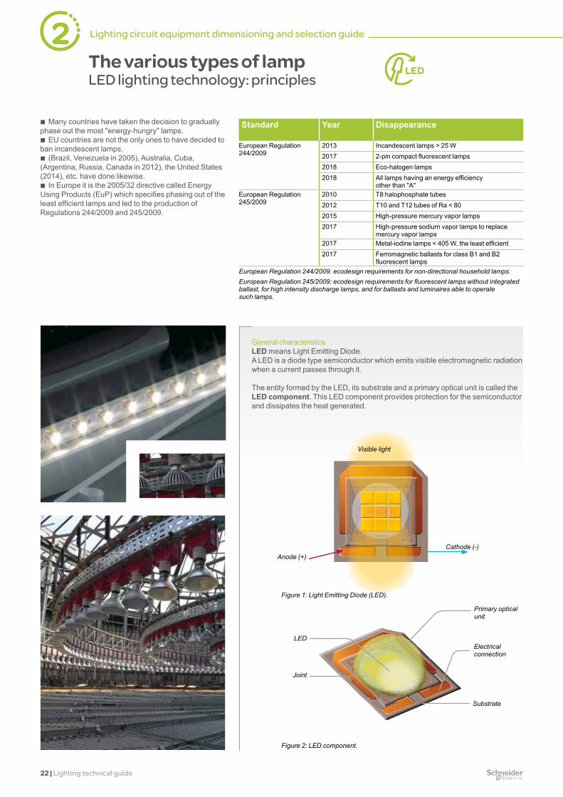
Visible light
Cathode (-)Anode (+)
Figure 2: LED component.
Primary optical unit
LED
Joint
Electrical connection
Substrate
Figure 1: Light Emitting Diode (LED).
The various types of lampLED lighting technology: principles
b Many countries have taken the decision to gradually phase out the most "energy-hungry" lamps.
b EU countries are not the only ones to have decided to ban incandescent lamps.
b (Brazil, Venezuela in 2005), Australia, Cuba, (Argentina, Russia, Canada in 2012), the United States (2014), etc. have done likewise.
b In Europe it is the 2005/32 directive called Energy Using Products (EuP) which specifies phasing out of the least efficient lamps and led to the production of Regulations 244/2009 and 245/2009.
Standard Year Disappearance
European Regulation 244/2009
2013 Incandescent lamps > 25 W2017 2-pin compact fluorescent lamps2018 Eco-halogen lamps2018 All lamps having an energy efficiency
other than "A"European Regulation 245/2009
2010 T8 halophosphate tubes2012 T10 and T12 tubes of Ra < 802015 High-pressure mercury vapor lamps2017 High-pressure sodium vapor lamps to replace
mercury vapor lamps2017 Metal-iodine lamps < 405 W, the least efficient2017 Ferromagnetic ballasts for class B1 and B2
fluorescent lampsEuropean Regulation 244/2009: ecodesign requirements for non-directional household lamps.European Regulation 245/2009: ecodesign requirements for fluorescent lamps without integrated ballast, for high intensity discharge lamps, and for ballasts and luminaires able to operate such lamps.
General characteristicsLED means Light Emitting Diode.A LED is a diode type semiconductor which emits visible electromagnetic radiation when a current passes through it.
The entity formed by the LED, its substrate and a primary optical unit is called the LED component. This LED component provides protection for the semiconductor and dissipates the heat generated.
2 Lighting circuit equipment dimensioning and selection guide

Lighting technical guide | 23
Figure 7: Current versus time.
Current versus time – Luminaire starting
Time (s)
Cur
rent
(A)
-0.5 0 0.5 1 1.5 2 2.5-1.5
-1
-0.5
0
0.5
1
1.5
2
1 3
4
In the initial moments following luminaire power up, a significant transient current appears (up to about 250 times the rated current). The duration of this current due to the capacitors present in the driver is less than 1 ms for a single luminaire.
Figure 8: Current at switching on.
-1 0 1 2 3 4 5
x 10-3
-50
0
50
100
150
200
I/In
0°90°
Current (voltage phase equal to 0° and 90° at switching on)
Time (s)
It is also possible to obtain from LED suppliers printed circuit boards on which several LED components are already mounted.
The LED module is the assembly of one or more LED components with optical, mechanical and thermal elements.
A driver is an electronic device which can convert the electric power of a low-voltage AC electrical network into electric power appropriate for the LED luminaire (direct voltage and current).The driver may be external or integral with the luminaire.A driver can power one or more luminaires.
A LED luminaire is a complete system consisting of a LED module, a housing, an optical reflector, wiring, connectors, joints and a heat dissipation system (heat sink or fan).
LED lighting technology: Electrical characteristics
At power up, a variable current is demanded by the luminaires during the first second, and the current stabilizes as soon as rated operating conditions are reached.For luminaire starting, three transient states have been identified:
b State 1: inrush current. b State 2: driver starting. b State 3: powering the LED load.
These states are numbered on Figure 7. State 4 corresponds to steady-state operating conditions.
Figure 3: Printed circuit board with pre-fitted LEDs.
Figure 4: LED module.
Figure 5: Driver.
Figure 6: LED industrial luminaire.

24 | Lighting technical guide
Recommendation 1Type of connection / Equipment
Electrical connection Circuit breaker Earth leakage protection function
Control device
+
page 26 page 28 page 32 page 38 b The cross section of the
conductors is conventionally dimensioned by the steady-state current.
However, it must take into account the lamps' long starting and end-of-life overcurrents.
In three-phase circuits with lamps generating harmonic currents of order 24 and multiples, dimension the neutral conductor accordingly.
The circuit breaker rating should be dimensioned to protect the conductors without tripping:
v at power up, v during the lamp starting
and end-of-life phases. The choice of its tripping
curve and the number of downstream lamps can ensure continuity of service.
b The sensitivity of the earth leakage protection function should be dimensioned to protect:
v people from electric shock: 30 mA,
v property from fire: 300 or 500 mA.
b The rating (of the Vigi module or earth leakage protection switch) should be greater than or equal to that of the upstream circuit breaker (coordination).
For excellent continuity of service, choose a product that is:
v time-delayed (s type) for upstream protection against fire,
v "super immune" ("SI") for the protection of people.
b The tables at the end of the guide indicate, for each rating, the total lamp power that can be supplied by a modular power actuator.
b Application of these rules ensures that these control devices withstand:
v the inrush current at power up (compatible with their making capacity),
v the starting current (compatible with their thermal resistance).
The choice of product depends on: v the load type and power, v the number of operations per day, v the control application (push button,
PLC, etc.), v the inrush current and harmonic.
Type of lamp Risk of conductor overheating
Risk of nuisance tripping Risk of overload
Incandescent lampsBasic and halogen LV During the nominal
service life. At end of life
ELV halogen + ferromagnetic transformer
Harmonic leakage currents
ELV halogen + ferromagnetic transformer
High-frequency leakage currents generated by the electronic circuits
Fluorescent lampsNon-compensated ferromagnetic ballast
The starting overcurrent is short and is therefore not to be taken into account. Average at end of life
Harmonic leakage currents
Compensated ferromagnetic ballast
Series compensation
Parallel compensation
Harmonic leakage currents Series compensation:
Parallel compensation:
Electronic ballast High-frequency leakage currents generated by the electronic circuits
High-intensity discharge lampsNon-compensated ferromagnetic ballast
The long starting phase and end of life require that the electrical connections withstand twice the rated current.
Harmonic leakage currents Leakage current < 1 mA per lamp or luminaire
Compensated ferromagnetic ballast
Harmonic leakage currents
Electronic ballast High-frequency leakage currents generated by the electronic circuits
LED lampsPower supply (driver) for LED lighting
During the nominal service life
High-frequency leakage currents generated by the electronic circuits
None/low Medium High
2 Lighting circuit equipment dimensioning and selection guide
Lighting technical guide | 25
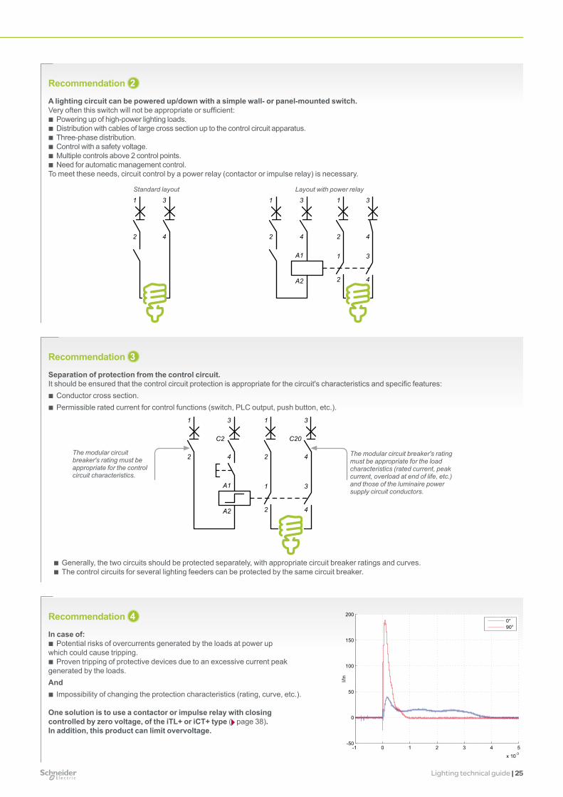
Recommendation 3
Separation of protection from the control circuit.It should be ensured that the control circuit protection is appropriate for the circuit's characteristics and specific features:
b Conductor cross section. b Permissible rated current for control functions (switch, PLC output, push button, etc.).
Recommendation 2
A lighting circuit can be powered up/down with a simple wall- or panel-mounted switch.Very often this switch will not be appropriate or sufficient:
b Powering up of high-power lighting loads. b Distribution with cables of large cross section up to the control circuit apparatus. b Three-phase distribution. b Control with a safety voltage. b Multiple controls above 2 control points. b Need for automatic management control.
To meet these needs, circuit control by a power relay (contactor or impulse relay) is necessary.
Recommendation 4
In case of: b Potential risks of overcurrents generated by the loads at power up
which could cause tripping. b Proven tripping of protective devices due to an excessive current peak
generated by the loads.And
b Impossibility of changing the protection characteristics (rating, curve, etc.).
One solution is to use a contactor or impulse relay with closing controlled by zero voltage, of the iTL+ or iCT+ type ( page 38). In addition, this product can limit overvoltage.
b Generally, the two circuits should be protected separately, with appropriate circuit breaker ratings and curves. b The control circuits for several lighting feeders can be protected by the same circuit breaker.
The modular circuit breaker's rating must be appropriate for the load characteristics (rated current, peak current, overload at end of life, etc.) and those of the luminaire power supply circuit conductors.
The modular circuit breaker's rating must be appropriate for the control circuit characteristics.
1 1
1
2 2
2
3 3
3
4 4
4
C2 C20
A1
A2
1
1
2
2
3 3
3
4 4
4
A1
A2
3
4
1
2
1
2
Standard layout Layout with power relay
-1 0 1 2 3 4 5
x 10-3
-50
0
50
100
150
200
I/In
0°90°

26 | Lighting technical guide
Selection of electrical distribution systemsPrinciples for selection of cables and prefabricated busbar trunking
Cable cross section dimensioning factors
Power connections
b The electrical power connections have the role of transporting energy from the electrical switchboard to the lighting loads.
b They can be formed of cables or prefabricated busbar trunking. b Where large areas have to be lit, they comprise a main circuit and branch circuits to
the luminaires. b Their selection depends on various constraints: v safety (insulation, little overheating, mechanical strength, etc.), v efficiency (limited voltage drop, etc.), v installation environment (location, installation procedure, temperature, etc.), v investment cost.
Length of electrical connectionsThe cable resistance causes a voltage drop proportional to the cable length and the current. It can cause malfunctions when the lamps are switched on or reduce the luminosity in steady state. The length of the circuits and the distributed power require an appropriate cable cross section.
Rated current of circuits b The total circuit power must be analyzed and calculated: v lamp power consumption, v any lamp ballast or transformer losses. b Depending on the type of load and any compensation, a power factor must be
applied. A poor power factor, for example, can double the current flowing through the circuits.
b For electrical connection dimensioning, one should allow for the fact that the lamps consume 1.5 to 2 times their rated current:
v at end of life for all lamps, v during the long starting phase for high-intensity discharge lamps.
Single-phase or three-phase distribution with or without neutral
In most buildings used for tertiary or commercial purposes, the lighting system is distributed via a single-phase circuit. To optimize the cabling, especially for high-power applications over large areas, three-phase distribution is sometimes used: 230 V between phase and neutral or between phases, or 400 V between phases for high-power lamps (2000 W).
L1
N
U = 230V
PE
NUU
U = 230 V ou 400 V
UL3
L1
L2
L3
PE
L1
L2
U
UU
U = 230V
L3
N
L1
L2
L3
N
L1
PE
L2
U = 230 V U = 230 V or 400 VU = 230 V
Installation procedureBuried or otherwise, on cable trays or embedded, etc.
Conductive materialCopper is less resistive but more expensive than aluminum.The use of aluminum is reserved for high-current electrical connections.
Ambient temperature1% to 2% derating per °C above the nominal temperature.
Loaded neutral correction factorIn the case of three-phase circuits supplying discharge lamps with electronic ballasts, harmonic currents of the third order and multiples of three are generated. They flow through the phase conductors and combine in the neutral cable, possibly causing an overload. The circuit must therefore be sized according to this harmonic content.
Mutual interference in the case of adjacent circuits
Type of insulating material
Derating factors to prevent overheating of electrical connections
Conductor cross section
Usual values b Power output per phase of a lighting circuit: v common values: 0.3 to 0.8 kW, v maximum values:
- 110 V: up to 1 kW, - 220 to 240 V: up to 2.2 kW. b Power factor: > 0.92 (compensated circuit or
electronic ballast). b Maximum permissible voltage drop (ΔU)
in steady state: v 3% for circuits of less than 100 m, v 3.5% tolerated above 200 m. b Cable cross section: v most commonly (< 20 m): 1.5 or 2.5 mm2, v very long (> 50 m) high-power circuit, to limit voltage
drops: 4 to 6 mm2, or even 10 mm2 (> 100 m).
Cables: fast dimensioning page 34
Optimized calculation: "CanBrass" software
2 Lighting circuit equipment dimensioning and selection guide

Lighting technical guide | 27
Type of electrical connections Cables Canalis busbar trunking
Criteria to be taken into account for selectionInstallation procedure (generating possible overheating) b
Mutual interference in the case of adjacent circuits b
Ambient temperature b b
Type of electric insulating material b
Loaded neutral correction factor (three-phase circuit with high harmonic distortion factor)
b b
Conductive material b
Length of electrical connection b b
Rated current of circuits b b Simplified selection according to the type of lamp
Halogen-free material b
Canalis prefabricated busbar trunkingThese systems meet the needs of all applications in commercial, tertiary and industrial buildings.
Advantages in every stage in the life of a buildingDesign
b Simplified electrical circuit diagram. b Direct selection of the model according to the type
and number of lamps. b Direct correspondence between the circuit breaker
rating and that of the duct (example at 35°C: KDP 20 A > 20 A .).
b Guaranteed performance irrespective of the installation (in accordance with the IEC 604279-2 standard).
b Suitable for all environments: IP55 standard, in conformity with sprinkler tests.
b Protects the environment: RoHS. b No halogen: releases no toxic fumes in case of fire.
Implementation b Ease of installation:
no risk of wiring error. b Can be installed by
unskilled personnel (connection by connectors, polarizing, etc.).
b Reduction in worksite time, control of completion times.
b Prefabricated, pretested: operates immediately on commissioning.
Operation and maintenance
b Quality of contacts of clamp type active conductors.
b Long service life, maintenance-free (up to 50 years).
b Continuity of service and safety: servicing can be performed on live lines.
b Significant reduction in radiated electromagnetic fields.
Changes in the building b Modular, hence
dismountable and reusable.
b Refitting of premises and their light fittings facilitated by the branch connections available at regular intervals.
b Legibility of the installation for servicing operations and upgrades.
Canalis: Fast dimensioning page 34
Optimized calculation: "CanBrass" software
Canalis KDP Canalis KBA Canalis KBB
Installation Type Flexible Rigid Very rigidInstallation procedure b Installed in suspended ceiling or
raised flooring b Attached to the building structure
(installation spacing up to 0.7 m)
b Suspended (installation spacing up to 3 m)
b Suspended (installation spacing up to 5 m)
Luminaire attachment to the duct No Yes YesPower circuits Quantity 1 1 1 or 2
Type b Single-phase b Three-phase
b Single-phase b Three-phase
b Single-phase b Three-phase b Single-phase + single-phase b Single-phase + three-phase b Three-phase + three-phase
Single-phase:2 conductors + PEThree-phase: 4 conductors + PELighting control circuit (0-10 V, Dali) - Optional OptionalRating 20 A 25 or 40 A 25 or 40 AProtection by fuses With tap-off KBC 16DCF.. With tap-off KBC 16DCF.. With tap-off KBC 16DCF..Tap-off spacing 1.2 - 1.35 - 1.5 - 2.4 - 2.7 – 3 m No tap-off or 0.5 - 1 - 1.5 m No tap-off or 0.5 - 1 - 1.5 m

28 | Lighting technical guide
7-15
t (s)
2-40.5-1.5
0.01-0.02
1.1-1.5 3-5
B C D
5-10 10-14 I / In
The tripping curve makes the protection more or less sensitive to:
b the inrush current at power up; b the overload current during the short (< 1 s) lamp
starting phase.
Overload protection
Selection of protection systemsCircuit breaker selection principles
iC60N circuit breaker Reflex iC60
b Protective devices are used to: v guard against fires that might be caused by a faulty electric circuit (short-circuit,
overload, insulation fault), v protect the workforce against electric shock in the event of indirect contact. b The choice of protective devices must be optimized to provide absolute protection
while ensuring continuity of service. b Although the protective devices are sometimes used as lighting circuit control units, it
is recommended to install: v separate control devices (switch, contactor, impulse relay page 38) v or an integrated control circuit breaker designed for lighting applications
(Reflex iC60 page 39) which withstands a larger number of switching operations.
Protection of electrical connectionsagainst short circuits and overloads
Choice of breaking capacity b The breaking capacity must be greater than or equal
to the presumed short-circuit current upstream of the circuit breaker.
b However, in the event of use in combination with an upstream circuit breaker limiting the current, this breaking capacity can possibly be reduced (cascading).
Choice of rating b The rating (In) is chosen above all to protect the
electrical connection: v for cables: it is chosen according to the cross section, v for Canalis prefabricated busbar trunking: it must be
simply less than or equal to the rating of the busbar trunking.
b Generally, the rating should be greater than the rated current of the circuits. But in the case of lighting circuits, to ensure excellent continuity of service, it is recommended that this rating correspond to about twice the rated current of the circuit (see section opposite), by limiting the number of lamps per circuit.
b The rating of the upstream circuit breaker must always be less than or equal to that of the control device located downstream (on-off switch, residual current circuit breaker, contactor, impulse relay, etc.).
Choice of tripping curve b Electricians always use the same curve for lighting
circuits: B or C depending on habits. b However, to prevent nuisance tripping, it may be
advisable to choose a less sensitive curve (2) (e.g. go from B to C)
Continuity of serviceSafety measures to guard against nuisance trippingNuisance tripping can be generated by:
b the inrush current which could be very high during circuit closing with LED luminaires,
b the overload current during the lamp starting phase, b and sometimes the harmonic current flowing through
the neutral of three-phase circuits (1).
Three solutions b Choose a circuit breaker with a less sensitive
curve: change from B curve to C curve or from C curve to D curve (2).
b Reduce the number of lamps per circuit b Start up the circuits successively, using time delay
auxiliaries on the control relays ( page 46 and example page 47).Under no circumstances may the circuit breaker rating be increased, as the electrical connections would then no longer be protected.
Reflex iC60The Reflex iC60 devices ( page 39) are integrated control circuit breakers which combine the following main functions in a single device:
b circuit breaker for cable protection,
b remote control by latched and/or impulse-type order,
b remote indication of product status,
b interface compatible with Acti 9 Smartlink and programmable logic controller (remote control and indications).
(1) In the particular case of three-phase circuits supplying discharge lamps with electronic ballasts, harmonic currents of the third order and multiples of three are generated and combined in the neutral conductor. The neutral cable must be sized to prevent it from overheating. However, the current flowing through the neutral cable may become greater than the current of each phase and cause nuisance tripping.(2) In the case of installations with very long cables in a TN or IT system, it may be necessary to add differential protection to protect human life. In all cases, the choice of curve must be confirmed by a design note.
Usual values
b Circuit breaker rating: value equal to twice the rated current of the circuit (6, 10, 13, 16 or 20 A)
b Curve: B or C depending on habits.
Circuit breaker: fast dimensioning page 34
Optimized calculation: "My Ecodial" software
2 Lighting circuit equipment dimensioning and selection guide

Lighting technical guide | 29
Number of lamps according to the circuit breaker rating and curve
A - Led technology
Use of circuit breakers b The new lighting technologies with electronic interfaces (ballasts, drivers) cause a
large transient inrush current at power up which could result in circuit breaker tripping. b These phenomena are especially significant with LED lighting. b Coordination curves between the number of LED luminaires and circuit breaker rating:
Depending on the control device used, the transient current peak may: b require derating of the circuit breaker according to the coordination curves between
the number of luminaires and the circuit breaker rating, when using conventional control devices: CT, TL (electromechanical control device),
b be reduced by using the following technologies: v softStart: implemented by a control integrated in the driver or by variable speed
controller, v controlled-action control contactor (iTL+, iCT+) (closing on zero crossing by the
voltage, only derating is linked to the lighting circuit's power factor.
These technologies make it possible to use the circuit breakers without derating due to the lamp technology.Example: Circuit rated power = 230 V AC x circuit breaker rating x power factor.
Maximum number of luminaires according to the circuit breaker rating and curveCircuit breaker rating
10 A 16 A 20 A
Unit power of the luminaire (W)
Curve B C D B, C, D with iCT+ or iTL+
B C D B, C, D with iCT+ or iTL+
B C D B, C, D with iCT+
10 15 30 48 - 22 44 69 - 32 63 98 -30 11 24 38 57 17 34 54 90 25 49 77 11050 8 17 27 41 12 25 39 66 18 35 56 8375 4 11 17 28 7 15 25 44 11 21 36 55150 - 5 9 13 2 7 12 22 4 9 18 28
C curve
D curve
B, C, D curve with iCT+ (or iTL+ up to 16 A)
0
10
20
30
40
50
60
30 50 75 150100
10
20
30
40
50
60
70
80
90
100
10 30 50 75 1500
20
40
60
80
120
100
10 30 50 75 150
Max
imum
num
ber o
f lum
inai
res
Power of a luminaire (W)
10 A rating
B curve
Power of a luminaire (W)
16 A rating
Power of a luminaire (W)
20 A rating

30 | Lighting technical guide
2 Lighting circuit equipment dimensioning and selection guide
Maximum number of lamps according to the circuit breaker rating and curveProducts iC60 (C curve)Type of lamp
10 A 16 A 25 A 40 A 63 AStandard incandescent lamps, LV halogen lamps, replacement mercury vapor lamps (without ballast)
40 W 28 46 70 140 20760 W 23 36 55 103 15275 W 29 31 46 80 121100 W 15 23 33 60 88
ELV 12 or 24 V halogen lampsFerromagnetic transformer
20 W 11 19 27 50 7550 W 8 12 19 33 5175 W 7 10 14 27 43100 W 5 8 10 22 33
Electronic transformer
20 W 47 74 108 220 33350 W 19 31 47 92 13775 W 15 24 34 64 94100 W 12 20 26 51 73
Fluorescent tubes with starter and ferromagnetic ballast1 tube without compensation (1)
15 W 16 26 37 85 12118 W 16 26 37 85 12120 W 16 26 37 85 12136 W 15 24 34 72 10840 W 15 24 34 72 10858 W 9 15 21 43 6865 W 9 15 21 43 6880 W 8 12 19 36 58115 W 6 9 12 24 38
1 tube with parallel compensation (2)
15 W 5 µF 11 19 24 48 7218 W 5 µF 11 19 24 48 7220 W 5 µF 11 19 24 48 7236 W 5 µF 11 19 24 48 7240 W 5 µF 11 19 24 48 7258 W 7 µF 8 12 19 36 5165 W 7 µF 8 12 19 36 5180 W 7 µF 8 12 19 36 51115 W 16 µF 4 7 9 17 24
2 or 4 tubes with series compensation
2 x 18 W 23 36 56 96 1484 x 18 W 12 20 29 52 822 x 36 W 12 20 29 52 822 x 58 W 8 12 20 33 512 x 65 W 8 12 20 33 512 x 80 W 7 11 15 26 412 x 115 W 5 8 12 20 31
Fluorescent tubes with electronic ballast1 or 2 tubes 18 W 56 90 134 268 402
36 W 28 46 70 142 21358 W 19 31 45 90 1342 x 18 W 27 44 67 134 2012 x 36 W 16 24 37 72 1082 x 58 W 9 15 23 46 70
(1) Circuits with non-compensated ferromagnetic ballasts consume twice as much current for a given power output. This explains the small number of lamps in this configuration.
(2) The total capacitance of the power factor capacitors in parallel on a circuit limits the number of lamps that can be controlled by a contactor. The total downstream capacitance of a modular contactor of rating 16, 25, 40 or 63 A should not exceed 75, 100, 200 or 300 μF respectively. Allow for these limits to calculate the maximum acceptable number of lamps if the capacitance values are different from those in the table.
The table is produced for C-curve circuit breakers: b for B-curve circuit breakers, the number of lamps should be reduced by 50%, b for D-curve circuit breakers, the number of lamps should be increased by 50%.
Number of lamps according to the circuit breaker rating and curve
B - Other technologies

Lighting technical guide | 31
Maximum number of lamps according to the circuit breaker rating and curve (cont.)Products iC60 (C curve)Type of lamp
10 A 16 A 25 A 40 A 63 ACompact fluorescent lamps
External electronic ballast
5 W 158 251 399 810 Infrequent use7 W 113 181 268 578
9 W 92 147 234 46311 W 79 125 196 39618 W 49 80 127 26126 W 37 60 92 181
Integral electronic ballast (replacing incandescent lamps)
5 W 121 193 278 568 8597 W 85 137 198 405 6219 W 71 113 160 322 49711 W 59 94 132 268 41118 W 36 58 83 167 25726 W 25 40 60 121 182
Low-pressure sodium vapor lamps with ferromagnetic ballast and external ignitorWithout compensation (1)
35 W 4 7 11 17 2955 W 4 7 11 17 2990 W 3 4 8 11 23135 W 2 3 5 8 12180 W 1 2 4 7 10
With parallel compensation (2)
35 W 20 µF 3 4 7 12 1955 W 20 µF 3 4 7 12 1990 W 26 µF 2 3 5 8 13135 W 40 µF 1 2 3 5 9180 W 45 µF 0 1 2 4 8
High-pressure sodium vapor lampsMetal-iodide lamps
Ferromagnetic ballast with external ignitor, without compensation (1)
35 W 12 19 28 50 7770 W 7 11 15 24 38150 W 3 5 9 15 22250 W 2 3 5 10 13400 W 0 1 3 6 101000 W 0 0 1 2 3
Ferromagnetic ballast and external ignitor, with parallel compensation (2)
35 W 6 µF 14 17 26 43 7070 W 12 µF 8 9 13 23 35150 W 20 µF 5 6 9 14 21250 W 32 µF 3 4 5 10 14400 W 45 µF 2 3 4 7 91000 W 60 µF 0 1 2 4 72000 W 85 µF 0 0 1 2 3
Electronic ballast 35 W 15 24 38 82 12370 W 11 18 29 61 92150 W 6 9 14 31 48
Note:High-pressure sodium vapor lampsFor the 10 A and 16 A B-curve ratings, the number of lamps should be reduced by 10% to limit unwanted magnetic tripping.

32 | Lighting technical guide
Norme CEI 479
Protection standard
+
Selection of protection systemsEarth leakage protection device selection principles
iID iC60N + Vigi iC60
b Earth leakage protection devices are used to: v guard against fires that might be caused by an electric circuit with an insulation fault, v protect the workforce against electric shock (direct or indirect contact). b The choice of protective devices must be optimized to provide absolute protection
while ensuring continuity of service. b The implementation of earth leakage protection on lighting circuits varies according
to standards, the earthing system and installation customs.
Protecting the installation against fires generated by a cable insulation faultProtecting peopleagainst electric shock
Choice of sensitivity b For protection against fire only: 300 mA. b For protection against electric shock: 30 mA.
Choice of rating b The rating must be greater than or equal to the total
consumption of the circuit. This consumption can be as much as twice the rated current of the lamps:
v in the case of discharge lamps, due to the long starting time (several minutes),
v higher consumption by lamps that have exceeded their nominal service life.
b The rating of the earth leakage protection function (Vigi module or earth leakage protection switch) should always be greater than or equal to the rating of the upstream circuit breaker.
Continuity of serviceSafety measures to guard against nuisance tripping
Choice of time delayProtective device discrimination
b For a two-level earth leakage protection system, the following are recommended: v upstream time-delayed earth leakage protection with sensitivity greater than or equal
to three times the downstream protection (for example, 100 or 300 mA s type protection), v one or more instantaneous 30 mA earth leakage protection devices downstream.
Super immune protection"SI" type super immune protection
b Compact fluorescent lamps and high-intensity discharge lamps with electronic ballast generate high-frequency currents (several kHz) that flow between conductors and earth in the ballast input filters and through stray capacitance in the installation.
b These currents (up to several mA per ballast) can trip standard earth leakage protection devices.
b To avoid such problems and maintain excellent continuity of service, "SI" type earth leakage protection is recommended.
"SI" type technology
b Red curve : international standard IEC 479 determines the limit current for earth leakage protection tripping according to the frequency. This limit corresponds to the current that the human body is capable of withstanding without any danger.
b Black curve : standard earth leakage protection devices are more sensitive to high-frequency currents than to 50/60 Hz.
b Green curve : "SI" type "super immune" protection devices are less sensitive to high-frequency disturbance while ensuring personal safety.
Tripping curve of a 30 mA earth leakage protection function
10 mA
1 mA10 Hz 100 Hz 1000 Hz 10000 Hz
100 mA
1000 mA
Super immune protection ("SI")
2 Lighting circuit equipment dimensioning and selection guide

Lighting technical guide | 33
T3T2T1
Selection of protection systemsPrinciple for selection of surge protective devices
PRF1 Master iPRD iQuick PRD
b Load protective devices are used to: v prevent fires which could be generated by the destruction of loads due to the effects
of lightning, v ensure the continuity of service of the most sensitive loads. b The choice of protective devices must be optimized to provide absolute protection
while ensuring continuity of service. b Implementation: surge protective devices are used at all levels of the electrical
installation, and on communication networks.
Choice of the type of surge protective deviceType 1Installed in the main electrical switchboard when the building is equipped with a lightning protection system.For more effective protection of loads, it should be combined with a type 2 surge protective device to absorb residual overvoltages.Type 2Installed in the main electrical switchboard, it is designed to discharge the currents generated by indirect lightning strokes and causing induced or conducted overvoltages on the power distribution network.Type 3Installed to complement the Type 2 surge protective device if the distance between the surge protective device and the load is >10 m.
Choice of surge protective device dimensioningType 1The discharge capacity is Iimp = 12.5 kA or 25 kA depending on building risk analysis.Type 2There are different discharge capacities for each of these categories (Imax = 20, 40, 65 kA (8/20 μs); this choice depends mainly on the exposure zone (moderate, average, high).Type 3They are designed to reduce overvoltage across the terminals of sensitive equipment.
Choice of breaking capacityThe surge protective device should be combined with a "circuit breaker or fuse" short-circuit protective device. This device will be chosen according to the installation’s short-circuit current.
The use of surge protective devices with an integrated disconnect circuit breaker ensures good coordination of the circuit breaker and surge protective device.
Exterior lightingGiven the widespread use of electronics in luminaires, it is recommended to establish a type 3 fine protection system at the level of each luminaire.
Continuity of servicePrecaution against nuisance tripping:In a TT system, a residual current device of the "SI" type or delayed "s" type should be installed upstream of the surge protective device. This type of device is immune to the risks of unwanted tripping due to lightning. The other solution is to install the residual current device downstream of the surge protective device.
Coordination between the protection system and the surge protective deviceGood coordination between the protection system and the surge protective device can prevent tripping on lightning waves and ensure isolation for the installation network at its end of life.
Surge protective device cascadingTerminal protection and fine protection
b To effectively protect an electrical installation, the discharge capacity of the surge protective devices to be installed should be determined according to the characteristics of the installation.
b Protection should be provided at the installation terminal (terminal protection) and, if necessary, near sensitive equipment (fine protection).
b The terminal protection system protects the whole installation, whereas the fine protection system protects only the loads with which it is associated.

34 | Lighting technical guide
Characteristics of the installation at 40°C, 230 V AC, Cos = 0.95 (1)Lighting power (kW)including any ballast losses
Rated current (A)
Maximum cable length (m) for a 3% voltage drop (the value shown is the average distance between the electrical switchboard and the lamps)
0.2 1 294 489 7830.4 2 147 245 391 5870.7 3 98 163 261 391 6521.3 6 49 82 130 196 326 5222.2 10 29 49 78 117 196 313 4893.5 16 18 31 49 73 122 196 3064.4 20 24 39 59 98 157 2455.5 25 31 47 78 125 1967.0 32 24 37 61 98 1538.7 40 29 49 78 12210.9 50 39 63 9813.8 63 50 78CableCross section of each conductor (mm2)
1.5 2.5 4 6 10 16 25
Circuit breakerRating (A) Recommended Twice the rated current of the lighting circuit
2 x 6 A = 13 or 16 A
Maximum (2)Cable with PVC type insulation
13 16 25 32 40 50 63
Other insulating material more efficient at high temperature.
16 20 32 40 50 63 80
From the main characteristics of the installation (lighting power, distance from electrical switchboard), these tables can be used to determine:
b the cross-section of the conductors on the power supply line for a voltage drop less than 3% at the lamps, whatever the installation method and insulating material used for the conductors,
b the circuit breaker rating for protection and continuity of service with a safety margin, whatever the type of lamps.
230 V AC single-phase copper cable
Infrequently used Recommended Acceptable Not recommended (high inrush currents) Risk of overheating/overloading the cable
Example described at bottom of page
(1) If the voltage or power factor is different, the lighting power and the cable length must be recalculated (the value of the rated current does not change):
b for a voltage of 110-115 V: divide the values by 2. b for a different power factor,
see the table below:
Cos Multiplying factor to be applied forPower Length
0.85 0.895 1.1180.5 0.526 1.9
(2) Maximum values not to be exceeded to guarantee cable protection.
Example of an open-plan office
Characteristics of the installation b 30 luminaires with 2 x 18 W 230 V single-phase fluorescent lamps. b Power factor (Cos ): 0.95. b Average distance from the switchboard: 60 m.
Calculations b Lamp power: 340 x 2 x 18 = 1080 W. b Ballast losses, estimated at 10% of the lamp power: i.e. 108 W. b Lighting power (P): 1080 + 108 = 1188 W = 1.2 kW; the next highest value in the table,
i.e. 1.3 kW, is selected. b Corresponding rated current (I = P/U Cos ): = 1188 W/(230 V x 0.95) = 5.4 A.
The next highest value in the table, i.e. 6 A, is selected. b Average distance from luminaires: 60 m; the next highest value in the table, i.e. 82 m,
is selected.Cable and protection values selected
b The recommended cable cross-section so as not to exceed a 3% voltage drop at the end of the line is therefore: 2.5 mm²
b Minimum recommended circuit breaker rating: 2 x 6 A = 12 A, equivalent to the next highest normalized value of 13 A or 16 A. This rating is effectively less than or equal to the maximum authorized rating (16 or 20 A) to ensure that the cable is protected.
2 Lighting circuit equipment dimensioning and selection guide
Quick dimensioning of electrical distribution and protection systemsCable cross-section, circuit breaker rating

Lighting technical guide | 35
Quick dimensioning of electrical distribution and protection systemsCable cross-section, circuit breaker rating
230 V AC three-phase copper cable between phase and neutral or 400 V AC between phases
Infrequently used Recommended Acceptable Not recommended (high inrush currents) Risk of overheating/overloading the cable
Example described at bottom of page (with correction of the values in the table taking into account a power factor of 0.85)
(1) If the voltage or power factor is different, the lighting power and the cable length must be recalculated (the value of the rated current does not change):
b for a different voltage, multiply the lighting power and the cable length by:
v 0.577 for a voltage of 230 V between phases, v 0.5 for a voltage of 110-115 V between phase and neutral. b for a different power factor, see the table below:
Cos Multiplying factor to be applied forPower Cable length
0.85 0.895 1.1180.5 0.526 1.9
(2) Maximum values not to be exceeded to guarantee cable protection.
Example of a warehouse
Characteristics of the installation b 39 x 70 W 230 V sodium vapor lamps with compensation, connected to a three-
phase circuit between phase and neutral. b Power factor (Cos ): 0.85. b Average distance from the switchboard: 120 m.
Calculations b Lamp power per phase: (39 x 70)/3 = 910 W. b Ballast losses per phase, estimated at 10% of the lamp power: i.e. 91 W. b Lighting power per phase (P): 910 + 91 = 1001 W = 1 kW. b Corresponding current (I = P/U Cos ): = 1001 W/(230 V x 0.85) = 5.1 A.
The next highest value in the table, i.e. 6 A, is selected. b Correction of the values in the table for the maximum cable length to take into
account the power factor: v 98 x 1.118 = 110 m, v 163 x 1.118 = 182 m
The next highest corrected value in the table after 120 m, i.e. 182 m, is selected.Cable and protection values selected
b The recommended cable cross-section per phase so as not to exceed a 3% voltage drop at the end of the line is therefore: 2.5 mm2.
b Minimum recommended circuit breaker rating: twice 6 A, i.e. 13 A or 16 A as a normalized value.This rating is effectively less than or equal to the maximum authorized rating (16 or 20 A ) to ensure that the cable is protected.
Characteristics of the installation Balanced three-phase circuit, at 40°C, Cos = 0.95 230 V AC between phase and neutral or 400 V AC between phases (1)Lighting power per phase (kW)including any ballast losses
Rated current per phase (A)
Maximum cable length (m)for a 3% voltage drop (the value shown is the average distance between the electrical switchboard and the lamps)
0.2 1 587 978 15650.4 2 294 489 783 11740.7 3 196 326 522 783 1304
1.3 x 0.895 = 1.2 6 98 110 163 182 261 391 652 10442.2 10 59 98 157 235 391 626 9783.5 16 37 61 98 147 245 391 6114.4 20 49 78 117 196 313 4895.5 25 63 94 157 250 3917.0 32 49 73 122 196 3068.7 40 59 98 157 24510.9 50 78 125 19613.8 63 99 155CableNeutral conductor cross-section equal to the phase cable cross-sectionCross section of each conductor (mm2)
1.5 2.5 4 6 10 16 25
Circuit breakerRating (A) Recommended Twice the rated current of the lighting circuit
2 x 6 A = 13 or 16 A
Maximum (2)
Cable with PVC type insulation
13 16 25 32 40 50 63
Other insulating material more efficient at high temperature
16 20 32 40 50 63 80

36 | Lighting technical guide
2 Lighting circuit equipment dimensioning and selection guide
Quick dimensioning of electrical distribution and protection systemsType of Canalis, circuit breaker rating
Step 1: choice of busbar trunking rating
Definition and layout of lighting lines
Location of luminaires on CANALIS lines
Definition of the type and number of luminaires (determination of total power)
Lighting power determined: • by type • by line • by distributed phase
Determination of the line protection characteristics (rating)
KBA/KBB 25 A KBA/KBB 40A
≤ 25 A ≤ 40 A
Study performed by the engineering office
KBBKBA

Lighting technical guide | 37
Quick dimensioning of electrical distribution and protection systemsType of Canalis, circuit breaker rating
Step 2: confirmation of the busbar trunking rating according to the length of the circuit and to the choice of circuit breaker rating
Single-phase Canalis 230 V AC busbar trunking
Characteristics of the installationat 35°C, Cos = 0.95 (1)
Lighting power (kW)including any ballast losses
Rated current (A)
Maximum busbar trunking length (m)for a voltage drop < 3% at the end of the busbar trunking.Lamps evenly spaced along the busbar trunking (most common case)
0.2 10.4 20.7 3 330 3751.3 6 165 188 3842.2 10 99 113 2313.5 16 62 70 1444.4 20 49 56 1155.5 25 45 927.0 32 728.7 40 5810.9 50 Overloaded busbar trunking13.8 63Prefabricated busbar trunkingType of busbar trunking Flexible
(KDP)Rigid (KBA or KBB)
Rating (A) 20 25 40Circuit breakerRating (A)
Recommended Twice the rated current of the lighting circuit
Max. 20 25 40
Infrequently used Recommended Acceptable Not recommended (high inrush currents) Risk of overheating/overloading the cable
Three-phase 230 V AC Canalis busbar trunking between phase and neutral or 400 V AC between phasesCharacteristics of the installationat 35°C, Cos = 0.95 230 V AC between phase and neutral or 400 V AC between phases (2)Lighting power per phase (kW) including any ballast losses
Rated current per phase (A)
Maximum busbar trunking length (m)for a voltage drop < 3% at the end of the busbar trunking.Lamps evenly spaced along the busbar trunking (most common case)
0.2 10.4 20.7 3 661 7511.3 6 330 375 7692.2 10 198 225 4613.5 16 124 141 2884.4 20 49 113 2315.5 25 90 1847.0 32 1448.7 40 11510.9 50 Overloaded busbar trunking13.8 63Prefabricated busbar trunkingType of busbar trunking Flexible
(KDP)Rigid (KBA or KBB)
Rating (A) 20 25 40Circuit breakerRating (A) Recommended Twice the rated current of the lighting circuit
2 x 6 A = 13 or 16 A
Max. 20 25 40
(1) If the voltage or power factor is different, certain values in the table are to be recalculated (the value of the rated current does not change):
b for a voltage of 110-115 V: divide the values by 2, b for a different power factor, see the table below:
Cos Multiplying factor to be applied forPower Busbar trunking length
0.85 0.895 1.1180.5 0.526 1.9
(2) If the voltage or power factor is different, the lighting power and the busbar trunking length must be recalculated (the value of the rated current does not change):
b for a different voltage, multiply the lighting power and the busbar trunking length by: v 0.577 for a voltage of 230 V between phases, v 0.5 for a voltage of 110-115 V between phase and neutral. b for a different power factor, see the table below:
Cos Multiplying factor to be applied forPower Busbar trunking length
0.85 0.895 1.1180.5 0.526 1.9

38 | Lighting technical guide
Control devices b Their role is to control luminaire switching on and off. b Their technology allows a very large number of switching operations to be performed without adversely affecting their performance,
in normal operating conditions. b The installation of a control relay (impulse relay, contactor) allows: v remote control of a high-power lighting circuit, v easy performance of sophisticated functions (central control, timer, programming, etc.), v control of three-phase circuits. b The iCT+ and iTL+ are especially suitable for lamps with a high inrush current (LED lighting, lamps with electronic ballast).
Choice of control relay
Impulse relay Modular contactor Reflex iC60 integrated-control circuit breaker RCA iC60 remote control
iTL iETL iTL+ iCT iCT+ Reflex iC60 RCA iC60Type of power circuit architecture (modular/monobloc)
b Circuit protection is provided by a separate circuit breaker. b The control and power circuits are separate.
They can also relay the management devices ( page 50), which often have a limited switching capacity and do not allow multi-polar switching (phase/neutral or three-phase).
MonoblocThe circuit protection and power switching functions are incorporated in a single device
MonoblocThe circuit breaker combined with the RCA performs the circuit protection and power switching functions
Installation In enclosure and panel In enclosure and panel In enclosure and panelControl Number of
pointsMultiple Multiple Single (as standard) or multiple (with auxiliary) Single Multiple Multiple
Type Impulse-type, by push button Latched-type by switch (as standard) or impulse-type by push button (with auxiliary)
Pulse or latched Pulse or latched
Consumption 0 1 VA 1 to 2 VA 1 VA 5 VA 1 VARemote status indication
Protections Auxiliary on circuit breaker Incorporated b Incorporated b By MCB auxiliary
Control Auxiliary on contactor or impulse relay
– Auxiliary on contactor or impulse relay – Incorporated b Incorporated b By MCB auxiliary
Control circuit Push button, selector switch
12 to 230 V AC 230 V AC 12, 24, 48, 110, 230 V AC 230 V AC 230 V AC24/48 V AC/DC with iMDU auxiliary
230 V AC24/48 V AC/DC with iMDU auxiliary
PLC 6 to 130 V DC – 24 V AC, 24 V DC by TI24 iACT interface and iATL 24 V DC
– 24 V DC with Ti24 interface 24 V DC with Ti24 interface
Remote reclosing of the protective device
– – – – – Yes
Number of switching cycles per day (on average)
< 100 < 1000 < 100 < 1000 <10 1 to 2 on average
Flexibility of control By combining auxiliaries With relay circuitry By combining auxiliaries With relay circuitry Integrated auxiliary functions Integrated auxiliary functionsAdditional functions Many functions due to the use
of auxiliaries: b time delay b illuminated push-button
control b step-by-step control b signaling b latched-type control b centralized multi-level control b control by PLC
– Many functions due to the use of auxiliaries:
b time delay b illuminated push-button control b step-by-step control b signaling b latched-type control b centralized multi-level control b control by PLC
– Numerous functionalities incorporated: b choice of control order interpretation mode b control and indication interface compatible with 24 V DC programmable logic
controller standards b compatibility with Vigi iC60 residual current protection auxiliaries b control orders time delayed by time delay relays or PLCs
Numerous functionalities incorporated: b remote reclosing possible, following an electrical fault b choice of control order interpretation mode b control and indication interface compatible with 24 VDC programmable logic
controller standards b control orders time delayed by time delay relays or PLCs b compatibility with the auxiliaries of the iC60 and Vigi protection product offering (iOF,
iSD indications and iMN, iMX tripping, etc.)
Rating (commonest values in bold)
16 or 32 A 16 A 16, 25, 40, 63 A 20 A 10, 16, 25, 40, 63 A 1 to 63 A
Controlled power Several kW Several kW Several kWType of circuit controlled Single-phase (1 or 2 P) or
three-phase (3 or 4 P monobloc or in conjunction with iETL extension)
Single-phase (1P)Conducting neutral
Single-phase (1 or 2 P) or three-phase (3 or 4 P)
Single-phase (1P)Conducting neutral
Single-phase (2P) or three-phase (3 or 4P) Single-phase (1 or 2P) or three-phase (3 or 4P)
Number of lamps controlled pages 42 and 45 No derating: b 16 A cos φ
in steady-state conditions
pages 42 and 45 No derating: b 20 A cos φ
in steady-state conditions
pages 42 and 45 page 34
Favorite applications b Residential b Service sector and industrial
buildings (offices, corridors, shops, workshops, etc.)
b Residential b Service sector
buildings (hotels, hospitals)
b Service sector and industrial buildings (offices, open-space offices, warehouses, supermarkets, indoor car parks, etc.)
b Infrastructure (tunnels, outdoor car parks, public lighting, etc.)
b Residential b Service sector
buildings (hotels, hospitals)
b Service sector and industrial buildings (offices, open-space offices, warehouses, supermarkets, indoor car parks, etc.)
b Infrastructure (tunnels, outdoor car parks, public lighting, etc.)
b Infrastructure (tunnels, indoor/outdoor car parks, public lighting, etc.)
2 Lighting circuit equipment dimensioning and selection guide
Control devicesPrinciples for selection of modular remote control equipment

Lighting technical guide | 39
Impulse relay Modular contactor Reflex iC60 integrated-control circuit breaker RCA iC60 remote control
iTL iETL iTL+ iCT iCT+ Reflex iC60 RCA iC60Type of power circuit architecture (modular/monobloc)
b Circuit protection is provided by a separate circuit breaker. b The control and power circuits are separate.
They can also relay the management devices ( page 50), which often have a limited switching capacity and do not allow multi-polar switching (phase/neutral or three-phase).
MonoblocThe circuit protection and power switching functions are incorporated in a single device
MonoblocThe circuit breaker combined with the RCA performs the circuit protection and power switching functions
Installation In enclosure and panel In enclosure and panel In enclosure and panelControl Number of
pointsMultiple Multiple Single (as standard) or multiple (with auxiliary) Single Multiple Multiple
Type Impulse-type, by push button Latched-type by switch (as standard) or impulse-type by push button (with auxiliary)
Pulse or latched Pulse or latched
Consumption 0 1 VA 1 to 2 VA 1 VA 5 VA 1 VARemote status indication
Protections Auxiliary on circuit breaker Incorporated b Incorporated b By MCB auxiliary
Control Auxiliary on contactor or impulse relay
– Auxiliary on contactor or impulse relay – Incorporated b Incorporated b By MCB auxiliary
Control circuit Push button, selector switch
12 to 230 V AC 230 V AC 12, 24, 48, 110, 230 V AC 230 V AC 230 V AC24/48 V AC/DC with iMDU auxiliary
230 V AC24/48 V AC/DC with iMDU auxiliary
PLC 6 to 130 V DC – 24 V AC, 24 V DC by TI24 iACT interface and iATL 24 V DC
– 24 V DC with Ti24 interface 24 V DC with Ti24 interface
Remote reclosing of the protective device
– – – – – Yes
Number of switching cycles per day (on average)
< 100 < 1000 < 100 < 1000 <10 1 to 2 on average
Flexibility of control By combining auxiliaries With relay circuitry By combining auxiliaries With relay circuitry Integrated auxiliary functions Integrated auxiliary functionsAdditional functions Many functions due to the use
of auxiliaries: b time delay b illuminated push-button
control b step-by-step control b signaling b latched-type control b centralized multi-level control b control by PLC
– Many functions due to the use of auxiliaries:
b time delay b illuminated push-button control b step-by-step control b signaling b latched-type control b centralized multi-level control b control by PLC
– Numerous functionalities incorporated: b choice of control order interpretation mode b control and indication interface compatible with 24 V DC programmable logic
controller standards b compatibility with Vigi iC60 residual current protection auxiliaries b control orders time delayed by time delay relays or PLCs
Numerous functionalities incorporated: b remote reclosing possible, following an electrical fault b choice of control order interpretation mode b control and indication interface compatible with 24 VDC programmable logic
controller standards b control orders time delayed by time delay relays or PLCs b compatibility with the auxiliaries of the iC60 and Vigi protection product offering (iOF,
iSD indications and iMN, iMX tripping, etc.)
Rating (commonest values in bold)
16 or 32 A 16 A 16, 25, 40, 63 A 20 A 10, 16, 25, 40, 63 A 1 to 63 A
Controlled power Several kW Several kW Several kWType of circuit controlled Single-phase (1 or 2 P) or
three-phase (3 or 4 P monobloc or in conjunction with iETL extension)
Single-phase (1P)Conducting neutral
Single-phase (1 or 2 P) or three-phase (3 or 4 P)
Single-phase (1P)Conducting neutral
Single-phase (2P) or three-phase (3 or 4P) Single-phase (1 or 2P) or three-phase (3 or 4P)
Number of lamps controlled pages 42 and 45 No derating: b 16 A cos φ
in steady-state conditions
pages 42 and 45 No derating: b 20 A cos φ
in steady-state conditions
pages 42 and 45 page 34
Favorite applications b Residential b Service sector and industrial
buildings (offices, corridors, shops, workshops, etc.)
b Residential b Service sector
buildings (hotels, hospitals)
b Service sector and industrial buildings (offices, open-space offices, warehouses, supermarkets, indoor car parks, etc.)
b Infrastructure (tunnels, outdoor car parks, public lighting, etc.)
b Residential b Service sector
buildings (hotels, hospitals)
b Service sector and industrial buildings (offices, open-space offices, warehouses, supermarkets, indoor car parks, etc.)
b Infrastructure (tunnels, outdoor car parks, public lighting, etc.)
b Infrastructure (tunnels, indoor/outdoor car parks, public lighting, etc.)
Reflex iC60Solution for lighting control and protection applications
b Total safety of the installation. b Easy wiring. b Reduced consumption and heating in the switchboard. b Bistable solution. b Ready for interfacing with an Acti 9 Smartlink interface or integrated PLC.

40 | Lighting technical guide
N
L
NL
Simplification of the conventional cabling by using an impulse relayWithout control device
b Conventional cabling with two-way switches and changeover switch(es).
With impulse relay or impulse control device: Reflex iC60, RCA b Lower investment costs: v fewer cables, v small control circuit cross section, v faster installation (simplified cabling). b Upgradeable circuits: v easy to add a control point, v potential for adding auxiliaries (time delay, timer, centralized multi-level control, etc. page 46) and management functions. b Energy savings: v no power consumption in the control circuit (impulse relay) v automated management of switching on/off (movement detector, programmable time switch, dusk-to-dawn switch,
etc., page 50).
2 Lighting circuit equipment dimensioning and selection guide
Control devicesExample

Lighting technical guide | 41
+
Control devicesChoice of rating
iTL iCT
b The rating printed on the front of the products never corresponds to the rated current of the lighting circuit.
b The standards that determine the ratings do not take into account all the electrical constraints of the lamps due to their diversity and the complexity of the electrical phenomena that they create (inrush current, starting current, end-of-life current, etc.).
b Schneider Electric regularly conducts numerous tests to determine, for each type of lamp and each lamp configuration, the maximum number of lamps that a relay with a given rating can control for a given power.
iTL impulse relays and iCT contactors b The rating should be chosen according to the tables on the following pages. b The rating of the iTL and iCT must be equal to or greater than the protective device's
rating.
Reflex iC60 and RCA iC60 b The rating is determined by the cable characteristics in the same way as for the
circuit breaker. b The switching capacity is defined in the following tables.
Reflex iC60
RCA iC60
iTL+ iCT+
Ventilation spacer
Thermal dissipation b Modular contactors, due to their operating principle, constantly dissipate heat
(several watts) due to: v coil consumption, v power contact resistance.
Where several modular contactors are installed side by side in a given enclosure, it is therefore recommended to insert a side ventilation spacer at regular intervals (every 1 or 2 contactors). Heat dissipation is thus facilitated. If the temperature inside the enclosure exceeds 40°C, apply to the rating a derating factor of 1% per °C above 40°C.
b The impulse relays, Reflex iC60 and RCA, can usefully replace the modular contactors:
v they consume less energy and dissipate less heat (no permanent current in the coil). They require no spacer,
v depending on the application, they allow a more compact installation with less wiring.
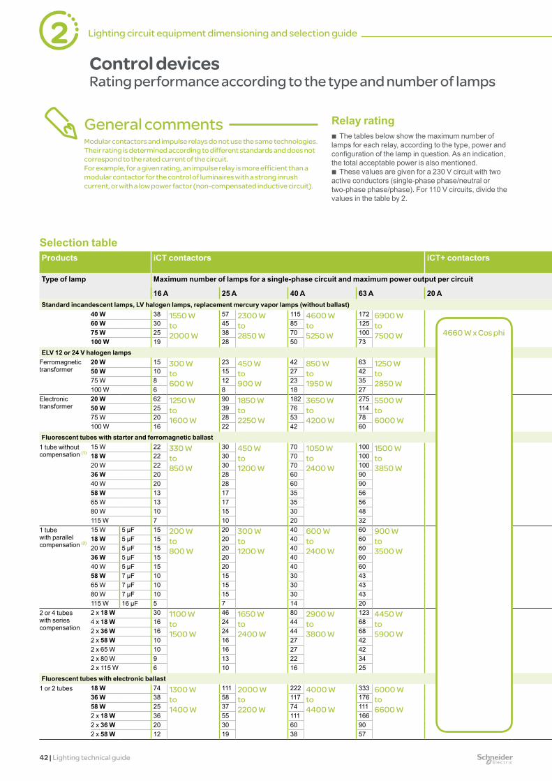
42 | Lighting technical guide
Relay rating b The tables below show the maximum number of
lamps for each relay, according to the type, power and configuration of the lamp in question. As an indication, the total acceptable power is also mentioned.
b These values are given for a 230 V circuit with two active conductors (single-phase phase/neutral or two-phase phase/phase). For 110 V circuits, divide the values in the table by 2.
General commentsModular contactors and impulse relays do not use the same technologies. Their rating is determined according to different standards and does not correspond to the rated current of the circuit.For example, for a given rating, an impulse relay is more efficient than a modular contactor for the control of luminaires with a strong inrush current, or with a low power factor (non-compensated inductive circuit).
Selection tableProducts iCT contactors iCT+ contactors iTL impulse relays iTL+
impulse relaysReflex iC60
Type of lamp Maximum number of lamps for a single-phase circuit and maximum power output per circuit Maximum number of lamps for a single-phase circuit and maximum power output per circuit
16 A 25 A 40 A 63 A 20 A 16 A 32 A 16 A 10 A 16 A 25 A 40 A 63 AStandard incandescent lamps, LV halogen lamps, replacement mercury vapor lamps (without ballast)
40 W 38 1550 W to 2000 W
57 2300 W to 2850 W
115 4600 W to 5250 W
172 6900 W to 7500 W
40 1500 W to 1600 W
106 4000 W to 4200 W
28 1120 W to 2175 W
46 1840 W to 2600 W
70 2800 W to 3600 W
140 5600 W to 6800 W
207 8280 W to 9800 W
60 W 30 45 85 125 25 66 23 36 55 103 15275 W 25 38 70 100 20 53 29 31 46 80 121100 W 19 28 50 73 16 42 15 23 33 60 88
ELV 12 or 24 V halogen lampsFerromagnetic transformer
20 W 15 300 W to 600 W
23 450 W to 900 W
42 850 W to 1950 W
63 1250 W to 2850 W
70 1350 W to 1450 W
180 3600 W to 3750 W
11 220 Wto500 W
19 380 Wto 800 W
27 540 Wto 1050 W
50 1000 Wto2200 W
75 1500 Wto3300 W
50 W 10 15 27 42 28 74 8 12 19 33 5175 W 8 12 23 35 19 50 7 10 14 27 43100 W 6 8 18 27 14 37 5 8 10 22 33
Electronic transformer
20 W 62 1250 W to 1600 W
90 1850 W to 2250 W
182 3650 W to 4200 W
275 5500 W to 6000 W
60 1200 W to 1400 W
160 3200 W to 3350 W
47 940 Wto1200 W
74 1480 Wto2000 W
108 2160 Wto 2600 W
220 4400 W to5100 W
333 6660 Wto7300 W
50 W 25 39 76 114 25 65 19 31 47 92 13775 W 20 28 53 78 18 44 15 24 34 64 94100 W 16 22 42 60 14 33 12 20 26 51 73
Fluorescent tubes with starter and ferromagnetic ballast1 tube without compensation (1)
15 W 22 330 W to 850 W
30 450 W to 1200 W
70 1050 W to 2400 W
100 1500 W to 3850 W
83 1250 W to 1300 W
213 3200 W to 3350 W
16 244 Wto647 W
26 390 Wto1035 W
37 555 Wto 1520 W
85 1275 Wto2880 W
121 1815 Wto4640 W
18 W 22 30 70 100 70 186 16 26 37 85 12120 W 22 30 70 100 62 160 16 26 37 85 12136 W 20 28 60 90 35 93 15 24 34 72 10840 W 20 28 60 90 31 81 15 24 34 72 10858 W 13 17 35 56 21 55 9 15 21 43 6865 W 13 17 35 56 20 50 9 15 21 43 6880 W 10 15 30 48 16 41 8 12 19 36 58115 W 7 10 20 32 11 29 6 9 12 24 38
1 tube with parallel compensation (2)
15 W 5 µF 15 200 W to 800 W
20 300 W to 1200 W
40 600 W to 2400 W
60 900 W to 3500 W
60 900 W 160 2400 W 11 165 Wto640 W
19 285 Wto960 W
24 360 Wto1520 W
48 720 Wto2880 W
72 1080 Wto4080 W
18 W 5 µF 15 20 40 60 50 133 11 19 24 48 7220 W 5 µF 15 20 40 60 45 120 11 19 24 48 7236 W 5 µF 15 20 40 60 25 66 11 19 24 48 7240 W 5 µF 15 20 40 60 22 60 11 19 24 48 7258 W 7 µF 10 15 30 43 16 42 8 12 19 36 5165 W 7 µF 10 15 30 43 13 37 8 12 19 36 5180 W 7 µF 10 15 30 43 11 30 8 12 19 36 51115 W 16 µF 5 7 14 20 7 20 4 7 9 17 24
2 or 4 tubes with series compensation
2 x 18 W 30 1100 W to 1500 W
46 1650 W to 2400 W
80 2900 W to 3800 W
123 4450 W to 5900 W
56 2000 W 148 5300 W 23 828 Wto1150 W
36 1296 Wto1840 W
56 2016 Wto2760 W
96 3456 Wto4600 W
148 5328 Wto7130 W
4 x 18 W 16 24 44 68 28 74 12 20 29 52 822 x 36 W 16 24 44 68 28 74 12 20 29 52 822 x 58 W 10 16 27 42 17 45 8 12 20 33 512 x 65 W 10 16 27 42 15 40 8 12 20 33 512 x 80 W 9 13 22 34 12 33 7 11 15 26 412 x 115 W 6 10 16 25 8 23 5 8 12 20 31
Fluorescent tubes with electronic ballast1 or 2 tubes 18 W 74 1300 W
to 1400 W
111 2000 W to 2200 W
222 4000 W to 4400 W
333 6000 W to 6600 W
80 1450 W to 1550 W
212 3800 W to 4000 W
56 1008 Wto1152 W
90 1620 Wto1798 W
134 2412 Wto2668 W
268 4824 Wto5336 W
402 7236 Wto8120 W
36 W 38 58 117 176 40 106 28 46 70 142 21358 W 25 37 74 111 26 69 19 31 45 90 1342 x 18 W 36 55 111 166 40 106 27 44 67 134 2012 x 36 W 20 30 60 90 20 53 16 24 37 72 1082 x 58 W 12 19 38 57 13 34 9 15 23 46 70
4660 W x Cos phi
2 Lighting circuit equipment dimensioning and selection guide
Control devicesRating performance according to the type and number of lamps

Lighting technical guide | 43
Selection tableProducts iCT contactors iCT+ contactors iTL impulse relays iTL+
impulse relaysReflex iC60
Type of lamp Maximum number of lamps for a single-phase circuit and maximum power output per circuit Maximum number of lamps for a single-phase circuit and maximum power output per circuit
16 A 25 A 40 A 63 A 20 A 16 A 32 A 16 A 10 A 16 A 25 A 40 A 63 AStandard incandescent lamps, LV halogen lamps, replacement mercury vapor lamps (without ballast)
40 W 38 1550 W to 2000 W
57 2300 W to 2850 W
115 4600 W to 5250 W
172 6900 W to 7500 W
40 1500 W to 1600 W
106 4000 W to 4200 W
28 1120 W to 2175 W
46 1840 W to 2600 W
70 2800 W to 3600 W
140 5600 W to 6800 W
207 8280 W to 9800 W
60 W 30 45 85 125 25 66 23 36 55 103 15275 W 25 38 70 100 20 53 29 31 46 80 121100 W 19 28 50 73 16 42 15 23 33 60 88
ELV 12 or 24 V halogen lampsFerromagnetic transformer
20 W 15 300 W to 600 W
23 450 W to 900 W
42 850 W to 1950 W
63 1250 W to 2850 W
70 1350 W to 1450 W
180 3600 W to 3750 W
11 220 Wto500 W
19 380 Wto 800 W
27 540 Wto 1050 W
50 1000 Wto2200 W
75 1500 Wto3300 W
50 W 10 15 27 42 28 74 8 12 19 33 5175 W 8 12 23 35 19 50 7 10 14 27 43100 W 6 8 18 27 14 37 5 8 10 22 33
Electronic transformer
20 W 62 1250 W to 1600 W
90 1850 W to 2250 W
182 3650 W to 4200 W
275 5500 W to 6000 W
60 1200 W to 1400 W
160 3200 W to 3350 W
47 940 Wto1200 W
74 1480 Wto2000 W
108 2160 Wto 2600 W
220 4400 W to5100 W
333 6660 Wto7300 W
50 W 25 39 76 114 25 65 19 31 47 92 13775 W 20 28 53 78 18 44 15 24 34 64 94100 W 16 22 42 60 14 33 12 20 26 51 73
Fluorescent tubes with starter and ferromagnetic ballast1 tube without compensation (1)
15 W 22 330 W to 850 W
30 450 W to 1200 W
70 1050 W to 2400 W
100 1500 W to 3850 W
83 1250 W to 1300 W
213 3200 W to 3350 W
16 244 Wto647 W
26 390 Wto1035 W
37 555 Wto 1520 W
85 1275 Wto2880 W
121 1815 Wto4640 W
18 W 22 30 70 100 70 186 16 26 37 85 12120 W 22 30 70 100 62 160 16 26 37 85 12136 W 20 28 60 90 35 93 15 24 34 72 10840 W 20 28 60 90 31 81 15 24 34 72 10858 W 13 17 35 56 21 55 9 15 21 43 6865 W 13 17 35 56 20 50 9 15 21 43 6880 W 10 15 30 48 16 41 8 12 19 36 58115 W 7 10 20 32 11 29 6 9 12 24 38
1 tube with parallel compensation (2)
15 W 5 µF 15 200 W to 800 W
20 300 W to 1200 W
40 600 W to 2400 W
60 900 W to 3500 W
60 900 W 160 2400 W 11 165 Wto640 W
19 285 Wto960 W
24 360 Wto1520 W
48 720 Wto2880 W
72 1080 Wto4080 W
18 W 5 µF 15 20 40 60 50 133 11 19 24 48 7220 W 5 µF 15 20 40 60 45 120 11 19 24 48 7236 W 5 µF 15 20 40 60 25 66 11 19 24 48 7240 W 5 µF 15 20 40 60 22 60 11 19 24 48 7258 W 7 µF 10 15 30 43 16 42 8 12 19 36 5165 W 7 µF 10 15 30 43 13 37 8 12 19 36 5180 W 7 µF 10 15 30 43 11 30 8 12 19 36 51115 W 16 µF 5 7 14 20 7 20 4 7 9 17 24
2 or 4 tubes with series compensation
2 x 18 W 30 1100 W to 1500 W
46 1650 W to 2400 W
80 2900 W to 3800 W
123 4450 W to 5900 W
56 2000 W 148 5300 W 23 828 Wto1150 W
36 1296 Wto1840 W
56 2016 Wto2760 W
96 3456 Wto4600 W
148 5328 Wto7130 W
4 x 18 W 16 24 44 68 28 74 12 20 29 52 822 x 36 W 16 24 44 68 28 74 12 20 29 52 822 x 58 W 10 16 27 42 17 45 8 12 20 33 512 x 65 W 10 16 27 42 15 40 8 12 20 33 512 x 80 W 9 13 22 34 12 33 7 11 15 26 412 x 115 W 6 10 16 25 8 23 5 8 12 20 31
Fluorescent tubes with electronic ballast1 or 2 tubes 18 W 74 1300 W
to 1400 W
111 2000 W to 2200 W
222 4000 W to 4400 W
333 6000 W to 6600 W
80 1450 W to 1550 W
212 3800 W to 4000 W
56 1008 Wto1152 W
90 1620 Wto1798 W
134 2412 Wto2668 W
268 4824 Wto5336 W
402 7236 Wto8120 W
36 W 38 58 117 176 40 106 28 46 70 142 21358 W 25 37 74 111 26 69 19 31 45 90 1342 x 18 W 36 55 111 166 40 106 27 44 67 134 2012 x 36 W 20 30 60 90 20 53 16 24 37 72 1082 x 58 W 12 19 38 57 13 34 9 15 23 46 70
Control devicesRating performance according to the type and number of lamps
b To obtain the equivalent values for the entire 230 V three-phase circuit, multiply the number of lamps and the maximum power output:
v by 3 (1.73) for circuits with 230 V between phases without neutral,
v by 3 for circuits with 230 V between phase and neutral or 400 V between phases.
Note: the lamp power ratings most commonly used are shown in bold.For power ratings not mentioned, use a proportional rule with the nearest values.
3680 W x Cos phi
Reflex iC60Solution for lighting control and protection applications
b Total safety of the installation. b Easy wiring. b Reduced consumption and heating in
the switchboard. b Bistable solution. b Ready to be connected with an
Acti 9 Smartlink or a PLC.

44 | Lighting technical guide
Selection table (cont.)Products iCT contactors iCT+ contactors iTL impulse relays iTL+ impulse
relaysReflex iC60
Type of lamp Maximum number of lamps for a single-phase circuit and maximum power output per circuit Maximum number of lamps for a single-phase circuit and maximum power output per circuit
16 A 25 A 40 A 63 A 20 A 16 A 32 A 16 A 10 A 16 A 25 A 40 A 63 ACompact fluorescent lamps
External electronic ballast
5 W 210 1050 W to 1300 W
330 1650 W to 2000 W
670 3350 W to 4000 W
Non testé 240 1200 W to 1450 W
630 3150 W to 3800 W
158 790 Wto962 W
251 1255 Wto1560 W
399 1995 Wto2392 W
810 4050 Wto4706 W
Infrequently used7 W 150 222 478 171 457 113 181 268 578
9 W 122 194 383 138 366 92 147 234 46311 W 104 163 327 118 318 79 125 196 39618 W 66 105 216 77 202 49 80 127 26126 W 50 76 153 55 146 37 60 92 181
Integral electronic ballast (replacing incandescent lamps)
5 W 160 800 W to 900 W
230 1150 W to 1300 W
470 2350 W to 2600 W
710 3550 W to 3950 W
170 850 W to 1050 W
390 1950 W to 2400 W
121 605 Wto650 W
193 959 Wto1044 W
278 1390 Wto1560 W
568 2840 Wto 3146 W
859 4295 Wto4732 W
7 W 114 164 335 514 121 285 85 137 198 405 6219 W 94 133 266 411 100 233 71 113 160 322 49711 W 78 109 222 340 86 200 59 94 132 268 41118 W 48 69 138 213 55 127 36 58 83 167 25726 W 34 50 100 151 40 92 25 40 60 121 182
Low-pressure sodium vapor lamps with ferromagnetic ballast and external ignitorWithout compensation (1)
35 W 5 270 W to 360 W
9 320 W to 720 W
14 500 W to 1100 W
24 850 W to 1800 W
Not tested, infrequently used
4 153 Wto253 W
7 245 Wto405 W
11 385 Wto792 W
17 595 Wto1198 W
29 1015 Wto2070 W
55 W 5 9 14 24 4 7 11 17 2990 W 3 6 9 19 3 4 8 11 23135 W 2 4 6 10 2 3 5 8 12180 W 2 4 6 10 1 2 4 7 10
With parallel compensation (2)
35 W 20 µF 3 100 W to 180 W
5 175 W to 360 W
10 350 W to 720 W
15 550 W to 1100 W
38 1350 W 102 3600 W 3 88 Wto169 W
4 140 Wto270 W
7 245 Wto450 W
12 420 Wto720 W
19 665 Wto1440 W
55 W 20 µF 3 5 10 15 24 63 3 4 7 12 1990 W 26 µF 2 4 8 11 15 40 2 3 5 8 13135 W 40 µF 1 2 5 7 10 26 1 2 3 5 9180 W 45 µF 1 2 4 6 7 18 0 1 2 4 8
High-pressure sodium vapor lampsMetal-iodide lamps
Ferromagnetic ballast with external ignitor, without compensation (1)
35 W 16 600 W 24 850 W to 1200 W
42 1450 W to 2000 W
64 2250 W to 3200 W
Not tested, infrequently used
12 416 Wto481 W
19 400 Wto750 W
28 980 Wto1350 W
50 1750 Wto2500 W
77 2695 Wto4000 W
70 W 8 12 20 32 7 11 15 24 38150 W 4 7 13 18 3 5 9 15 22250 W 2 4 8 11 2 3 5 10 13400 W 1 3 5 8 0 1 3 6 101000 W 0 1 2 3 0 0 1 2 3
Ferromagnetic ballast and external ignitor, with parallel compensation (2)
35 W 6 µF 12 450 W to 1000 W
18 650 W to 2000 W
31 1100 W to 4000 W
50 1750 W to 6000 W
34 1200 W to 1350 W
88 3100 W to 3400 W
14 490 Wto800 W
17 595 Wto1200 W
26 910 Wto2200 W
43 1505 Wto4400 W
70 2450 Wto7000 W
70 W 12 µF 6 9 16 25 17 45 8 9 13 23 35150 W 20 µF 4 6 10 15 8 22 5 6 9 14 21250 W 32 µF 3 4 7 10 5 13 3 4 5 10 14400 W 45 µF 2 3 5 7 3 8 2 3 4 7 91000 W 60 µF 1 2 3 5 1 3 0 1 2 4 72000 W 85 µF 0 1 2 3 0 1 0 0 1 2 3
Electronic ballast
35 W 24 850 W to 1350 W
38 1350 W to 2200 W
68 2400 W to 4000 W
102 3600 W to 600 W
38 1350 W to 2200 W
87 3100 W to 5000 W
15 525 Wto844 W
24 840 Wto1350 W
38 1330 Wto2100 W
82 2870 Wto4650 W
123 4305 Wto7200 W
70 W 18 29 51 76 29 77 11 18 29 61 92150 W 9 14 26 40 14 33 6 9 14 31 48
LED lampsWith driver 10 W 48 500 W
to 1400 W
69 700 W to 1950 W
98 1000 W to 3000 W
200 2000 W to 6200 W
69 700 W to 1950 W
98 1000 W to 3000 W
30 300 W to 850 W
44 450 W to 1250 W
71 700 W to 2000 W
108 1050 W to 3050 W
146 1450 W to 4150 W
30 W 38 54 77 157 54 77 24 34 55 83 11350 W 27 39 56 114 39 56 17 25 40 61 8375 W 17 25 36 73 25 36 11 15 24 37 50150 W 9 12 18 37 12 18 5 7 11 17 23200 W 7 9 15 31 9 15 - 6 10 15 20
(1) Circuits with non-compensated ferromagnetic ballasts consume twice as much current for a given power output. This explains the small number of lamps in this configuration.(2) The total capacitance of the power factor capacitors in parallel on a circuit limits the number of lamps that can be controlled by a contactor. The total downstream capacitance of a modular contactor of rating 16, 25, 40 or 63 A should not exceed 75, 100, 200 or 300 μF respectively.Allow for these limits to calculate the maximum acceptable number of lamps if the capacitance values are different from those in the table.
Note: Reflex iC60High-pressure sodium vapor lampsFor the 10 A and 16 A B-curve ratings, the number of lamps should be reduced by 10% to limit unwanted magnetic tripping.LED lampsB curve, the number of lamps should be reduced by 50%.D curve, the number of lamps should be increased by 50%.
4660 W x Cos phi
2 Lighting circuit equipment dimensioning and selection guide
Control devicesRating performance according to the type and number of lamps (cont.)

Lighting technical guide | 45
Selection table (cont.)Products iCT contactors iCT+ contactors iTL impulse relays iTL+ impulse
relaysReflex iC60
Type of lamp Maximum number of lamps for a single-phase circuit and maximum power output per circuit Maximum number of lamps for a single-phase circuit and maximum power output per circuit
16 A 25 A 40 A 63 A 20 A 16 A 32 A 16 A 10 A 16 A 25 A 40 A 63 ACompact fluorescent lamps
External electronic ballast
5 W 210 1050 W to 1300 W
330 1650 W to 2000 W
670 3350 W to 4000 W
Non testé 240 1200 W to 1450 W
630 3150 W to 3800 W
158 790 Wto962 W
251 1255 Wto1560 W
399 1995 Wto2392 W
810 4050 Wto4706 W
Infrequently used7 W 150 222 478 171 457 113 181 268 578
9 W 122 194 383 138 366 92 147 234 46311 W 104 163 327 118 318 79 125 196 39618 W 66 105 216 77 202 49 80 127 26126 W 50 76 153 55 146 37 60 92 181
Integral electronic ballast (replacing incandescent lamps)
5 W 160 800 W to 900 W
230 1150 W to 1300 W
470 2350 W to 2600 W
710 3550 W to 3950 W
170 850 W to 1050 W
390 1950 W to 2400 W
121 605 Wto650 W
193 959 Wto1044 W
278 1390 Wto1560 W
568 2840 Wto 3146 W
859 4295 Wto4732 W
7 W 114 164 335 514 121 285 85 137 198 405 6219 W 94 133 266 411 100 233 71 113 160 322 49711 W 78 109 222 340 86 200 59 94 132 268 41118 W 48 69 138 213 55 127 36 58 83 167 25726 W 34 50 100 151 40 92 25 40 60 121 182
Low-pressure sodium vapor lamps with ferromagnetic ballast and external ignitorWithout compensation (1)
35 W 5 270 W to 360 W
9 320 W to 720 W
14 500 W to 1100 W
24 850 W to 1800 W
Not tested, infrequently used
4 153 Wto253 W
7 245 Wto405 W
11 385 Wto792 W
17 595 Wto1198 W
29 1015 Wto2070 W
55 W 5 9 14 24 4 7 11 17 2990 W 3 6 9 19 3 4 8 11 23135 W 2 4 6 10 2 3 5 8 12180 W 2 4 6 10 1 2 4 7 10
With parallel compensation (2)
35 W 20 µF 3 100 W to 180 W
5 175 W to 360 W
10 350 W to 720 W
15 550 W to 1100 W
38 1350 W 102 3600 W 3 88 Wto169 W
4 140 Wto270 W
7 245 Wto450 W
12 420 Wto720 W
19 665 Wto1440 W
55 W 20 µF 3 5 10 15 24 63 3 4 7 12 1990 W 26 µF 2 4 8 11 15 40 2 3 5 8 13135 W 40 µF 1 2 5 7 10 26 1 2 3 5 9180 W 45 µF 1 2 4 6 7 18 0 1 2 4 8
High-pressure sodium vapor lampsMetal-iodide lamps
Ferromagnetic ballast with external ignitor, without compensation (1)
35 W 16 600 W 24 850 W to 1200 W
42 1450 W to 2000 W
64 2250 W to 3200 W
Not tested, infrequently used
12 416 Wto481 W
19 400 Wto750 W
28 980 Wto1350 W
50 1750 Wto2500 W
77 2695 Wto4000 W
70 W 8 12 20 32 7 11 15 24 38150 W 4 7 13 18 3 5 9 15 22250 W 2 4 8 11 2 3 5 10 13400 W 1 3 5 8 0 1 3 6 101000 W 0 1 2 3 0 0 1 2 3
Ferromagnetic ballast and external ignitor, with parallel compensation (2)
35 W 6 µF 12 450 W to 1000 W
18 650 W to 2000 W
31 1100 W to 4000 W
50 1750 W to 6000 W
34 1200 W to 1350 W
88 3100 W to 3400 W
14 490 Wto800 W
17 595 Wto1200 W
26 910 Wto2200 W
43 1505 Wto4400 W
70 2450 Wto7000 W
70 W 12 µF 6 9 16 25 17 45 8 9 13 23 35150 W 20 µF 4 6 10 15 8 22 5 6 9 14 21250 W 32 µF 3 4 7 10 5 13 3 4 5 10 14400 W 45 µF 2 3 5 7 3 8 2 3 4 7 91000 W 60 µF 1 2 3 5 1 3 0 1 2 4 72000 W 85 µF 0 1 2 3 0 1 0 0 1 2 3
Electronic ballast
35 W 24 850 W to 1350 W
38 1350 W to 2200 W
68 2400 W to 4000 W
102 3600 W to 600 W
38 1350 W to 2200 W
87 3100 W to 5000 W
15 525 Wto844 W
24 840 Wto1350 W
38 1330 Wto2100 W
82 2870 Wto4650 W
123 4305 Wto7200 W
70 W 18 29 51 76 29 77 11 18 29 61 92150 W 9 14 26 40 14 33 6 9 14 31 48
LED lampsWith driver 10 W 48 500 W
to 1400 W
69 700 W to 1950 W
98 1000 W to 3000 W
200 2000 W to 6200 W
69 700 W to 1950 W
98 1000 W to 3000 W
30 300 W to 850 W
44 450 W to 1250 W
71 700 W to 2000 W
108 1050 W to 3050 W
146 1450 W to 4150 W
30 W 38 54 77 157 54 77 24 34 55 83 11350 W 27 39 56 114 39 56 17 25 40 61 8375 W 17 25 36 73 25 36 11 15 24 37 50150 W 9 12 18 37 12 18 5 7 11 17 23200 W 7 9 15 31 9 15 - 6 10 15 20
(1) Circuits with non-compensated ferromagnetic ballasts consume twice as much current for a given power output. This explains the small number of lamps in this configuration.(2) The total capacitance of the power factor capacitors in parallel on a circuit limits the number of lamps that can be controlled by a contactor. The total downstream capacitance of a modular contactor of rating 16, 25, 40 or 63 A should not exceed 75, 100, 200 or 300 μF respectively.Allow for these limits to calculate the maximum acceptable number of lamps if the capacitance values are different from those in the table.
Note: Reflex iC60High-pressure sodium vapor lampsFor the 10 A and 16 A B-curve ratings, the number of lamps should be reduced by 10% to limit unwanted magnetic tripping.LED lampsB curve, the number of lamps should be reduced by 50%.D curve, the number of lamps should be increased by 50%.
Control devicesRating performance according to the type and number of lamps (cont.)
3680 W x Cos phi
Cos Pc (W)iTL+ iCT+
0.95 3500 44200.85 3120 39600.5 1840 2330
Where the standard contactors or impulse relays can only control a very limited number of lamps, the iCT+ and iTL+ are an alternative to be considered. They are especially suitable for lamps with a high inrush current consuming up to 16 A (iTL+) or 20 A (iCT+) in steady state (for example: lamps with ballast or ferromagnetic transformer). The following table shows the controllable power Pc according to the power factor. For high-intensity discharge lamps divide the power by 2 (long starting current).Example: how many compensated 58 W fluorescent tubes (power factor of 0.85) with ferromagnetic ballast (10% loss) can be controlled with a 20 A iCT+? Number of lamps N = controllable power Pc/(power output of each lamp + loss of ballast), i.e. in this case N = 3900/(58 + 10%) = 61. By comparison, a 16 A iCT is limited to 10 x 58 W tubes, a 25 A iCT to 15 lamps, and a 63 A iCT to 43 lamps.
iCT+, iTL+ !

46 | Lighting technical guide
Control auxiliariesOverview
iATEt iACT24 iATLc+s Mounting clipsiRTA
Control auxiliaries b These auxiliaries can perform a great variety of functions: v from the simplest (signaling, timer, illumination delay, etc.), v to the most sophisticated (centralized multi-level control, step-by-step control, etc.). b Moreover, some auxiliaries make it possible to overcome electrical disturbance
which may detract from satisfactory switching operation. b Schneider Electric has the most comprehensive and coherent product offering in
the market. All the auxiliaries in a family (modular contactor or impulse relay) are compatible with all the devices in that family.
b They are very easy to install thanks to their integral mounting clips which simultaneously provide electrical and mechanical connection.
Choice of auxiliariesor pre-auxiliary control devices
Function Pre-auxiliary impulse relay or impulse relay + auxiliary
Modular contactor + auxiliary
Reflex iC60 integrated-control circuit breaker
RCA iC60 remote control
Centralized control Centralized control (1 level) for a group of circuits while maintaining separate control of each of them.Example: control of a whole storey or room by room
iTLc or iTL + auxiliary iATLc
- Integrated Integrated
Centralized control (1 level) + signaling iTL + auxiliary iATLc+s - Integrated IntegratedCentralized control (2 levels)Example: control of a whole storey, a zone or room by room
iTL + auxiliary iATLc+c - Via PLC Via PLC
Impulse-type local control + latched-type centralized control
- iCT + auxiliary iACTc Integrated Integrated
Interface with PLC Allows control from Acti 9 Smartlink or a PLC
Auxiliary iATL24 Auxiliary iATL24 Reflex iC60 Ti24 version
Reflex iC60 Ti24 version
Signaling Remote signaling of lamp status (lit or extinguished)
iTLs or iTL + auxiliary iATLs
iCT + auxiliary iACTs Integrated Integrated
Timer Return to rest position after an adjustable time delay
Auxiliary iATEt + iTL Auxiliary iATEt + iTL Time delay relays (iRT) + PLC
Time delay relays (iRT) + PLC
Step-by-step control
Allows control of 2 circuits with a single control unit
Auxiliary iATL4 + 2 impulse relays iTL
Via PLC Via PLC Via PLC
Illuminated push button compensation
Allows fault-free control by illuminated push buttons
1 or more iATLz auxiliaries for each iTL
- Max. leakage current: 1.35 mA on Y2 input
Max. leakage current: 1.35 mA on Y2 input
Change in type of control
Operates on latched orders coming from a changeover contact (selector switch, time switch, etc.)
iTLm or iTL + auxiliary iATLm
Standard operation Yes Yes
Impulse-type local control + latched-type centralized control
Standard operation without auxiliary
Auxiliary iACTc + iCT Integrated Integrated
Time delay Illumination delay (see example on page 47).Allows the inrush current at the head of the network to be limited by powering the circuits in succession
Auxiliary iATEt + iTL Auxiliary iATEt + iCT Time delay relays (iRT) + Reflex iC60
Time delay relays (iRT) + RCA iC60
Disturbance suppressor
Can prevent disturbance generated on the electrical network at power off
Not applicable 1 iACTp auxiliary per iCT
Not applicable Not applicable
Voltage adaptation for control
Allows 24 V or 48 V AC/DC control Possible in V AC and V DC
b Possible in V AC b With auxiliary iMDU
in V DC
Possible with an auxiliary iMDU
2 Lighting circuit equipment dimensioning and selection guide

Lighting technical guide | 47
O
I
O
I
O
I
ExampleDimensioning an installation
Supermarket: main lighting circuits
Requirement General lighting Product enhancement Car park lightingCircuit Three-phase + neutral 230/400 V AC Single-phase 230 V AC Single-phase 230 V ACNumber of lines 18 (1 per department) 3 (1 per display) 10Number of lamps per line 45 luminaires with 56 W LED lamps Four 150 W metal-iodide lamps with
ferromagnetic ballast and parallel compensation
Nine 70 W high-pressure sodium vapor lamps with ferromagnetic ballast and parallel compensation
Electrical connectionsMain lines 18 60-m lines with Canalis KBA 25 A
(2 conductors + PE)Three 20-m lines with Canalis KBA 25 A 10 buried lines of 100 m with 10 mm2 cables
Branch to each luminaire 1 m of cables of 1.5 mm2 - 5 m of cables of 1.5 mm2
Monitoring/ControlProtectionResidual current circuit breaker
4P - 40 A - 300 mA - "SI" type 1 per group of 5 lines
2P - 25 A - 300 mA1 for all the 3 lines
2P - 40 A - 300 mA1 per group of 2 lines
Possible solutions 1 2 3 1 2 3 1 2 3Circuit breaker 4P
16 AC curve1 per line
4P 16 A C curve1 per line
Reflex iC604P16 AC curve1 per lineThe auxiliary centralized control (Y3) and indication (OF, SD) functions are integrated
2P 16 AC curve1 per line
2P 16 A C curve1 per line
Reflex iC602P16 AC curve1 per lineThe auxiliary centralized control (Y3) and indication (OF, SD) functions are integrated
2P 16 AB curve1 per line
2P 16 AB curve1 per line
Reflex iC602P16 AB curve1 per lineThe auxiliary centralized control (Y3) and indication (OF, SD) functions are integrated
Control devicesImpulse relay, contactor or integrated-control circuit breaker
Impulse relayITL2P32 A1 per line
ContactoriCT1P40 A1 per line
Impulse relayITL2P16 A1 per line
ContactoriCT2P16 A1 per line
Impulse relayITL1P16 A1 per line
ContactoriCT2P25 A1 per line
Control auxiliariesSignaling in the control panel
1 iATLs per impulse relay
1 iACTs per contactor
1 iATLc+s per impulse relay
1 iACTs per contactor
1 iATLc+s per impulse relay
1 iACTs per contactor
Centralized control - 1 iACTc per contactor
1 iACTc percontactor
Inrush current limited by successive illumination of groups of lines
1 ATEt on 6 groups of 3 lines with a time delay of 2 s between each group
Via PLC - -
Management devicesServo control by outside luminosity, timetable and calendar
- - 1 light sensitive switch IC2000P+
Successive illumination of 6 zones Use of one iATEt per group of lines to limit the inrush current.
Master control
Zone 0
Zone 1
Zone 5
t1
t5
Canalis KBB with DALI system
The winning solution for controlling and supplying power for supermarket lighting.

48 | Lighting technical guide
A
A
B
5
2
1
3
4
B
D
D
DC
C
2 Lighting circuit equipment dimensioning and selection guide
ExampleLighting management, a simple solution or a remote management solution
Zones Contracting authorities Power relays Type of lampPassageways Automatic by movement detector - LEDOffices Manual by local push button Impulse relay Fluorescent T5Car parks Automatic control by detection of the luminosity level and time
programmingContactor High pressure sodium
Simple solution
iTL remote control
Presence detector
IC light sensitive switch
iCT power relay circuitry

Lighting technical guide | 49
ExampleLighting management, a simple solution or a remote management solution
1 Zone 1 local lighting control
2 Zone 2 local lighting control
3 Centralized control of zone 1 and zone 2
4 Automatic control of outdoor lighting by presence detection
5 Automatic control by movement detection
Remote management solution
A Zone 1 luminaires
B Zone 2 luminaires
C Corridor zone luminaires
D Outdoor zone luminaires
Energy metering
iTL remote controlReflex iC60
Ethernet
Luminosity sensor
Modbus
Modbus
Zones Contracting authorities Power relays Type of lampPassageways Automatic by movement detector - LEDOffices Manual by local push button Impulse relay with remote
managementFluorescent T5
Car parks Automatic control by detection of the luminosity level and time programming
Reflex iC60 with remote management interface
High pressure sodium
Additional functions• Remote display of satisfactory operation (state of circuit breakers, contactors, etc.)• Fault indication• Luminaire operating time• Number of switching operations performed by power relays
Building Management System

50 | Lighting technical guide
Management devices
b These devices chiefly make it possible to optimize power consumption by managing lighting control according to various parameters:
v time, day or date, v a given limited duration, v movement or the presence of personnel, v level of luminosity, v the amount of natural light. b They can also improve everyday comfort through: v automation of the tasks of switching on/off, v manual or automatic adjustment of the illumination level.
MINIHP IC2000
Choice of management devices for energy savings and improved comfort
Products Potential energy savings
Functions Compatibility
Incandescent lamps
Fluorescent lamps
High-intensity discharge lamps
LED lamps(unit power 2 to 8 W)
IHElectromechanical time switches
50% b Hourly, daily or weekly b 1 or 2 circuits b With or without power reserve
(operation in the event of mains failure)
1000 W 600 to 700 W See Note 15 to 50 W
IHPDigital programmable time switches
50% b Daily, weekly or annual b 1 or 2 circuits b With or without conditional input b Switching interval: at least 1 min.
1000 to 2600 W 1000 to 2300 W 20 to 180 W
ICLight sensitive switch
30% b Controlled by: v astronomical clock (automatic
sunrise and sunset calculation) v luminosity detection (adjustable
from 2 to 2000 Lux) b With or without programmable clock
function
2300 to 3600 W 2300 to 3600 W 55 to 160 W
MINTimer
30% b 30 s to 1 h b 50% reduction of luminosity before
extinction of incandescent lamps with PRE auxiliary
2300 to 3600 W 2300 to 3600 WNot recommended for time delays of less than a few minutes
Not recommended for time delays of less than one hour
55 to 150 W
Note: IH/IHP/ICTo control lighting loads, whenever the power is significant and the type of lamp generates major inrush stress, it is recommended to combine a power actuator with each circuit:- a contactor- an impulse relay with its latched-type control auxiliary- a Reflex iC60or- a RCA iC60 (low rate of switching)
2 Lighting circuit equipment dimensioning and selection guide

Lighting technical guide | 51
Emergency lighting
b Emergency lighting is designed to eliminate or minimize public panic in the event of a serious problem such as a fire or an earthquake, and even merely a power cut.
b Suitable for all types and sizes of buildings (schools, hotels, shopping centers, hospitals, offices, shops, museums, etc.), Schneider Electric emergency lighting is essential to occupants' safety.
b The anti-panic devices give out a light that enables people to see where they are and avoid obstacles, while the signage units clearly show the way out of the premises. These products are mostly installed at a height.
Various technologies and characteristics b These luminaires have a light source consisting mainly of fluorescent lamps and
LEDs, a battery to supply power in the event of a mains failure, and an electronic circuit board. These products are selected according to their luminous flux, IP, IK and battery life, illuminated continuously or only in the event of a power cut.
b They are also chosen for their maintainability: v standard units: tests are carried out manually or via a remote control, v Activa/self-test units: they are tested automatically and indicate their operating state
by means of colored LEDs, v Dardo/addressable units: they self-test and send the result over a pair of wires to a
centralizing control device.
Deactivating the luminaires b To prevent the batteries discharging when the installation is not used or in the event
of mains failure, the luminaires can be deactivated via: v a remote control (TBS) for Standard and Self-test units, v the Dardo Plus control unit for Addressable units.
The installation rules and diagrams are given for information only. They vary according to the country.Only the rules in force in each country must be observed.
Installation of evacuation BAES (signage)Install 1 emergency lighting unit (BAES) at each exit and each emergency exit, for each obstacle and change of direction to make it easier to evacuate the buildings safely.
b Maximum spacing between each unit on the routes according to the size of the evacuation pictogram.
b At a minimum height (out of reach of the public; generally 2 m). b Affix warning signs to the units. b Minimum luminous flux requirement. b Autonomy requirement in the event of mains failure (generally 1 h). b Required on all public premises.
Installation of anti-panic/ambience BAES b Min. lighting density (in lumens) per m2. b Even distribution throughout the premises. Often with a minimum number of units
per room. b Autonomy requirement in the event of mains failure (generally 1 h). b Required on all public premises.
Evacuation unit
Anti-panic unit

52 | Lighting technical guide
Basic rules b The cross-section and length of the cables must be appropriate to limit the voltage
drop to less than 3% at the end of the line in steady state (see tables on pages 34 to 37).
b The In rating of the standard protection and control switchgear must be far higher than the rated current of the lighting circuit:
v for the circuit breaker, take approximately twice the rated current of the circuit, v for the relay, always use the compatibility tables for each type of lamp and check
that its rating is always higher than that of the upstream circuit breaker (short circuit coordination).
b The In rating of the earth leakage protection device must be greater than or equal to that of the upstream circuit breaker.
Take the lamp ignition phase into account
Manage electronic ballast, transformer lamps or driver carefully
Problems b All the lamps have a very strong
starting current which breaks down as follows:
v an inrush current: peak of 10 to 250 times the rated current (In) at power up,
v followed by the starting current (for fluorescent or discharge lamps): possible overload of up to 2 In for several seconds or minutes depending on the type of lamp.
b This therefore gives rise to the following risks:
v conductor overheating, v circuit breaker nuisance tripping, v control device overloading.
Recommendation 1 b Limit the load on each circuit to between 300 and 800 W per 2-wire circuit for
standard 10/16 A 230 V AC equipment. b Increase the number of circuits to limit the number of lamps per circuit.
Recommendation n°2 b Use Canalis prefabricated busbar trunking systems for large service-sector or
industrial buildings.
Recommendation n°3 b In the case of time-delay installations, postpone the power up of each circuit by a
few tens of milliseconds to a few seconds.
Recommendation n°4 b To control lamps with ferromagnetic ballast or transformer, high-performance
control devices (iCT+ contactor or iTL+ impulse relay) should preferably be used instead of conventional relays to optimize the control of circuits of several kW up to 16 A.
Recommendation n°5 b Curve C or D circuit breakers should be preferred to curve B. Confirmation by design note required.
Problems b Electronic ballast lamps require
special attention (high-frequency leaks to earth, harmonics) to guard against certain risks:
v nuisance tripping of the earth leakage protection device,
v overheating/overloading of the neutral conductor in three-phase circuits,
v nuisance tripping of the 4-pole circuit breaker (neutral overload by third-order and multiple currents).
Recommendation n°1 b Create the shortest possible links between the lamps and the ballast in order to
reduce high-frequency interference and capacitive leaks to earth.
Recommendation n°2 b Provide adequate discrimination, install the correct earth leakage protection at
each level: v upstream:
- avoid instantaneous tripping 30 mA sensitivity, - use a time-delay protection: 100 or 300 mA, type s (selective). v use type "SI" ("Super immune") 30 mA instantaneous earth leakage protection
for the feeders.
Recommendation n°3 b In the case of three-phase circuits + neutral with third-order and multiple
harmonic contents > 33%: v oversize the cross-section of the neutral cable compared with that of the
phases, v check that the neutral current resulting from the sum of the harmonics is less
than the In rating of the 4-pole circuit breaker.
2 Lighting circuit equipment dimensioning and selection guide
Appendix Practical recommendations for the protection and control of lighting circuits

Lighting technical guide | 53
Save energy without increasing maintenance costs
Problems b Discharge lamps significantly reduce
energy consumption but create additional problems both for the user and with respect to their management:
v ignition is not instantaneous due to their starting time (a few seconds for fluorescent lamps to several minutes for high-intensity discharge lamps);
v repeated switching accelerates ageing by a factor of 3 to 5,
v their higher investment cost requires careful management.
Recommendation n°1 b To meet an instantaneous and/or temporary lighting requirement, an additional
circuit with halogen or LED lamps may be useful for premises lit by discharge lamps.
Recommendation n°2 b To limit the ageing of fluorescent lamps: set the timers or presence detectors to a
minimum value of 5 to 10 minutes.
Recommendation n°3 b Use LED lamps for frequent switching or when hot re-ignition is needed.
Recommendation n°4 b Set the lighting to remain on continuously in corridors and offices at peak times
rather than use presence detectors that will switch it on and off repeatedly.
Recommendation n°5 b Regularly, at the end of the lamps' average service life, replace all the lamps and
their ignitor for a given area to reduce maintenance costs.
Recommendation n°6 b Use the impulse relay or Reflex iC60 rather than the contactor to prevent energy
losses in the coils (a few Watts/relay).

54 | Lighting technical guide
Low pressure sodium
High pressure sodium
Fluorescent
High pressure mercury
Light-emitting diode
Halogen incandescent
Basic incandescent
Metal iodide, halide
years
2 Lighting circuit equipment dimensioning and selection guide
AppendixDefinition of light-related units
Candela (cd) b Old definition: luminous intensity (luminosity) of 1 candle. b Modern definition (standard international unit): luminous intensity of light at a wavelength of 555 nm over
1.46 10-3 W/steradian.
1/9 Lux1/4 Lux1 Lux1 m
1 lm
1 cd
1 sr
1 m2 1 m2 1 m2
2 m 3 m
Lumen (lm)Luminous flux of 1 cd in a 1 steradian cone (1 sphere/4π).Lux (lx)Illumination (quantity of light/m2) of 1 lumen/m2.Lighting efficiency (lm/W)Ratio of the luminous flux emitted to the electrical power consumed. The energy that is not converted into light is dissipated in the form of heat.The lighting efficiency decreases by 30% to 70% towards the end of the life of the lamp.
Progress in the performance of each technology over timeThe graph below illustrates:
b the low efficiency of incandescent lamps despite the halogen technology, b the obsolescence of the mercury technology, usefully replaced by sodium or metal iodide, b the good performance of fluorescent lamps, b the constant progress of light-emitting diodes, with a regular increase in performance (power LED, luminous
efficiency, CRI, etc.).

Lighting technical guide | 55
How to realize smart lighting control and energy saving?
Energy savingswith Lighting Control
Lighting can represent
25% to 50%
of energy consumption in buildings
depending on the business.
"Smart" lighting control is one way of quickly cutting the energy bill without detracting from essential comfort!

56 | Lighting technical guide
3 Lighting Control simple solutions
No
No
Yes
One control mode
Automatic control
Multiple control modes
Lighting variation control
Local control and centralized
Manual control only
Yes
NoNo
Yes
Yes
Yes
Yes
No
No
Lighting variation control
Safety voltage
Automatic
Remote management
Remote management and automatic
"Check that the types of protection (1P, 1P+N, 2P... and earth leakage protection) conform to the installation regulations in force in the country concerned"
Co
nte
nt

Lighting technical guide | 57
3 Lighting Control simple solutions
Emergency lighting
Time programming Management of the lighting period and bells in a school 58Managing the lighting of a convenience store or superette 60Lighting management for a car park of a large tertiary site 62Automatic control of public lighting according to sunrise and sunset times
64
Presence detection or movement
Lighting for a hotel lobby 66
Luminosity level Lighting management for an office space 68Optimizing lighting for the car park of a hotel 70Optimizing the lighting of a shop window 72
Automatic Improving management of a public lighting system in a town 74
1 level Lighting management for a house 84Renovation of the lighting for a Town Council 86Lighting management for a solicitor's office 88
More levels Lighting management for a university 90Local control + remote management
Ensuring the satisfactory functioning of loads critical for human safety
92
Individual control + general
Lighting management for a hotel room 94
Local control + automatic
Controlling power off for a hotel room by keycard 96
Manual control + automatic switch-off
Lighting management for an archive room 98Lighting management in a stairway, a corridor or a lobby 100Lighting management in a basement 102How to modernize the entrance of an apartment building 104
Automatic + local override
Optimizing the lighting of open office spaces 106Management of a large office building 108Ensuring the satisfactory functioning of loads critical for human safety
92
Impulse relay 230 V Lighting for a meeting room with remote reporting 80
Switch control Functional lighting for a hypermarket 76Selector switch control
Lighting for a storage warehouse 78
Impulse relay 24 V Lighting for a humid room 112
Remote control dimmers with push button
Lighting control for the exhibition halls of a museum 82
Local control + remote management
Controlling power off for a hotel room by keycard 96
Remote management + Automatic
Ensuring the satisfactory functioning of loads critical for human safety
92
Automating the lighting for an industrial workshop 110
Emergency lighting Emergency lighting in a public building: junior high school 114

Zoom on
Lighting control
58 |
Management of the lighting period and bells in a school
Favorite applications:
Q offices and educational institutions,
Q hotels, Q industry, Q housing, Q etc.
Customer needs Q The engineering departments want to optimize
the operating costs of the local body's educational institutions by achieving savings on lighting, and also achieve automatic actuation of the school bells at the appropriate time.
Q Override control of the lighting may be performed for maintenance or servicing purposes.
Proposed solution Q The use of the ITA makes it possible to: O limit the use of lighting by programming its
operation at times during which the classrooms and common areas must be lit,
O program bell ringing times, O have override control of the lighting by push
button. Q Duplication of the program in each educational
institution is performed by using a programming kit and the duplicate is transferred by means of a memory cartridge.
User/customer benefits Q Ease of programming: changes in time switch programming in case of special events or holiday
periods can be made using the programming tool on a computer; a memory cartridge allows the changes to be duplicated simply in each educational institution.
Q Reduced maintenance: thanks to GPS time reception and automatic summer time/winter time changing.
Q Lighting override control: a remote push button allows override control of the lighting for maintenance or servicing operations.
ITAEfficiency at your fingertips!
ISC00884EN

Ligh
ting
cont
rol
Diagram of the solution
| 59
> Time programming + GPS time reception = lighting and bell sounding at the right time
Text for specifications Q The lighting and bell will be activated by a programmable time switch. Q A programming key and programming kit will be used to create and copy the program to another time switch, or save it. Q No deviation from timetable thanks to synchronization performed by GPS clock. Q Override control of the lighting will be performed via a switch or push button.
Products used
iC60N
L
N
iC60N
iCTA1
A2
2
2 22
1 1 1
1 3
4
iC60N
21 6L 8 9N
1 2
141513
3
+
-
12-30 VDC
ITA
Ext.1
Ext.2
Product Description Unit ReferenceITA 4c Yearly programmable time switch, 4 channels 1 CCT15940
GPS or DCF GPS or DCF antenna (optional) 1 CCT15970 or CCT15960Programming kit and key Programming kit for PC and memory key (optional) 1 +1 CCT15950 and CCT15955iC60N MCB 1P 3
iCT Modular contactor 2P 1
GPS antenna
ISC00884EN

Zoom on
Lighting control
60 |
Managing the lighting of a convenience store or superette
Customer needs Q The manager of a convenience store wants to
automate its lighting system. Q His store comprises two separate lighting
areas: storage and sales. Q The lighting must be reduced: one luminaire out
of three during delivery, after closing and at cleaning time, while full lighting must be ensured during opening hours.
Q The layout of the shelves in the sales area could be reorganized, and the relocation of luminaires should be performed without works.
User/customer benefits Q Simplicity and speed of execution: from design to installation, no constraints, "Canalis" adapts to
all store configurations. Q Attractiveness: the white-colored (RAL 9003) Canalis components ensure consistency with the
colors of the luminaires. Q Cost saving: automation of the installation reduces electricity consumption. Q Flexibility: no works required when reorganizing the store or changing the sales area.
Favorite applications:
Q small stores, Q superettes, Q etc.
Proposed solution Q The system chosen is 25 A KBA Canalis busbar
trunking. Q The luminaires shall be installed directly under
Canalis KBA by means of KBA40ZFUW fasteners. Q An IHP+ 2c clock combined with contactors
ensures lighting scripting. Q Manual override control of the lighting will be
performed from the electrical switchboard. Q Alteration of the installation during
reorganization of the shelves will be simplified by the modularity and extreme ease of assembly and disassembly of the Canalis components.
KBA Rigid busbar trunking!
Canalis KBA
CA9SS038E

Ligh
ting
cont
rol
Diagram of the solution
| 61
Product Description Unit Reference
Canalis KBA 25 A straight element KBA25ED4303WCanalis KBA 25 A power supply box 1 KBA25ABG4WCanalis KBA Fasteners KBA40ZFUW
Canalis busbar trunking Tap-off connectors KBC10DCS101, 201, 301
iC60N C2 A 2P circuit breaker 1IHP+ 2c Programmable time switch with 2 output contacts 1 CCT15853iC60N C16 A 2P circuit breaker 3iCT 25 A 2P contactor 3
> Pre-cabling + time programming = lighting in the right place + lighting at the right time
Products used
Ext1Ext2
53IHP+2c
N L1 L2 L3 Canalis KBA
Text for specifications Q The use of a decentralized lighting electrical distribution architecture (prefabricated). Q Being able to reorganize the lighting layout without altering the electrical installation.
CA9SS038E

Zoom on
Lighting control
62 |
Lighting management for a car park of a large tertiary site
Customer needs Q Automate the lighting system of an outdoor car
park for a technology park according to the time and the position of the sun, without connecting a light sensor.
Q For cost saving reasons, after a certain time, only one lamp post out of two will remain lit.
Q The lighting system shall be programmed to operate only on working days.
Q Possibility of remote override control of the lighting if necessary for maintenance operations.
User/customer benefits Q Maintenance-free: the IC Astro light-sensitive switch offers the same functions as a regular light-
sensitive switch except that it does not require a light sensor. Accordingly, maintenance operations of cleaning, adjustment or replacement due to vandalism are unnecessary.
Q Energy savings: the lighting is switched on only during the period of activity of the site when the luminosity makes lighting of the car park necessary. The fact that there is no sensor prevents nonconforming lighting times due to fouling, damage to a sensor or the presence of plants.
Favorite applications:
Q public lighting, Q outdoor car parks, Q etc.
Proposed solution Q Use of the "IC Astro 2C" astronomical light-
sensitive switch allows: O car park lighting according to the position of the
sun, O control of 2 independent lighting circuits, O programming of lighting days and times, O the possibility of override control of the lighting
via a simple push button.
IC Astro 2CThe programmable astronomical light-sensitive switch!
IC Astro 2C
CA9SS006E

Ligh
ting
cont
rol
Diagram of the solution
| 63
Product Description Unit Reference
iC60N C10 A 1P+N circuit breaker 1
IC Astro 2C Programmable astronomical light-sensitive switch with 2 output contacts 1 CCT15243(1), CCT15244(2)
iC60N C63 A 3P+N circuit breaker 2
iCT 63 A 4P contactor 2(1) English, French, Spanish, Portuguese, Hungarian, Polish, Romanian, Czech, Slovak, Bulgarian, Greek, Slovenian, Serbian, Croatian.(2) English, French, Italian, German, Swedish, Dutch, Finnish, Danish, Russian, Ukrainian, Latvian, Lithuanian, Estonian, Turkish.
Text for specifications Q The outdoor lighting system is controlled by a time switch which allows for sunrise and sunset times and which requires no light
sensor. The lighting system may be inhibited on certain days.
> Astronomical clock + programming = guarantee of lighting duration
Products used
3 5
IC Astro 2C
Ext2
Ext1
3 5
C stroooC
Ext2
Ext1
CA9SS006E

Zoom on
Lighting control
64 |
Automatic control of public lighting according to sunrise and sunset times
Customer needs Q The mayor of the local body wants improved
operating dependability of public lighting in order to:
O improve the comfort and safety of his constituents,
O be able to control the lighting operating period. Q He also wants to reduce the lighting level by
50% so as to achieve energy savings from midnight to 5 am.
User/customer benefits Q Intuitive programming: the IC Astro 2C incorporates a backlit LCD screen display allowing
everyday programming to be performed. Q Program backup: internal backup of the program in the event of failure of the mains power supply. Q Use of a key via a PC for saving and the duplication of settings and programs in the various
cabinets. Q Simplified maintenance: no need of a luminosity detector, hence improved operating
dependability. Q Easier installation: screwless terminals for easy, fast connection.
Favorite applications:
Q public lighting, Q outdoor car parks, Q etc.
Proposed solution Q The use of an IC Astro 2C programmable
astronomical light-sensitive switch allows automatic switch-on and switch-off of the lighting according to sunrise and sunset times.
Q Two channels are used to be able to reduce the number of luminaires powered from midnight to 5 am (energizing of 1 or 2 phases).
Q Override control for each channel is provided by push buttons.
Q Given the installed capacity, relaying is provided by contactors.
IC Astro 2CThe programmable astronomical light-sensitive switch!
IC Astro 2C
ISC01572EN

Ligh
ting
cont
rol
Diagram of the solution
| 65
Product Description Unit Reference
iC60N C2 A 2P circuit breaker 1
iC60N C20 A 2P circuit breaker 2
IC Astro 2C Programmable astronomical light-sensitive switch with 2 output contacts 1 CCT15243(1), CCT15244(2)
iCT 25 A 2P contactor 2 A9C20732(1) English, French, Spanish, Portuguese, Hungarian, Polish, Romanian, Czech, Slovak, Bulgarian, Greek, Slovenian, Serbian, Croatian.(2) English, French, Italian, German, Swedish, Dutch, Finnish, Danish, Russian, Ukrainian, Latvian, Lithuanian, Estonian, Turkish.
Text for specifications Q Use of an astronomical light-sensitive switch with 2 independent channels, allowing automatic switch-on and switch-off of the
lighting according to sunrise and sunset times and geographic location, and without a luminosity detector. Q Program backup and duplication is performed on a programming key. Q Possibility of manual override control of the lighting for each channel by means of push buttons (or switches).
> Astronomical clock + 2 programmable channels = -30% on the energy bill
Products used
Ext1Ext2
53
IC Astro 2C
E
53
IC Ast2C22
ISC01572EN

Zoom on
Lighting control
66 |
Lighting for a hotel lobby
Customer needs Q Ensure lighting for people's movement if the
luminosity is insufficient. Q The lighting should automatically be
extinguished after a certain time, once the people have left.
Q It must be possible to switch on the lighting by remote override control to be able to check the condition of the lamps in daytime.
User/customer benefits Q Energy savings: lighting is ensured in the event of low luminosity and the presence of persons, and
this can optimize power consumption while ensuring the safe movement of people. It is also possible to adjust the time during which the lighting will remain lit after the last detection of a movement.
Q Comfort: automatic switching on without having to look for the lighting control.
Favorite applications:
Q hotels, Q residential
buildings, Q etc.
Proposed solution Q The Argus 360 allows detection of people in
movement. In the event of insufficient luminosity, the lighting comes on automatically for a given period.
Q Relaying by a contactor makes it possible to increase the control power.
Q A two-position wall switch, located at the reception desk for example, can be used to switch on the lighting by override control if necessary.
Argus Movement detection
Argus 360
CA9SS007E

Ligh
ting
cont
rol
Diagram of the solution
| 67
Product Description Unit Reference
iC60N C2 A 1P+N circuit breaker 1
iC60N C16 A 1P+N circuit breaker 1
Argus 360 360° movement detector 1 CCT56P002
iCT 25 A 1P+N contactor 1 A9C20732
Text for specifications Q The lighting system for an area is activated by movement detection and according to the luminosity. Q If necessary, the lighting can be switched on continuously by a remote control.
> Movement detection + luminosity measurement = safe movement
Products used
Argus 360
Changeover switch
CA9SS007E

Zoom on
Lighting control
68 |
Lighting management for an office space
Customer needs Q The manager of an office space needs to
organize the lighting layout for this space. Q He also wants to achieve energy savings by
implementing automatic switch-on or switch-off of the lighting according to the presence of people and the luminosity level.
Q Automatic extinguishing of each office shall be performed after a time delay in the absence of people.
Q The installation must be easily modifiable during rearrangement of the offices.
User/customer benefits Q Fewer cables: a single duct incorporates the power and the DALI communication buses for the
master and slave Argus detectors and DALI ballast (option T of the KBA product ranges). Q Communication between the master and slave Argus devices and override control push buttons
uses the power supply conductor (power line carrier). Q The prefabricated lighting electricity distribution system allows flexibility of installation for
arrangement or rearrangement of space, without altering the electrical structure.
Favorite applications:
Q small stores, Q superettes, Q etc.
Proposed solution Q The system chosen is Canalis busbar trunking
incorporating a DALI architecture without programming.
Q Automatic lighting is provided by master and slave DALI presence detectors, and adjustment of the constant luminosity level office by office is an integral function of the master Argus detectors.
Q These detectors are fastened directly to the busbar trunking or are simply connected to it according to the layout of the offices.
Q Information is transferred uniformly to all the ballasts connected to the master detector network.
Q Override control of the lighting is performed by push buttons connected to the (master) DALI detector.
Q Alteration of the installation will be easy thanks to the modularity and extreme ease of assembly and disassembly of the Canalis components.
KBA Rigid busbar trunking!
Canalis KBA
CA9SS039E

Ligh
ting
cont
rol
Diagram of the solution
| 69
Product Description Unit Reference
Canalis KBA 40 A straight element (with communication bus) KBA40ED4303TWCanalis KBA 40 A power supply box 1 KBA40ABG4TWCanalis KBA Fasteners KBA40ZFUW
Canalis busbar trunking Tap-off connectors 1 KBC16DCB21+KBC16ZT1
Canalis busbar trunking Connectors for Argus master detector 1 KBC16DCB40+KBC16ZT1Canalis busbar trunking Connectors for Argus slave detector 1 KBC10DCB40iC60N C16 A 1P+N circuit breaker 1
> Pre-cabling + presence detection = lighting in the right place + appropriate lighting
Products used
Text for specifications Q Decentralized DALI lighting system without programming. Q Simplification of office rearrangement.
Canalis KBA
From 1 to 6 luminaires
Argus master
Argus slave
Electronic ballast
CA9SS039E

Zoom on
Lighting control
70 |
Optimizing lighting for the car park of a hotel
IC100Light comes with the night!
Customer needs Q The hotel manager wants to optimize lighting
for a car park with a simple solution ensuring sufficient lighting irrespective of the natural luminosity level.
Proposed solution Q The use of an IC100 light-sensitive switch
allows automatic control of the car park lighting according to the level of outside luminosity and the threshold set on the light-sensitive switch.
User/customer benefits Q Customer safety: lighting is ensured in the event of low luminosity. Q Energy savings: precise setting of the lighting tripping threshold on the IC100 light-sensitive switch
can optimize the lighting period. Q Easy access to settings on the light-sensitive switch located in the electrical distribution
switchboard.
Favorite applications:
Q hotel, Q educational
institution, Q offices, Q etc.
IC100
ISC00881EN

Ligh
ting
cont
rol
Diagram of the solution
| 71
Product Description Unit Reference
IC100 Light-sensitive switch (supplied with a wall cell) 1 15482
iC60N C2 A 1P circuit breaker 1
iC60N C25 A 3P circuit breaker 1
iCT 40 A 3P contactor 1
> Luminosity measurement = sufficient lighting in all circumstances
Text for specifications Q Car park lighting is activated according to the luminosity. The light-sensitive switch must be combined with a wall cell. Q Power consumption exceeds 2300 W.
Products used
1
N L
2
42A2
A1
6
iC60N
L3
1 3 5
1 3 5
22 4 6
1
L2
L1
N
iC60N
iCT43 43IC100
Cell
ISC00881EN

Zoom on
Lighting control
72 |
Optimizing the lighting of a shop window
IC2000P+
ICLight comes with the night!
Customer needs Q The owner of the shop, set up in a shopping
mall, wants to light his shop window automatically when luminosity is low.
Q Also, he wants to achieve energy savings by automatic extinguishing of this lighting at closing time, and on non-working days.
Proposed solution Q The use of an IC2000P+ programmable
light-sensitive switch makes it possible to automatically control lighting of the shop window according to the level of outside luminosity and opening hours.
Q Non-working days can be programmed to inhibit lighting.
Q Remote override control possible by simple switch.
User/customer benefits Q Ease of installation: thanks to intuitive configuration. Q Flexibility of settings: has a luminosity level adjustable from 2 to 2100 Lux and an adjustable time
delay to prevent unwanted switch-on of the lighting in the event of a brief change in luminosity. Q Ease of use: override control of lighting by remote control switch. Automatic summer time/winter
time changing.
Favorite applications:
Q housing, Q shops, Q etc.
ISC00883EN

Ligh
ting
cont
rol
Diagram of the solution
| 73
L 1
L
3
1 1
22
5
N
N
4 6
iC60N iC60N
5IC2000P+
Product Description Unit Reference
IC2000P+ Programmable light-sensitive switch (supplied with a wall cell) 1 15483
iC60N C2 A 1P circuit breaker 1
iC60N C16 A 1P circuit breaker 1
> Luminosity measurement + time programming = value creation + savings
Text for specifications Q The light-sensitive switch must be combined with a wall cell. Q The operating period settings must be configured according to the shopping mall's opening hours. Q It must be possible to adjust the lighting tripping threshold according to the level of outside luminosity, from 2 to 2100 lux. Q It must be possible to override the lighting settings by remote control.
Cell
Products used
ISC00883EN

Zoom on
Lighting control
74 |
Improving management of a public lighting system in a town
Customer needs Q The quality of lighting is of prime importance for a
town. This installation provides management of public lighting and a power supply for the power sockets distributed over the public space to allow the holding of special events (markets, street entertainment).
Q The objective is to ensure the following functions by remote management:
O switching public lighting on and off, O energizing or de-energizing a power socket
circuit, O information on equipment operating states, so as
to plan repair operations, O remote restarting following an electrical fault. Q In the event of a remote management failure, a
function designed to ensure improved dependability of service is performed by a local PLC for switching the public lighting on and off.
User/customer benefits Q Simplicity: automated, secure solution for switching the power supply on and off, indications on the
front panel of the product and remote signaling. Q Safety: padlocking possible without any additional accessory. Q Continuity of service: enabling of automatic reclosing upon an electrical fault. Q Energy efficiency: no permanent consumption because the RCA iC60 remote control is a bistable
actuator.
Proposed solution Q The functional units are installed in street
cabinets along the roads, or in equipment rooms located near the area to be powered.
Q The RCA control device allows the PLC to switch off the power supply by actuating the iC60 device.
Q Each cabinet has a local automatic control system interfacing with the central system.
Q The RCA remote control is configured in 1-A mode to give priority to the management PLC and enable reclosing of the circuit breaker following a fault.
Favorite applications:
Q infrastructure, Q industry, large
tertiary, Q public lighting, Q power distribution, Q circuit load
shedding, Q etc.
RCA iC60Remote control!
With Ti24 interface
RCA iC60
A9 FA 02-01E

Ligh
ting
cont
rol
Diagram of the solution
| 75
90 A
10 A
400 V AC
400 V AC
400 V AC
230 V AC
24 V DC
24 V DC
24 V DC
iC60N20 A
Vigi300mA
iC60N20 A
Vigi300 mA
PLC
230 V AC
230 V AC
230 V AC
400 V AC
230 V AC
230 V AC
iC60N16 A
Vigi30 mARCA iC60 RCA iC60 RCA iC60
+ + + + + +
Products used
Text for specifications Q The lighting and power socket feeders must be powered by a modular circuit breaker combined with a remote control and an
earth leakage protection auxiliary. Q This circuit breaker is remote controlled automatically via a connection with a PLC without any additional interface. Q The state of the circuit breaker (open/closed) and the presence of an electrical fault must be indicated at the PLC level. Q After tripping of the protective device, remote reclosing is enabled.
Functional unit 1 Functional unit 2 Functional unit 3
Sector 1 lighting Sector 2 lighting Power socket enclosure
> Remote management + automatic control = quality of service + savings
Product Description Unit Reference
RCA iC60 230 V AC 50 Hz remote control with Ti24 4P interface 2 A9C70124
iC60N C20 A 4P circuit breaker 2 -
Vigi iC60 300 mA 4P earth leakage protection device 2 -
RCA iC60 230 V AC 50 Hz remote control with Ti24 2P interface 1 A9C70122
iC60N C16 A 2P circuit breaker 1 -
Vigi iC60 30 mA 2P earth leakage protection device 1 -
A9 FA 02-01E

Zoom on
Lighting control
76 |
Functional lighting for a hypermarket
Customer needs Q The Maintenance Department of a hypermarket
is to replace the T12 fluorescent tubes of the functional lighting system with far more efficient LED luminaires.
Q The customer does not wish to change the distribution architecture or the type of protection (long cable length), or increase the number of feeders in the electrical switchboard.
Q For a given illumination level, the installed capacity with LEDs is far smaller, but the current peaks generated at power up could possibly cause unwanted tripping of the B-curve protective circuit breakers.
User/customer benefits Q Reduction of current peaks within a ratio of 4 to 5 at power up, thanks to the use of iCT+ contactors,
which will make it possible to: O keep the protection system, O eliminate the risk of nuisance tripping, O limit the level of overvoltage generated at power up and "stress" the LED drivers less
(Soft Start concept).
iCT+The contactor!
iCT+
Favorite applications:
Q hypermarkets, Q shops, Q offices, Q etc.
Proposed solution Q Replace the standard contactors with iCT+
controlled-action control contactors (switching at zero voltage phase angle).
Q Keep the protective circuit breakers with the same characteristics (ratings, curves).
CA9SS011E

Ligh
ting
cont
rol
Diagram of the solution
| 77
Product Description Unit Reference
iC60N C10 A 1P+N circuit breaker 1
iC60N C16 A 1P+N circuit breaker 1
iCT+ Silent contactor 1 A9C15030
Text for specifications Q The replacement of the T12 fluorescent tube lighting system must not require: O a change of architecture, O a change in the characteristics of protective devices, O additional space in the electrical distribution switchboard.
> LED lighting + controlled-action control = limited capital cost + operating savings
Products used
iCT+
AfterNew installation with iCT+ and LED lamps
BeforeOld installation with CT and fluorescent tubes
2 kW fluorescent tubes 0.8 kW LED lamps
CA9SS011E

Zoom on
Lighting control
78 |
Lighting for a storage warehouse
Besoins clients Q Lighting control must be ensured by a
simple switch.
Q Obtain feedback on the lighting circuit state (ON or OFF).
Q The lighting power may be significant depending on the case.
User/customer benefits Q Reduced consumption and heating in the switchboard: use of the impulse relay avoids
permanent consumption by the coil of a contactor. Q Simplified control: the latched-control impulse relay makes it possible to use a simple switch. Q Lighting override control: the controls on the front panel of the product can be used to switch the
lighting on or off by override control for specific needs.
iTLmThe impulse relay!
iTLm iTL iATLm
Favorite applications:
Q educational institutions,
Q hotels, Q industry, Q infrastructure, Q etc.
Proposed solution Q The latched-control impulse relay iTLm is a
bistable relay that can be controlled by means of a changeover switch.
Q The iTLm opens or closes its contact according to the application of a voltage to the ON or OFF terminal. The voltage can be applied via a changeover contact of a simple switch, a time switch, etc.
CA9SS003E

Ligh
ting
cont
rol
Diagram of the solution
| 79
iTLmiTL iATLm
L3L2L1
iATLm
Product Description Unit Reference
iC60N C16 A 1P+N circuit breaker 1
iTLm Impulse relay with integral latched function 1 A9C34411
Variant for three-phase circuit
iC60N 1P+N C2 A circuit breaker 1
iC60N 3P+N C16 A circuit breaker 1
iTL 4P impulse relay 1 A9C30814
iATLm Impulse relay auxiliary with latched function 1 A9C15414
Text for specifications Q The lighting system for an area is activated by an impulse relay controlled by a simple two-position switch.
Lighting remote control must be able to be inhibited easily.
OFF OFFON ON
> Impulse remote control + switch = visibility of lighting status
Products used
Variant for three-phase lighting circuit
CA9SS003E

Zoom on
Lighting control
80 |
Lighting for a meeting room with remote reporting
iTLThe impulse relay!
iTL
Favorite applications:
Q housing, Q offices, Q hotels, Q etc.
Customer needs Q The meeting room's lighting must be able to be
controlled from several points. Q The receptionist must be able to check
switch-off when the room is not in use, to avoid any waste of energy if users have forgotten to turn off the light.
Proposed solution Q The iTL, iTLs impulse relay closes or opens the
circuit whenever a control pulse is applied. The pulse is generated by pressing one of the push buttons. All the push buttons are connected in parallel.
Q For the purpose of remote signaling, a lighting status report is produced by the signaling function of the iTLs.
User/customer benefits Q Space saving: the iTLs impulse relay saves space due to integration of the remote signaling
function. The total width is still 18 mm. Q Reduced consumption and heating: a "bistable" solution, which consumes no energy to hold the
lighting circuit in closed position. Q Comfort: the impulse relay offers continuous, silent operation compared with similar applications
using contactors. The distribution board can be installed in bedrooms, offices, etc. without any discomfort for the users.
iTLs
CA9SS001E
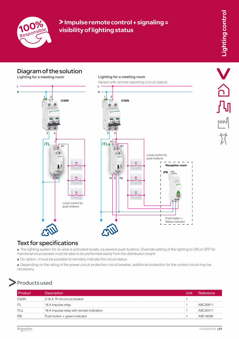
Ligh
ting
cont
rol
Diagram of the solution
| 81
Product Description Unit Reference
iC60N C16 A 1P+N circuit breaker 1
iTL 16 A impulse relay 1 A9C30811
iTLs 16 A impulse relay with remote indication 1 A9C32411
iPB Push button + green indicator 1 A9E18036
Text for specifications Q The lighting system for an area is activated locally via several push buttons. Override setting of the lighting to ON or OFF for
maintenance purposes must be able to be performed easily from the distribution board. Q On option, it must be possible to remotely indicate the circuit status. Q Depending on the rating of the power circuit protection circuit breaker, additional protection for the control circuit may be
necessary.
> Impulse remote control + signaling = visibility of lighting status
iPB
iTL iTLs
Local control by push buttons
Push button + Status indicator
Local control by push buttons
Reception room
Variant with remote reporting (circuit status)Lighting for a meeting roomLighting for a meeting room
Products used
CA9SS001E

Zoom on
Lighting control
82 |
Lighting control for the exhibition halls of a museum
Customer needs Q Control the main lighting system for three
exhibition halls separately and also by centralized actuation.
Q It must be possible to adjust the lighting so as to be able to lower the luminosity level and adapt lighting consumption to the needs.
Q A minimum of two lighting levels must be feasible in a simple manner.
User/customer benefits Q Ease of use: a single press on the external push buttons can call up the two lighting levels
memorized in the remote control dimmer. Q Clear indications on the front of the remote control dimmer: the indicator lamp on the control
push button on the front displays its status: in operation or in fault mode. Q Reliability: the remote control dimmers are provided with electronic protective devices. Q Energy savings: a mere 25% light variation can generate 20% energy savings.
Favorite applications:
Q offices and educational institutions,
Q hotels, Q industry, Q housing, Q etc.
Proposed solution Q The lighting system consists of fluorescent
tubes provided with electronic ballasts with 1-10 V control.
Q The solution is to separate the exhibition halls into three different thematic areas.
Q The use of three SCU10-SAE remote control dimmers will ensure centralized control of the three areas and allow memorizing of two lighting levels.
SCULight is under your control!
SCU10
CA9SS016E

Ligh
ting
cont
rol
Diagram of the solution
| 83
> Variation + central control = quality of lighting and operating comfort
Products used
Text for specifications Q The lighting system is implemented by fluorescent tubes with 1-10 V electronic ballasts. Q The system consists of several lighting areas, and each area can be switched on or off separately, with the possibility of
variation in the luminosity level. These operations shall be performed via simple push buttons. Q Master control by push buttons shall ensure: memorizing of two lighting scenarios, master control of switching on/off and
luminosity variation for all the areas.
Product Description Unit Reference
SCU10-SAE 1-10 V remote control dimmer with card having four digital inputs 3 CCTDD20012
iC60N C16 A 1P+N circuit breaker 1
iTR 230 V AC / 8-12 V AC – 4 VA transformer 1 A9A15213
LN
LN
N L N L N LLL NN L N
PB1PB2
1 3
iC60N
PB3
1 7
4 8
iTR
2 4
SCU10-SAE
0 V
21 3 4 0 + - 21 3 4 0 21 3 4 0
PB5PB4
+ - + -
Area A
Area B
Area C
1-10 V electronic ballast
1-10 V electronic ballast
1-10 V electronic ballast
12-30 VAC/DC
CA9SS016E

Zoom on
Lighting control
84 |
Lighting management for a house
Customer needs Q The lighting system must be able to be
turned on locally, by the residents.
Q It must be possible to switch off all the lighting areas by means of a centralized control in a single action, to ensure extinguishing of the whole house.
Q For practical reasons, all the lighting areas can also be switched on in a single action.
User/customer benefits Q Energy savings: centralized control allows extinguishing of all the rooms in the house to prevent
leaving rooms lit when there are no residents. Q Comfort: all the rooms in the house can also be switched on in a single action. Q Ease of installation: the small size (18 mm) of the iTLc is equivalent to that of a simple impulse relay.
iTLcThe impulse relay!
iTLc
Favorite applications:
Q housing, Q offices, Q etc.
Proposed solution Q The use of iTLc impulse relays allows both
local control of each room and centralized control of the whole house.
Q Centralized control is provided by ON/OFF push buttons, remote from all the rooms to be managed.
CA9SS008E

Ligh
ting
cont
rol
Diagram of the solution
| 85
Product Description Unit Reference
iC60N 1P+N C16 circuit breaker 2
iTLc Centralized-control impulse relay 2 A9C33811
Text for specifications Q Each lighting circuit is controlled locally via push buttons. Q All the lighting in the house is switched off via a single push button. Q All the lighting in the house is switched on via a single push button.
OFFON
> Impulse remote control + central control = energy savings + user comfort
Products used
iC60N iC60N
iTLc iTLc
Centralized control
CA9SS008E

Zoom on
Lighting control
86 |
Renovation of the lighting for a Town Council
Customer needs Q In order to optimize the existing lighting of a
Town Council and achieve savings, the engineering department wants to upgrade the installation, while keeping the local controls in place.
Q They also want to have a centralized control, located by the Town Council's reception desk, allowing all the offices, the Council meeting room and the reception to be extinguished in a single action.
User/customer benefits Q Energy savings and safety: the lighting for each area can be activated and deactivated locally by
the users. A push button located at the reception is connected to each iATLc auxiliary module for iTL and directly to each iTLc impulse relay. Result: all the impulse relays can respond simultaneously to central control orders.
Q Ease of connection: thanks to its integral centralized control function, the iTLc impulse relay allows savings of wiring and space. The total width is still 18 mm. The iATLc centralized control auxiliary is compatible with the standard iTL impulse relay to upgrade the existing installations. iATLc + iTL is equivalent to iTLc.
iATLcCentralized control!
iATLc iTL + iATLc
Favorite applications:
Q housing, Q offices, Q educational
institutions, Q etc.
Proposed solution Q For each office an iTLc will be used for lighting
control via push buttons. Q For lighting control in the lobby and meeting
rooms, for reasons of installed capacity, a 32 A impulse relay combined with an iATLc remote control auxiliary is necessary.
Q The iTLc and iATLc allow centralized control via a push button installed by the reception desk which extinguishes all the building's lighting.
CA9SS010E

Ligh
ting
cont
rol
Diagram of the solution
| 87
Product Description Unit Reference
iC60N C2 A 2P+N circuit breaker 1
iC60N 2P+N C10 A circuit breaker 2
iC60N 2P+N C20 A circuit breaker
iTL 32 A impulse relay 1 A9C30831
iTLc Centralized-control impulse relay 1 A9C33811
iATLc Centralized control auxiliary 1 A9C15404
Text for specifications Q A single push button must be able to extinguish all the building's lighting. Q The "centralized control" function must be compatible with the volume available in the existing switchboard (additional space
requirements limited insofar as possible).
> Impulse remote control + local and central control = energy savings + ease of use
Products used
iTL32 A
iTLc iATLciA
Centralized control by push button
CA9SS010E

Zoom on
Lighting control
88 |
Lighting management for a solicitor's office
Customer needs Q Energy savings, safety: the lighting for each
area can be switched on or off locally by office workers.
Q The receptionist can switch all the lighting areas on (or off) from a central control, to prevent any waste of energy if users have forgotten to switch off the light.
Q Signaling of the lighting status is necessary for the reception desk (indicator lit if one of the offices is illuminated).
User/customer benefits Q Energy savings: centralized remote control allows all the office and meeting room lights to be
extinguished and prevents leaving the lighting on in rooms when closing the solicitor's office. Q Comfort: an indicator lamp can indicate that an office or meeting room is lit. Local push buttons
actuate impulse relays individually for each lighting circuit.
Favorite applications:
Q offices, Q educational
institutions, Q hotels, Q etc.
Proposed solution Q The combination of iATLc+s auxiliaries for iTL
impulse relays allows both local control of each office, centralized control, and signaling of the lighting status.
Q Centralized control is provided by ON/OFF push buttons, remote from all the offices to be managed.
Q Signaling is achieved by mounting in series the auxiliary signaling contact of each impulse relay.
iATLc+sCentralized control!
iTL+iATLc+s
CA9SS009E

Ligh
ting
cont
rol
Diagram of the solution
| 89
> Impulse remote control + central control = energy savings + ease of use
Products used
Text for specifications Q Each lighting circuit is actuated by local push buttons and via common switch-on and switch-off orders by push buttons
located at the reception level where a review of the situation is provided by a status indicator.
iATLc+s iATLc+s
21
iPB
iLL
3
on
off
4
Lighting status indicator
Centralized control by OFF push button
Centralized control by ON push button
NL
Lighting ON indicator
Local control of the circuit by push buttons
Local control of the circuit by push buttons
Product Description Unit Reference
iC60N C2 A 1P+N circuit breaker 1
iC60N C10 A 1P+N circuit breaker 2
iTL Impulse relay 2 A9C30811
iATLc+s Centralized control + signaling 2 A9C15409
iIL Indicator lamp 1 A9E18320
iPB Double push button 1 A9E18035
CA9SS009E

Zoom on
Lighting control
90 |
Lighting management for a university
Customer needs Q There is a need to achieve savings on lighting
consumption for a university building of several stories.
Q Each room will be lit or extinguished separately. Q Manual extinguishing shall be feasible for each
story. Q The building will be switched off automatically
when the university is closed. Q The lighting in one room can be switched on
again during the period when the building is closed. It will remain switched on until the next extinguishing order sent by the time switch.
User/customer benefits Q Ease of installation: the centralized function incorporated in the impulse relay can reduce the
space requirement in the switchboard. Q Simple automatic control solution: the IHP+ 1c programmable time switch has a user-friendly
interface, an impulse control mode and a large number of possible switching operations.
Favorite applications:
Q office buildings, Q educational
institutions, Q etc.
Proposed solution Q The use of an iTLc impulse relay ensures
control of a lighting circuit via dedicated push buttons for each classroom.
Q It also makes it possible to receive a lighting extinguishing control order for the story.
Q One iATLc+c auxiliary for each story allows extinguishing of all the building's lighting.
Q The IHP+ 1c ensures automatic extinguishing of the entire building by impulse control.
iATLc+c
iATLc+cThe auxiliary centralized control module for impulse relays!
CA9SS018E

Ligh
ting
cont
rol
Diagram of the solution
| 91
> Area control + time programming = energy savings + flexibility of use
Products used
Text for specifications Q The solution must be optimized in terms of space requirements, with no programming requiring special skills. Q An automatic impulse control order for overall extinguishing must be generated when the building is closed and then repeated
every half-hour.
Product Description Unit Reference
iC60N C2 A 1P+N circuit breaker 2
iC60N C10 A 1P+N circuit breaker 4
iATLc+c Multiple-level centralized control auxiliary 2 A9C15410
iTLc 16 A centralized-control impulse relay 1 A9C33411
IHP+ 1c Programmable time switch 2 CCT15851
iATLc+c
iATLc+c
First storyLocal extinguishing control
First story
Ground floor
Ground floor Local extinguishing control
Building OFF
To other stories
Classroom C
Classroom A
Classroom D
Classroom B
CA9SS018E

Zoom on
Lighting control
92 |
Ensuring the satisfactory functioning of loads critical for human safety
Favorite applications:
Q commercial and industrial buildings,
Q etc.
Customer needs Q In an underground car park, ventilation and
lighting are critical for human safety. Q Any malfunction must immediately alert the
surveillance personnel. Q They must be able to diagnose the equipment
and restore it to operation very rapidly, remotely whenever possible, or by going to the site.
Q In the event of a malfunction of the automatic control system which manages them, these loads must continue to operate without interruption.
Proposed solution Q Thanks to Acti 9 Smartlink, all the final
distribution boards are connected directly to the site surveillance network.
Q The circuit breaker auxiliaries iOF+SD24 report any tripping and any deliberate opening.
Q The contactors and impulse relays receive switch-on and switch-off orders and report their status.
Q Selector switches on the front panel of the switchboards allow maintenance personnel to take over control of the automatic system to manage the contactors and impulse relays via push buttons. In that case, the position of the inhibition selector switch is sent over the Modbus network via the Acti 9 Smartlink interface.
User/customer benefits Q Fast, reliable installation: the appliances are connected to the Modbus network via Acti 9 Smartlink
communication interfaces and entirely prefabricated connector systems: O wiring is performed quickly, without risk of error (inversion of cables, etc.), O during maintenance operations, "thin wire" connections inside the switchboard are identifiable
immediately. They can be handled without any tools thanks to plug-in connectors. Q A single RS485 link connects the various switchboards to the PLCs and the supervision system. Q Reliability of data and indications: O low-level iOF+SD24 signaling contacts complying with IEC 60947-5-4, O high level of electromagnetic compatibility of the Acti 9 Smartlink modules. Q Integrated in Acti 9 Smartlink, the counting of protective device tripping actions and hours' operation
of luminaires can be used to plan preventive maintenance.
Acti 9 Communication System!Acti 9 SmartlinkiOF+SD24iACT24
Acti 9 Smartlink
iACT24 iATL24iOF+SD24Prefabricated cables
CA9SS002E

Ligh
ting
cont
rol
Diagram of the solution
| 93
> Remote management + manual control = easy operation + continuity of service
Products used
5 9 14 17
1
2
3 6 7 10 12
13 16
15 18
11
4 8
6 7 10 12
Y1 Y2
230/400 V - 50 Hz
iC60 iC60 PREMIUM
EthernetModbus
iOF+SD24
iOF+SD24
iID iID
iOF+SD24
iTL iETLiATL24 iCT
iC60 iC60 iC60 iC60 iC60 iC60 iC60
BP+VCM
Y1 Y2
BP+VCM
Y1 Y2
BP+VCM
Y1 Y2
BP+VCM
Mod
bus
Mod
bus
1 2 3 4 5 6 7 8 9 10
iATL24 iACT24 iCTiACT24iTL iETL
12 13 14 15 16 17 1811
iOF+SD24 iOF+SD24 iOF+SD24 iOF+SD24 iOF+SD24 iOF+SD24 iOF+SD24
Acti 9 Smartlink Acti 9 Smartlink
24 V DC power supply
+24
V D
C/0
V
Start / Stop / Auto
Start / Stop / Auto
Start / Stop / Auto
Start / Stop / Auto
+24
V D
C/0
V
Product Description Unit Reference
Acti 9 Smartlink Communication interface A9XMSB11iOF+SD24 24 V DC circuit breaker auxiliaries A9A26897iACT24 24 V DC contactor auxiliaries A9C15924iATL24 24 V DC impulse relay auxiliaries A9C15424Prefabricated cables (set of 6)
Short: 100 mm A9XCAS06Medium: 160 mm A9XCAM06Long: 870 mm A9XCAL06Long semi-prefabricated: 870 mm A9XCAU06
Ti24 connectors Set of 12 A9XC2412Power supply 24 V DC ABL8-MEM24006Premium Programmable logic controller
CA9SS002E

Zoom on
Lighting control
94 |
Lighting management for a hotel room
Customer needs Q For the hotel manager, his need is to control the
energy consumption of his hotel while ensuring the comfort and safety of his customers.
Q The lighting and electrical equipment other than refrigerators should be switched off when there is no occupant in the room.
User/customer benefits Q Safety and comfort: the electrical equipment is switched off automatically at the end of a time delay
which begins when the keycard is removed from its slot. This offers the advantage of being able to cast a last glance in the room before leaving, or being able to retrieve a forgotten object.
Q A simple and economical solution: automatic switching off of the room's non-priority circuits allows energy savings to be achieved.
Favorite applications:
Q hotel rooms, Q student residences, Q old people's homes, Q self-catering
cottages, Q mobile homes, Q etc.
Proposed solution Q By using a keycard switch combined with an
iRTC time delay relay, when the occupant of the room is absent, those electrical circuits that are not indispensable can be switched off after a time delay.
Q The iTL 32 A impulse relay combined with the latched control function (iATLm) switches off all the room's various electrical circuits.
Q The iTL16 A impulse relays combined with push buttons allow 3 of each lighting circuit.
iRTCThe time delay relay!
iRTC Keycard switch
CA9SS015E

Ligh
ting
cont
rol
Diagram of the solution
| 95
> Presence monitoring = easy operation + savings
Products used
Text for specifications Q The room's lighting and power sockets are activated when the keycard is detected. After removing the keycard, deactivation
takes place after a predetermined time delay.
Product Description Unit Reference
iC60N C2 A 1P+N circuit breaker 1
iC60N C16 A 1P+N circuit breaker 4
iRTC Time delay relay 1 A9E16067
iTL 32 A 1P impulse relay 1 A9C30831
iTL 16 A 2P impulse relay 2 A9C30812
iATLm Impulse relay auxiliary for latched control 1
iTL iTL iTLiATLm
A2 2 onoff
1iRTC
Refrigerator
Lighting 1On socket
Lighting 2
CA9SS015E

Zoom on
Lighting control
96 |
Controlling power off for a hotel room by keycard
Customer needs Q A hotel room is a private space yet remains
under the responsibility of the operator. Ensuring customer safety and comfort while optimizing profitability are the main concerns of a hotel manager.
Q To limit electrical risks during periods of non-occupancy of the room and reduce electricity consumption, the proposed system allows all the electrical circuits used by the customer (power sockets, lighting) to be powered off except for the facilities that must be left powered up for reasons of comfort (refrigerator, air conditioning).
User/customer benefits Q Safety: no unwanted temperature rise, which allows installation in a false ceiling. Q Energy efficiency: no permanent consumption because the Reflex iC60 is a bistable product. Q Efficiency: no undesirable noise in steady-state conditions, unlike a contactor. Q Simplicity: simplicity of the control circuit thanks to the Ti24 interface which provides a direct link
with the room's PLC.
Proposed solution Q The room's power supply is provided by a
distribution board fastened horizontally in the false ceiling at the room entrance. This arrangement does not allow the use of a modular contactor.
Q A Reflex iC60 integrated-control circuit breaker can switch off the circuits' power supply when the keycard has been removed from its reader located at the entrance to the room.
Q Customer presence and electrical fault information is reported to the room's PLC without any additional interface. This information is then transmitted to the supervision room via a communication bus.
Reflex iC60Integrated-control circuit breaker!
Reflex iC60
Favorite applications:
Q hotels, Q supermarkets, Q factories, Q universities, Q offices, Q etc.
With Ti24 interface
A9 FA 03-01E

Ligh
ting
cont
rol
Diagram of the solution
| 97
Keyc
ard
iC60N10A
iC60N10A
iC60N10A
iC60N10A
iC60N10A
iC60N10A
Reflex iC60Ti24
230 V AC
230V AC
230V AC 230V AC
24V DC
24V DC
PLC
230V AC
230V AC 230V AC 230V AC 230V AC 230V AC
Y1
Products used
Text for specifications Q The non-priority loads must be powered via an integrated-control circuit breaker which should be able to operate in all
positions to allow installation in a false ceiling. Q The integrated-control circuit breaker can be controlled by the presence of the keycard in its reader. Q The circuit breaker state (open/closed) shall be indicated at the PLC level. Q The solution must generate no noise or unwanted temperature rise.
Lighting status indicator
Keycard
Supervision room
Lighting Power socket Razor socket Air conditioner RefrigeratorHair dryer
Product Description Unit Reference
Reflex iC60N 2P C-curve 25 A 230 V 50 Hz integrated-control circuit breaker with Ti24 interface 1 A9C62225
iC60N C10 A 2P circuit breaker 5 -
iC60N C16 A 2P circuit breaker 1 -
Digital bus
Room board
> Remote management + presence = customer comfort + safety
A9 FA 03-01E

Zoom on
Lighting control
98 |
Lighting management for an archive room
Customer needs Q Have an assurance that the lighting will be
systematically switched off following a more or less long period of activity.
Q Personnel must have independence to switch off or extend the duration of lighting from several control points.
User/customer benefits Q Flexibility of use: the time delay can be set at up to 10 hours. Possibility of extinguishing the lighting
at any time. No minimum duration of lighting. Q Ease of installation: the iCT, iATEt combination is executed without connection, by clips.
Favorite applications:
Q workshops, Q hotels, Q offices, Q etc.
Proposed solution Q The use of an iATEt timer combined with an iCT
contactor allows: O setting of the lighting duration, O extinguishing the lighting at any time (operation
unauthorized on a timer), O possible restarting of a lighting cycle. Q The contactor allows high-powered control.
iATEtThe multifunction auxiliary timer!
iATEt
CA9SS005E
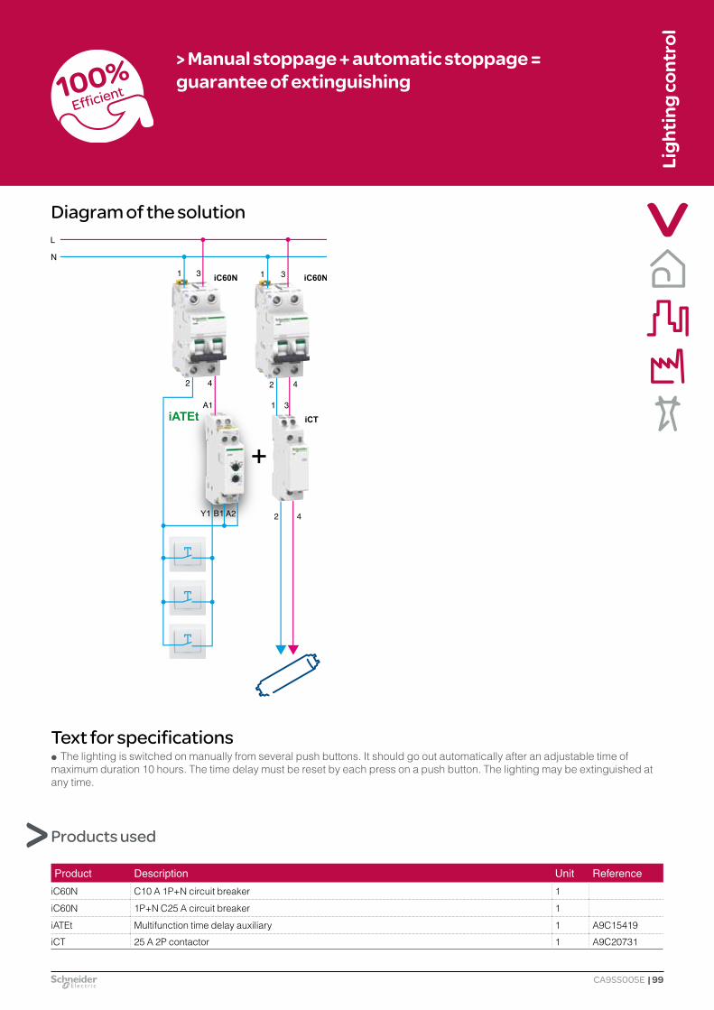
Ligh
ting
cont
rol
Diagram of the solution
| 99
Product Description Unit Reference
iC60N C10 A 1P+N circuit breaker 1
iC60N 1P+N C25 A circuit breaker 1
iATEt Multifunction time delay auxiliary 1 A9C15419
iCT 25 A 2P contactor 1 A9C20731
Text for specifications Q The lighting is switched on manually from several push buttons. It should go out automatically after an adjustable time of
maximum duration 10 hours. The time delay must be reset by each press on a push button. The lighting may be extinguished at any time.
> Manual stoppage + automatic stoppage = guarantee of extinguishing
Products used
iATEt
CA9SS005E

Zoom on
Lighting control
100 |
Lighting management in a stairway, a corridor or a lobby
Customer needs Q The building manager wants to achieve savings
on energy expenses related to lighting, while maintaining customer comfort.
Proposed solution Q The use of a MIN timer makes it possible to: O adjust the lighting period very finely, from one or
more control points, O automatically extinguish the lighting, O override the timer settings if permanent lighting
is needed. Q LED luminaires shall be preferred to compact
fluorescent lamps, to provide a longer service life and energy savings.
MINJust the light that is needed!
User/customer benefits Q Energy savings: automatic management of the lighting period makes it possible to precisely
optimize the light ON time. Q Easier operation: the maintenance personnel have access to permanent lighting by means of a
selector switch on the front of the timer or can restart the time delay by simply pressing one of the lighting push buttons.
Favorite applications:
Q hotels, Q residential
buildings, Q educational
institutions, Q etc.
MIN
ISC00879EN

Ligh
ting
cont
rol
Diagram of the solution
| 101
Product Description Unit Reference MIN Electromechanical timer 1 15363
iC60N C16 A 1P circuit breaker 1
> Programmed lighting period = energy savings
Text for specifications Q Be compatible with existing 3- or 4-conductor installations without altering the installation, via a selector on the product. Q Have an extinguishing time delay setting of between 1 and 7 minutes, without prior notice of lighting extinguishing, and be able
to override the installation's settings to permanent lighting. Q A press on a control push button restarts the preset time delay.
Products used
L
N
1
2
4
L
N
3
iC60N
MIN
4
L
N
3
MIM N
L
N
1
2
4
L
N
3
iC60N
MIN
4
L
N
3
MIM N
Connection to 3-conductor riser pipeConnection to 4-conductor riser pipe
ISC00879EN

Zoom on
Lighting control
102 |
Lighting management in a basement
MINt
MINtJust the light that is needed!
Customer needs Q The basement lighting must be able to be
controlled by several lighting points and extinguished automatically in case someone forgets.
Q This lighting must also be able to be extinguished by manual control.
Q The installation must be able to have a long time delay for maintenance and a permanent lighting function for works.
Proposed solution Q The use of a MINt timer makes it possible to: O set the lighting period to a minimum and have
prior notice of extinguishing, O extinguish the lighting by pressing one of the
push buttons (impulse relay function), O have two lighting override control modes:
- either permanent by actuation on the front of the device, - or for a period of one hour, by pressing one of the installation's push buttons for 2 seconds.
User/customer benefits Q Energy savings: automatic control of lighting extinguishing in case someone forgets can generate
significant savings. Q Flexibility: the integral impulse relay function allows manual extinguishing of the lighting by pressing
one of the installation's push buttons. Q Easier operation: two override control modes are available (permanent, long-term), making it
possible to cover the basement's various operating needs (cleaning, tidying, etc.).
Favorite applications:
Q housing, Q archive rooms, Q etc.
ISC00880EN

Ligh
ting
cont
rol
Diagram of the solution
| 103
LN
2
4
L
N
1
3
iC60N
MINt
Product Description Unit Reference
MINt Electronic timer with impulse relay function 1 CCT15234
iC60N C16 A 1P circuit breaker 1
Push button Wall-mounted luminous push button
> Manual stoppage + automatic stoppage = guarantee of extinguishing
Text for specifications Q Have an extinguishing time delay setting of between 0.5 and 20 minutes, with prior notice of lighting extinguishing, and be able
to override the installation's settings to permanent lighting. Q Extinguishing the lighting remains possible throughout the period of the time delay. Q Pressing a control push button for more than 2 s causes the start of a fixed time delay of one hour; a second long press allows
extinguishing.
Luminous push button
Products used
ISC00880EN

Zoom on
Lighting control
104 |
How to modernize the entrance of an apartment building
Customer needs Q Automatically limit the lighting period on an
existing installation equipped with a simple impulse relay.
Q Reduce the cost of lighting by preventing the lighting from being left constantly lit.
Q Notify the user of imminent extinguishing. Q Give remote access to a longer lighting time for
a removal or for maintenance work without adding extra controls.
MINp
Proposed solution Q The use of a MINp timer makes it possible to: O set the lighting period to a minimum in
corridors, stairs, the lobby, etc. using a timer to switch on one or more lamps from one or more control points,
O warn, through flickering of the lamps' light, that the lighting will soon be extinguished,
O have two lighting override control modes, either permanent by actuation on the front of the device, or for a period of one hour, by pressing one of the installation's push buttons for 2 seconds.
MINpJust the light that is needed!
User/customer benefits Q Energy savings: automatic management of the lighting period allows significant energy savings to
be achieved. Q User safety is improved by the function of switch-off warning of lighting extinguishing (the warning
consists of flickering of the lamps’ light). Q Ease of installation: the MINp is compatible with cabling of the 3- or 4-conductor type without
altering the installation. Q User comfort: two override control modes are available (permanent, long-term). They can cover the
various customary needs of the building entrance (cleaning, tidying, etc.).
Favorite applications:
Q hotels, Q residential
buildings, Q educational
institutions, Q etc.
ISC01577EN

Ligh
ting
cont
rol
Diagram of the solution
| 105
L
N
1
2
4
L
N
3
iC60N
MINp
Product Description Unit Reference MINp Electronic timer with switch-off warning 1 CCT15233
iC60N C16 A 1P circuit breaker 2
> Automatic stoppage + prior notice = guarantee of extinguishing + safety of movement
L
N
1
2
4
L
N
3
iC60N
MINp
Text for specifications Q Be fully compatible with existing 3- or 4-conductor installations without altering the installation. Q Have an extinguishing time delay setting of between 0.5 and 20 minutes, with prior notice of lighting extinguishing, and be able
to override the installation's settings to permanent lighting. Q Pressing a control push button for more than 2 s causes the start of a fixed time delay of one hour; a second long press allows
extinguishing.
Products used
Connection to 3-conductor riser pipeConnection to 4-conductor riser pipe
4-wire riser pipe 3-wire riser pipe
ISC01577EN

Zoom on
Lighting control
106 |
Optimizing the lighting of open office spaces
Customer needs Q On average, over one-third of the total energy
consumed in office buildings is used for lighting. Q In this type of building, occupied mainly during
the daytime, undeniable energy savings can be achieved by optimizing luminaire lighting times.
Q This installation can manage extinguishing of the lighting at the desired times, while allowing users to control the luminaires outside of the programmed period.
User/customer benefits Q Energy efficiency: optimization of lighting times allows energy savings of up to 30%. Q Simplicity: O automated and secure lighting management solution, O indications on the front of the product. Q Safety: padlocking possible without any additional accessory. Q Continuity of service: the Reflex iC60 is a bistable actuator which does not change state in the
event of a power outage.
Favorite applications:
Q offices, Q educational
institutions, Q industry, Q retail trade, Q etc.
Proposed solution Q Lighting circuits are switched on and off by
office users by means of ambience control push buttons located in each zone.
Q An IHP time switch sends to the Reflex iC60 protection and control devices orders for extinguishing according to the building's operating requirements.
Q The Reflex integrated-control circuit breakers are configured in mode 1 to allow local restarting of the lighting.
Reflex iC60
Reflex iC60Integrated-control circuit breaker!
CA9SS030E

Ligh
ting
cont
rol
Diagram of the solution
| 107
> Automatic stoppage + local control = guarantee of extinguishing + user comfort
Products used
Text for specifications Q The lighting loads must be powered via an integrated-control circuit breaker. Q Lighting circuits are switched on and off by the users of the premises by means of ambience control push buttons. Q Centrally controlled extinguishing of lighting circuits must be able to be programmed by means of a time switch. Q It must be possible for the occupants to restart the lighting outside of the programmed lighting times.
Product Description Unit Reference
iC60N C10 A 1P+N circuit breaker 1 -
Reflex iC60N 25 A C-curve 2P integrated-control circuit breaker 2 A9C52225
IHP Weekly programmable time switch 1 15854
LN
L1 3
2 4 2
2Y2Y1 11 14PN 4 2PN 4
1
NIHPiC60N
1 3 1 3Reflex iC60 Reflex iC60
Y2Y1 11 14
Office 1 lighting
Mode 1
Office 2 lighting
Mode 1
CA9SS030E

Zoom on
Lighting control
108 |
Management of a large office building
Customer needs Q Automate the lighting of a large office building,
while retaining the possibility of local control. Q Manage energy consumption, and luminaire
maintenance. Q Adapt the lighting according to: O a timer program, O the presence of people, O the level of natural light based on several areas. Q Perform override control of lighting by area. Q Rapidly reallocate a work area.
User/customer benefits Q Fast installation: Canalis busbar trunking, formed of prefabricated elements, can be installed
rapidly and safely. Connections require no tools and are designed to prevent any risk of incorrect connection.
Q Reallocation of the various offices. Q Simplified maintenance: no preventive maintenance campaign (renewal of the lamps according to
their service life). Q Simple lighting management and cost saving scenarios.
Favorite applications:
Q offices, Q educational
institutions, Q etc.
Proposed solution Q The choice made is a KNX type Building
Management System, connected to a "Canalis KBB" busbar trunking architecture, DALI-compatible, performing the functions of lighting management, measuring and monitoring.
Q The use of DALI detectors located in each area makes it possible to maintain a constant luminosity level in the presence of employees, for optimal working conditions.
Q Override setting of the lighting for each area is performed by KNX switches.
Q Fault information is sent by the ballasts via the DALI communication network.
Q By rearrangement, it is easy to allocate new monitoring points for an office or group luminaires.
KBB Rigid busbar trunking!
Canalis KBB
CA9SS035E

Ligh
ting
cont
rol
Diagram of the solution
| 109
Canalis KBB
DALI
KNX
Argus Argus Argus
KNX
L N L N
InterfaceKNX/DALI
Power supplyD+ D -ALI
L N
KNX/DALID D
Ca
L N
Power supply
Product Description Unit Reference
Canalis KBB 40 A straight element (with communication bus) KBB40ED4303TWCanalis KBB 40 A power supply box 1 KBB40ABG4TWCanalis busbar trunking Fasteners KBA40ZFUWCanalis busbar trunking Tap-off connectors KBC16DCB21+KBC16ZT1KNX KNX local switch 1KNX KNX power supplyKNX DALI/KNX gatewayArgus Argus presence detector 3iC60N 1P+N C6 A circuit breaker 1iC60N 3P+N C40 A circuit breaker 1
> Pre-cabling + communication network = easy reallocation + control of energy consumption
Products used
Text for specifications Q The lighting management system used consists of a decentralized distribution system incorporating a DALI communication
bus connected to a Building Management System. It performs control of the luminaires by area, and allows the creation of lighting scenarios according to the occupants' hours of presence and the extinguishing of unoccupied areas.
Q Formed of prefabricated elements with tap-offs, it offers great flexibility of installation and is completely scalable. Q Connections require no tools and can prevent any risk of a connection error.
From 1 to 6 luminaires
Electronic ballast
CA9SS035E

Zoom on
Lighting control
110 | CA9SS031E
Automating the lighting for an industrial workshop
Favorite applications:
Q industrial workshop,
Q conference room, Q station platform, Q airport hall, Q supermarket, Q etc.
Customer needs Q The lighting of an industrial workshop is of
prime importance to ensure employee safety and good productivity at work stations.
Q To optimize consumption, it is advantageous to automate luminaire lighting times according to work periods.
Q For safety reasons, employees must not be able to switch off the luminaires. However, it is necessary to allow local override control for performing maintenance operations (change of lamps or night work in the workshop, for example).
Q This installation allows the operator to choose an automated or manual mode for the control of each lighting circuit.
Proposed solution Q The lighting loads are powered by an
integrated-control Reflex iC60 protective device. Q The Building Management System (BMS)
sends to the Reflex switch-on and switch-off orders according to the building's operating requirements.
Q The Reflex integrated-control circuit breaker is configured in mode 3 in order to allow override setting of the lighting to ON or OFF to be performed by the operator.
Q The light switch-on/switch-off data and electrical faults are transmitted to the facility's supervision room.
User/customer benefits Q Simplicity: no LV power interface between the Reflex and the Building Management System (BMS),
lower cabling costs, up to 50% fewer connections, indications on the front of the product and remote indications.
Q Flexibility: possibility of manual override control. Q Safety: padlocking possible without any additional accessory. Q Continuity of service: the Reflex iC60 is a bistable actuator which does not change state in the
event of a power outage.
Reflex iC60Integrated-control circuit breaker!
Reflex iC60N with Ti24 interface

Ligh
ting
cont
rol
Diagram of the solution
| 111 CA9SS031E
Text for specifications Q The lighting loads must be powered via an integrated-control circuit breaker. Q ON/OFF control of lighting circuits must be supervised by a management PLC connected to a BMS. Q Manual override setting of the lighting to ON or OFF can be performed by a selector switch on the front of the electrical
distribution switchboards. Q The light switch-on/switch-off data and electrical faults are transmitted to the supervision system, without any additional LV
power interfaces.
Products used
2 4 6 8 2 4 6 82 4 6 82 4 6 8
L1L1L1
1 3
2 4
iC60N
N
L + -N
SD
Y3SD
OF0+24V
+24V
0 V
Y3
OF SDY3 OF
1 3 5 7 1 3 5 7
N NP P Y1Y1 Y2Y2
Y3SD
OF0+24V
Reflex iC60
Reflex iC60
ON/OFF/Auto
Mode 3 Mode 3
ABL8 power supply230 V AC/24 V DC
TwidoRemote management + local automatic control from a lighting system
Management interface Supervisor, BMS, GTB
TACRemote management from an HVAC system
Advantys OTBRemote management from a lighting system
Selector switches, 3-position
ON/OFF/Auto
> Remote management + manual control = continuity of service + savings
Product Description Unit Reference
iC60N C10 A 1P+N circuit breaker 1 -
Reflex iC60N C25 A 4P integrated-control circuit breaker with Ti24 interface (mode 3 setting) 2 A9C62425
Harmony K series 3-position selector switch, dia. 22 mm 2 -

Zoom on
Lighting control
112 | CA9SS037E
Lighting for a humid room
Customer needs Q Be able to control lighting in a humid room,
while ensuring personnel safety, taking into account sanitary requirements and the floor and wall cleaning operations performed each day.
User/customer benefits Q Ease of installation: the control terminal connection capacity allows the use of cable of cross
section up to 4 mm2. Q Safety: the 4 kV isolation level between the coil and the power contacts can meet the requirements
of a Safety Extra Low Voltage (SELV) installation.
Favorite applications:
Q educational institutions,
Q hotels, Q industry, Q infrastructure, Q etc.
Proposed solution Q The iTL impulse relay with 24 V coil, together
with a power supply via iTR safety transformer, ensures a level of isolation between the mains voltage and the control voltage.
Q All guarantees must be taken (sealed push button, use of SELV, earth leakage protection) to ensure personnel safety and protect it from electrical hazards.
iTLThe impulse relay!
iTL

Ligh
ting
cont
rol
Diagram of the solution
| 113 CA9SS037E
> Safety Extra Low Voltage + impulse remote control = personnel protection
Products used
Text for specifications Q The impulse relay must have a performance level in compliance with the regulatory requirements for a "Safety Extra Low
Voltage" (SELV) electrical installation.
iC60N + Vigi
iTR iTL24 V AC coil
230 V AC
24 V AC
Humid room
Sealed PB
IP65
Product Description Unit Reference
iC60N C2 A 1P+N circuit breaker 1
iC60N + Vigi iC60 C16 A 1P+N circuit breaker + 30 mA Vigi earth leakage protection module 1
iTL 16 A, 24 V AC 2P impulse relay 1 A9C30112
iTR 16 VA, 12-24 V AC safety transformer 1 A9C15918

Zoom on
Lighting control
114 | LSB02301EN
Emergency lighting in a public building: junior high school
Customer needs Q Produce an emergency lighting installation in
compliance with the regulations allowing signage and ambient lighting to reach the emergency exits in case of evacuation of the institution during a power cut.
Q The equipment installed must be unremovable with conventional tools, and that installed in cloakrooms and sports rooms shall be reinforced to prevent damage.
Q The self-contained emergency lighting units ("BAES") installed shall be able to indicate their operating condition.
Q In the event of a deliberate power cut, the units must be idled to prevent them from discharging.
Proposed solution Q The use of anti-panic emergency lighting units
and signage can: O reduce the risk of panic, O make evacuation paths and obstacles visible. Q The range has accessories: tamper-proof
screws and wire guards. Q They are "self-testable" and perform regular
checks on their operating condition. Q The TBS 50 remote control prevents the
batteries from discharging in the event of a deliberate mains power cut.
User/customer benefits Q Easy, fast installation: the emergency lighting units are designed to simplify the work of the
installer: numerous handling operations are performed without tools. Numerous mounting possibilities. Simplified markings, quick connectors, cable glands, accessories.
Q Lower maintenance costs: provided with integral self-control, they make regular checks on the light source, the battery and the electronic module. The results are indicated by multicolored LEDs.
Q Extended service life: the LED technology reduces power consumption and increases the degree of reliability and service life of the installation.
Favorite applications:
Q offices and educational institutions,
Q hotels, Q industry, Q retail trade, Q infrastructure, Q etc.
BAESEmergency lighting unit!
Evacuation BAES Anti-panic/ambient BAES

Ligh
ting
cont
rol
Diagram of the solution
| 115 LSB02301EN
Text for specifications Q The installation shall be executed with self-testable anti-panic emergency lighting and ambient lighting units. Q The installation shall be stopped in the event of a deliberate power supply cutoff.
Products used
–+
+
+ –
TBS 50 iTL16 A
iTL16 A
– + – + –+ –
iDPN10 A
iDPN16 A
iDPN16 A
iDPN16 A
1L N
N 2
N 1 N 1
N 2
N 1
N 2
N 1
N 2
3
2 4 4
1
A1 A1
A2 A2
3
2
> Good marks for purchasing and maintenance costs:> The combined cost of purchase and maintenance of the LED versions is far less expensive than the purchase and maintenance of fluorescent tube units (no change of fluorescent tubes).
Product Description Unit Reference
iDPN C16 A 1P+N circuit breaker 3
iDPN C10 A 1P+N circuit breaker 1
TBS 50 Remote control for emergency units (max. 50 units) 1
iTL 16 A impulse relay 1 A9C30812
BAES Evacuation unit 1 or more
BAES Anti-panic/ambient lighting unit 1 or more

01-2015A9 GT 15 E C
Schneider Electric Industries SAS
© 2
015
Sch
neid
er E
lect
ric In
dust
ries
SA
S -
All
right
s re
serv
ed
As standards, specifications and designs change from time to time, please ask for confirmationof the information given in this publication.
Publishing: Schneider ElectricDesign - Layout: SEDOCPrinting:
Printed on ecological paper
35, rue Joseph MonierCS 3032392506 Rueil Malmaison Cedex France
RCS Nanterre 954 503 439Capital social 896 313 776 €www.schneider-electric.com
Make the most of your energySM
www.schneider-electric.com