level9 d ddc - defense technical information center · s• small arms ammunition to assure their...
TRANSCRIPT
D DDCLEVEL9US ARMY TEST AND EVALUATION COMMAND JUL 1I 1978
TEST OPERATIONS PROCEDURES
, DRSTE-RP-702-103/STest Operations Procedure 4-2-011'
AD No.
Parara hPage
_ Section I. GENERALPurpose and Scope ........... .... 1 1Background ... ............ ... 2 1Equipment and Facilities ... ..... 3 2
" II. TEST PROCEDURESSupporting Tests ...... . . . 4 2
III. SUPPLEMENTARY INSTRUCTIONSTest Planning ....... ...... ..... •.5 4.
(The paragraphs containing instruc- , F'Ctions for soecific subttasts are ______
listed in paragraph 4.)
ftC, APPENDIX. REFERENCES .... ......... ..
C.5J, =SECTION I
LL.. GENERALJ
,m •m 1. Purpose and Scope. This TOP provides guidance for planning tests ofS• small arms ammunition to assure their conformance with MN's, DP's, and
', • other standards. Tests to satisfy the requirements for the particulartest item and test type (i.e., development test, initial productiontest, etc.) can be selected from those listed in section II.
2. Background. The term "small arms ammunition" for this TOP is defined
as a tixed round of ammunition, varying in size from caliber .22 (orsmaller) to 30-mm, but including the shoulder-fired 40-mm, grenade. Theammunition is divided into three specific categories:
a. Fuzed and nonfuzed service ammunition, both combat and noncombattype such as caliber .22 rimfire, riot control, and disintegrating ammuni-tion.
b. Blank ammunition.
c. Dummy or training ammunition.
The testing of 40-mm grenades is not discusseh ig,,this •Pincetests are covered in TOP 4-2-080. L U K) ý • 4
Avoroed fJo a 715
TOP 4-2-016 12 June 1978
3. Equipment and Facilities. With the exception of Mann-type barrels,equipment and facilities requirements for the tests in this TOP are in-dicated either in section III or in the publications referenced insection II.
The Mann-type barrel is a single-shot mechanism used to determinecharacteristics inherent in the ammunition exclusive of the serviceweapon. The wall thickness of the barrel is normally 1 inch greater
than that of the standard weapon barrel, making it very heavy andmassive. The internal dimensions are highly accurate. Firing with aMann-type barrel is usually conducted from .a fixed mount.
SECTION IITEST PROCEDURES
4. Supporting Tests. Subtests to be considered in formulating a testplan, with applicable TOP/MTP and other references, are listed below.The tests are listed in a preferred order of completion with respect tohigh risk. The methods are written in a manner to be inclusive forvarious designs. For specific applications and cartridge designs it may,however, be necessary to incorporate additional tests, modify some ofthe methods outlined, or develop new methods.
TEST SUBJECT TITLE PUBLICATION NO.
Fuzed and Nonfuzed Service Ammunition
NOTE: 'Te (F) following the test ticle indicates that the test is appli-cable only to fuzed rounds.
a. Initjal Inspection (refe to para 6) MIL-STD-636
b. Physical Measurementa (para 7) TOP/MTP 4-2-800
c. Safety Evaluation (para 8):
Velocity Measurements (pars 9) TOP/MTP 4-2-805
Pressure Measurements (para 10) TOP/ATP 3-2-810
Action Time (para 11) 11)i
"Fuze Arming Distance (F) (para 12)
Muzzle Impact Safety (F) (para 13) . .A-.,
Out-of-Line Detonator (F) (para 14) MIL-STD-331
Self-Destruct (F) (para 15) .
2 .
12 June 1978 TOP 4-2-016
TEST SUBJECT TITLE PUBLICATION NO.
Cook-Off (para 16) TOP/MTP 3-2-045, 3-2-059
Functioning and Casualty/MetalParts Inteirity (para 17)
Fuze Sensitivity (F) (pars 18)
Rough Handling (pare 19) TOP/MKP 4-2-602
Secured Cargo (Transportation TOP 1-2-601Vibration) (parý 20)
Projectile Torque (pare 21)
Bullet Pull (par& 22)
Noise and Blast (para 23) TO',w 1-2-608
Impulse-Recoil Measurements TF-,P 3-2-826(pars 24)
Weapon Compatibility (para 25) '.0P/MTP 3-2-045, 3-2-059
d. Fragmentatlon-Lethality (F) (para 26) TOP/MTP 3-2-608, 4-2-813
a. Accuracy and Dispersion (para 27) TOP 4-2-829,TOP/MTP 3-2-045, 3-2-059
f. Time of Flight (.ange Tables) TOP/MTP 4-2-604, 4-2-827
(para 28)
g. Tracer Evaluation (pars 29)
h. Flash (par& 30) TOP/tTP 3-2-045, 3-2-059
i. Smoke (pars 31) TOP/MTP 3-2-045, 3 - 2-05q
J. Waterproofness (para 32) MIL-STD-?Il
k. Salt-Fog (pare 33) MIL-STD-310C
1. Tempersture-Humidity (para 34) TOP/MTP 4-2-820, AR 70-38
m. Sympathetic Detonation k'para 35) MIL-STD-444
n. Armor Penetration (para 36) TOP 2-2-710
o. Helmet Penetration (par* 37) TOP 2-2-710
3
TOP 4-2-016 12 June 1978
TEST SUBJECT TITLE PUBLICATION NO.
p. Fungus (par& 38) MIL-STD-810C
q. Human Factors Engineering (para 39) TOP 1-2-610, IIIL-STD-1474
lank. Amunition (para 40)
r. Function and Casualty (para 40.1)
a. Weapon Compatibility (par& 40.2) TOP/MTP 3-2-045, 3-2-059
t. Noise Level (para 40.3) TOP 1-2-608
S.1. Flash and Smoke (para 40.4) TOP/MTP 3-2-045, 3-2-059
v. Tampering (para 40.5)
SDummy or Training Ammunition (para 41)
w. Inspection (para 41.1)
x. Physical Measurements (para 41.2)
y. Serviceable Life (para 41.3)
SECTION III
SUPPLEMENTARY INSTRUCTIONS
NOTE: Paragraphs 5 through 39 are applicable to service ammunition.
5. Test Planning. DT 11 planning requires a comprehensive test programfor which the test director must be thoroughly familiar with the statedrequirements (MN, DP, etc.). All inscrkictional material issued with thetant amunition by the manufacturer, contractor, or government, as wellas reports of previous tests conducted on the same model or closely re-lated items, 4re reviewed and kept available for reference. The developer'ssafety statement is reviewed and used for integrating safety into thetest design, for planning, for preparing the tear procedures, and forhandling and shipping the test items prior to the issuance of the safecyrelease.
An adequate number oi test cartridges ij required to represent thepopulation from which the sample has seen drawn. If the sample is toosmall to produce adequate or statistically significant results, a de-
, cision relative to acceptability may not be made with confiJence.Although economy of test is also considered, the sample size uf each sub-test must be sufficient to provide reasonable assurance that comparisonof test reaults to requirements will be meaningful.
S-4
12 June 197? TOP 4-2-016
Test results are analyzed "Vy aut.table stat'stical procedures forcomparing samples, for obtaining point and interval estimates of aparameter of interest, and for determining from test results whetherspecified requirements have been satisfied. TOP/MTP 3-1-002, ConfidenceIntervals and Sample Size, provides guidance on analysis and presentaLionof test results.
6. Initial Inspection. All cartridges received for testing are in-spected for damage and defects (external). Inspection standards forsmall arms ammunition through caliber .50 are contained in MIL-STD-636.(APG personnel should refer to SOP 385-292, Inspection Procedures forAll Ammunition and Related Items Subjected to Testing.) All ammunitionconsidered questionable or unserviceable due to shipping damage will b,1restricted from the test.
7. Phycical Measurements. Since it is not feasible to check all mea-surements of a complete round of ammunition (particularly if it is afuzed HE round), engineering judgment must be used to select criticalareas for check. These, as a minimum, should include (methods are asshown in TOP/MTP 4-2-800):
a. Complete cartride.i
(1) Weight.
(2) Center of gravity.
(3) Length.
(4) Profile.
(5) Projectile diameter at bourrelet (or. rotating band oflarger caliber amaunition).
l bg Componentr (cartridge must be disassembled)
(1) Bullet: weight, length, and moments of inertia.
(2) Propellant: weight, •ype, and general appearance.
Fuoed aoumun tiot reqtires a sample with ceitified-inert componentsfor examination to determine whether the safety features prescribed by
the drawing are present. Critical components (based on engineeringj•udgment) are compared with drawings. Sampling from the rounds furnished
. or, a random basis and must be sufficient to provide, as a minimum,statements at the lower 90 percent confidence limit esee TOP/MTP 3-1-002).A complete set of cartridge and component drawings is required prior totest initiation, and the requirement should be noted in the plan of test.
5
I TOP 4-2-016 12 June 1978
It 8, Saftty Evaluation. Whan a complete DT 11 type test of small4mi. . mmuntion is to be conducted prior to a man-machirna &,;aluao..
,h-_-'- and an operational test (OT), the information necessary for thepreparation of a safety release recommendation in usually generated fr',ruthe cumulative results of various subtests. When the man-machinc cval-uation and the OT tests are to be conducted concurrently with a DT I1test, however, a separate safety evaluation test must be conducted assoon as possible following initial inspection, and the results reportedin latter form to the appropriate TECOM directorate. A safety recommenda-tion reflects engineering judgment based on a careful study of all features,particularly those relating to hazardous conditions or unsafe design.Any or all of the subteots in this TOP, but particularly those listedin paragraphs 9 through 25, should be considered as part of a safetyevaluation. In general, however, preliminary safety recommendations canbe made for a given design based on a limited number of rounds firedunder given conditions.
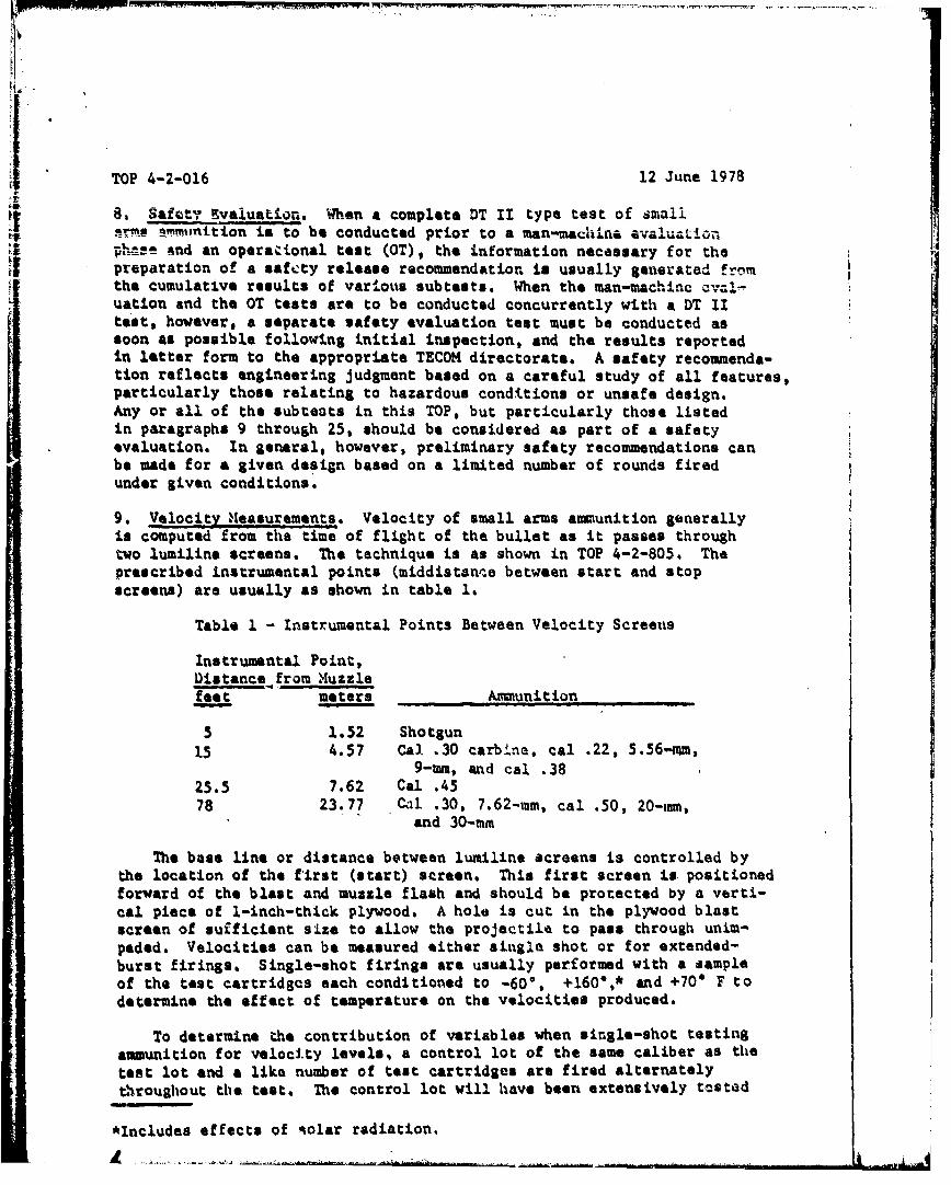
9. Veloc!itX beasurements. AA Velocity of small arms ammunition generallyis computed from the time of flight of the bullet as it passes throughtwo lumiline screens. The technique is as shown in TOP 4-2-805. Theprescribed instrumental points (middistanqe between start and stopscreens) are usually as shown in table 1.
Table 1 - Instrumental Points Between Velocity Screeus
Instrumental Point,Distance from Muzzlefeet meters Ammunition
5 1.52 Shotgun15 4.57 Cal .30 carbina, cal .22, 5.56-mm,
9-mn, and cal .3825.5 7.62 Cal .45
78 23.77 Cal .30, 7.6 2 -mm, cal .50, 20-mm,and 30-mm
The base line or distance between lumiline screens is controlled bythe location of the first (start) screen. This first screen is positionedforward of the blast and muzzle flash and should be protected by a verti-cal piece of 1-inch-thick plywood. A hole is cut in the plywood blastscreen of suificient size to allow the projectile to pass through unim-peded. Velocities can be measured either single shot or for extended-burst firings. Single-shot firings are usually performed with a sampleof the test cartridges each conditioned to -600, +160*,* and +70* F todetermine the effect of temperature on the velocities produced*
To determine the contribution of variables when single-shot testingammunition for velocity levels, a control lot of the same caliber as thetest lot and a like number of test cartridges are fired alternatelythroughout the test. The control lot will have been extensively tested
*Includes effects of solar radiation.
71i
12 June 1978 TOP 4-2-016
to establish the velocity (also pressure) under conditions of +70' F ina series of Mann-type barrels (para 3). The control ammunition is alwaysfired after being conditioned ;o +70' F, and the amount that the testedvelocity misses the assessed value is added algebraically to the testcartridge velocity. Values are reported as corrected velocity alongwith tho 'as tested" (uncorrected) velocity. The rate of fire duringthe test should not exceed one round per half-minute interval, and thebarrel should be cooled to ambient temperature following each sequenceof firing.
10. Pressure Measurements, Pressure measurements for small arms ammuni-tion can be taken at two stations: chamber, for all ammunition, andport for all ammunition fired from a gas-operated weapon; the latter isusually measured simultaneously with chamber pressures and at thelocation of the gas port of the intended weapon.
Mann-type barrels with pressure stations (chamber and port) are usedto conduct the pressure measurement test. The barrels must conform tothe basic weapon in length, rifling, chambering, and position of thegas port. Copper crusher gages can be used to measure peak pressuresat both stations. Time-pressure histories can be recorded using piezo-electric pressure transducers rather than copper crusher gages. Thetechniques for the use of both the crusher type and the piezoelectrictransducer are described in TOP/HTP 3-2-810. Velocities should bemeasured during this phase for informational purposes. Firings are con-ducted with samples of the test ammunition conditioned to -60', +160" *,and +70* F to determine the effects of temperatures on the resultingpressures. Control ammunition is fired alternately along with the testammunitior, and the pressures are corrected similarly to the methoddescribed for velocity corrections (9 above).
11. Action Time. The purpose of the action time test is to determinethe time interval between the application of initiating energy to theprimer and exit of the projectile from the muzzle. This information isuseful for determining ammunition compatibility with weapons that arecapable of high rates of fire or are externally powered. In the caseof high-rate-of-fire weapons, the bolt must be locked in position untilthe projectile leaves the bore to maintain propellant pressures. Forthe externally powered weapon (i.s., not gas operated) the possibilityexists that bolt unlocking can occur either when the projectile is inthe bore or prior to ignit.ion of the propellant (in cases of extremelylong action-times generally referred to as "hangfires") and result inpossible ejection of a cartridge in the process of ignition.
Firings are conducted single shot from a Mann-type barrel using an
instrumented breech to obtain initiation and an infrared detector co de-
termine projectile exit from the bore. A counter chronograph is used
to indicate the time from initiation to projectile exit. An infrareddetector will not \,ecord reliably with some projectiles due to discarding
*Includes effects of solar radiation.
TOP 4-2-016 12 June 1973
sabots, gas escapage, etc. In these instancus, lumiline screens areplaced in front -it the \toapon muzzle to determine when the projectilepasses a given point (chronograph stop time) and to provide data forcalculating the velocity of the projectile, The time for each proje.c-tile to travel .rom the muzzle to the first screen is computed usingpreviously obtrined ballistic data and the recorded velocity observedfor each round. This time is subtracted from the total time observedto obtain the action time. Firings Are conducted with the ammunitionconditioned at -604, +160*,*, and +700 F to determine temperature affects.
12. Fuze Ar".dng Distances, Fused HE avmunition must be safe (i.e., notarmed) for a prescribed distance forward of the weapon muzzle. Thisassures that inadvertent "close in" impacts will not cause the fuze tofunction and expel fragments in close proximity to the weapon. Minimum(none armed) and maximum (all armed) arming distance requirements are"established in the appiopriate requirements documents. These distancesare verified by firing a statistically adenuate sample of the test car-tridges single shot from the service weapon to impact on a verticalfunctioning target. This target is placed initially at the minimum pre-scribed distance, then the firing test is repeated at the maximumdistance. Firing of 45 rounds at each distance is often prescribed. Iino arming occurs at the minimum distance, it may ue said that there isa probability of .95, with 90 percent confidence, that !Amu fuze will notbe armed at that distance. Forty-five Prmings at tht. maximum distancewould give the same probability of arming. Other amplo sizes willprovide other probabilities as stated in TOP/MTP 3-1-002. The functioniagtarget material is thick enough to cause the fuze to fvuction reliably(see plate sensitivity, par& !8b), but not so thick ,& to cause deflagra-tion of the explosive filler in the projectile. If a Iate sensitivitytest has not been conductAd or no guidance on sensitivity is providedin the requirements document, a 0.040-inch-thick aluminum plate is usedfor a functioning target.
If the arming distances stated in the requirements document are rtotmet or no parameters on the minimum and maximum distances are provided,they may be established using one or both of the following procedures.
a. When the number of available rounds is small, or for obtainingpreliminary information, the Langlie method is suitable. This procedurerequires that the gun-to-target distance be adjusted round by round basedon an analysis of the results of preceding rounds fired. For the Lzt)liemethod:
(1) An upper limit of distance and a lower limit of distance areselected: the upper limit beiag a distance at which it would be expectedthat all fuzes would be armed, the lower limit one at which no fuze wouldbe armed. (It is better to select this interval too large than too small.)
(2) The target is placed at a diotance midway between the upper
and lower limits, and the first round is fired.
*Includes effects of solar radiation.
. -.... .t
12 June 1978 TOP 4-2-,A6
(3) If the first round functions, the target for the secondround is placed halfway betwren the diatance for the first ro%%nd and thelower limit. If the first round does not function, the target distancefor the second round is halfway between the distance for the first roundand the upper limit.
(4) If the first tvo rounds result in a reversal (one functionand one nonfunction), the distance for the third round is halfway betweenthe distances for the first and second rounds. If the first two roundsfunction, the distance for the third round is halfway between the second-round distance and the lower limit. If the first two rounds producenonfunctions, the distance for the third round is halfway between Lhesscong-round distance the the upper limit.
(5) If the first three rounds fired in the sequence produce allfunctions or all nonfunctions, selection of new limits is advisable andthe sequnce started anew.
(6) Succeeding rounds ara fired using the following rules:
If the preceding pair of rounds resulted in a reversal,the next-round distance is halfway between the distance for the tworounds of the pair.
If the preceding pair of rounds did not produce a rwversal,the last four rounds 4re examined. If the number of functions anduonfunctions is equal, the next-round distance is halfway between thedistances for the first and last round of that group. If the lastfour rounds did not have an equal number of functions and nonfumctions,the last six, eight, etc., are examined, until the nimber of functionsand nonfunctions is equal. The distance used is always halfway betweenthe distancos for the first and Last round of the group examined.
If the above conditions cannot be satisfied and the lastround resulted in a function, the distance for the next rour.d is halfwaybetween the distance for the last round an~d the lcuer limit; otherwise(last round was a nonfunctioa), halfway between zhe distance for thelast round and the upper limit.
The above procedure is follomed until the rounds allocatedare expended.
(7) The data are plotted and the maximum likelihood estimatesof the man and standard deviation for the arming distance are calculated.
b. When a large number of rounds are available, a more efficientmethod of determining arming distance (the target is moved after a groupof rounds is fired rather than after each ro%mri) is as follows:
(1) Based on engineering judgment and experience from the testingof simil.ar Itemsr,-a point halfway between the estimated minimum and maxim~m
9
TOP 4-2-016 12 June 1978
arming distance is selected. A functioning target is located at this pointand a 10-round sample size fired. Based on the results of this firing thefumctioning target is moved to bracket the distances. The procedure isrepeated until the minimum, maxivaum, and 50-percent arming distances havebeen located.
(2) The data are used for calculation of maximum likelihoodestimates of the mean and standard deviation of arming distance, as viththe Langlie method above.
Additional firings may be conducted with amnmunition conditioned tohigh and low temperatures to determine the effect on the arming andnonarming distances established at ambient range temperature.
13. 'Mzzle Impact Safety. This test is conducted to verify that thesafety devices of the fuze are so arranged that they will prevent detona-tion of the fuze-projectile combination at any impact shore of the mini-mum prescribed distance. This test is usually conducted following thefuze arming test (12 above). A functioning target of the same thicknessas used in the fuze arming test is placed &a close in front of the muzzleas feasible. A series of single-shot firings are conducted to determinewhether the fuzo functions when it strikes the target. The successfulcompletion of this test (no functions) usually implies similar safetyof the fuzed round while in the bore of the woaponý
14. Out-of-Line Detonator. There is a requirement for fuzed cartridgesthat the fuze not be armed while in the born of the weapon. This is ac-complished by creating an interruption in the explosive chain in thefuse mechanism. 'this interruptive mechanism can be in the form of aslider that is spun outward by centrifugal force as the projectilespins during flight, allowing uninterrupted movement of the firing pinon projectile impact, or, as in many fuzes, a ball rotor containing adetonator held out of line during barrel travel. Regardless oi themethod used to interrupt the fuze firing chain, there must be a test todetermine the extent of hazard should an explosive element function inthe "out-of-line" position.
The basic procedures for this test are described in test 115 of jjHIL-STD-331. The test consists of firing one or more explosive componentsin sample fuzes, checking the effectiveness of the explosive train in-terrupter, and determining whether or not there is ejection of parts, de-formation, or shattering that might result in unsafe conditions. Thereis no set of standard equipment for this test because the fixtures mustbe designed to hold in place the parts of the particular fuze being t Al-uated. Modificý.tion to the test fuze is usually necessary. In the .45soof a percussion-fired fuze, a hole might be drilled through the side ofthe fuze and a special firing pin inserted for initiating the sensitiveexplosives in their unarmed position. With an electrically initiatedfuze, special holes may have to be drilled to insert an initiator forthe detonator. For all types of fuzed projectiles, the test, startingwith a fuze in the unarmed position, is conducted as a systematic LIvesti-gation of the effects of firing sequentiallý or simultaneously all ex-10
r,
12 June 1978 TOP 4,2- -- 16
plosive components of the explosive train, The o0rder (n.1 manner, orfiring should be designed to axpose any possibility of dafeatini,, thepurpose of the fuze interrupt~er.
15. Self-Destruct, When HE annunition ". employed ii. the air defenserole, firings may be condu,..ted in the directi.on of fri.fLirly tr;op!, orinstallations. It is desirable, therefore, t:hac faiiu.:Els to hit theaircraft not result in live HE anmunitLicn impacting :,r functL. ning infriendly areas. Ammunition designated for thi. role vust always containa mechanism (mechanical or pyrotechnic) to initiate tL'ie projectile aftei:a preset time of uninterrupted flight. The purpose o.'f this test is toverify that the ammunition possesses such a mechani',ii and th;At it functionswithin the prescribed time delay.
This test is usually accomplished by firing the ammunition sirgleshot and determiniin the time from firing to self-de*truct. The elapsedtime is recorded using an initiator, usually a recoil-operated switch,to start a chronograph and an infrared detector to stop the timing actionwith the occurrence of an airburst function. Firing elevations must besuch that the minimum and maxdmum permissible times are at least withinthe field of the infrared detector. A second method thit can be used,if an infrared detector is not available, is to tme the interval fromfiring to self-destruct manually with stopwatches. Doppler velocimmtersmay be required to obtain self-destruct timels if the visual and infraredsignatures are bmall. If required, the range to self-destruct can becalculated by use of the data established in the time-of-flight testdescribed in paragraph 27.
16. Cook-Off. The purpose of this test is to determine the minimum numberof rounds that can be fired before the chamber of the weapon becomes suffi-ciently heated to cause the round to fire from heat condition. Within thesmall arms area, both cartridges with HE fuzed projectiles and cartridgeswith inert nonfuzed projectiles b tve to be considered. The cook-off testingof nonfuzed ammunition is described in TOP/MTP 3-2-045, Machine Guns andAutomatic Weapons, and TOP/MrP 3-2-059, Hand and Shoulder Weapons.
Fuzed, HE-loaded ammunition presents another problem in that, inaddition to the primer-propellant possibility of cook-off, there existsin the complete cartridge the following components that can be ignitedby conductive heating:
HE-filled projectile.
Fume with, normally, an explosive detonator and booster.
It is of prime importance to develop the c)ok-off characteristics ofeach explosive component relative to the other, so that the significanceof the explosive event may be determined. The firing of the primer orpropellant under these conditions generally causes uncontrollable firing
*. of the weapon, which under some circumstances would be critical. Theignition of the fuze or shell body components (pri.or to the ignition of
L 11-. ,. -
TOP 4-2-016 1.2 Juno 1.9 .,
the primer or prc.psllant) poses a serious problem in that the wc~a',po', s.)..L
most certaiiiy bix deimaged an6 pervsonnel close to tho weapon may be .a..Jured. £mphasis should therefore be diroctfid to fu;e:.-projI.bctile c,;',,ponents re.'.ativE: to the cook-off leva.l of the primeaw-propeLl.art. '1'16 1scan be ac.cmpli heeL in two ways.,
a. S.,atir. test. The individaal covmponant iYs subjected to i,',, .,temperatu,:es a',d the level at ignition racorded. Compoini.. shcv'uii 7..assembled intc a t:omplete cartridge with ,l components inert exrttp,: tileone under tnv..stI.Sation; e.g., live detonator, i'-ert booster, in.:t 'IE iiprojectiAe, itewr. propellant, and inert primer vhen testing det,"Oat-r csensitivity; for booster sensitivity tae test i:s repei.ted with JLe ',ocstrlive, all otier ,omponents inert;, etc. "he:se data wiUl result A.iOi ..:.-,parable cook-off temperatures for each cartridgu couiponent.
b. Dynamic test. The ammunition $.s fired in t!:'Ie weapon to 6,a:e'r•,.c,•.the cook-off characteristics of each c:attridge compo,'ient reils,;Lve to r v?::Inumber of rounds fired. These data are of particulr interert to th:. ,,
Again, as in a above, individual component cook-oft levels a',.- de:ovr'1x""I '
by having only the selected component live loaded. Firings a•:a d'du:. das outlined in TOP/MTP 3-2-045 or 3-2-059 to establish round, leve',. vers-iscomponent cook-off.
Any HE cartridge whose fuzse or projectile components will cook offwith the firing of fewer rounds (lower temperature level) than requiredfor ignition of the primer or propellant is considered unacceptable.
17. Functioning and Casualty/Metal Parts Int,,' ity, The purpose of thistest is to determine whether the test ammunition will perform satisfactorilyin the appropriate service weapons, Since the primary purpose of this testis to determine ammunition performance, it is important that the serviceweapon contribution to failures be kept at a minimum. Weapons and barrelsshould not be fired beyond their serviceable life, and weapon adjustment,cleaning, and parts replacement schedules should be strictly adhered to.
a. For 20-mm acceptance firings vertical witness screens to detectmetal parts and fragments are positioned normal to the line of fire. Thesescreens, usually of 1/4-inch-thick plywood (but of much greater thicknessif recovery of separated parts is required), have a hole cut in the centerto allow the projectiles to pass through unimpeded, Velocity measurementsare made, as described in paragraph 9, to verify service weapon velocitiesand rates of fire. As a minimum, witness screens should be placed atseveral locations: as 'close to the muzzle as feasible (normally 10 to 15feet - 3 to 4-1/2 meters) to contain muzzle blast, immediately before eachvelocity screen, and at 100 and 200 feet (30-1/2 and 61 meters) forwardof the weapon. Additional screens may be placed at intermediate dis-tances of investigation.
Firing3 of belt-fed automatic weapons are usually conducted in50-round bursts with complete weapon cooling after each 100 rounds. Maga-zine-fed weapons are fired as rapidly as practical in increments as nearto 50 and 100 rounds as the magazines will pormit. The firings aredirected through the witness Ac'.eens, and, during the weapon coolingperiod (nvery 100 rounds), the screens are examined for fragment imprintsand the cartridge cases are examined for firing defects.
12
12 June 1978 TOP 4-2-016
b. For other munitions different screen material and positioning(distances and orientations) or other firing arrangement such as firingthrough a tube is necessary as well as different weapon cooling cyclesand other aspects.
Evaluation firings are normally conducted with the ammunition con-ditioned to 70* F; it may be desirable, however, to investigate perfor-mance at high and low temperatures.
18. Fuze Sensitivity.
a. Graze*. This test is conducted to determine whether the fuzedHE round will function when fired to impact on horizontal targets, overthe ranges of intended use. A statistically adequate sample of the testcartridges are fired to impact against a horizontal target at the mini-mum, median, and extreme tactical ranges of the cartridge. The spectrumof impact media should extend from a relatively soft surface (dry, diskedearth) to a hard surface (concrete or macadam) for complete sensitivityevaluation. Possible intermediate impact media may be mud, water, sod,hardpan, etc., with extreme care used in defining the media; i.e.,moisture content, depth of condition, preliminary preparations used,smoothness, surface hardness, etc. To further aid in kaeping variablesto a minimum it is most desirable to continue using the same impact areaand move the weapon to adjust for range requirements. The percentage(number) of rounds functioning on initial impact is recorded to determinefunctioning reliability versus range and impact medium. Height of weaponmuzzle, relative to the impact area, is recorded for each impact mediumand range. Angles of projectile approach are computed using data gone-rated from the time-of-flight test (para 28). In some tests, data onthe distance from the point of projectile impact to the point of deton-ation are required. High-speed cameras are positioned normal to theline of fire to observe and record these actions.
b. Plate. Plate firings are conducted to determine the minimumthickness of pl.ate that will reliably function the fuzed ME projectile.Two other parameters are considered during these firings: range andangle of obliquity**of the plate. Initial attempts are made to fire intoa plate positioned at the minimum tactical range and at maximum platoangle as proposed in the ROC's, DP's, specifications, etc. Plates aresloped back and ýAway from the gun. If the fuzed round functions with therequired reliability on the plate, the range is then increased. If theround does not meet the reliability standards established, the plateobliquity is decreased until the functioning standards are met. It might
*Graze sensitivity is the ability of a fuze to be initiated by grazing;that is, when the missile (projectile) strikes a surface at a glancingangle (up to 80* to 90*) from the normal. Ref. MIL-STD-444.
**Acute angle between the trajectory at the point of impact of a projectileand the perpendicular to the surface of the target at the point of impact.
13
TOP 4-2-016 12 June 1978
be of further interest to decrease the plate thickness at the maximumplate wgle for information purposes. This procedure is repeated at themedia. and maximum tactical ranges.
c. Rain, light brush, and grass. This phase of the test is con-ducted to determine whether the fused HE projectile will function onraindrops, light brush, or heavy grass. A functioning target of 1/16-inch chipboard is positioned 100 meters forward of the gun, and astatistically adequate sample of rounds are fired through the target.If a projectile functions on the chipboard, it is Judged not rainsafeand it will function on light brush and heavy grass. Chipboard is usedrather than foliage because of the difficulty of providing reproduciblefoliage targets.
In the area of small arms, no simulated functioning targets areknown to exist at present for the conduct of tests to assure, with highconfidence, that a fuzed round will not function in rain. A rain testfacility is available at Holloman Air Force Base, New Mexico, where asimulated rain environment can be produced out to 1800 feet (548.6 meters).Infrared camera coverage of the entire range ts used to determine func-tioning. Rounds are fired through the simulated rain with drop sizesof 1.5-mm and 4.0-mn. Another approach to a rain test is given in TOP/MreP 4-2-806.
19. RouAh H~ndling. This test is conducted to evaluate the capabilityof packaged and loose rounds of ammunition to withstand the shocks andvibrations that could be encountered as a consequence of transport oremployment on the battlefiuld. There are various phases of the testfor which the procedures are described in TOP/HTP 4-2-602, Roug't HandlingTests. They represent intentional or accidental drops of crated ammuni-tion from trucks, hovering helicopters, or forklifts (7-foot drop test);accidental drops of crated ammunition during ship loading (40-foot droptest); drop of uncrated ammunition during man-handling (5-foot drop test);and transport of unpackaged ammunition (either in ammunition boxes or inbelts) loosely placed on the cargo bed of a truck or trailer (loose cargotest). Except for the 40-foot drop tost, tests are conducted at bothlow and high tompeaatures.
After beine subjected to the phases of the test, except for the40-foot drop test, firing of the cartridges should be from the serviceweapon and observations made for functioning characteristics as follows:
a. Nonfused amunition - velocity, weapon functioning, and casecasualties.
b. Fused ammunition - same as for nonfused cartridges, plusfunctioning against a plate target as established in the fuze sensitivityphase, paragraph 18b.
Following the 40-foot drop test, the ammunition should not deflagratsand it should be sale to dispose of. There is no performance test.
14
12 June 1978 TOP 4-2-016
20. Secured Cargo (Transportation-Vibrntion). The secured cargo test(formerly called transportation-vibration test) simulates the vibrationthat ammunition experiences when shipped from the factory to the pointof issue, by a combination of rails, ship, aircraft, truck, and trailer.Since the vibration from a two-wheeled trailer is more severe than fromany of the other transpcrt modes, the vibration schedule that is employedfollows that for the two-wheeled trailer. The secured cargo test isdescribed in TOP 1-2-601. The ammunition is vibrated in its case whichis secured tightly to the vibration table. Some cases are vibrated at+145* F and some at -50' F. Other terperatures may be used when otherconditions are stipulated.
Following exposure to the vibration environment, the ammunition isunpackaged and examined for damage; samples are re-conditioned to thevibration temperature and fired to detect any differences in performancefrom rounds that have not been vibrated. In some instances, a lowertemperature of -60* F may be required to satisfy cold or extreme coldconditions of AR 70-38.
21. Prolectile Torque, The purpose of this test is to determine theforce required to rotate the projectile in an assembled cartridge. Whena projectile is assembled into a case, it is retained in assembly hycrimping (indenting) the case into an annular recess in the projectilebody. This prevents movement along the longitudinal axis of the pro-jectile so that during feeding into the weapon the projectile will notseparate from the case. This crimping also maintains a seal againstmoisture penetration. Each cartridge type will require rotational re-sistance value3 in inch-pounds established by applicable ROC's, DP's,Qte*
To determine whether the cartridge meets the minimum torque require-ment, the cartridge case is held firmly and a calibrated torque wrench(with adapters) is used to attempt to cause rotation of the projectile.The load is gradually applied until the prescribed minimum is reachedand is maintained for 1 aiinute. Because of the potential hazardsassociated with this test, particularly when HE-fuzed rounds are beingevaluated, all personnel will be behind barricades and the test accomp-lished remotely.
22. Bullet Pull. The purpose of this test is to determine, under con-trolled conditions, the force required to remove the projectile fromthe case of an assembled cartridge. Bullet-pull data are used as ameasure of the uniformity and efficioncy of the crimp holding the bulletin the case. Bullet-pull forces required by caliber are listed in theapplicable specification. The method is to use a tensile testing machineequipped with a collet head and T-slotted fixture to hold in the extractor
15
TOP 4-2-016 12 June 1978
groove of the cartridge. A force is applied slowly (e.g., 0.125 to0.250 inch per minute for 20-im cartridges, 3 to 6 inches for caliberS45 and other cartridges as specified) until the projectile separatesfrom the case. The data are compared with the requirements of theapplicablc cartridge specification. The propellant from each cartridgecase is examined for cakina or agglomerates, foreign material, evidenceof contamination, or other visually determined undesirable conditions.
23. Noise and Blast. Noise and blast measurements are made in accord-ance with TOP/HZP 3-2-811. The firing is conducted from the applicableweapon(s) for which the ammunition was designed.
24. Impulse-Recoil Measurements. This test Ls conducted to determinethe amount of energy directed rearward against the shoulder of a rifle-
,man or the mounting system of the weapon. The test rwrmally is condt 'tedVith the use of a ballistic pendulum as described in TOP 3-2-826, Kine-matic Tests of Small Arms. An approximation of the measurements towithin 5 to 10 percent may be calculated using the projectile weight,velocity, and weapon weight. The methods and equations for use of thependulum or approximate calculations are shown in TOP 3-2-826.
25. Weapon Compatibility. This test 1.. conducted to assure that theammunition under test will have no deleterious effects on the serviceweapon and associated equipment (blank-firing adaptors, scopes, mounts,flash hiders, feed systems, etc.). This test is divided into two phases:reliability-endurance, and barrel performance. The test methods formachine guns and automatic weapons are in TOP/MtrP 3-2-045; hand andshoulder weapons, TOP 3-2-059.
26. Fragmentation-Lethalit.l The effectiveness of HE projectiles isbased on the amount of blast and fragmentation damage inflicted on im-pact. To assess this damage, realistic targets must be used. The frag-mentation characteristics can be assessed by conducting a fragmentationtest as prescribed in TOP/HTP 4-2-813. 1here applicable, the effective-ness of the fragments against personnel may be determined by making lethalarea computations as described in TOP/ITP '3-2-608.
27. Accuracy and Dispersion. The purpose of this test is to determinethe inherent accuracy and dispersion of the test ammunition and its con-tribution to the overall accuracy of the weapon system. The basic pro-cedures are described in TOP/MTP 4-2-829, Vertical Target Accuracy andDispersion.
The initial firings are conducted using Mann-type barrels from afixed rest to determine the single-shot dispersion and accuracy of thetest ammunition over the tactical rangos. Unless specified otherwise,10-round targets are fired with realignment of the barrel on an aimingpoint before each round. A boresight is used for this purpose. Priorto firing for record purposes, three fouling rounds are fired. The im-ii[
12 June 1978 TOP 4-2-016
pact target should be large enough to contain all rounds fired. If thedispersion of tha group is expected to be 4 feet square, the targetshould be 8 by 3 feet which allows a 100 percent factor both verticaland horizontal. All firings should be conducted under low wind condl-tions to minimize projectile drift due to weather factors at the timeof the test. The suggested wind limits relative to target distance areas followst
a. Ranges of 25 to 100 meters - below 10 mph wind.
b. Ranges of 125 to 300 meters - 5 to 8 mph wind.
c. Beyond the 300-mater range - below 5 mph wind.
Except when specified otherwise, the X and Y coordinates of allrounds are measured, or printed with an automatic targot scorer (seeTOP 4-2-829). From the coordinate data, horizontal and vertical standarddeviations, horizontal and vertical spread, extreme spread, mean radius,and deviation c! the center of impact (CI) from the point of aim (whenapplicable) are obtained. In some instances the point of aim may notfall on the target; subsequently, a reference point such as the centerof the target, a corner of the target, or some other fixed point onthe target may be used.
Following the test of the ammunition from the Kann barrel, firingsare conducted from the service weapon in all applicable modes of fireand ranges. The resulting data are compared with those from the Hannbarrel firings to determine the ammunition contribution to the accuracyand dispersion of the particular weapon. Accuracy and dispersion testsfor machine guys and automatic weapons are described in TOP/HITP 3-2-045,and similar tests for hand and shoulder weapons are in TOP/HTP 3-2-059.
28. Time of Flight 1 an Tables). This test is conducted to determinethe exterior balliati c ilfrteristics of the test ammunition. Exteriorballistic data are dathfred ..a prswoare firing tables. The test is con-ducted in accordan.ea I'X/TP 4-2-604, Range Firings of Small ArmsAmmunition, and TOe/I', tt-827• Time of Flight and Ballistic Coefficient.
29, Tracer Evaleas r '11.8 i'aest if. conducted to determine the visi-bilitan paro ~ .t.e ngtliand t.me of trace) of the tracer elementin the •munition. a ý,,ast i.; conducted under both night and day con-ditions; at night to dettirmine the •r*4cal characteristics of the traceand in daytime to determine the visf',4ty during hours of light.
Firings are normally conducted fi.m the weapon in a single-shotmode of fire. For the night phase, reference lights are positionedalong the lins of fire at predatarmine&istances and a camera(s) ispositioned perpendicular to this lini,:, 4Te camera is placed so that".he reference lights are within the fib(d-of view; in some instances
A
17
TOP 4-2-016 12 June 1978
it is necessary to use more than one camera. The camera shutter re-ma•ns open during the firing of each cartridge so that each tracerappears as a line across the exposed film. Multiple exposures may berecorded on the same plate or film by tilting the camera in small uni-form increments. The time of trace from tracer ignition to burnout isrecorded manually with sLopwatches.
Daylight firings are similarly conducted except that only the timeof trace is recorded. The observers (timers) are behind the weapon andpositioned to allow complete view of the trajectory. The same personnelemployed for timing under nijht conditions should be used so that reactiontimes for the stopwatches will be comparable.
The following terminology is used in reporting by actual count thedefects occurring duriug the tracer evaluation:
Blind: No trace during any part of.the trajectory,
Shorts Tracer did not reach required length, but no other defacts.
Short Igniters Only igniter burned.
Earlyi Bright trace starts too soon and ends before reaching therequired distance.
Delayed: Bright trace starts late and traces the required distance.
Longs Bright trace starts too soon and traces the required distance.
Partial: Bright trace starts too late and does not trace the re-quired distance.
Bursting Bullet: Bullet explodes with loud report and does notcontinue in normal flight.
Igniter. Muzzle Flash: Particles of burning igniter and tracercomposition are blown frova the bullet.
Tracer Muzzle Vlashs Tracer composition is blown from the bulletand the bullet continues in flight. It traces for not over 25 yards.
Tracer evaluation testing is generally accomplished at the rangeambient temperature; it may be of interest, however, to condition sometest cartridges to high and low temperatures to determine whether thereis any temperature effect on performance.
30. Flash. Cumulative muzzle and breech flash are observed for boththe. ta- ammunition and standard ammunition when fired from serviceweapons. The method of test will be in accordance with TOP/MTP 3-2-045or 3-2-059.L 18
12 June 1978 TOP 4-2-016
31. Smoke. This test is conducted in accordance with the smoke testas described in either TOP/MI? 3-2-045 or 3-2-059. For comparative per-formance purposes, a like number of standard-issue rounds are firedunder identical conditions as the test rounds. Results are compared anda relative rating is given the test ammunition.
32. Waterproofness. This test is conducted to determine the ability ofthe seals around the primer, case mouth, and fuze (if my), to withstandsubmersion in shallow water. Fuzed small arms ammunit;.on is generallytested in accordance with test 108 of MIL-STD-331; this test requiressubmersion of the cartridges in a water solution of sodium fluoresceinate(uranin) with subsequent disassembly and inspection under ultravioletlight. Unfuzed small arms ammunition is usually tested for a hermeticseal by placing test cartridges underwater in a transparent test chamberand reducing the air pressure Lo a predetermined amount (usually 5 psibelow atmospheric). Observations are made to detect bubbles escapingfrom the cartridges. The presence of two or more bubbles indicates alack of waterproofness. Details of the hermetic seal waterproofness testare given in AICR 715-505.
33. Salt-Fog. This test is conducted to determine the deleteriouseffects of a salt-laden atmosphere on the test ammunitic.a. A sample ofthe ammunition is subjected to the salt-fog test outlined in method 509of MIL-STD-810C. At the end of the 48-hour exposure period the ammuni-tion is removed from the conditioning chamber. After inspection forrust and corrosio, buildup, an attempt is made to fire half of thesample in the service weapon. If the salt deposits and corrosion buildupprevent satisfactory functioning of the weaon, standard lubricant forthe weapon is applied to the ammunition. If this fails, the rounds arecleansed with water or a cleaning solvent to remove deposits and a thirdattempt is made to fire them in the weapon. Fuzed ammunition is fired toimpact against a target determined to reliably 2unction the fuze asestablished in the fuze sensitivity test (pars 1Sb). After firing, thecartridge cases are examined for evidence of gas burn-through and forevidence of binding in the chamaber of the weapon. A circumferentialcase rupture or a case burn-through is considered a justifiable reasonfor cessation of further firing tests.
The remaining rounds of conditioned ammunition are stored understandard ambient conditions as defined in paragraph 3.1 of ,IL-STD-810Cfor an additional 48 hours. After this period, an attempt is made to firethe rounds in the service weapon using the methods previously described.
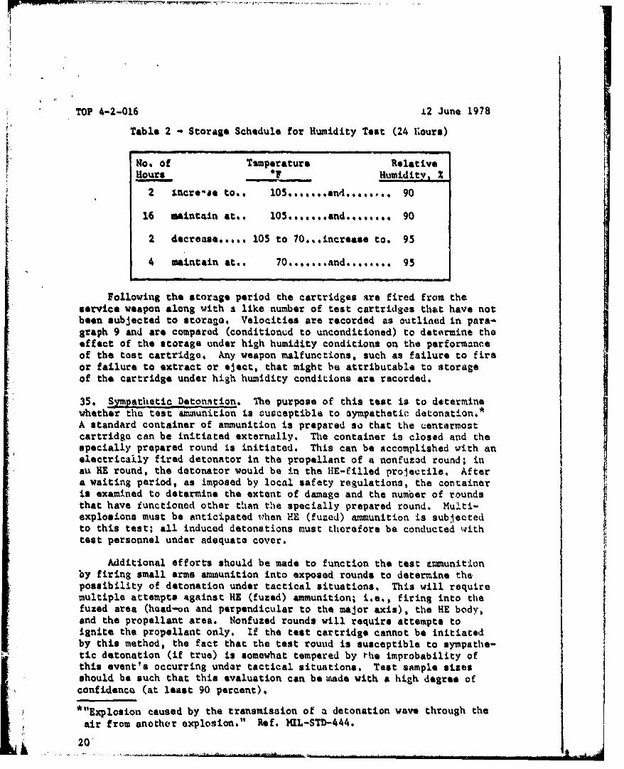
34. Temperature-Humidity. Samples of the test ammunition are subjectedto a temperature cycling and humidity test under the "warm-wet" climaticconditions of AR 70-38. The ammunition is exposed to the schedule shownin table 2 for a period of 10 days. The schedule conforms to the highhumidity-temperature cycle of TOP/MTP 4-2-820.
TOP 4-2-016 12 June 1978
Table 2 Storage Schedule for Humidity Test (24 iours)
No. of TUmperature Relative
Hours * Humidity, %
2 1vncr*-je too* 15....u.... 90
16 maintain at.. 05.......and........ 90
2 decrease..... 105 to 70..increase to. 95
4 maintain at.. 70.......and........ 95
Following the storage period the cartridges are fired from theservice weapon along with a like number of test cartridges that have notbeen subjected to storage. Velocities are recorded as outlined in pars-graph 9 and are compared (conditioned to unconditioned) to determine theeffect of the storage under high humidity conditions on the performanceof the test cartridge. Any weapon malfunctions, such as failure to fireor failure to extract or eject, that might be attributable to storageof the cartridge under high humidity conditions are recorded.
35. Sympathetic Detonation. The purpose of this test is to determinewhether the test ammunition is susceptible to sympathetic detonation.*A standard container of ammunition is prepared so that the centirmostcartridge can be initiated externally. The container is closed and thespecially prepared round is initiated. This can be accomplished with anelectrically fired detonator in the propellant of a nonfuzad round; inau HE round, the detonator would be in the HE-filled projectile. Aftera waiting period, as imposed by local safety regulations, the containeris examined to determine the extent of damage and the number of roundsthat have functioned other than the specially prepared round. Mubti-explosions must be anticipated ohen HE (fuzed) ammunition is sub.cutedto this test; all induced detonations must therefore be conducted withtest personnel under adequate cover.
Additional efforts should be made to function the test Lim~unitionby firing small arms ammunition into exposed rounds to determine thepossibility of detonation under tactical situations. This will requiremultiple attempts against HE (fuzed) ammunition; i.e., firing into thefuzed area (head-on and perpendicular to the major axis), the HE body.,and the propellant area. Nonfuzed rounds will require attempts toignite the propellant only. If the test cartridge cannot be initiatedby this method, the fact that the test round is susceptible to sympathe-tic detonation (if true) is somewhat tempered by the improbability ofthis event's occurring under tactical situations. Test sample sizesshould be such that this evaluation can be umade with a high degree ofconfidencQ (at least 90 percent).
"*"Explosion caused by the transmission of a detonation wave through the
air from another explosion." Ref. M)L-STD-444.
20
S 4 -
12 June 1978 TOP 4-2-0i6
36, Armor Penetration. ThtA test is conducted to verify that the armor-piercing round (AP) will meet the requirements established in the charac-
IlI teristics document. For a suitability test, it is necessary only toF! test against these characteristics; it might be of interest, however, to
determine additional information such ase
a. V50 - that striking velocity at which a 50 percent probabilityof target defeat at a fixed obliquity can be expected. Striking velocityis readily convertible to range.
b. 050 - that target obliquity at which a 50 percent probabilityof target defeat at a fixed range can be expected.
Testing is conducted as described in TOP 2-2-710, Vehicular Armor.
37. Helmet Penetration. Helmet-penetration tests are conducted to de-termine if the round under test will meet the criteria established in therequirements document for helmet penetration. The surface area of ahelmet contains many obliquities; however, due tb its syluetry, twoorientations, side and rear, can provide a good exposure of these many tobliquities. e
There are three ways of conducting a helmet-penetration test:
a. Emplacing helmets in an array at the required range and shootingat them.
b. Positioning the helmet close to the weapon and downloading thea-munition to the velocity level of that of the range under consideration.
4. Determining the ballistic limit of the helmets.
The type cf test will depend on the criteria to be addressed and on thetest directive.
37.1 Hlelmets Positioned at Required Range.
a. The test will be accomplished uy arraying helmets in an uprightposition (with a liner installed) on a rack. Two orientations of thehelmets (side and rear) will be exposed for projectile impacts. In theMl helmet (the present standard Army helmet) the side and rear portionscontain the thinnest and thickest areas. These two surfaces also containa reasonably comprehensive set of obliquity angles.
b. The rack for the helmets should consist of a minimum of fourshelves, with each shelf holding six to eight helmets. The array ofhelmets is placed at the specified range of interest and projectilesare fired until the needed number of valid hits are recorded.
21
TOP 4-2-016 12 June 1978
c. A valid hit is an impact in an area of the helmet where theresulting complete or partial penetration is not influenced by the con-dition of the helmet due to a prior hit in that area. A valid hit isirrespective of the angle of obliquity of the area of impact on thehelmet. The only exception is a projectile striking the bottom edge ofthe helmet; this is not a valid hit. The test is conducted at a rangewhich is usually close to the maximum effective range of the weapon andthe ammunition; therefore, the hizs on the helmets will be randomly dis-persed. A minimum of 15 valid hits for each orientation (a minimum oftwo orientations) of the helmet arm required.
d. Data relative to penetration (i.e., complete or partial in faccordance with the Navy criterion as defined in TOP 2-2-7!,O), will berecorded. Other comments, such as "cracked" or "dented", will also berecorded.
e. The approximate angle cf obliquity relative to a zone on thesurface of the helmet at the point of projectile impact will be recorded.For the M1 helmet tho data will he ctegorized into three obliquity*zones: 0* to 27', 28" to 42*, and 43* to 90*. Each zone containsapproximately 1/3 of the projected area of ie Ml helmet when it ispositioned upright on a horizontal surface. Theri will be a minimum offour valid impacts in each zone for each orientation. Two sample helmetsshould be painted (one from the side, one frow the rear) to show the threeobliqC.ty z)nes; they can then readily be used by the test director atthe teat site for determining the zone of impact. Typical photographsof sample dama-e to the helmets (and liners) will be taken and includedin the test report.
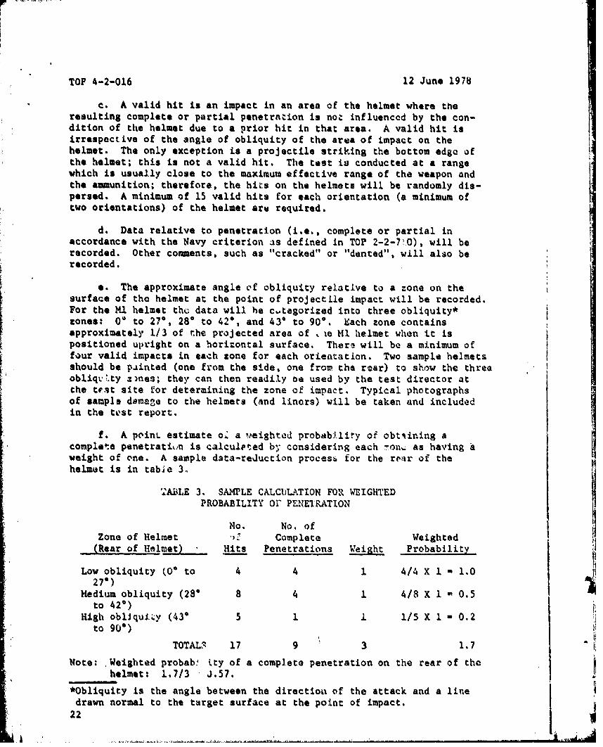
f. A point estimate oZ a weighted probab~iiy oi obtetining a i2
complete penetratiun is calculpted by considering each Ton, as having A Iweight of one. A sample data-reduction procesý for the rear of thehelmet is in tabie 3.
TA1iLE 3. SAMPLE CALCULATION FOR WEIGHTEDPROBABILITY O PENETRATION
No. No. ofZone of Helmet Complete Weighted
(Rear of Helmet) Hits Penetrations Weight Probability
Low obliquity (0 to 4 4 1 4/4 X 1 - 1.0 aiI27*)
Medium obliquity (28" 8 4 1 4/8 X 1 - 0.5to 420)
High obliquity (43" 5 1 1. 1/5 X 1 - 0.2to 900)
TOTAL3 17 9 3 1.7Note: Weighted probab! Uty of a complete penetration on the rear of the
helmet: 1.7/3 -. 57.*Obliquity is the angle between the directioai of the attack and a line
drawn normal to the target surface at the point of impact.22
A . . .
/
12 June 1978 TOP 4-2-016
g. The weighted values for the side and the rear of the helmet areaveraged to give the final point estimate of the probability of a com-plete penetration of a random hit on the helmet.
h. A confidence interval on the overall probability of penetrationcan also be calculated, using the assumption that the number of penetra-tions per number of valid hits is a binomial random variable. If the pro-bability of the helmet not being penetrated is required, rather thanpenetration, it can be calculated by subtracting the probability of pene-tration from 1.0. A confidence interval of this probability can also becalculated. Different types of helmets can be compared with regard toeither of the above probabilities through the use of a chi-square statisticfor comparing the equality-of-penetrction rate (or protuition rate).
37.2 Helmets Positioned Close to the Gun.
a. If remaining-velocity data are available for the ammunitionbeing tested, the propellant in the cartridges can be downloaded to givean impact velocity of the projectile on a targe close to the gun equalto that occurring at the range under considerac on. The helmets arepositioned close to the gun and it is usually possible to impact on thehelmet at a location within an inch of the aiming point; thus, very fewprojectiles and very few helmets are required to provide a good samplingof the various obliquities of the helmet.
b. Before firing at the helmets, projectiles are fired at the re- Iduced propellant charge to ensure that the velocities are correct and thatexcessive yaw does not occur at the short range at which the projectilewill hit the helmet. If yaw, measured by firing through yaw cards ofphotographic paper, exceeds 10' consistently, a short-range test cannotbe conducted. If at least 1/3 of the projectiles show acceptable yaw,i ,of 5° or less, this test method can be ua•ed.
c. As in the testing at actual ranges, two orientations of the
helmet will be tested: side and rear. The helmet with a liner will beplaced on a stand or rack, which tilts it slightly forward (about 5') togive the effect of the projectile trajectory at actual ranges. Five pro-Jectiles are fired into each of the three zones of the helmet, as pre-viously described in paragraph 37.1e. Judgement is used in eliminatingunnecessary firing (e.g., if there are no complete penetrations againstthe medium obliquity area, it may be assumed that there will be nocomplete penetrations against the high-obliquity area).
,eu Velocity and yaw data will be recorded on each projectile firedto ensure the correct velocity and less than 5* yaw for all valid impacts.The data are recorded and a point estimate of the probability of pene-tration of the helmet is determined as described in paragraph 37.1f.
23

TOP 4-2-016 12 June 1978
37.3 Ballistic Limits of Helmets. Ballistic limit data for penetrationof helmets can be obtained by using the up-and-down firittg t6chniquedescribed in TOP 2-2-710.
38. Fungus. This test is conducted to determine whether fungus,streptomycetea, or bacteria to which the test ammunition will be exposedunder tactical situations will degrade the performance. If all componeaitsare certified for fungus resistance, no fungus test is necessary perTOP/MTP 4-2-8181 otherwise, samples of the test ammunition arQ subjectedto the applicable portions of a fungus resistence test as outlined inthat document. Following the fungus exposure, the cartridges are wipedclean and examined fcr any damage; the rounds are then fired from theservice weapon and functioning observed. Fuzed ammunition is fired toimpact against a target determined to reliably function the fuse asestablished in the fuze sensitivity test (par& 18b). Tracer ammunitionis fired for daylight trace observation as described in paragraph 29.Cartrige cases are examined following the firing test to detarmine anyfiring deiocts resulting from the exposure,
39. iuman Factors Engineering. Throughout all.phases of fuzed and non-fuzed a&munition testing the test item is evaluated for man-item relation-ships. This includes, but is not limited to- ease of handling; readilyrecognizable markings on the various types of asmuunitioa (i.e., HE, A?,discarding-sabot, etc.); affects of flash, smoke, blast and toxic fumes;and other factors as applicable. This evaluation also applies duringthe testing of blank and dummy or training ammunition outlined in 40 and41 below.
40. Blank Ammunition. Blank ammunition is used during training eaer-
cises to simulate the firing of live ammunition and must therefore po3sesscertain characteristics of the related live cartridge. Blank ammunition,along with the associated blank-firing attachment (BFA), must reasonably
reproduce the noise, flash, smoke and weapon-functioning characteristicsof the live cartridge. The blank cartridge and BFA must also meet safety
.requirements in that (a) no fragments should be expelled forward of theweapon and (b) the physical appearance of the blank should be easily 1pdiscernible from that of a live round to preclude the inadvertent firingof a live cartridge with the BFA attached. To check for these require-ments the tests outlined in 40.1 through 40.4 below are conducted,
40.1 Function and Casualty. Testing is conducted from the appropriateservice weapon with the BFA attached. The firing is similar to thatdescribed in paragraph 17. A single witness screen is placed in theline of fire and at the minimum distance at which unburned propellantexpulsion is permitted (as prescribed in the applicable requirementsdocument). This witness screen should be of 0.0025-inch-thick kraftpaper.
40.2 Wea~on.Compatibtlity. The blank cartridge and associated BFA aresubjected to a weapon compatibility test as described in paragraph 25,
24
12 June 1978 TOP 4-2-0M6
40.3 Noise Lqvel. The tests conducted are identical to those in para-graph 23. Noise levels are compared with those of the service cartridgefor compliance with the applicable requirements documents.
40.4 Flash and Smoke. The tests are as described in paragraphs 30 and31. Service cartridges are fired for comparative performance character-istics.
40.5 U. Specific designs of individual cartridges may requirespecial testing such as determining the results of tmamoring with theblank cartridges or associated blank firing devices.
41. D~umm or Training Ammunition. Dummy or training ammunltion is usedto check the service weapon by hand cycling and in some instances tointerrupt burst firings by linking a cartridge in an extended belt oflive ammunition to cause cessation of firing at prescribed intervals.A du•y or training cartridge should therefore possess the characteris-tics of the service cartridge in relation to weight, center of gravity,and profile; it should also be earily discernible from the live car-tridge in ap-earance. Testing should be limited to checking thosecharacteristics plus determination of serviceable life by use in theintended service weapon (either by hand cycling or as burst fireinterrupter).
41.1 InapectIon. The rounds are inspected for noticeable def,.cts,damage, and markings that readily distinguish the dummy or traininground from the representative live round. I41.2 Physical Measurements, A sample of dummy rounds are inspacted andcritical areas such as those listed under paragraph 7a determined (i.e.,weight, center of gravity, length, etc.). These data are compared withthose for the representative live round.
41,3 'Serviceable Life. A. sample of the dummy rounds ar3 cycled (h.andor otherwise) through the nervice weapon until the cartridges becomeunserviceable or unti.l the life requirements of the dunmy rounds asspecified in the appl.icable requirements document have been met. Duringthe evaluation, if possible, the cy-ling parts of the weapon under normalspring tensions are allowed to feed, simulate firing, and extract therounds,
Recommnded changes to this publication should be forwarded toCounander, U. S. Axmy Test and Evalua&ýon Command, ATTN:tDRSTE-AD-M, Aberdeen Proving Ground, Md, 21005. Technical infor-mation may be obtained from the preparing activity: Commander,U. S. Arny Aberdeen Proving Ground, ATTN: STEAP-MT-M, AberdeenProving Ground, Md. 21005. Additional copies are available fromthe Defense Documentation Center, Cameron Station, Alexandria,Va. 22314. This document is identified by the accession number(AD No.) printed on the first page.
25
a
TOP 4-2-016 12 June 1978
APPENDIXREFERENCES
1. AR 70-38, "Research, Development, Test, and Evaluation of Materialfor Extreme Climatic Conditions."
2.' AMCR 715-505, "Ammunition Ballistic Acceptance Test Methods."
3. MIL-STD-210B, "Climatic Extremes for Military Equipment."
4. MIL-STD-331, "Fuze and Fuze Components, Environmental and PerformanceTest for."
5. MIL-STD-444, "Nomenclature and Definitions in th Ammunition Area."
6. MIL-STD-636, "Visual Inspection Standards for Small Arms M-munitionThrough Caliber .50."
7. MIL-STD-810C, "Environmental Test Methods."
8. MIL-STD-1474, "Noise Limits for Army Materiel."
2I
S~26
JUWICUIY CLASSIVICAhION OF I KIS PAQ6 (11thn Dot* gntowed)READ INSTRUCTIONS
REPORT DOCUMENTATION PAGE -RMFORE COMPLETING P'ORNWINORT NUMuIR1 .GOT ACCI&SION NO. 3.EICIPIRNT'S CATALOG NUMBER
TOP 4-2-016 ___________
4. TITLE (and Subtlils) S. Type or REPORT 6 PERIOD COVERED
US ARMY TEST AND EVALUATION COMMANDTEST OPERATIONS PROCED"'RES "AMMUNITION, SMALL ARMS" EROMNOI.RPOTUUR
7. AU!HOR(o) 0. CONTRAZT1 OR =RANTi NUMSER(sC)
6. PERAORMING ORGANIZATION HAMS AND ADDRESS to. PROGRIAM EMNT, PROJE.CT, TASKAREA A WRK UNIT NUMOCERS
US Army Abardaen Proving Ground (STEAP-MT.-M)
Aberdeen Proving Ground, Maryland 21005 M ý1-I Il. CONTROLLING OFF~ICE HAMS AND ADDRESS 19. REPOPMDATE12 June 1978
US Army Test and Evaluation Comman~d (DRSTE-AD-M) ~NNEO AI
Aberdeen Proving Ground, Maryland 21005 27t-4. M3141TORING A13KNCY HAMS AOOn1SS(IU dift*Ie r0e m Conltroling ffile.) IS. SECURITY CLASS. (of this report)
UnclassifiedIS. OU~SSIPIICATION/ OOWNORAOING
VS. DISTRI3UflON STAT[MIENT (of this floport) _
Approved for public release; distributicn unlimited.
17. D~ISTRIBUTION STATEMENT (of the eboteect entered In Block 20. Uf different from Roepr.,)
IS.-supPLUNCNTARY NOTES
it. KEZY WOflOS' (Continue an reversesie .It. nc~esaary and Idoe.ttify by' block nhumber)
Axguunitiono Small Arms
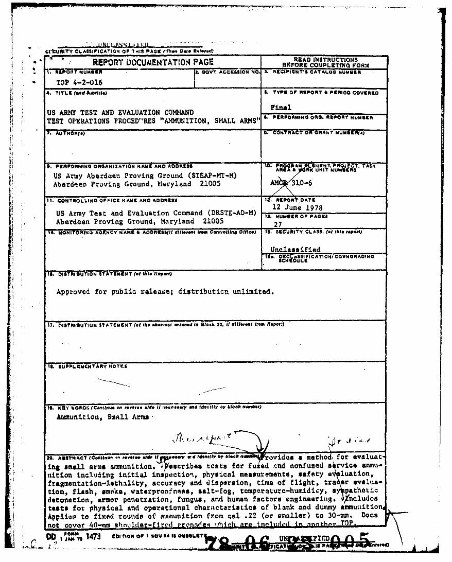
20t ATACT (ConlEupf -k- roveM etAr It &*myV d itIdentify br btock num"4rovides a metihod-, for evaluatin& small arms ammunition. 'OTtescribes tests for fuied nnd nonfuzed a rvice amimu-nition incl.uding initial inspectiont, physical measurements, safety a luation,fragmentation-lethality, accuracy and dispersion, time of flight, tra er eval.ua-tion, flash, smoks, waterproofntass, salt-fog, tempa.raturo-huntidicy, a patheticdetonation, armor penutration, fungus, and human factors engineeritig. /ncludcstests for physical and operational characteristics of blank and d%:mmy aimnutitionApplies~ to fixed rounds of ammunition from cal .22 (or smaller) to 30-mm. Docs'not covor 40-mm 9hni1 e=Urd -. n~Q TOE.-
PON" 1473 tocnow op I NOV s% is o T 1sA. SPU F I ED Yw v