lesson1 introduction
TRANSCRIPT
8/2/2019 Lesson1 Introduction
http://slidepdf.com/reader/full/lesson1-introduction 1/32
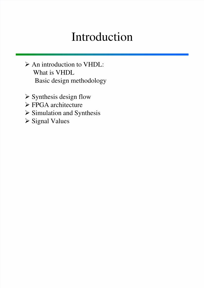
Introduction
An introduction to VHDL:
What is VHDL
Basic design methodology
Synthesis design flow
FPGA architecture Simulation and Synthesis
Signal Values
8/2/2019 Lesson1 Introduction
http://slidepdf.com/reader/full/lesson1-introduction 2/32
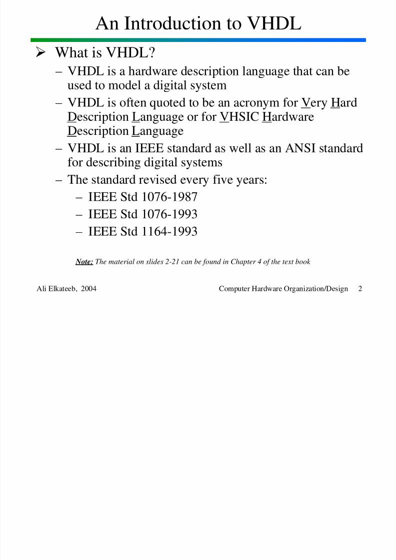
An Introduction to VHDL
Ali Elkateeb, 2004 Computer Hardware Organization/Design 2
What is VHDL?– VHDL is a hardware description language that can be
used to model a digital system
– VHDL is often quoted to be an acronym for Very HardDescription Language or for VHSIC HardwareDescription Language
– VHDL is an IEEE standard as well as an ANSI standardfor describing digital systems
– The standard revised every five years:
– IEEE Std 1076-1987
– IEEE Std 1076-1993
– IEEE Std 1164-1993
Note: The material on slides 2-21 can be found in Chapter 4 of the text book
8/2/2019 Lesson1 Introduction
http://slidepdf.com/reader/full/lesson1-introduction 3/32
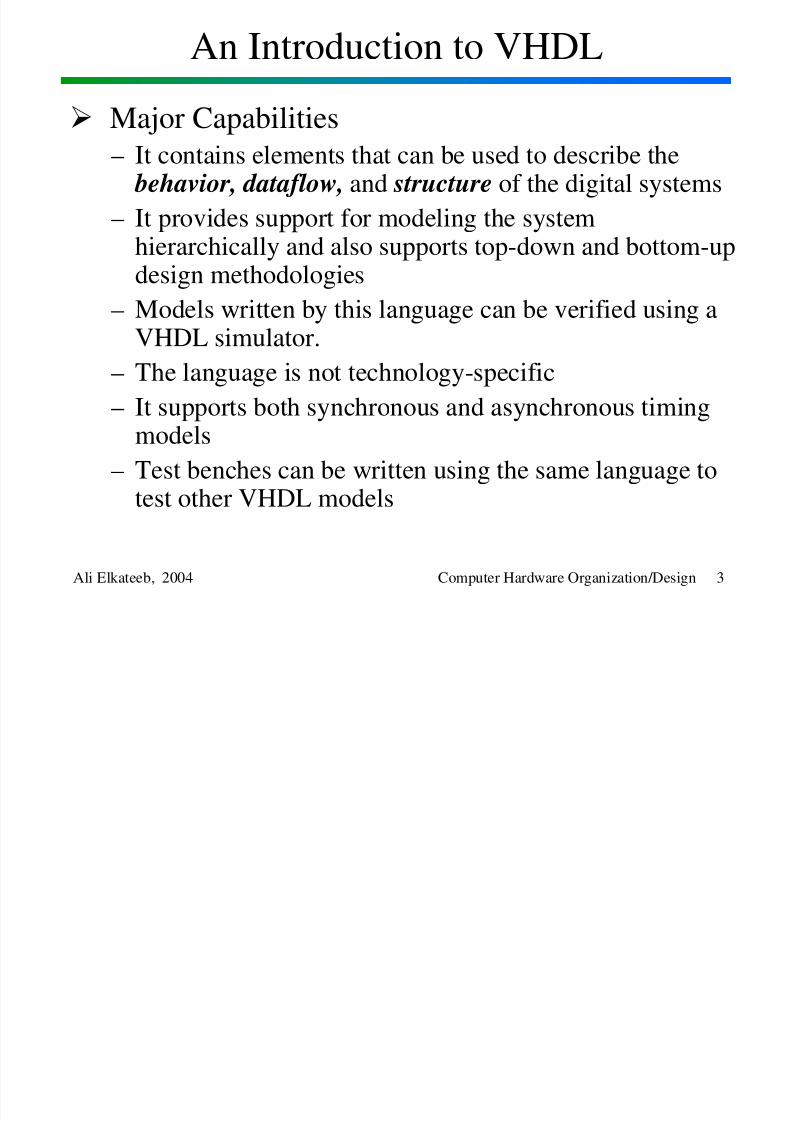
An Introduction to VHDL
Ali Elkateeb, 2004 Computer Hardware Organization/Design 3
Major Capabilities
– It contains elements that can be used to describe the behavior, dataflow, and structure of the digital systems
– It provides support for modeling the systemhierarchically and also supports top-down and bottom-updesign methodologies
– Models written by this language can be verified using aVHDL simulator.
– The language is not technology-specific
– It supports both synchronous and asynchronous timingmodels
– Test benches can be written using the same language totest other VHDL models
8/2/2019 Lesson1 Introduction
http://slidepdf.com/reader/full/lesson1-introduction 4/32
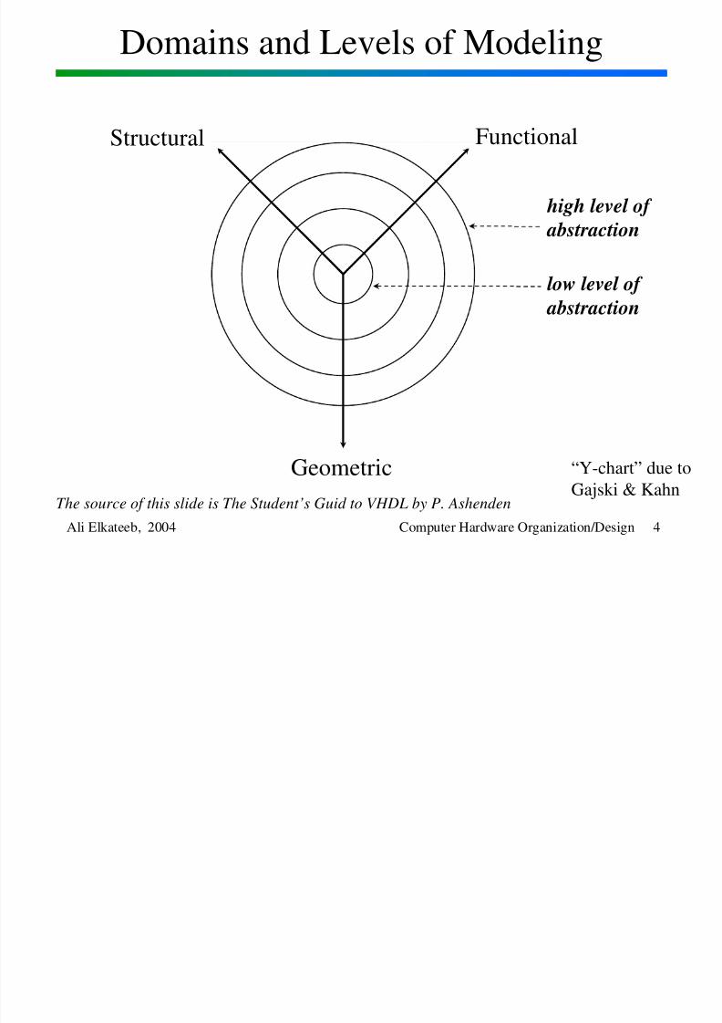
Domains and Levels of Modeling
Ali Elkateeb, 2004 Computer Hardware Organization/Design 4
high level of
abstraction
FunctionalStructural
Geometric “Y-chart” due toGajski & Kahn
low level of abstraction
The source of this slide is The Student’s Guid to VHDL by P. Ashenden
8/2/2019 Lesson1 Introduction
http://slidepdf.com/reader/full/lesson1-introduction 5/32
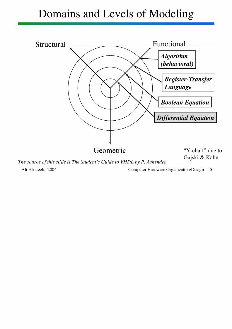
Domains and Levels of Modeling
Ali Elkateeb, 2004 Computer Hardware Organization/Design 5
FunctionalStructural
Geometric “Y-chart” due toGajski & Kahn
Algorithm
(behavioral)
Register-Transfer
Language
Boolean Equation
Differential Equation
The source of this slide is The Student’s Guide to VHDL by P. Ashenden
8/2/2019 Lesson1 Introduction
http://slidepdf.com/reader/full/lesson1-introduction 6/32
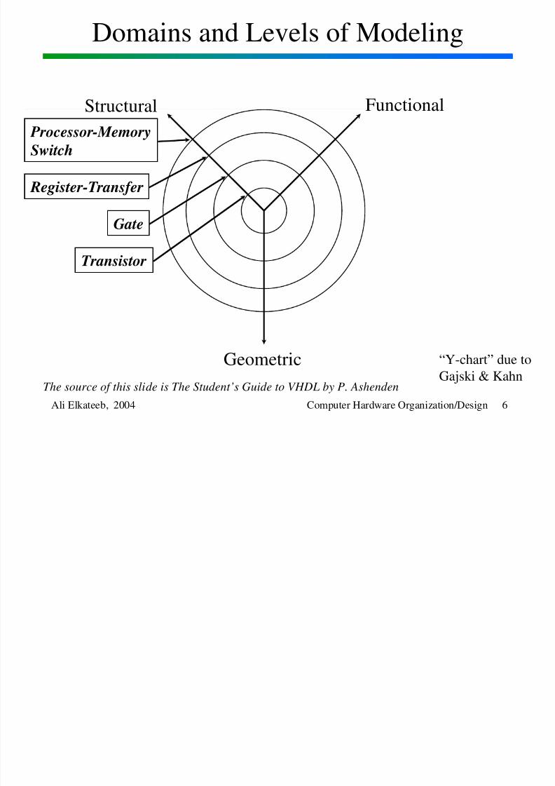
Domains and Levels of Modeling
Ali Elkateeb, 2004 Computer Hardware Organization/Design 6
FunctionalStructural
Geometric “Y-chart” due toGajski & Kahn
Processor-Memory
Switch
Register-Transfer
Gate
Transistor
The source of this slide is The Student’s Guide to VHDL by P. Ashenden
8/2/2019 Lesson1 Introduction
http://slidepdf.com/reader/full/lesson1-introduction 7/32
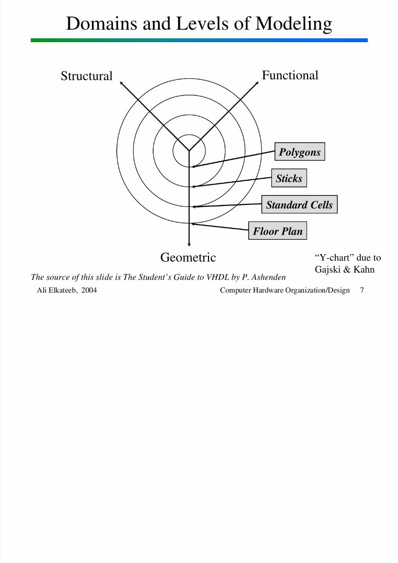
Domains and Levels of Modeling
Ali Elkateeb, 2004 Computer Hardware Organization/Design 7
FunctionalStructural
Geometric “Y-chart” due toGajski & Kahn
Polygons
Sticks
Standard Cells
Floor Plan
The source of this slide is The Student’s Guide to VHDL by P. Ashenden
8/2/2019 Lesson1 Introduction
http://slidepdf.com/reader/full/lesson1-introduction 8/32
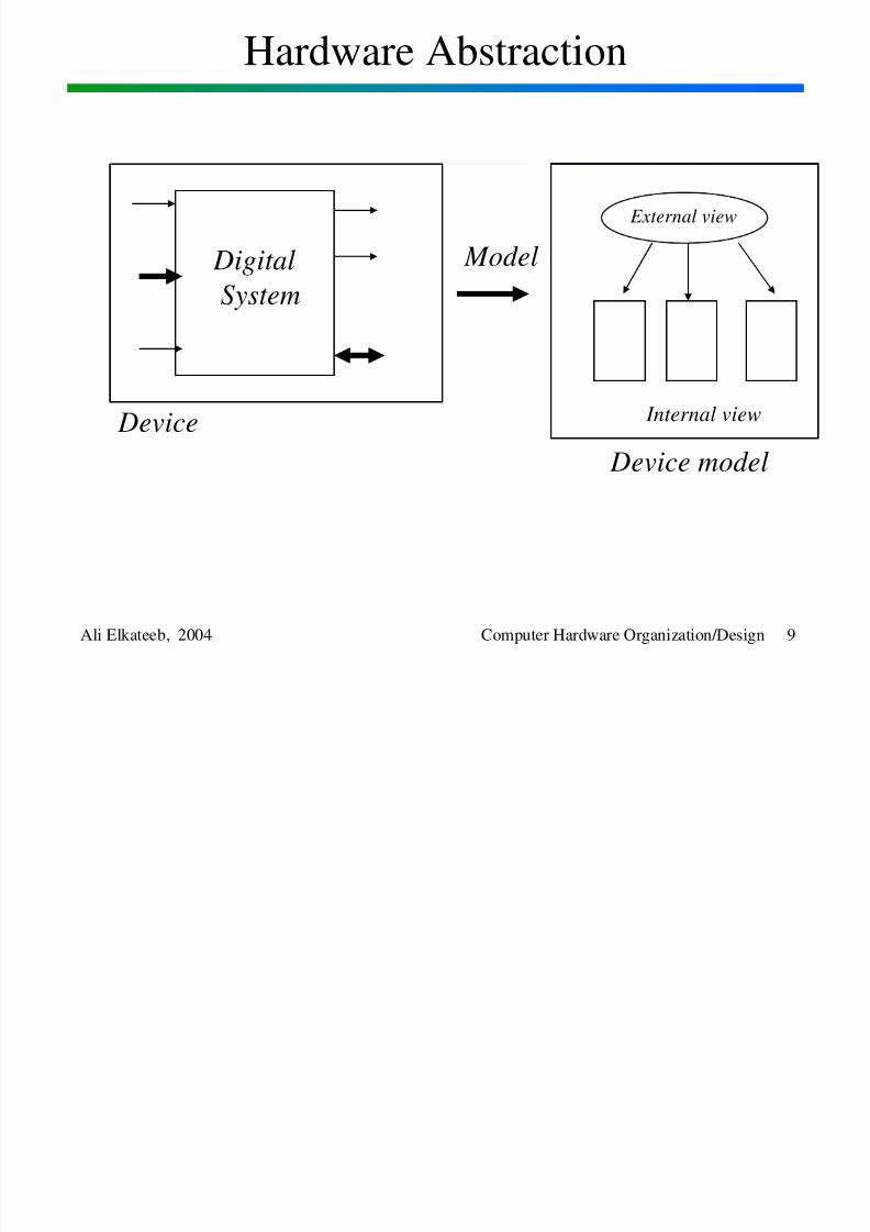
Hardware Abstraction
Ali Elkateeb, 2004 Computer Hardware Organization/Design 8
– VHDL is used to describe a model for a digital hardware device
– Each model specifies the external view of the device and oneor more internal views
– Internal view: specifies the functionality or structure of the
device– External view: specifies the interface of the device through
which it communicates with the other
models in its environment
8/2/2019 Lesson1 Introduction
http://slidepdf.com/reader/full/lesson1-introduction 9/32
Hardware Abstraction
Ali Elkateeb, 2004 Computer Hardware Organization/Design 9
Digital
System
Device
External view
Internal view
Device model
Model
8/2/2019 Lesson1 Introduction
http://slidepdf.com/reader/full/lesson1-introduction 10/32
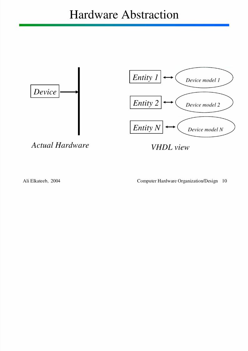
Hardware Abstraction
Ali Elkateeb, 2004 Computer Hardware Organization/Design 10
Device model 1 Entity 1
Device
Device model 2 Entity 2
Device model N Entity N
Actual Hardware VHDL view
8/2/2019 Lesson1 Introduction
http://slidepdf.com/reader/full/lesson1-introduction 11/32
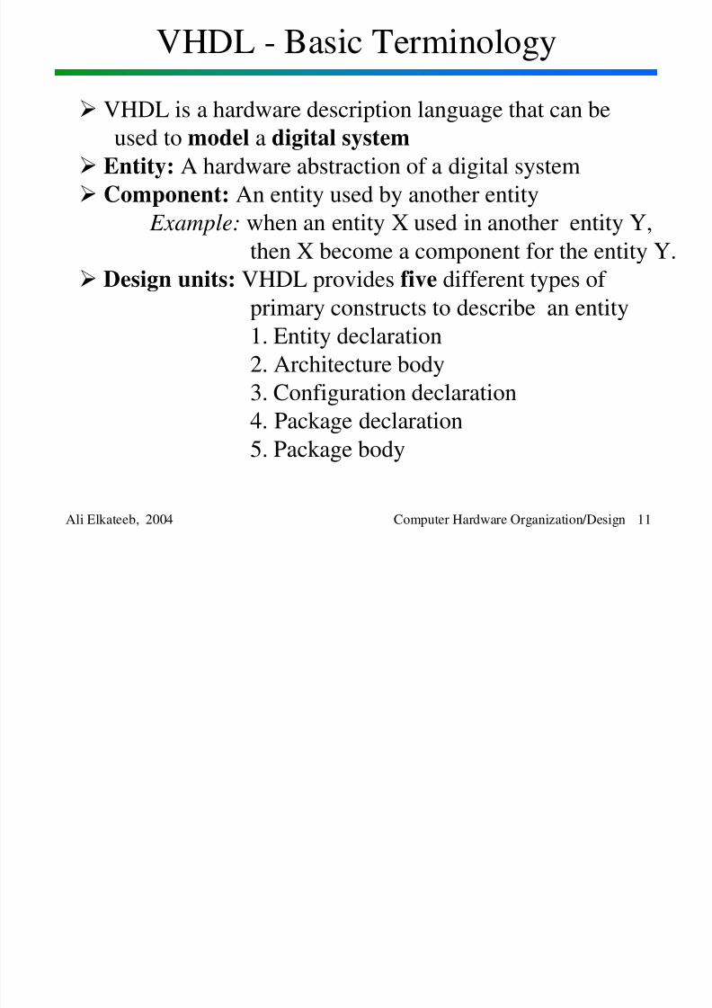
VHDL - Basic Terminology
Ali Elkateeb, 2004 Computer Hardware Organization/Design 11
VHDL is a hardware description language that can be
used to model a digital system
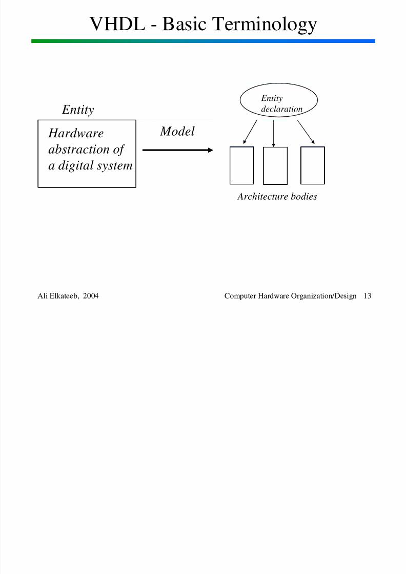
Entity: A hardware abstraction of a digital system
Component: An entity used by another entity Example: when an entity X used in another entity Y,
then X become a component for the entity Y.
Design units: VHDL provides five different types of primary constructs to describe an entity
1. Entity declaration
2. Architecture body3. Configuration declaration
4. Package declaration
5. Package body
8/2/2019 Lesson1 Introduction
http://slidepdf.com/reader/full/lesson1-introduction 12/32
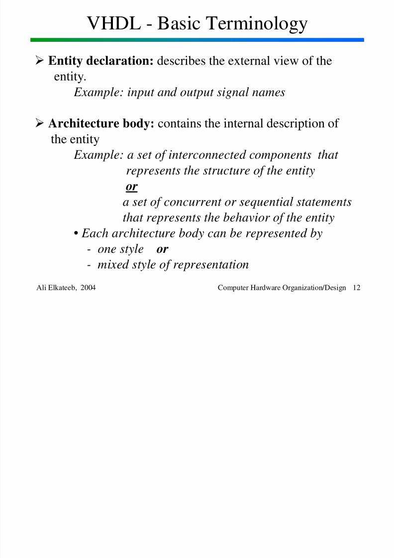
VHDL - Basic Terminology
Ali Elkateeb, 2004 Computer Hardware Organization/Design 12
Entity declaration: describes the external view of the
entity.
Example: input and output signal names
Architecture body: contains the internal description of
the entity
Example: a set of interconnected components that represents the structure of the entity
or
a set of concurrent or sequential statementsthat represents the behavior of the entity
• Each architecture body can be represented by
- one style or
- mixed style of representation
8/2/2019 Lesson1 Introduction
http://slidepdf.com/reader/full/lesson1-introduction 13/32
VHDL - Basic Terminology
Ali Elkateeb, 2004 Computer Hardware Organization/Design 13
Entity
declaration Entity
Model Hardware
abstraction of
a digital system
Architecture bodies
8/2/2019 Lesson1 Introduction
http://slidepdf.com/reader/full/lesson1-introduction 14/32
VHDL - Basic Terminology
Ali Elkateeb, 2004 Computer Hardware Organization/Design 14
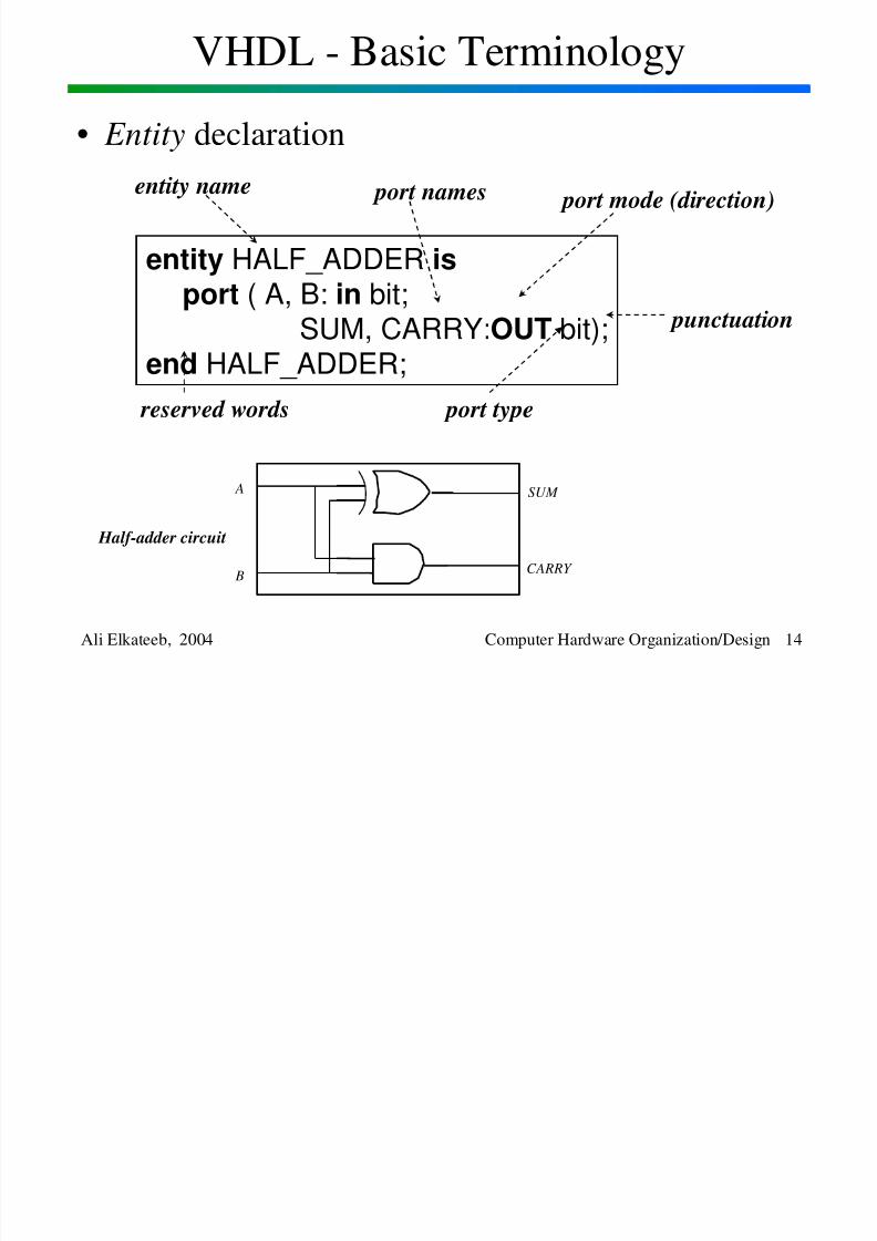
• Entity declaration
entity HALF_ADDER isport ( A, B: in bit;
SUM, CARRY:OUT bit);end HALF_ADDER;
entity name port names port mode (direction)
port type reserved words
punctuation
SUM
CARRY
A
B
Half-adder circuit

8/2/2019 Lesson1 Introduction
http://slidepdf.com/reader/full/lesson1-introduction 15/32
VHDL - Basic Terminology
Ali Elkateeb, 2004 Computer Hardware Organization/Design 15
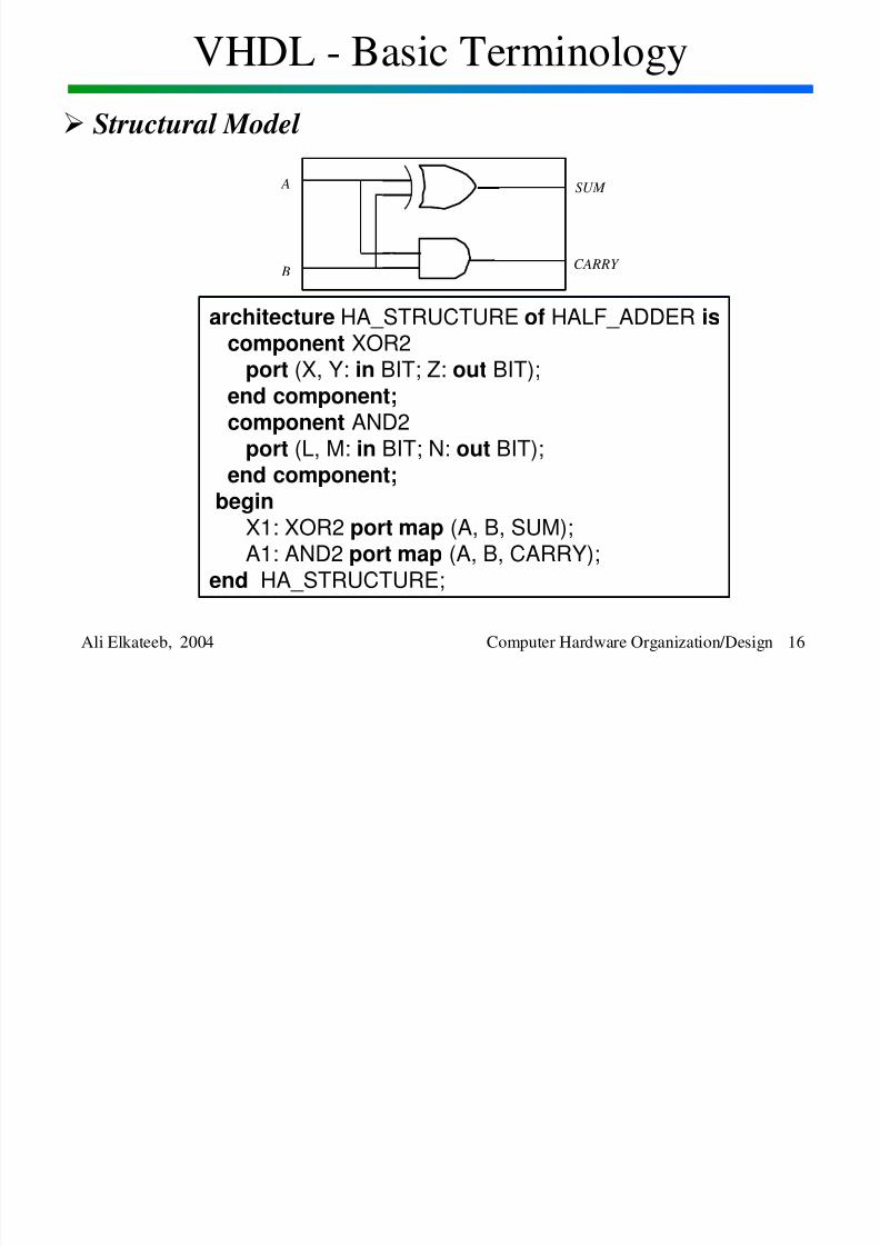
• Architecture Body
- Represents the internal details of an entity
- An architecture body can use any of the following modeling
styles:
1. Set of interconnected components
(structural model)2. Set of concurrent assignment statements
(dataflow model)
3. Set of sequential assignment statements(behavior model)
4. Any combination of the above
(mixed model)
8/2/2019 Lesson1 Introduction
http://slidepdf.com/reader/full/lesson1-introduction 16/32
VHDL - Basic Terminology
Ali Elkateeb, 2004 Computer Hardware Organization/Design 16
Structural Model
SUM
CARRY
A
B
architecture HA_STRUCTURE of HALF_ADDER is
component XOR2port (X, Y: in BIT; Z: out BIT);
end component;component AND2
port (L, M: in BIT; N: out BIT);end component;
beginX1: XOR2 port map (A, B, SUM);A1: AND2 port map (A, B, CARRY);
end HA_STRUCTURE;
8/2/2019 Lesson1 Introduction
http://slidepdf.com/reader/full/lesson1-introduction 17/32
VHDL - Basic Terminology
Ali Elkateeb, 2004 Computer Hardware Organization/Design 17
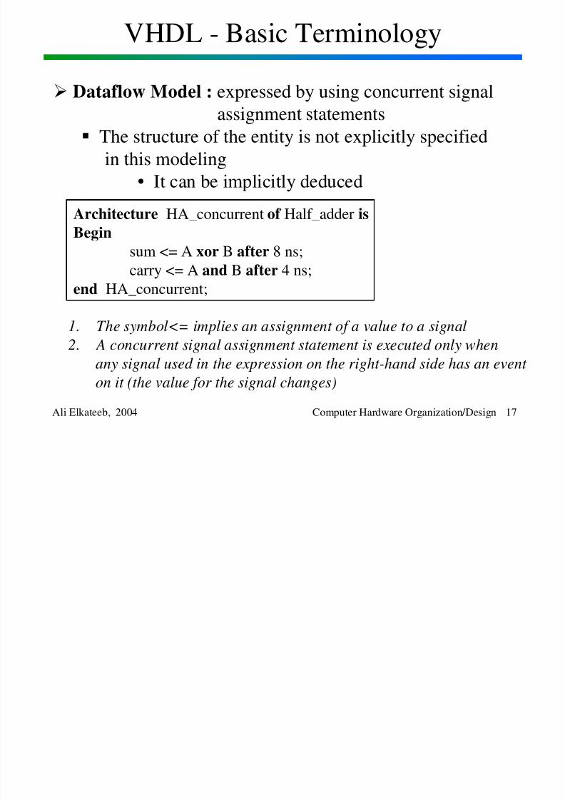
Dataflow Model : expressed by using concurrent signal
assignment statements
The structure of the entity is not explicitly specified
in this modeling
• It can be implicitly deduced
Architecture HA_concurrent of Half_adder is
Begin
sum <= A xor B after 8 ns;
carry <= A and B after 4 ns;
end HA_concurrent;
1. The symbol<= implies an assignment of a value to a signal
2. A concurrent signal assignment statement is executed only when
any signal used in the expression on the right-hand side has an event
on it (the value for the signal changes)
8/2/2019 Lesson1 Introduction
http://slidepdf.com/reader/full/lesson1-introduction 18/32
VHDL - Basic Terminology
Ali Elkateeb, 2004 Computer Hardware Organization/Design 18
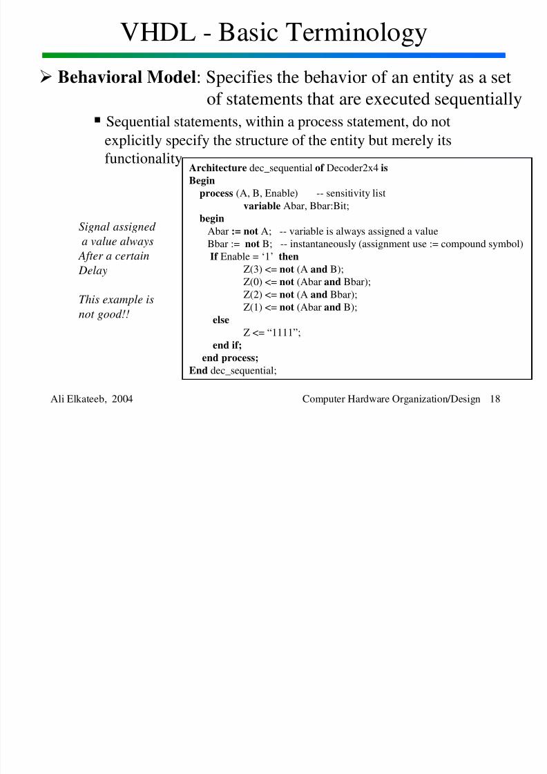
Behavioral Model: Specifies the behavior of an entity as a setof statements that are executed sequentially
Sequential statements, within a process statement, do not
explicitly specify the structure of the entity but merely itsfunctionality
Architecture dec_sequential of Decoder2x4 is
Begin
process (A, B, Enable) -- sensitivity list
variable Abar, Bbar:Bit;
beginAbar := not A; -- variable is always assigned a value
Bbar := not B; -- instantaneously (assignment use := compound symbol)
If Enable = ‘1’ then
Z(3) <= not (A and B);
Z(0) <= not (Abar and Bbar);
Z(2) <= not (A and Bbar);
Z(1) <= not (Abar and B);
else
Z <= “1111”;
end if;
end process;End dec_sequential;
Signal assigned
a value always
After a certain
Delay
This example is
not good!!
8/2/2019 Lesson1 Introduction
http://slidepdf.com/reader/full/lesson1-introduction 19/32
VHDL - Basic Terminology
Ali Elkateeb, 2004 Computer Hardware Organization/Design 19
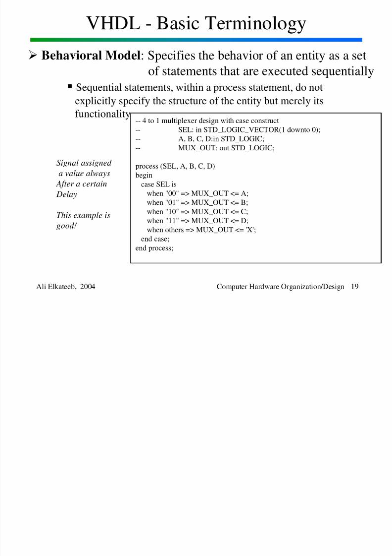
Behavioral Model: Specifies the behavior of an entity as a setof statements that are executed sequentially
Sequential statements, within a process statement, do not
explicitly specify the structure of the entity but merely itsfunctionality
-- 4 to 1 multiplexer design with case construct
-- SEL: in STD_LOGIC_VECTOR(1 downto 0);
-- A, B, C, D:in STD_LOGIC;
-- MUX_OUT: out STD_LOGIC;
process (SEL, A, B, C, D)
begin
case SEL is
when "00" => MUX_OUT <= A;
when "01" => MUX_OUT <= B;
when "10" => MUX_OUT <= C;
when "11" => MUX_OUT <= D;
when others => MUX_OUT <= 'X';
end case;
end process;
Signal assigned
a value always
After a certain
Delay
This example is
good!
8/2/2019 Lesson1 Introduction
http://slidepdf.com/reader/full/lesson1-introduction 20/32
VHDL - Basic Terminology
Ali Elkateeb, 2004 Computer Hardware Organization/Design 20
Mixed Model
Will be discussed after the behavioral model section
8/2/2019 Lesson1 Introduction
http://slidepdf.com/reader/full/lesson1-introduction 21/32
Synthesis Design Flow For FPGAs
Ali Elkateeb, 2004 Computer Hardware Organization/Design 21
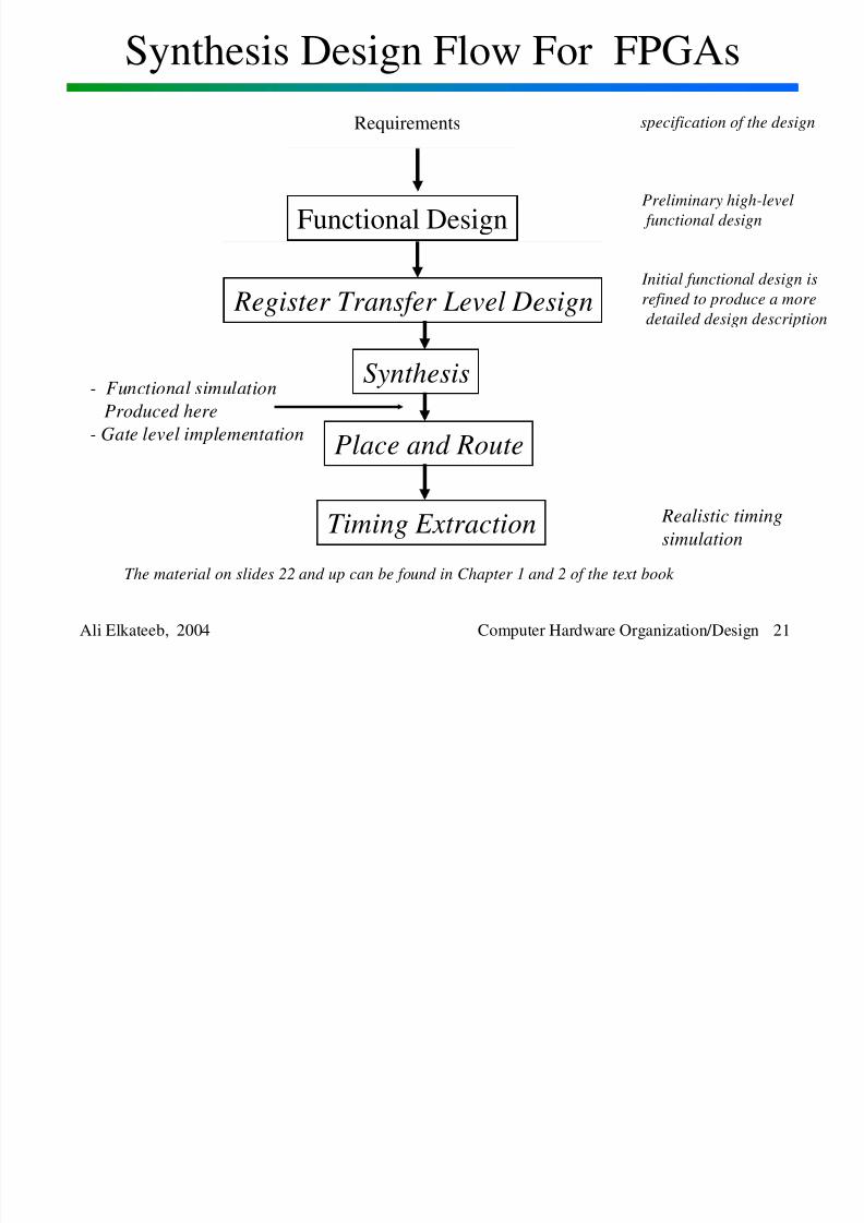
Requirements specification of the design
Preliminary high-level
functional design
Functional Design
Initial functional design is
refined to produce a more
detailed design description Register Transfer Level Design
Synthesis- Functional simulation
Produced here
- Gate level implementation
Place and Route
Realistic timing
simulationTiming Extraction
The material on slides 22 and up can be found in Chapter 1 and 2 of the text book
8/2/2019 Lesson1 Introduction
http://slidepdf.com/reader/full/lesson1-introduction 22/32
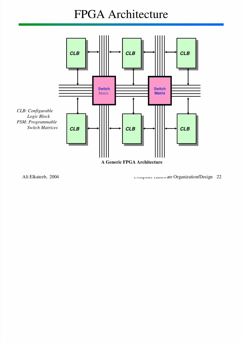
FPGA Architecture
Ali Elkateeb, 2004 Computer Hardware Organization/Design 22
CLB CLB
CLB CLB
CLB CLB
CLB CLB
SwitchMatrix
CLB CLB
CLB CLB
SwitchMatrix
A Generic FPGA Architecture
CLB: Configurable
Logic Block
PSM: Programmable
Switch Matrices
8/2/2019 Lesson1 Introduction
http://slidepdf.com/reader/full/lesson1-introduction 23/32
FPGA Architecture
Ali Elkateeb, 2004 Computer Hardware Organization/Design 23
CLB
CLB
CLB
CLB
SwitchMatrix
Programmable
InterconnectI/O Blocks (IOBs)
ConfigurableLogic Blocks (CLBs)
D Q
SlewRate
Control
PassivePull-Up,
Pull-Down
Delay
Vcc
OutputBuffer
InputBuffer
Q D
Pad
D QSD
RD
EC
S/R
Control
D Q
SD
RDEC
S/R
Control
1
1
F'
G'
H'
DIN
F'
G'
H'
DIN
F'
G'
H'
H'
HFunc.Gen.
GFunc.Gen.
FFunc.Gen.
G4G3G2G1
F4F3F2F1
C4C1 C2 C3
K
Y
X
H1 DIN S/R EC
8/2/2019 Lesson1 Introduction
http://slidepdf.com/reader/full/lesson1-introduction 24/32
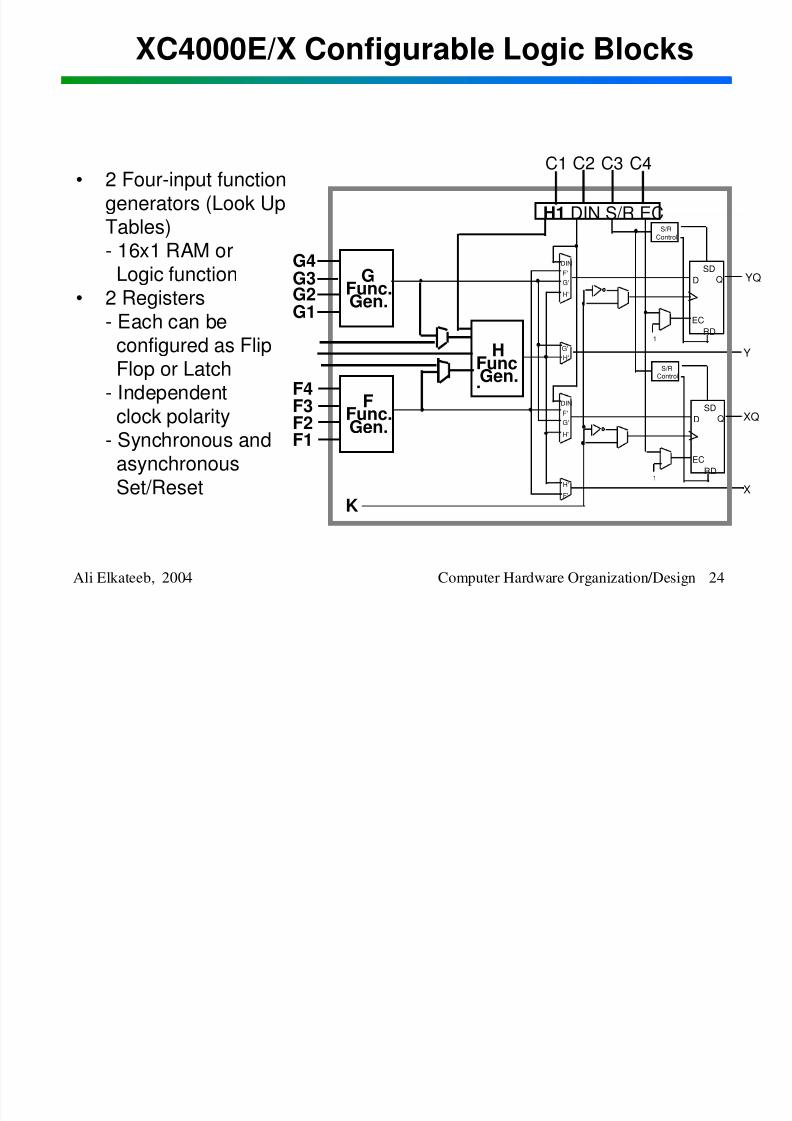
XC4000E/X Configurable Logic Blocks
Ali Elkateeb, 2004 Computer Hardware Organization/Design 24
D QSD
RD
EC
S/R
Control
D Q
SD
RD
EC
S/RControl
1
1
F'
G'
H'
DIN
F'
G'
H'
DIN
F'
G'
H'
H'
HFunc.Gen.
GFunc.Gen.
F
Func.Gen.
G4G3G2
G1
F4F3F2F1
C4C1 C2 C3
K
YQ
Y
XQ
X
H1 DIN S/R EC
• 2 Four-input function
generators (Look UpTables)- 16x1 RAM orLogic function
• 2 Registers
- Each can beconfigured as FlipFlop or Latch
- Independent
clock polarity- Synchronous andasynchronousSet/Reset
8/2/2019 Lesson1 Introduction
http://slidepdf.com/reader/full/lesson1-introduction 25/32
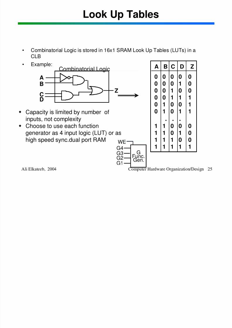
Look Up Tables
Ali Elkateeb, 2004 Computer Hardware Organization/Design 25
Capacity is limited by number ofinputs, not complexity
Choose to use each functiongenerator as 4 input logic (LUT) or ashigh speed sync.dual port RAM
• Combinatorial Logic is stored in 16x1 SRAM Look Up Tables (LUTs) in aCLB
• Example: A B C D Z
0 0 0 0 00 0 0 1 0
0 0 1 0 00 0 1 1 10 1 0 0 10 1 0 1 1
. . .1 1 0 0 01 1 0 1 01 1 1 0 01 1 1 1 1
Combinatorial Logic
AB
CD
Z
GFunc.Gen.
G4
G3G2G1
WE
8/2/2019 Lesson1 Introduction
http://slidepdf.com/reader/full/lesson1-introduction 26/32
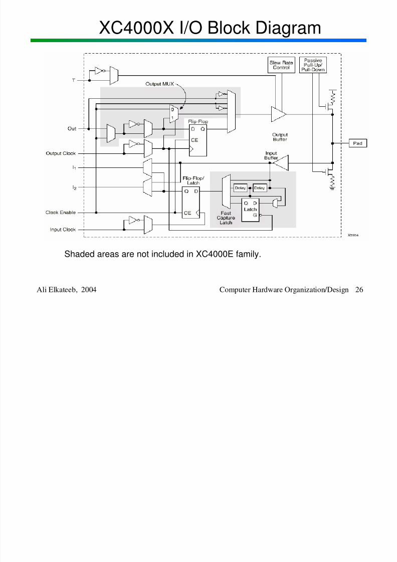
Ali Elkateeb, 2004 Computer Hardware Organization/Design 26
XC4000X I/O Block Diagram
Shaded areas are not included in XC4000E family.
Chip St ructure
8/2/2019 Lesson1 Introduction
http://slidepdf.com/reader/full/lesson1-introduction 27/32
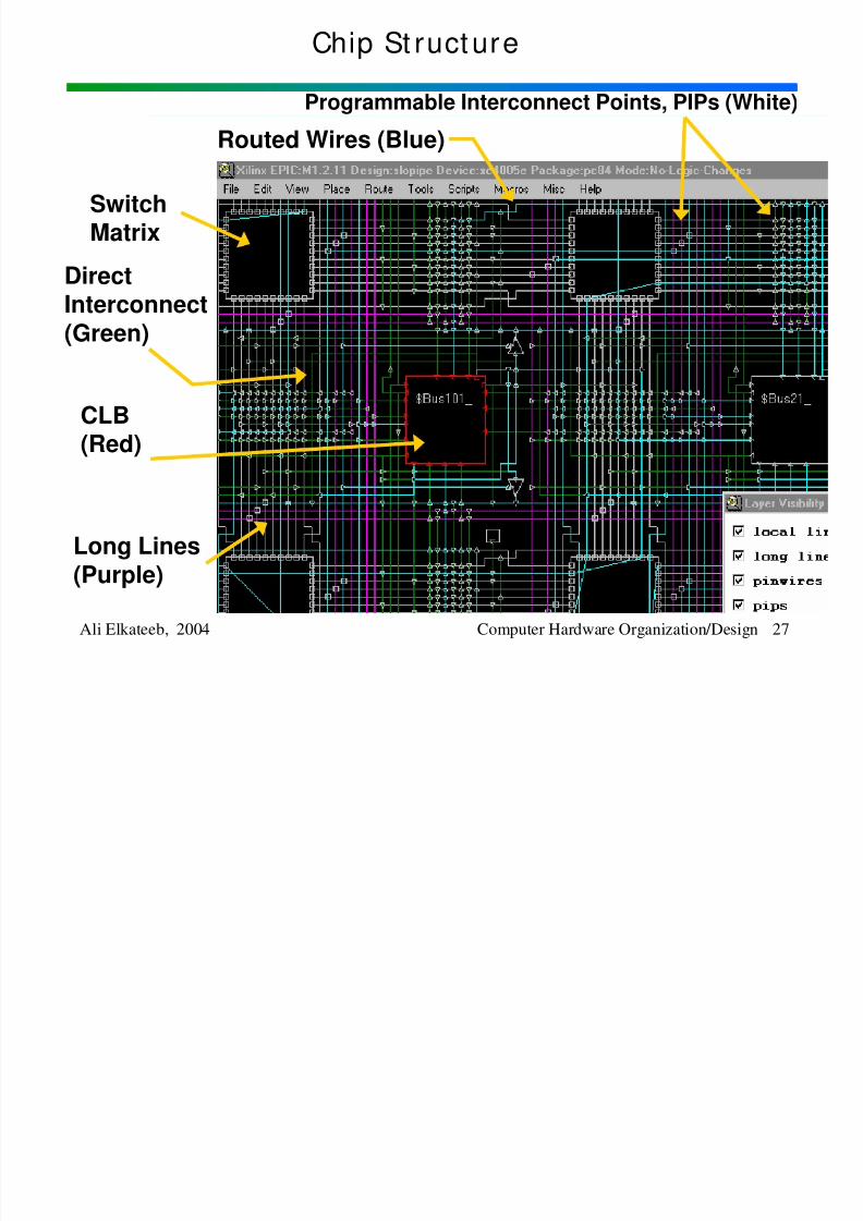
Chip St ructure
Ali Elkateeb, 2004 Computer Hardware Organization/Design 27
CLB(Red)
Switch
Matrix
Long Lines
(Purple)
DirectInterconnect
(Green)
Routed Wires (Blue)
Programmable Interconnect Points, PIPs (White)
Sim l ti
8/2/2019 Lesson1 Introduction
http://slidepdf.com/reader/full/lesson1-introduction 28/32
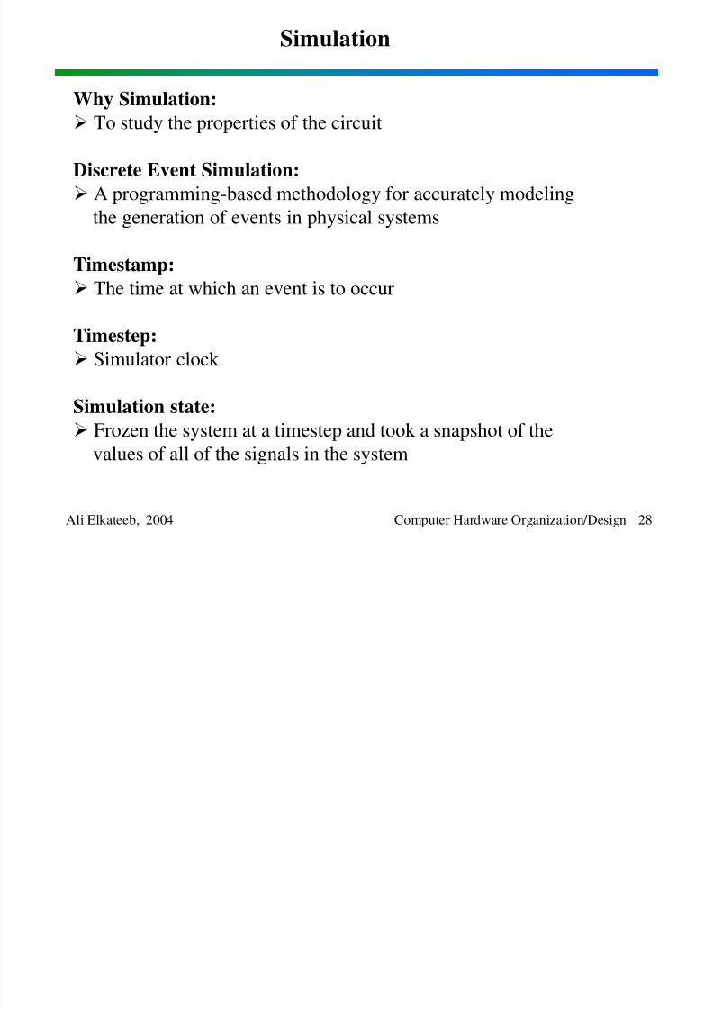
Simulation
Ali Elkateeb, 2004 Computer Hardware Organization/Design 28
Why Simulation: To study the properties of the circuit
Discrete Event Simulation:
A programming-based methodology for accurately modelingthe generation of events in physical systems
Timestamp:
The time at which an event is to occur
Timestep:
Simulator clock
Simulation state:
Frozen the system at a timestep and took a snapshot of the
values of all of the signals in the system
Simulation
8/2/2019 Lesson1 Introduction
http://slidepdf.com/reader/full/lesson1-introduction 29/32
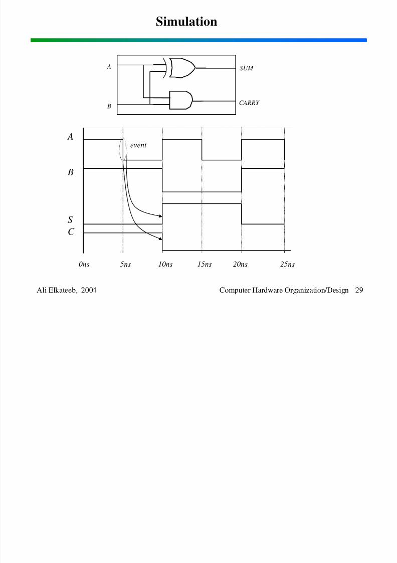
Simulation
Ali Elkateeb, 2004 Computer Hardware Organization/Design 29
SUM
CARRY
A
B
0ns 5ns 10ns 15ns 20ns 25ns
event A
B
S
C
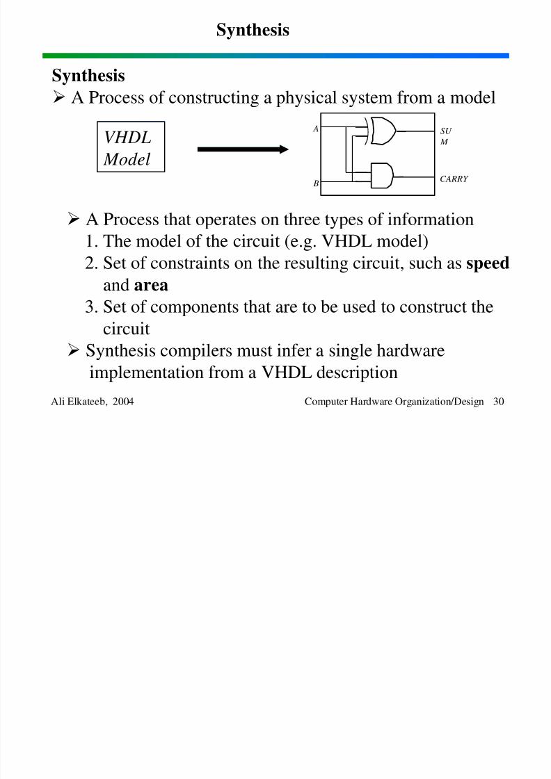
Synthesis
8/2/2019 Lesson1 Introduction
http://slidepdf.com/reader/full/lesson1-introduction 30/32
Synthesis
Ali Elkateeb, 2004 Computer Hardware Organization/Design 30
SU
M
CARRY
A
B
Synthesis A Process of constructing a physical system from a model
VHDL
Model
A Process that operates on three types of information1. The model of the circuit (e.g. VHDL model)
2. Set of constraints on the resulting circuit, such as speed
and area3. Set of components that are to be used to construct the
circuit
Synthesis compilers must infer a single hardware
implementation from a VHDL description
Signal Values
8/2/2019 Lesson1 Introduction
http://slidepdf.com/reader/full/lesson1-introduction 31/32
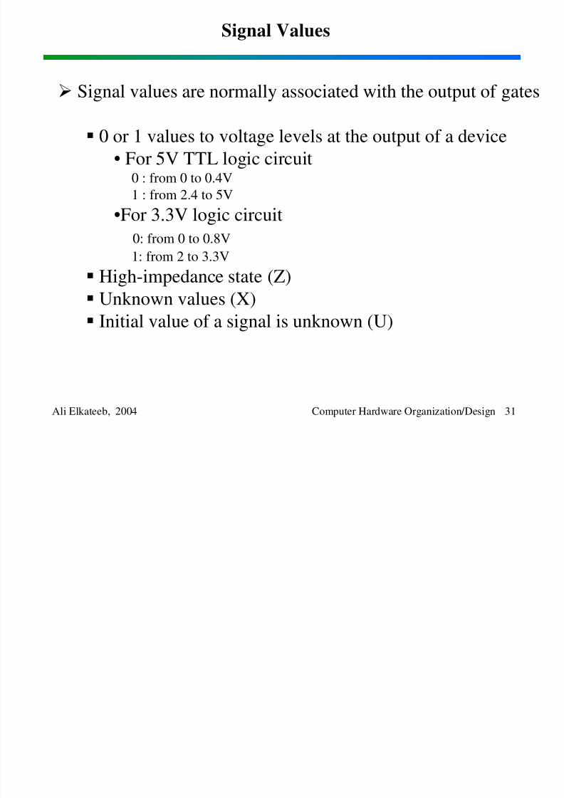
Signal Values
Ali Elkateeb, 2004 Computer Hardware Organization/Design 31
Signal values are normally associated with the output of gates
0 or 1 values to voltage levels at the output of a device
• For 5V TTL logic circuit0 : from 0 to 0.4V
1 : from 2.4 to 5V
•For 3.3V logic circuit
0: from 0 to 0.8V
1: from 2 to 3.3V
High-impedance state (Z)
Unknown values (X) Initial value of a signal is unknown (U)
Signal Values
8/2/2019 Lesson1 Introduction
http://slidepdf.com/reader/full/lesson1-introduction 32/32
Signal Values
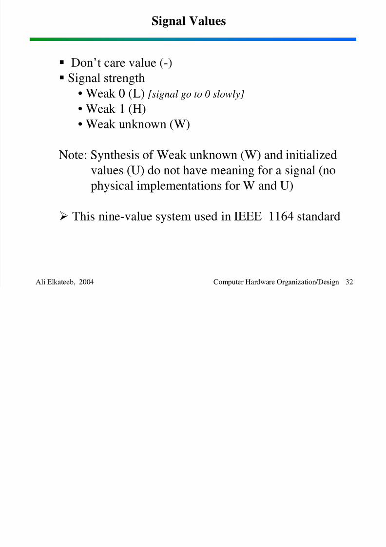
Ali Elkateeb, 2004 Computer Hardware Organization/Design 32
Don’t care value (-)
Signal strength
• Weak 0 (L) [signal go to 0 slowly]
• Weak 1 (H)
• Weak unknown (W)
Note: Synthesis of Weak unknown (W) and initializedvalues (U) do not have meaning for a signal (no
physical implementations for W and U)
This nine-value system used in IEEE 1164 standard