lesson b5 sewage sludge treatment - tuhh a · pdf filelesson b5 sewage sludge treatment ......
TRANSCRIPT
EMWATER E-LEARNING COURSE PROJECT FUNDED BY THE EUROPEAN UNION LESSON B5: SEWAGE SLUDGE TREATMENT
Page 1 of 23
Lesson B5
SEWAGE SLUDGE TREATMENT
Authors:
Holger Pabsch
Claudia Wendland
Institute of Wastewater Management
Hamburg University of Technology
Keywords sewage sludge, stabilisation, sludge thickening, sludge dewatering, sludge pumping, digestion
EMWATER E-LEARNING COURSE PROJECT FUNDED BY THE EUROPEAN UNION LESSON B5: SEWAGE SLUDGE TREATMENT
Page 2 of 23
Table of Content
Overview and summary of this Lesson 3
1. Sewage sludge quantity and characteristics 4
2. Sludge pumping systems 5
3. Sludge stabilisation 7
3.1 Simultaneous aerobic stabilisation 7 3.2 Mesophilic anaerobic digestion 8 3.3 Aerobic digestion 11 3.4 Alkaline Stabilisation 12
4. Thickening/ dewatering of Sludge 14
4.1 Dimensioning of a static thickener 15 4.2 Dewatering 16
5. Sludge Disposal and Agricultural Utilisation 20
6. Exercises 21
7. References and further Information 23

EMWATER E-LEARNING COURSE PROJECT FUNDED BY THE EUROPEAN UNION LESSON B5: SEWAGE SLUDGE TREATMENT
Page 3 of 23
Overview and summary of this Lesson
Sludge originates from the process of treatment of wastewater and is separated from the treatment process by sedimentation or flotation. Sewage sludge consists of water and solids that can be divided into mineral and organic solids. The quantity and characteristics of sludge depend very much on the treatment processes. Most of the pollutants that enter the wastewater get adsorbed to the sewage sludge. Therefore, sewage sludge contains pathogens (and heavy metals, many organic pollutants pesticides, hydrocarbons etc. if the sewage contains industrial influence). Sludge is, however, rich in nutrients such as nitrogen and phosphorous and contains valuable organic matter that is useful if soils are depleted or subject to erosion.
Options for sludge treatment include stabilisation, thickening, dewatering, drying. Sewage sludge is stabilised to reduce pathogens, to eliminate offensive odours and to inhibit, reduce or eliminate the potential for putrefaction. Moreover, stabilisation is used for volume reduction, production of usable gas (methane), and improving the dewaterability of sludge. Thickening, dewatering, drying are used to remove water from sewage sludge. Several techniques are used in dewatering devices for removing moisture. A technique close to nature and very effective is dewatering in drying beds. The principal advantages of drying beds are low costs, infrequent attention required, and high solids content in the dried product, especially in arid climates. Disadvantages are the large space required, effects of climatic changes on drying characteristics, labour-intensive sludge removal, insects and potential odours.
In this lesson source and characteristics of sewage sludge as well as methods of its treatment are discussed briefly. Natural treatment systems are focused. Also different options for sludge disposal are compared.
EMWATER E-LEARNING COURSE PROJECT FUNDED BY THE EUROPEAN UNION LESSON B5: SEWAGE SLUDGE TREATMENT
Page 4 of 23
1. Sewage sludge quantity and characteristics The sources of solids in a wastewater treatment plant vary according to the type of plant and its method of operation. Usually there are two sources of sewage sludge within the treatment process:
• solids in the affluent to the treatment plant which consist of settable organic matter and mineral substances which are not trapped in the grit chamber.
• biomass that has grown on the organic load (BOD)
Sewage sludge is separated from the treatment process by sedimentation or flotation. In many cases there is a primary sedimentation (primary sludge) and secondary sedimentation (secondary sludge). Smaller treatment plants often have only one sedimentation tank in which the entire sludge is separated from the treated water.
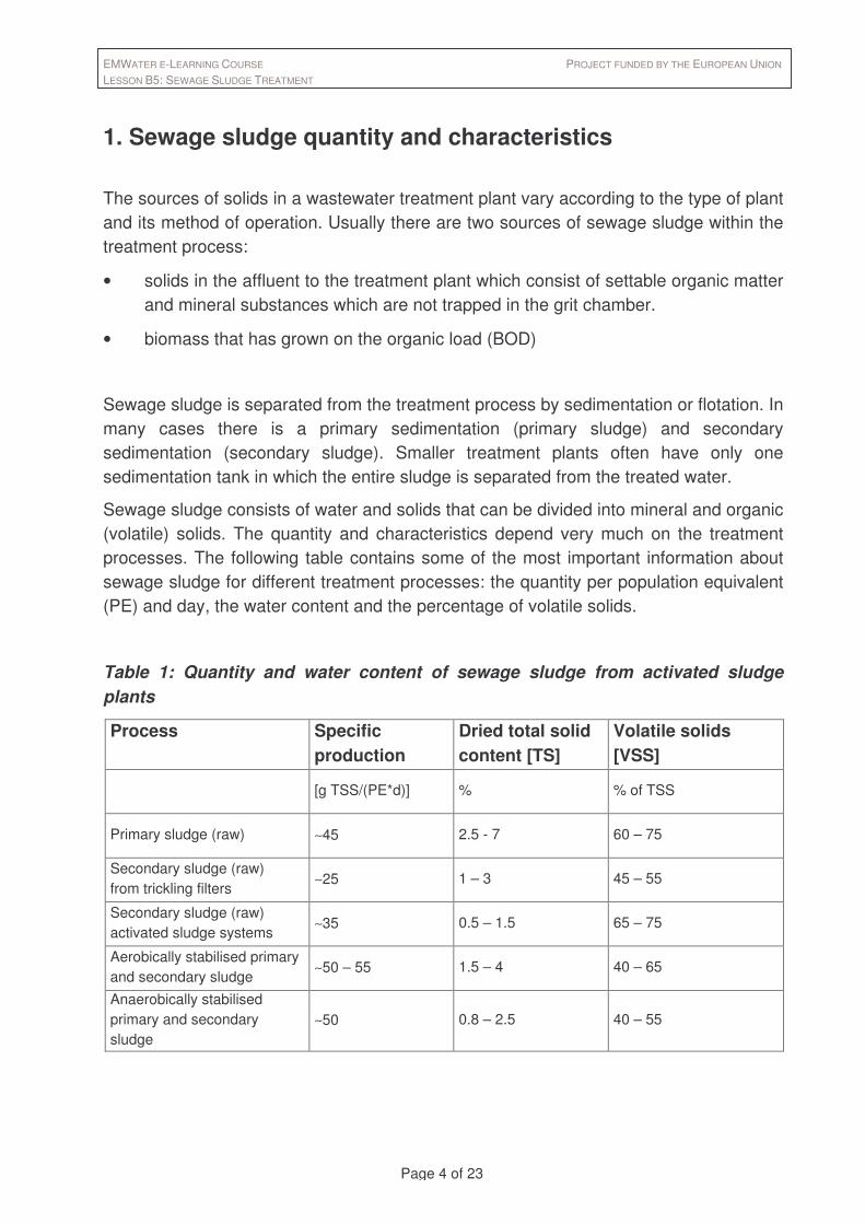
Sewage sludge consists of water and solids that can be divided into mineral and organic (volatile) solids. The quantity and characteristics depend very much on the treatment processes. The following table contains some of the most important information about sewage sludge for different treatment processes: the quantity per population equivalent (PE) and day, the water content and the percentage of volatile solids.
Table 1: Quantity and water content of sewage sludge from activated sludge plants
Process Specific production
Dried total solid content [TS]
Volatile solids [VSS]
[g TSS/(PE*d)] % % of TSS
Primary sludge (raw) ∼45 2.5 - 7 60 – 75
Secondary sludge (raw) from trickling filters
∼25 1 – 3 45 – 55
Secondary sludge (raw) activated sludge systems
∼35 0.5 – 1.5 65 – 75
Aerobically stabilised primary and secondary sludge
∼50 – 55 1.5 – 4 40 – 65
Anaerobically stabilised primary and secondary sludge
∼50 0.8 – 2.5 40 – 55

EMWATER E-LEARNING COURSE PROJECT FUNDED BY THE EUROPEAN UNION LESSON B5: SEWAGE SLUDGE TREATMENT
Page 5 of 23
As you can see, the biggest amount of sludge is produced by primary treatment which, of course highly depends on the hydraulic retention time in the primary sedimentation tank.
A big advantage of anaerobic wastewater treatment is the production of much less sludge than in aerobic systems because of low growing rates of anaerobic bacteria. If the primary and secondary treatment is replaced by an anaerobic step like a UASB reactor the sludge production is less than 10% of the aerobic system (see also lesson B3).
Among the unspecified “mineral” and “organic” solids are hazardous materials. Most of the pollutants that enter the wastewater get adsorbed to the sewage sludge. Therefore, sewage sludge contains heavy metals, many organic pollutants (pesticides, hydrocarbons etc.) and pathogens. The concentration depends on the industry, workshops or hospitals connected to the sewer system and their efforts to reduce the emission.
A very important class of substances are nutrients. Sewage sludge contains nitrogen (av. 2.6 % of TS), phosphorus (av. 2 % of TS), potash (av. 0.2 % TS). These elements, various trace elements and organic substances make sewage sludge a valuable fertilizer.
The purpose of sludge treatment is, besides hygienisation, to change the figures in the table above. Easily biodegradable volatile solids cause odour, that is why they should be reduced by stabilisation. A high water content (→ low percentage of total solids) makes the handling difficult, causes high cost for transportation and storage and should therefore be reduced.
2. Sludge pumping systems Sludge produced in wastewater treatment plants must be conveyed from point to point in the plant in conditions ranging from a watery sludge to a thick sludge. Sludge may also be pumped off-site for long distances for treatment. For each type of sludge and pumping application a different type of pump may be needed.
Pumps can generally be divided into centrifugal pumps (with different impellers) and displacement pumps (progressive cavity (see figure1), rotary lobe, piston). Centrifugal pumps are suitable for high flow rates and low solid contents, the problem is choosing a proper size. At any given speed, centrifugal pumps operate well only if the pumping head is within a relatively narrow range. The variable nature of sludge, however, causes pumping heads to change. The selected pump must have sufficient clearance to pass the solids without clogging. Usual centrifugal pumps can cause the break up of

EMWATER E-LEARNING COURSE PROJECT FUNDED BY THE EUROPEAN UNION LESSON B5: SEWAGE SLUDGE TREATMENT
Page 6 of 23
flocculent particles in activated sludge. Good experiences in this respect have been made with screw-shaped impellers.
Table 2: Suitable pumps for sludge
Type of pump Applicable for: Advantages Disadvantages
Centrifugal pumps thin sludge (max. 2.5 - 3%)
Nonclog activated sludge high volume, good efficiency
potential clogging (rags etc.)
Recessed impeller sludge with solids or grit
lower efficiency
Chopper primary sludge reduces clogging lower efficiency
Progressing cavity pump thickened sludge dewatered sludge
defined flow rates acts as check valve
can run dry grit can cause high stator wear
Rotary lobe pump thickened sludge dewatered sludge
defined flow rates acts as check valve
grit can cause high lobe wear
Piston pump thickened sludge dewatered sludge
high pressure discontinuous flow
Screw pump activated sludge good efficiency limited height high capital costs space requirement
Screw dried sludge
conveyor belt dewatered sludge dried sludge
good efficiency high capital costs space requirement
Displacement pumps can convey dewatered sludge up to 30% TS. Displacement pumps have a fixed ratio between revolutions and flow rate. Any pipeline obstruction causes damages to the pipeline or pump. Generally check valves are not necessary. For primary sludge, a grinder normally proceeds progressive cavity pumps.

EMWATER E-LEARNING COURSE PROJECT FUNDED BY THE EUROPEAN UNION LESSON B5: SEWAGE SLUDGE TREATMENT
Page 7 of 23
Figure 1: Scheme of a progressive cavity pump
3. Sludge stabilisation Sewage sludge is stabilised to reduce pathogens, to eliminate offensive odours and to inhibit, reduce or eliminate the potential for putrefaction. The success in achieving these objectives is related to a reduction of the organic (volatile) fraction or the addition of chemicals to the sludge to render it unsuitable for the survival of microorganisms.
In addition to the health an aesthetic reasons mentioned above, stabilisation is used for volume reduction, production of usable gas (methane), and improving the dewaterability of sludge.
In some cases a sludge disinfection is required to meet the standard for agricultural reuse (see 3.4 to 3.6).
3.1 Simultaneous aerobic stabilisation
A very simple method to achieve a stabilised sludge is the simultaneous aerobic stabilisation. To provide growth conditions for the microorganisms for an adequate wastewater treatment, a certain solid retention time (→ sludge age) is necessary. It differs due to the temperature and the demanded nitrogen removal between approx. 4 and 12 days. If the sludge age is extended up to more than 20 days (Germany: 25 due to low temperatures) the content of organic matter, especially easily degradable organic
EMWATER E-LEARNING COURSE PROJECT FUNDED BY THE EUROPEAN UNION LESSON B5: SEWAGE SLUDGE TREATMENT
Page 8 of 23
matter, is reduced and the sludge is stabilised. This concept generally eliminates a primary sedimentation, solids from the effluent are treated in the aeration tank. This process approach is attractive for smaller communities, where space is not an issue and less complex operation is preferred. The large aeration tank volume provides good equalisation at high flow and loading occurrences and a high quality effluent is produced.
A disadvantage is the higher energy demand caused by the extension of the aerated time. The increased capital costs for the larger aeration tanks are in general more than compensated by the omitted facilities for an external stabilisation.
3.2 Mesophilic anaerobic digestion
Anaerobic digestion is among the oldest processes used for the stabilisation of sewage sludge. Anaerobic digestion involves the decomposition of organic and, on a low level, inorganic matter (principally sulphate) in the absence of oxygen. The main products are CO2 and CH4 (methane). With this digester gas most of the energy needs for the plant operation can be met. Methane is highly relevant to global climate change, thus uncovered digesters without methane use (and burning to CO2) should be avoided. According to the four-step model the following processes are involved:
1. hydrolysis: particulate material is converted to soluble compounds that can then be hydrolysed further to simple monomers
2. acidogenesis: in this step, also called fermentation, amino acids, sugars and higher (long chain) fatty acids are degraded further to volatile fatty acids, alcohols, acetic acid, hydrogen, carbon dioxide, ammonia and sulphide.
3. acetogenesis: the volatile fatty acids and alcohols are degraded to acetic acid, hydrogen and carbon dioxide
4. methanogenesis: this step is carried out by a group of bacteria called methanogens. Two groups are involved in methane production. One group split acetic acid into methane and carbon dioxide. The second group, termed hydrogen-utilising methanogens, use hydrogen as the electron donor and carbon dioxide as an electron acceptor to produce methane.
See also figure 2.

EMWATER E-LEARNING COURSE PROJECT FUNDED BY THE EUROPEAN UNION LESSON B5: SEWAGE SLUDGE TREATMENT
Page 9 of 23
Figure 2: Four-step model of methane production
The microorganisms responsible for methane production are strict obligate anaerobes. They need darkness and heat speeds up their activity. Heated digesters are operated at 37°C (mesophilic) or 55°C (thermophilic).
As the four step model above shows, hydrogen is formed during the fermentative steps and consumed during methanogenesis. If process upsets occur and the methanogenic organisms do not utilise the hydrogen produced fast enough, the acetogenesis will be slowed with the accumulation of volatile fatty acids in the anaerobic digester and a possible reduction in pH. If an accumulation of volatile fatty acids is observed, the organic load has to be reduced. On the other hand the reaction
4H2 + CO2 → CH4 + 2H2O
needs a certain H2 - partial pressure to take place. Still the methanogenesis is the limiting step.
The important difference to the aerobic metabolism, where carbon dioxide is produced, is that highly energetic source substances are split into carbon dioxide and methane with high energy content. This makes obvious that the energy gain from the anaerobic reactions is very low. In consequence the growth of anaerobic bacteria is comparatively slow.
volatilefatty acids,alcohols
carbohydrates amino acids, acetic acids,proteins, sugars, hydrogen, methane,lipids higher carbon dioxide carbon dioxide
fatty acids
ammonia,sulfide
fermentative bacteriaacetogenic
bacteriamethanogenic
bacteria
acitogenesis acetogenesishydrolysis methanogenesis
EMWATER E-LEARNING COURSE PROJECT FUNDED BY THE EUROPEAN UNION LESSON B5: SEWAGE SLUDGE TREATMENT
Page 10 of 23
The volume ratio between CH4 and CO2 in digester gas is about 0.65 : 0.35 and differs according to different substrate compositions (proteins, lipids, carbohydrates).
The quantity of methane gas can be calculated using the following equation:
VCH4 = (0.35) * Q/1000 * [(S0 – S) – 1.42 Px]
Px = Y * Q (S0 – S )/1000 / (1+kd)
VCH4 = volume of methane produced at standard conditions (0°C, 1 atm) [m³/d]
Q = flow rate [m³/d]
S0 = COD in influent [mg/l]
S = COD in effluent [mg/l]
Px = net mass of cell tissue produced per day [kg/d]
Y = yield coefficient [gVSS/gCOD] typical values: 0.05 to 0.1
kd = endogenous coefficient [1/d] typical values: 0.02 to 0.04
The efficiency (ratio between S0 to S) can be estimated to 50 to 70 %.
Note: The methane volume is calculated at normal conditions. At higher temperatures the gas volume increases according to the gas law. To compute the volume of digester gas, the methane volume has to be divided by the methane content, e.g. 0.65.
As a result of the degradation of organic matter and the conservation of the water there is a remarkable attenuation of TS during digestion. The change in TS follows the following equation:
TS = TS0 * (100-VSS0)/(100-VSS)
TS = total solids after digestion [kg]
TS0 = total solids before digestion [kg]
VSS = volatile solids after digestion [% TS]
VSS0 = volatile solids before digestion [% TS]
If the percentage of volatile solids (VSS) is reduced from 75% of TS to 50% of TS, the total solids will be halved. As a consequence the content of TS (%TS) will roughly halve as well. (Only roughly, because the sum of TS and water attenuates, too.) According to this fact it is advisable to keep the TS in the influent to a digester as high as possible. Therefore primary and secondary sludge have to be thickened in a static or mechanic thickener.

EMWATER E-LEARNING COURSE PROJECT FUNDED BY THE EUROPEAN UNION LESSON B5: SEWAGE SLUDGE TREATMENT
Page 11 of 23
The design criteria for digesters are:
• retention time (20 to 25 days at 37°C)
• organic load (3 to 4 kg/(m³*d))
Digesters have to be mixed, usually by mechanical mixing, biogas injection or mechanical pumping. A group of digesters can be seen in figure 3.
Figure 3: Ankara Sludge Digester
3.3 Aerobic digestion
Aerobic digestion is similar to the activated-sludge process. As the supply of available substrate is depleted, the microorganisms begin to consume their own phytoplasm to obtain energy for cell maintenance reactions. Cell tissue is oxidised aerobically to carbon dioxide, water and ammonia. The ammonia is subsequently oxidised to nitrate as digestion proceeds. In actuality only 75 to 80% of the cell tissue can be oxidised, the remaining 20 to 25% is composed of inert components and organic compounds that are not biodegradable. The biochemical changes in an aerobic digester can be described by the following equation (biomass: C5H7NO2).
C5H7NO2 + 7O2 → 5 CO2 + 3H2O + HNO3 (overall equation including nitrification)
Aerobic digesters can be operated at ambient temperatures or at thermophilic conditions (55°C). Aerobic digestion is an exothermic process which can heat up the digester to 70°C without additional heating if the tank is isolated and the organic load is sufficient. Because supplemental heat is not provided, the process is called autothermal.

EMWATER E-LEARNING COURSE PROJECT FUNDED BY THE EUROPEAN UNION LESSON B5: SEWAGE SLUDGE TREATMENT
Page 12 of 23
Compared to anaerobic digestion there are some advantages (+) and disadvantages(-):
+ lower BOD concentrations in supernatant liquor
+ recovery of more of the basic fertilizer values in the sludge
+ operation is relatively easy
+ lower capital costs
- high power cost for supplying the required oxygen
- digested solids have poorer mechanical dewatering characteristics
- no useful by product (methane) is recovered
To meet high requirements for pathogen reduction, retention times at 15°C and 20°C have to be 40 and 60 days, respectively. At thermophilic conditions 6-8 days are sufficient.
3.4 Alkaline Stabilisation
Alkaline stabilisation is a method to render the sludge unsuitable for the survival of microorganisms by adding alkaline material (usually lime) and raising the pH to 12 or higher. An advantage is that a rich product results with substantially reduced pathogens. This sludge has to be applied in agriculture carefully, for it can disturb the pH in the soil, especially in sandy soils. A disadvantage is that the product mass is increased by the addition of lime and that at falling pH-values the microbial activity can restart and odours can be produced. If the sludge contains high ammonia (NH4) concentrations, for example after anaerobic processes, the increased pH-value changes the NH4/NH3 equilibrium towards NH3, which has a strong, unpleasant odour.
Among the chemical reactions that take place are the following ones:
Ca2+ + 2HCO3- + CaO → 2CaCO3 + H2O
2PO43-
+ 6H+ + 3CaO → Ca3(PO4)2 + 3H2O
CO2 + CaO → CaCO3

EMWATER E-LEARNING COURSE PROJECT FUNDED BY THE EUROPEAN UNION LESSON B5: SEWAGE SLUDGE TREATMENT
Page 13 of 23
3.5 Thermophilic anaerobic digestion
Thermophilic anaerobic digestion follows the same biological processes as mesophilic anaerobic digestion. It plays a minor role in sewage sludge stabilisation because of higher energy cost and bad odor production. However, many activities on thermophilic digestion are currently driven in the US by bans of Class B biosolids land application and requirements of Class A disinfection standards for biosolids (40 CFR Part 503; US EPA, 1993). Thermophilic digestion in full scale is usually run at temperature from 55-600C (Ahring, 1994, van Lier, 1996) where the methanogenic bacteria have a max growing rate.
Thermophilic anaerobic digesters consist (like mesophilic ones) of the following basic components: feedstock storage and handling system, digestion tank, gas and residue recovery systems. The digestion tank requires a mixing system which can either be mechanical or achieved by bubbling the biogas through the organic slurry. The digester can be either above or below ground level and should be insulated. In Northern Europe the digester would be fitted with internal heat exchangers to maintain temperatures close to the thermophilic optimum for the methane bacteria (about 550C). Thermophilic systems offer several advantages, including often higher methane production, faster throughput (smaller hydraulic retention time: 5-10 days), better pathogen removal and the prospect of compost production to a consistent standard. Disadvantages are reported as a more unstable process and more difficulties in operation like the tendency of foaming.
3.6 Pasteurization
In order to kill pathogens, pasteurization is a common technologie which can also be applied on sewage sludge. FAO requires a minimum of 30 minutes at 70°C or minimum of 4 hours at 55° C (or appropriate intermediate conditions), followed in all cases by mesophilic anaerobic digestion (FAO, 1992). But in this case the hygienisation is not guaranteed because pathogens easily regrow in mesophilic conditions. It is more safe to pasteurize at the end of the treatment process.

EMWATER E-LEARNING COURSE PROJECT FUNDED BY THE EUROPEAN UNION LESSON B5: SEWAGE SLUDGE TREATMENT
Page 14 of 23
4. Thickening/ dewatering of Sludge
Removal of water from liquid sewage sludge is divided into 3 different processes:
• thickening (up to approx. 9% TS)
• dewatering (up to approx. 35% TS)
• drying (up to approx. 100% TS)
At low TS contents the volume changes significantly with varying TS contents. If the TS goes up from 1 to 3%, the resulting volume is one third!
Gravity thickening shown in figure 4 is one of the most common methods in used and is accomplished in a tank similar in design to a conventional sedimentation tank. Normally, a circular tank is used, and dilute sludge is fed to a center feed well. The feed sludge is allowed to settle and compact and the thickened sludge is withdrawn from the bottom. Vertical pickets stir the sludge gently, thereby opening up channels for water to escape and promoting densification. The supernatant flow that results is drawn off and returned to either the primary settling tank, the influent of the treatment plant or a return-flow treatment process.
Figure 4: Gravity thickner
Vertical pickets
Blades
EMWATER E-LEARNING COURSE PROJECT FUNDED BY THE EUROPEAN UNION LESSON B5: SEWAGE SLUDGE TREATMENT
Page 15 of 23
In gravity thickeners two zones can be distinguished: above the sludge blanket there is the sedimentation zone. Below the sedimentation zone is the compaction zone located, where the increased density of the sludge helps to “squeeze out” water. The mechanical compression rises with the height of the compaction zone.
4.1 Dimensioning of a static thickener
The dimensioning includes finding the required surface area and the volume of the thickener. The surface area can be calculated based on the solid loading rate [kg/(m²*d)] and the volume based on a maximum sludge retention time.
Table 3 shows achievable solid concentrations and solid loadings for various sludges. The daily solid load divided by the solids loading rate gives the required surface area.
Now the maximum hydraulic overflow rate at peak flow conditions has to be checked. Recommended maximum hydraulic overflow rates range from 0.6 to 1.5 m/h for primary sludges, 0.15 to 0.35 m/h for secondary sludges and 0.25 to 1.0 m/h for combined primary and secondary sludge. High hydraulic loadings can cause excessive solids carryover. Conversely, low hydraulic loading can cause septic conditions and odours and floating sludge can result. In the second case dilution water can help maintaining the optimal hydraulic loading. The height of the sedimentation zone should be generally 1 m.
To compute the volume of the compaction zone, the solid loading at thickened conditions has to be multiplied by the maximum retention time. For central Europe 36h are common, at warmer climates this value should be reduced. The solids concentration in the sludge blanket attenuates with increasing height, therefore the values for the concentration of thickened solids have to be reduced by the multiplication factor 0.75. On the bottom of the thickener 0.3 m should be added for the scrapers.

EMWATER E-LEARNING COURSE PROJECT FUNDED BY THE EUROPEAN UNION LESSON B5: SEWAGE SLUDGE TREATMENT
Page 16 of 23
Table 3: Concentrations of different sludges and solids loadings
Type of sludge Solids concentration unthickened
Solids concentration thickened
Solids loading
[%] [%] [kg/(m²*d)
Primary sludge 2-6 5-10 100-150
Trickling filter sludge 1-4 3-6 40-50
Activated sludge 0.5-1.5 2-3 20-40
Extended aeration activated sludge
0.2-1.5 2-3 25-40
Primary and trickling filter sludge
2-6 5-9 60-100
Primary and activated sludge
0.5-1.5
2.5-4
4-6
4-7
25-70
40-80
Thickening can be achieved by mechanical devices, too. Examples are rotary-drums and gravity-belt thickeners. Solid contents up to 9% can be achieved. Centrifuges are suitable for both, thickening and dewatering. Disadvantages are the need for polymers, electrical energy and relatively high expenditures for operation personnel.
4.2 Dewatering
Dewatered sludge is generally easier to handle than thickened or liquid sludge. For some options for disposal or further treatment dewatering is necessary:
• mechanical sludge drying
• sludge composting
• landfilling
• trucking over longer distances
Several techniques are used in dewatering devices for removing moisture. Some of these techniques rely on natural evaporation and percolation to dewater the solids. In mechanical dewatering devices, mechanically assisted physical means (filtration,
EMWATER E-LEARNING COURSE PROJECT FUNDED BY THE EUROPEAN UNION LESSON B5: SEWAGE SLUDGE TREATMENT
Page 17 of 23
squeezing, capillary action, centrifugal separation, compaction) are used to dewater the sludge more quickly. The most important mechanical devices are:
• solid-bowl centrifuge (25 – 30%TS)
• belt-filter press (25 – 30%TS)
• recessed-plate filter press (30 – 40%TS)
These techniques are not discussed here since they are economically and ecologically not feasible in small and rural waste water treatment plants.
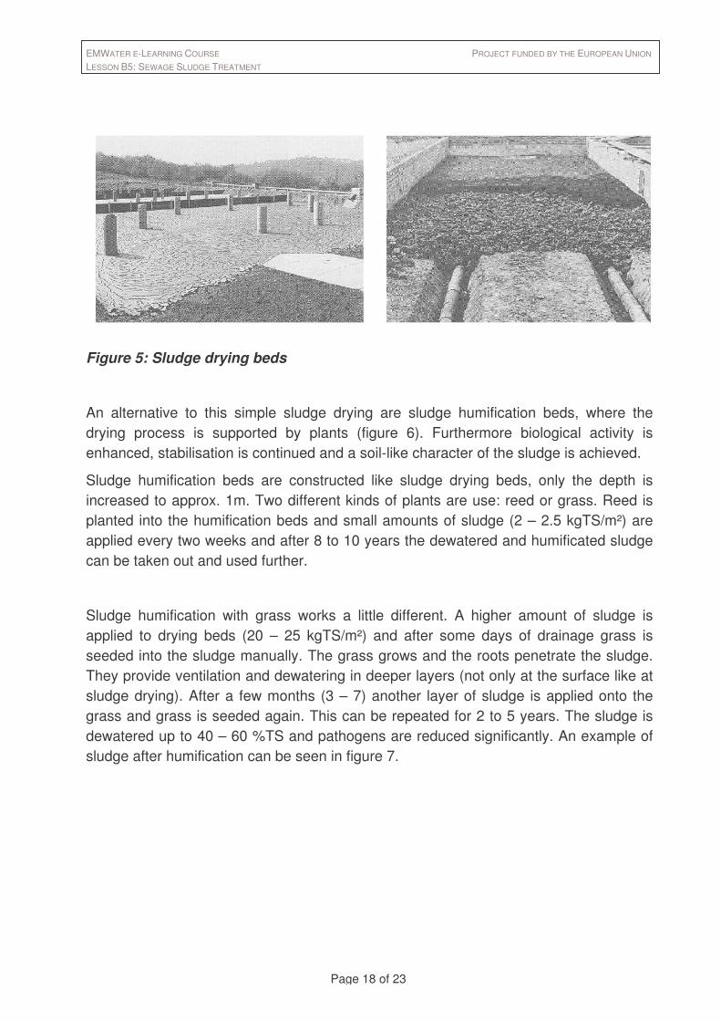
A technique close to nature and very effective is dewatering in drying beds (figure 5). The principal advantages of drying beds are low costs, infrequent attention required, and high solids content in the dried product, especially in arid climates. Disadvantages are the large space required, effects of climatic changes on drying characteristics, labour-intensive sludge removal, insects and potential odours. The most common type are sand drying beds, where the sludge is placed on a bed 200 to 300 mm layer and is allowed to dry. Sludge dewaters by drainage through a drainage system consisting of gravel (200mm), coarse (75mm), fine sand (150 mm) and drainage pipes and by evaporation from the surface exposed to the air. To prevent water from percolating into the soil there has to be a sealing foil.
The drying area is partitioned into individual beds of a convenient size so that one or two beds will be filled in a normal loading cycle (depends on gravity thickener volume). The interior partitions commonly consist of two or three planks, one on top of the other, to a height of approx. 400 to 500 mm. They can be made of concrete, as well. The outer boundaries may be of similar construction or may be earthen embankments or concrete.
Table 4: Typical area requirements for open sludge drying beds (may differ due to extreme climates)
Type of sludge Required area Sludge loading rate
[m²/PE] [kg TS/(m²*a)]
Primary sludge, digested 0.1 120 - 150
Primary and trickling filter humus digested 0.12 – 0.175 90 - 120
primary and secondary sludge digested 0.16 – 0.23 60 - 100
EMWATER E-LEARNING COURSE PROJECT FUNDED BY THE EUROPEAN UNION LESSON B5: SEWAGE SLUDGE TREATMENT
Page 18 of 23
Figure 5: Sludge drying beds
An alternative to this simple sludge drying are sludge humification beds, where the drying process is supported by plants (figure 6). Furthermore biological activity is enhanced, stabilisation is continued and a soil-like character of the sludge is achieved.
Sludge humification beds are constructed like sludge drying beds, only the depth is increased to approx. 1m. Two different kinds of plants are use: reed or grass. Reed is planted into the humification beds and small amounts of sludge (2 – 2.5 kgTS/m²) are applied every two weeks and after 8 to 10 years the dewatered and humificated sludge can be taken out and used further.
Sludge humification with grass works a little different. A higher amount of sludge is applied to drying beds (20 – 25 kgTS/m²) and after some days of drainage grass is seeded into the sludge manually. The grass grows and the roots penetrate the sludge. They provide ventilation and dewatering in deeper layers (not only at the surface like at sludge drying). After a few months (3 – 7) another layer of sludge is applied onto the grass and grass is seeded again. This can be repeated for 2 to 5 years. The sludge is dewatered up to 40 – 60 %TS and pathogens are reduced significantly. An example of sludge after humification can be seen in figure 7.

EMWATER E-LEARNING COURSE PROJECT FUNDED BY THE EUROPEAN UNION LESSON B5: SEWAGE SLUDGE TREATMENT
Page 19 of 23
Figure 6: Sludge humification plant in operation
Figure 7: Sludge after humification
EMWATER E-LEARNING COURSE PROJECT FUNDED BY THE EUROPEAN UNION LESSON B5: SEWAGE SLUDGE TREATMENT
Page 20 of 23
5. Sludge Disposal and Agricultural Utilisation
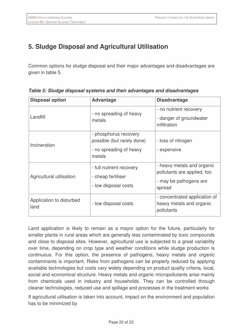
Common options for sludge disposal and their major advantages and disadvantages are given in table 5.
Table 5: Sludge disposal systems and their advantages and disadvantages
Disposal option Advantage Disadvantage
Landfill - no spreading of heavy metals
- no nutrient recovery
- danger of groundwater infiltration
Incineration
- phosphorus recovery possible (but rarely done)
- no spreading of heavy metals
- loss of nitrogen
- expensive
Agricultural utilisation
- full nutrient recovery
- cheap fertiliser
- low disposal costs
- heavy metals and organic pollutants are applied, too
- may be pathogens are spread
Application to disturbed land
- low disposal costs - concentrated application of heavy metals and organic pollutants
Land application is likely to remain as a mayor option for the future, particularly for smaller plants in rural areas which are generally less contaminated by toxic compounds and close to disposal sites. However, agricultural use is subjected to a great variability over time, depending on crop type and weather conditions while sludge production is continuous. For this option, the presence of pathogens, heavy metals and organic contaminants is important. Risks from pathogens can be properly reduced by applying available technologies but costs vary widely depending on product quality criteria, local, social and economical structure. Heavy metals and organic micropollutants arise mainly from chemicals used in industry and households. They can be controlled through cleaner technologies, reduced use and spillage and processes in the treatment works
If agricultural utilisation is taken into account, impact on the environment and population has to be minimized by

EMWATER E-LEARNING COURSE PROJECT FUNDED BY THE EUROPEAN UNION LESSON B5: SEWAGE SLUDGE TREATMENT
Page 21 of 23
• limitation of the applied amount
• further limitation of the applied amount according to the crop’s nutrient demand
• restrictions for sludge rich in heavy-metals
• restricted access to farmland where biosolids have been applied for 30 days
• limitation of application to even areas (< 5 % slope)
• no application close to water bodies
• soil depth to groundwater > 1m
• setback distances to water supply wells (> 150 m) and surface water supply
intake (> 750 m)
• pathogen reducing treatment (thermophilic processes, composting, humification)
• restrictions for the harvesting of crops and turf
As well as for water reuse applications, utilisation of sewage sludge can be a problem of acceptance in the society. For further information about public awareness see lesson E3.
6. Exercises
1. Which pumping systems are suitable for thickened sludge of 8% TS?
2. 100 m³ of secondary sludge (8 kg/m³) are thickened in a gravity thickener to 32 kg/m³. How much is the percentage of TS? How much sludge volume is left?
3. Compute the required surface area and the depth of a round, static thickener: - primary sludge: 200 m³, 2.5% TS withdrawn twice a day for one hour - secondary sludge: 500 m³, 0.6% TS withdrawn continuously

EMWATER E-LEARNING COURSE PROJECT FUNDED BY THE EUROPEAN UNION LESSON B5: SEWAGE SLUDGE TREATMENT
Page 22 of 23
Answers and Solutions
1. A displacement pump has to be chosen. The most suitable would be a progressive cavity pump or a rotary lobe pump.
2. 8 kg/m³ = 8o/oo = 0.8 % 32 kg/m³ = 32o/oo = 3,2 %
resulting volume: 100m³ * 0,8% / 3,2% = 25m³ equals ¼ !
3. Total solids: 200 m³/d * 0.025 * 1000 kg/m³ = 5000 kg/d
500 m³/d * 0.006 * 1000 kg/m³ = 3000 kg/d
(5000 kg/d + 3000 kg/d ) / (200 m³/d +700 m³/d) = 11,4 kg/m³ = 1.14%
→ 700 m³/d, 8000 kg/d, 1.14% TS
- maximum solids load: see Table 3 → 55 kg/(m²*d)
- required surface: 8000 kg / 55 kg/(m²*d) = 145 m², Ø= 13,6 m
- hydraulic overflow rate primary + secondary sludge:
[ (200 m³/d) / (2 h/d) + (500 m³/d) / (24h/d) ] / 145 m³ = 0.83 m/h < 1.0 /h
- hydraulic overflow rate secondary sludge
[ (500 m³/d) / (24h/d) ] / = 0.14 (quite low, adding of process water could be considered)
- depth of compaction zone:
achievable TS-concetration = 5% (table 3), overall 5% * 0,75 = 3.75 %
sludge volume: 8000 kg/d / 37.5 kg/m³ = 213 m³/d
volume of comp. zone: 213 m³/d * 36/24 = 320 m³
depth: 320 m³ / 145 m² = 2.2 m
- overall depth: sedimentation + compaction + scrapers = 1.0 + 2.2 + 0.3 = 3.5 m
EMWATER E-LEARNING COURSE PROJECT FUNDED BY THE EUROPEAN UNION LESSON B5: SEWAGE SLUDGE TREATMENT
Page 23 of 23
7. References and further Information
Ahring, B.K. (1994). Status on science and application of thermophilic anaerobic digestion, Water, Science and Technologie, 30, 241-249
FAO 1992. Wastewater treatment and use in agriculture - FAO irrigation and drainage paper 47, ISBN 92-5-103135-5
Metcalf and Eddy (1991). Wastewater Engineering:Treatment Disposal Reuse.McGraw-
Hill, Inc.
Pabsch, J. Pabsch, H and Purrmann, A. (2003) Sewage sludge humification in a
sequential conversion procedure. GTZ/IWA Conference in Ecosan, Germany
(Downloaded from
http://www.gtz.de/ecosan/download/ecosan-Symposium-Luebeck-session-f.pdf page 39-46)
http://www.sandec.ch/Publications/PublicationsHome.htm
http://europa.eu.int/comm/environment/waste/sludge/index.htm
http://www.unep.or.jp/ietc/Publications/Freshwater/SB_summary/10.asp
Presnitz, W. (2000): The real dirt on sewage sludge. Natural Life magazine, November.
http: // www.life.ca
USEPA 1993 40 CFR Part 503. The standards for the Use and Disposal of Sewage Sludge. Federal Register 58, 9248-9404
Van Lier, J. (1996). Limitations of thermophilic anaerobic wastewater treatment and the consequences for process design. Antonie van Leeuwenhoek, 69, 1-14