leeds street design guide 2009 - leeds.gov.uk street design guide fin… · 1. introduction pg. 1...
TRANSCRIPT
Street Design Guide Leeds Local Development Framework
Supplementary Planning DocumentMain ReportAugust 2009

0113 247 8092
0113 247 8092
0113 247 8092
0113 247 8092
0113 247 8092
If you do not speak English and need help in understanding this document, please phone: (0113) 247 8092 and state the name of your language. We will then put you on hold while we contact an interpreter. This is a free service and we can assist with 100+ languages.
We can also provide this document in audio or Braille on request.
(Bengali):-
(Chinese):-
(Hindi):-
(Punjabi):-
(Urdu):-
This document has been approved as a Supplementary Planning Document (SPD) by Leeds City Council's Executive Board on 26th August 2009.
1. Introduction pg. 1
2. Preparing Development pg. 4 Proposals
3. Design Guidance pg. 7 Key Objectives pg. 7 Street Types pg. 8 Street Type 1 (Connector Streets) pg. 12 Street Type 2 (Local Residential Streets) pg. 15 Street Type 3a (Shared Space Streets) pg. 18 Street Type 3b (Level Surface Streets) pg. 22 Street Type 4 (Home Zones) pg. 24 Speed Restraint pg. 31 Vertical Alignment pg. 35 Junctions and Visibility pg. 36 Pedestrian Movement pg. 43 Cycling pg. 45 Designing for Disabled People pg. 49 Car Parking pg. 50 Servicing, Vehicle Tracking and Turning Spaces pg. 59 Emergency Access pg. 62 Landscape Considerations Within the Highway pg. 63 Public Utilities pg. 64 Drainage pg. 67 Highway Structures pg. 68 Public Transport pg. 68 Other Requirements pg. 69
4. Materials and Construction pg. 71 General Approach pg. 71 Specification pg. 72 Carriageways pg. 72 Footways, Kerbs and Crossings pg. 75 Drainage pg. 76 Conservation Areas pg. 76
Index pg. 77
Contents
1 2
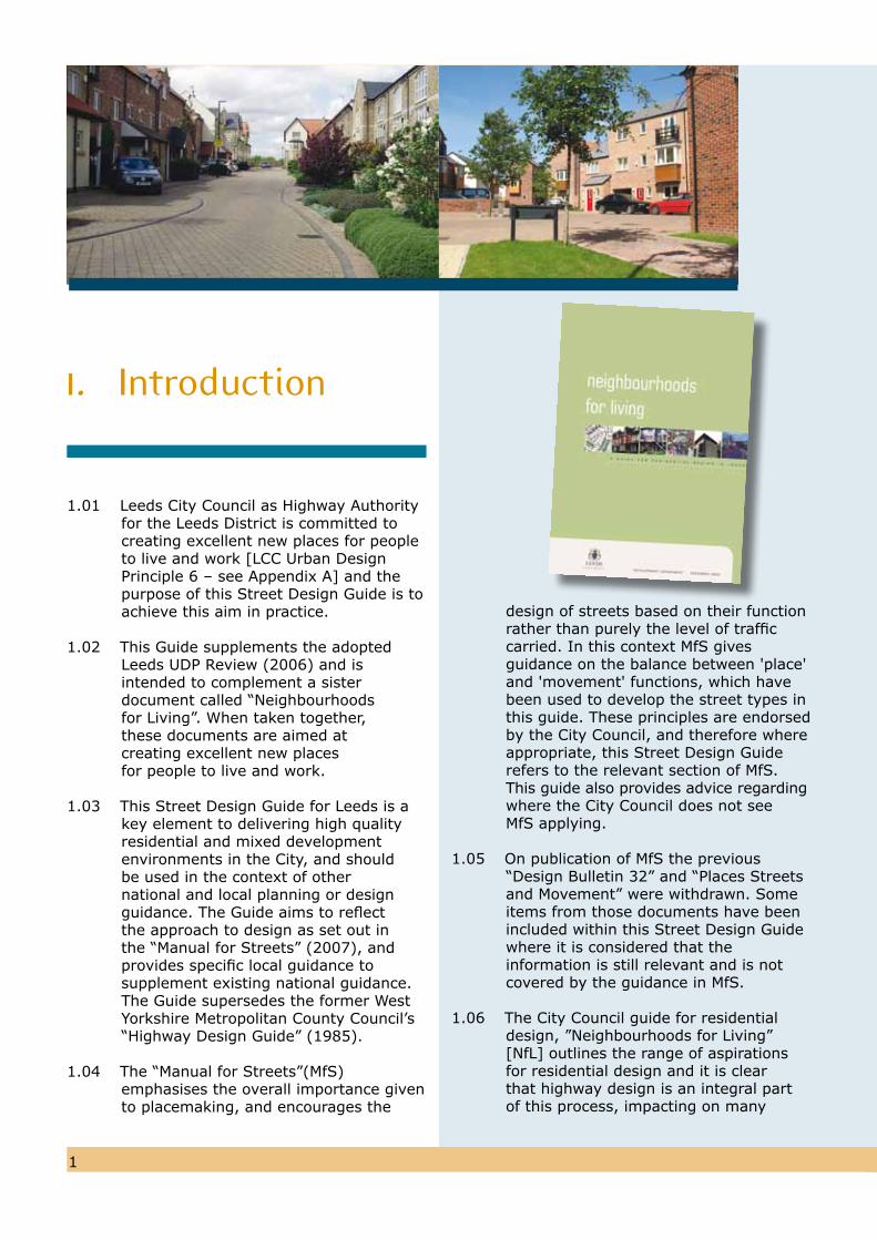
1.01 Leeds City Council as Highway Authority for the Leeds District is committed to creating excellent new places for people to live and work [LCC Urban Design Principle 6 – see Appendix A] and the purpose of this Street Design Guide is toachieve this aim in practice.
1.02 This Guide supplements the adoptedLeeds UDP Review (2006) and is intended to complement a sister document called “Neighbourhoods for Living”. When taken together, these documents are aimed at creating excellent new places for people to live and work.
1.03 This Street Design Guide for Leeds is akey element to delivering high quality residential and mixed development environments in the City, and should be used in the context of other national and local planning or design guidance. The Guide aims to reflect the approach to design as set out in the “Manual for Streets” (2007), and provides specific local guidance to supplement existing national guidance. The Guide supersedes the former West Yorkshire Metropolitan County Council’s “Highway Design Guide” (1985).
1.04 The “Manual for Streets”(MfS) emphasises the overall importance given to placemaking, and encourages the
design of streets based on their functionrather than purely the level of traffic carried. In this context MfS gives guidance on the balance between 'place'and 'movement' functions, which havebeen used to develop the street types in this guide. These principles are endorsed by the City Council, and therefore whereappropriate, this Street Design Guide refers to the relevant section of MfS.This guide also provides advice regardingwhere the City Council does not seeMfS applying.
1.05 On publication of MfS the previous “Design Bulletin 32” and “Places Streets and Movement” were withdrawn. Some items from those documents have beenincluded within this Street Design Guidewhere it is considered that the information is still relevant and is not covered by the guidance in MfS.
1.06 The City Council guide for residential design, ”Neighbourhoods for Living” [NfL] outlines the range of aspirations for residential design and it is clear that highway design is an integral part of this process, impacting on many
1. Introduction
1 2
of the considerations. What is also clear is that the design of good quality streets will go a long way towards achieving the overall aspirations.
1.07 The guide is intended for use by developers, design teams and others, and seeks to stimulate innovative designs that are appropriate for the context, character and location of a site and can be used safely by the travelling public. Designs will be encouraged to incorporate quality approved sustainable materials that are visually attractive, require minimum maintenance, and are in keeping with the specific local character of the area.
1.08 The guide covers the design of the ‘highway’ in its broadest sense, namely the public space between private dwellings or plots which facilitates all public activity, including, but not exclusively, the circulation and storage of motorised traffic. To this end the guide encourages designers to consider ‘streets’, not just ‘roads’, and also all the other components that make up the public realm (e.g. signs, cabinets, lighting, landscape, etc).
1.09 Achieving sustainable developments is crucial if the City Council is to meet its social, economic and environment objectives. These relate to sustainability in its widest sense, not only transport accessibility, so that sustainable
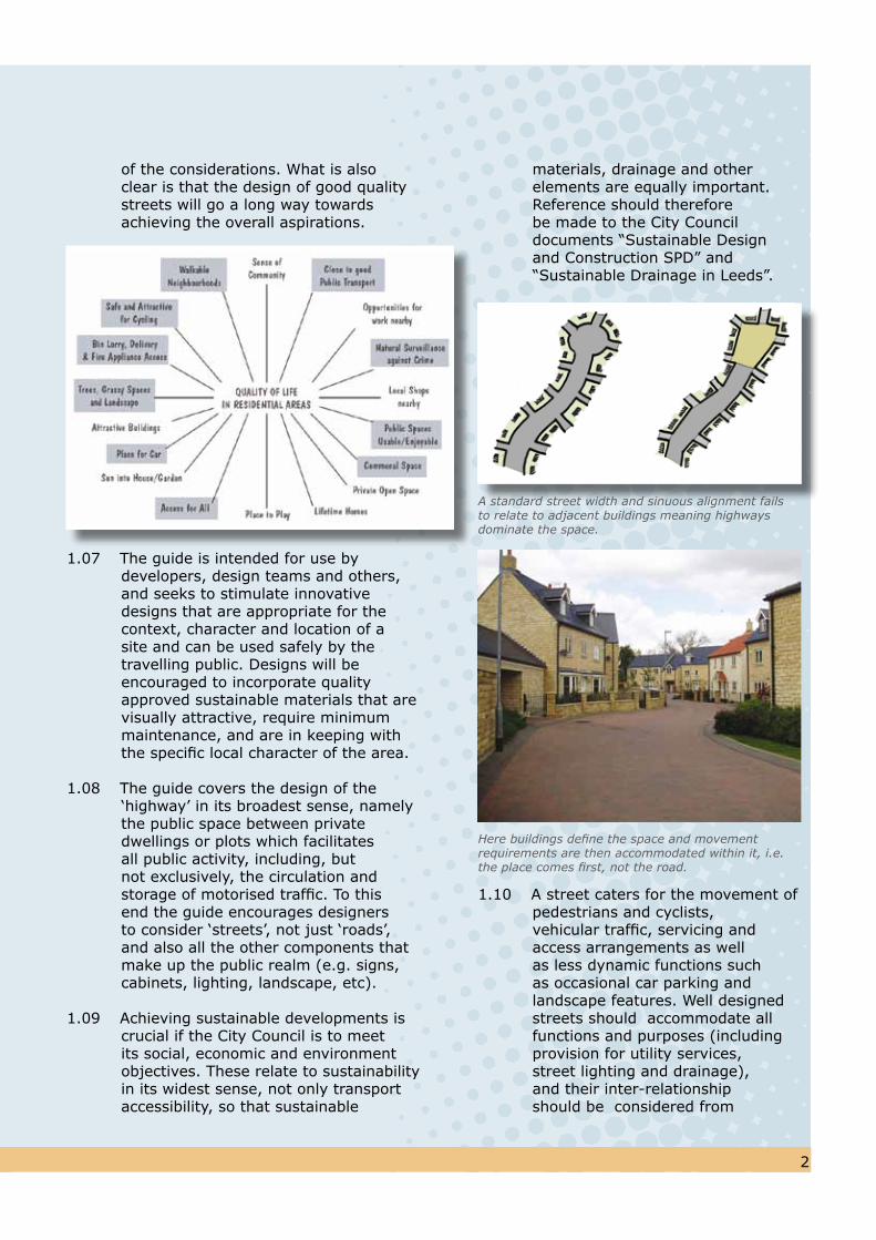
materials, drainage and other elements are equally important. Reference should therefore be made to the City Council documents “Sustainable Design and Construction SPD” and “Sustainable Drainage in Leeds”.
1.10 A street caters for the movement of pedestrians and cyclists, vehicular traffic, servicing and access arrangements as well as less dynamic functions such as occasional car parking and landscape features. Well designed streets should accommodate all functions and purposes (including provision for utility services, street lighting and drainage), and their inter-relationship should be considered from
A standard street width and sinuous alignment failsto relate to adjacent buildings meaning highwaysdominate the space.
Here buildings define the space and movementrequirements are then accommodated within it, i.e.the place comes first, not the road.
3
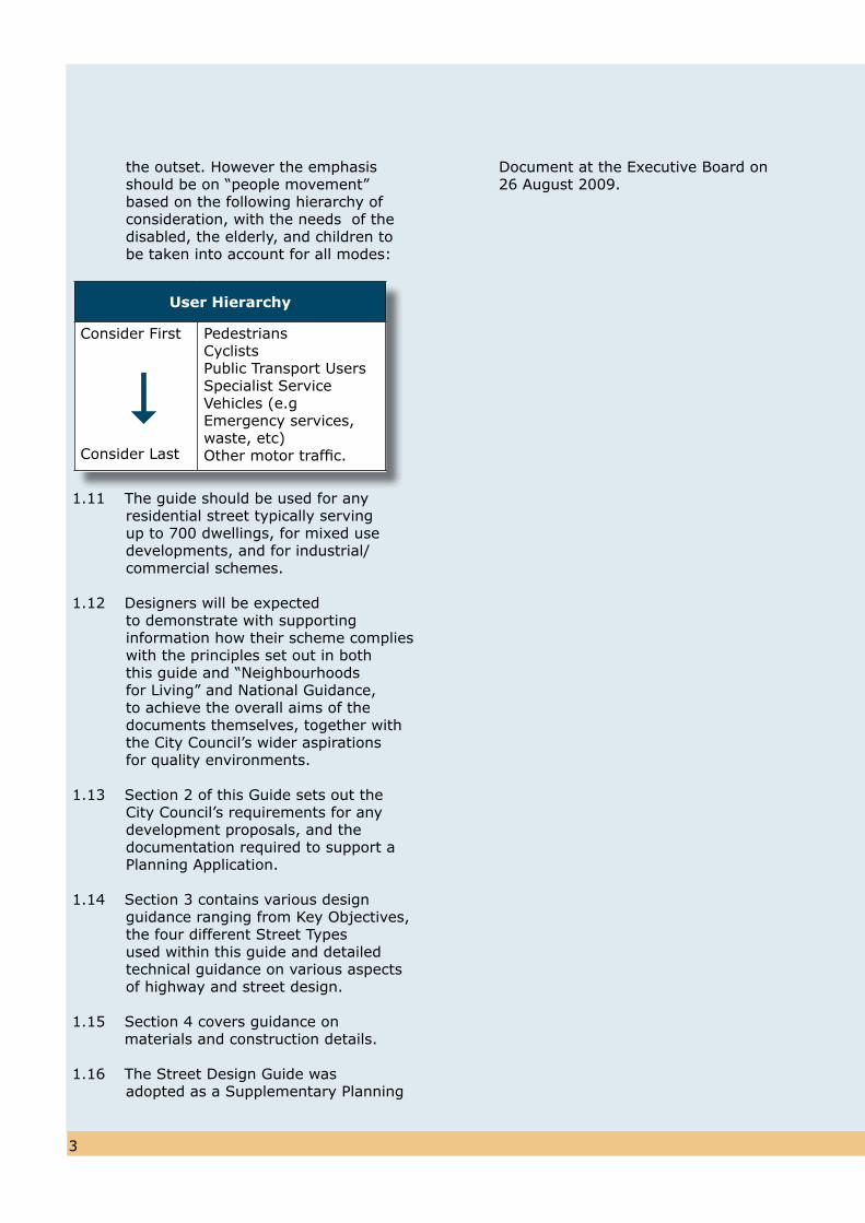
the outset. However the emphasis should be on “people movement” based on the following hierarchy of consideration, with the needs of the disabled, the elderly, and children to be taken into account for all modes:
1.11 The guide should be used for any residential street typically serving up to 700 dwellings, for mixed use developments, and for industrial/commercial schemes.
1.12 Designers will be expected to demonstrate with supporting information how their scheme complies with the principles set out in both this guide and “Neighbourhoods for Living” and National Guidance, to achieve the overall aims of the documents themselves, together with the City Council’s wider aspirations for quality environments.
1.13 Section 2 of this Guide sets out theCity Council’s requirements for anydevelopment proposals, and thedocumentation required to support aPlanning Application.
1.14 Section 3 contains various design guidance ranging from Key Objectives, the four different Street Types used within this guide and detailed technical guidance on various aspects of highway and street design.
1.15 Section 4 covers guidance on materials and construction details.
1.16 The Street Design Guide wasadopted as a Supplementary Planning
User Hierarchy
Consider First
Consider Last
Pedestrians Cyclists Public Transport Users Specialist Service Vehicles (e.g Emergency services, waste, etc)Other motor traffic.
Document at the Executive Board on26 August 2009.
3 4
2.01 The preparation of successful high quality development proposals requires the design team and Council Officers to work together and also to involve the wider community [LCC Urban Design Principles 2 and 3 – see Appendix A]. This multidisciplinary approach needs to involve Architects, Planners, Engineers, Urban Designers, Landscape Architects and other stakeholders.
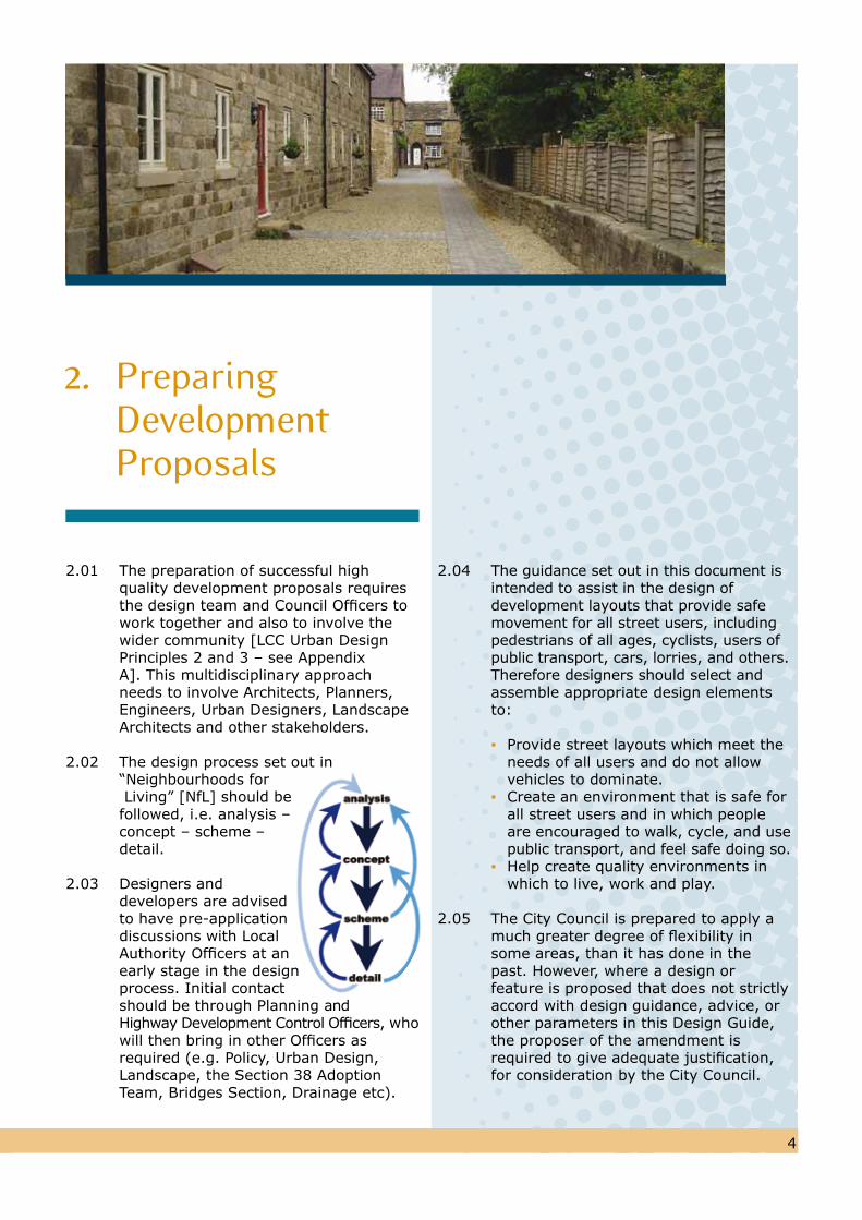
2.02 The design process set out in “Neighbourhoods for Living” [NfL] should be followed, i.e. analysis – concept – scheme – detail.
2.03 Designers and developers are advised to have pre-application discussions with Local Authority Officers at an early stage in the design process. Initial contact should be through Planning and Highway Development Control Officers, who will then bring in other Officers as required (e.g. Policy, Urban Design, Landscape, the Section 38 Adoption Team, Bridges Section, Drainage etc).
2.04 The guidance set out in this document is intended to assist in the design of development layouts that provide safemovement for all street users, includingpedestrians of all ages, cyclists, users ofpublic transport, cars, lorries, and others.
Therefore designers should select and assemble appropriate design elements to:
▪ Provide street layouts which meet the needs of all users and do not allow vehicles to dominate.▪ Create an environment that is safe for all street users and in which people are encouraged to walk, cycle, and use public transport, and feel safe doing so.▪ Help create quality environments in which to live, work and play.
2.05 The City Council is prepared to apply amuch greater degree of flexibility in some areas, than it has done in the past. However, where a design or feature is proposed that does not strictly accord with design guidance, advice, or other parameters in this Design Guide, the proposer of the amendment is required to give adequate justification, for consideration by the City Council.
2. Preparing Development Proposals
5
2.06 The amendment will only be allowed if it fulfils all of the following requirements:
▪ Does not result in adverse or differential effects on selected groups, primarily disabled people (mobility impaired, blind/partially sighted, hearing impaired) children, and elderly people.▪ Does not diminish the convenience and suitability of facilities for pedestrians, cyclists and public transport users.▪ Does not diminish the sustainability of the design under any of the sustainability aspects highlighted in the document.▪ Does not contravene UDP policy T2 (namely that “it will not create or materially add to problems of safety, environment or efficiency on the highway network”).▪ Does not lead to a reduction in quality of public realm, or the durability of infrastructure.▪ Does not lead to a deterioration in any other sustainability consideration.▪ Does not result in a lower standard of road safety.
2.07 There is a principle of ‘no trade-offs’ inassessing amendments. That is, a positive contribution on one factor can not be traded-off against a negative effect elsewhere. Amendments whichincrease sustainability or the design’s user friendliness for selected groups of people, without detriment to others,will be viewed positively. Amendments which are proposed primarily for reasons of minimising costs will only beconsidered if all of the aboverequirements are satisfied. Amendmentswhich are proposed primarily to overcome physical site constraints orlegal restrictions will be considered ontheir merits.
2.08 It is essential that this guide is used in conjunction with “Neighbourhoods forLiving”, and recommendations on the appropriate parts of that document to refer to are included in the relevant sections of this Street Design Guide [as NfL Principle …….]. In City Centre
areas, the Council’s SPG 14, “Leeds City Centre Urban Design Strategy” should also be referred to.
2.09 Development proposals should be accompanied by various supporting documentation as required by Leeds City Council’s Planning Department. Certain highway and transport reports will / may be required as follows:
i) Design and Access Statement - This will set out the main placemaking, design and sustainability elements of the scheme, and should demonstrate how it complies with the objectives and requirements of this guide and “Neighbourhoods for Living”. Areas to be offered for adoption should be clearly identified. Such a Design Statement will be required for all developments, although clearly a smaller scheme will require a briefer statement than a large development. Advice on the preparation of these statements has beenproduced by CABE. ii) Transport Assessment - Developments over 80 dwellings (or others in the DfT’s “Guidance on Transport Assessments”) will normally require the preparation of a full Transport Assessment (TA). The scope of the TA should be agreed in advance with the Local Authority, and should assess both traffic impact and transport sustainability, including an assessment of how well a scheme addresses the needs of pedestrians of all ages, cyclists and non- motorised users. iii) Transport Statement - Developments
of between 50 and 80 dwellings (or others in the DfT’s guidance) will normally require an abbreviated form of a TA, addressing certain limited issues which are relevant to the particular scheme. The scope of the Transport Statement should be agreed in advance with the Local Authority, and should cover accessibility as well as impact.
iv) Travel Plan - Certain developments, as identified by the City Council, will require the provision of a Travel Plan,
6

5 6
to specify the measures that will be taken to encourage the use of non-car modes of transport. Any Travel Plan will need to be approved prior to Planning Permission being granted. Guidance on the preparation of Travel Plans is contained in the draft SPD Travel Plans.
v) Quality Audit - All developments require the provision of an audit of the quality of the proposed new streets. This will include a specific safety audit (as described below), and should also consider issues of buildability and maintenance, e.g. resurfacing, cleansing, preventing litter traps, specifying available materials, etc.
vi) Safety Audit - A City Council approved organisation shall undertake an independent Stage One and/or Two Safety Audit.These look at highway works from the perspective of the end user, andspecifically aim to identify any safety issues that may need to be addressed. The timing and need for a Safety Audit should be discussed with the Local Authority at an early stage. All layouts which meet the requirements for adoption will normally require a safety audit. AnySafety Audit and exception report will need to be approved prior to planning permission being granted. Where relevant, Safety Audits shouldinclude an assessment of the likelylevel of risk. Safety audits should beconsidered alongside the QualityAudit.
8
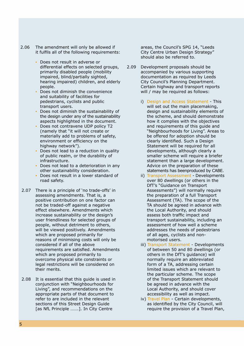
Key Objectives
3.01 In making good places, it is vital that highways and transportation matters are considered at the same time as other aspects of the design of the development. A co-ordinated approach to design should therefore meet the following key objectives, and the Design Statement for any scheme should demonstrate how these objectives have been met:
▪ Deliver high quality developments that relate the site to its particular neighbourhood [NfL Principle 1] ▪ Design streets as spaces for people (including the disabled), whilst still accommodating all necessary types of street users [NfL Principles 27 and 29] ▪ Link the development into the external network of facilities [NfL Principles 5 and 14] ▪ Identify intrinsic landscape characteristics of the site and its setting, and retain/enhance existing features e.g. trees [NfL Principle 55] ▪ Provide safe, convenient, direct and easy access to everyday facilities on foot and cycle [NfL Principle 13] ▪ Maximise choice for people to be able to make journeys by non-car modes [NfL Principle 19] ▪ Provide convenient and secure cycle parking [NfL Principle 75]
▪ Regulate vehicle speeds to the appropriate design speed for the street [NfL Principle 34] ▪ Provide car parking areas that are usable, safe and secure, and can be managed efficiently without dominating the street scene [NfL Principles 76 and 77] ▪ Use simple, appropriate, well-detailed high quality materials that form a cohesive family of components requiring minimal, economical maintenance (NfL Principles 35 and 37] ▪ Avoid the potential for “bad neighbour” problems ▪ Design for community safety [NfL Principle 43].
7
3. Design Guidance
8
Street Types
General Approach
3.02 To achieve the key objectives, plus high quality and varied residential spaces, it is necessary to allow a greater degree of flexibility in highway design standards than has previously been allowed, with due regard to current statutory regulations, whilst still maintaining levels of road safety, and the other requirements set out in paragraph 2.06
3.03 Guidance that contains too many unnecessary rules and restrictions can inhibit innovation, preventing schemes from reflecting local character and distinctiveness.
3.04 However, a more flexible approach alsoplaces greater responsibility on the Design Team to demonstrate that theproposals will operate safely and satisfactorily, are maintainable andsustainable, and to justify the design choices that have been made.
3.05 This Street Design Guide covers the following situations:
a) Residential streets serving up to approximately 700 dwellingsb) Industrial or commercial developments serving up to 20 hectares of industrial landc) Mixed use schemes generating up to approximately 455 two-way peak hour movements, which is the traffic flow likely to be generated by a development of 700 dwellingsd) Private (non-adopted) streets or drives
3.06 Any road that is intended to serve morethan 700 dwellings should be discussedwith the City Council, and may need tobe designed in accordance with the“Design Manual for Roads and Bridges”(published by the Department forTransport), as it is in effect not aresidential street. However the principlesof the design guidance set out in thisStreet Design Guide will still be applicable, as the function of the street
should still be a key consideration in thedesign process.
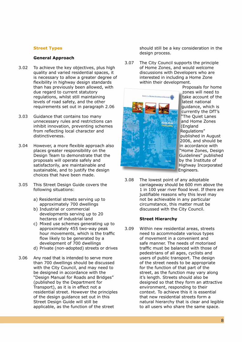
3.07 The City Council supports the principleof Home Zones, and would welcomediscussions with Developers who areinterested in including a Home Zonewithin their development.
Proposals for home zones will need to take account of thelatest nationalguidance, which is currently the DfT’s“The Quiet Lanes and Home Zones(England Regulations” published in August2006, and should bein accordance with “Home Zones, Design Guidelines” published by the Institute of Highway Incorporated Engineers.
3.08 The lowest point of any adoptable carriageway should be 600 mm above the 1 in 100 year river flood level. If there are justifiable reasons why this level may not be achievable in any particular
circumstance, this matter must bediscussed with the City Council.
Street Hierarchy
3.09 Within new residential areas, streets need to accommodate various types of movement in a convenient and safe manner. The needs of motorised traffic must be balanced with those of pedestrians of all ages, cyclists and users of public transport. The design of the street needs to be appropriate for the function of that part of the street, as the function may vary along it’s length. Streets should also be designed so that they form an attractive environment, responding to their context. To achieve this it is essential that new residential streets form a natural hierarchy that is clear and legible to all users who share the same space.
7
109
3.10 This hierarchy should provide an understandable transition from the external distributor roads where motor vehicular space requirements may be more dominant, to residential streets (covered by this Design Guide) where the needs of pedestrians and other non-car users are of greater importance.
3.11 Further guidance on the setting up of a street hierarchy and network is given in the “Movement” section of “Neighbourhoods for Living” [NfL].
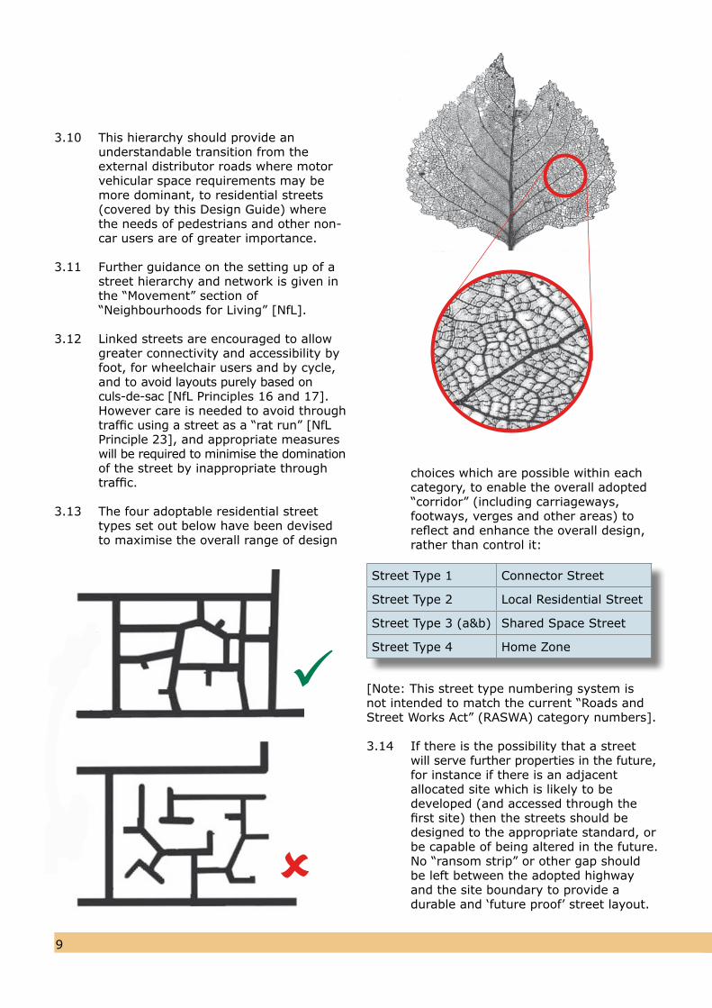
3.12 Linked streets are encouraged to allow greater connectivity and accessibility byfoot, for wheelchair users and by cycle,and to avoid layouts purely based onculs-de-sac [NfL Principles 16 and 17].However care is needed to avoid throughtraffic using a street as a “rat run” [NfLPrinciple 23], and appropriate measureswill be required to minimise the dominationof the street by inappropriate throughtraffic.
3.13 The four adoptable residential street types set out below have been devised to maximise the overall range of design
choices which are possible within each category, to enable the overall adopted “corridor” (including carriageways, footways, verges and other areas) toreflect and enhance the overall design,rather than control it:
[Note: This street type numbering system is not intended to match the current “Roads and Street Works Act” (RASWA) category numbers].
3.14 If there is the possibility that a street will serve further properties in the future,for instance if there is an adjacent allocated site which is likely to be developed (and accessed through the first site) then the streets should be designed to the appropriate standard, or be capable of being altered in the future. No “ransom strip” or other gap should be left between the adopted highway and the site boundary to provide a durable and ‘future proof’ street layout.
Street Type 1 Connector Street
Street Type 2 Local Residential Street
Street Type 3 (a&b) Shared Space Street
Street Type 4 Home Zone
109
The Site
Rail Station
Park
Park
Gree
n Co
rrid
or
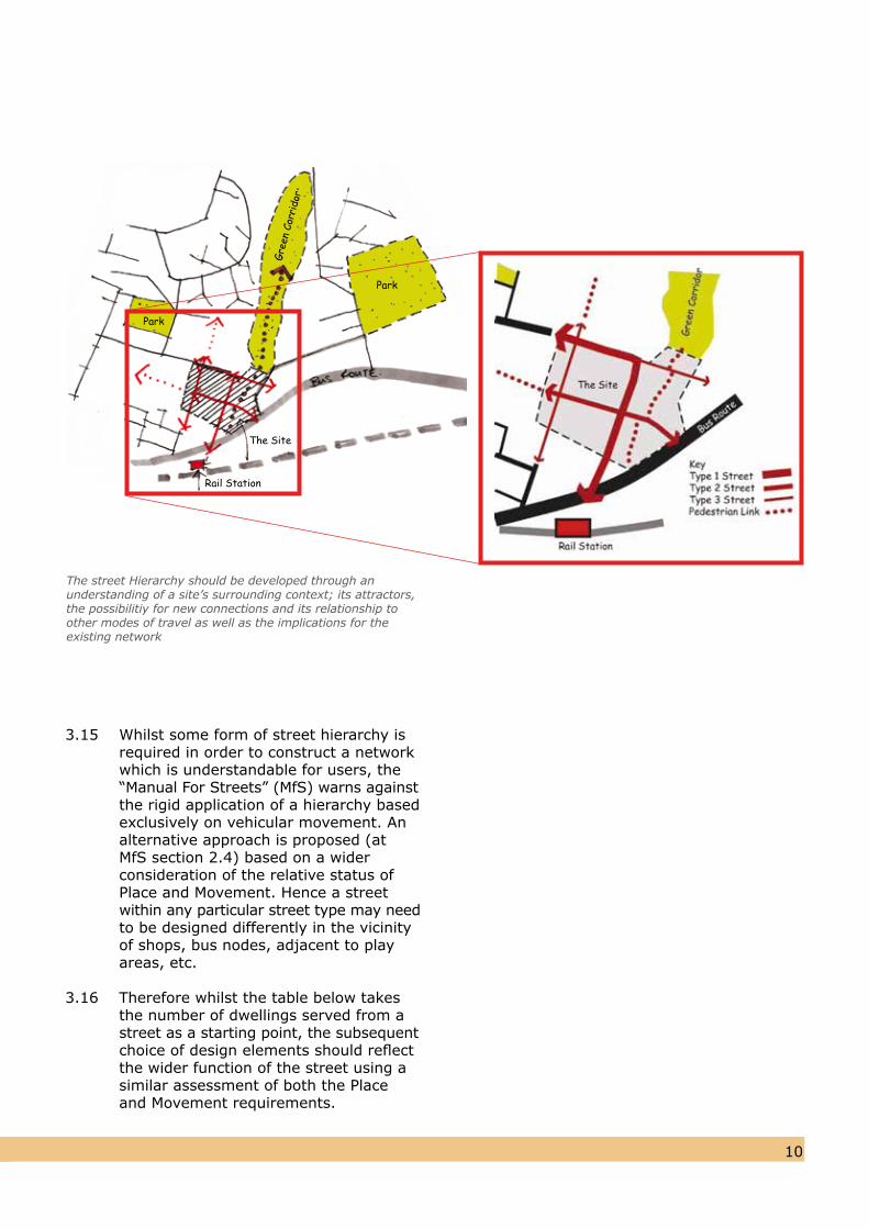
The street Hierarchy should be developed through anunderstanding of a site’s surrounding context; its attractors,the possibilitiy for new connections and its relationship toother modes of travel as well as the implications for theexisting network
3.15 Whilst some form of street hierarchy isrequired in order to construct a networkwhich is understandable for users, the“Manual For Streets” (MfS) warns againstthe rigid application of a hierarchy basedexclusively on vehicular movement. Analternative approach is proposed (atMfS section 2.4) based on a wider consideration of the relative status ofPlace and Movement. Hence a streetwithin any particular street type may needto be designed differently in the vicinityof shops, bus nodes, adjacent to playareas, etc.
3.16 Therefore whilst the table below takesthe number of dwellings served from astreet as a starting point, the subsequentchoice of design elements should reflectthe wider function of the street using asimilar assessment of both the Place and Movement requirements.
1211
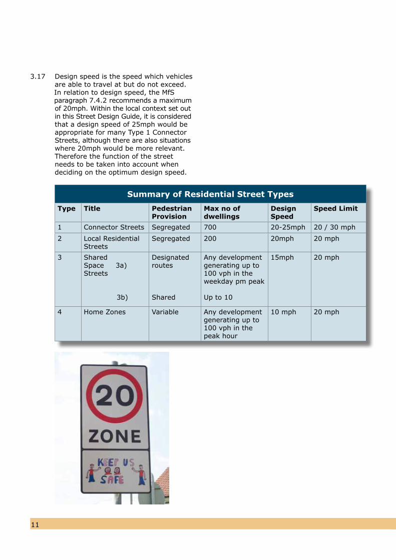
3.17 Design speed is the speed which vehiclesare able to travel at but do not exceed.
In relation to design speed, the MfS paragraph 7.4.2 recommends a maximum
of 20mph. Within the local context set outin this Street Design Guide, it is consideredthat a design speed of 25mph would beappropriate for many Type 1 ConnectorStreets, although there are also situationswhere 20mph would be more relevant. Therefore the function of the street needs to be taken into account when deciding on the optimum design speed.
Summary of Residential Street Types
Type Title Pedestrian Provision
Max no of dwellings
Design Speed
Speed Limit
1 Connector Streets Segregated 700 20-25mph 20 / 30 mph
2 Local Residential Streets
Segregated 200 20mph 20 mph
3 SharedSpace 3a) Streets
3b)
Designated routes
Shared
Any development generating up to 100 vph in the weekday pm peak
Up to 10
15mph 20 mph
4 Home Zones Variable Any development generating up to100 vph in thepeak hour
10 mph 20 mph
1211
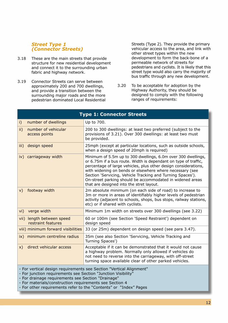
Type 1: Connector Streets
i) number of dwellings Up to 700.
ii) number of vehicular 0 access points
200 to 300 dwellings: at least two preferred (subject to theprovisions of 3.21). Over 300 dwellings: at least two mustbe provided.
iii) design speed 25mph (except at particular locations, such as outside schools,when a design speed of 20mph is required)
iv) carriageway width Minimum of 5.5m up to 300 dwellings, 6.0m over 300 dwellings,or 6.75m if a bus route. Width is dependant on type of traffic,percentage of large vehicles, plus other design considerations,with widening on bends or elsewhere where necessary (seeSection 'Servicing, Vehicle Tracking and Turning Spaces'). On-street parking should be accommodated in widened areasthat are designed into the stret layout.
v) footway width 2m absolute minimum (on each side of road) to increase to3m or more in areas of identifiably higher levels of pedestrianactivity (adjacent to schools, shops, bus stops, railway stations,etc) or if shared with cyclists.
vi) verge width Minimum 1m width on streets over 300 dwellings (see 3.22)
vii) length between speed 0 restraint features
60 or 100m (see Section 'Speed Restraint') dependent ondesign speed
viii) minimum forward visibilities 33 (or 25m) dependent on design speed (see para 3.47).
ix) minimum centreline radius 35m (see also Section 'Servicing, Vehicle Tracking andTurning Spaces')
x) direct vehicular access Acceptable if it can be demonstrated that it would not cause a highway problem. Normally only allowed if vehicles do not need to reverse into the carriageway, with off-street turning space available clear of other parked vehicles.
- For vertical design requirements see Section "Vertical Alignment"- For junction requirements see Section "Junction Visibility"- For drainage requirements see Section "Drainage"- For materials/construction requirements see Section 4- For other requirements refer to the “Contents” or “Index” Pages
Street Type 1 (Connector Streets)
3.18 These are the main streets that provide structure for new residential development and connect it to the surrounding urban fabric and highway network. 3.19 Connector Streets can serve between approximately 200 and 700 dwellings, and provide a transition between the surrounding major roads and the more pedestrian dominated Local Residential
Streets (Type 2). They provide the primary vehicular access to the area, and link with other street types within the new development to form the back-bone of a permeable network of streets for pedestrians and cyclists. It is likely that this street type would also carry the majority of bus traffic through any new development.
3.20 To be acceptable for adoption by the Highway Authority, they should be designed to comply with the following ranges of requirements:
1413
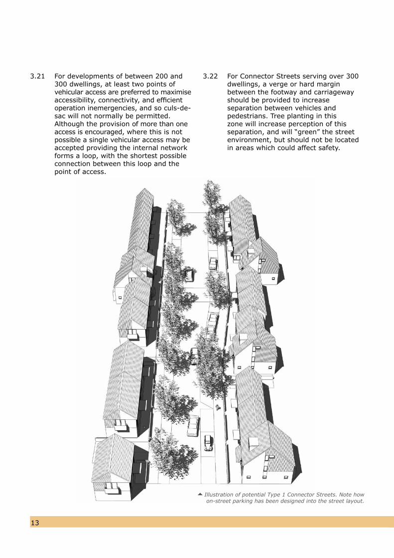
Illustration of potential Type 1 Connector Streets. Note howon-street parking has been designed into the street layout.
3.21 For developments of between 200 and300 dwellings, at least two points ofvehicular access are preferred to maximiseaccessibility, connectivity, and efficient operation inemergencies, and so culs-de-sac will not normally be permitted. Although the provision of more than oneaccess is encouraged, where this is notpossible a single vehicular access may beaccepted providing the internal networkforms a loop, with the shortest possible connection between this loop and thepoint of access.
3.22 For Connector Streets serving over 300dwellings, a verge or hard margin between the footway and carriageway should be provided to increase separation between vehicles and pedestrians. Tree planting in this zone will increase perception of this separation, and will “green” the street environment, but should not be located in areas which could affect safety.
1413
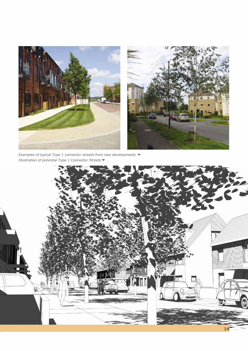
Illustration of potential Type 1 Connector StreetsExamples of typical Type 1 connector streets from new developments
1615
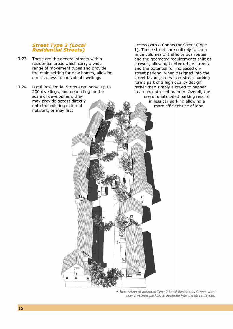
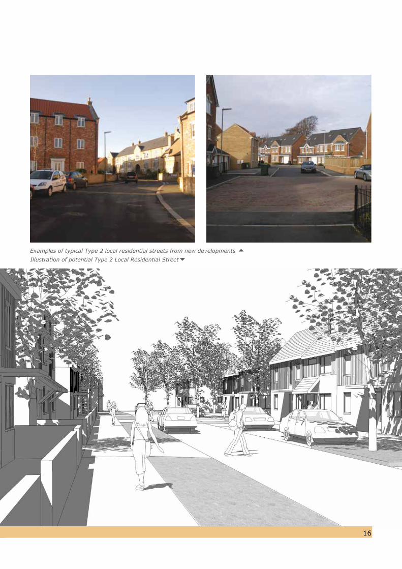
Illustration of potential Type 2 Local Residential Street. Note how on-street parking is designed into the street layout.
Street Type 2 (Local Residential Streets)
3.23 These are the general streets withinresidential areas which carry a wide range of movement types and provide the main setting for new homes, allowing direct access to individual dwellings.
3.24 Local Residential Streets can serve up to200 dwellings, and depending on thescale of development they may provide access directly onto the existing external network, or may first
access onto a Connector Street (Type 1). These streets are unlikely to carry large volumes of traffic or bus routes and the geometry requirements shift as a result, allowing tighter urban streets and the potential for increased on-street parking, when designed into the street layout, so that on-street parking forms part of a high quality design rather than simply allowed to happen in an uncontrolled manner. Overall, the
use of unallocated parking results in less car parking allowing a
more efficient use of land.
1615
Examples of typical Type 2 local residential streets from new developments Illustration of potential Type 2 Local Residential Street
1817
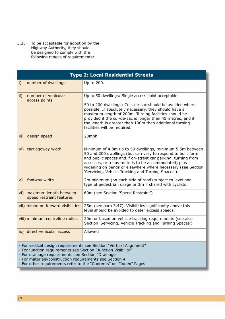
Type 2: Local Residential Streets
i) number of dwellings Up to 200.
ii) number of vehicular 0 access points
Up to 50 dwellings: Single access point acceptable
50 to 200 dwellings: Culs-de-sac should be avoided wherepossible. If absolutely necessary, they should have amaximum length of 200m. Turning facilities should beprovided if the cul-de-sac is longer than 45 metres, and ifthe length is greater than 100m then additional turningfacilities will be required.
iii) design speed 20mph
iv) carriageway width Minimum of 4.8m up to 50 dwellings, minimum 5.5m between50 and 200 dwellings (but can vary to respond to built formand public spaces and if on-street car parking, turning fromaccesses, or a bus route is to be accommodated) pluswidening on bends or elsewhere where necessary (see Section'Servicing, Vehicle Tracking and Turning Spaces').
v) footway width 2m minimum (on each side of road) subject to level and type of pedestrian usage or 3m if shared with cyclists.
vi) maximum length between speed restraint features
60m (see Section 'Speed Restraint')
vii) minimum forward visibilities 25m (see para 3.47). Visibilities significantly above this level should be avoided to deter excess speeds.
viii) minimum centreline radius 20m or based on vehicle tracking requirements (see alsoSection 'Servicing, Vehicle Tracking and Turning Spaces')
ix) direct vehicular access Allowed
- For vertical design requirements see Section "Vertical Alignment"- For junction requirements see Section "Junction Visibility"- For drainage requirements see Section "Drainage"- For materials/construction requirements see Section 4- For other requirements refer to the “Contents” or “Index” Pages
3.25 To be acceptable for adoption by theHighway Authority, they should be designed to comply with the following ranges of requirements:
1817
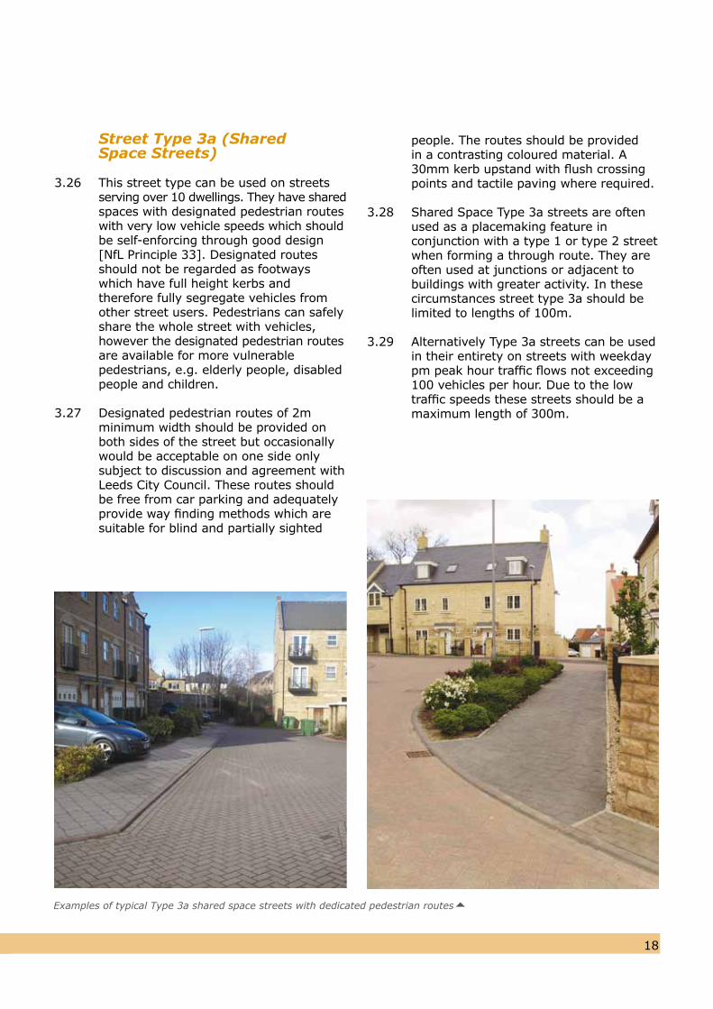
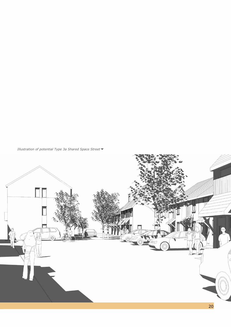
Street Type 3a (Shared Space Streets)
3.26 This street type can be used on streets serving over 10 dwellings. They have sharedspaces with designated pedestrian routeswith very low vehicle speeds which shouldbe self-enforcing through good design[NfL Principle 33]. Designated routes should not be regarded as footways which have full height kerbs and therefore fully segregate vehicles fromother street users. Pedestrians can safelyshare the whole street with vehicles,however the designated pedestrian routesare available for more vulnerablepedestrians, e.g. elderly people, disabledpeople and children.
3.27 Designated pedestrian routes of 2m minimum width should be provided on both sides of the street but occasionally would be acceptable on one side only subject to discussion and agreement with Leeds City Council. These routes should be free from car parking and adequately provide way finding methods which are suitable for blind and partially sighted
people. The routes should be provided in a contrasting coloured material. A 30mm kerb upstand with flush crossing points and tactile paving where required.
3.28 Shared Space Type 3a streets are often used as a placemaking feature in conjunction with a type 1 or type 2 street when forming a through route. They areoften used at junctions or adjacent tobuildings with greater activity. In these circumstances street type 3a should belimited to lengths of 100m.
3.29 Alternatively Type 3a streets can be used in their entirety on streets with weekdaypm peak hour traffic flows not exceeding100 vehicles per hour. Due to the lowtraffic speeds these streets should be amaximum length of 300m.
Examples of typical Type 3a shared space streets with dedicated pedestrian routes
2019
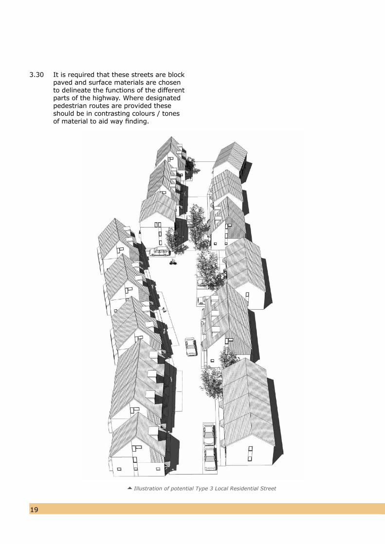
Illustration of potential Type 3 Local Residential Street
3.30 It is required that these streets are blockpaved and surface materials are chosen to delineate the functions of the different parts of the highway. Where designated pedestrian routes are provided these should be in contrasting colours / tonesof material to aid way finding.
2019
Illustration of potential Type 3a Shared Space Street
2221
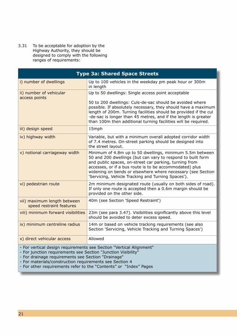
3.31 To be acceptable for adoption by theHighway Authority, they should bedesigned to comply with the followingranges of requirements:
Type 3a: Shared Space Streets
i) number of dwellings Up to 100 vehicles in the weekday pm peak hour or 300min length
ii) number of vehicular access points
Up to 50 dwellings: Single access point acceptable
50 to 200 dwellings: Culs-de-sac should be avoided wherepossible. If absolutely necessary, they should have a maximumlength of 200m. Turning facilities should be provided if the cul-de-sac is longer than 45 metres, and if the length is greaterthan 100m then additional turning facilities will be required.
iii) design speed 15mph
iv) highway width Variable, but with a minimum overall adopted corridor widthof 7.4 metres. On-street parking should be designed intothe street layout.
v) notional carriageway width Minimum of 4.8m up to 50 dwellings, minimum 5.5m between50 and 200 dwellings (but can vary to respond to built formand public spaces, on-street car parking, turning fromaccesses, or if a bus route is to be accommodated) pluswidening on bends or elsewhere where necessary (see Section'Servicing, Vehicle Tracking and Turning Spaces').
vi) pedestrian route 2m minimum designated route (usually on both sides of road).If only one route is accepted then a 0.6m margin should beprovided on the other side.
vii) maximum length between speed restraint features
40m (see Section 'Speed Restraint')
viii) minimum forward visibilities 23m (see para 3.47). Visibilities significantly above this levelshould be avoided to deter excess speed.
ix) minimum centreline radius 14m or based on vehicle tracking requirements (see alsoSection 'Servicing, Vehicle Tracking and Turning Spaces')
x) direct vehicular access Allowed
- For vertical design requirements see Section "Vertical Alignment"- For junction requirements see Section "Junction Visibility"- For drainage requirements see Section "Drainage"- For materials/construction requirements see Section 4- For other requirements refer to the “Contents” or “Index” Pages
2221
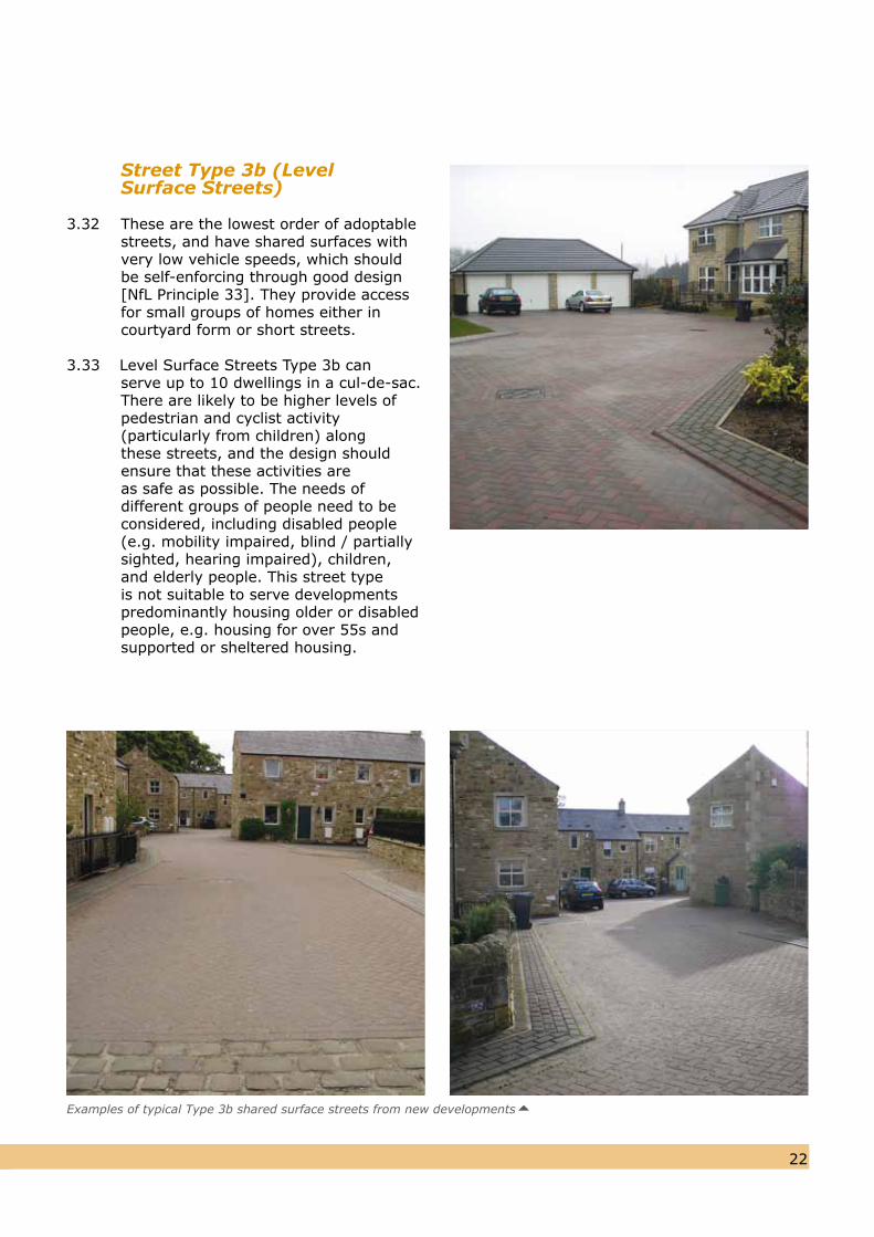
Street Type 3b (Level Surface Streets)
3.32 These are the lowest order of adoptable streets, and have shared surfaces withvery low vehicle speeds, which should be self-enforcing through good design [NfL Principle 33]. They provide access for small groups of homes either in courtyard form or short streets.
3.33 Level Surface Streets Type 3b can serve up to 10 dwellings in a cul-de-sac.There are likely to be higher levels ofpedestrian and cyclist activity (particularly from children) along these streets, and the design should ensure that these activities are as safe as possible. The needs of different groups of people need to be considered, including disabled people (e.g. mobility impaired, blind / partially sighted, hearing impaired), children, and elderly people. This street type is not suitable to serve developments predominantly housing older or disabled people, e.g. housing for over 55s and supported or sheltered housing.
Examples of typical Type 3b shared surface streets from new developments
2423
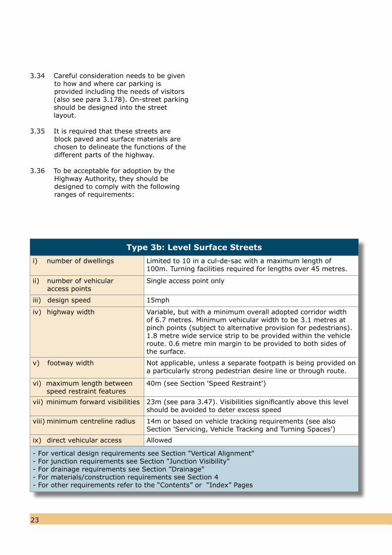
Type 3b: Level Surface Streets
i) number of dwellings Limited to 10 in a cul-de-sac with a maximum length of 100m. Turning facilities required for lengths over 45 metres.
ii) number of vehicular 0 access points
Single access point only
iii) design speed 15mph
iv) highway width Variable, but with a minimum overall adopted corridor widthof 6.7 metres. Minimum vehicular width to be 3.1 metres atpinch points (subject to alternative provision for pedestrians).1.8 metre wide service strip to be provided within the vehicleroute. 0.6 metre min margin to be provided to both sides ofthe surface.
v) footway width Not applicable, unless a separate footpath is being provided on a particularly strong pedestrian desire line or through route.
vi) maximum length between speed restraint features
40m (see Section 'Speed Restraint')
vii) minimum forward visibilities 23m (see para 3.47). Visibilities significantly above this levelshould be avoided to deter excess speed
viii) minimum centreline radius 14m or based on vehicle tracking requirements (see alsoSection 'Servicing, Vehicle Tracking and Turning Spaces')
ix) direct vehicular access Allowed
- For vertical design requirements see Section "Vertical Alignment"- For junction requirements see Section "Junction Visibility"- For drainage requirements see Section "Drainage"- For materials/construction requirements see Section 4- For other requirements refer to the “Contents” or “Index” Pages
3.34 Careful consideration needs to be givento how and where car parking is provided including the needs of visitors
(also see para 3.178). On-street parking should be designed into the street layout.
3.35 It is required that these streets areblock paved and surface materials are chosen to delineate the functions of thedifferent parts of the highway.
3.36 To be acceptable for adoption by theHighway Authority, they should bedesigned to comply with the followingranges of requirements:
2423
Street Type 4 (Home Zones)
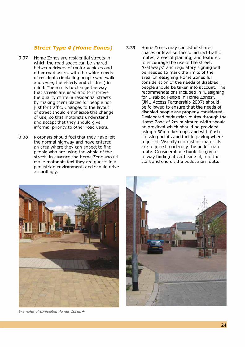
3.37 Home Zones are residential streets in which the road space can be shared between drivers of motor vehicles and other road users, with the wider needs of residents (including people who walk and cycle, the elderly and children) in mind. The aim is to change the way that streets are used and to improve the quality of life in residential streets by making them places for people not just for traffic. Changes to the layout of street should emphasise this change of use, so that motorists understand and accept that they should give informal priority to other road users.
3.38 Motorists should feel that they have leftthe normal highway and have entered an area where they can expect to find people who are using the whole of thestreet. In essence the Home Zone shouldmake motorists feel they are guests in apedestrian environment, and should driveaccordingly.
3.39 Home Zones may consist of shared spaces or level surfaces, indirect traffic routes, areas of planting, and features to encourage the use of the street. “Gateways” and regulatory signing will be needed to mark the limits of the area. In designing Home Zones full consideration of the needs of disabled people should be taken into account. The recommendations included in “Designing for Disabled People in Home Zones”, (JMU Access Partnership 2007) should be followed to ensure that the needs of disabled people are properly considered. Designated pedestrian routes through the Home Zone of 2m minimum width should be provided which should be provided using a 30mm kerb upstand with flush crossing points and tactile paving where required. Visually contrasting materials are required to identify the pedestrian route. Consideration should be given to way finding at each side of, and the start and end of, the pedestrian route.
Examples of completed Homes Zones
2625
3.40 Design guidance and other information onHome Zones, including links to related websites, is available through the Institution of Highway Incorporated Engineers at www.ihie.org.uk andwww.homezones.org.uk.
3.41 Procedural guidance is set out within the Department for Transport’s Circular 02/2006 “The Quiet Lanes and Home Zones (England) Regulations 2006”. Home Zones shall be used only wheretraffic flows are no more than about 100weekday pm peak hour vehicle movements,so the number of dwellings will vary withthe location and nature of the development.
3.42 The statutory process for the designation of a Home Zone and the making of theassociated use and speed orders requiresthat there is consultation with local groups,and in particular the residents of the area. While this does not present aproblem with Home Zones in existingstreets, there is an apparent difficulty withnew build developments in that streetsare normally well on the way to beingbuilt when residents begin to move in.
3.43 It is therefore required that aninformation pack is given to all purchasers,setting out general information on HomeZones, together with the key proposals for the site (including a draft wording of the use and speed orders) explaining the way in which the streets will be managed and maintained.
3.44 Purchasers will then be asked to sign thisdocument, stating that they have understood and agree in principle with the Home Zone proposals. Once the streets are open to the public, Leeds City Council will carry out the formal consultation process to enable the Home Zone to be designated and the Orders made at the Developer’s expense.
3.45 Streets designed to Home Zone standards will only be accepted if Home Zone designation is proposed and is realistically achievable.
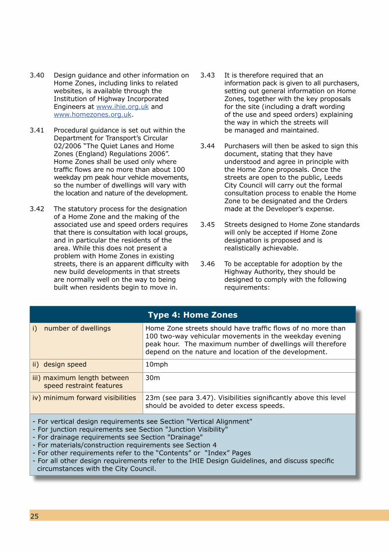
3.46 To be acceptable for adoption by the Highway Authority, they should be designed to comply with the following requirements:
Type 4: Home Zones
i) number of dwellings Home Zone streets should have traffic flows of no more than 100 two-way vehicular movements in the weekday evening peak hour. The maximum number of dwellings will therefore depend on the nature and location of the development.
ii) design speed 10mph
iii) maximum length between speed restraint features
30m
iv) minimum forward visibilities 23m (see para 3.47). Visibilities significantly above this levelshould be avoided to deter excess speeds.
- For vertical design requirements see Section "Vertical Alignment"- For junction requirements see Section "Junction Visibility"- For drainage requirements see Section "Drainage"- For materials/construction requirements see Section 4- For other requirements refer to the “Contents” or “Index” Pages- For all other design requirements refer to the IHIE Design Guidelines, and discuss specific circumstances with the City Council.
2625
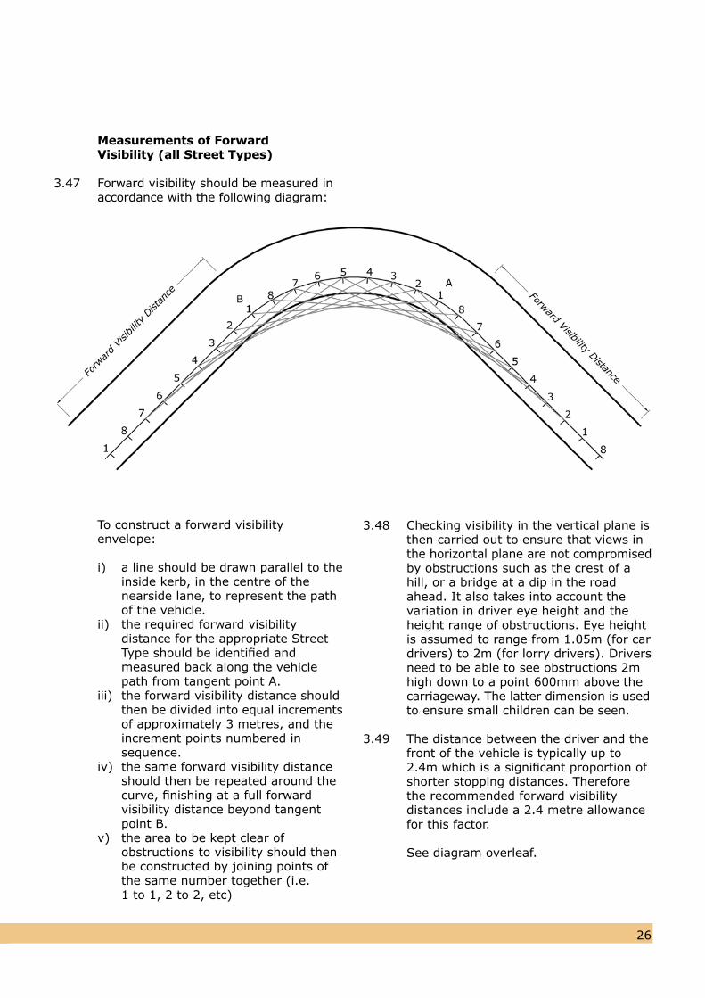
Measurements of Forward Visibility (all Street Types)
3.47 Forward visibility should be measured in accordance with the following diagram:
To construct a forward visibilityenvelope:
i) a line should be drawn parallel to the inside kerb, in the centre of the nearside lane, to represent the path of the vehicle.ii) the required forward visibility distance for the appropriate Street Type should be identified and measured back along the vehicle path from tangent point A.iii) the forward visibility distance should then be divided into equal increments of approximately 3 metres, and the increment points numbered in sequence.iv) the same forward visibility distance should then be repeated around the curve, finishing at a full forward visibility distance beyond tangent point B.v) the area to be kept clear of obstructions to visibility should then be constructed by joining points of the same number together (i.e. 1 to 1, 2 to 2, etc)
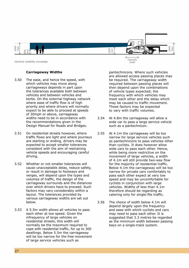
3.48 Checking visibility in the vertical plane isthen carried out to ensure that views inthe horizontal plane are not compromisedby obstructions such as the crest of ahill, or a bridge at a dip in the road ahead. It also takes into account the variation in driver eye height and the height range of obstructions. Eye heightis assumed to range from 1.05m (for cardrivers) to 2m (for lorry drivers). Driversneed to be able to see obstructions 2mhigh down to a point 600mm above thecarriageway. The latter dimension is usedto ensure small children can be seen.
3.49 The distance between the driver and thefront of the vehicle is typically up to 2.4m which is a significant proportion of shorter stopping distances. Thereforethe recommended forward visibility distances include a 2.4 metre allowancefor this factor.
See diagram overleaf.
2827
Carriageway Widths
3.50 The ease, and hence the speed, withwhich vehicles may move along carriageways depends in part upon the tolerances available both between vehicles and between vehicles and kerbs. On the external highway network where ease of traffic flow is of high priority and where drivers will normally expect to be able to proceed at speeds of 30mph or above, carriageway widths need to be in accordance with the recommendations given in the Design Manual for Roads and Bridges.
3.51 On residential streets however, wheretraffic flows are light and where journeysare starting or ending, drivers may beexpected to accept smaller tolerancesconsistent with the aim of restrainingvehicle speeds and encouraging carefuldriving.
3.52 Whether or not smaller tolerances willcause unacceptable delay, reduce safety,or result in damage to footways and verges, will depend upon the types andvolumes of traffic, the design of thecarriageway surrounds and the distancesover which drivers have to proceed. Suchfactors may vary considerably within alayout. The tolerances provided byvarious carriageway widths are set outbelow.
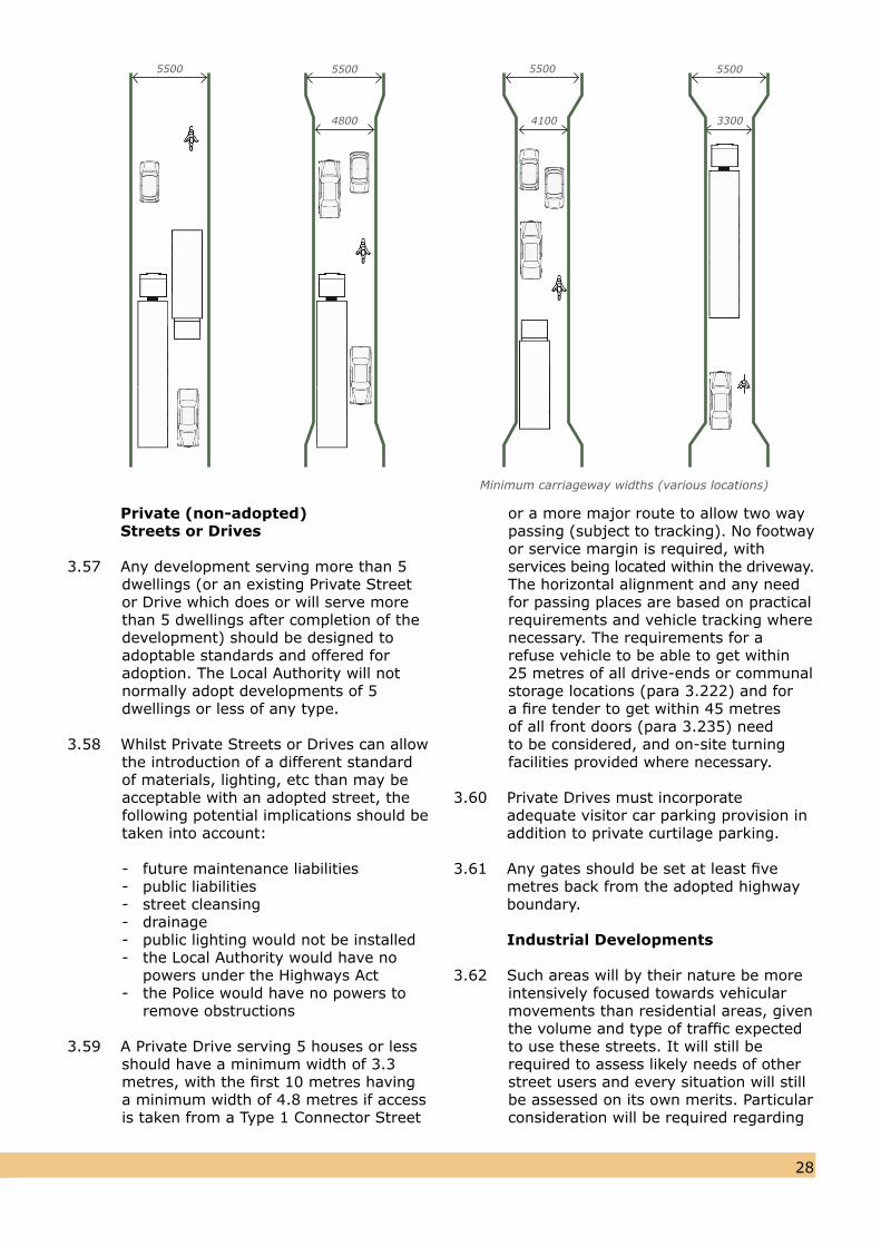
3.53 A 5.5m width allows all vehicles to pass each other at low speed. Given the infrequency of large vehicles on residential streets, this width will normally be the maximum required to
cope with residential traffic, for up to 300dwellings. Below 5.5m the carriagewaywill be too narrow for the free movementof large service vehicles such as
pantechnicons. Where such vehiclesare allowed access passing places maybe required. The carriageway widthrequired between passing places willthen depend upon the combinations of vehicle types expected; the frequency with which vehicles may meet each other and the delay which may be caused to traffic movement. These factors may be expected to vary with traffic volumes.
3.54 At 4.8m the carriageway will allow a wide car to pass a large service vehicle such as a pantechnicon.
3.55 At 4.1m the carriageway will be toonarrow for large service vehicles such as pantechnicons to pass vehicles other than cyclists. It does however allow wide cars to pass each other. Hence, while being more restrictive on the movement of large vehicles, a width of 4.1m will still provide two-way flow for the majority of residential traffic. Below 4.1m the carriageway will be too narrow for private cars comfortably to pass each other expect at very lowspeed and may be uncomfortable forcyclists in conjunction with largevehicles. Widths of less than 4.1mtherefore should be regarding ascatering only for single-file traffic.
3.56 The choice of width below 4.1m willdepend largely upon the frequency and ease with which cyclists and cars may need to pass each other. It is suggested that 3.3 metres be regarded as the minimum width between passing bays on a single-track system.
Vertical visibility envelopeTypically
2400
2000
max
600
min
1050
min 2000
max
2827
Private (non-adopted) Streets or Drives
3.57 Any development serving more than 5dwellings (or an existing Private Street or Drive which does or will serve more than 5 dwellings after completion of thedevelopment) should be designed toadoptable standards and offered for adoption. The Local Authority will notnormally adopt developments of 5dwellings or less of any type.
3.58 Whilst Private Streets or Drives can allowthe introduction of a different standard of materials, lighting, etc than may beacceptable with an adopted street, thefollowing potential implications should betaken into account:
- future maintenance liabilities- public liabilities- street cleansing - drainage- public lighting would not be installed- the Local Authority would have no powers under the Highways Act- the Police would have no powers to remove obstructions
3.59 A Private Drive serving 5 houses or lessshould have a minimum width of 3.3 metres, with the first 10 metres having a minimum width of 4.8 metres if access is taken from a Type 1 Connector Street
or a more major route to allow two waypassing (subject to tracking). No footwayor service margin is required, with services being located within the driveway. The horizontal alignment and any need for passing places are based on practical requirements and vehicle tracking wherenecessary. The requirements for a refuse vehicle to be able to get within 25 metres of all drive-ends or communal storage locations (para 3.222) and for a fire tender to get within 45 metres of all front doors (para 3.235) need to be considered, and on-site turning facilities provided where necessary.
3.60 Private Drives must incorporate adequate visitor car parking provision in addition to private curtilage parking.
3.61 Any gates should be set at least five metres back from the adopted highway boundary.
Industrial Developments
3.62 Such areas will by their nature be moreintensively focused towards vehicular movements than residential areas, given the volume and type of traffic expected to use these streets. It will still be required to assess likely needs of other street users and every situation will still be assessed on its own merits. Particular consideration will be required regarding
Minimum carriageway widths (various locations)
5500 5500 5500 5500
330041004800
HGV/cyclist interaction. Direct, safe and convenient pedestrian routes should be provided to public transport stops.
3.63 Industrial roads are categorised as Majoror Minor, with the same layout standards being applicable in each case. The difference is the likely number of Heavy Goods Vehicles (HGVs) and therefore the construction details vary (see Section 4). Where a Minor Industrial Road is intended to serve a mainly B1 office development (with a very low number of HGVs) there may be flexibility to vary certain requirements (e.g. radii and turning facilities).
3.64 Major Industrial Roads may serve industrial or commercial developments of up to 20 Hectares. Above this levelroads should be designed in accordance with the Design Manual for Roads andBridges. Commercial vehicles in residentialareas are obviously undesirable, and for this reason the design of a large scale industrial estate should try to produce a layout which is self-contained and which segregates industrial from local/residential traffic. It should, however, be acknowledged that pedestrian and
3029
cycle movements are likely to be just as numerous on industrial estate roads as people travel to their place of work.
3.65 In principle mixed use schemes will be encouraged, and where a mixed use scheme has been accepted by the LocalAuthority as being appropriate, thenSection "Speed Restraint" should bereferred to for design guidance.
3.66 Small scale direct individual access is notto be encouraged on Major Industrial Roads, and a proper hierarchy should beused within an estate so that this formof access is taken from a Minor IndustrialRoad.
3.67 Minor Industrial Roads may serve industrial or commercial developments of up to 8 hectares (or an industrialbuilding with a gross floor area of 40,000square metres), and direct frontage access to individual premises is allowed.
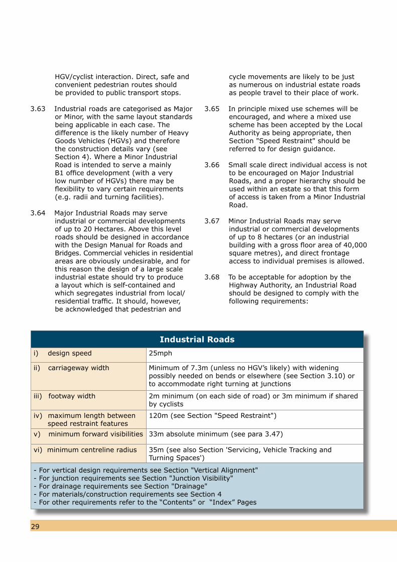
3.68 To be acceptable for adoption by theHighway Authority, an Industrial Roadshould be designed to comply with thefollowing requirements:
Industrial Roads
i) design speed 25mph
ii) carriageway width Minimum of 7.3m (unless no HGV’s likely) with widening possibly needed on bends or elsewhere (see Section 3.10) orto accommodate right turning at junctions
iii) footway width 2m minimum (on each side of road) or 3m minimum if sharedby cyclists
iv) maximum length between speed restraint features
120m (see Section "Speed Restraint")
v) minimum forward visibilities 33m absolute minimum (see para 3.47)
vi) minimum centreline radius 35m (see also Section 'Servicing, Vehicle Tracking andTurning Spaces')
- For vertical design requirements see Section "Vertical Alignment"- For junction requirements see Section "Junction Visibility"- For drainage requirements see Section "Drainage"- For materials/construction requirements see Section 4- For other requirements refer to the “Contents” or “Index” Pages
3029
3.69 Some developments propose the formation of small groups of industrial units designed for occupation by eitherone or two man operations.
3.70 The function of these units is to providea purpose-made “industrial nursery” for businesses, from which a small company can grow and become established. Oncethis purpose is fulfilled it is expected thatlarger premises will be needed by thecompany, and on relocation of thebusiness, the nursery unit may then berelet.
3.71 It is usual for the industrial units to be upto approximately 150m² in floor area,and generally of a system built construction, sited around a central turning area. Each unit has its own forecourt which acts asboth an unloading/loading area and as acasual car parking space. Where additionalstaff car parking is required this is normally provided in a communal area, conveniently located adjacent to the turning head. In order for this Industrial “Courtyard” to properly function a minimum of two staff car parking spacesmust be provided to each unit.
3.72 The shared turning head shall be a minimum of 20m x 20m to enable either a 10m rigid or 16.5m articulated vehicle to turn clear of the unit forecourts.
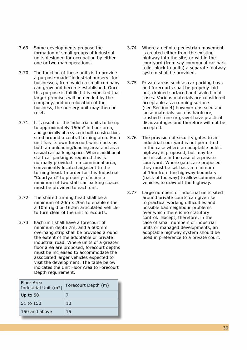
3.73 Each unit shall have a forecourt of minimum depth 7m, and a 600mm overhang strip shall be provided aroundthe extent of the adoptable or privateindustrial road. Where units of a greaterfloor area are proposed, forecourt depthsmust be increased to accommodate the associated larger vehicles expected tovisit the development. The table belowindicates the Unit Floor Area to ForecourtDepth requirement.
3.74 Where a definite pedestrian movement is created either from the existing highway into the site, or within the courtyard (from say communal car parktoilet block to units) a separate footwaysystem shall be provided.
3.75 Private areas such as car parking baysand forecourts shall be properly laidout, drained surfaced and sealed in allcases. Various materials are considered acceptable as a running surface(see Section 4) however unsealed andloose materials such as hardcore,crushed stone or gravel have practicaldisadvantages and therefore will not beaccepted.
3.76 The provision of security gates to an industrial courtyard is not permitted in the case where an adoptable public highway is proposed, but may be permissible in the case of a private courtyard. Where gates are proposed they must be set back a minimum of 15m from the highway boundary (back of footway) to allow commercial vehicles to draw off the highway.
3.77 Large numbers of industrial units sited around private courts can give rise to practical working difficulties and possible bad neighbour problems over which there is no statutory control. Except, therefore, in the case of small numbers of industrial units or managed developments, an adoptable highway system should be used in preference to a private court.
Floor Area Industrial Unit (m²) Forecourt Depth (m)
Up to 50 7
51 to 150 10
150 and above 15
3231
Mixed Use Schemes
3.78 As various local and national planning policies are encouraging the greater introduction of mixed use schemes (i.e.residential and commercial served fromthe same access) highway and streetdesign standards need to be sufficientlyflexible to accept such access streets foradoption.
3.79 Connector Streets (Type 1 as described in paragraphs 3.18 to 3.22) can bedesigned to accommodate a mix ofresidential and commercial traffic wherenecessary.
3.80 Such a Street Type will be appropriate where the peak hour traffic flow is not expected to exceed that which could be generated by 700 dwellings (i.e. in the order of 455 two-way peak hour vehicle movements). Above this level the DesignManual for Roads and Bridges should beused, although this should be discussedwith the City Council.
3.81 Particular care will need to be taken in the design of such schemes, where there is the potential for a greater degree ofpedestrian-vehicular conflict than usual. This may require additional speed restraints or other measures to ensure the safety of vulnerable road users.
3.82 The carriageway widths and otherstandards will be partly dependent on thepercentage of larger vehicles which areexpected.
3.83 The point at which a mixed use scheme should be designed as an Industrial Roadshould be discussed with the City Council.
Speed Restraint 3.84 To ensure that the design speeds
identified for each type of street are not exceeded, it is necessary to design speed restraint measures into the development. If they are required, they should be designed from the beginning of the process, and not introduced as
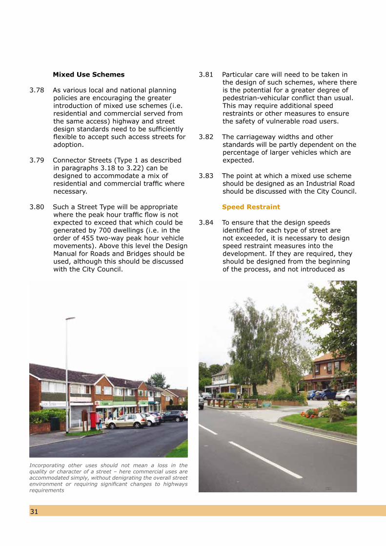
Incorporating other uses should not mean a loss in the quality or character of a street – here commercial uses are accommodated simply, without denigrating the overall street environment or requiring significant changes to highways requirements
3231
an after thought [NfL Principles 24 and 34]. They must be justified within the Design and Access Statement (see paragraph 2.09 (i)). For speed restraint on bus routes the preference from the bus operator’s is for horizontal deflection rather than vertical deflection.
3.85 The speed of vehicles is the key factor inimproving road safety and minimising future potential accidents. There is a significant lowering of the severity of accidents involving pedestrians and other vulnerable road users when the speed of the vehicle involved is less than 20mph. For this reason all Local Residential Streets (Type 2) should bedesigned to be self enforcing to keepspeeds below 20mph, Shared SpaceStreets (Type 3) below 15 mph, andHome Zones (Type 4) below 10 mph.Connector Streets (Type 1) should bedesigned to control speeds to 25mph or20 mph, depending on the circumstances.
3.86 Speed restraint is not just a matter ofusing the engineering features described in this section but is an inherent feature of the overall design. A driver’s perception of a safe speed is also materially affected by the spacing, form and proximity of the buildings served by the street, plus the surface materials used and the effective use of hard and soft landscape elements. Wherever possible ‘natural’ speed reducing features, which respond to the built form and layout of a development, should be used to prevent the traffic infrastructure dominating the visual appearance of the street. Closing speeds need to be taken into account in locations where the carriageway is not wide enough to accommodate two-way passing of vehicles.
3.87 For all of the following speed restraint features on new layouts it is not intended to sign the features. Thereforeover-engineered layouts requiring excessive signage will not be acceptedon new developments.
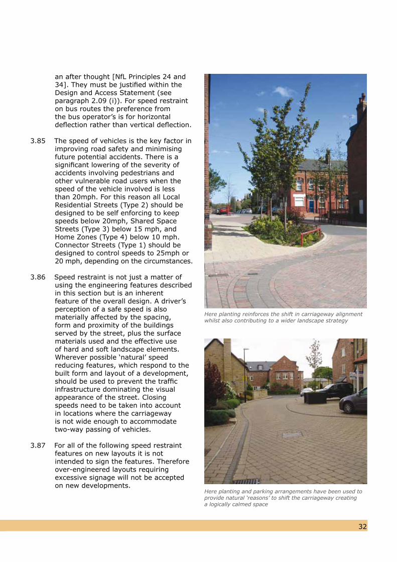
Here planting reinforces the shift in carriageway alignment whilst also contributing to a wider landscape strategy
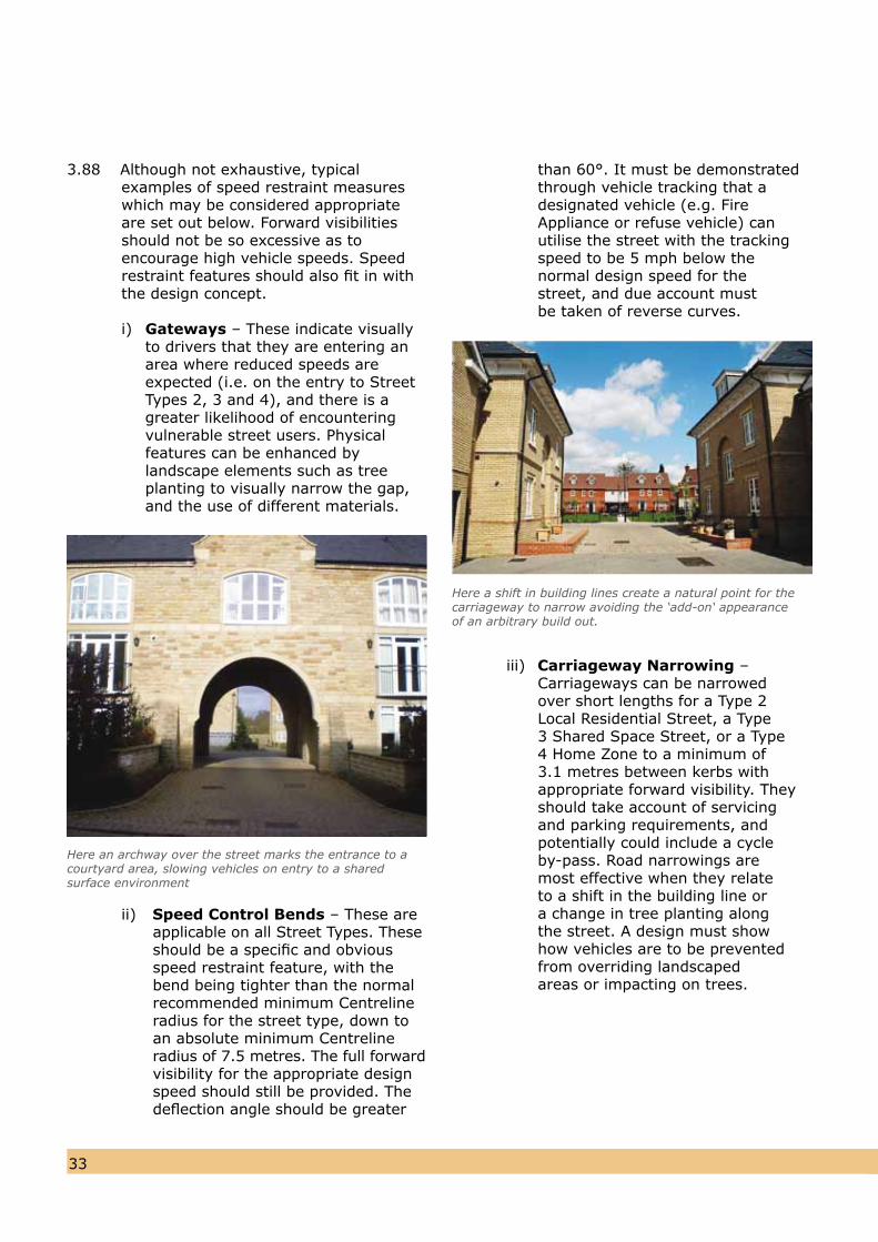
Here planting and parking arrangements have been used to provide natural ‘reasons’ to shift the carriageway creatinga logically calmed space
3.88 Although not exhaustive, typical examples of speed restraint measures which may be considered appropriate are set out below. Forward visibilities should not be so excessive as to encourage high vehicle speeds. Speedrestraint features should also fit in withthe design concept.
i) Gateways – These indicate visually to drivers that they are entering an area where reduced speeds are expected (i.e. on the entry to Street Types 2, 3 and 4), and there is a greater likelihood of encountering vulnerable street users. Physical features can be enhanced by landscape elements such as tree planting to visually narrow the gap, and the use of different materials.
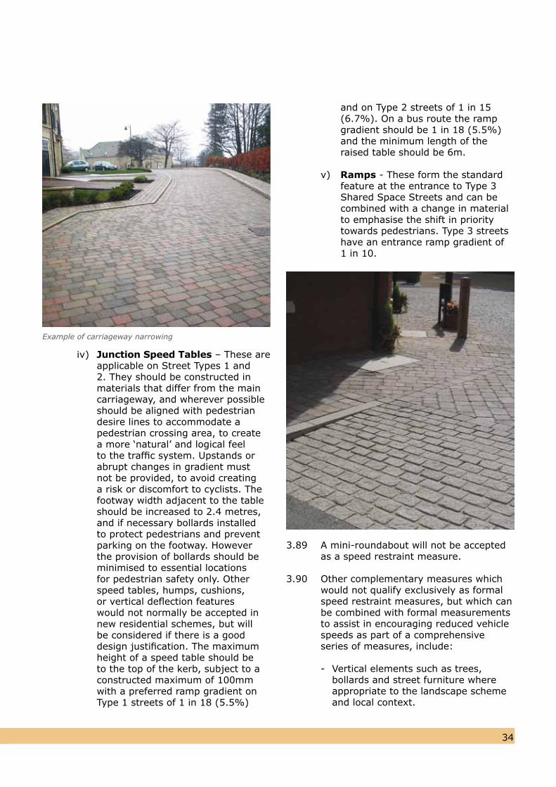
Here an archway over the street marks the entrance to acourtyard area, slowing vehicles on entry to a sharedsurface environment
ii) Speed Control Bends – These are applicable on all Street Types. Theseshould be a specific and obviousspeed restraint feature, with thebend being tighter than the normal recommended minimum Centreline radius for the street type, down toan absolute minimum Centreline radius of 7.5 metres. The full forwardvisibility for the appropriate design speed should still be provided. Thedeflection angle should be greater
than 60°. It must be demonstrated through vehicle tracking that adesignated vehicle (e.g. Fire Appliance or refuse vehicle) can utilise the street with the tracking speed to be 5 mph below the normal design speed for the street, and due account must be taken of reverse curves.
iii) Carriageway Narrowing – Carriageways can be narrowed over short lengths for a Type 2 Local Residential Street, a Type 3 Shared Space Street, or a Type 4 Home Zone to a minimum of 3.1 metres between kerbs with appropriate forward visibility. They should take account of servicing and parking requirements, and potentially could include a cycle by-pass. Road narrowings are most effective when they relate to a shift in the building line or a change in tree planting along the street. A design must show how vehicles are to be prevented from overriding landscaped areas or impacting on trees.
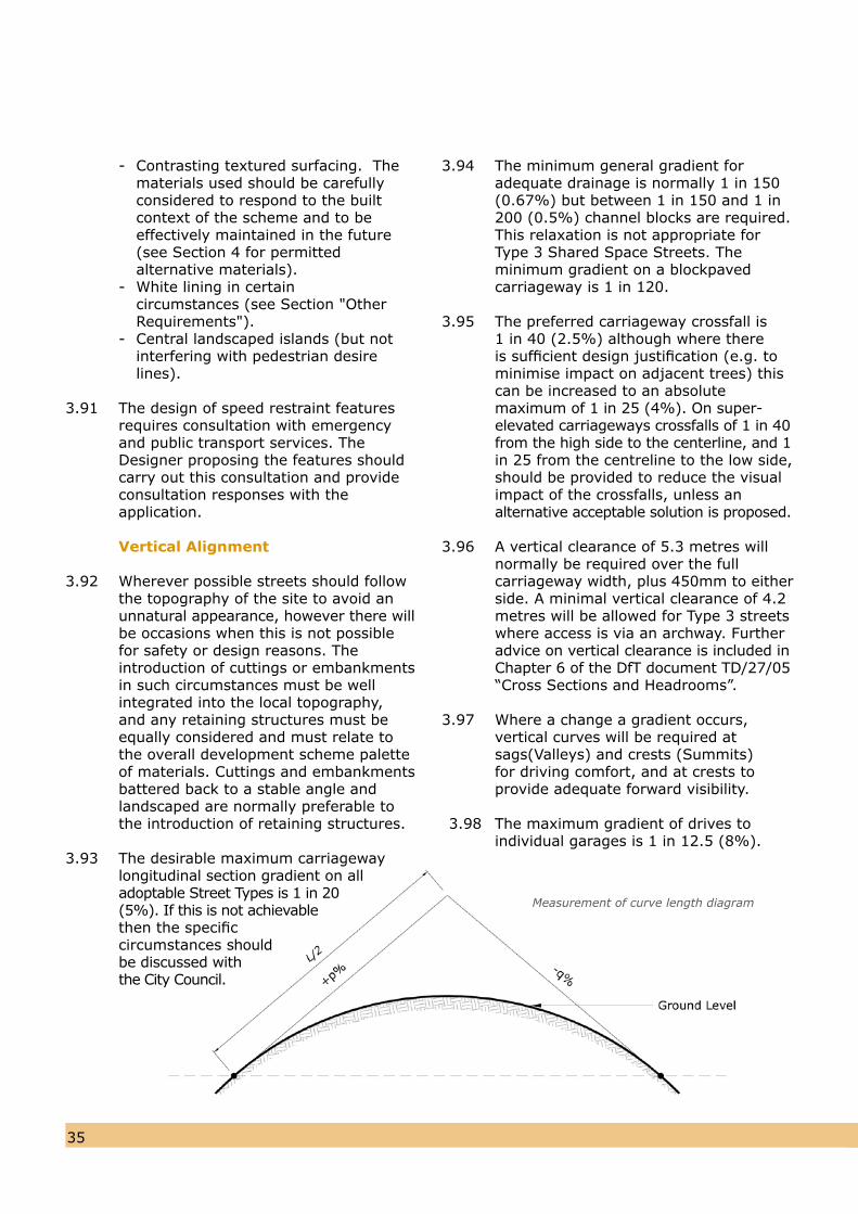
Here a shift in building lines create a natural point for thecarriageway to narrow avoiding the ‘add-on‘ appearanceof an arbitrary build out.
3433
iv) Junction Speed Tables – These areapplicable on Street Types 1 and 2. They should be constructed in materials that differ from the main carriageway, and wherever possible should be aligned with pedestrian desire lines to accommodate a pedestrian crossing area, to create a more ‘natural’ and logical feel to the traffic system. Upstands or abrupt changes in gradient must not be provided, to avoid creating a risk or discomfort to cyclists. The footway width adjacent to the table should be increased to 2.4 metres, and if necessary bollards installed to protect pedestrians and prevent parking on the footway. However the provision of bollards should be minimised to essential locations for pedestrian safety only. Other speed tables, humps, cushions, or vertical deflection features would not normally be accepted in new residential schemes, but will be considered if there is a good design justification. The maximum height of a speed table should be to the top of the kerb, subject to a constructed maximum of 100mm with a preferred ramp gradient on Type 1 streets of 1 in 18 (5.5%)
3433
Example of carriageway narrowing
and on Type 2 streets of 1 in 15 (6.7%). On a bus route the ramp gradient should be 1 in 18 (5.5%) and the minimum length of the raised table should be 6m.
v) Ramps - These form the standardfeature at the entrance to Type 3Shared Space Streets and can becombined with a change in materialto emphasise the shift in priority towards pedestrians. Type 3 streetshave an entrance ramp gradient of1 in 10.
3.89 A mini-roundabout will not be accepted as a speed restraint measure.
3.90 Other complementary measures whichwould not qualify exclusively as formal speed restraint measures, but which can be combined with formal measurements to assist in encouraging reduced vehicle speeds as part of a comprehensive series of measures, include:
- Vertical elements such as trees, bollards and street furniture where appropriate to the landscape scheme and local context.
- Contrasting textured surfacing. The materials used should be carefully considered to respond to the built context of the scheme and to be effectively maintained in the future (see Section 4 for permitted alternative materials).- White lining in certain circumstances (see Section "Other Requirements").- Central landscaped islands (but not interfering with pedestrian desire lines).
3.91 The design of speed restraint featuresrequires consultation with emergencyand public transport services. The Designer proposing the features shouldcarry out this consultation and provideconsultation responses with theapplication.
Vertical Alignment
3.92 Wherever possible streets should followthe topography of the site to avoid anunnatural appearance, however there willbe occasions when this is not possible for safety or design reasons. The introduction of cuttings or embankments in such circumstances must be well integrated into the local topography, and any retaining structures must be equally considered and must relate to the overall development scheme palette of materials. Cuttings and embankments battered back to a stable angle and landscaped are normally preferable to the introduction of retaining structures.
3.93 The desirable maximum carriagewaylongitudinal section gradient on alladoptable Street Types is 1 in 20(5%). If this is not achievablethen the specificcircumstances should be discussed withthe City Council.
3.94 The minimum general gradient foradequate drainage is normally 1 in 150(0.67%) but between 1 in 150 and 1 in200 (0.5%) channel blocks are required.This relaxation is not appropriate for Type 3 Shared Space Streets. The minimum gradient on a blockpaved carriageway is 1 in 120.
3.95 The preferred carriageway crossfall is1 in 40 (2.5%) although where there is sufficient design justification (e.g. to minimise impact on adjacent trees) thiscan be increased to an absolute maximum of 1 in 25 (4%). On super-elevated carriageways crossfalls of 1 in 40from the high side to the centerline, and 1in 25 from the centreline to the low side,should be provided to reduce the visualimpact of the crossfalls, unless analternative acceptable solution is proposed.
3.96 A vertical clearance of 5.3 metres will normally be required over the full carriageway width, plus 450mm to eitherside. A minimal vertical clearance of 4.2metres will be allowed for Type 3 streetswhere access is via an archway. Furtheradvice on vertical clearance is included inChapter 6 of the DfT document TD/27/05“Cross Sections and Headrooms”.
3.97 Where a change a gradient occurs, vertical curves will be required at sags(Valleys) and crests (Summits) for driving comfort, and at crests to provide adequate forward visibility.
3.98 The maximum gradient of drives to individual garages is 1 in 12.5 (8%).
3635
Measurement of curve length diagram
3635
3.100 The lowest point of any adoptable carriageway should be 600mm abovethe 1 in 100 year river flood level asidentified by the approved flood riskassessment. If there are justifiable reasonswhy this level may not be achievable inany particular circumstance, this mattermust be discussed with the City Council.
Junctions and Visibility
Principles
3.101 The geometry of new junctions (either onto the existing external highway network or within the development itself) must take into account both the type of traffic on the minor route, and also the existing (or likely future) traffic flows and speeds on the major route.
3.102 The number of new accesses, junctions, and private means of access will be restricted in the vicinity of sites which generate high pedestrian flows (e.g. schools) and those which are considered acceptable should not involve reversing manoeuvres onto or off the street.
3.103 As a general principle junctions should be avoided near the crest of a street, or on a bend.
3.104 The minor route should normally meet the major route at right angles, althoughthe minor route may deviate by up to 10º
where it will not adversely affect vehicleswept paths.
3.105 “Manual for Streets” (MfS) introduced reduced visibility guidelines, on routes within built-up areas having 85%ile wet weather vehicle speeds of 37 mph or less. For the purposes of this Design Guide, the MfS recommended visibilities are considered to be appropriate in the following circumstances:
i) Within new residential developments themselves ii) Plus the access junction onto external highway network, where the major route meets all of the following in the vicinity of the junction:
a) It is not a Distributor Road or Strategic Route (See Appendix G) b) It is within a built-up area c) The eighty-fifth percentile wet weather speed is 37 mph or less d) The place function of the street is more important than the movement function.
3.106 The question of whether a particular
location is “built up” will need to be discussed with the City Council, but ingeneral terms it relates to an area wherethere is development on at least one sideof the road or street, with accesses, junctions and other features which willinfluence driver behaviour. The definitionof “Distributor Road” and “Strategic Route” is based on the City Council’s maintenance hierarchy, with the routescurrently classified as such being setout in Appendix G.
3.107 In all other circumstances the visibility guidelines set out in paragraph 3.120 should be utilised for priority junctions unless otherwise agreed by the CityCouncil. For non-priority and other junctions, the design guidance will be asset out in DMRB.
Measurement of Splays
3.108 The distance back along the minor arm from which visibility is measured is
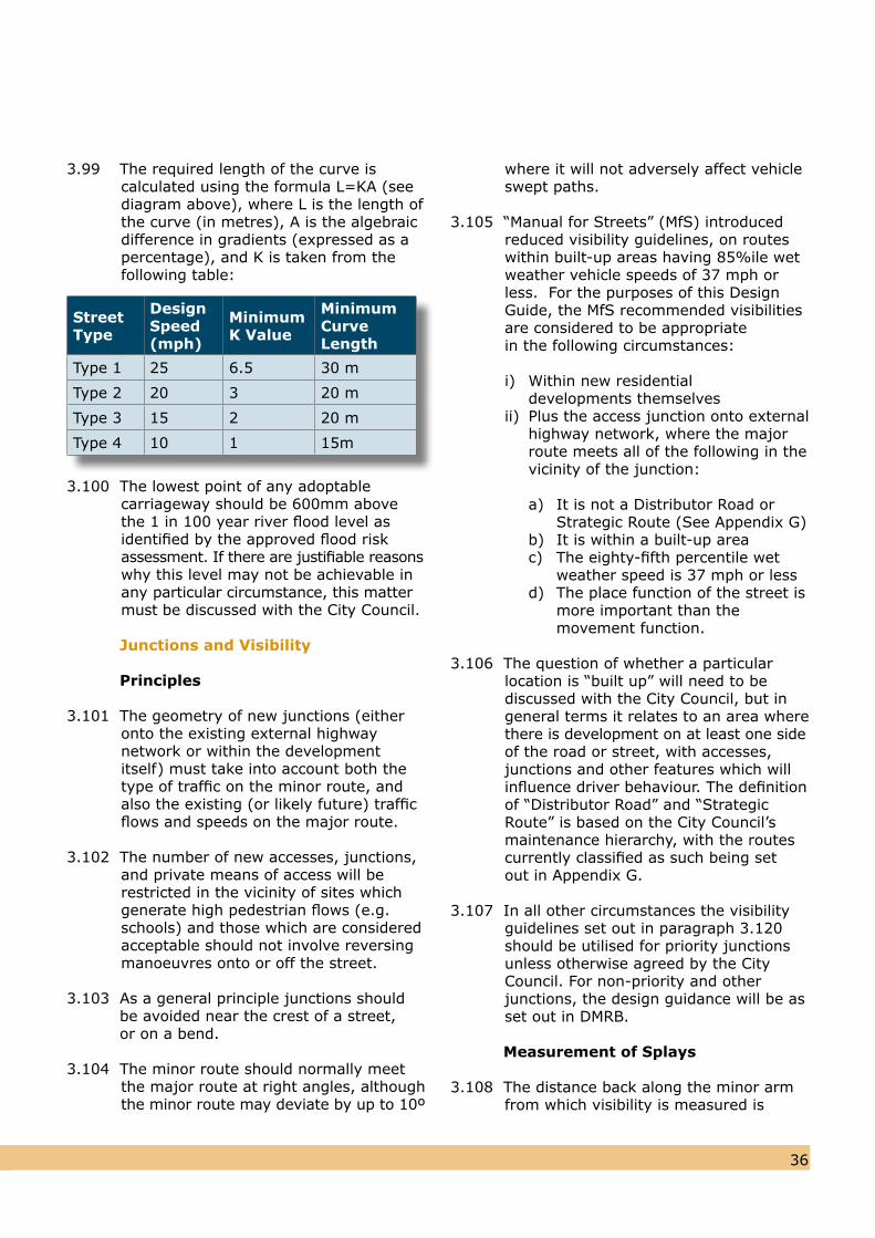
3.99 The required length of the curve iscalculated using the formula L=KA (seediagram above), where L is the length ofthe curve (in metres), A is the algebraicdifference in gradients (expressed as apercentage), and K is taken from thefollowing table:
Street Type
Design Speed (mph)
Minimum K Value
Minimum Curve Length
Type 1 25 6.5 30 m
Type 2 20 3 20 m
Type 3 15 2 20 m
Type 4 10 1 15m
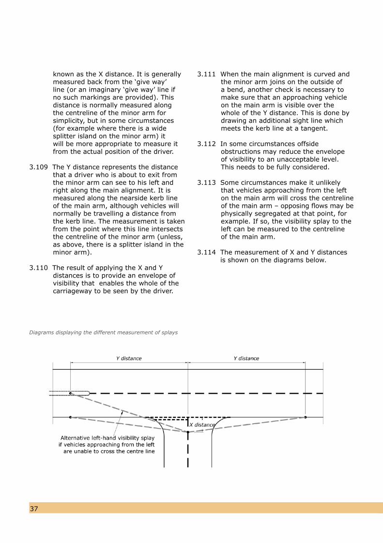
known as the X distance. It is generally measured back from the ‘give way’ line (or an imaginary ‘give way’ line if no such markings are provided). This distance is normally measured along the centreline of the minor arm for simplicity, but in some circumstances (for example where there is a wide splitter island on the minor arm) it will be more appropriate to measure it from the actual position of the driver.
3.109 The Y distance represents the distance that a driver who is about to exit from the minor arm can see to his left and right along the main alignment. It is measured along the nearside kerb line of the main arm, although vehicles willnormally be travelling a distance from the kerb line. The measurement is takenfrom the point where this line intersectsthe centreline of the minor arm (unless,as above, there is a splitter island in theminor arm).
3.110 The result of applying the X and Ydistances is to provide an envelope of visibility that enables the whole of the carriageway to be seen by the driver.
3837
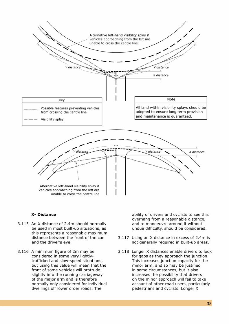
3.111 When the main alignment is curved andthe minor arm joins on the outside of a bend, another check is necessary to make sure that an approaching vehicle on the main arm is visible over the whole of the Y distance. This is done by drawing an additional sight line which meets the kerb line at a tangent.
3.112 In some circumstances offside obstructions may reduce the envelope of visibility to an unacceptable level. This needs to be fully considered.
3.113 Some circumstances make it unlikely that vehicles approaching from the left on the main arm will cross the centreline of the main arm – opposing flows may bephysically segregated at that point, forexample. If so, the visibility splay to theleft can be measured to the centrelineof the main arm.
3.114 The measurement of X and Y distances is shown on the diagrams below.
Diagrams displaying the different measurement of splays
3837
X- Distance
3.115 An X distance of 2.4m should normallybe used in most built-up situations, asthis represents a reasonable maximumdistance between the front of the carand the driver’s eye.
3.116 A minimum figure of 2m may be considered in some very lightly-trafficked and slow-speed situations, but using this value will mean that the front of some vehicles will protrude slightly into the running carriageway of the major arm and is therefore normally only considered for individual dwellings off lower order roads. The
ability of drivers and cyclists to see this overhang from a reasonable distance, and to manoeuvre around it without undue difficulty, should be considered.
3.117 Using an X distance in excess of 2.4m is not generally required in built-up areas.
3.118 Longer X distances enable drivers to look for gaps as they approach the junction. This increases junction capacity for the minor arm, and so may be justified in some circumstances, but it also increases the possibility that drivers on the minor approach will fail to take account of other road users, particularly pedestrians and cyclists. Longer X
Note
All land within visibility splays should be adopted to ensure long term provision and maintenance is guaranteed.
distances may also result in more shunt accidents on the minor arm. TRL Report No. 184 found that accident risk increased with greater minor-road sight distances. Therefore an x-distance of 4.5 metres will only be required where there is likely to be a capacity issue.
Y – Distance
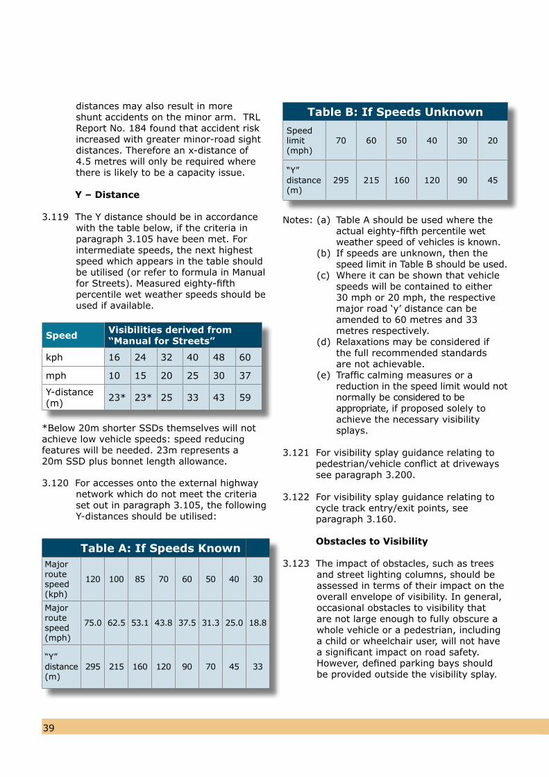
3.119 The Y distance should be in accordancewith the table below, if the criteria in paragraph 3.105 have been met. For intermediate speeds, the next highest speed which appears in the table shouldbe utilised (or refer to formula in Manualfor Streets). Measured eighty-fifthpercentile wet weather speeds should beused if available.
*Below 20m shorter SSDs themselves will not achieve low vehicle speeds: speed reducing features will be needed. 23m represents a 20m SSD plus bonnet length allowance.
3.120 For accesses onto the external highwaynetwork which do not meet the criteria set out in paragraph 3.105, the following Y-distances should be utilised:
Notes: (a) Table A should be used where the actual eighty-fifth percentile wet weather speed of vehicles is known. (b) If speeds are unknown, then the speed limit in Table B should be used. (c) Where it can be shown that vehicle speeds will be contained to either 30 mph or 20 mph, the respective major road ‘y’ distance can be amended to 60 metres and 33 metres respectively. (d) Relaxations may be considered if the full recommended standards are not achievable. (e) Traffic calming measures or a reduction in the speed limit would not normally be considered to be appropriate, if proposed solely to achieve the necessary visibility splays.
3.121 For visibility splay guidance relating to pedestrian/vehicle conflict at driveways see paragraph 3.200.
3.122 For visibility splay guidance relating to cycle track entry/exit points, see paragraph 3.160.
Obstacles to Visibility
3.123 The impact of obstacles, such as treesand street lighting columns, should be assessed in terms of their impact on the overall envelope of visibility. In general, occasional obstacles to visibility that are not large enough to fully obscure a whole vehicle or a pedestrian, including a child or wheelchair user, will not have a significant impact on road safety. However, defined parking bays should be provided outside the visibility splay.
4039
Speed Visibilities derived from “Manual for Streets”
kph 16 24 32 40 48 60
mph 10 15 20 25 30 37
Y-distance(m) 23* 23* 25 33 43 59
Table A: If Speeds Known Majorroutespeed(kph)
120 100 85 70 60 50 40 30
Majorroutespeed (mph)
75.0 62.5 53.1 43.8 37.5 31.3 25.0 18.8
“Y”distance (m)
295 215 160 120 90 70 45 33
Table B: If Speeds Unknown
Speedlimit(mph)
70 60 50 40 30 20
“Y”distance(m)
295 215 160 120 90 45
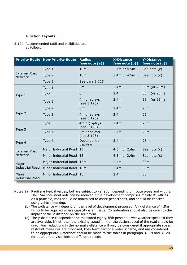
Junction Layouts 3.124 Recommended radii and visibilities are as follows:
4039
Notes (a) Radii are typical values, but are subject to variation depending on route types and widths. The 15m Industrial radii can be reduced if the development comprises mainly B1 offices. As a principle, radii should be minimised to assist pedestrians, and should be checked using vehicle tracking. (b) The x-distance will depend on the level of development proposed. An x-distance of 4.5m will only be required where capacity is an issue. Consideration should also be given to the impact of the x-distance on the built form. (c) The y-distance is dependent on measured eighty-fifth percentile wet weather speeds if they are available. If not, then the existing speed limit or the design speed of the road should be used. Any reductions in the normal y-distance will only be considered if appropriate speed restraint measures are proposed, they form part of a wider scheme, and are considered to be appropriate. Reference should be made to the tables in paragraph 3.119 and 3.120 for appropriate visibilities at different speeds.
Priority Route Non-Priority Route Radius[see note (a)]
X-Distance [see note (b)]
Y-Distance [see note (c)]
External Road Network
Type 1 10m 2.4m or 4.5m See note (c)
Type 2 10m 2.4m or 4.5m See note (c)
Type 3 See para 3.125
Type 1
Type 1 6m 2.4m 33m (or 25m)
Type 2 6m 2.4m 33m (or 25m)
Type 3 4m or splays (see 3.125)
2.4m 33m (or 25m)
Type 2
Type 2 6m 2.4m 25m
Type 3 4m or splays (see 3.125)
2.4m 25m
Type 3
Type 3 4m or) splays (see 3.125)
2.4m 23m
Type 4 4m or splays (see 3.125)
2.4m 23m
Type 4 Type 4 Dependent on tracking
2.4 m 23m
External Road Network
Major Industrial Road 15m 4.5m or 2.4m See note (c)
Minor Industrial Road 15m 4.5m or 2.4m See note (c)
Major Industrial Road
Major Industrial Road 15m 2.4m 33m
Minor Industrial Road 10m 2.4m 33m
Minor Industrial Road
Minor Industrial Road 10m 2.4m 33m
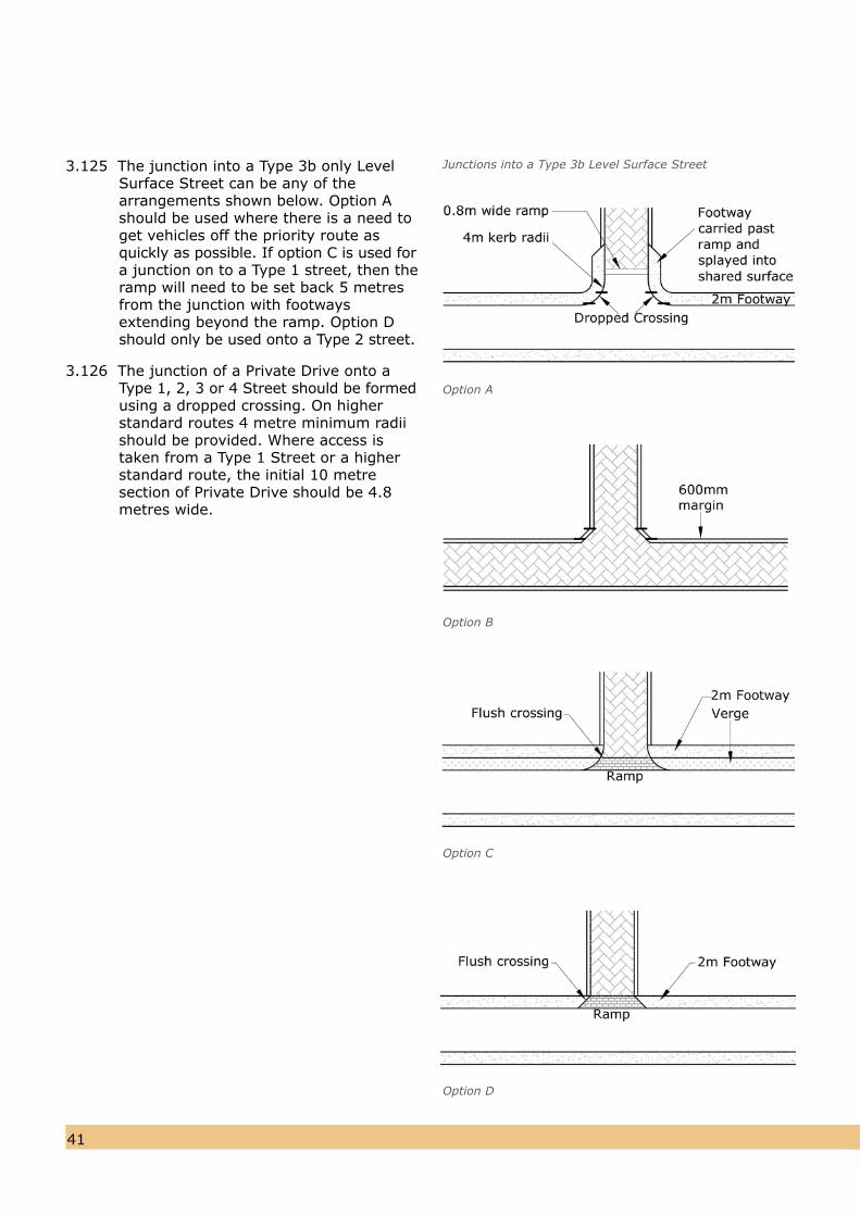
4241
3.125 The junction into a Type 3b only LevelSurface Street can be any of the arrangements shown below. Option Ashould be used where there is a need toget vehicles off the priority route asquickly as possible. If option C is used fora junction on to a Type 1 street, then theramp will need to be set back 5 metresfrom the junction with footways extending beyond the ramp. Option D should only be used onto a Type 2 street.
Junctions into a Type 3b Level Surface Street
3.126 The junction of a Private Drive onto aType 1, 2, 3 or 4 Street should be formedusing a dropped crossing. On higherstandard routes 4 metre minimum radiishould be provided. Where access istaken from a Type 1 Street or a higherstandard route, the initial 10 metresection of Private Drive should be 4.8metres wide.
Option A
Option B
Option C
Option D
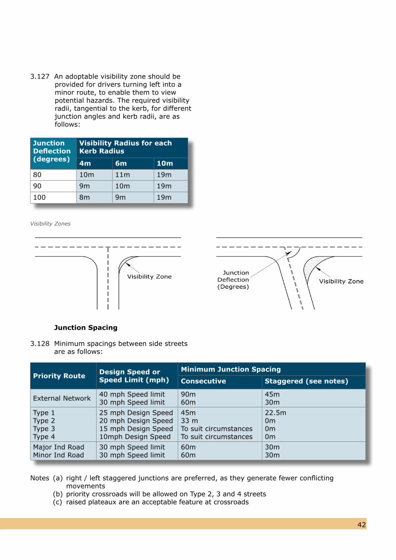
4241
Junction Spacing
3.128 Minimum spacings between side streets are as follows:
Notes (a) right / left staggered junctions are preferred, as they generate fewer conflicting movements (b) priority crossroads will be allowed on Type 2, 3 and 4 streets (c) raised plateaux are an acceptable feature at crossroads
Visibility Zones
Priority Route Design Speed or Speed Limit (mph)
Minimum Junction Spacing
Consecutive Staggered (see notes)
External Network 40 mph Speed limit30 mph Speed limit
90m60m
45m30m
Type 1Type 2Type 3Type 4
25 mph Design Speed20 mph Design Speed 15 mph Design Speed 10mph Design Speed
45m33 mTo suit circumstancesTo suit circumstances
22.5m0m 0m 0m
Major Ind RoadMinor Ind Road
30 mph Speed limit30 mph Speed limit
60m60m
30m30m
3.127 An adoptable visibility zone should beprovided for drivers turning left into aminor route, to enable them to view potential hazards. The required visibility radii, tangential to the kerb, for differentjunction angles and kerb radii, are asfollows:
Junction Deflection (degrees)
Visibility Radius for eachKerb Radius
4m 6m 10m
80 10m 11m 19m
90 9m 10m 19m
100 8m 9m 19m
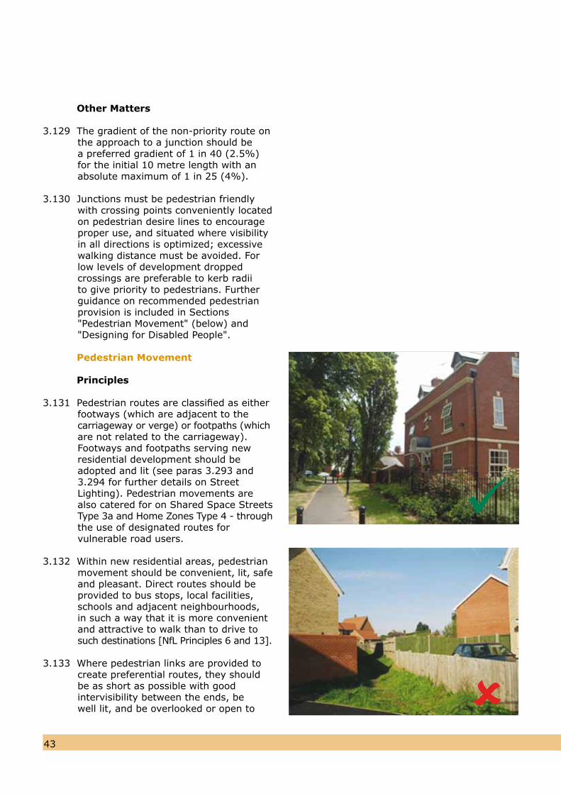
4443
Other Matters
3.129 The gradient of the non-priority route onthe approach to a junction should be a preferred gradient of 1 in 40 (2.5%) for the initial 10 metre length with an absolute maximum of 1 in 25 (4%).
3.130 Junctions must be pedestrian friendly with crossing points conveniently located on pedestrian desire lines to encourage proper use, and situated where visibility in all directions is optimized; excessive walking distance must be avoided. For low levels of development dropped crossings are preferable to kerb radii to give priority to pedestrians. Further guidance on recommended pedestrian provision is included in Sections "Pedestrian Movement" (below) and "Designing for Disabled People".
Pedestrian Movement
Principles
3.131 Pedestrian routes are classified as eitherfootways (which are adjacent to thecarriageway or verge) or footpaths (whichare not related to the carriageway). Footways and footpaths serving new residential development should be adopted and lit (see paras 3.293 and 3.294 for further details on Street Lighting). Pedestrian movements arealso catered for on Shared Space StreetsType 3a and Home Zones Type 4 - throughthe use of designated routes forvulnerable road users.
3.132 Within new residential areas, pedestrian movement should be convenient, lit, safeand pleasant. Direct routes should beprovided to bus stops, local facilities, schools and adjacent neighbourhoods, in such a way that it is more convenientand attractive to walk than to drive tosuch destinations [NfL Principles 6 and 13].
3.133 Where pedestrian links are provided tocreate preferential routes, they should be as short as possible with good intervisibility between the ends, be well lit, and be overlooked or open to
4443
view [NfL Principle 44]. Bollards or similar should be used to prevent the abuse of pedestrian links by motorists, whilst still maintaining access for pedestrians, including wheelchair users.
3.134 As connectivity is a major consideration, the police liaison officer should be consultedon connections and layouts (especially in areas of existing crime and anti-socialbehaviour) to ensure that pressure is notput on the Highway Authority to close throughroutes once the development is occupied.
3.135 Care and attention should be given to the location of street furniture to avoid hazards and to enhance the overall design.
Widths
3.136 Minimum footway (and footpath) widthsshould normally be 2 metres to either side of the carriageway although in certain situations one footway may be acceptable if there is no likelihood of pedestrians utilising a second footway.In such a case, sufficient land will needto be dedicated as adopted verge ifthere is a reasonable likelihood of afootway being needed at any time in the future. Alternatively a minimum grass verge of 1m width or minimum hard margin of 0.6m is required. Theminimum footway width should increaseto 3 metres in areas of identifiably higher levels of pedestrian activity, suchas adjacent to schools, shops, bus stops,etc. Greater widths may be required atspecific points (e.g. around bus shelters).
3.137 For shared Footways/Cycleways see paragraph 3.157.
Gradients and Crossfalls
3.138 The desirable maximum longitudinal section gradient of adoptable footways orfootpaths is 1 in 20 (5%). If this is notachievable then the specific circumstancesshould be discussed with the City Council.
3.139 All footways and footpaths should have a crossfall of 1 in 40 (2.5%) towards the channel.
Vertical Clearance
3.140 A general vertical clearance of 2.6 metres should be provided, with an absolute minimum of 2.1 metres beneath signs. Within 450 mm of the carriageway edgethe full 5.3 metre clearance requirementwill apply, subject to the provisions ofparagraph 3.96.
Steps
3.141 Where flights of steps are included in afootpath, provision should be made for a complementary ramped route (see paras 3.170 - 3.173 for the design of ramps). If a ramp cannot be accommodated within the space available, then thesteps should be designed to cater for as many users as possible.
3.142 Steps shall have a constant rise of between 100mm minimum and 150mmmaximum with a preferred height of130mm. Open risers are not permitted. Treads should be 300mm wide (minimum 280mm), non-slip and marked with a non-slip edging at the head of each flight. The dimensions must be such that the product of Tread plus twice the riser is between 550 and 600mm. Nosings should be splayed or rounded to a 6mm radius. There should be a minimum of 3 steps in a flight and a maximum of 12, with resting places between successive flights. Resting places should be at least 1200mm long, preferably 1800mm.
3.143 Handrails must be provided, should besmooth and continuous where there is more than one flight of steps and should be terminated no less than 300mm past the end of the flight and ‘closed’ to the stair wall. Handrails should be set at a height of 900-1000mm above the tread of each step and should be round in section, between 45-50mm in diameter and with a 45mm gap to the wall. Handrails should be provided on both sides, a minimum of 1200mm apart and a maximum of 1800mm apart.
3.144 Non slip corduroy paving should be provided at the top and bottom of steps.
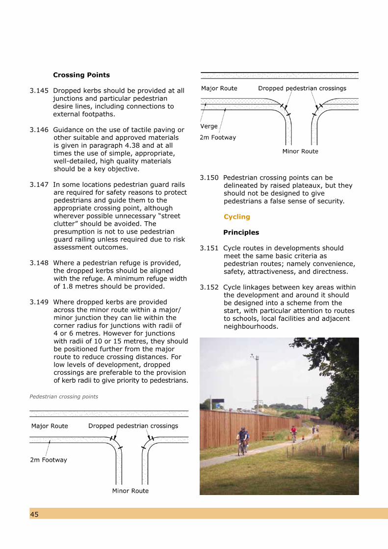
Crossing Points
3.145 Dropped kerbs should be provided at all junctions and particular pedestrian desire lines, including connections to external footpaths.
3.146 Guidance on the use of tactile paving orother suitable and approved materials is given in paragraph 4.38 and at all times the use of simple, appropriate, well-detailed, high quality materials should be a key objective.
3.147 In some locations pedestrian guard railsare required for safety reasons to protectpedestrians and guide them to the appropriate crossing point, although wherever possible unnecessary “street clutter” should be avoided. The presumption is not to use pedestrian guard railing unless required due to riskassessment outcomes.
3.148 Where a pedestrian refuge is provided,the dropped kerbs should be aligned with the refuge. A minimum refuge widthof 1.8 metres should be provided.
3.149 Where dropped kerbs are provided across the minor route within a major/minor junction they can lie within thecorner radius for junctions with radii of4 or 6 metres. However for junctions with radii of 10 or 15 metres, they shouldbe positioned further from the major route to reduce crossing distances. Forlow levels of development, droppedcrossings are preferable to the provisionof kerb radii to give priority to pedestrians.
Pedestrian crossing points
3.150 Pedestrian crossing points can bedelineated by raised plateaux, but theyshould not be designed to give pedestrians a false sense of security.
Cycling
Principles
3.151 Cycle routes in developments shouldmeet the same basic criteria as pedestrian routes; namely convenience, safety, attractiveness, and directness.
3.152 Cycle linkages between key areas withinthe development and around it should be designed into a scheme from thestart, with particular attention to routesto schools, local facilities and adjacentneighbourhoods.
4645
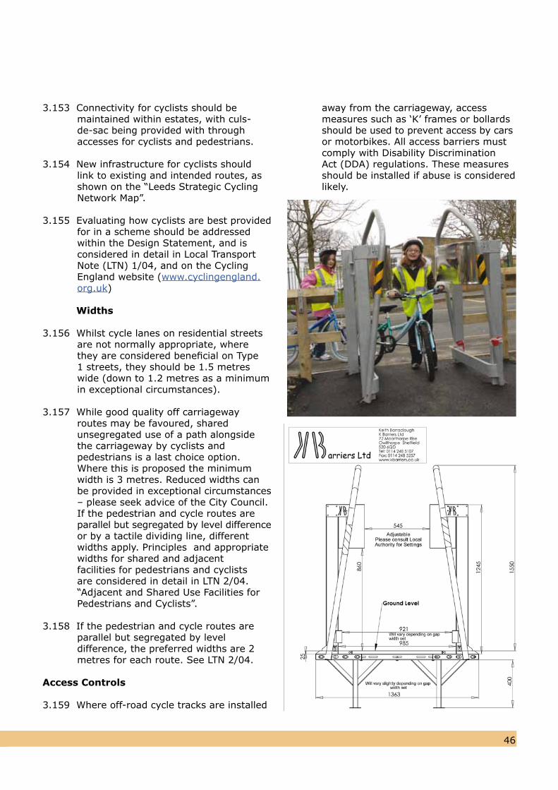
4645
3.153 Connectivity for cyclists should bemaintained within estates, with culs-de-sac being provided with through accesses for cyclists and pedestrians.
3.154 New infrastructure for cyclists should link to existing and intended routes, asshown on the “Leeds Strategic CyclingNetwork Map”.
3.155 Evaluating how cyclists are best providedfor in a scheme should be addressed within the Design Statement, and isconsidered in detail in Local TransportNote (LTN) 1/04, and on the CyclingEngland website (www.cyclingengland.org.uk)
Widths
3.156 Whilst cycle lanes on residential streets are not normally appropriate, where they are considered beneficial on Type 1 streets, they should be 1.5 metres wide (down to 1.2 metres as a minimum in exceptional circumstances).
3.157 While good quality off carriageway routes may be favoured, shared unsegregated use of a path alongside the carriageway by cyclists and pedestrians is a last choice option. Where this is proposed the minimum width is 3 metres. Reduced widths can be provided in exceptional circumstances – please seek advice of the City Council. If the pedestrian and cycle routes areparallel but segregated by level differenceor by a tactile dividing line, different widths apply. Principles and appropriate widths for shared and adjacent facilities for pedestrians and cyclists are considered in detail in LTN 2/04. “Adjacent and Shared Use Facilities forPedestrians and Cyclists”.
3.158 If the pedestrian and cycle routes areparallel but segregated by level difference, the preferred widths are 2 metres for each route. See LTN 2/04.
Access Controls
3.159 Where off-road cycle tracks are installed
away from the carriageway, access measures such as ‘K’ frames or bollardsshould be used to prevent access by carsor motorbikes. All access barriers mustcomply with Disability Discrimination Act (DDA) regulations. These measuresshould be installed if abuse is consideredlikely.
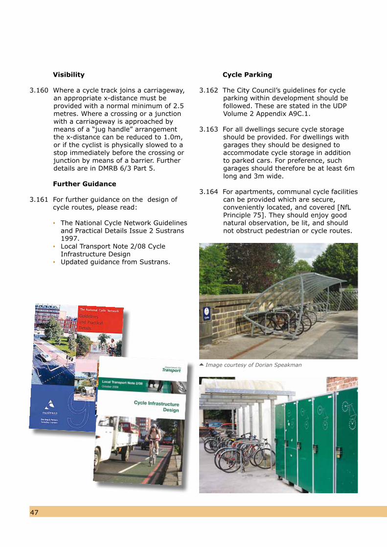
4847
Visibility
3.160 Where a cycle track joins a carriageway, an appropriate x-distance must be provided with a normal minimum of 2.5 metres. Where a crossing or a junction with a carriageway is approached by means of a “jug handle” arrangement the x-distance can be reduced to 1.0m, or if the cyclist is physically slowed to astop immediately before the crossing orjunction by means of a barrier. Further details are in DMRB 6/3 Part 5.
Further Guidance
3.161 For further guidance on the design of cycle routes, please read: ▪ The National Cycle Network Guidelines and Practical Details Issue 2 Sustrans 1997. ▪ Local Transport Note 2/08 Cycle Infrastructure Design ▪ Updated guidance from Sustrans.
Cycle Parking
3.162 The City Council’s guidelines for cycleparking within development should befollowed. These are stated in the UDPVolume 2 Appendix A9C.1.
3.163 For all dwellings secure cycle storage
should be provided. For dwellings withgarages they should be designed toaccommodate cycle storage in addition to parked cars. For preference, suchgarages should therefore be at least 6mlong and 3m wide.
3.164 For apartments, communal cycle facilitiescan be provided which are secure,conveniently located, and covered [NfL Principle 75]. They should enjoy good natural observation, be lit, and should not obstruct pedestrian or cycle routes.
Image courtesy of Dorian Speakman
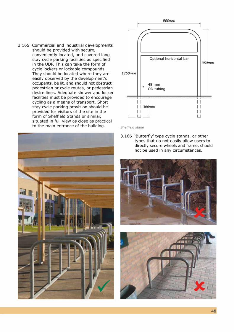
4847
3.165 Commercial and industrial developments should be provided with secure, conveniently located, and covered long stay cycle parking facilities as specified in the UDP. This can take the form of cycle lockers or lockable compounds. They should be located where they are easily observed by the development’s occupants, be lit, and should not obstructpedestrian or cycle routes, or pedestrian desire lines. Adequate shower and locker facilities must be provided to encourage cycling as a means of transport. Short stay cycle parking provision should be provided for visitors of the site in the form of Sheffield Stands or similar, situated in full view as close as practical to the main entrance of the building. Sheffield stand
3.166 ‘Butterfly’ type cycle stands, or other types that do not easily allow users to directly secure wheels and frame, should not be used in any circumstances.
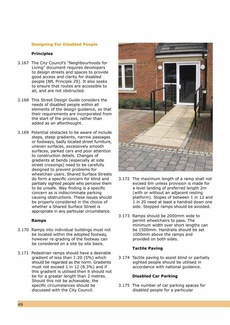
5049
Designing For Disabled People
Principles
3.167 The City Council’s “Neighbourhoods for Living” document requires developers to design streets and spaces to provide good access and clarity for disabled people [NfL Principle 29]. It also seeks to ensure that routes are accessible toall, and are not obstructed.
3.168 This Street Design Guide considers the needs of disabled people within all elements of the design guidance, so thattheir requirements are incorporated fromthe start of the process, rather thanadded as an afterthought.
3.169 Potential obstacles to be aware of includesteps, steep gradients, narrow passagesor footways, badly located street furniture,uneven surfaces, excessively smoothsurfaces, parked cars and poor attentionto construction details. Changes ofgradients at bends (especially at sidestreet crossings) need to be carefullydesigned to prevent problems forwheelchair users. Shared Surface Streetsdo form a specific concern for blind andpartially sighted people who perceive themto be unsafe. Way finding is a specificconcern as is indiscriminate parkingcausing obstructions. These issues shouldbe properly considered in the choice ofwhether a Shared Surface Street isappropriate in any particular circumstance.
Ramps
3.170 Ramps into individual buildings must notbe located within the adopted footway, however re-grading of the footway can be considered on a site by site basis.
3.171 Pedestrian ramps should have a desirablegradient of less than 1:20 (5%) whichshould be regarded as the norm. Gradients must not exceed 1 in 12 (8.3%) and if this gradient is utilised then it should not be for a greater length than 2 metres.Should this not be achievable, the specific circumstances should be discussed with the City Council.
3.172 The maximum length of a ramp shall notexceed 6m unless provision is made fora level landing of preferred length 2m(with or without an adjacent resting platform). Slopes of between 1 in 12 and1 in 20 need at least a handrail down oneside. Stepped ramps should be avoided.
3.173 Ramps should be 2000mm wide topermit wheelchairs to pass. The minimum width over short lengths canbe 1500mm. Handrails should be set1000mm above the ramps and provided on both sides.
Tactile Paving
3.174 Tactile paving to assist blind or partiallysighted people should be utilised in accordance with national guidance.
Disabled Car Parking
3.175 The number of car parking spaces for disabled people for a particular
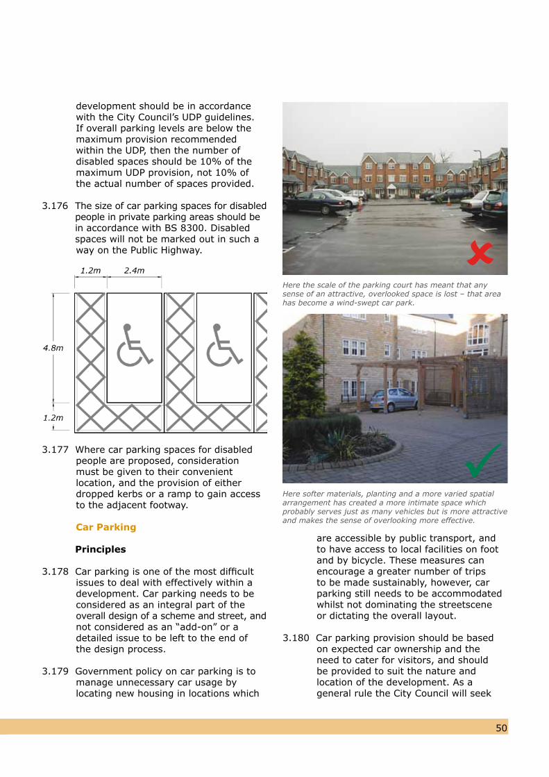
5049
development should be in accordance with the City Council’s UDP guidelines. If overall parking levels are below the maximum provision recommended within the UDP, then the number of disabled spaces should be 10% of the maximum UDP provision, not 10% of the actual number of spaces provided.
3.176 The size of car parking spaces for disabled people in private parking areas should be in accordance with BS 8300. Disabled spaces will not be marked out in such a
way on the Public Highway.
3.177 Where car parking spaces for disabledpeople are proposed, consideration must be given to their convenient location, and the provision of either dropped kerbs or a ramp to gain accessto the adjacent footway.
Car Parking
Principles
3.178 Car parking is one of the most difficultissues to deal with effectively within adevelopment. Car parking needs to beconsidered as an integral part of theoverall design of a scheme and street, andnot considered as an “add-on” or adetailed issue to be left to the end ofthe design process.
3.179 Government policy on car parking is tomanage unnecessary car usage by locating new housing in locations which
are accessible by public transport, and to have access to local facilities on foot and by bicycle. These measures can encourage a greater number of trips to be made sustainably, however, car parking still needs to be accommodated whilst not dominating the streetscene or dictating the overall layout.
3.180 Car parking provision should be basedon expected car ownership and the need to cater for visitors, and should be provided to suit the nature and location of the development. As a general rule the City Council will seek
Here softer materials, planting and a more varied spatial arrangement has created a more intimate space which probably serves just as many vehicles but is more attractive and makes the sense of overlooking more effective.
Here the scale of the parking court has meant that anysense of an attractive, overlooked space is lost – that areahas become a wind-swept car park.
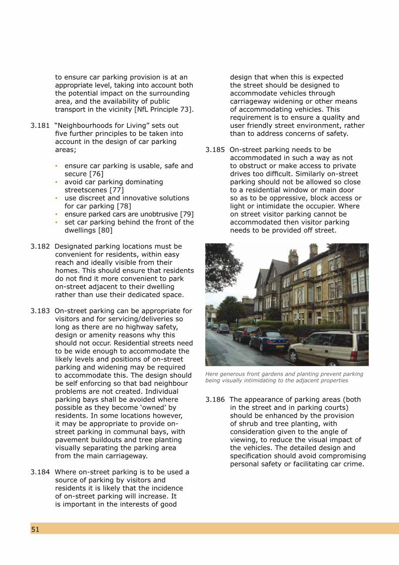
5251
to ensure car parking provision is at anappropriate level, taking into account boththe potential impact on the surroundingarea, and the availability of publictransport in the vicinity [NfL Principle 73].
3.181 “Neighbourhoods for Living” sets outfive further principles to be taken intoaccount in the design of car parkingareas;
▪ ensure car parking is usable, safe and secure [76]▪ avoid car parking dominating streetscenes [77]▪ use discreet and innovative solutions for car parking [78]▪ ensure parked cars are unobtrusive [79]▪ set car parking behind the front of the dwellings [80]
3.182 Designated parking locations must beconvenient for residents, within easyreach and ideally visible from their homes. This should ensure that residents do not find it more convenient to park on-street adjacent to their dwelling rather than use their dedicated space.
3.183 On-street parking can be appropriate forvisitors and for servicing/deliveries solong as there are no highway safety, design or amenity reasons why thisshould not occur. Residential streets needto be wide enough to accommodate thelikely levels and positions of on-streetparking and widening may be required to accommodate this. The design should be self enforcing so that bad neighbour problems are not created. Individual parking bays shall be avoided where possible as they become ‘owned’ by residents. In some locations however, it may be appropriate to provide on-street parking in communal bays, withpavement buildouts and tree planting visually separating the parking areafrom the main carriageway.
3.184 Where on-street parking is to be used a source of parking by visitors and residents it is likely that the incidence of on-street parking will increase. It is important in the interests of good
design that when this is expected the street should be designed to accommodate vehicles through carriageway widening or other means of accommodating vehicles. This requirement is to ensure a quality and user friendly street environment, rather than to address concerns of safety.
3.185 On-street parking needs to be accommodated in such a way as not to obstruct or make access to private drives too difficult. Similarly on-street parking should not be allowed so close to a residential window or main door so as to be oppressive, block access or light or intimidate the occupier. Where on street visitor parking cannot be accommodated then visitor parking needs to be provided off street.
3.186 The appearance of parking areas (both in the street and in parking courts) should be enhanced by the provision of shrub and tree planting, with consideration given to the angle of viewing, to reduce the visual impact of the vehicles. The detailed design and specification should avoid compromising personal safety or facilitating car crime.
Here generous front gardens and planting prevent parking being visually intimidating to the adjacent properties
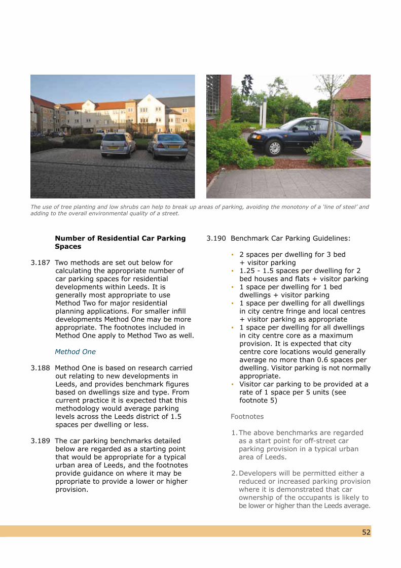
5251
Number of Residential Car Parking Spaces
3.187 Two methods are set out below for calculating the appropriate number ofcar parking spaces for residential developments within Leeds. It is generally most appropriate to use Method Two for major residential planning applications. For smaller infill developments Method One may be moreappropriate. The footnotes included inMethod One apply to Method Two as well.
Method One
3.188 Method One is based on research carriedout relating to new developments in Leeds, and provides benchmark figures based on dwellings size and type. From current practice it is expected that thismethodology would average parkinglevels across the Leeds district of 1.5spaces per dwelling or less.
3.189 The car parking benchmarks detailed below are regarded as a starting pointthat would be appropriate for a typicalurban area of Leeds, and the footnotesprovide guidance on where it may be ppropriate to provide a lower or higherprovision.
3.190 Benchmark Car Parking Guidelines:
▪ 2 spaces per dwelling for 3 bed + visitor parking▪ 1.25 - 1.5 spaces per dwelling for 2 bed houses and flats + visitor parking▪ 1 space per dwelling for 1 bed dwellings + visitor parking▪ 1 space per dwelling for all dwellings in city centre fringe and local centres + visitor parking as appropriate▪ 1 space per dwelling for all dwellings in city centre core as a maximum provision. It is expected that city centre core locations would generally average no more than 0.6 spaces per dwelling. Visitor parking is not normally appropriate.▪ Visitor car parking to be provided at a rate of 1 space per 5 units (see footnote 5)
Footnotes
1. The above benchmarks are regarded as a start point for off-street car parking provision in a typical urban area of Leeds.
2. Developers will be permitted either a reduced or increased parking provision where it is demonstrated that car ownership of the occupants is likely to be lower or higher than the Leeds average.
The use of tree planting and low shrubs can help to break up areas of parking, avoiding the monotony of a ‘line of steel’ andadding to the overall environmental quality of a street.
3. Residential Car Parking Researchpublished by the Department of Communities and Local Government (DCLG) in May 2007 suggests thatmajor factors influencing car ownership are dwelling size, type andtenure. The location, availability andquality of public transport, availability of on-street parking and specific measures promoted to reduce carownership eg car clubs, may also influence car ownership. The allocationof spaces to individual dwellings caninfluence the efficiency of car parking provision. Highway Officers may requirechanges to a Developer’s parking provision based upon these factors.Where either the Developer or HighwayOfficer requires a different parkingprovision to that stated above, thejustification should be based uponlikely car ownership and allocation ofparking spaces, not car usage. Thefollowing factors need to be considered:
Type of Housing - i.e. houses, flats, rented, affordable (note: the revised appendix A9A of the UDP provides separate guidance for Student and Retirement and Sheltered Housing).
Location - The above benchmarks are regarded as a starting point for off-street car parking provision in a typical urban area of Leeds as stated. Therefore the types of locations thatcould be considered differently include: city centre, city centre fringe,S2 town and district centres, beyondthe outer ring road, outer-lying/ruralsettlements. The convenience of alocation to facilities and employment also needs to be considered, i.e employment centres, shopping, banking, schools, and health andleisure facilities.
Availability and Quality of Public Transport – consideration needs to be given to the proximity of bus/train stops, variety of services and frequency, capacity and journey times when compared to an equivalent car journey time for all journey types.
Type of Potential Occupier – i.e. age, income, families, professionals.
Availability of On-Street Parking – Consideration needs to be given to whether there are restrictions that prevent convenient opportunities to park on street, i.e. parking restrictions (TROs) and existing competing demand for on-street parking.
(The above list of factors is notexhaustive)
4. Where a property is provided with allocated parking, at least one 'open' or surface car parking space is required per unit in all the cases stated above, i.e.where a residential unit is considered to require only one car parking space, that space should not be a garage (see also footnote 9).
5. Where a proposal includes communalparking areas a suitable condition willbe used to ensure that parking spacesare not sold on to individual plots/units.A further condition is required to ensure that visitor and disabled persons' parking spaces remain so in perpetuity and cannot fall into individual ownership. Where visitor parking is provided off-street, it should be freely accessible ie not be enclosed behind private gates, etc. A Section 106 Agreement may be required to control this issue.
6. Where parking is remote from the dwelling but allocated the applicant will be asked to identify all parking spaces with its associated plot/unit number. The parking spaces will then be conditioned to be retained by the dwellings identified.
7. Where housing layouts are designed on Type 2 or 3 streets the Method One visitor parking requirement can be provided on street if the carriageway is a minimum of 5.5m wide and suitable on street parking spaces can be identified that do not impede pedestrians, access to drives/
5453
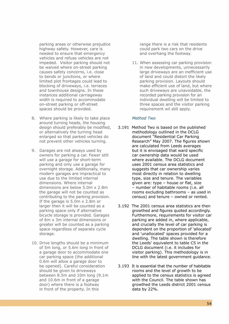
parking areas or otherwise prejudice highway safety. However, care is needed to ensure that emergency vehicles and refuse vehicles are not impeded. Visitor parking should not be waived where on-street parking causes safety concerns, i.e. close to bends or junctions, or where limited plot frontages could lead to blocking of driveways, i.e. terraces and townhouse designs. In these instances additional carriageway width is required to accommodate on-street parking or off-street spaces should be provided.
8. Where parking is likely to take placearound turning heads, the housing design should preferably be modified, or alternatively the turning head enlarged so that parked vehicles do not prevent other vehicles turning.
9. Garages are not always used by owners for parking a car. Fewer stillwill use a garage for short-term parking and only use a garage for overnight storage. Additionally, manymodern garages are impractical touse due to the limited internal dimensions. Where internal dimensions are below 5.0m x 2.8m the garage will not be counted ascontributing to the parking provision.If the garage is 5.0m x 2.8m or larger then it will be counted as a parking space only if alternative bicycle storage is provided. Garages of 6m x 3m internal dimensions orgreater will be counted as a parkingspace regardless of separate cyclestorage.
10. Drive lengths should be a minimum of 5m long, or 5.6m long in front of a garage door to accommodate one car parking space (the additional 0.6m will allow a garage door to be opened). Careful consideration should be given to driveways between 8.5m and 10m long (9.1m and 10.6m in front of a garage door) where there is a footway in front of the property. In this
range there is a risk that residents could park two cars on the drive and overhang the footway.
11. When assessing car parking provisionin new developments, unnecessarily large driveways are an inefficient useof land and could distort the likelyparking provision. Layouts should make efficient use of land, but wheresuch driveways are unavoidable, therecorded parking provision for anindividual dwelling will be limited tothree spaces and the visitor parking requirement wil still apply.
Method Two
3.191 Method Two is based on the published methodology outlined in the DCLG document “Residential Car Parking Research” May 2007. The figures shown are calculated from Leeds averages but it is envisaged that ward specific car ownership data would be used where available. The DCLG document uses 2001 census area statistics and suggests that car ownership varies most directly in relation to dwelling type, size and tenure. The variables given are: type – house or flat, size – number of habitable rooms (i.e. all rooms excluding bathrooms – as used in census) and tenure – owned or rented.
3.192 The 2001 census area statistics are thengrowthed and figures quoted accordingly. Furthermore, requirements for visitor car parking are added in, where applicable,and crucially the level of car parking isdependent on the proportion of 'allocated'and 'unallocated' spaces provided for adwelling. The table shown is thereforethe Leeds’ equivalent to table C5 in theDCLG document (i.e. it includes forvisitor parking). This methodology is inline with the latest government guidance.
3.193 It is essential that the number of habitablerooms and the level of growth to beapplied to the census statistics is agreedwith the Council. The table shown hasgrowthed the Leeds district 2001 censusdata by 22%.
5453
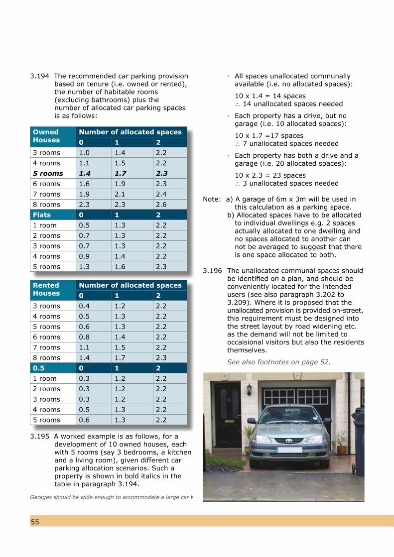
5655
3.195 A worked example is as follows, for adevelopment of 10 owned houses, eachwith 5 rooms (say 3 bedrooms, a kitchenand a living room), given different carparking allocation scenarios. Such aproperty is shown in bold italics in thetable in paragraph 3.194.
▪ All spaces unallocated communally available (i.e. no allocated spaces):
10 x 1.4 = 14 spaces ∴ 14 unallocated spaces needed
▪ Each property has a drive, but no garage (i.e. 10 allocated spaces):
10 x 1.7 =17 spaces ∴ 7 unallocated spaces needed
▪ Each property has both a drive and a garage (i.e. 20 allocated spaces):
10 x 2.3 = 23 spaces ∴ 3 unallocated spaces needed
Note: a) A garage of 6m x 3m will be used in this calculation as a parking space.b) Allocated spaces have to be allocated to individual dwellings e.g. 2 spaces actually allocated to one dwelling and no spaces allocated to another can not be averaged to suggest that there is one space allocated to both.
3.196 The unallocated communal spaces should be identified on a plan, and should be
conveniently located for the intendedusers (see also paragraph 3.202 to3.209). Where it is proposed that theunallocated provision is provided on-street,this requirement must be designed into the street layout by road widening etc.as the demand will not be limited tooccaisional visitors but also the residentsthemselves.
See also footnotes on page 52.
3.194 The recommended car parking provisionbased on tenure (i.e. owned or rented),the number of habitable rooms (excluding bathrooms) plus thenumber of allocated car parking spacesis as follows:
Garages should be wide enough to accommodate a large car
Owned Houses
Number of allocated spaces
0 1 2
3 rooms 1.0 1.4 2.2
4 rooms 1.1 1.5 2.2
5 rooms 1.4 1.7 2.3
6 rooms 1.6 1.9 2.3
7 rooms 1.9 2.1 2.4
8 rooms 2.3 2.3 2.6
Flats 0 1 2
1 room 0.5 1.3 2.2
2 rooms 0.7 1.3 2.2
3 rooms 0.7 1.3 2.2
4 rooms 0.9 1.4 2.2
5 rooms 1.3 1.6 2.3
Rented Houses
Number of allocated spaces
0 1 2
3 rooms 0.4 1.2 2.2
4 rooms 0.5 1.3 2.2
5 rooms 0.6 1.3 2.2
6 rooms 0.8 1.4 2.2
7 rooms 1.1 1.5 2.2
8 rooms 1.4 1.7 2.3
0.5 0 1 2
1 room 0.3 1.2 2.2
2 rooms 0.3 1.2 2.2
3 rooms 0.3 1.2 2.2
4 rooms 0.5 1.3 2.2
5 rooms 0.6 1.3 2.2
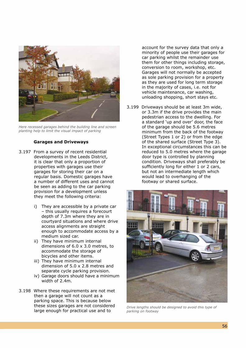
5655
Garages and Driveways
3.197 From a survey of recent residential developments in the Leeds District, it is clear that only a proportion of properties with garages use their garages for storing their car on a regular basis. Domestic garages have a number of different uses and cannot be seen as adding to the car parking provision for a development unless they meet the following criteria:
i) They are accessible by a private car – this usually requires a forecourt depth of 7.3m where they are in courtyard situations and where drive access alignments are straight enough to accommodate access by a medium sized car.ii) They have minimum internal dimensions of 6.0 x 3.0 metres, to accommodate the storage of bicycles and other items.iii) They have minimum internal dimension of 5.0 x 2.8 metres and separate cycle parking provision.iv) Garage doors should have a minimum width of 2.4m.
3.198 Where these requirements are not metthen a garage will not count as a parking space. This is because below these sizes garages are not considered large enough for practical use and to
account for the survey data that only a minority of people use their garages for car parking whilst the remainder use them for other things including storage, conversion to room, workshop, etc. Garages will not normally be accepted as sole parking provision for a property as they are used for long term storage in the majority of cases, i.e. not for vehicle maintenance, car washing, unloading shopping, short stays etc.
3.199 Driveways should be at least 3m wide,or 3.3m if the drive provides the main pedestrian access to the dwelling. For a standard ‘up and over’ door, the face of the garage should be 5.6 metres minimum from the back of the footway (Street Types 1 or 2) or from the edge of the shared surface (Street Type 3).In exceptional circumstances this can bereduced to 5.0 metres where the garage door type is controlled by planning condition. Driveways shall preferably besufficiently long for either 1 or 2 cars,but not an intermediate length whichwould lead to overhanging of the footway or shared surface.
Here recessed garages behind the building line and screen planting help to limit the visual impact of parking
Drive lengths should be designed to avoid this type ofparking on footway
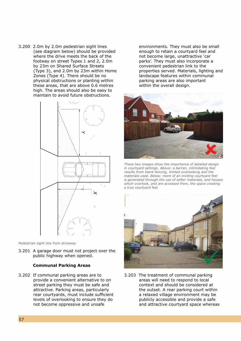
5857
3.200 2.0m by 2.0m pedestrian sight lines (see diagram below) should be provided where the drive meets the back of the footway on street Types 1 and 2, 2.0m by 23m on Shared Surface Streets (Type 3), and 2.0m by 23m within Home Zones (Type 4). There should be no physical obstructions or planting within these areas, that are above 0.6 metres high. The areas should also be easy to maintain to avoid future obstructions.
3.201 A garage door must not project over the public highway when opened.
Communal Parking Areas
3.202 If communal parking areas are to provide a convenient alternative to on street parking they must be safe and attractive. Parking areas, particularly rear courtyards, must include sufficient levels of overlooking to ensure they donot become oppressive and unsafe
environments. They must also be small enough to retain a courtyard feel and not become large, unattractive ‘car parks’. They must also incorporate aconvenient pedestrian link to the properties served. Materials, lighting and landscape features within communalparking areas are also important within the overall design.
3.203 The treatment of communal parking areas will need to respond to local context and should be considered at the outset. A rear parking court within a relaxed village environment may be publicly accessible and provide a safe and attractive courtyard space whereas
Pedestrian sight line from driveway
These two images show the importance of detailed design in courtyard settings. Above: a barren, intimidating feel results from blank fencing, limited overlooking and the materials used. Below: more of an inviting courtyard feelis generated through the use of softer materials, and houseswhich overlook, and are accessed from, the space creatinga true courtyard feel.
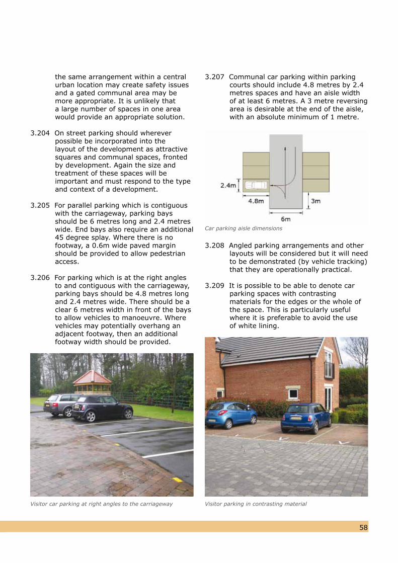
5857
the same arrangement within a central urban location may create safety issues and a gated communal area may be more appropriate. It is unlikely that a large number of spaces in one area would provide an appropriate solution.
3.204 On street parking should wherever possible be incorporated into thelayout of the development as attractivesquares and communal spaces, fronted by development. Again the size and treatment of these spaces will be important and must respond to the typeand context of a development.
3.205 For parallel parking which is contiguous with the carriageway, parking bays should be 6 metres long and 2.4 metreswide. End bays also require an additional45 degree splay. Where there is nofootway, a 0.6m wide paved marginshould be provided to allow pedestrianaccess.
3.206 For parking which is at the right angles to and contiguous with the carriageway, parking bays should be 4.8 metres long and 2.4 metres wide. There should be a clear 6 metres width in front of the bays to allow vehicles to manoeuvre. Where vehicles may potentially overhang an adjacent footway, then an additional footway width should be provided.
Visitor car parking at right angles to the carriageway
3.207 Communal car parking within parking courts should include 4.8 metres by 2.4 metres spaces and have an aisle width of at least 6 metres. A 3 metre reversing area is desirable at the end of the aisle, with an absolute minimum of 1 metre.
Car parking aisle dimensions
3.208 Angled parking arrangements and otherlayouts will be considered but it will need to be demonstrated (by vehicle tracking) that they are operationally practical.
3.209 It is possible to be able to denote carparking spaces with contrasting materials for the edges or the whole of the space. This is particularly usefulwhere it is preferable to avoid the useof white lining.
Visitor parking in contrasting material
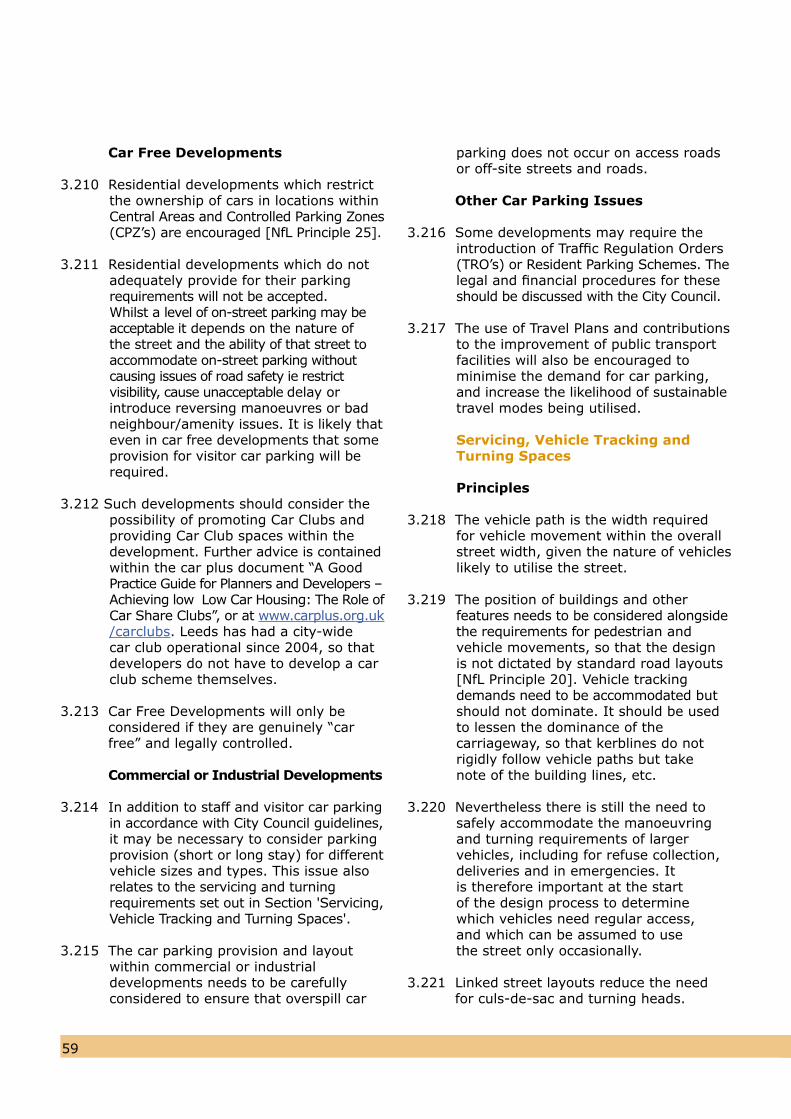
6059
Car Free Developments
3.210 Residential developments which restrict the ownership of cars in locations withinCentral Areas and Controlled Parking Zones(CPZ’s) are encouraged [NfL Principle 25].
3.211 Residential developments which do notadequately provide for their parking requirements will not be accepted. Whilst a level of on-street parking may be acceptable it depends on the nature of the street and the ability of that street to accommodate on-street parking without causing issues of road safety ie restrict visibility, cause unacceptable delay or introduce reversing manoeuvres or badneighbour/amenity issues. It is likely thateven in car free developments that someprovision for visitor car parking will berequired.
3.212 Such developments should consider the possibility of promoting Car Clubs andproviding Car Club spaces within thedevelopment. Further advice is containedwithin the car plus document “A GoodPractice Guide for Planners and Developers –Achieving low Low Car Housing: The Role ofCar Share Clubs”, or at www.carplus.org.uk/carclubs. Leeds has had a city-wide car club operational since 2004, so that developers do not have to develop a carclub scheme themselves.
3.213 Car Free Developments will only be considered if they are genuinely “car free” and legally controlled.
Commercial or Industrial Developments
3.214 In addition to staff and visitor car parkingin accordance with City Council guidelines,it may be necessary to consider parkingprovision (short or long stay) for differentvehicle sizes and types. This issue alsorelates to the servicing and turning requirements set out in Section 'Servicing, Vehicle Tracking and Turning Spaces'.
3.215 The car parking provision and layout within commercial or industrial developments needs to be carefully considered to ensure that overspill car
parking does not occur on access roadsor off-site streets and roads.
Other Car Parking Issues
3.216 Some developments may require theintroduction of Traffic Regulation Orders(TRO’s) or Resident Parking Schemes. Thelegal and financial procedures for theseshould be discussed with the City Council.
3.217 The use of Travel Plans and contributions to the improvement of public transport facilities will also be encouraged tominimise the demand for car parking, and increase the likelihood of sustainable travel modes being utilised.
Servicing, Vehicle Tracking andTurning Spaces
Principles
3.218 The vehicle path is the width requiredfor vehicle movement within the overallstreet width, given the nature of vehicleslikely to utilise the street.
3.219 The position of buildings and other features needs to be considered alongside the requirements for pedestrian and vehicle movements, so that the design is not dictated by standard road layouts [NfL Principle 20]. Vehicle tracking demands need to be accommodated butshould not dominate. It should be usedto lessen the dominance of the carriageway, so that kerblines do notrigidly follow vehicle paths but take note of the building lines, etc.
3.220 Nevertheless there is still the need tosafely accommodate the manoeuvring and turning requirements of larger vehicles, including for refuse collection, deliveries and in emergencies. It is therefore important at the start of the design process to determine which vehicles need regular access, and which can be assumed to use the street only occasionally.
3.221 Linked street layouts reduce the need for culs-de-sac and turning heads.
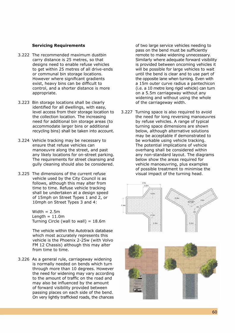
6059
Servicing Requirements
3.222 The recommended maximum dustbincarry distance is 25 metres, so thatdesigns need to enable refuse vehicles to get within 25 metres of all drive-ends or communal bin storage locations.However where significant gradientsexist, heavy bins can be difficult tocontrol, and a shorter distance is moreappropriate.
3.223 Bin storage locations shall be clearly identified for all dwellings, with easy,level access from their storage location tothe collection location. The increasing need for additional bin storage areas (toaccommodate larger bins or additionalrecycling bins) shall be taken into account.
3.224 Vehicle tracking may be necessary toensure that refuse vehicles canmanoeuvre along the street, and pastany likely locations for on-street parking.The requirements for street cleansing andgully cleaning should also be considered.
3.225 The dimensions of the current refuse vehicle used by the City Council is as follows, although this may alter from time to time. Refuse vehicle tracking shall be undertaken at a design speed of 15mph on Street Types 1 and 2, or10mph on Street Types 3 and 4:
Width = 2.5m Length = 11.0m Turning Circle (wall to wall) = 18.6m
The vehicle within the Autotrack database which most accurately represents thisvehicle is the Phoenix 2-25w (with VolvoFM 12 Chassis) although this may alterfrom time to time.
3.226 As a general rule, carriageway widening is normally needed on bends which turnthrough more than 10 degrees. However the need for widening may vary accordingto the amount of traffic on the road andmay also be influenced by the amount of forward visibility provided between passing places on each side of the bend. On very lightly trafficked roads, the chances
of two large service vehicles needing to pass on the bend must be sufficiently remote to make widening unnecessary. Similarly where adequate forward visibility is provided between oncoming vehicles it will be possible for large vehicles to wait until the bend is clear and to use part of the opposite lane when turning. Even with a 15m outer curve radius a pantechicon (i.e. a 10 metre long rigid vehicle) can turnon a 5.5m carriageway without any widening and without using the wholeof the carriageway width.
3.227 Turning space is also required to avoid
the need for long reversing manoeuvres by refuse vehicles. A range of typical turning space dimensions are shown below, although alternative solutions may be acceptable if demonstrated to be workable using vehicle tracking. The potential implications of vehicle overhang shall be considered within any non-standard layout. The diagrams below show the areas required for vehicle manoeuvring, plus examples of possible treatment to minimise the visual impact of the turning head.
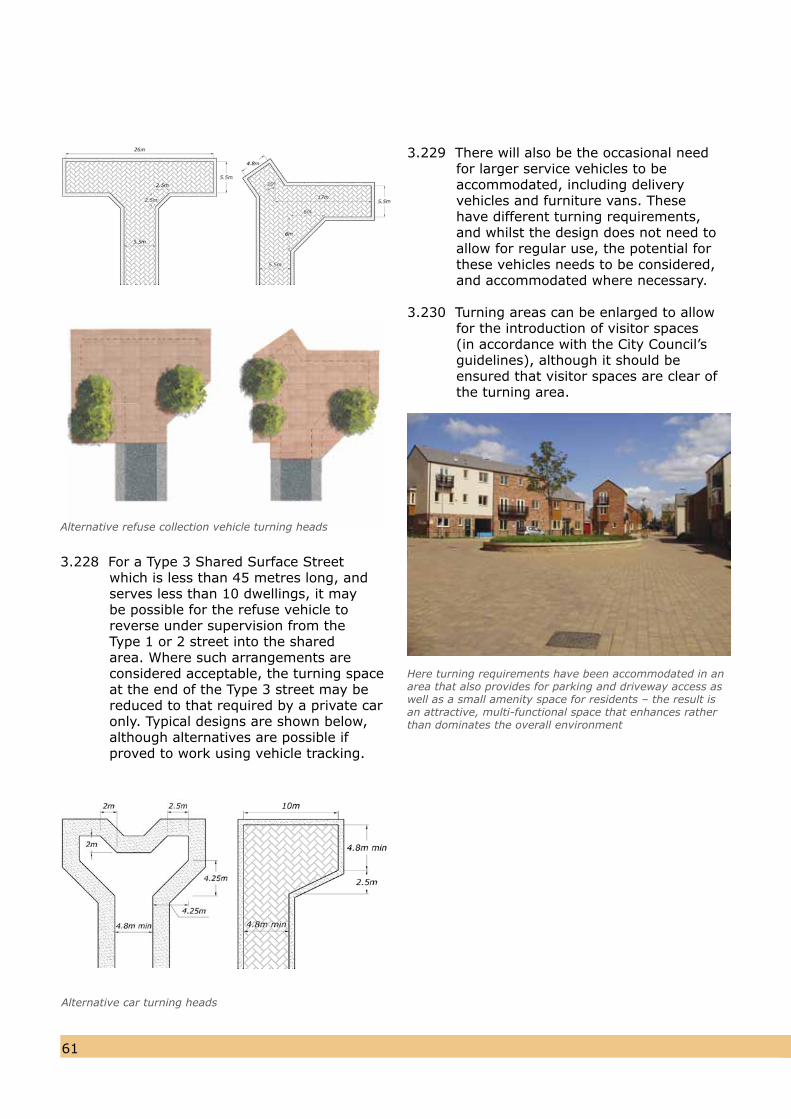
6261
3.228 For a Type 3 Shared Surface Street which is less than 45 metres long, andserves less than 10 dwellings, it may be possible for the refuse vehicle to reverse under supervision from the Type 1 or 2 street into the shared area. Where such arrangements are considered acceptable, the turning space at the end of the Type 3 street may be reduced to that required by a private car only. Typical designs are shown below, although alternatives are possible if proved to work using vehicle tracking.
3.229 There will also be the occasional needfor larger service vehicles to be accommodated, including delivery vehicles and furniture vans. These have different turning requirements, and whilst the design does not need to allow for regular use, the potential for these vehicles needs to be considered, and accommodated where necessary.
3.230 Turning areas can be enlarged to allowfor the introduction of visitor spaces(in accordance with the City Council’s guidelines), although it should beensured that visitor spaces are clear ofthe turning area.
Alternative car turning heads
Alternative refuse collection vehicle turning heads
Here turning requirements have been accommodated in anarea that also provides for parking and driveway access aswell as a small amenity space for residents – the result isan attractive, multi-functional space that enhances ratherthan dominates the overall environment
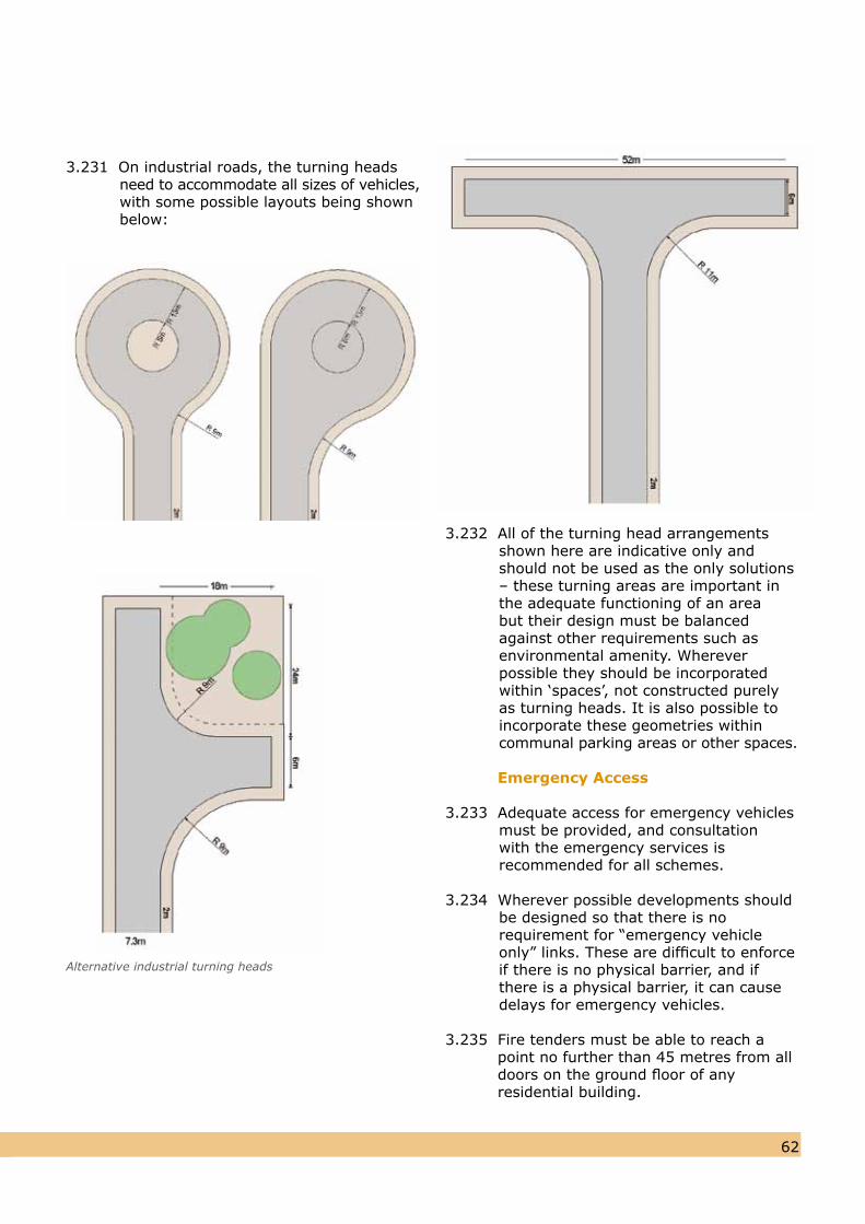
6261
3.231 On industrial roads, the turning heads need to accommodate all sizes of vehicles,with some possible layouts being shownbelow:
3.232 All of the turning head arrangements shown here are indicative only and should not be used as the only solutions– these turning areas are important in the adequate functioning of an areabut their design must be balanced against other requirements such asenvironmental amenity. Wherever possible they should be incorporated within ‘spaces’, not constructed purelyas turning heads. It is also possible toincorporate these geometries withincommunal parking areas or other spaces.
Emergency Access
3.233 Adequate access for emergency vehiclesmust be provided, and consultation with the emergency services is recommended for all schemes.
3.234 Wherever possible developments should be designed so that there is no requirement for “emergency vehicle only” links. These are difficult to enforceif there is no physical barrier, and if there is a physical barrier, it can cause delays for emergency vehicles.
3.235 Fire tenders must be able to reach a point no further than 45 metres from all doors on the ground floor of any residential building.
Alternative industrial turning heads
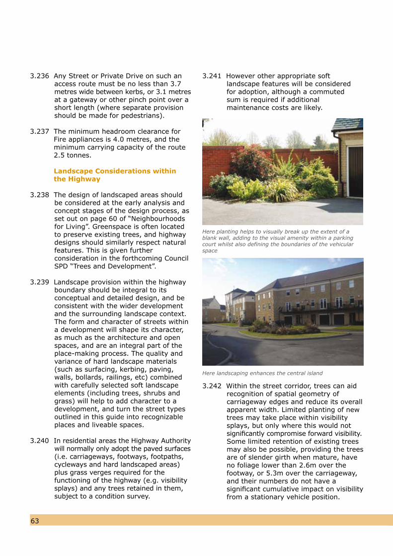
6463
3.236 Any Street or Private Drive on such anaccess route must be no less than 3.7metres wide between kerbs, or 3.1 metresat a gateway or other pinch point over a short length (where separate provision should be made for pedestrians).
3.237 The minimum headroom clearance for Fire appliances is 4.0 metres, and the minimum carrying capacity of the route 2.5 tonnes. Landscape Considerations within the Highway
3.238 The design of landscaped areas shouldbe considered at the early analysis and concept stages of the design process, as set out on page 60 of “Neighbourhoods for Living”. Greenspace is often locatedto preserve existing trees, and highway designs should similarly respect naturalfeatures. This is given further consideration in the forthcoming Council SPD “Trees and Development”.
3.239 Landscape provision within the highway boundary should be integral to its conceptual and detailed design, and be consistent with the wider development and the surrounding landscape context. The form and character of streets within a development will shape its character, as much as the architecture and open spaces, and are an integral part of the place-making process. The quality and variance of hard landscape materials (such as surfacing, kerbing, paving, walls, bollards, railings, etc) combined with carefully selected soft landscape elements (including trees, shrubs and grass) will help to add character to adevelopment, and turn the street types outlined in this guide into recognizable places and liveable spaces.
3.240 In residential areas the Highway Authoritywill normally only adopt the paved surfaces(i.e. carriageways, footways, footpaths, cycleways and hard landscaped areas) plus grass verges required for the functioning of the highway (e.g. visibility splays) and any trees retained in them,subject to a condition survey.
3.241 However other appropriate soft landscape features will be considered for adoption, although a commuted sum is required if additional maintenance costs are likely.
3.242 Within the street corridor, trees can aid recognition of spatial geometry of carriageway edges and reduce its overall apparent width. Limited planting of new trees may take place within visibility splays, but only where this would notsignificantly compromise forward visibility.Some limited retention of existing trees may also be possible, providing the trees are of slender girth when mature, have no foliage lower than 2.6m over the footway, or 5.3m over the carriageway, and their numbers do not have a significant cumulative impact on visibility from a stationary vehicle position.
Here planting helps to visually break up the extent of ablank wall, adding to the visual amenity within a parkingcourt whilst also defining the boundaries of the vehicularspace
Here landscaping enhances the central island
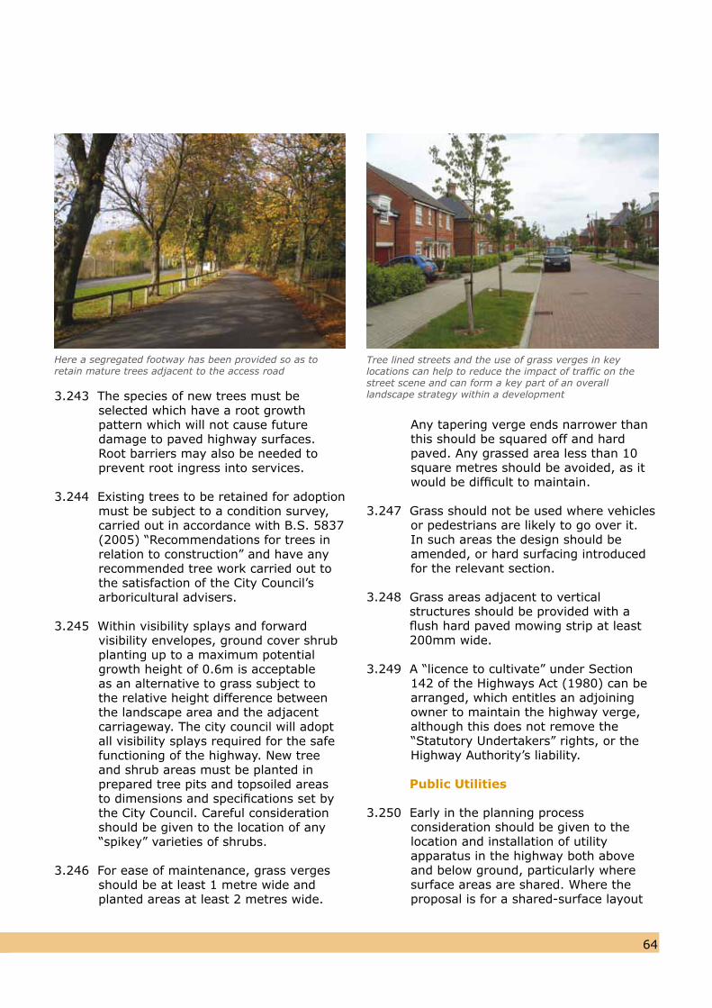
6463
3.243 The species of new trees must be selected which have a root growth pattern which will not cause future damage to paved highway surfaces. Root barriers may also be needed to prevent root ingress into services.
3.244 Existing trees to be retained for adoption must be subject to a condition survey, carried out in accordance with B.S. 5837(2005) “Recommendations for trees inrelation to construction” and have anyrecommended tree work carried out tothe satisfaction of the City Council’s arboricultural advisers.
3.245 Within visibility splays and forward visibility envelopes, ground cover shrub planting up to a maximum potential growth height of 0.6m is acceptable as an alternative to grass subject to the relative height difference between the landscape area and the adjacent carriageway. The city council will adopt all visibility splays required for the safe functioning of the highway. New tree and shrub areas must be planted in prepared tree pits and topsoiled areas to dimensions and specifications set by the City Council. Careful consideration should be given to the location of any“spikey” varieties of shrubs.
3.246 For ease of maintenance, grass verges
should be at least 1 metre wide and planted areas at least 2 metres wide.
Any tapering verge ends narrower than this should be squared off and hard paved. Any grassed area less than 10square metres should be avoided, as itwould be difficult to maintain.
3.247 Grass should not be used where vehicles or pedestrians are likely to go over it.In such areas the design should beamended, or hard surfacing introducedfor the relevant section.
3.248 Grass areas adjacent to vertical structures should be provided with a flush hard paved mowing strip at least 200mm wide.
3.249 A “licence to cultivate” under Section 142 of the Highways Act (1980) can be arranged, which entitles an adjoining owner to maintain the highway verge, although this does not remove the “Statutory Undertakers” rights, or theHighway Authority’s liability.
Public Utilities
3.250 Early in the planning process consideration should be given to the location and installation of utility apparatus in the highway both above and below ground, particularly where surface areas are shared. Where theproposal is for a shared-surface layout
Here a segregated footway has been provided so as toretain mature trees adjacent to the access road
Tree lined streets and the use of grass verges in key locations can help to reduce the impact of traffic on the street scene and can form a key part of an overalllandscape strategy within a development
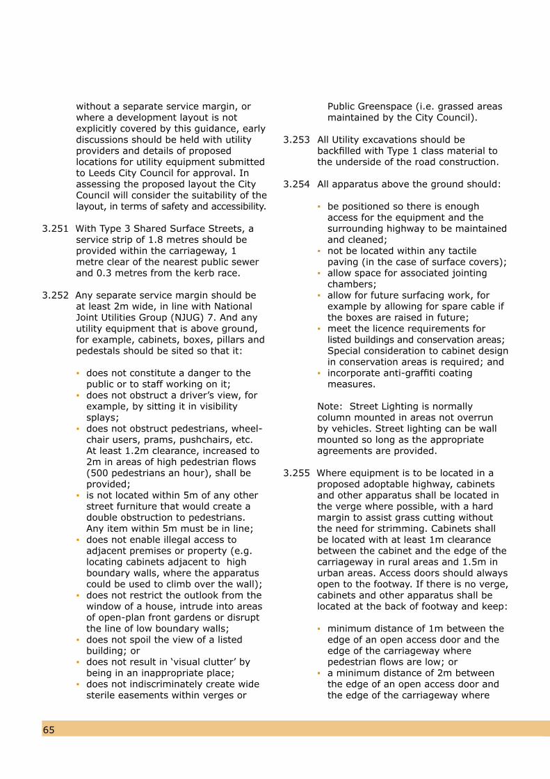
6665
without a separate service margin, orwhere a development layout is not explicitly covered by this guidance, earlydiscussions should be held with utility providers and details of proposed locations for utility equipment submittedto Leeds City Council for approval. Inassessing the proposed layout the CityCouncil will consider the suitability of thelayout, in terms of safety and accessibility.
3.251 With Type 3 Shared Surface Streets, a
service strip of 1.8 metres should be provided within the carriageway, 1 metre clear of the nearest public sewer and 0.3 metres from the kerb race.
3.252 Any separate service margin should beat least 2m wide, in line with National Joint Utilities Group (NJUG) 7. And any utility equipment that is above ground, for example, cabinets, boxes, pillars and pedestals should be sited so that it:
▪ does not constitute a danger to the public or to staff working on it; ▪ does not obstruct a driver’s view, for example, by sitting it in visibility splays; ▪ does not obstruct pedestrians, wheel- chair users, prams, pushchairs, etc. At least 1.2m clearance, increased to 2m in areas of high pedestrian flows (500 pedestrians an hour), shall be provided; ▪ is not located within 5m of any other street furniture that would create a double obstruction to pedestrians. Any item within 5m must be in line; ▪ does not enable illegal access to adjacent premises or property (e.g. locating cabinets adjacent to high boundary walls, where the apparatus could be used to climb over the wall); ▪ does not restrict the outlook from the window of a house, intrude into areas of open-plan front gardens or disrupt the line of low boundary walls; ▪ does not spoil the view of a listed building; or ▪ does not result in ‘visual clutter’ by being in an inappropriate place; ▪ does not indiscriminately create wide sterile easements within verges or
Public Greenspace (i.e. grassed areas maintained by the City Council).
3.253 All Utility excavations should be backfilled with Type 1 class material to the underside of the road construction.
3.254 All apparatus above the ground should:
▪ be positioned so there is enough access for the equipment and the surrounding highway to be maintained and cleaned; ▪ not be located within any tactile paving (in the case of surface covers); ▪ allow space for associated jointing chambers; ▪ allow for future surfacing work, for example by allowing for spare cable if the boxes are raised in future; ▪ meet the licence requirements for listed buildings and conservation areas; Special consideration to cabinet design in conservation areas is required; and ▪ incorporate anti-graffiti coating measures.
Note: Street Lighting is normally column mounted in areas not overrunby vehicles. Street lighting can be wall mounted so long as the appropriate agreements are provided.
3.255 Where equipment is to be located in aproposed adoptable highway, cabinets and other apparatus shall be located in the verge where possible, with a hard margin to assist grass cutting without the need for strimming. Cabinets shall be located with at least 1m clearance between the cabinet and the edge of the carriageway in rural areas and 1.5m in urban areas. Access doors should always open to the footway. If there is no verge, cabinets and other apparatus shall be located at the back of footway and keep:
▪ minimum distance of 1m between the edge of an open access door and the edge of the carriageway where pedestrian flows are low; or▪ a minimum distance of 2m between the edge of an open access door and the edge of the carriageway where
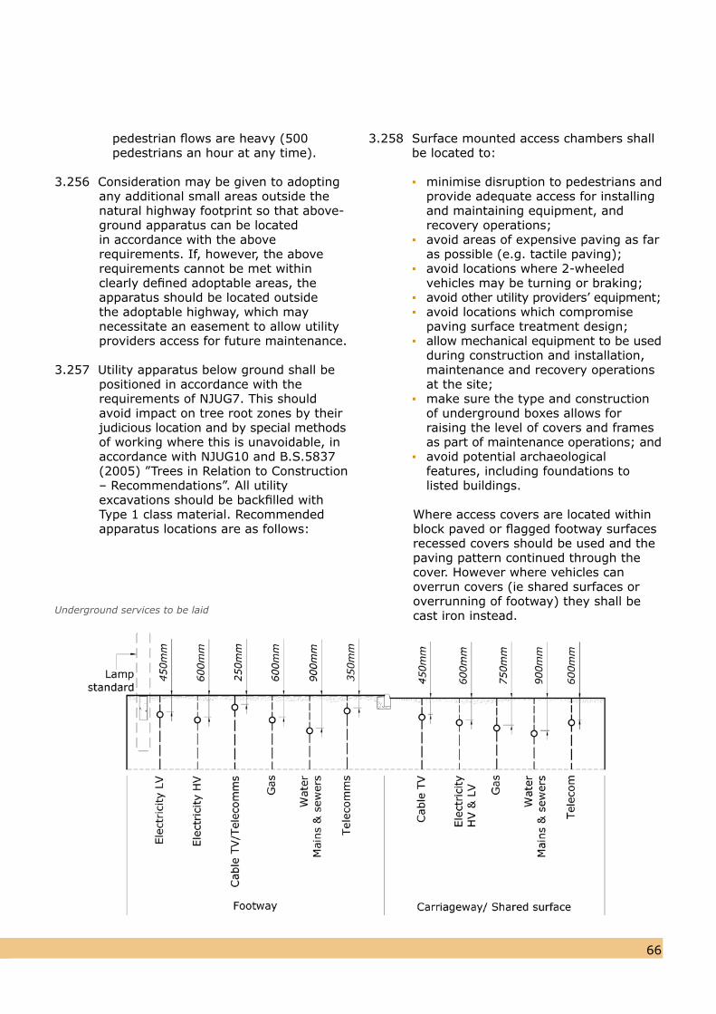
6665
pedestrian flows are heavy (500 pedestrians an hour at any time).
3.256 Consideration may be given to adopting any additional small areas outside thenatural highway footprint so that above-ground apparatus can be located in accordance with the above requirements. If, however, the above requirements cannot be met within clearly defined adoptable areas, the apparatus should be located outside the adoptable highway, which may necessitate an easement to allow utility providers access for future maintenance.
3.257 Utility apparatus below ground shall bepositioned in accordance with the requirements of NJUG7. This should avoid impact on tree root zones by theirjudicious location and by special methodsof working where this is unavoidable, in accordance with NJUG10 and B.S.5837 (2005) ”Trees in Relation to Construction – Recommendations”. All utility excavations should be backfilled with Type 1 class material. Recommended apparatus locations are as follows:
3.258 Surface mounted access chambers shall be located to:
▪ minimise disruption to pedestrians and provide adequate access for installing and maintaining equipment, and recovery operations; ▪ avoid areas of expensive paving as far as possible (e.g. tactile paving); ▪ avoid locations where 2-wheeled vehicles may be turning or braking; ▪ avoid other utility providers’ equipment; ▪ avoid locations which compromise paving surface treatment design; ▪ allow mechanical equipment to be used during construction and installation, maintenance and recovery operations at the site; ▪ make sure the type and construction of underground boxes allows for raising the level of covers and frames as part of maintenance operations; and ▪ avoid potential archaeological features, including foundations to listed buildings.
Where access covers are located withinblock paved or flagged footway surfacesrecessed covers should be used and thepaving pattern continued through thecover. However where vehicles can overrun covers (ie shared surfaces oroverrunning of footway) they shall becast iron instead.Underground services to be laid
6867
Drainage
3.259 All developments shall make adequate provision for draining surface water from the adoptable highway.
3.260 The use of alternative drainage systems including Sustainable Urban Drainage Systems flow attenuation and storage systems are encouraged, and will be considered on a site-by-site basis. Further information is set out in Appendix E of this Design Guide.
3.261 The term Sustainable Urban Drainage Systems (SUDS) covers the whole rangeof sustainable approaches to surface water drainage management. SUDS aim to mimic natural drainage processes and remove pollutants from urban run-off at source. SUDS comprise a wide range of techniques, including green roofs, permeable paving, rainwater harvesting, swales, detention basins, ponds, and wetlands. To realise thegreatest improvement in water qualityand flood risk management, these components should be used in combination, sometimes referred to asthe SUDS Management Train.
3.262 SUDS are more sustainable than conventional drainage methods because they:
▪ manage runoff flow rates, using infiltration and the retention of storm water; ▪ protect or enhance the water quality; ▪ are sympathetic to the environment setting and the needs of the local community; ▪ provide a habitat for wildlife in urban watercourses; and ▪ encourage nature groundwater recharge (where appropriate).
They do this by:
▪ dealing with runoff close to where the rain falls; ▪ managing potential pollution at its source; ▪ protecting water resources from
pollution created by accidental spills or other sources.
3.263 The use of SUDS is seen as a primary objective by the Government and should be applied wherever practical and technically feasible. It is proposed that all new streets that are large enough for SUDS to apply should submit a SUDS proposal. It is only when such a submission confirms that the scheme is not feasible will an alternative be considered.
3.264 Detailed guidance on SUDS is contained
in the “Interim Code of Practice forSustainable Urban Drainage Systems”, Part H of the Buildings Regulations andSewers for Adoption.
3.265 Only if SUDS are confirmed not to be feasible will highway run-off be intercepted and discharged directly to a public sewer adopted by the Water Authority. If this is not possible, run-off shall be discharged to a separate piped highway drainage system, which shall, with the approval of the appropriate drainage Authority, outfall either to a public sewer or a designated watercourse. Such a highway drainage system shall be adopted as part of the public highway under a Section 38 Agreement. Consent to outfall to a public sewer or watercourse should normally be obtained from Yorkshire Water or the Environment Agency respectively.
3.266 All highway drains shall be located within land to be adopted as highway. In exceptional circumstances it may bepermitted for a highway drain to cross private land outside the adopted highwayin accordance with Section 100 of the Highways Act (1980) in which case an easement agreement shall be required. The easement agreement shall be in place prior to or shall be a condition of the Highway Adoption Agreement (i.e. Section 38 or 278). Drainage easements should be located to avoid impact on retained trees and their root zones, and should not be located in Greenspace areas where they would
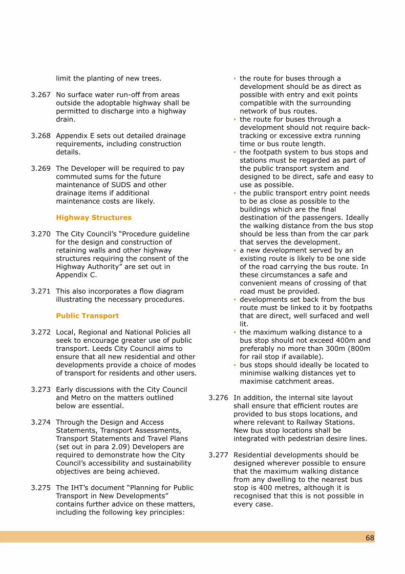
6867
limit the planting of new trees.
3.267 No surface water run-off from areas outside the adoptable highway shall be permitted to discharge into a highway drain.
3.268 Appendix E sets out detailed drainage requirements, including construction details.
3.269 The Developer will be required to pay commuted sums for the future maintenance of SUDS and other drainage items if additional maintenance costs are likely.
Highway Structures
3.270 The City Council’s “Procedure guidelinefor the design and construction ofretaining walls and other highway structures requiring the consent of theHighway Authority” are set out inAppendix C.
3.271 This also incorporates a flow diagram illustrating the necessary procedures. Public Transport
3.272 Local, Regional and National Policies allseek to encourage greater use of publictransport. Leeds City Council aims toensure that all new residential and otherdevelopments provide a choice of modesof transport for residents and other users.
3.273 Early discussions with the City Counciland Metro on the matters outlinedbelow are essential.
3.274 Through the Design and Access Statements, Transport Assessments, Transport Statements and Travel Plans (set out in para 2.09) Developers are required to demonstrate how the City Council’s accessibility and sustainability objectives are being achieved.
3.275 The IHT’s document “Planning for PublicTransport in New Developments” contains further advice on these matters,including the following key principles:
▪ the route for buses through a development should be as direct as possible with entry and exit points compatible with the surrounding network of bus routes. ▪ the route for buses through a development should not require back- tracking or excessive extra running time or bus route length. ▪ the footpath system to bus stops and stations must be regarded as part of the public transport system and designed to be direct, safe and easy to use as possible. ▪ the public transport entry point needs to be as close as possible to the buildings which are the final destination of the passengers. Ideally the walking distance from the bus stop should be less than from the car park that serves the development. ▪ a new development served by an existing route is likely to be one side of the road carrying the bus route. In these circumstances a safe and convenient means of crossing of that road must be provided. ▪ developments set back from the bus route must be linked to it by footpaths that are direct, well surfaced and well lit. ▪ the maximum walking distance to a bus stop should not exceed 400m and preferably no more than 300m (800m for rail stop if available). ▪ bus stops should ideally be located to minimise walking distances yet to maximise catchment areas.
3.276 In addition, the internal site layout shall ensure that efficient routes are provided to bus stops locations, and where relevant to Railway Stations.New bus stop locations shall be integrated with pedestrian desire lines.
3.277 Residential developments should bedesigned wherever possible to ensurethat the maximum walking distancefrom any dwelling to the nearest busstop is 400 metres, although it isrecognised that this is not possible inevery case.
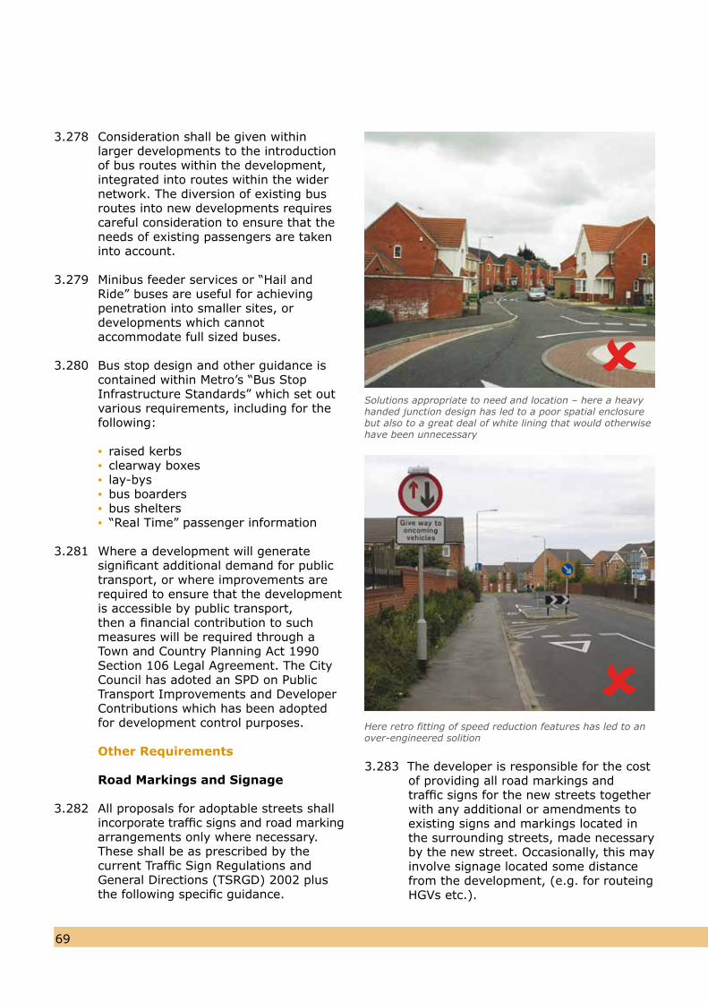
3.278 Consideration shall be given within larger developments to the introduction of bus routes within the development, integrated into routes within the wider network. The diversion of existing busroutes into new developments requirescareful consideration to ensure that theneeds of existing passengers are takeninto account.
3.279 Minibus feeder services or “Hail and Ride” buses are useful for achieving penetration into smaller sites, ordevelopments which cannot accommodate full sized buses.
3.280 Bus stop design and other guidance is contained within Metro’s “Bus Stop Infrastructure Standards” which set out various requirements, including for the following:
▪ raised kerbs ▪ clearway boxes ▪ lay-bys ▪ bus boarders ▪ bus shelters ▪ “Real Time” passenger information
3.281 Where a development will generate significant additional demand for public transport, or where improvements are required to ensure that the development is accessible by public transport, then a financial contribution to such measures will be required through a Town and Country Planning Act 1990 Section 106 Legal Agreement. The City Council has adoted an SPD on Public Transport Improvements and Developer Contributions which has been adopted for development control purposes.
Other Requirements
Road Markings and Signage
3.282 All proposals for adoptable streets shall incorporate traffic signs and road markingarrangements only where necessary. These shall be as prescribed by the current Traffic Sign Regulations and General Directions (TSRGD) 2002 plusthe following specific guidance.
7069
3.283 The developer is responsible for the costof providing all road markings and traffic signs for the new streets together with any additional or amendments to existing signs and markings located in the surrounding streets, made necessary by the new street. Occasionally, this mayinvolve signage located some distancefrom the development, (e.g. for routeingHGVs etc.).
Solutions appropriate to need and location – here a heavyhanded junction design has led to a poor spatial enclosurebut also to a great deal of white lining that would otherwisehave been unnecessary
Here retro fitting of speed reduction features has led to anover-engineered solition
7069
3.284 Where required, at the site access to developments, road markings and signs
should be provided in accordance withTSRGD.
3.285 All Type 2, 3b and 4 streets should besigned as 20mph zones at their entrance from the wider 30mph network. This will require an appropriate Speed Limit Order, and the design should ensure that the zone limit is self enforcing. Type 3a streets will also need to be signed as a 20mph zone, except wherethey form part of a through route whichis not signed at 20mph.
3.286 The design and location of signage andstreet furniture should aim to minimisevisual clutter.
3.287 Street name plates will be provided bythe City Council, with the cost to be notified to the Developer as a separate item to the other road signs.
3.288 Developers wishing to erect signs directing construction traffic or potential purchasers to a site must contact the City Council for permission to erect approved signs. Signs which have not been approved will be removed.
Traffic Regulation Orders (TROs)
3.289 Where a development requires changes to an existing Traffic Regulation Order (TRO) or a new order is required, the Developer shall pay all associated costs, including all staff, consultation and legal costs. TROs are subject to statutory procedures and consultations. This can be a very lengthy process and a successful outcome is not guaranteed. The Developer must therefore obtain advice on the likely timescale and take this into consideration when establishing a programme for development.
3.290 Where TROs are critical to the Development, they should be completed and sealed prior to the first occupation.
Adoption Procedures
3.291 Leeds City Council’s adoption policies, requirements and procedures are set out in Appendix B.
3.292 A commuted sum is required for alladoptions and shall generally be in accordance with guidance issued by theDfT. Enhanced commuted sums arerequired for any elements whereabnormal maintenance costs are likelyto occur.
Street Lighting
3.293 Leeds City Council’s procedures for theadoption (accrual) of Street Lightingand Illuminative Apparatus are set out inAppendix D.
3.294 In certain rural or other situations it maybe necessary to provide alternative Street Lighting details (e.g. sensitive column designs in Conservation Areas,lights on buildings rather than columnsin unlit villages, etc). These situationsshould be discussed further with theLocal Authority.
Crime and Disorder
3.295 Local Authorities are obliged under Crime and Disorder Act 1998 to consider the crime and disorder implications of all planning applications. Crime prevention through environmental design (CPTED) is a concept that focuses on designing out crime by developing an understanding of the factors that are likely to contribute to a higher incidence of crime within a community. The built environment can have both a positive and negative impact upon criminal activities, and is a crucial factor to how safe and secure people feel within their community. However, planning out crime can only work if it is part of a wider strategy incorporating other measures such as regeneration, community involvement and town centre management.
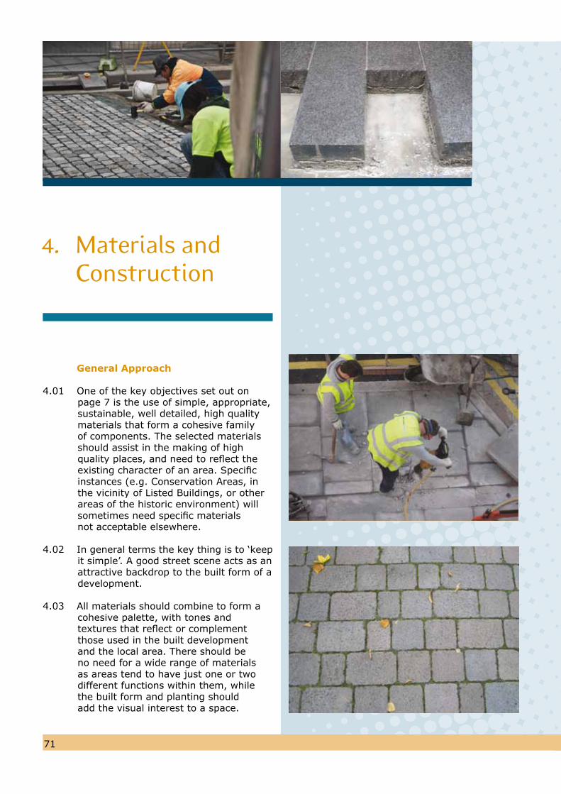
General Approach
4.01 One of the key objectives set out on page 7 is the use of simple, appropriate, sustainable, well detailed, high quality materials that form a cohesive family of components. The selected materials should assist in the making of high quality places, and need to reflect the existing character of an area. Specific instances (e.g. Conservation Areas, in the vicinity of Listed Buildings, or other areas of the historic environment) will sometimes need specific materials not acceptable elsewhere.
4.02 In general terms the key thing is to ‘keepit simple’. A good street scene acts as anattractive backdrop to the built form of adevelopment.
4.03 All materials should combine to form a
cohesive palette, with tones and textures that reflect or complement those used in the built development and the local area. There should be no need for a wide range of materials as areas tend to have just one or two different functions within them, while the built form and planting should add the visual interest to a space.
4. Materials and Construction
7271
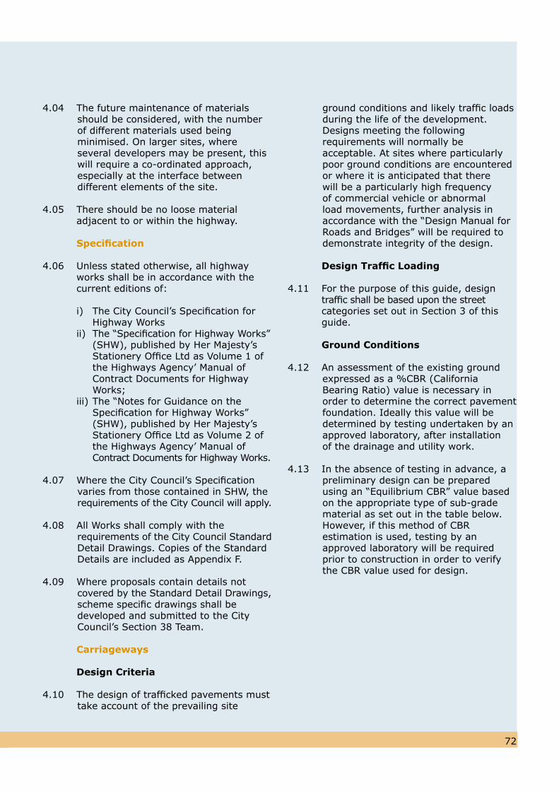
4.04 The future maintenance of materials should be considered, with the number of different materials used being minimised. On larger sites, where several developers may be present, this will require a co-ordinated approach, especially at the interface between different elements of the site.
4.05 There should be no loose material adjacent to or within the highway.
Specification
4.06 Unless stated otherwise, all highway works shall be in accordance with the current editions of:
i) The City Council’s Specification for Highway Works ii) The “Specification for Highway Works” (SHW), published by Her Majesty’s Stationery Office Ltd as Volume 1 of the Highways Agency’ Manual of Contract Documents for Highway Works; iii) The “Notes for Guidance on the Specification for Highway Works” (SHW), published by Her Majesty’s Stationery Office Ltd as Volume 2 of the Highways Agency’ Manual of Contract Documents for Highway Works.
4.07 Where the City Council’s Specification varies from those contained in SHW, therequirements of the City Council will apply.
4.08 All Works shall comply with the requirements of the City Council StandardDetail Drawings. Copies of the Standard Details are included as Appendix F.
4.09 Where proposals contain details notcovered by the Standard Detail Drawings,scheme specific drawings shall be developed and submitted to the CityCouncil’s Section 38 Team.
Carriageways
Design Criteria
4.10 The design of trafficked pavements musttake account of the prevailing site
ground conditions and likely traffic loadsduring the life of the development. Designs meeting the following requirements will normally be acceptable. At sites where particularly poor ground conditions are encountered or where it is anticipated that there will be a particularly high frequency of commercial vehicle or abnormal load movements, further analysis in accordance with the “Design Manual for Roads and Bridges” will be required to demonstrate integrity of the design.
Design Traffic Loading
4.11 For the purpose of this guide, design traffic shall be based upon the street categories set out in Section 3 of this guide.
Ground Conditions
4.12 An assessment of the existing ground expressed as a %CBR (California Bearing Ratio) value is necessary in order to determine the correct pavement foundation. Ideally this value will be determined by testing undertaken by an approved laboratory, after installation of the drainage and utility work.
4.13 In the absence of testing in advance, apreliminary design can be prepared using an “Equilibrium CBR” value basedon the appropriate type of sub-gradematerial as set out in the table below.However, if this method of CBR estimation is used, testing by an approved laboratory will be required prior to construction in order to verify the CBR value used for design.
7271
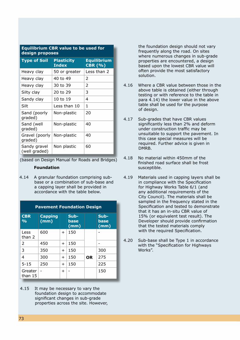
Foundation
4.14 A granular foundation comprising sub-base or a combination of sub-base anda capping layer shall be provided in accordance with the table below.
4.15 It may be necessary to vary the foundation design to accommodate significant changes in sub-grade properties across the site. However,
the foundation design should not vary frequently along the road. On sites where numerous changes in sub-gradeproperties are encountered, a designbased upon the lowest CBR value willoften provide the most satisfactorysolution.
4.16 Where a CBR value between those in theabove table is obtained (either throughtesting or with reference to the table inpara 4.14) the lower value in the abovetable shall be used for the purposeof design.
4.17 Sub-grades that have CBR values significantly less than 2% and deform under construction traffic may beunsuitable to support the pavement. Inthis case special measures will berequired. Further advice is given inDMRB.
4.18 No material within 450mm of the finished road surface shall be frost susceptible.
4.19 Materials used in capping layers shall bein compliance with the Specification for Highway Works Table 6/1 (and any additional requirements of the City Council). The materials shall be sampled in the frequency stated in the Specification and tested to demonstrate that it has an in-situ CBR value of15% (or equivalent test result). The Developer should provide confirmation that the tested materials comply with the required Specification.
4.20 Sub-base shall be Type 1 in accordance with the “Specification for Highways Works”.
7473
Equilibrium CBR value to be used fordesign proposes
Type of Soil Plasticity Index
Equilibrium CBR (%)
Heavy clay 50 or greater Less than 2
Heavy clay 40 to 49 2
Heavy clay 30 to 39 2
Silty clay 20 to 29 3
Sandy clay 10 to 19 4
Silt Less than 10 1
Sand (poorly graded)
Non-plastic 20
Sand (well graded)
Non-plastic 40
Gravel (poorly graded)
Non-plastic 40
Sandy gravel (well graded)
Non plastic 60
(based on Design Manual for Roads and Bridges)
Pavement Foundation Design
CBR %
Capping (mm)
Sub-base(mm)
Sub-base (mm)
Less than 2
600 + 150 -
2 450 + 150 -
3 350 + 150
OR
300
4 300 + 150 275
5-15 250 + 150 225
Greater than 15
- + - 150
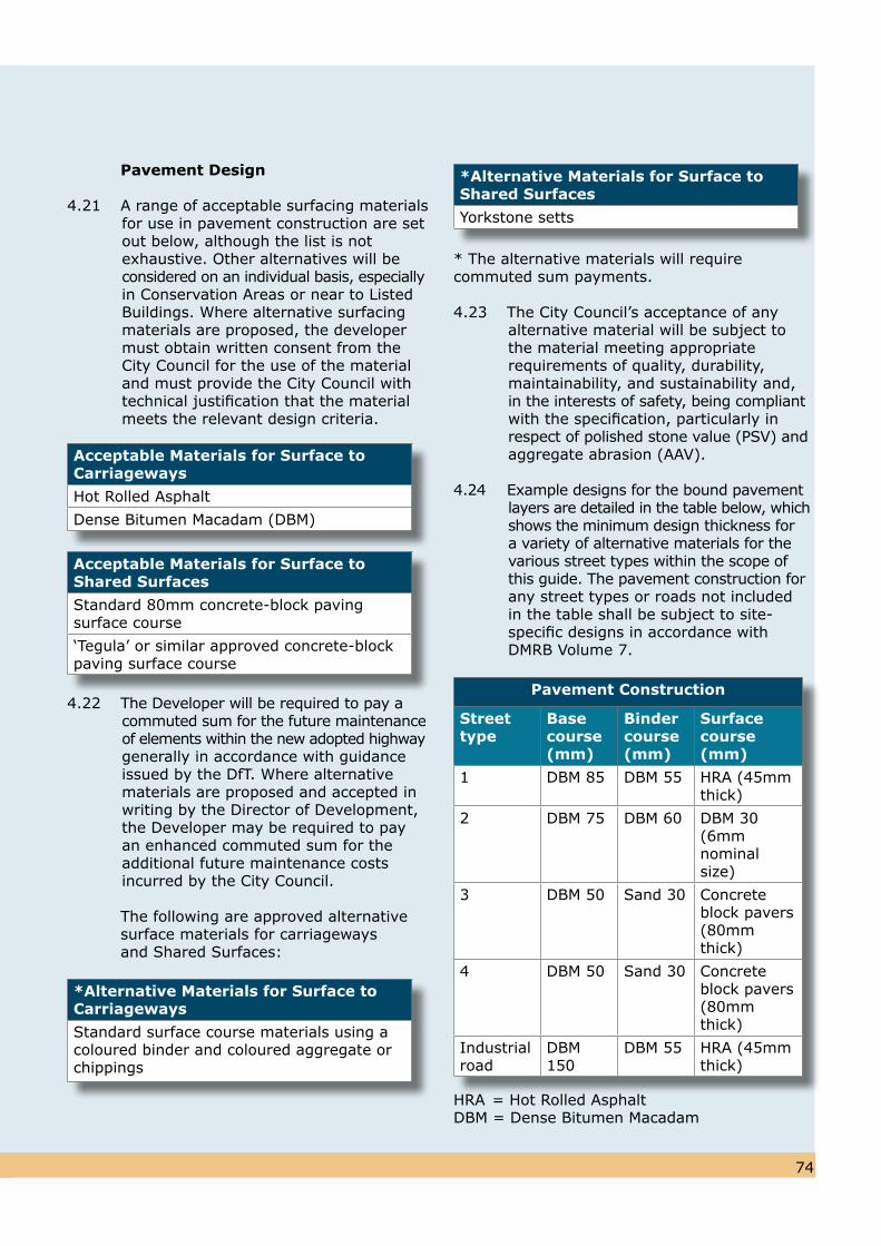
Pavement Design
4.21 A range of acceptable surfacing materials for use in pavement construction are setout below, although the list is not exhaustive. Other alternatives will beconsidered on an individual basis, especiallyin Conservation Areas or near to Listed Buildings. Where alternative surfacing materials are proposed, the developer must obtain written consent from the City Council for the use of the material and must provide the City Council with technical justification that the material meets the relevant design criteria.
4.22 The Developer will be required to pay acommuted sum for the future maintenance of elements within the new adopted highway generally in accordance with guidance issued by the DfT. Where alternative materials are proposed and accepted in writing by the Director of Development, the Developer may be required to pay an enhanced commuted sum for theadditional future maintenance costs incurred by the City Council.
The following are approved alternative surface materials for carriageways and Shared Surfaces:
7473
* The alternative materials will require commuted sum payments.
4.23 The City Council’s acceptance of any alternative material will be subject tothe material meeting appropriate requirements of quality, durability, maintainability, and sustainability and,in the interests of safety, being compliantwith the specification, particularly inrespect of polished stone value (PSV) andaggregate abrasion (AAV).
4.24 Example designs for the bound pavementlayers are detailed in the table below, whichshows the minimum design thickness fora variety of alternative materials for the various street types within the scope of this guide. The pavement construction forany street types or roads not includedin the table shall be subject to site-specific designs in accordance withDMRB Volume 7.
HRA = Hot Rolled AsphaltDBM = Dense Bitumen Macadam
Acceptable Materials for Surface toCarriageways
Hot Rolled Asphalt
Dense Bitumen Macadam (DBM)
Acceptable Materials for Surface toShared Surfaces
Standard 80mm concrete-block pavingsurface course
‘Tegula’ or similar approved concrete-blockpaving surface course
*Alternative Materials for Surface toCarriageways
Standard surface course materials using acoloured binder and coloured aggregate orchippings
*Alternative Materials for Surface toShared Surfaces
Yorkstone setts
Pavement Construction
Street type
Base course (mm)
Binder course (mm)
Surfacecourse(mm)
1 DBM 85 DBM 55 HRA (45mm thick)
2 DBM 75 DBM 60 DBM 30 (6mm nominal size)
3 DBM 50 Sand 30 Concrete block pavers (80mm thick)
4 DBM 50 Sand 30 Concrete block pavers (80mm thick)
Industrial road
DBM 150
DBM 55 HRA (45mm thick)
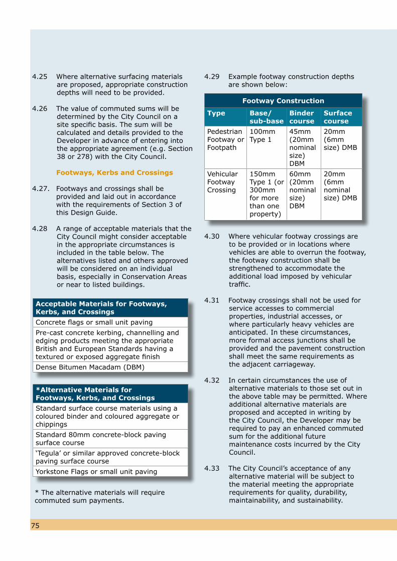
7675
4.25 Where alternative surfacing materials are proposed, appropriate construction depths will need to be provided.
4.26 The value of commuted sums will bedetermined by the City Council on a site specific basis. The sum will be calculated and details provided to theDeveloper in advance of entering into the appropriate agreement (e.g. Section 38 or 278) with the City Council.
Footways, Kerbs and Crossings
4.27. Footways and crossings shall be provided and laid out in accordance with the requirements of Section 3 of this Design Guide.
4.28 A range of acceptable materials that theCity Council might consider acceptable in the appropriate circumstances isincluded in the table below. The alternatives listed and others approved will be considered on an individual basis, especially in Conservation Areasor near to listed buildings.
4.29 Example footway construction depths are shown below:
4.30 Where vehicular footway crossings areto be provided or in locations wherevehicles are able to overrun the footway,the footway construction shall be strengthened to accommodate theadditional load imposed by vehiculartraffic.
4.31 Footway crossings shall not be used forservice accesses to commercial properties, industrial accesses, or where particularly heavy vehicles are anticipated. In these circumstances, more formal access junctions shall be provided and the pavement construction shall meet the same requirements asthe adjacent carriageway.
4.32 In certain circumstances the use ofalternative materials to those set out inthe above table may be permitted. Whereadditional alternative materials areproposed and accepted in writing bythe City Council, the Developer may berequired to pay an enhanced commutedsum for the additional futuremaintenance costs incurred by the CityCouncil.
4.33 The City Council’s acceptance of anyalternative material will be subject to the material meeting the appropriate requirements for quality, durability, maintainability, and sustainability.
* The alternative materials will require commuted sum payments.
Acceptable Materials for Footways, Kerbs, and Crossings
Concrete flags or small unit paving
Pre-cast concrete kerbing, channelling and edging products meeting the appropriate British and European Standards having atextured or exposed aggregate finish
Dense Bitumen Macadam (DBM)
*Alternative Materials for Footways, Kerbs, and Crossings
Standard surface course materials using acoloured binder and coloured aggregate orchippings
Standard 80mm concrete-block pavingsurface course
‘Tegula’ or similar approved concrete-blockpaving surface course
Yorkstone Flags or small unit paving
Footway Construction
Type Base/sub-base
Binder course
Surfacecourse
Pedestrian Footway or Footpath
100mm Type 1
45mm (20mm nominal size) DBM
20mm (6mm size) DMB
Vehicular Footway Crossing
150mm Type 1 (or 300mm for more than one property)
60mm (20mm nominal size) DBM
20mm (6mm nominal size) DMB
7675
4.34 Kerbs shall normally be provided alongside all running carriageways (Types 1 and 2) to provide an edgerestraint to the carriageway construction,prevent vehicles overriding the footway,and facilitate the management ofdrainage flows.
4.35 Where kerbs are laid alongside the running carriageway they shall be laid with an up-stand of 100mm (except in shared surface streets). At bus stops this should be increased to 180mm, andMetro should be consulted for anyadditional requirements.
4.36 Drop Kerbs shall be used at pedestrian and vehicular crossing points. They shouldbe constructed flush with the carriagewayat pedestrian crossing points and witha 25mm check at vehicular crossings, and shall be constructed in accordance with the Standard Detail Drawings.
4.37 Pre-cast concrete channel blocks shall be installed in the road channel adjacent to the kerb wherever the longitudinal gradient along the road channel is between 1 in 150 and 1 in 120. The channels shall be laid in accordance withthe Standard Detail Drawings.
4.38 Tactile paving to assist blind and partially sighted people should be utilised in accordance with national guidance.
4.39 The value of commuted sums will bedetermined by the City Council on a site specific basis. The sum will be calculated and details provided to theDeveloper in advance of entering into the appropriate agreement (e.g. Section 38 or 278) with the City Council.
Drainage
4.40 For details of drainage construction requirements see Appendix E.
Conservation Areas
4.41 Traditional paving materials, where theystill exist, contribute to the character of a conservation area. Therefore in
carrying out maintenance, or the provision of new streets, within these areas it is necessary that traditional materials are used. These materials are likely to be made of stone, although alternative new materials such as tegula blocks, conservation kerbs and tarmac dressed with a suitable local aggregate may also be acceptable.
4.42 Street furniture should also be ofappropriate materials in keeping with the surrounding area. Advice from the City Council should be sought prior to designing or implementing any works.
Index
A
Access Emergency services 62 - 63 Service vehicles 59 - 62 Pedestrian 56, 58Adoption 70 Appendix BAlternative Materials 74, 75Audits (Quality and Road Safety) 6
B
Bends Carriageway widths 12, 17, 21, 29, 60 Speed control 33 Visibility 26Blind & Partially sighted People 49 Provision for 5, 18, 22 Tactile paving 18, 24, 49, 76 Buses Carriageway widths 12,17, 21 Footway widths 12, 44 Routes 32, 34 Stops 43, 44
C Carriageway Design Criteria 72 Design Traffic loading 72 Foundation 73 Gradients 35 Ground Conditions 72 Materials 71 - 76 Narrowing 33 Passing places 27, 28, 60 Pavement Design 74 Widths 12, 17, 21, 27 - 28, 29, 60Car Clubs 53, 59Car Parking 50 – 59 Car free developments 59 Commercial and Industrial developments 30, 59 Communal areas 30, 57 – 58, 62 Disabled Car Parking 49 - 50 Driveway 56 Garages 56 - 57
Number of spaces 52 - 55 Allocated 52 - 55 Unallocated 54 - 55 On-street Provision 12, 17, 21, 23, 39, 58, 60 Principles 50 - 51 Visibility 57 Visitor Parking 28Centreline Radii 12, 17, 21, 23, 29, 33Commuted Sums 68, 70, 75, 76Connectivity 9, 13, 44, 46Connector Streets (Type 1) 12 - 14Conservation Areas 65, 70, 71, 74, 75, 76Crime & Disorder 70 Crossing Points 45Crossroads 42Culs-de-sac 9, 17, 21, 23Cycling 45 - 48 Access control 46 Parking 47 Principles 45 Visibility 47 Widths 46
D
Design and Access Statements 5, 32, 68Design Manual for Roads and Bridges 8, 27, 29, 31, 72Design Principles 4Design Speeds 11, 12, 17, 21, 23, 25, 29Designated Routes 11, 18, 21, 43Designing for Disabled People 49 – 50 Parking 49 Principles 49 Ramps 49 Tactile paving 49Direct Vehicular Access 12, 17, 21, 23Distributor Roads and Strategic Routes 36, Appendix GDrainage 67 – 68 Appendix E Drives 28, 56 Design 35Dropped Kerbs 45, 50
E
Easements 65, 67Emergency Access 62 – 63 Emergency Vehicles 3, 35, 62
F
Flood Levels 8, 36Footpaths Cyclists 46
7877
Design 43, 44, 45Footways Construction 75 Cyclists 44 Layout 13, 41 Width 12, 17, 23, 29, 34, 44Forward Visibility 26, 33, 35, 60, 63, 64
G
Garages 35, 47, 56 – 57Gates 28, 30Gateways 33Gradients Carriageway 34, 35, 43 Footways 44 Ramps 49Ground Conditions 72
H
Hierarchies 3, 8 – 10Highway Structures 68 Appendix CHome Zones (type 4) 8, 11, 24 – 25, 32, 57
I
Industrial Developments 28 – 30, 48
J
Junction Layouts and Visibility 36 - 43 Junction Layouts 40 Junction Spacing 42 Measurement of Splays 36 Obstacles to Visibility 38 Principles 36 X-Distance 38 Y-Distance 39K
Kerbing 75 - 76Key Objectives 7
L
Landscaping 32, 57, 63 - 64 Maintenance 64 Trees 33, 34Level Surface Streets (Type 3b) 22 - 23Lighting 65Local Residential Streets (Type 2) 15 - 17
M
Maintenance 6, 10, 36, 39Manual for Streets 1, 10, 36, 39Materials 71 - 74Mixed Use Schemes 8, 29, 31Multidisciplinary Approach 4
N
Neighbourhoods for Living 1, 3, 4, 5, 9, 51, 63Number of Access Points 12, 17, 21, 23
P
Parking see car parkingPassing bays 27Pavement Design 72Pavement materials 71 – 76Pedestrian Movement 43 – 45 Crossing Points 45 Principles 43 Steps 44 Vertical clearance 44 Widths 44Pedestrians Designated Routes 18, 21, 24, 43 Desire Lines 34, 35, 43 Provision 11 Refuges 45 Shared Surface 11, 22 Sightlines 57Private Drives and Streets 28, 41, 63Public Transport 35, 59, 68 - 69Public Utilities 64 - 66
Q
Quality Audits 6
R
Radii at Junctions 40 – 41, 45 Ramps 34, 49Refuse Vehicles 28, 33, 60 - 62Road Markings 69 – 70 Road Safety Audits 6
S
Servicing 59 – 62 Principles 59 Requirements 60Turning heads 60, 61, 62Scope of Design Guide 8
7877
79
Shared Space Streets (Type 3a) 18 – 21 Signage 32, 69 – 70 Spacing of Junctions 42Specification 72Speed Restraints 31 – 35 Carriageway Narrowing 33 Control Bends 33 Gateways 33 Ramps 34 Tables 34Speed Limits 11, 42, 70Standard Construction details Appendix FSteps 44Street Hierarchy 3, 8 – 11 Street Furniture 44, 49, 70, 76Street Lighting 65, 70 Appendix DStreet Types 8 – 31 Carriageway widths 27 General Approach 8 Industrial Developments 28 Measurement of Forward Visibility 26 Mixed Use Schemes 31 Private Streets & Drives 28 Street Hierarchy 8 Street Type 1 (Connector Streets) 12 – 14 Street Type 2 (Local Residential Streets) 15 – 17 Street Type 3a (Shared Space Streets) 18 – 21 Street Type 3b (Level Surface Streets) 22 – 23 Street Type 4 (Home Zones) 24 – 25 Stopping Distances 26Structures 68 Appendix CSUDS 67Sustainability 2, 5, 68, 74, 75
T
Tactile Paving 18, 24, 46, 49, 76Traffic Regulation Orders 59, 70Transportation Assessments / Statements 5, 68Travel Plans 6, 59, 68Trees 7, 34, 39, 63 – 64 Turning Heads 54, 59, 60 – 62
U
Underground Services 64 - 66Urban Design Principles 1, 4, 5, Appendix AUser Hierarchy 3
V
Vehicle Speeds 7, 27, 33, 34, 36, 39Verges 12, 13, 44, 63, 64, 65Visibility 26, 35, 36 – 39, 42, 43, 47, 60, 63, 64Vertical Alignment 35 – 36 Vertical Clearance 35, 44Visitor Parking 51, 52, 53, 54Visibility Splays 37, 39, 63, 64Visibility Zone 42
W
Wheelchair users 9, 39, 44, 49, 65

79
Supplementary Planning DocumentAugust 2009
Contact Details
Write to: Local Develpment Framework Administration and Information Officer Leeds City Council Thoresby House, Level 3 2 Rossington Street LEEDS LS2 8HD
Telephone: 0113 247 78075
Email: [email protected]
Web: www.leeds.gov.uk/ldf
Street Design Guide Leeds Local Development Framework
Prin
ted o
n p
aper
mad
e fr
om
80%
post
consu
mer
was
te a
nd 2
0%
rec
ycle
d indust
rial
fibre
s