lee & mudawar 2008 fluid flow and heat transfer characteristics of low temperature two phase...
DESCRIPTION
Fluid Flow and Heat Transfer Characteristics of Low Temperature Two Phase Microchannel Heat Sink - P2TRANSCRIPT

Available online at www.sciencedirect.com
www.elsevier.com/locate/ijhmt
International Journal of Heat and Mass Transfer 51 (2008) 4327–4341
Fluid flow and heat transfer characteristics of low temperaturetwo-phase micro-channel heat sinks – Part 2. Subcooled boiling
pressure drop and heat transfer
Jaeseon Lee, Issam Mudawar *
Boiling and Two-Phase Flow Laboratory (BTPFL), Purdue University International Electronic Cooling Alliance (PUIECA),
Mechanical Engineering Building, 585 Purdue Mall, West Lafayette, IN 47907-2088, USA
Received 13 June 2007; received in revised form 16 February 2008Available online 22 May 2008
Abstract
This second part of a two-part study explores the performance of a new cooling scheme in which the primary working fluid flowingthrough a micro-channel heat sink is indirectly cooled by a refrigeration cooling system. The objective of this part of study is to explorethe pressure drop and heat transfer characteristics of the heat sink. During single-phase cooling, pressure drop decreased with increasingheat flux because of decreased liquid viscosity. However, pressure drop began increasing with increasing heat flux following bubble depar-ture. These opposite trends produced a minimum in the variation of pressure drop with heat flux. Increasing liquid subcooling decreasedtwo-phase pressure drop because of decreased void fraction caused by strong condensation at bubble interfaces as well as decreased like-lihood of bubble coalescence. It is shown macro-channel subcooled boiling pressure drop and heat transfer correlations are unsuitable formicro-channel flows. However, two new modified correlations produced good predictions of the present heat transfer data.� 2008 Elsevier Ltd. All rights reserved.
1. Introduction
1.1. Application of subcooled flow boiling for high-flux
cooling
Flow boiling is known for its ability to produce veryhigh convective heat transfer coefficients, which is why itis widely used in many applications demanding high-fluxheat removal. Two main regimes are possible with flowboiling, subcooled and saturated; each is also made up ofsub-regimes. Subcooled and saturated boiling can occurconcurrently in a long heated channel if the incoming fluidis supplied below saturation temperature corresponding tothe inlet pressure. With an inlet thermodynamic equilib-rium quality below zero, subcooled boiling prevails in theinlet region and, as the quality rises along the channel, apoint is reached where transition to saturated boiling takes
0017-9310/$ - see front matter � 2008 Elsevier Ltd. All rights reserved.
doi:10.1016/j.ijheatmasstransfer.2008.02.013
* Corresponding author. Tel.: +1 (765) 494 5705; fax: +1 (765) 494 0539.E-mail address: [email protected] (I. Mudawar).
effect. Because of large differences in void fraction, the heattransfer mechanism for subcooled boiling is categoricallydifferent from that for saturated boiling. In the subcooledregion, liquid flow is more abundant and phase-changeoccurs mostly by bubble formation at the wall. High voidfractions in saturated boiling are associated with churn,slug and annular flows in which bubble nucleation is grad-ually replaced by evaporation of a residual liquid film atthe heated wall.
In general, higher average heat transfer coefficients arepossible with subcooled flow boiling than with saturated.Critical heat flux (CHF) is also greater for subcooled boil-ing. Furthermore, there are drastic differences in CHFmechanism between the two regimes. Subcooled CHF(commonly referred to as ‘‘departure from nucleate boiling”or DNB for short) is the result of localized vapor blanketformation along the heated wall even while liquid is abun-dant in the core. On the other hand, CHF in saturated boil-ing occurs in a predominantly liquid deficient region and isusually the result of dryout of the annular liquid film.

Nomenclature
Abase total base area of micro-channel heat sinkBo Boiling numberCHF critical heat fluxcp specific heatDh hydraulic diameter of micro-channelf friction factorFf constant in Eqs. (10) and (11)G mass velocityh heat transfer coefficient; enthalpy�h mean heat transfer coefficient across base of
heat sinkHch height of micro-channelhfg latent heat of vaporization
Ja* modified Jacob numberL length of micro-channel_m total mass flow rate of coolant entering heat
sinkN constant in Eq. (5)Nu Nusselt numberONB onset of nucleate boilingP pressureDP pressure dropPr Prandtl numberq00 heat flux through heat sink base areaReDh Reynolds number based on hydraulic diameter
of micro-channelT temperatureTS test sectionTw base wall temperature of micro-channel heat
sinkT w mean base wall temperature of micro-channel
heat sinkv specific volumeWch width of micro-channel
Ww half-width of solid wall separating micro-chan-nels
We* modified Weber numberxe thermodynamic equilibrium qualityz streamwise coordinate
Greek symbols
b channel aspect ratio/ fluid phase indicationl viscosityq densityr surface tension
Subscripts
– phase averaged property1,2,3 measurement locationsA accelerational pressure drop componentad adiabaticbd bubble departure from wallch micro-channele thermodynamic equilibriumexp experimental (measured)F frictional pressure drop componentf liquidg saturated vaporin micro-channel inletONB onset of nucleate boilingout micro-channel outletpred predictedsat saturatedsc subcooledsp single-phasesub subcoolingtp two-phase
4328 J. Lee, I. Mudawar / International Journal of Heat and Mass Transfer 51 (2008) 4327–4341
Clearly, subcooled boiling is quite advantageous forhigh-flux applications. This regime can be achieved in avariety of ways, the two most common are increasing massvelocity and increasing liquid subcooling at the inlet.Channel geometry can also have a strong effect on theextent of the subcooled boiling region. For example, chan-nels with small length-to-diameter ratio are more likely tomaintain subcooled boiling.
As discussed in Part 1 of this study [1], recent advancesin microelectronics have triggered unprecedented increasesin heat dissipation. This trend has spurred the developmentof many types of phase-change cooling schemes that areaimed at both removing the heat and maintaining low sur-face temperatures. Micro-channel heat sinks have emergedas one of the most effective thermal solutions, given theircompactness and ability to produce very high heat transfercoefficients while demanding low coolant flow rates andsmall coolant inventory.
Early micro-channel studies were focused mainly on sin-gle-phase flow. An often-cited study by Tuckerman andPease [2] proved such devices could dissipate up to790 W/cm2 from a simulated electronic heat source usingwater as working fluid. Interestingly, flow boiling inmicro-channels has been the subject of intense study sincethe mid-1970s at the Massachusetts Institute of TechnologyEnergy Laboratory for cooling of electrodes in magnetohy-drodynamic energy converters and turbine blades [3]. Afairly large number of studies of flow boiling in micro-channels have been published since the mid-1990s, e.g.,[4–16]. Mudawar and Bowers [7] showed highly subcooledand high mass velocity flow boiling of water in small diam-eter tubes could safely dissipate heat fluxes as high as27,000 W/cm2.
What have been lacking so far are thermal solutions fordefense electronics that are anticipated to reach and exceed1000 W/cm2 in the near future, and which must be main-

J. Lee, I. Mudawar / International Journal of Heat and Mass Transfer 51 (2008) 4327–4341 4329
tained at relatively low temperatures (below 125 �C) usinginert dielectric coolants [17]. Such coolants possess verypoor thermal transport properties, making the attainmentof this cooling performance quite elusive.
As discussed in part 1 of this study, the present authorshave developed an indirect refrigeration cooling schemewhere the primary coolant flowing through the micro-channel heat sink is brought to a very low temperature atthe micro-channel inlet in order to maintain highly sub-cooled conditions. Despite the small hydraulic diameterof the micro-channels, the low coolant temperature wasshown to preserve subcooled boiling along much of themicro-channel length, especially at high mass velocities.
The primary objectives of this part of the study are to (1)explore the parametric trends of subcooled boiling pressuredrop and heat transfer, (2) evaluate the effectiveness of pre-vious correlations in predicting the new data, and (3)develop more accurate correlations for both pressure dropand heat transfer.
1.2. Thermodynamic considerations in subcooled flow boiling
As indicated in the previous section, subcooled flowboiling occurs when liquid is supplied into a heated channel
Fig. 1. Schematic representation
is subcooled state. Single-phase heat transfer to liquidoccurs over a finite length of the channel until bubblesbegin to form along the wall, indicating transition to sub-cooled boiling. As core liquid temperature continues to risealong the channel, transition to saturated boiling ulti-mately ensues. Because of strong departure from thermo-dynamic equilibrium, predicting subcooled boiling is avery challenging endeavor, especially in the ability todevelop reliable models for pressure drop and heattransfer.
Fig. 1 shows a simplified schematic of the transitionsfrom single-phase cooling to saturated boiling. Followinga classification by Collier and Thome [18], the subcooledboiling region is comprised of two zones. The first is ahighly subcooled zone whose upstream edge correspondsto the onset of boiling, zONB. Within this zone, bubblesare able to form but show minor growth while still attachedto the wall. Suppressed bubble growth in this zone is theresult of a thermal balance between superheat effects atthe wall and condensation along the bubble interface. Asecond developed subcooled zone begins at zbd at which bub-bles begin to detach into the liquid flow where they con-dense slightly but are able to endure and even coalescewith one another. The second zone extends downstream
of subcooled boiling zones.

4330 J. Lee, I. Mudawar / International Journal of Heat and Mass Transfer 51 (2008) 4327–4341
to the location where thermodynamic equilibrium quality,defined as
xe ¼hf � hf ;sat
hfg
; ð1Þ
reaches zero. This location marks the upstream edge of thesaturated boiling region. A key distinction between thehighly subcooled zone and developed subcooled zone isthat void fraction is a wall effect for the former and a bulkflow effect for the latter.
Existence of the two subcooled zones was verified in theflow visualization experiments discussed in part 1 of thisstudy [1]. In these experiments, bubbles upstream of thedeparture point showed mild thermal growth while slidingalong the wall. Downstream of the departure point, bub-bles grew in size and were able to detach and coalesce withone another.
1.3. General trends of subcooled boiling pressure drop
As subcooled liquid heat ups along the wall of a heatedchannel, its viscosity decreases. Increasing the wall heatflux causes further reduction in liquid viscosity. Therefore,pressure drop associated with pure liquid flow decreaseswith increasing wall heat flux. The trend changes signifi-cantly when bubbles begins to form. Here, increasing wallheat flux increases both the two-phase frictional and accel-erational gradients of pressure drop. Pressure drop there-fore begins to increase with increasing heat flux. Thesetrends are illustrated in Fig. 2 in the form of a normalizedplot of pressure drop versus wall heat flux. The pressuredrop, DP, for a given wall heat flux is normalized withrespect to pressure drop corresponding to adiabatic flow,DPad (q00 = 0). Wall heat flux is normalized with respect
Fig. 2. Normalized plot of pressure drop versus wall heat flux forsubcooled boiling.
to the value q00sat of heat flux required to bring thermody-namic equilibrium quality of the flow to zero at the channelexit, where
q00sat ¼_mcp;fðT sat � T inÞ
Abase
: ð2Þ
Tong et al. [19] indicated the onset of nucleate boiling(ONB) does not coincide exactly with the point of mini-mum pressure drop in Fig. 2 and ONB generally occursat a lower heat flux. One possible explanation for this offsetis the existence of the highly subcooled zone. Because voidfraction is quite small in this zone, any increases in two-phase frictional and accelerational pressure gradient aredwarfed by the pressure gradient of liquid, which coversa large fraction of wall area in the highly subcooled zone.The situation is quite different after the point of vapordeparture, where the two-phase frictional and acceleration-al pressure gradients begin to increase substantially becauseof a large increase in void fraction.
Fig. 3. (a) Variation of pressure drop for test section TS #2 (Dh =200 lm) with heat flux for different flow rates and inlet temperatures, and(b) corresponding normalized pressure drop plot.

J. Lee, I. Mudawar / International Journal of Heat and Mass Transfer 51 (2008) 4327–4341 4331
2. Pressure drop results
2.1. Experimental pressure drop results
Fig. 3 shows variations of measured pressure drop fortest section TS #2 with heat flux for different flow ratesand two inlet temperatures. Raw pressure drop data arepresented in Fig. 3a and shown in normalized form inFig. 3b. Details of the geometry and operating conditionsfor this and the other three tests sections are given in part1 of this study [1]. Arrows in Fig. 3 indicate the observedONB, which marks the onset of subcooled boiling. As sug-gested in the previous section, ONB occurs before the pointof minimum pressure drop. In virtually all of the presentdata, an increase in the slope of pressure drop characteris-tics from the minimum point occurred with the first heatflux increment following ONB. This makes identifyingany differences between ONB and point of vapor departurequite elusive. High heat fluxes and corresponding relativelylarge heat flux increments may have contributed to the dif-ficulty capturing differences between the two conditions.
Fig. 3 also demonstrates a monotonic shift to higherpressure drop with increasing coolant flow rate as well asa corresponding delay in ONB to higher heat fluxes. How-ever, the effect of subcooling is a bit more complex. Asindicated in the previous section, pressure drop in thesingle-phase liquid region (before ONB) is highest foradiabatic flow and decreases with increasing heat flux dueto decreasing liquid viscosity. Fig. 3a shows decreasinginlet liquid temperature causes a shift to higher pressuredrop for a given flow rate because of increased liquid
Fig. 4. Variation of pressure drop with heat flux for diff
viscosity. However, decreasing the inlet temperaturedecreases the normalized pressure drop (see Fig. 3b)because of a stronger viscosity dependence on liquid tem-perature at lower temperatures. Fig. 3 also shows lowerinlet temperatures delay ONB to higher heat fluxes, a trendthat was captured in the flow visualization experiments dis-cussed in part 1 of this study.
Fig. 3 shows the effect of decreasing inlet temperature isreversed in the subcooled boiling region. Here, lower inlettemperatures produce a relatively mild increase in pressuredrop following ONB at �30 �C compared to 0 �C. Thistrend can be explained by the strong condensation effectsat low inlet temperatures greatly reducing both void frac-tion and the overall influence of phase-change on pressuredrop.
Fig. 4 shows the variation of pressure drop with heatflux for the four test sections. Indicated in this figure aremass velocity values for each test section correspondingto the same mass flow rate of 5 g/s. Pressure drop for thesingle-phase and two-phase regions can be represented,respectively, by
dpdz
� �sp;f
¼2f sp
Dh
G2vf ð3Þ
and
dpdz
� �tp
¼ dpdz
� �tp;F
þ dpdz
� �tp;A
¼2f tp
Dh
G2�vþ G2 d�vdz; ð4Þ
where fsp and ftp are the single-phase and two-phase fric-tion factors, respectively. Fig. 4 displays the strong depen-
erent micro-channel geometries and mass velocities.

4332 J. Lee, I. Mudawar / International Journal of Heat and Mass Transfer 51 (2008) 4327–4341
dence of pressure drop on mass velocity evident in both ofthe above equations. Eqs. (3) and (4) also show pressuredrop for both single-phase flow and two-phase flow in-creases with decreasing hydraulic diameter. This is also
Fig. 6. Comparison of subcooled pressure drop dat
Fig. 5. Comparison of single-phase pressure dr
manifest in Fig. 4, where the highest pressure drop is asso-ciated with the smallest hydraulic diameter (TS #1,Dh = 175.7 lm) and largest mass velocity (G = 5546 kg/m2 s).
a with predictions based on Eqs. (6a) and (6b).
op data with predictions based on Eq. (5).

Fig. 7. Subcooled boiling curves for TS #4 (Dh = 415.9 lm) for (a)different flow rates and (b) different inlet temperatures.
J. Lee, I. Mudawar / International Journal of Heat and Mass Transfer 51 (2008) 4327–4341 4333
2.2. Evaluation of prior correlations
Past studies have followed two general approaches toevaluating and correlating subcooled boiling pressure dropdata. The first consists of evaluating the individual compo-nents of pressure drop, namely friction and acceleration(also gravity for inclined flows). An appropriate two-phaseflow model is adopted in evaluating each component, andapproximations are used to estimate friction factor as wellas the relationship between quality and void fraction. In arecent publication [15], the authors of the present studysummarized homogeneous and separated flow models forpredicting pressure drop for two-phase micro-channel heatsinks. These models were intended for saturated flow boil-ing situations only.
One difficulty in utilizing this method here is the inabil-ity to determine the extent of the subcooled boiling region.Some authors suggested using the bubble departure pointfor this purpose (e.g., Bowring’s analysis in [18] and [20]),but, as discussed earlier, there is no definitive assessmentof the validity of this approach. Other difficulties stem fromthe inability to predict quality and void fraction in the sub-cooled region with a reasonable degree of certainty. Sincethermodynamic equilibrium quality is negative in thisregion, an apparent non-equilibrium quality must be usedinstead. Hoffman et al. [21,22] examined available correla-tions for quality and void fraction to evaluate subcooledboiling pressure drop. Different correlations produceddrastically different predictions and some yielded veryunrealistic values.
The second approach to evaluating subcooled boilingpressure drop, which is adopted in the present study, isto normalize pressure drop data relative to adiabatic flowas discussed earlier in conjunction with Figs. 2 and 3.For the single-phase region, the present pressure drop datawere compared to the following relation [23]:
DPDP ad
¼ fsp
fsp;ad
¼ lf
lf ;ad
� �N
; ð5Þ
where N = 0.58 for laminar heating. Fig. 5 shows Eq. (5) isquite successful at predicting pressure drop data for all fourtest sections corresponding to laminar flow withReDh < 1500.
To determine DP using Eq. (5), the adiabatic pressuredrop must first be determined by integrating Eq. (3) acrossthe heat sink, taking into account the variation of frictionfactor along this predominantly developing flow. Adetailed procedure for determining single-phase pressuredrop for developing flow in rectangular micro-channels isprovided in [12].
Bergles and Dormer [24] performed extensive subcooledboiling pressure drop measurements for a single tube diam-eter of 5.08 mm. They segregated their data according topressure, subcooling and mass flux and developed chart typecorrelation plots for pressured drop estimation. Later, Tonget al. [19] combined their own data for Dh = 1.05–2.44 mm
diameter tubes with the Bergles and Dormer charts andrecommended replacing the earlier charts with the follow-ing correlation:
DPDP ad
¼ Lsc
Lsat
� �1:3
expLsc
Lsat
� �þ 1:35
� �for L=Dh ¼ 25
ð6aÞ
and
DPDP ad
¼ Lsc
Lsat
� �1:3
expLsc
Lsat
� �þ 0:4
� �for L=Dh ¼ 50;
ð6bÞ
where Lsc and Lsat are, respectively, the length of the sub-cooled boiling region (from the end of the single-phase re-gion) and the length measured from the inlet that isrequired to bring the fluid to saturated state. For a rectan-gular micro-channel, the latter length is given by

4334 J. Lee, I. Mudawar / International Journal of Heat and Mass Transfer 51 (2008) 4327–4341
Lsat ¼GW chH ch
q00ðW ch þ W wÞcp;fðT sat � T inÞ: ð7Þ
The L/Dh values for the test sections used in the present studyare close to those given in Eqs. (6a) and (6b) (L/Dh = 56.8,50.0, 29.9 and 24.0 for TS #1, TS #2, TS #3 and TS #4,respectively). However, estimating Lsc for the present datais quite difficult because of both the small length of the mi-cro-channels and the difficulty detecting ONB. To resolvethis problem, only data corresponding to conditions wheresubcooled boiling was observed over the entire length (i.e.,Lsc = L) are examined. Fig. 6 shows significant departureof predictions based on Eqs. (6a) and (6b) from those specificdata in terms of both slope and magnitude. This departurecan be attributed to several factors. First, the two correla-tions contain five key parameters: mass velocity, inlet subco-oling, outlet pressure, and two geometrical parameters(Dh and L/Dh ratio). There are appreciable differences be-tween the parameters of the database from which the corre-lations were derived and those of the present study. Forexample, hydraulic diameter is 2.5–14 times smaller, massvelocity 5–60 times smaller, and pressure 6–9 times lowerthan the earlier database. Another key difference is workingfluid. Past correlations, which were intended mainly for nu-clear applications, used water as working fluid. The fluidused in the present study, HFE 7100, has far smaller latentheat of vaporization and surface tension than water; it is alsofar more wetting.
The weak predictions displayed in Fig. 6 highlight theneed for new models and/or correlations that are specifi-cally suited for micro-channel flows and which can tackledifferent types of fluids. Those are key objectives of ongo-ing research efforts by the authors.
Fig. 8. Variation of mean heat transfer coefficient with mean wall temperature
3. Heat transfer results
3.1. Boiling curves
Fig. 7 shows boiling curves for TS #4, which has thelargest hydraulic diameter of Dh = 416 lm. These tests pro-duced remarkable performance, exceeding 700 W/cm2 forthe highest mass velocity case. Interestingly, the relativelylarge hydraulic diameter for this particular test section pro-duced the lowest mass velocity for a given flow rate com-pared to the other three test sections. This resulted inpoorer cooling performance for TS #4 than the other testsections. This implies cooling performance well above700 W/cm2 is possible with the smaller hydraulic diameters.Those cases were not attempted because their pressuredrop at high mass velocities exceeded the capability ofthe pump used in the present study. Efforts are underwayto modify the loop in preparation for future experimentsinvolving high flow rates with the three smaller hydraulicdiameters.
Fig. 7a shows the effects of mass flow rate on boilingperformance for TS #4. With the inlet temperature heldconstant, there is very little effect of flow rate on the nucle-ate boiling region. This means the heat transfer coefficientin this region is independent of mass velocity. The effects offlow rate are evident mostly in the single-phase region andat CHF. Higher flow rates are shown shifting the single-phase data upwards and delaying ONB to higher heatfluxes and higher surface temperatures. Higher CHF valuesare also achieved by increasing the flow rate. Notice thatCHF conditions were reached with only the lower flowrates. Since the nucleate boiling region for the higher flow
for test section TS #4 for different flow rates and two inlet temperatures.

J. Lee, I. Mudawar / International Journal of Heat and Mass Transfer 51 (2008) 4327–4341 4335
rates exceeded 700 W/cm2, temperatures in the test modulewere quite elevated for both the cartridge heaters and fiber-glass plastic parts, prompting the operator to halt the test-ing even before CHF was reached. Efforts are underway toimprove the test module’s design to enable future testing atyet higher heat fluxes.
Fig. 7b shows the effects of inlet temperature on boilingperformance. Prominently captured in this plot are the twodistinct nucleate boiling regions, each is associated with adifferent inlet temperature. This departure is the result ofrepresenting the temperature axis as the difference betweenwall and inlet rather than saturation temperature. Increas-ing subcooling is shown delaying ONB and increasingCHF.
Fig. 9. (a) Variation of average heat transfer coefficient with average wall temtransfer coefficient with heat flux for different hydraulic diameters and two in
3.2. Heat transfer coefficient data
Fig. 8 shows for TS #4 the variation of mean heat trans-fer coefficient, which is average of local heat transfer coef-ficients for three micro-channel base locations above thethermocouples, with the mean of the three base tempera-tures at the same locations. Values of the local heat transfercoefficient and channel bottom wall temperature weredetermined using an iterative technique described in part1 of this study [1]. With a saturation temperature forHFE 7100 of 63 �C (based on outlet pressure), Fig. 8 showsphase-change occurs 5–14 �C above saturation tempera-ture, depending on flow rate and inlet temperature. Beforethis point, cooling is the result of single-phase heat transfer
perature for different hydraulic diameters. (b) Variation of average heatlet temperatures.

4336 J. Lee, I. Mudawar / International Journal of Heat and Mass Transfer 51 (2008) 4327–4341
to liquid. The transition to nucleate boiling is marked by asharp increase in the magnitude of the heat transfercoefficient.
For fully developed laminar internal flow, single-phaseheat transfer is associated with a constant Nusselt number,regardless of mass flow rate. However, Fig. 8 shows mildchanges in the heat transfer coefficient with flow ratebecause most of the micro-channel length in the presentstudy consisted of developing entrance flow. Within thisregion, increasing mass flow rate (and therefore Reynoldsnumber) increases the extent of the entrance region, result-ing in a higher average single-phase heat transfer coeffi-cient. Inlet temperature has a relatively minor effect,mostly in the form of mild variations in liquid properties.Fig. 8 shows nucleate boiling data follow a well-definedtrend, fairly independent of flow rate or inlet subcoolingexcept for near-CHF data.
Fig. 9a shows the variation of average heat transfer coef-ficient with mean wall temperature for the four test sectionsat the same inlet temperature and same flow rate. For fullydeveloped laminar flow, the heat transfer coefficient is inver-sely proportional to hydraulic diameter. However, asdiscussed above, heat transfer coefficient in the present studyis strongly influenced by entrance effects. Fig. 9a shows TS#1, which has the smallest hydraulic diameter ofDh = 176 lm, yields the highest single-phase heat transfercoefficient. However, TS #2 (200 lm) and TS #3 (334 lm)yield fairly equal �h values despite the large difference in theirhydraulic diameters. This trend can be explained by theincreased �h for TS #3 resulting from a higher Reynolds num-ber. There are also secondary effects for all tests sectionsresulting from micro-channel aspect ratio.
The nucleate boiling data in Fig. 9a shows a more com-plicated trend. Here, TS #4, which has the largest hydraulicdiameter and therefore smallest mass velocity, shows the
Table 1Subcooled boiling heat transfer correlations
Author(s) Correlations
Shah [25] q00 ¼ 230Bo0:5hspDT sat; Bo ¼ q00
Ghfg
Shah [26] q00 ¼ 0:54f230Bo0:5hspgðDT subÞ7:83=8:33ðDT satÞ1=8:33;
DT sat ¼ T w � T sat and DT sub ¼ T sat � T f
Kandlikar [28] q00 ¼ ½1058ðGhfgÞ�0:7F f hspDT sat�1=0:3; F f ¼ 1:0 for
q00 ¼ ½1058ðGhfgÞ�0:7F f hspDT sat�1=0:3; F f ¼ 1:5 for
Papell [29] Nutp
Nusp
¼ 90:0Bo0:7 hfg
cp;fDT sub
� �0:84 qg
qf
� �0:756
Moles and Shaw [30]Nutp
Nusp
¼ 78:5Bo0:67 hfg
cp;fDT sub
� �0:50 qg
qf
� ��0:03
Pr0:45f
poorest two-phase performance. However, the highest heattransfer coefficients are achieved with TS #3 followed byTS #2 and then TS #1. Therefore, decreasing hydraulicdiameter does not yield a monotonic increase in two-phaseheat transfer coefficient. Secondary effects, such as channelwidth, sidewall thickness and aspect ratio, must play addi-tional role.
This complex trend may be explained by the flow visual-ization results discussed in part 1 of this study. Aside fromits larger Dh and lower G compared to both TS #1 and TS#2, TS #3 also has larger micro-channel width, Wch. Asdiscussed in part 1, narrow width facilitates earlier transi-tion from bubbly to slug flow, which suppresses nucleateboiling activity and reduces the two-phase heat transfercoefficient. This is clearly manifested in Fig. 9a in the formof superior two-phase performance for TS #3 compared toboth TS #1 and TS #2. This may also be the reason whyTS #2 provides better two-phase heat transfer performancecompared to TS #1. While both have the same micro-chan-nel width and wall thickness, TS #2 has deeper micro-chan-nels (i.e., larger Hch), allowing more room for bubbles tomove along the micro-channel with reduced interactionwith other bubbles compared to TS #1.
The effects of hydraulic diameter and subcooling on thetwo-phase heat transfer coefficient are also shown inFig. 9b. For a given heat flux, smaller micro-channels delaythe commencement of subcooled boiling because of boththeir high mass velocity and increased wetted area, as dis-cussed in part I. Higher subcooling produces a similartrend.
3.3. Evaluation of prior correlations
Very few correlations are available in the literature forthe prediction of subcooled boiling heat transfer. Table 1
MAE Remarks
ð8Þ 35.1% Saturated boiling (various Newtonianfluids except liquid metals)
where
ð9Þ44.3% Subcooled boiling (water, ammonia,
refrigerants, alcohols, CCl4, K2CO3, etc.)
water ð10Þ 313% Water subcooled boiling
R-12 ð11Þ 1381% Refrigerant subcooled boiling(other Ff values recommended fordifferent refrigerants)
ð12Þ 69.8% Water, ammonia
ð13Þ 658% Water, acetone, isopropyl alcohol

J. Lee, I. Mudawar / International Journal of Heat and Mass Transfer 51 (2008) 4327–4341 4337
provides a select summary of correlations whose predic-tions are compared to the present data. The Shah correla-tion for saturated boiling has shown favorable predictivecapability for macro circular tubes [25]. He later modifiedhis original correlation to tackle subcooled boiling as well[26]. Kandlikar also developed a correlation for saturatedboiling [27], which he later modified to fit subcooled boilingdata for two types of fluids, water and refrigerant R-12[28]. The correlations of both Shah and Kandlikar requireknowledge of the single-phase heat transfer coefficient, hsp.Since the primary goal here is to assess the capability ofcorrelations at predicting the two-phase heat transfer, hsp
in these correlations was replaced by mean values mea-sured in the present study.
Fig. 10 compares predictions based on the Shah satu-rated and subcooled boiling correlations, as well as Kandlikar’ssubcooled boiling correlations, to present data for the fourtests sections corresponding to Tin = 0 �C. Kandlikar’s sat-
Fig. 10. Comparison of predictions of prior two-phase heat transfer correlatioTS #1, (b) TS #2, (c) TS #3, and (d) TS #4.
urated boiling correlation is excluded because it yieldedunusually poor predictions. In the initial stages of the sub-cooled boiling region, Fig. 10 shows Shah’s subcooled boil-ing correlation overpredicts the present data, while hissaturated boiling correlation underpredicts; the data fallmidway between the two. However, Shah’s two correla-tions and the present data do converge at the end of thesubcooled boiling region. Kandlikar correlations on theother hand show poor overall predictions. Fig. 11 showsfairly similar predictive trends for Tin = �30 �C.
Another type of subcooled boiling correlation consistsof presenting the ratio of subcooled boiling Nusselt num-ber to single-phase Nusselt number as a function of boilingnumber, Jacob number, and density ratio. Such are the cor-relations by Papell [29] and Moles and Shaw [30]. Fig. 12shows the Papell correlation predicts the present data witha mean absolute error of 69.8%. Interestingly, better pre-dictions are achieved with lower aspect ratio test sections
ns and present subcooled boiling data corresponding to Tin = 0 �C for (a)
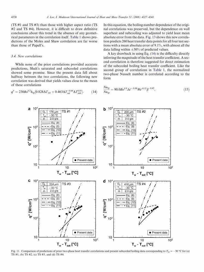
4338 J. Lee, I. Mudawar / International Journal of Heat and Mass Transfer 51 (2008) 4327–4341
(TS #1 and TS #3) than those with higher aspect ratio (TS#2 and TS #4). However, it is difficult to draw definitiveconclusions about this trend in the absence of any geomet-rical parameters in the correlation itself. Table 1 shows pre-dictions of the Moles and Shaw correlation are far worsethan those of Papell’s.
3.4. New correlations
While none of the prior correlations provided accuratepredictions, Shah’s saturated and subcooled correlationsshowed some promise. Since the present data fell abouthalfway between the two correlations, the following newcorrelation was derived that yields values close to the meanof these correlations
q00 ¼ 230Bo0:5hsp½0:828DT sat þ 0:463DT�0:04sat DT 0:81
sub �: ð14Þ
Fig. 11. Comparison of predictions of prior two-phase heat transfer correlationTS #1, (b) TS #2, (c) TS #3, and (d) TS #4.
In this equation, the boiling number dependence of the origi-nal correlations was preserved, but the dependence on wallsuperheat and subcooling was adjusted to yield least meanabsolute error from the data. Fig. 13 shows this new correla-tion predicts 260 heat transfer data points for all four test sec-tions with a mean absolute error of 9.1%, with almost all thedata falling within ±30% of predicted values.
A key drawback in using Eq. (14) is the difficulty directlyinferring the magnitude of the heat transfer coefficient. A sec-ond correlation is therefore suggested for direct estimationof the subcooled boiling heat transfer coefficient. Like thesecond group of correlations in Table 1, the normalizedtwo-phase Nusselt number is correlated according to theform
Nutp
Nusp
¼ 90:0Bo0:9Ja��0:98We�0:15b�0:42; ð15Þ
s and present subcooled boiling data corresponding to Tin = �30 �C for (a)

Fig. 12. Comparison of predictions of Papell’s correlation and present subcooled boiling data.
Fig. 13. Comparison of predictions of new modified Shah correlation and subcooled boiling data for four test sections.
J. Lee, I. Mudawar / International Journal of Heat and Mass Transfer 51 (2008) 4327–4341 4339
where
Ja� ¼ cp;fDT sub;in
hfg
; We� ¼ G2Dh
ðqf � qgÞr; and b ¼ H ch
W ch
:
ð16Þ
Unlike earlier correlations, Eq. (15) accounts for all rel-evant physical parameters of subcooled flow boiling inmicro-channels. The effects of heat flux, inlet subcooling,surface tension and geometry are accounted for in fourrespective dimensionless groups: boiling number, Jacob

Fig. 14. Comparison of predictions of new normalized two-phase Nusselt number correlation and experimental data for four test sections.
4340 J. Lee, I. Mudawar / International Journal of Heat and Mass Transfer 51 (2008) 4327–4341
number, Weber number and channel aspect ratio. Fig. 14compares the predictions of this new correlation withexperimental data for the four test sections. Althoughthe mean absolute error for this correlation is greaterthan for Eqs. (14, 15), enables direct calculation of thetwo-phase heat transfer coefficient as well as accountsfor all the parameters that were shown in part 1 of thisstudy to influence cooling performance.
4. Conclusions
Experiments were performed to determine both thepressure drop and heat transfer characteristics of two-phase micro-channel flow. Unlike earlier studies of two-phase heat sinks, where annular evaporation is typicallythe dominant mechanism for heat removal, the presentwork focused on subcooled boiling characteristics. Fourdifferent test sections were tested to assess the effects ofnot only hydraulic diameter, but micro-channel widthand aspect ratio as well. Aided by findings from the flowvisualization study presented in part 1, the data werecarefully examined for important parametric trends andcompared to predictions of earlier correlations. Key find-ings from this study are as follows.
(1) During single-phase cooling, pressure drop decreaseswith increasing heat flux because of decreased liquidviscosity. After bubbles form and depart into theliquid flow, void fraction begins to increase appre-ciably, causing pressure drop to begin increasing
with increasing heat flux. These opposite trends pro-duce a minimum in the variation of pressure dropwith heat flux.
(2) Increasing the subcooling of incoming liquiddecreases two-phase pressure drop because ofdecreased void fraction caused by strong condensa-tion at bubble interfaces, and decreased likelihoodof bubble coalescence.
(3) The effects of hydraulic diameter on two-phase heattransfer are complicated by the relative size of bub-bles and micro-channel width. While smaller hydrau-lic diameters tend to enhance two-phase coolingperformance by increasing both mass velocity andwetted area, smaller micro-channel width can triggerearly transition from bubbly to slug flow, causing areduction in cooling effectiveness.
(4) It is quite difficult to identify correlations from theheat transfer literature that can predict pressure dropand cooling behavior of subcooled micro-channelheat sinks. This difficulty is the result of scarcity ofsubcooled boiling correlations in general, and thedrastic differences in fluid, hydraulic diameter, andoperating conditions of the present study comparedto the macro-channel heat transfer databases uponwhich these correlations are based. Two new modi-fied forms of earlier correlations produced good pre-dictions of the present heat transfer data.
(5) The shortage of useful correlations highlights theneed for new mechanistic models of subcooledmicro-channel boiling that capture the complex inter-

J. Lee, I. Mudawar / International Journal of Heat and Mass Transfer 51 (2008) 4327–4341 4341
facial interactions reported in part 1 of this study.Such models are the goals of ongoing studies by theauthors.
Acknowledgement
The authors are grateful for the support of the Office ofNaval Research (ONR) for this study.
References
[1] J. Lee, I. Mudawar, Fluid flow and heat transfer characteristics of lowtemperature two-phase micro-channel heat sinks – Part 1. Experi-mental methods and flow visualization results, Int. J. Heat MassTransfer, in press, doi:10.1016/j.ijheatmasstransfer.2008.02.012.
[2] D.B. Tuckerman, R.F.W. Pease, High-performance heat sinking forVLSI, IEEE Electron. Devices Lett. 2 (1981) 126–129.
[3] I. Mudawar, M.A. El-Masri, C.S. Wu, J.R. Ausman-Mudawar,Boiling heat transfer and critical heat flux in high-speed rotatingliquid films, Int. J. Heat Mass Transfer 28 (1985) 795–806.
[4] M.B. Bowers, I. Mudawar, High flux boiling in low flow rate, lowpressure drop mini-channel and micro-channel heat sinks, Int. J. HeatMass Transfer 37 (1994) 321–332.
[5] M.B. Bowers, I. Mudawar, Two-phase electronic cooling using mini-channel and micro-channel heat sinks: Part 1 – Design criteria andheat diffusion constraints, ASME J. Electron. Packaging 116 (1994)290–297.
[6] M.B. Bowers, I. Mudawar, Two-phase electronic cooling usingmini-channel and micro-channel heat sinks: Part 2 – Flow rate andpressure drop constraints, ASME J. Electron. Packaging 116 (1994)298–305.
[7] I. Mudawar, M.B. Bowers, Ultra-high critical heat flux (CHF) forsubcooled water flow boiling – I. CHF data and parametric effects forsmall diameter tubes, Int. J. Heat Mass Transfer 42 (1999) 1405–1428.
[8] H.J. Lee, S.Y. Lee, Heat transfer correlation for boiling flows in smallrectangular horizontal channels with low aspect ratios, Int. J.Multiphase Flow 27 (2001) 2043–2062.
[9] H.J. Lee, S.Y. Lee, Pressure drop correlations for two-phase flowwithin horizontal rectangular channels with small heights, Int. J.Multiphase Flow 27 (2001) 783–796.
[10] W. Yu, D.M. France, M.W. Wambsganss, J.R. Hull, Two-phasepressure drop, boiling heat transfer, and critical heat flux to water in asmall-diameter horizontal tube, Int. J. Multiphase Flow 28 (2002)927–941.
[11] W. Qu, I. Mudawar, Prediction and measurement of incipient boilingheat flux in micro-channel heat sinks, Int. J. Heat Mass Transfer 45(2002) 3933–3945.
[12] W. Qu, I. Mudawar, Measurement and prediction of pressure drop intwo-phase micro-channel heat sinks, Int. J. Heat Mass Transfer 46(2003) 2737–2753.
[13] W. Qu, I. Mudawar, Flow boiling heat transfer in two-phase micro-channel heat sinks – I. Experimental investigation and assessment ofcorrelation methods, Int. J. Heat Mass Transfer 46 (2003) 2755–2771.
[14] W. Qu, I. Mudawar, Flow boiling heat transfer in two-phase micro-channel heat sinks – II. Annular two-phase flow model, Int. J. HeatMass Transfer 46 (2003) 2773–2784.
[15] J. Lee, I. Mudawar, Two-phase flow in high-heat-flux micro-channelheat sink for refrigeration cooling applications: Part I. Pressure dropcharacteristics, Int. J. Heat Mass Transfer 48 (2005) 928–940.
[16] J. Lee, I. Mudawar, Two-phase flow in high-heat-flux micro-channelheat sink for refrigeration cooling applications: Part II. Heat transfercharacteristics, Int. J. Heat Mass Transfer 48 (2005) 941–955.
[17] I. Mudawar, Assessment of high-heat-flux thermal managementschemes, IEEE Trans. – CPMT: Components and Packaging Tech-nologies 24 (2001) 122–141.
[18] J.G. Collier, J.R. Thome, Convective Boiling and Condensation, 3rded., Oxford University Press, New York, 1994, pp. 183–213.
[19] W. Tong, A.E. Bergles, M.K. Jensen, Pressure drop with highlysubcooled flow boiling in small-diameter tubes, Exp. Therm. FluidSci. 15 (1997) 202–212.
[20] P. Saha, N. Zuber, Point of net vapor generation and vapor voidfraction in subcooled boiling, in: Heat Transfer 1974, vol. 4,Proceedings of the 5th International Heat Transfer Conference,Tokyo, 1974, pp. 175–179.
[21] M.A. Hoffman, C.T. Kline, Evaluation of several empirical modelsfor predicting subcooled flow-boiling pressure drop, in: V.K. Dhir,J.C. Chen, O.C. Jones (Eds.), Multiphase Flow and Heat Transfer,23rd National Heat Transfer Conference, ASME HTD, vol. 47,Denver, CO, 1985, pp. 151–160.
[22] M.A. Hoffman, C.F. Wong, Prediction of pressure drops in forcedconvection subcooled boiling water flows, Int. J. Heat Mass Transfer35 (1992) 3291–3299.
[23] W.K. Kays, M.E. Crawford, Convective Heat and Mass Transfer,2nd ed., McGraw-Hill, New York, 1980, pp. 275–280.
[24] A.E. Bergles, T. Dormer Jr., Subcooled boiling pressure drop withwater at low pressure, Int. J. Heat Mass Transfer 12 (1969) 459–470.
[25] M.M. Shah, A new correlation for heat transfer during boiling flowthrough pipes, ASHRAE Trans. 82 (1976) 66–86.
[26] M.M. Shah, A general correlation for heat transfer during subcooledboiling in pipes and annuli, ASHRAE Trans. 83 (1977) 202–217.
[27] S.G. Kandlikar, A general correlation for saturated two-phase flowboiling heat transfer inside horizontal and vertical tubes, ASME J.Heat Transfer 112 (1990) 219–228.
[28] S.G. Kandlikar, Heat transfer characteristics in partial boiling, fullydeveloped boiling, and significant void flow regions of subcooled flowboiling, ASME J. Heat Transfer 120 (1998) 395–401.
[29] S.S. Papell, Subcooled boiling heat transfer under forced convectionin a heated tube, NASA Technical Note D-1583, Lewis ResearchCenter, Cleveland, OH, 1963.
[30] F.D. Moles, J.F.G. Shaw, Boiling heat transfer to subcooled liquidsunder condition of forced convection, Trans. Inst. Chem. Eng. 50(1972) 76–84.