lecture 2 faults, errors, failures - Åbo akademi |...
TRANSCRIPT
Lecture 2 Faults, errors, failures
But the example is idealistic…
• Because it controls a fault-free system • A fault-free system would operate perfectly! • But faults are inevitable!!!
Fault
• Fault is a defect within the system • Examples:
– Software bug – Random hardware fault – Memory bit “stuck” – Omission or commission fault in data transfer – Etc.
Error • Error is a deviation from the required operation of
system or subsystem • A fault may lead to an error, i.e., error is a
mechanism by which the fault becomes apparent • Fault may stay dormant for a long time before it
manifests itself as an error: • Example:
– memory bit got stuck but CPU does not access this data – Software “bug” in a subroutine is not “visible” while the
subroutine is not called
Failure
• A system failure occurs when the system fails to perform its required function
• Presence of an error might cause a whole system to deviate from its required operation
• One of the goals of safety-critical systems is that error should not result in system failure
Hardware failures: random faults
• Random faults are associated with hardware components
• All physical components are subject to failure all systems are subject to random faults
Random faults
• When working within their correct operating environment, individual components fail randomly
• We can – gather statistical data on large number of similar devices – Make prediction of the probability of a component failing
within a given period of time – Use it to predict the overall performance of the system
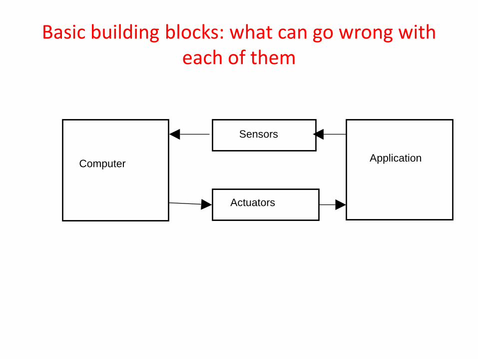
Basic building blocks: what can go wrong with each of them
Computer
Sensors
Actuators
Application
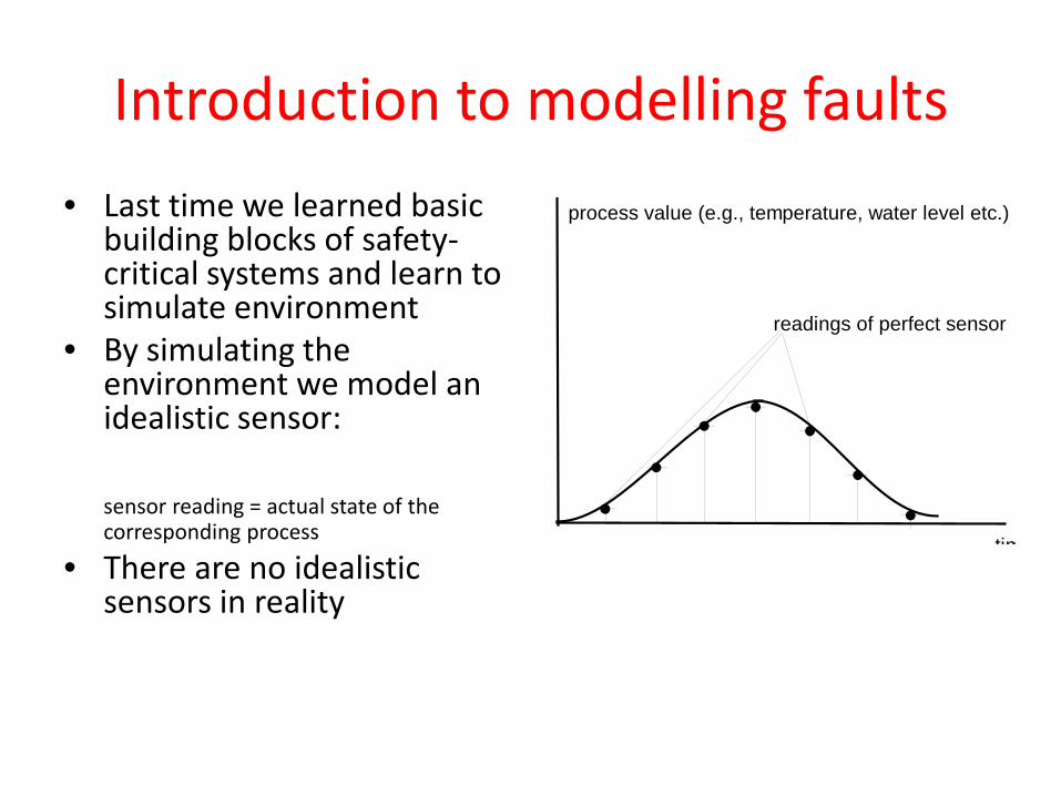
Introduction to modelling faults • Last time we learned basic
building blocks of safety-critical systems and learn to simulate environment
• By simulating the environment we model an idealistic sensor:
sensor reading = actual state of the corresponding process
• There are no idealistic sensors in reality
tim
process value (e.g., temperature, water level etc.)
readings of perfect sensor
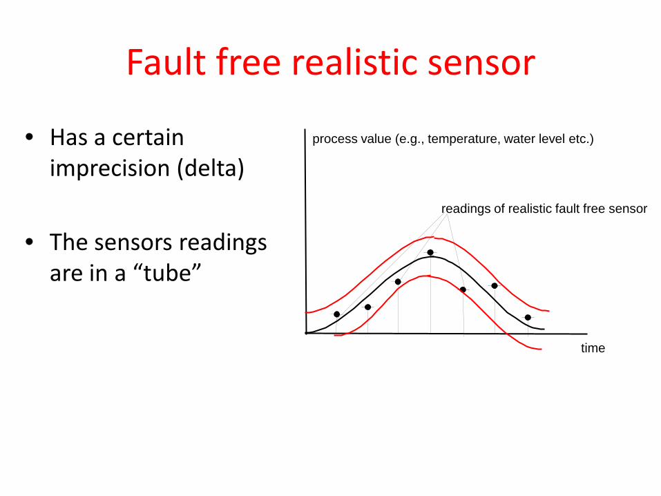
Fault free realistic sensor
• Has a certain imprecision (delta)
• The sensors readings are in a “tube” time
process value (e.g., temperature, water level etc.)
readings of realistic fault free sensor
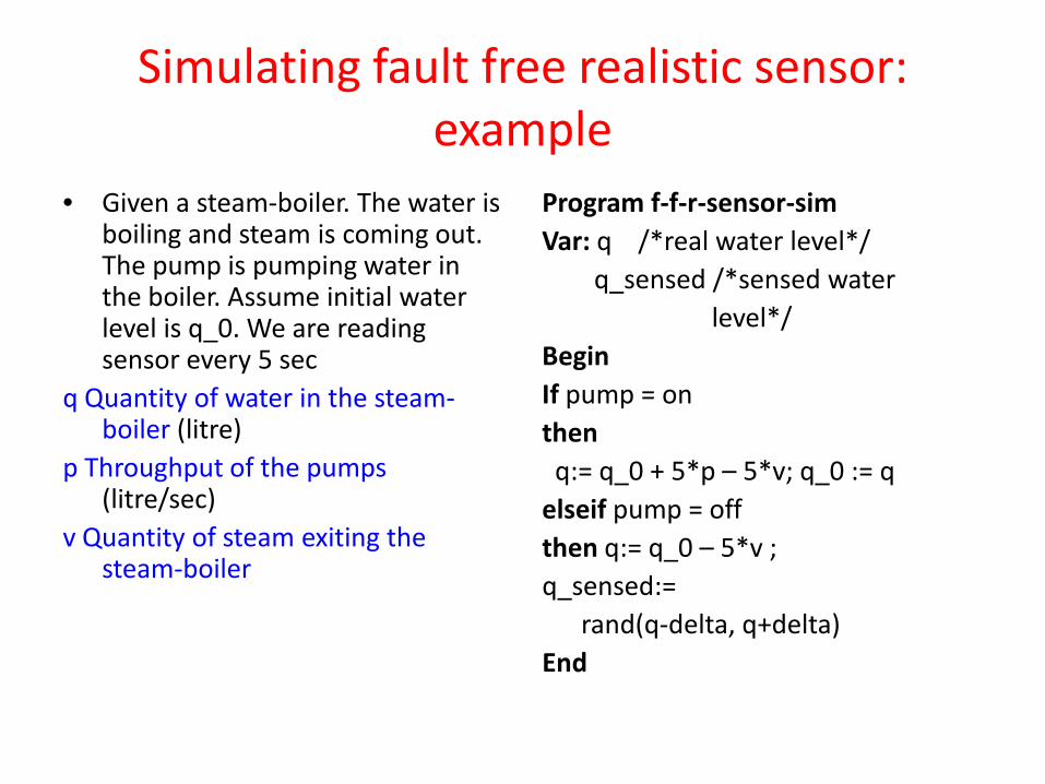
Simulating fault free realistic sensor: example
• Given a steam-boiler. The water is boiling and steam is coming out. The pump is pumping water in the boiler. Assume initial water level is q_0. We are reading sensor every 5 sec
q Quantity of water in the steam-boiler (litre)
p Throughput of the pumps (litre/sec)
v Quantity of steam exiting the steam-boiler
Program f-f-r-sensor-sim Var: q /*real water level*/ q_sensed /*sensed water level*/ Begin If pump = on then q:= q_0 + 5*p – 5*v; q_0 := q elseif pump = off then q:= q_0 – 5*v ; q_sensed:= rand(q-delta, q+delta) End
A general principle of simulating fault free sensors
• Model a random sample within the “tube” around the physical process (but do not forget that you need to model the physical process itself too)
• When you model “switch type” sensor keep in mind that it will change its value not exactly at the threshold but in delta area around it
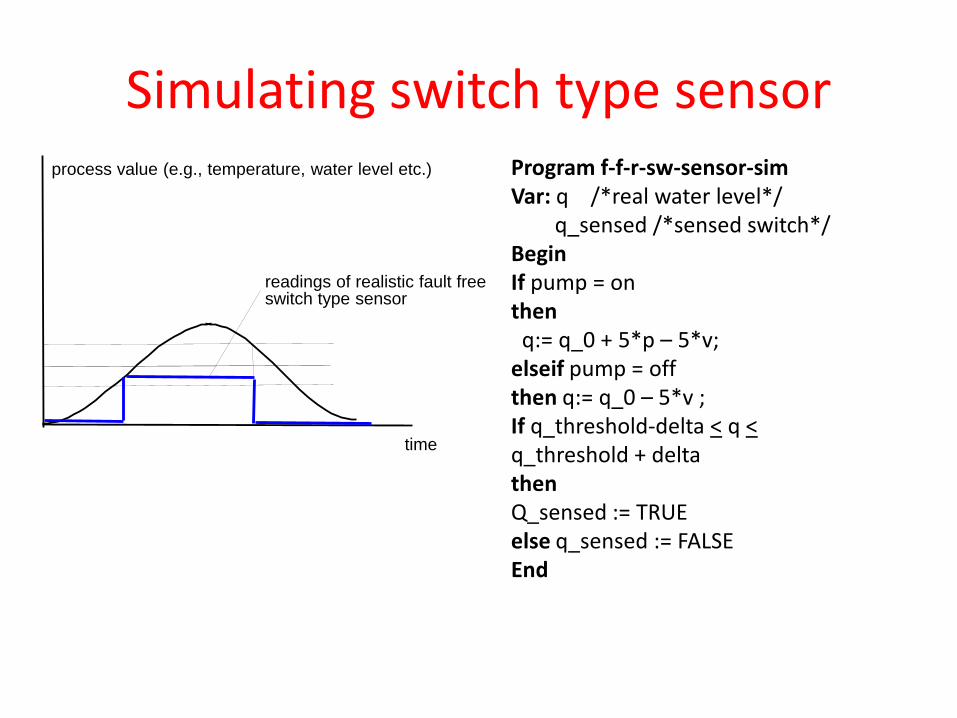
Simulating switch type sensor
time
process value (e.g., temperature, water level etc.)
readings of realistic fault free switch type sensor
Program f-f-r-sw-sensor-sim Var: q /*real water level*/ q_sensed /*sensed switch*/ Begin If pump = on then q:= q_0 + 5*p – 5*v; elseif pump = off then q:= q_0 – 5*v ; If q_threshold-delta < q < q_threshold + delta then Q_sensed := TRUE else q_sensed := FALSE End
Failure modes of sensors
• Sensor fails when it produces an incorrect signal for a given stimulus
• Often are characterized by time response characteristics – Permanent – Offset – Erratic – Intermittent – Transient
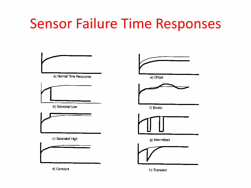
Sensor Failure Time Responses
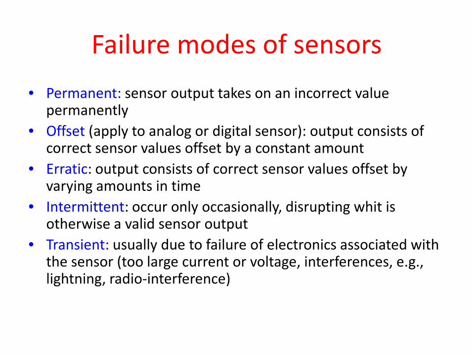
Failure modes of sensors • Permanent: sensor output takes on an incorrect value
permanently • Offset (apply to analog or digital sensor): output consists of
correct sensor values offset by a constant amount • Erratic: output consists of correct sensor values offset by
varying amounts in time • Intermittent: occur only occasionally, disrupting whit is
otherwise a valid sensor output • Transient: usually due to failure of electronics associated with
the sensor (too large current or voltage, interferences, e.g., lightning, radio-interference)
Explanation of some failure modes of digital or analog sensors
• Minimum output : output maintains lowest possible signal level
• Maximum output: output maintains highest possible signal level
• Constant output: output does not change when input changes
Explanation of some failure modes of discrete level and discrete switch
Discrete level • Intermittent switches intermittently between high
and low level • Spurious switch: switches with no input • Fails to switch : fails to switch when input changes Discrete Switch • Switch at wrong level: switches when input stimulus
is at an incorrect value • Fails to switch…
Sensor failure effect
• Since little or no energy involved, sensor failures by themselves are usually quite harmless.
• However, • Sensor data is processes by the controller to
generate signals that change state of actuators. Hence if sensor faults are undetected failure of the system can occur
Why did we learn it?
• Because detection of faults is usually done by controlling software. So we should “learn our enemy”
• In the course we will consider only very simple permanent faults such as maximum output, minimum output, fails to switch
Actuators
• An actuators fails when it produces an incorrect stimulus for a given input signal
• Examples of sensor’s failures: • Hydraulic valve: leaking, stuck closed, stuck
open. • Electric motor: fails to start, suddenly stops
Effect of actuators failures
• Actuators can generate considerable amounts of mechanical and electrical power in their output.
• Actuators failures can by themselves produce damage, injury, etc.
• Because actuators control energy and material movement they failures can be direct cause of accident
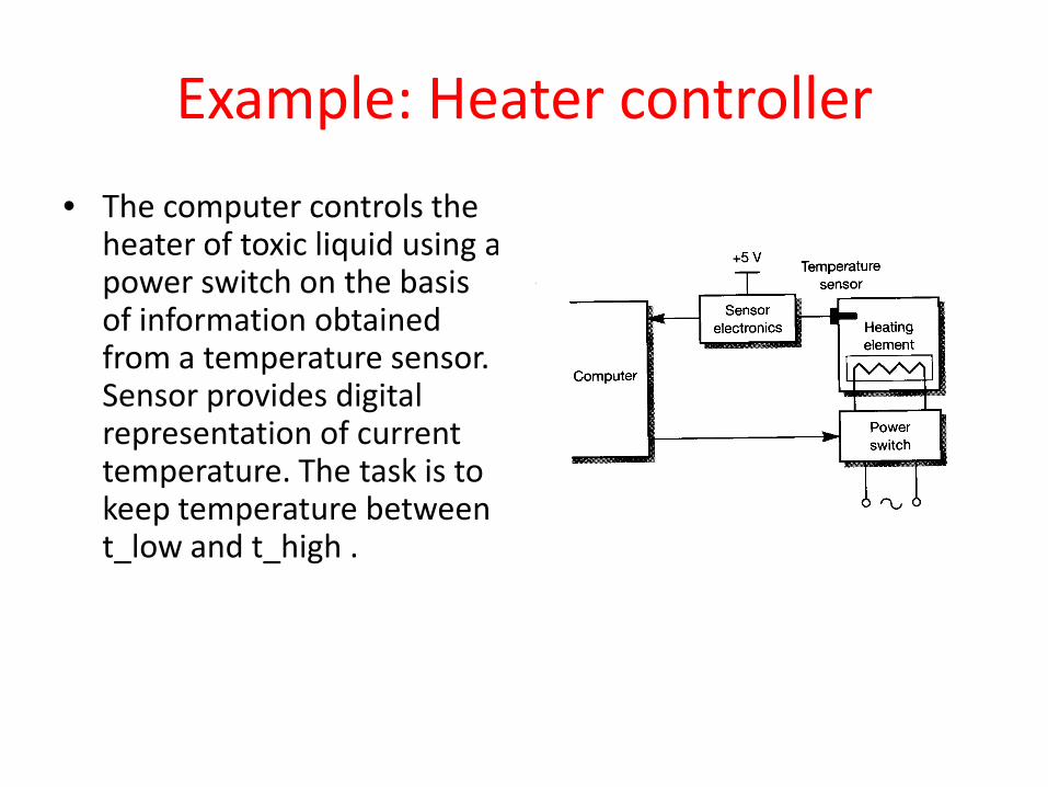
Example: Heater controller • The computer controls the
heater of toxic liquid using a power switch on the basis of information obtained from a temperature sensor. Sensor provides digital representation of current temperature. The task is to keep temperature between t_low and t_high .
Structure of the heater controller
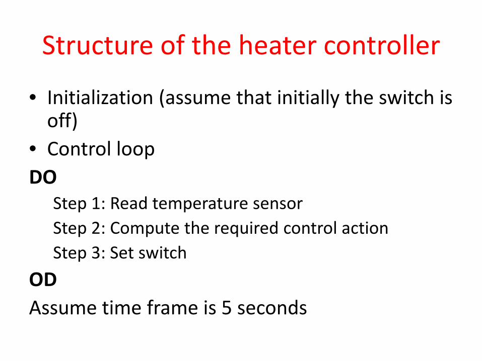
• Initialization (assume that initially the switch is off)
• Control loop DO
Step 1: Read temperature sensor Step 2: Compute the required control action Step 3: Set switch
OD Assume time frame is 5 seconds
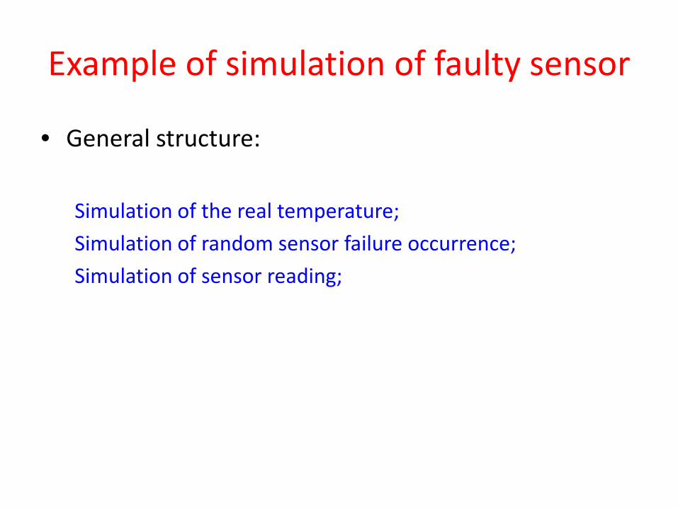
Example of simulation of faulty sensor
• General structure: Simulation of the real temperature; Simulation of random sensor failure occurrence; Simulation of sensor reading;
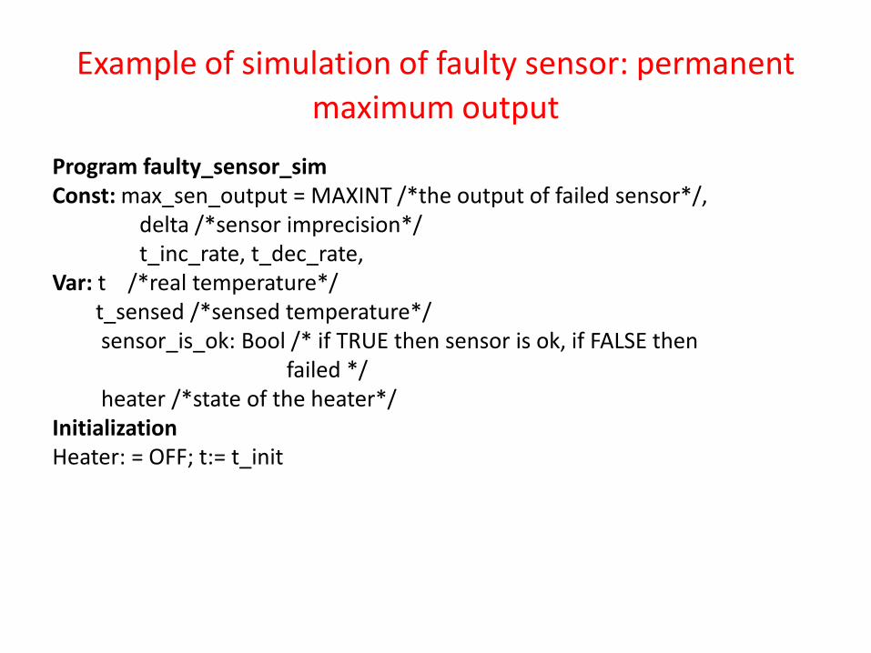
Example of simulation of faulty sensor: permanent maximum output
Program faulty_sensor_sim Const: max_sen_output = MAXINT /*the output of failed sensor*/, delta /*sensor imprecision*/ t_inc_rate, t_dec_rate, Var: t /*real temperature*/ t_sensed /*sensed temperature*/ sensor_is_ok: Bool /* if TRUE then sensor is ok, if FALSE then failed */ heater /*state of the heater*/ Initialization Heater: = OFF; t:= t_init
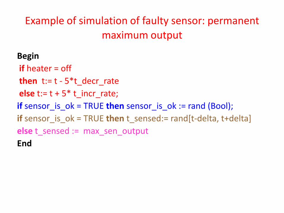
Example of simulation of faulty sensor: permanent maximum output
Begin if heater = off then t:= t - 5*t_decr_rate else t:= t + 5* t_incr_rate; if sensor_is_ok = TRUE then sensor_is_ok := rand (Bool); if sensor_is_ok = TRUE then t_sensed:= rand[t-delta, t+delta] else t_sensed := max_sen_output End
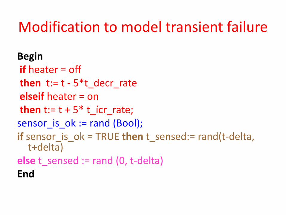
Modification to model transient failure
Begin if heater = off then t:= t - 5*t_decr_rate elseif heater = on then t:= t + 5* t_ícr_rate; sensor_is_ok := rand (Bool); if sensor_is_ok = TRUE then t_sensed:= rand(t-delta,
t+delta) else t_sensed := rand (0, t-delta) End
Note
• Please remember that the controller does not “see” t (i.e., cannot read t)!
• Controller gets only t_sensed.