learning to be a depth camera for close-range human capture and interaction
TRANSCRIPT
ACM Reference FormatFanello, S., Keskin, C., Izadi, S., Kohli, P., Kim, D., Sweeney, D., Criminisi, A., Shotton, J., Kang, S., Paek, T. 2014. Learning to be a Depth Camera for Close-Range Human Capture and Interaction. ACM Trans. Graph. 33, 4, Article 86 (July 2014), 11 pages. DOI = 10.1145/2601097.2601223 http://doi.acm.org/10.1145/2601097.2601223.
Copyright NoticePermission to make digital or hard copies of all or part of this work for personal or classroom use is granted without fee provided that copies are not made or distributed for profi t or commercial advantage and that copies bear this notice and the full citation on the fi rst page. Copyrights for components of this work owned by others than the author(s) must be honored. Abstracting with credit is permitted. To copy otherwise, or re-publish, to post on servers or to redistribute to lists, requires prior specifi c permission and/or a fee. Request permissions from [email protected] Copyright held by the Owner/Author. Publication rights licensed to ACM. 0730-0301/14/07-ART86 $15.00.DOI: http://dx.doi.org/10.1145/2601097.2601223
Learning to be a Depth Camerafor Close-Range Human Capture and Interaction
Sean Ryan Fanello1,2 Cem Keskin1 Shahram Izadi1 Pushmeet Kohli1 David Kim1 David Sweeney1
Antonio Criminisi1 Jamie Shotton1 Sing Bing Kang1 Tim Paek1
1Microsoft Research 2iCub Facility - Istituto Italiano di Tecnologia
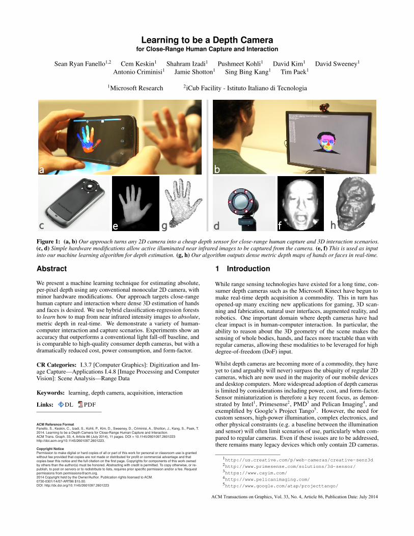
a b
c de fg h
Figure 1: (a, b) Our approach turns any 2D camera into a cheap depth sensor for close-range human capture and 3D interaction scenarios.(c, d) Simple hardware modifications allow active illuminated near infrared images to be captured from the camera. (e, f) This is used as inputinto our machine learning algorithm for depth estimation. (g, h) Our algorithm outputs dense metric depth maps of hands or faces in real-time.
Abstract
We present a machine learning technique for estimating absolute,per-pixel depth using any conventional monocular 2D camera, withminor hardware modifications. Our approach targets close-rangehuman capture and interaction where dense 3D estimation of handsand faces is desired. We use hybrid classification-regression foreststo learn how to map from near infrared intensity images to absolute,metric depth in real-time. We demonstrate a variety of human-computer interaction and capture scenarios. Experiments show anaccuracy that outperforms a conventional light fall-off baseline, andis comparable to high-quality consumer depth cameras, but with adramatically reduced cost, power consumption, and form-factor.
CR Categories: I.3.7 [Computer Graphics]: Digitization and Im-age Capture—Applications I.4.8 [Image Processing and ComputerVision]: Scene Analysis—Range Data
Keywords: learning, depth camera, acquisition, interaction
Links: DL PDF
1 Introduction
While range sensing technologies have existed for a long time, con-sumer depth cameras such as the Microsoft Kinect have begun tomake real-time depth acquisition a commodity. This in turn hasopened-up many exciting new applications for gaming, 3D scan-ning and fabrication, natural user interfaces, augmented reality, androbotics. One important domain where depth cameras have hadclear impact is in human-computer interaction. In particular, theability to reason about the 3D geometry of the scene makes thesensing of whole bodies, hands, and faces more tractable than withregular cameras, allowing these modalities to be leveraged for highdegree-of-freedom (DoF) input.
Whilst depth cameras are becoming more of a commodity, they haveyet to (and arguably will never) surpass the ubiquity of regular 2Dcameras, which are now used in the majority of our mobile devicesand desktop computers. More widespread adoption of depth camerasis limited by considerations including power, cost, and form-factor.Sensor miniaturization is therefore a key recent focus, as demon-strated by Intel1, Primesense2, PMD3 and Pelican Imaging4, andexemplified by Google’s Project Tango5. However, the need forcustom sensors, high-power illumination, complex electronics, andother physical constraints (e.g. a baseline between the illuminationand sensor) will often limit scenarios of use, particularly when com-pared to regular cameras. Even if these issues are to be addressed,there remains many legacy devices which only contain 2D cameras.
1http://us.creative.com/p/web-cameras/creative-senz3d2http://www.primesense.com/solutions/3d-sensor/3https://www.cayim.com/4http://www.pelicanimaging.com/5http://www.google.com/atap/projecttango/
ACM Transactions on Graphics, Vol. 33, No. 4, Article 86, Publication Date: July 2014
In this paper, we describe a very cost-effective depth sensing systemwhich, for specific acquisition and interaction scenarios, can turna regular 2D monocular camera into a depth sensor. Specifically,we devise an algorithm that learns the correlation between pixelintensities and absolute depth measurements. The algorithm is im-plemented on conventional color or monochrome cameras. The onlyhardware modifications required are: i) the removal of any nearinfrared (NIR) cut filter (typically used in regular RGB sensors), andii) the addition of an bandpass filter and low-cost/power LEDs (bothoperating in a narrow NIR range).
There has been much progress in the fields of lighting-based geom-etry estimation and shape-from-shading ([Horn 1975; Zhang et al.1999]). However, the problem is fundamentally ill-posed due to theunknown varying surface geometry and reflectance, and traditionalapproaches often resort to explicit assumptions, such as carefulcamera and illuminant calibration, known surface reflectance, orgeometry (e.g., [Vogel et al. 2009]). Even so, achieving precisedense depth measurements remains challenging.
We instead take a data-driven machine learning approach, for thespecific scenario of capturing the geometry of hands and faces.We propose to use hybrid classification-regression forests to learna direct mapping from NIR intensity images to absolute, metricdepth, for these specific scenarios. The forest automatically learnsto associate a depth value with a pixel, based on its intensity in theNIR range, and the intensities of its neighboring pixels. The use of alearned model of spatial context is key to produce naturally smoothdepth images which preserve transitions at occlusion boundaries.
We train our system using either synthetically rendered intensity im-ages and associated ground truth depth maps; or a calibrated physicalrig, where depth maps (captured using a high quality depth camera)are registered with intensity images acquired from our modifiedcamera. The data (and thus the learned model) implicitly encodesinformation about the subject’s surface geometry and reflectance,the camera intrinsics, vignetting effects, and the active and ambientilluminants. Our forest models are learned using a small set of sub-jects and camera devices. However, even with limited training datacaptured at low-effort, we demonstrate that our models are able togeneralize well, even across subjects and devices.
Our use of decision forests yields an efficient algorithm which runs inreal-time on portable devices. We validate our algorithm for human-computer interaction applications, and compare quantitatively withboth existing high-quality consumer depth cameras and standardlight fall-off techniques. Our algorithm enables us to turn practicallyany camera into a real-time depth camera for close-range humancapture and interaction scenarios, without high power consumption,bulk, and expense. Whilst not a general purpose depth camera, ithas the potential to enable a wide variety of new applications formobile and desktop 3D interaction and acquisition.
In summary, our paper makes the following contributions:
• We demonstrate a new technique for turning a cheap color ormonochrome camera into a depth sensor, for close-range hu-man capture and interaction. Our hope is to allow practitionersto more rapidly prototype depth-based applications in a varietyof new contexts.
• We present two practical hardware designs for depth sensing:(i) a modified web camera for desktop depth sensing, and(ii) a modified cellphone camera for mobile applications. Wedemonstrate efficient and accurate hand and face tracking inboth scenarios.
• We propose specializations of existing multi-layered decisionforests algorithms for the task of depth prediction which canachieve 100Hz performance on commodity hardware.
• We present experimental and real-world results that illustratedepth estimation accuracies for our specific scenarios that arecomparable to state of the art consumer depth cameras.
2 Related Work
Many different depth sensing approaches have been proposed overthe last few decades. Here we briefly cover relevant techniques; see[Besl 1988; Batlle et al. 1998; Zhang et al. 1999; Scharstein andSzeliski 2002; Blais 2004; Lanman and Taubin 2009] for detailedreviews.
Depth from Passive Stereo: Given images captured from two ormore displaced RGB cameras, stereo methods identify points thatare projections of the same 3D scene point. The point depth is re-lated to the displacements of its image projections. Many algorithmshave been proposed, including real-time methods [Scharstein andSzeliski 2002; Brown et al. 2003]. The biggest limitation of such ap-proaches is that textureless regions yield inherent depth ambiguities.This results in incorrect depth estimates, or the need for expensiveregularization or post-processing.
Structured Light and Active Stereo: The problem of texturelessregions can be mitigated with the use of structured illumination (seee.g. [Besl 1988; Batlle et al. 1998; Blais 2004; Zhang 2010]). Manyexample of coded patterns exists, ranging from dynamic temporalsequences to single fixed patterns. Systems either employ two cam-eras plus illumination source, or use a single camera and calibratedprojector to perform 3D triangulation. Even in these systems prob-lems remain when estimating depths at object boundaries, wherelarge depth discontinuities lead to outliers, holes, and edge fattening[Scharstein and Szeliski 2002; Brown et al. 2003]. Additionally allsetups require a distance between projector and camera, and requirea high-quality and costly/complex illumination source.
The Primesense (Kinect) camera projects a pseudo-random dot pat-tern and uses a displaced custom NIR sensor to triangulate depth. Itdemonstrates reasonably small form-factor and reduced cost. How-ever, a high quality single-mode laser, diffractive optical element(DOE), high-resolution (1280x960) NIR camera, thermoelectricalcooling, and baseline between emitter and sensor are required. Ourmethod uses any cheap modified 2D camera and simple LED-basedillumination, without the need for a baseline. This allows legacydevices to be turned into depth cameras, but only for specific human-interaction scenarios.
Time of Flight: Many other depth sensing techniques exist beyondtriangulation-based methods. Time-of-flight (ToF) cameras eithermodulate NIR lasers/LEDs and look at the shift in phase of thereturn signal (often referred to as continuous-mode devices), or usehigh frequency (physical or electronic) shutters in front of the imagesensor to gate the returning pulses of light according to its time ofarrival (often referred to as shuttered or gated devices). Almostall devices, including the recent Xbox One sensor6 work on thecontinuous-mode principle. Shuttered devices are rarer, but includethe legacy ZCam from 3DV7. Whilst the principle of ToF is usedin precise measurement for expensive laser range finders (whichgive a single range measurement at a time), full frame ToF camerastypically suffer from high noise, including depth jitter and mixedpixels [Remondino and Stoppa 2013], and require costly customsensors and electronics.
Geometry Estimation from Intensity Images: In terms of hard-ware, a cheaper method to acquire the 3D shape of an object is to useshape-from-shading (SFS) where the naturally occurring intensity
6http://www.xbox.com/en-GB/xbox-one/innovation7http://en.wikipedia.org/wiki/ZCam
86:2 • S. R. Fanello et al.
ACM Transactions on Graphics, Vol. 33, No. 4, Article 86, Publication Date: July 2014
patterns across an image are used to extract the 3D geometry froma single image [Horn 1975; Zhang et al. 1999]. The mathematicsof SFS is well-understood particularly when surface reflectance andlight source position is known. [Prados and Faugeras 2005] recon-struct various objects including faces, using a light source at thecenter of the camera. [Ahmed and Farag 2007] demonstrate geome-try estimation for non-Lambertian surfaces and varying illuminationconditions. [Visentini-Scarzanella et al. 2012] exploit an off-axislight source, specularities and SFS for metric reconstruction.
Whilst the physics of SFS is well known, the problem is inherentlyill-posed, and achieving compelling results requires strong scene andlighting assumptions and computationally complex algorithms. Assuch, real-time performance has rarely been demonstrated. This hasled to work on photometric stereo where multiple images of a sceneare captured under different controlled illumination to compute ge-ometry. Photometric stereo has demonstrated extremely compellingresults including reconstruction of surfaces with complex reflectanceproperties [Mulligan and Brolly 2004; Hernandez et al. 2008; Ghoshet al. 2011; Tunwattanapong et al. 2013], as well as mobile uses8.However, these approaches can require complex lighting setups, alarge baseline between light sources and camera, and/or sequentialcapture with changing illumination direction (although colored lightscan allow for single frame multi-channel capture [Hernandez et al.2008]). These constraints make real-time dynamic scene capture onself-contained mobile devices challenging.
Related systems exploit the inverse square law to estimate depthfrom light fall-off. [Liao et al. 2007; Gurbuz 2009; Liu et al. 2011]capture images of the scene, with a fixed camera and light sourcesat varying distances, and measure depth from intensity differences.The Cyclops camera from Dinast9 and the Digits system [Kim et al.2012] uses a simpler light fall-off approximation for estimatingcoarse, relative depth per frame. Light fall-off measurements areinfluenced by surface albedo and geometry, ambient light and objectinter-reflections, all of which lead to low-quality depth estimation.Often careful calibration of light source and camera is required,and/or multiple captures of the scene are needed under varyingillumination; again making interactive mobile scenarios challenging.
Learning-based and Statistical Methods: Given these challenges,more data-driven approaches to solving the SFS problem have beenproposed. [Barron and Malik 2013] jointly solve for reflectance,shape and illumination, based on priors derived statistically fromimages. Our approach does not impose strong priors on shape re-covery. [Khan et al. 2009] learn weighting parameters for complexSFS models to aid facial reconstruction. [Wei and Hirzinger 1996;Ben-Arie and Nandy 1998; Jiang et al. 2003] use deep neural net-works to learn aspects of the physical model for SFS, demonstratingmoderate results for very constrained scenes.
Other learning-based approaches operate on single color images ofoutdoor environments; for example, [Hoiem et al. 2005] extractsregions based on identity (‘sky’, ‘ground’, ‘vertical’), and estimatesdepth coarsely. The technique of [Saxena et al. 2009; Karsch et al.2012] relies on training depth cues and spatial relationships basedon ground-truth image-depth pairs, but again only derives coarsedepth. Whilst these approaches are closest to our work, none of thispast work has demonstrated real-time performance, or the abilityto smoothly infer absolute pixel-wise depth for video sequences.Real-time 2D-to-3D conversion techniques do exist, but they tend torely on fragile video cues [Ideses et al. 2007]. Other approaches uselearning for material and BRDF estimation [Hertzmann and Seitz2005; Rother et al. 2011; Vineet et al. 2013], but do not directlyaddress real-time depth prediction given intensity images.
8http://www.trimensional.com9http://www.dinast.com
Other related approaches fit face and human body models to singleimages using statistical shape models e.g., [Guan et al. 2009; Blanzand Vetter 1999; Wang and Yang 2010]. [Smith and Hancock 2008]use a statistically derived SFS model specifically for facial recon-struction. In our work, we do not rely on specific global geometricmodels or shape priors for depth recovery.
Near-Infrared Imaging: Our approach can be thought of as anextension to SFS, where the problem is made tractable by focusingon dense and accurate depth prediction of human hands and faces(which is particularly important for interactive scenarios) and us-ing controlled near-infared (NIR) based illumination with a simplecamera modification.
Prior work and amateur photographers have exploited the fact thatdigital camera sensors are inherently sensitive to the NIR part of theelectromagnetic spectrum (typically up to 1100nm) [Fredembachand Susstrunk 2008; Krishnan and Fergus 2009]. To prevent the NIRcontamination of images, an IR cut filter (hot mirror) is often placedin front of the sensor, typically blocking wavelengths above 700nm.Prior work has explored ways in which this NIR signal can be usedfor photo enhancement and video denoising by removing this filter[Fredembach and Susstrunk 2008; Krishnan and Fergus 2009] andeven using active illumination [Krishnan and Fergus 2009].
In our work we explore how this NIR signal and controlled illumi-nation can be used for depth sensing. The use of controlled NIRlighting is critical for three main reasons. First, for our scenariosof sensing hands and faces, it allows us to approximate human skinas Lambertian. This is both due to the light scattering properties ofskin under NIR [Simpson et al. 1998], and the smaller angles of inci-dence between the surface and light source [Marschner et al. 1999].Second, different human skin tones have been shown to have similarreflectance properties under NIR [Simpson et al. 1998], making ourapproach more robust than visible light. Finally, NIR provides lessintrusive sensing than using the visible spectrum.
Our system leads to a compact form-factor, low power and costcompared to existing active ToF or triangulation-based sensors. Ourapproach to the SFS problem is also fully data-driven, requiring noexplicit calibration of camera or illumination, and predicating abso-lute depth in real-time without the need of multiple scene capturesor complex lighting.
3 Hardware Setup
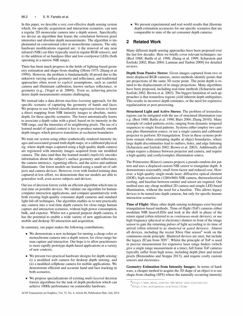
As illustrated in Figures 1, 2 and 3, our hardware setup consists ofa regular commodity camera with minor modifications. First, weremove the IR cut filter typically present, permitting sensitivity tothe spectrum range of ∼400-1100nm. Next, an IR bandpass filteroperating at 850nm (±10nm) is used to limit all other wavelengths.This makes the camera sensitive only to this specific NIR range.Finally, we add diffuse LED illumination emitting at this spectralrange. To ensure uniform lighting and limit shadowing, we build aring of six NIR LEDs around the camera, with a minimal baseline.This setup is extremely cheap compared with stereo, structured light,or ToF. It also enables a very small form-factor that could easily beembedded into a modern smartphone.
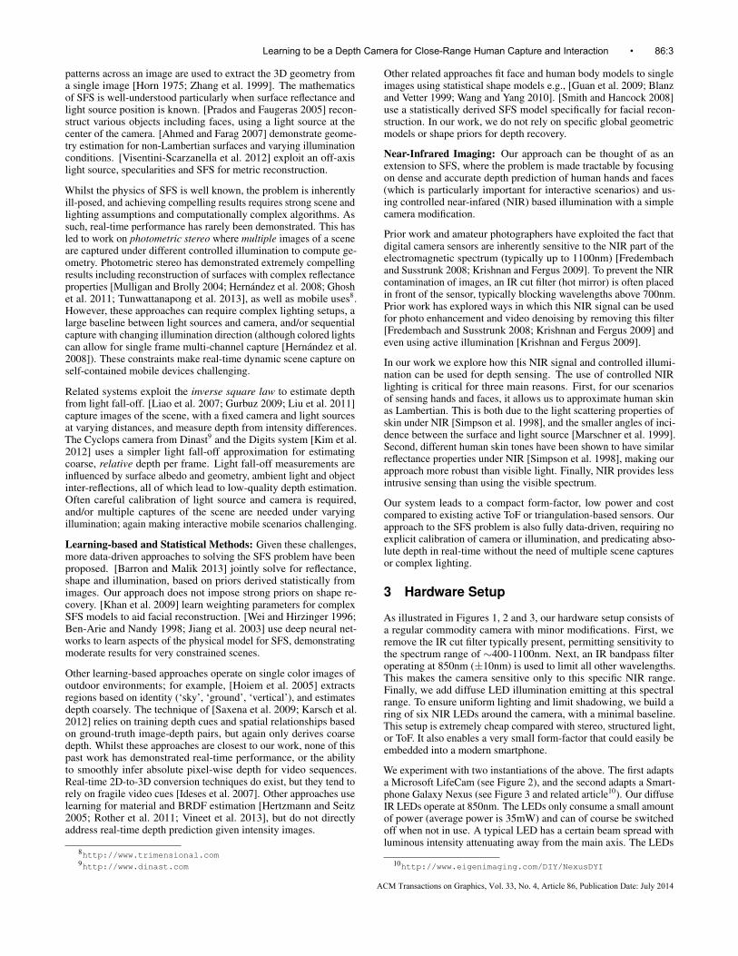
We experiment with two instantiations of the above. The first adaptsa Microsoft LifeCam (see Figure 2), and the second adapts a Smart-phone Galaxy Nexus (see Figure 3 and related article10). Our diffuseIR LEDs operate at 850nm. The LEDs only consume a small amountof power (average power is 35mW) and can of course be switchedoff when not in use. A typical LED has a certain beam spread withluminous intensity attenuating away from the main axis. The LEDs
10http://www.eigenimaging.com/DIY/NexusDYI
Learning to be a Depth Camera for Close-Range Human Capture and Interaction • 86:3
ACM Transactions on Graphics, Vol. 33, No. 4, Article 86, Publication Date: July 2014
a
d
b
cc
Figure 2: A standard Microsoft LifeCam web camera (top left) ismodified to support depth sensing (bottom row). A bandpass filteroperating at 850nm (+/-10nm) is added (a), once the front casing isopened and the IR cut filter is removed (b). A new 3D printed case(c) and ring of NIR LEDs (d) are additionally added.
Figure 3: A modified smartphone with additional NIR LED ring,bandpass filter, and custom 3D printed casing.
we use in our system have a beam angle of ±75 degree with 80%percent attenuation at the periphery. We reduce the unevenness ofillumination by using a ring of LEDs.
The camera images are downsampled by a factor of three to 640x480for our implementation (both devices support full HD capture).Downsampling can aid performance, and mitigate issues of defo-cus blur. In both our hardware implementations we measured thedefocus blur extent to be ∼2 pixels. In addition we prefilter with aGaussian filter, prior to subsampling, which substantially removesthe effect of the different gains of the Bayer pattern of RGB filters inthe IR spectrum (the signals in the visible range are blocked by theband-pass filter). Note also that chromatic aberrations are removed,because the color wavelengths are cut off by the IR bandpass filter.
4 Depth Prediction
This section details our depth prediction algorithm that learns to mapa given a pixel x in the NIR image I to an absolute depth value. Wemodel this continuous mapping y(x|I) with a multi-layered decisionforest, following the formulation described in [Keskin et al. 2012].This method attempts to simplify the problem by dividing it intosub-problems in the first layer, and then applies models trained forthese sub-problems in the second layer to solve the main problemefficiently. For the first layer we employ a classification forest, andfor the second layer we use regression forests (see [Amit and Geman1997; Breiman 2001; Criminisi and Shotton 2013]).
For our task, the problem can be significantly simplified by restrict-ing the depths of the objects to a certain range (primarily because
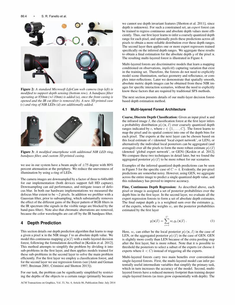
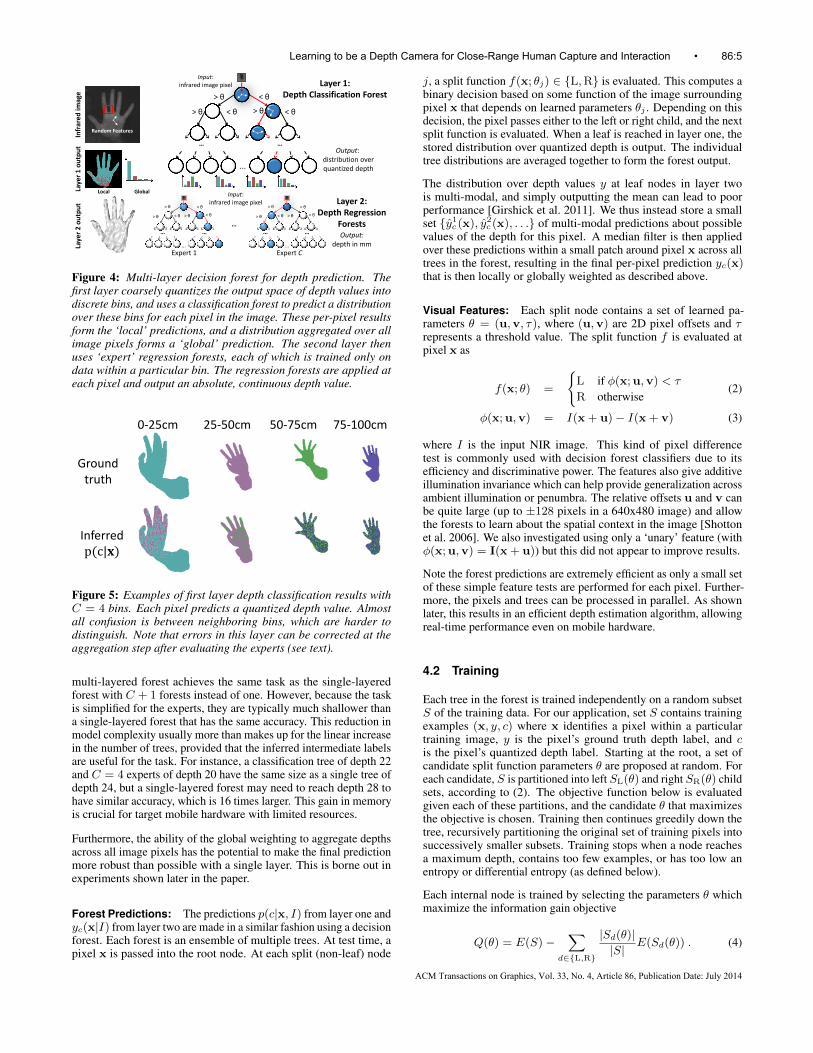
we cannot use depth invariant features [Shotton et al. 2011], sincedepth is unknown). For such a constrained set, an expert forest canbe trained to regress continuous and absolute depth values more effi-ciently. Thus, our first layer learns to infer a coarsely quantized depthrange for each pixel, and optionally pools these predictions across allpixels to obtain a more reliable distribution over these depth ranges.The second layer then applies one or more expert regressors trainedspecifically on the inferred depth ranges. We aggregate these resultsto obtain a final estimation for the absolute depth y of the pixel x.The resulting multi-layered forest is illustrated in Figure 4.
Multi-layered forests are discriminative models that learn a mappingconditioned on observations, implicitly capturing variation that existin the training set. Therefore, the forests do not need to explicitlymodel scene illumination, surface geometry and reflectance, or com-plex inter-reflections. Later we demonstrate that spatially smooth,absolute metric depth images can be obtained from these NIR im-ages for specific interaction scenarios, without the need to explicitlyknow these factors that are required by traditional SFS methods.
The next section presents details of our multi-layer decision forest-based depth estimation method.
4.1 Multi-layered Forest Architecture
Coarse, Discrete Depth Classification: Given an input pixel x andthe infrared image I , the classification forest at the first layer infersa probability distribution p(c|x, I) over coarsely quantized depthranges indicated by c, where c ∈ {1, . . . , C}. The forest learns tomap the pixel and its spatial context into one of the depth bins foreach pixel. The experts at the next layer can be chosen based onthis local estimate of c (denoted ‘local expert network’, or LEN), oralternatively the individual local posteriors can be aggregated (andaveraged) over all the pixels to form the more robust estimate p(c|I)(denoted ‘global expert network’, or GEN) [Keskin et al. 2012].We compare these two techniques in detail later, but we found theaggregated posterior p(c|I) to be more robust for our scenarios.
Examples of the inferred quantized depth predictions can be seenin Figure 5 for the specific case of C = 4. Evidently, the per-pixelpredictions are somewhat noisy. However, using GEN, we aggregateacross the entire image to predict a single quantized depth value, andthis redundancy has proved to improve accuracy.
Fine, Continuous Depth Regression: As described above, eachpixel or image is assigned a set of posterior probabilities over thedepth bins in the first layer. In the second layer, we evaluate all theexpert regression forests to form a set of absolute depth estimates.The final output depth y is a weighted sum over the estimates ycof the experts, where the weights wc are the posterior probabilitiesestimated by the first layer
y(x|I) =C∑
c=1
wcyc(x|I) . (1)
Here, wc can either be the local posterior p(c|x, I) in the case ofLEN, or the aggregated posterior p(c|I) in the case of GEN. GENis slightly more costly than LEN because of the extra pooling stepafter the first layer, but is more robust. Note that it is possible tothreshold the posteriors to select a subset of the experts (or choose kexperts where k < C) instead of triggering all the experts.
Multi-layered forests carry two main benefits over conventionalsingle-layered forests. First, the multi-layered model can infer po-tentially useful intermediate variables that simplify the primary task,which in turn increases the accuracy of the model. Second, multi-layered forests have a reduced memory footprint than training deepersingle-layered forests (as trees grow exponentially with depth). The
86:4 • S. R. Fanello et al.
ACM Transactions on Graphics, Vol. 33, No. 4, Article 86, Publication Date: July 2014
Layer 1:Depth Classification Forest
…
Layer 2:Depth Regression
Forests
Output: distribution overquantized depth
Output:depth in mm
Input:infrared image pixel
Input:infrared image pixel
Infr
are
d im
age
Laye
r 1
ou
tpu
t
Local
Random Features
Global
Laye
r 2
ou
tpu
t
Expert 1 Expert C
< θ> θ
...
< θ< θ> θ > θ
< θ> θ
...
< θ< θ> θ > θ
< θ> θ
...
< θ< θ> θ > θ
… …
… … … …
Figure 4: Multi-layer decision forest for depth prediction. Thefirst layer coarsely quantizes the output space of depth values intodiscrete bins, and uses a classification forest to predict a distributionover these bins for each pixel in the image. These per-pixel resultsform the ‘local’ predictions, and a distribution aggregated over allimage pixels forms a ‘global’ prediction. The second layer thenuses ‘expert’ regression forests, each of which is trained only ondata within a particular bin. The regression forests are applied ateach pixel and output an absolute, continuous depth value.
0-25cm 25-50cm 50-75cm 75-100cm
Groundtruth
Inferredp(c|𝐱)
Figure 5: Examples of first layer depth classification results withC = 4 bins. Each pixel predicts a quantized depth value. Almostall confusion is between neighboring bins, which are harder todistinguish. Note that errors in this layer can be corrected at theaggregation step after evaluating the experts (see text).
multi-layered forest achieves the same task as the single-layeredforest with C + 1 forests instead of one. However, because the taskis simplified for the experts, they are typically much shallower thana single-layered forest that has the same accuracy. This reduction inmodel complexity usually more than makes up for the linear increasein the number of trees, provided that the inferred intermediate labelsare useful for the task. For instance, a classification tree of depth 22and C = 4 experts of depth 20 have the same size as a single tree ofdepth 24, but a single-layered forest may need to reach depth 28 tohave similar accuracy, which is 16 times larger. This gain in memoryis crucial for target mobile hardware with limited resources.
Furthermore, the ability of the global weighting to aggregate depthsacross all image pixels has the potential to make the final predictionmore robust than possible with a single layer. This is borne out inexperiments shown later in the paper.
Forest Predictions: The predictions p(c|x, I) from layer one andyc(x|I) from layer two are made in a similar fashion using a decisionforest. Each forest is an ensemble of multiple trees. At test time, apixel x is passed into the root node. At each split (non-leaf) node
j, a split function f(x; θj) ∈ {L,R} is evaluated. This computes abinary decision based on some function of the image surroundingpixel x that depends on learned parameters θj . Depending on thisdecision, the pixel passes either to the left or right child, and the nextsplit function is evaluated. When a leaf is reached in layer one, thestored distribution over quantized depth is output. The individualtree distributions are averaged together to form the forest output.
The distribution over depth values y at leaf nodes in layer twois multi-modal, and simply outputting the mean can lead to poorperformance [Girshick et al. 2011]. We thus instead store a smallset {y1c (x), y2c (x), . . .} of multi-modal predictions about possiblevalues of the depth for this pixel. A median filter is then appliedover these predictions within a small patch around pixel x across alltrees in the forest, resulting in the final per-pixel prediction yc(x)that is then locally or globally weighted as described above.
Visual Features: Each split node contains a set of learned pa-rameters θ = (u,v, τ), where (u,v) are 2D pixel offsets and τrepresents a threshold value. The split function f is evaluated atpixel x as
f(x; θ) =
{L if φ(x;u,v) < τ
R otherwise(2)
φ(x;u,v) = I(x+ u)− I(x+ v) (3)
where I is the input NIR image. This kind of pixel differencetest is commonly used with decision forest classifiers due to itsefficiency and discriminative power. The features also give additiveillumination invariance which can help provide generalization acrossambient illumination or penumbra. The relative offsets u and v canbe quite large (up to ±128 pixels in a 640x480 image) and allowthe forests to learn about the spatial context in the image [Shottonet al. 2006]. We also investigated using only a ‘unary’ feature (withφ(x;u,v) = I(x+ u)) but this did not appear to improve results.
Note the forest predictions are extremely efficient as only a small setof these simple feature tests are performed for each pixel. Further-more, the pixels and trees can be processed in parallel. As shownlater, this results in an efficient depth estimation algorithm, allowingreal-time performance even on mobile hardware.
4.2 Training
Each tree in the forest is trained independently on a random subsetS of the training data. For our application, set S contains trainingexamples (x, y, c) where x identifies a pixel within a particulartraining image, y is the pixel’s ground truth depth label, and cis the pixel’s quantized depth label. Starting at the root, a set ofcandidate split function parameters θ are proposed at random. Foreach candidate, S is partitioned into left SL(θ) and right SR(θ) childsets, according to (2). The objective function below is evaluatedgiven each of these partitions, and the candidate θ that maximizesthe objective is chosen. Training then continues greedily down thetree, recursively partitioning the original set of training pixels intosuccessively smaller subsets. Training stops when a node reachesa maximum depth, contains too few examples, or has too low anentropy or differential entropy (as defined below).
Each internal node is trained by selecting the parameters θ whichmaximize the information gain objective
Q(θ) = E(S)−∑
d∈{L,R}
|Sd(θ)||S| E(Sd(θ)) . (4)
Learning to be a Depth Camera for Close-Range Human Capture and Interaction • 86:5
ACM Transactions on Graphics, Vol. 33, No. 4, Article 86, Publication Date: July 2014
ba
real capture synthetic generation
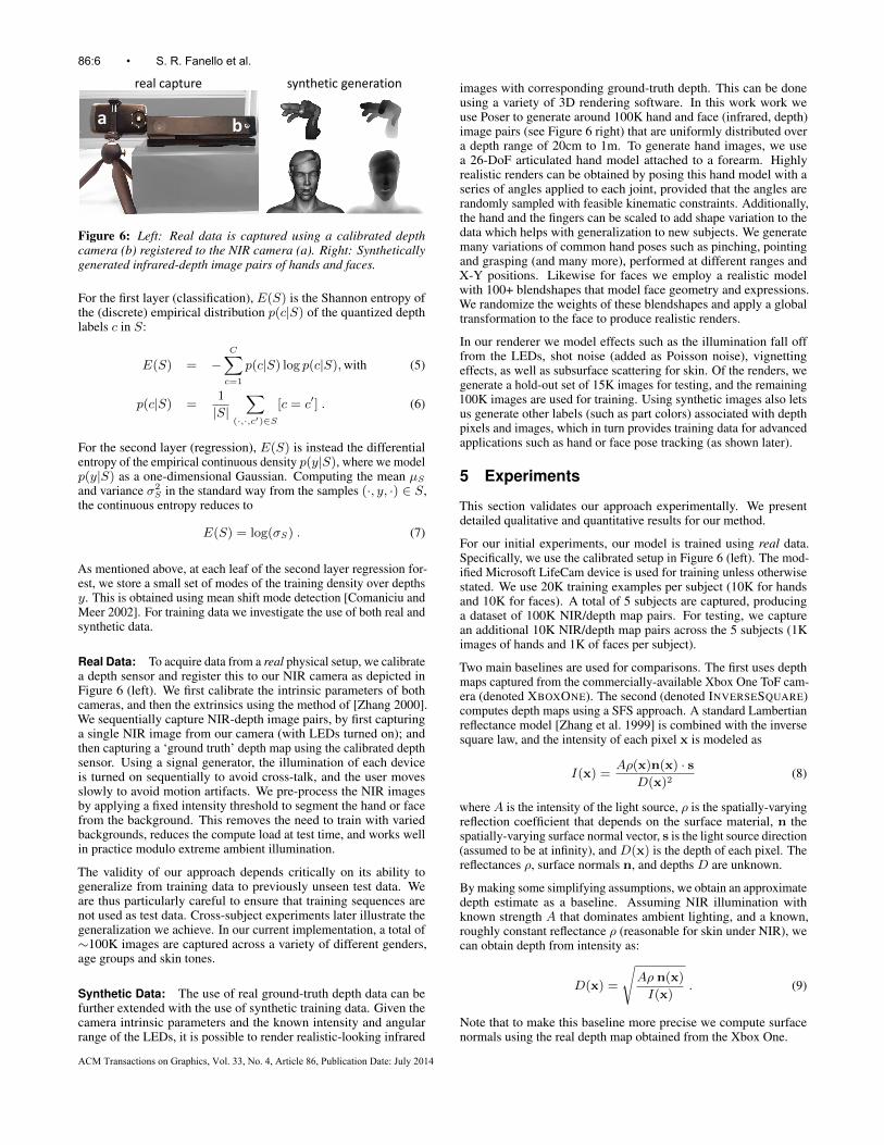
Figure 6: Left: Real data is captured using a calibrated depthcamera (b) registered to the NIR camera (a). Right: Syntheticallygenerated infrared-depth image pairs of hands and faces.
For the first layer (classification), E(S) is the Shannon entropy ofthe (discrete) empirical distribution p(c|S) of the quantized depthlabels c in S:
E(S) = −C∑
c=1
p(c|S) log p(c|S),with (5)
p(c|S) =1
|S|∑
(·,·,c′)∈S
[c = c′] . (6)
For the second layer (regression), E(S) is instead the differentialentropy of the empirical continuous density p(y|S), where we modelp(y|S) as a one-dimensional Gaussian. Computing the mean µS
and variance σ2S in the standard way from the samples (·, y, ·) ∈ S,
the continuous entropy reduces to
E(S) = log(σS) . (7)
As mentioned above, at each leaf of the second layer regression for-est, we store a small set of modes of the training density over depthsy. This is obtained using mean shift mode detection [Comaniciu andMeer 2002]. For training data we investigate the use of both real andsynthetic data.
Real Data: To acquire data from a real physical setup, we calibratea depth sensor and register this to our NIR camera as depicted inFigure 6 (left). We first calibrate the intrinsic parameters of bothcameras, and then the extrinsics using the method of [Zhang 2000].We sequentially capture NIR-depth image pairs, by first capturinga single NIR image from our camera (with LEDs turned on); andthen capturing a ‘ground truth’ depth map using the calibrated depthsensor. Using a signal generator, the illumination of each deviceis turned on sequentially to avoid cross-talk, and the user movesslowly to avoid motion artifacts. We pre-process the NIR imagesby applying a fixed intensity threshold to segment the hand or facefrom the background. This removes the need to train with variedbackgrounds, reduces the compute load at test time, and works wellin practice modulo extreme ambient illumination.
The validity of our approach depends critically on its ability togeneralize from training data to previously unseen test data. Weare thus particularly careful to ensure that training sequences arenot used as test data. Cross-subject experiments later illustrate thegeneralization we achieve. In our current implementation, a total of∼100K images are captured across a variety of different genders,age groups and skin tones.
Synthetic Data: The use of real ground-truth depth data can befurther extended with the use of synthetic training data. Given thecamera intrinsic parameters and the known intensity and angularrange of the LEDs, it is possible to render realistic-looking infrared
images with corresponding ground-truth depth. This can be doneusing a variety of 3D rendering software. In this work work weuse Poser to generate around 100K hand and face (infrared, depth)image pairs (see Figure 6 right) that are uniformly distributed overa depth range of 20cm to 1m. To generate hand images, we usea 26-DoF articulated hand model attached to a forearm. Highlyrealistic renders can be obtained by posing this hand model with aseries of angles applied to each joint, provided that the angles arerandomly sampled with feasible kinematic constraints. Additionally,the hand and the fingers can be scaled to add shape variation to thedata which helps with generalization to new subjects. We generatemany variations of common hand poses such as pinching, pointingand grasping (and many more), performed at different ranges andX-Y positions. Likewise for faces we employ a realistic modelwith 100+ blendshapes that model face geometry and expressions.We randomize the weights of these blendshapes and apply a globaltransformation to the face to produce realistic renders.
In our renderer we model effects such as the illumination fall offfrom the LEDs, shot noise (added as Poisson noise), vignettingeffects, as well as subsurface scattering for skin. Of the renders, wegenerate a hold-out set of 15K images for testing, and the remaining100K images are used for training. Using synthetic images also letsus generate other labels (such as part colors) associated with depthpixels and images, which in turn provides training data for advancedapplications such as hand or face pose tracking (as shown later).
5 Experiments
This section validates our approach experimentally. We presentdetailed qualitative and quantitative results for our method.
For our initial experiments, our model is trained using real data.Specifically, we use the calibrated setup in Figure 6 (left). The mod-ified Microsoft LifeCam device is used for training unless otherwisestated. We use 20K training examples per subject (10K for handsand 10K for faces). A total of 5 subjects are captured, producinga dataset of 100K NIR/depth map pairs. For testing, we capturean additional 10K NIR/depth map pairs across the 5 subjects (1Kimages of hands and 1K of faces per subject).
Two main baselines are used for comparisons. The first uses depthmaps captured from the commercially-available Xbox One ToF cam-era (denoted XBOXONE). The second (denoted INVERSESQUARE)computes depth maps using a SFS approach. A standard Lambertianreflectance model [Zhang et al. 1999] is combined with the inversesquare law, and the intensity of each pixel x is modeled as
I(x) =Aρ(x)n(x) · s
D(x)2(8)
where A is the intensity of the light source, ρ is the spatially-varyingreflection coefficient that depends on the surface material, n thespatially-varying surface normal vector, s is the light source direction(assumed to be at infinity), and D(x) is the depth of each pixel. Thereflectances ρ, surface normals n, and depths D are unknown.
By making some simplifying assumptions, we obtain an approximatedepth estimate as a baseline. Assuming NIR illumination withknown strength A that dominates ambient lighting, and a known,roughly constant reflectance ρ (reasonable for skin under NIR), wecan obtain depth from intensity as:
D(x) =
√Aρ n(x)
I(x). (9)
Note that to make this baseline more precise we compute surfacenormals using the real depth map obtained from the Xbox One.
86:6 • S. R. Fanello et al.
ACM Transactions on Graphics, Vol. 33, No. 4, Article 86, Publication Date: July 2014
> 0.02m
0.0m
Input IR Predicted Depth Xbox One ToFInverse Square Error: Predicted Depth ↔ Xbox ToF
Hand Part Classification
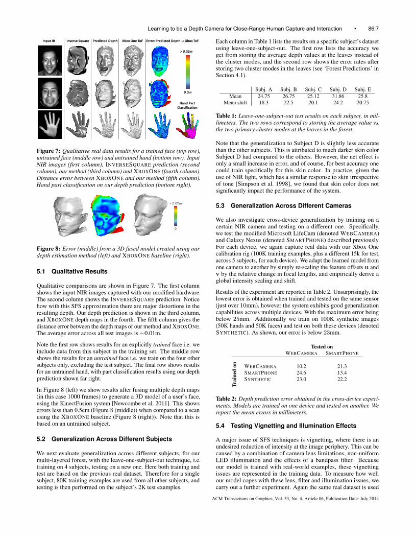
Figure 7: Qualitative real data results for a trained face (top row),untrained face (middle row) and untrained hand (bottom row). InputNIR images (first column), INVERSESQUARE prediction (secondcolumn), our method (third column) and XBOXONE (fourth column).Distance error between XBOXONE and our method (fifth column).Hand part classification on our depth prediction (bottom right).
Figure 8: Error (middle) from a 3D fused model created using ourdepth estimation method (left) and XBOXONE baseline (right).
5.1 Qualitative Results
Qualitative comparisons are shown in Figure 7. The first columnshows the input NIR images captured with our modified hardware.The second column shows the INVERSESQUARE prediction. Noticehow with this SFS approximation there are major distortions in theresulting depth. Our depth prediction is shown in the third column,and XBOXONE depth maps in the fourth. The fifth column gives thedistance error between the depth maps of our method and XBOXONE.The average error across all test images is ∼0.01m.
Note the first row shows results for an explicitly trained face i.e. weinclude data from this subject in the training set. The middle rowshows the results for an untrained face i.e. we train on the four othersubjects only, excluding the test subject. The final row shows resultsfor an untrained hand, with part classification results using our depthprediction shown far right.
In Figure 8 (left) we show results after fusing multiple depth maps(in this case 1000 frames) to generate a 3D model of a user’s face,using the KinectFusion system [Newcombe et al. 2011]. This showserrors less than 0.5cm (Figure 8 (middle)) when compared to a scanusing the XBOXONE baseline (Figure 8 (right)). Note that this isbased on an untrained subject.
5.2 Generalization Across Different Subjects
We next evaluate generalization across different subjects, for ourmulti-layered forest, with the leave-one-subject-out technique, i.e.training on 4 subjects, testing on a new one. Here both training andtest are based on the previous real dataset. Therefore for a singlesubject, 80K training examples are used from all other subjects, andtesting is then performed on the subject’s 2K test examples.
Each column in Table 1 lists the results on a specific subject’s datasetusing leave-one-subject-out. The first row lists the accuracy weget from storing the average depth values at the leaves instead ofthe cluster modes, and the second row shows the error rates afterstoring two cluster modes in the leaves (see ‘Forest Predictions’ inSection 4.1).
Subj. A Subj. B Subj. C Subj. D Subj. EMean 24.75 26.75 25.12 31.86 25.8
Mean shift 18.3 22.5 20.1 24.2 20.75
Table 1: Leave-one-subject-out test results on each subject, in mil-limeters. The two rows correspond to storing the average value vs.the two primary cluster modes at the leaves in the forest.
Note that the generalization to Subject D is slightly less accuratethan the other subjects. This is attributed to much darker skin colorSubject D had compared to the others. However, the net effect isonly a small increase in error, and of course, for best accuracy onecould train specifically for this skin color. In practice, given theuse of NIR light, which has a similar response to skin irrespectiveof tone [Simpson et al. 1998], we found that skin color does notsignificantly impact the performance of the system.
5.3 Generalization Across Different Cameras
We also investigate cross-device generalization by training on acertain NIR camera and testing on a different one. Specifically,we test the modified Microsoft LifeCam (denoted WEBCAMERA)and Galaxy Nexus (denoted SMARTPHONE) described previously.For each device, we again capture real data with our Xbox Onecalibration rig (100K training examples, plus a different 15k for test,across 5 subjects, for each device). We adapt the learned model fromone camera to another by simply re-scaling the feature offsets u andv by the relative change in focal lengths, and empirically derive aglobal intensity scaling and shift.
Results of the experiment are reported in Table 2. Unsurprisingly, thelowest error is obtained when trained and tested on the same sensor(just over 10mm), however the system exhibits good generalizationcapabilities across multiple devices. With the maximum error beingbelow 25mm. Additionally we train on 100K synthetic images(50K hands and 50K faces) and test on both these devices (denotedSYNTHETIC). As shown, our error is below 23mm.
Tested onWEBCAMERA SMARTPHONE
WEBCAMERA 10.2 21.3SMARTPHONE 24.6 13.4SYNTHETIC 23.0 22.2
Trai
ned
on
Table 2: Depth prediction error obtained in the cross-device experi-ments. Models are trained on one device and tested on another. Wereport the mean errors in millimeters.
5.4 Testing Vignetting and Illumination Effects
A major issue of SFS techniques is vignetting, where there is anundesired reduction of intensity at the image periphery. This can becaused by a combination of camera lens limitations, non-uniformLED illumination and the effects of a bandpass filter. Becauseour model is trained with real-world examples, these vignettingissues are represented in the training data. To measure how wellour model copes with these lens, filter and illumination issues, wecarry out a further experiment. Again the same real dataset is used
Learning to be a Depth Camera for Close-Range Human Capture and Interaction • 86:7
ACM Transactions on Graphics, Vol. 33, No. 4, Article 86, Publication Date: July 2014
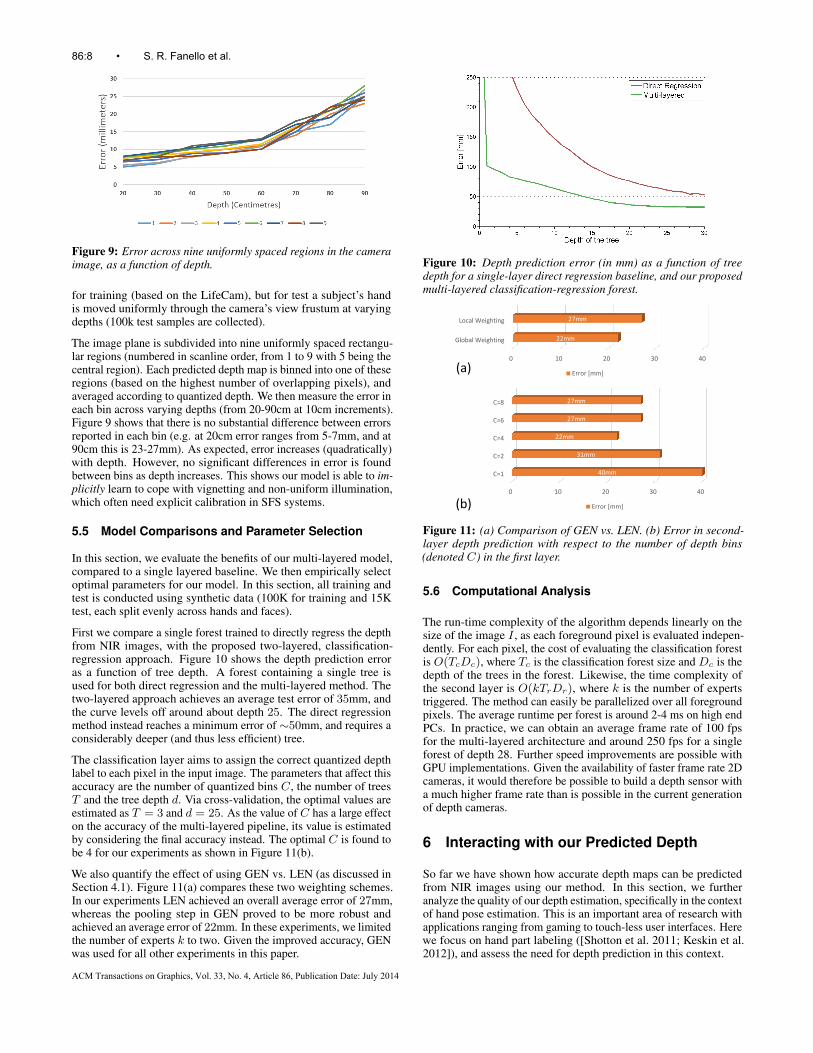
Figure 9: Error across nine uniformly spaced regions in the cameraimage, as a function of depth.
for training (based on the LifeCam), but for test a subject’s handis moved uniformly through the camera’s view frustum at varyingdepths (100k test samples are collected).
The image plane is subdivided into nine uniformly spaced rectangu-lar regions (numbered in scanline order, from 1 to 9 with 5 being thecentral region). Each predicted depth map is binned into one of theseregions (based on the highest number of overlapping pixels), andaveraged according to quantized depth. We then measure the error ineach bin across varying depths (from 20-90cm at 10cm increments).Figure 9 shows that there is no substantial difference between errorsreported in each bin (e.g. at 20cm error ranges from 5-7mm, and at90cm this is 23-27mm). As expected, error increases (quadratically)with depth. However, no significant differences in error is foundbetween bins as depth increases. This shows our model is able to im-plicitly learn to cope with vignetting and non-uniform illumination,which often need explicit calibration in SFS systems.
5.5 Model Comparisons and Parameter Selection
In this section, we evaluate the benefits of our multi-layered model,compared to a single layered baseline. We then empirically selectoptimal parameters for our model. In this section, all training andtest is conducted using synthetic data (100K for training and 15Ktest, each split evenly across hands and faces).
First we compare a single forest trained to directly regress the depthfrom NIR images, with the proposed two-layered, classification-regression approach. Figure 10 shows the depth prediction erroras a function of tree depth. A forest containing a single tree isused for both direct regression and the multi-layered method. Thetwo-layered approach achieves an average test error of 35mm, andthe curve levels off around about depth 25. The direct regressionmethod instead reaches a minimum error of ∼50mm, and requires aconsiderably deeper (and thus less efficient) tree.
The classification layer aims to assign the correct quantized depthlabel to each pixel in the input image. The parameters that affect thisaccuracy are the number of quantized bins C, the number of treesT and the tree depth d. Via cross-validation, the optimal values areestimated as T = 3 and d = 25. As the value of C has a large effecton the accuracy of the multi-layered pipeline, its value is estimatedby considering the final accuracy instead. The optimal C is found tobe 4 for our experiments as shown in Figure 11(b).
We also quantify the effect of using GEN vs. LEN (as discussed inSection 4.1). Figure 11(a) compares these two weighting schemes.In our experiments LEN achieved an overall average error of 27mm,whereas the pooling step in GEN proved to be more robust andachieved an average error of 22mm. In these experiments, we limitedthe number of experts k to two. Given the improved accuracy, GENwas used for all other experiments in this paper.
Figure 10: Depth prediction error (in mm) as a function of treedepth for a single-layer direct regression baseline, and our proposedmulti-layered classification-regression forest.
0 10 20 30 40
Global Weighting
Local Weighting
22mm
27mm
Error [mm]
0 10 20 30 40
C=1
C=2
C=4
C=6
C=8
40mm
31mm
22mm
27mm
27mm
Error [mm]
(a)
(b)
Figure 11: (a) Comparison of GEN vs. LEN. (b) Error in second-layer depth prediction with respect to the number of depth bins(denoted C) in the first layer.
5.6 Computational Analysis
The run-time complexity of the algorithm depends linearly on thesize of the image I , as each foreground pixel is evaluated indepen-dently. For each pixel, the cost of evaluating the classification forestis O(TcDc), where Tc is the classification forest size and Dc is thedepth of the trees in the forest. Likewise, the time complexity ofthe second layer is O(kTrDr), where k is the number of expertstriggered. The method can easily be parallelized over all foregroundpixels. The average runtime per forest is around 2-4 ms on high endPCs. In practice, we can obtain an average frame rate of 100 fpsfor the multi-layered architecture and around 250 fps for a singleforest of depth 28. Further speed improvements are possible withGPU implementations. Given the availability of faster frame rate 2Dcameras, it would therefore be possible to build a depth sensor witha much higher frame rate than is possible in the current generationof depth cameras.
6 Interacting with our Predicted Depth
So far we have shown how accurate depth maps can be predictedfrom NIR images using our method. In this section, we furtheranalyze the quality of our depth estimation, specifically in the contextof hand pose estimation. This is an important area of research withapplications ranging from gaming to touch-less user interfaces. Herewe focus on hand part labeling ([Shotton et al. 2011; Keskin et al.2012]), and assess the need for depth prediction in this context.
86:8 • S. R. Fanello et al.
ACM Transactions on Graphics, Vol. 33, No. 4, Article 86, Publication Date: July 2014
From Theory to Application: Hand Part Classification
We answer the following question:Given different sensors/modalities/inputs, which is the best one for hand part labelling/gesture recognition?
Depth Infrared Hand Part Classification
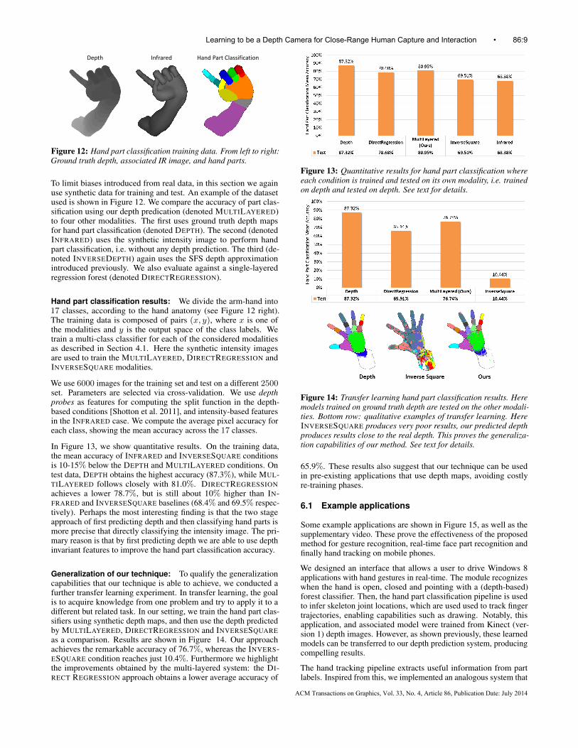
Figure 12: Hand part classification training data. From left to right:Ground truth depth, associated IR image, and hand parts.
To limit biases introduced from real data, in this section we againuse synthetic data for training and test. An example of the datasetused is shown in Figure 12. We compare the accuracy of part clas-sification using our depth predication (denoted MULTILAYERED)to four other modalities. The first uses ground truth depth mapsfor hand part classification (denoted DEPTH). The second (denotedINFRARED) uses the synthetic intensity image to perform handpart classification, i.e. without any depth prediction. The third (de-noted INVERSEDEPTH) again uses the SFS depth approximationintroduced previously. We also evaluate against a single-layeredregression forest (denoted DIRECTREGRESSION).
Hand part classification results: We divide the arm-hand into17 classes, according to the hand anatomy (see Figure 12 right).The training data is composed of pairs (x, y), where x is one ofthe modalities and y is the output space of the class labels. Wetrain a multi-class classifier for each of the considered modalitiesas described in Section 4.1. Here the synthetic intensity imagesare used to train the MULTILAYERED, DIRECTREGRESSION andINVERSESQUARE modalities.
We use 6000 images for the training set and test on a different 2500set. Parameters are selected via cross-validation. We use depthprobes as features for computing the split function in the depth-based conditions [Shotton et al. 2011], and intensity-based featuresin the INFRARED case. We compute the average pixel accuracy foreach class, showing the mean accuracy across the 17 classes.
In Figure 13, we show quantitative results. On the training data,the mean accuracy of INFRARED and INVERSESQUARE conditionsis 10-15% below the DEPTH and MULTILAYERED conditions. Ontest data, DEPTH obtains the highest accuracy (87.3%), while MUL-TILAYERED follows closely with 81.0%. DIRECTREGRESSIONachieves a lower 78.7%, but is still about 10% higher than IN-FRARED and INVERSESQUARE baselines (68.4% and 69.5% respec-tively). Perhaps the most interesting finding is that the two stageapproach of first predicting depth and then classifying hand parts ismore precise that directly classifying the intensity image. The pri-mary reason is that by first predicting depth we are able to use depthinvariant features to improve the hand part classification accuracy.
Generalization of our technique: To qualify the generalizationcapabilities that our technique is able to achieve, we conducted afurther transfer learning experiment. In transfer learning, the goalis to acquire knowledge from one problem and try to apply it to adifferent but related task. In our setting, we train the hand part clas-sifiers using synthetic depth maps, and then use the depth predictedby MULTILAYERED, DIRECTREGRESSION and INVERSESQUAREas a comparison. Results are shown in Figure 14. Our approachachieves the remarkable accuracy of 76.7%, whereas the INVERS-ESQUARE condition reaches just 10.4%. Furthermore we highlightthe improvements obtained by the multi-layered system: the DI-RECT REGRESSION approach obtains a lower average accuracy of
Figure 13: Quantitative results for hand part classification whereeach condition is trained and tested on its own modality, i.e. trainedon depth and tested on depth. See text for details.
Figure 14: Transfer learning hand part classification results. Heremodels trained on ground truth depth are tested on the other modali-ties. Bottom row: qualitative examples of transfer learning. HereINVERSESQUARE produces very poor results, our predicted depthproduces results close to the real depth. This proves the generaliza-tion capabilities of our method. See text for details.
65.9%. These results also suggest that our technique can be usedin pre-existing applications that use depth maps, avoiding costlyre-training phases.
6.1 Example applications
Some example applications are shown in Figure 15, as well as thesupplementary video. These prove the effectiveness of the proposedmethod for gesture recognition, real-time face part recognition andfinally hand tracking on mobile phones.
We designed an interface that allows a user to drive Windows 8applications with hand gestures in real-time. The module recognizeswhen the hand is open, closed and pointing with a (depth-based)forest classifier. Then, the hand part classification pipeline is usedto infer skeleton joint locations, which are used used to track fingertrajectories, enabling capabilities such as drawing. Notably, thisapplication, and associated model were trained from Kinect (ver-sion 1) depth images. However, as shown previously, these learnedmodels can be transferred to our depth prediction system, producingcompelling results.
The hand tracking pipeline extracts useful information from partlabels. Inspired from this, we implemented an analogous system that
Learning to be a Depth Camera for Close-Range Human Capture and Interaction • 86:9
ACM Transactions on Graphics, Vol. 33, No. 4, Article 86, Publication Date: July 2014
Figure 15: Some example applications created using our method.
estimates part labels for the face, which are then used to track certainlandmarks and expressions. Here, we train a facial part classifier andan expression regressor on synthetic face images, and then replacethe depth data with our method at test-time. See Figures 1 and 15and the supplementary video for examples.
Finally, to demonstrate the capabilities of our method, as well asthe simplicity and applicability of the hardware customization step,we designed a mobile phone application that first predicts depth,then performs hand part classification, followed by simple modelfitting. This allows fully articulated hand tracking on the mobilephone, in a form-factor that is prohibitive for current generationsof depth cameras. Examples are given in Figures 1 and 15 and thesupplementary video.
6.2 Limitations
Whilst we have demonstrated the utility of our approach, there areclearly limitations. Firstly we train for uniform surface albedo (inthis case skin) which limits our depth estimation to human facesor hands, or any other specific object. Our system fails to predictdepth for surfaces with varying reflectance properties. Another issueof our approach is the sensitivity to ambient IR (a problem withother depth camera techniques as well). The narrow bandpass filterhelps alleviates some of these issues. A further possibility here is tosubtract ambient illumination, by turning the illuminant on and offat alternate frames, and subtracting background ambient IR. This ex-tension would require lower-level access to the sync signal from thecamera, and can suffer from motion artifacts, although with a high-enough frame rate this can be alleviated. Alternatively, it may bepossible to include sufficiently large ambient illumination variationsin the training data (especially when using synthetic data) that thesystem learns some level of invariance to ambient IR illumination.
Other camera specific effects such as vignetting can also be an issue,particularly when training our system for general cross device usage.Note however when training on real data on a single device, ourproposed model implicitly learns to account for vignetting effectswithout the need to explicitly formulate them. The forest learns amapping conditioned on these vignetting effects. Given sufficienttraining data, we found the system to be remarkably insensitive toabsolute spatial location in the view frustum. However, this type ofper-device training can be costly or impractical in certain scenarios.
Another limitation is that the camera modification limits the abilityto capture visible light images. One approach to enable both visibleand IR imaging is to replace the standard RGB Bayer pattern withan RGBI pattern. Camera manufacturers such as OmniVision andAptina now produce such cameras. This would still be significantlylower cost and power than a full depth camera, though would requirethe use of a custom sensor.
7 Conclusion
In this paper, we proposed and demonstrated a low-cost technique toturn any 2D camera into a real-time depth sensor with only simpleand cheap modifications. Diffuse NIR LEDs illuminate objectsnear the camera, and capture the reflected light with the help ofan added band pass filter. The actual depth calculation is done bya machine learning algorithm, and can learn to map a pixel and
its context to an absolute, metric depth value. As this is a datadriven, discriminative machine learning method, it learns to captureany variation that exists in the dataset, such as changes in shape,geometry, skin color, ambient illumination, complex inter-objectreflections and even vignetting effects, without the need to explicitlyformulate them. To capture this much information via simple rulesencoded in the decision forests, we employed a multi-layered forestthat simplifies this problem in the first layer by predicting coarsequantized depth ranges for the object.
We demonstrated the efficiency of this method through qualitativeand quantitative experiments. In particular we showed comparisonswith other modalities for a range of applications, cross-subject andcross-device generalization capabilities, as well as the high qualityinferred depth for hand and face tracking, and 3D reconstruction. Itshould be noted that the method described is not for a general pur-pose depth camera. Whilst this method cannot replace commoditydepth sensors for general use, our hope is that it will enable 3D faceand hand sensing and interactive systems in novel contexts.
References
AHMED, A. H., AND FARAG, A. A. 2007. Shape from shadingunder various imaging conditions. In Proc. CVPR, IEEE, 1–8.
AMIT, Y., AND GEMAN, D. 1997. Shape quantization and recogni-tion with randomized trees. Neural Computation 9, 7.
BARRON, J. T., AND MALIK, J. 2013. Shape, illumination, and re-flectance from shading. Tech. Rep. UCB/EECS-2013-117, EECS,UC Berkeley, May.
BATLLE, J., MOUADDIB, E., AND SALVI, J. 1998. Recent progressin coded structured light as a technique to solve the correspon-dence problem: a survey. Pattern Recognition 31, 7, 963–982.
BEN-ARIE, J., AND NANDY, D. 1998. A neural network approachfor reconstructing surface shape from shading. In In Proc. ICIP98., vol. 2, IEEE, 972–976.
BESL, P. J. 1988. Active, optical range imaging sensors. Machinevision and applications 1, 2, 127–152.
BLAIS, F. 2004. Review of 20 years of range sensor development.Journal of Electronic Imaging 13, 1.
BLANZ, V., AND VETTER, T. 1999. A morphable model for thesynthesis of 3D faces. Proc. ACM SIGGRAPH.
BREIMAN, L. 2001. Random forests. Machine Learning 45, 1.
BROWN, M. Z., BURSCHKA, D., AND HAGER, G. D. 2003.Advances in computational stereo. PAMI 25, 8, 993–1008.
COMANICIU, D., AND MEER, P. 2002. Mean shift: A robustapproach toward feature space analysis. IEEE Trans. PAMI 24, 5.
CRIMINISI, A., AND SHOTTON, J. 2013. Decision Forests forComputer Vision and Medical Image Analysis. Springer.
FREDEMBACH, C., AND SUSSTRUNK, S. 2008. Colouring the near-infrared. In Color and Imaging Conference, vol. 2008, Societyfor Imaging Science and Technology, 176–182.
GHOSH, A., FYFFE, G., TUNWATTANAPONG, B., BUSCH, J., YU,X., AND DEBEVEC, P. 2011. Multiview face capture usingpolarized spherical gradient illumination. ACM Transactions onGraphics (TOG) 30, 6, 129.
GIRSHICK, R., SHOTTON, J., KOHLI, P., CRIMINISI, A., ANDFITZGIBBON, A. 2011. Efficient regression of general-activityhuman poses from depth images. In Proc. ICCV.
86:10 • S. R. Fanello et al.
ACM Transactions on Graphics, Vol. 33, No. 4, Article 86, Publication Date: July 2014
GUAN, P., WEISS, A., BALAN, A., AND BLACK, M. 2009. Es-timating human shape and pose from a single image. In Proc.ICCV.
GURBUZ, S. 2009. Application of inverse square law for 3d sensing.In SPIE Optical Engineering+ Applications, International Societyfor Optics and Photonics, 744706–744706.
HERNANDEZ, C., VOGIATZIS, G., AND CIPOLLA, R. 2008. Mul-tiview photometric stereo. IEEE Trans. PAMI 30, 3, 548–554.
HERTZMANN, A., AND SEITZ, S. 2005. Example-based photomet-ric stereo: Shape reconstruction with general, varying BRDFs.PAMI 27, 8.
HOIEM, D., EFROS, A., AND HEBERT, M. 2005. Automatic photopop-up. In Proc. ACM SIGGRAPH.
HORN, B. K. 1975. Obtaining shape from shading information.The psychology of computer vision, 115–155.
IDESES, I., YAROSLAVSKY, L., AND FISHBAIN, B. 2007. Real-time 2D to 3D video conversion. J. of Real-Time Image Process-ing 2, 3–9.
JIANG, T., LIU, B., LU, Y., AND EVANS, D. 2003. A neuralnetwork approach to shape from shading. International journalof computer mathematics 80, 4, 433–439.
KARSCH, K., LIU, C., AND KANG, S. 2012. Depth extractionfrom video using non-parametric sampling. In Proc. ECCV.
KESKIN, C., KIRAC, F., KARA, Y., AND AKARUN, L. 2012. Handpose estimation and hand shape classification using multi-layeredrandomized decision forests. In Proc. ECCV.
KHAN, N., TRAN, L., AND TAPPEN, M. 2009. Training many-parameter shape-from-shading models using a surface database.In Proc. ICCV Workshop.
KIM, D., HILLIGES, O., IZADI, S., BUTLER, A. D., CHEN, J.,OIKONOMIDIS, I., AND OLIVIER, P. 2012. Digits: freehand3d interactions anywhere using a wrist-worn gloveless sensor.In Proceedings of the 25th annual ACM symposium on Userinterface software and technology, ACM, 167–176.
KRISHNAN, D., AND FERGUS, R. 2009. Dark flash photography.In ACM Transactions on Graphics, SIGGRAPH 2009 ConferenceProceedings, vol. 28.
LANMAN, D., AND TAUBIN, G. 2009. Build your own 3D scan-ner: 3D photography for beginners. In ACM SIGGRAPH 2009Courses, ACM, 8.
LIAO, M., WANG, L., YANG, R., AND GONG, M. 2007. Lightfall-off stereo. In Proc. CVPR.
LIU, C. P., CHENG, B. H., CHEN, P. L., AND JENG, T. R. 2011.Study of three-dimensional sensing by using inverse square law.Magnetics, IEEE Transactions on 47, 3, 687–690.
MARSCHNER, S. R., WESTIN, S. H., LAFORTUNE, E. P., TOR-RANCE, K. E., AND GREENBERG, D. P. 1999. Image-basedBRDF measurement including human skin. In Rendering Tech-niques 99. Springer, 131–144.
MULLIGAN, J., AND BROLLY, X. 2004. Surface determination byphotometric ranging. In Proc. CVPR Workshop.
NEWCOMBE, R. A., IZADI, S., ET AL. 2011. Kinectfusion: Real-time dense surface mapping and tracking. In Mixed and aug-mented reality (ISMAR), 2011 10th IEEE international sympo-sium on, IEEE, 127–136.
PRADOS, E., AND FAUGERAS, O. 2005. Shape from shading: awell-posed problem? In Proc. CVPR, vol. 2.
REMONDINO, F., AND STOPPA, D. 2013. ToF range-imagingcameras. Springer.
ROTHER, C., KIEFEL, M., ZHANG, L., SCHOLKOPF, B., ANDGEHLER, P. V. 2011. Recovering intrinsic images with a globalsparsity prior on reflectance. In Proc. NIPS.
SAXENA, A., SUN, M., AND NG, A. 2009. Make3D: Learning 3Dscene structure from a single still image. PAMI 31, 5, 824–840.
SCHARSTEIN, D., AND SZELISKI, R. 2002. A taxonomy andevaluation of dense two-frame stereo correspondence algorithms.In IJCV.
SHOTTON, J., WINN, J., ROTHER, C., AND CRIMINISI, A. 2006.TextonBoost: Joint appearance, shape and context modeling formulti-class object recognition and segmentation. In Proc. ECCV.
SHOTTON, J., FITZGIBBON, A., COOK, M., SHARP, T., FINOC-CHIO, M., MOORE, R., KIPMAN, A., AND BLAKE, A. 2011.Real-time human pose recognition in parts from single depthimages. In Proc. CVPR.
SIMPSON, C. R., KOHL, M., ESSENPREIS, M., AND COPE, M.1998. Near-infrared optical properties of ex vivo human skin andsubcutaneous tissues measured using the monte carlo inversiontechnique. Physics in Medicine and Biology 43, 2465–2478.
SMITH, W. A., AND HANCOCK, E. R. 2008. Facial shape-from-shading and recognition using principal geodesic analysis androbust statistics. International Journal of Computer Vision 76, 1,71–91.
TUNWATTANAPONG, B., FYFFE, G., GRAHAM, P., BUSCH, J.,YU, X., GHOSH, A., AND DEBEVEC, P. 2013. Acquiringreflectance and shape from continuous spherical harmonic illumi-nation. ACM Transactions on Graphics (TOG) 32, 4, 109.
VINEET, V., ROTHER, C., AND TORR, P. 2013. Higher order priorsfor joint intrinsic image, objects, and attributes estimation. InProc. NIPS, 557–565.
VISENTINI-SCARZANELLA, M., STOYANOV, D., AND YANG, G.-Z. 2012. Metric depth recovery from monocular images us-ing shape-from-shading and specularities. In Image Processing(ICIP), 2012 19th IEEE International Conference on, IEEE, 25–28.
VOGEL, O., BREUSS, M., LEICHTWEIS, T., AND WEICKERT,J. 2009. Fast shape from shading for Phong-type surfaces. InInternational Conf. Scale Space and Variational Methods.
WANG, X., AND YANG, R. 2010. Learning 3D shape from a singlefacial image via non-linear manifold embedding and alignment.In Proc. CVPR.
WEI, G.-Q., AND HIRZINGER, G. 1996. Learning shape fromshading by a multilayer network. IEEE Transactions on NeuralNetworks 7, 4, 985–995.
ZHANG, Z., TSA, P.-S., CRYER, J. E., AND SHAH, M. 1999.Shape from shading: A survey. PAMI 21, 8, 690–706.
ZHANG, Z. 2000. A flexible new technique for camera calibration.IEEE Trans. PAMI 22, 11, 1330–1334.
ZHANG, S. 2010. Recent progresses on real-time 3d shape mea-surement using digital fringe projection techniques. Optics andlasers in engineering 48, 2, 149–158.
Learning to be a Depth Camera for Close-Range Human Capture and Interaction • 86:11
ACM Transactions on Graphics, Vol. 33, No. 4, Article 86, Publication Date: July 2014