leadwell instruction manual
TRANSCRIPT

V-30/40
VER:IM-V051800 NO:P20ABEV34A
LLLEEEAAADDDWWWEEELLLLLL
CONTENT PAGES
PREFACE, INTRODUCTION, COPYRIGHT....................................... I, II, III
1. SAFETY PRECAUTIONS 1-1 SAFETY RULES............................................................................................... 1-1 1-2 GENERAL SAFETY INSTRUCTIONS............................................................ 1-3 1-3 THE DIAGRAMS AND DRAWINGS OF SAFETY......................................... 1-5 1-4 DANGER AREAS............................................................................................. 1-9
2. MACHINE FEATURE 2-1 NOMENCLATURE .......................................................................................... 2-1 2-2 MACHINE OUTLINE DIMENSION.............…………………......................... 2-3 2-3 SPECIFICATION............................................................................................... 2-7
3. TRANSPORTATION 3-1 PRECAUTION................................................................................................... 3-1 3-2 TRANSPORTATION DRAWING..........................................……………....... 3-2 3-3 TRANSPORTATION-FLOOR DRAWING....................................................... 3-4
4. INSTALLATION 4-1 PRECAUTION.................................................................................................. 4-1 4-2 ENVIRONMENTAL REQUIREMENT............................................................ 4-1 4-3 THE PROCEDURE OF INSTALLATION MACHINE .................................... 4-3
5. KEY PARTS FEATURES
5-1 PNEUMATIC SYSTEM ................................................................................. 5-1 5-1-1 FRL UNIT …………………………………………….................................. 5-1 5-1-2 TECHNICAL DATA AND OUTLINE DIMENSION.................................. 5-2 5-1-3 THE SETTING METHOD OF FRL UNIT .................................................. 5-3 5-1-4 THE LOOP SKETCH OF PNEUMATIC SYSTEM.........................…........ 5-4 5-1-5 THE ROUTE SKETCH OF PNEUMATIC SYSTEM.........................…...... 5-5
5-2 COOLANT SYSTEM ..................................................................................... 5-7 5-2-1 OUTLINE DIMENSION OF COOLANT PUMP......................................... 5-7 5-2-2 TECHNICAL DATA.................................................................................... 5-7 5-2-3 POSITION OF TERMINAL BOX................................................................ 5-7 5-2-4 PIPE WORK................................................................................................. 5-7 5-2-5 ELECTRICAL CONNECTION.................................................................... 5-8 5-2-6 PHASE OF THE PUMP............................................................................... 5-8 5-2-7 TROUBLESHOOTING................................................................................ 5-8
LLLEEEAAADDDWWWEEELLLLLL
5-3 SPINDLE OIL COOLER SYSTEM ...........................................…….......... 5-9 5-3-1 OUTLINE DIMENSION.............................................................................. 5-9 5-3-2 CIRCUIT DIAGRAM................................................................................... 5-9 5-3-3 WIRE CONNECTION.................................................................................. 5-10 5-3-4 GENERAL CAUTION................................................................................. 5-10 5-3-5 MAINTENANCE.......................................................................................... 5-11 5-3-6 TROUBLESHOOTING................................................................................ 5-12
5-4 LUBRICATION SYSTEM ............................................................................. 5-13 5-4-1 OUTLINE DIMENSION............................................................................... 5-13 5-4-2 FULL UP LUBRICATION OIL ................................................................... 5-13 5-4-3 THE LUBRICATION SYSTEM SKETCHES OF AXES ............................. 5-15 5-4-4 THE LUBRICATION SYSTEM SKETCHES OF AXES............................. 5-16
5-5 HEAT EXCHANGER SYSTEM .................................................................... 5-17 5-5-1 OUTLINE DIMENSION OF HEAT EXCHANGER.................................... 5-17 5-5-2 GENERAL CAUTION................................................................................. 5-17 5-5-3 SPECIFICATION AND TECHNICAL DATA…………………………….. 5-17 5-5-4 BASIC MAINTENANCE………………………………………………….. 5-18
6 OPERATION 6-1 MISCELLANEOUS FUNCTION (M FUNCTION/M CODE) ......................... 6-1 6-2 SPECIFYING THE SPINDLE SPEED (S FUNCTION/S CODE) ..........…...... 6-1 6-3 TOOL NUMBER CODE (T FUNCTION/T CODE) ......................................... 6-1 6-4 SPECIFYING THE FEED RATE (F FUNCTION) ........................................... 6-1 6-5 PREPARATORY FUNCTION (G FUNCTION) .............................................. 6-2 6-6 PROGRAM ...................................................................................................... 6-2 6-7 COORDINATION SYSTEM ............................................................................ 6-3 6-8 MDI KEYBOARD & PANEL …....................................................................... 6-5 6-9 MDI KEYBOARD FUNCTIONS ..................................................................... 6-7 6-10 FUNCTIONAL BUTTONS DESCRIPTION................................................... 6-9 6-11 FUNCTION OPERATION.........................................…................................. 6-16
7 CLEAN AND MAINTENANCE 7-1 DAILY MAINTENANCE................................................................................. 7-1 7-2 WEEKLY MAINTENCE................................................................................... 7-2 7-3 SEMIANNUAL MAINTENANCE.................................................................... 7-2 7-4 ANNUAL MAINTENANCE............................................................................. 7-3 7-5 ENVIRONMENTAL CLAIMS.......................................................................... 7-3 7-6 OUR GOAL....................................................................................................... 7-3 7-7 WASTE TREATMENT..................................................................................... 7-4 【APPENDEX】I-M CODEAPPENDEX II-G CODE Ⅲ-Caution: Spindle Operation
LLLEEEAAADDDWWWEEELLLLLL
- I -
PREFACE
Thank you for purchasing the CNC MACHINE TOOL CENTER. We at Leadwell are confident your purchase will greatly expand your work capacity and efficiency. This issue has been prepared to assist you on ordering replacement, servicing parts, technical problem for the type of V-40. Due to constant improvement in design, you may find slight variations from the machine delivered to you. This merely indicates that equipment improvements have been made to better meet your requirements. If you have any question on your machine or this publication, please contact your Leadwell dealer or local agent.

LLLEEEAAADDDWWWEEELLLLLL
- II -
BRIEF INTRODUCTION OF LEADWELL
Founded in 1980, Leadwell CNC Machines Mfg., Corp., is now the largest CNC machine tool maker in Taiwan. Leadwell is constantly searching for perfection by upgrading the performance, product quality and reliability of its products which range from CNC Vertical /Horizontal Machining Centers, Turning Centers, Plastic Injection Molding Machines, Grinders, Tapping/Drilling Machines to Laser Cutting Machines, 5-face Machining Centers and Flexible Manufacturing Systems (FMS).
In 1993 Leadwell received the Outstanding Product Award --SYMBOL OF EXCELLENCE and its quality passed ISO recognition. Hence, Leadwell products are recognized as highly reliable. In October, 1997 Leadwell has received the National Quality Award by the Executive Yuan, R.O.C. We have developed our products total quality management with outstanding result. January of 1999, the grate month, Leadwell passed a certification of ISO-14001 from the Bureau of Commodity Inspection And Quarantine (BCIQ) Ministry of Economic Affairs Taiwan.
LLLEEEAAADDDWWWEEELLLLLL
- III -
CHANGES AND COPYING
Leadwell reserves the right to make any change or modification to this manual without giving previous notice and without incurring any obligation. You may not reproduce or transmit in any form or by any means without the written permission of Leadwell.
◎Copyright 2005 LEADWELL CNC Machines Mfg., Corp. All rights
reserved.
LLLEEEAAADDDWWWEEELLLLLL
1-1
1 SAFETY PRECAUTIONS This machine is provided with a number of safety devices to protect personnel and equipment from injury and damage. Operators should not, however, rely solely upon these safety devices but should operate the machine after fully understanding what special precautions to take by reading the following statements thoroughly.
1-1 SAFETY RULES However, safe operation cannot be ensured if operators use a CNC Machine Center improperly or do not follow safety rules properly. Failure to comply with these rules may result in death, injury, or damage to the machine and/or products. In addition to the safety information in this manual, common sense tells us there are many "Don'ts" when operating a machine. Unless an operation is specifically stated in this instruction manual, consider that operation a "Don't".
1-1-1 The basic conditions given below must always be strictly followed.
‧ Only qualified personnel are permitted to maintain and/or operate this machine.
‧ Read the instruction manual thoroughly and make sure the contents are completely understood in order to operate a machine efficiently and safely.
‧ Always keep this safety paragraph and the instruction manual at a designated place near the machine so that they can be easily accessed whenever required.
‧ Use safety shoes which are not damaged by oil, safety goggles with side covers, safety clothes and other safety protection.
‧ Keys must be kept by a senior qualified person.
‧ Be sure there are no articles around the machine.
‧ Turn off the power source before leaving, checking and daily work.
‧ All persons concerned with operation and maintenance of this machine must be aware of the emergency stop buttons and switches' location, functions and operation.
‧ In the event of power failure, turn off the main circuit breaker immediately.
‧ Use the recommended hydraulic oils, lubricants and grease or acceptable equivalents.

LLLEEEAAADDDWWWEEELLLLLL
1-2
‧ Replacement fuses should have the proper current ratings.
‧ Protect the NC unit, operating panel, electric control panel, etc., from shocks, since this could cause a failure or malfunction.
‧ Do not change parameters, volumes and other electrical settings unnecessarily. If such changes are unavoidable, record the values prior the change so that they can be returned to their original settings if necessary.
‧ Do not soil, scratch or remove the caution plate. Should it become illegible or be missing, order another caution plate from the supplier.
‧ Whenever operating a forklift truck, over-crane similar equipment, special care should be taken to prevent collisions and damage to surroundings.
LLLEEEAAADDDWWWEEELLLLLL
1-3
1-2 GENERAL SAFETY INSTRUCTIONS 1-2-1 CAUTIONS OF OPERATING MACHINE:
‧ Only well-trained personnel may operate this machine.
‧ Always wear helmet, protecting glasses, safety shoes and other protecting equipment as required while operating this machine.
‧ Do not wear loose clothing or jewelry that can be caught by moving parts of machine.
‧ Do not touch the chip and blade tip of the cutter with naked hands or the moving parts with gloves.
‧ During operating, do not take the chip away or touch the rotating portion parts with naked hands and other tools.
‧ When performing heavy-duty machining, carefulley prevent chips from being accumulated since hot chips can catch fire.
‧ Do not touch any switches with wet fingers.
‧ Always remember the position of the emergency stop button, so that you can press the button immediately if accident occurred.
‧ Never operate the machine, unless everything is completely set down.
‧ Do not use fuses other than those are specified.
‧ Pay attention to the high voltage devices and keep away from them as possible as you can.
‧ When the machine is operating, do not put your hands into the rotating and moving objects.
‧ Stop the machine before adjusting the position of coolant nozzle or disposing the chips.
‧ Always turn off the power before performing maintenance or inspection.
‧ Cables, cords or electric wires whose insulation is damaged can produce current leaks and electric shocks. Before using, please check their condition.
‧ Do not operate switches with gloves. This could cause malfunctions, damage, etc..
‧ Do not cut the kind of material which are easy to cause fire on this machine, such as magnesium, magnesian ally or other material with lower melting point.
‧ During automatic operating, never open the machine door occasionally.
‧ During the time of worming, do not touch or operate the machine parts.
LLLEEEAAADDDWWWEEELLLLLL
1-4
1-2-2 ROUTINE INSPECTIONS:
‧ Check pressure gauges for proper reading
‧ Check motors and other parts for abnormal noises.
‧ Check the motor lubrication, sliding parts for evidence of proper lubrication.
‧ Check safety covers and safety devices for proper operation.
‧ Before the first time to use, each sliding parts must be freshly lubricated after unpacking
or keeping the machine idle for a period. For the lubricant and so on, keep the lubricating oil pump working until oil oozes out from wiper. Contact our service station or agents in connection with what procedure should be taken since it depends on the type of machine.
‧ Clean the tank so that any abnormalities can be found easily.
‧ Make sure that the gauges for hydraulic pressure, air pressure, lubricating oil pressure indicated the correct values.
‧ Make sure that lubricating oil and hydraulic oil are properly supplied to the correct places.
‧ Oil reserviors should be filled to indicated levels. Check and fill it up, if necessary.
‧ Check the coolant level on the tank, and fill it with coolant, if necessary.
‧ All parts and waste oils should be removed by the operator and placed far enough away from the machine set.
1-2-3 WARM UP AND PREPARATION:
‧ The power cable from the factory feeder switch to the machine main circuit breaker must check if there is a sufficient sectional area to handle the electric power usage.
‧ Warm up the machine, especially the spindle and feed shaft by running them for ten to twenty minutes with about half or one-third the maximum speed in the automatic operation mode.
‧ Wire ropes or slings should be strong enough to handle the loads and should conform to the mandatory provisions.
‧ Tools should conform to the machine specifications, dimensions and type.
‧ After installing a tool, make a trial run.
LLLEEEAAADDDWWWEEELLLLLL
1-5
1-3 THE DIAGRAMS AND DRAWINGS OF SAFETY
1-3-1 WARNING SIGNS AND LABELS: There are several specific safety signs and labels on your machine. These signs and labels are attached to the machine at easy-to-see locations.
DANGER: Indicated an imminently hazardous situation, which if not avoided, could result in death or serious injury.
WARNING: Indicated a potentially hazardous situation, which if not avoided, could result in death or serious injury.
CAUTION: Indicated a potentially hazardous situation, which if not avoided, might result moderate danger to the machine and death or serious injury.
LABELS: Indicated some special purpose or production examined by Q.C. DEP..
Make sure that you can read all warning and instruction labels. Clean or replace these
labels if you can not read clearly. By using a cloth, water and soap clean surface of them.
Do not use solvent, gasoline or unknown solution. You must replace new labels if they are
broke, missing or can not be recognized. In addition to the information given on safety
labels, there is a variety of other cautionary information which must be observed by
operators during machine installation, operating and maintenance. Read all safety-related
information carefully.
Failure to observe the danger of caution information can lead operators a serious injury or
damage to the machine. Always observe this information during machine installation,
operation and maintenance.
Those warning and sign labels as shown as following pages.
LLLEEEAAADDDWWWEEELLLLLL
1-6
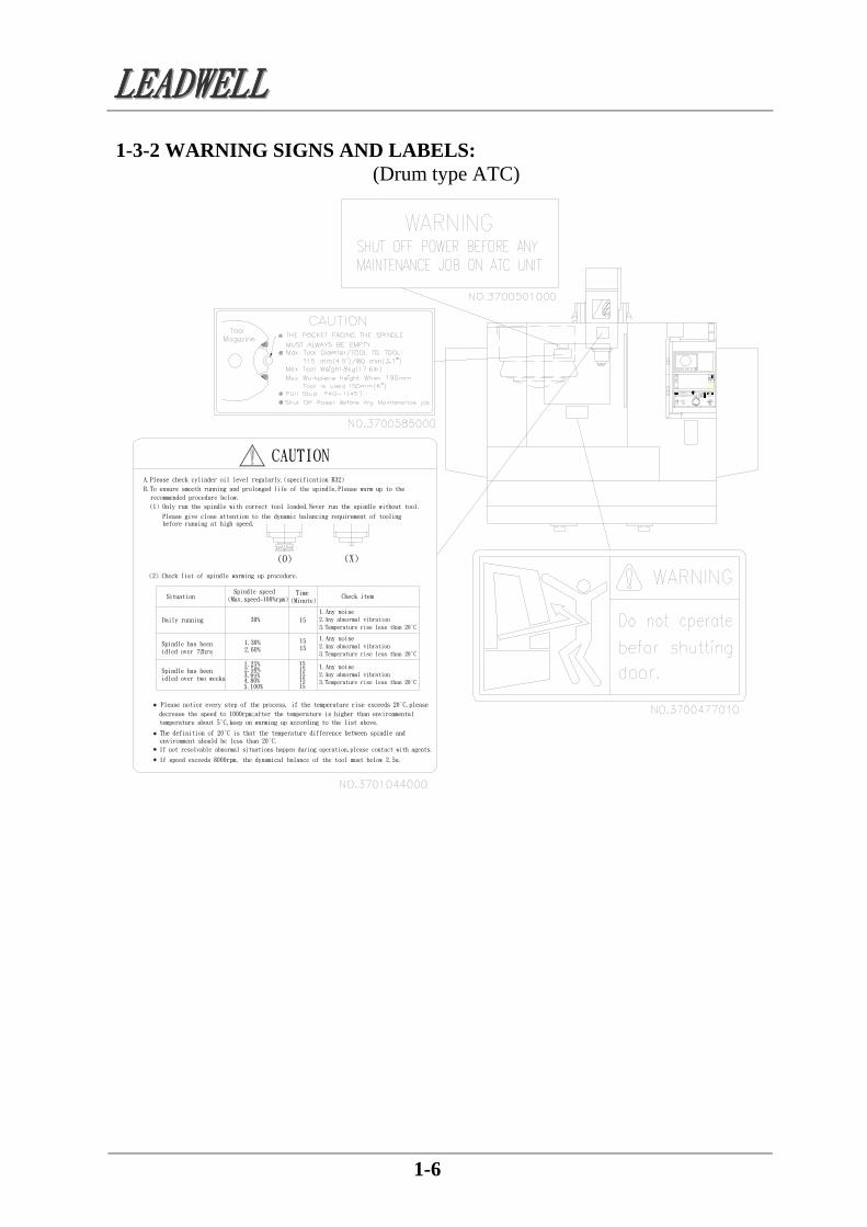
1-3-2 WARNING SIGNS AND LABELS: (Drum type ATC)
3.Temperature rise less than 20°Cidled over 72hrs
(Max.speed=100%rpm)Spindle speed
(2) Check list of spindle warming up procedure.
Please give close attention to the dynamic balancing requirement of tooling
(1) Only run the spindle with correct tool loaded.Never run the spindle without tool.
B.To ensure smooth running and prolonged life of the spindle,Please warm up to the
A.Please check cylinder oil level regularly.(specification R32)
before running at high speed.
recommended procedure below.
Spindle has been
Daily running
Situation
30%
2.60%1.30%
CAUTION
1.Any noise2.Any abnormal vibration
3.Temperature rise less than 20°C
2.Any abnormal vibration
1.Any noise
Check item(Minute)Time
(O)
1515
15
(X)
environment should be less than 20°C.
temperature about 5°C,keep on warming up according to the list above.
If speed exceeds 8000rpm, the dynamical balance of the tool must below 2.5u.
If not resolvable abnormal situations happen during operation,please contact with agents.
The definition of 20°C is that the temperature difference between spindle and
decrease the speed to 1000rpm;after the temperature is higher than environmental
Please notice every step of the process, if the temperature rise exceeds 20°C,please
Spindle has beenidled over two weeks 4.80%
3.65%2.50%1.25%
5.100%
1.Any noise2.Any abnormal vibration
3.Temperature rise less than 20°C1515151515
LLLEEEAAADDDWWWEEELLLLLL
1-7
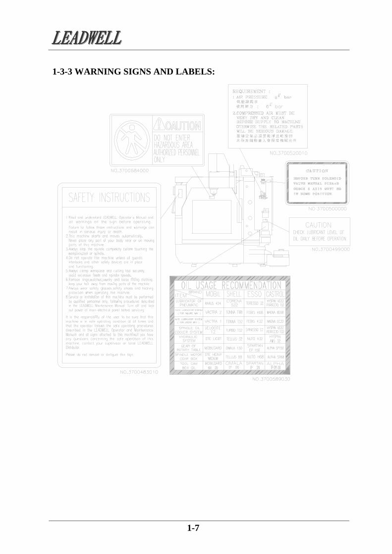
1-3-3 WARNING SIGNS AND LABELS:
LLLEEEAAADDDWWWEEELLLLLL
1-8
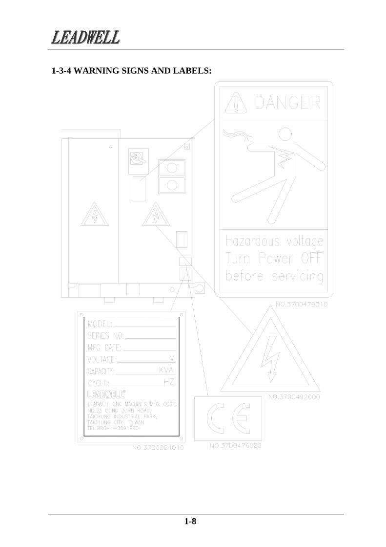
1-3-4 WARNING SIGNS AND LABELS:
LLLEEEAAADDDWWWEEELLLLLL
1-9
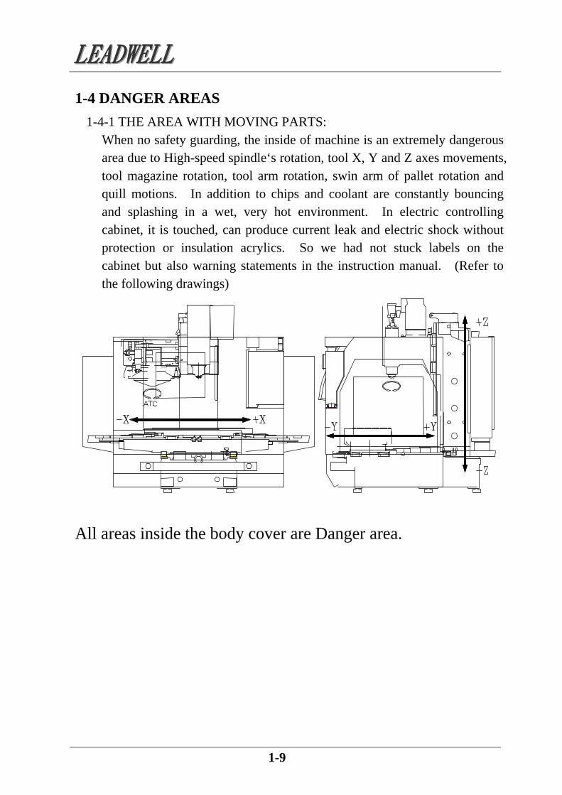
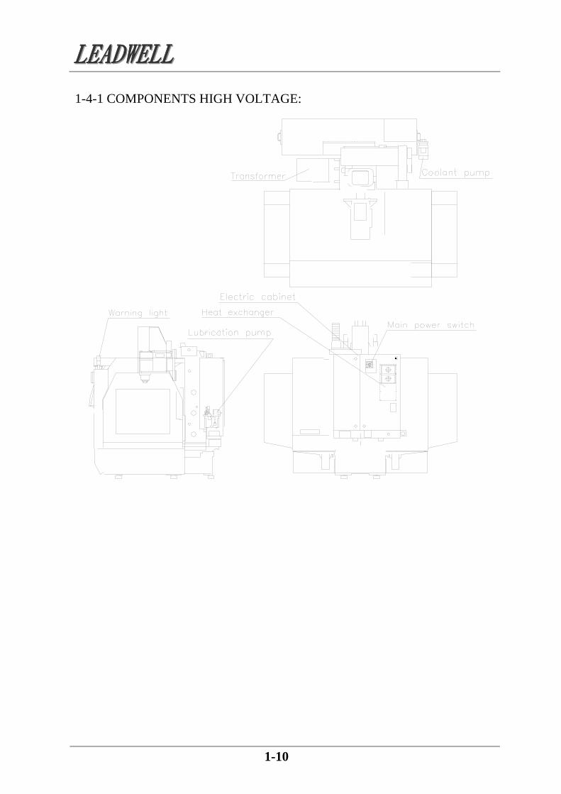
1-4 DANGER AREAS 1-4-1 THE AREA WITH MOVING PARTS:
When no safety guarding, the inside of machine is an extremely dangerous area due to High-speed spindle‘s rotation, tool X, Y and Z axes movements, tool magazine rotation, tool arm rotation, swin arm of pallet rotation and quill motions. In addition to chips and coolant are constantly bouncing and splashing in a wet, very hot environment. In electric controlling cabinet, it is touched, can produce current leak and electric shock without protection or insulation acrylics. So we had not stuck labels on the cabinet but also warning statements in the instruction manual. (Refer to the following drawings)
All areas inside the body cover are Danger area.
LLLEEEAAADDDWWWEEELLLLLL
1-10
1-4-1 COMPONENTS HIGH VOLTAGE:
LLLEEEAAADDDWWWEEELLLLLL
2-1
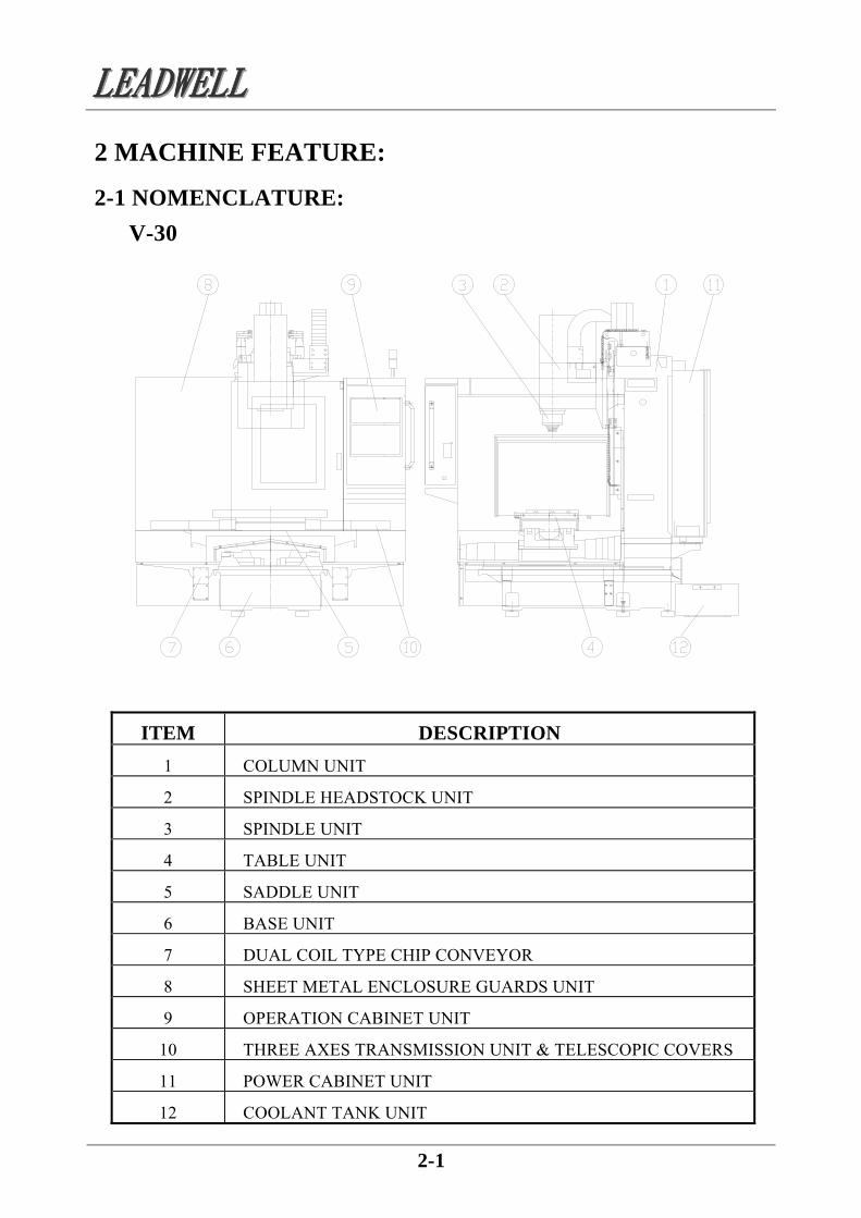
2 MACHINE FEATURE:
2-1 NOMENCLATURE: V-30
ITEM DESCRIPTION
1 COLUMN UNIT
2 SPINDLE HEADSTOCK UNIT
3 SPINDLE UNIT
4 TABLE UNIT
5 SADDLE UNIT
6 BASE UNIT
7 DUAL COIL TYPE CHIP CONVEYOR
8 SHEET METAL ENCLOSURE GUARDS UNIT
9 OPERATION CABINET UNIT
10 THREE AXES TRANSMISSION UNIT & TELESCOPIC COVERS
11 POWER CABINET UNIT
12 COOLANT TANK UNIT
LLLEEEAAADDDWWWEEELLLLLL
2-2
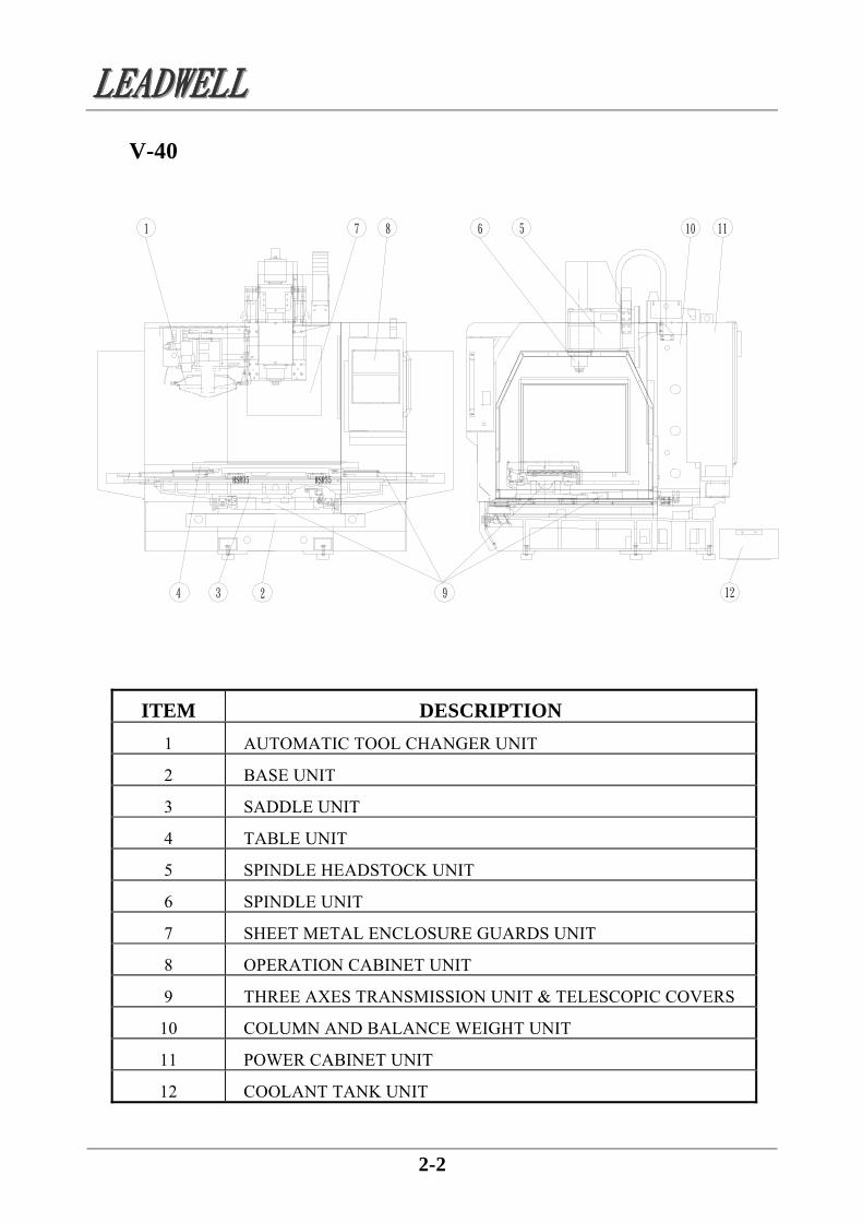
V-40
ITEM DESCRIPTION
1 AUTOMATIC TOOL CHANGER UNIT
2 BASE UNIT
3 SADDLE UNIT
4 TABLE UNIT
5 SPINDLE HEADSTOCK UNIT
6 SPINDLE UNIT
7 SHEET METAL ENCLOSURE GUARDS UNIT
8 OPERATION CABINET UNIT
9 THREE AXES TRANSMISSION UNIT & TELESCOPIC COVERS
10 COLUMN AND BALANCE WEIGHT UNIT
11 POWER CABINET UNIT
12 COOLANT TANK UNIT
LLLEEEAAADDDWWWEEELLLLLL
2-3
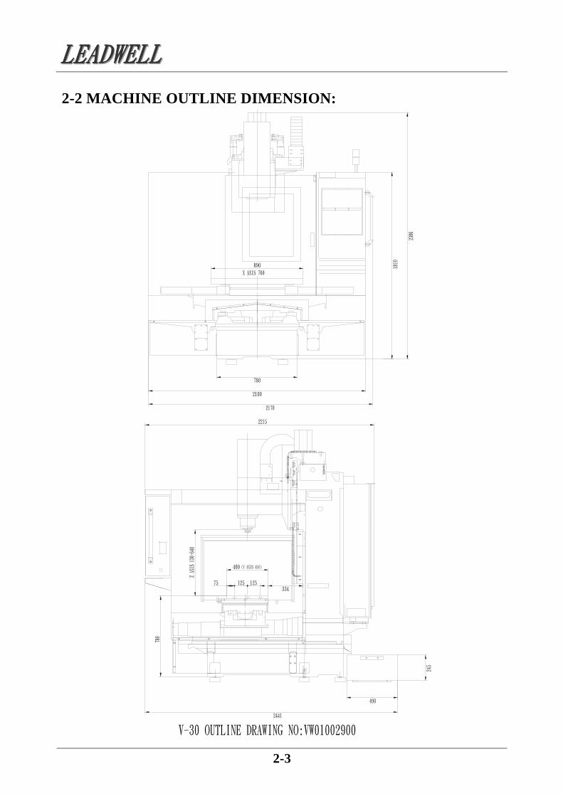
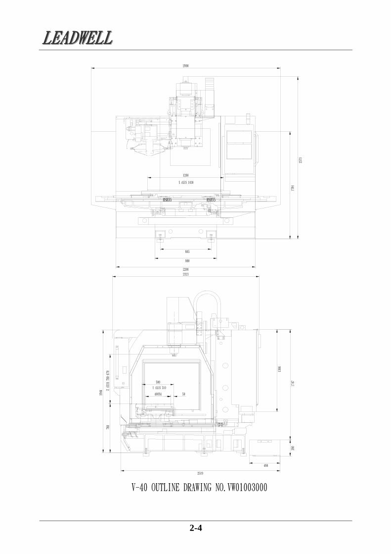
2-2 MACHINE OUTLINE DIMENSION:
LLLEEEAAADDDWWWEEELLLLLL
2-4
LLLEEEAAADDDWWWEEELLLLLL
2-5
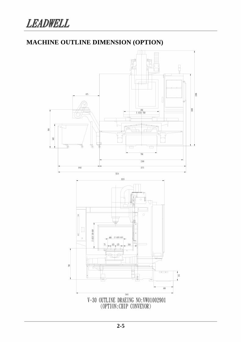
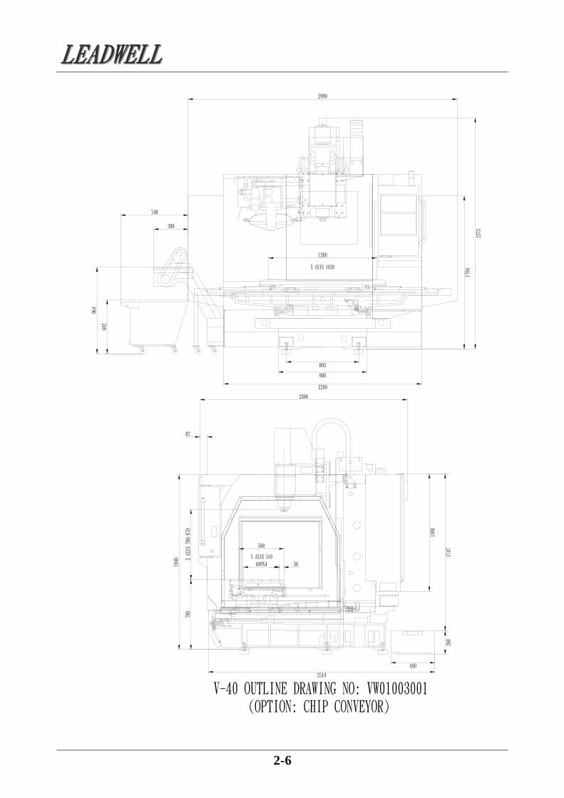
MACHINE OUTLINE DIMENSION (OPTION)
LLLEEEAAADDDWWWEEELLLLLL
2-6

LLLEEEAAADDDWWWEEELLLLLL
2-7
2-3 SPECIFICATION OF MACHINE: V-30
Capacity
X-axis travel mm(in) 760(30)
Y-axis travel mm(in) 410(16)
Z-axis travel mm(in) 410 (16)
Distance from table(pallet) top to spindle end mm(in) 130-540(5.1-21.3)
Distance from column front to spindle center mm(in) 438(17)
Table
Size of working surface mm(in)xmm(in) 890x400(35x15.7)
Permissible mass of workpiece kg(lb) 300(660)
Table working surface configuratin mm(in) 18Tx125x3
Height from floor to table top mm(in) 830(32.6)
Spindle
Spindle speeds min-1 8000
Number of spindle speed ranges 1
Spindle nose(nominal size,NO.) 7/24 Taper,NO40
Spindle bearing inner diameter mm(in) 70 (2.75)
Ratios 1:1
Max. spindle torque N.M(ft.lbf) 95.5(70.4)
Transmission H.T.D Belt
Tool clamping force Kg(lb) 800 (1760)
Feedrate
Rapid traverse m/min(IPM) 20/20/15(66/66/50)
Feedrate m/min(IPM) 5(16.6)
Jog feedrate mm/min(IPM) 1260(49.6)
A.T.C Drum type Arm type Tool shank(nominal size,NO.) BT-40
Retention knob(nominal size,NO.) MAS-P40T-I,JIS-B-6339
Tool storage capacity 20 24
Max. tool diameter(with adjacent tools) mm(in) 95(3.7) 80(3.15)
Max. tool diameter(without adjacent tools) mm(in) 150(5.9) 110(4.3)
Max. tool mass kg(lb) 7(15.4) 7(15.4)
Max. tool length mm(in) 250(9.8) 250(9.8)
Tool change time(tool to tool) sec 7.5 3
Tool change time(chip to chip) sec 13 10
Tool selection Random

LLLEEEAAADDDWWWEEELLLLLL
2-8
A.P.C
Number of pallets ---
Method of pallet change ---
Pallet changing time sec ---
MAG drive method ---
Motors FANUC Motor typeSpindle motor(30min/cont) KW(HP) 7.5(10) αp12/8000i
X-axis feed motor KW(HP) 1.2(1.6) αc8/2000i
Const torque Nm 8
Thrust force Kgf 410
Ball screw mm Ψ36xP10x1248L
Goo-G G 0.23
Y-axis feed motor KW(HP) 1.2(1.6) αc8/2000i
Const torque Nm 8
Thrust force Kgf 410
Ball screw mm ψ40xP10x888L
Goo-G G 0.23
Z-axis feed motor KW(HP) 1.8(2.4) αc12/2000i
Const torque Nm 12
Thrust force Kgf 610
Ball screw mm ψ40xP10x1120L
Goo-G G 0.175
Hydraulic pump motor KW(HP)---
Lubricant pump motor W4
Coolant pump motor KW(HP)50HZ-0.5(0.67) / 60HZ-0.76(1)
Guide way
X guide way LG24-35-1640L-2
Width mm(in) 334 (13.1)
Guide distance mm(in) 472 (18.5)
Y guide way LG24-35-1000L-2
Width mm(in) 694 (27.3)
Guide distance mm(in) 445.5 (17.5)
Z guide way LG24-35-1080L-2
Width mm(in) 434 (17)
Guide distance mm(in) 464 (18.2)
Power sources
Electrical power supply KVA 25
LLLEEEAAADDDWWWEEELLLLLL
2-9
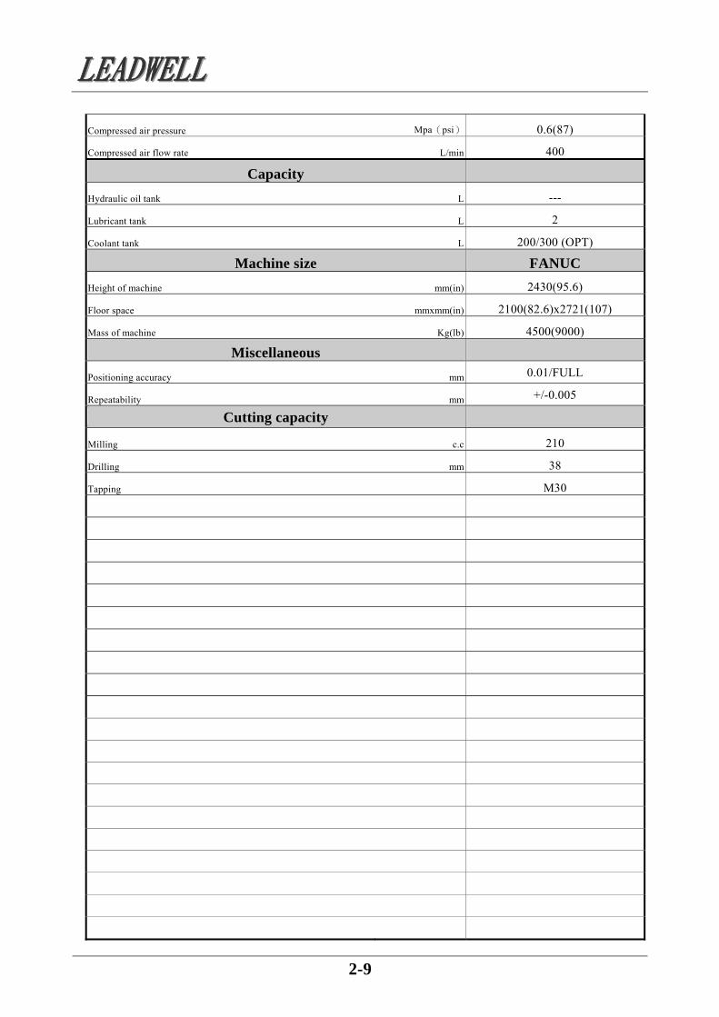
Compressed air pressure Mpa(psi) 0.6(87)
Compressed air flow rate L/min 400
Capacity
Hydraulic oil tank L ---
Lubricant tank L 2
Coolant tank L 200/300 (OPT)
Machine size FANUC Height of machine mm(in) 2430(95.6)
Floor space mmxmm(in) 2100(82.6)x2721(107)
Mass of machine Kg(lb) 4500(9000)
Miscellaneous
Positioning accuracy mm 0.01/FULL
Repeatability mm +/-0.005
Cutting capacity
Milling c.c 210
Drilling mm 38
Tapping M30
LLLEEEAAADDDWWWEEELLLLLL
2-10
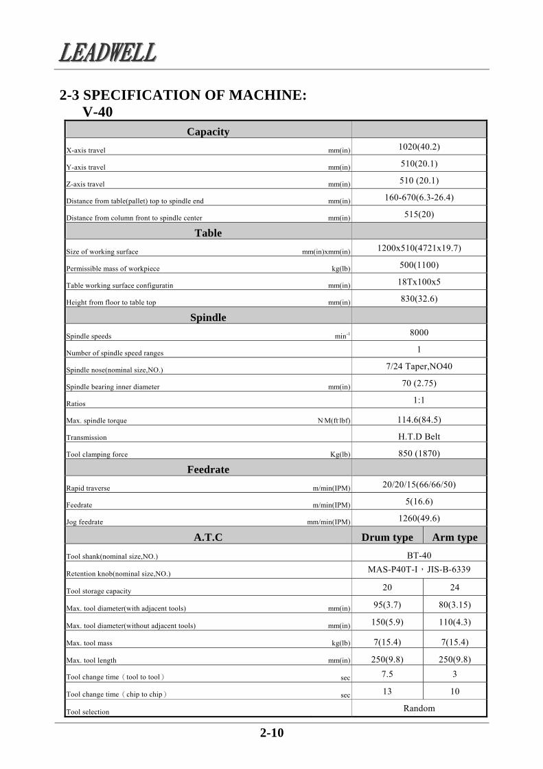
2-3 SPECIFICATION OF MACHINE: V-40
Capacity
X-axis travel mm(in) 1020(40.2)
Y-axis travel mm(in) 510(20.1)
Z-axis travel mm(in) 510 (20.1)
Distance from table(pallet) top to spindle end mm(in) 160-670(6.3-26.4)
Distance from column front to spindle center mm(in) 515(20)
Table
Size of working surface mm(in)xmm(in) 1200x510(4721x19.7)
Permissible mass of workpiece kg(lb) 500(1100)
Table working surface configuratin mm(in) 18Tx100x5
Height from floor to table top mm(in) 830(32.6)
Spindle
Spindle speeds min-1 8000
Number of spindle speed ranges 1
Spindle nose(nominal size,NO.) 7/24 Taper,NO40
Spindle bearing inner diameter mm(in) 70 (2.75)
Ratios 1:1
Max. spindle torque N.M(ft.lbf) 114.6(84.5)
Transmission H.T.D Belt
Tool clamping force Kg(lb) 850 (1870)
Feedrate
Rapid traverse m/min(IPM) 20/20/15(66/66/50)
Feedrate m/min(IPM) 5(16.6)
Jog feedrate mm/min(IPM) 1260(49.6)
A.T.C Drum type Arm type Tool shank(nominal size,NO.) BT-40
Retention knob(nominal size,NO.) MAS-P40T-I,JIS-B-6339
Tool storage capacity 20 24
Max. tool diameter(with adjacent tools) mm(in) 95(3.7) 80(3.15)
Max. tool diameter(without adjacent tools) mm(in) 150(5.9) 110(4.3)
Max. tool mass kg(lb) 7(15.4) 7(15.4)
Max. tool length mm(in) 250(9.8) 250(9.8)
Tool change time(tool to tool) sec 7.5 3
Tool change time(chip to chip) sec 13 10
Tool selection Random
LLLEEEAAADDDWWWEEELLLLLL
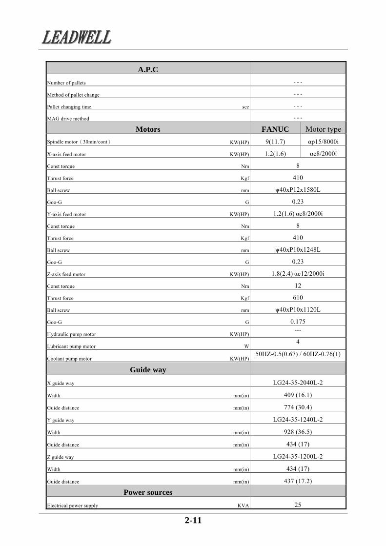
2-11
A.P.C
Number of pallets ---
Method of pallet change ---
Pallet changing time sec ---
MAG drive method ---
Motors FANUC Motor typeSpindle motor(30min/cont) KW(HP) 9(11.7) αp15/8000i
X-axis feed motor KW(HP) 1.2(1.6) αc8/2000i
Const torque Nm 8
Thrust force Kgf 410
Ball screw mm ψ40xP12x1580L
Goo-G G 0.23
Y-axis feed motor KW(HP) 1.2(1.6) αc8/2000i
Const torque Nm 8
Thrust force Kgf 410
Ball screw mm ψ40xP10x1248L
Goo-G G 0.23
Z-axis feed motor KW(HP) 1.8(2.4) αc12/2000i
Const torque Nm 12
Thrust force Kgf 610
Ball screw mm ψ40xP10x1120L
Goo-G G 0.175
Hydraulic pump motor KW(HP)---
Lubricant pump motor W4
Coolant pump motor KW(HP)50HZ-0.5(0.67) / 60HZ-0.76(1)
Guide way
X guide way LG24-35-2040L-2
Width mm(in) 409 (16.1)
Guide distance mm(in) 774 (30.4)
Y guide way LG24-35-1240L-2
Width mm(in) 928 (36.5)
Guide distance mm(in) 434 (17)
Z guide way LG24-35-1200L-2
Width mm(in) 434 (17)
Guide distance mm(in) 437 (17.2)
Power sources
Electrical power supply KVA 25
LLLEEEAAADDDWWWEEELLLLLL
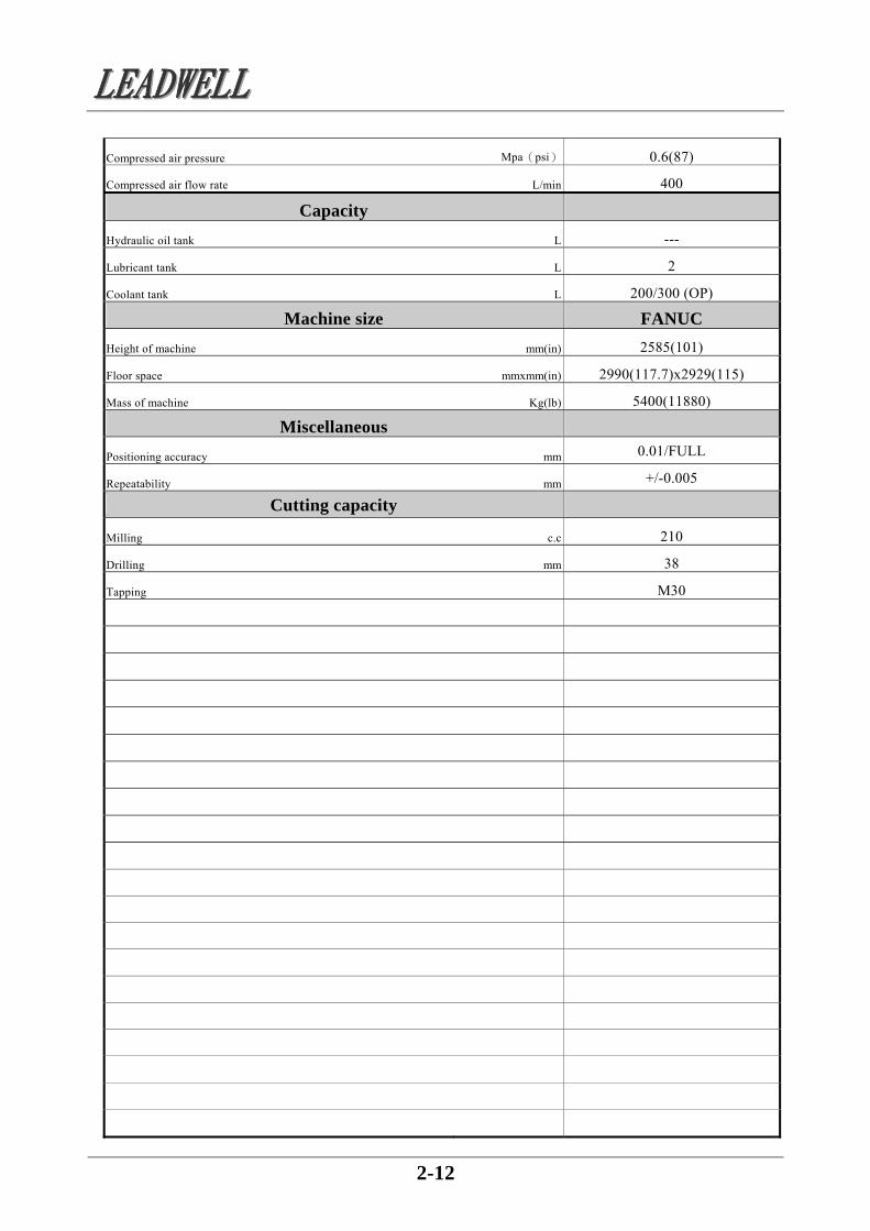
2-12
Compressed air pressure Mpa(psi) 0.6(87)
Compressed air flow rate L/min 400
Capacity
Hydraulic oil tank L ---
Lubricant tank L 2
Coolant tank L 200/300 (OP)
Machine size FANUC Height of machine mm(in) 2585(101)
Floor space mmxmm(in) 2990(117.7)x2929(115)
Mass of machine Kg(lb) 5400(11880)
Miscellaneous
Positioning accuracy mm 0.01/FULL
Repeatability mm +/-0.005
Cutting capacity
Milling c.c 210
Drilling mm 38
Tapping M30
LLLEEEAAADDDWWWEEELLLLLL
3-1
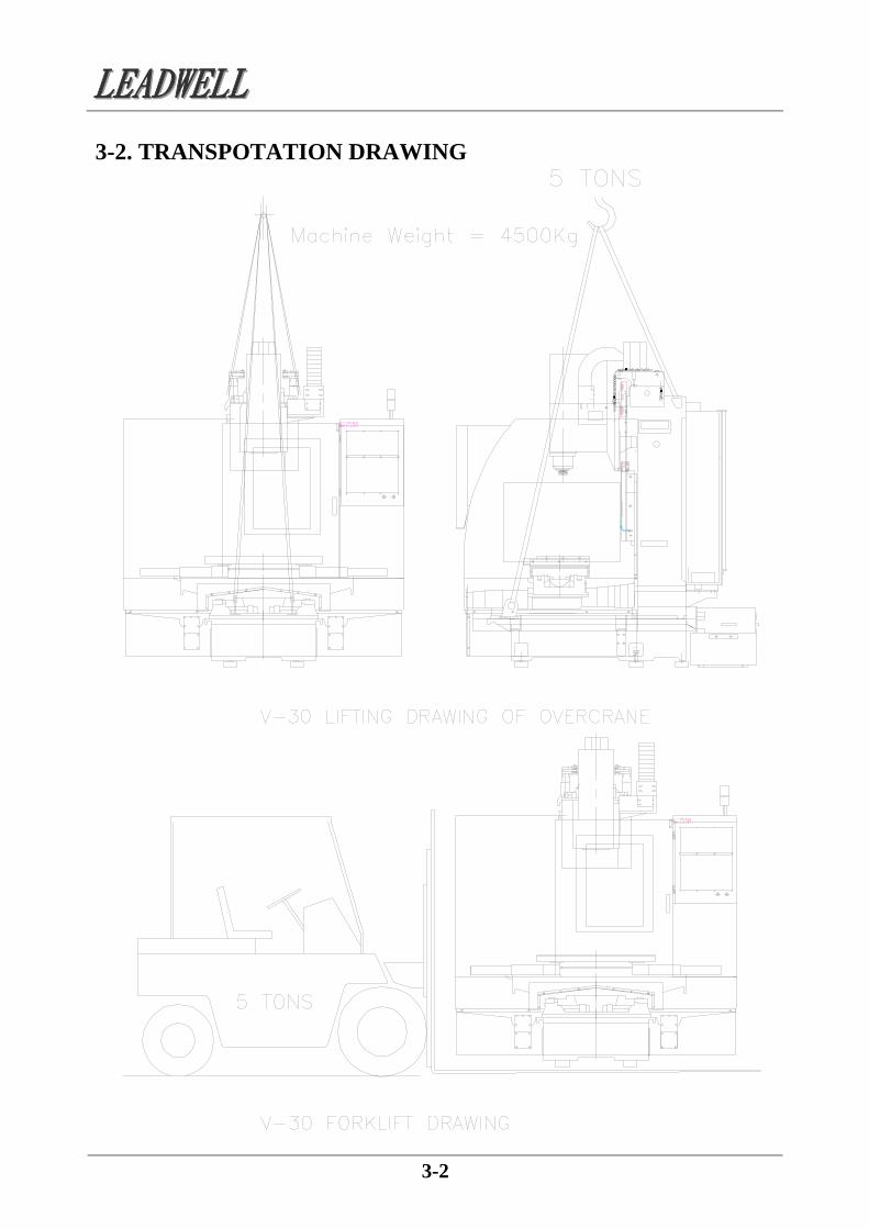
3. TRANSPORTATION:
3-1 PRECAUTION:
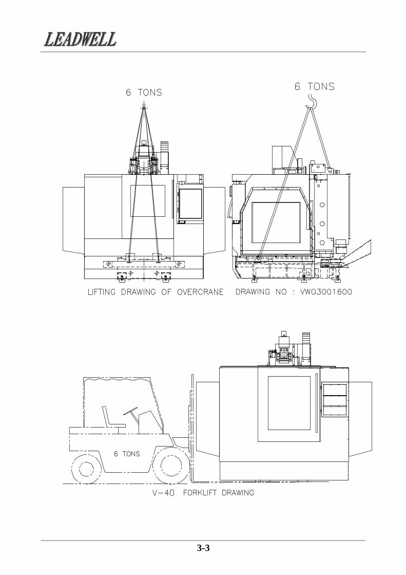
1. Only trained, qualified workers should operate forklift trucks, cranes or similar equipments and apply slings.
2. The wires used to lift should be checked that they are strong enough for the weight of machine center and in good condition. The dimensions of wire ropes specified in manual. (Refer to drawings)
3. Be sure that the wires will not come into contact with any delicate parts of machine center. Preotect machine by placing cloths or wooden blocks.
4. Before hoisting the machine, make sure all moving units are fixed in place.
5. Be careful and avoid the hoisting wires contacting with any piping, unit, parts, electric cables.
6. Check around the site of machine and make it clean, proper to be installed, that is, User may keep machine away from jolts during move or transport machine.
7. Always inspect slings, chains, hoists or other lifting devices prior to us and never work on a component while it is hanging from a crane or other lifting mechanism.
8. The floor of machine located must be firm, in order to ensure vibration free and secure fastening. Should the floor not be firm, a concrete foundation is recommended.
9. Keep the machine‘s center of gravity at the center of the forks.
Refer to the next page drawings for hoisting.
LLLEEEAAADDDWWWEEELLLLLL
3-2
3-2. TRANSPOTATION DRAWING
LLLEEEAAADDDWWWEEELLLLLL
3-3
LLLEEEAAADDDWWWEEELLLLLL
3-4
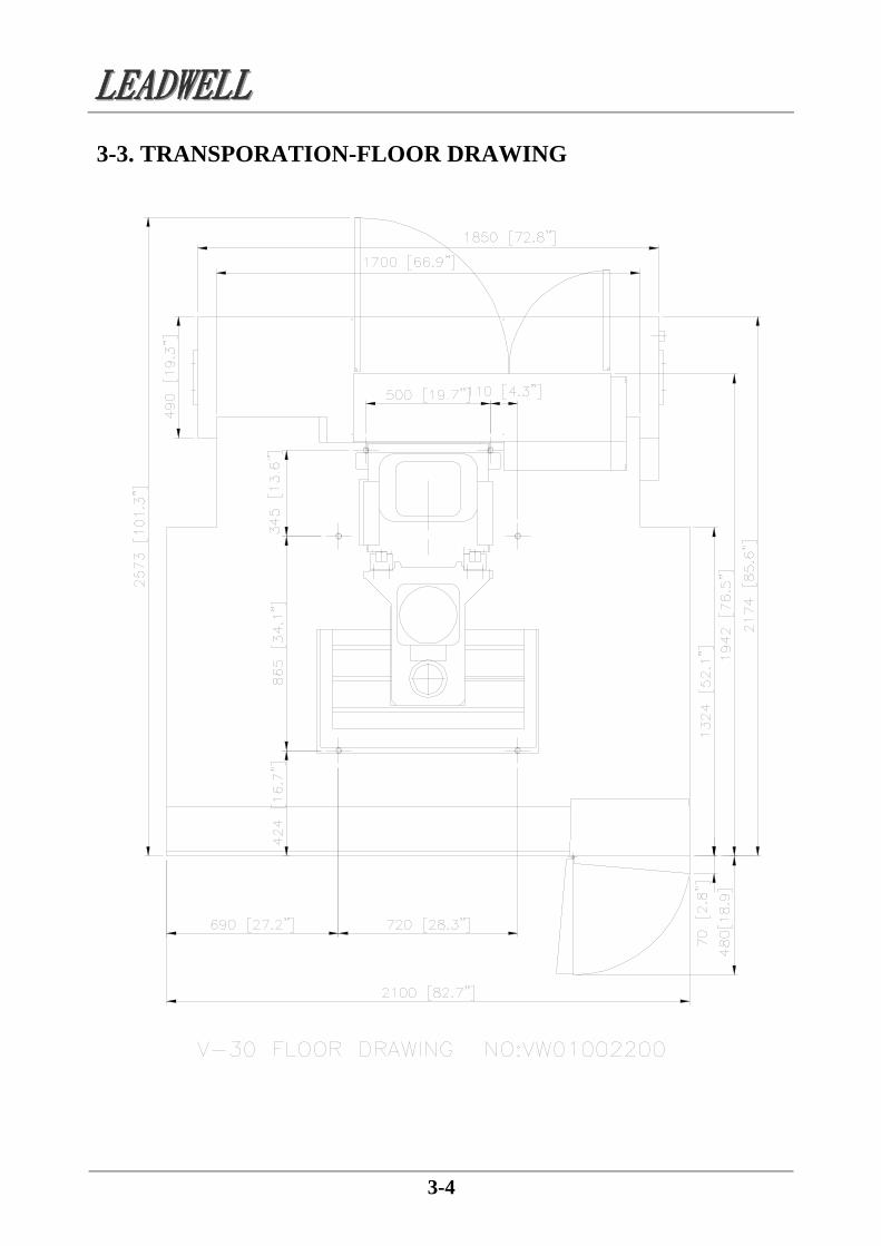
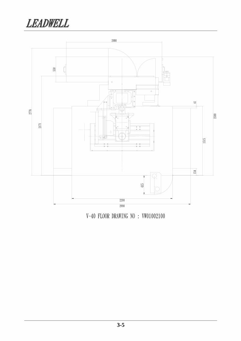
3-3. TRANSPORATION-FLOOR DRAWING
LLLEEEAAADDDWWWEEELLLLLL
3-5

LLLEEEAAADDDWWWEEELLLLLL
4-1
4. INSTALLATION AND PREPARTION:
4-1 PRECATION:
1. Only trained, qualified workers should operate forklift trucks, cranes or similar equipment and apply slings.
2. Use only wires of dimensions specified in the manual. They must be strong enough to support the weight of the machine.
3. Before hoisting the machine, make sure that each of the units is fixed securely.
4. Be careful during remove the machine to proper site and install it.
5. Keep clean around the machine and floor.
6. be sure electrical cables and wire will not be damaged during installing machine.
7. After installation and clean, connect the wire to the power source and ensure the requirement of power capacity is proper.
8. Before using, remove the anti-rusty oil by rags with paraffin or fueloil. Toluene compounds must not be used.
4-2. ENVIRONMENTAL REQUIREMENT:
1. Where the machine avoid exposing to the direct sunlight and/or near to a heat source, etc.. Ambient temperature during operation should be 0 thru 40℃.
2. Avoid a location where the humidity is considerable fluctuating and/or it is highly humid, normally 75﹪ and below in relative humidity.
3. Avoid using the machine under such invironments as to be specially dustful and/or to have a vaporous. organic corrosive gas highly concentrated.
4. Where there is no vibration source in the surroundings.
5. Flat and smooth ground without dust or other particles. The required bearing pressure of the floor is at least 5000kg/㎡.
6. The machine must be protected from electrical noise sources, such as electric welders and an electric discharge machines.
7. Always ground machine independently, the ground resistance is 100 ohms or less and the length of ground cable is as short as possible.
8. The sound pressure level at the operator‘s position is under 85 dbA.
9. Foundation should be constructed of either, reinforced or non-reinforced concrete with thickness and consistency compatible to industry standards for machine weight.
LLLEEEAAADDDWWWEEELLLLLL
4-2
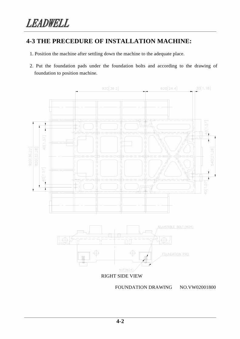
4-3 THE PRECEDURE OF INSTALLATION MACHINE:
1. Position the machine after settling down the machine to the adequate place.
2. Put the foundation pads under the foundation bolts and according to the drawing of foundation to position machine.
RIGHT SIDE VIEW
FOUNDATION DRAWING NO.VW02001800

LLLEEEAAADDDWWWEEELLLLLL
4-3
3. Remove all the fixed blocks and screws:
a. Take away the fixed screws of counter balance in column.
b. Remove the fixed blocks between saddle and base.
c. Remove the fixed blocks between saddle and transmission bracket of Y-axis.
d. Remove the fixed block under ATC.
e. After power on, let headstock upward a little bit to remove the supported block under spindle.
f. Use MPG and let spindle headstock downward a little bit, then take away the rod of counter balance in column.
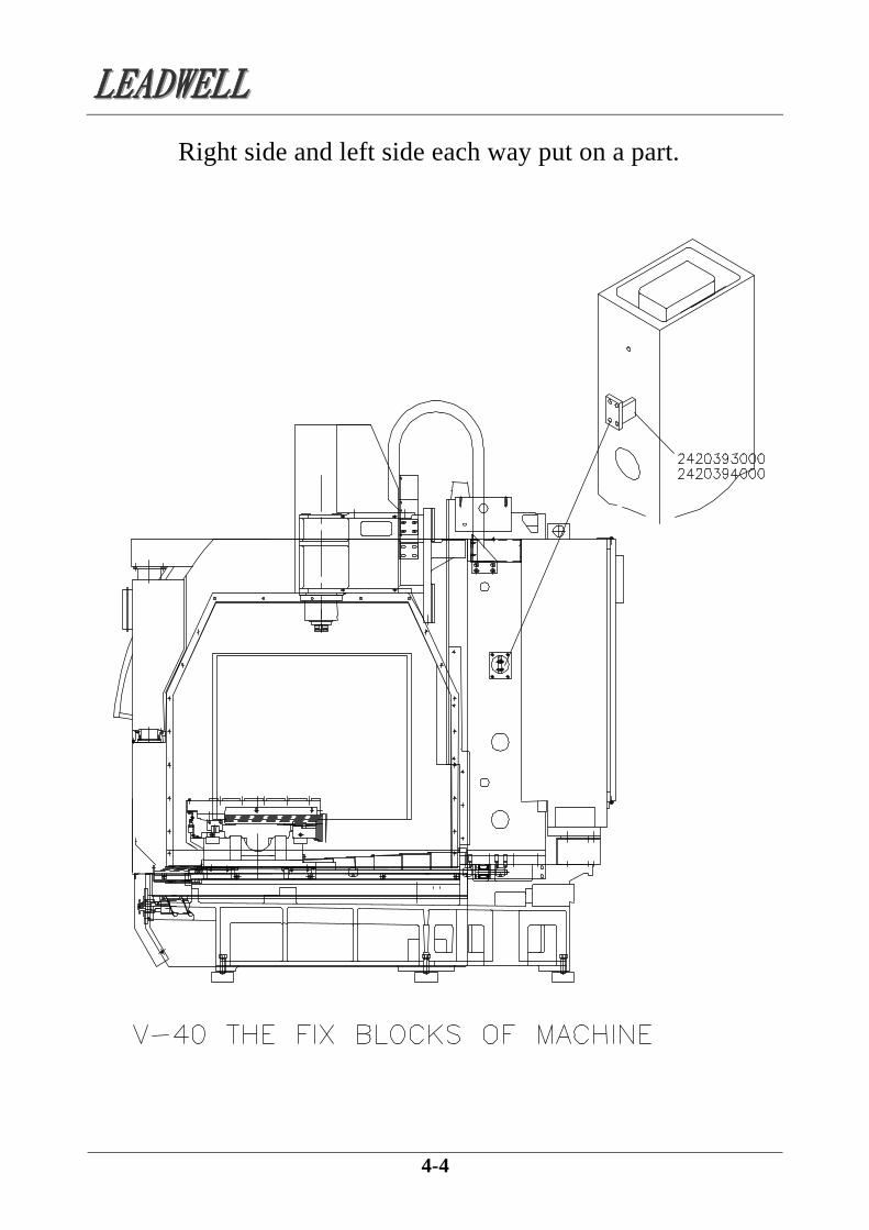
g. Put on the 2 parts on the machine for column.(Refer to the next page following drawing.)
Refer to the following drawings.
V-40 THE FIXBLOCKS OF MANCHINE
LLLEEEAAADDDWWWEEELLLLLL
4-4
Right side and left side each way put on a part.
LLLEEEAAADDDWWWEEELLLLLL
4-5
4. Install the accessaries:
a. Lock up the front telescopic cover of y-axis.
b. Mount on the front cover of table.
c. Lock up the left side cover of enclosure.
d. Mount the protecting cover on ATC.
e. Pipe coolant pump and coolant tank after settling down the coolant tank.
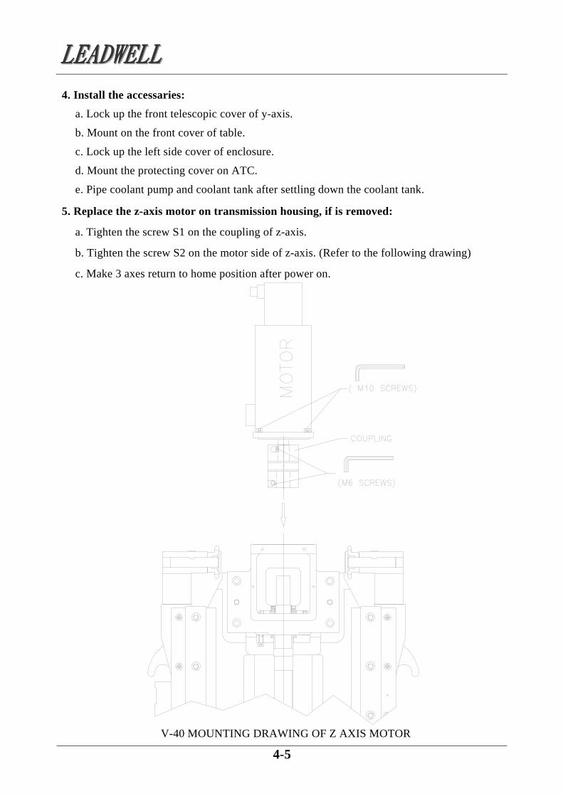
5. Replace the z-axis motor on transmission housing, if is removed:
a. Tighten the screw S1 on the coupling of z-axis.
b. Tighten the screw S2 on the motor side of z-axis. (Refer to the following drawing)
c. Make 3 axes return to home position after power on.
V-40 MOUNTING DRAWING OF Z AXIS MOTOR

LLLEEEAAADDDWWWEEELLLLLL
4-6
6. THE PROCEDURE OF ADJUSTING LEVEL :
1. Let three axes return to the home position.
2. Clean the table surface and put the levels gauge on just as the drawing shown.
3. Adjust the foundation bolts and nuts to make the foundation bolts locate within the slot of pad.
4. Move X axis to 510mm and Y axis to -255mm . Adjust the foundation bolts and ensure the
bubbles of level gauges in the middle position or keep the deviation within 0.01 mm.
5. Move Y axis to the zero position and -510mm(for V-40) by adjusting the bolts and nuts to make the difference between the two points within 0.01 mm(V1) /0.04 mm(V2).
6. After returning Y axis to -255mm, move X axis to zero position and1020mm. The difference value between two points should be within 0.05 mm(V1)/0.04mm(V2).
7. Tighten the foundation bolts and nuts.
LLLEEEAAADDDWWWEEELLLLLL
4-7
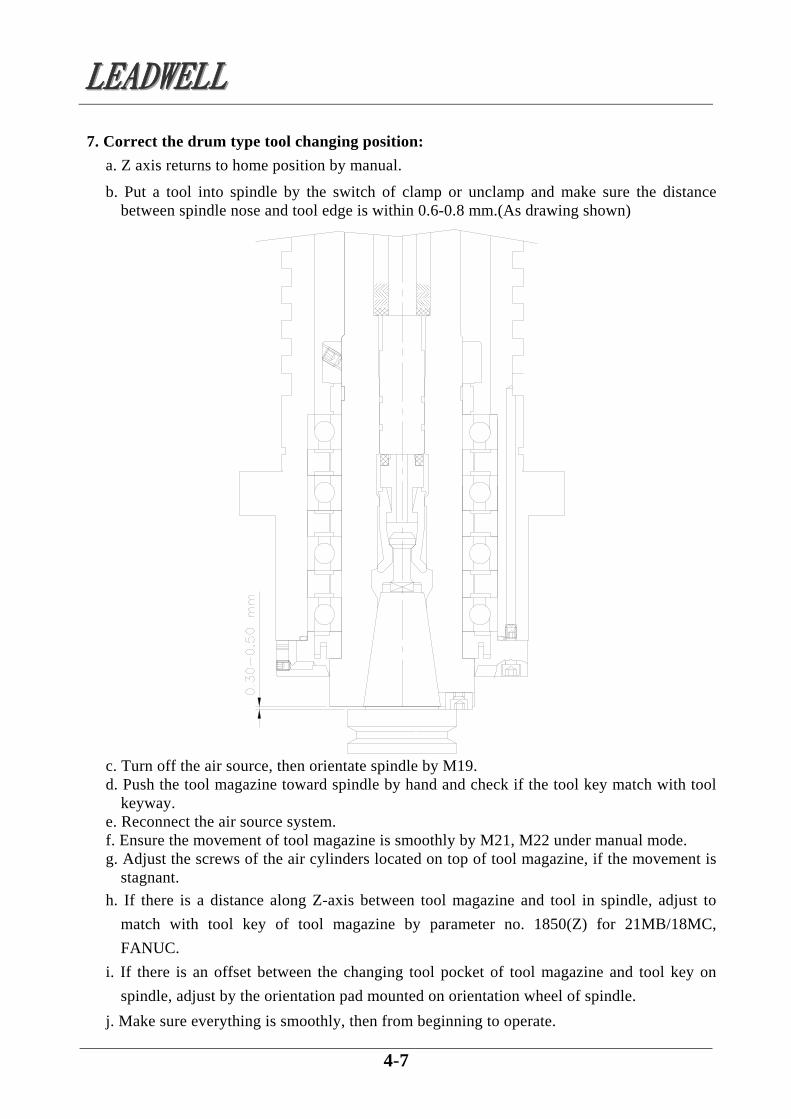
7. Correct the drum type tool changing position: a. Z axis returns to home position by manual.
b. Put a tool into spindle by the switch of clamp or unclamp and make sure the distance between spindle nose and tool edge is within 0.6-0.8 mm.(As drawing shown)
c. Turn off the air source, then orientate spindle by M19. d. Push the tool magazine toward spindle by hand and check if the tool key match with tool
keyway. e. Reconnect the air source system. f. Ensure the movement of tool magazine is smoothly by M21, M22 under manual mode. g. Adjust the screws of the air cylinders located on top of tool magazine, if the movement is
stagnant. h. If there is a distance along Z-axis between tool magazine and tool in spindle, adjust to
match with tool key of tool magazine by parameter no. 1850(Z) for 21MB/18MC, FANUC.
i. If there is an offset between the changing tool pocket of tool magazine and tool key on spindle, adjust by the orientation pad mounted on orientation wheel of spindle.
j. Make sure everything is smoothly, then from beginning to operate.
LLLEEEAAADDDWWWEEELLLLLL
4-8
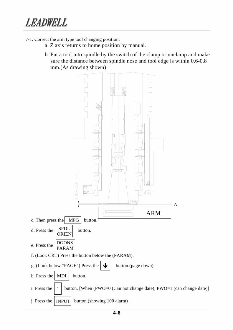
7-1. Correct the arm type tool changing position: a. Z axis returns to home position by manual.
b. Put a tool into spindle by the switch of the clamp or unclamp and make sure the distance between spindle nose and tool edge is within 0.6-0.8 mm.(As drawing shown)
c. Then press the MPG button.
A
ARM
d. Press the button. SPDLORIEN
e. Press the DGONS PARAM
f. (Look CRT) Press the button below the (PARAM).
g. (Look below “PAGE”) Press the button.(page down)
h. Press the button. MDI
i. Press the button. [When (PWO=0 (Can not change date), PWO=1 (can change date)] 1
j. Press the button.(showing 100 alarm) INPUT
LLLEEEAAADDDWWWEEELLLLLL
4-9
k. Press the button DGONSPARAM
l. (Looking CRT) Press the button below the (DGNOS)
l. press the button. LNO. Q P
m. Press the buttons.(normal D0525 10000000) 2 5 5
n. Press the button. INPUT
o. Press the 1 0 1 1 0 0 0 0 bottons.
p. Press the INPUT buttons.(after finish change it back to D0525 10000000)
q. (Make sure the spindle nose higher than arm‘s top) Press the MPG then press the
buttons.
r. (When you press the button the arm will be move, so take care of you fingers) CYCLE
SP
s. Make sure the distance between spindle nose and arm‘s top is within (BT type 5.90±0.05mm. (for CAT type is 3.3±0.05mm)
(If you want to arm to reverse, change the D0526 00100000 to D0526 00100001 then press
the button .(before you press the “cycle start ” button take care of your fingers.)
t. Change the DGNOS “D0525 10000000” and “D0526 00100000” and PARAM “PWO=0” BACK
u. Press the MDI M 6 buttons.(for test auto tool change)
CYCLE START
/.# EOB
LLLEEEAAADDDWWWEEELLLLLL
5-1
5. KEY PARTS FEATURES
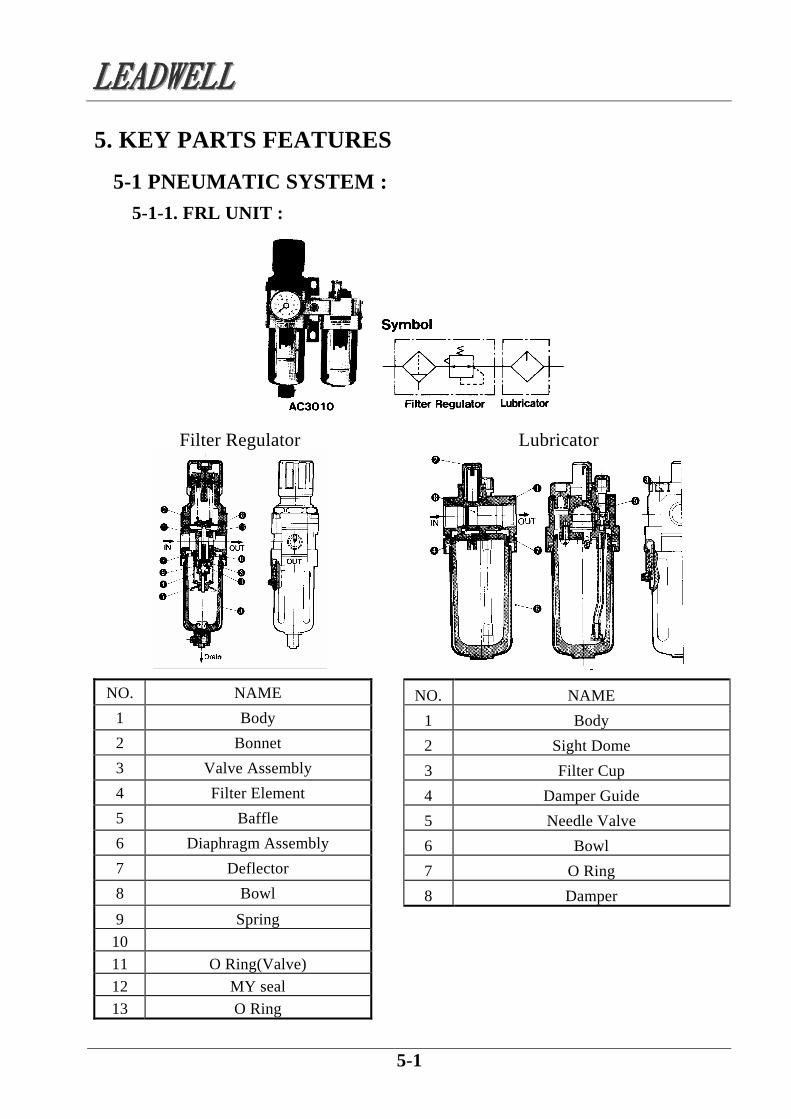
5-1 PNEUMATIC SYSTEM : 5-1-1. FRL UNIT :
Filter Regulator
Lubricator
NO. NAME NO. NAME 1 Body 1 Body 2 Bonnet 2 Sight Dome 3 Valve Assembly 3 Filter Cup 4 Filter Element 4 Damper Guide 5 Baffle 5 Needle Valve 6 Diaphragm Assembly 6 Bowl 7 Deflector 7 O Ring 8 Bowl 8 Damper 9 Spring
10 11 O Ring(Valve) 12 MY seal 13 O Ring
LLLEEEAAADDDWWWEEELLLLLL
5-2
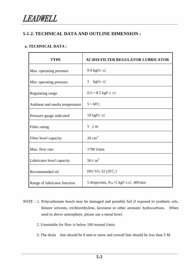
5-1-2. TECHNICAL DATA AND OUTLINE DIMENSION :
a. TECHNICAL DATA :
TYPE AC3010 FILTER REGULATOR LUBRICATOR
Max. operating pressure 9.9 kgf/c ㎡
Min. operating pressure 1 kgf/c ㎡
Regulating range 0.5~8.5 kgf/ c ㎡
Ambient and media temperature 5~60℃
Pressure gauge indicated 10 kgf/c ㎡
Filter rating 5 μm
Filter bowl capacity 20 cm3
Max. flow rate 1700 l/min
Lubricator bowl capacity 50 c m3
Recommanded oil ISO VG 32 (20℃)
Range of lubricator function 5 drops/min, PIN=5 kgf/ c㎡, 40l/min
NOTE : 1. Polycarbonate bowls may be damaged and possibly fail if exposed to synthetic oils,
thinner solvents, trichlorethylene, kerosene or other aromatic hydrocarbons. When
used in above atmosphere, please use a metal bowl.
2. Unsuitable for flow is below 100 normal l/min.
3. The drain line should be 8 mm or more and overall line should be less than 5 M.
LLLEEEAAADDDWWWEEELLLLLL
5-3
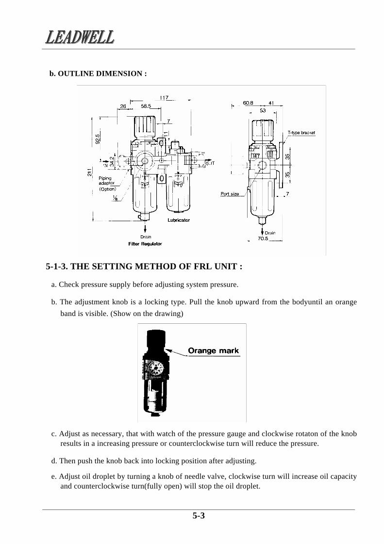
b. OUTLINE DIMENSION :
5-1-3. THE SETTING METHOD OF FRL UNIT :
a. Check pressure supply before adjusting system pressure.
b. The adjustment knob is a locking type. Pull the knob upward from the bodyuntil an orange band is visible. (Show on the drawing)
c. Adjust as necessary, that with watch of the pressure gauge and clockwise rotaton of the knob results in a increasing pressure or counterclockwise turn will reduce the pressure.
d. Then push the knob back into locking position after adjusting.
e. Adjust oil droplet by turning a knob of needle valve, clockwise turn will increase oil capacity and counterclockwise turn(fully open) will stop the oil droplet.
LLLEEEAAADDDWWWEEELLLLLL
5-4
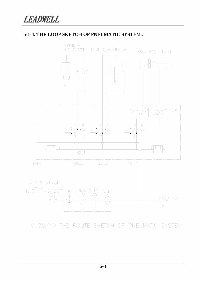
5-1-4. THE LOOP SKETCH OF PNEUMATIC SYSTEM :
LLLEEEAAADDDWWWEEELLLLLL
5-5
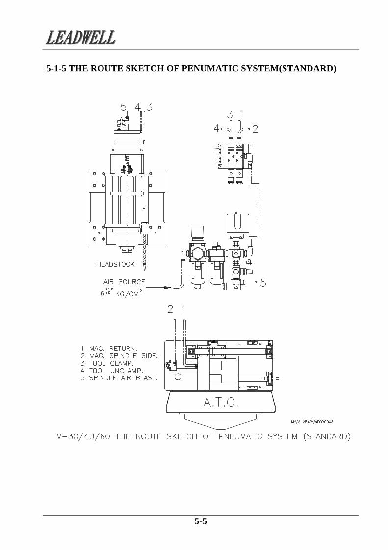
5-1-5 THE ROUTE SKETCH OF PENUMATIC SYSTEM(STANDARD)
LLLEEEAAADDDWWWEEELLLLLL
5-6
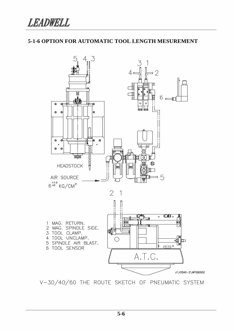
5-1-6 OPTION FOR AUTOMATIC TOOL LENGTH MESUREMENT
LLLEEEAAADDDWWWEEELLLLLL
5-7
5-2 COOLANT SYSTEM:
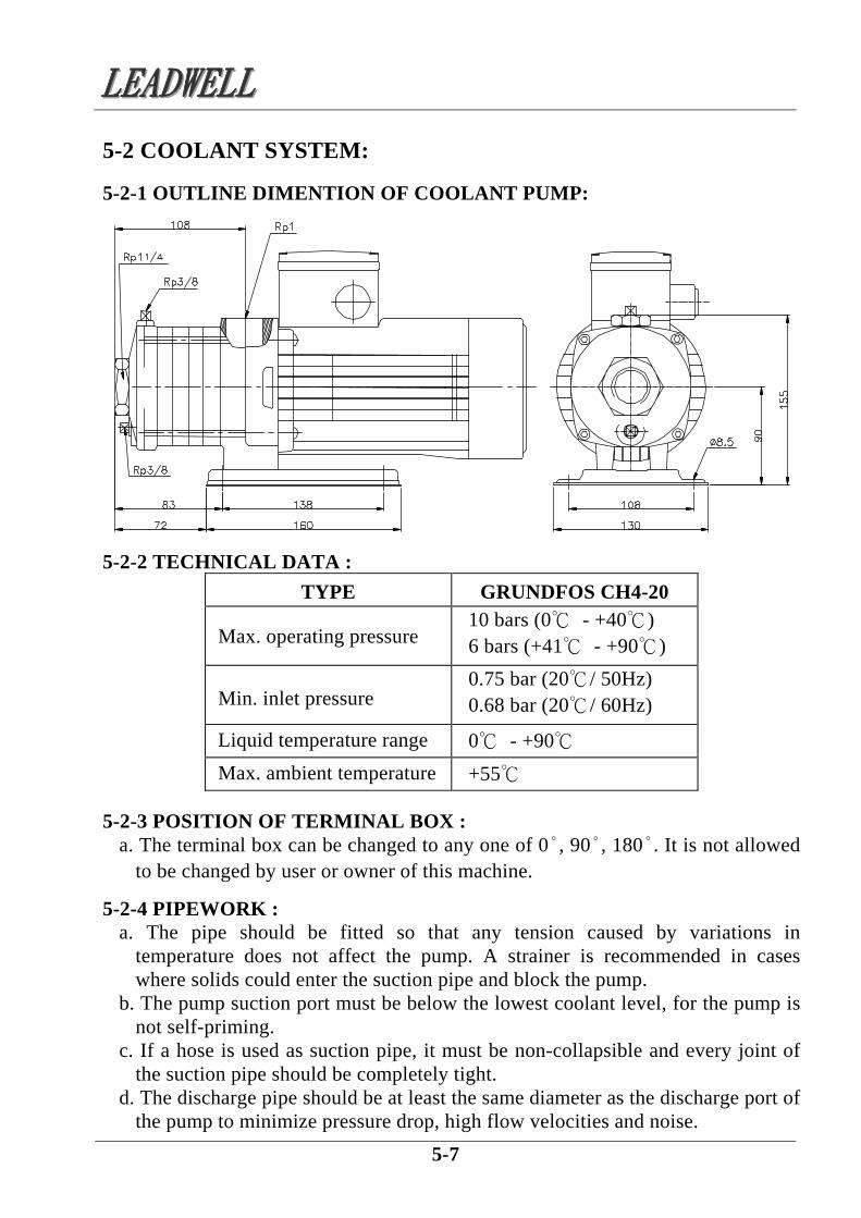
5-2-1 OUTLINE DIMENTION OF COOLANT PUMP:
5-2-2 TECHNICAL DATA :
TYPE GRUNDFOS CH4-20
Max. operating pressure 10 bars (0℃ - +40℃) 6 bars (+41℃ - +90℃)
Min. inlet pressure 0.75 bar (20℃/ 50Hz) 0.68 bar (20℃/ 60Hz)
Liquid temperature range 0℃ - +90℃ Max. ambient temperature +55℃
5-2-3 POSITION OF TERMINAL BOX : a. The terminal box can be changed to any one of 0°, 90°, 180°. It is not allowed
to be changed by user or owner of this machine.
5-2-4 PIPEWORK : a. The pipe should be fitted so that any tension caused by variations in
temperature does not affect the pump. A strainer is recommended in cases where solids could enter the suction pipe and block the pump.
b. The pump suction port must be below the lowest coolant level, for the pump is not self-priming.
c. If a hose is used as suction pipe, it must be non-collapsible and every joint of the suction pipe should be completely tight.
d. The discharge pipe should be at least the same diameter as the discharge port of the pump to minimize pressure drop, high flow velocities and noise.
LLLEEEAAADDDWWWEEELLLLLL
5-8
5-2-5 ELECTRICAL CONNECTIONS : a. The electrical connections should be carried out in accordance with local
regulations. b. The operating voltage and frequency are marked on the nameplate mounted
on pump. c. The pump must be connected to an external on/off switch.
NOTE : Never make any connections in the pump terminal box unless the electricity supply has been switched off.
5-2-6 PHASE OF THE PUMP : a. Signal- phase motor (1x110/220V, 60Hz), do not incorprate motor protection
and must be connected to an approved motor starter. The other incorporate a thermal overload switch and require no additional motor protection.
b. Three-Phases motor must be connected to a motor starter, the set nominal current of which must correspond to the electrical data on the nameplate.
NOTE : 1. Do not start the pump at first time using until it has been filled with coolant.
2. Every connection are made as shown on the inside of the terminal box cover. 3. The pump should rotate counter0clockwise when viewed from the motor end
and arrows on the motor fan‘s cover indicated the correct direction of rotation.
4. To reverse the direction of rotation, switch off the power supply and interchange any two of inputing supply wire.
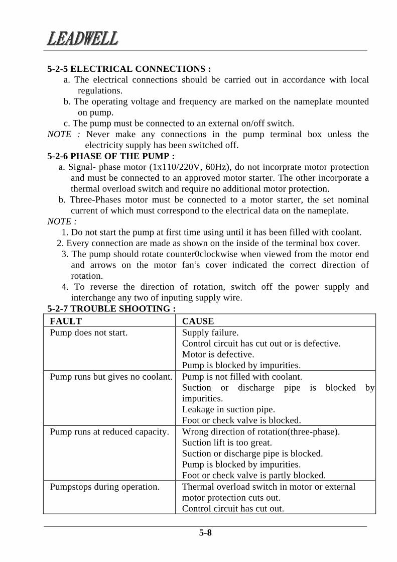
5-2-7 TROUBLE SHOOTING : FAULT CAUSE Pump does not start. Supply failure.
Control circuit has cut out or is defective. Motor is defective. Pump is blocked by impurities.
Pump runs but gives no coolant. Pump is not filled with coolant. Suction or discharge pipe is blocked by impurities. Leakage in suction pipe. Foot or check valve is blocked.
Pump runs at reduced capacity. Wrong direction of rotation(three-phase). Suction lift is too great. Suction or discharge pipe is blocked. Pump is blocked by impurities. Foot or check valve is partly blocked.
Pumpstops during operation. Thermal overload switch in motor or external motor protection cuts out. Control circuit has cut out.
LLLEEEAAADDDWWWEEELLLLLL
5-9
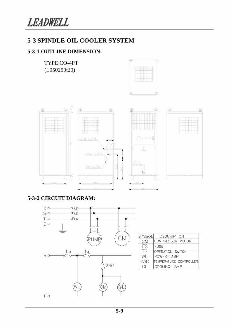
5-3 SPINDLE OIL COOLER SYSTEM
5-3-1 OUTLINE DIMENSION:
TYPE CO-4PT (L050250t20)
5-3-2 CIRCUIT DIAGRAM:
LLLEEEAAADDDWWWEEELLLLLL
5-10
5-3-3 WIRE CONNECTION:
1. Be sure R.S.T are in phase after turning on.
2. Check insulation of compressor and pump before running.
3. 23C temperature meter must set at 25℃.
4. Operation switch should be “ON” position.
5. When the negative phase relay is triggered, reconnect two of R.S.T three lines of power wire.
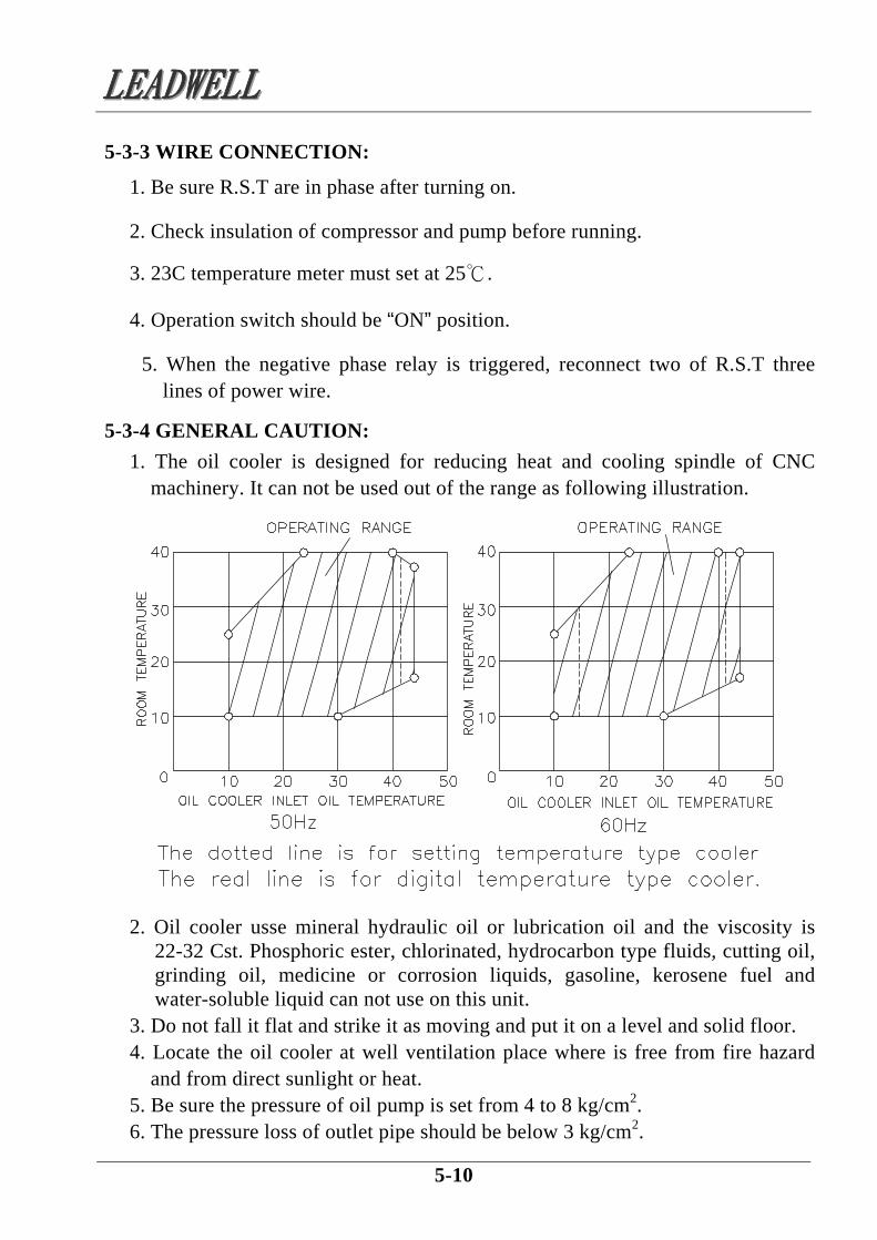
5-3-4 GENERAL CAUTION: 1. The oil cooler is designed for reducing heat and cooling spindle of CNC
machinery. It can not be used out of the range as following illustration.
2. Oil cooler usse mineral hydraulic oil or lubrication oil and the viscosity is
22-32 Cst. Phosphoric ester, chlorinated, hydrocarbon type fluids, cutting oil, grinding oil, medicine or corrosion liquids, gasoline, kerosene fuel and water-soluble liquid can not use on this unit.
3. Do not fall it flat and strike it as moving and put it on a level and solid floor. 4. Locate the oil cooler at well ventilation place where is free from fire hazard
and from direct sunlight or heat. 5. Be sure the pressure of oil pump is set from 4 to 8 kg/cm2. 6. The pressure loss of outlet pipe should be below 3 kg/cm2.
LLLEEEAAADDDWWWEEELLLLLL
5-11
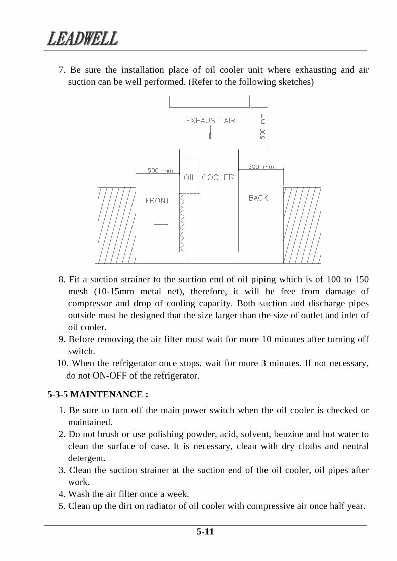
7. Be sure the installation place of oil cooler unit where exhausting and air suction can be well performed. (Refer to the following sketches)
8. Fit a suction strainer to the suction end of oil piping which is of 100 to 150
mesh (10-15mm metal net), therefore, it will be free from damage of compressor and drop of cooling capacity. Both suction and discharge pipes outside must be designed that the size larger than the size of outlet and inlet of oil cooler.
9. Before removing the air filter must wait for more 10 minutes after turning off switch.
10. When the refrigerator once stops, wait for more 3 minutes. If not necessary, do not ON-OFF of the refrigerator.
5-3-5 MAINTENANCE :
1. Be sure to turn off the main power switch when the oil cooler is checked or maintained.
2. Do not brush or use polishing powder, acid, solvent, benzine and hot water to clean the surface of case. It is necessary, clean with dry cloths and neutral detergent.
3. Clean the suction strainer at the suction end of the oil cooler, oil pipes after work.
4. Wash the air filter once a week. 5. Clean up the dirt on radiator of oil cooler with compressive air once half year.
LLLEEEAAADDDWWWEEELLLLLL
5-12
5-3-6 TROUBLE SHOOTING:
SITUATION CAUSE REMEDY Main power turned on, but the indicate lamp is not lit.
Negative phase relay is triggered. Control circuit protector is blown.
Reconnect the wiring. Replace the fuse.
Pump runs but no oil flow and lower oil circulation rate of air.
Joint of oil piping is loosened from suction side.
Check the joint of oil pipe at suction side and tighten the loose joint.
Suction strainer clogged. Clean the suction strainer. Change the oil of oil tank if the oil is contaminated.
The oil level in tank is too low.
Trace and refill up oil.
undue pressure loss in oil pipe cause actuation of relief valve.
Enlarge the oil pipe diameter or trim shortly the piping.
Oil viscosity too high. Choose the appropriate oil.Pump runs but the refrigerator does not work.
Thermostat is OFF. Shift the thermostat setting to the lower side until the refrigerator starts.
Both pump and refrigerator stop.
Control circuit protector failed. Power failure.
Replace the fuse. Check the power source.
Buzzer comes out while refrigerator runs.
Air filter clogged. Obstacle block the suction or exhausting port.
Clean the air filter. Remove the obstacle.
High pressure switch actuated. Thermostat is OFF.
Ambient temperature is too high.
Move the machine to the lower temperature or far from heat source.
Compressor motor overload relay actuated.
Compressor out of order. Replace the compreessor.
NOTE : 1. If alarm does not display, motor still runs but oil is not cool, please record the
situation and ask technical service or local agent right away. 2. Damage from cleaning air filter irregularly is not included quarantee period.
LLLEEEAAADDDWWWEEELLLLLL
5-13
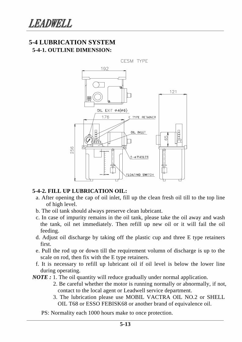
5-4 LUBRICATION SYSTEM 5-4-1. OUTLINE DIMENSION:
5-4-2. FILL UP LUBRICATION OIL:
a. After opening the cap of oil inlet, fill up the clean fresh oil till to the top line of high level.
b. The oil tank should always preserve clean lubricant. c. In case of impurity remains in the oil tank, please take the oil away and wash
the tank, oil net immediately. Then refill up new oil or it will fail the oil feeding.
d. Adjust oil discharge by taking off the plastic cup and three E type retainers first.
e. Pull the rod up or down till the requirement volumn of discharge is up to the scale on rod, then fix with the E type retainers.
f. It is necessary to refill up lubricant oil if oil level is below the lower line during operating.
NOTE : 1. The oil quantity will reduce gradually under normal application. 2. Be careful whether the motor is running normally or abnormally, if not,
contact to the local agent or Leadwell service department. 3. The lubrication please use MOBIL VACTRA OIL NO.2 or SHELL
OIL T68 or ESSO FEBISK68 or another brand of equivalence oil. PS: Normality each 1000 hours make to once protection.
LLLEEEAAADDDWWWEEELLLLLL
5-14
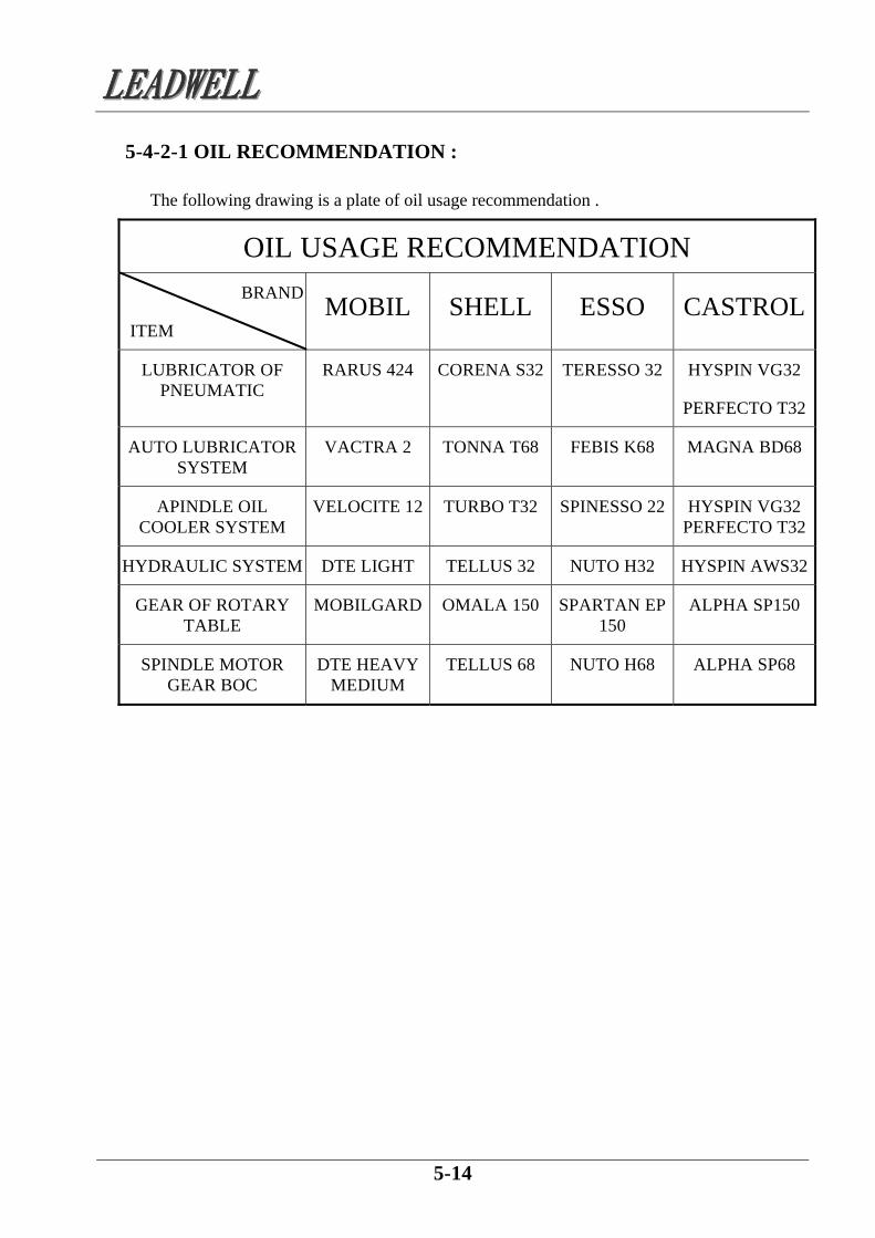
5-4-2-1 OIL RECOMMENDATION :
The following drawing is a plate of oil usage recommendation .
OIL USAGE RECOMMENDATION BRAND
ITEM MOBIL SHELL ESSO CASTROL
LUBRICATOR OF PNEUMATIC
RARUS 424 CORENA S32 TERESSO 32 HYSPIN VG32
PERFECTO T32
AUTO LUBRICATOR SYSTEM
VACTRA 2 TONNA T68 FEBIS K68 MAGNA BD68
APINDLE OIL COOLER SYSTEM
VELOCITE 12 TURBO T32 SPINESSO 22 HYSPIN VG32 PERFECTO T32
HYDRAULIC SYSTEM DTE LIGHT TELLUS 32 NUTO H32 HYSPIN AWS32
GEAR OF ROTARY TABLE
MOBILGARD OMALA 150 SPARTAN EP 150
ALPHA SP150
SPINDLE MOTOR GEAR BOC
DTE HEAVY MEDIUM
TELLUS 68 NUTO H68 ALPHA SP68
LLLEEEAAADDDWWWEEELLLLLL
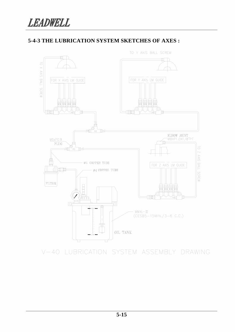
5-15
5-4-3 THE LUBRICATION SYSTEM SKETCHES OF AXES :
LLLEEEAAADDDWWWEEELLLLLL
5-16
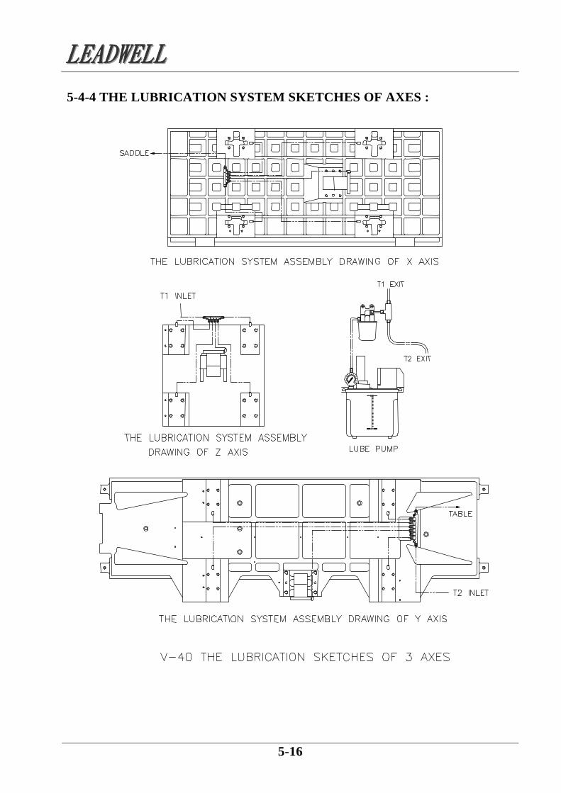
5-4-4 THE LUBRICATION SYSTEM SKETCHES OF AXES :
LLLEEEAAADDDWWWEEELLLLLL
5-17
5-5 HEAT EXCHANGER SYSTEM :
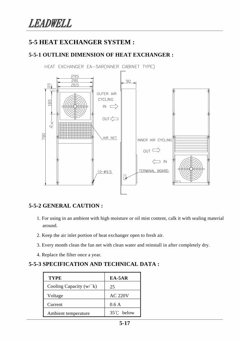
5-5-1 OUTLINE DIMENSION OF HEAT EXCHANGER :
5-5-2 GENERAL CAUTION :
1. For using in an ambient with high moisture or oil mist content, calk it with sealing material around.
2. Keep the air inlet portion of heat exchanger open to fresh air.
3. Every month clean the fan net with clean water and reinstall in after completely dry.
4. Replace the filter once a year.
5-5-3 SPECIFICATION AND TECHNICAL DATA :
TYPE EA-5AR
Cooling Capacity (w/°k) 25
Voltage AC 220V
Current 0.6 A
Ambient temperature 35℃ below

LLLEEEAAADDDWWWEEELLLLLL
5-18
5-5-4 BASIC MAINTENANCE :
1. Check and ensure that hot air exhausted from the heat exchanger every day.
2. If no hot air exhausted, check top and lower fans on heat exchanger if they can rotate normally.
3. If one of them did not operate, check if the wire connection is correct.
4. If wire connected correctly, that means, the motor is out of order and contact with our service person to replace.
5. If both of fans stop to operate, check the circuit breaker if it is short. (CP4)
6. If the circuit breaker is normal condition, check the fans again after resetting.
7. If it still can not operate, please contact our service person to replace.
LLLEEEAAADDDWWWEEELLLLLL
6-1
6 OPERATION:
6-1 MISCELLANEOUS FUNCTION (M FUNCTION/M CODE) : In operating this machine, specify on/off controls on the operation panel such as spindle start/stop, coolant on/off, mirror image, table indexing, tool change, etc.. Within 2 digits the address M. Two or more M codes other than specially approved combination are not allowed in the same block.
6-2 SPECIFYING THE SPINDLE SPEED (S FUNCTION/S CODE) : Specify directly a spindle speed with 4 digits numerical values following the address S. S45 45 rpm S4000 4000 rpm Program example : S500* Specify the spindle speed M03* Spindle start S3500* Changing the speed at runing condition M05* Spindle stop M04* Reverse rotation at 300 rpm NOTE 1 : During spindle rotation, if the S command is given the spindle will run and
change its speed. NOTE 2 : If an axis movement command is specified simultaneously with M03 or M04,
spindle rotation and axis movement will start at the same time. If the axis movement command is specified simultaneously with M05, the spindle will stop after completing an axis movement.
6-3 TOOL NUMBER CODE (T FUNCTION/T CODE) :
Specify within a 2 digits numerical values following the address rang from 0 to 99.
Program example :
M06 T02* Change tool to No.2
NOTE : If only a T command is given, it is for NC memorized no action. However, if T command is specified simultaneously with M06, the tool changing fuction will be performed.
6-4 SPECIFYING THE FEED RATE (F FUNCTION) :
a. With a numerical value of 1 to 5000 following the address F, specify a speed at which the tool moves over a distance between two fixed points by linear or circular interpolation.
LLLEEEAAADDDWWWEEELLLLLL
6-2
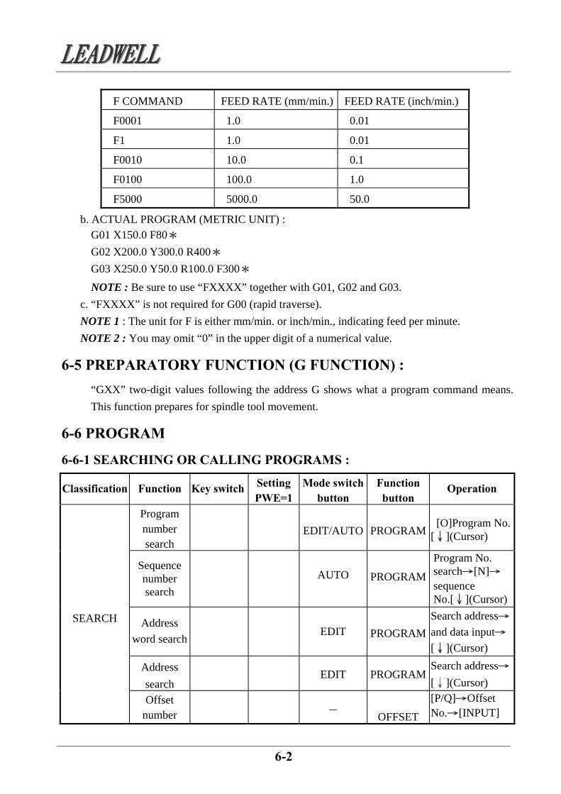
F COMMAND FEED RATE (mm/min.) FEED RATE (inch/min.)
F0001 1.0 0.01
F1 1.0 0.01
F0010 10.0 0.1
F0100 100.0 1.0
F5000 5000.0 50.0
b. ACTUAL PROGRAM (METRIC UNIT) : G01 X150.0 F80* G02 X200.0 Y300.0 R400* G03 X250.0 Y50.0 R100.0 F300* NOTE : Be sure to use “FXXXX” together with G01, G02 and G03.
c. “FXXXX” is not required for G00 (rapid traverse). NOTE 1 : The unit for F is either mm/min. or inch/min., indicating feed per minute. NOTE 2 : You may omit “0” in the upper digit of a numerical value.
6-5 PREPARATORY FUNCTION (G FUNCTION) : “GXX” two-digit values following the address G shows what a program command means. This function prepares for spindle tool movement.
6-6 PROGRAM
6-6-1 SEARCHING OR CALLING PROGRAMS :
Classification Function Key switch Setting PWE=1
Mode switch button
Function button
Operation
Program number search
EDIT/AUTO PROGRAM
[O]Program No. [↓](Cursor)
Sequence number search
AUTO PROGRAM
Program No. search→[N]→sequence No.[↓](Cursor)
SEARCH Address word search
EDIT PROGRAM
Search address→and data input→[↓](Cursor)
Address search
EDIT PROGRAM Search address→[↓](Cursor)
Offset number
- OFFSET
[P/Q]→Offset No.→[INPUT]
LLLEEEAAADDDWWWEEELLLLLL
6-3
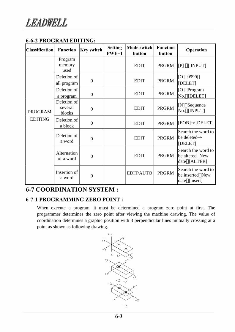
6-6-2 PROGRAM EDITING: Classification Function Key switch Setting
PWE=1Mode switch
button Function button
Operation
Program memory
used
EDIT PRGRM [P] [ INPUT]
Deletion of all program 0
EDIT PRGRM
[O] 9999 [DELET]
Deletion of a program 0
EDIT PRGRM
[O] Program No. [DELET]
PROGRAM
Deletion of several blocks
0
EDIT PRGRM [N] Sequence No. [INPUT]
EDITING Deletion of a block 0
EDIT PRGRM [EOB]→[DELET]
Deletion of
a word 0
EDIT PRGRM Search the word to be deleted→[DELET]
Alternation of a word 0
EDIT PRGRM
Search the word to be altered New date [ALTER]
Insertion of
a word 0
EDIT/AUTO PRGRM Search the word to be inserted New date [insert]
6-7 COORDINATION SYSTEM : 6-7-1 PROGRAMMING ZERO POINT :
When execute a program, it must be determined a program zero point at first. The programmer determines the zero point after viewing the machine drawing. The value of coordination determines a graphic position with 3 perpendicular lines mutually crossing at a point as shown as following drawing.
LLLEEEAAADDDWWWEEELLLLLL
6-4
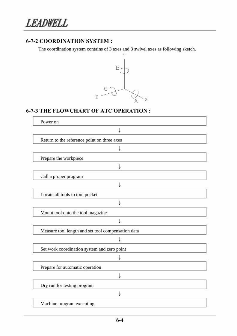
6-7-2 COORDINATION SYSTEM : The coordination system contains of 3 axes and 3 swivel axes as following sketch.
6-7-3 THE FLOWCHART OF ATC OPERATION :
Power on
↓
Return to the reference point on three axes
↓
Prepare the workpiece
↓
Call a proper program
↓
Locate all tools to tool pocket
↓
Mount tool onto the tool magazine
↓
Measure tool length and set tool compensation data
↓
Set work coordination system and zero point
↓
Prepare for automatic operation
↓
Dry run for testing program
↓
Machine program executing
LLLEEEAAADDDWWWEEELLLLLL
6-5
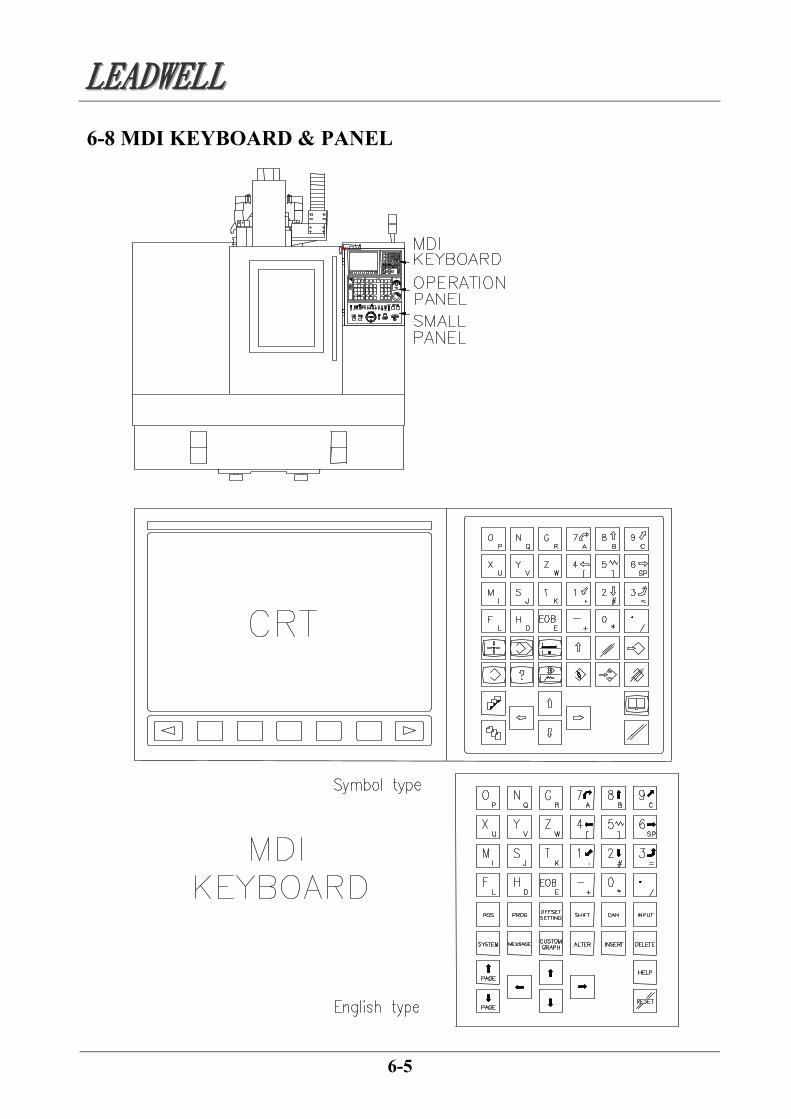
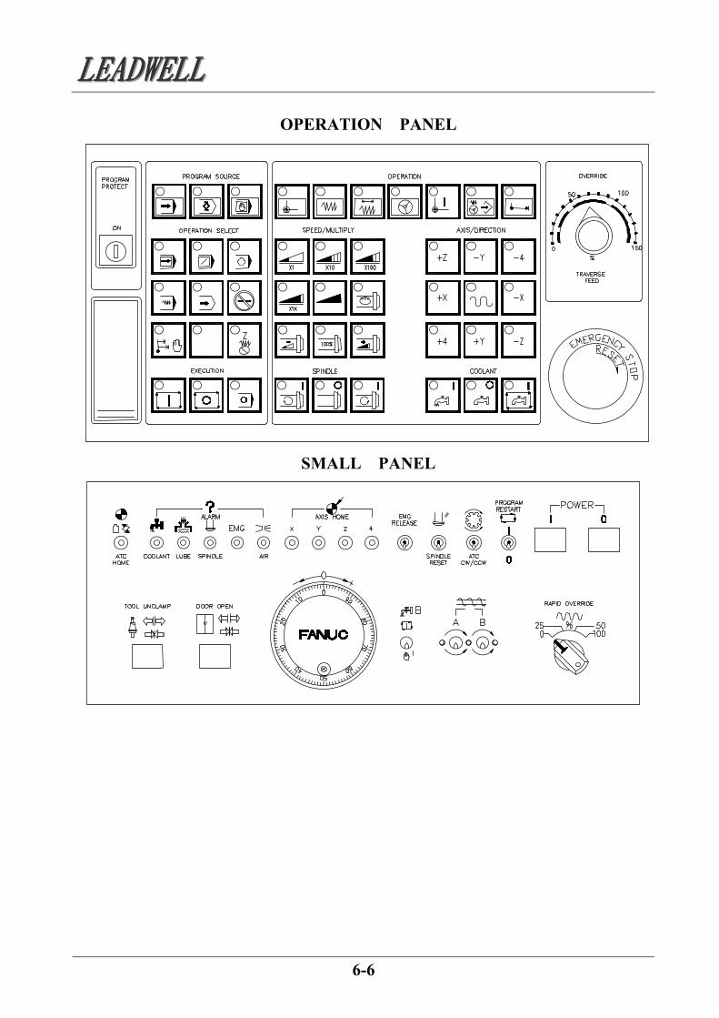
6-8 MDI KEYBOARD & PANEL
LLLEEEAAADDDWWWEEELLLLLL
6-6
OPERATION PANEL
SMALL PANEL

LLLEEEAAADDDWWWEEELLLLLL
6-7
6-9 MDI KEYBOARD FUNCTIONS :
Address or numeric keys used to enter letters and numbers.
Cursor keys used to move cursor to expecting direction.
Page-up and page-down keys used to move screen on the CRT.
Help key used to get help with operations when operator does not know what to do next.
Reset key used to reset the CNC to release alarm or other setting.
Shift key pressed to input the lower right letter on the address/numberic keys.
Cancel key pressed to delete the input of letters or numbers on the key input buffer.
Input key pressed to input any address or numberic key in the key input buffer, then display on the CRT.
LLLEEEAAADDDWWWEEELLLLLL
6-8
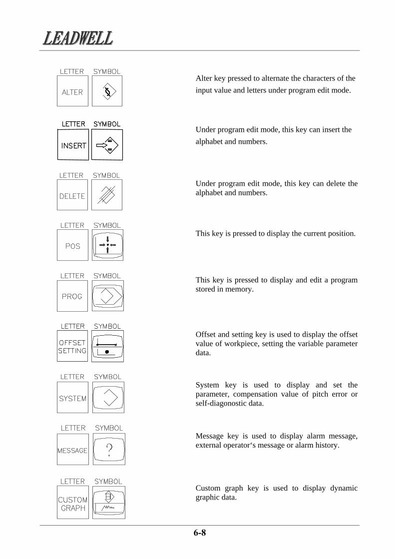
Alter key pressed to alternate the characters of the input value and letters under program edit mode.
Under program edit mode, this key can insert the alphabet and numbers.
Under program edit mode, this key can delete the alphabet and numbers.
This key is pressed to display the current position.
This key is pressed to display and edit a program stored in memory.
Offset and setting key is used to display the offset value of workpiece, setting the variable parameter data.
System key is used to display and set the parameter, compensation value of pitch error or self-diagonostic data.
Message key is used to display alarm message, external operator‘s message or alarm history.
Custom graph key is used to display dynamic graphic data.
LLLEEEAAADDDWWWEEELLLLLL
6-9
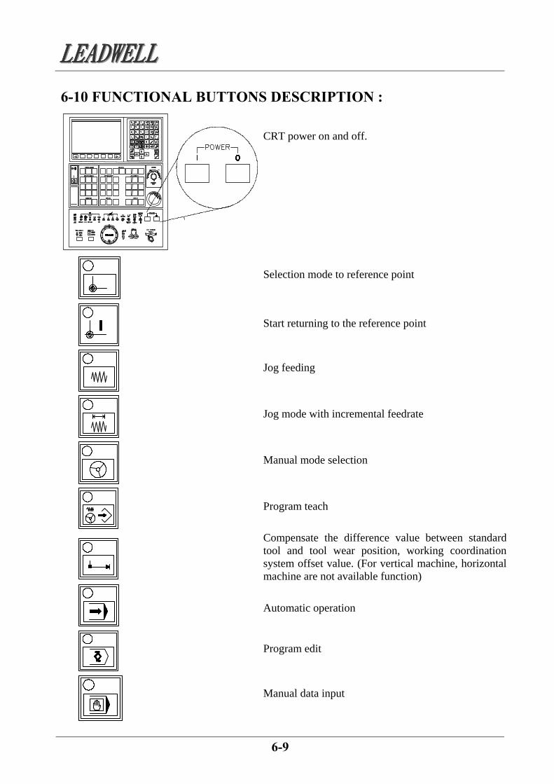
6-10 FUNCTIONAL BUTTONS DESCRIPTION :
CRT power on and off.
Selection mode to reference point
Start returning to the reference point
Jog feeding
Jog mode with incremental feedrate
Manual mode selection
Program teach
Compensate the difference value between standard tool and tool wear position, working coordination system offset value. (For vertical machine, horizontal machine are not available function)
Automatic operation
Program edit
Manual data input
LLLEEEAAADDDWWWEEELLLLLL
6-10
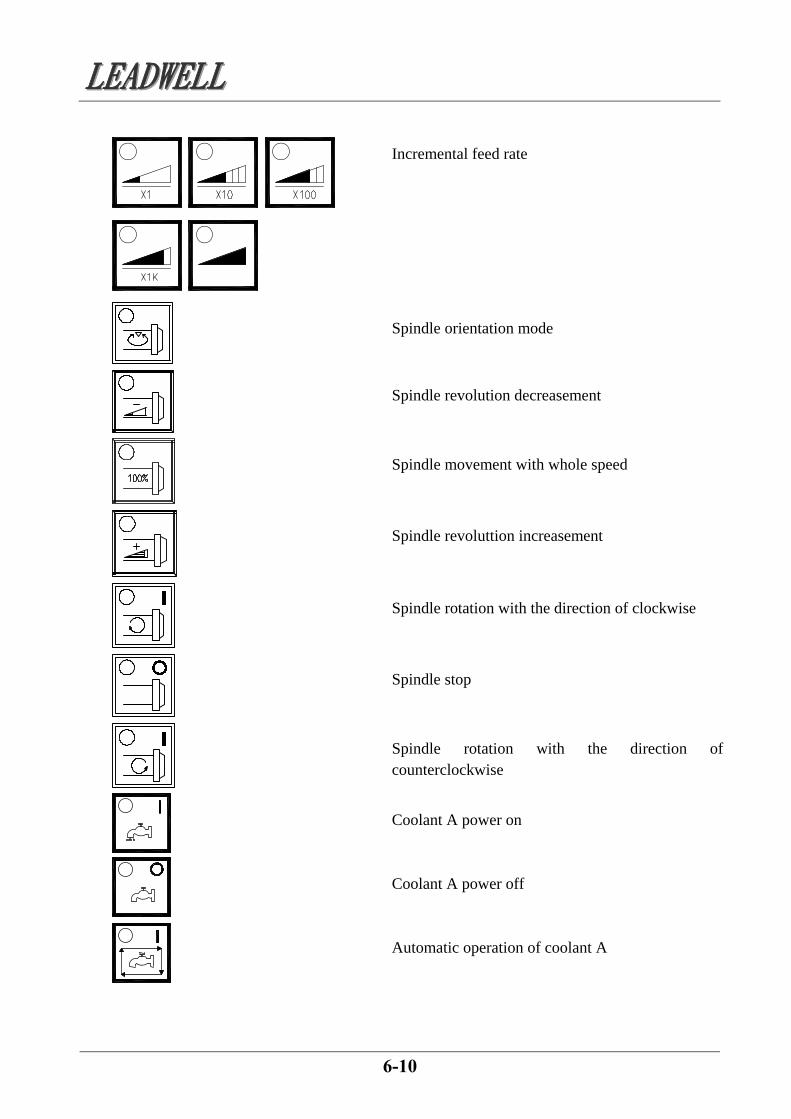
Incremental feed rate
Spindle orientation mode
Spindle revolution decreasement
Spindle movement with whole speed
Spindle revoluttion increasement
Spindle rotation with the direction of clockwise
Spindle stop
Spindle rotation with the direction of counterclockwise
Coolant A power on
Coolant A power off
Automatic operation of coolant A
LLLEEEAAADDDWWWEEELLLLLL
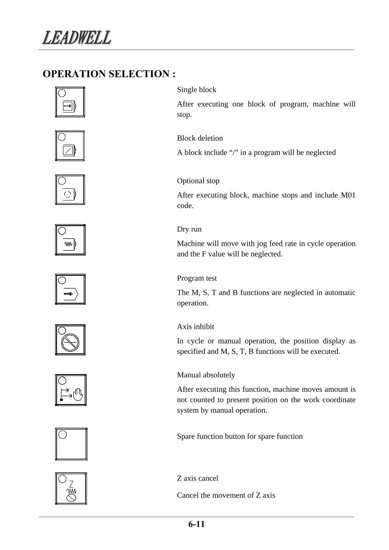
OPERATION SELECTION :
Single block
After executing one block of program, machine will stop.
Block deletion
A block include “/” in a program will be neglected
Optional stop
After executing block, machine stops and include M01 code.
Dry run
Machine will move with jog feed rate in cycle operation and the F value will be neglected.
Program test
The M, S, T and B functions are neglected in automaticoperation.
Axis inhibit
In cycle or manual operation, the position display as specified and M, S, T, B functions will be executed.
Manual absolutely
After executing this function, machine moves amount is not counted to present position on the work coordinate system by manual operation.
Spare function button for spare function
Z axis cancel
Cancel the movement of Z axis
6-11
LLLEEEAAADDDWWWEEELLLLLL
6-12
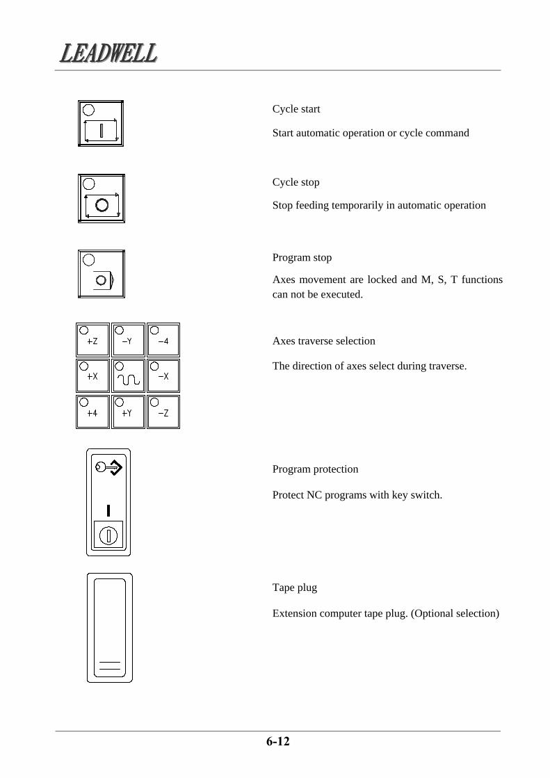
Cycle start
Start automatic operation or cycle command
Cycle stop
Stop feeding temporarily in automatic operation
Program stop
Axes movement are locked and M, S, T functions can not be executed.
Axes traverse selection
The direction of axes select during traverse.
Program protection
Protect NC programs with key switch.
Tape plug
Extension computer tape plug. (Optional selection)
LLLEEEAAADDDWWWEEELLLLLL
6-13
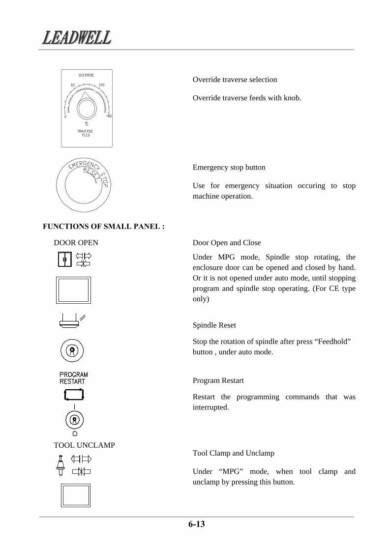
Override traverse selection
Override traverse feeds with knob.
Emergency stop button
Use for emergency situation occuring to stop machine operation.
FUNCTIONS OF SMALL PANEL :
DOOR OPEN
Door Open and Close
Under MPG mode, Spindle stop rotating, the enclosure door can be opened and closed by hand. Or it is not opened under auto mode, until stopping program and spindle stop operating. (For CE type only)
Spindle Reset
Stop the rotation of spindle after press “Feedhold” button , under auto mode.
Program Restart
Restart the programming commands that was interrupted.
TOOL UNCLAMP
Tool Clamp and Unclamp
Under “MPG” mode, when tool clamp and unclamp by pressing this button.
LLLEEEAAADDDWWWEEELLLLLL
6-14
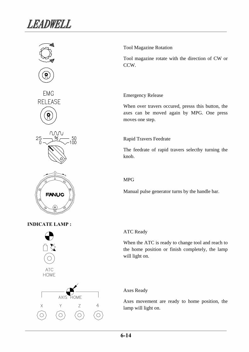
Tool Magazine Rotation
Tool magazine rotate with the direction of CW or CCW.
Emergency Release
When over travers occured, presss this button, the axes can be moved again by MPG. One press moves one step.
Rapid Travers Feedrate
The feedrate of rapid travers selectby turning the knob.
MPG
Manual pulse generator turns by the handle bar.
INDICATE LAMP :
ATC Ready
When the ATC is ready to change tool and reach to the home position or finish completely, the lamp will light on.
Axes Ready
Axes movement are ready to home position, the lamp will light on.
LLLEEEAAADDDWWWEEELLLLLL
6-15
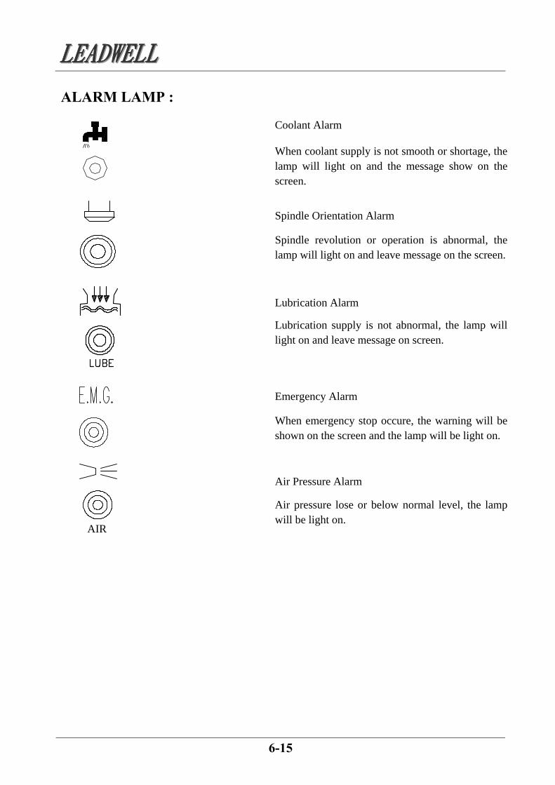
ALARM LAMP :
Coolant Alarm
When coolant supply is not smooth or shortage, the lamp will light on and the message show on the screen.
Spindle Orientation Alarm
Spindle revolution or operation is abnormal, the lamp will light on and leave message on the screen.
Lubrication Alarm
Lubrication supply is not abnormal, the lamp will light on and leave message on screen.
Emergency Alarm
When emergency stop occure, the warning will be shown on the screen and the lamp will be light on.
AIR
Air Pressure Alarm
Air pressure lose or below normal level, the lamp will be light on.
LLLEEEAAADDDWWWEEELLLLLL
6-16
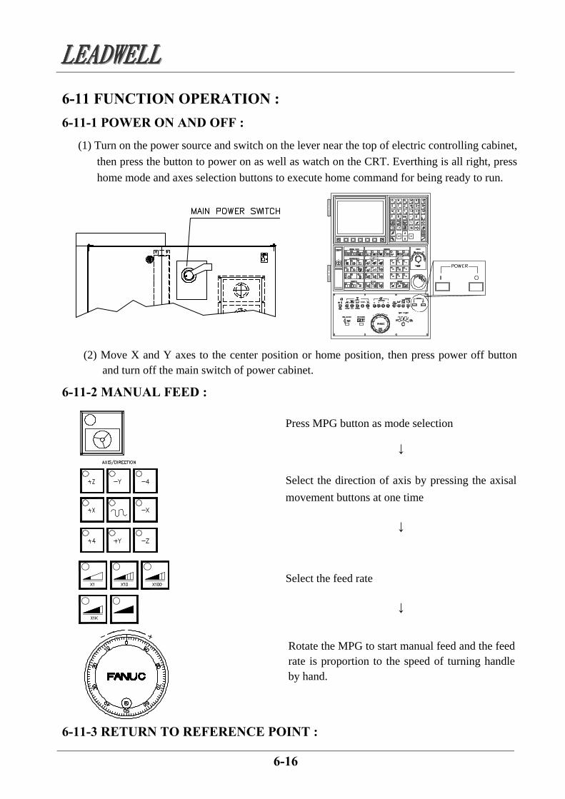
6-11 FUNCTION OPERATION : 6-11-1 POWER ON AND OFF :
(1) Turn on the power source and switch on the lever near the top of electric controlling cabinet, then press the button to power on as well as watch on the CRT. Everthing is all right, press home mode and axes selection buttons to execute home command for being ready to run.
(2) Move X and Y axes to the center position or home position, then press power off button
and turn off the main switch of power cabinet.
6-11-2 MANUAL FEED :
Press MPG button as mode selection
↓
Select the direction of axis by pressing the axisal movement buttons at one time
↓
Select the feed rate
↓
Rotate the MPG to start manual feed and the feed rate is proportion to the speed of turning handle by hand.
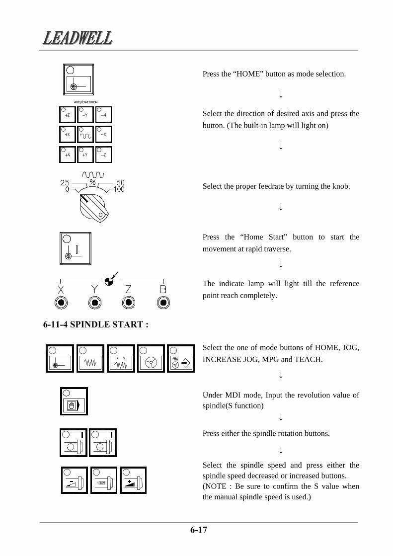
6-11-3 RETURN TO REFERENCE POINT :
LLLEEEAAADDDWWWEEELLLLLL
6-17
Press the “HOME” button as mode selection.
↓
Select the direction of desired axis and press the button. (The built-in lamp will light on)
↓
Select the proper feedrate by turning the knob.
↓
Press the “Home Start” button to start the movement at rapid traverse.
↓
The indicate lamp will light till the reference point reach completely.
6-11-4 SPINDLE START :
Select the one of mode buttons of HOME, JOG, INCREASE JOG, MPG and TEACH.
↓
Under MDI mode, Input the revolution value of spindle(S function)
↓
Press either the spindle rotation buttons.
↓
Select the spindle speed and press either the spindle speed decreased or increased buttons. (NOTE : Be sure to confirm the S value when the manual spindle speed is used.)
LLLEEEAAADDDWWWEEELLLLLL
6-18
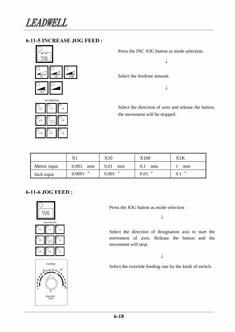
6-11-5 INCREASE JOG FEED :
Press the INC JOG button as mode selection.
↓
Select the feedrate amount.
↓
Select the direction of axes and release the button, the movement will be stopped.
X1 X10 X100 X1K
Metric input 0.001 mm 0.01 mm 0.1 mm 1 mm
Inch input 0.0001 〞 0.001 〞 0.01 〞 0.1 〞
6-11-6 JOG FEED :
Press the JOG button as mode selection
↓
Select the direction of designation axis to start the movement of axes. Release the button and the movement will stop.
↓
Select the override feeding rate by the knob of switch.
LLLEEEAAADDDWWWEEELLLLLL
6-19
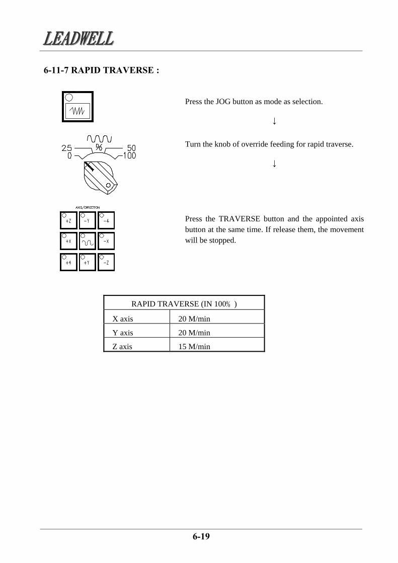
6-11-7 RAPID TRAVERSE :
Press the JOG button as mode as selection.
↓
Turn the knob of override feeding for rapid traverse.
↓
Press the TRAVERSE button and the appointed axis button at the same time. If release them, the movement will be stopped.
RAPID TRAVERSE (IN 100﹪)
X axis 20 M/min
Y axis 20 M/min
Z axis 15 M/min
LLLEEEAAADDDWWWEEELLLLLL
7-1
7 CLEAN AND MAINTENANCE CAUTION : 1. Shut off the power before doing any maintenance or cleaning job and obey the
instruction or you might be hurt.
2. Any clean or maintenance concerned with removing must be careful and only well-trained personnel can do it.
7-1 DAILY MAINTENANCE :
7-1-1 BEFORE POWER ON :
a. Inspect if the power cable and external cable are normally connected and the voltage capacity is matched as machine required.
b. Check if there is oil or coolant leakage on the hydraulic or coolant pipes.
c. Check if there are enough oil for the hydraulic unit, lubrication unit and coolant unit.
d. Check if the pressure gauges of hydraulic unit and pneumatic unit were indicated to zero position.
e. Check if the auto tool changer unit is at the normal position.
7-1-2 AFTER POWER ON :
a. Check if there is alarm message after NC power on.
b. NC should be ready to execute the program.
c. All the running components should be run at normal condition without noise.
d. The pressure gauge for pneumatic system should be at 6 kg/cm2.
e. Auto lubricator should be actuated to pump oil with flow setting to 3-6 c.c./cycle.
f. The lubricant should flow out to the slideways.
g. The wipers on the telescopic covers should be cleaned from the chips.
h. Test tool changing unit and make sure the unit can work smoothly.
7-1-3 AFTER FINISHING DAILY WORK :
a. Inspect the oil level of auto lubricator tank to refill up, if it is necessary and is consumed.
b. If there is water or dirt in the tank, relieve and change fresh oil.
LLLEEEAAADDDWWWEEELLLLLL
7-2
c. Check the level of coolant to refill up and flush the coolant pump through with clean water if there is impurities after use.
d. Clean the chips on the chip tank, conveyor, tool tip and tool magazine.
e. Remove and centralize the chips on the chip bucket out side of the shop.
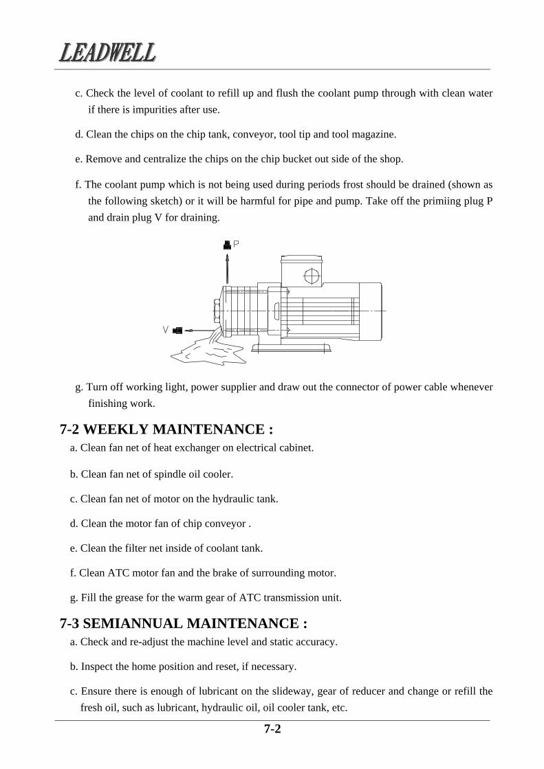
f. The coolant pump which is not being used during periods frost should be drained (shown as the following sketch) or it will be harmful for pipe and pump. Take off the primiing plug P and drain plug V for draining.
g. Turn off working light, power supplier and draw out the connector of power cable whenever
finishing work.
7-2 WEEKLY MAINTENANCE : a. Clean fan net of heat exchanger on electrical cabinet.
b. Clean fan net of spindle oil cooler.
c. Clean fan net of motor on the hydraulic tank.
d. Clean the motor fan of chip conveyor .
e. Clean the filter net inside of coolant tank.
f. Clean ATC motor fan and the brake of surrounding motor.
g. Fill the grease for the warm gear of ATC transmission unit.
7-3 SEMIANNUAL MAINTENANCE : a. Check and re-adjust the machine level and static accuracy.
b. Inspect the home position and reset, if necessary.
c. Ensure there is enough of lubricant on the slideway, gear of reducer and change or refill the fresh oil, such as lubricant, hydraulic oil, oil cooler tank, etc.

LLLEEEAAADDDWWWEEELLLLLL
7-3
d. Inspect the backlash of ball screw on three axes.
e. Inspect the repeatitive accuracy and geometric accuracy of machine.
f. Replace the fan net of heat exchanger on electrical cabinet.
g. Replace the element of filter on hydraulic tank or other accessary parts.
h. Clean the electrical motor outside and turn off the power at first.
i. Before cleaning the chip or dirt on the conduction block of sensor and magnetic switch, turn off the power.
j. Check the smooth function of all limit switches for axes and clean the dirt or re-adjust the position, if necessary.
7-4 ANNUAL MAINTENANCE :
a. Follow the same procedures as mentioned above semiannual maintenance.
b. Replace the hydraulic oil and oil filter according to the oil recommandation.
c. Replace the filter for auto lubricator and clean the lubrication tank, coolant tank.
d. Do not pour out the wasting oil or coolant liquid casually. It‘d better remain in oil bucket periodically and send to the authorities concerned of shop to do with it.
e. Check and correct the geometric accuracy of machine.
7-5 ENVIRONMENTAL CLAIMS :
God creates this world and gives humanbeing the rights to rule over the earth. Leadwell, a part of this family shall have responsibility and duty to keep the earth away from damage or pollution during producting. We all obey the laws and regulations through our policy of quality control management and concept of environmental protection issue. We have been devoted ourselves on the environmental management system no matter at work or in life. It is our final destination that to make a sustainable development business and to provid a pure clean environment to the generations.
7-6 OUR GOAL :
1. RESOURCES RECOVERY : Not only check devices periodically and save the resources but reuse the recyclable resources and develop new less-polluted resources.
2. REDUCING WASTE : Specify and recycle the waste and reduce the quantity of waste.
LLLEEEAAADDDWWWEEELLLLLL
7-4
3. WATER CONTROL : Inspec the water, wastewater drained off to the sewage treatment plant through our sanitary sewer.
4. AIR CONTROL : Reduce air pollutants, obey the laws about emissions standard of air pollution. remain a high quaility and all devices are in good condition.
7-7 WASTE TREATMENT :
1. DURING OPERATION :
a. Waste Oil : There is any leakage of oil or liquid during operating machine, stop and check machine. Meanwhile report to your supervisor or manager to solve. The waste oil, solution or liquid must pour into the stored bucket at plant or follow the rules and procedures of waste treatment of your own control measures. It can not be poured out at random and not be allowed draining down through sewer.
b. Cutting Chips : Some of the cutting chips are able to recycle, after machining, the chips must seperate and restore by material. It is must be placed and treat according to the environmental regulations of local plant.
c. Toxic gas : Check the concentration of exhaust emissions and the emission equipments. Control the value to standard request every cyclic inspection.
2. AFTER OPERATION :
Waste Machine : When machine is out of order can not be fixed, do not throw away directly and sepreat the machine to pieces by material. Some of the material can be recycled such as casting iron, steel, metal, etc.. Some of them can not be reused such as cables, electrical parts, motors, PCB board, etc.. Store the same parts according to their material to do with local dealer or the procedures of waste treatment on your own.
LLLEEEAAADDDWWWEEELLLLLL
8-MGCODE A-1-1
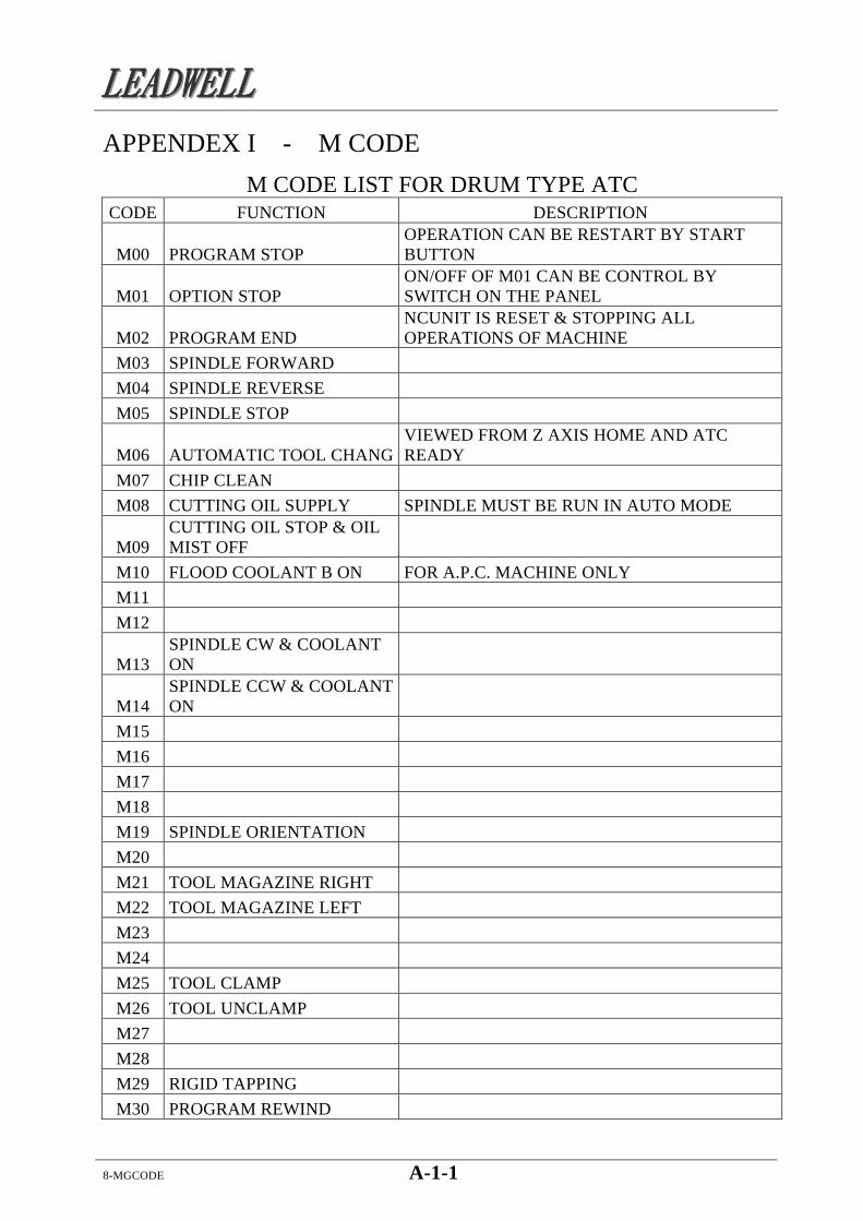
APPENDEX I - M CODE M CODE LIST FOR DRUM TYPE ATC
CODE FUNCTION DESCRIPTION
M00 PROGRAM STOP OPERATION CAN BE RESTART BY START BUTTON
M01 OPTION STOP ON/OFF OF M01 CAN BE CONTROL BY SWITCH ON THE PANEL
M02 PROGRAM END NCUNIT IS RESET & STOPPING ALL OPERATIONS OF MACHINE
M03 SPINDLE FORWARD M04 SPINDLE REVERSE M05 SPINDLE STOP
M06 AUTOMATIC TOOL CHANGVIEWED FROM Z AXIS HOME AND ATC READY
M07 CHIP CLEAN M08 CUTTING OIL SUPPLY SPINDLE MUST BE RUN IN AUTO MODE
M09 CUTTING OIL STOP & OIL MIST OFF
M10 FLOOD COOLANT B ON FOR A.P.C. MACHINE ONLY M11 M12
M13 SPINDLE CW & COOLANT ON
M14 SPINDLE CCW & COOLANT ON
M15 M16 M17 M18 M19 SPINDLE ORIENTATION M20 M21 TOOL MAGAZINE RIGHT M22 TOOL MAGAZINE LEFT M23 M24 M25 TOOL CLAMP M26 TOOL UNCLAMP M27 M28 M29 RIGID TAPPING M30 PROGRAM REWIND

LLLEEEAAADDDWWWEEELLLLLL
8-MGCODE A-1-2
M CODE LIST FOR DRUM TYPE ATC
CODE FUNCTION DESCRIPTION M31 M32 M33 M34 M35 M36 M37 M38 M39 M40 4 AXIS CLAMP FOR 4 AXIS WITH 4TH AXIS SPARE FUNCTIONM41 4 AXIS UNCLAMP FOR 4 AXIS WITH 4TH AXIS SPARE FUNCTIONM42 INDEXER CYCLE FOR 4 AXIS WITH INDEX FUNCTION M43 M44 M45 CHIP CONVEYOR ON M46 CHIP CONVEYOR OFF M47 M48 M49 M50 M51 M52 M53 M54 M55 M56 M57 M58 M59 M60 M61 MIRROR IMAGE X OFF M62 MIRROR IMAGE Y OFF M63 M64 MIRROR IMAGE 4 OFF M65 M66 DURING OF TOOL CHANG M67 CANCAL M66
LLLEEEAAADDDWWWEEELLLLLL
8-MGCODE A-1-3
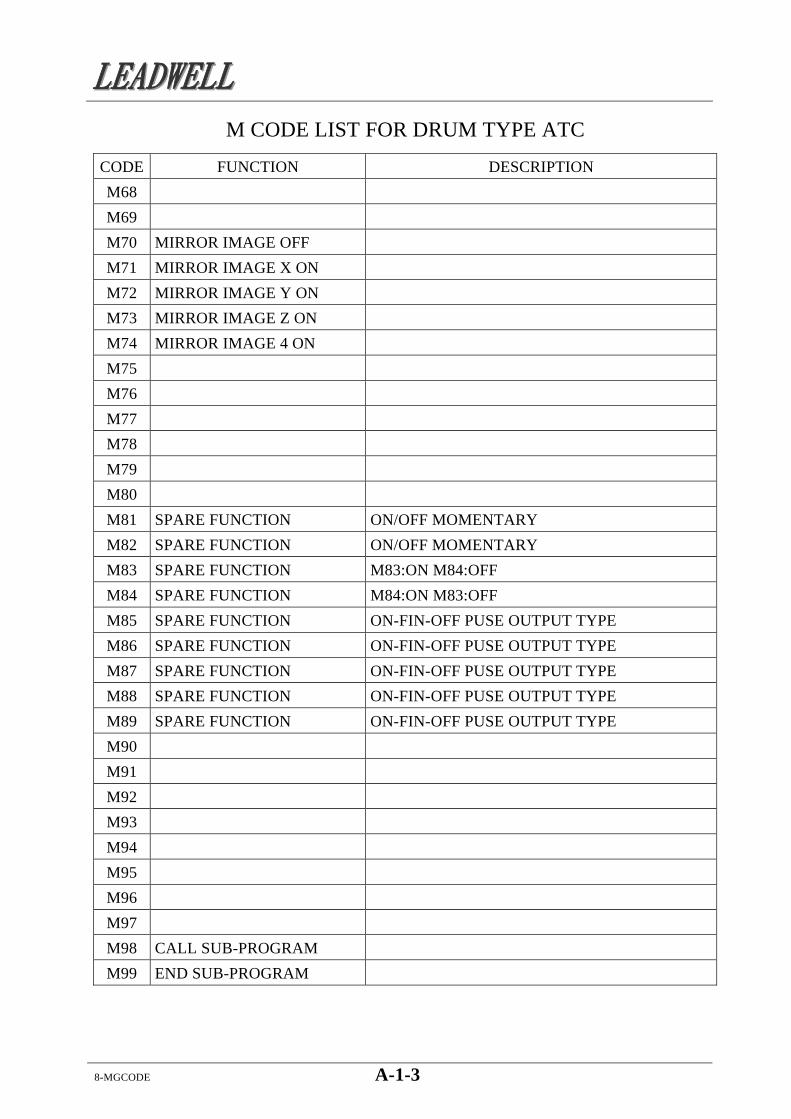
M CODE LIST FOR DRUM TYPE ATC
CODE FUNCTION DESCRIPTION M68 M69 M70 MIRROR IMAGE OFF M71 MIRROR IMAGE X ON M72 MIRROR IMAGE Y ON M73 MIRROR IMAGE Z ON M74 MIRROR IMAGE 4 ON M75 M76 M77 M78 M79 M80 M81 SPARE FUNCTION ON/OFF MOMENTARY M82 SPARE FUNCTION ON/OFF MOMENTARY M83 SPARE FUNCTION M83:ON M84:OFF M84 SPARE FUNCTION M84:ON M83:OFF M85 SPARE FUNCTION ON-FIN-OFF PUSE OUTPUT TYPE M86 SPARE FUNCTION ON-FIN-OFF PUSE OUTPUT TYPE M87 SPARE FUNCTION ON-FIN-OFF PUSE OUTPUT TYPE M88 SPARE FUNCTION ON-FIN-OFF PUSE OUTPUT TYPE M89 SPARE FUNCTION ON-FIN-OFF PUSE OUTPUT TYPE M90 M91 M92 M93 M94 M95 M96 M97 M98 CALL SUB-PROGRAM M99 END SUB-PROGRAM
LLLEEEAAADDDWWWEEELLLLLL
8-MGCODE A-1-4
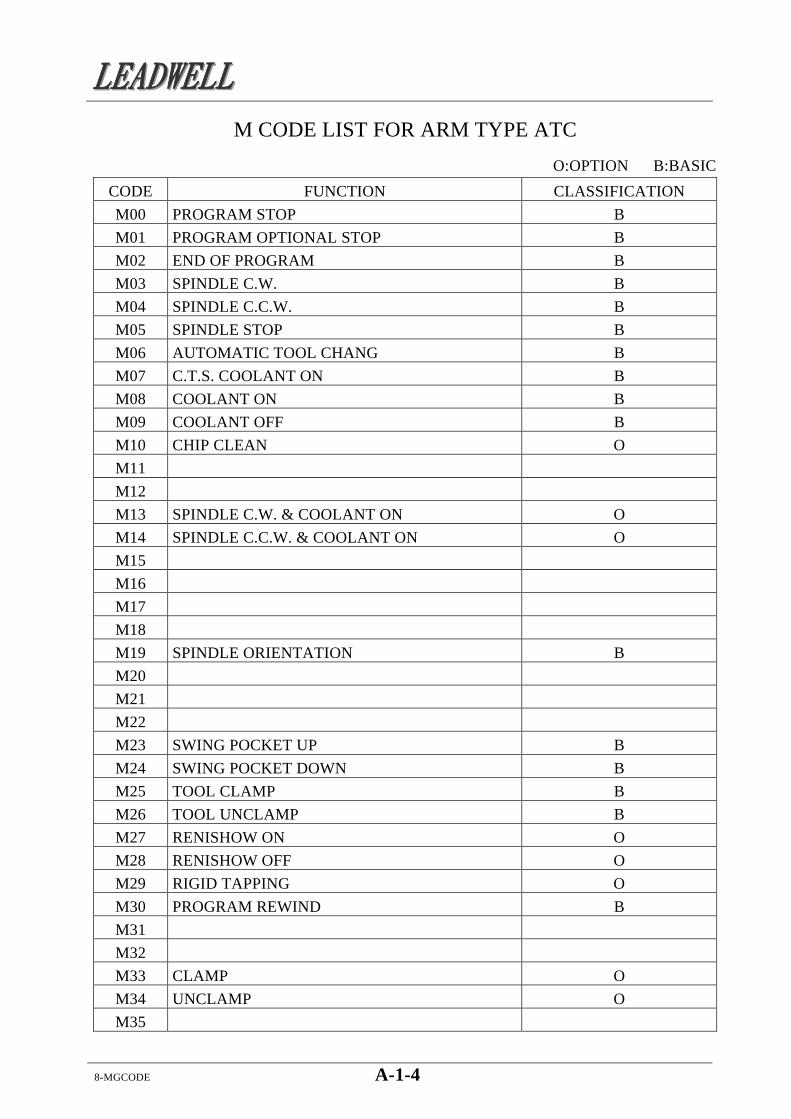
M CODE LIST FOR ARM TYPE ATC O:OPTION B:BASIC
CODE FUNCTION CLASSIFICATION M00 PROGRAM STOP B M01 PROGRAM OPTIONAL STOP B M02 END OF PROGRAM B M03 SPINDLE C.W. B M04 SPINDLE C.C.W. B M05 SPINDLE STOP B M06 AUTOMATIC TOOL CHANG B M07 C.T.S. COOLANT ON B M08 COOLANT ON B M09 COOLANT OFF B M10 CHIP CLEAN O M11 M12 M13 SPINDLE C.W. & COOLANT ON O M14 SPINDLE C.C.W. & COOLANT ON O M15 M16 M17 M18 M19 SPINDLE ORIENTATION B M20 M21 M22 M23 SWING POCKET UP B M24 SWING POCKET DOWN B M25 TOOL CLAMP B M26 TOOL UNCLAMP B M27 RENISHOW ON O M28 RENISHOW OFF O M29 RIGID TAPPING O M30 PROGRAM REWIND B M31 M32 M33 CLAMP O M34 UNCLAMP O M35
LLLEEEAAADDDWWWEEELLLLLL
8-MGCODE A-1-5
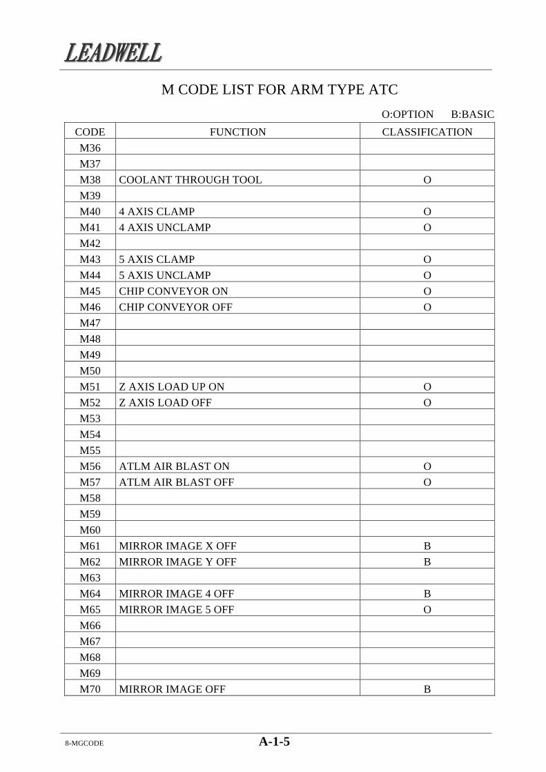
M CODE LIST FOR ARM TYPE ATC O:OPTION B:BASIC
CODE FUNCTION CLASSIFICATION M36 M37 M38 COOLANT THROUGH TOOL O M39 M40 4 AXIS CLAMP O M41 4 AXIS UNCLAMP O M42 M43 5 AXIS CLAMP O M44 5 AXIS UNCLAMP O M45 CHIP CONVEYOR ON O M46 CHIP CONVEYOR OFF O M47 M48 M49 M50 M51 Z AXIS LOAD UP ON O M52 Z AXIS LOAD OFF O M53 M54 M55 M56 ATLM AIR BLAST ON O M57 ATLM AIR BLAST OFF O M58 M59 M60 M61 MIRROR IMAGE X OFF B M62 MIRROR IMAGE Y OFF B M63 M64 MIRROR IMAGE 4 OFF B M65 MIRROR IMAGE 5 OFF O M66 M67 M68 M69 M70 MIRROR IMAGE OFF B

LLLEEEAAADDDWWWEEELLLLLL
8-MGCODE A-1-6
M CODE LIST FOR ARM TYPE ATC O:OPTION B:BASIC
CODE FUNCTION CLASSIFICATION M71 MIRROR IMAGE X ON B M72 MIRROR IMAGE Y ON B M73 M74 MIRROR IMAGE 4 ON B M75 MIRROR IMAGE 5 ON O M76 M77 SPINDLE LOAD UP ON O M78 SPINDLE LOAD DELECT OFF O M79 SPINDLE LOAD DOWN ON O M80 M81 ON/OFF MOMENTARY O M82 ON/OFF MOMENTARY O M83 M83:ON M84:OFF O M84 M84:ON M83:OFF O M85 ON—FIN--OFF O M86 ON—FIN--OFF O M87 ON—FIN--OFF O M88 M89 M90 M91 M92 M93 M94 M95 PART COUNTER B M96 M97 M98 CALLING OF SUB-PROGRAM B M99 MAIN PROGRAM RETURN B
LLLEEEAAADDDWWWEEELLLLLL
8-MGCODE A-1-7
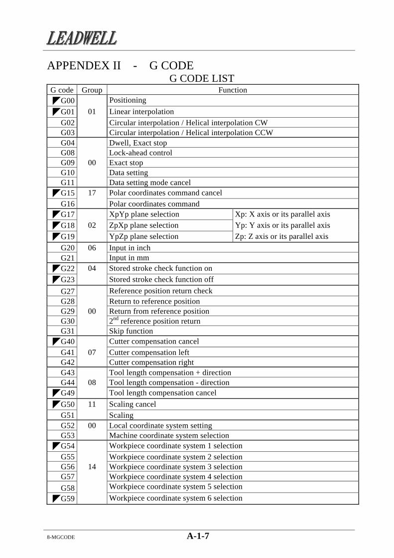
APPENDEX II - G CODE G CODE LIST
G code Group Function ◤G00 Positioning ◤G01 01 Linear interpolation
G02 Circular interpolation / Helical interpolation CW G03 Circular interpolation / Helical interpolation CCW G04 Dwell, Exact stop G08 Lock-ahead control G09 00 Exact stop G10 Data setting G11 Data setting mode cancel
◤G15 17 Polar coordinates command cancel G16 Polar coordinates command
◤G17 XpYp plane selection Xp: X axis or its parallel axis ◤G18 02 ZpXp plane selection Yp: Y axis or its parallel axis ◤G19 YpZp plane selection Zp: Z axis or its parallel axis
G20 06 Input in inch G21 Input in mm
◤G22 04 Stored stroke check function on ◤G23 Stored stroke check function off
G27 Reference position return check G28 Return to reference position G29 00 Return from reference position G30 2nd reference position return G31 Skip function
◤G40 Cutter compensation cancel G41 07 Cutter compensation left G42 Cutter compensation right G43 Tool length compensation + direction G44 08 Tool length compensation - direction
◤G49 Tool length compensation cancel ◤G50 11 Scaling cancel
G51 Scaling G52 00 Local coordinate system setting G53 Machine coordinate system selection
◤G54 Workpiece coordinate system 1 selection G55 Workpiece coordinate system 2 selection G56 14 Workpiece coordinate system 3 selection G57 Workpiece coordinate system 4 selection G58 Workpiece coordinate system 5 selection
◤G59 Workpiece coordinate system 6 selection
LLLEEEAAADDDWWWEEELLLLLL
8-MGCODE A-1-8
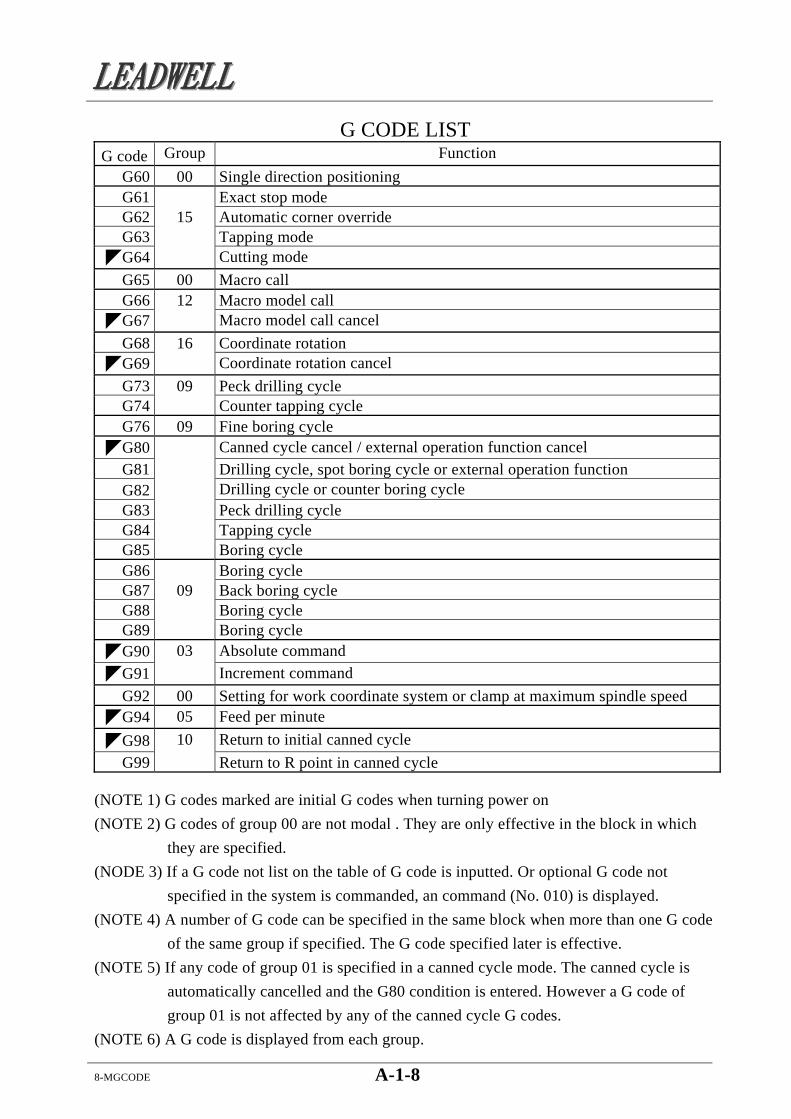
G CODE LIST G code Group Function
G60 00 Single direction positioning G61 Exact stop mode G62 15 Automatic corner override G63 Tapping mode
◤G64 Cutting mode G65 00 Macro call G66 12 Macro model call
◤G67 Macro model call cancel G68 16 Coordinate rotation
◤G69 Coordinate rotation cancel G73 09 Peck drilling cycle G74 Counter tapping cycle G76 09 Fine boring cycle
◤G80 Canned cycle cancel / external operation function cancel G81 Drilling cycle, spot boring cycle or external operation function G82 Drilling cycle or counter boring cycle G83 Peck drilling cycle G84 Tapping cycle G85 Boring cycle G86 Boring cycle G87 09 Back boring cycle G88 Boring cycle G89 Boring cycle
◤G90 03 Absolute command ◤G91 Increment command
G92 00 Setting for work coordinate system or clamp at maximum spindle speed ◤G94 05 Feed per minute ◤G98 10 Return to initial canned cycle
G99 Return to R point in canned cycle
(NOTE 1) G codes marked are initial G codes when turning power on (NOTE 2) G codes of group 00 are not modal . They are only effective in the block in which
they are specified. (NODE 3) If a G code not list on the table of G code is inputted. Or optional G code not
specified in the system is commanded, an command (No. 010) is displayed. (NOTE 4) A number of G code can be specified in the same block when more than one G code
of the same group if specified. The G code specified later is effective. (NOTE 5) If any code of group 01 is specified in a canned cycle mode. The canned cycle is
automatically cancelled and the G80 condition is entered. However a G code of group 01 is not affected by any of the canned cycle G codes.
(NOTE 6) A G code is displayed from each group.

����APPENDIX����
01 1
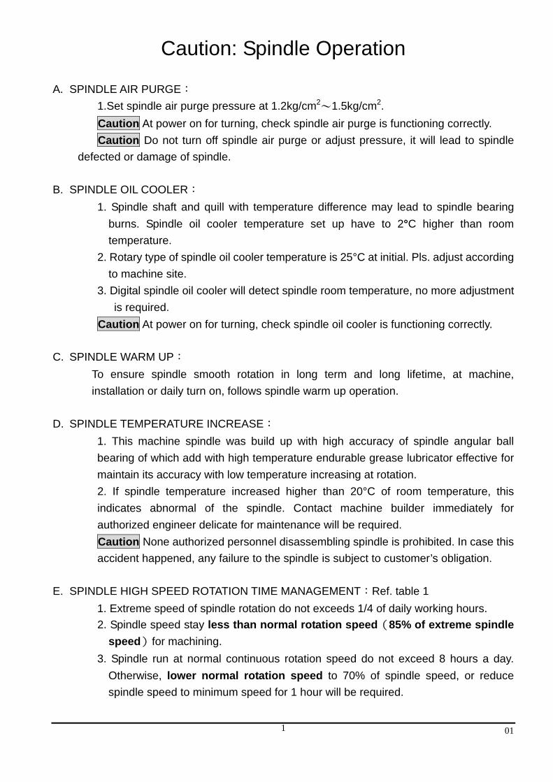
Caution: Spindle Operation A. SPINDLE AIR PURGE:
1.Set spindle air purge pressure at 1.2kg/cm2~1.5kg/cm2. Caution At power on for turning, check spindle air purge is functioning correctly. Caution Do not turn off spindle air purge or adjust pressure, it will lead to spindle
defected or damage of spindle.
B. SPINDLE OIL COOLER: 1. Spindle shaft and quill with temperature difference may lead to spindle bearing
burns. Spindle oil cooler temperature set up have to 2°C higher than room temperature.
2. Rotary type of spindle oil cooler temperature is 25°C at initial. Pls. adjust according to machine site.
3. Digital spindle oil cooler will detect spindle room temperature, no more adjustment is required.
Caution At power on for turning, check spindle oil cooler is functioning correctly.
C. SPINDLE WARM UP: To ensure spindle smooth rotation in long term and long lifetime, at machine, installation or daily turn on, follows spindle warm up operation.
D. SPINDLE TEMPERATURE INCREASE: 1. This machine spindle was build up with high accuracy of spindle angular ball bearing of which add with high temperature endurable grease lubricator effective for maintain its accuracy with low temperature increasing at rotation. 2. If spindle temperature increased higher than 20°C of room temperature, this indicates abnormal of the spindle. Contact machine builder immediately for authorized engineer delicate for maintenance will be required. Caution None authorized personnel disassembling spindle is prohibited. In case this accident happened, any failure to the spindle is subject to customer’s obligation.
E. SPINDLE HIGH SPEED ROTATION TIME MANAGEMENT:Ref. table 1
1. Extreme speed of spindle rotation do not exceeds 1/4 of daily working hours. 2. Spindle speed stay less than normal rotation speed(85% of extreme spindle
speed)for machining. 3. Spindle run at normal continuous rotation speed do not exceed 8 hours a day.
Otherwise, lower normal rotation speed to 70% of spindle speed, or reduce spindle speed to minimum speed for 1 hour will be required.

01 2
4. Spindle speed less than minimum speed is not allowed. Table 1 Spindle specification
Extreme speed of Spindle rotation
Normal spindle rotation speed at
85% of Spindle peak
Minimum speed
8000rpm 8000rpm 7000rpm - 10000rpm 10000rpm 8500rpm 3000rpm 12000rpm 12000rpm 10000rpm 5000rpm 15000rpm 15000rpm 12000rpm 6000rpm
F. SPINDLE GUARANTEE: 1. Spindle of normal operation, general spare parts will be guaranteed for 1 year.
2. Spindle bearing guaranteed for 2000hrs of rotation.