lcm assembly techniques - mouser electronics ... keyboards – notebook keyboards – mice –...
TRANSCRIPT
Desktop Keyboards – Notebook Keyboards – Mice – Embedded Pointing Devices Touch Panels – Keyboard Video Mouse Switches Please note that this information may be subject to change Created September 2002 Title :-Assembly Techniques Issue 4.0
With our products wealways look to the future.
www.fceu.fujitsu.com LCM Assembly Techniques...
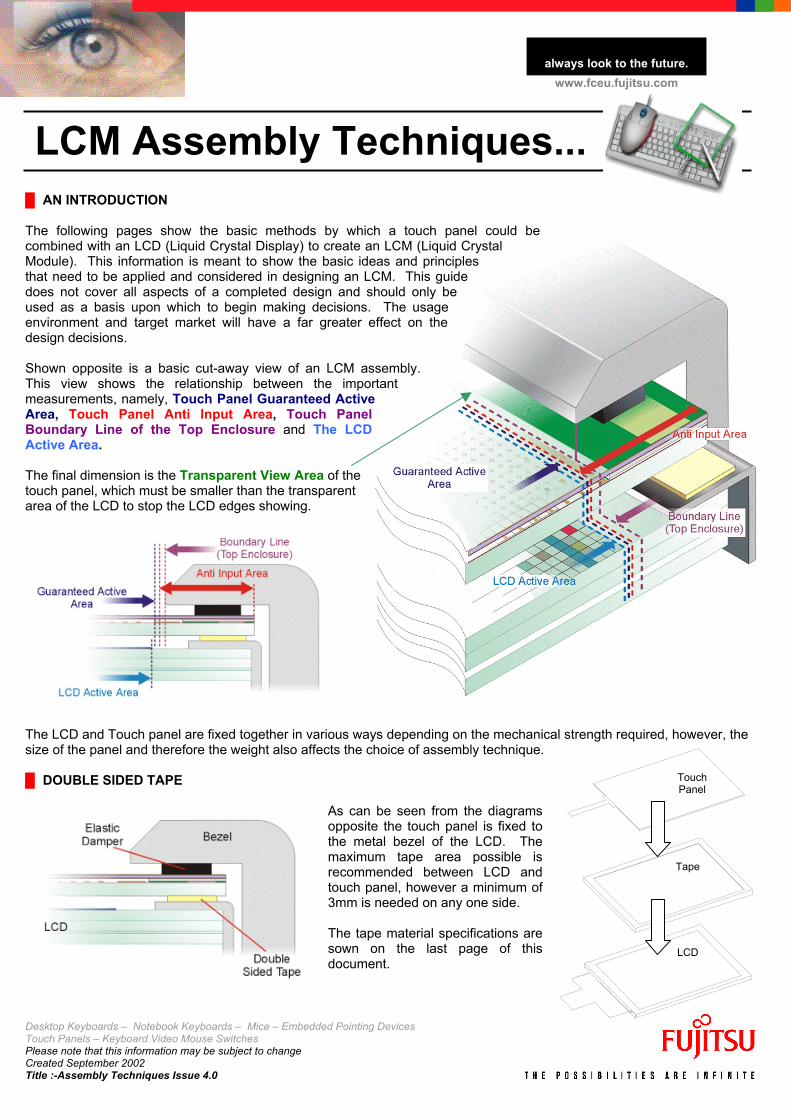
█ AN INTRODUCTION The following pages show the basic methods by which a touch panel could be combined with an LCD (Liquid Crystal Display) to create an LCM (Liquid Crystal Module). This information is meant to show the basic ideas and principles that need to be applied and considered in designing an LCM. This guide does not cover all aspects of a completed design and should only be used as a basis upon which to begin making decisions. The usage environment and target market will have a far greater effect on the design decisions. Shown opposite is a basic cut-away view of an LCM assembly. This view shows the relationship between the important measurements, namely, Touch Panel Guaranteed Active Area, Touch Panel Anti Input Area, Touch Panel Boundary Line of the Top Enclosure and The LCD Active Area. The final dimension is the Transparent View Area of the touch panel, which must be smaller than the transparent area of the LCD to stop the LCD edges showing.
The LCD and Touch panel are fixed together in various ways depending on the mechanical strength required, however, the size of the panel and therefore the weight also affects the choice of assembly technique. █ DOUBLE SIDED TAPE
As can be seen from the diagrams opposite the touch panel is fixed to the metal bezel of the LCD. The maximum tape area possible is recommended between LCD and touch panel, however a minimum of 3mm is needed on any one side. The tape material specifications are sown on the last page of this document.
LCD
Tape
Touch Panel
Desktop Keyboards – Notebook Keyboards – Mice – Embedded Pointing Devices Touch Panels – Keyboard Video Mouse Switches Please note that this information may be subject to change Created September 2002 Title :-Assembly Techniques Issue 4.0
With our products wealways look to the future.
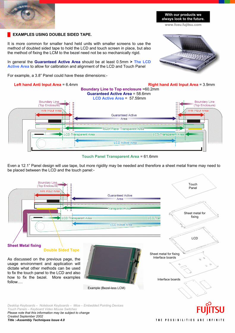
www.fceu.fujitsu.com █ EXAMPLES USING DOUBLE SIDED TAPE. It is more common for smaller hand held units with smaller screens to use the method of doubled sided tape to hold the LCD and touch screen in place, but also the method of fixing the LCM to the bezel need not be so mechanically rigid. In general the Guaranteed Active Area should be at least 0.5mm > The LCD Active Area to allow for calibration and alignment of the LCD and Touch Panel For example, a 3.8” Panel could have these dimensions:- Left hand Anti Input Area = 6.4mm Right hand Anti Input Area = 3.9mm
Boundary Line to Top enclosure =60.2mm Guaranteed Active Area = 58.6mm
LCD Active Area = 57.59mm
Touch Panel Transparent Area = 61.6mm
Even a 12.1” Panel design will use tape, but more rigidity may be needed and therefore a sheet metal frame may need to be placed between the LCD and the touch panel:-
Interface boards
Sheet metal for fixing Interface boards
LCD
Sheet metal for fixing
Touch Panel
Sheet Metal fixing Double Sided Tape As discussed on the previous page, the usage environment and application will dictate what other methods can be used to fix the touch panel to the LCD and also how to fix the bezel. More examples follow….
Example (Bezel-less LCM)
Desktop Keyboards – Notebook Keyboards – Mice – Embedded Pointing Devices Touch Panels – Keyboard Video Mouse Switches Please note that this information may be subject to change Created September 2002 Title :-Assembly Techniques Issue 4.0
With our products wealways look to the future.
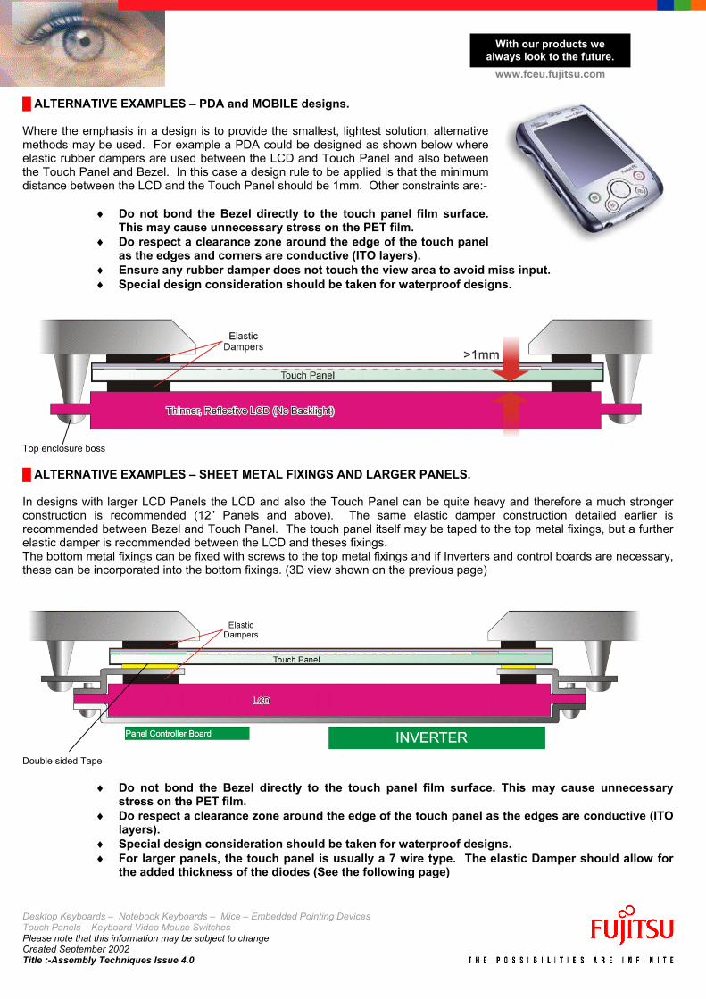
www.fceu.fujitsu.com █ ALTERNATIVE EXAMPLES – PDA and MOBILE designs. Where the emphasis in a design is to provide the smallest, lightest solution, alternative methods may be used. For example a PDA could be designed as shown below where elastic rubber dampers are used between the LCD and Touch Panel and also between the Touch Panel and Bezel. In this case a design rule to be applied is that the minimum distance between the LCD and the Touch Panel should be 1mm. Other constraints are:-
♦ Do not bond the Bezel directly to the touch panel film surface. This may cause unnecessary stress on the PET film.
♦ Do respect a clearance zone around the edge of the touch panel as the edges and corners are conductive (ITO layers).
♦ Ensure any rubber damper does not touch the view area to avoid miss input. ♦ Special design consideration should be taken for waterproof designs.
Top enclosure boss █ ALTERNATIVE EXAMPLES – SHEET METAL FIXINGS AND LARGER PANELS. In designs with larger LCD Panels the LCD and also the Touch Panel can be quite heavy and therefore a much stronger construction is recommended (12” Panels and above). The same elastic damper construction detailed earlier is recommended between Bezel and Touch Panel. The touch panel itself may be taped to the top metal fixings, but a further elastic damper is recommended between the LCD and theses fixings. The bottom metal fixings can be fixed with screws to the top metal fixings and if Inverters and control boards are necessary, these can be incorporated into the bottom fixings. (3D view shown on the previous page)
Double sided Tape
♦ Do not bond the Bezel directly to the touch panel film surface. This may cause unnecessary stress on the PET film.
♦ Do respect a clearance zone around the edge of the touch panel as the edges are conductive (ITO layers).
♦ Special design consideration should be taken for waterproof designs. ♦ For larger panels, the touch panel is usually a 7 wire type. The elastic Damper should allow for
the added thickness of the diodes (See the following page)
Desktop Keyboards – Notebook Keyboards – Mice – Embedded Pointing Devices Touch Panels – Keyboard Video Mouse Switches Please note that this information may be subject to change Created September 2002 Title :-Assembly Techniques Issue 4.0
With our products wealways look to the future.
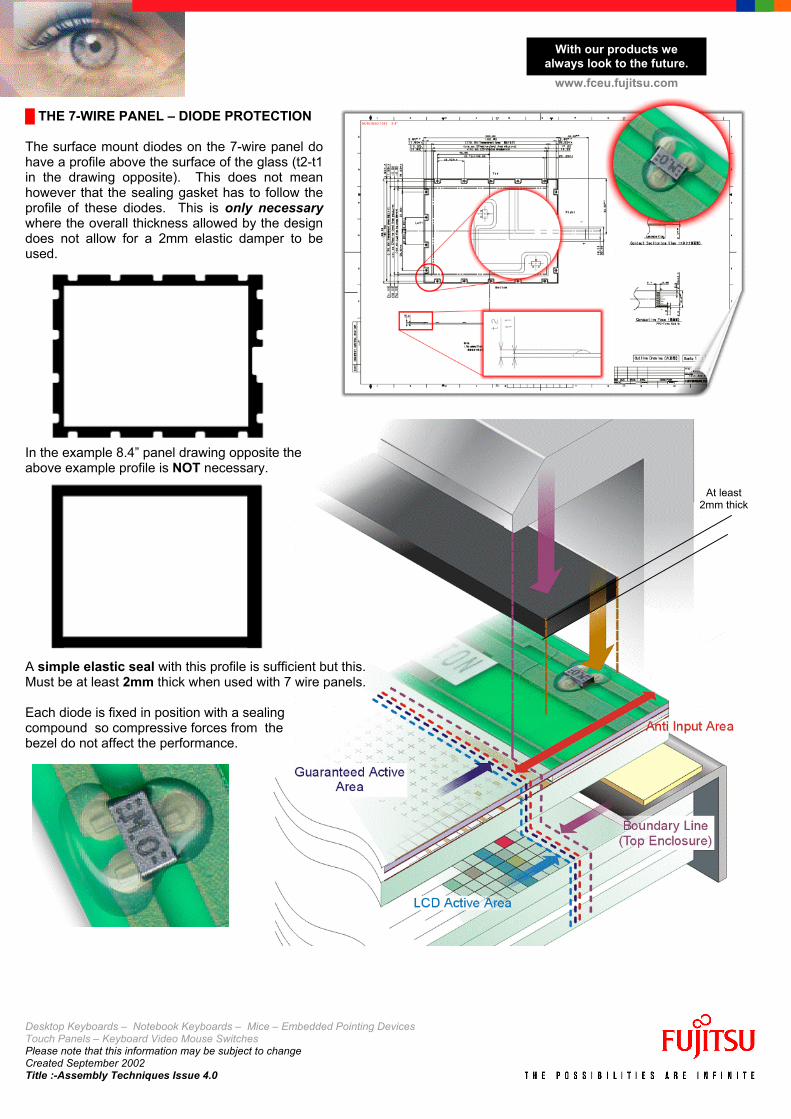
www.fceu.fujitsu.com █ THE 7-WIRE PANEL – DIODE PROTECTION The surface mount diodes on the 7-wire panel do have a profile above the surface of the glass (t2-t1 in the drawing opposite). This does not mean however that the sealing gasket has to follow the profile of these diodes. This is only necessary where the overall thickness allowed by the design does not allow for a 2mm elastic damper to be used. In the example 8.4” panel drawing opposite the above example profile is NOT necessary.
At least 2mm thick
A simple elastic seal with this profile is sufficient but this. Must be at least 2mm thick when used with 7 wire panels. Each diode is fixed in position with a sealing compound so compressive forces from the bezel do not affect the performance.
Desktop Keyboards – Notebook Keyboards – Mice – Embedded Pointing Devices Touch Panels – Keyboard Video Mouse Switches Please note that this information may be subject to change Created September 2002 Title :-Assembly Techniques Issue 4.0
With our products wealways look to the future.
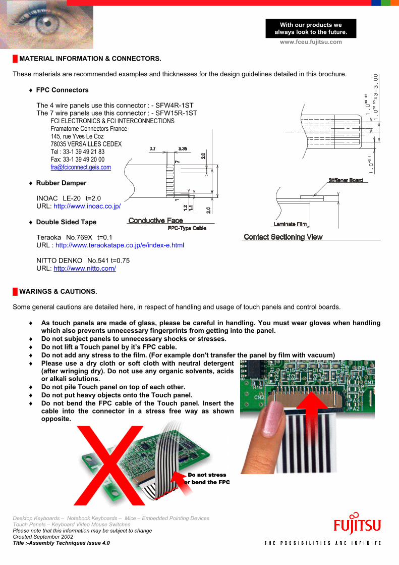
www.fceu.fujitsu.com █ MATERIAL INFORMATION & CONNECTORS. These materials are recommended examples and thicknesses for the design guidelines detailed in this brochure.
♦ FPC Connectors
The 4 wire panels use this connector : - SFW4R-1ST The 7 wire panels use this connector : - SFW15R-1ST
FCI ELECTRONICS & FCI INTERCONNECTIONS Framatome Connectors France 145, rue Yves Le Coz 78035 VERSAILLES CEDEX Tel : 33-1 39 49 21 83 Fax: 33-1 39 49 20 00 [email protected]
♦ Rubber Damper
INOAC LE-20 t=2.0 URL: http://www.inoac.co.jp/
♦ Double Sided Tape
Teraoka No.769X t=0.1 URL : http://www.teraokatape.co.jp/e/index-e.html NITTO DENKO No.541 t=0.75 URL: http://www.nitto.com/
█ WARINGS & CAUTIONS. Some general cautions are detailed here, in respect of handling and usage of touch panels and control boards.
♦ As touch panels are made of glass, please be careful in handling. You must wear gloves when handling which also prevents unnecessary fingerprints from getting into the panel.
♦ Do not subject panels to unnecessary shocks or stresses. ♦ Do not lift a Touch panel by it’s FPC cable. ♦ Do not add any stress to the film. (For example don't transfer the panel by film with vacuum) ♦ Please use a dry cloth or soft cloth with neutral detergent
(after wringing dry). Do not use any organic solvents, acids or alkali solutions.
♦ Do not pile Touch panel on top of each other. ♦ Do not put heavy objects onto the Touch panel. ♦ Do not bend the FPC cable of the Touch panel. Insert the
cable into the connector in a stress free way as shown opposite.