lc multimode & singlemode connector … multimode & singlemode connector termination...
TRANSCRIPT
LC Multimode & Singlemode Connector Termination Instructions
Put on safety glasses and preparework area by organizing allnecessary tools from the Fiber
Termination Kit (P/N: FTERM-L2), LCUpgrade Kit (P/N: FTERM-LC) and theConsumables Kit (P/N: FT-CKIT-L2). Placeprimer bottle into primer stand, remove dustcaps from fiber connectors, etc.
Note: To utilize the Alcohol Dispenser, fill itwith 99% reagent grade isopropyl alcohol (notincluded). Replace cap into the pump position.
A
Using the buffer strippers, strip offthe buffer in at least two pieces.
Note 1: Attempting to strip the entire length ofbuffer in one swipe will typically result inbreakage. Note 2: Be sure the tool blade area is free ofbuffer debris.
5Using a dry, lint-free wipe;Remove any remnants of the
protective coating on the fiber afterstripping the buffer.Important : Ensure that all remnants of thecoating are removed or the fiber will not fitinto the connector.DO NOT touch fiber after cleaning.
6
Slide the strain relief boot (andcrimp sleeve for jacketed fiber) over
the fiber in the proper orientation as shown. For duplex LC connectors, orient the A/B clipwith the letters facing the strain relief bootsas shown, also see step 29 for proper polarity.
Note: For Jacketed fiber orient the crimpsleeve such that the shrink tube end isinstalled onto the cable first.
2Using the marker pen and thetemplate card provided, measure
and mark the buffer strip length as shown onthe template.
4
Insert primer bottle into thestand. Dip the entire exposed
fiber into the LightSpeed® primer andplace in a protected area.Note: It is important that the entire exposedfiber be coated with the primer includingsome portion of the buffer material. Forjacketed terminations, do not be concernedwith keeping the kevlar strands out of theprimer solution.
7
Remove cap from theLightSpeed® adhesive syringe by
unthreading it. Install the metal syringe tipprovided by threading it onto cartridgeuntil it locks.Note: Save the syringe cap to re-cap when apartially used syringe is returned to the casefor later use.
1
Expiration Datemm/dd/yy
Important!!To avoid possible fiber breakage,
do not insert the fiber so far that it con-tacts the bottom of the primer bottle!! Theprimer bottle label indicates the minimumusable depth.
Note: Cap the bottle when not in use toavoid contamination. Store both primer andadhesive between 40° F (4.4° C) and 100° F(38° C).
8
ExpirationDate
mm/dd/yy
Minimum usable depthline
900 Micron Buffered
1.6 mm Simplex Jacketed
1.6 mm Duplex Jacketed
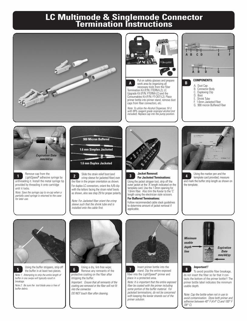
COMPONENTS:
A. Dust Cap B. Connector BodyC. Duplexing ClipD. BootE. Shrink TubeF. 1.6mm Jacketed FiberG. 900 micron Buffered Fiber
B
Jacket Removal: For Jacketed Terminations:
Using the jacket stripper tool, strip off theouter jacket at the ‘A’ length indicated on thetemplate card. Use the 1.0mm opening for1.6mm fiber. Also trim the Kevlar to the ‘C’length using the electrician style scissors.For Buffered Terminations:Follow recommended cable slack guidelinesto determine amount of jacket removal ifapplicable.
3
A B C D E F
A B D G
Jacketed Fiber OnlySlide the crimp sleeve up over the
kevlar so that it is seated against theshoulder of the connector housing, beingsure the sleeve does not move prior tobeing crimped. Position the crimp tool overthe crimp sleeve using the 0.12 in. openingin the crimp die. Crimp the sleeve by clos-ing the crimp tool completely and releas-ing. Crimp only once.
LC Multimode & Singlemode Connector Termination Instructions
Hold the flat surface of the scribetool flat against the ferrule tip
with the beveled edge facing up. Carefullyscore the fiber close to the intersection ofthe ferrule tip and fiber. Score on one sideonly. Clean the adhesive off blade.Note: Do not use excessive pressure to pre-vent fiber breakage and uneven fractures. Ifbreakage occurs see note 2 in next step.
11Remove the excess fiber with astraight, non-twisting pull and
deposit in a safe place (i.e. onto a piece oftape or in the debris container).Note1: If fiber does not readily pull off,repeat previous step – scoring on oppositeside of fiber.Note 2: Fiber pieces are difficult to see. Ifnot properly disposed, glass fibers maycause serious injury.Note 3: Be careful not to bump or brushend-face before polishing.
12
13Jacketed Fiber OnlyUsing the small propane torch
from the FTERM-LC or equivalent, carefullyheat up the shrink tubing on all sides toprovide proper strain relief. Note: Hold torch several inches from cablebeing careful not to overheat the tubing orcable to prevent damage.
14
#2 Film (Pink):Place the polishing pad onto a flat
surface with the rubber side facing up.Place the #2 film onto the polishing padwith the glossy side of film down. Note: Prior to polishing, clean pad surfacewith alcohol soaked wipe to provide for asmooth polishing surface. This will alsoallow the polishing paper to stick in place.(Ensure no air is trapped between pad andfilm). Also clean polishing puck.
17
Simplex cable onlySlide the boot up into place onto
the crimp sleeve (jacketed fiber) or connec-tor housing barrel (buffered fiber). Forduplex jacketed cable, do not slide bootsup until after polishing is complete.
15
#1 Film (Gray):Perform an "air polish" by holding
the connector in one hand and the #1polishing film in the other. Gently brushthe dull side of the polishing film in a“figure 8” fashion against the ferrule tip towear the small fiber protrusion into asmoother, more polishable tip. Continueuntil the tip is almost flush with the ferrule.
16Gently grip the connector and applymedium pressure and polish in a
50-75mm [2-3 in.] "figure 8" pattern for 25 to30 revolutions.Important: Do not over-polish and do not useexcessive pressure. See Step 19b for efficient use of polishing film.
19aAdd a minimum of 3 or 4 drops ofdistilled/deionized water on the
polishing film and carefully insert theconnector ferrule into the LC compatiblepolishing puck (provided with the FTERM-LC) and gently place on pad. Avoidbumping ferule tip on puck or crushingexposed fiber onto pad.
18
Remove dust cap from theconnector and insert the adhesive
syringe tip into connector housing until itseats firmly inside. Inject the LightSpeedadhesive until a small dot of the adhesiveappears at the ferrule tip. Also inject asmall amount of adhesive into the back endof the connector. This ensures bonding ofthe buffer to the connector, strengtheningthe termination. Be careful not to overfillto prevent a backflow of adhesive.
9Insert the fiber into the connectoruntil the buffer bottoms out inside
the housing. Allow at least 30 seconds curetime before proceeding. Tip: Rotate theconnector during insertion to assist inguiding the fiber into the ferrule. Forjacketed fiber, allow the kevlar to fan outaround the connector barrel.Note: Once primer coated fiber touches theadhesive it will start curing instantly. Fiberinsertion will become increasingly more difficultif not fully inserted within 10 to 15 seconds.
10
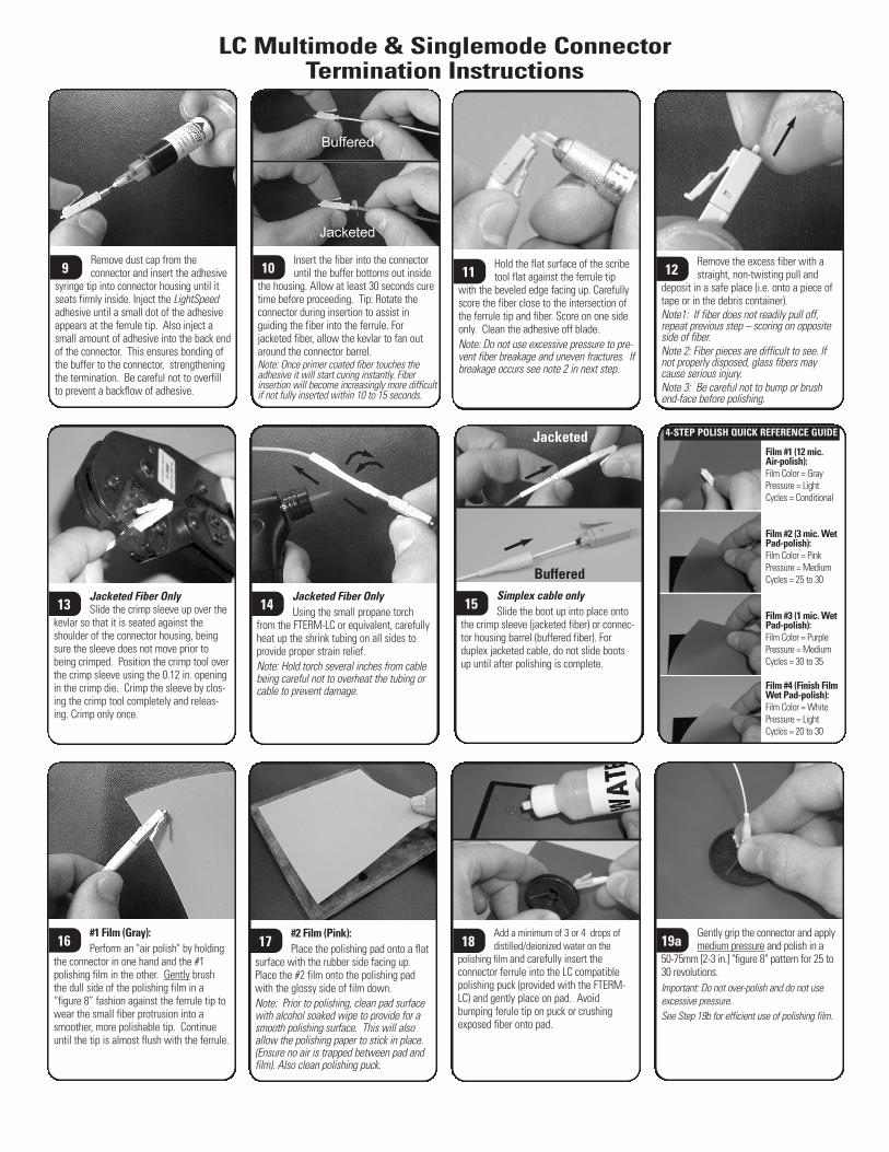
Film #1 (12 mic. Air-polish):Film Color = GrayPressure = LightCycles = Conditional
Film #2 (3 mic. WetPad-polish):Film Color = PinkPressure = MediumCycles = 25 to 30
Film #3 (1 mic. WetPad-polish):Film Color = PurplePressure = MediumCycles = 30 to 35
Film #4 (Finish FilmWet Pad-polish):Film Color = WhitePressure = LightCycles = 20 to 30
Jacketed
Buffered
4-STEP POLISH QUICK REFERENCE GUIDE
LC Multimode & Singlemode Connector Termination Instructions
Prior to viewing endface ofconnector with microscope clean
with a dry lint-free wipe.23
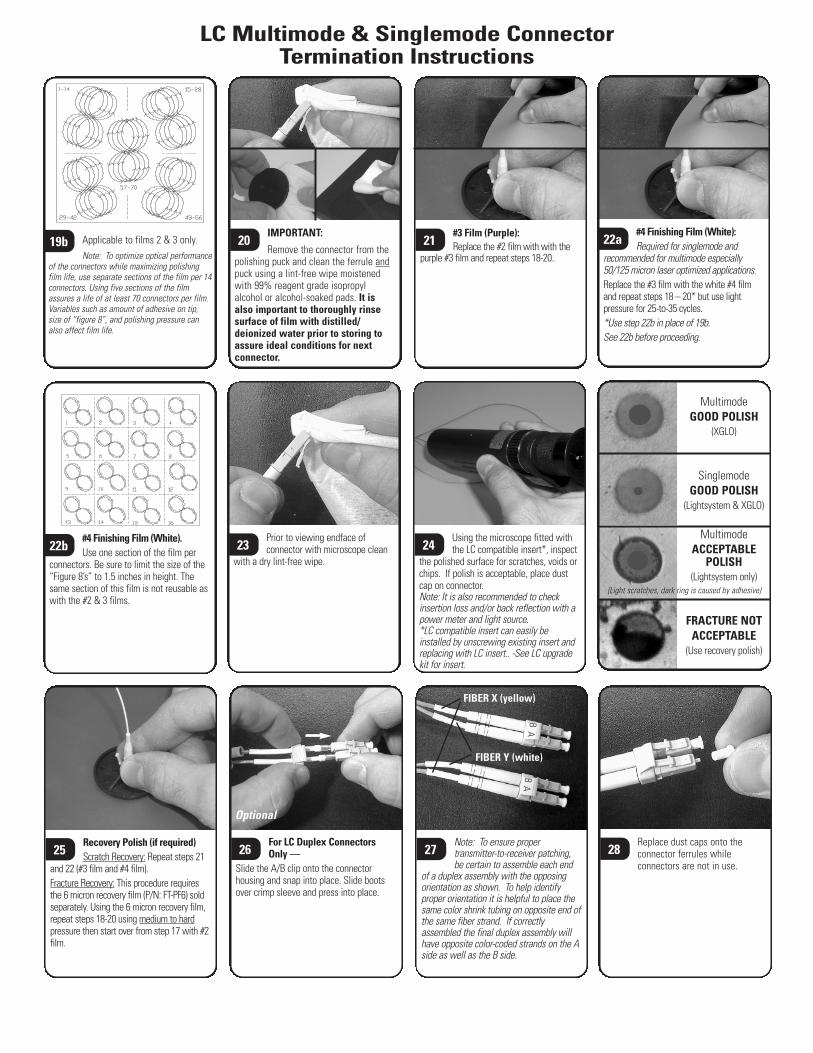
Using the microscope fitted withthe LC compatible insert*, inspect
the polished surface for scratches, voids orchips. If polish is acceptable, place dustcap on connector.Note: It is also recommended to checkinsertion loss and/or back reflection with apower meter and light source.*LC compatible insert can easily beinstalled by unscrewing existing insert andreplacing with LC insert.. -See LC upgradekit for insert.
24
Replace dust caps onto theconnector ferrules whileconnectors are not in use.
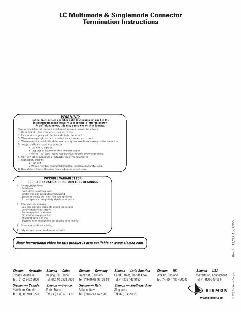
28Note: To ensure propertransmitter-to-receiver patching,be certain to assemble each end
of a duplex assembly with the opposingorientation as shown. To help identifyproper orientation it is helpful to place thesame color shrink tubing on opposite end ofthe same fiber strand. If correctlyassembled the final duplex assembly willhave opposite color-coded strands on the Aside as well as the B side.
27For LC Duplex ConnectorsOnly —
Slide the A/B clip onto the connectorhousing and snap into place. Slide bootsover crimp sleeve and press into place.
26
FIBER X (yellow)
FIBER Y (white)
BB
AA
IMPORTANT:
Remove the connector from thepolishing puck and clean the ferrule andpuck using a lint-free wipe moistenedwith 99% reagent grade isopropylalcohol or alcohol-soaked pads. It isalso important to thoroughly rinsesurface of film with distilled/deionized water prior to storing toassure ideal conditions for nextconnector.
20#3 Film (Purple):Replace the #2 film with with the
purple #3 film and repeat steps 18-20..
21Applicable to films 2 & 3 only.Note: To optimize optical performance
of the connectors while maximizing polishingfilm life, use separate sections of the film per 14connectors. Using five sections of the filmassures a life of at least 70 connectors per film.Variables such as amount of adhesive on tip,size of “figure 8”, and polishing pressure canalso affect film life.
19b
#4 Finishing Film (White).Use one section of the film per
connectors. Be sure to limit the size of the“Figure 8’s” to 1.5 inches in height. Thesame section of this film is not reusable aswith the #2 & 3 films.
22b
#4 Finishing Film (White):Required for singlemode and
recommended for multimode especially50/125 micron laser optimized applications.Replace the #3 film with the white #4 filmand repeat steps 18 – 20* but use lightpressure for 25-to-35 cycles.*Use step 22b in place of 19b.See 22b before proceeding.
22a
MultimodeGOOD POLISH
(XGLO)
SinglemodeGOOD POLISH
(Lightsystem & XGLO)
MultimodeACCEPTABLE
POLISH(Lightsystem only)
FRACTURE NOTACCEPTABLE
(Use recovery polish)
Recovery Polish (if required)Scratch Recovery: Repeat steps 21
and 22 (#3 film and #4 film).Fracture Recovery: This procedure requiresthe 6 micron recovery film (P/N: FT-PF6) soldseparately. Using the 6 micron recovery film,repeat steps 18-20 using medium to hardpressure then start over from step 17 with #2film.
25
Optional
(Light scratches, dark ring is caused by adhesive)
Rev
. F
11/0
3
100.8
955
© 2
003
The
Siem
on C
ompa
ny
LC Multimode & Singlemode Connector Termination Instructions
WARNING:Optical transmitters and fiber optic test equipment used in the
telecommunications industry uses invisible infrared energy.At sufficient power, this may cause eye or skin damage.
If you work with fiber optic products, including test equipment, consider the following:1. Do not look into fibers or connectors. They may be ‘live’.2. Know what is happening with the fiber under test at the far end!3. When connecting a light source, try to make it the last element you connect!4. Whenever possible, switch off and disconnect your light source(s) before breaking any fiber connections.5. Always consider the hazard to other people:
a. Use warning signs, etc.b. Keep caps on unconnected fibers whenever possible.c. If using “live” optical beams, keep them low and facing away from personnel.
6. Don’t view optical outputs with a microscope, use a TV camera/monitor.7. Elect a safety officer to:
a. Train staffb. Maintain records of equipment classification, calibrations and safety checks.
8. Be careful of cut fibers. Remember they are sharp and difficult to see!
POSSIBLE VARIABLES FORPOOR ATTENUATION OR RETURN LOSS READINGS
1. Fractured/broken fibers:- Dull cleaver- Dried adhesive on cleaver blade- Twisted or uneven pulling when removing stub- Bumped or brushed end-face of fiber before polishing- Too much pressure during initial pad polish or air polish
2. Adhesive/primer not curing:- Date code expired or exposed to extreme temperatures- Contaminated primer/adhesive- Not enough primer or adhesive- Did not allow enough cure time- Movement during cure time- Excessive buffer length pushing out adhesive during insertion
3. Excessive or insufficient polishing
4 Dirty pad, puck, paper, or end-face of connector
Note: Instructional video for this product is also available at www.siemon.com
www.siemon.com
Siemon — UKWoking, EnglandTel: (44) (0) 1483 480040
Siemon — USAWatertown, ConnecticutTel: (1) 866-548-5814
Siemon — Australia Sydney, AustraliaTel: (61) 2 9452 2666
Siemon — Canada Markham, OntarioTel: (1) 905 940 9223
Siemon — China Beijing, P.R. ChinaTel: (86) 10 6559 8860
Siemon — FranceParis, FranceTel: (33) 1 46 46 11 85
Siemon — Germany Frankfurt, GermanyTel: (49) (0) 69 97168 184
Siemon — ItalyMilano, ItalyTel: (39) 02 64 672 209
Siemon — Latin America Coral Gables, Florida USATel: (1) 305 446 9150
Siemon — Southeast Asia SingaporeTel: (65) 345 9119