layer 2 bridging and switching configuration guidefor ...commands,files,and directories; ......
TRANSCRIPT

Junos® OS
Layer 2BridgingandSwitchingConfigurationGuidefor Security Devices
Release
11.4
Published: 2011-11-02
Copyright © 2011, Juniper Networks, Inc.

Juniper Networks, Inc.1194 North Mathilda AvenueSunnyvale, California 94089USA408-745-2000www.juniper.net
This product includes the Envoy SNMP Engine, developed by Epilogue Technology, an Integrated Systems Company. Copyright © 1986-1997,Epilogue Technology Corporation. All rights reserved. This program and its documentation were developed at private expense, and no partof them is in the public domain.
This product includes memory allocation software developed by Mark Moraes, copyright © 1988, 1989, 1993, University of Toronto.
This product includes FreeBSD software developed by the University of California, Berkeley, and its contributors. All of the documentationand software included in the 4.4BSD and 4.4BSD-Lite Releases is copyrighted by the Regents of the University of California. Copyright ©1979, 1980, 1983, 1986, 1988, 1989, 1991, 1992, 1993, 1994. The Regents of the University of California. All rights reserved.
GateD software copyright © 1995, the Regents of the University. All rights reserved. Gate Daemon was originated and developed throughrelease 3.0 by Cornell University and its collaborators. Gated is based on Kirton’s EGP, UC Berkeley’s routing daemon (routed), and DCN’sHELLO routing protocol. Development of Gated has been supported in part by the National Science Foundation. Portions of the GateDsoftware copyright © 1988, Regents of the University of California. All rights reserved. Portions of the GateD software copyright © 1991, D.L. S. Associates.
This product includes software developed by Maker Communications, Inc., copyright © 1996, 1997, Maker Communications, Inc.
Juniper Networks, Junos, Steel-Belted Radius, NetScreen, and ScreenOS are registered trademarks of Juniper Networks, Inc. in the UnitedStates and other countries. The Juniper Networks Logo, the Junos logo, and JunosE are trademarks of Juniper Networks, Inc. All othertrademarks, service marks, registered trademarks, or registered service marks are the property of their respective owners.
Juniper Networks assumes no responsibility for any inaccuracies in this document. Juniper Networks reserves the right to change, modify,transfer, or otherwise revise this publication without notice.
Products made or sold by Juniper Networks or components thereof might be covered by one or more of the following patents that areowned by or licensed to Juniper Networks: U.S. Patent Nos. 5,473,599, 5,905,725, 5,909,440, 6,192,051, 6,333,650, 6,359,479, 6,406,312,6,429,706, 6,459,579, 6,493,347, 6,538,518, 6,538,899, 6,552,918, 6,567,902, 6,578,186, and 6,590,785.
Junos OS Layer 2 Bridging and Switching Configuration Guide for Security DevicesRelease 11.4Copyright © 2011, Juniper Networks, Inc.All rights reserved.
Revision HistoryNovember 2011—R1 Junos OS 11.4
The information in this document is current as of the date listed in the revision history.
YEAR 2000 NOTICE
Juniper Networks hardware and software products are Year 2000 compliant. Junos OS has no known time-related limitations through theyear 2038. However, the NTP application is known to have some difficulty in the year 2036.
SOFTWARE LICENSE
The terms and conditions for using this software are described in the software license contained in the acknowledgment to your purchaseorder or, to the extent applicable, to any reseller agreement or end-user purchase agreement executed between you and Juniper Networks.By using this software, you indicate that you understand and agree to be bound by those terms and conditions. Generally speaking, thesoftware license restricts the manner in which you are permitted to use the software and may contain prohibitions against certain uses.The software license may state conditions under which the license is automatically terminated. You should consult the license for furtherdetails. For complete product documentation, please see the Juniper Networks Web site at www.juniper.net/techpubs.
Copyright © 2011, Juniper Networks, Inc.ii

ENDUSER LICENSE AGREEMENT
The Juniper Networks product that is the subject of this technical documentation consists of (or is intended for use with) Juniper Networkssoftware. Use of such software is subject to the terms and conditions of the End User License Agreement (“EULA”) posted at
http://www.juniper.net/support/eula.html. By downloading, installing or using such software, you agree to the terms and conditionsof that EULA.
iiiCopyright © 2011, Juniper Networks, Inc.

Copyright © 2011, Juniper Networks, Inc.iv
Abbreviated Table of Contents
About This Guide . . . . . . . . . . . . . . . . . . . . . . . . . . . . . . . . . . . . . . . . . . . . . . . . . . xi
Part 1 Layer 2 Bridging and Switching
Chapter 1 Configuring Ethernet Ports for Switching . . . . . . . . . . . . . . . . . . . . . . . . . . . . . . 3
Chapter 2 Configuring Layer 2 Bridging and Transparent Mode . . . . . . . . . . . . . . . . . . . 45
Part 2 Index
Index . . . . . . . . . . . . . . . . . . . . . . . . . . . . . . . . . . . . . . . . . . . . . . . . . . . . . . . . . . . . 89
vCopyright © 2011, Juniper Networks, Inc.

Copyright © 2011, Juniper Networks, Inc.vi
Junos OS Layer 2 Bridging and Switching Configuration Guide for Security Devices

Table of Contents
About This Guide . . . . . . . . . . . . . . . . . . . . . . . . . . . . . . . . . . . . . . . . . . . . . . . . . . xi
J Series and SRX Series Documentation and Release Notes . . . . . . . . . . . . . . . . . . xi
Objectives . . . . . . . . . . . . . . . . . . . . . . . . . . . . . . . . . . . . . . . . . . . . . . . . . . . . . . . . . xii
Audience . . . . . . . . . . . . . . . . . . . . . . . . . . . . . . . . . . . . . . . . . . . . . . . . . . . . . . . . . . xii
Supported Routing Platforms . . . . . . . . . . . . . . . . . . . . . . . . . . . . . . . . . . . . . . . . . xii
Document Conventions . . . . . . . . . . . . . . . . . . . . . . . . . . . . . . . . . . . . . . . . . . . . . . xii
Documentation Feedback . . . . . . . . . . . . . . . . . . . . . . . . . . . . . . . . . . . . . . . . . . . . xiv
Requesting Technical Support . . . . . . . . . . . . . . . . . . . . . . . . . . . . . . . . . . . . . . . . xiv
Self-Help Online Tools and Resources . . . . . . . . . . . . . . . . . . . . . . . . . . . . . . xiv
Opening a Case with JTAC . . . . . . . . . . . . . . . . . . . . . . . . . . . . . . . . . . . . . . . . . xv
Part 1 Layer 2 Bridging and Switching
Chapter 1 Configuring Ethernet Ports for Switching . . . . . . . . . . . . . . . . . . . . . . . . . . . . . . 3
Ethernet Ports Switching Overview . . . . . . . . . . . . . . . . . . . . . . . . . . . . . . . . . . . . . . 3
Supported Devices and Ports . . . . . . . . . . . . . . . . . . . . . . . . . . . . . . . . . . . . . . . 3
Integrated Bridging and Routing . . . . . . . . . . . . . . . . . . . . . . . . . . . . . . . . . . . . . 4
Link Layer Discovery Protocol and LLDP-Media Endpoint Discovery . . . . . . . . 4
Types of Switch Ports . . . . . . . . . . . . . . . . . . . . . . . . . . . . . . . . . . . . . . . . . . . . . 6
uPIM in a Daisy Chain . . . . . . . . . . . . . . . . . . . . . . . . . . . . . . . . . . . . . . . . . . . . . 6
Q-in-Q VLAN Tagging . . . . . . . . . . . . . . . . . . . . . . . . . . . . . . . . . . . . . . . . . . . . . 7
Switching Modes . . . . . . . . . . . . . . . . . . . . . . . . . . . . . . . . . . . . . . . . . . . . . . . . . . . . 8
Understanding Switching Modes . . . . . . . . . . . . . . . . . . . . . . . . . . . . . . . . . . . . 8
Example: Configuring Switching Modes . . . . . . . . . . . . . . . . . . . . . . . . . . . . . . . 8
Verifying Switching Mode Configuration . . . . . . . . . . . . . . . . . . . . . . . . . . . . . . 9
VLANs . . . . . . . . . . . . . . . . . . . . . . . . . . . . . . . . . . . . . . . . . . . . . . . . . . . . . . . . . . . . 10
Understanding VLANs . . . . . . . . . . . . . . . . . . . . . . . . . . . . . . . . . . . . . . . . . . . . 10
Example: Configuring VLANs . . . . . . . . . . . . . . . . . . . . . . . . . . . . . . . . . . . . . . . 12
Spanning Tree Protocol . . . . . . . . . . . . . . . . . . . . . . . . . . . . . . . . . . . . . . . . . . . . . . 13
Understanding the Spanning Tree Protocol . . . . . . . . . . . . . . . . . . . . . . . . . . . 13
Configuring the Spanning Tree Protocol . . . . . . . . . . . . . . . . . . . . . . . . . . . . . . 17
Link Aggregation Control Protocol . . . . . . . . . . . . . . . . . . . . . . . . . . . . . . . . . . . . . . 18
Understanding Link Aggregation Control Protocol . . . . . . . . . . . . . . . . . . . . . . 18
Link Aggregation Benefits . . . . . . . . . . . . . . . . . . . . . . . . . . . . . . . . . . . . . 18
Link Aggregation Configuration Guidelines . . . . . . . . . . . . . . . . . . . . . . . . 19
Example: Configuring Link Aggregation Control Protocol . . . . . . . . . . . . . . . . 21
802.1X Port-Based Network Authentication . . . . . . . . . . . . . . . . . . . . . . . . . . . . . . 23
Understanding 802.1X Port-Based Network Authentication . . . . . . . . . . . . . 23
Dynamic VLAN Assignment . . . . . . . . . . . . . . . . . . . . . . . . . . . . . . . . . . . 24
MAC RADIUS Authentication . . . . . . . . . . . . . . . . . . . . . . . . . . . . . . . . . . 25
Static MAC Bypass . . . . . . . . . . . . . . . . . . . . . . . . . . . . . . . . . . . . . . . . . . . 25
viiCopyright © 2011, Juniper Networks, Inc.

Guest VLAN . . . . . . . . . . . . . . . . . . . . . . . . . . . . . . . . . . . . . . . . . . . . . . . . 25
RADIUS Server Failure Fallback . . . . . . . . . . . . . . . . . . . . . . . . . . . . . . . . . 25
VoIP VLAN Support . . . . . . . . . . . . . . . . . . . . . . . . . . . . . . . . . . . . . . . . . . 27
RADIUS Accounting . . . . . . . . . . . . . . . . . . . . . . . . . . . . . . . . . . . . . . . . . . 28
Server Reject VLAN . . . . . . . . . . . . . . . . . . . . . . . . . . . . . . . . . . . . . . . . . . 28
Example: Configuring 802.1x Authentication . . . . . . . . . . . . . . . . . . . . . . . . . . 28
Example: Specifying RADIUS Server Connections on the Device . . . . . . . . . . 29
Example: Configuring 802.1x Interface Settings . . . . . . . . . . . . . . . . . . . . . . . 32
Example: Configuring a Guest VLAN . . . . . . . . . . . . . . . . . . . . . . . . . . . . . . . . 34
Port Security . . . . . . . . . . . . . . . . . . . . . . . . . . . . . . . . . . . . . . . . . . . . . . . . . . . . . . . 35
Port Security Overview . . . . . . . . . . . . . . . . . . . . . . . . . . . . . . . . . . . . . . . . . . . 35
Understanding MAC Limiting . . . . . . . . . . . . . . . . . . . . . . . . . . . . . . . . . . . . . . 36
Example: Configuring MAC Limiting . . . . . . . . . . . . . . . . . . . . . . . . . . . . . . . . . 37
IGMP Snooping . . . . . . . . . . . . . . . . . . . . . . . . . . . . . . . . . . . . . . . . . . . . . . . . . . . . 39
Understanding IGMP Snooping . . . . . . . . . . . . . . . . . . . . . . . . . . . . . . . . . . . . 39
How IGMP Snooping Works . . . . . . . . . . . . . . . . . . . . . . . . . . . . . . . . . . . 39
How Hosts Join and Leave Multicast Groups . . . . . . . . . . . . . . . . . . . . . . 40
Example: Configuring IGMP Snooping . . . . . . . . . . . . . . . . . . . . . . . . . . . . . . . 41
GARP VLAN Registration Protocol . . . . . . . . . . . . . . . . . . . . . . . . . . . . . . . . . . . . . 42
Understanding GARP VLAN Registration Protocol . . . . . . . . . . . . . . . . . . . . . 42
Example: Configuring GARP VLAN Registration Protocol . . . . . . . . . . . . . . . . 43
Chapter 2 Configuring Layer 2 Bridging and Transparent Mode . . . . . . . . . . . . . . . . . . . 45
Layer 2 Bridging and Transparent Mode Overview . . . . . . . . . . . . . . . . . . . . . . . . . 45
Layer 2 Bridging Exceptions on SRX Series Devices . . . . . . . . . . . . . . . . . . . . 46
Bridge Domains . . . . . . . . . . . . . . . . . . . . . . . . . . . . . . . . . . . . . . . . . . . . . . . . . . . . 47
Understanding Bridge Domains . . . . . . . . . . . . . . . . . . . . . . . . . . . . . . . . . . . . 47
Example: Configuring Bridge Domains . . . . . . . . . . . . . . . . . . . . . . . . . . . . . . 48
Layer 2 Interfaces . . . . . . . . . . . . . . . . . . . . . . . . . . . . . . . . . . . . . . . . . . . . . . . . . . . 49
Understanding Transparent Mode Conditions . . . . . . . . . . . . . . . . . . . . . . . . 49
Understanding Layer 2 Interfaces . . . . . . . . . . . . . . . . . . . . . . . . . . . . . . . . . . 50
Example: Configuring Layer 2 Logical Interfaces . . . . . . . . . . . . . . . . . . . . . . . 51
Understanding VLAN Retagging . . . . . . . . . . . . . . . . . . . . . . . . . . . . . . . . . . . . 52
Example: Configuring VLAN Retagging . . . . . . . . . . . . . . . . . . . . . . . . . . . . . . 53
Understanding Integrated Routing and Bridging Interfaces . . . . . . . . . . . . . . 54
Example: Configuring an IRB Interface . . . . . . . . . . . . . . . . . . . . . . . . . . . . . . . 54
Layer 2 Security Zones and Security Policies . . . . . . . . . . . . . . . . . . . . . . . . . . . . . 56
Understanding Layer 2 Security Zones . . . . . . . . . . . . . . . . . . . . . . . . . . . . . . 56
Example: Configuring Layer 2 Security Zones . . . . . . . . . . . . . . . . . . . . . . . . . 57
Understanding Security Policies in Transparent Mode . . . . . . . . . . . . . . . . . . 58
Example: Configuring Security Policies in Transparent Mode . . . . . . . . . . . . . 59
Understanding Firewall User Authentication in Transparent Mode . . . . . . . . . . . . 61
Understanding Layer 2 Forwarding Tables . . . . . . . . . . . . . . . . . . . . . . . . . . . . . . . 62
Example: Configuring the Default Learning for Unknown MAC Addresses . . . . . . 63
Understanding Layer 2 Transparent Mode Chassis Clusters . . . . . . . . . . . . . . . . . 64
Example: Configuring Redundant Ethernet Interfaces for Layer 2 Transparent
Mode Chassis Clusters . . . . . . . . . . . . . . . . . . . . . . . . . . . . . . . . . . . . . . . . . . . 66
Copyright © 2011, Juniper Networks, Inc.viii
Junos OS Layer 2 Bridging and Switching Configuration Guide for Security Devices
Transparent Mode Devices . . . . . . . . . . . . . . . . . . . . . . . . . . . . . . . . . . . . . . . . . . . 67
Class of Service Functions in Transparent Mode Overview . . . . . . . . . . . . . . 68
Understanding BA Traffic Classification on Transparent Mode Devices . . . . 68
Example: Configuring BA Classifiers on Transparent Mode Devices . . . . . . . 69
Understanding Rewrite of Packet Headers on Transparent Mode
Devices . . . . . . . . . . . . . . . . . . . . . . . . . . . . . . . . . . . . . . . . . . . . . . . . . . . . 71
Example: Configuring Rewrite Rules on Transparent Mode Devices . . . . . . . . 72
Example: Configuring Layer 2 Trunk Interfaces with Multiple Units . . . . . . . . . . . . 74
Part 2 Index
Index . . . . . . . . . . . . . . . . . . . . . . . . . . . . . . . . . . . . . . . . . . . . . . . . . . . . . . . . . . . . . 89
ixCopyright © 2011, Juniper Networks, Inc.
Table of Contents

Copyright © 2011, Juniper Networks, Inc.x
Junos OS Layer 2 Bridging and Switching Configuration Guide for Security Devices

About This Guide
This preface provides the following guidelines for using the Junos OS Layer 2 Bridging and
Switching Configuration Guide for Security Devices:
• J Series and SRX Series Documentation and Release Notes on page xi
• Objectives on page xii
• Audience on page xii
• Supported Routing Platforms on page xii
• Document Conventions on page xii
• Documentation Feedback on page xiv
• Requesting Technical Support on page xiv
J Series and SRX Series Documentation and Release Notes
For a list of related J Series documentation, see
http://www.juniper.net/techpubs/software/junos-jseries/index-main.html .
For a list of related SRX Series documentation, see
http://www.juniper.net/techpubs/hardware/srx-series-main.html .
If the information in the latest release notes differs from the information in the
documentation, follow the Junos OS Release Notes.
To obtain the most current version of all Juniper Networks®
technical documentation,
see the product documentation page on the Juniper Networks website at
http://www.juniper.net/techpubs/.
Juniper Networks supports a technical book program to publish books by Juniper Networks
engineers and subject matter experts with book publishers around the world. These
books go beyond the technical documentation to explore the nuances of network
architecture, deployment, and administration using the Junos operating system (Junos
OS) and Juniper Networks devices. In addition, the Juniper Networks Technical Library,
published in conjunction with O'Reilly Media, explores improving network security,
reliability, and availability using Junos OS configuration techniques. All the books are for
sale at technical bookstores and book outlets around the world. The current list can be
viewed at http://www.juniper.net/books .
xiCopyright © 2011, Juniper Networks, Inc.
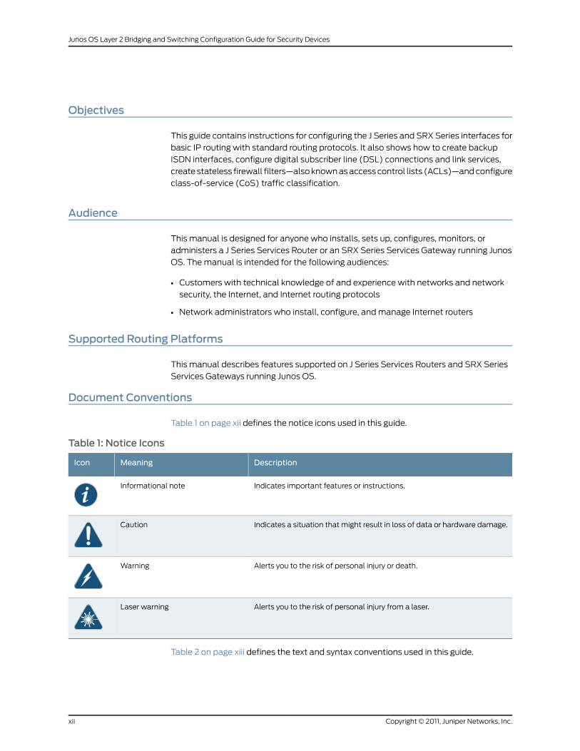
Objectives
This guide contains instructions for configuring the J Series and SRX Series interfaces for
basic IP routing with standard routing protocols. It also shows how to create backup
ISDN interfaces, configure digital subscriber line (DSL) connections and link services,
create stateless firewall filters—also known as access control lists (ACLs)—and configure
class-of-service (CoS) traffic classification.
Audience
This manual is designed for anyone who installs, sets up, configures, monitors, or
administers a J Series Services Router or an SRX Series Services Gateway running Junos
OS. The manual is intended for the following audiences:
• Customers with technical knowledge of and experience with networks and network
security, the Internet, and Internet routing protocols
• Network administrators who install, configure, and manage Internet routers
Supported Routing Platforms
This manual describes features supported on J Series Services Routers and SRX Series
Services Gateways running Junos OS.
Document Conventions
Table 1 on page xii defines the notice icons used in this guide.
Table 1: Notice Icons
DescriptionMeaningIcon
Indicates important features or instructions.Informational note
Indicates a situation that might result in loss of data or hardware damage.Caution
Alerts you to the risk of personal injury or death.Warning
Alerts you to the risk of personal injury from a laser.Laser warning
Table 2 on page xiii defines the text and syntax conventions used in this guide.
Copyright © 2011, Juniper Networks, Inc.xii
Junos OS Layer 2 Bridging and Switching Configuration Guide for Security Devices

Table 2: Text and Syntax Conventions
ExamplesDescriptionConvention
To enter configuration mode, type theconfigure command:
user@host> configure
Represents text that you type.Bold text like this
user@host> show chassis alarms
No alarms currently active
Represents output that appears on theterminal screen.
Fixed-width text like this
• A policy term is a named structurethat defines match conditions andactions.
• JunosOSSystemBasicsConfigurationGuide
• RFC 1997,BGPCommunities Attribute
• Introduces important new terms.
• Identifies book names.
• Identifies RFC and Internet draft titles.
Italic text like this
Configure the machine’s domain name:
[edit]root@# set system domain-namedomain-name
Represents variables (options for whichyou substitute a value) in commands orconfiguration statements.
Italic text like this
• To configure a stub area, include thestub statement at the [edit protocolsospf area area-id] hierarchy level.
• The console port is labeledCONSOLE.
Represents names of configurationstatements, commands, files, anddirectories; interface names;configuration hierarchy levels; or labelson routing platform components.
Text like this
stub <default-metricmetric>;Enclose optional keywords or variables.< > (angle brackets)
broadcast | multicast
(string1 | string2 | string3)
Indicates a choice between the mutuallyexclusive keywords or variables on eitherside of the symbol. The set of choices isoften enclosed in parentheses for clarity.
| (pipe symbol)
rsvp { # Required for dynamicMPLS onlyIndicates a comment specified on thesame line as the configuration statementto which it applies.
# (pound sign)
community namemembers [community-ids ]
Enclose a variable for which you cansubstitute one or more values.
[ ] (square brackets)
[edit]routing-options {static {route default {nexthop address;retain;
}}
}
Identify a level in the configurationhierarchy.
Indention and braces ( { } )
Identifies a leaf statement at aconfiguration hierarchy level.
; (semicolon)
J-Web GUI Conventions
xiiiCopyright © 2011, Juniper Networks, Inc.
About This Guide
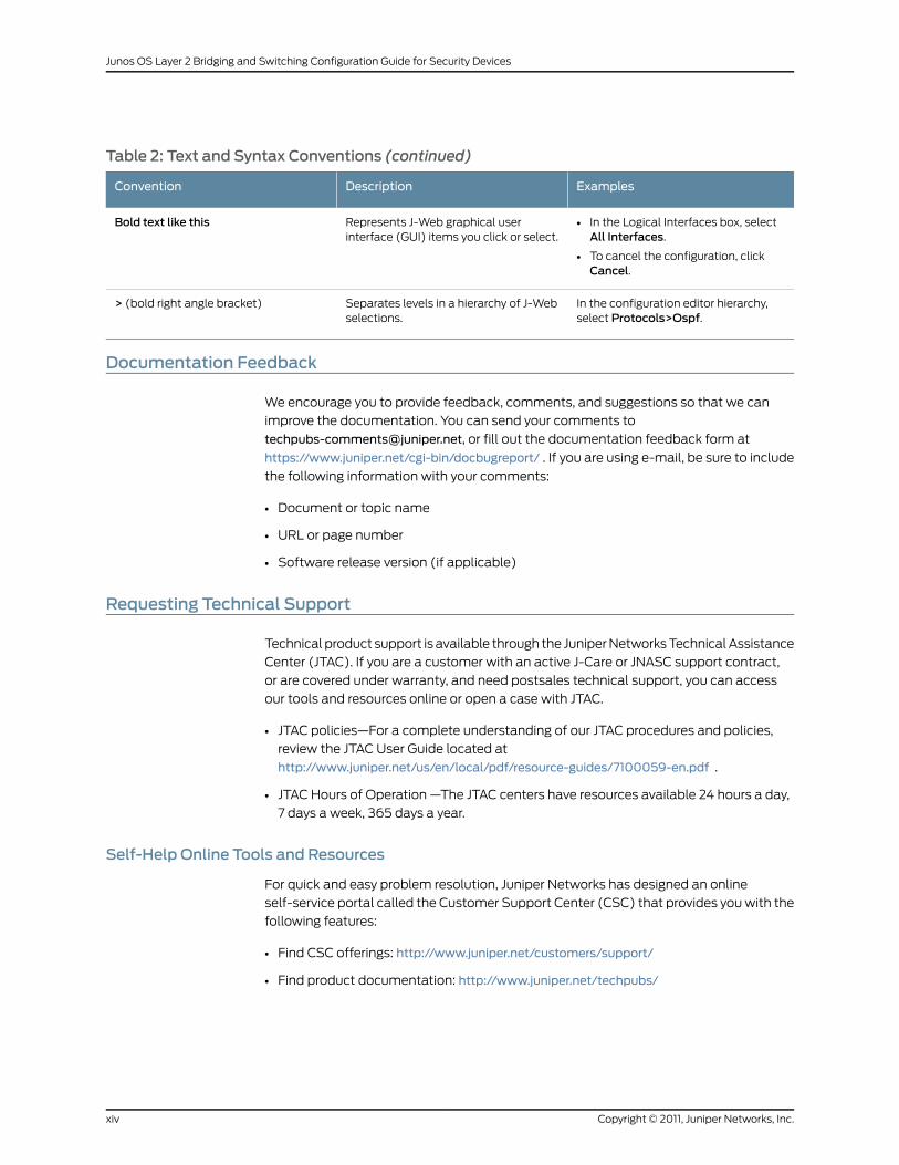
Table 2: Text and Syntax Conventions (continued)
ExamplesDescriptionConvention
• In the Logical Interfaces box, selectAll Interfaces.
• To cancel the configuration, clickCancel.
Represents J-Web graphical userinterface (GUI) items you click or select.
Bold text like this
In the configuration editor hierarchy,select Protocols>Ospf.
Separates levels in a hierarchy of J-Webselections.
> (bold right angle bracket)
Documentation Feedback
We encourage you to provide feedback, comments, and suggestions so that we can
improve the documentation. You can send your comments to
[email protected], or fill out the documentation feedback form at
https://www.juniper.net/cgi-bin/docbugreport/ . If you are using e-mail, be sure to include
the following information with your comments:
• Document or topic name
• URL or page number
• Software release version (if applicable)
Requesting Technical Support
Technical product support is available through the Juniper Networks Technical Assistance
Center (JTAC). If you are a customer with an active J-Care or JNASC support contract,
or are covered under warranty, and need postsales technical support, you can access
our tools and resources online or open a case with JTAC.
• JTAC policies—For a complete understanding of our JTAC procedures and policies,
review the JTAC User Guide located at
http://www.juniper.net/us/en/local/pdf/resource-guides/7100059-en.pdf .
• JTAC Hours of Operation —The JTAC centers have resources available 24 hours a day,
7 days a week, 365 days a year.
Self-Help Online Tools and Resources
For quick and easy problem resolution, Juniper Networks has designed an online
self-service portal called the Customer Support Center (CSC) that provides you with the
following features:
• Find CSC offerings: http://www.juniper.net/customers/support/
• Find product documentation: http://www.juniper.net/techpubs/
Copyright © 2011, Juniper Networks, Inc.xiv
Junos OS Layer 2 Bridging and Switching Configuration Guide for Security Devices
• Find solutions and answer questions using our Knowledge Base: http://kb.juniper.net/
• Download the latest versions of software and review release notes:
http://www.juniper.net/customers/csc/software/
• Search technical bulletins for relevant hardware and software notifications:
https://www.juniper.net/alerts/
• Join and participate in the Juniper Networks Community Forum:
http://www.juniper.net/company/communities/
• Open a case online in the CSC Case Management tool: http://www.juniper.net/cm/
To verify service entitlement by product serial number, use our Serial Number Entitlement
(SNE) Tool: https://tools.juniper.net/SerialNumberEntitlementSearch/
Opening a Casewith JTAC
You can open a case with JTAC on the Web or by telephone.
• Use the Case Management tool in the CSC at http://www.juniper.net/cm/ .
• Call 1-888-314-JTAC (1-888-314-5822 toll-free in the USA, Canada, and Mexico).
For international or direct-dial options in countries without toll-free numbers, visit us at
http://www.juniper.net/support/requesting-support.html
xvCopyright © 2011, Juniper Networks, Inc.
About This Guide

Copyright © 2011, Juniper Networks, Inc.xvi
Junos OS Layer 2 Bridging and Switching Configuration Guide for Security Devices
PART 1
Layer 2 Bridging and Switching
• Configuring Ethernet Ports for Switching on page 3
• Configuring Layer 2 Bridging and Transparent Mode on page 45
1Copyright © 2011, Juniper Networks, Inc.

Copyright © 2011, Juniper Networks, Inc.2
Junos OS Layer 2 Bridging and Switching Configuration Guide for Security Devices

CHAPTER 1
Configuring Ethernet Ports for Switching
• Ethernet Ports Switching Overview on page 3
• Switching Modes on page 8
• VLANs on page 10
• Spanning Tree Protocol on page 13
• Link Aggregation Control Protocol on page 18
• 802.1X Port-Based Network Authentication on page 23
• Port Security on page 35
• IGMP Snooping on page 39
• GARP VLAN Registration Protocol on page 42
Ethernet Ports Switching Overview
Certain ports on Juniper Networks devices can function as Ethernet access switches that
switch traffic at Layer 2 and route traffic at Layer 3.
You can deploy supported devices in branch offices as an access or desktop switch with
integrated routing capability, thus eliminating intermediate access switch devices from
your network topology. The Ethernet ports provide switching while the Routing Engine
provides routing functionality, enabling you to use a single device to provide routing,
access switching, and WAN interfaces.
This topic contains the following sections:
• Supported Devices and Ports on page 3
• Integrated Bridging and Routing on page 4
• Link Layer Discovery Protocol and LLDP-Media Endpoint Discovery on page 4
• Types of Switch Ports on page 6
• uPIM in a Daisy Chain on page 6
• Q-in-Q VLAN Tagging on page 7
Supported Devices and Ports
Juniper Networks supports switching features on the following Ethernet ports and devices
(see Table 3 on page 4):
3Copyright © 2011, Juniper Networks, Inc.

• Multiport Gigabit Ethernet uPIMs on the J Series device
• Onboard Ethernet ports (Gigabit and Fast Ethernet built-in ports) on the SRX100,
SRX210, and SRX240 devices
• Multiport Gigabit Ethernet XPIM on the SRX650 device
Table 3: Supported Devices and Ports for Switching Features
PortsDevice
Multiport Gigabit Ethernet uPIMsJ Series devices
Onboard Gigabit Ethernet ports (ge-0/0/0 through ge-0/0/15)SRX240 devices
Onboard Gigabit Ethernet ports (ge-0/0/0 and ge-0/0/1)
Onboard Fast Ethernet ports (fe-0/0/2 and fe-0/0/7)
SRX210 devices
Onboard Fast Ethernet ports (fe-0/0/0 and fe-0/0/7)SRX100 devices
Multiport Gigabit Ethernet XPIM modulesSRX650 devices
On J Series and SRX650 devices, you can set multiport switch modules (uPIMs and
XPIMs, respectively) to three modes of operation: routing (the default), switching, or
enhanced switching. Routed traffic is forwarded from any port of the Gigabit Ethernet
uPIM to the WAN interface. Switched traffic is forwarded from one port of the Gigabit
Ethernet uPIM to another port on the same Gigabit Ethernet uPIM. Switched traffic is not
forwarded from a port on one uPIM to a port on a different uPIM.
On the SRX100, SRX220, and SRX240 devices, you can set the onboard Gigabit Ethernet
ports to operate as either switched ports or routed ports.
Integrated Bridging and Routing
Integrated bridging and routing (IRB) provides support for simultaneous Layer 2 bridging
and Layer 3 routing within the same bridge domain. Packets arriving on an interface of
the bridge domain are switched or routed based on the destination MAC address of the
packet. Packets with the router’s MAC address as the destination are routed to other
Layer 3 interfaces.
Link Layer Discovery Protocol and LLDP-Media Endpoint Discovery
Devices use Link Layer Discovery Protocol (LLDP) and LLDP-Media Endpoint Discovery
(MFD) to learn and distribute device information on network links. The information allows
the device to quickly identify a variety of systems, resulting in a LAN that interoperates
smoothly and efficiently.
LLDP-capable devices transmit information in Type Length Value (TLV) messages to
neighbor devices. Device information can include specifics, such as chassis and port
identification and system name and system capabilities. The TLVs leverage this
information from parameters that have already been configured in the Junos OS.
Copyright © 2011, Juniper Networks, Inc.4
Junos OS Layer 2 Bridging and Switching Configuration Guide for Security Devices

LLDP-MED goes one step further, exchanging IP-telephony messages between the device
and the IP telephone. These TLV messages provide detailed information on Power over
Ethernet (PoE) policy. The PoE Management TLVs let the device ports advertise the
power level and power priority needed. For example, the device can compare the power
needed by an IP telephone running on a PoE interface with available resources. If the
device cannot meet the resources required by the IP telephone, the device could negotiate
with the telephone until a compromise on power is reached.
The following basic TLVs are supported:
• Chassis Identifier—The MAC address associated with the local system.
• Port identifier—The port identification for the specified port in the local system.
• Port Description—The user-configured port description. The port description can be a
maximum of 256 characters.
• System Name—The user-configured name of the local system. The system name can
be a maximum of 256 characters.
• Switching Features Overview—This information is not configurable, but taken from the
software.
• System Capabilities—The primary function performed by the system. The capabilities
that system supports; for example, bridge or router. This information is not configurable,
but based on the model of the product.
• Management Address—The IP management address of the local system.
The following LLDP-MED TLVs are supported:
• LLDP-MED Capabilities—A TLV that advertises the primary function of the port. The
values range from 0 through 15:
• 0—Capabilities
• 1—Network policy
• 2—Location identification
• 3—Extended power through medium-dependent interface power-sourcing equipment
(MDI-PSE)
• 4—Inventory
• 5–15—Reserved
• LLDP-MED Device Class Values:
• 0—Class not defined
• 1—Class 1 device
• 2—Class 2 device
• 3—Class 3 device
5Copyright © 2011, Juniper Networks, Inc.
Chapter 1: Configuring Ethernet Ports for Switching
• 4—Network connectivity device
• 5–255— Reserved
• Network Policy—A TLV that advertises the port VLAN configuration and associated
Layer 2 and Layer 3 attributes. Attributes include the policy identifier, application types,
such as voice or streaming video, 802.1Q VLAN tagging, and 802.1p priority bits and
Diffserv code points.
• Endpoint Location—A TLV that advertises the physical location of the endpoint.
• Extended Power via MDI—A TLV that advertises the power type, power source, power
priority, and power value of the port. It is the responsibility of the PSE device (network
connectivity device) to advertise the power priority on a port.
LLDP and LLDP-MED must be explicitly configured on uPIMs (in enhanced switching
mode) on J Series devices, base ports on SRX100, SRX210, and SRX240 devices, and
Gigabit Backplane Physical Interface Modules (GPIMs) on SRX650 devices. To configure
LLDP on all interfaces or on a specific interface, use the lldp statement at the [set
protocols] hierarchy. To configure LLDP-MED on all interfaces or on a specific interface,
use the lldp-med statement at the [set protocols] hierarchy.
Types of Switch Ports
The ports, or interfaces, on a switch operate in either access mode or trunk mode.
An interface in access mode connects to a network device, such as a desktop computer,
an IP telephone, a printer, a file server, or a security camera. The interface itself belongs
to a single VLAN. The frames transmitted over an access interface are normal Ethernet
frames.
Trunk interfaces handle traffic for multiple VLANs, multiplexing the traffic for all those
VLANs over the same physical connection. Trunk interfaces are generally used to
interconnect switches to one another.
uPIM in a Daisy Chain
You cannot combine multiple uPIMs to act as a single integrated switch. However, you
can connect uPIMs on the same chassis externally by physically connecting a port on
one uPIM to a port on another uPIM in a daisy-chain fashion.
Two or more uPIMs daisy-chained together create a single switch with a higher port count
than either individual uPIM. One port on each uPIM is used solely for the connection. For
example, if you daisy-chain a 6-port uPIM and an 8-port uPIM, the result operates as a
12-port uPIM. Any port of a uPIM can be used for daisy chaining.
Configure the IP address for only one of the daisy-chained uPIMs, making it the primary
uPIM. The secondary uPIM routes traffic to the primary uPIM, which forwards it to the
Routing Engine. This results in some increase in latency and packet drops due to
oversubscription of the external link.
Only one link between the two uPIMs is supported. Connecting more than one link between
uPIMs creates a loop topology, which is not supported.
Copyright © 2011, Juniper Networks, Inc.6
Junos OS Layer 2 Bridging and Switching Configuration Guide for Security Devices
Q-in-Q VLAN Tagging
Q-in-Q tunneling, defined by the IEEE 802.1ad standard, allows service providers on
Ethernet access networks to extend a Layer 2 Ethernet connection between two customer
sites.
In Q-in-Q tunneling, as a packet travels from a customer VLAN (C-VLAN) to a service
provider's VLAN, a service provider-specific 802.1Q tag is added to the packet. This
additional tag is used to segregate traffic into service-provider-defined service VLANs
(S-VLANs). The original customer 802.1Q tag of the packet remains and is transmitted
transparently, passing through the service provider's network. As the packet leaves the
S-VLAN in the downstream direction, the extra 802.1Q tag is removed.
NOTE: When Q-in-Q tunneling is configured for a service provider’s VLAN,allRoutingEnginepackets, includingpackets fromthe routedVLAN interface,that are transmitted from the customer-facing access port of that VLANwillalways be untagged.
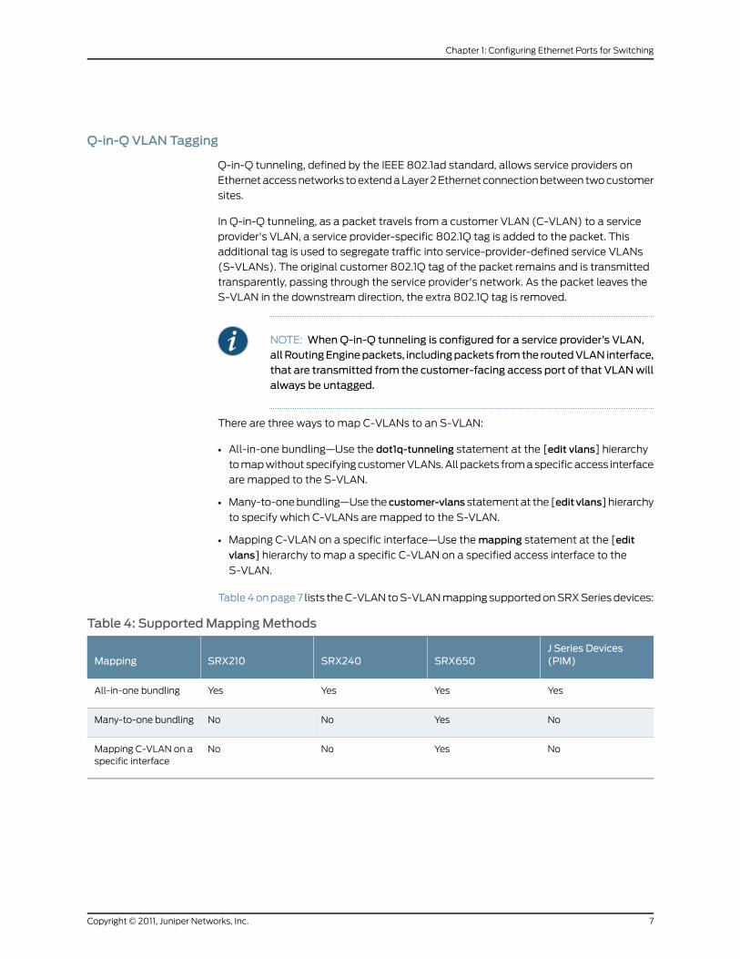
There are three ways to map C-VLANs to an S-VLAN:
• All-in-one bundling—Use the dot1q-tunneling statement at the [edit vlans] hierarchy
to map without specifying customer VLANs. All packets from a specific access interface
are mapped to the S-VLAN.
• Many-to-one bundling—Use the customer-vlans statement at the [editvlans] hierarchy
to specify which C-VLANs are mapped to the S-VLAN.
• Mapping C-VLAN on a specific interface—Use the mapping statement at the [edit
vlans] hierarchy to map a specific C-VLAN on a specified access interface to the
S-VLAN.
Table 4 on page 7 lists the C-VLAN to S-VLAN mapping supported on SRX Series devices:
Table 4: SupportedMappingMethods
J Series Devices(PIM)SRX650SRX240SRX210Mapping
YesYesYesYesAll-in-one bundling
NoYesNoNoMany-to-one bundling
NoYesNoNoMapping C-VLAN on aspecific interface
7Copyright © 2011, Juniper Networks, Inc.
Chapter 1: Configuring Ethernet Ports for Switching
NOTE: On SRX650 devices, in the dot1q-tunneling configuration options,customer VLANs range and VLAN push do not work together for the sameS-VLAN, even when you commit the configuration. If both are configured,then VLAN push takes priority over customer VLANs range.
IRB interfaces are supported on Q-in-Q VLANs for SRX210, SRX240, SRX650, and J Series
devices. Packets arriving on an IRB interface on a Q-in-Q VLAN are routed regardless of
whether the packet is single or double tagged. The outgoing routed packets contain an
S-VLAN tag only when exiting a trunk interface; the packets exit the interface untagged
when exiting an access interface.
In a Q-in-Q deployment, customer packets from downstream interfaces are transported
without any changes to source and destination MAC addresses. You can disable MAC
address learning at both the interface level and the VLAN level. Disabling MAC address
learning on an interface disables learning for all the VLANs of which that interface is a
member. When you disable MAC address learning on a VLAN, MAC addresses that have
already been learned are flushed.
RelatedDocumentation
Junos OS Feature Support Reference for SRX Series and J Series Devices•
• Junos OS Interfaces Configuration Guide for Security Devices
• Understanding Switching Modes on page 8
SwitchingModes
• Understanding Switching Modes on page 8
• Example: Configuring Switching Modes on page 8
• Verifying Switching Mode Configuration on page 9
Understanding SwitchingModes
You can set a multiport Gigabit Ethernet uPIM on a J Series device to either switching or
enhanced switching mode. The default mode of operation is routing mode.
When you set a multiport uPIM to switching mode, the uPIM appears as a single entity
for monitoring purposes. The only physical port settings that you can configure are
autonegotiation, speed, and duplex mode on each uPIM port, and these settings are
optional.
Example: Configuring SwitchingModes
This example shows how to configure a multiport Gigabit Ethernet uPIM to function in
switching mode so the uPIM appears as a single entity for monitoring purposes.
• Requirements on page 9
• Overview on page 9
Copyright © 2011, Juniper Networks, Inc.8
Junos OS Layer 2 Bridging and Switching Configuration Guide for Security Devices

• Configuration on page 9
• Verification on page 9
Requirements
Before you begin, see “Understanding Switching Modes” on page 8.
Overview
In this example, you configure chassis and set the uPIM mode of operation to switching.
You then set the uPIM mode of operation to enhanced switching. Finally, you configure
interface ge-2/0/0 and set the physical port parameter to auto-negotiation on switch
port 1 on the uPIM.
Configuration
Step-by-StepProcedure
To configure a uPIM to function in switching mode:
Set the uPIM mode of operation to switching.1.
[edit chassis fpc 0 pic 0 ethernet]user@host# set pic-mode switching
2. Set the uPIM mode of operation to enhanced switching.
[edit chassis fpc 0 pic 0 ethernet]user@host# set pic-mode enhanced-switching
3. Set a physical port parameter on the uPIM.
[edit]user@host# set interfaces ge-2/0/0 switch-options switch-port 1 auto-negotiation
4. If you are done configuring the device, commit the configuration.
[edit]user@host# commit
Verification
To verify the configuration is working properly, enter the show interfaces ge-2/0/0
switch-options and show chassis fpc 0 commands.
Verifying SwitchingMode Configuration
Purpose The operational mode command for checking the status and statistics for multiport
uPIMs in switching mode is different from that in routing mode. For uPIMs in routing mode,
the operational commands are the same as for other Gigabit Ethernet interfaces, such
as the 1-port Gigabit Ethernet ePIM and built-in Gigabit Ethernet ports.
However, not all operational mode commands are supported for ports of a uPIM in
switching mode. For example, the operational mode command for monitoring port
statistics is not supported.
9Copyright © 2011, Juniper Networks, Inc.
Chapter 1: Configuring Ethernet Ports for Switching
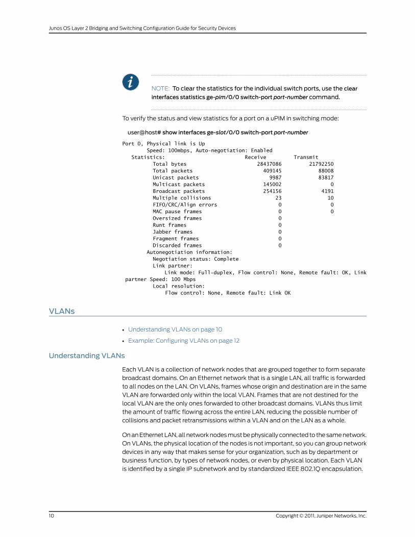
NOTE: To clear the statistics for the individual switch ports, use the clear
interfaces statistics ge-pim/0/0 switch-port port-number command.
To verify the status and view statistics for a port on a uPIM in switching mode:
user@host# show interfaces ge-slot/0/0 switch-port port-number
Port 0, Physical link is Up Speed: 100mbps, Auto-negotiation: Enabled Statistics: Receive Transmit Total bytes 28437086 21792250 Total packets 409145 88008 Unicast packets 9987 83817 Multicast packets 145002 0 Broadcast packets 254156 4191 Multiple collisions 23 10 FIFO/CRC/Align errors 0 0 MAC pause frames 0 0 Oversized frames 0 Runt frames 0 Jabber frames 0 Fragment frames 0 Discarded frames 0 Autonegotiation information: Negotiation status: Complete Link partner: Link mode: Full-duplex, Flow control: None, Remote fault: OK, Link partner Speed: 100 Mbps Local resolution: Flow control: None, Remote fault: Link OK
VLANs
• Understanding VLANs on page 10
• Example: Configuring VLANs on page 12
Understanding VLANs
Each VLAN is a collection of network nodes that are grouped together to form separate
broadcast domains. On an Ethernet network that is a single LAN, all traffic is forwarded
to all nodes on the LAN. On VLANs, frames whose origin and destination are in the same
VLAN are forwarded only within the local VLAN. Frames that are not destined for the
local VLAN are the only ones forwarded to other broadcast domains. VLANs thus limit
the amount of traffic flowing across the entire LAN, reducing the possible number of
collisions and packet retransmissions within a VLAN and on the LAN as a whole.
On an Ethernet LAN, all network nodes must be physically connected to the same network.
On VLANs, the physical location of the nodes is not important, so you can group network
devices in any way that makes sense for your organization, such as by department or
business function, by types of network nodes, or even by physical location. Each VLAN
is identified by a single IP subnetwork and by standardized IEEE 802.1Q encapsulation.
Copyright © 2011, Juniper Networks, Inc.10
Junos OS Layer 2 Bridging and Switching Configuration Guide for Security Devices
To identify which VLAN the traffic belongs to, all frames on an Ethernet VLAN are identified
by a tag, as defined in the IEEE 802.1Q standard. These frames are tagged and are
encapsulated with 802.1Q tags.
For a simple network that has only a single VLAN, all traffic has the same 802.1Q tag.
When an Ethernet LAN is divided into VLANs, each VLAN is identified by a unique 802.1Q
tag. The tag is applied to all frames so that the network nodes receiving the frames know
to which VLAN a frame belongs. Trunk ports, which multiplex traffic among a number of
VLANs, use the tag to determine the origin of frames and where to forward them.
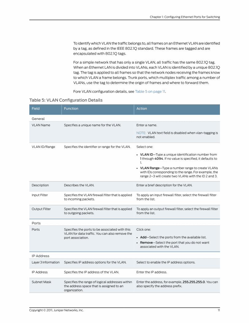
Fore VLAN configuration details, see Table 5 on page 11.
Table 5: VLAN Configuration Details
ActionFunctionField
General
Enter a name.
NOTE: VLAN text field is disabled when vlan-tagging isnot enabled.
Specifies a unique name for the VLAN.VLAN Name
Select one:
• VLAN ID—Type a unique identification number from1 through 4094. If no value is specified, it defaults to1.
• VLANRange—Type a number range to create VLANswith IDs corresponding to the range. For example, therange 2–3 will create two VLANs with the ID 2 and 3.
Specifies the identifier or range for the VLAN.VLAN ID/Range
Enter a brief description for the VLAN.Describes the VLAN.Description
To apply an input firewall filter, select the firewall filterfrom the list.
Specifies the VLAN firewall filter that is appliedto incoming packets.
Input Filter
To apply an output firewall filter, select the firewall filterfrom the list.
Specifies the VLAN firewall filter that is appliedto outgoing packets.
Output Filter
Ports
Click one:
• Add—Select the ports from the available list.
• Remove—Select the port that you do not wantassociated with the VLAN.
Specifies the ports to be associated with thisVLAN for data traffic. You can also remove theport association.
Ports
IP Address
Select to enable the IP address options.Specifies IP address options for the VLAN.Layer 3 Information
Enter the IP address.Specifies the IP address of the VLAN.IP Address
Enter the address, for example, 255.255.255.0. You canalso specify the address prefix.
Specifies the range of logical addresses withinthe address space that is assigned to anorganization.
Subnet Mask
11Copyright © 2011, Juniper Networks, Inc.
Chapter 1: Configuring Ethernet Ports for Switching

Table 5: VLAN Configuration Details (continued)
ActionFunctionField
To apply an input firewall filter to an interface, selectthe firewall filter from the list.
Specifies the VLAN interface firewall filter thatis applied to incoming packets.
Input Filter
To apply an output firewall filter to an interface, selectthe firewall filter from the list.
Specifies the VLAN interface firewall filter thatis applied to outgoing packets.
Output Filter
Click the ARP/MACDetails button. Enter the static IPaddress and MAC address in the window that isdisplayed.
Specifies the details for configuring the staticIP address and MAC.
ARP/MAC Details
VoIP
Click one:
• Add—Select the ports from the available list.
• Remove—Select the port that you do not wantassociated with the VLAN.
Specifies the ports to be associated with thisVLAN for voice traffic. You can also remove theport association.
Ports
RelatedDocumentation
Junos OS Feature Support Reference for SRX Series and J Series Devices•
• Example: Configuring VLANs on page 12
• Ethernet Ports Switching Overview on page 3
• Verifying Switching Mode Configuration on page 9
Example: Configuring VLANs
This example shows you how to configure a VLAN.
Requirements
Before you begin:
• Determine which interfaces to use and verify that they are in switch mode. See
“Example: Configuring Switching Modes” on page 8.
• Determine what ports to use on the device and how to segment your network. See
“Understanding Switching Modes” on page 8.
Overview
In this example, you create a new VLAN and then configure attributes.
Configuration
GUI Step-by-StepProcedure
To access the VLAN:
In the J-Web user interface, select Configure>Switching>VLAN.1.
The VLAN configuration page displays a list of existing VLANs. If you select a specific
VLAN, the specific VLAN details are displayed in the details section.
Copyright © 2011, Juniper Networks, Inc.12
Junos OS Layer 2 Bridging and Switching Configuration Guide for Security Devices
2. Click one:
• Add—Creates a VLAN.
• Edit—Edits an existing VLAN configuration.
• Delete—Deletes an existing VLAN.
NOTE: If you delete a VLAN, the VLAN configuration for all theassociated interfaces is also deleted.
Add or edit VLAN information.
3. Click one:
• OK—Saves the configuration and returns to the main configuration page, then click
Commit Options>Commit.
• Cancel—Cancels your entries and returns to the main configuration page.
RelatedDocumentation
Junos OS Feature Support Reference for SRX Series and J Series Devices•
• Understanding VLANs on page 10
• Ethernet Ports Switching Overview on page 3
• Verifying Switching Mode Configuration on page 9
Spanning Tree Protocol
• Understanding the Spanning Tree Protocol on page 13
• Configuring the Spanning Tree Protocol on page 17
Understanding the Spanning Tree Protocol
Spanning Tree Protocol (STP), defined in IEEE 802.1D, creates a tree of links in the
Ethernet switched network. Links that cause loops in the network are disabled, thereby
providing a single active link between any two switches.
Rapid Spanning Tree Protocol (RSTP), originally defined in IEEE 802.1w and later merged
into IEEE 802.1D, facilitates faster spanning tree convergence after a topology change.
Multiple Spanning Tree Protocol (MSTP), initially defined in IEEE 802.1s and later included
in IEEE 802.1Q, supports mapping of multiple VLANs onto a single spanning tree instance.
This reduces the number of spanning tree instances required in a switched network with
many VLANs.
Juniper Networks devices provide Layer 2 loop prevention through STP, RSTP, and MSTP.
You can configure bridge protocols data unit (BPDU) protection on interfaces to prevent
them from receiving BPDUs that could result in STP misconfigurations, which could lead
to network outages.
13Copyright © 2011, Juniper Networks, Inc.
Chapter 1: Configuring Ethernet Ports for Switching
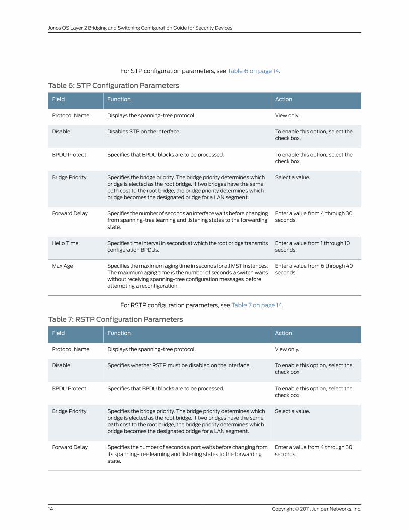
For STP configuration parameters, see Table 6 on page 14.
Table 6: STP Configuration Parameters
ActionFunctionField
View only.Displays the spanning-tree protocol.Protocol Name
To enable this option, select thecheck box.
Disables STP on the interface.Disable
To enable this option, select thecheck box.
Specifies that BPDU blocks are to be processed.BPDU Protect
Select a value.Specifies the bridge priority. The bridge priority determines whichbridge is elected as the root bridge. If two bridges have the samepath cost to the root bridge, the bridge priority determines whichbridge becomes the designated bridge for a LAN segment.
Bridge Priority
Enter a value from 4 through 30seconds.
Specifies the number of seconds an interface waits before changingfrom spanning-tree learning and listening states to the forwardingstate.
Forward Delay
Enter a value from 1 through 10seconds.
Specifies time interval in seconds at which the root bridge transmitsconfiguration BPDUs.
Hello Time
Enter a value from 6 through 40seconds.
Specifies the maximum aging time in seconds for all MST instances.The maximum aging time is the number of seconds a switch waitswithout receiving spanning-tree configuration messages beforeattempting a reconfiguration.
Max Age
For RSTP configuration parameters, see Table 7 on page 14.
Table 7: RSTP Configuration Parameters
ActionFunctionField
View only.Displays the spanning-tree protocol.Protocol Name
To enable this option, select thecheck box.
Specifies whether RSTP must be disabled on the interface.Disable
To enable this option, select thecheck box.
Specifies that BPDU blocks are to be processed.BPDU Protect
Select a value.Specifies the bridge priority. The bridge priority determines whichbridge is elected as the root bridge. If two bridges have the samepath cost to the root bridge, the bridge priority determines whichbridge becomes the designated bridge for a LAN segment.
Bridge Priority
Enter a value from 4 through 30seconds.
Specifies the number of seconds a port waits before changing fromits spanning-tree learning and listening states to the forwardingstate.
Forward Delay
Copyright © 2011, Juniper Networks, Inc.14
Junos OS Layer 2 Bridging and Switching Configuration Guide for Security Devices

Table 7: RSTP Configuration Parameters (continued)
ActionFunctionField
Enter a value from 1 through 10seconds.
Specifies the hello time in seconds for all MST instances.Hello Time
Enter a value from 6 through 40seconds.
Specifies the maximum aging time in seconds for all MST instances.The maximum aging time is the number of seconds a switch waitswithout receiving spanning-tree configuration messages beforeattempting a reconfiguration.
Max Age
For MSTP configuration parameters, see Table 8 on page 15.
Table 8: MSTP Configuration Parameters
ActionFunctionField
View only.Displays the spanning-tree protocol.Protocol Name
To enable this option, select the checkbox.
Specifies whether MSTP must be disabled on the interface.Disable
To enable this option, select the checkbox.
Specifies that BPDU blocks are to be processed.BPDU Protect
Select a value.Specifies the bridge priority. The bridge priority determineswhich bridge is elected as the root bridge. If two bridges havethe same path cost to the root bridge, the bridge prioritydetermines which bridge becomes the designated bridge fora LAN segment.
Bridge Priority
Enter a value from 4 through 30seconds.
Specifies the number of seconds a port waits before changingfrom its spanning-tree learning and listening states to theforwarding state.
Forward Delay
Enter a value from 1 through 10 seconds.Specifies the hello time in seconds for all MST instances.Hello Time
Enter a value from 6 through 40seconds.
Specifies the maximum aging time for all MST instances. Themaximum aging time is the number of seconds a switch waitswithout receiving spanning-tree configuration messages beforeattempting a reconfiguration.
Max Age
Enter a name.MSTP region name carried in the MSTP bridge protocol dataunits (BPDUs).
ConfigurationName
Enter a value from 1 through 255.Maximum number of hops a BPDU can be forwarded in theMSTP region.
Max Hops
Enter a value from 0 through 65,535.Revision number of the MSTP region configuration.Revision Level
MSTI tab
15Copyright © 2011, Juniper Networks, Inc.
Chapter 1: Configuring Ethernet Ports for Switching

Table 8: MSTP Configuration Parameters (continued)
ActionFunctionField
Click one:
• Add—Creates a MSTI.
• Edit—Edits an existing MSTI.
• Delete—Deletes an existing MSTI.
Specifies the multiple spanning-tree instance (MSTI) identifier.MSTI IDs are local to each region, so you can reuse the sameMSTI ID in different regions.
MSTI Id
Select a value.Specifies the bridge priority. The bridge priority determineswhich bridge is elected as the root bridge. If two bridges havethe same path cost to the root bridge, the bridge prioritydetermines which bridge becomes the designated bridge fora LAN segment.
Bridge Priority
Click one:
• Add—Selects VLANs from the list.
• Remove—Deletes the selected VLAN.
Specifies the VLANs for the MSTI.VLAN
Click one:
• Add—Selects interfaces from the list.
• Edit—Edits the selected interface.
• Remove—Deletes the selectedinterface.
Specifies the interface for the MSTP protocol.Interfaces
For spanning-tree port configuration details, see Table 9 on page 16.
Table 9: Spanning-Tree Ports Configuration Details
ActionFunctionField
Select an interface.Specifies the interface for thespanning-tree protocol type.
Interface Name
Enter a value from 1 through200,000,000.
Specifies the link cost to control whichbridge is the designated bridge and whichinterface is the designated interface.
Cost
Select a value.Specifies the interface priority to controlwhich interface is elected as the rootport.
Priority
Select to configure the interface as anedge interface.
Configures the interface as an edgeinterface. Edge interfaces immediatelytransition to a forwarding state.
Edge
Select one:
• Point to Point—For full-duplex links,select this mode.
• Shared—For half-duplex links, selectthis mode.
Specifies the link mode.Mode
Copyright © 2011, Juniper Networks, Inc.16
Junos OS Layer 2 Bridging and Switching Configuration Guide for Security Devices

RelatedDocumentation
Junos OS Feature Support Reference for SRX Series and J Series Devices•
• Configuring the Spanning Tree Protocol on page 17
• Ethernet Ports Switching Overview on page 3
• Verifying Switching Mode Configuration on page 9
Configuring the Spanning Tree Protocol
This example shows you how to configure the Spanning Tree Protocol on a Ethernet
switched network.
Requirements
Before you begin:
• Determine which interfaces to use and verify that they are in switch mode. See
“Example: Configuring Switching Modes” on page 8.
• Review information about switching modes. See “Understanding Switching Modes”
on page 8.
Overview
In this example, you enable the Spanning Tree Protocol on switched Ethernet ports.
Configuration
GUI Step-by-StepProcedure
To access the Spanning Tree Quick Configuration:
In the J-Web user interface, select Configure>Switching>Spanning Tree.1.
The Spanning Tree Configuration page displays a list of existing spanning trees. If you
select a specific spanning tree, the specific spanning tree details are displayed in the
General and Interfaces tabs.
2. Click one of the following:
• Add—Creates a spanning tree.
• Edit—Edits an existing spanning-tree configuration.
• Delete—Deletes an existing spanning tree.
When you are adding a spanning tree, select a protocol name: STP, RSTP, or MSTP.
Select the Ports tab to configure the ports associated with this spanning tree. Click
one of the following:
• Add—Creates a new spanning-tree interface configuration.
• Edit—Modifies an existing spanning-tree interface configuration.
• Delete—Deletes an existing spanning-tree interface configuration.
17Copyright © 2011, Juniper Networks, Inc.
Chapter 1: Configuring Ethernet Ports for Switching
When you are adding or editing a spanning-tree port, enter information describing the
port.
3. Click one:
• Click OK to check your configuration and save it as a candidate configuration, then
click Commit Options>Commit.
• Click Cancel to cancel the configuration without saving changes.
RelatedDocumentation
Junos OS Feature Support Reference for SRX Series and J Series Devices•
• Understanding the Spanning Tree Protocol on page 13
• Ethernet Ports Switching Overview on page 3
• Verifying Switching Mode Configuration on page 9
Link Aggregation Control Protocol
• Understanding Link Aggregation Control Protocol on page 18
• Example: Configuring Link Aggregation Control Protocol on page 21
Understanding Link Aggregation Control Protocol
LACP, a subcomponent of IEEE 802.3ad, provides additional functionality for link
aggregation groups (LAGs). Use the link aggregation feature to aggregate one or more
Ethernet interfaces to form to form a logical point-to-point link, known as a LAG, virtual
link, or bundle. The MAC client can treat this virtual link like a single link.
This topic contains the following sections:
• Link Aggregation Benefits on page 18
• Link Aggregation Configuration Guidelines on page 19
Link Aggregation Benefits
Link aggregation increases bandwidth, provides graceful degradation as failure occurs,
and increases availability. It provides network redundancy by load-balancing traffic across
all available links. If one of the links should fail, the system automatically load-balances
traffic across all remaining links.
When LACP is not enabled, a local LAG might attempt to transmit packets to a remote
single interface, which causes the communication to fail. When LACP is enabled, a local
LAG cannot transmit packets unless a LAG with LACP is also configured on the remote
end of the link.
A typical LAG deployment includes aggregate trunk links between an access switch and
a distribution switch or customer edge (CE) device.
Copyright © 2011, Juniper Networks, Inc.18
Junos OS Layer 2 Bridging and Switching Configuration Guide for Security Devices
Link Aggregation Configuration Guidelines
When configuring link aggregation, note the following guidelines and restrictions:
• Link aggregation is supported only for Ethernet interfaces that are configured in
switching mode (familyethernet-switching). Aggregating interfaces that are configured
in routed mode (family inet) is not supported.
• You can configure a LAG by specifying the link number as a physical device and then
associating a set of ports with the link. All the ports must have the same speed and be
in full-duplex mode. Junos OS assigns a unique ID and port priority to each port. The
ID and priority are not configurable.
• You must enable LACP when you configure a LAG.
• You can create up to eight Ethernet ports in each bundle.
• Each LAG must be configured on both sides of the link. The ports on either side of the
link must be set to the same speed. At least one end of the LAG should be configured
as active.
• LAGs are not supported on virtual chassis port links.
• By default, Ethernet links do not exchange protocol data units (PDUs), which contain
information about the state of the link. You can configure Ethernet links to actively
transmit PDUs, or you can configure the links to passively transmit them, sending out
LACP PDUs only when they receive them from another link. The transmitting link is
known as the actor and the receiving link is known as the partner.
• LAGs can only be used for a point-to-point connection.
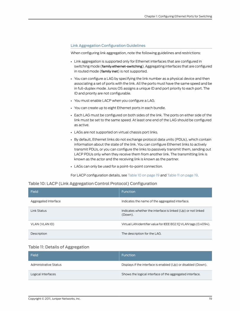
For LACP configuration details, see Table 10 on page 19 and Table 11 on page 19.
Table 10: LACP (Link Aggregation Control Protocol) Configuration
FunctionField
Indicates the name of the aggregated interface.Aggregated Interface
Indicates whether the interface is linked (Up) or not linked(Down).
Link Status
Virtual LAN identifier value for IEEE 802.1Q VLAN tags (0.4094).VLAN (VLAN ID)
The description for the LAG.Description
Table 11: Details of Aggregation
FunctionField
Displays if the interface is enabled (Up) or disabled (Down).Administrative Status
Shows the logical interface of the aggregated interface.Logical Interfaces
19Copyright © 2011, Juniper Networks, Inc.
Chapter 1: Configuring Ethernet Ports for Switching

Table 11: Details of Aggregation (continued)
FunctionField
Member interfaces hold all the aggregated interfaces of theselected interfaces.
Member Interfaces
Specifies the mode of operation for the port: trunk or access.Port Mode
VLAN identifier to associate with untagged packets receivedon the interface.
Native VLAN (VLAN ID)
Specifies the address of the aggregated interfaces.IP Address/Subnet Mask
Specifies the IPV6 address of the aggregated interfaces.IPV6 Address/Subnet Mask
For aggregated Ethernet interface options, see Table 12 on page 20.
Table 12: Aggregated Ethernet Interface Options
ActionFunctionField
Enter the aggregated interface name. Ifan aggregated interface already exists,then the field is displayed as read-only.
Indicates the name of the aggregatedinterface.
Aggregated Interface
Select from the list.Specifies the mode in which LACPpackets are exchanged between theinterfaces. The modes are:
• None—Indicates that no mode isapplicable.
• Active—Indicates that the interfaceinitiates transmission of LACP packets
• Passive—Indicates that the interfaceonly responds to LACP packets.
LACP Mode
Enter the description.The description for the LAG.Description
Click Add to select the interfaces.
NOTE: Only interfaces that areconfigured with the same speeds can beselected together for a LAG.
Indicates that the interfaces available foraggregation.
Interface
Indicates the speed of the interface.Speed
Select to enable log generation.Specifies whether to enable generationof log entries for LAG.
Enable Log
Copyright © 2011, Juniper Networks, Inc.20
Junos OS Layer 2 Bridging and Switching Configuration Guide for Security Devices

NOTE: On SRX100, SRX110, SRX120, SRX210, SRX220, SRX240, SRX650,and J Series devices, the speedmode and link mode configuration areavailable for member interfaces of ae.
For VLAN options, see Table 13 on page 21.
Table 13: Edit VLANOptions
ActionFunctionField
If you select Trunk, you can:
1. Click Add to add a VLAN member.
2. Select the VLAN and click OK.
3. (Optional) Associate a native VLANID with the port.
If you select Access, you can:
1. Select the VLAN member to beassociated with the port.
2. (Optional) Associate a VoIP VLANwith the interface. Only a VLAN witha VLAN ID can be associated as aVoIP VLAN.
3. Click OK.
Specifies the mode of operation for theport: trunk or access.
Port Mode
Click Add to select VLAN members.For trunk interfaces, the VLANs for whichthe interface can carry traffic.
VLAN Options
Select the VLAN identifier.VLAN identifier to associate withuntagged packets received on theinterface.
Native VLAN
RelatedDocumentation
Junos OS Feature Support Reference for SRX Series and J Series Devices•
• Example: Configuring Link Aggregation Control Protocol on page 21
• Ethernet Ports Switching Overview on page 3
• Verifying Switching Mode Configuration on page 9
Example: Configuring Link Aggregation Control Protocol
This example shows how to configure LACP.
Requirements
Before you begin:
• Verify that the Ethernet interfaces are in switch mode. See “Example: Configuring
Switching Modes” on page 8.
21Copyright © 2011, Juniper Networks, Inc.
Chapter 1: Configuring Ethernet Ports for Switching
• Link aggregation of one or more interfaces must be set up to form a virtual link or link
aggregation group (LAG) before you can apply LACP. See “Understanding Switching
Modes” on page 8.
Overview
In this example, you configure link aggregation for switched Ethernet interfaces then
apply LACP.
Configuration
GUI Step-by-StepProcedure
To access the LACP Configuration:
In the J-Web user interface, select Configure>Interfaces>Link Aggregation.1.
The Aggregated Interfaces list is displayed.
2. Click one of the following:
• Device Count—Creates an aggregated Ethernet interface, or LAG. You can choose
the number of device that you want to create.
• Add—Adds a new aggregated Ethernet Interface, or LAG.
• Edit— Modifies a selected LAG
• Aggregation—Modifies an selected LAG.
• VLAN—Specifies VLAN options for the selected LAG.
• IP Option—Configuring IP address to LAG is not supported and when you try to
configure the IP address an error message is displayed.
• Delete—Deletes the selected LAG.
• Disable Port or Enable Port—Disables or enables the administrative status on the
selected interface.
3. Click one:
• Click OK to check your configuration and save it as a candidate configuration, then
click Commit Options>Commit.
• Click Cancel to cancel the configuration without saving changes.
RelatedDocumentation
Junos OS Feature Support Reference for SRX Series and J Series Devices•
• Understanding Link Aggregation Control Protocol on page 18
• Ethernet Ports Switching Overview on page 3
• Verifying Switching Mode Configuration on page 9
Copyright © 2011, Juniper Networks, Inc.22
Junos OS Layer 2 Bridging and Switching Configuration Guide for Security Devices
802.1X Port-Based Network Authentication
• Understanding 802.1X Port-Based Network Authentication on page 23
• Example: Configuring 802.1x Authentication on page 28
• Example: Specifying RADIUS Server Connections on the Device on page 29
• Example: Configuring 802.1x Interface Settings on page 32
• Example: Configuring a Guest VLAN on page 34
Understanding 802.1X Port-Based Network Authentication
IEEE 802.1X and MAC RADIUS authentication both provide network edge security,
protecting Ethernet LANs from unauthorized user access by blocking all traffic to and
from devices at the interface until the supplicant's credential or MAC address is presented
and matched on the authentication server (a RADIUS server). When the supplicant is
authenticated, the switch stops blocking access and opens the interface to the supplicant.
A LAN network configured for 802.1X authentication contains three basic components:
• Supplicant—The IEEE term for a host that requests to join the network. The host can
be responsive or nonresponsive. A responsive host is one on which 802.1X authentication
is enabled and that provides authentication credentials (such as a user name and
password). A nonresponsive host is one on which 802.1X authentication is not enabled.
• Authenticator Port Access Entity—The IEEE term for the authenticator. The SRX Series
or J Series device is the authenticator and controls access by blocking all traffic to and
from supplicants until they are authenticated.
• Authentication server—The server containing the back-end database that makes
authentication decisions. (Junos OS supports RADIUS authentication servers.) The
authentication server contains credential information for each supplicant that can
connect to the network. The authenticator forwards credentials supplied by the
supplicant to the authentication server. If the credentials forwarded by the authenticator
match the credentials in the authentication server database, access is granted. If the
credentials forwarded do not match, access is denied.
NOTE: Change of authorization (CoA) is not supported on SRX100, SRX210,SRX240, SRX650, and J Series devices.
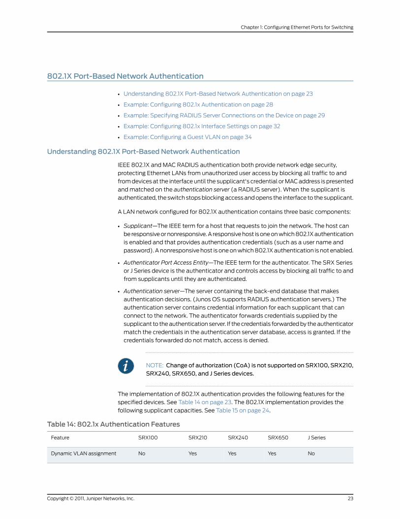
The implementation of 802.1X authentication provides the following features for the
specified devices. See Table 14 on page 23. The 802.1X implementation provides the
following supplicant capacities. See Table 15 on page 24.
Table 14: 802.1x Authentication Features
J SeriesSRX650SRX240SRX210SRX100Feature
NoYesYesYesNoDynamic VLAN assignment
23Copyright © 2011, Juniper Networks, Inc.
Chapter 1: Configuring Ethernet Ports for Switching

Table 14: 802.1x Authentication Features (continued)
NoYesYesYesYesMAC RADIUS authentication
Yes (withoutVLAN option)
YesYesYesYes (withoutVLAN option)
Static MAC bypass
NoYesYesYesNoGuest VLAN
NoYesYesYesNoRADIUS server failure fallback
NoYesYesYesNoVoIP VLAN support
NoYesYesYesYesRADIUS accounting
Table 15: 802.1x Supplicant Capacities
J SeriesSRX650SRX240SRX210SRX100
6464646464Supplicants per port
2K2K2K2K2KSupplicants per system
Not supported2K30064Not supportedSupplicants with dynamic VLANassignments
This topic contains the following sections:
• Dynamic VLAN Assignment on page 24
• MAC RADIUS Authentication on page 25
• Static MAC Bypass on page 25
• Guest VLAN on page 25
• RADIUS Server Failure Fallback on page 25
• VoIP VLAN Support on page 27
• RADIUS Accounting on page 28
• Server Reject VLAN on page 28
Dynamic VLANAssignment
When a supplicant first connects to an SRX Series or J Series device, the authenticator
sends a request to the supplicant to begin 802.1X authentication. If the supplicant is an
802.1X-enabled device, it responds, and the authenticator relays an authentication
request to the RADIUS server.
As part of the reply to the authentication request, the RADIUS server returns information
about the VLAN to which the port belongs. By configuring the VLAN information at the
RADIUS server, you can control the VLAN assignment on the port.
Copyright © 2011, Juniper Networks, Inc.24
Junos OS Layer 2 Bridging and Switching Configuration Guide for Security Devices
MACRADIUS Authentication
If the authenticator sends three requests to a supplicant to begin 802.1X authentication
and receives no response, the supplicant is considered nonresponsive. For a nonresponsive
supplicant, the authenticator sends a request to the RADIUS server for authentication
of the supplicant’s MAC address. If the MAC address matches an entry in a predefined
list of MAC addresses on the RADIUS server, authentication is granted and the
authenticator opens LAN access on the interface where the supplicant is connected.
You can configure the number of times the authenticator attempts to receive a response
and the time period between attempts.
Static MAC Bypass
The authenticator can allow particular supplicants direct access to the LAN and bypass
the authentication server by including the supplicants’ MAC addresses in the static MAC
bypass list configured on the SRX Series or J Series device. This list is checked first. If a
match is found, the supplicant is considered successfully authenticated and the interface
is opened up for it. No further authentication is done for that supplicant. If a match is not
found and 802.1X authentication is enabled for the supplicant, the device continues with
MAC RADIUS authentication on the authentication server.
For each MAC address in the list, you can configure the VLAN to which the supplicant is
moved or the interfaces on which the supplicant can connect.
Guest VLAN
You can specify a guest VLAN that provides limited network access for nonresponsive
supplicants. If a guest-vlan is configured, the authenticator connects all nonresponsive
supplicants to the predetermined VLAN, providing limited network access, often only to
the Internet. This type of configuration can be used to provide Internet access to visitors
without compromising company security.
NOTE: In 802.1x, mac-radius and guest-vlan should not be configuredtogether, because guest-vlan does not work whenmac-radius is configured.
IEEE 802.1X provides LAN access to nonresponsive hosts, which are hosts where 802.1X
is not enabled. These hosts, referred to as guests, typically are provided access only to
the Internet.
RADIUS Server Failure Fallback
You can define one of four actions to be taken if no RADIUS authentication server is
reachable (if, for example, a server failure or a timeout has occurred on the authentication
server).
• deny—(default) Prevent traffic from flowing from the supplicant through the interface.
• permit—Allow traffic to flow from the supplicant through the interface as if the
supplicant were successfully authenticated by the RADIUS server.
25Copyright © 2011, Juniper Networks, Inc.
Chapter 1: Configuring Ethernet Ports for Switching
• use-cache—Force successful authentication if authentication was granted before the
failure or timeout. This ensures that authenticated users are not adversely affected by
a failure or timeout.
• vlan vlan-name | vlan-id—Move the supplicant to a different VLAN specified by name
or ID. This applies only to the first supplicant connecting to the interface.
NOTE: For permit, use-cache, and vlan fallback actions to work, 802.1Xsupplicants need to accept an out of sequence SUCCESS packet.
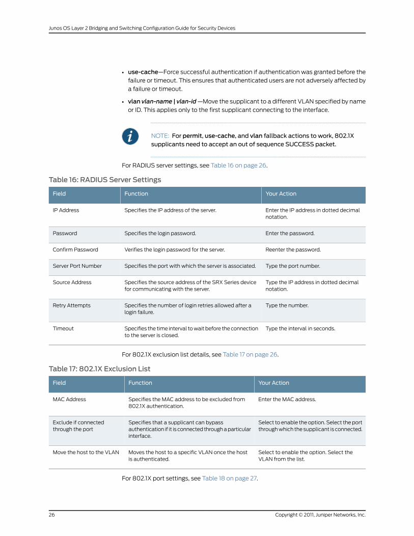
For RADIUS server settings, see Table 16 on page 26.
Table 16: RADIUS Server Settings
Your ActionFunctionField
Enter the IP address in dotted decimalnotation.
Specifies the IP address of the server.IP Address
Enter the password.Specifies the login password.Password
Reenter the password.Verifies the login password for the server.Confirm Password
Type the port number.Specifies the port with which the server is associated.Server Port Number
Type the IP address in dotted decimalnotation.
Specifies the source address of the SRX Series devicefor communicating with the server.
Source Address
Type the number.Specifies the number of login retries allowed after alogin failure.
Retry Attempts
Type the interval in seconds.Specifies the time interval to wait before the connectionto the server is closed.
Timeout
For 802.1X exclusion list details, see Table 17 on page 26.
Table 17: 802.1X Exclusion List
Your ActionFunctionField
Enter the MAC address.Specifies the MAC address to be excluded from802.1X authentication.
MAC Address
Select to enable the option. Select the portthrough which the supplicant is connected.
Specifies that a supplicant can bypassauthentication if it is connected through a particularinterface.
Exclude if connectedthrough the port
Select to enable the option. Select theVLAN from the list.
Moves the host to a specific VLAN once the hostis authenticated.
Move the host to the VLAN
For 802.1X port settings, see Table 18 on page 27.
Copyright © 2011, Juniper Networks, Inc.26
Junos OS Layer 2 Bridging and Switching Configuration Guide for Security Devices
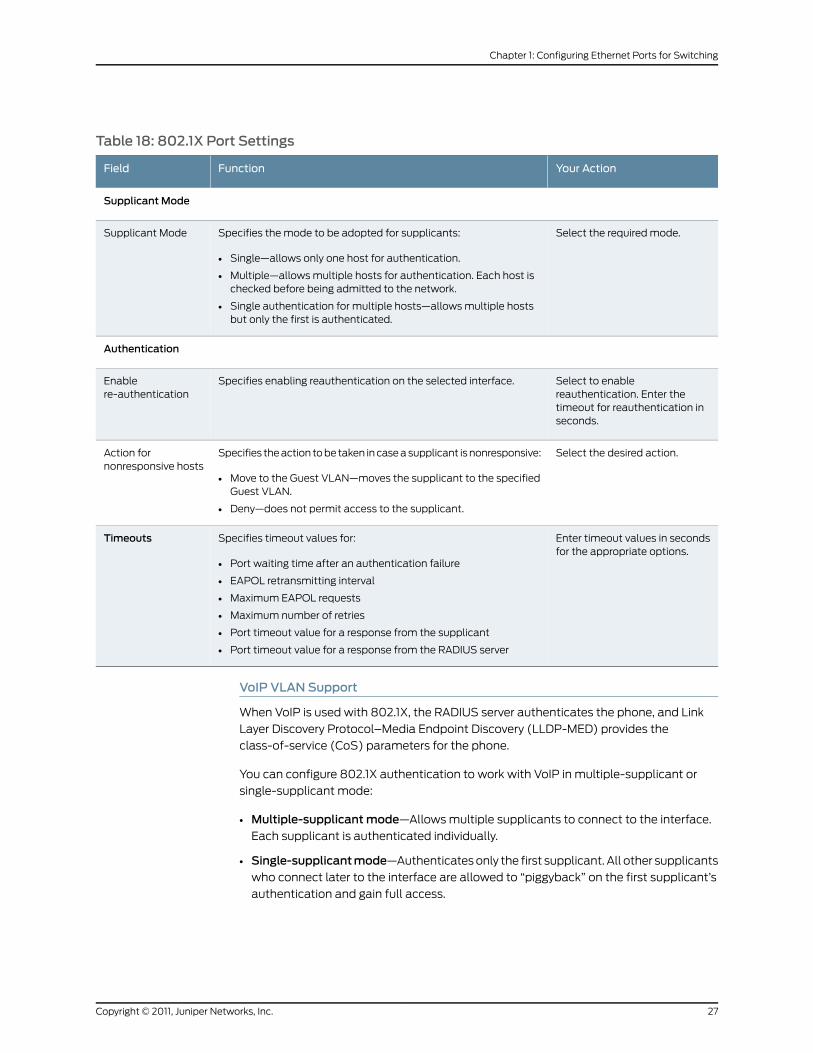
Table 18: 802.1X Port Settings
Your ActionFunctionField
Supplicant Mode
Select the required mode.Specifies the mode to be adopted for supplicants:
• Single—allows only one host for authentication.
• Multiple—allows multiple hosts for authentication. Each host ischecked before being admitted to the network.
• Single authentication for multiple hosts—allows multiple hostsbut only the first is authenticated.
Supplicant Mode
Authentication
Select to enablereauthentication. Enter thetimeout for reauthentication inseconds.
Specifies enabling reauthentication on the selected interface.Enablere-authentication
Select the desired action.Specifies the action to be taken in case a supplicant is nonresponsive:
• Move to the Guest VLAN—moves the supplicant to the specifiedGuest VLAN.
• Deny—does not permit access to the supplicant.
Action fornonresponsive hosts
Enter timeout values in secondsfor the appropriate options.
Specifies timeout values for:
• Port waiting time after an authentication failure
• EAPOL retransmitting interval
• Maximum EAPOL requests
• Maximum number of retries
• Port timeout value for a response from the supplicant
• Port timeout value for a response from the RADIUS server
Timeouts
VoIP VLAN Support
When VoIP is used with 802.1X, the RADIUS server authenticates the phone, and Link
Layer Discovery Protocol–Media Endpoint Discovery (LLDP-MED) provides the
class-of-service (CoS) parameters for the phone.
You can configure 802.1X authentication to work with VoIP in multiple-supplicant or
single-supplicant mode:
• Multiple-supplicantmode—Allows multiple supplicants to connect to the interface.
Each supplicant is authenticated individually.
• Single-supplicantmode—Authenticates only the first supplicant. All other supplicants
who connect later to the interface are allowed to “piggyback” on the first supplicant’s
authentication and gain full access.
27Copyright © 2011, Juniper Networks, Inc.
Chapter 1: Configuring Ethernet Ports for Switching
RADIUS Accounting
Configuring RADIUS accounting on a SRX Series or J Series device lets you collect
statistical data about users logging on and off a LAN, and sends it to a RADIUS accounting
server. The collected data can be used for general network monitoring, to analyze and
track usage patterns, or to bill a user based on the amount of time or type of services
accessed.
To configure RADIUS accounting, specify one or more RADIUS accounting servers to
receive the statistical data from the device, and select the type of accounting data to be
collected. To view the collected statistics, you can access the log file configured to receive
them.
Server Reject VLAN
By default, when authentication fails, the supplicant is denied access to the network.
However, you can specify a VLAN to which the supplicant is moved if authentication fails.
The server reject VLAN is similar to a guest VLAN. With a server reject VLAN, however,
authentication is first attempted by credential, then by MAC address. If both authentication
methods fail, the supplicant is given access to a predetermined VLAN with limited network
access.
RelatedDocumentation
Junos OS Feature Support Reference for SRX Series and J Series Devices•
• Example: Configuring 802.1x Authentication on page 28
• Ethernet Ports Switching Overview on page 3
• Verifying Switching Mode Configuration on page 9
Example: Configuring 802.1x Authentication
This example shows how to configure 802.1X authentication, configure RADIUS, and
configure a guest VLAN.
• Requirements on page 28
• Overview on page 28
• Configuration on page 29
Requirements
Before you begin:
• Verify that the interfaces to use are in switch mode. See “Example: Configuring Switching
Modes” on page 8.
• Review switching mode and VLAN information. See “Understanding Switching Modes”
on page 8 and “Understanding VLANs” on page 10.
Overview
In this example, you configure 802.1X authentication.
Copyright © 2011, Juniper Networks, Inc.28
Junos OS Layer 2 Bridging and Switching Configuration Guide for Security Devices

Configuration
GUI Step-by-StepProcedure
From the Configure menu, select Security > 802.1X.
The 802.1X screen displays a list of interfaces, whether 802.1X security has been
enabled, and the assigned port role.
1.
When you select a particular interface, the Details section displays 802.1X details for
the selected interface.
NOTE: After youmake changes to the configuration, clickOK to checkyour configuration and save it as a candidate configuration, then clickCommit Options>Commit.
2. Click one: RADIUS Servers or Exclusion List. Click Add or Edit to add or modify the
settings.
• Edit—specifies 802.1X settings for the selected interface.
• Apply 802.1X Profile—applies a predefined 802.1X profile based on the port role.
If a message appears asking if you want to configure a RADIUS server, click Yes
and enter information.
• 802.1X Configuration—configures custom 802.1X settings for the selected
interface. If a message appears asking if you want to configure a RADIUS server,
click Yes and enter information.
• Delete—deletes the existing 802.1X authentication configuration on the selected
interface.
RelatedDocumentation
Junos OS Feature Support Reference for SRX Series and J Series Devices•
• Understanding 802.1X Port-Based Network Authentication on page 23
• Ethernet Ports Switching Overview on page 3
• Verifying Switching Mode Configuration on page 9
Example: Specifying RADIUS Server Connections on the Device
This example shows how to specify a RADIUS server for 802.1X authentication to provide
network edge security.
• Requirements on page 30
• Overview on page 30
• Configuration on page 30
• Verification on page 32
29Copyright © 2011, Juniper Networks, Inc.
Chapter 1: Configuring Ethernet Ports for Switching
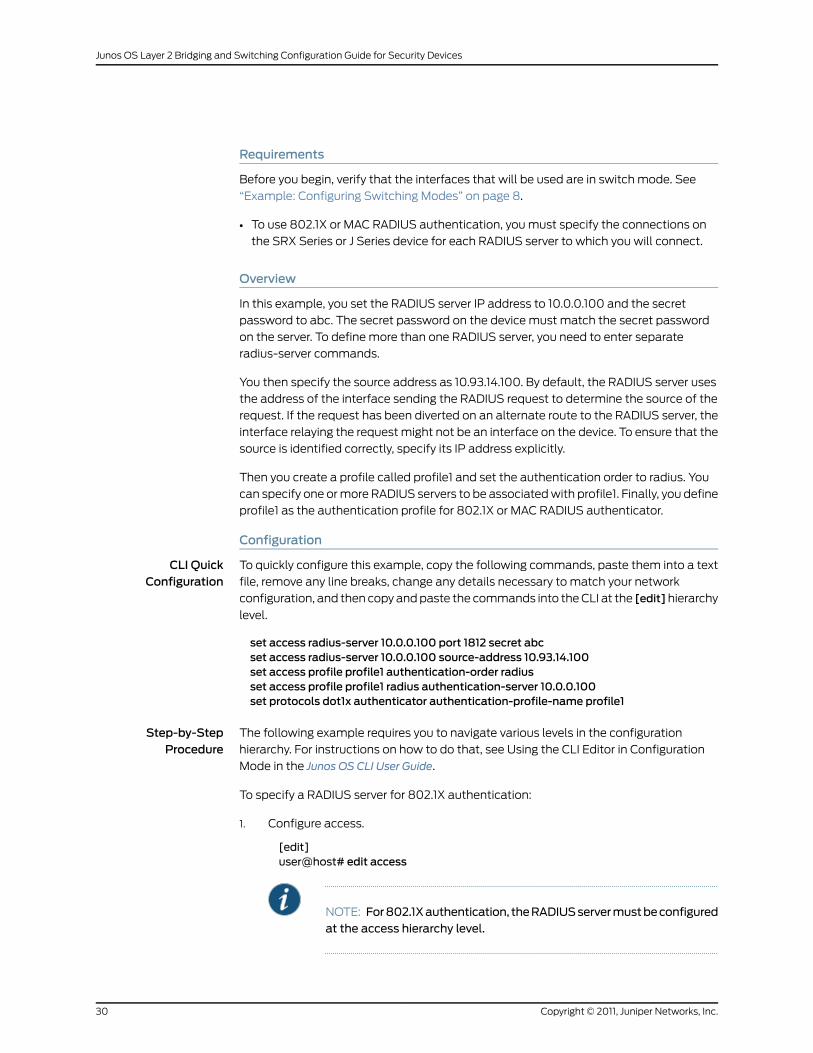
Requirements
Before you begin, verify that the interfaces that will be used are in switch mode. See
“Example: Configuring Switching Modes” on page 8.
• To use 802.1X or MAC RADIUS authentication, you must specify the connections on
the SRX Series or J Series device for each RADIUS server to which you will connect.
Overview
In this example, you set the RADIUS server IP address to 10.0.0.100 and the secret
password to abc. The secret password on the device must match the secret password
on the server. To define more than one RADIUS server, you need to enter separate
radius-server commands.
You then specify the source address as 10.93.14.100. By default, the RADIUS server uses
the address of the interface sending the RADIUS request to determine the source of the
request. If the request has been diverted on an alternate route to the RADIUS server, the
interface relaying the request might not be an interface on the device. To ensure that the
source is identified correctly, specify its IP address explicitly.
Then you create a profile called profile1 and set the authentication order to radius. You
can specify one or more RADIUS servers to be associated with profile1. Finally, you define
profile1 as the authentication profile for 802.1X or MAC RADIUS authenticator.
Configuration
CLI QuickConfiguration
To quickly configure this example, copy the following commands, paste them into a text
file, remove any line breaks, change any details necessary to match your network
configuration, and then copy and paste the commands into the CLI at the [edit]hierarchy
level.
set access radius-server 10.0.0.100 port 1812 secret abcset access radius-server 10.0.0.100 source-address 10.93.14.100set access profile profile1 authentication-order radiusset access profile profile1 radius authentication-server 10.0.0.100set protocols dot1x authenticator authentication-profile-name profile1
Step-by-StepProcedure
The following example requires you to navigate various levels in the configuration
hierarchy. For instructions on how to do that, see Using the CLI Editor in Configuration
Mode in the Junos OS CLI User Guide.
To specify a RADIUS server for 802.1X authentication:
1. Configure access.
[edit]user@host# edit access
NOTE: For802.1Xauthentication, theRADIUSservermustbeconfiguredat the access hierarchy level.
Copyright © 2011, Juniper Networks, Inc.30
Junos OS Layer 2 Bridging and Switching Configuration Guide for Security Devices

2. Define the IP address and the secret password for the RADIUS server.
[edit access]user@host# set radius-server 10.0.0.100 port 1812 secret abc
3. Specify the IP address and the source address.
[edit access]user@host# set radius-server 10.0.0.100 source-address 10.93.14.100
4. Create the profile.
[edit access]user@host# edit profile profile1
5. Configure the authentication order.
[edit access profile profile1]user@host# set authentication-order radius
6. Specify one or more RADIUS servers to be associated with profile1.
[edit access profile profile1]user@host# set radius authentication-server 10.0.0.100
7. Define authentication profile.
[edit]user@host# set protocols dot1x authenticator authentication-profile-nameprofile1
Results From configuration mode, confirm your configuration by entering the show access and
showprotocolsdot1xcommands. If the output does not display the intended configuration,
repeat the configuration instructions in this example to correct it.
[edit]user@host# show accessradius-server {10.0.0.100 {port 1812;secret "$9$mf5F6/tOBE"; ## SECRET-DATAsource-address 10.93.14.100;
}}profile profile1 {authentication-order radius;radius {authentication-server 10.0.0.100;
}}[edit]user@host# show protocols dot1xauthenticator {authentication-profile-name profile1;
}
If you are done configuring the device, enter commit from configuration mode.
31Copyright © 2011, Juniper Networks, Inc.
Chapter 1: Configuring Ethernet Ports for Switching
Verification
To confirm that the configuration is working properly, perform this task:
• Verifying a RADIUS Server on page 32
Verifying a RADIUS Server
Purpose Verify that the RADIUS server is configured properly.
Action From configuration mode, enter the show access and show protocols dot1x commands.
RelatedDocumentation
Junos OS Feature Support Reference for SRX Series and J Series Devices•
• Understanding 802.1X Port-Based Network Authentication on page 23
• Understanding Switching Modes on page 8
• Understanding VLANs on page 10
• Ethernet Ports Switching Overview on page 3
• Example: Configuring 802.1x Authentication on page 28
Example: Configuring 802.1x Interface Settings
This example shows how to configure 802.1X interface settings for network edge security.
• Requirements on page 32
• Overview on page 32
• Configuration on page 33
• Verification on page 34
Requirements
Before you begin:
• Verify that the interfaces that will be used are in switch mode. See “Example: Configuring
Switching Modes” on page 8.
• Ensure that the interfaces are defined in the interfaces hierarchy with family
ethernet-switching.
Overview
In this example, you set the supplicant mode to multiple after configuring protocol dot1x
and authenticator interface ge-0/0/5. You then enable reauthentication and set the
reauthentication interval to 120. You configure the interface timeout value for the response
from the supplicant as 5. You then configure the timeout for the interface before it resends
an authentication request to the RADIUS server as 5. You specify the time, in seconds,
the interface waits before retransmitting the initial EAPoL PDUs to the supplicant as 60.
Finally, you configure the maximum number of times an EAPoL request packet is
retransmitted to the supplicant before the authentication session times out as 5.
Copyright © 2011, Juniper Networks, Inc.32
Junos OS Layer 2 Bridging and Switching Configuration Guide for Security Devices

Configuration
CLI QuickConfiguration
To quickly configure this example, copy the following commands, paste them into a text
file, remove any line breaks, change any details necessary to match your network
configuration, and then copy and paste the commands into the CLI at the [edit]hierarchy
level.
setprotocolsdot1xauthenticator interfacege-0/0/5supplicantmultiple reauthentication120
setprotocolsdot1xauthenticator interfacege-0/0/5supplicant-timeout5server-timeout5 transmit-period 60
set protocols dot1x authenticator interface ge-0/0/5maximum-requests 5
Step-by-StepProcedure
The following example requires you to navigate various levels in the configuration
hierarchy. For instructions on how to do that, see Using the CLI Editor in Configuration
Mode in the Junos OS CLI User Guide.
To configure 802.1x interface settings:
1. Configure the protocol.
[edit]user@host# edit protocols dot1x
2. Configure an interface.
[edit protocols dot1x]user@host# edit authenticator interface ge-0/0/5
3. Configure the supplicant mode.
[edit protocols dot1x authenticator interface ge-0/0/5.0]user@host# set supplicantmultiple
4. Enable reauthentication and specify the reauthentication interval.
[edit protocols dot1x authenticator interface ge-0/0/5.0]user@host# set reauthentication 120
5. Configure the interface timeout value for the response from the supplicant.
[edit protocols dot1x authenticator interface ge-0/0/5.0]user@host# set supplicant-timeout 5
6. Set the server timeout value.
[edit protocols dot1x authenticator interface ge-0/0/5.0]user@host# set server-timeout 5
7. Configure transmit period.
[edit protocols dot1x authenticator interface ge-0/0/5.0]user@host# set transmit-period 60
8. Specify the maximum request value.
[edit protocols dot1x authenticator interface ge-0/0/5.0]user@host# setmaximum-requests 5
33Copyright © 2011, Juniper Networks, Inc.
Chapter 1: Configuring Ethernet Ports for Switching
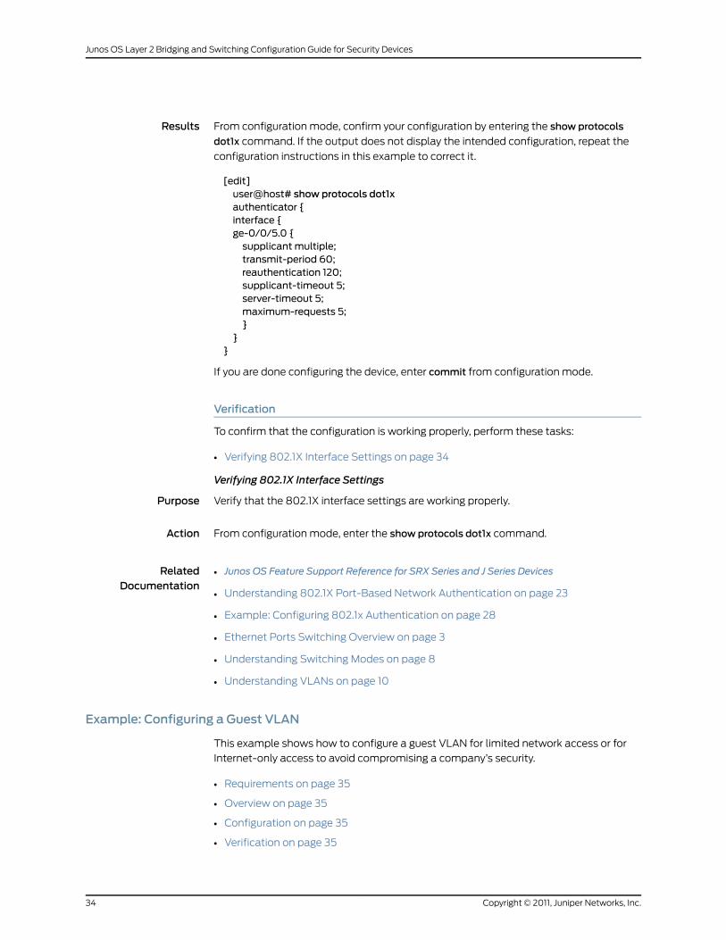
Results From configuration mode, confirm your configuration by entering the show protocols
dot1x command. If the output does not display the intended configuration, repeat the
configuration instructions in this example to correct it.
[edit]user@host# show protocols dot1xauthenticator {interface {ge-0/0/5.0 {supplicant multiple;transmit-period 60;reauthentication 120;supplicant-timeout 5;server-timeout 5;maximum-requests 5;}
}}
If you are done configuring the device, enter commit from configuration mode.
Verification
To confirm that the configuration is working properly, perform these tasks:
• Verifying 802.1X Interface Settings on page 34
Verifying 802.1X Interface Settings
Purpose Verify that the 802.1X interface settings are working properly.
Action From configuration mode, enter the show protocols dot1x command.
RelatedDocumentation
Junos OS Feature Support Reference for SRX Series and J Series Devices•
• Understanding 802.1X Port-Based Network Authentication on page 23
• Example: Configuring 802.1x Authentication on page 28
• Ethernet Ports Switching Overview on page 3
• Understanding Switching Modes on page 8
• Understanding VLANs on page 10
Example: Configuring a Guest VLAN
This example shows how to configure a guest VLAN for limited network access or for
Internet-only access to avoid compromising a company’s security.
• Requirements on page 35
• Overview on page 35
• Configuration on page 35
• Verification on page 35
Copyright © 2011, Juniper Networks, Inc.34
Junos OS Layer 2 Bridging and Switching Configuration Guide for Security Devices
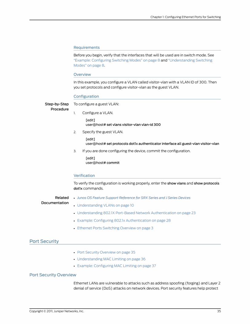
Requirements
Before you begin, verify that the interfaces that will be used are in switch mode. See
“Example: Configuring Switching Modes” on page 8 and “Understanding Switching
Modes” on page 8.
Overview
In this example, you configure a VLAN called visitor-vlan with a VLAN ID of 300. Then
you set protocols and configure visitor-vlan as the guest VLAN.
Configuration
Step-by-StepProcedure
To configure a guest VLAN:
Configure a VLAN.1.
[edit]user@host# set vlans visitor-vlan vlan-id 300
2. Specify the guest VLAN.
[edit]user@host# set protocols dot1x authenticator interface all guest-vlan visitor-vlan
3. If you are done configuring the device, commit the configuration.
[edit]user@host# commit
Verification
To verify the configuration is working properly, enter the show vlans and show protocols
dot1x commands.
RelatedDocumentation
Junos OS Feature Support Reference for SRX Series and J Series Devices•
• Understanding VLANs on page 10
• Understanding 802.1X Port-Based Network Authentication on page 23
• Example: Configuring 802.1x Authentication on page 28
• Ethernet Ports Switching Overview on page 3
Port Security
• Port Security Overview on page 35
• Understanding MAC Limiting on page 36
• Example: Configuring MAC Limiting on page 37
Port Security Overview
Ethernet LANs are vulnerable to attacks such as address spoofing (forging) and Layer 2
denial of service (DoS) attacks on network devices. Port security features help protect
35Copyright © 2011, Juniper Networks, Inc.
Chapter 1: Configuring Ethernet Ports for Switching

the access ports on your services gateway against the losses of information and
productivity that can result from such attacks.
Junos OS on SRX Series devices provides features to help secure ports on a switching
port on the services gateway. The ports can be categorized as either trusted or untrusted.
You apply policies appropriate to those categories to protect against various types of
attacks.
The MAC limit port security feature can be turned on to obtain the most robust port
security level. Basic port security features are enabled in the services gateway's default
configuration. You can configure additional features with minimal configuration steps.
RelatedDocumentation
Ethernet Ports Switching Overview on page 3•
• Understanding MAC Limiting on page 36
• Verifying Switching Mode Configuration on page 9
UnderstandingMAC Limiting
MAC limiting protects against flooding of the Ethernet switching table (also known as
the MAC forwarding table or Layer 2 forwarding table). You enable this feature on
interfaces (ports). MAC move limiting detects MAC movement and MAC spoofing on
access interfaces. You enable this feature on VLANs.
MAC limiting sets a limit on the number of MAC addresses that can be learned dynamically
on a single Layer 2 access interface or on all the Layer 2 access interfaces on the services
gateway.
You configure the maximum number of dynamic MAC addresses allowed per interface.
When the limit is exceeded, incoming packets with new MAC addresses are treated as
specified by the configuration.
You can choose to have one of the following actions performed when the MAC addresses
limit is exceeded:
• drop—Drop the packet and generate an alarm, an SNMP trap, or a system log entry.
This is the default.
• log—Do not drop the packet but generate an alarm, an SNMP trap, or a system log
entry.
• none—Take no action.
• shutdown—Disable the interface and generate an alarm. If you have configured the
services gateway with theport-error-disable statement, the disabled interface recovers
automatically upon expiration of the specified disable timeout. If you have not
configured the services gateway for autorecovery from port error disabled conditions,
you can bring up the disabled interfaces with running the clear ethernet-switching
port-error command.
Copyright © 2011, Juniper Networks, Inc.36
Junos OS Layer 2 Bridging and Switching Configuration Guide for Security Devices

NOTE: MAC limit is only applied to newMAC learning requests. If you alreadyhave 10 learnedMACaddresses and you configure the limit as 5, all theMACswill remain in the forwarding database (FDB) table. Once the learnedMACaddressesageout(orareclearedby theuserwith theclearethernet-switchingcommand), they are not relearned.
MAC limiting does not apply to static MAC addresses. Users can configureany number of static MAC addresses independent of MAC limiting and all ofthem are added to FDB.
RelatedDocumentation
Example: Configuring MAC Limiting on page 37•
• Port Security Overview on page 35
• Ethernet Ports Switching Overview on page 3
• Verifying Switching Mode Configuration on page 9
Example: ConfiguringMAC Limiting
• Requirements on page 37
• Overview on page 37
• Configuration on page 37
• Verification on page 38
Requirements
Before you begin, verify that the interfaces that will be used are in switch mode. See
“Example: Configuring Switching Modes” on page 8 and “Understanding Switching
Modes” on page 8.
Overview
MAC limiting protects against flooding of the Ethernet switching table on the SRX Series
Services Gateways. MAC limiting sets a limit on the number of MAC addresses that can
be learned on a single Layer 2 access interface (port).
This example shows how to configure port security features by setting a MAC limit of 5.
Configuration
Step-by-StepProcedure
The action is not specified, so the switch performs the default action drop if the limit is
exceeded:
1. On a single interface (here, the interface is ge-0/0/1):
[edit ethernet-switching-options secure-access-port]user@host# set interface ge–0/0/1 mac-limit 5
2. On all interfaces:
[edit ethernet-switching-options secure-access-port]
37Copyright © 2011, Juniper Networks, Inc.
Chapter 1: Configuring Ethernet Ports for Switching

user@host# set interface all mac–limit 5
NOTE: Do not set themac-limit to 1. The first learnedMAC address isoften inserted into theFDBautomatically (forexample, for routedVLANinterfaces the first MAC address inserted into the forwarding databaseis the MAC address of the RVI; for Aggregated Ethernet bundles usingLACP, the first MAC address inserted into the FDB in the forwardingtable is thesourceaddressof theprotocolpacket).Theservicesgatewaywill therefore not learn MAC addresses other than the automaticaddresses when themac-limit is set to 1, and this will cause problemswith MAC learning and forwarding.
3. For specifying specific allowed MAC addresses:
• On a single interface (here, the interface is ge-0/0/2):
[edit ethernet-switching-options secure-access-port]user@host# set interface ge–0/0/2 allowed-mac 00:05:85:3A:82:80user@host# set interface ge–0/0/2 allowed-mac 00:05:85:3A:82:81user@host# set interface ge–0/0/2 allowed-mac 00:05:85:3A:82:83
• On all interfaces:
[edit ethernet-switching-options secure-access-port]user@host# set interface all allowed-mac 00:05:85:3A:82:80user@host# set interface all allowed-mac 00:05:85:3A:82:81user@host# set interface all allowed-mac 00:05:85:3A:82:83
Verification
Verifying That MAC Limiting IsWorking Correctly on the Services Gateway
Purpose Verify that MAC limiting is working on the services gateway.
Action Display the learned MAC addresses. The following sample output shows the results when
two packets were sent from hosts on ge-0/0/1 and five packets requests were sent from
hosts on ge-0/0/2, with both interfaces set to a MAC limit of 4 with the action drop:
user@host> show ethernet-switching tableEthernet-switching table: 7 entries, 6 learnedVLAN MAC address Type Age Interfacesemployee-vlan * Flood - ge-0/0/2.0employee-vlan 00:05:85:3A:82:77 Learn 0 ge-0/0/1.0employee-vlan 00:05:85:3A:82:79 Learn 0 ge-0/0/1.0employee-vlan 00:05:85:3A:82:80 Learn 0 ge-0/0/2.0employee-vlan 00:05:85:3A:82:81 Learn 0 ge-0/0/2.0employee-vlan 00:05:85:3A:82:83 Learn 0 ge-0/0/2.0employee-vlan 00:05:85:3A:82:85 Learn 0 ge-0/0/2.0
Meaning The sample output shows that with a MAC limit of 4 for each interface, the packet for a
fifth MAC address on ge-0/0/2 was dropped because it exceeded the MAC limit. The
address was not learned, and thus an asterisk (*) rather than an address appears in the
MAC address column in the first line of the sample output.
Copyright © 2011, Juniper Networks, Inc.38
Junos OS Layer 2 Bridging and Switching Configuration Guide for Security Devices
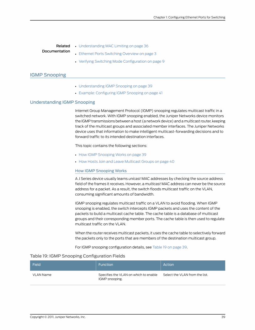
RelatedDocumentation
Understanding MAC Limiting on page 36•
• Ethernet Ports Switching Overview on page 3
• Verifying Switching Mode Configuration on page 9
IGMP Snooping
• Understanding IGMP Snooping on page 39
• Example: Configuring IGMP Snooping on page 41
Understanding IGMP Snooping
Internet Group Management Protocol (IGMP) snooping regulates multicast traffic in a
switched network. With IGMP snooping enabled, the Juniper Networks device monitors
the IGMP transmissions between a host (a network device) and a multicast router, keeping
track of the multicast groups and associated member interfaces. The Juniper Networks
device uses that information to make intelligent multicast-forwarding decisions and to
forward traffic to its intended destination interfaces.
This topic contains the following sections:
• How IGMP Snooping Works on page 39
• How Hosts Join and Leave Multicast Groups on page 40
How IGMP SnoopingWorks
A J Series device usually learns unicast MAC addresses by checking the source address
field of the frames it receives. However, a multicast MAC address can never be the source
address for a packet. As a result, the switch floods multicast traffic on the VLAN,
consuming significant amounts of bandwidth.
IGMP snooping regulates multicast traffic on a VLAN to avoid flooding. When IGMP
snooping is enabled, the switch intercepts IGMP packets and uses the content of the
packets to build a multicast cache table. The cache table is a database of multicast
groups and their corresponding member ports. The cache table is then used to regulate
multicast traffic on the VLAN.
When the router receives multicast packets, it uses the cache table to selectively forward
the packets only to the ports that are members of the destination multicast group.
For IGMP snooping configuration details, see Table 19 on page 39.
Table 19: IGMP Snooping Configuration Fields
ActionFunctionField
Select the VLAN from the list.Specifies the VLAN on which to enableIGMP snooping.
VLAN Name
39Copyright © 2011, Juniper Networks, Inc.
Chapter 1: Configuring Ethernet Ports for Switching
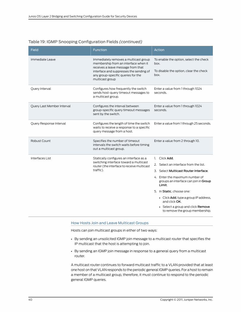
Table 19: IGMP Snooping Configuration Fields (continued)
ActionFunctionField
To enable the option, select the checkbox.
To disable the option, clear the checkbox.
Immediately removes a multicast groupmembership from an interface when itreceives a leave message from thatinterface and suppresses the sending ofany group-specific queries for themulticast group
Immediate Leave
Enter a value from 1 through 1024seconds.
Configures how frequently the switchsends host-query timeout messages toa multicast group.
Query Interval
Enter a value from 1 through 1024seconds.
Configures the interval betweengroup-specific query timeout messagessent by the switch.
Query Last Member Interval
Enter a value from 1 through 25 seconds.Configures the length of time the switchwaits to receive a response to a specificquery message from a host.
Query Response Interval
Enter a value from 2 through 10.Specifies the number of timeoutintervals the switch waits before timingout a multicast group.
Robust Count
1. Click Add.
2. Select an interface from the list.
3. Select Multicast Router Interface.
4. Enter the maximum number ofgroups an interface can join inGroupLimit.
5. In Static, choose one:
• ClickAdd, type a group IP address,and click OK.
• Select a group and click Removeto remove the group membership.
Statically configures an interface as aswitching interface toward a multicastrouter (the interface to receive multicasttraffic).
Interfaces List
HowHosts Join and LeaveMulticast Groups
Hosts can join multicast groups in either of two ways:
• By sending an unsolicited IGMP join message to a multicast router that specifies the
IP multicast that the host is attempting to join.
• By sending an IGMP join message in response to a general query from a multicast
router.
A multicast router continues to forward multicast traffic to a VLAN provided that at least
one host on that VLAN responds to the periodic general IGMP queries. For a host to remain
a member of a multicast group, therefore, it must continue to respond to the periodic
general IGMP queries.
Copyright © 2011, Juniper Networks, Inc.40
Junos OS Layer 2 Bridging and Switching Configuration Guide for Security Devices
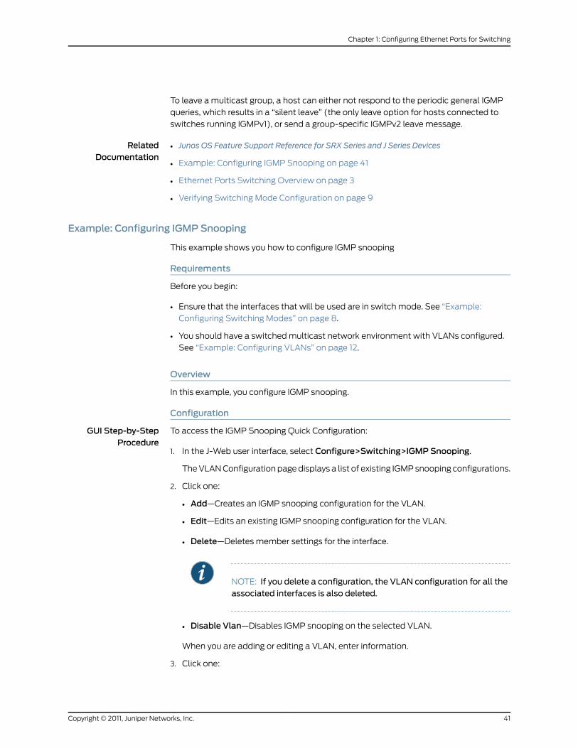
To leave a multicast group, a host can either not respond to the periodic general IGMP
queries, which results in a “silent leave” (the only leave option for hosts connected to
switches running IGMPv1), or send a group-specific IGMPv2 leave message.
RelatedDocumentation
Junos OS Feature Support Reference for SRX Series and J Series Devices•
• Example: Configuring IGMP Snooping on page 41
• Ethernet Ports Switching Overview on page 3
• Verifying Switching Mode Configuration on page 9
Example: Configuring IGMP Snooping
This example shows you how to configure IGMP snooping
Requirements
Before you begin:
• Ensure that the interfaces that will be used are in switch mode. See “Example:
Configuring Switching Modes” on page 8.
• You should have a switched multicast network environment with VLANs configured.
See “Example: Configuring VLANs” on page 12.
Overview
In this example, you configure IGMP snooping.
Configuration
GUI Step-by-StepProcedure
To access the IGMP Snooping Quick Configuration:
In the J-Web user interface, select Configure>Switching>IGMP Snooping.1.
The VLAN Configuration page displays a list of existing IGMP snooping configurations.
2. Click one:
• Add—Creates an IGMP snooping configuration for the VLAN.
• Edit—Edits an existing IGMP snooping configuration for the VLAN.
• Delete—Deletes member settings for the interface.
NOTE: If you delete a configuration, the VLAN configuration for all theassociated interfaces is also deleted.
• Disable Vlan—Disables IGMP snooping on the selected VLAN.
When you are adding or editing a VLAN, enter information.
3. Click one:
41Copyright © 2011, Juniper Networks, Inc.
Chapter 1: Configuring Ethernet Ports for Switching
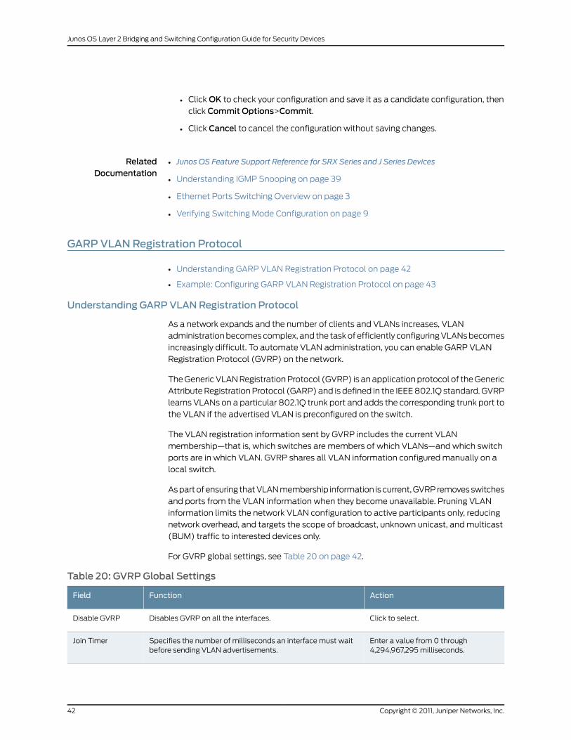
• Click OK to check your configuration and save it as a candidate configuration, then
click Commit Options>Commit.
• Click Cancel to cancel the configuration without saving changes.
RelatedDocumentation
Junos OS Feature Support Reference for SRX Series and J Series Devices•
• Understanding IGMP Snooping on page 39
• Ethernet Ports Switching Overview on page 3
• Verifying Switching Mode Configuration on page 9
GARP VLANRegistration Protocol
• Understanding GARP VLAN Registration Protocol on page 42
• Example: Configuring GARP VLAN Registration Protocol on page 43
Understanding GARP VLANRegistration Protocol
As a network expands and the number of clients and VLANs increases, VLAN
administration becomes complex, and the task of efficiently configuring VLANs becomes
increasingly difficult. To automate VLAN administration, you can enable GARP VLAN
Registration Protocol (GVRP) on the network.
The Generic VLAN Registration Protocol (GVRP) is an application protocol of the Generic
Attribute Registration Protocol (GARP) and is defined in the IEEE 802.1Q standard. GVRP
learns VLANs on a particular 802.1Q trunk port and adds the corresponding trunk port to
the VLAN if the advertised VLAN is preconfigured on the switch.
The VLAN registration information sent by GVRP includes the current VLAN
membership—that is, which switches are members of which VLANs—and which switch
ports are in which VLAN. GVRP shares all VLAN information configured manually on a
local switch.
As part of ensuring that VLAN membership information is current, GVRP removes switches
and ports from the VLAN information when they become unavailable. Pruning VLAN
information limits the network VLAN configuration to active participants only, reducing
network overhead, and targets the scope of broadcast, unknown unicast, and multicast
(BUM) traffic to interested devices only.
For GVRP global settings, see Table 20 on page 42.
Table 20: GVRPGlobal Settings
ActionFunctionField
Click to select.Disables GVRP on all the interfaces.Disable GVRP
Enter a value from 0 through4,294,967,295 milliseconds.
Specifies the number of milliseconds an interface must waitbefore sending VLAN advertisements.
Join Timer
Copyright © 2011, Juniper Networks, Inc.42
Junos OS Layer 2 Bridging and Switching Configuration Guide for Security Devices
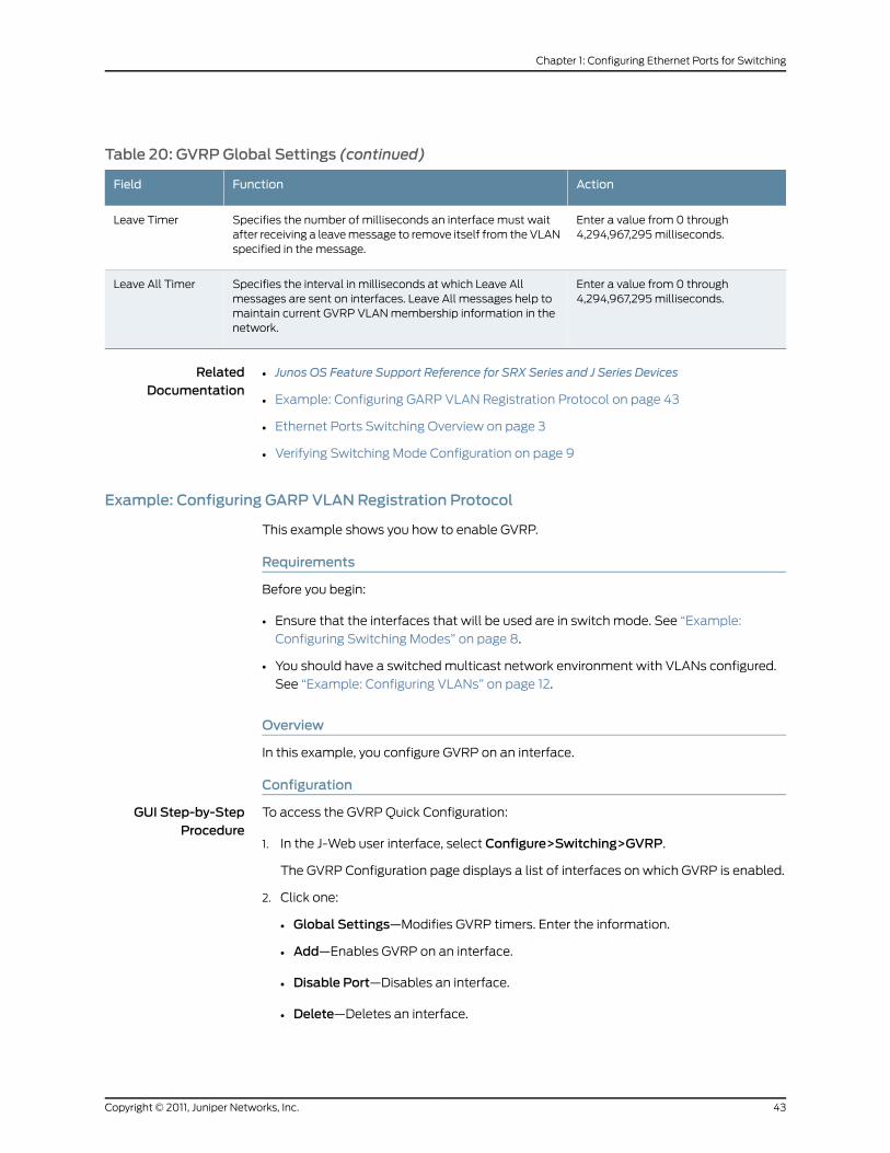
Table 20: GVRPGlobal Settings (continued)
ActionFunctionField
Enter a value from 0 through4,294,967,295 milliseconds.
Specifies the number of milliseconds an interface must waitafter receiving a leave message to remove itself from the VLANspecified in the message.
Leave Timer
Enter a value from 0 through4,294,967,295 milliseconds.
Specifies the interval in milliseconds at which Leave Allmessages are sent on interfaces. Leave All messages help tomaintain current GVRP VLAN membership information in thenetwork.
Leave All Timer
RelatedDocumentation
Junos OS Feature Support Reference for SRX Series and J Series Devices•
• Example: Configuring GARP VLAN Registration Protocol on page 43
• Ethernet Ports Switching Overview on page 3
• Verifying Switching Mode Configuration on page 9
Example: Configuring GARP VLANRegistration Protocol
This example shows you how to enable GVRP.
Requirements
Before you begin:
• Ensure that the interfaces that will be used are in switch mode. See “Example:
Configuring Switching Modes” on page 8.
• You should have a switched multicast network environment with VLANs configured.
See “Example: Configuring VLANs” on page 12.
Overview
In this example, you configure GVRP on an interface.
Configuration
GUI Step-by-StepProcedure
To access the GVRP Quick Configuration:
In the J-Web user interface, select Configure>Switching>GVRP.1.
The GVRP Configuration page displays a list of interfaces on which GVRP is enabled.
2. Click one:
• Global Settings—Modifies GVRP timers. Enter the information.
• Add—Enables GVRP on an interface.
• Disable Port—Disables an interface.
• Delete—Deletes an interface.
43Copyright © 2011, Juniper Networks, Inc.
Chapter 1: Configuring Ethernet Ports for Switching
3. Click one:
• Click OK to check your configuration and save it as a candidate configuration, then
click Commit Options>Commit.
• Click Cancel to cancel the configuration without saving changes.
RelatedDocumentation
• Junos OS Feature Support Reference for SRX Series and J Series Devices
• Understanding GARP VLAN Registration Protocol on page 42
• Ethernet Ports Switching Overview on page 3
• Verifying Switching Mode Configuration on page 9
Copyright © 2011, Juniper Networks, Inc.44
Junos OS Layer 2 Bridging and Switching Configuration Guide for Security Devices
CHAPTER 2
Configuring Layer 2 Bridging andTransparent Mode
• Layer 2 Bridging and Transparent Mode Overview on page 45
• Bridge Domains on page 47
• Layer 2 Interfaces on page 49
• Layer 2 Security Zones and Security Policies on page 56
• Understanding Firewall User Authentication in Transparent Mode on page 61
• Understanding Layer 2 Forwarding Tables on page 62
• Example: Configuring the Default Learning for Unknown MAC Addresses on page 63
• Understanding Layer 2 Transparent Mode Chassis Clusters on page 64
• Example: Configuring Redundant Ethernet Interfaces for Layer 2 Transparent Mode
Chassis Clusters on page 66
• Transparent Mode Devices on page 67
• Example: Configuring Layer 2 Trunk Interfaces with Multiple Units on page 74
Layer 2 Bridging and Transparent Mode Overview
For SRX Series devices, transparent mode provides full security services for Layer 2
bridging capabilities. On these SRX Series devices, you can configure one or more bridge
domains to perform Layer 2 bridging. A bridge domain is a set of logical interfaces that
share the same flooding or broadcast characteristics. Like a virtual LAN (VLAN), a bridge
domain spans one or more ports of multiple devices. Thus, the SRX Series device can
function as a Layer 2 switch with multiple bridge domains that participate in the same
Layer 2 network.
In transparent mode, the SRX Series device filters packets that traverse the device without
modifying any of the source or destination information in the IP packet headers.
Transparent mode is useful for protecting servers that mainly receive traffic from untrusted
sources because there is no need to reconfigure the IP settings of routers or protected
servers.
NOTE: Transparent mode is supported only for IPv4 traffic.
45Copyright © 2011, Juniper Networks, Inc.
In transparent mode, all physical ports on the device are assigned to Layer 2 interfaces.
Do not route Layer 3 traffic through the device. Layer 2 zones can be configured to host
Layer 2 interfaces, and security policies can be defined between Layer 2 zones. When
packets travel between Layer 2 zones, security policies can be enforced on these packets.
NOTE: Not all security features are supported in transparent mode:
• NAT is not supported.
• IPsec VPN is not supported.
• For ALGs, only DNS, FTP, RTSP, andTFTPALGs are supported. Other ALGsare not supported.
Layer 2 Bridging Exceptions on SRX Series Devices
The bridging functions on the SRX Series devices are similar to the bridging features on
Juniper Networks MX Series routers. However, the following Layer 2 networking features
on MX Series routers are not supported on SRX Series devices:
• Layer 2 control protocols—These protocols are used on MX Series routers for Rapid
Spanning Tree Protocol (RSTP) or Multiple Spanning Tree Protocol (MSTP) in customer
edge interfaces of a VPLS routing instance.
• Virtual switch routing instance—The virtual switching routing instance is used on MX
Series routers to group one or more bridge domains.
• Virtual private LAN services (VPLS) routing instance—The VPLS routing instance is
used on MX Series routers for point-to-multipoint LAN implementations between a
set of sites in a VPN.
In addition, the SRX Series devices do not support the following Layer 2 features:
• Spanning Tree Protocol (STP), RSTP, or MSTP—It is the user’s responsibility to ensure
that no flooding loops exist in the network topology.
• Internet Group Management Protocol (IGMP) snooping—Host-to-router signaling
protocol for IPv4 used to report their multicast group memberships to neighboring
routers and determine whether group members are present during IP multicasting.
• Double-tagged VLANs or IEEE 802.1Q VLAN identifiers encapsulated within 802.1Q
packets (also called “Q in Q” VLAN tagging)—Only untagged or single-tagged VLAN
identifiers are supported on SRX Series devices.
• Nonqualified VLAN learning, where only the MAC address is used for learning within
the bridge domain—VLAN learning on SRX Series devices is qualified; that is, both the
VLAN identifier and MAC address are used.
RelatedDocumentation
Junos OS Feature Support Reference for SRX Series and J Series Devices•
• Understanding Bridge Domains on page 47
• Understanding Transparent Mode Conditions on page 49
Copyright © 2011, Juniper Networks, Inc.46
Junos OS Layer 2 Bridging and Switching Configuration Guide for Security Devices
• Understanding Layer 2 Interfaces on page 50
• Understanding Layer 2 Security Zones on page 56
• Understanding Security Policies in Transparent Mode on page 58
Bridge Domains
This topic includes the following sections:
• Understanding Bridge Domains on page 47
• Example: Configuring Bridge Domains on page 48
Understanding Bridge Domains
The packets that are forwarded within a bridge domain are determined by the VLAN ID
of the packets and the VLAN ID of the bridge domain. Only the packets with VLAN IDs
that match the VLAN ID configured for a bridge domain are forwarded within the bridge
domain.
When configuring bridge domains, you can specify either a single VLAN ID or a list of
specific VLAN IDs. If you specify a list of VLAN IDs, a bridge domain is created for each
VLAN ID in the list. Certain bridge domain properties, such as the integrated routing and
bridging interface (IRB), are not configurable if bridge domains are created in this manner.
Each Layer 2 logical interface configured on the device is implicitly assigned to a bridge
domain based on the VLAN ID of the packets accepted by the interface. You do not need
to explicitly define the logical interfaces when configuring a bridge domain.
You can configure one or more static MAC addresses for a logical interface in a bridge
domain; this is only applicable if you specified a single VLAN ID when creating the bridge
domain.
NOTE: If a static MAC address you configure for a logical interface appearson a different logical interface, packets sent to that interface are dropped.
You can configure the following properties that apply to all bridge domains on the SRX
Series device:
• Layer 2 address learning—Layer 2 address learning is enabled by default. A bridge
domain learns unicast media access control (MAC) addresses to avoid flooding packets
to all interfaces in the bridge domain. Each bridge domain creates a source MAC entry
in its forwarding tables for each source MAC address learned from packets received
on interfaces that belong to the bridge domain. When you disable MAC learning, source
MAC addresses are not dynamically learned, and any packets sent to these source
addresses are flooded into a bridge domain.
• Maximum number of MAC addresses learned from all logical interfaces on the SRX
Series device—After the MAC address limit is reached, the default is for any incoming
packets with a new source MAC address to be forwarded. You can specify that the
47Copyright © 2011, Juniper Networks, Inc.
Chapter 2: Configuring Layer 2 Bridging and Transparent Mode
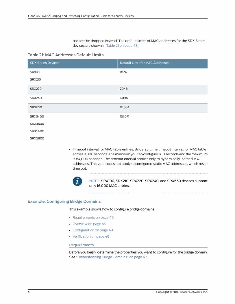
packets be dropped instead. The default limits of MAC addresses for the SRX Series
devices are shown in Table 21 on page 48.
Table 21: MAC Addresses Default Limits
Default Limit for MAC AddressesSRX Series Devices
1024SRX100
SRX210
2048SRX220
4096SRX240
16,384SRX650
131,071SRX3400
SRX3600
SRX5600
SRX5800
• Timeout interval for MAC table entries. By default, the timeout interval for MAC table
entries is 300 seconds. The minimum you can configure is 10 seconds and the maximum
is 64,000 seconds. The timeout interval applies only to dynamically learned MAC
addresses. This value does not apply to configured static MAC addresses, which never
time out.
NOTE: SRX100, SRX210, SRX220, SRX240, and SRX650 devices supportonly 16,000MAC entries.
Example: Configuring Bridge Domains
This example shows how to configure bridge domains.
• Requirements on page 48
• Overview on page 49
• Configuration on page 49
• Verification on page 49
Requirements
Before you begin, determine the properties you want to configure for the bridge domain.
See “Understanding Bridge Domains” on page 47.
Copyright © 2011, Juniper Networks, Inc.48
Junos OS Layer 2 Bridging and Switching Configuration Guide for Security Devices
Overview
In this example, you configure bridge domain bd1 for VLANs 1 and 10, and bridge domain
bd2 for VLAN 2. You then limit the number of MAC addresses learned on all logical
interfaces on the device to 64,000. When this limit is reached, incoming packets with a
new source MAC address will be dropped.
Configuration
Step-by-StepProcedure
To configure bridge domains:
Configure the domain type and VLANs.1.
[edit]user@host# set bridge-domains bd1 vlan-id-list 1-10user@host# set bridge-domains bd2 vlan-id 2
2. Limit the number of MAC addresses.
[edit]user@host# set protocols l2-learning global-mac-limit 64000 packet-action drop
3. If you are done configuring the device, commit the configuration.
[edit]user@host# commit
Verification
To verify the configuration is working properly, enter the show bridge-domains and show
protocols l2-learning commands.
Layer 2 Interfaces
This topic includes the following sections:
• Understanding Transparent Mode Conditions on page 49
• Understanding Layer 2 Interfaces on page 50
• Example: Configuring Layer 2 Logical Interfaces on page 51
• Understanding VLAN Retagging on page 52
• Example: Configuring VLAN Retagging on page 53
• Understanding Integrated Routing and Bridging Interfaces on page 54
• Example: Configuring an IRB Interface on page 54
Understanding Transparent Mode Conditions
A device operates in Layer 2 transparent mode when all physical interfaces on the device
are configured as Layer 2 interfaces. A physical interface is a Layer 2 interface if its logical
interface is configured with the bridge family.
There is no command to define or enable transparent mode on the device. The device
operates in transparent mode when there are interfaces defined as Layer 2 interfaces.
49Copyright © 2011, Juniper Networks, Inc.
Chapter 2: Configuring Layer 2 Bridging and Transparent Mode
The device operates in route mode (the default mode) if there are no physical interfaces
configured as Layer 2 interfaces.
NOTE: TheSRXSeriesdevicecanoperateateither routemodeor transparentmode, but not bothmodes at the same time. Changing themode requires areboot of the device.
You can configure the fxp0out-of-band management interface on the SRX Series device
as a Layer 3 interface, even if Layer 2 interfaces are defined on the device. With the
exception of the fxp0 interface, you must not define Layer 2 and Layer 3 interfaces on
the device’s network ports.
NOTE: There is no fxp0 out-of-bandmanagement interface on the SRX100,SRX210, SRX220, SRX240, and SRX650 devices.
RelatedDocumentation
Junos OS Feature Support Reference for SRX Series and J Series Devices•
• Layer 2 Bridging and Transparent Mode Overview on page 45
• Example: Configuring Layer 2 Logical Interfaces on page 51
• Understanding Layer 2 Interfaces on page 50
Understanding Layer 2 Interfaces
Layer 2 logical interfaces are created by defining one or more logical units on a physical
interface with the family address type bridge. If a physical interface has a bridge family
logical interface, it cannot have any other family type in its logical interfaces. A logical
interface can be configured in one of the following modes:
• Access mode—Interface accepts untagged packets, assigns the specified VLAN identifier
to the packet, and forwards the packet within the bridge domain that is configured
with the matching VLAN identifier.
• Trunk mode—Interface accepts any packet tagged with a VLAN identifier that matches
a specified list of VLAN identifiers. Trunk mode interfaces are generally used to
interconnect switches. To configure a VLAN identifier for untagged packets received
on the physical interface, use the native-vlan-id option. If the native-vlan-id option is
not configured, untagged packets are dropped.
Tagged packets arriving on a trunk mode interface can be rewritten or “retagged” with
a different VLAN identifier. This allows incoming packets to be selectively redirected
to a firewall or other security device.
Copyright © 2011, Juniper Networks, Inc.50
Junos OS Layer 2 Bridging and Switching Configuration Guide for Security Devices
NOTE: Multiple trunkmode logical interfaces can be defined, as long as theVLAN identifiers of a trunk interface do not overlap with those of anothertrunk interface. The native-vlan-idmust belong to a VLAN identifier list
configured for a trunk interface.
RelatedDocumentation
Junos OS Feature Support Reference for SRX Series and J Series Devices•
• Layer 2 Bridging and Transparent Mode Overview on page 45
• Example: Configuring Layer 2 Logical Interfaces on page 51
• Understanding Transparent Mode Conditions on page 49
Example: Configuring Layer 2 Logical Interfaces
This example shows how to configure a Layer 2 logical interface as a trunk port so that
the incoming packets can be selectively redirected to a firewall or other security device.
• Requirements on page 51
• Overview on page 51
• Configuration on page 51
• Verification on page 52
Requirements
Before you begin, configure the bridge domains. See “Example: Configuring Bridge
Domains” on page 48.
Overview
In this example, you configure logical interface ge-3/0/0.0 as a trunk port that carries
traffic for packets tagged with VLAN identifiers 1 through 10; this interface is implicitly
assigned to the previously configured bridge domains bd1 and bd2. Then you assign a
VLAN ID of 10 to any untagged packets received on physical interface ge-3/0/0.
Configuration
Step-by-StepProcedure
The following example requires you to navigate various levels in the configuration
hierarchy. For instructions on how to do that, see Using the CLI Editor in Configuration
Mode in the Junos OS CLI User Guide.
To configure a Layer 2 logical interface as a trunk port:
1. Configure the logical interface.
[edit interfaces ge-3/0/0]user@host# set unit 0 family bridge interface-mode trunk vlan-id-list 1–10
2. Specify a VLAN ID for untagged packets.
[edit interfaces ge-3/0/0]user@host# set vlan-tagging native-vlan-id 10
51Copyright © 2011, Juniper Networks, Inc.
Chapter 2: Configuring Layer 2 Bridging and Transparent Mode

3. If you are done configuring the device, commit the configuration.
[edit]user@host# commit
Verification
To verify the configuration is working properly, enter the show interfaces ge-3/0/0 and
show interfaces ge-3/0/0.0 commands.
RelatedDocumentation
Junos OS Feature Support Reference for SRX Series and J Series Devices•
• Layer 2 Bridging and Transparent Mode Overview on page 45
• Understanding Layer 2 Interfaces on page 50
• Understanding Transparent Mode Conditions on page 49
• Example: Configuring Layer 2 Security Zones on page 57
Understanding VLAN Retagging
The VLAN identifier in packets arriving on a Layer 2 trunk port can be rewritten or
“retagged” with a different internal VLAN identifier. VLAN retagging is a symmetric
operation; upon exiting the same trunk port, the retagged VLAN identifier is replaced with
the original VLAN identifier. VLAN retagging provides a way to selectively screen incoming
packets and redirect them to a firewall or other security device without affecting other
VLAN traffic.
VLAN retagging can be applied only to interfaces configured as Layer 2 trunk interfaces.
These interfaces can include redundant Ethernet interfaces in a Layer 2 transparent mode
chassis cluster configuration.
NOTE: If a trunk port is configured for VLAN retagging, untagged packetsreceived on the port cannot be assigned a VLAN identifier with the VLANretagging configuration. To configure a VLAN identifier for untagged packetsreceived on the physical interface, use the native-vlan-id statement.
To configure VLAN retagging for a Layer 2 trunk interface, specify a one-to-one mapping
of the following:
• Incoming VLAN identifier—VLAN identifier of the incoming packet that is to be retagged.
This VLAN identifier must not be the same VLAN identifier configured with the
native-vlan-id statement for the trunk port.
• Internal VLAN identifier—VLAN identifier for the retagged packet. This VLAN identifier
must be in the VLAN identifier list for the trunk port and must not be the same VLAN
identifier configured with the native-vlan-id statement for the trunk port.
RelatedDocumentation
Junos OS Feature Support Reference for SRX Series and J Series Devices•
• Layer 2 Bridging and Transparent Mode Overview on page 45
Copyright © 2011, Juniper Networks, Inc.52
Junos OS Layer 2 Bridging and Switching Configuration Guide for Security Devices
• Example: Configuring VLAN Retagging on page 53
• Example: Configuring Layer 2 Logical Interfaces on page 51
Example: Configuring VLAN Retagging
This example shows how to configure VLAN retagging on a Layer 2 trunk interface to
selectively screen incoming packets and redirect them to a security device without
affecting other VLAN traffic.
• Requirements on page 53
• Overview on page 53
• Configuration on page 53
• Verification on page 53
Requirements
Before you begin, determine the mapping you want to include for the VLAN retagging.
See “Understanding VLAN Retagging” on page 52.
Overview
In this example, you create a Layer 2 trunk interface called ge-3/0/0 and configure it to
receive packets with VLAN identifiers 1 through 10. Packets that arrive on the interface
with VLAN identifier 11 are retagged with VLAN identifier 2. Before exiting the trunk
interface, VLAN identifier 2 in the retagged packets is replaced with VLAN identifier 11.
All VLAN identifiers in the retagged packets change back when you exit the trunk interface.
Configuration
Step-by-StepProcedure
To configure VLAN retagging on a Layer 2 trunk interface:
Create a Layer 2 trunk interface.1.
[edit]user@host# set interfaces ge-3/0/0 unit 0 family bridge interface-mode trunkvlan-id-list 1–10
2. Configure VLAN retagging.
[edit]user@host# set interfaces ge-3/0/0 unit 0 family bridge vlan-rewrite translate 11 2
3. If you are done configuring the device, commit the configuration.
[edit]user@host# commit
Verification
To verify the configuration is working properly, enter the show interfaces ge-3/0/0
command.
53Copyright © 2011, Juniper Networks, Inc.
Chapter 2: Configuring Layer 2 Bridging and Transparent Mode

RelatedDocumentation
Junos OS Feature Support Reference for SRX Series and J Series Devices•
• Layer 2 Bridging and Transparent Mode Overview on page 45
• Example: Configuring Layer 2 Logical Interfaces on page 51
Understanding Integrated Routing and Bridging Interfaces
For bridge domains configured with a single VLAN identifier, you can optionally configure
an integrated routing and bridging (IRB) interface for management traffic in the bridge
domain. An IRB interface acts as a Layer 3 routing interface for a bridge domain.
NOTE: If you specify aVLAN identifier list in thebridgedomain configuration,you cannot configure an IRB interface for the bridge domain.
In this release, the IRB interface on the SRX Series device does not support traffic
forwarding or routing. In transparent mode, packets arriving on a Layer 2 interface that
are destined for the device’s MAC address are classified as Layer 3 traffic while packets
that are not destined for the device’s MAC address are classified as Layer 2 traffic. Packets
destined for the device’s MAC address are sent to the IRB interface. Packets from the
device’s routing engine are sent out the IRB interface.
You create an IRB logical interface in a similar manner as a Layer 3 interface, but the IRB
interface does not support traffic forwarding or routing. The IRB interface cannot be
assigned to a security zone; however, you can configure certain services on a per-zone
basis to allow host-inbound traffic for management of the device. This allows you to
control the type of traffic that can reach the device from interfaces bound to a specific
zone.
NOTE: You can configure only one IRB logical interface for each bridgedomain.
RelatedDocumentation
Junos OS Feature Support Reference for SRX Series and J Series Devices•
• Layer 2 Bridging and Transparent Mode Overview on page 45
• Example: Configuring an IRB Interface on page 54
• Understanding Bridge Domains on page 47
• Example: Configuring Bridge Domains on page 48
Example: Configuring an IRB Interface
This example shows how to configure an IRB interface so it can act as a Layer 3 routing
interface for a bridge domain.
• Requirements on page 55
• Overview on page 55
Copyright © 2011, Juniper Networks, Inc.54
Junos OS Layer 2 Bridging and Switching Configuration Guide for Security Devices

• Configuration on page 55
• Verification on page 55
Requirements
Before you begin, configure a bridge domain with a single VLAN identifier. See “Example:
Configuring Bridge Domains” on page 48.
Overview
In this example, you configure the IRB logical interface unit 0 with the family type inet
and IP address 10.1.1.1/24, and then reference the IRB interface irb.0 in the bd2 bridge
domain configuration. Then you enable Web authentication on the IRB interface and
activate the webserver on the device.
NOTE: Tocomplete theWebauthenticationconfiguration, youmustperformthe following tasks:
• Define the access profile and password for aWeb authentication client.
• Define the security policy that enablesWeb authentication for the client.
Either a local database or an external authentication server can be used astheWeb authentication server.
Configuration
Step-by-StepProcedure
To configure an IRB interface:
Create an IRB logical interface.1.
[edit]user@host#set interface irbunit0 family inetaddress 10.1.1.1/24web-authenticationhttp
2. Reference the IRB interface in a bridge domain.
[edit]user@host# set bridge-domains bd2 routing-interface irb.0
3. Activate the webserver.
[edit]user@host# set system services web-management http
4. If you are done configuring the device, commit the configuration.
[edit]user@host# commit
Verification
To verify the configuration is working properly, enter the show interface irb , show
bridge-domains, and show system services commands.
55Copyright © 2011, Juniper Networks, Inc.
Chapter 2: Configuring Layer 2 Bridging and Transparent Mode

RelatedDocumentation
Junos OS Feature Support Reference for SRX Series and J Series Devices•
• Junos OS Security Configuration Guide
• Layer 2 Bridging and Transparent Mode Overview on page 45
• Understanding Integrated Routing and Bridging Interfaces on page 54
• Example: Configuring Layer 2 Security Zones on page 57
• Understanding Bridge Domains on page 47
Layer 2 Security Zones and Security Policies
This topic includes the following sections:
• Understanding Layer 2 Security Zones on page 56
• Example: Configuring Layer 2 Security Zones on page 57
• Understanding Security Policies in Transparent Mode on page 58
• Example: Configuring Security Policies in Transparent Mode on page 59
Understanding Layer 2 Security Zones
A Layer 2 security zone is a zone that hosts Layer 2 interfaces. A security zone can be
either a Layer 2 or Layer 3 zone; it can host either all Layer 2 interfaces or all Layer 3
interfaces, but it cannot contain a mix of Layer 2 and Layer 3 interfaces.
The security zone type—Layer 2 or Layer 3—is implicitly set from the first interface
configured for the security zone. Subsequent interfaces configured for the same security
zone must be the same type as the first interface.
NOTE: You cannot configure a device with both Layer 2 and Layer 3 securityzones.
You can configure the following properties for Layer 2 security zones:
• Interfaces—List of interfaces in the zone.
• Policies—Active security policies that enforce rules for the transit traffic, in terms of
what traffic can pass through the firewall, and the actions that need to take place on
the traffic as it passes through the firewall.
• Screens—A Juniper Networks stateful firewall secures a network by inspecting, and
then allowing or denying, all connection attempts that require passage from one security
zone to another. For every security zone, and the MGT zone, you can enable a set of
predefined screen options that detect and block various kinds of traffic that the device
determines as potentially harmful.
Copyright © 2011, Juniper Networks, Inc.56
Junos OS Layer 2 Bridging and Switching Configuration Guide for Security Devices

NOTE: You can configure the same screen options for a Layer 2 securityzone as for a Layer 3 security zone, with the exception of IP spoofing.Detection of IP spoofing is not supported on Layer 2 security zones.
• Address books—IP addresses and address sets that make up an address book to
identify its members so that you can apply policies to them.
• TCP-RST—When this feature is enabled, the system sends a TCP segment with the
reset flag set when traffic arrives that does not match an existing session and does
not have the synchronize flag set.
In addition, you can configure a Layer 2 zone for host-inbound traffic. This allows you to
specify the kinds of traffic that can reach the device from systems that are directly
connected to the interfaces in the zone. You must specify all expected host-inbound
traffic because inbound traffic from devices directly connected to the device's interfaces
is dropped by default.
RelatedDocumentation
Junos OS Feature Support Reference for SRX Series and J Series Devices•
• Junos OS Security Configuration Guide
• Layer 2 Bridging and Transparent Mode Overview on page 45
• Understanding Layer 2 Interfaces on page 50
• Understanding Transparent Mode Conditions on page 49
• Example: Configuring Layer 2 Security Zones on page 57
• Example: Configuring Layer 2 Logical Interfaces on page 51
Example: Configuring Layer 2 Security Zones
This example shows how to configure Layer 2 security zones.
• Requirements on page 57
• Overview on page 57
• Configuration on page 58
• Verification on page 58
Requirements
Before you begin, determine the properties you want to configure for the Layer 2 security
zone. See “Understanding Layer 2 Security Zones” on page 56.
Overview
In this example, you configure security zone l2-zone1 to include a Layer 2 logical interface
called ge-3/0/0.0 and security zone l2-zone2 to include a Layer 2 logical interface called
ge-3/0/1.0. Then you configure l2-zone2 to allow all supported application services (such
as SSH, Telnet, and SNMP) as host-inbound traffic.
57Copyright © 2011, Juniper Networks, Inc.
Chapter 2: Configuring Layer 2 Bridging and Transparent Mode
Configuration
Step-by-StepProcedure
The following example requires you to navigate various levels in the configuration
hierarchy. For instructions on how to do that, see Using the CLI Editor in Configuration
Mode in the Junos OS CLI User Guide.
To configure Layer 2 security zones:
1. Create a Layer 2 security zone and assign interfaces to it.
[edit security zones]user@host# set security-zone l2-zone1 interfaces ge-3/0/0.0user@host# set security-zone l2-zone2 interfaces ge-3/0/1.0
2. Configure one of the Layer 2 security zones.
[edit security zones]user@host# set security-zone l2–zone2 host-inbound-traffic system-services all
3. If you are done configuring the device, commit the configuration.
[edit]user@host# commit
Verification
To verify the configuration is working properly, enter the show security zones command.
RelatedDocumentation
Junos OS Feature Support Reference for SRX Series and J Series Devices•
• Layer 2 Bridging and Transparent Mode Overview on page 45
• Example: Configuring Security Policies in Transparent Mode on page 59
• Example: Configuring Layer 2 Logical Interfaces on page 51
Understanding Security Policies in Transparent Mode
In transparent mode, security policies can be configured only between Layer 2 zones.
When packets are forwarded through the bridge domain, the security policies are applied
between security zones. A security policy for transparent mode is similar to a policy
configured for Layer 3 zones, with the following exceptions:
• NAT is not supported.
• IPsec VPN is not supported.
• Junos OS-H323 ALGs is not supported.
• Application ANY is used.
Layer 2 forwarding does not permit any interzone traffic unless there is a policy explicitly
configured on the device. By default, Layer 2 forwarding performs the following actions:
• Allows or denies traffic specified by the configured policy.
Copyright © 2011, Juniper Networks, Inc.58
Junos OS Layer 2 Bridging and Switching Configuration Guide for Security Devices

• Allows Address Resolution Protocol (ARP) and Layer 2 non-IP multicast and broadcast
traffic. The device can receive and pass Layer 2 broadcast traffic for STP.
• Continues to block all non-IP and non-ARP unicast traffic.
This default behavior can be changed for bridge packet flow by using either J-Web or the
CLI configuration editor:
• Configure the block-non-ip-all option to block all Layer 2 non-IP and non-ARP traffic,
including multicast and broadcast traffic.
• Configure the bypass-non-ip-unicast option to allow all Layer 2 non-IP traffic to pass
through the device.
NOTE: You cannot configure both options at the same time.
RelatedDocumentation
Junos OS Feature Support Reference for SRX Series and J Series Devices•
• Junos OS Security Configuration Guide
• Layer 2 Bridging and Transparent Mode Overview on page 45
• Understanding Transparent Mode Conditions on page 49
• Example: Configuring Security Policies in Transparent Mode on page 59
• Example: Configuring Layer 2 Security Zones on page 57
Example: Configuring Security Policies in Transparent Mode
This example shows how to configure security policies in transparent mode between
Layer 2 zones.
• Requirements on page 59
• Overview on page 59
• Configuration on page 60
• Verification on page 61
Requirements
Before you begin, determine the policy behavior you want to include in the Layer 2 security
zone. See “Understanding Security Policies in Transparent Mode” on page 58.
Overview
In this example, you configure a security policy to allow HTTP traffic from the 10.1.1.1/24
subnetwork in the l2–zone1 security zone to the server at 20.1.1.1/32 in the l2–zone2
security zone.
59Copyright © 2011, Juniper Networks, Inc.
Chapter 2: Configuring Layer 2 Bridging and Transparent Mode
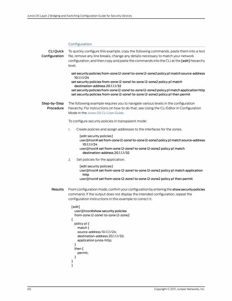
Configuration
CLI QuickConfiguration
To quickly configure this example, copy the following commands, paste them into a text
file, remove any line breaks, change any details necessary to match your network
configuration, and then copy and paste the commands into the CLI at the [edit]hierarchy
level.
set securitypolicies from-zone l2-zone1 to-zone l2-zone2policyp1matchsource-address10.1.1.1/24
set security policies from-zone l2-zone1 to-zone l2-zone2 policy p1matchdestination-address 20.1.1.1/32
setsecuritypolicies from-zone l2-zone1 to-zone l2-zone2policyp1matchapplicationhttpset security policies from-zone l2-zone1 to-zone l2-zone2 policy p1 then permit
Step-by-StepProcedure
The following example requires you to navigate various levels in the configuration
hierarchy. For instructions on how to do that, see Using the CLI Editor in Configuration
Mode in the Junos OS CLI User Guide.
To configure security policies in transparent mode:
1. Create policies and assign addresses to the interfaces for the zones.
[edit security policies]user@host#set from-zone l2-zone1 to-zone l2-zone2policyp1matchsource-address10.1.1.1/24
user@host# set from-zone l2-zone1 to-zone l2-zone2 policy p1matchdestination-address 20.1.1.1/32
2. Set policies for the application.
[edit security policies]user@host# set from-zone l2-zone1 to-zone l2-zone2 policy p1match applicationhttp
user@host# set from-zone l2-zone1 to-zone l2-zone2 policy p1 then permit
Results From configuration mode, confirm your configuration by entering the showsecuritypolicies
command. If the output does not display the intended configuration, repeat the
configuration instructions in this example to correct it.
[edit]user@host#show security policiesfrom-zone l2-zone1 to-zone l2-zone2
{policy p1 {match {source-address 10.1.1.1/24;destination-address 20.1.1.1/32;application junos-http;
}then {permit;
}}}
Copyright © 2011, Juniper Networks, Inc.60
Junos OS Layer 2 Bridging and Switching Configuration Guide for Security Devices
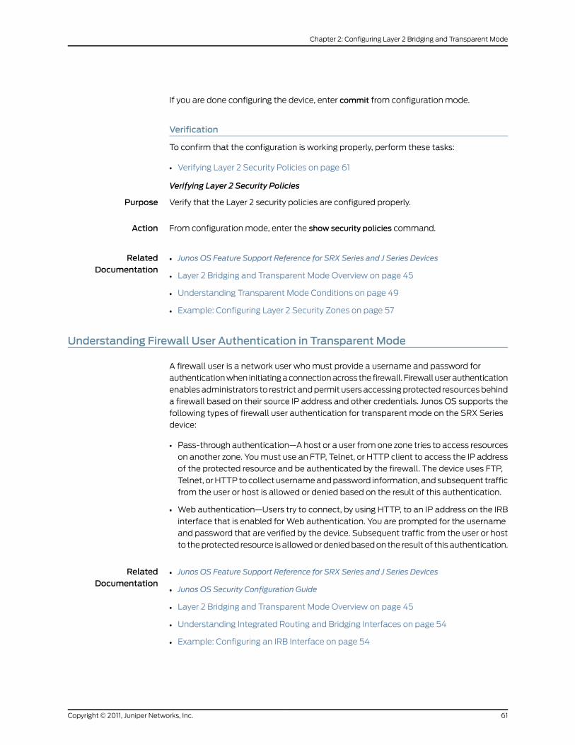
If you are done configuring the device, enter commit from configuration mode.
Verification
To confirm that the configuration is working properly, perform these tasks:
• Verifying Layer 2 Security Policies on page 61
Verifying Layer 2 Security Policies
Purpose Verify that the Layer 2 security policies are configured properly.
Action From configuration mode, enter the show security policies command.
RelatedDocumentation
Junos OS Feature Support Reference for SRX Series and J Series Devices•
• Layer 2 Bridging and Transparent Mode Overview on page 45
• Understanding Transparent Mode Conditions on page 49
• Example: Configuring Layer 2 Security Zones on page 57
Understanding Firewall User Authentication in Transparent Mode
A firewall user is a network user who must provide a username and password for
authentication when initiating a connection across the firewall. Firewall user authentication
enables administrators to restrict and permit users accessing protected resources behind
a firewall based on their source IP address and other credentials. Junos OS supports the
following types of firewall user authentication for transparent mode on the SRX Series
device:
• Pass-through authentication—A host or a user from one zone tries to access resources
on another zone. You must use an FTP, Telnet, or HTTP client to access the IP address
of the protected resource and be authenticated by the firewall. The device uses FTP,
Telnet, or HTTP to collect username and password information, and subsequent traffic
from the user or host is allowed or denied based on the result of this authentication.
• Web authentication—Users try to connect, by using HTTP, to an IP address on the IRB
interface that is enabled for Web authentication. You are prompted for the username
and password that are verified by the device. Subsequent traffic from the user or host
to the protected resource is allowed or denied based on the result of this authentication.
RelatedDocumentation
Junos OS Feature Support Reference for SRX Series and J Series Devices•
• Junos OS Security Configuration Guide
• Layer 2 Bridging and Transparent Mode Overview on page 45
• Understanding Integrated Routing and Bridging Interfaces on page 54
• Example: Configuring an IRB Interface on page 54
61Copyright © 2011, Juniper Networks, Inc.
Chapter 2: Configuring Layer 2 Bridging and Transparent Mode
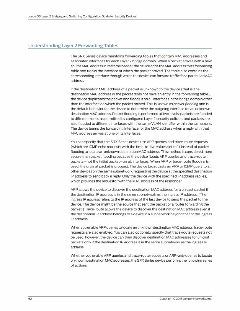
Understanding Layer 2 Forwarding Tables
The SRX Series device maintains forwarding tables that contain MAC addresses and
associated interfaces for each Layer 2 bridge domain. When a packet arrives with a new
source MAC address in its frame header, the device adds the MAC address to its forwarding
table and tracks the interface at which the packet arrived. The table also contains the
corresponding interface through which the device can forward traffic for a particular MAC
address.
If the destination MAC address of a packet is unknown to the device (that is, the
destination MAC address in the packet does not have an entry in the forwarding table),
the device duplicates the packet and floods it on all interfaces in the bridge domain other
than the interface on which the packet arrived. This is known as packet flooding and is
the default behavior for the device to determine the outgoing interface for an unknown
destination MAC address. Packet flooding is performed at two levels: packets are flooded
to different zones as permitted by configured Layer 2 security policies, and packets are
also flooded to different interfaces with the same VLAN identifier within the same zone.
The device learns the forwarding interface for the MAC address when a reply with that
MAC address arrives at one of its interfaces.
You can specify that the SRX Series device use ARP queries and trace-route requests
(which are ICMP echo requests with the time-to-live values set to 1) instead of packet
flooding to locate an unknown destination MAC address. This method is considered more
secure than packet flooding because the device floods ARP queries and trace-route
packets—not the initial packet—on all interfaces. When ARP or trace-route flooding is
used, the original packet is dropped. The device broadcasts an ARP or ICMP query to all
other devices on the same subnetwork, requesting the device at the specified destination
IP address to send back a reply. Only the device with the specified IP address replies,
which provides the requestor with the MAC address of the responder.
ARP allows the device to discover the destination MAC address for a unicast packet if
the destination IP address is in the same subnetwork as the ingress IP address. (The
ingress IP address refers to the IP address of the last device to send the packet to the
device. The device might be the source that sent the packet or a router forwarding the
packet.) Trace-route allows the device to discover the destination MAC address even if
the destination IP address belongs to a device in a subnetwork beyond that of the ingress
IP address.
When you enable ARP queries to locate an unknown destination MAC address, trace-route
requests are also enabled. You can also optionally specify that trace-route requests not
be used; however, the device can then discover destination MAC addresses for unicast
packets only if the destination IP address is in the same subnetwork as the ingress IP
address.
Whether you enable ARP queries and trace-route requests or ARP-only queries to locate
unknown destination MAC addresses, the SRX Series device performs the following series
of actions:
Copyright © 2011, Juniper Networks, Inc.62
Junos OS Layer 2 Bridging and Switching Configuration Guide for Security Devices
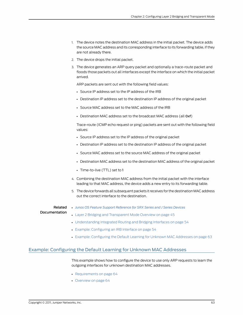
1. The device notes the destination MAC address in the initial packet. The device adds
the source MAC address and its corresponding interface to its forwarding table, if they
are not already there.
2. The device drops the initial packet.
3. The device generates an ARP query packet and optionally a trace-route packet and
floods those packets out all interfaces except the interface on which the initial packet
arrived.
ARP packets are sent out with the following field values:
• Source IP address set to the IP address of the IRB
• Destination IP address set to the destination IP address of the original packet
• Source MAC address set to the MAC address of the IRB
• Destination MAC address set to the broadcast MAC address (all 0xf)
Trace-route (ICMP echo request or ping) packets are sent out with the following field
values:
• Source IP address set to the IP address of the original packet
• Destination IP address set to the destination IP address of the original packet
• Source MAC address set to the source MAC address of the original packet
• Destination MAC address set to the destination MAC address of the original packet
• Time-to-live (TTL) set to 1
4. Combining the destination MAC address from the initial packet with the interface
leading to that MAC address, the device adds a new entry to its forwarding table.
5. The device forwards all subsequent packets it receives for the destination MAC address
out the correct interface to the destination.
RelatedDocumentation
Junos OS Feature Support Reference for SRX Series and J Series Devices•
• Layer 2 Bridging and Transparent Mode Overview on page 45
• Understanding Integrated Routing and Bridging Interfaces on page 54
• Example: Configuring an IRB Interface on page 54
• Example: Configuring the Default Learning for Unknown MAC Addresses on page 63
Example: Configuring the Default Learning for UnknownMACAddresses
This example shows how to configure the device to use only ARP requests to learn the
outgoing interfaces for unknown destination MAC addresses.
• Requirements on page 64
• Overview on page 64
63Copyright © 2011, Juniper Networks, Inc.
Chapter 2: Configuring Layer 2 Bridging and Transparent Mode

• Configuration on page 64
• Verification on page 64
Requirements
Before you begin, determine the MAC addresses and associated interfaces of the
forwarding table. See “Understanding Layer 2 Forwarding Tables” on page 62.
Overview
In this example, you configure the device to use only ARP queries without trace-route
requests.
Configuration
Step-by-StepProcedure
To configure the device to use only ARP requests to learn unknown destination MAC
addresses:
1. Enable the device.
[edit]user@host# set security flow bridge no-packet-flooding no-trace-route
2. If you are done configuring the device, commit the configuration.
[edit]user@host# commit
Verification
To verify the configuration is working properly, enter the show security flow command.
RelatedDocumentation
Junos OS Feature Support Reference for SRX Series and J Series Devices•
• Layer 2 Bridging and Transparent Mode Overview on page 45
• Understanding Integrated Routing and Bridging Interfaces on page 54
• Example: Configuring an IRB Interface on page 54
Understanding Layer 2 Transparent Mode Chassis Clusters
A pair of SRX Series devices in Layer 2 transparent mode can be connected in a chassis
cluster to provide network node redundancy. When configured in a chassis cluster, one
node acts as the primary device and the other as the secondary device, ensuring stateful
failover of processes and services in the event of system or hardware failure. If the primary
device fails, the secondary device takes over processing of traffic.
NOTE: If theprimarydevice fails inaLayer2 transparentmodechassiscluster,the physical ports in the failed device become inactive (go down) for a fewseconds before they become active (come up) again.
Copyright © 2011, Juniper Networks, Inc.64
Junos OS Layer 2 Bridging and Switching Configuration Guide for Security Devices
To form a chassis cluster, a pair of the same kind of supported SRX Series devices
combines to act as a single system that enforces the same overall security.
Devices in Layer 2 transparent mode can be deployed in active/backup and active/active
chassis cluster configurations.
The following chassis cluster features are not supported for devices in Layer 2 transparent
mode:
• Gratuitous ARP—The newly elected master in a redundancy group cannot send
gratuitous ARP requests to notify network devices of a change in mastership on the
redundant Ethernet interface links.
• IP address monitoring—Failure of an upstream device cannot be detected.
A redundancy group is a construct that includes a collection of objects on both nodes. A
redundancy group is primary on one node and backup on the other. When a redundancy
group is primary on a node, its objects on that node are active. When a redundancy group
fails over, all its objects fail over together.
You can create one or more redundancy groups numbered 1 through 128 for an
active/active chassis cluster configuration. Each redundancy group contains one or more
redundant Ethernet interfaces. A redundant Ethernet interface is a pseudointerface that
contains physical interfaces from each node of the cluster. The physical interfaces in a
redundant Ethernet interface must be the same kind—either Fast Ethernet or Gigabit
Ethernet. If a redundancy group is active on node 0, then the child links of all associated
redundant Ethernet interfaces on node 0 are active. If the redundancy group fails over
to the node 1, then the child links of all redundant Ethernet interfaces on node 1 become
active.
NOTE: In the active/active chassis cluster configuration, themaximumnumber of redundancy groups is equal to the number of redundant Ethernetinterfaces that you configure. In the active/backup chassis clusterconfiguration, themaximumnumberof redundancygroupssupported is two.
Configuring redundant Ethernet interfaces on a device in Layer 2 transparent mode is
similar to configuring redundant Ethernet interfaces on a device in Layer 3 route mode,
with the following difference: the redundant Ethernet interface on a device in Layer 2
transparent mode is configured as a Layer 2 logical interface.
The redundant Ethernet interface may be configured as either an access interface (with
a single VLAN ID assigned to untagged packets received on the interface) or as a trunk
interface (with a list of VLAN IDs accepted on the interface and, optionally, a native-vlan-id
for untagged packets received on the interface). Physical interfaces (one from each node
in the chassis cluster) are bound as child interfaces to the parent redundant Ethernet
interface.
In Layer 2 transparent mode, MAC learning is based on the redundant Ethernet interface.
The MAC table is synchronized across redundant Ethernet interfaces and Services
Processing Units (SPUs) between the pair of chassis cluster devices.
65Copyright © 2011, Juniper Networks, Inc.
Chapter 2: Configuring Layer 2 Bridging and Transparent Mode
The IRB interface is used only for management traffic, and it cannot be assigned to any
redundant Ethernet interface or redundancy group.
All Junos OS screen options that are available for a single, nonclustered device are
available for devices in Layer 2 transparent mode chassis clusters.
NOTE: Spanning-tree protocols are not supported for Layer 2 transparentmode. You should ensure that there are no loop connections in thedeployment topology.
RelatedDocumentation
Junos OS Feature Support Reference for SRX Series and J Series Devices•
• Junos OS Security Configuration Guide
• Layer 2 Bridging and Transparent Mode Overview on page 45
• Understanding Layer 2 Interfaces on page 50
• Example: Configuring Layer 2 Logical Interfaces on page 51
• Understanding Transparent Mode Conditions on page 49
• Example: Configuring Redundant Ethernet Interfaces for Layer 2 Transparent Mode
Chassis Clusters on page 66
• Understanding Layer 2 Forwarding Tables on page 62
Example: Configuring Redundant Ethernet Interfaces for Layer 2 Transparent ModeChassis Clusters
This example shows how to configure a redundant Ethernet interface on a device as a
Layer 2 logical interface for a Layer 2 transparent mode chassis cluster.
• Requirements on page 66
• Overview on page 66
• Configuration on page 67
• Verification on page 67
Requirements
Before you begin, determine the devices you want to connect in a chassis cluster. See
“Understanding Layer 2 Transparent Mode Chassis Clusters” on page 64.
Overview
This example shows you how to configure the redundant Ethernet interface as a Layer
2 logical interface and how to bind the physical interfaces (one from each node in the
chassis cluster) to the redundant Ethernet interface. In this example, you create redundant
Ethernet interface reth0 for redundancy group 1 and configure reth0 as an access interface
with the VLAN identifier 1. Then you assign physical interface ge-2/0/2 on a chassis cluster
node to the redundant Ethernet interface reth0.
Copyright © 2011, Juniper Networks, Inc.66
Junos OS Layer 2 Bridging and Switching Configuration Guide for Security Devices
Configuration
Step-by-StepProcedure
The following example requires you to navigate various levels in the configuration
hierarchy. For instructions on how to do that, see Using the CLI Editor in Configuration
Mode in the Junos OS CLI User Guide.
To configure a redundant Ethernet interface as a Layer 2 logical interface:
1. Configure the interfaces and redundancy group.
[edit interfaces]user@host# set reth0 redundant-ether-options redundancy-group 1user@host# set reth0 unit 0 family bridge interface-mode access vlan-id 1
2. Assign a physical interface on a chassis cluster node.
[edit interfaces]user@host# set ge-2/0/2 gigether-options redundant-parent reth0
3. If you are done configuring the device, commit the configuration.
[edit]user@host# commit
Verification
To verify the configuration is working properly, enter the show interfaces reth0 and show
interfaces ge-2/0/2 commands.
RelatedDocumentation
Junos OS Feature Support Reference for SRX Series and J Series Devices•
• Junos OS Security Configuration Guide
• Layer 2 Bridging and Transparent Mode Overview on page 45
• Understanding Transparent Mode Conditions on page 49
• Understanding Layer 2 Transparent Mode Chassis Clusters on page 64
• Understanding Layer 2 Forwarding Tables on page 62
Transparent Mode Devices
This topic includes the following sections:
• Class of Service Functions in Transparent Mode Overview on page 68
• Understanding BA Traffic Classification on Transparent Mode Devices on page 68
• Example: Configuring BA Classifiers on Transparent Mode Devices on page 69
• Understanding Rewrite of Packet Headers on Transparent Mode Devices on page 71
• Example: Configuring Rewrite Rules on Transparent Mode Devices on page 72
67Copyright © 2011, Juniper Networks, Inc.
Chapter 2: Configuring Layer 2 Bridging and Transparent Mode
Class of Service Functions in Transparent Mode Overview
Devices operating in Layer 2 transparent mode support the following class-of-service
(CoS) functions:
• IEEE 802.1p behavior aggregate (BA) classifiers to determine the forwarding treatment
for packets entering the device
NOTE: Only IEEE 802.1p BA classifier types are supported on devicesoperating in transparent mode.
• Rewrite rules to redefine IEEE 802.1 CoS values in outgoing packets
NOTE: Rewrite rules that redefine IP precedence CoS values andDifferentiated Services Code Point (DSCP) CoS values are not supportedon devices operating in transparent mode.
• Shapers to apply rate limiting to an interface
• Schedulers that define the properties of an output queue
You configure BA classifiers and rewrite rules on transparent mode devices in the same
way as on devices operating in Layer 3 mode. For transparent mode devices, however,
you apply BA classifiers and rewrite rules only to logical interfaces configured with the
family bridge configuration statement.
Understanding BA Traffic Classification on Transparent Mode Devices
A BA classifier checks the header information of an ingress packet. The resulting traffic
classification consists of a forwarding class (FC) and packet loss priority (PLP). The FC
and PLP associated with a packet specify the CoS behavior of a hop within the system.
For example, a hop can place a packet into a priority queue according to its FC, and
manage queues by checking the packet's PLP. Junos OS supports up to eight FCs and
four PLPs.
NOTE: MPLS EXP bit-based traffic classification is not supported.
BA classification can be applied within one DiffServ domain. BA classification can also
be applied between two domains, where each domain honors the CoS results generated
by the other domain. Junos OS performs BA classification for a packet by examining its
Layer 2 and Layer 3 CoS-related parameters. Those parameters include the following:
• Layer 2—IEEE 802.1p: User Priority
• Layer 3—IPv4 Precedence, IPv4 DSCP, IPv6 DSCP
On SRX Series devices in transparent mode, a BA classifier evaluates only Layer 2
parameters. On SRX Series devices in Layer 3 mode, a BA classifier can evaluate Layer
Copyright © 2011, Juniper Networks, Inc.68
Junos OS Layer 2 Bridging and Switching Configuration Guide for Security Devices
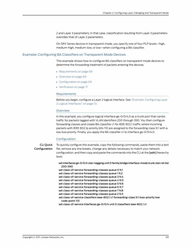
2 and Layer 3 parameters; in that case, classification resulting from Layer 3 parameters
overrides that of Layer 2 parameters.
On SRX Series devices in transparent mode, you specify one of four PLP levels—high,
medium-high, medium-low, or low—when configuring a BA classifier.
Example: Configuring BA Classifiers on Transparent Mode Devices
This example shows how to configure BA classifiers on transparent mode devices to
determine the forwarding treatment of packets entering the devices.
• Requirements on page 69
• Overview on page 69
• Configuration on page 69
• Verification on page 71
Requirements
Before you begin, configure a Layer 2 logical interface. See “Example: Configuring Layer
2 Logical Interfaces” on page 51.
Overview
In this example, you configure logical interface ge-0/0/4.0 as a trunk port that carries
traffic for packets tagged with VLAN identifiers 200 through 390. You then configure
forwarding classes and create BA classifier c1 for IEEE 802.1 traffic where incoming
packets with IEEE 802.1p priority bits 110 are assigned to the forwarding class fc1 with a
low loss priority. Finally, you apply the BA classifier c1 to interface ge-0/0/4.0.
Configuration
CLI QuickConfiguration
To quickly configure this example, copy the following commands, paste them into a text
file, remove any line breaks, change any details necessary to match your network
configuration, and then copy and paste the commands into the CLI at the [edit]hierarchy
level.
set interfacesge-0/0/4vlan-taggingunit0 familybridge interface-modetrunkvlan-id-list200-390
set class-of-service forwarding-classes queue 0 fc1set class-of-service forwarding-classes queue 1 fc2set class-of-service forwarding-classes queue 3 fc4set class-of-service forwarding-classes queue 4 fc5set class-of-service forwarding-classes queue 5 fc6set class-of-service forwarding-classes queue 6 fc7set class-of-service forwarding-classes queue 7 fc8set class-of-service forwarding-classes queue 2 fc3set class-of-service classifiers ieee-802.1 c1 forwarding-class fc1 loss-priority lowcode-point 110
set class-of-service interfaces ge-0/0/4 unit 0 classifiers ieee-802.1 c1
69Copyright © 2011, Juniper Networks, Inc.
Chapter 2: Configuring Layer 2 Bridging and Transparent Mode
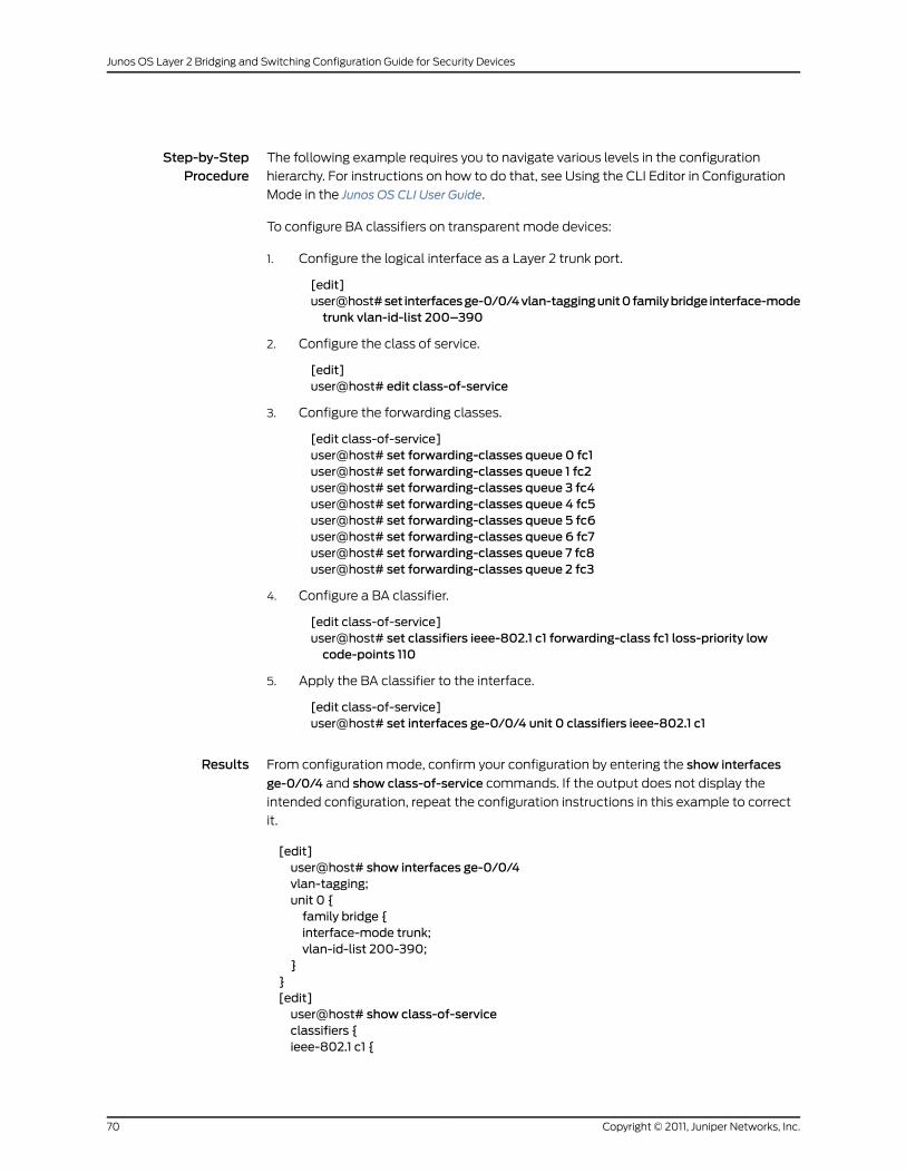
Step-by-StepProcedure
The following example requires you to navigate various levels in the configuration
hierarchy. For instructions on how to do that, see Using the CLI Editor in Configuration
Mode in the Junos OS CLI User Guide.
To configure BA classifiers on transparent mode devices:
1. Configure the logical interface as a Layer 2 trunk port.
[edit]user@host#set interfacesge-0/0/4vlan-taggingunit0familybridge interface-modetrunk vlan-id-list 200–390
2. Configure the class of service.
[edit]user@host# edit class-of-service
3. Configure the forwarding classes.
[edit class-of-service]user@host# set forwarding-classes queue 0 fc1user@host# set forwarding-classes queue 1 fc2user@host# set forwarding-classes queue 3 fc4user@host# set forwarding-classes queue 4 fc5user@host# set forwarding-classes queue 5 fc6user@host# set forwarding-classes queue 6 fc7user@host# set forwarding-classes queue 7 fc8user@host# set forwarding-classes queue 2 fc3
4. Configure a BA classifier.
[edit class-of-service]user@host# set classifiers ieee-802.1 c1 forwarding-class fc1 loss-priority lowcode-points 110
5. Apply the BA classifier to the interface.
[edit class-of-service]user@host# set interfaces ge-0/0/4 unit 0 classifiers ieee-802.1 c1
Results From configuration mode, confirm your configuration by entering the show interfaces
ge-0/0/4 and show class-of-service commands. If the output does not display the
intended configuration, repeat the configuration instructions in this example to correct
it.
[edit]user@host# show interfaces ge-0/0/4vlan-tagging;unit 0 {family bridge {interface-mode trunk;vlan-id-list 200-390;
}}[edit]user@host# show class-of-serviceclassifiers {ieee-802.1 c1 {
Copyright © 2011, Juniper Networks, Inc.70
Junos OS Layer 2 Bridging and Switching Configuration Guide for Security Devices

forwarding-class fc1 {loss-priority low code-points 110;}
}}forwarding-classes {queue 0 fc1;queue 1 fc2;queue 3 fc4;queue 4 fc5;queue 5 fc6;queue 6 fc7;queue 7 fc8;queue 2 fc3;}interfaces {ge-0/0/4 {
unit 0 {classifiers {ieee-802.1 c1;
}}
}}
If you are done configuring the device, enter commit from configuration mode.
Verification
To confirm that the configuration is working properly, perform this task:
• Verifying BA Classifiers on Transparent Mode Devices on page 71
Verifying BA Classifiers on Transparent Mode Devices
Purpose Verify that the BA classifier was configured on the transparent mode devices properly.
Action From configuration mode, enter the show interfaces ge-0/0/4 and show class-of-service
commands.
Understanding Rewrite of Packet Headers on Transparent Mode Devices
Before a packet is transmitted from an interface, the CoS fields in the packet's header
can be rewritten for the forwarding class (FC) and packet loss priority (PLP) of the packet.
The rewriting function converts a packet's FC and PLP into corresponding CoS fields in
the packet header. In Layer 2 transparent mode, the CoS fields are the IEEE 802.1p priority
bits.
71Copyright © 2011, Juniper Networks, Inc.
Chapter 2: Configuring Layer 2 Bridging and Transparent Mode

Example: Configuring Rewrite Rules on Transparent Mode Devices
This example shows how to configure rewrite rules on transparent mode devices to
redefine IEEE 802.1 CoS values in outgoing packets.
• Requirements on page 72
• Overview on page 72
• Configuration on page 72
• Verification on page 74
Requirements
Before you begin, configure a Layer 2 logical interface. See “Example: Configuring Layer
2 Logical Interfaces” on page 51.
Overview
In this example, you configure logical interface ge-1/0/3.0 as a trunk port that carries
traffic for packets tagged with VLAN identifiers 200 through 390. You then configure the
forwarding classes and create rewrite rule rw1 for IEEE 802.1 traffic. For outgoing packets
in the forwarding class fc1 with low loss priority, the IEEE 802.1p priority bits are rewritten
as 011. Finally, you apply the rewrite rule rw1 to interface ge-1/0/3.0.
Configuration
CLI QuickConfiguration
To quickly configure this example, copy the following commands, paste them into a text
file, remove any line breaks, change any details necessary to match your network
configuration, and then copy and paste the commands into the CLI at the [edit]hierarchy
level.
set interfacesge-1/0/3vlan-taggingunit0familybridge interface-modetrunkvlan-id-list200-390
set class-of-service forwarding-classes queue 0 fc1set class-of-service forwarding-classes queue 1 fc2set class-of-service forwarding-classes queue 3 fc4set class-of-service forwarding-classes queue 4 fc5set class-of-service forwarding-classes queue 5 fc6set class-of-service forwarding-classes queue 6 fc7set class-of-service forwarding-classes queue 7 fc8set class-of-service forwarding-classes queue 2 fc3set class-of-service rewrite-rules ieee-802.1 rw1 forwarding-class fc1 loss-priority lowcode-point 011
set class-of-service interfaces ge-1/0/3 unit 0 rewrite-rules ieee-802.1 rw1
Step-by-StepProcedure
The following example requires you to navigate various levels in the configuration
hierarchy. For instructions on how to do that, see Using the CLI Editor in Configuration
Mode in the Junos OS CLI User Guide.
To configure rewrite rules on transparent mode devices:
1. Configure the logical interface as a Layer 2 trunk port.
[edit]
Copyright © 2011, Juniper Networks, Inc.72
Junos OS Layer 2 Bridging and Switching Configuration Guide for Security Devices
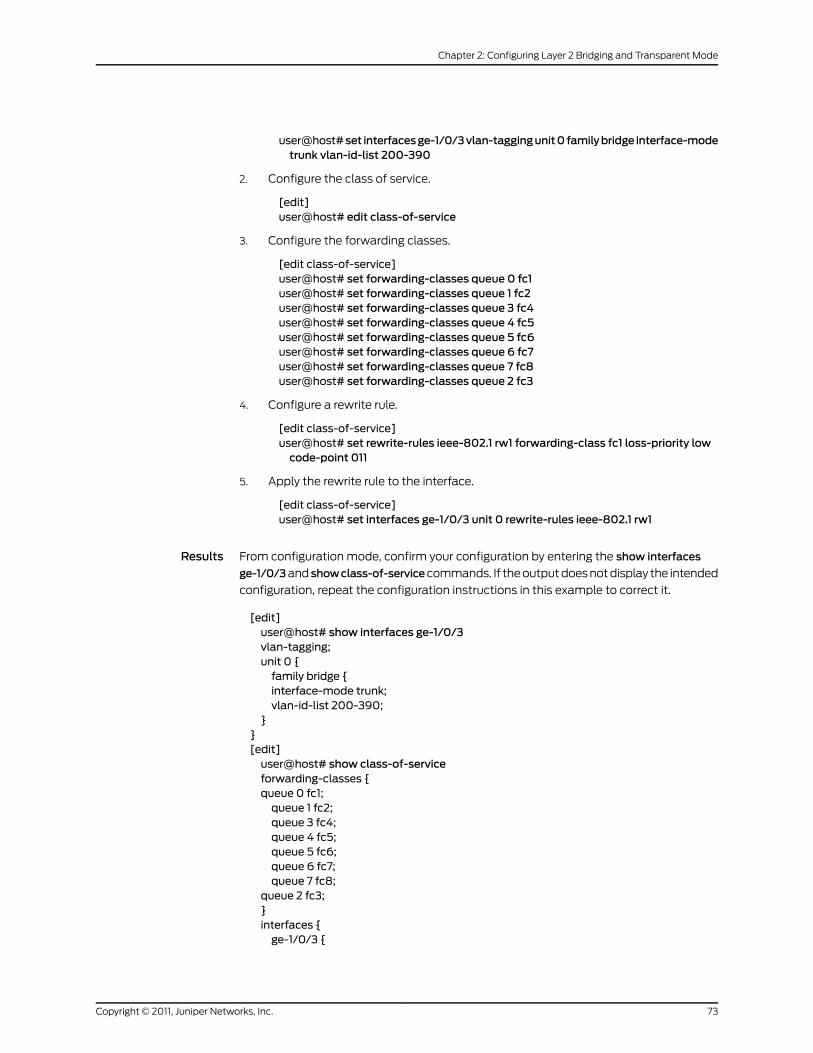
user@host#set interfacesge-1/0/3vlan-taggingunit0familybridge interface-modetrunk vlan-id-list 200-390
2. Configure the class of service.
[edit]user@host# edit class-of-service
3. Configure the forwarding classes.
[edit class-of-service]user@host# set forwarding-classes queue 0 fc1user@host# set forwarding-classes queue 1 fc2user@host# set forwarding-classes queue 3 fc4user@host# set forwarding-classes queue 4 fc5user@host# set forwarding-classes queue 5 fc6user@host# set forwarding-classes queue 6 fc7user@host# set forwarding-classes queue 7 fc8user@host# set forwarding-classes queue 2 fc3
4. Configure a rewrite rule.
[edit class-of-service]user@host# set rewrite-rules ieee-802.1 rw1 forwarding-class fc1 loss-priority lowcode-point 011
5. Apply the rewrite rule to the interface.
[edit class-of-service]user@host# set interfaces ge-1/0/3 unit 0 rewrite-rules ieee-802.1 rw1
Results From configuration mode, confirm your configuration by entering the show interfaces
ge-1/0/3and showclass-of-servicecommands. If the output does not display the intended
configuration, repeat the configuration instructions in this example to correct it.
[edit]user@host# show interfaces ge-1/0/3vlan-tagging;unit 0 {family bridge {interface-mode trunk;vlan-id-list 200-390;
}}[edit]user@host# show class-of-serviceforwarding-classes {queue 0 fc1;queue 1 fc2;queue 3 fc4;queue 4 fc5;queue 5 fc6;queue 6 fc7;queue 7 fc8;
queue 2 fc3;}interfaces {ge-1/0/3 {
73Copyright © 2011, Juniper Networks, Inc.
Chapter 2: Configuring Layer 2 Bridging and Transparent Mode
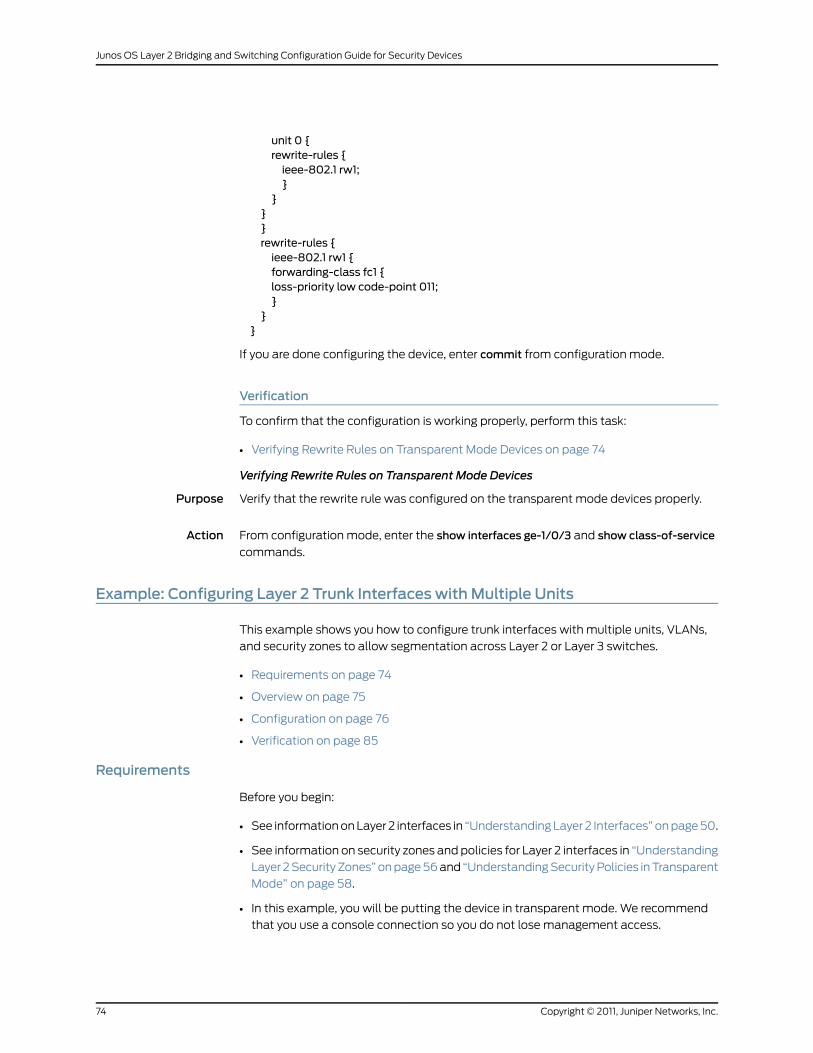
unit 0 {rewrite-rules {ieee-802.1 rw1;}
}}}rewrite-rules {ieee-802.1 rw1 {forwarding-class fc1 {loss-priority low code-point 011;}
}}
If you are done configuring the device, enter commit from configuration mode.
Verification
To confirm that the configuration is working properly, perform this task:
• Verifying Rewrite Rules on Transparent Mode Devices on page 74
Verifying Rewrite Rules on Transparent Mode Devices
Purpose Verify that the rewrite rule was configured on the transparent mode devices properly.
Action From configuration mode, enter the show interfaces ge-1/0/3 and show class-of-service
commands.
Example: Configuring Layer 2 Trunk Interfaces with Multiple Units
This example shows you how to configure trunk interfaces with multiple units, VLANs,
and security zones to allow segmentation across Layer 2 or Layer 3 switches.
• Requirements on page 74
• Overview on page 75
• Configuration on page 76
• Verification on page 85
Requirements
Before you begin:
• See information on Layer 2 interfaces in “Understanding Layer 2 Interfaces” on page 50.
• See information on security zones and policies for Layer 2 interfaces in “Understanding
Layer 2 Security Zones” on page 56 and “Understanding Security Policies in Transparent
Mode” on page 58.
• In this example, you will be putting the device in transparent mode. We recommend
that you use a console connection so you do not lose management access.
Copyright © 2011, Juniper Networks, Inc.74
Junos OS Layer 2 Bridging and Switching Configuration Guide for Security Devices

Overview
In this example, you configure an SRX Series Services Gateway in transparent mode that
sits between two EX Series Switches. Each switch is connected to the services gateway
using Gigabit Ethernet interfaces in trunk mode, while a third trunk port on the services
gateway connects to a router that is configured as the gateway to the Internet or to an
untrust zone. The trunk interfaces are also configured with multiple units, which are then
broken up into multiple VLANs and zones to provide proper segmentation between
VLANs.
You will first configure the interfaces, bridge domains, trunk interfaces, VLANs, and
security zones as shown in Figure 1 on page 76. You then apply a policy between the trust
and untrust zones. Although this example does not cover redundancy, you should configure
an HA scenario if high availability is required. For more information, see the Chassis Cluster
chapter in the Junos OS Security Configuration Guide.
NOTE: You can use this configuration with Layer 2 or Layer 3 switches. Themain difference would be that with Layer 2 switches you would run STP toavoid loops; for Layer 3, youmight want to run OSPF.
75Copyright © 2011, Juniper Networks, Inc.
Chapter 2: Configuring Layer 2 Bridging and Transparent Mode
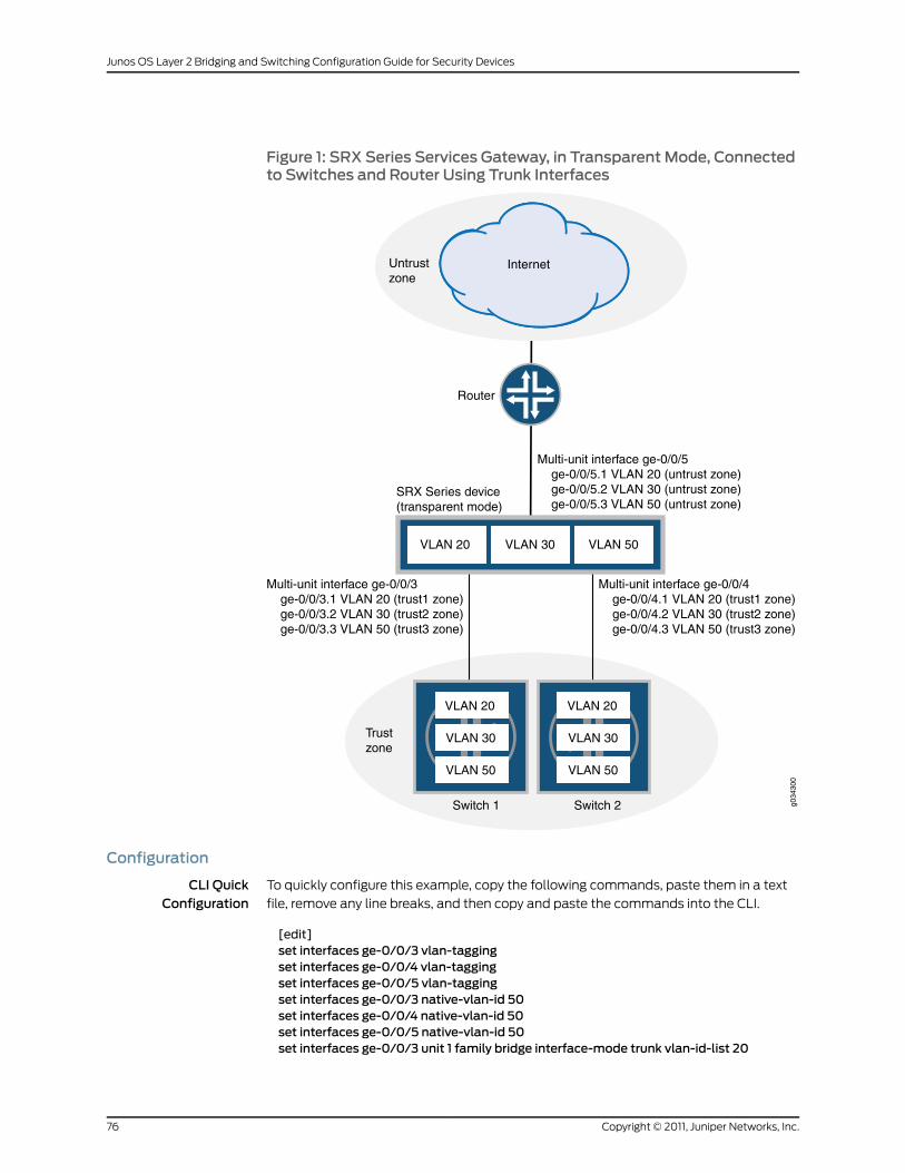
Figure 1: SRX Series Services Gateway, in Transparent Mode, Connectedto Switches and Router Using Trunk Interfaces
Router
Switch 2Switch 1
SRX Series device(transparent mode)
Multi-unit interface ge-0/0/3ge-0/0/3.1 VLAN 20 (trust1 zone)ge-0/0/3.2 VLAN 30 (trust2 zone)ge-0/0/3.3 VLAN 50 (trust3 zone)
VLAN 20 VLAN 30 VLAN 50
Untrustzone
Internet
VLAN 20
VLAN 30
VLAN 50
VLAN 20
VLAN 30
VLAN 50
Multi-unit interface ge-0/0/4ge-0/0/4.1 VLAN 20 (trust1 zone)ge-0/0/4.2 VLAN 30 (trust2 zone)ge-0/0/4.3 VLAN 50 (trust3 zone)
Multi-unit interface ge-0/0/5ge-0/0/5.1 VLAN 20 (untrust zone)ge-0/0/5.2 VLAN 30 (untrust zone)ge-0/0/5.3 VLAN 50 (untrust zone)
Trustzone
g034
300
Configuration
CLI QuickConfiguration
To quickly configure this example, copy the following commands, paste them in a text
file, remove any line breaks, and then copy and paste the commands into the CLI.
[edit]set interfaces ge-0/0/3 vlan-taggingset interfaces ge-0/0/4 vlan-taggingset interfaces ge-0/0/5 vlan-taggingset interfaces ge-0/0/3 native-vlan-id 50set interfaces ge-0/0/4 native-vlan-id 50set interfaces ge-0/0/5 native-vlan-id 50set interfaces ge-0/0/3 unit 1 family bridge interface-mode trunk vlan-id-list 20
Copyright © 2011, Juniper Networks, Inc.76
Junos OS Layer 2 Bridging and Switching Configuration Guide for Security Devices

set interfaces ge-0/0/3 unit 2 family bridge interface-mode trunk vlan-id-list 30set interfaces ge-0/0/3 unit 3 family bridge interface-mode trunk vlan-id-list 50set interfaces ge-0/0/4 unit 1 family bridge interface-mode trunk vlan-id-list 20set interfaces ge-0/0/4 unit 2 family bridge interface-mode trunk vlan-id-list 30set interfaces ge-0/0/4 unit 3 family bridge interface-mode trunk vlan-id-list 50set interfaces ge-0/0/5 unit 1 family bridge interface-mode trunk vlan-id-list 20set interfaces ge-0/0/5 unit 2 family bridge interface-mode trunk vlan-id-list 30set interfaces ge-0/0/5 unit 3 family bridge interface-mode trunk vlan-id-list 50set bridge-domains bd1 vlan-id 20set bridge-domains bd2 vlan-id 30set bridge-domains bd3 vlan-id 50set security flow bridge bypass-non-ip-unicastset security flow bridge bpdu-vlan-floodingset security zones security-zone trust1 interfaces ge-0/0/3.1 host-inbound-trafficsystem-services all
set security zones security-zone trust2 interfaces ge-0/0/3.2 host-inbound-trafficsystem-services all
set security zones security-zone trust3 interfaces ge-0/0/3.3 host-inbound-trafficsystem-services all
set security zones security-zone trust1 interfaces ge-0/0/4.1 host-inbound-trafficsystem-services all
set security zones security-zone trust2 interfaces ge-0/0/4.2 host-inbound-trafficsystem-services all
set security zones security-zone trust3 interfaces ge-0/0/4.3 host-inbound-trafficsystem-services all
set security zones security-zone untrust interfaces ge-0/0/5.1 host-inbound-trafficsystem-services all
set securitypolicies from-zone trust1 to-zoneuntrustpolicypolicy1matchsource-addressany
set security policies from-zone trust1 to-zone untrust policy policy1 matchdestination-address any
set security policies from-zone trust1 to-zone untrust policy policy1 match applicationany
set security policies from-zone trust1 to-zone untrust policy policy1 then permitsetsecuritypolicies from-zoneuntrust to-zonetrust1policypolicy2matchsource-addressany
set security policies from-zone untrust to-zone trust1 policy policy2matchdestination-address any
set security policies from-zone untrust to-zone trust1 policy policy2match applicationany
set security policies from-zone untrust to-zone trust1 policy policy2 then denysetsecuritypolicies from-zonetrust2 to-zoneuntrustpolicypolicy3matchsource-addressany
set security policies from-zone trust2 to-zone untrust policy policy3matchdestination-address any
set security policies from-zone trust2 to-zone untrust policy policy3match applicationany
set security policies from-zone trust2 to-zone untrust policy policy3 then permitsetsecuritypolicies from-zoneuntrust to-zonetrust2policypolicy4matchsource-addressany
set security policies from-zone untrust to-zone trust2 policy policy4matchdestination-address any
set security policies from-zone untrust to-zone trust2 policy policy4match applicationjunos-http
set security policies from-zone untrust to-zone trust2 policy policy4match applicationjunos-https
77Copyright © 2011, Juniper Networks, Inc.
Chapter 2: Configuring Layer 2 Bridging and Transparent Mode
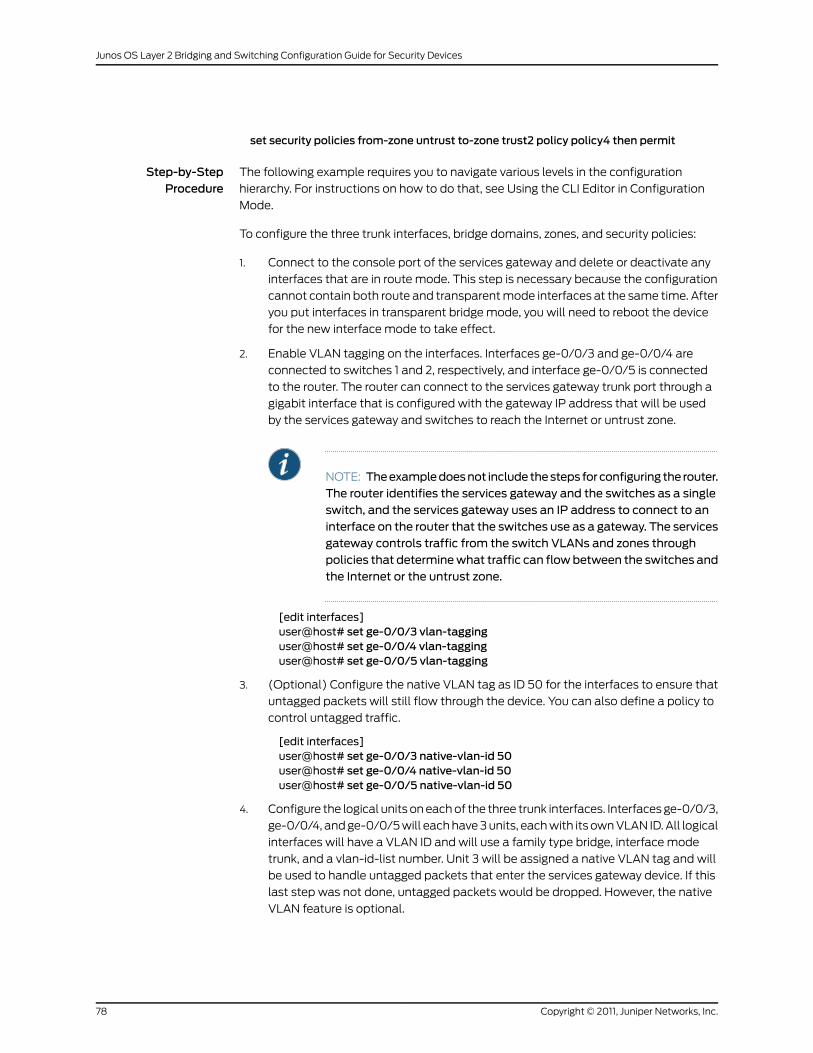
set security policies from-zone untrust to-zone trust2 policy policy4 then permit
Step-by-StepProcedure
The following example requires you to navigate various levels in the configuration
hierarchy. For instructions on how to do that, see Using the CLI Editor in Configuration
Mode.
To configure the three trunk interfaces, bridge domains, zones, and security policies:
1. Connect to the console port of the services gateway and delete or deactivate any
interfaces that are in route mode. This step is necessary because the configuration
cannot contain both route and transparent mode interfaces at the same time. After
you put interfaces in transparent bridge mode, you will need to reboot the device
for the new interface mode to take effect.
2. Enable VLAN tagging on the interfaces. Interfaces ge-0/0/3 and ge-0/0/4 are
connected to switches 1 and 2, respectively, and interface ge-0/0/5 is connected
to the router. The router can connect to the services gateway trunk port through a
gigabit interface that is configured with the gateway IP address that will be used
by the services gateway and switches to reach the Internet or untrust zone.
NOTE: Theexampledoesnot includethesteps forconfiguring the router.The router identifies the services gateway and the switches as a singleswitch, and the services gateway uses an IP address to connect to aninterface on the router that the switches use as a gateway. The servicesgateway controls traffic from the switch VLANs and zones throughpolicies that determinewhat traffic can flowbetween the switches andthe Internet or the untrust zone.
[edit interfaces]user@host# set ge-0/0/3 vlan-tagginguser@host# set ge-0/0/4 vlan-tagginguser@host# set ge-0/0/5 vlan-tagging
3. (Optional) Configure the native VLAN tag as ID 50 for the interfaces to ensure that
untagged packets will still flow through the device. You can also define a policy to
control untagged traffic.
[edit interfaces]user@host# set ge-0/0/3 native-vlan-id 50user@host# set ge-0/0/4 native-vlan-id 50user@host# set ge-0/0/5 native-vlan-id 50
4. Configure the logical units on each of the three trunk interfaces. Interfaces ge-0/0/3,
ge-0/0/4, and ge-0/0/5 will each have 3 units, each with its own VLAN ID. All logical
interfaces will have a VLAN ID and will use a family type bridge, interface mode
trunk, and a vlan-id-list number. Unit 3 will be assigned a native VLAN tag and will
be used to handle untagged packets that enter the services gateway device. If this
last step was not done, untagged packets would be dropped. However, the native
VLAN feature is optional.
Copyright © 2011, Juniper Networks, Inc.78
Junos OS Layer 2 Bridging and Switching Configuration Guide for Security Devices
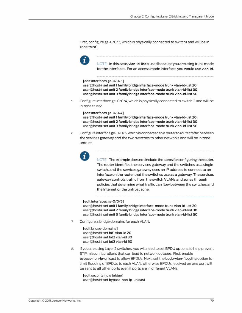
First, configure ge-0/0/3, which is physically connected to switch1 and will be in
zone trust1.
NOTE: In this case,vlan-id-list is usedbecauseyouareusing trunkmode
for the interfaces. For an accessmode interface, you would use vlan-id.
[edit interfaces ge-0/0/3]user@host# set unit 1 family bridge interface-mode trunk vlan-id-list 20user@host# set unit 2 family bridge interface-mode trunk vlan-id-list 30user@host# set unit 3 family bridge interface-mode trunk vlan-id-list 50
5. Configure interface ge-0/0/4, which is physically connected to switch 2 and will be
in zone trust2.
[edit interfaces ge-0/0/4]user@host# set unit 1 family bridge interface-mode trunk vlan-id-list 20user@host# set unit 2 family bridge interface-mode trunk vlan-id-list 30user@host# set unit 3 family bridge interface-mode trunk vlan-id-list 50
6. Configure interface ge-0/0/5, which is connected to a router to route traffic between
the services gateway and the two switches to other networks and will be in zone
untrust.
NOTE: Theexampledoesnot includethesteps forconfiguring the router.The router identifies the services gateway and the switches as a singleswitch, and the services gateway uses an IP address to connect to aninterface on the router that the switches use as a gateway. The servicesgateway controls traffic from the switch VLANs and zones throughpolicies that determinewhat traffic can flowbetween the switches andthe Internet or the untrust zone.
[edit interfaces ge-0/0/5]user@host# set unit 1 family bridge interface-mode trunk vlan-id-list 20user@host# set unit 2 family bridge interface-mode trunk vlan-id-list 30user@host# set unit 3 family bridge interface-mode trunk vlan-id-list 50
7. Configure a bridge domains for each VLAN.
[edit bridge-domains]user@host# set bd1 vlan-id 20user@host# set bd2 vlan-id 30user@host# set bd3 vlan-id 50
8. If you are using Layer 2 switches, you will need to set BPDU options to help prevent
STP misconfigurations that can lead to network outages. First, enable
bypass-non-ip-unicast to allow BPDUs. Next, set the bpdu-vlan-flooding option to
limit flooding of BPDUs to each VLAN; otherwise BPDUs received on one port will
be sent to all other ports even if ports are in different VLANs.
[edit security flow bridge]user@host# set bypass-non-ip-unicast
79Copyright © 2011, Juniper Networks, Inc.
Chapter 2: Configuring Layer 2 Bridging and Transparent Mode

user@host# set bpdu-vlan-flooding
9. Configure security zones for the logical units on ge-0/0/3, ge-0/0/4, and ge-0/0/5.
[edit security zones]user@host# set security-zone trust1 interfaces ge-0/0/3.1 host-inbound-trafficsystem-services all
user@host# set security-zone trust2 interfaces ge-0/0/3.2 host-inbound-trafficsystem-services all
user@host# set security-zone trust3 interfaces ge-0/0/3.3 host-inbound-trafficsystem-services all
user@host# set security-zone trust1 interfaces ge-0/0/4.1 host-inbound-trafficsystem-services all
user@host# set security-zone trust2 interfaces ge-0/0/4.2 host-inbound-trafficsystem-services all
user@host# set security-zone trust3 interfaces ge-0/0/4.3 host-inbound-trafficsystem-services all
user@host# set security-zone untrust interfaces ge-0/0/5.1 host-inbound-trafficsystem-services all
10. Configure a security policy named policy1 to permit all traffic from the trust1 zone
to the untrust zone.
[edit security policies from-zone trust1 to-zone untrust]user@host# set policy policy1 match source-address anyuser@host# set policy policy1 match destination-address anyuser@host# set policy policy1 match application anyuser@host# set policy policy1 then permit
11. Configure a security policy named policy2 to deny all traffic from the untrust zone
to the trust1 zone.
[edit security policies from-zone untrust to-zone trust1]user@host# set policy policy2match source-address anyuser@host# set policy policy2match destination-address anyuser@host# set policy policy2match application anyuser@host# set policy policy2 then deny
12. Configure a security policy named policy3 to permit all traffic from the trust2 zone
to the untrust zone.
[edit security policies from-zone trust2 to-zone untrust]user@host# set policy policy3match source-address anyuser@host# set policy policy3match destination-address anyuser@host# set policy policy3match application anyuser@host# set policy policy3 then permit
13. Create a security policy named policy4 to allow only HTTP and HTTPS traffic from
the untrust zone to the trust2 zone.
[edit security policies from-zone untrust to-zone trust2]user@host# set policy policy4match source-address anyuser@host# set policy policy4match destination-address anyuser@host# set policy policy4match application junos-httpuser@host# set policy policy4match application junos-httpsuser@host# set policy policy4 then permit
Copyright © 2011, Juniper Networks, Inc.80
Junos OS Layer 2 Bridging and Switching Configuration Guide for Security Devices
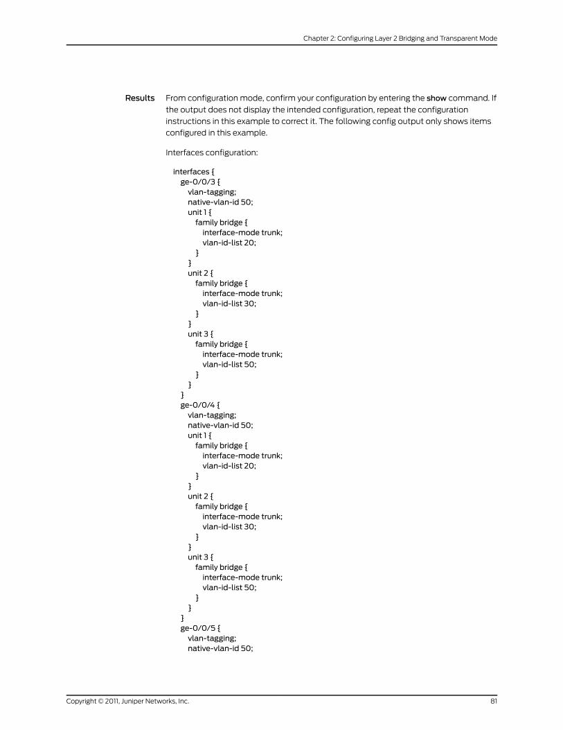
Results From configuration mode, confirm your configuration by entering the show command. If
the output does not display the intended configuration, repeat the configuration
instructions in this example to correct it. The following config output only shows items
configured in this example.
Interfaces configuration:
interfaces {ge-0/0/3 {vlan-tagging;native-vlan-id 50;unit 1 {family bridge {interface-mode trunk;vlan-id-list 20;
}}unit 2 {family bridge {interface-mode trunk;vlan-id-list 30;
}}unit 3 {family bridge {interface-mode trunk;vlan-id-list 50;
}}
}ge-0/0/4 {vlan-tagging;native-vlan-id 50;unit 1 {family bridge {interface-mode trunk;vlan-id-list 20;
}}unit 2 {family bridge {interface-mode trunk;vlan-id-list 30;
}}unit 3 {family bridge {interface-mode trunk;vlan-id-list 50;
}}
}ge-0/0/5 {vlan-tagging;native-vlan-id 50;
81Copyright © 2011, Juniper Networks, Inc.
Chapter 2: Configuring Layer 2 Bridging and Transparent Mode

unit 1 {family bridge {interface-mode trunk;vlan-id-list 20;
}}unit 2 {family bridge {interface-mode trunk;vlan-id-list 30;
}}unit 3 {family bridge {interface-mode trunk;vlan-id-list 50;
}}
}}
Bridge domains configuration:
bridge-domains {bd1 {vlan-id 20;
}bd2 {vlan-id 30;
}bd3 {vlan-id 50;
}}
Zones and policies configuration:
security {flow {bridge {bypass-non-ip-unicast;bpdu-vlan-flooding;
}}policies {from-zone trust1 to-zone untrust {policy policy1 {match {source-address any;destination-address any;application any;
}then {permit;
}}
}
Copyright © 2011, Juniper Networks, Inc.82
Junos OS Layer 2 Bridging and Switching Configuration Guide for Security Devices
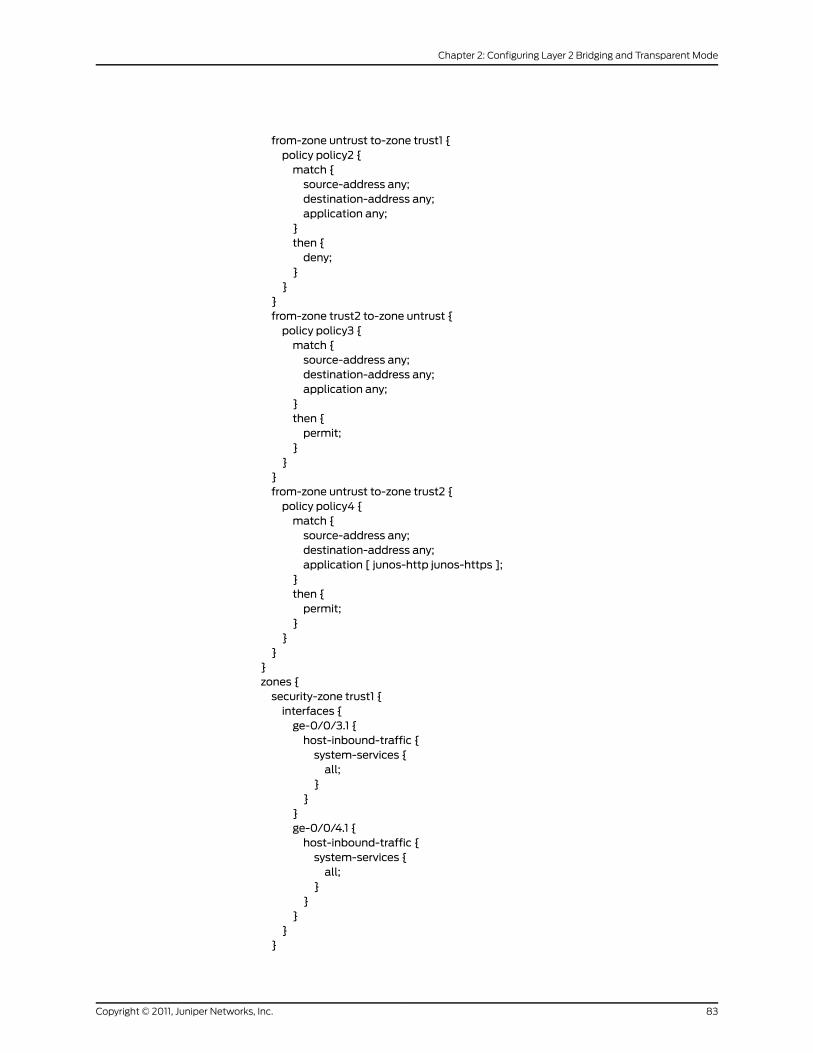
from-zone untrust to-zone trust1 {policy policy2 {match {source-address any;destination-address any;application any;
}then {deny;
}}
}from-zone trust2 to-zone untrust {policy policy3 {match {source-address any;destination-address any;application any;
}then {permit;
}}
}from-zone untrust to-zone trust2 {policy policy4 {match {source-address any;destination-address any;application [ junos-http junos-https ];
}then {permit;
}}
}}zones {security-zone trust1 {interfaces {ge-0/0/3.1 {host-inbound-traffic {system-services {all;
}}
}ge-0/0/4.1 {host-inbound-traffic {system-services {all;
}}
}}
}
83Copyright © 2011, Juniper Networks, Inc.
Chapter 2: Configuring Layer 2 Bridging and Transparent Mode

security-zone trust2 {interfaces {ge-0/0/3.2 {host-inbound-traffic {system-services {all;
}}
}ge-0/0/4.2 {host-inbound-traffic {system-services {all;
}}
}}
}security-zone trust3 {interfaces {ge-0/0/3.3 {host-inbound-traffic {system-services {all;
}}
}ge-0/0/4.3 {host-inbound-traffic {system-services {all;
}}
}}
}security-zone untrust {interfaces {ge-0/0/5.1 {host-inbound-traffic {system-services {all;
}}
}}
}}
If you are done configuring the device, enter commit from configuration mode.
Copyright © 2011, Juniper Networks, Inc.84
Junos OS Layer 2 Bridging and Switching Configuration Guide for Security Devices

Verification
Confirm that the configuration is working properly.
• Verifying the Interfaces Configuration on page 85
• Verifying Policies and Traffic Flow on page 85
Verifying the Interfaces Configuration
Purpose Verify that ge-0/0/3 is in the correct security zone and is in trunk mode.
Action From operational mode, enter the show interfaces ge-0/0/3 command.
Meaning You will see information about each logical interface for ge-0/0/3. In this case, you should
see the three logical interfaces. Verify that the Security:Zone field shows trust1 for
ge-0/0/3.1, trust2 for ge-0/0/3.2, and trust3 for ge-0/0/3.3. Also verify that the Flags:
field under Protocols bridge shows Trunk-mode for each logical interface. You can then
do the same for the other interfaces (ge-0/0/4, ge-0/0/5).
The following output shows the ge-0/0.3.1 logical interface:
Logical interface ge-0/0/3.1 (Index 68) (SNMP ifIndex 523) Flags: Device-Down SNMP-Traps 0x0 Encapsulation: Ethernet-Bridge Input packets : 0 Output packets: 0 Security: Zone: trust1 Allowed host-inbound traffic : bootp dns dhcp finger ftp tftp ident-reset http https ike netconf ping reverse-telnet reverse-ssh rlogin rpm rsh snmp snmp-trap ssh telnet traceroute xnm-clear-text xnm-ssl lsping ntp sip dhcpv6 r2cp Protocol bridge, MTU: 1518 Flags: Is-Primary, Trunk-Mode
Verifying Policies and Traffic Flow
Purpose Verify that each policy is working properly and that traffic is being allowed or denied
based on the policies that have been implemented.
Action From operational mode, enter the show security zones command.
Meaning The following output shows each security zone and the interfaces that are in those zones.
Security zone: trust1 Send reset for non-SYN session TCP packets: Off Policy configurable: Yes Interfaces bound: 2 Interfaces: ge-0/0/3.1 ge-0/0/4.1
Security zone: trust2 Send reset for non-SYN session TCP packets: Off Policy configurable: Yes Interfaces bound: 2 Interfaces:
85Copyright © 2011, Juniper Networks, Inc.
Chapter 2: Configuring Layer 2 Bridging and Transparent Mode
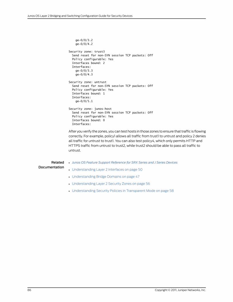
ge-0/0/3.2 ge-0/0/4.2
Security zone: trust3 Send reset for non-SYN session TCP packets: Off Policy configurable: Yes Interfaces bound: 2 Interfaces: ge-0/0/3.3 ge-0/0/4.3
Security zone: untrust Send reset for non-SYN session TCP packets: Off Policy configurable: Yes Interfaces bound: 1 Interfaces: ge-0/0/5.1
Security zone: junos-host Send reset for non-SYN session TCP packets: Off Policy configurable: Yes Interfaces bound: 0 Interfaces:
After you verify the zones, you can test hosts in those zones to ensure that traffic is flowing
correctly. For example, policy1 allows all traffic from trust1 to untrust and policy 2 denies
all traffic for untrust to trust1. You can also test policy4, which only permits HTTP and
HTTPS traffic from untrust to trust2, while trust2 should be able to pass all traffic to
untrust.
RelatedDocumentation
• Junos OS Feature Support Reference for SRX Series and J Series Devices
• Understanding Layer 2 Interfaces on page 50
• Understanding Bridge Domains on page 47
• Understanding Layer 2 Security Zones on page 56
• Understanding Security Policies in Transparent Mode on page 58
Copyright © 2011, Juniper Networks, Inc.86
Junos OS Layer 2 Bridging and Switching Configuration Guide for Security Devices

PART 2
Index
• Index on page 89
87Copyright © 2011, Juniper Networks, Inc.

Copyright © 2011, Juniper Networks, Inc.88
Junos OS Layer 2 Bridging and Switching Configuration Guide for Security Devices

Index
Symbols#, comments in configuration statements...................xiii
( ), in syntax descriptions.....................................................xiii
802.1X
configuring........................................................................28
< >, in syntax descriptions...................................................xiii
[ ], in configuration statements.........................................xiii
{ }, in configuration statements........................................xiii
| (pipe), in syntax descriptions..........................................xiii
Bbraces, in configuration statements................................xiii
brackets
angle, in syntax descriptions......................................xiii
square, in configuration statements.......................xiii
bridge domains........................................................................47
forwarding tables...........................................................62
integrated routing and bridging interface.............54
SRX Series device support.........................................46
transparent mode..........................................................45
bridging
transparent mode..........................................................45
Cchassis clusters
transparent mode.........................................................64
Class of Service
transparent mode.........................................................68
classifiers
transparent mode.........................................................68
comments, in configuration statements.......................xiii
configuring
IGMP snooping.................................................................41
LACP..............................................................................18, 21
conventions
notice icons.......................................................................xii
text and syntax.................................................................xii
CoS (class of service)
transparent mode.........................................................68
curly braces, in configuration statements.....................xiii
customer support...................................................................xiv
contacting JTAC..............................................................xiv
Ddocumentation
comments on..................................................................xiv
EEthernet ports switching
overview...............................................................................3
Ffirewall user authentication
transparent mode...........................................................61
font conventions......................................................................xii
forwarding tables
Layer 2 bridge domain..................................................62
GGVRP
configuring........................................................................43
understanding.................................................................42
Hhardware
supported platforms......................................................xii
IIGMP snooping
configuring.........................................................................41
understanding.................................................................39
IGMP Snooping
working..............................................................................39
integrated routing and bridging interface......................54
LLACP
configuring...................................................................18, 21
Layer 2 bridging
integrated routing and bridging interface.............54
multi-unit trunk interface............................................74
SRX3400, SRX3600, SRX5600, SRX5800
devices...........................................................................46
SRX3400, SRX3600, SRX5600, SRX5800
services gateways.....................................................45
Layer 2 forwarding tables....................................................62
89Copyright © 2011, Juniper Networks, Inc.
Layer 2 interfaces
security zones..................................................................56
SRX3400, SRX3600, SRX5600, and SRX5800
devices...........................................................................50
Layer 2 security zones...........................................................56
Layer 2 switching
supported devices............................................................4
Mmanuals
comments on..................................................................xiv
Nnetwork interfaces
verifying properties of uPIM switch ports................9
notice icons................................................................................xii
Pparentheses, in syntax descriptions................................xiii
ports
verifying status of uPIM ports in switching
mode.................................................................................9
Rrewrite rules
transparent mode...........................................................71
Ssecurity policies
transparent mode.........................................................58
show interfaces switch-port command...........................9
Spanning Tree Protocol
configuring..........................................................................17
understanding..................................................................13
support, technical See technical support
switching
configuring.........................................................................41
supported devices............................................................4
switching mode
verifying................................................................................9
switching modes
understanding...................................................................8
syntax conventions.................................................................xii
Ttechnical support
contacting JTAC..............................................................xiv
transparent mode
BA classifier.....................................................................68
blocking non-ARP traffic............................................58
blocking non-IP traffic.................................................58
broadcast traffic.............................................................58
chassis clusters..............................................................64
Class of Service..............................................................68
conditions.........................................................................49
firewall user authentication........................................61
multi-unit trunk interface............................................74
rewrite rules.......................................................................71
security policies..............................................................58
VLAN retagging...............................................................52
UuPIMs
verifying port status.........................................................9
user authentication
transparent mode...........................................................61
Vverification
interface properties for uPIM switches....................9
VLAN retagging
transparent mode..........................................................52
VLANs
configuring.........................................................................12
understanding..................................................................10
Copyright © 2011, Juniper Networks, Inc.90
Junos OS Layer 2 Bridging and Switching Configuration Guide for Security Devices