lawnboy d400 d600
TRANSCRIPT
FUEL TANK VENTING
D-400 SERIES FUEL SYSTEM I N S P E C T I O N
Fuel tanks must be vented to prevent vacuum forming and stop- ping flow of fuel. Tank caps have a plain vent hole. A closed vent will create a vacuum in the tank a s fuel is used - the engine will run a few minutes and stop. In a few minutes the vacuum will decrease and the engine can be started again, but it will stop again in a few minutes. The vent hole can become clogged with dirt., inspect and clean ,as required.
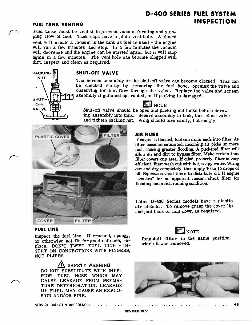
SHUT-OFF VALVE The screen assembly or the shut-of€ valve can become clogged. This can be checked easily by removing the fuel hose, opening the valve and observing for fuel flow through the valve. Replace the valve and screen assembly if gummed up, rusted, or if packing is damaged.
NOTE Shut-off valve should be open and packing nut loose before screw- ing assembly into tank. Secure assembly to tank, then close valve and tighten packing nut. Wing should turn easily, but snugly.
FUEL L I N E Inspect the fuel line, If cracked, spongy, or otherwise not f i t for good safe use, re- place. DON’T TWIST FUEL LINE - IN- SERT ON CONNECTIONS WITH FINGERS, NOT PLIERS.
SAFETY WARNING DO NOT SUBSTITUTE WITH INFE- RIOR FUEL HOSE WHICH MAY
TURE DETERIORATION. LEAKAGE OF FUEL MAY CAUSE AN EXPLO- SION AND/OR FIRE.
CAUSE LEAKAGE FROM PREMA-
AIR FILTER If engine is flooded, fuel can drain back into filter. As filter becomes saturated, incoming air picks up more fuel, causing greater flooding. A puckered filter will allow air and dirt to bypass filter. Make certain that filter covers cup area. If oiled, properly, filter is very efficient. First wash out with hot, soapy water. Wring out and dry completely, then apply 10 to 15 drops of oil. Squeeze several times to distribute oil. If engine “smokes” for no apparent reason, check filter for flooding and a rich running condition.
Later D-400 Series models have a plastic air cleaner. To remove grasp the cover lip and pull back o r fold down as required.
NOTE Reinstall filter in the same position which it was removed.
SERVICE BULLETIN REFERENCES . . . . . . . . , . , . . . , . . . . . . . . . . . . . . . . . . . . . . . . . 4-5 REVISED 1977

D-400 SERIES FUEL SYSTEM INSPECTION
NOTE Some later model D-400 engines a re equipped with the D-600 Series fuel system. A thorough visual inspec- tion will determine the fuel system used on the engine.
FLOAT VALVE
The float valve consists of a needle and seat assembly, activated with a float in the float bowl. The needle is steel with rubber tip and the seat brass, materials which will not readily adhere together. The needle rests on the float arm, (held in place by a spring clip on later models).
Operation is automatic. When the float bowl is empty, the float rests on the bottom of the bowl. As fuel enters bowl of carburetor, the float rises, moving needle into seat and shutting off fuel. As the engine uses fuel, the float drops slightly, allowing more fuel to enter bowl, maintaining a constant fuel level in bowl.
The needle and seat must be replaced as an assembly. 'They a re matched to form a perfect seal.
Some of the problems you may encounter with the float valve
Cause
GUM IN FUEL
SPRING WIRE CLIP COMES OFF
NEEDLE AND SEAT NOT MATCHED
FLOAT ARM NOT SET RIGHT
PIVOT PIN CORRODED OR BENT
FLOAT STRIKING NOZZLE
VARNISH OFF FLOAT
Effect
Stops up openings
Needle may stick shut
Fuel supply can't be shut off from float bowl
Set too high - carburetor
Set too low - carburetor floods
starves
Float sticks
Float sticks
Float soaks up fuel, chang- ing floating characteristics
are a s follows:
Remedy
*Clean out carb. with solvent
Replace Clip
Replace Needle and Seat as an Assembly
Set correctly
Set correctly
Replace Pin
Replace Float
*Replace Float
*Never allow a strong solvent to come in contact with the float. The cork float is coated with an epoxy sealer. If the solvent removes the epoxy, the float will absorb gasoline and its floating characteristics will change.
4-6 . . . , . . . . . . . . . . . . . . . . . . . . . . . . . . . . . . . . . . . . SERVICE BULLETIN REFERENCES
REVISED 1977

D - 4 0 0 SERIES CARBURETOR ADJUSTMENTS
NEEDLE ADJUSTMENT
To adjust needle, turn adjusting knob clock- wise until needle seats lightly; DO NOT FORCE NEEDLE DOWN TOO TIGHT, SINCE YOU MAY DAMAGE NEEDLE OR SEAT IN NOZZLE AND MAKE FURTHER ADJUST- MENT DIFFICULT.
Then open needle two turns. Start engine. If engine begins to die, open carburetor adjusting knob by turning counterclockwise. If engine runs roughly, close knob by turning clockwise until engine smooths out. Let engine run for about 5 minutes to warm up. Close adjusting knob slowly until engine begins to die, then open adjusting knob 1/4 to 1/2 turn.
Carburetors on earlier "D" 400 model en- On later "D" 400 model engines the low gines also contain a slow speed adjustment. speed needle adjusting valve has been re- The correct setting for this adjustment is 1 placed with a fixed jet. This jet is pressed turn open. If an engine runs ROUGH or into the low speed passage and the passage "HUNTS" at the "low" speed setting it can opening is sealed with a lead shot.
adjustment. be leveled out by opening, o r closing this
SERVICE BULLETIN REFERENCES . . . . . . ... . . . . . . . . . . . . . . . . . . . . . . . . . . . . . . . . 4-7
D-400 SERIES .CARBURETOR SERVICING
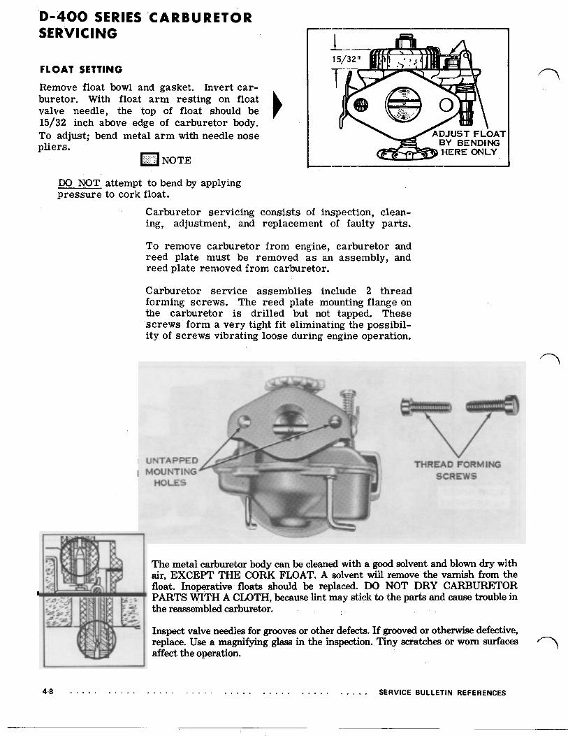
FLOAT SETTING Remove float bowl and gasket. Invert car- buretor. With float arm resting on float valve needle, the top of float should be 15/32 inch above edge of carburetor body. To adjust; bend metal a rm with needle nose pliers.
NOTE
DO NOT attempt to bend by applying pressure to cork float.
Carburetor servicing consists of inspection, clean- ing, adjustment, and replacement of faulty parts.
To remove carburetor from engine, carburetor and reed plate must be removed as an assembly,. and reed plate removed from carburetor.
Carburetor service assemblies include 2 thread forming screws. The reed plate mounting flange on the carburetor is drilled but not tapped. These screws form a very tight fit eliminating the possibil- ity of screws vibrating loose during engine operation.
MOUNTING HOLES
UNTAPPED THREAD FORMING SCREWS
The metal carburetor body can be cleaned with a good solvent and blown dry with air, EXCEPT THE CORK FLOAT. A solvent will remove the varnish from the float. Inoperative floats should be replaced. DO NOT DRY CARBURETOR PARTS WITH A CLOTH, because lint may stick to the parts and cause trouble in the reassembled carburetor.
Inspect valve needles for grooves or other defects. If grooved or otherwise defective, replace. Use a magnifying glass in the inspection. Tiny scratches or worn surfaces affect the operation.
4-8 . . . . . . . . . . . . . . . . . . . . . . . . . . . . . . . . . . . . SERVICE BULLETIN REFERENCES

D-400 SERIES CARBURETOR SERVICING
The reed plate can be cleaned with solvent with the rest of the car- buretor. Be careful in handling reeds, so as not to distort them. The
or otherwise damaged reeds cannot be repaired. Check the reed plate for warpage. DO NOT USE COMPRESSED AIR ON REEDS, The rough edge of the reed should be away from the plate.
MACHINED SURFACE
reeds must lie flat against the reed plate to form a perfect seal. Bent
Maximum clearance allowed between reed tip and reed plate is .015. If clearance exceeds this, reeds must be replaced.
SERVICE BULLETIN REFERENCES . . . . . . . . . . . . . . . . . . . . . . . . . . . . . . . . . . . . . . . . 4-9
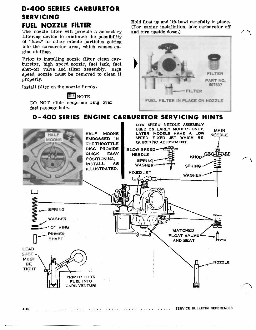
D-400 SERIES CARBURETOR S E R V I C I N G FUEL NOZZLE FILTER The nozzle filter will provide a secondary filtering device to minimize the possibility of "fuzz" or other minute particles getting into the carburetor area, which causes en- gine stalling. Prior to installing nozzle fi l ter clean car- buretor, high speed nozzle, fuel tank, fuel shut-off valve and filter assembly. High speed nozzle must be removed to clean it properly.
Install filter on the nozzle firmly.
DO NOT slide neoprene ring over fuel passage hole.
Hold float up and lift bowl carefully in place. (For easier installation, take carburetor off and turn upside down.)
FILTER
PART NO. 607637
L- FUEL FILTER IN PLACE ON NOZZLE
r
D- 400 SERIES ENGINE CARBURETOR SERVICING H INTS LOW SPEED NEEDLE ASSEMBLY
LEAD SHOT
CARB VENTURI FUEL INTO
4-10 . . . . . . . . . . . . . . . . . . . . . . . . . . . . . . . . . . . . . . . . SERVICE BULLETIN REFERENCES

D - 4 0 0 ENGINE CARBURETOR S E R V I C I N G H I N T S ( C O N T )
D-400 SERIES CARBURETOR THROTTLE S H A F T IS SPLIT FOR THROTTLE DISC MOUNTING.
FLATTED SIDE
7/3 2
THREADS SLOT
THE SHAFT S IZE IS LARGER THAN “C” ENGINE THROTTLE SHAFTS.
ALWAYS PLACE CORRECT TENSION ON
STALLING. THROTTLE SHAFT SPRING WHEN IN-
THROTTLE SHAFT
CARBURETOR BODY
HOOK END IN CARBURETOR BODY AND ADD TENSION BY TURNING SPRING 1/2 - 3/4 TURN AND HOOK ON THROTTLE SHAFT ARM.
ENGINE S U R G I N G DUE TO C A R B U R E T I O N Surging explanation: High to Low R.P.M. constantly,
1. A burr on the throttle shaft arm which holds governor rod in place can cause a drag. This can contribute to surging. Repair - clean off burr, check governor rod for wear.
2. Throttle shaft may wear causing shaft and/or throttle disc to bind. Replace shaft and disc.
3. Improper adjustment.
SERVICE BULLETIN REFERENCES . . . . . . . . . . . . . . . . . . . . . . . . . . . . . . . . . . . . . . . . 4-11

FUEL INFORMATION
NOTE
Your LAWN-BOY uses a two cycle engine. This means the oil and gas- oline must be mixed together. Fail- ure to use the proper fuel mixture will result in serious damage to the engine.
GASOLINE - Use automotive regular grade with a minimum of 89 pump octane, “No-Lead” or “lead free” gasoline of 86 pump octane is satisfactory if owner wishes to use it. DO NOT USE GASOHOL OR OTHER GASOLINES THAT CONTAIN ETHANOL OR METHANOL.
LUBRICATION (OIL) - Use LAWN-BOY 2 cycle oil available from your LAWN-BOY dealer. If not read- ily available, use a good grade of two cycle oil from a reputable oil company. DO NOT USE AUTOMO- TIVE OILS.
FUEL MIXTURE
Use clean container. Mix thoroughly. DO NOT mix fuel directly in mower fuel tank.
CORRECT FUEL MIXTURE (CURRENT MODELS) Use LAWN-BOY SPECIAL 2-cycle oil. M i x one full can with 2 gallons (U.S.) of gasoline.
NOTE
Follow instructions on can.
If you use OTHER 2-CYCLE oil, mix 8 ounces (U.S.) with 1 gallon (U.S.) of gaso- line.
(OLDER MODELS) Mix one full can of Lawn-Boy 2-cycle oil with 1 gal- lon (U.S.) regular gasoline. Refer to owner’s man- ual for instructions.
SAFETY WARNING
GASOLINE IS EXTREMELY FLAM- MABLE AND HIGHLY EXPLOSIVE UNDER CERTAIN CONDITIONS. ALWAYS STOP ENGINE, AND DO NOT SMOKE OR ALLOW OPEN
FUELING. FLAMES OR SPARK WHEN RE-
4-12 . . . . . . . . . . . . . . . . . . . . . . . . . . . . . . . . . . . . . . . . SERVICE BULLETIN REFERENCES REVISED 1983
D-600 SERIES FUEL SYSTEM
PRINCIPLES OF CARBURETION
NOTE Some later model D-400 engines are equipped with the D-600 series fuel system. A thorough visual inspec- tion will determine the fuel system used on the engine.
SAFETY WARNING DO NOT SUBSTITUTE WITH INFE- RIOR FUEL HOSE WHICH MAY CAUSE LEAKAGE FROM PREMA- TURE DETERIORATION. LEAKAGE
SION AND/OR FIRE. OF FUEL MAY CAUSE AN EXPLO-
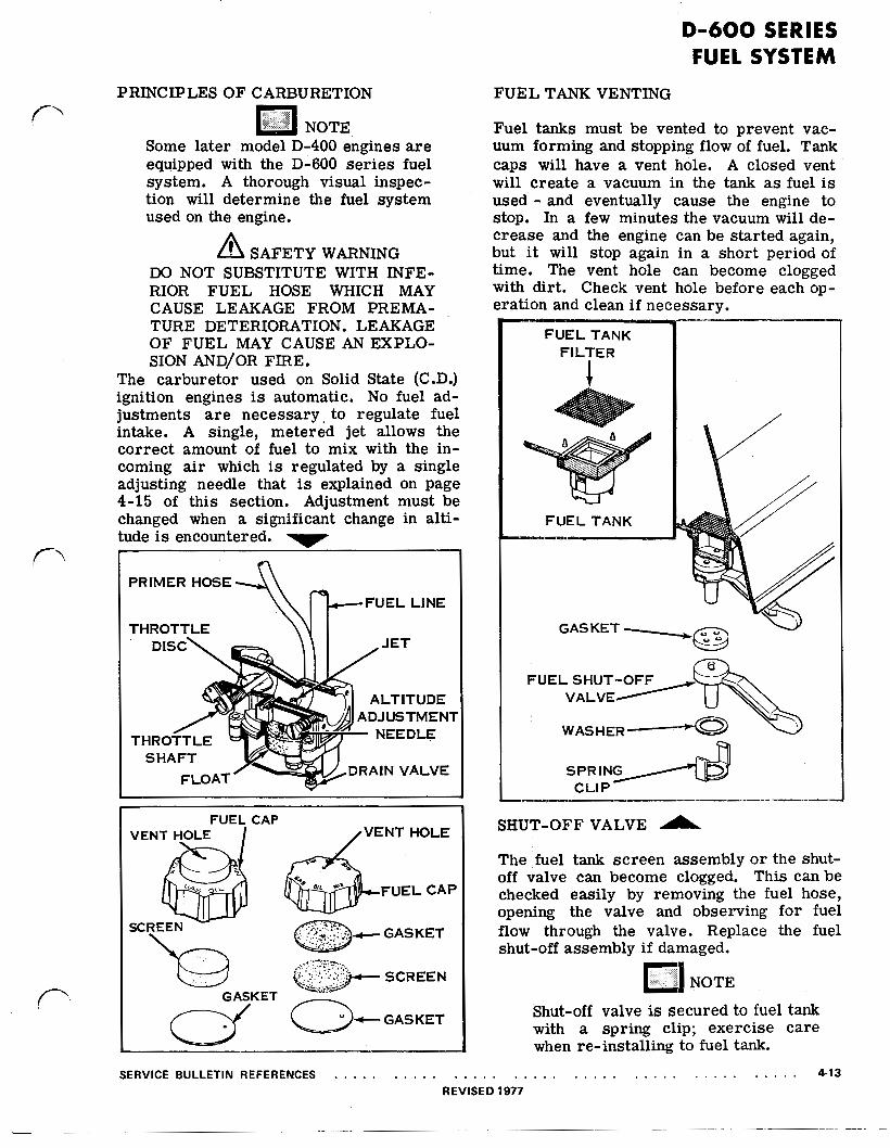
The carburetor used on Solid State (C.D.) ignition engines is automatic. No fuel ad- justments are necessary, to regulate fuel intake. A single, metered jet allows the correct amount of fuel to mix with the in- coming air which is regulated by a single adjusting needle that is explained on page 4-15 of this section. Adjustment must be changed when a significant change in alti- tude is encountered.
.
T
DRAIN VALVE
DJUSTMENT
FUEL CAP
GASKET
FUEL C A P
FUEL TANK VENTING
Fuel tanks must be vented to prevent vac- uum forming and stopping flow of fuel. Tank caps will have a vent hole. A closed vent will create a vacuum in the tank as fuel is used - and eventually cause the engine to stop. In a few minutes the vacuum will de- crease and the engine can be started again, but it will stop again in a short period of time. The vent hole can become clogged with dirt. Check vent hole before each op- eration and clean if necessary.
SERVICE BULLETIN REFERENCES . . . . . . . . . . . .
FUEL TANK F I L T E R
U
FUEL TANK
GASKET
C L I P
SHUT-OFF VALVE
The fuel tank screen assembly or the shut- off valve can become clogged. This can be checked easily by removing the fuel hose, opening the valve and observing for fuel flow through the valve. Replace the fuel shut-off assembly if damaged.
Shut-off valve is secured to fuel tank with a spring clip; exercise care when re-installing to fuel tank.
. . . . . . . . . . . . . . . . . . . . . . . . . . . 4-13 REVISED 1977

D-600 SERIES FUEL SYSTEM
AIR FILTER
AIR VENT PASSAGE
A I R FILTER ASSEMBLY AIR FILTER
-ELEMENT
If engine is flooded, fuel can drain back into filter. As filter becomes saturated, in- coming air picks up more fuel, causing greater flooding. A puckered filter will allow air and dirt to bypass filter. Make certain that filter covers cup area. If oiled properly, filter is very efficient. First wash out with fuel, then apply 10 to 15 drops of oil. Squeeze several times to distribute Reinstall filter in the same position oil. If engine “smokes” for no apparent which it was removed to prevent reason, filter may be saturated with fuel imbedded particles in intake side mix o r may need cleaning. from entering carburetor. Install
air filter case correctly. Hinge on To remove grasp the cover, loosen snap and bottom. If installed upside down the fold cover down. air vent passage will be blocked.
NOTE
Examine the primer system. Instead of into the float bowl chamber which forces lifting fuel up in the carburetor throat as in fuel into the carburetor venturi. the case with some D-400 series engine, the /-
pneumatic primer forces compressed air
4-14 . . . . . . . . . . . . . . . . . . . . . . . . . . . . . . . . . . . . . . . . SERVICE BULLETIN REFERENCES

D-600 SERIES FUEL SYSTEM
1-1/2 TURNS SETTING
\
AIR ADJUSTMENT
The carburetor is completely automatic. There are no adjustments to be made to regulate the amount of fuel entering the car- buretor venturi. There is an atmospheric pressure adjustment that would have to be made if the engine is operating in very high o r very low altitudes.
All D-600 series and modular carburetors require a final adjustment of the altitude needle prior to putting the mower into service.
To adjust, proceed as follows:
1. Pre-set altitude needle 1-1/2 turns from seat.
2. Start engine and allow to run for 3 to 5 minutes to warm up.
3. Place speed control lever in LOW SPEED running position (2400-2600 R.P.M.)
4. Turn altitude needle clockwise until en- gine starts to "hunt," ''surge" or slow down.
5. Slowly turn altitude needle counterclock- wise until engine is running smoothly. Allow engine to run for one or two min-
utes to make sure adjustment is not too lean.
6. Place speed control lever in HIGH SPEED running position (3100-3300 R.P.M.) Observe engine operation. If not running smoothly, turn altitude needle counterclockwise approximately 1/4 turn at a time to obtain proper engine opera- tion.
7. After carburetor adjustment is com- pleted, shut off engine. IMMEDIATELY attempt to restart engine. It should start within 2 pulls on starter handle. Check starting engine at both HIGH and LOW speed settings. If difficult to restart, turn altitude needle 1/8 to 1/4 turn counterclockwise to richen fuel mixture and obtain easy restarting.
DO NOT PRIME A HOT ENGINE.
NOTE
The governor will control the amount of fuel entering the engine. The pur- pose of the atmospheric pressure ad- justing needle is to mix the right amount of fuel with the correct amount of incoming air.
SERVICE BULLETIN REFERENCES . . . . . . . . . . . . . . . . . . . . . . . . . . . . . . . . . . . . . . . . 4-15

D-600 SERIES FUEL SYSTEM
AIR ADJUSTMENT ( Continued )
NOTE
In the closed position no air is en- tering the carburetor vent passage. Therefore, the float bowl pressure has been eliminated and the fuel supply to the carburetor venturi is cut off.
FLOAT AND VALVE
Examine float appearance. Should be glossy because of epoxy sealer. If dull in appear- ance, o r portions of epoxy has chipped away - replace.
NOTE
Do not clean float with any type of solvent or carburetor cleaner. Clean with standard fuel mix.
The float valve consists of a needle and seat assembly, activated by a float in the car- buretor bowl. The steel needle is rubber tipped and the seat brass. This combina- tion eliminates possible sticking and pro- vides a perfect seal. The needle rests on float arm, held in place by a spring clip.
CLOSED SETTING
Operation is automatic. When float bowl is empty, float rests on bottom of bowl, As fuel enters bowl of carburetor, float rises, moving needle valve into seat and shutting off fuel. As engine uses fuel, float drops slightly, allowing more fuel to enter bowl, maintaining a constant fuel level in bowl.
Needle and seat must be replaced as an as- sembly. They are matched to form a per- fect seal.
FLOAT
NEEDLEVALVE
DUMP VALVE ASSEMBLY
GASKET
NOTE: Check dump valve and gasket for distortion o r damage.
4-16 . . . . . . . . . . . . . . . . . . . . . . . . . . . . . . . . . . . . . . . . SERVICE BULLETIN REFERENCES
D-600 SERIES FUEL SYSTEM
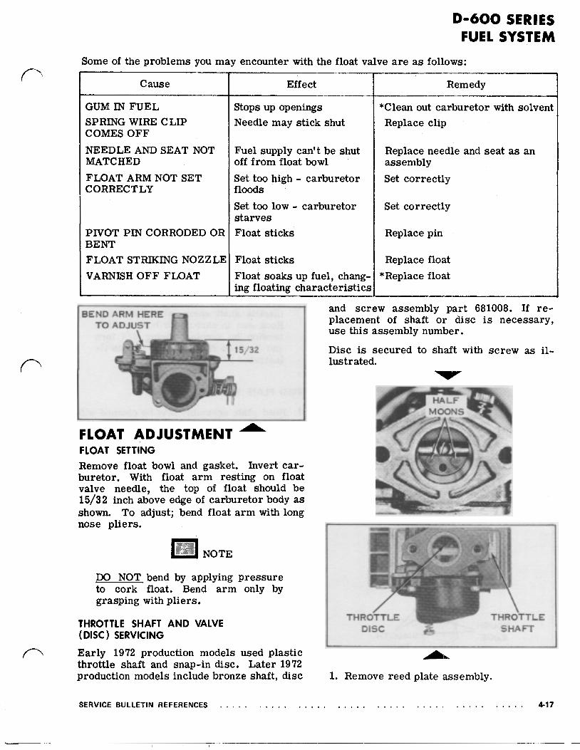
Some of the problems you may encounter with the float valve a re as follows:
Cause
GUM IN FUEL SPRING WIRE C LIP COMES OFF NEEDLE AND SEAT NOT MATCHED FLOAT ARM NOT SET CORRECTLY
PIVOT PIN CORRODED OR BENT FLOAT STRIKING NOZZLE VARNISH OFF FLOAT
Effect
Stops up openings Needle may stick shut
Fuel supply can't be shut off from float bowl Set too high - carburetor floods Set too low - carburetor starves Float sticks
Float sticks Float soaks up fuel, chang- ing floating characteristics
BEND ARM HERE TO ADJUST
2
FLOAT ADJUSTMENT FLOAT SETTING Remove float bowl and gasket. Invert car- buretor. With float arm resting on float valve needle, the top of float should be 15/32 inch above edge of carburetor body as shown. To adjust; bend float arm with long nose pliers.
DO NOT bend by applying pressure to cork float. Bend arm only by grasping with pliers.
THROTTLE SHAFT AND VALVE (DISC) SERVICING Early 1972 production models used plastic throttle shaft and snap-in disc. Later 1972 production models include bronze shaft, disc
*Clean out carburetor with solvent Replace clip
Replace needle and seat as an assembly Set correctly
Set correctly
Replace pin
Replace float *Replace float
and screw assembly part 681008. If re- placement of shaft or disc is necessary, use this assembly number.
Disc is secured to shaft with screw as il- lustrated.
1. Remove reed plate assembly.
SERVICE BULLETIN REFERENCES . . . . . . . . . . . . . . . . . . . . . . . . . . . . . . . . . . . . . . . . 4-17
D-600 SERIES FUEL SYSTEM
MACHINED SURFACE
ROUGH EDGE
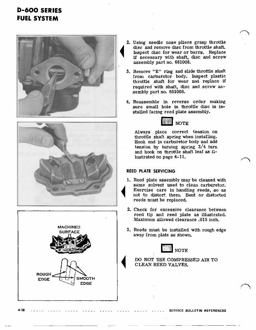
2. Using needle nose pliers grasp throttle disc and remove disc from throttle shaft. Inspect disc for wear or burrs. Replace if necessary with shaft, disc and screw assembly part no. 681008.
3. Remove '"E" ring and slide throttle shaft from carburetor body. Inspect plastic throttle shaft for wear and replace if required with shaft, disc and screw as- sembly part no. 681008.
4. Reassemble in reverse order making sure small hole in throttle disc is in- stalled facing reed plate assembly.
NOTE
Always place correct tension on throttle shaft spring when installing. Hook end in carburetor body and add tension by turning spring 3/4 turn and hook on throttle shaft leaf as il- lustrated on page 4- 11.
REED PLATE SERVICING
1. Reed plate assembly may be cleaned with same solvent used to clean carburetor. Exercise care in handling reeds, so as not to distort them. Bent or distorted reeds must be replaced.
2. Check for excessive clearance between reed tip and reed plate as illustrated. Maximum allowed clearance .015 inch.
3. Reeds must be installed with rough edge away from plate as shown.
NOTE
DO NOT USE COMPRESSED AIR TO CLEAN REED VALVES.
4-18 . . . . . . . . . . . . . . . . . . . . . . . . . . . . . . . . . . . . . . SERVICE BULLETIN REFERENCES

MODULAR CARBURETOR
MODULAR CARBURETOR C O M P O N E N T S
The new modular carburetor was introduced in the 1975 D-600 ser ies engines and later production D-400 ser ies engines. This new carburetor is constructed of a special injection molded plastic material. The body and air filter chamber is a one-piece plastic assembly which "plugs" into the reed plate and is secured by a single screw. An O- ring installed between the carburetor and reed plate insures positive sealing. The float and fuel valve is also a one-piece as- sembly. This assembly rests on a spring located in the plastic float chamber. The spring provides vertical tension against the float forcing the fuel valve into the fuel in- let seat when the float chamber is full of fuel. As fuel enters a single metered jet it is mixed with incoming air to form the cor- rect combustible mixture. The amount of fuel flow through the metering jet is regu- lated by the altitude needle. Adjustment procedure is same as earlier D-600 series carburetors. Refer to page 4-15 for adjust- ment procedure.
CARBURETOR BODY
"0" RING
FLOAT AND VE ASSEMBLY
PLATE ASSEMBLY
FLOAT CHAMBER
The governor will control the amount of fuel entering the engine. The pur- pose of the atmospheric pressure adjusting needle is to mix the right amount of fuel with the correct amount of incoming air.
SERVICE BULLETIN REFERENCES . . . . . . . . . . . . . . . . . . . . . . . . . . . . . . . . . . . . . . . 4-19
.

MODULAR CARBURETOR
O- R I N G
An O-ring seals between the outer surface of the carburetor barrel and the inside di- ameter of the reed plate opening. The cor- rect procedure to install the carburetor is to lubricate the O-ring in groove of the reed plate and "plug" in the carburetor.
When installing or removing carbu- retor from engine, the governor rod must be removed from the throttle arm.
CLEANING CARBURETOR altitude needle for damage, Check spring for damage - DO NOT BEND SPRING.
The carburetor assembly is injection molded Check gasket for cracks or wear. Always plastic. DO NOT clean using a standard use new gasket during reassembly. carburetor cleaner. Disassemble carbure-
grease solvent, dry and clean parts with compressed air - DO NOT dry using a If any part appears worn o r damaged, cloth, lint may block passages impeding replace it. To ensure proper float proper carburetor operation. action the float must be correctly in-
tor components, wash and clean using a good NOTE
stalled in float chamber (not binding). After cleaning, inspect all parts. Check After assembling float chamber to float and fuel valves for cracks or damage. carburetor body shake in a vertical Check throttle shaft, valve and spring for motion and listen for float move- smooth operation. Check float chamber for ment. If no sound (movement) is cracks or damage. Check dump valve and heard remove float chamber and re- gasket for distortion or damage. Check install correctly.
ALTITUDE CARBURETOR BODY NEEDLE
I
DUMP VALVE
FLOAT CHAMBER I
4-20 . . . . . . . . . . . . . . . . . . . . . . . . . . . . . . . . . . . . . . . . SERVICE BULLETIN REFERENCES
MODULAR
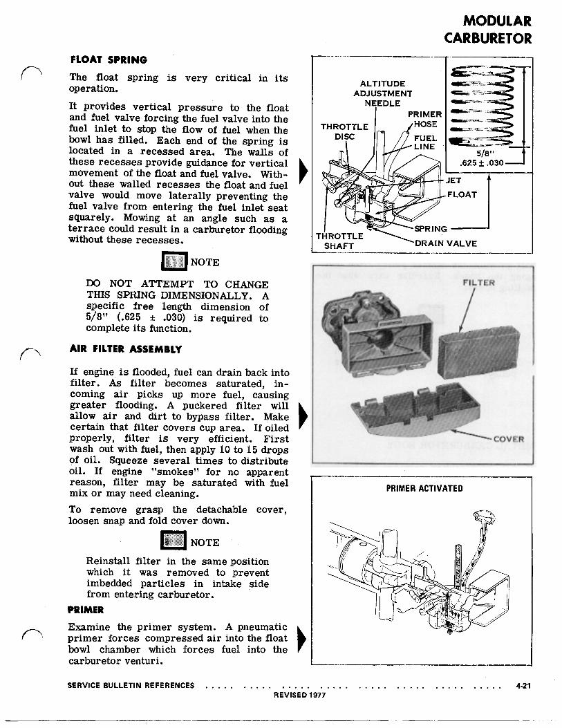
FLOAT SPRING The float spring is very critical in its operation.
It provides vertical pressure to the float and fuel valve forcing the fuel valve into the fuel inlet to stop the flow of fuel when the bowl has filled. Each end of the spring is located in a recessed area. The walls of these recesses provide guidance for vertical movement of the float and fuel valve. With- out these walled recesses the float and fuel valve would move laterally preventing the fuel valve from entering the fuel inlet seat squarely. Mowing at an angle such as a terrace could result in a carburetor flooding without these recesses.
DO NOT ATTEMPT TO CHANGE THIS SPRING DIMENSIONALLY. A specific free length dimension of 5/8" (.625 ± .030) is required to complete its function.
AIR FILTER ASSEMBLY
If engine is flooded, fuel can drain back into filter. As filter becomes saturated, in- coming air picks up more fuel, causing greater flooding. A puckered filter will allow air and dirt to bypass filter. Make certain that filter covers cup area. If oiled properly, filter is very efficient. First wash out with fuel, then apply 10 to 15 drops of oil. Squeeze several times to distribute oil. If engine "smokes" for no apparent reason, filter may be saturated with fuel mix or may need cleaning. To remove grasp the detachable cover, loosen snap and fold cover down.
Reinstall filter in the same position which it was removed to prevent imbedded particles in intake side from entering carburetor.
PRIMER Examine the primer system. A pneumatic primer forces compressed air into the float bowl chamber which forces fuel into the carburetor venturi.
SERVICE BULLETIN REFERENCES . . . . . . . . . . . .
FILTER
~,
PRIMER ACTIVATED
. . . . . . . . . . . . . . . . . . . . . . . . . . . 4-21 REVISED 1977

MODULAR CARBURETOR
FUEL AND PRIMER HOSE R O U T I N G
DO NOT SUBSTITUTE WITH INFE- RIOR FUEL HOSE WHICH MAY CAUSE LEAKAGE FROM PREMA- TURE DETERIORATION. LEAKAGE OF FUEL MAY CAUSE AN EXPLO- SION AND/OR FIRE.
PLASTIC CARBURETOR BODY
Proper hose routing requires the primer hose to be twisted counterclockwise approx- imately 1/2 turn around the fuel line. This will prevent the starter pulley from dam- aging the hoses. Exercise care when in- stalling hoses.
Do not pull hoses taut in either di- rection. Leave sufficient slack in hoses to prevent contact with starter pulley.
METALCARBURETORBODY
Proper hose routing requires the hoses to be parallel with each other as shown. If twisted, i t is possible for hoses to be dam- aged by starter pulley. Exercise care when installing hoses.
1 COUNT
AROUN
4-22 . . . . . . . . . . . . . . . . . . . . . . . . . . . . . . . . . . . . . . . . SERVICE BULLETIN REFERENCES REVISED 1977
D-600 SERIES FUEL SYSTEM TROUBLE SHOOTING
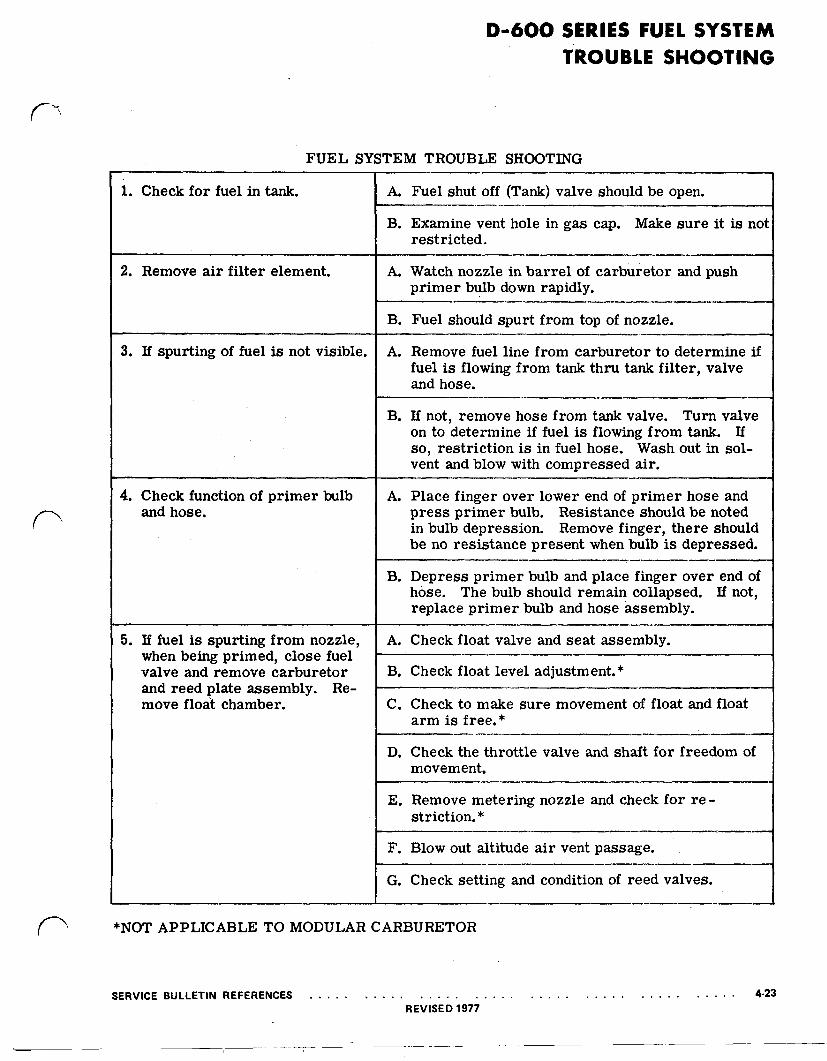
FUEL SYSTEM TROUBLE SHOOTING
1. Check for fuel in tank.
2. Remove air filter element.
3. If spurting of fuel is not visible.
4. Check function of primer bulb and hose.
5. If fuel is spurting from nozzle, when being primed, close fuel valve and remove carburetor and reed plate assembly. Re- move float chamber.
A. Fuel shut off (Tank) valve should be open.
B. Examine vent hole in gas cap. Make sure it is not restricted.
A. Watch nozzle in barrel of carburetor and push primer bulb down rapidly.
B. Fuel should spurt from top of nozzle.
A. Remove fuel line from carburetor to determine if fuel is flowing from tank thru tank filter, valve and hose.
B. If not, remove hose from tank valve. Turn valve on to determine if fuel is flowing from tank. If so, restriction is in fuel hose. Wash out in sol- vent and blow with compressed air.
A. Place finger over lower end of primer hose and press primer bulb. Resistance should be noted in bulb depression. Remove finger, there should be no resistance present when bulb is depressed.
B. Depress primer bulb and place finger over end of hose. The bulb should remain collapsed. If not, replace primer bulb and hose assembly.
A. Check float valve and seat assembly.
B. Check float level adjustment.*
C. Check to make sure movement of float and float arm is free.*
D. Check the throttle valve and shaft for freedom of movement.
E. Remove metering nozzle and check for re- striction. *
F. Blow out altitude air vent passage.
G. Check setting and condition of reed valves.
*NOT APPLICABLE TO MODULAR CARBURETOR
SERVICE BULLETIN REFERENCES . . . . . . . . . . . . . . . . . . . . . . . . . . . . . . . . . . . . . . , 4-23 REVISED 1977

MODULAR CARBURETOR - UTILITY MODELS MODULAR CARBURETOR COMPONENTS
The new modular carburetor was introduced in the 1979 D-410 series engines on all utility models. This new carburetor is constructed of a special in- jection molded plastic material. The body and air filter chamber is a one-piece plastic assembly which “plugs” into the reed plate and is secured by a single screw. An O-ring installed between the car- buretor and reed plate insures positive sealing. The modular carburetor has been redesigned featuring a new float chamber, gasket, float and carburetor body. A hinged type float of special cork material is sealed with an epoxy. During inspection, if . the float appears dull or dark in appearance it should be replaced. The float in this new modular carbu- retor is positioned differently than previous modular carburetors with the float upside down, and a float level adjustment requirement of 11/16 inches from carburetor body to top of float. As fuel enters a single metered jet it is mixed with incoming air to form the correct combustible mixture. The amount of fuel flow through the metering jet is regulated by the altitude needle.
NOTE
The governor will control the amount of fuel entering the engine. The purpose of the atmospheric pressure adjusting needle is to mix the right amount of fuel with the correct amount of incoming air.
NOTE
This new modular carburetor is also a Service replacement component for all pre- vious D-Series modular carburetors. A Quick visual inspection will show you which modular carburetor is on the engine.
CARBURETOR BODY FLOAT
CHAMBER
4-24 . . . . . . . . . . . . . . . . . . . . . . . .
AIR FILTER ASSEMBLY
If engine is flooded, fuel can drain back into filter. As filter becomes saturated, incoming air picks up more fuel, causing greater flooding. A puckered filter will allow air and dirt to bypass filter. Make certain that filter covers cup area. If oiled properly, filter is very efficient. First wash out with fuel, then apply 10 to 15 drops of oil. Squeeze several times to distribute oil. If engine “smokes” for no apparent reason, filter may be saturated with fuel mix or may need cleaning.
To remove grasp the detachable cover, loosen snap and fold cover down.
a
NOTE
Reinstall filter in the same position from which it was removed to prevent imbedded particles in intake side from entering car- buretor.
CARBURETOR REMOVAL
1. The modular carburetor is attached to the reed plate assembly by a single screw.
. . . . . . . . . . SERVICE BULLETIN REFERENCES

MODULAR CARBURETOR - UTILITY MODELS
During reassembly apply Lawn-Boy nut and screw lock part no. 682301 to threads of mounting screw.
2. Pull carburetor from reed plate assembly. Do not bend or damage the governor rod and/or throttle arm of the carburetor.
3. Check O-ring in reed plate assembly for damage. We recommend replacing O-ring every mowing season and during all tune-up operations.
O-RING
An O-ring seals between the outer surface of the carburetor barrel and the inside diameter of the reed plate opening. The correct procedure to install the carburetor is to lubricate the O-ring in groove of the reed plate and “plug” in the carburetor.
CARBURETOR
SERVICE BULLETIN REFERENCES . . . . . . . . . .
CLEANING CARBURETOR
The carburetor assembly is injection molded plastic.
Disassemble carburetor components, wash and clean using a good grease solvent, dry and clean parts with compressed air - DO NOT dry using a cloth, lint may block passages impeding proper carburetor operation.
After cleaning, inspect all parts. Check float and fuel valves for cracks or damage. Check throttle shaft, valve and spring for smooth operation. Check float chamber for cracks or damage. Check altitude needle and O-ring for damage. Check air vent passage which allows air to flow into the float chamber. If this passage should become restricted with dirt and/or debris the engine will not run correctly or stop running and flooding of carburetor will occur. Check gasket for cracks or wear. Always use new gasket during reassembly.
DO NOT clean using a standard carburetor cleaner.
AIR VENT PASSAGE I
NOTE
If any part appears worn or damaged, re- place it. To ensure proper float action the float must be correctly installed in float chamber (not’ binding). Use needle nose pliers to secure hinge on float arm to pin.
. . . , . . . , . . . . . . . . . . . . . . . . 4-25

MODULAR CARBURETOR - UTILITY MODELS FLOAT AND VALVE ASSEMBLY
The float valve consists of a needle and seat as- sembly, activated by a float in the carburetor bowl. The steel needle is rubber tipped and the seat brass. This combination eliminates possible sticking and provides a perfect seal. The needle rests on float arm, held in place by a spring clip.
Operation is automatic. When float bowl is empty, float rests on bottom of bowl. As fuel enters bowl of carburetor, float rises, moving needle valve into seat and shutting off fuel. As engine uses fuel, float drops slightly, allowing more fuel to enter bowl, maintaining a constant fuel level in bowl.
Needle, seat and spring clip must be replaced as an assembly. They are matched to form a perfect seal.
Remove float bowl and examine float appearance. Float should be glossy because of epoxy sealer. If dull in appearance, or portions of epoxy have chipped away - replace float.
NOTE
Do not clean float with any type of sol- vent or carburetor cleaner. Replace it.
Some of the problems you may encounter with the float valve are as follows:
VARNISH
SPRING WIRE CLIP COMES OFF
NEEDLE AND SEAT NOT MATCHED
FLOAT ARM NOT SET CORRECTLY
PIVOT PIN CORRODED OR BENT
FLOAT STRIKING NOZZLE
VARNISH OFF FLOAT
LOOSE FLOAT HINGE CLIP ON PIVOT PIN
Effect
Stops up openings
Needle may stick shut
Fuel supply can’t be shut off from float bowl
Set too high - carburetor floods - Engine runs rich
Set too low - carburetor starves - Engine runs lean
Float sticks
Float sticks
Float soaks up fuel, chang- ing floating characteristics
Engine 4 cycles excessively when bumped or jarred
Remedy
Clean out carburetor with solvent
Replace clip
Replace needle and seat as an assembly
Set correctly
Set correctly
Replace pin
Replace float
Replace float
Crimp float hinge clip on pivot pin for tighter fit
4-26 . . . . . . . . . . . . . . . . . . . . . . . . . . . . . . . . . . SERVICE BULLETIN REFERENCES

MODULAR CARBURETOR = UTILITY MODELS FLOAT ADJUSTMENT
Float Setting
Remove float bowl and gasket. Invert carburetor. With float arm resting on float valve needle, the top of float should be 11/16 inch above edge of carburetor body as shown. Obtain measurements at two points at right angles to each other.
If adjustment is required; using needle nose pliers bend float arm as shown. DO NOT bend float arm by applying pressure to float, this will damage rubber tip on inlet needle.
Check hinge on float arm to be sure it is secured to pin. Use needle nose pliers and tighten hinge. The hinge should be clamped tight enough so that the pin will swivel in the carburetor instead of the arm turning on the pin.
NOTE
Tightening hinge to pivot pin will prevent inlet needle from not seating correctly when mower crosses uneven terrain. This condition is called “fluttering.”
Check pin clip on float arm by rotating carburetor sideways. If clip falls off float arm -- replace it.
SERVICE BULLETIN REFERENCES . . . . . . . . . .
MEASURE AT RIGHT ANGLES
FLOAT VALVE AND SEAT ASSEMBLY
NOTE
The float valve and seat must be replaced as an assembly. They are matched to form a perfect seal.
1. Remove hinge pin and remove float and valve. Remove spring clip securing valve to float arm.
. . . . . . . . . . . . . . . . . . . . . . . . 4-27
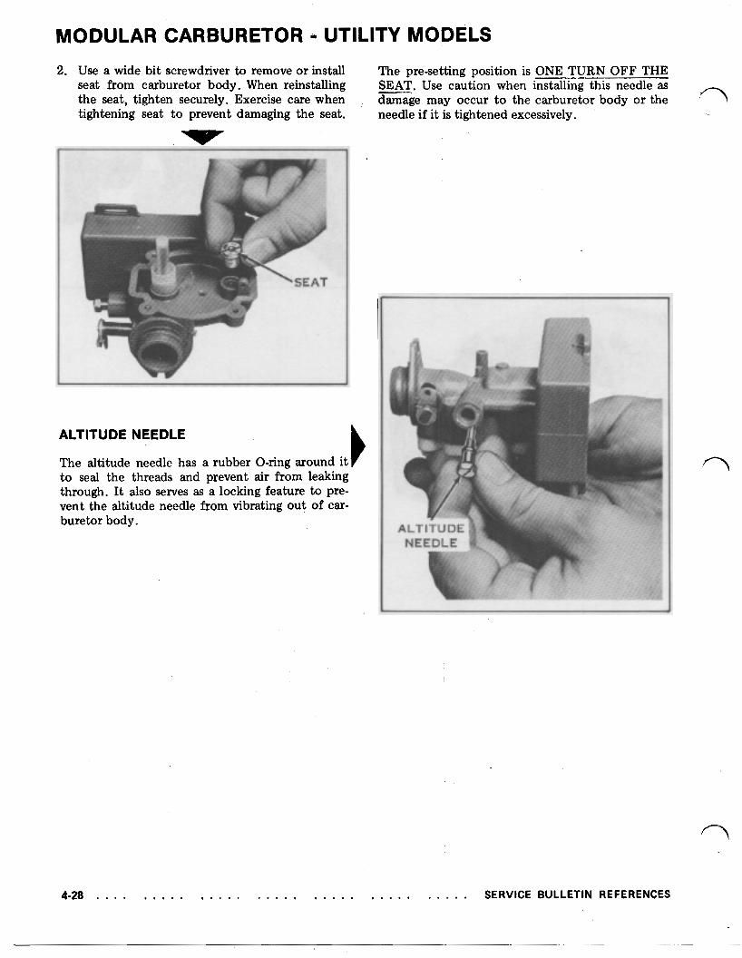
MODULAR CARBURETOR - UTILITY MODELS 2. Use a wide bit screwdriver to remove or install The pre-setting position is ONE TURN OFF THE
seat from carburetor body. When reinstalling SEAT. Use caution when installing this needle as the seat, tighten securely. Exercise care when damage may occur to the carburetor body or the tightening seat to prevent damaging the seat. needle if it is tightened excessively,
I I
ALTITUDE NEEDLE
The altitude needle has a rubber O-ring around it to seal the threads and prevent air from leaking through. It also serves as a locking feature to pre- vent the altitude needle from vibrating out of car- buretor body.
4-28 . . . . . . . . . . . . . . . . . . . . . . . . . . . . . . . . . . SERVICE BULLETIN REFERENCES