lathe - spindle - replacement...lathe - spindle - replacement lathe - spindle - replacement -...
TRANSCRIPT
Haas Technical DocumentationEffective Date:
Lathe - Spindle - Replacement
Lathe - Spindle - Replacement - Removal
January, 1997 - June, 2011
NOTE: Ensure the turret and tailstock, if equipped, are in the home position.
Power off the machine before performing the following procedure.
Mini Lathe (ML): Remove the door, the coolant collector from the spindle, and the left front and left side en-
closure panels. Disconnect the air/oil lube lines that supply the spindle and the air closer.
1. Remove the chuck or collet nose from the lathe and the necessary covers to gain access to the spindle
assembly. ML: Remove the workholding device, air closer, adapter, and draw tube (by screwing it out).
Toolroom Lathe (TL): Remove sheetmetal panel from the left side of the machine casting. This will gain ac-
cess to the spindle motor and belt.
TL: Remove the belt from the spindle pulley. To do this loosen the three bolts on the motor mounting plate
in the belt so it can be removed from the pulley.
ML: Remove the belt from the drive pulley. Attach a hydraulic puller to the drive sprocket.
TL and ML: Remove the SHCS that secure the spindle front cap to the spindle housing and remove the
spindle cartridge from the motor end of the spindle housing.
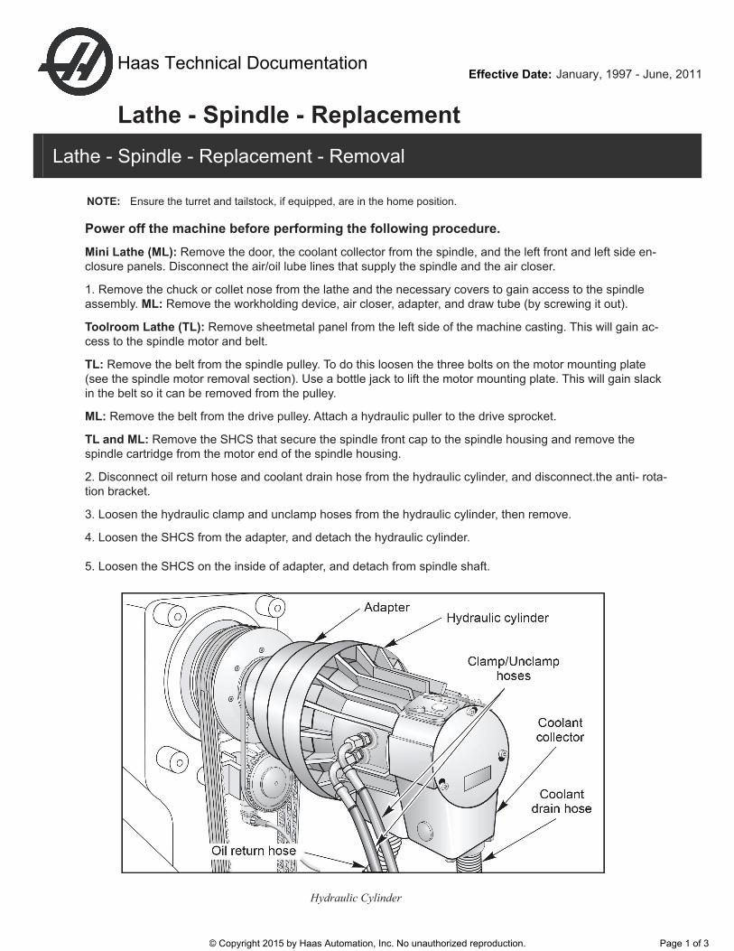
2. Disconnect oil return hose and coolant drain hose from the hydraulic cylinder, and disconnect.the anti- rota-
tion bracket.
3. Loosen the hydraulic clamp and unclamp hoses from the hydraulic cylinder, then remove.
4. Loosen the SHCS from the adapter, and detach the hydraulic cylinder.
5. Loosen the SHCS on the inside of adapter, and detach from spindle shaft.
Hydraulic Cylinder
© Copyright 2015 by Haas Automation, Inc. No unauthorized reproduction. Page 1 of 3
Lathe - Spindle - Replacement - Installation
6. Loosen the four SHCS holding the spindle motor. Slide the motor up by squeezing the belts. Tighten
the SHCS and remove the drive belts from the spindle assembly.
7. Unplug the encoder. Unscrew the encoder bracket, remove the encoder, then remove the belt.
SL-10 - You do not have to remove the encoder.
8. Loosen the six SHCS and remove the spindle drive pulley.
10. Unscrew SHCS holding the spindle retaining ring (located at spindle nose) and remove. Also remove o-
ring.
11. Remove the spindle carefully through the machine front.
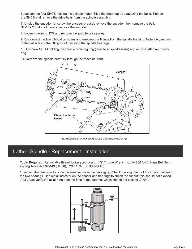
SL-10 Hydraulic Cylinder (Coolant Collector not Shown)
Tools Required: Removable thread locking compound, 1/2” Torque Wrench (Up to 250 ft-lb), Haas Belt Ten-
sioning Tool P/N 93-8143 (SL 20), P/N T1537 (SL 30 and 40)
1. Inspect the new spindle once it is removed from the packaging. Check the alignment of the spacer between
.003”. Also verify the axial runout on the face of the bearing, which should not exceed .0004”.
© Copyright 2015 by Haas Automation, Inc. No unauthorized reproduction. Page 2 of 3
2. Install spindle into housing. Check location of oil holes for proper alignment.
3. Place the retainer ring on the spindle with the O-ring toward the spindle. Ensure that the drain holes are at
the bottom of the retainer ring and that the O-ring remains in place.
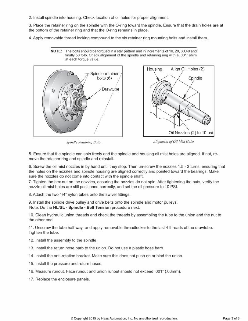
4. Apply removable thread locking compound to the six retainer ring mounting bolts and install them.
NOTE: The bolts should be torqued in a star pattern and in increments of 10, 20, 30,40 and
at each torque value.
seloH tsiM liO fo tnemngilA stloB gniniateR eldnipS
5. Ensure that the spindle can spin freely and the spindle and housing oil mist holes are aligned. If not, re-
move the retainer ring and spindle and reinstall.
6. Screw the oil mist nozzles in by hand until they stop. Then un-screw the nozzles 1.5 - 2 turns, ensuring that
the holes on the nozzles and spindle housing are aligned correctly and pointed toward the bearings. Make
sure the nozzles do not come into contact with the spindle shaft.
7. Tighten the hex nut on the nozzles, ensuring the nozzles do not spin. After tightening the nuts, verify the
nozzle oil mist holes are still positioned correctly, and set the oil pressure to 10 PSI.
9. Install the spindle drive pulley and drive belts onto the spindle and motor pulleys.
10. Clean hydraulic union threads and check the threads by assembling the tube to the union and the nut to
the other end.
11. Unscrew the tube half way and apply removable threadlocker to the last 4 threads of the drawtube.
Tighten the tube.
12. Install the assembly to the spindle
13. Install the return hose barb to the union. Do not use a plastic hose barb.
14. Install the anti-rotation bracket. Make sure this does not push on or bind the union.
15. Install the pressure and return hoses.
16. Measure runout. Face runout and union runout should not exceed .001” (.03mm).
17. Replace the enclosure panels.
Note: Do the HL/SL - Spindle - Belt Tension procedure next.
© Copyright 2015 by Haas Automation, Inc. No unauthorized reproduction. Page 3 of 3