laser system for single event effects testing and ... · laser system for single event effects...
TRANSCRIPT
Laser System for Single Event Effects Laser System for Single Event Effects Testing and Radiation Sensitivity Testing and Radiation Sensitivity
Mapping of ICsMapping of ICs
Behcet Alpat Behcet Alpat INFN INFN PerugiaPerugia

Corso Qual. Spaziale, Pg, 14-15th Sept. 2004 2Behcet Alpat, INFN-Pg
Critical Parameters for Critical Parameters for Mission Definition for Mission Definition for Radiation PredictionsRadiation Predictions
When and how long the mission will fly When and how long the mission will fly Where the mission will fly Where the mission will fly When the systems are deployed When the systems are deployed What systems must operate during worst case What systems must operate during worst case environment conditions environment conditions What systems are critical to mission success What systems are critical to mission success Amount of shielding surrounding devicesAmount of shielding surrounding devices

Corso Qual. Spaziale, Pg, 14-15th Sept. 2004 3Behcet Alpat, INFN-Pg
SEE Rate CalculationsSEE Rate Calculations
Involves 3 different quantities;Involves 3 different quantities;The cross section of the device, often determined The cross section of the device, often determined empirically;empirically;The distribution of particles expected in the space The distribution of particles expected in the space environment, which depends on assumptions about environment, which depends on assumptions about solar flare activity, radiation belt activity, andsolar flare activity, radiation belt activity, andshielding; shielding; The critical charge, sensitive area and sensitive The critical charge, sensitive area and sensitive volume associated with the SEE phenomenon of volume associated with the SEE phenomenon of interest.interest.

Corso Qual. Spaziale, Pg, 14-15th Sept. 2004 4Behcet Alpat, INFN-Pg
SEE Ground Testing SEE Ground Testing
FacilitiesFacilitiesHeavyHeavy--IonIonProtonProtonCaliforniumCalifornium--252 source 252 source Pulsed laserPulsed laser

Corso Qual. Spaziale, Pg, 14-15th Sept. 2004 5Behcet Alpat, INFN-Pg
Understanding of Laser Understanding of Laser TechniqueTechnique
Radial charge (carrier) densityRadial charge (carrier) densityPulse width effectsPulse width effectsSurface reflectionsSurface reflectionsNonNon--linear absorption (TPA) problem linear absorption (TPA) problem (Choice of optical wavelength)(Choice of optical wavelength)
Free carrier recombination and Funnelling Free carrier recombination and Funnelling problemsproblemsComparability of ion and laser charge Comparability of ion and laser charge collectioncollection

Corso Qual. Spaziale, Pg, 14-15th Sept. 2004 6Behcet Alpat, INFN-Pg
Pulse WidthPulse Width
Relative SEL threshold laser energy vs. pulse duration. Normalized dependence is in smooth rising (E0 corresponds to minimum pulse duration which is 10 psin this case). For our case (15 ns) this factor is about 2.5 (E0).Reference: IEEE Trans. Nuc. Sc. V44, N6, Dec 1997 (2034)

Corso Qual. Spaziale, Pg, 14-15th Sept. 2004 7Behcet Alpat, INFN-Pg
Surface ReflectionsSurface Reflections
Need to know accurately the amount of light that enters the deviNeed to know accurately the amount of light that enters the device. ce. The amount of light entering the device will depend on the naturThe amount of light entering the device will depend on the nature of the e of the device surface and on the presence of the device surface and on the presence of the passivationpassivation layers used for the layers used for the protection of the device surfaceprotection of the device surface
Θ=∆
−=
==
∆+
⋅
−
=
cos4
by d, kness,layer thic on the dependsion transmiss theand function)(Airy 1
4interface. Si:SiO to and and interface SiO:air therefer to and e.reflectanc and ttancely transmirespective are and
Also layer.n passivatio at theincident intensity theis and substratesilicon the toed transmittintensity theis where
)2/(sin11
1
2
222211
2121
0
22
2
0
λπndRRF
trtrrrRttT
IIFR
TII
t
r

Corso Qual. Spaziale, Pg, 14-15th Sept. 2004 8Behcet Alpat, INFN-Pg
Surface Reflections Surface Reflections (cont’d)(cont’d)
Calculating the expected surface Calculating the expected surface reflections from the VA gives reflections from the VA gives
For n(SiOFor n(SiO22)=1.5 and n(Si)=3.65 )=1.5 and n(Si)=3.65 at at ΘΘ=0 =0
The relative reflection has been The relative reflection has been measured and calculated measured and calculated analytically.analytically.
Reflection measurement: we Reflection measurement: we measured the reflected photons at the measured the reflected photons at the same solid angle first from a mirror same solid angle first from a mirror and than from VA (obtaining relative and than from VA (obtaining relative reflection VA/mirror) . The average reflection VA/mirror) . The average relative reflection is about 30%. (over relative reflection is about 30%. (over 100 incident photons 30 are reflected)100 incident photons 30 are reflected)

Corso Qual. Spaziale, Pg, 14-15th Sept. 2004 9Behcet Alpat, INFN-Pg
TPA problemTPA problem
Two Photon Absorption: at high laser intensity it is possible thTwo Photon Absorption: at high laser intensity it is possible that the at the absorption of two photons produces only one holeabsorption of two photons produces only one hole--electron pair.electron pair.It’s the most probable non linear effect in light absorption anIt’s the most probable non linear effect in light absorption and is d is ruled by: ruled by:
β=β=two photon absorption coefficient, two photon absorption coefficient, α=α=linear absorption coefficienlinear absorption coefficienttNote Note thatthat thisthis problemproblem arisesarises withwith high SEE LET high SEE LET thresholdthreshold (30(30--50 50 MeVMeV/mg/cm/mg/cm22))Use of 0.8 Use of 0.8 µµm wavelength reduces this nonlinear contribution by a m wavelength reduces this nonlinear contribution by a factor 100 factor 100 wrtwrt the the useuse of a of a wavelengthwavelength nearnear bandgapbandgap (1.13 (1.13 µµm)m)
)e()αIβ(
eII(z)zα
zα
⋅−
⋅−
−⋅⋅
+⋅=
11 00

Corso Qual. Spaziale, Pg, 14-15th Sept. 2004 10Behcet Alpat, INFN-Pg
Carrier Lifetime & Carrier Lifetime & FunnellingFunnelling
Funnelling: when a track charge density is Funnelling: when a track charge density is higher than the doping density, the junction higher than the doping density, the junction electric field is distorted; this can determine electric field is distorted; this can determine extra charge collection.extra charge collection.Carrier lifetime: holeCarrier lifetime: hole--electron recombination electron recombination rate is charge density dependent; high rate is charge density dependent; high recombination rate lowers the charge recombination rate lowers the charge collection.collection.Both effects depends on charge density, that Both effects depends on charge density, that is different between laser and ion. That’s why is different between laser and ion. That’s why we can’t completely substitute the ionwe can’t completely substitute the ion--beam beam test with the laser method.test with the laser method.

Corso Qual. Spaziale, Pg, 14-15th Sept. 2004 11Behcet Alpat, INFN-Pg
Laser System Test CapabilitiesLaser System Test Capabilities
)1010(101)cos(
24 ×⋅⋅⋅
⋅=⋅= π
θσ RNbSELaSampledAre
IntFlxNbSEL
••SEL Sensitivity SEL Sensitivity MappingMapping
••Cross Cross SectionSection vsvs LETLETmeasuringmeasuring
We generate an array of We generate an array of pulsed pulsed laser ionization trackslaser ionization tracks ((EnergyEnergy) over ) over
a scanning a scanning matrixmatrix (i.e. 22x20) to (i.e. 22x20) to simulate a SEE Ion beam test (100 simulate a SEE Ion beam test (100 pulses for each position pulses for each position -- IntFlxIntFlx) )
WeWe countcount SEL SEL eventevent numbernumber((NbSELNbSEL) ) forfor eacheach position and position and forfor a a
decreasingdecreasing laser laser opticaloptical power:power:
SiSi dEnergyLET
⋅=
ρ
The mapping is generated by scanning the DUT surface along a number of rows and stepping the DUT in the normal direction at the end of each scan (the same step of Cs vs LET procedure).
The correlation between the Laser beam energy and the DUT response joint to accurate spatial information defines the sensitivity map of the different functional blocks of the chip the alignment technique is very important.

Corso Qual. Spaziale, Pg, 14-15th Sept. 2004 12Behcet Alpat, INFN-Pg
System Setup for SEE Studies (Details and Specs)
• Pulsed Laser Diode • 20W (@peak, 10kHz), λ=913±10nm
• 15ns pulse width• Operating voltage range
9÷14.5V• Repetition freq. up to 10kHz

Corso Qual. Spaziale, Pg, 14-15th Sept. 2004 13Behcet Alpat, INFN-Pg
System Setup for SEE Studies (Details and Specs)
• Astigmatism corrector to have a quasi-circular laser spot
• PC based IR Imaging System
Corso Qual. Spaziale, Pg, 14-15th Sept. 2004 14Behcet Alpat, INFN-Pg
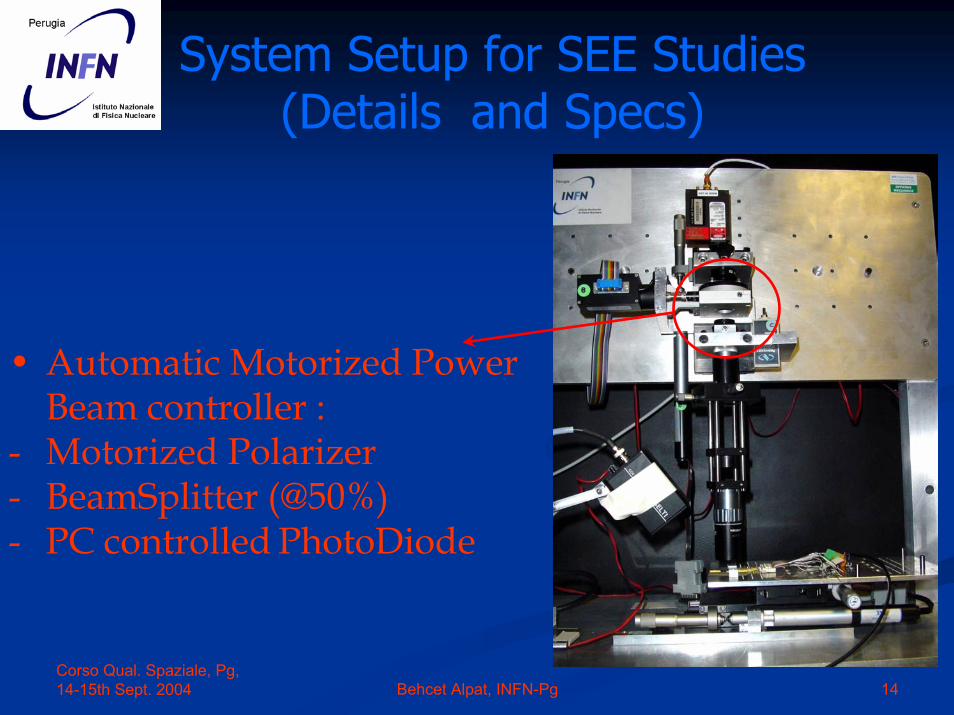
System Setup for SEE Studies (Details and Specs)
• Automatic Motorized Power Beam controller :
- Motorized Polarizer- BeamSplitter (@50%)- PC controlled PhotoDiode

Corso Qual. Spaziale, Pg, 14-15th Sept. 2004 15Behcet Alpat, INFN-Pg
System Setup for SEE Studies (Details and Specs)
Focusing Optical Setup
Spot size (FHWM) of about 10 µm
Motorized (1 µm repeatability) Z-axe

Corso Qual. Spaziale, Pg, 14-15th Sept. 2004 16Behcet Alpat, INFN-Pg
System Setup for SEE Studies (Details and Specs)
• PC controlled XY stagewith a
1 µm bi-directional accuracy
Corso Qual. Spaziale, Pg, 14-15th Sept. 2004 17Behcet Alpat, INFN-Pg
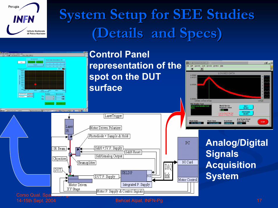
System Setup for SEE Studies System Setup for SEE Studies (Details and Specs)(Details and Specs)
Control Panel representation of the spot on the DUT surface
Analog/Digital Signals Acquisition System

Corso Qual. Spaziale, Pg, 14-15th Sept. 2004 18Behcet Alpat, INFN-Pg
Analog/Digital Signals Analog/Digital Signals Acquisition System (1/2): SELDPAcquisition System (1/2): SELDP
Power IN fromSupply
Power OUT to DUTCounter
Delay presetting
SELDP (Single Event Latchup Detector and Protector): Developed at INFN sez. Perugia, it monitors the input current of DUT in an adjustable range (±12V-100mA); if a SEL is detected (SEL produces an exponential rising of the current) it suspendspower supply (at a preset delay, 1 ms up to 99 s), counts the number of events.

Corso Qual. Spaziale, Pg, 14-15th Sept. 2004 19Behcet Alpat, INFN-Pg
Analog/Digital Signals Analog/Digital Signals Acquisition System (2/2): PXIAcquisition System (2/2): PXI
GPIB interface and 20kHz Sampling rate DAQ card to SELDP
Pentium 3 1GHz CPU based computer
Compact Stand alone System:
Serial interface to control the motorized axes

Corso Qual. Spaziale, Pg, 14-15th Sept. 2004 20Behcet Alpat, INFN-Pg
Alignment Laser IR Setup (1/2)Alignment Laser IR Setup (1/2)
An example of laser imaging (300x200 pixels - 10µm grid spaced): a Power MosFET chip with a 3000x2100 µm active area
LabView Panel Control for a Preliminary laser scanning of chip surface to acquire an image, and find alignment points (pointing geometric details of the chip layout).

Corso Qual. Spaziale, Pg, 14-15th Sept. 2004 21Behcet Alpat, INFN-Pg
Alignment Laser IR Setup (2/2)Alignment Laser IR Setup (2/2)
LabView Control Panel to select freemoving mode or predefined matrixautomatic scanning mode.

Corso Qual. Spaziale, Pg, 14-15th Sept. 2004 22Behcet Alpat, INFN-Pg
Comparison with Ion DataComparison with Ion Data
Linear Energy Transfer Calculations have been performed Linear Energy Transfer Calculations have been performed using SRIM/TRIM simulation software package. Analysing using SRIM/TRIM simulation software package. Analysing the ionisation output file, we achieved the energy value, the ionisation output file, we achieved the energy value, which gives LET using the following conversion:which gives LET using the following conversion:
CrossCross--sections have been calculated using the following sections have been calculated using the following formula:formula:
)cos(θσ Area
IntFlxNbSEL
⋅=
)//(211.23
)//( 2 mgcmMeVAngIoneVIonizationLET ==
(the beam area is considered 4 cm2), and IntFlx is the fluence)

Corso Qual. Spaziale, Pg, 14-15th Sept. 2004 23Behcet Alpat, INFN-Pg
LET Calculation with Ion LET Calculation with Ion Data using TRIMData using TRIM

Corso Qual. Spaziale, Pg, 14-15th Sept. 2004 24Behcet Alpat, INFN-Pg
Cross Cross SectionSection vsvs LET LET measurmentmeasurment and and IonIon BeamBeam Test Test
comparisoncomparisonHere are shown the resultsof our Laser test after corrections (circles) in comparison with thoseobtained using Xe129, Au197
and U238 ion beams(squares) in the energyrange 200-800 eV/nucleon.
VA_HDR 0.8 µm Technology
0.0000001
0.000001
0.00001
0.0001
0.001
10 20 30 40
LET (MeV/(cm2/mg))
σ (c
m2 /d
evic
e)
IONS
Laser
VA_HDR 1.2 µ m Technology
0.0000001
0.000001
0.00001
0.0001
0.001
10 20 30 40
LET (MeV/(cm2/mg))
σ(c
m2 /d
evic
e)
IONS
Laser
18.918.9
11.811.8
IONSIONS LaserLaserLetLet thrthrMeVMeV/mg/cm/mg/cm
22
19.919.90.8 0.8 µµmm
10.610.61.2 1.2 µµmm

Corso Qual. Spaziale, Pg, 14-15th Sept. 2004 25Behcet Alpat, INFN-Pg
ComparisonComparison of of twotwoMeasurementMeasurement TechniquesTechniques
ReducingReducing inefficienciesinefficiencies bybyoptimizingoptimizing parametersparameters relatedrelatedtoto the the setupsetup: spot : spot sizesize ––beam energy loss beam energy loss –– pulse pulse widthwidth
BetterBetter knowledgeknowledge on on the interior the interior structurestructure((technolgytechnolgy usedused) of ) of DUT.DUT.
HigherHigher matrixmatrixdefinitiondefinition and and higherhighernumbernumber of of pulsespulses..
Better knowldege on on ionionbeambeam distributiondistribution over over the DUT the DUT surfacesurface..
24%including 24%including errorserrors(%) on (%) on efficienciesefficiencies: 3% on 95%, 3% : 3% on 95%, 3% on 83%, 10% on 60%, 5% on 83%, 10% on 60%, 5% on70%.on70%.
5%5%21%21%22%22%
The The overalloverall detection detection efficiencyefficiency isis aboutabout 33%.33%.
LimitedLimited knowledgeknowledge on on the interior the interior structurestructure of of VA.VA.
DimensionsDimensions of of matrixmatrixand and numbernumber of of pulsespulsesusedused per per pointpoint are are limitedlimited ..
No precise No precise infoinfo availableavailableon uniformity of the of the ionionbeambeam over DUT over DUT surfacesurface..
0.80.8µµm: 25m: 25MeVcmMeVcm22/mg/mg1.21.2µµm: 13m: 13
0.80.8µµm: 19 m: 19 MeVcmMeVcm22/mg/mg1.21.2µµm: 12m: 12
0.80.8µµm:m:cmcm22
1.21.2µµm:m:
0.80.8µµm:m:cmcm22
1.21.2µµm:m:
LASERLASERION BEAMION BEAMLASERLASERION BEAMION BEAM
LETLETCross Section
BetterProspective knowldege
on Limitations uniformity
Cross Section
σ Plateau, LET thrs.
Errors

Corso Qual. Spaziale, Pg, 14-15th Sept. 2004 26Behcet Alpat, INFN-Pg
Device Under Test: Device Under Test: VA64_HDR9aVA64_HDR9a
The VA-HDR has 64 channels low noise CMOS charge preamplifier, CR-RC semi-gaussian shaper, Sample&Hold and analog multiplexer.
Design and realized in 0.8 µm AMS BiCMOS Epi (16 µm thick) RAD-HARD technology
Optical view of the chip (5000x5600 µm2)

Corso Qual. Spaziale, Pg, 14-15th Sept. 2004 27Behcet Alpat, INFN-Pg
Device Under Test: Device Under Test: VA64_HDR9aVA64_HDR9a
Optical viewof the chip
• 64 channels Preamplifier

Corso Qual. Spaziale, Pg, 14-15th Sept. 2004 28Behcet Alpat, INFN-Pg
Device Under Test: Device Under Test: VA64_HDR9aVA64_HDR9a
Optical viewof the chip
• 64 channels Preamplifier
•Digital Controls and Multiplexers

Corso Qual. Spaziale, Pg, 14-15th Sept. 2004 29Behcet Alpat, INFN-Pg
Device Under Test: Device Under Test: VA64_HDR9aVA64_HDR9a
Optical viewof the chip
• 64 channels Preamplifier
•Digital Controls and Multiplexers
• 64 Channels Shaper

Corso Qual. Spaziale, Pg, 14-15th Sept. 2004 30Behcet Alpat, INFN-Pg
Device Under Test: Device Under Test: VA64_HDR9aVA64_HDR9a
Optical viewof the chip
• 64 channels Preamplifier
•Digital Controls and Multiplexers
• 64 Channels Shaper
• 64 Channels Sample&Hold

Corso Qual. Spaziale, Pg, 14-15th Sept. 2004 31Behcet Alpat, INFN-Pg
Device Under Test: Device Under Test: VA64_HDR9aVA64_HDR9a
Optical viewof the chip
• 64 channels Preamplifier
•Digital Controls and Multiplexers
• 64 Channels Shaper
• 64 Channels Sample&Hold
•Output Buffer

Corso Qual. Spaziale, Pg, 14-15th Sept. 2004 32Behcet Alpat, INFN-Pg
SEL Sensitivity Mapping of VA64_HDR9a
PulsePulse EnergyEnergy at the at the minimumminimum
NumberNumber of of EventsEvents per per pointpoint

Corso Qual. Spaziale, Pg, 14-15th Sept. 2004 33Behcet Alpat, INFN-Pg
SEL Sensitivity Mapping of VA64_HDR9a
PulsePulse EnergyEnergy at the at the maximummaximum
NumberNumber of of EventsEvents per per pointpoint

Corso Qual. Spaziale, Pg, 14-15th Sept. 2004 34Behcet Alpat, INFN-Pg
VA64_HDR9a VA64_HDR9a architecturearchitectureanalysisanalysis byby ReverseReverse EngineeringEngineering
techniquestechniques (1/3)(1/3)SelectiveSelective delayeringdelayering of of threethree differentdifferent samplessamples::
RIE(SFRIE(SF66+O+O22) WET ) WET etchingetching(HF (HF –– 55 55 sec.)sec.)

Corso Qual. Spaziale, Pg, 14-15th Sept. 2004 35Behcet Alpat, INFN-Pg
VA64_HDR9a VA64_HDR9a architecturearchitectureanalysisanalysis byby ReverseReverse EngineeringEngineering
techniquestechniques (2/3)(2/3)
Metal2 layoutMetal2 layout::I/O I/O contactscontacts recognitionrecognition LogicA=CkbLogicA=Ckb; ; LogicB=CkLogicB=Ck; ; LogicC=DResetLogicC=DReset
Poly1/2 layout: Poly1/2 layout: Gate Gate recognitionrecognition
Vista metal1: Vista metal1: Gate Gate toto gate gate connectionsconnections recognitionrecognition
CircuitCircuit layout and layout and logiclogic, or , or analogic,analogic,functionsfunctions reconstructionreconstruction

Corso Qual. Spaziale, Pg, 14-15th Sept. 2004 36Behcet Alpat, INFN-Pg
VA64_HDR9a VA64_HDR9a architecturearchitectureanalysisanalysis byby ReverseReverse EngineeringEngineering
techniquestechniques (3/3)(3/3)D D FlipFlip--FlopFlop mastermaster--slave.slave.
64 bit Shift Register64 bit Shift Register
Analogic Multiplexer (Analogic Multiplexer (TgateTgate) ) commandcommand byby the Q e the Q e QbQb single single cellcellregisterregister output.output.

Corso Qual. Spaziale, Pg, 14-15th Sept. 2004 37Behcet Alpat, INFN-Pg
Verifica dell’efficacia di protezione del Verifica dell’efficacia di protezione del SELP di un DSP no radSELP di un DSP no rad--hard (1/4)hard (1/4)

Corso Qual. Spaziale, Pg, 14-15th Sept. 2004 38Behcet Alpat, INFN-Pg
Device Under Test: SELP Device Under Test: SELP --CAENCAEN
DieDie dimentionsdimentions: : 1700x2400 1700x2400 µµmm22
Chip designed and realized by Aurelia Chip designed and realized by Aurelia MicroelettronicaMicroelettronica--CAEN in 0.8 CAEN in 0.8 µµm m DMILLDMILL, a , a mixed analog/digital technology hardened to mixed analog/digital technology hardened to tolerate a combination of 10Mrad and 1014 tolerate a combination of 10Mrad and 1014
neutrons/cmneutrons/cm22
At the At the IonIon beambeam testtest at at DarmstadtDarmstadt::
In the LET range up to 58 (MeV/mg/cmIn the LET range up to 58 (MeV/mg/cm22) ) NO SEE was detected
5858LETLET[Mev/mg/cm2][Mev/mg/cm2]
100100Beam Energy Beam Energy UU92 92 [[MeV/nuclMeV/nucl.].]
NO SEE was detected

Corso Qual. Spaziale, Pg, 14-15th Sept. 2004 39Behcet Alpat, INFN-Pg
Device Under Test: SELP Device Under Test: SELP --CAENCAEN
At the coordinates [um]:At the coordinates [um]:(X(X00,Y,Y00)=(600,400)=(600,400--500)500)
with a tollerance of with a tollerance of ±±50um50um,,
Using our Laser Test System, Using our Laser Test System, we we discovered an area in which some discovered an area in which some flipflip--flops, stimulated by the laser flops, stimulated by the laser have changed their logical state, have changed their logical state,
causing a SEU.causing a SEU.
SEE is detected

Corso Qual. Spaziale, Pg, 14-15th Sept. 2004 40Behcet Alpat, INFN-Pg
Advantages and Limitations of Advantages and Limitations of Laser Technique Laser Technique
Advantages of pulsed laser systemAdvantages of pulsed laser systemSpatial informationSpatial informationNonNon--destructivedestructiveTemporal informationTemporal information
SynchronizationSynchronization to the circuit clocks to the circuit clocks hence SEEhence SEE can be measured as a can be measured as a function of timing (logic circuits are function of timing (logic circuits are sensitive to the arrival of laser pulse sensitive to the arrival of laser pulse during circuit clock rising and falling during circuit clock rising and falling edges)edges)
Fast test for radiation hardness assurance Fast test for radiation hardness assurance (it is ok even if laser and HI do NOT give (it is ok even if laser and HI do NOT give the same LET thresholds) the same LET thresholds) ConvenienceConvenience
CostCostTimeTime
Limitations of laser Limitations of laser techniquetechnique
No absolute measureNo absolute measure of of SEE thresholdSEE thresholdNo direct measure of the No direct measure of the Asymptotic CrossAsymptotic Cross--SectionSectionInability of light to Inability of light to penetrate metalpenetrate metal

Corso Qual. Spaziale, Pg, 14-15th Sept. 2004 41Behcet Alpat, INFN-Pg
Progresses (2001Progresses (2001--2004)2004)
Patent pending Patent pending (num. RM2002A000211 on 17/04/2002)(num. RM2002A000211 on 17/04/2002),,
Presented on the stand of INFN in Presented on the stand of INFN in COPITCOPIT ((ComitatoComitatoParlamentareParlamentare TechnologieTechnologie Innovative), Roma, May 2003, Innovative), Roma, May 2003,
ASIASI--UniversitaUniversita’’--Aurelia Aurelia MicroelettronicaMicroelettronica contractcontract in the in the ““Programma di Programma di Trasferimento TecnologicoTrasferimento Tecnologico dal / nel dal / nel settore spaziale” WP3settore spaziale” WP3.2.2, , isis successfullysuccessfully completedcompleted..

Corso Qual. Spaziale, Pg, 14-15th Sept. 2004 42Behcet Alpat, INFN-Pg
Conclusions and Future Conclusions and Future PlansPlans
Extension of the system for use of laser sources with Extension of the system for use of laser sources with different wavelengths (performance test of detector different wavelengths (performance test of detector systems)systems),,Backside testingBackside testing (DUT back(DUT back--side trimming) in side trimming) in collaboration with collaboration with Thales,FranceThales,France, , Complete the Complete the LabviewLabview package for a user friendly package for a user friendly utilization of setup both for SEE sensitivity mapping utilization of setup both for SEE sensitivity mapping and crossand cross--section testing, section testing, Industrialization of the systemIndustrialization of the system