landmine protection of armoured personnel carrier m113
TRANSCRIPT
6th European LS-DYNA Users’ Conference
2.6.3 2.181
LANDMINE PROTECTION OF ARMOURED PERSONNEL CARRIER M113
AUTHORS: Mads Berg Larsen
Niras Demex Kasper Cramon Jorgensen
Niras Demex
CORRESPONDENCE: Kasper Cramon Jorgensen
Niras Demex Sortemosevej 2
DK-3450 Alleroed Phone +45 4810 4200 Fax +45 4810 4300
ABSTRACT
This paper presents numerical analysis and full-scale test of a mine protected armoured personnel carrier M113 subjected to a detonation of a buried 5.56 kg C4 surrogate mine placed under the belly of the vehicle. The protection consists of granulated ceramics (CRUSHMAT®) filled within the space between the bottom plate and a reinforced floor. The vehicle structure and mine protection are modelled with Lagrange elements and the mine and surrounding air with ALE elements. CRUSHMAT® is modelled using material model 63 Crushable foam, where stress-strain behaviour is obtained with laboratory tests.
KEYWORDS: CRUSHMAT®, material model 63, FSI, Mine Blast
6th European LS-DYNA Users’ Conference
2.182 2.6.3
INTRODUCTION
The M113 is a light armoured vehicle and tests as well as war damages conclude that the pre-existing armour is not sufficient to protect the personnel against anti-tank mines.
The present paper concerns a CRUSHMAT® add-on armour solution to the armoured personnel carrier M113. In the crew compartment of the M113 an empty space between the floor plates and the bottom plate is utilized with a CRUSHMAT® layer. This layer contributes to the blast protection of the bottom of the vehicle.
The investigations presented in this paper include a Finite Element Model in addition to full scale testing of the armour in a M113.
The model of the M113 exposed to an anti-tank mine is presented, with focus on mine modelling, the reaction of the add-on armour and the global movement of the vehicle.
The add-on armour is tested full-scale on a M113 withdrawn from service. The test is compared with the model.
MODELS IN LS-DYNA3D
A Lagrange shell model of the M113A2 (2nd generation M113) is built in LS-PREPOST. The model includes the hull, a detailed specification of the vehicle bottom and floor but excludes belts, hatches, engine and engine room. The vehicle hull is constructed of full-welded aluminium plates of different thickness and the crew compartment floor consists of five steel armour plates held together by steel U-profiles. The aluminium and steel materials are modelled with LS-DYNA3D material model 3 *MAT_PLASTIC_KINEMATIC, see Table 1.
6th European LS-DYNA Users’ Conference
2.6.3 2.183
Table 1 Material properties for Lagrange models
Material LS-DYNA3D Cards (Units = mm, kg, msec, kN)
*MAT_CRUSHABLE_FOAM_TITLE
RO E PR LCID TSC DAMP
CRUSHMAT®
5.89E-6 68.97 0.28 2.0 2.41E-3 0.20
*MAT_PLASTIC_KINEMATIC_TITLE
RO E PR SIGY
Aluminium 2.66E-6 71.0 0.33 0.207
Armour steel 7.86E-6 206 0.30 1.25
Steel S355 7.86E-6 210 0.30 0.345
HH-steel 7.86E-6 206 0.30 1.0
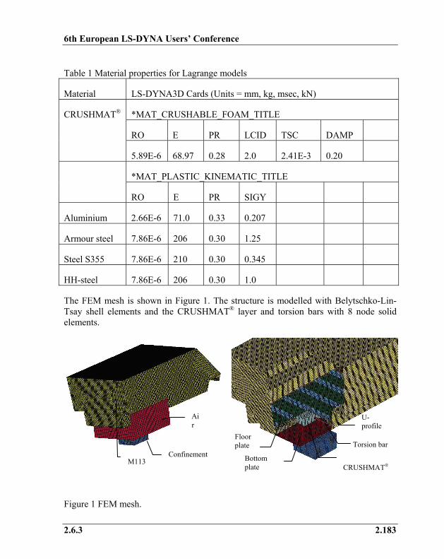
The FEM mesh is shown in Figure 1. The structure is modelled with Belytschko-Lin-Tsay shell elements and the CRUSHMAT® layer and torsion bars with 8 node solid elements.
Figure 1 FEM mesh.
Torsion bar
U-profile
CRUSHMAT®
Floor plate
Bottom plate
Confinement
Air
M113
6th European LS-DYNA Users’ Conference
2.184 2.6.3
The floor is fastened with bolts to the chassis. The bolting is modelled as spot welds with shear and axial force according to the bolts used in the full-scale test.
Underneath the steel armour floor is the CRUSHMAT® layer which is modelled with solid elements. Contacts are defined between the CRUSHMAT® and all neighbouring materials.
A mine placed in a confinement (steel pit) with a surrounding volume of air is modelled centrally beneath the crew compartment of the vehicle. The mine, confinement and surrounding air is modelled with ALE elements and connected to the Lagrange elements with the *CONSTRAINED_LAGRANGE_IN_SOLID card. The mine is modelled with material model *MAT_HIGH_EXPLOSIVE_BURN.
The goal of the model is to predict the reaction of the add-on armour exposed to an anti-tank mine and furthermore the overall rigid motion of the vehicle.
CRUSHMAT® MATERIAL MODELLING
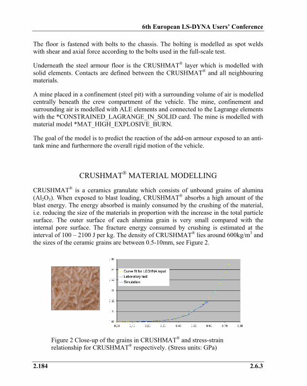
CRUSHMAT® is a ceramics granulate which consists of unbound grains of alumina (Al2O3). When exposed to blast loading, CRUSHMAT® absorbs a high amount of the blast energy. The energy absorbed is mainly consumed by the crushing of the material, i.e. reducing the size of the materials in proportion with the increase in the total particle surface. The outer surface of each alumina grain is very small compared with the internal pore surface. The fracture energy consumed by crushing is estimated at the interval of 100 – 2100 J per kg. The density of CRUSHMAT® lies around 600kg/m3 and the sizes of the ceramic grains are between 0.5-10mm, see Figure 2.
Figure 2 Close-up of the grains in CRUSHMAT® and stress-strain relationship for CRUSHMAT® respectively. (Stress units: GPa)
6th European LS-DYNA Users’ Conference
2.6.3 2.185
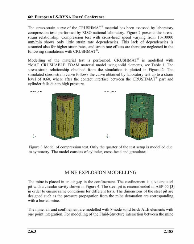
The stress-strain curve of the CRUSHMAT® material has been assessed by laboratory compression tests performed by RISØ national laboratory. Figure 2 presents the stress-strain relationship. Compression test with cross-head speed varying from 10-10000 mm/min shows only little strain rate dependencies. This lack of dependencies is assumed also for higher strain rates, and strain rate effects are therefore neglected in the following simulations with CRUSHMAT®.
Modelling of the material test is performed. CRUSHMAT® is modelled with *MAT_CRUSHABLE_FOAM material model using solid elements, see Table 1. The stress-strain relationship obtained from the simulation is plotted in Figure 2. The simulated stress-strain curve follows the curve obtained by laboratory test up to a strain level of 0.60, where after the contact interface between the CRUSHMAT® part and cylinder fails due to high pressure.
Figure 3 Model of compression test. Only the quarter of the test setup is modelled due to symmetry. The model consists of cylinder, cross-head and granulates.
MINE EXPLOSION MODELLING
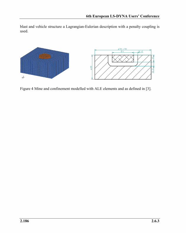
The mine is placed in an air gap in the confinement. The confinement is a square steel pit with a circular cavity shown in Figure 4. The steel pit is recommended in AEP-55 [3] in order to ensure same conditions for different tests. The dimensions of the steel pit are designed such as the pressure propagation from the mine detonation are corresponding with a buried mine.
The mine, air and confinement are modelled with 8-node solid brick ALE elements with one point integration. For modelling of the Fluid-Structure interaction between the mine
6th European LS-DYNA Users’ Conference
2.186 2.6.3
blast and vehicle structure a Lagrangian-Eulerian description with a penalty coupling is used.
Figure 4 Mine and confinement modelled with ALE elements and as defined in [3].
6th European LS-DYNA Users’ Conference
2.6.3 2.187
The explosive is C4. The properties for the explosive are found in literature [2]. It is modelled as a *MAT_HIGH_BURN_EXPLOSIVE, see Table 2.
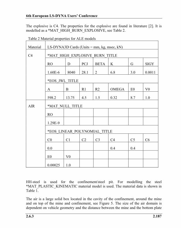
Table 2 Material properties for ALE models
Material LS-DYNA3D Cards (Units = mm, kg, msec, kN)
*MAT_HIGH_EXPLOSIVE_BURN_TITLE
RO D PCJ BETA K G SIGY
1.60E-6 8040 28.1 2 6.8 3.0 0.0011
*EOS_JWL_TITLE
A B R1 R2 OMEGA E0 V0
C4
598.2 13.75 4.5 1.5 0.32 8.7 1.0
*MAT_NULL_TITLE
RO
1.29E-9
*EOS_LINEAR_POLYNOMIAL_TITLE
C0 C1 C2 C3 C4 C5 C6
0.0 0.4 0.4
E0 V0
AIR
0.00025 1.0
HH-steel is used for the confinement/steel pit. For modelling the steel *MAT_PLASTIC_KINEMATIC material model is used. The material data is shown in Table 1.
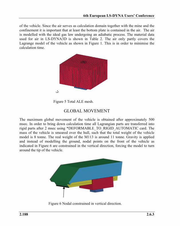
The air is a large solid box located in the cavity of the confinement, around the mine and on top of the mine and confinement, see Figure 5. The size of the air domain is dependent on vehicle geometry and the distance between the mine and the bottom plate
6th European LS-DYNA Users’ Conference
2.188 2.6.3
of the vehicle. Since the air serves as calculation domain together with the mine and the confinement it is important that at least the bottom plate is contained in the air. The air is modelled with the ideal gas law undergoing an adiabatic process. The material data used for air in LS-DYNA3D is shown in Table 2. The air only partly covers the Lagrange model of the vehicle as shown in Figure 1. This is in order to minimise the calculation time.
Figure 5 Total ALE mesh.
GLOBAL MOVEMENT
The maximum global movement of the vehicle is obtained after approximately 500 msec. In order to bring down calculation time all Lagrangian parts are transferred into rigid parts after 2 msec using *DEFORMABLE_TO_RIGID_AUTOMATIC card. The mass of the vehicle is smeared over the hull, such that the total weight of the vehicle model is 8 tonne. The real weight of the M113 is around 11 tonne. Gravity is applied and instead of modelling the ground, nodal points on the front of the vehicle as indicated in Figure 6 are constrained in the vertical direction, forcing the model to turn around the tip of the vehicle.
Figure 6 Nodal constrained in vertical direction.
6th European LS-DYNA Users’ Conference
2.6.3 2.189
FULL-SCALE TEST
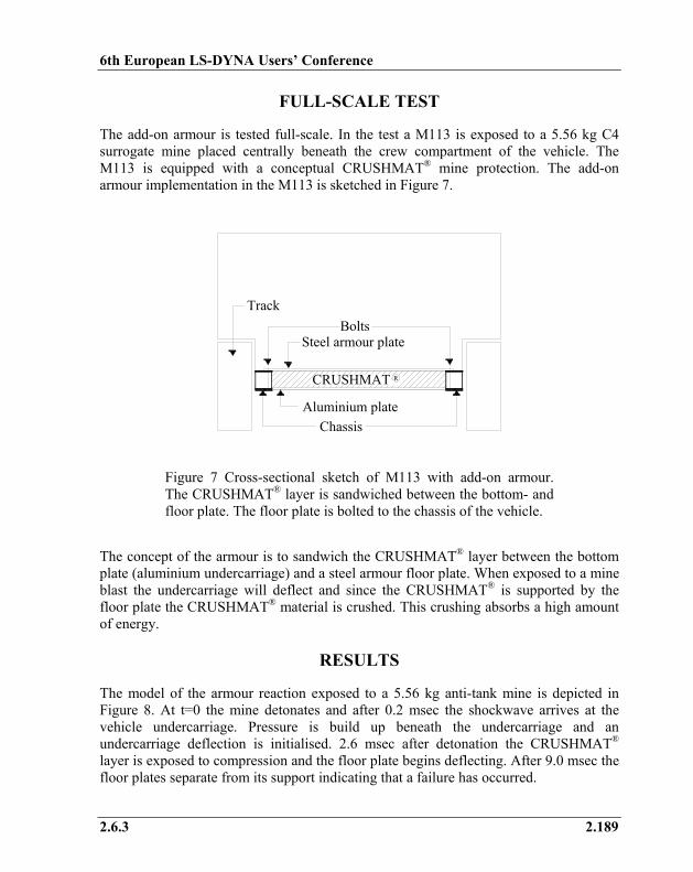
The add-on armour is tested full-scale. In the test a M113 is exposed to a 5.56 kg C4 surrogate mine placed centrally beneath the crew compartment of the vehicle. The M113 is equipped with a conceptual CRUSHMAT® mine protection. The add-on armour implementation in the M113 is sketched in Figure 7.
CRUSHMAT
BoltsSteel armour plate
Track
R
Aluminium plateChassis
Figure 7 Cross-sectional sketch of M113 with add-on armour. The CRUSHMAT® layer is sandwiched between the bottom- and floor plate. The floor plate is bolted to the chassis of the vehicle.
The concept of the armour is to sandwich the CRUSHMAT® layer between the bottom plate (aluminium undercarriage) and a steel armour floor plate. When exposed to a mine blast the undercarriage will deflect and since the CRUSHMAT® is supported by the floor plate the CRUSHMAT® material is crushed. This crushing absorbs a high amount of energy.
RESULTS
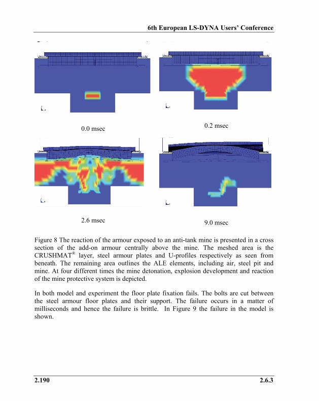
The model of the armour reaction exposed to a 5.56 kg anti-tank mine is depicted in Figure 8. At t=0 the mine detonates and after 0.2 msec the shockwave arrives at the vehicle undercarriage. Pressure is build up beneath the undercarriage and an undercarriage deflection is initialised. 2.6 msec after detonation the CRUSHMAT® layer is exposed to compression and the floor plate begins deflecting. After 9.0 msec the floor plates separate from its support indicating that a failure has occurred.
6th European LS-DYNA Users’ Conference
2.190 2.6.3
0.0 msec
0.2 msec
2.6 msec
9.0 msec
Figure 8 The reaction of the armour exposed to an anti-tank mine is presented in a cross section of the add-on armour centrally above the mine. The meshed area is the CRUSHMAT® layer, steel armour plates and U-profiles respectively as seen from beneath. The remaining area outlines the ALE elements, including air, steel pit and mine. At four different times the mine detonation, explosion development and reaction of the mine protective system is depicted.
In both model and experiment the floor plate fixation fails. The bolts are cut between the steel armour floor plates and their support. The failure occurs in a matter of milliseconds and hence the failure is brittle. In Figure 9 the failure in the model is shown.
6th European LS-DYNA Users’ Conference
2.6.3 2.191
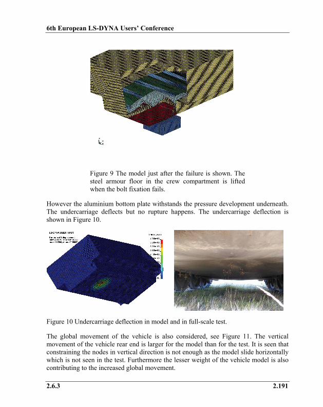
Figure 9 The model just after the failure is shown. The steel armour floor in the crew compartment is lifted when the bolt fixation fails.
However the aluminium bottom plate withstands the pressure development underneath. The undercarriage deflects but no rupture happens. The undercarriage deflection is shown in Figure 10.
Figure 10 Undercarriage deflection in model and in full-scale test.
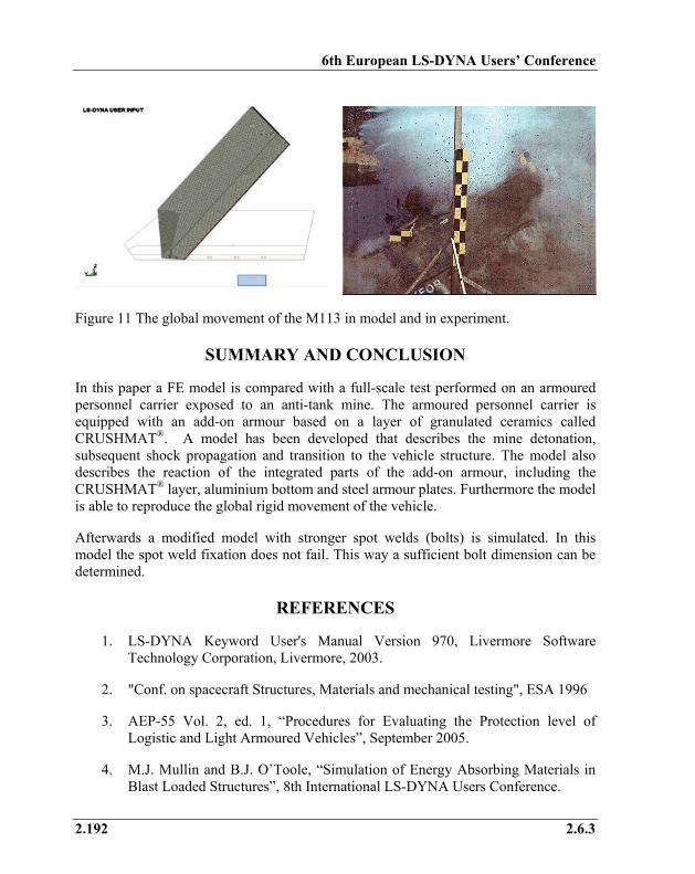
The global movement of the vehicle is also considered, see Figure 11. The vertical movement of the vehicle rear end is larger for the model than for the test. It is seen that constraining the nodes in vertical direction is not enough as the model slide horizontally which is not seen in the test. Furthermore the lesser weight of the vehicle model is also contributing to the increased global movement.
6th European LS-DYNA Users’ Conference
2.192 2.6.3
Figure 11 The global movement of the M113 in model and in experiment.
SUMMARY AND CONCLUSION
In this paper a FE model is compared with a full-scale test performed on an armoured personnel carrier exposed to an anti-tank mine. The armoured personnel carrier is equipped with an add-on armour based on a layer of granulated ceramics called CRUSHMAT®. A model has been developed that describes the mine detonation, subsequent shock propagation and transition to the vehicle structure. The model also describes the reaction of the integrated parts of the add-on armour, including the CRUSHMAT® layer, aluminium bottom and steel armour plates. Furthermore the model is able to reproduce the global rigid movement of the vehicle.
Afterwards a modified model with stronger spot welds (bolts) is simulated. In this model the spot weld fixation does not fail. This way a sufficient bolt dimension can be determined.
REFERENCES
1. LS-DYNA Keyword User's Manual Version 970, Livermore Software Technology Corporation, Livermore, 2003.
2. "Conf. on spacecraft Structures, Materials and mechanical testing", ESA 1996
3. AEP-55 Vol. 2, ed. 1, “Procedures for Evaluating the Protection level of Logistic and Light Armoured Vehicles”, September 2005.
4. M.J. Mullin and B.J. O’Toole, “Simulation of Energy Absorbing Materials in Blast Loaded Structures”, 8th International LS-DYNA Users Conference.