lancom outdoor wireless guide
DESCRIPTION
This document applies for all LANCOM Wireless Routers and LANCOM Access Points in combination with antennas of the AirLancer series and it provides general information on the outdoor operation of wireless LAN systems. Information on the installation and basic configuration of the various Wireless Routers, Access Points and antennas is available from the corresponding user manual.TRANSCRIPT
1106
23/0
908
LANCOM Systems GmbH
Adenauerstr. 20/B2
52146 Würselen
Germany
E-Mail: [email protected]
Internet www.lancom.eu
LANCOM Outdoor Wireless Guide
LAN
COM
Out
door
Wire
less
Gui
de
. . . c o n n e c t i n g y o u r b u s i n e s s
110623_LC-WLAN-OUTDOOR-IGUIDE_co1 1110623_LC-WLAN-OUTDOOR-IGUIDE_co1 1 02.09.2008 08:26:1202.09.2008 08:26:12
LANCOM Outdoor Wireless Guide
© 2009 LANCOM Systems GmbH, Wuerselen (Germany). All rights reserved.
While the information in this manual has been compiled with great care, it may not be deemed an assurance of productcharacteristics. LANCOM Systems shall be liable only to the degree specified in the terms of sale and delivery.
The reproduction and distribution of the documentation and software included with this product is subject to written per-mission by LANCOM Systems. We reserve the right to make any alterations that arise as the result of technical develop-ment.
All explanations and documents for registration of the products you find in the appendix of this documentation, if theywere present at the time of printing.
Trademarks
Windows®, Windows Vista™, Windows XP® and Microsoft® are registered trademarks of Microsoft, Corp.
The LANCOM Systems logo, LCOS and the name LANCOM are registered trademarks of LANCOM Systems GmbH. All othernames mentioned may be trademarks or registered trademarks of their respective owners.
This product includes software developed by the OpenSSL Project for use in the OpenSSL Toolkit http://www.openssl.org/.
This product includes cryptographic software written by Eric Young ([email protected]).
This product includes software developed by the NetBSD Foundation, Inc. and its contributors.
This product includes the LZMA SDK written by Igor Pavlov.
Subject to change without notice. No liability for technical errors or omissions.
LANCOM Systems GmbH
Adenauerstr. 20/B2
52146 Wuerselen
Germany
www.lancom.eu
Wuerselen, Februar 2009
110623/0209
LANCOM Outdoor Wireless Guide
� Preface
EN
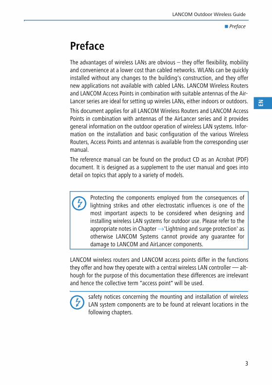
PrefaceThe advantages of wireless LANs are obvious – they offer flexibility, mobilityand convenience at a lower cost than cabled networks. WLANs can be quicklyinstalled without any changes to the building's construction, and they offernew applications not available with cabled LANs. LANCOM Wireless Routersand LANCOM Access Points in combination with suitable antennas of the Air-Lancer series are ideal for setting up wireles LANs, either indoors or outdoors.
This document applies for all LANCOM Wireless Routers and LANCOM AccessPoints in combination with antennas of the AirLancer series and it providesgeneral information on the outdoor operation of wireless LAN systems. Infor-mation on the installation and basic configuration of the various WirelessRouters, Access Points and antennas is available from the corresponding usermanual.
The reference manual can be found on the product CD as an Acrobat (PDF)document. It is designed as a supplement to the user manual and goes intodetail on topics that apply to a variety of models.
LANCOM wireless routers and LANCOM access points differ in the functionsthey offer and how they operate with a central wireless LAN controller — alt-hough for the purpose of this documentation these differences are irrelevantand hence the collective term "access point" will be used.
safety notices concerning the mounting and installation of wirelessLAN system components are to be found at relevant locations in thefollowing chapters.
Protecting the components employed from the consequences oflightning strikes and other electrostatic influences is one of themost important aspects to be considered when designing andinstalling wireless LAN systems for outdoor use. Please refer to theappropriate notes in Chapter →'Lightning and surge protection' asotherwise LANCOM Systems cannot provide any guarantee fordamage to LANCOM and AirLancer components.
3
LANCOM Outdoor Wireless Guide
� Preface
EN
This documentation was created by …
... several members of our staff from a variety of departments in order toensure you the best possible support when using your LANCOM product.
Should you find any errors, or if you would like to suggest improvements, ple-ase do not hesitate to send an e-mail directly to: [email protected]
Our online services www.lancom.eu are available to you around theclock if you have any questions on the content in this manual, or if yourequire any further support. The area 'Support' will help you withmany answers to frequently asked questions (FAQs). Furthermore, theknowledgebase offers you a large reserve of information. The latestdrivers, firmware, utilities and documentation are constantly availablefor download. In addition, LANCOM Support is available. For telephone numbersand contact addresses for LANCOM Support, please refer to the enc-losed leaflet or the LANCOM Systems Web site.
Information symbols
Very important instructions. Failure to observe these may result in damage.
Important instruction that should be observed.
Additional information that may be helpful but is not essential.
4
LANCOM Outdoor Wireless Guide
� Contents
EN
Contents
1 Introduction 7
1.1 Application scenarios 71.1.1 Campus coverage 71.1.2 Hotspot 81.1.3 Data transfer to mobile objects in industrial environments.
81.1.4 Wireless link (point-to-point) 91.1.5 Wireless Distribution System (point-to-multipoint) 101.1.6 Wireless links in relay mode 11
1.2 Components of the wireless LAN system 111.2.1 Access Points and Wireless Router 111.2.2 Power supply to the Access Point 121.2.3 External antennas 121.2.4 Lightning and surge protection equipment 14
1.3 Selecting the frequency band 151.3.1 2.4 or 5 GHz band 151.3.2 Special regulations for the 5 GHz band 16
2 Setting up point- to-point connections 21
2.1 Antenna selection with the LANCOM Antenna Calculator 222.1.1 Data throughput and range 232.1.2 Data throughput: Gross vs. net 25
2.2 Geometric dimensioning of outdoor wireless network links 25
2.3 Antenna alignment for P2P operations 28
2.4 Measuring wireless bridges 30
3 Lightning and surge protection 31
3.1 Where do lightning discharges come from? 31
3.2 External lightning protection 32
3.3 Internal lightning protection 333.3.1 Selecting the lightning and surge protective components
353.3.2 Example applications 37
5
LANCOM Outdoor Wireless Guide
� Contents
EN
4 Installation 42
4.1 Safety advice 42
4.2 Mounting the Access Points 434.2.1 Selecting the location for mounting 434.2.2 Wall mounting 444.2.3 Pole mounting 444.2.4 Top-hat rail mounting 45
4.3 Mounting antennas 454.3.1 Selecting the location for mounting 464.3.2 Wall mounting 464.3.3 Mast mounting 47
4.4 Mounting the lightning rods 474.4.1 Dimensioning of the lightning rod 484.4.2 Distance to the components at risk 484.4.3 Lightning charge conduction (grounding) 49
5 Appendix 50
5.1 Antenna gain, EIRP and antenna radiation characteristics 50
5.2 Troubleshooting 55
6 Index 57
6
LANCOM Outdoor Wireless Guide
� Chapter 1: Introduction
EN
1 IntroductionThis chapter presents the basic application scenarios for wireless LAN outdoorsystems. These include, for example campus coverage, industrial applicationsand wireless links. We also list the components required to set up a wirelessLAN system outdoors.
1.1 Application scenarios
Wireless LAN systems can act as an extension to or even as a replacement forcabled networks. In some cases wireless LANs even provide completely newapplication possibilities, which can mean a major advance in the way work isorganized, or significant cost savings.
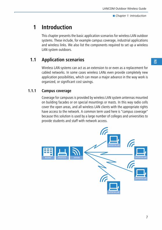
1.1.1 Campus coverage
Coverage for campuses is provided by wireless LAN system antennas mountedon building facades or on special mountings or masts. In this way radio cellscover the open areas, and all wireless LAN clients with the appropriate rightshave access to the network. A common term used here is "campus coverage"because this solution is used by a large number of colleges and universities toprovide students and staff with network access.
LAPTOP/W-LAN
WLAN Router ANTENNABUILDING LAPTOP/W-LAN
LAPTOP/W-LAN
LAPTOP/W-LAN
7
LANCOM Outdoor Wireless Guide
� Chapter 1: Introduction
EN
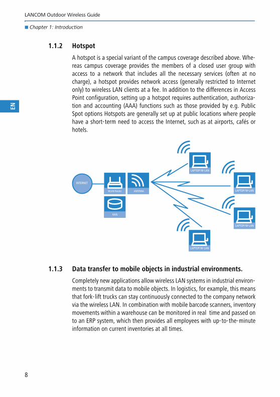
1.1.2 Hotspot
A hotspot is a special variant of the campus coverage described above. Whe-reas campus coverage provides the members of a closed user group withaccess to a network that includes all the necessary services (often at nocharge), a hotspot provides network access (generally restricted to Internetonly) to wireless LAN clients at a fee. In addition to the differences in AccessPoint configuration, setting up a hotspot requires authentication, authoriza-tion and accounting (AAA) functions such as those provided by e.g. PublicSpot options Hotspots are generally set up at public locations where peoplehave a short-term need to access the Internet, such as at airports, cafés orhotels.
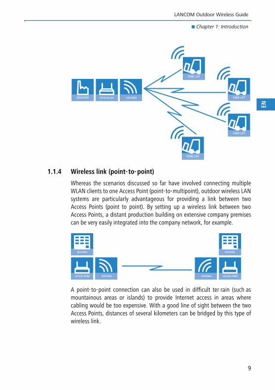
1.1.3 Data transfer to mobile objects in industrial environments.
Completely new applications allow wireless LAN systems in industrial environ-ments to transmit data to mobile objects. In logistics, for example, this meansthat fork-lift trucks can stay continuously connected to the company networkvia the wireless LAN. In combination with mobile barcode scanners, inventorymovements within a warehouse can be monitored in real time and passed onto an ERP system, which then provides all employees with up-to-the-minuteinformation on current inventories at all times.
LAPTOP/W-LAN
WLAN Router ANTENNA LAPTOP/W-LAN
LAPTOP/W-LAN
LAPTOP/W-LAN
AAA
INTERNET
8
LANCOM Outdoor Wireless Guide
� Chapter 1: Introduction
EN
1.1.4 Wireless link (point-to-point)
Whereas the scenarios discussed so far have involved connecting multipleWLAN clients to one Access Point (point-to-multipoint), outdoor wireless LANsystems are particularly advantageous for providing a link between twoAccess Points (point to point). By setting up a wireless link between twoAccess Points, a distant production building on extensive company premisescan be very easily integrated into the company network, for example.
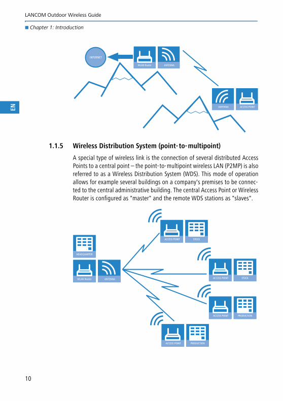
A point-to-point connection can also be used in difficult ter rain (such asmountainous areas or islands) to provide Internet access in areas wherecabling would be too expensive. With a good line of sight between the twoAccess Points, distances of several kilometers can be bridged by this type ofwireless link.
WLAN Router ANTENNAINDUSTRY
FORK LIFT
FORK LIFT
FORK LIFT
FORK LIFT
ACCESS POINT ANTENNA
BUILDING
ACCESS POINTANTENNA
BUILDING
9
LANCOM Outdoor Wireless Guide
� Chapter 1: Introduction
EN
1.1.5 Wireless Distribution System (point-to-multipoint)
A special type of wireless link is the connection of several distributed AccessPoints to a central point – the point-to-multipoint wireless LAN (P2MP) is alsoreferred to as a Wireless Distribution System (WDS). This mode of operationallows for example several buildings on a company's premises to be connec-ted to the central administrative building. The central Access Point or WirelessRouter is configured as "master" and the remote WDS stations as "slaves".
WLAN Router ANTENNA
ACCESS POINTANTENNA
INTERNET
WLAN Router ANTENNA
HEADQUARTER
ACCESS POINT
ACCESS POINT
ACCESS POINT
ACCESS POINT PRODUCTION
PRODUCTION
STOCK
STOCK
10
LANCOM Outdoor Wireless Guide
� Chapter 1: Introduction
EN
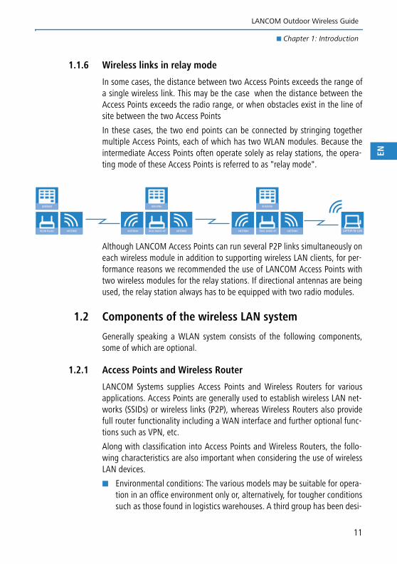
1.1.6 Wireless links in relay mode
In some cases, the distance between two Access Points exceeds the range ofa single wireless link. This may be the case when the distance between theAccess Points exceeds the radio range, or when obstacles exist in the line ofsite between the two Access Points
In these cases, the two end points can be connected by stringing togethermultiple Access Points, each of which has two WLAN modules. Because theintermediate Access Points often operate solely as relay stations, the opera-ting mode of these Access Points is referred to as "relay mode".
Although LANCOM Access Points can run several P2P links simultaneously oneach wireless module in addition to supporting wireless LAN clients, for per-formance reasons we recommended the use of LANCOM Access Points withtwo wireless modules for the relay stations. If directional antennas are beingused, the relay station always has to be equipped with two radio modules.
1.2 Components of the wireless LAN system
Generally speaking a WLAN system consists of the following components,some of which are optional.
1.2.1 Access Points and Wireless Router
LANCOM Systems supplies Access Points and Wireless Routers for variousapplications. Access Points are generally used to establish wireless LAN net-works (SSIDs) or wireless links (P2P), whereas Wireless Routers also providefull router functionality including a WAN interface and further optional func-tions such as VPN, etc.
Along with classification into Access Points and Wireless Routers, the follo-wing characteristics are also important when considering the use of wirelessLAN devices.
� Environmental conditions: The various models may be suitable for opera-tion in an office environment only or, alternatively, for tougher conditionssuch as those found in logistics warehouses. A third group has been desi-
DUAL RADIO AP ANTENNE
BUILDING
ANTENNA DUAL RADIO AP ANTENNA
BUILDING
ANTENNAWLAN Router ANTENNE
GEBÄUDE
LAPTOP/W-LAN
11
LANCOM Outdoor Wireless Guide
� Chapter 1: Introduction
EN
gned for operation under extreme weather conditions, i.e. water resistant,and some are for operation in extreme temperatures.
� Standards supported: Depending on model type, the Access Points sup-port the following standards: IEEE 802.11a (5 GHz band), IEEE 802.11b orIEEE 802.11g (2.4 GHz band) or IEEE 802.11n (2.4 and 5 GHz bands). The5-GHz band is highly suitable for directional radio links due to the higherperformance.
Please refer to the appendix in this manual for more information onthe frequency bands and their permitted use in different countries.
� Number of wireless LAN modules: For operating directional radio linksover distances that exceed the range of a single P2P connection, i.e. whenoperating a relay, devices fitted with two wireless LAN modules arerequired.
1.2.2 Power supply to the Access Point
An alternative to supplying power to an Access Point via its own internalpower adapter is to use Power over Ethernet (PoE). PoE-capable networkdevices can be neatly provided with power over LAN cabling. A power supplyfor each access point is therefore not necessary, significantly reducing theeffort of installation.
Power is fed into the LAN at a central location by using a PoE injector, a powerhub or power switch. It is important that all eight wires are connected in theLAN cabling.
PoE injectors available on the market support different standards andtechnical specifications depending on the model. Please ensure thatthe PoE injector is suitable for the Access Point being used. Not alldevices operate with the PoE standard IEEE 802.3af.
1.2.3 External antennas
Most LANCOM Access Points are supplied with an antenna. However, formany of the outdoor applications relevant to this documentation, additionalexternal antennas are necessary to meet the specialized demands. The follo-wing sections contain a brief description of the different types of antenna:
Please refer to the appendix in this manual for more information onthe typical antenna characteristics of antenna gain, EIRP and radia-tion patterns.
12
LANCOM Outdoor Wireless Guide
� Chapter 1: Introduction
EN
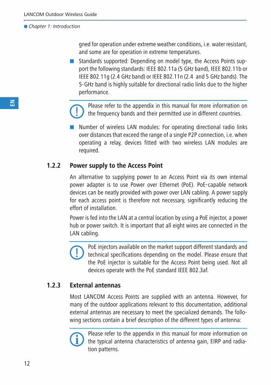
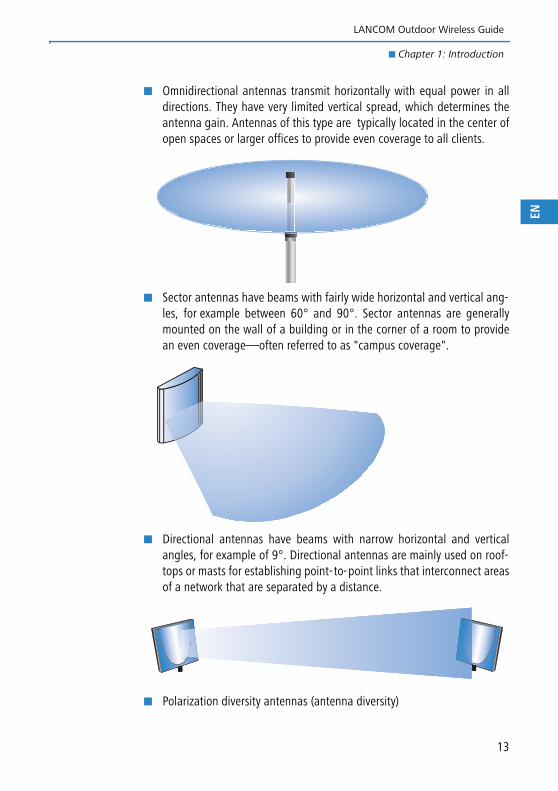
� Omnidirectional antennas transmit horizontally with equal power in alldirections. They have very limited vertical spread, which determines theantenna gain. Antennas of this type are typically located in the center ofopen spaces or larger offices to provide even coverage to all clients.
� Sector antennas have beams with fairly wide horizontal and vertical ang-les, for example between 60° and 90°. Sector antennas are generallymounted on the wall of a building or in the corner of a room to providean even coverage—often referred to as "campus coverage".
� Directional antennas have beams with narrow horizontal and verticalangles, for example of 9°. Directional antennas are mainly used on roof-tops or masts for establishing point-to-point links that interconnect areasof a network that are separated by a distance.
� Polarization diversity antennas (antenna diversity)
13
LANCOM Outdoor Wireless Guide
� Chapter 1: Introduction
EN
Among other things, the transmission of radio signals can suffer from sig-nificant signal losses due to reflection and scatter . When electromagneticwaves overlap at the point of reception, the strength of the signals maybe reduced or completely obliterated (interference). Transmission qualitycan be improved with so-called "diversity" methods.
The polarization diversity method makes use of the electromagnetic pola-rization of the radio waves. The transmitter broadcasts the wireless LANsignals as linearly polarized waves with a fixed direction of polarization.The polarization may be modified over the radio link by reflection and dif-fraction so that signals reach the receiver with differing polarization. Pola-rization diversity antennas use two signals with polarization turnedthrough 90°. The two antenna signals result in genuinely improved per-formance with conventional diversity antennas since the stronger of thetwo signals can be used.
MIMO technology (multiple input, multiple output) used in wireless LANstandard 802.11n goes a step further. These multiple receivers and trans-mitters can use the horizontally and vertically polarized waves as inde-pendent transmission paths and thus transmit double the amount of dataon one frequency.
Two antennas are connected to the access point's main and auxiliary portsin order to receive both signals.
For further information on the subject of 'Polarization diversity anten-nas (antenna diversity)' refer to the LCOS reference manual.
1.2.4 Lightning and surge protection equipment
Besides the central components (access point, antenna and power supply) themost important accessories in a wireless LAN system are those for lightningand power surge protection. Lightning and other electrostatic occurrences inthe atmosphere can impinge on the wireless LAN system in different ways andcause harm to people, machines and equipment. The lightning and surge pro-tection components guard against the effects of electrostatic discharge orreduce the surges to a level that is harmless for people and equipment.
Please refer to Chapter → 'Lightning and surge protection'.
14
LANCOM Outdoor Wireless Guide
� Chapter 1: Introduction
EN
1.3 Selecting the frequency band
1.3.1 2.4 or 5 GHz band
One of the first steps in the planning of a wireless LAN system is to determinewhich frequency band is to be used. The following aspects are helpful for deci-sion making:
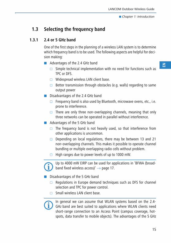
� Advantages of the 2.4 GHz band
� Simple technical implementation with no need for functions such asTPC or DFS.
� Widespread wireless LAN client base.
� Better transmission through obstacles (e.g. walls) regarding to sameoutput power
� Disadvantages of the 2.4 GHz band
� Frequency band is also used by Bluetooth, microwave ovens, etc., i.e.prone to interference.
� There are only three non-overlapping channels, meaning that onlythree networks can be operated in parallel without interference.
� Advantages of the 5 GHz band
� The frequency band is not heavily used, so that interference fromother applications is uncommon.
� Depending on local regulations, there may be between 13 and 21non-overlapping channels. This makes it possible to operate channelbundling or multiple overlapping radio cells without problem.
� High ranges due to power levels of up to 1000 mW.
Up to 4000 mW EIRP can be used for applications in ’BFWA (broad-band fixed wireless access)’ → page 17.
� Disadvantages of the 5 GHz band
� Regulations in Europe demand techniques such as DFS for channelselection and TPC for power control.
� Small wireless LAN client base.
In general we can assume that WLAN systems based on the 2.4-GHz band are best suited to applications where WLAN clients needshort-range connection to an Access Point (campus coverage, hot-spots, data transfer to mobile objects). The advantages of the 5 GHz
15
LANCOM Outdoor Wireless Guide
� Chapter 1: Introduction
EN
band lie mainly with point-to-point systems, whereby two AccessPoints are connected by a wireless link over longer distances.
1.3.2 Special regulations for the 5 GHz band
With the 802.11h enhancement of September 2003, the private use of the5 GHz band was finally possible even outside closed spaces. To protect mili-tary applications in the 5 GHz band, the DFS (Dynamic Frequency Selection)and TPC (Transmission Power Control) procedures were prescribed. However,when using DFS and TPC with a maximum of 1000 mW (or 4000 mW for com-mercial network operators in compliance with "Broadband Fixed WirelessAccess" regulations), much higher transmission powers can be operated thanallowed by previous standards.
� Dynamic Frequency Selection – DFS
Certain requirements must be observed for the outdoor operation of 5-GHz WLANs if you wish to utilize the maximum permitted performance of 1 or4 watts. It is vital to avoid interference with radar systems that are active inthis spectrum (e.g. meteorological, military). For this reason the Europeanregulatory authority ETSI requires WLAN devices operating at 5 GHz to employthe dynamic frequency selection (DFS) mechanism.
This ensures that radar and WLAN systems can co-exist without interferingwith one another and that capacity utilization is spread evenly across avai-lable frequencies. When starting a WLAN wireless cell, the access point mustcheck all channels for the presence of radar systems. The check requires aninactive period of one minute, during which the wireless cell cannot be used.As a result, the access point generates a list of radar-free channels which isvalid for 24 hours. The best possible channel for operation is selected fromthis list. During operation, the current channel is continuously checked forradar activity.
If a radar system subsequently starts operation, the channel must be releasedimmediately. In this case, the access point selects the next best availablechannel, informs the participants in the wireless cell of the impending change,and switches the channel.
The currently selected channel can be used for any length of time,unless radar signals are detected or if the radio cell is restarted(e.g. due to device reconfiguration, firmware upload or reboot).
If the system is able to respond to a channel switch instantaneously,the check must be repeated within 24 hours following a one-minute
16
LANCOM Outdoor Wireless Guide
� Chapter 1: Introduction
EN
period of inactivity. The parameter "DFS Rescan Hours" (LCOS menutree under "Setup/Interfaces/WLAN/Radio settings") allows a time tobe set for conducting the channel check (assuming that the time isavailable, for example via NTP).
DFS is stipulated for the frequency ranges from 5250 - 5350 MHz, 5470 -5725 MHz and from 5775 – 5875 (BFWA). It is optional for the frequencyrange of 5150 - 5250 MHz.
� Transmission Power Control – TPC
Automatic adjustment of the transmission power reduces radio interfe-rence.
Without DFS and TPC, a maximum of only 200 mW EIRP is permitted.When operating DFS and TPC, a maximum of 200 mW (5150 to5350 MHz) and 1000 mW EIRP (5470 to 5725 MHz) is permitted as trans-mitting power (compare 100 mW for 802.11b/g, 2.4 GHz, where DFS andTPC are unnecessary). The higher maximum transmission power not onlycompensates for the higher attenuation of 5 GHz radio waves in air, it alsomakes significantly longer ranges possible than in the 2.4 GHz range.
� BFWA (broadband fixed wireless access)
In Germany in July, 2007, the Federal Network Agency released additionalfrequencies for broadband fixed wireless bridges in the 5 GHz band.These additional frequencies located in the range between 5755 MHz -5875 MHz are also referred to as BFWA (Broadband Fixed WirelessAccess). The additional frequencies are intended for long-distance point-to-point (P2P) or point-to-multipoint (P2M) links used for providing high-speed Internet access to other users from a central node. This method isintended to provide rural areas with high-speed Internet access.
The operation of BFWA is restricted to commercial providers only. Thereare no charges for using these frequencies, but registration is required bythe Federal Network Agency. This band covers 120 MHz and offers 6channels with a bandwidth of 20 MHz each. Maximum transmissionpower is 36 dBm or 4000 mW. TPC and DFS have to be used when ope-rating BFWA links.
Available channels in the 5 GHz band
In the available frequency range of 5.13 to 5.875 GHz, the following channelsare available in Europe, divided into frequency ranges to which different con-ditions of use can apply:
17
LANCOM Outdoor Wireless Guide
� Chapter 1: Introduction
EN
� 5150 -5350 MHz (channels 36, 40, 44 and 48)
� 5250 -5350 MHz (channels 52, 56, 60 and 64)
� 5470 - 5725 MHz (channels 100, 104, 108, 112, 116, 132, 136 and 140)
� 5755 - 5875 MHz
� Channels 151, 155, 159 , 163, 167: In Germany is for commercial useonly and only in combination with DFS (BFWA).
� Channels 149, 153, 157, 161, 165: For FCC use in the USA, withoutDFS.
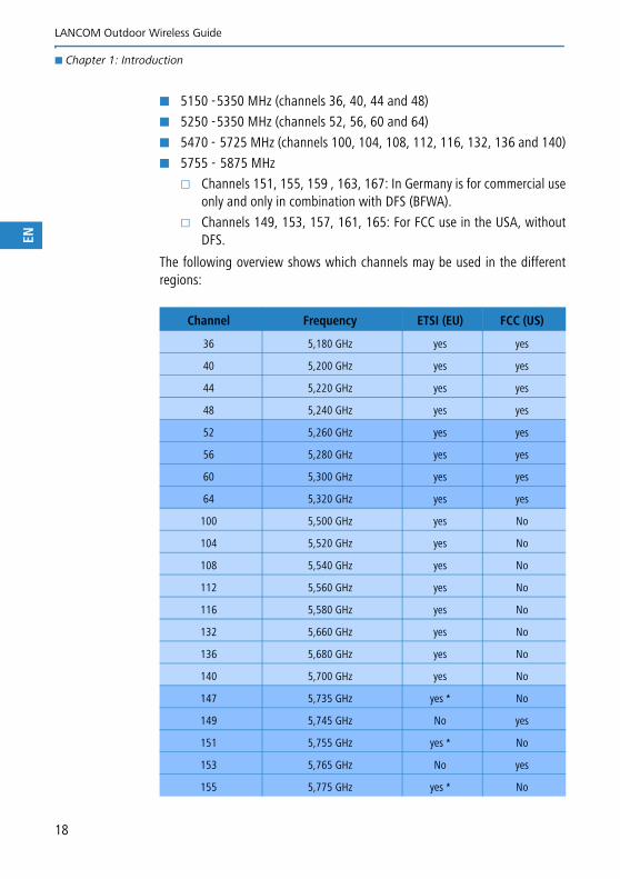
The following overview shows which channels may be used in the differentregions:
Channel Frequency ETSI (EU) FCC (US)
36 5,180 GHz yes yes
40 5,200 GHz yes yes
44 5,220 GHz yes yes
48 5,240 GHz yes yes
52 5,260 GHz yes yes
56 5,280 GHz yes yes
60 5,300 GHz yes yes
64 5,320 GHz yes yes
100 5,500 GHz yes No
104 5,520 GHz yes No
108 5,540 GHz yes No
112 5,560 GHz yes No
116 5,580 GHz yes No
132 5,660 GHz yes No
136 5,680 GHz yes No
140 5,700 GHz yes No
147 5,735 GHz yes * No
149 5,745 GHz No yes
151 5,755 GHz yes * No
153 5,765 GHz No yes
155 5,775 GHz yes * No
18
LANCOM Outdoor Wireless Guide
� Chapter 1: Introduction
EN
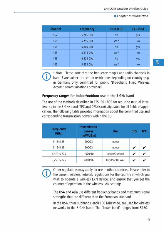
* Note: Please note that the frequency ranges and radio channels inband 3 are subject to certain restrictions depending on country (e.g.in Germany only permitted for public "Broadband Fixed WirelessAccess" communications providers).
Frequency ranges for indoor/outdoor use in the 5 GHz band
The use of the methods described in ETSI 301 893 for reducing mutual inter-ference in the 5 GHz band (TPC and DFS) is not stipulated for all fields of appli-cation. The following table provides information about the permitted use andcorresponding transmission powers within the EU:
Other regulations may apply for use in other countries. Please refer tothe current wireless network regulations for the country in which youwish to operate a wireless LAN device, and ensure that you set thecountry of operation in the wireless LAN settings.
The USA and Asia use different frequency bands and maximum signalstrengths that are different than the European standard.
In the USA, three subbands, each 100 MHz wide, are used for wirelessnetworks in the 5 GHz band. The "lower band" ranges from 5150 -
157 5,785 GHz No yes
159 5,795 GHz yes * No
161 5,805 GHz No yes
163 5,815 GHz yes * No
165 5,825 GHz No yes
167 5.835 GHz yes * No
Frequency(GHz)
Transmission-power
(mW/dBm)Use DFS TPC
5,15-5,25 200/23 Indoor
5,15-5,35 200/23 Indoor ✔ ✔
5,470-5,725 1000/30 Indoor/Outdoor ✔ ✔
5,755-5,875 4000/36 Outdoor (BFWA) ✔ ✔
Channel Frequency ETSI (EU) FCC (US)
19
LANCOM Outdoor Wireless Guide
� Chapter 1: Introduction
EN
5250 MHz, the "middle band" ranges from 5250 - 5350 MHz and the"upper band" ranges from 5725 - 5825 MHz. In the lower band, amaximum average EIRP of 50 mW is permitted; in the middle bandthis is 250 mW and 1 W in the upper band.
In Japan, the use of the 5 GHz band is possible to a limited extent: Thelower band of 5150 - 5250 MHz only is approved for private use.
20
LANCOM Outdoor Wireless Guide
� Chapter 2: Setting up point- to- point connections
EN
2 Setting up point-to-point connectionsThis chapter introduces the basic principles involved in designing point-to-point links and provides tips on aligning the antennas.
Please refer to the appendix for information on the frequency rangesused. Instructions on the configuration of the Access Points are to befound in the documentation for the device and in the LCOS referencemanual.
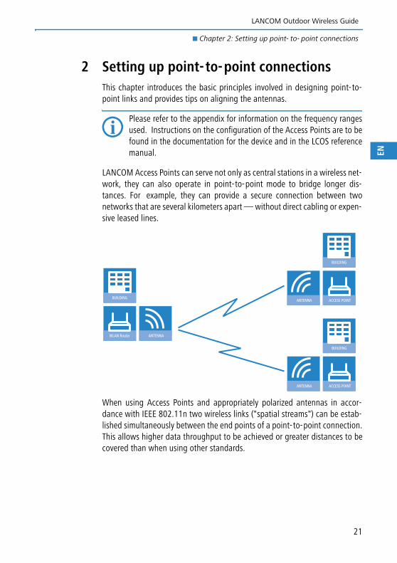
LANCOM Access Points can serve not only as central stations in a wireless net-work, they can also operate in point-to-point mode to bridge longer dis-tances. For example, they can provide a secure connection between twonetworks that are several kilometers apart — without direct cabling or expen-sive leased lines.
When using Access Points and appropriately polarized antennas in accor-dance with IEEE 802.11n two wireless links ("spatial streams") can be estab-lished simultaneously between the end points of a point-to-point connection.This allows higher data throughput to be achieved or greater distances to becovered than when using other standards.
WLAN Router ANTENNA
BUILDINGACCESS POINTANTENNA
BUILDING
ACCESS POINTANTENNA
BUILDING
21
LANCOM Outdoor Wireless Guide
� Chapter 2: Setting up point- to- point connections
EN
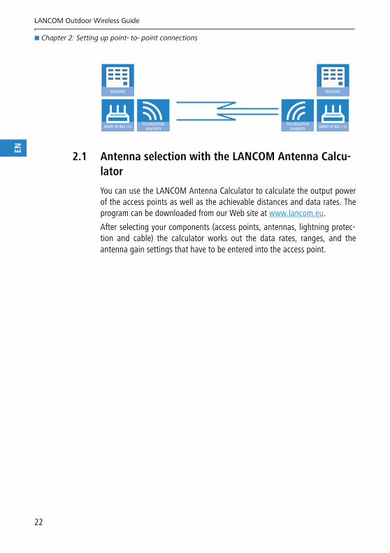
2.1 Antenna selection with the LANCOM Antenna Calcu-lator
You can use the LANCOM Antenna Calculator to calculate the output powerof the access points as well as the achievable distances and data rates. Theprogram can be downloaded from our Web site at www.lancom.eu.
After selecting your components (access points, antennas, lightning protec-tion and cable) the calculator works out the data rates, ranges, and theantenna gain settings that have to be entered into the access point.
MIMO AP 802.11nPOLARIZATION
DIVERSITY
BUILDING
MIMO AP 802.11nPOLARISATION
DIVERSITY
BUILDING
22
LANCOM Outdoor Wireless Guide
� Chapter 2: Setting up point- to- point connections
EN
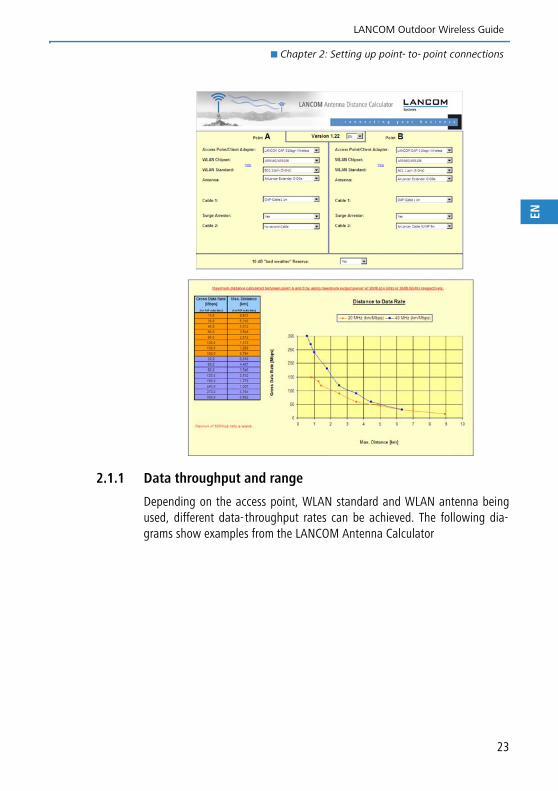
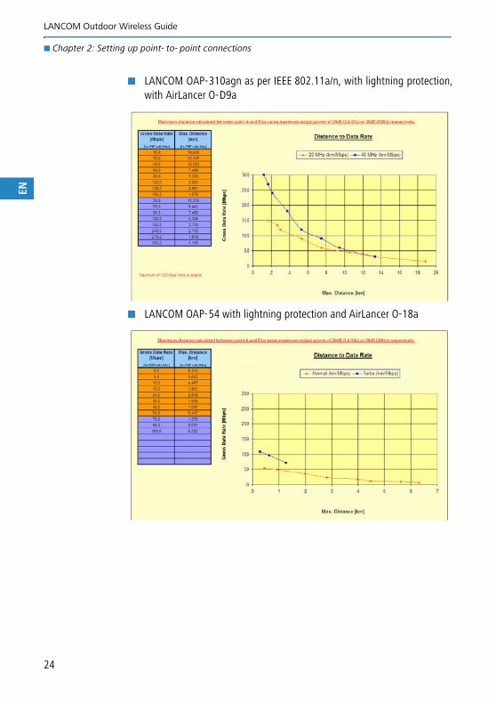
2.1.1 Data throughput and range
Depending on the access point, WLAN standard and WLAN antenna beingused, different data-throughput rates can be achieved. The following dia-grams show examples from the LANCOM Antenna Calculator
23
LANCOM Outdoor Wireless Guide
� Chapter 2: Setting up point- to- point connections
EN
� LANCOM OAP-310agn as per IEEE 802.11a/n, with lightning protection,with AirLancer O-D9a
� LANCOM OAP-54 with lightning protection and AirLancer O-18a
24
LANCOM Outdoor Wireless Guide
� Chapter 2: Setting up point- to- point connections
EN
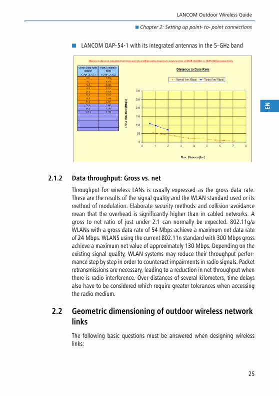
� LANCOM OAP-54-1 with its integrated antennas in the 5-GHz band
2.1.2 Data throughput: Gross vs. net
Throughput for wireless LANs is usually expressed as the gross data rate.These are the results of the signal quality and the WLAN standard used or itsmethod of modulation. Elaborate security methods and collision avoidancemean that the overhead is significantly higher than in cabled networks. Agross to net ratio of just under 2:1 can normally be expected. 802.11g/aWLANs with a gross data rate of 54 Mbps achieve a maximum net data rateof 24 Mbps. WLANS using the current 802.11n standard with 300 Mbps grossachieve a maximum net value of approximately 130 Mbps. Depending on theexisting signal quality, WLAN systems may reduce their throughput perfor-mance step by step in order to counteract impairments in radio signals. Packetretransmissions are necessary, leading to a reduction in net throughput whenthere is radio interference. Over distances of several kilometers, time delaysalso have to be considered which require greater tolerances when accessingthe radio medium.
2.2 Geometric dimensioning of outdoor wireless network links
The following basic questions must be answered when designing wirelesslinks:
25
LANCOM Outdoor Wireless Guide
� Chapter 2: Setting up point- to- point connections
EN
� Which antennas are necessary for the desired application? Answers tothese questions can be found with the help of the LANCOM Antenna Cal-culator (’Antenna selection with the LANCOM Antenna Calculator’→ page 22).
� How do the antennas have to be positioned to ensure problem-free con-nections?
� What performance characteristics do the antennas need to ensure suffi-cient data throughput within the legal limits?
Positioning the antennas
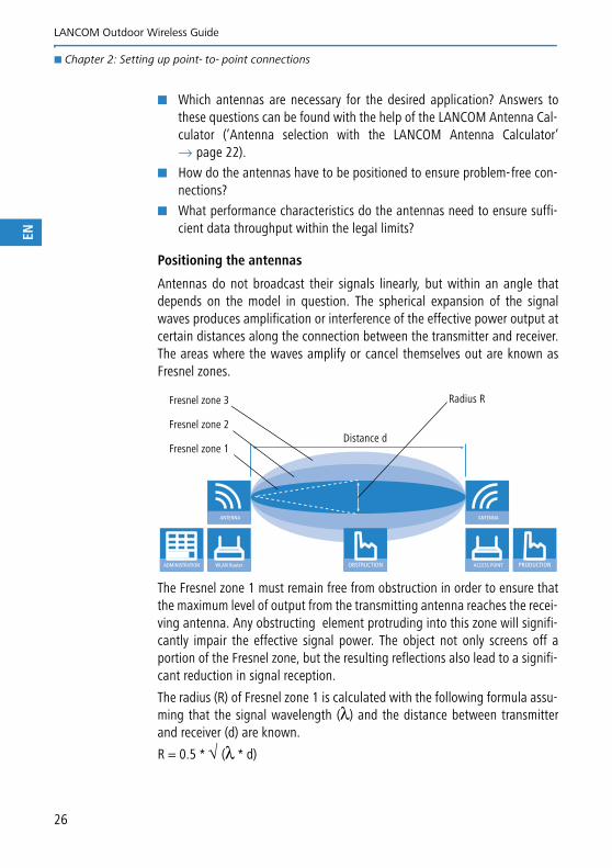
Antennas do not broadcast their signals linearly, but within an angle thatdepends on the model in question. The spherical expansion of the signalwaves produces amplification or interference of the effective power output atcertain distances along the connection between the transmitter and receiver.The areas where the waves amplify or cancel themselves out are known asFresnel zones.
The Fresnel zone 1 must remain free from obstruction in order to ensure thatthe maximum level of output from the transmitting antenna reaches the recei-ving antenna. Any obstructing element protruding into this zone will signifi-cantly impair the effective signal power. The object not only screens off aportion of the Fresnel zone, but the resulting reflections also lead to a signifi-cant reduction in signal reception.
The radius (R) of Fresnel zone 1 is calculated with the following formula assu-ming that the signal wavelength (λ) and the distance between transmitterand receiver (d) are known.
R = 0.5 * √ (λ * d)
WLAN Router
ANTENNA
ADMINISTRATION ACCESS POINT
ANTENNA
PRODUCTIONOBSTRUCTION
Fresnel zone 1
Fresnel zone 2
Fresnel zone 3 Radius R
Distance d
26
LANCOM Outdoor Wireless Guide
� Chapter 2: Setting up point- to- point connections
EN
27
The wavelength in the 2.4 GHz band is approx. 0.125 m, in the 5 GHz bandapprox. 0.05 m.
Example: With a separating distance of 4 km between the two antennae, theradius of Fresnel zone 1 in the 2.4-GHz band is 11 m, in the 5-GHz band 7 m.
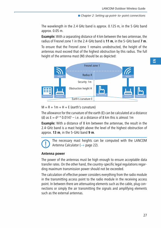
To ensure that the Fresnel zone 1 remains unobstructed, the height of theantennas must exceed that of the highest obstruction by this radius. The fullheight of the antenna mast (M) should be as depicted:
M = R + 1m + H + E (earth's curvature)
The allowance for the curvature of the earth (E) can be calculated at a distance(d) as E = d² * 0.0147 – i.e. at a distance of 8 km this is almost 1m
Example: With a distance of 8 km between the antennae, the result in the2.4-GHz band is a mast height above the level of the highest obstruction ofapprox. 13 m, in the 5-GHz band 9 m.
The necessary mast heights can be computed with the LANCOMAntenna Calculator (→ page 22).
Antenna power
The power of the antennas must be high enough to ensure acceptable datatransfer rates. On the other hand, the country-specific legal regulations regar-ding maximum transmission power should not be exceeded.
The calculation of effective power considers everything from the radio modulein the transmitting access point to the radio module in the receiving accesspoint. In between there are attenuating elements such as the cable, plug con-nections or simply the air transmitting the signals and amplifying elementssuch as the external antennas.
WLAN Router
ANTENNA
ADMINISTRATION WLAN Router
ANTENNA
PRODUCTIONOBSTRUCTION
Fresnel zone 1
Radius R
Security: 1m
Obstruction height H
Earth's curvature E
LANCOM Outdoor Wireless Guide
� Chapter 2: Setting up point- to- point connections
EN
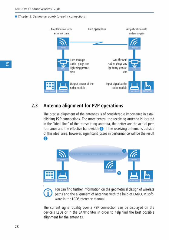
2.3 Antenna alignment for P2P operations
The precise alignment of the antennas is of considerable importance in esta-blishing P2P connections. The more central the receiving antenna is locatedin the "ideal line" of the transmitting antenna, the better are the actual per-formance and the effective bandwidth �. If the receiving antenna is outsideof this ideal area, however, significant losses in performance will be the result�.
You can find further information on the geometrical design of wirelesspaths and the alignment of antennas with the help of LANCOM soft-ware in the LCOSreference manual.
The current signal quality over a P2P connection can be displayed on thedevice's LEDs or in the LANmonitor in order to help find the best possiblealignment for the antennas.
WLAN Router
ANTENNA
ADMINISTRATION ACCESS POINT
ANTENNA
PRODUCTION
SA-5L SA-5L
Free-space lossAmplification with antenna gain
Output power of the radio module
Loss throughcable, plugs andlightning protec-
tion
Amplification with antenna gain
Input signal at theradio module
Loss through cable, plugs and lightning protec-tion
WLAN Router
ANTENNE
VERWALTUNG ACCESS POINT
ANTENNE
PRODUKTION
ANTENNE
�
�
28
LANCOM Outdoor Wireless Guide
� Chapter 2: Setting up point- to- point connections
EN
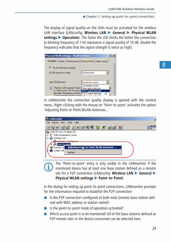
The display of signal quality on the LEDs must be activated for the wirelessLAN interface (LANconfig: Wireless LAN � General � Physical WLANsettings � Operation). The faster the LED blinks the better the connection(a blinking frequency of 1 Hz represents a signal quality of 10 dB, double thefrequency indicates that the signal strength is twice as high).
In LANmonitor the connection quality display is opened with the contextmenu. Right-clicking with the mouse on 'Point-to-point' activates the option'Adjusting Point-to-Point WLAN Antennas...'
The 'Point-to-point' entry is only visible in the LANmonitor if themonitored device has at least one base station defined as a remotesite for a P2P connection (LANconfig: Wireless LAN � General �Physical WLAN settings � Point- to-Point).
In the dialog for setting up point-to-point connections, LANmonitor promptsfor the information required to establish the P2P connection:
� Is the P2P connection configured at both ends (remote base station defi-ned with MAC address or station name)?
� Is the point-to-point mode of operation activated?
� Which access point is to be monitored? All of the base stations defined asP2P remote sites in the device concerned can be selected here.
29
LANCOM Outdoor Wireless Guide
� Chapter 2: Setting up point- to- point connections
EN
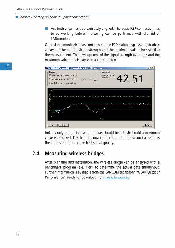
� Are both antennas approximately aligned? The basic P2P connection hasto be working before fine-tuning can be performed with the aid ofLANmonitor.
Once signal monitoring has commenced, the P2P dialog displays the absolutevalues for the current signal strength and the maximum value since startingthe measurement. The development of the signal strength over time and themaximum value are displayed in a diagram, too.
Initially only one of the two antennas should be adjusted until a maximumvalue is achieved. This first antenna is then fixed and the second antenna isthen adjusted to attain the best signal quality.
2.4 Measuring wireless bridges
After planning and installation, the wireless bridge can be analyzed with abenchmark program (e.g. iPerf) to determine the actual data throughput.Further information is available from the LANCOM techpaper "WLAN OutdoorPerformance", ready for download from www.lancom.eu.
30
LANCOM Outdoor Wireless Guide
� Chapter 3: Lightning and surge protection
EN
3 Lightning and surge protection
3.1 Where do lightning discharges come from?
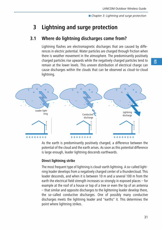
Lightning flashes are electromagnetic discharges that are caused by diffe-rences in electric potential. Water particles are charged through friction whenthere is weather movement in the atmosphere. The predominantly positivelycharged particles rise upwards while the negatively charged particles tend toremain at the lower levels. This uneven distribution of electrical charge cancause discharges within the clouds that can be observed as cloud-to-cloudlightning.
As the earth is predominantly positively charged, a difference between thepotential of the cloud and the earth arises. As soon as this potential differenceis large enough, leader lightning descends earthwards.
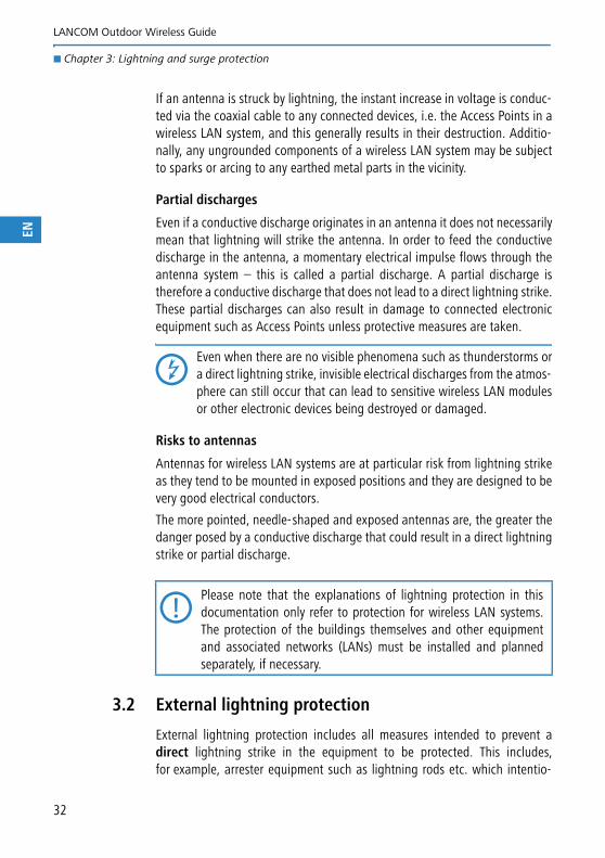
Direct lightning strike
The most frequent type of lightning is cloud-earth lightning. A so-called light-ning leader develops from a negatively charged center of a thundercloud. Thisleader descends, and when it is between 10 m and a several 100 m from theearth the electrical field strength increases so strongly in exposed places – forexample at the roof of a house or top of a tree or even the tip of an antenna– that similar and opposite discharges to the lightening leader develop there,the so-called conductive discharges. One of possibly many conductivedischarges meets the lightning leader and "earths" it. This determines thepoint where lightning strikes.
- --- --
-
---
-
+ +++
++
- --- --
-
---
-
+ +++
++
- --- --
-
---
-
+ +++
++
+ + + + + + + ++ + + + + + + + + + + + + + + ++ + + + + + + + + + + + + + + ++ + + + + + + +
Leader light-ning Conductive
discharge
Lightningdischarge
31
LANCOM Outdoor Wireless Guide
� Chapter 3: Lightning and surge protection
EN
If an antenna is struck by lightning, the instant increase in voltage is conduc-ted via the coaxial cable to any connected devices, i.e. the Access Points in awireless LAN system, and this generally results in their destruction. Additio-nally, any ungrounded components of a wireless LAN system may be subjectto sparks or arcing to any earthed metal parts in the vicinity.
Partial discharges
Even if a conductive discharge originates in an antenna it does not necessarilymean that lightning will strike the antenna. In order to feed the conductivedischarge in the antenna, a momentary electrical impulse flows through theantenna system – this is called a partial discharge. A partial discharge istherefore a conductive discharge that does not lead to a direct lightning strike.These partial discharges can also result in damage to connected electronicequipment such as Access Points unless protective measures are taken.
Even when there are no visible phenomena such as thunderstorms ora direct lightning strike, invisible electrical discharges from the atmos-phere can still occur that can lead to sensitive wireless LAN modulesor other electronic devices being destroyed or damaged.
Risks to antennas
Antennas for wireless LAN systems are at particular risk from lightning strikeas they tend to be mounted in exposed positions and they are designed to bevery good electrical conductors.
The more pointed, needle-shaped and exposed antennas are, the greater thedanger posed by a conductive discharge that could result in a direct lightningstrike or partial discharge.
3.2 External lightning protection
External lightning protection includes all measures intended to prevent adirect lightning strike in the equipment to be protected. This includes,for example, arrester equipment such as lightning rods etc. which intentio-
Please note that the explanations of lightning protection in thisdocumentation only refer to protection for wireless LAN systems.The protection of the buildings themselves and other equipmentand associated networks (LANs) must be installed and plannedseparately, if necessary.
32
LANCOM Outdoor Wireless Guide
� Chapter 3: Lightning and surge protection
EN
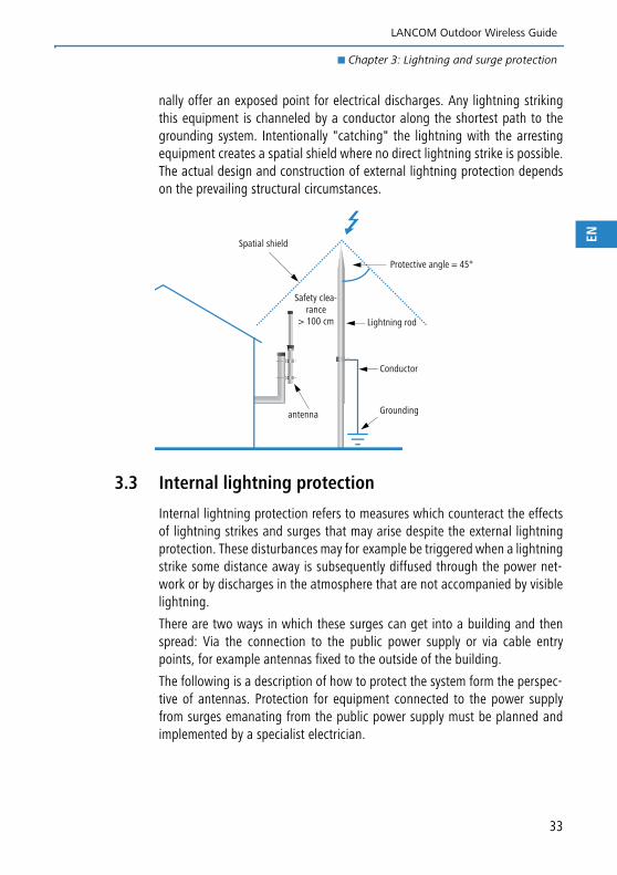
nally offer an exposed point for electrical discharges. Any lightning strikingthis equipment is channeled by a conductor along the shortest path to thegrounding system. Intentionally "catching" the lightning with the arrestingequipment creates a spatial shield where no direct lightning strike is possible.The actual design and construction of external lightning protection dependson the prevailing structural circumstances.
3.3 Internal lightning protection
Internal lightning protection refers to measures which counteract the effectsof lightning strikes and surges that may arise despite the external lightningprotection. These disturbances may for example be triggered when a lightningstrike some distance away is subsequently diffused through the power net-work or by discharges in the atmosphere that are not accompanied by visiblelightning.
There are two ways in which these surges can get into a building and thenspread: Via the connection to the public power supply or via cable entrypoints, for example antennas fixed to the outside of the building.
The following is a description of how to protect the system form the perspec-tive of antennas. Protection for equipment connected to the power supplyfrom surges emanating from the public power supply must be planned andimplemented by a specialist electrician.
Protective angle = 45°
Safety clea-rance
> 100 cm
Spatial shield
antenna
Lightning rod
Conductor
Grounding
33
LANCOM Outdoor Wireless Guide
� Chapter 3: Lightning and surge protection
EN
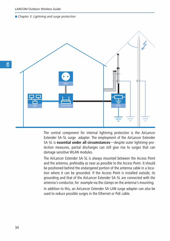
The central component for internal lightning protection is the AirLancerExtender SA-5L surge adapter. The employment of the AirLancer ExtenderSA-5L is essential under all circumstances—despite outer lightning-pro-tection measures, partial discharges can still give rise to surges that candamage sensitive WLAN modules.
The AirLancer Extender SA-5L is always mounted between the Access Pointand the antenna, preferably as near as possible to the Access Point. It shouldbe positioned behind the endangered portion of the antenna cable in a loca-tion where it can be grounded. If the Access Point is installed outside, itsgrounding and that of the AirLancer Extender SA-5L are connected with theantenna's conductor, for example via the clamps on the antenna's mounting.
In addition to this, an AirLancer Extender SA-LAN surge adapter can also beused to reduce possible surges in the Ethernet or PoE cable.
ACCESS POINT SA-5LLAN
230 V
34
LANCOM Outdoor Wireless Guide
� Chapter 3: Lightning and surge protection
EN
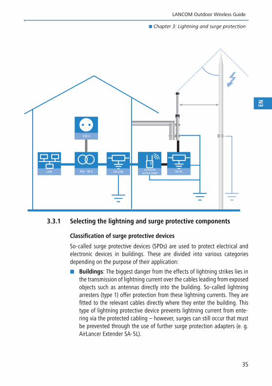
3.3.1 Selecting the lightning and surge protective components
Classification of surge protective devices
So-called surge protective devices (SPDs) are used to protect electrical andelectronic devices in buildings. These are divided into various categoriesdepending on the purpose of their application:
� Buildings: The biggest danger from the effects of lightning strikes lies inthe transmission of lightning current over the cables leading from exposedobjects such as antennas directly into the building. So-called lightningarresters (type 1) offer protection from these lightning currents. They arefitted to the relevant cables directly where they enter the building. Thistype of lightning protective device prevents lightning current from ente-ring via the protected cabling – however, surges can still occur that mustbe prevented through the use of further surge protection adapters (e. g.AirLancer Extender SA-5L).
LAN PoE - 48 V SA-5L
230 V
SA-LANOUTDOOR
ACCESS POINT
35
LANCOM Outdoor Wireless Guide
� Chapter 3: Lightning and surge protection
EN
� Power supply: Surges can also find their way into the building via thepower supply and thereby endanger electronic equipment. Surge arresters(type 2) can be used to protect against such surges. They work by reducingthe voltage peaks to a sufficiently low level. These type 2 adapters are fit-ted for example in the electrical cabinet.
� Devices: The final link in the surge protective chain is the protection ofthe devices themselves. For this, type 3 surge protective devices are used,for example in the form of power socket adapters. This type of SPD worksby lowering any surges that may occur to a level that is not dangerous forhighly sensitive equipment.
The assessment of risk and the resulting design of a suitable lightning protec-tion system is always dependent on local conditions (for example the fre-quency with which lightning strikes are to be expected) and ideally needs tobe carried out by trained experts.
The following considerations are intended to assist with planning the compo-nents to use:
External lightning protection
� Lightning rod
� When? Required if the antenna or any other element of the wirelessLAN system is mounted in an exposed position.
� Where? At least 50 cm safety clearance to the antenna or other con-ductive element of the wireless LAN system, and preferably more than100 cm.
� Conductor? Grounding via potential equalization line (PEL, 16 mm²Cu) is always required.
If the safety clearance is less than 100 cm the grounding of the light-ning rod must be connected with the grounding of the antenna.
� Antenna potential equalization
� Separate conductor: Via separate potential equalization line (PEL,16 mm² Cu) if there is no lightning rod present (antenna not installedin an exposed position).
Please note that in addition to implementing lightning protection for wireless LANsystems, protection must be separately planned and installed for the building itselfand for other equipment.
36
LANCOM Outdoor Wireless Guide
� Chapter 3: Lightning and surge protection
EN
� Separate conductor: Via separate potential equalization cable(16 mm² Cu) if the safety clearance between the the lightning and theantenna is more than 100 cm.
� Via lightning rod conductor: Grounding via the existing potentialequalization cable of the lightning rod when the safety clearance bet-ween lightning rod and antenna or other conductive element of thewireless LAN system is more than 50 cm but less than 100 cm.
Internal lightning protection
� Surge-protectionadapter AirLancer Extender SA-LAN
� When? Depends on the individual risk and protection requirements ofthe devices and cabling in the LAN, e.g. the outdoor equipment withintegrated antennas.
� Where? As near as possible to the Access Point's ETH connector.
� Conductor? Potential equalization via the building's grounding sys-tem using a PE line (protective earth – 1.5 mm² Cu).
3.3.2 Example applications
Depending on where the Access Points, antennas and lightning rods are posi-tioned there are numerous combinations of lightning and surge protectiveequipment. The following illustrations show some sample scenarios that are
� Surge-protection adapter AirLancer Extender SA-5L
� When? Always required. Also protects against partial dischargesthat can damage sensitive wireless LAN modules when there is nodirect lightningstrike.
� Where? Position as near as possible to antenna connector on theAccess Point.
� Conductor? Potential equalization via the building's groundingsystem using a PE line (protective earth – 1.5 mm² Cu).
LANCOM Systems will only fulfill its warranty obligations whenWLAN devices are operated in combination with an AirLancerExtender SA-5L surge protection adapter. This lightning protectionis explicitly designed for the WLAN modules in LANCOM devices.Warranty obligations shall not be fulfilled if different surge-protec-tion adapters are used.
37
LANCOM Outdoor Wireless Guide
� Chapter 3: Lightning and surge protection
EN
frequently found in practice. With this knowledge you will be able to put toge-ther the components required for other constellations.
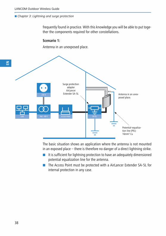
Scenario 1:
Antenna in an unexposed place.
The basic situation shows an application where the antenna is not mountedin an exposed place – there is therefore no danger of a direct lightning strike.
� It is sufficient for lightning protection to have an adequately dimensionedpotential equalization line for the antenna.
� The Access Point must be protected with a AirLancer Extender SA-5L forinternal protection in any case.
LAN PoE - 48 V ACCESS POINT SA-5L
230 V Antenna in an unex-posed place.
Potential-equaliza-tion line (PEL)16mm² Cu
Surge protection adapter
AirLancer Extender SA-5L
38
LANCOM Outdoor Wireless Guide
� Chapter 3: Lightning and surge protection
EN
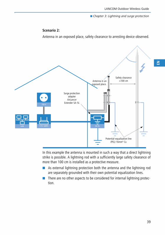
Scenario 2:
Antenna in an exposed place, safety clearance to arresting device observed.
In this example the antenna is mounted in such a way that a direct lightningstrike is possible. A lightning rod with a sufficiently large safety clearance ofmore than 100 cm is installed as a protective measure.
� As external lightning protection both the antenna and the lightning rodare separately grounded with their own potential equalization lines.
� There are no other aspects to be considered for internal lightning protec-tion.
LAN 1751 UMTS SA-5L
230 V
Antenna in anexposed place.
Potential-equalization line (PEL) 16mm² Cu
Safety clearance >100 cm
Surge protection adapter
AirLancer Extender SA-5L
39
LANCOM Outdoor Wireless Guide
� Chapter 3: Lightning and surge protection
EN
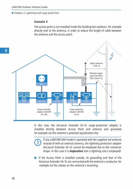
Scenario 3:
The access point is not installed inside the building but outdoors, for exampledirectly next to the antenna, in order to reduce the length of cable betweenthe antenna and the access point.
In this case, the AirLancer Extender SA-5L surge-protection adapter isinstalled directly between Access Point and antenna and groundedfor example via the antenna's potential equalization line.
If any LANCOM OAP model is operated with the supplied rod antennainstead of with an external antenna, the lightning protection adapterAirLancer Extender SA-5L cannot be employed due to the connectorshape. In this case it is imperative that a lightning rod is employed!
� If the Access Point is installed outside, its grounding and that of theAirLancer Extender SA-5L are connected with the antenna's conductor, forexample via the clamps on the antenna's mounting.
LAN PoE - 48 V SA-5L
230 V
SA-LANOUTDOOR
ACCESS POINT
Surge-protection adapter LANCOM
SA-5L
Potential-equali-zation line (PEL) (PEL) 16mm² Cu
Safety clearance >100 cm
Surge-protection adapter LANCOM
SA-LAN
40
LANCOM Outdoor Wireless Guide
� Chapter 3: Lightning and surge protection
EN
� The AirLancer Extender SA-5L can be fixed directly to the antenna socketwith the aid of a short adapter (gender changer), depending on the modelof the Access Point.
41
LANCOM Outdoor Wireless Guide
� Chapter 4: Installation
EN
4 Installation
4.1 Safety advice
Do not mount Access Points or antennas in weather conditions whenlightning may be expected. Similarly, refrain from connecting or disconnecting cablesduring weather of this type.The components of a wireless LAN can be subject to variations in elec-trical charge even in normal weather conditions. Please perform allwork with the utmost care.
Access Points, antennas and mounting equipment such as mastsintended for outdoor operation must be grounded. Never work withAccess Points and antennas if you are not certain of proper ground.Please seek advice from a qualified electrician to clarify this issue.
The installation and mounting of Access Points and antennas should only becarried out by experienced IT personnel or trained electricians. Please observethe following notices to avoid accidents:
� Never carry out work of this type alone, but with a minimum of two peo-ple. This ensures that help can be quicker to hand if an accident occursdespite all safety precautions.
� Only use ladders with the appropriate insulation.
� Do not work in strong winds or rain. If necessary use a safety harness.
� Wear suitable working clothing, such as close-fitting clothing and safetyshoes with non-slip soles.
� If components of the antenna or mountings should be dropped, let themfall and do not attempt to catch them. Falling antennas, masts or cablesmay come into contact with live contacts and cause electric shock.
� The mounting location should be easily accessible in the interests of futuremaintenance work or for checking cable connections.
� Before commencing with mounting, ensure that you have all the neces-sary tools and accessory parts. Similarly, ensure that any openingsrequired for the entry of the coaxial or Ethernet cable into the building arealready available.
42
LANCOM Outdoor Wireless Guide
� Chapter 4: Installation
EN
In the interests of your own safety, antennas, masts and the groun-ding system should only be installed by experienced electricians whoare familiar with local conditions and any legal regulations whichapply. Furthermore, please observe the notices in section → 'Surgeand lightning protection' and ensure that the grounding systemmeets requirements.
4.2 Mounting the Access Points
The method for mounting the Access Point depends on the model's design.This section presents the various mounting types as illustrated by examples.Please refer to the documentation of the relevant Access Point for more pre-cise instructions.
4.2.1 Selecting the location for mounting
Before mounting any Access Points a suitable location should be found thatmeets the following conditions:
� The Access Points and antennas should not be covered up in order toavoid interference or overheating etc. during transmission and reception.
� Choose a location that is as close as possible to the necessary connectionssuch as LAN interfaces or power sockets.
� Position the Access Points as close as possible to the antennas. The lengthof the coaxial cable between Access Point and antenna has a considerableinfluence on the attenuation in the wireless LAN system as a whole, thusimpacting the available range and data rates, for example.
� Maximum separation is also important for an Access Point and PoE injec-tor. Some Access Points have for example an increased power require-
Please observe the following advice during installation:
Access Points installed outside may only be protected from directlightning strikes with a lightning rod with a safety clearance ofmore than 100 cm.
Access Points installed outside must be grounded with an adequa-tely dimensioned potential equalization line (PEL) with a cross-sec-tion of at least 16 mm² CU.
For the protection of sensitive wireless LAN modules, it is impera-tive to use an AirLancer Extender SA-5L surge-protection device.
43
LANCOM Outdoor Wireless Guide
� Chapter 4: Installation
EN
ment that can only be supplied over a specific length of Ethernet cable.Detailed advice is available in the documentation for the Access Point orthe PoE injector.
� Locations where components are mounted outdoors should be as close aspossible to the point where the coaxial or Ethernet cables enter the buil-ding. Excessive stretches of outdoor cabling are exposed to increaseddanger from the effects of lightning.
� Avoid locations that are very dusty.
� In outdoor areas, avoid locations that are close to exposed metallic con-ductors such as guttering, downpipes, etc.
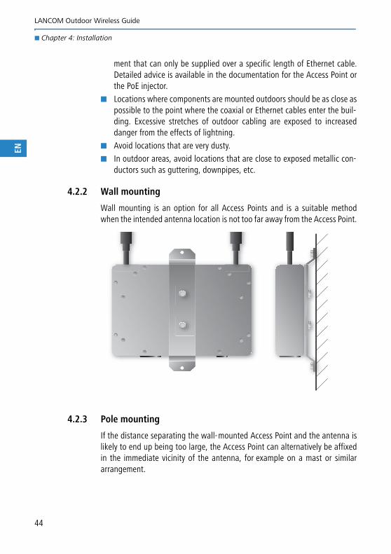
4.2.2 Wall mounting
Wall mounting is an option for all Access Points and is a suitable methodwhen the intended antenna location is not too far away from the Access Point.
4.2.3 Pole mounting
If the distance separating the wall-mounted Access Point and the antenna islikely to end up being too large, the Access Point can alternatively be affixedin the immediate vicinity of the antenna, for example on a mast or similararrangement.
44
LANCOM Outdoor Wireless Guide
� Chapter 4: Installation
EN
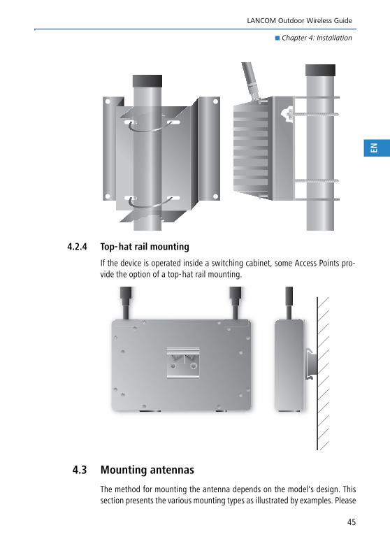
4.2.4 Top-hat rail mounting
If the device is operated inside a switching cabinet, some Access Points pro-vide the option of a top-hat rail mounting.
4.3 Mounting antennas
The method for mounting the antenna depends on the model's design. Thissection presents the various mounting types as illustrated by examples. Please
45
LANCOM Outdoor Wireless Guide
� Chapter 4: Installation
EN
refer to the documentation of the relevant antenna for more precise instruc-tions.
4.3.1 Selecting the location for mounting
Before mounting any antennas a suitable location should be found that meetsthe following conditions:
� Mount the antennas in a place offering a good line of sight for transmit-ting data to mobile wireless LAN clients or remote P2P stations. You willfind advice on antenna alignment in P2P mode in Chapter → 'Point-to-point connections (P2P mode)'.
� Mount antennas as near as possible to the Access Points. The length ofthe coaxial cable between Access Point and antenna has a considerableinfluence on the attenuation in the wireless LAN system as a whole, thusimpacting for example the available range and possible data rates.
� Locations where components are mounted outdoors should be as close aspossible to the point where the coaxial or Ethernet cables enter the buil-ding. Excessive stretches of outdoor cabling are exposed to increaseddanger from the effects of lightning.
� In outdoor areas, avoid locations that are close to exposed metallic con-ductors such as guttering, downpipes, etc.
4.3.2 Wall mounting
Permanent mounting can take place directly on a wall or with the adjustableswivel fixture.
Please observe the following advice during installation:
Antennas mounted outside in an exposed location where directlightning strikes can occur must be protected by a lightning rodinstalled at a distance of at least 100 cm.
Antennas mounted outside must be grounded with an adequatelydimensioned potential equalization line (PEL) with a cross-sectionof at least 16 mm² Cu.
For the protection of sensitive wireless LAN modules, it is impera-tive to use an AirLancer Extender SA-5L surge-protection device.
46
LANCOM Outdoor Wireless Guide
� Chapter 4: Installation
EN
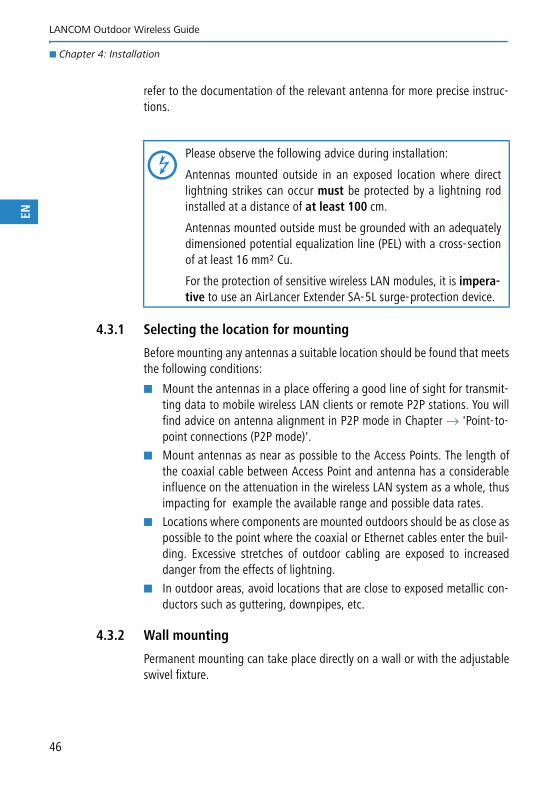
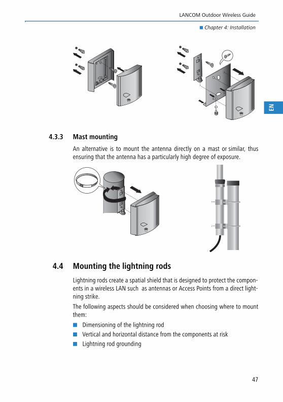
4.3.3 Mast mounting
An alternative is to mount the antenna directly on a mast or similar, thusensuring that the antenna has a particularly high degree of exposure.
4.4 Mounting the lightning rods
Lightning rods create a spatial shield that is designed to protect the compon-ents in a wireless LAN such as antennas or Access Points from a direct light-ning strike.
The following aspects should be considered when choosing where to mountthem:
� Dimensioning of the lightning rod
� Vertical and horizontal distance from the components at risk
� Lightning rod grounding
47
LANCOM Outdoor Wireless Guide
� Chapter 4: Installation
EN
The dimensioning, installation and grounding of the lightning rodsshould only be performed by trained electricians.
4.4.1 Dimensioning of the lightning rod
The lightning rod must be able to conduct the complete charge of a lightningstrike. For this reason it is important to select rods made from highly conduc-tive metals, for example copper alloys or steel. It is important to select rodswith a cross-section that allows the lightning charge to be conducted withoutbeing damaged, in general a diameter of between 10 and 16 mm.
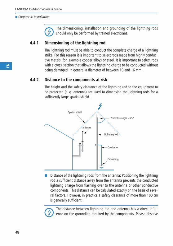
4.4.2 Distance to the components at risk
The height and the safety clearance of the lightning rod to the equipment tobe protected (e. g. antenna) are used to dimension the lightning rods for asufficiently large spatial shield.
� Distance of the lightning rods from the antenna: Positioning the lightningrod a sufficient distance away from the antenna prevents the conductedlightning charge from flashing over to the antenna or other conductivecomponents. This distance can be calculated exactly on the basis of seve-ral factors. However, in practice a safety clearance of more than 100 cmis generally sufficient.
The distance between lightning rod and antenna has a direct influ-ence on the grounding required by the components. Please observe
Protective angle = 45°
Spatial shield
antenna
Lightning rod
Conductor
Grounding
48
LANCOM Outdoor Wireless Guide
� Chapter 4: Installation
EN
the advice about grounding the lightning rods and grounding theantennas and Access Points.
� Lightning rod height: The lightning rod must be high enough to ensurethat the equipment that is to be protected such as antennas are within thespatial shield. Besides the exact rolling sphere method used to determinethe areas at risk there is the simpler protective angle method which canbe used to approximate the spatial shield formed by a lightning rod. Thismethod assumes an area of 45° under the lightning rod to be safe fromdirect lightning strikes.
4.4.3 Lightning charge conduction (grounding)
Lightning rods must always be grounded with a separate, adequately dimen-sioned potential equalization line (PEL) with a cross-section of at least16 mm² Cu. The connection to the grounding system must be made using theshortest path.
If the lightning rod and antenna are mounted together on the samemast and the distance to the antenna is more than 100 cm, the light-ning rod must be adequately insulated from the mast since in this casethe lightning rod and the antenna must be separately grounded.
49
LANCOM Outdoor Wireless Guide
� Chapter 5: Appendix
EN
5 Appendix
5.1 Antenna gain, EIRP and antenna radiation characte-ristics
In order to be able to make a statement on the suitability of an antenna forany particular application, the technical specifications state data such asantenna gain, radiated power (EIRP), angle of beam spread, and the radiationcharacteristics of the antenna.
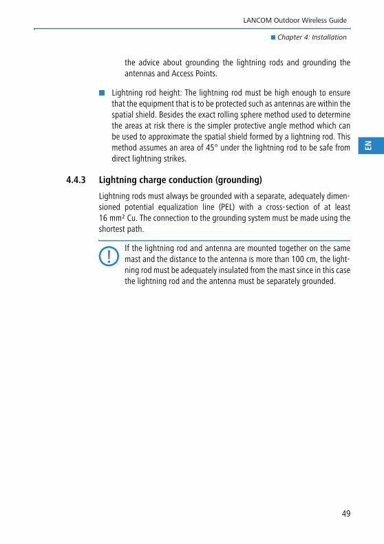
In practice, the different antenna models have beams that are focused intosectors of varying size. These geometrical radiation characteristics areexpressed by the equivalent isotropic radiated power, or EIRP. To determineEIRP, an antenna is viewed theoretically as an isotropic or spherical radiatorthat emits radiation of the same power in all directions. The EIRP is theamount of power that would have to be emitted by an isotropic antenna toproduce the peak power density observed in the direction of maximumantenna gain.
The power fed into the antenna is focused, and thus amplified, into a mainbeam direction. This amplification is referred to as "gain". The greater thefocussing, the greater is the antenna gain.
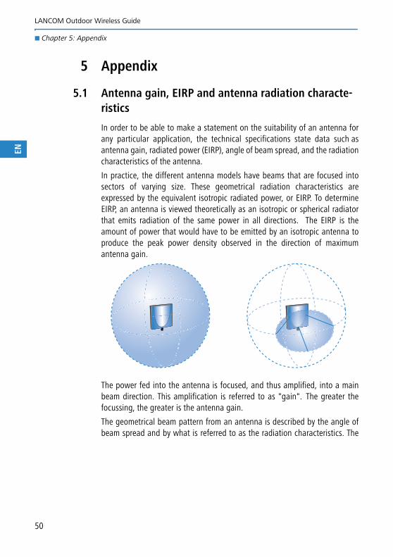
The geometrical beam pattern from an antenna is described by the angle ofbeam spread and by what is referred to as the radiation characteristics. The
50
LANCOM Outdoor Wireless Guide
� Chapter 5: Appendix
EN
radiation characteristics represent the spatial distribution of the radiatedpower.
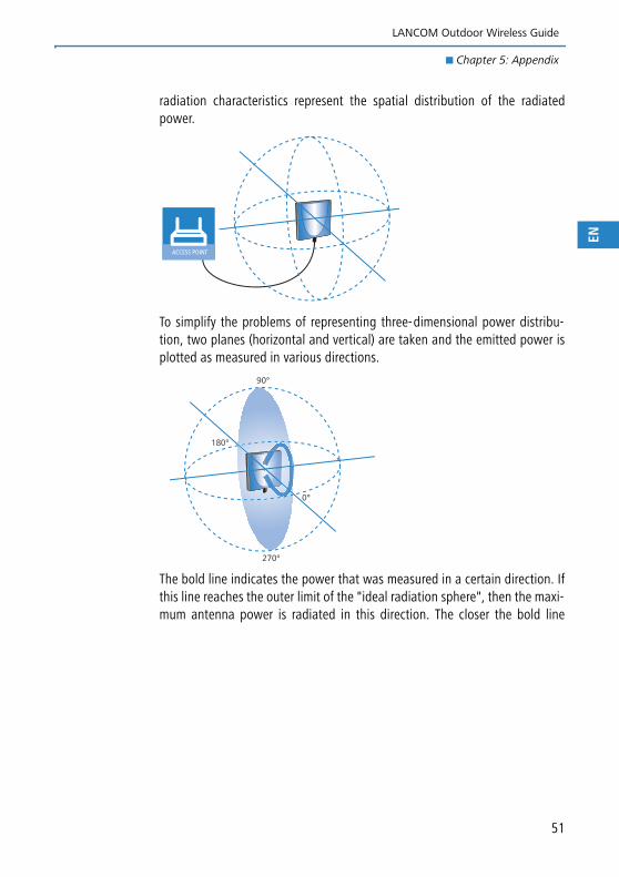
To simplify the problems of representing three-dimensional power distribu-tion, two planes (horizontal and vertical) are taken and the emitted power isplotted as measured in various directions.
The bold line indicates the power that was measured in a certain direction. Ifthis line reaches the outer limit of the "ideal radiation sphere", then the maxi-mum antenna power is radiated in this direction. The closer the bold line
ACCESS POINT
0°
180°
90°
270°
51
LANCOM Outdoor Wireless Guide
� Chapter 5: Appendix
EN
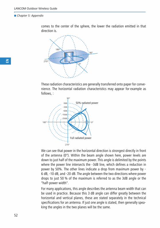
comes to the center of the sphere, the lower the radiation emitted in thatdirection is.
These radiation characteristics are generally transferred onto paper for conve-nience. The horizontal radiation characteristics may appear for example asfollows, :
We can see that power in the horizontal direction is strongest directly in frontof the antenna (0°). Within the beam angle shown here, power levels aredown to just half of the maximum power. This angle is delimited by the pointswhere the power line intersects the -3dB line, which defines a reduction inpower by 50%. The other lines indicate a drop from maximum power by -6 dB, -10 dB, and -20 dB. The angle between the two directions where powerdrops to just 50 % of the maximum is referred to as the 3dB angle or the"half-power width".
For many applications, this angle describes the antenna beam width that canbe used in practice. Because this 3 dB angle can differ greatly between thehorizontal and vertical planes, these are stated separately in the technicalspecifications for an antenna. If just one angle is stated, then generally spea-king the angles in the two planes will be the same.
0°
180°
90°
270°
0db
-3db
-6db
.-10db
-20db
0°180°
90°
270°
Full radiated power
50% radiated power
52
LANCOM Outdoor Wireless Guide
� Chapter 5: Appendix
EN
The radiation characteristics do not indicate absolute transmissionpower or transmission range. It merely serves to indicate the percen-tage of maximum power that is emitted in any given direction.
Example applications of various wireless LAN antennas
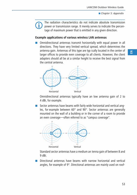
� Omnidirectional antennas transmit horizontally with equal power in alldirections. They have very limited vertical spread, which determines theantenna gain. Antennas of this type are typ ically located in the center oflarger offices to provide even coverage to all clients. However, the clientadapters should all be at a similar height to receive the best signal fromthe central antenna.
Omnidirectional antennas typically have an low antenna gain of 2 to4 dBi, for example.
� Sector antennas have beams with fairly wide horizontal and vertical ang-les, for example between 60° and 90°. Sector antennas are generallymounted on the wall of a building or in the corner of a room to providean even coverage—often referred to as "campus coverage".
Standard sector antennas have a medium an tenna gain of between 8 and9 dBi.
� Directional antennas have beams with narrow horizontal and verticalangles, for example of 9°. Directional antennas are mainly used on roof-
0°180°
90°
270°
0°180°
90°
270°
VerticalHorizontal
0°180°
90°
270°
0°180°
90°
270°
VerticalHorizontal
53
LANCOM Outdoor Wireless Guide
� Chapter 5: Appendix
EN
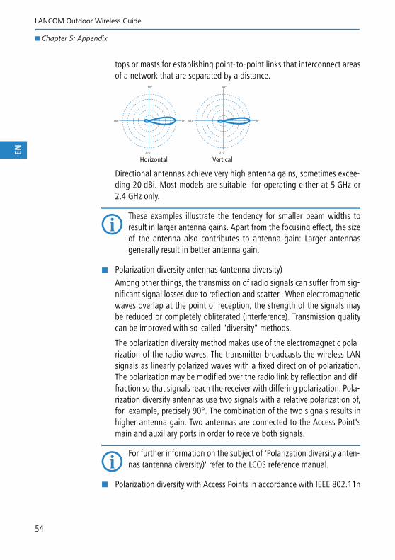
tops or masts for establishing point-to-point links that interconnect areasof a network that are separated by a distance.
Directional antennas achieve very high antenna gains, sometimes excee-ding 20 dBi. Most models are suitable for operating either at 5 GHz or2.4 GHz only.
These examples illustrate the tendency for smaller beam widths toresult in larger antenna gains. Apart from the focusing effect, the sizeof the antenna also contributes to antenna gain: Larger antennasgenerally result in better antenna gain.
� Polarization diversity antennas (antenna diversity)
Among other things, the transmission of radio signals can suffer from sig-nificant signal losses due to reflection and scatter . When electromagneticwaves overlap at the point of reception, the strength of the signals maybe reduced or completely obliterated (interference). Transmission qualitycan be improved with so-called "diversity" methods.
The polarization diversity method makes use of the electromagnetic pola-rization of the radio waves. The transmitter broadcasts the wireless LANsignals as linearly polarized waves with a fixed direction of polarization.The polarization may be modified over the radio link by reflection and dif-fraction so that signals reach the receiver with differing polarization. Pola-rization diversity antennas use two signals with a relative polarization of,for example, precisely 90°. The combination of the two signals results inhigher antenna gain. Two antennas are connected to the Access Point'smain and auxiliary ports in order to receive both signals.
For further information on the subject of 'Polarization diversity anten-nas (antenna diversity)' refer to the LCOS reference manual.
� Polarization diversity with Access Points in accordance with IEEE 802.11n
0°180°
90°
270°
0°180°
90°
270°
VerticalHorizontal
54
LANCOM Outdoor Wireless Guide
� Chapter 5: Appendix
EN
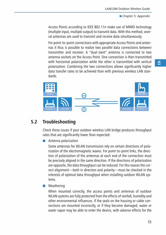
Access Points according to IEEE 802.11n make use of MIMO technology(multiple input, multiple output) to transmit data. With this method, seve-ral antennas are used to transmit and receive data simultaneously.
For point-to-point connections with appropriate Access Points and anten-nas it thus is possible to realize two parallel data connections betweentransmitter and receiver. A "dual-slant" antenna is connected to twoantenna sockets on the Access Point. One connection is then transmittedwith horizontal polarization while the other is transmitted with verticalpolarization. Combining the two connections allows significantly higherdata transfer rates to be achieved than with previous wireless LAN stan-dards.
5.2 Troubleshooting
Check these issues if your outdoor wireless LAN bridge produces throughputrates that are significantly lower than expected:
� Antenna polarization
Some antennas for WLAN transmission rely on certain directions of pola-rization of the electromagnetic waves. For point-to-point links, the direc-tion of polarization of the antennas at each end of the connection mustbe precisely aligned in the same direction. If the directions of polarizationare opposite, the data throughput can be reduced. For this reason the cor-rect alignment—both in direction and polarity—must be checked in theinterests of optimal data throughput when installing outdoor WLAN sys-tems.
� Weathering
When mounted correctly, the access points and antennas of outdoorWLAN systems are fully protected from the effects of rainfall, humidity andother environmental influences. If the seals on the housing or cable con-nections are mounted incorrectly, or if they become damaged, water orwater vapor may be able to enter the device, with adverse effects for the
WLAN 802.11n DUAL-SLANT
ZENTRALE
WLAN 802.11nDUAL-SLANT
INDUSTRIE
55
LANCOM Outdoor Wireless Guide
� Chapter 5: Appendix
EN
56
electronic components. If you experience sudden variations in datathroughput over the WLAN bridge, check the cabling and seals fordamage.
� Free line of sight and unobstructed Fresnel zones
Maximum performance requires not only a free line of sight but also aminimum separation between the line of sight and the ground or otherobstructions. The LANCOM Antenna Calculator computes the necessarymast heights for obstruction-free Fresnel zones.
� antenna cable
To optimize performance, ensure that you use a minimum length ofantenna cable with the lowest possible attenuation values.
� DFS channel selection
Check if vacant channels have been detected by the access point (LCOSmenu tree under Status/WLAN/Channel scan results).
� 40-MHz mode
To optimize performance of 802.11n access points, a neighboring channelmust be available for channel bundling. The LCOS menu tree informs youwhether an "extension channel" is available under "Status/WLAN/Radios".
� Distance settings
For longer-range wireless links to function properly, the range betweenthe two antennas has to be specified (rounded up to the nearest kilome-ter). This allows the system's internal timing values to be adjusted accor-dingly.
� General diagnosis
Packet transmission statistics can be inspected under Status/WLAN/Packets and status/WLAN/Errors. It is normal for WLANs to produce a cer-tain proportion of transmission errors.
However, high values may well indicate an environment with strong inter-ference.
Check the following values for an indication of the signal/noise ratio andfor detecting rogue APs: Status/WLAN/Channel scan results, Status/WLAN/WLAN parameters and Status/WLAN/Competing networks.
If error rates are 100%, the most probable cause is a value for distancethat is too low (see section above)
LANCOM Outdoor Wireless Guide
� Index
EN
IndexNumerics2.4-GHz band
Advantages 15Disadvantages 15
5-GHz band 17, 19Advantages 15Disadvantages 15
AAccess point 11Angle of beam spread 50Antenna Calculator 22, 23, 26, 27, 56Antenna diversity 13, 54Antenna gain 50Antenna power 27
BBFWA 17
CCampus coverage 7
DData communication to mobile objects 8DFS 15, 16, 19Directional antenna 13, 53Download 4Dynamic Frequency Selection 16
EEIRP 50Equivalent isotropic radiated power 50
FFirmware 4Fresnel zone 26
GGain 50
HHotspot 8
IIEEE 802.11a 12IEEE 802.11b 12IEEE 802.11g 12IEEE 802.11n 12Industrial applications 8Information symbols 4Isotropic radiator 50
LLightning protection
Designing the lightning protection sys-tem 35
External lightning protection 32Internal lightning protection 33Lightning current arresters 32Lightning rods 32Surge-protection adapter SA-5L 37,
38, 39, 40Lower band 19
MMiddle band 20Mounting access points
Pole mounting 44Top-hat rail mounting 45Wall mounting 44
Mounting antennasPole mounting 47Wall mounting 46
OOmnidirectional antenna 13, 53
PPoE 12PoE Injector 12Point-to-multipoint 9Point-to-point 9, 21Polarization diversity 14, 54
57
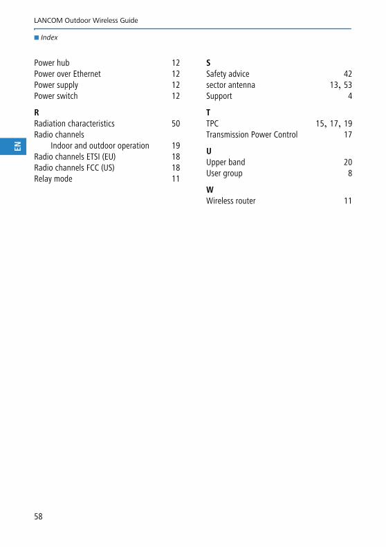
LANCOM Outdoor Wireless Guide
� Index
EN
Power hub 12Power over Ethernet 12Power supply 12Power switch 12
RRadiation characteristics 50Radio channels
Indoor and outdoor operation 19Radio channels ETSI (EU) 18Radio channels FCC (US) 18Relay mode 11
SSafety advice 42sector antenna 13, 53Support 4
TTPC 15, 17, 19Transmission Power Control 17
UUpper band 20User group 8
WWireless router 11
58

LANCOM Outdoor Wireless Guide
� Index
EN
59