lagari 2018 technical design paper for auvsi … · 2.7. air delivery ... lagari uav team technical...
TRANSCRIPT

LAGARI 2018
Technical Design Paper for AUVSI Student UAS
Competition
Yildiz Technical University
Faculty of Mechanical Engineering
Mechatronics Engineering Department
Abstract
This paper presents the design and tests processes of the ZD-01 Mini UAV for the AUVSI Student UAS
Competition 2018. Lagari UAV Team has been founded at Yildiz Technical University in 2013. In the past years,
Lagari UAV Team created multiple innovative aeronautical & aviation projects and obtained various awards. This
year will be the second year in the AUVSI SUAS competition for the team. Lagari UAV Team consists of
undergraduate students from the department of Mechatronics Engineering of Yildiz Technical University. ZD-01 was
designed, manufactured, developed and tested by Lagari UAV Team. The aircraft was manufactured with using
advanced composite technologies to provide maximum reliability and safety during the flight. The avionics were
integrated to the ZD-01 to complete all missions on the competition autonomously. Lagari UAV Team realized that
the future of UAS is guidance, control and navigation systems. With this goal, the team efforts to develop the UAS
with high performance and hi-tech. The system has capabilities such as high-performance image processing,
customized user interface, long distance wireless communication, advanced composite manufacturing based on Ansys
CFD analysis and customized algorithms for ODCL, Obstacle Avoidance and Air Delivery tasks.

Lagari UAV Team Technical Design Paper - 2018 2/15
Contents
1. System Engineering Approach .......................................................................................................................... 3
1.1. Mission Requirements Analysis ................................................................................................................... 3
1.2. Design Rationale .......................................................................................................................................... 3
2. System Design ...................................................................................................................................................... 4
2.1. Aircraft ......................................................................................................................................................... 4 2.1.1. Airframe and Surfaces ......................................................................................................................... 4 2.1.2. Aerodynamics ...................................................................................................................................... 5 2.1.3. Propulsion and Power System ............................................................................................................. 7
2.2. Autopilot ...................................................................................................................................................... 7
2.3. Obstacle Avoidance ..................................................................................................................................... 8
2.4. Imaging System ............................................................................................................................................ 9 2.4.1. Camera ................................................................................................................................................ 9 2.4.2. Gimbal ............................................................................................................................................... 10
2.5. Object Detection, Classification, Localization ........................................................................................... 10 2.5.1. Imaging Console............................................................................................................................... 10 2.5.2. Autonomous Detection ...................................................................................................................... 10 2.5.3. Manual Detection .............................................................................................................................. 11
2.6. Communication .......................................................................................................................................... 11 2.6.1. Safety Pilot Communication .............................................................................................................. 12 2.6.2. Telemetry Communication ................................................................................................................ 12 2.6.3. Payload Communication ................................................................................................................... 12
2.7. Air Delivery ............................................................................................................................................... 13 2.7.1. Design................................................................................................................................................ 13 2.7.2. Algorithm .......................................................................................................................................... 13
2.8. Cyber Security ............................................................................................................................................ 13
3. Safety, Risks & Mitigations .............................................................................................................................. 14
3.1. Development Risks & Mitigations ............................................................................................................. 14
3.2. Mission Risks & Mitigations ..................................................................................................................... 14
4. Conclusion ......................................................................................................................................................... 15
5. References .......................................................................................................................................................... 15

Lagari UAV Team Technical Design Paper - 2018 3/15
1. System Engineering Approach
1.1. Mission Requirements Analysis
Lagari designed and developed ZD-01 to accomplish all of SUAS competition tasks with paying attention to rules
that based on ‘‘AUVSI 2018 Rules for SUAS Competition” document. All our work and task performance in last year
was analyzed and weaknesses were identified. To achieve success in the competition, the importance of the tasks has
been analyzed in detail. Table 1 is shown our mission strategy.
This year the team spent their time to fly autonomously, manufacture a new fuselage, develop algorithms for
image processing and obstacle avoidance. Also, we designed new avionic boxes which is shown in Figure 2 to
accomplish all tasks in SUAS competition.
1.2. Design Rationale
Lagari will participate in the AUVSI SUAS Competition for the second time with nine undergraduate students.
In the entire design and development process of ZD-01; all equipment was selected to maximize the task performance
considering the team’s budget, capability and past years’ experience. Since budget is an important factor that limits
us during the creation of the system, the team needs sponsors throughout the pre-competition process.
This year started with analyzing the system’s defects of last year’s UAV, Huma. The aim of the team was to
eliminate the problems by improving the parameters that negatively affect our performance. Identified main problems
are shown below:
• The fuselage caused too much drag and had non-essential space.
• The gimbal system was on the outside of the fuselage thus the camera was the first component to be damaged
by any crash during landing.
• Cables and components in the fuselage were disorganized and scattered. It caused delay in debugging and
solving problems.
• The mechanism of the air drop was not sufficient. It was difficult to mount back.
• Stall speed was too high for image processing and the air drop mechanism to work properly.
Missions Explanation Executed Actions and Requirements
Timeline (10%)
• Complete this stage in minimum time
(%80)
• Needs to be completed under 45 minutes
• Avoid from take a penalty (%20)
• Simulate the assembling in every test flight
• Well-organized team
• Well-prepared checklists for every stage
Autonomous Flight
(30%)
• UAV needs to fly autonomously over
waypoints (%40)
• Refrain from safety takeovers (%10)
• Capture the waypoints as close as
possible (%50)
• Well-calibrated equipment (Air Speed,
Compass, Accelerometer)
• Investigate the log data after each flight
• Over 15 hours autonomous flight which 10
hours were in the SITL (Software in the Loop)
simulation
ODCL
(20%)
• Object characteristics must be
determined correctly (%20)
• Localization of detected object (%30)
• Correct file format while sending to the
interoperability server (%30)
• Autonomous detection (%20)
• Developing a deep-learning algorithm for
detection the objects autonomously
• A new algorithm for geo location calculation
• Autonomous JSON file converter algorithm for
communication with Interopability server
Obstacle Avoidance
(20%) • Avoid from moving (%50) and
stationary (%50) obstacles • Developing a new algorithm for obstacles
Air Delivery (10%) • Drop an object to a specified position • Well-qualified mechanic system
• Give attention to calculation
Operational
Excellence (10%)
• Professionalism, communication
between members, reaction to system
failures
• Well-defined personal responsibilities
• Usage of walkie-talkie between the GCS and
assembly team
Table 1: Mission Table

Lagari UAV Team Technical Design Paper - 2018 4/15
The team worked to find solutions to the identified
problems within the frame of possibilities. The team's
capabilities, budget and acquired experience played an
important role in bringing these solutions to light.
In the design process, utter importance was given
to the aerodynamic design of the fuselage, so it was
completely re-designed from scratch. The idea behind
it, was to produce as minimum drag as possible. Also,
the size of the fuselage was reduced dramatically.
The gimbal system has been relocated to the inside
of the fuselage within a bell glass to reduce drag and
vibration. This improvement protects the camera system
from crashes and makes the aircraft more aerodynamic.
To resolve the disorder in the fuselage, two
avionic boxes were designed. The Payload Box (PB)
contains the necessary parts for ODCL mission. The
Control Box (CB) includes the essential components
to fly manually and autonomously. Additionally,
sockets were used for practical assembling. Figure 2
illustrates the avionic boxes.
The wing area was increased to reduce the cruise
speed. Thus, the aircraft can fly slower and capture
more images from search area during the mission.
2. System Design
2.1. Aircraft
2.1.1. Airframe and Surfaces
• Fuselage
The fuselage is the most significant part of the aircraft. Since
it will house all our electronic equipment and fitting elements, more
attention was paid to its volume and strength. Different from last
year, the fuselage was designed like shape of airfoil, so it causes
less drag. Also, the volume of the fuselage was reduced by 39% and
adjusted according to the components to be used. It was aimed to
be easily accessible to all avionic boxes in the fuselage. It is
possible to achieve high strength and lightweight material by
advanced composite technology. After comparisons between other
composite materials, it was concluded that carbon fiber was the
right choice to meet our requirements. For this reason, the team
decided to manufacture by using process of composite laying on the
wooden mold with the vacuum method as shown in Figure 3.
According to the result of the strength and load analysis, an extensive lamination plan was created. The fuselage
durability was increased by using different types and amounts of carbon fiber on areas where the loading was most
expected during the flight.
Wing slots were created on the fuselage with the purpose of easily mounting the main wings. Carbon fiber pipes
were used to assembly wings and tails to the fuselage. To decrease fuselage weight and improve durability at the same
time, carbon fiber pipe was also used between the fuselage and the tail part. The tail assembly was changed in this
Figure 1: Flow diagram of decisions
Figure 3: Composite manufacturing of fuselage
Figure 2: Control Box and Payload Box

Lagari UAV Team Technical Design Paper - 2018 5/15
year because of the difficulties of detaching the tail from the fuselage. So instead of a 3D printed part, a carbon fiber
pipe that covered the tail pipe was used to connect the tail to the fuselage.
• Wings
To get more lift force, ZD-01’s wingspan was increased by 10 cm to
280 cm compared to the last years design. Wings taper off from the root to
the tip so chord length at the wing roots are 330 mm and the chord length
at the wing tips are 220 mm. Also, wing loading was reduced by increasing
the wing area 16%.
Symmetric airfoil was used for the tail part. The elevator was designed
for providing more lift during takeoff and the fin was also designed with
the purpose of improving the maneuverability of ZD-01. The dimensions
of the rudder were changed to increase its effect during the flight. The fin
and the tail part were deliberated to be detachable from the tail pipe.
XPS (Extruded polystyrene) foam was preferred as the main material
of the wing’s structure because it is cheaper than other foams and more
ductile than balsa wood. Our own cutting mechanism with hot Ni-Cr wire
was used during manufacturing process of main wings and the tail part as
shown in Figure 4. The wing was casted with carbon fiber using vacuum
method to obtain the final shape of the wings. The wings were supported
by carbon fiber pipes as spars extending into the fuselage to increase the
strength and durability. For easy transportability, wings were designed and
manufactured to be detachable from the fuselage.
• Landing Gear
ZD-01’s landing gear was designed, analyzed and
manufactured to provide the desired balance and durability. Tri-
cycle landing gear was chosen due to the advantage of take-
off/landing run and stability during taxi. The wheelbase of main
landing gear was determined to provide the necessary force
absorption during landing and stability during rotation. Landing
gear was placed with respect to load ratio. The nose and main
landing gears load ratio is 1:4.
Calculations showed that the aircraft will resist up to 25 km/h
of wind from the sides while taxing. The height of the landing gear
was reduced from last year to be more stable. Landing gear was manufactured from carbon fiber. Areas exposed to
the highest load according to ANSYS analysis (Figure 6), were supported by extra carbon fiber. Different from last
year, two layers of Kevlar were added to let it be more elastic. Also, two Rohacells were used to make it more durable.
2.1.2. Aerodynamics
While Lagari was planning their strategy for AUVSI SUAS
2018 competitions, the team aimed that the aircraft must have
better aerodynamic stability and higher maneuverability to obtain
maximum points from missions. The points that need to be
improved from last year were identified. Asymmetric Eppler 214
airfoil with high camber ratio was used for improved stall
characteristic of wings and to get more lift force at zero-degree
angle of attack (AoA). To improve maneuverability, the Aspect
Ratio (AR) was determined in accordance with the optimum AR
range of sailplane aircraft models. The tapered trapezoidal wings
platform was preferred for keeping the AR between 8-10. AR and
Figure 4: Vacuum Infusion on Wing Mold
Figure 6: Landing Gear Stress Analysis
Figure 7: XFLR5 VLM Analysis
Figure 5: Wing Loading Test

Lagari UAV Team Technical Design Paper - 2018 6/15
taper ratios are shown on Table 2. The main wings have four degrees of angle of incidence to allow us to provide
higher CL coefficient.
Because of manufacturing difficulty, the team has decided not to use dihedral angle on the wings. The most
important factors in aircraft design processes are airfoil selection, center of gravity (CG) localization, wings-tail sizing
and localization [1]. They were analyzed in low Reynolds numbers with COMSOL Multiphysics and XFLR5 CFD
analysis programs which were based on Vortex Lattice Method (Figure 7).
The optimum aerodynamic values were determined with improved analysis. This year, some dimensions and
parameters were changed so the following values were obtained:
• Cruise speed was reduced to 15 m/s and stall speed was reduced to 11 m/s.
• The wing’s CL was increased by 13 percent to 0.737 at zero-degree AoA.
• CL/CD ratio has reached 22.4 for wings and tail at zero-degree AoA.
Flaps were not found necessary on wings because of advanced aerodynamic CL/CD ratio and low stall speed
characteristics. Ailerons’ length was determined as %53 of half wingspan and width was determined as %24 of root
chord. This sizing provided to the UAV desirable maneuverability.
GENERAL CHARACTERISTICS PERFORMANCE MAIN WING
Length 1.95 m Stall Speed 21 Kts (11 m/s) Airfoil E214
Total Wingspan 2.80 m Cruise Speed 29 Kts (15 m/s) Span 2.80 m
Empty Weight 3.50 kg Max Speed 48 Kts (25 m/s) Area 0.75 m²
MTOW 9.4 kg Wing
Loading 11.2 kg/m²
Aspect
Ratio 8.9
Rate of Climb 250 m/min VERTICAL STABILIZER HORIZONTAL STABILIZER
Minimal Turn Radius 20 m Airfoil NACA 0012 Airfoil NACA 0012
Maximum Flight
Autonomously 40 minutes Span 0.30 m Span 0.40 m
Operational Range 4 km Area 0.07 m² Area 0.20 m²
Operational Ceiling 450 m Aspect Ratio 2.6 Aspect
Ratio 3.2
Table 2: General Features of ZD-01
Figure 8: Different Views of ZD-01

Lagari UAV Team Technical Design Paper - 2018 7/15
2.1.3. Propulsion and Power System
• Propulsion
Lagari decided to keep on using electrical
motor because team has good experience from
previous year. Extensive research about brushless
dc motor was carried out by the team. Result of the
research is shown in Table 3. AXI 5320/18 has better
properties than the other models in terms of propeller size
and required voltage.
• Power
There are three main power sources that consist
of Li-Po cells which is 2280 mAh and 30 C in ZD-
01. Each one of the cell can give
2280[𝑚𝐴ℎ] ∗ 30[C] = 68.4[𝐴]
to the system for instant time. Power sources and properties are shown in Table 4. In order to determine the flight
time, ground test was performed. ZD-01 was pinned to the ground when the entire system was operated, and the
current was measured. Result of the test showed that motor has drawn 18A in normal condition at %50 throttle. For
this output, flight time calculation is shown below;
6[𝑛𝑢𝑚𝑏𝑒𝑟 𝑜𝑓 𝑝𝑎𝑟𝑎𝑙𝑙𝑒𝑙 𝑢𝑛𝑖𝑡𝑠]∗2,28[𝐴ℎ]∗60[𝑐𝑜𝑛𝑣𝑒𝑟𝑡 𝑡𝑜 𝑚𝑖𝑛.]
18[𝐴] = 45[min]
2.2. Autopilot
Through last year experiences with flight controllers, it was decided to use Pixhawk 2.1 Cube as the flight
controller which is the upgraded version of Pixhawk 2.4.8 since it satisfies all subsystem requirements appropriately.
Pixhawk is responsible for all autonomous flight missions of ZD-01 while providing high accuracy, high reliability
and low risk. These following exclusive features of Pixhawk Cube 2.1 contributed to the selection process:
• A very powerful 32-bit processor with an additional fail-safe backup controller which has high accuracy and
extensive memory.
• A Unix/Linux-like programming environment, integrated multithreading and open-source powerful
development capabilities.
• It has three redundant IMUs (Inertial Measurement Units) board which is separated from the FMU (Flight
Management Unit) system.
• Peripheral units include analog and digital airspeed sensors, telemetry, rangefinder, external multi-color
LED indicators and external compasses etc.
In this year, flight control system of ZD-01 has been designed and integrated into a single Control Box System
(CBS) to simplify the cable complexity inside the aircraft and make the system more reliable. All connections between
CBS and peripheral devices were implemented according to Civil Aviation Safety Regulations (CASR). The CBS
includes Pixhawk 2.1 Cube, RFD900+ telemetry radio receiver for long range serial communication, ppm encoder,
5V regulator, hardware safety button for emergency cases, radio receiver for safety pilot and D-Sub connectors.
Additionally, autopilot system was connected with Payload Box (PB) in the aircraft via USB port. In case of any
telemetry radio link breakdown, autopilot system will connect the ground station via PB. Also, this USB connection
provides the autopilot backup power.
An open-source firmware called ArduPlane v3.8.4 has been used on Pixhawk since it has exclusive features such
as PID controller, Extended Kalman Filter(EKF), L1 Controller to tune aircraft for optimized distinctive capabilities.
So, it will contribute to execute effective autonomous take off, flight and landing during mission.
Motor
Model KV Ampere(max)/Battery Propeller
Weight
of
Model
AXI
5320/18 370 55A/6S Li-Po 18"x10" 9000 gr
AXI
5320/28 249 45A/8S Li-Po 20"x10" 8500 gr
Scorpion
4035 380 79.4 A/8S Li-Po 15"x8" 8200 gr
Table 3: Engine Comparison
Battery Connected to
6S/6P
3S/2P
Motor/Control box
Payload Box
2S/2P Servo Motors
Table 4: Power Distribution

Lagari UAV Team Technical Design Paper - 2018 8/15
PID controller is effective in autonomous flight. Thus, we executed several flight tests to tune PID parameters for
the aircraft. Also, a guidance algorithm is used for path control named L1 controller [2]. The algorithm consists of
two parts. Firstly, a reference waypoint is calculated along the trajectory to be followed. Secondly, lateral acceleration
is calculated that intercepts reference waypoint. Moreover, data such as altitude, position, velocity, which are vital for
the autonomous flight of the ZD-01, have been improved using Extended Kalman Filter (EKF) which is an optimal
estimation algorithm to reject measurements with significant error [3].
After doing many test flights in
SITL and gaining experience, the
team optimized all autonomous
functions by testing separately.
Mission Planner is used as ground
control interface to communicate with
Pixhawk via 915 MHz RFD900+
telemetry. This interface is a full-
featured software for the open source
autopilots and provide dynamic control
for autonomous flight. We made some
modification on the software since
Mission Planner is an open source
firmware. These modifications allow us
to communicate with interop server.
Also, the software was modified to
perform obstacle avoidance mission.
2.3. Obstacle Avoidance
This year, the new algorithm which based on Rapidly Exploring Random Trees (RRT) was developed. Basically,
RRT finds a route between two points, but it may select non-optimal path. So, Lagari developed Optimized Obstacle
Avoidance Algorithm (OOAA). It adds new waypoints to the original path, in the circumstances of UAV capabilities,
when a collision is calculated and send updated path to UAV. These new waypoints are offsetted 10 meters to the
obstacle’s radius due to accuracy of ZD-01’s waypoint capture radius. OOAA was tested in SITL environment and
Table 6 shows results.
Autonomous Flight Time of Flight Success Rate
Take-off 45 minutes %90
Waypoint Navigation 6 hours %95
Landing 20 minutes %70
Figure 11: Before Algorithm Detect Obstacle
Figure 9: Autopilot System Figure 10: Whole System
Table 5: Autonomous Flight Test

Lagari UAV Team Technical Design Paper - 2018 9/15
2.4. Imaging System
2.4.1. Camera
Since camera is the main component for ODCL mission, camera selection is vital. Sony A6000, which was used
last year, has high resolution but it can capture only 0.4 FPS and has low shutter speed. This year, image processing
will be provided on real-time video. Using this method, manual object detection will be more efficient by scanning
wider area. Sony FCB-IX 11 AP camera was chosen due to its lightweight, 10x optical zoom, live photo feature and
price/performance ratio. The comparison is shown in Table 7.
𝑆𝑒𝑛𝑠𝑜𝑟 𝑅𝑒𝑠𝑜𝑙𝑢𝑡𝑖𝑜𝑛 = 𝐼𝑚𝑎𝑔𝑒 𝑅𝑒𝑠𝑜𝑙𝑢𝑡𝑖𝑜𝑛 = 2 ∗ 𝐹𝑖𝑒𝑙𝑑 𝑜𝑓 𝑉𝑖𝑒𝑤(𝐹𝑂𝑉)/ 𝑆𝑒𝑎𝑟𝑐ℎ 𝐴𝑟𝑒𝑎
For Sony FCB-IX, according to formula above, FOV value is 92° and smallest feature value is 1 meter. Image
Resolution is 208 x 208 pixels and needed resolution for obstacle is 40x40 pixels. Thus, our camera can support ODLC
mission (720x600 pixels).
𝑆𝑐𝑎𝑛𝑛𝑒𝑑 𝐴𝑟𝑒𝑎 = 2 ∗ 𝑎𝑙𝑡𝑖𝑡𝑢𝑑𝑒 ∗ tan(angle of view(AOV))
For selected camera, AOV value is 46° and ZD-01 ‘s speed is 15m/s so area that scanned is 76.4 meters. Our camera
can take 15-meter-long land in 5 different photos, so objects can be found easier.
𝐹𝑜𝑐𝑎𝑙 𝐿𝑒𝑛𝑔𝑡ℎ ∗ 𝐹𝑂𝑉 = 𝑆𝑒𝑛𝑠𝑜𝑟 𝑠𝑖𝑧𝑒 ∗ 𝑊𝑜𝑟𝑘𝑖𝑛𝑔 𝐷𝑖𝑠𝑡𝑎𝑐𝑒
To receive objects, our camera’s FOV (92°), focal angle(4.2-42mm) and sensor size (4.54mm diagonal), minimum
altitude to fly for ODLC mission is 90 meters.
Numbers of RRT OOAA
Test flights 6 6
Stationary obstacles 24 24
Stationary obstacle
avoidance 14 19
Moving obstacles 12 12
Moving obstacle avoidance 3 5
Features Sony A6000 Nikon D3200 Chameleon3 Sony FCB-IX 11 AP
Resolution 24,3 MP 24,3 MP 2.8 MP 2.3MP
Weight 343g 505g 54.9g 95g
Auto Focus Yes Yes No Yes
Dimensions 120x67x45mm 125x96x76,5mm 44x35x19.5mm 39x44x65mm
Price 550$ 400$ 595$ 438$
Live Photo No Yes No Yes
Zoom 4x 3x No 10x
Shutter Speed 1/4000 sec 1/4000 sec 1/8000 sec 1/10000 sec
Figure 12: Updated Path with algorithm Table 6: Test Results in SITL
Table 7: Camera Comparison

Lagari UAV Team Technical Design Paper - 2018 10/15
2.4.2. Gimbal
2 axis gimbal which is controlled with storm32 control board,
was used to fix the camera angle and reduce the vibration. 2 brushless
DC motors and 3D printed parts were used in gimbal system. Last
year, camera was placed under the fuselage and this situation caused
excessive drag, to damage camera during landing and increased
required energy to stabilize camera. Therefore, gimbal and camera
were placed inside the UAV to reduce these effects in this year. Also
the team added some exclusive features to gimbal such as pointing on
a specified coordinate to focus on region of interest(ROI).
2.5. Object Detection, Classification, Localization
2.5.1. Imaging Console
Imaging Console is an imaging
interface that connects with Payload Box
System (PBS) over 5.8 GHz frequency
band via NanoStation and M5 Bullet. The
Imaging Console is used to display
location information of UAV, camera
images and detected object information. It
is also used to determine the gimbal angle
and established an interop server
connection. The interface is secured by
user login panel. Autonomous detected
object is monitored simultaneously from
the Imaging Console. It also allows
manual object detection if it is necessary.
2.5.2. Autonomous Detection
A new algorithm with deep-learning methods is
developed. The object detection process consists of
3 steps.
• Deep Learning Algorithm
Deep learning algorithms are developed to
detect objects during the flight. For this operation,
Convolutional Neural Network (CNN) method is
preferred. CNN is a deep-learning layer structure
that is used to obtain trained data and interpret the
data during the flight. To get the required sample
images, test flights were carried out to obtain
120.230 frame within 8 hours. 12% of the received
images consist of objects which need to be detected.
The obtained trained-data is uploaded to the system
on the purpose of object detection missions.
• Geo-Location Calculation
Localization of the detected object is completed
after a long and complicated process. The location
data of the aircraft is taken from the CBS. The
position of the object on the image is calculated by
mean of the pixels
Figure 13: Gimbal System
Figure 14: Imaging Console Interface
Read a Frame from Stream
Deep Learning Algorithm
Shape&Color Detection
Geo-Location Calculation
Send Target Data to Imaging
Console
Tesseract OCR
Figure 15: Deep Learning Algorithm

Lagari UAV Team Technical Design Paper - 2018 11/15
in which the object is photographed
compared to the size of the photograph.
Finally, a formula is obtained after
adding the gimbal angle.
• Shape and Color Detection
The detected object is filtered by
edge-detection processes and the area
outside the object is deleted. This
reduces the size of
the image and makes the image-
processing easier. The image shape is
classified by KNN (K-Nearest
Neighbors) Algorithm. KNN method
was chosen because it has fast process
time and high accuracy Moreover,
images are converted from RGB color
format to HSV color format because of
its simplicity. It is determined which
color range exists by choosing any
of the pixels that are present.
• Alphanumeric Detection
The Tesseract OCR engine is used for alphanumeric character detection. This engine includes letters which are
previously introduced to the related system. After the determination of the alphanumeric character, a color
determination is performed.
Once the object detection process is completed, the image and its associated data are saved in the database where
they are allocated. The data saved in the database is sent to the ground station to display in the Imaging Console.
2.5.3. Manual Detection
Continuous autonomous object detection procedures are followed from the ground station. If an object that
appears in the photographs cannot be detected autonomously, the Imaging Console is used for manual detection. The
object is marked on Imaging Console and manually entered alphanumeric, color and shape
information. The information is stored in the database then sent to the Interop Server.
2.6. Communication
Undoubtedly, communication is one of the most important things for UAV, if data transfer is not provided
properly then the aircraft cannot perform what is desired from it.
To give examples from this topic;
POSSIBILITIES SOLUTIONS
• Signal may reflect because of the carbon fiber ✓ Attention to the position of the antennas
• Excessive data ✓ Using high bandwidth
• Connection failed due to long distance ✓ Using powerful aerials
According to the result of
analysis, the most suitable
components are selected.
Target
Shape
Color
Letter
Letter
Color
Comment
75%
82%
56%
54% The letter identify is
difficult because the letter
was near the edge lines.
80%
85%
36%
47% Difficult to identify
characters because of the
thin letters
78%
89%
62%
67% Overall good results
32%
40%
55%
39% Difficult to detect because
of its small size and black
color.
81%
85%
12%
10% Letter reading rate is too
low due to sunlight shine
2.4 GHz
915 MHz
5.8 GHz
GCS ZD-01
Imaging Console
Flight Control
Safety Pilot
RFD900+
Futaba 10J
NANO ST.
Receiver
Pixhawk
Odroid-XU-4
RFD900+
M5 Bullet
Futaba 10J
Table 9: Possible failures
Figure 16: Block Diagram of Communication
Table 8: Object Detection Test
Lagari UAV Team Technical Design Paper - 2018 12/15
2.6.1. Safety Pilot Communication
Futaba 10J was chosen because after certain tests from last year, it was observed that Radiolink AT10II has not
sufficient range and powerful signal. Also, Futaba has high quality in this market and it has high range capacity (2.45
mile). Device works on 2,4 GHz bandwidth.
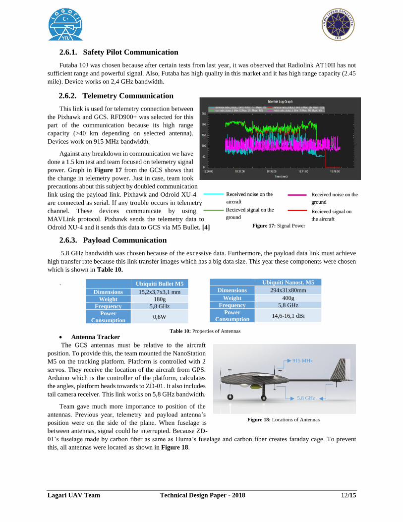
2.6.2. Telemetry Communication
This link is used for telemetry connection between
the Pixhawk and GCS. RFD900+ was selected for this
part of the communication because its high range
capacity (>40 km depending on selected antenna).
Devices work on 915 MHz bandwidth.
Against any breakdown in communication we have
done a 1.5 km test and team focused on telemetry signal
power. Graph in Figure 17 from the GCS shows that
the change in telemetry power. Just in case, team took
precautions about this subject by doubled communication
link using the payload link. Pixhawk and Odroid XU-4
are connected as serial. If any trouble occurs in telemetry
channel. These devices communicate by using
MAVLink protocol. Pixhawk sends the telemetry data to
Odroid XU-4 and it sends this data to GCS via M5 Bullet. [4]
2.6.3. Payload Communication
5.8 GHz bandwidth was chosen because of the excessive data. Furthermore, the payload data link must achieve
high transfer rate because this link transfer images which has a big data size. This year these components were chosen
which is shown in Table 10.
.
• Antenna Tracker
The GCS antennas must be relative to the aircraft
position. To provide this, the team mounted the NanoStation
M5 on the tracking platform. Platform is controlled with 2
servos. They receive the location of the aircraft from GPS.
Arduino which is the controller of the platform, calculates
the angles, platform heads towards to ZD-01. It also includes
tail camera receiver. This link works on 5,8 GHz bandwidth.
Team gave much more importance to position of the
antennas. Previous year, telemetry and payload antenna’s
position were on the side of the plane. When fuselage is
between antennas, signal could be interrupted. Because ZD-
01’s fuselage made by carbon fiber as same as Huma’s fuselage and carbon fiber creates faraday cage. To prevent
this, all antennas were located as shown in Figure 18.
Ubiquiti Nanost. M5
Dimensions 294x31x80mm
Weight 400g
Frequency 5,8 GHz
Power
Consumption 14,6-16,1 dBi
Ubiquiti Bullet M5
Dimensions 15,2x3,7x3,1 mm
Weight 180g
Frequency 5,8 GHz
Power
Consumption 0,6W
915 MHz
5.8 GHz
Figure 18: Locations of Antennas
Figure 17: Signal Power
Recieved signal on
the aircraft
Received noise on the
ground
Received noise on the
aircraft
Recieved signal on the
ground
Table 10: Properties of Antennas

Lagari UAV Team Technical Design Paper - 2018 13/15
2.7. Air Delivery
2.7.1. Design
Firstly, the requirements were listed for this task. The
system should be easily manufactured and detachable from the
fuselage. It was located near the CG in order to keep the aircraft
stable after the drop. To increase the accuracy of the airdrop
system, a rapid and high-quality algorithm was developed. ABS
(Acrylonitrile butadiene styrene) was used as a material for low
weight and durability of the water bottle shell.
The challenge that we had with the drop system was lack
of space in the fuselage. To overcome the challenge, the drop
system was designed in a simple and effective way. Also, it was
placed outside the fuselage. The system consists of two 3D
printed parts, servo, wire and fiberglass tube. It operates as shown in
the Figure 19.
2.7.2. Algorithm
The algorithm works as described; when the airdrop mission is started, the Mission Planner starts to calculate the
distance between the UAV and the airdrop position. This calculation is done with taking into consideration the UAV’s
speed, wind speed, altitude and the system delays. The separation is triggered by the servo mechanism when it reaches
the airdrop range. Range is calculated by the algorithm with help of these formulas:
𝐷 = 𝐶𝐷 ∗ 𝜑 ∗ 𝑉2 ∗ 𝐴 ∗ 1
2 𝑡 = √
2ℎ
(𝑔−𝑎𝑑𝑟𝑎𝑔) 𝑋 = 𝑉𝑈𝐴𝑉 ∗ 𝑡 − 𝑎𝑑𝑟𝑎𝑔 ∗
1
2∗ 𝑡2
2.8. Cyber Security
In our unmanned aerial vehicle, many security precautions and communication protocols are used in order to
provide security in communication system.
COMPONENT RISKS MITIGATION FALLBACK PLAN
Telemetry Jamming A second telemetry communication over
5.8 GHz is preferred.
Return to home plan of
Pixhawk starts. If no
connection in ten minutes,
fail-safe landing occurs.
Wi-Fi Link Spoofing WPA/WPA2 security and encryption None.
Wi-Fi Link Monitoring WPA/WPA2 security and encryption
If any monitoring is detected,
database locks itself and
secures the data.
RC Receiver Hacking
RC transmitter and receiver are paired
before competition, and FHSS prevents
others from hijacking the link without
knowing the initial seed.
Change the flight mode over
the Mission Planner and
continue the flight.
RC Receiver Jamming RC receiver is placed on the bottom of
the airplane to guarantee the connection.
Change the flight mode over
the Mission Planner and
continue the flight
GPS Jamming Two GPS modules are placed on different
places to make connection safe.
Airplane waits 3 mins. for
connection. After that failsafe
mode starts.
Figure 19: Air drop mechanism
Table 11: Mission Table
Lagari UAV Team Technical Design Paper - 2018 14/15
3. Safety, Risks & Mitigations
Several sub-teams from different disciplines work together during manufacturing and integration of UAV.
Throughout this process, there are many hazardous situations that may affect the health of team members and the
efficiency of manufacturing. These risks are considered in detail at the beginning of the process. Thus, manufacturing
has been tried to be completed successfully considering these risks. Lagari kept safety at the forefront, analyzed risks
and took precautions according to those risks.
3.1. Development Risks & Mitigations
There might be accidents and injuries during the manufacturing and testing of systems. To avoid such
situations, team leaders take necessary precautions to ensure the safety of all team members. A person named
Turquoise Man was chosen for the flight tests. This person inspects the team's safety factors in manufacturing and
testing and makes the necessary warnings. For instance, to remind you that in the engine test you have to stop 30cm
from the propeller.
On the other hand, some problems such as equipment breakdown, faulty manufacturing or even an injury of a
member may cause delays on the whole process. Thus, Lagari prepared a checklist which is applied before every-
flight to ensure operability of the whole system. After testing all subsystems one by one, all subsystems has been
integrated into the entire system. Some of important risks are shown in Table 12.
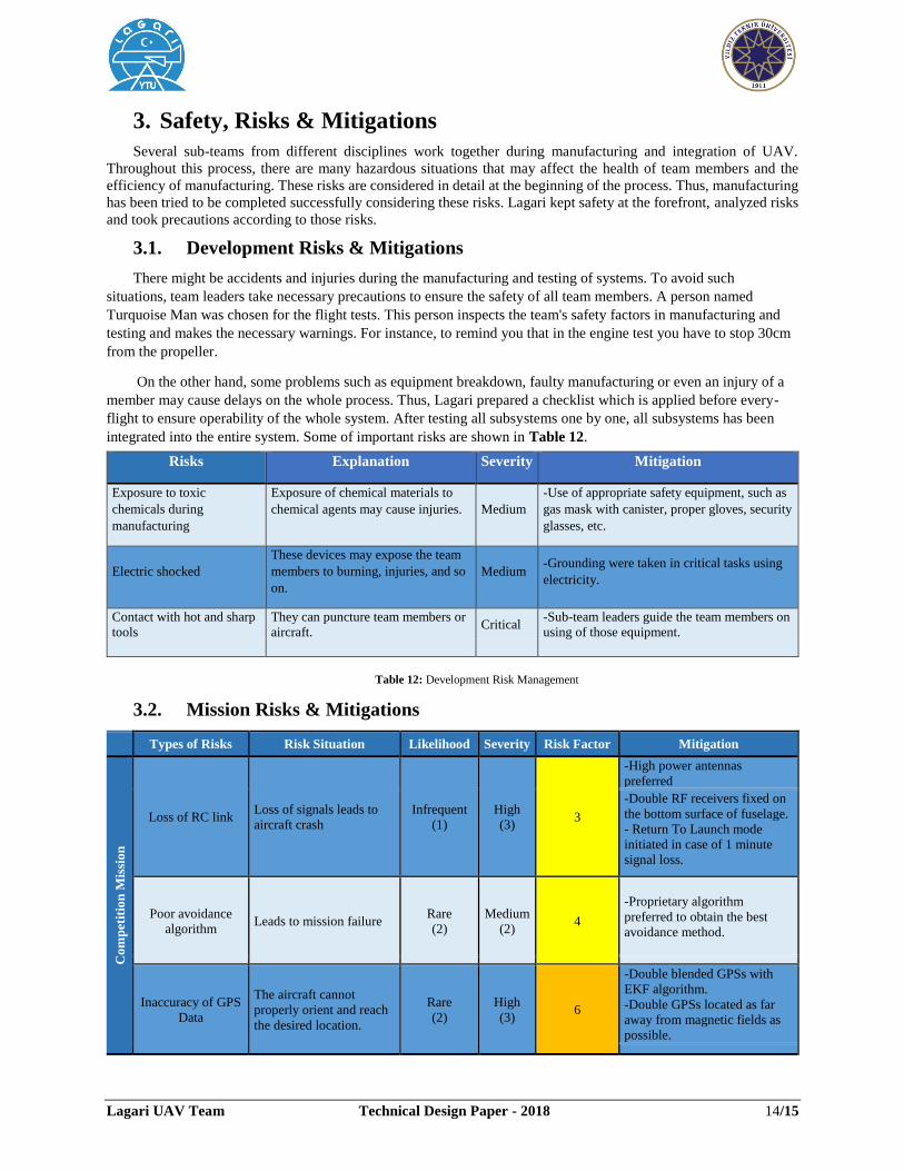
3.2. Mission Risks & Mitigations
Types of Risks Risk Situation Likelihood Severity Risk Factor Mitigation
Co
mp
etit
ion
Mis
sio
n
Loss of RC link Loss of signals leads to
aircraft crash
Infrequent
(1)
High
(3) 3
-High power antennas
preferred
-Double RF receivers fixed on
the bottom surface of fuselage.
- Return To Launch mode
initiated in case of 1 minute
signal loss.
Poor avoidance
algorithm Leads to mission failure
Rare
(2)
Medium
(2) 4
-Proprietary algorithm
preferred to obtain the best
avoidance method.
Inaccuracy of GPS
Data
The aircraft cannot
properly orient and reach
the desired location.
Rare
(2)
High
(3) 6
-Double blended GPSs with
EKF algorithm.
-Double GPSs located as far
away from magnetic fields as
possible.
Risks Explanation Severity Mitigation
Exposure to toxic
chemicals during
manufacturing
Exposure of chemical materials to
chemical agents may cause injuries. Medium
-Use of appropriate safety equipment, such as
gas mask with canister, proper gloves, security
glasses, etc.
Electric shocked
These devices may expose the team
members to burning, injuries, and so
on.
Medium -Grounding were taken in critical tasks using
electricity.
Contact with hot and sharp
tools
They can puncture team members or
aircraft. Critical
-Sub-team leaders guide the team members on
using of those equipment.
Table 12: Development Risk Management

Lagari UAV Team Technical Design Paper - 2018 15/15
Au
ton
om
ou
s F
lig
ht
Loss of power to
Pixhawk
Complete loss of control
of aircraft leading to
crash.
Infrequent
(1)
High
(3) 3
-Triple redundant power to
autopilot by power module,
BEC to servo and USB from
Payload Box
Failure of avionic
components
It leads failure of flight or
even any crash.
Frequent
(3)
High
(3) 9
-Two avionic boxes named
payload box and control box
were designed to reduce any
failure.
Failure of
Autonomous
Control Algorithm
Insufficient autonomous
flight
Infrequent
(1)
High
(3) 3
-Backup autonomous flight
mode embedded into Pixhawk
as a fail-safe mode.
Tes
tin
g
Cable connectivity
error
A cable fault that occur
during flight may cause
the aircraft to crash.
Frequent
(3)
High
(3)
9
-Connector and cable
assemblies fitted in the
fuselage.
-Sockets used at the ends of the
cable.
Damage to Li-Po
Batteries
It may cause fire in the
UAV.
Frequent
(3)
High
(3) 9
- Covered Li-Po Batteries with
a hard plastic material to make
them rigid.
- Insulated cells with a
nonflammable rubber.
Vortex wind druing
landing
It can cause damage on
landing gear or fuselage
Infrequent
(1)
High
(3) 3
-Using strengthened and spare
landing gear and fuselage.
4. Conclusion
This paper summarizes a work done by students from the Mechatronic Engineering Department of the Yildiz
Technical University in preparation for the AUVSI SUAS 2018. Throughout the year, the Lagari designed, developed
and tested the ZD-01 system with an improved software for payload control and an enhanced hardware for flight
control. Advanced algorithms were written to accomplish competition tasks. Numerous ground and flight tests were
conducted to confirm the UAS capabilities and assured its excellence in the SUAS competition.
5. References
[1] Daniel P. Raymer, “Aircraft Design: A Conceptual Approach. 5th ed.” Amer Inst of Aeronautics, 2012.
[2] Park, Sanghyuk, John Deyst, and Jonathan How. "A new nonlinear guidance logic for trajectory
tracking." AIAA guidance, navigation, and control conference and exhibit. 2004.
[3] Sarunic, Peter W. Development of GPS Receiver Kalman Filter Algorithms for Stationary, Low-Dynamics, and
High-Dynamics Applications. Defence Science and Technology Group Edinburgh, South Australia Australia, 2016.
[4] Behrouz A. Forouzan, “Data Communication and Networking 5th ed.”, New York: McGraw-Hill. 2012
Table 13: Risk Management
Likelihood factors are rated as Frequent, Rare and Infrequent. Severity is rated as High, Medium and Low respectively
numbering as 3, 2, 1. Following calculation is manipulated (Risk factor = Likelihood x Impact). If risk factor is less than 3, it is
acceptable for risk management. Otherwise it is unacceptable and a specific mitigation is needed