laboratory centrifuge 2-6e operating manual - labmakelaar · centrifuge is to be familiar with the...
TRANSCRIPT

Laboratory Centrifuge 2-6E
Operating Manual
From Serial No 124764
Please retain for later use!

Dear Customer, Congratulations on your purchase of a SIGMA laboratory centrifuge. You have selected a device that combines many advantages. The SIGMA 2-6E is a small, microprocessor-controlled centrifuge. The electronic operation control enables a trouble-free use of the centrifuge. With its quiet 3-phase maintenance-free drive, operation without any carbon dust pollution is guaranteed. Your device is equipped with user-friendly options that make the operation and standard settings easier for you. Built-in error-detecting functions keep the user from entering erroneous values and they also check the entire operation. All of the settings are executed via the control panel with a coated surface that protects the device against moisture and dust. In addition, the interior of the centrifuge is also rather easy to clean. We offer you a device that combines functional variety along with practical applications. Our centrifuges are carefully manufactured according to the highest quality standards, in which we are certain that your demands will always be met. We wish you much success in the use of the centrifuge. SIGMA Laborzentrifugen GmbH An der Unteren Söse 50 Postfach 17 13 D-37520 Osterode D-37507 Osterode Phone: +49 (0) 5522/5007-0 – Fax: ++49 (0) 5522/5007-12 Internet : www.sigma-zentrifugen.deE-mail : [email protected] Service Phone: +49 (0) 5522/5007-8425 Fax: +49 (0) 5522/5007-9425 © 2008 by SIGMA Laborzentrifugen GmbH Modifications reserved.
Operating Manual SIGMA 2-6E page 3 of 71 Version 04/2008

Konformitätserklärung (2006/42/EG; 2006/95/EG; 2004/108/EG)
Declaration of Conformity (2006/42/EG; 2006/95/EG; 2004/108/EG)
Déclaration de conformité (2006/42/EG; 2006/95/EG; 2004/108/EG)
Die nachfolgend bezeichnete Maschine wurde in Übereinstimmung mit den Richtlinien 2006/42/EG; 2006/95/EG und 2004/108/EG hergestellt und geprüft. The following machine is manufactured and tested in compliance with directives 2006/42/EG; 2006/95/EG und 2004/108/EG. La machine désignée ci-dessous est produit et examiné conforme aux directives 2006/42/EG; 2006/95/EG und 2004/108/EG Bezeichnung der Maschine: Laborzentrifuge Machine: Laboratory Centrifuge Désignation de la machine: Centrifugeuse de laboratoire Maschinentyp : 2 – 6 E Type: Type de la machine: Bestell Nr. : 10208, 10209 Part No.: Réf. usine: Normen: EN 61010-2-020:2007 Standards: EN 61000-3-2:2006; EN 61000-3-3:1995, A2:2005 Normes : EN 61326-1:2006 Sigma Laborzentrifugen An der Unteren Söse 50 D-37520 Osterode
28.03.2008 Geschäftsführer Managing Director Directeur Gérant ........................................................................ Fabr. Nr. Serial No. Numéro de série
2-6E 20080328.DOC
Bedienungsanleitung SIGMA 2-6E Seite 5 von 71 Stand 04/2008

Table of Contents
1 General Information 11 1.1 Importance of the Operating Manual 11 1.2 Intended Use 11 1.3 Technical Data 13
1.3.1 Ambient Temperature 13 1.4 Scope of Supply 15 1.5 Standards and Regulations 15
2 Safety Instructions and Hazard Warnings 16 2.1 Symbols used in the Safety Instructions 16 2.2 Symbols used in the Operating Manual 17 2.3 Informal Notes on Safety 17 2.4 Safety Instructions for Centrifugation 18
2.4.1 Special Instructions 18 2.4.2 Resistance of Plastics 19
2.5 Prohibited Centrifuging Operations and Hazard Warnings 19 2.5.1 Special Hazards 20
2.6 Checks by the Operator 21 2.7 Instructions for Emergency Situations 21 2.8 Remaining Hazards 21
3 Transport and Storage 22 3.1 Dimensions and Weight 22 3.2 Notes on Transport 22 3.3 Notes on Storage 22
4 Set-up and Connection 23 4.1 Unpacking the Centrifuge 23
4.1.1 Transport Safety Device 23 4.2 Installation 24
4.2.1 Installation Site 24 4.2.2 Connection 24 4.2.3 Fuses/Emergency Circuit Breaker on Site 24
Bedienungsanleitung SIGMA 2-6E Seite 7 von 71 Stand 04/2008
5 Using the Centrifuge 255.1 Description 25
5.1.1 Operating Elements 25 5.1.1.1 Operating Panel 26 5.1.1.2 Name Plate 26
5.1.2 Construction and Constructive Safety Measures 27 5.1.3 Drive 27 5.1.4 Operation and Display 27 5.1.5 Electronic System 27 5.1.6 Safety Devices 28
5.1.6.1 Lid Lock and Lid Closing Device 28 5.1.6.2 Standstill Monitoring 28 5.1.6.3 System Check 28 5.1.6.4 Ground Wire Check 28
5.2 Initial Start-Up 29 5.2.1 Switching the Centrifuge ON 29 5.2.2 Opening and Closing the Lid 29 5.2.3 Installation of Rotors 30 5.2.4 Installation of Accessories 31
5.2.4.1 Carrier Systems 31 5.2.4.2 Tubes 32
5.2.5 Service Life of Rotors and Accessories 32 5.2.6 Starting the Centrifuge 33 5.2.7 Interrupting a Centrifugation Run 33
5.2.7.1 Interrupting a Deceleration Process 33 5.2.7.2 Softstart and Softstop Function 33
5.3 Display/Program Options 34 5.3.1 Time 34
5.3.1.1 Changing the Time Increments 35 5.3.1.2 Short Run 35 5.3.1.3 Continuous Run 35
5.3.2 Speed 36 5.3.2.1 Changing the Speed Increments 36
5.3.3 Relative Centrifugal Force (RCF) 37 5.3.4 Rotor 37
Bedienungsanleitung SIGMA 2-6E Seite 8 von 71 Stand 04/2008
5.3.5 Program 38 5.3.5.1 Saving the Current Settings 38 5.3.5.2 Calling Up Stored Programs 38
5.3.6 Lockdown 39 5.3.6.1 Permanent Lockdown 39
5.3.7 Activating/Deactivating the Automatic Lid Opening Function 40 5.3.8 Activating/Deactivating the Sound Signal 40
6 Malfunctions and Error Correction 41 6.1 Error Mode 41 6.2 Error Correction 41
6.2.1 No Indication on the Display 41 6.2.2 Centrifuge cannot be started 41 6.2.3 Centrifuge decelerates during Operation 41 6.2.4 Lid cannot be opened 42 6.2.5 Emergency Lid Release 42 6.2.6 Error Codes 43 6.2.7 Service Contact 43
7 Care and Maintenance 44 7.1 Cleaning and Care 44
7.1.1 Centrifuge 44 7.1.2 Accessories 45
7.1.2.1 Plastic Accessories 45 7.1.2.2 Aluminum Accessories 45
7.1.3 Rotor, Buckets, and Multiple Carriers 46 7.1.4 Load-bearing bolts 46 7.1.5 Glass Breakage 47
7.2 Sterilization and Disinfection of the Rotor Chamber and Accessories 47 7.2.1 Autoclaving 48
8 Disposal 49 8.1 Disposal of the Centrifuge 49 8.2 Disposal of the Packaging 49
9 Warranty and Liability 49
10 Suitable Accessories 50 10.1 Graphical Representation of the Rotors 56
Bedienungsanleitung SIGMA 2-6E Seite 9 von 71 Stand 04/2008
11 Appendix 57 11.1 Formulae – Mathematical Relations 57
11.1.1 Relative Centrifugal Force (RCF) 57 11.1.2 Density 57 11.1.3 Speed-Gravitational-Field-Diagram 57
11.2 Declaration of Decontamination/Return Declaration 59 11.3 Resistance Data 65
12 Index 69
Bedienungsanleitung SIGMA 2-6E Seite 10 von 71 Stand 04/2008
1 General Information
1.1 Importance of the Operating Manual
• A fundamental requirement for the safe and trouble-free operation of the centrifuge is to be familiar with the fundamental safety instructions and all possible hazards.
• The operating manual includes important information concerning the safe
operation of the centrifuge.
• This operating manual and in particular the notes on safety and hazards must be observed by all persons operating the centrifuge.
• In addition, the local rules and regulations for the prevention of accidents
must be complied with. 1.2 Intended Use
Centrifuges are power-driven machines that separate liquids from solid matter, liquid mixtures, or solid mixtures by centrifugal force (see BGR 500, chapter 2.11, part 3). They are solely intended for this purpose. Any other use beyond this area of application is regarded as improper use. SIGMA Laborzentrifugen GmbH cannot be held liable for any damage resulting from such improper use. The intended use also includes • observation of all the notes and instructions included in the operating manual
and
• compliance with the care, cleaning, and maintenance instructions.
Operating Manual SIGMA 2-6E page 11 of 71 Version 04/2008

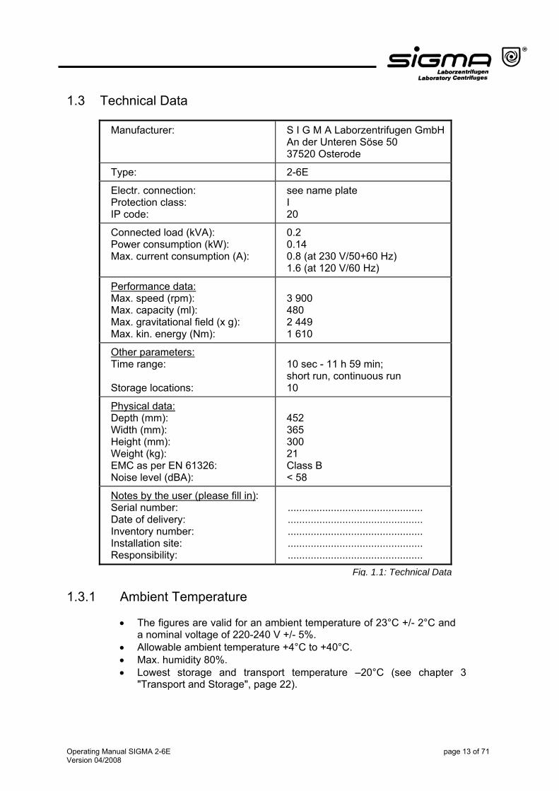
1.3 Technical Data
Manufacturer: S I G M A Laborzentrifugen GmbH An der Unteren Söse 50 37520 Osterode
Type: 2-6E
Electr. connection: Protection class: IP code:
see name plate I 20
Connected load (kVA): Power consumption (kW): Max. current consumption (A):
0.2 0.14 0.8 (at 230 V/50+60 Hz) 1.6 (at 120 V/60 Hz)
Performance data: Max. speed (rpm): Max. capacity (ml): Max. gravitational field (x g): Max. kin. energy (Nm):
3 900 480 2 449 1 610
Other parameters: Time range: Storage locations:
10 sec - 11 h 59 min; short run, continuous run 10
Physical data: Depth (mm): Width (mm): Height (mm): Weight (kg): EMC as per EN 61326: Noise level (dBA):
452 365 300 21 Class B < 58
Notes by the user (please fill in): Serial number: Date of delivery: Inventory number: Installation site: Responsibility:
............................................... ............................................... ............................................... ............................................... ...............................................
Fig. 1.1: Technical Data
1.3.1 Ambient Temperature
• The figures are valid for an ambient temperature of 23°C +/- 2°C and a nominal voltage of 220-240 V +/- 5%.
• Allowable ambient temperature +4°C to +40°C. • Max. humidity 80%. • Lowest storage and transport temperature –20°C (see chapter 3
"Transport and Storage", page 22).
Operating Manual SIGMA 2-6E page 13 of 71 Version 04/2008

1.4 Scope of Supply The centrifuge comprises: • Connecting cable Part no. 269 010 • Rotor wrench Part no. 930 050 • 20 ml slushing oil Part no. 70 104 • 1 tube of grease for load-bearing bolts Part no. 70 284 • Spare fuses Part no. 70149 for 230 V Part no. 70102 for 120 V Documentation: Operating manual incl. • EU Declaration of Conformity (page 5) • Equipment Decontamination Certificate (page 63) Accessories according to your order, our order confirmation, and our delivery note.
1.5 Standards and Regulations Please refer to the enclosed EU Declaration of Conformity (page 5).
Operating Manual SIGMA 2-6E page 15 of 71 Version 04/2008
2 Safety Instructions and Hazard Warnings
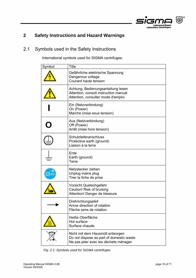
2.1 Symbols used in the Safety Instructions International symbols used for SIGMA centrifuges: Symbol Title
Gefährliche elektrische Spannung Dangerous voltage Courant haute tension
Achtung, Bedienungsanleitung lesen Attention, consult instruction manual Attention, consulter mode d'emploi
Ein (Netzverbindung) On (Power) Marche (mise sous tension)
Aus (Netzverbindung) Off (Power) Arrêt (mise hors tension)
Schutzleiteranschluss Protective earth (ground) Liaison à la terre
Erde Earth (ground) Terre
Netzstecker ziehen Unplug mains plug Tirer la fiche de prise
Vorsicht Quetschgefahr Caution! Risk of bruising Attention! Danger de blessure
Drehrichtungspfeil Arrow direction of rotation Flèche sens de rotation
Heiße Oberfläche Hot surface Surface chaude
Nicht mit dem Hausmüll entsorgen Do not dispose as part of domestic waste Ne pas jeter avec les déchets ménager
O
I
Fig. 2.1: Symbols used for SIGMA centrifuges
Operating Manual SIGMA 2-6E page 16 of 71 Version 04/2008
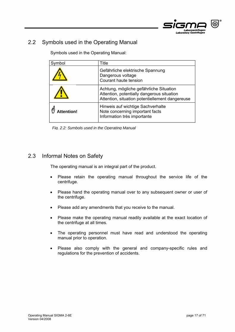
2.2 Symbols used in the Operating Manual Symbols used in the Operating Manual: Symbol Title Gefährliche elektrische Spannung
Dangerous voltage Courant haute tension
Achtung, mögliche gefährliche Situation Attention, potentially dangerous situation Attention, situation potentiellement dangereuse
Attention!
Hinweis auf wichtige Sachverhalte Note concerning important facts Information très importante
Fig. 2.2: Symbols used in the Operating Manual 2.3 Informal Notes on Safety
The operating manual is an integral part of the product. • Please retain the operating manual throughout the service life of the
centrifuge.
• Please hand the operating manual over to any subsequent owner or user of the centrifuge.
• Please add any amendments that you receive to the manual.
• Please make the operating manual readily available at the exact location of
the centrifuge at all times.
• The operating personnel must have read and understood the operating manual prior to operation.
• Please also comply with the general and company-specific rules and
regulations for the prevention of accidents.
Operating Manual SIGMA 2-6E page 17 of 71 Version 04/2008
2.4 Safety Instructions for Centrifugation
• Ensure that the centrifuge was set up properly (see section 4.2 “Installation”, page 24).
• Check the centrifuge, rotor, and accessories for external signs of damage
prior to start-up.
• Do not use the centrifuge with rotors and accessories that have not been approved by the manufacturer. In case of doubt contact our service team (See 6.2.7 "Service Contact", page 43).
• Ensure that the rotor is correctly fitted (see 5.2.3 "Installation of Rotors“, page
30).
• The load of the rotor as defined by the manufacturer and the maximum speed must not be exceeded (see the engraving on the rotor or bucket).
• The rotor must be loaded symmetrically at equal weights. • Please observe the instructions on the Installation of accessories (see 5.2.4,
page 31).
2.4.1 Special Instructions
• If liquids with a density > 1.2 g/cm3 are used, reduce the speed (see 11.1.2 "Density", page 57).
• Protective clothing is not required for the operation of the centrifuge.
The materials to be centrifuged may, however, require special safety measures (e.g. centrifugation of infectious, toxic, radioactive, or pathogenic substances).
• Spin infectious material in sealed rotors and buckets only.
• Avoid the corrosion of the centrifuge and its accessories by careful
maintenance (see chapter 7 "Care and Maintenance", page 44 ff).
• When not using the centrifuge, open the lid so that all liquids can evaporate.
• Stop the centrifuge immediately in the event of a malfunction. Eliminate the problem (see 6.2, page 41) or inform the SIGMA Laborzentrifugen GmbH service team (see 6.2.7 "Service Contact", page 43).
Operating Manual SIGMA 2-6E page 18 of 71 Version 04/2008
2.4.2 Resistance of Plastics Chemical influences have a strong effect on the polymeric chains of plastics, and therefore, on their physical properties. Plastic parts can be damaged if solvents, acids, or alkaline solutions are used. • Please refer to the resistance table (see 1.1, page 65)!
2.5 Prohibited Centrifuging Operations and Hazard Warnings Under the rules stipulated by the German trade association BGR 500, chapter 2.11, part 3, the operator is obliged to: • take measures in order to prevent all danger to life or health during work. • ensure that centrifuges are operated properly and entirely as intended (see
chapter 1.2 "Intended Use", page 11 of this Instruction Manual). • take measures for the safe opening of centrifuges. Please comply with the following hazard warnings. In the case of non-compliance with the instructions, the manufacturer cannot be held liable or subject to any warranty claims.
• Only persons who have read and understood the operating manual in whole are authorized to operate the centrifuge (see 2.3 "Informal Notes on Safety", page 17).
• Keep informed about local fire prevention regulations and measures to
contain harmful emissions (depending on the substances to be centrifuged). • Do not use the centrifuge if it was installed incorrectly.
• Do not use the centrifuge without panels.
• Do not hit or move the centrifuge during its operation.
• Do not lean against or rest on the centrifuge during its operation. • Maintain a safety distance of at least 30 cm around the centrifuge. • Do not store any dangerous goods in the centrifuge area. • Only use the centrifuge with rotors and accessories that have been approved
by the manufacturer. We explicitly warn against the use of equipment of poor quality. Breaking glass or bursting vessels can cause dangerous imbalances at high speeds.
• Do not spin any substances that could damage the material of the rotors and
buckets of the centrifuge in any way. Highly corrosive substances, for
Operating Manual SIGMA 2-6E page 19 of 71 Version 04/2008
example, damage the material and affect the mechanical strength of the rotors and buckets.
• Infectious, toxic, pathogenic, and radioactive substances must be centrifuged
in certified rotors and vessels. Take suitable precautions for your own safety if there is a risk of toxic, radioactive, or pathogenic contamination.
• Please comply with the special precautions for taking care of the
centrifuges and accessories. These are measures for maintaining operational safety! (see chapter 7 "Care and Maintenance", page 44)
Attention! • Ensure that all repairs are performed only by authorized and specialized
personnel (see 6.2.7 "Service Contact", page 43).
2.5.1 Special Hazards • Do not open the lid when the rotor is in motion!
• Do not reach into the rotor chamber when the rotor is in motion!
• Do not use the centrifuge if the rotor is overloaded. (see 2.4 " Safety Instructions for Centrifugation", page 18).
• Do not use the centrifuge if the rotors and inserts show signs of corrosion or
other defects. • Do not use the centrifuge if the rotor is loaded asymmetrically.
• Do not use the centrifuge with tubes that are excessively long. • Do not use the centrifuge within hazardous locations.
• Do not spin explosive or inflammable substances. • Materials that chemically react with each other with a high level of energy are
prohibited.
Operating Manual SIGMA 2-6E page 20 of 71 Version 04/2008
2.6 Checks by the Operator Check all of the safety-relevant parts of the centrifuge at least once per month for any visible signs of damage (e.g. cracks, corrosion). This applies particularly to the following:
• Concentricity of the motor shaft:
− Visual inspection: Slowly rotate the rotor by hand without the rotor tie-down screw. If the motor shaft does not turn around on a perpendicular axis, the motor and motor shaft must be replaced.
− Refit the rotor correctly after visual inspection (see 5.2.3 "Installation of Rotors", page 30).
− Auditory inspection: Check the unit for atypical running noises. • Fastening of the trunnion pins in the rotor • Screw connections
• Rotors and accessories. (see 5.2.5 "Service Life of Rotors an Accessories",
page 32).
2.7 Instructions for Emergency Situations
• If an emergency arises, actuate the emergency switch at the exit or in the
room next door (see 4.2.3 "Fuses/Emergency Circuit Breaker on Site", page 24).
Fire-fighting measures or measures for the containment of harmful emissions depend on the local conditions and on the substances processed in the centrifuge. Please be informed about the rules and regulations that are applicable on-site.
2.8 Remaining Hazards
The centrifuge was built state-of-the-art and according to the accepted safety rules. Danger to life and limb of the user or of third parties, or impairments of the unit or other material assets cannot be completely excluded when the centrifuge is used. • Use the centrifuge only for the purpose that it was originally intended for (see
1.2, page 11). • Use the centrifuge only if it is in a perfect running state.
• Immediately eliminate any problems that can affect safety.
Operating Manual SIGMA 2-6E page 21 of 71 Version 04/2008
3 Transport and Storage
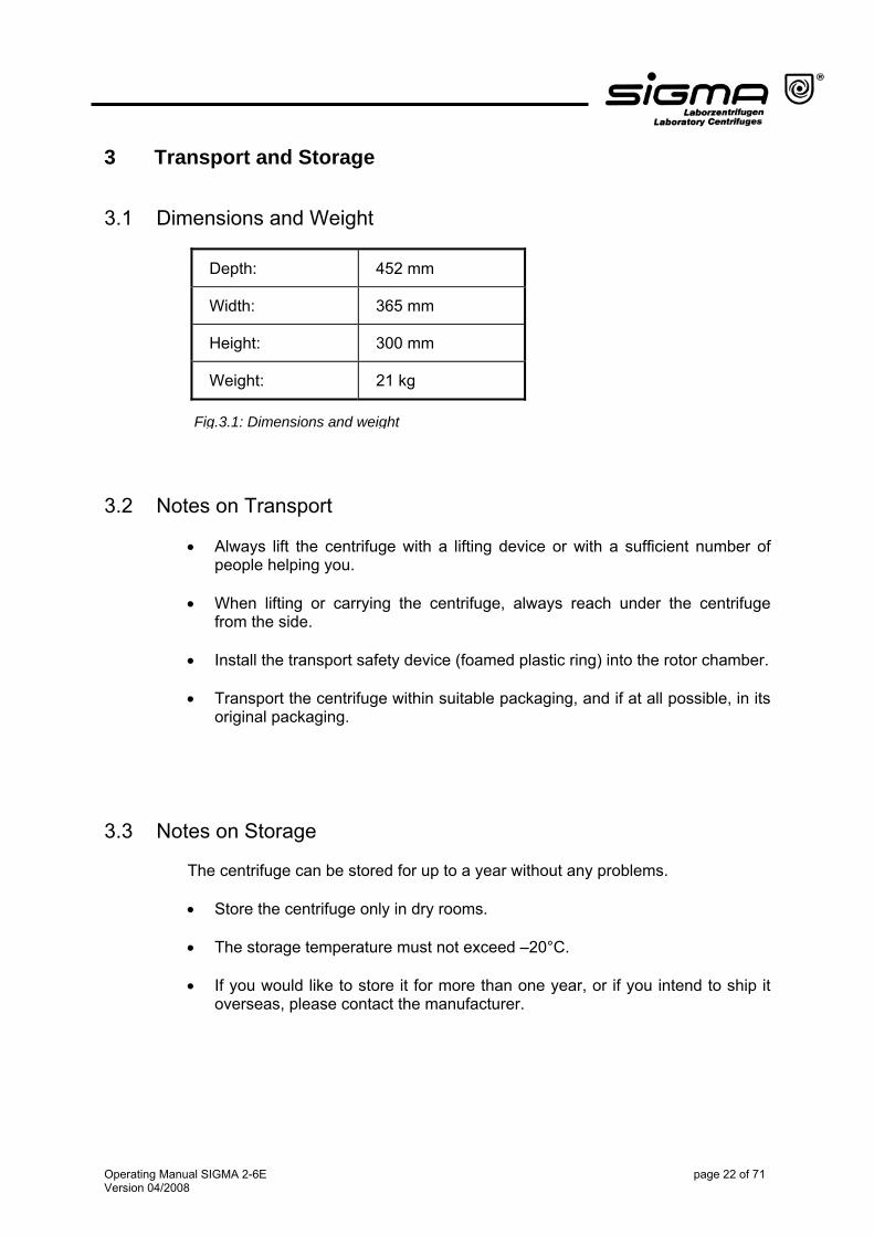
3.1 Dimensions and Weight
Depth: 452 mm
Width: 365 mm
Height: 300 mm
Weight: 21 kg
Fig.3.1: Dimensions and weight
3.2 Notes on Transport
• Always lift the centrifuge with a lifting device or with a sufficient number of
people helping you.
• When lifting or carrying the centrifuge, always reach under the centrifuge from the side.
• Install the transport safety device (foamed plastic ring) into the rotor chamber.
• Transport the centrifuge within suitable packaging, and if at all possible, in its
original packaging.
3.3 Notes on Storage The centrifuge can be stored for up to a year without any problems. • Store the centrifuge only in dry rooms. • The storage temperature must not exceed –20°C.
• If you would like to store it for more than one year, or if you intend to ship it
overseas, please contact the manufacturer.
Operating Manual SIGMA 2-6E page 22 of 71 Version 04/2008
4 Set-up and Connection 4.1 Unpacking the Centrifuge
• Open the cardboard box. • Take out the box containing the accessories.
• Remove the upper foam cushion.
• Lift the centrifuge upwards with a lifting device or with a sufficient number of
people to lift it safely. When lifting or carrying the centrifuge, always reach under the centrifuge from the side.
Attention! The centrifuge weighs approx. 21 kg! Please retain the packaging for any possible future transport of the centrifuge.
4.1.1 Transport Safety Device The transport safety device of the SIGMA 2-6E centrifuge consists of a foamed plastic ring in the centrifuge chamber. It must be removed prior to start-up. Procedure: • Open the lid. To do so,
− use the emergency release of the lid (see 6.2.5, page 42) if the centrifuge is not connected to the power supply
or − connect the centrifuge to the power supply and press the lid key.
• Remove the foamed plastic ring from the rotor chamber, by lifting it carefully on one side.
• Please retain the transport safety device for the possibility of the return of the
centrifuge.
Operating Manual SIGMA 2-6E page 23 of 71 Version 04/2008
4.2 Installation
4.2.1 Installation Site All the energy supplied to the centrifuge is converted into heat and emitted to ambient air. • Ensure sufficient ventilation. • Keep a safety distance of at least 30 cm from the wall so that the vents in the
centrifuge remain fully effective. • Do not position the centrifuge near heat generators. • Avoid direct sunlight (UV radiation). • The table must be stable and have a solid, even surface.
Attention! During transport from cold to warmer places, condensation will collect inside the centrifuge. It is important to allow sufficient time for drying before the centrifuge can be used again.
4.2.2 Connection The operating voltage on the name plate must correspond to the local supply voltage!
SIGMA laboratory centrifuges are units of safety class I in accordance with DIN VDE 0700 and have a three-wire power cord (2.5 m) and a shockproof right-angle plug. On the back, next to the mains power input, there is an additional ground wire connector (see Fig. 5.2, page 25) where a separate ground wire can be connected. This ensures that the admissible leakage current cannot shock anyone if a problem with the protective ground wire system were to occur. Only authorized and specialized personnel are permitted to connect the unit. Please contact the head of our service team (see 6.2.7 "Service Contact", page 43).
4.2.3 Fuses/Emergency Circuit Breaker on Site
Typically, the centrifuges must be protected with 16 A fuses of class "B" or "L". An on-site emergency circuit breaker to disconnect the centrifuge from the power supply in the event of a malfunction is required (according to IEC 61010-2-20). This switch should be located away from the centrifuge, preferably outside the room where the centrifuge is located or at the exit of this room.
Operating Manual SIGMA 2-6E page 24 of 71 Version 04/2008
5 Using the Centrifuge
5.1 Description 5.1.1 Operating Elements
4
1
3 2
78
5
6
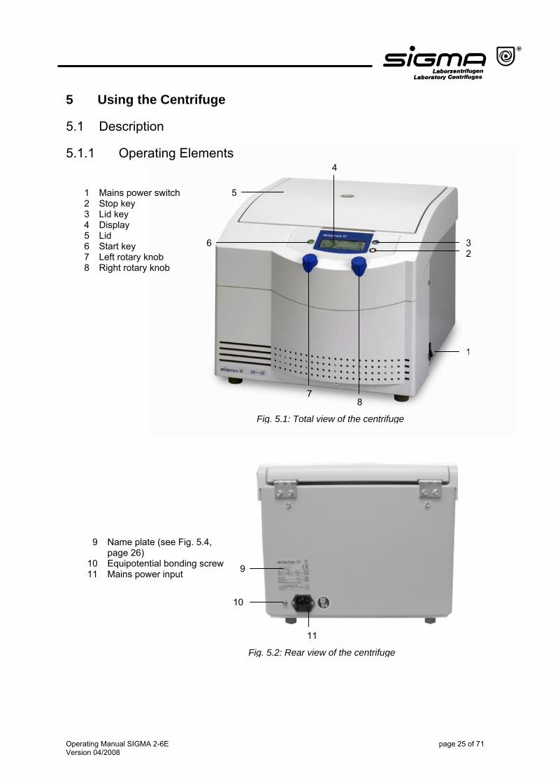
1 Mains power switch 2 Stop key 3 Lid key 4 Display 5 Lid 6 Start key 7 Left rotary knob 8 Right rotary knob
Fig. 5.1: Total view of the centrifuge
9 Name plate (see Fig. 5.4, page 26)
10 Equipotential bonding screw 11 Mains power input 9
10
11
Fig. 5.2: Rear view of the centrifuge
Operating Manual SIGMA 2-6E page 25 of 71 Version 04/2008
5.1.1.1 Operating Panel
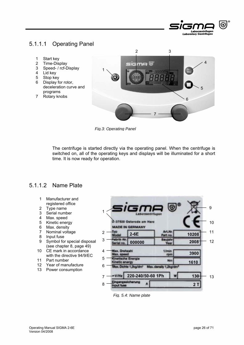
1 Start key 2 Time-Display 3 Speed- / rcf-Display 4 Lid key 5 Stop key 6 Display for rotor,
deceleration curve and programs
7 Rotary knobs
1
2 3
4
5
6
7
Fig.3: Operating Panel
The centrifuge is started directly via the operating panel. When the centrifuge is switched on, all of the operating keys and displays will be illuminated for a short time. It is now ready for operation.
5.1.1.2 Name Plate
1 Manufacturer and registered office
2 Type name 3 Serial number 4 Max. speed 5 Kinetic energy 6 Max. density 7 Nominal voltage 8 Input fuse 9 Symbol for special disposal
(see chapter 8, page 49) 10 CE mark in accordance
with the directive 94/9/EC 11 Part number 12 Year of manufacture 13 Power consumption
91
2
10 11 123
4
5
6
7 13
8
Fig. 5.4: Name plate
Operating Manual SIGMA 2-6E page 26 of 71 Version 04/2008

5.1.2 Construction and Constructive Safety Measures The centrifuge is installed within a solid construction. On the back, the lid is secured by solid hinges and on the front by two separate lid locks.
5.1.3 Drive The drive motor is a well-dimensioned, collector-less asynchronous motor.
5.1.4 Operation and Display The display is a hermetically sealed LCD display. It is operated by way of two rotary knobs and indicates the operating statuses.
5.1.5 Electronic System The microprocessor-controlled electronic system ensures a wide range of adaptations of the centrifuge for various tasks. The following parameters can be set: • Speed in steps of 100 or 10 rpm • Relative centrifugal force RCF in steps of 10 x g • Time between 10 sec and 11h 59min max. • Continuous run • Short run • Acceleration and deceleration curves • Storage and call-up of programs
Operating Manual SIGMA 2-6E page 27 of 71 Version 04/2008
5.1.6 Safety Devices Apart from the mentioned passive safety devices due to the solid design, the following active precautions are in place for your safety:
5.1.6.1 Lid Lock and Lid Closing Device The centrifuge can only be started when the lid is properly closed. The electrical locks must be locked. The lid can only be opened when the rotor has stopped. If the lid is opened by way of the emergency release system during operation, the centrifuge will immediately switch off and decelerate brakeless. If the lid is open, the drive is completely separated from the mains power supply, i.e. the centrifuge cannot be started (see 6.2.5 "Emergency Lid Release", page 42).
5.1.6.2 Standstill Monitoring
Opening of the centrifuge lid is only possible if the rotor is at a standstill. This standstill is checked by the microprocessor.
5.1.6.3 System Check
An internal system check monitors the data transfer and sensor signals with regard to plausibility. Errors are detected with extreme sensitivity and displayed as error messages with a number on the speed display (see 6.2.6 "Error Codes", page 43).
5.1.6.4 Ground Wire Check
For the ground wire check, there is an equipotential bonding screw on the rear panel of the centrifuge. A ground wire check can be carried out by authorized and specialized personnel using a suitable measuring instrument (see 4.2.2 "Connection“, page 24). Please contact the head of our service team (see 6.2.7 "Service Contact", page 43).
Operating Manual SIGMA 2-6E page 28 of 71 Version 04/2008

5.2 Initial Start-Up Before the initial start-up, please ensure that your centrifuge is properly set up and installed (see 4.2 "Installation", page 24).
5.2.1 Switching the Centrifuge ON • Press the mains power switch on the right side of the front (see Fig. 5.1, page
25). The centrifuge display then illuminates.
5.2.2 Opening and Closing the Lid
The lid can be opened if the centrifuge is at a standstill and if the lid key is illuminated. • Press the lid key in order to open the lid (see 5.3.7 "Activating/Deactivating
the Automatic Lid Opening Function", page 40). The centrifuge cannot be started if the lid is opened. • To close the lid, press on the left and right side of the lid to ensure that both
of the lid locks lock into place.
Attention! A flashing lid key indicates that only one lid lock has locked.
Operating Manual SIGMA 2-6E page 29 of 71 Version 04/2008
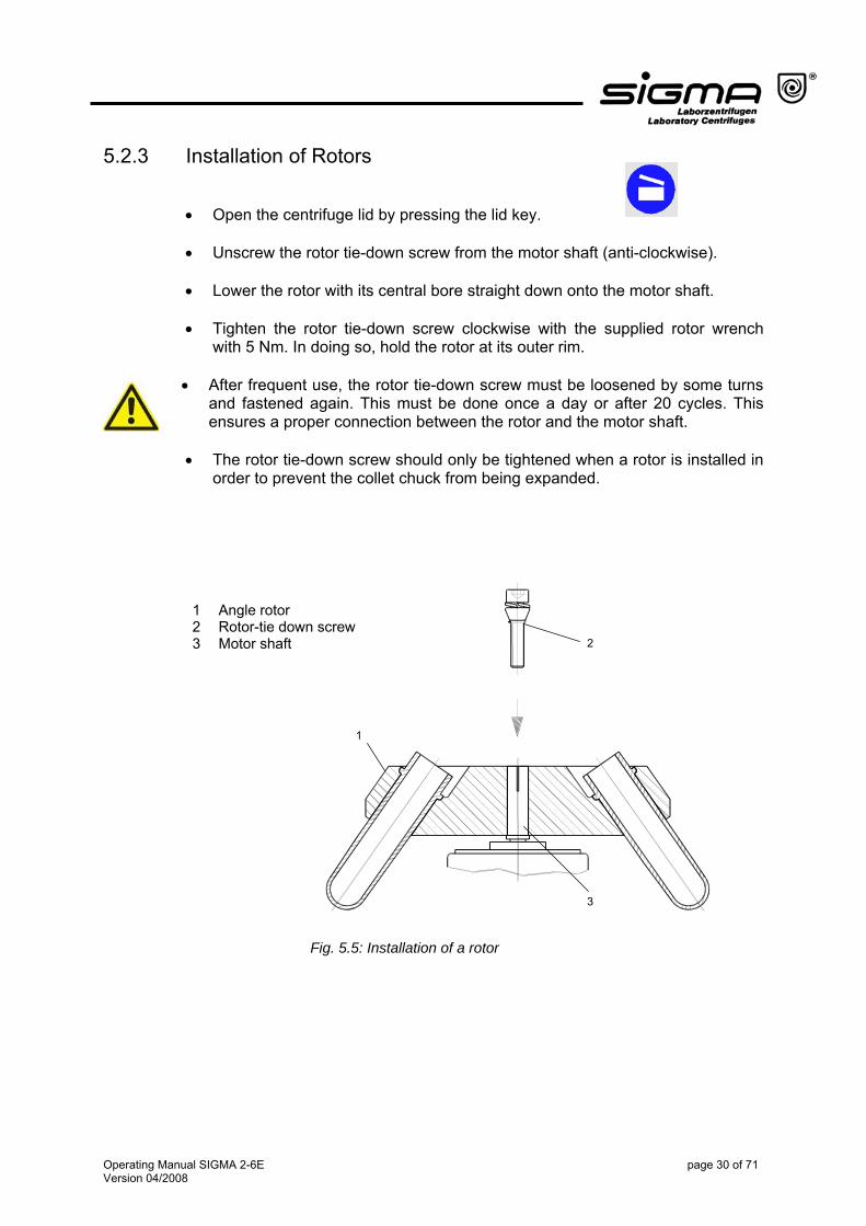
5.2.3 Installation of Rotors
• Open the centrifuge lid by pressing the lid key.
• Unscrew the rotor tie-down screw from the motor shaft (anti-clockwise).
• Lower the rotor with its central bore straight down onto the motor shaft.
• Tighten the rotor tie-down screw clockwise with the supplied rotor wrench with 5 Nm. In doing so, hold the rotor at its outer rim.
• After frequent use, the rotor tie-down screw must be loosened by some turns
and fastened again. This must be done once a day or after 20 cycles. This ensures a proper connection between the rotor and the motor shaft.
• The rotor tie-down screw should only be tightened when a rotor is installed in
order to prevent the collet chuck from being expanded.
3
1
2
1 Angle rotor 2 Rotor-tie down screw 3 Motor shaft
Fig. 5.5: Installation of a rotor
Operating Manual SIGMA 2-6E page 30 of 71 Version 04/2008
5.2.4 Installation of Accessories
• Only use vessels that are suitable for the rotor (see chapter 10 "Suitable Accessories", page 50 ff).
• Load all of the compartments of the swing-out rotors.
• Always load the opposite compartments of the rotors with the same
accessories and filling to avoid imbalance.
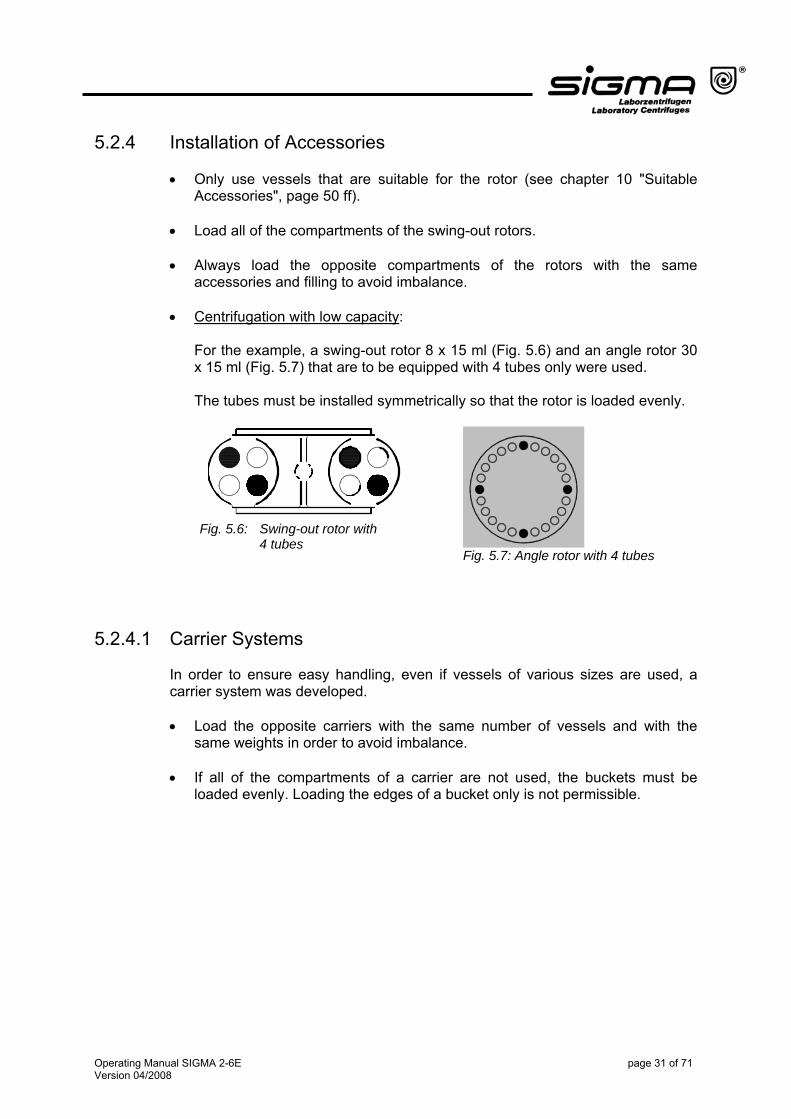
• Centrifugation with low capacity:
For the example, a swing-out rotor 8 x 15 ml (Fig. 5.6) and an angle rotor 30 x 15 ml (Fig. 5.7) that are to be equipped with 4 tubes only were used. The tubes must be installed symmetrically so that the rotor is loaded evenly.
Fig. 5.6: Swing-out rotor with 4 tubes
Fig. 5.7: Angle rotor with 4 tubes
5.2.4.1 Carrier Systems In order to ensure easy handling, even if vessels of various sizes are used, a carrier system was developed. • Load the opposite carriers with the same number of vessels and with the
same weights in order to avoid imbalance.
• If all of the compartments of a carrier are not used, the buckets must be loaded evenly. Loading the edges of a bucket only is not permissible.
Operating Manual SIGMA 2-6E page 31 of 71 Version 04/2008
5.2.4.2 Tubes
• Load the tubes outside of the centrifuge. Liquids in the buckets or multiple carriers cause corrosion.
• Fill the tubes carefully and arrange them according to their weight.
Imbalances result in the excessive wear of the bearings.
• In high-speed angle rotors, the vessels must be filled up to their useful volume (= the volume stated for the vessel). If the vessels are only partially filled, they will deform. This may result in leaks at the seals that may become loose.
• When using glass tubes, please refer to the information provided by the
manufacturer concerning the maximum speed for glass tubes.
Attention! • Please observe the instructions on safety and hazards in chapter 2,
page 16!
5.2.5 Service Life of Rotors and Accessories The rotors and accessories have a limited service life. • Please perform regular checks (at least once per month) for safety reasons! • Pay special attention to changes, such as corrosion, cracks, material
abrasion etc. • After 10 years, they must be inspected by the manufacturer. • After 50,000 cycles, the rotor must be scrapped for reasons of safety. • If other data concerning the service life are engraved on the rotor or
bucket, these data shall apply accordingly!
Operating Manual SIGMA 2-6E page 32 of 71 Version 04/2008
5.2.6 Starting the Centrifuge
The centrifuge is ready for operation when the start key is illuminated. • Press the start key in order to start a centrifugation run.
5.2.7 Interrupting a Centrifugation Run
• Press the stop key in order to interrupt a centrifugation run.
The centrifugation run will be terminated prematurely.
5.2.7.1 Interrupting a Deceleration Process • Press the start key during a deceleration process in order to interrupt it and to
restart the centrifuge.
5.2.7.2 Softstart and Softstop Function The softstart function is used to extend the acceleration time, whereas the softstop function is used to extend the deceleration time. The current combination is shown on the display. The stop key can be used to cyclically select various combinations: • Press the key once to active the softstart function. • Press the key twice to activate the softstart function and the softstop function. • Press the key three times to active the softstop function alone. • Press the key four times to activate the softstart function and the brakeless
deceleration. The “soft stop” display flashes when the brakeless deceleration is active.
• Press the key five times to activate the “brakeless deceleration” function alone (the “soft stop” display flashes).
• Press the key once more to return to the standard operating mode.
Operating Manual SIGMA 2-6E page 33 of 71 Version 04/2008
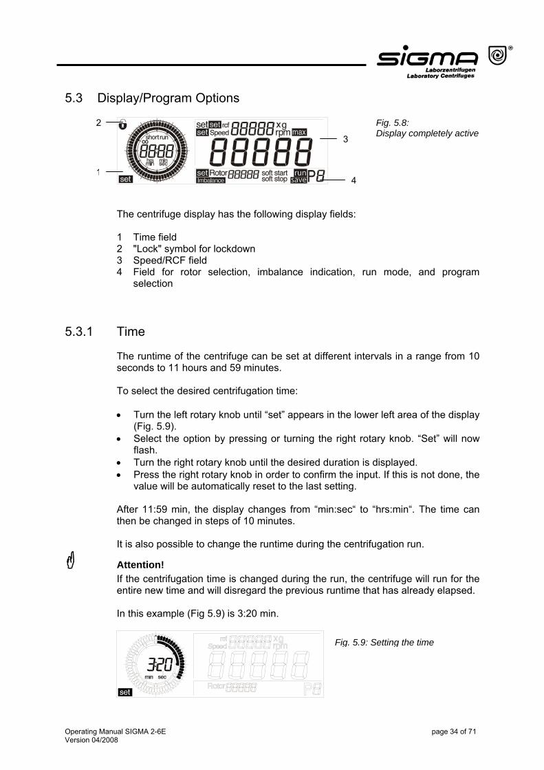
5.3 Display/Program Options
Fig. 5.8: Display completely active
2
1
3
4
The centrifuge display has the following display fields: 1 Time field 2 "Lock" symbol for lockdown 3 Speed/RCF field 4 Field for rotor selection, imbalance indication, run mode, and program
selection
5.3.1 Time The runtime of the centrifuge can be set at different intervals in a range from 10 seconds to 11 hours and 59 minutes. To select the desired centrifugation time: • Turn the left rotary knob until “set” appears in the lower left area of the display
(Fig. 5.9). • Select the option by pressing or turning the right rotary knob. “Set” will now
flash. • Turn the right rotary knob until the desired duration is displayed. • Press the right rotary knob in order to confirm the input. If this is not done, the
value will be automatically reset to the last setting. After 11:59 min, the display changes from “min:sec“ to “hrs:min“. The time can then be changed in steps of 10 minutes. It is also possible to change the runtime during the centrifugation run.
Attention! If the centrifugation time is changed during the run, the centrifuge will run for the entire new time and will disregard the previous runtime that has already elapsed. In this example (Fig 5.9) is 3:20 min.
Fig. 5.9: Setting the time
Operating Manual SIGMA 2-6E page 34 of 71 Version 04/2008
5.3.1.1 Changing the Time Increments In order to change the time in steps of 1 second (instead of in steps of 10 seconds in the min:sec mode) or in steps of 1 minute (instead of in steps of 10 minutes in the hrs:min mode): • Keep the stop key pressed while setting the desired runtime with the right
rotary knob.
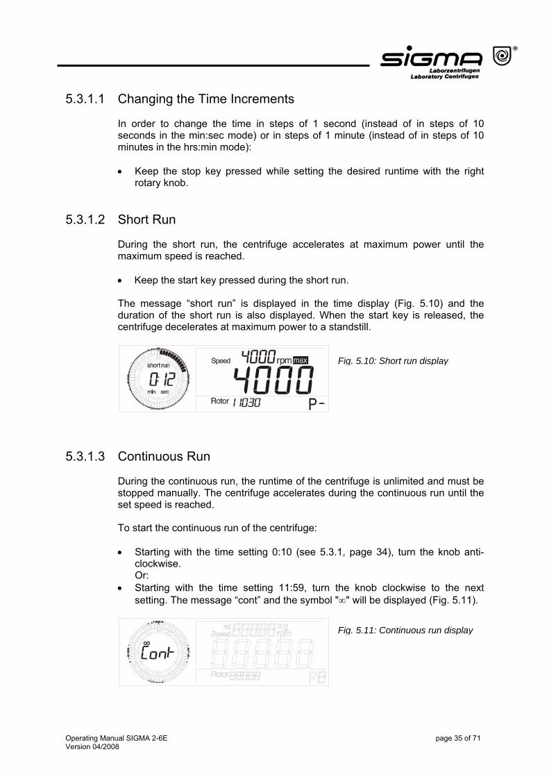
5.3.1.2 Short Run During the short run, the centrifuge accelerates at maximum power until the maximum speed is reached. • Keep the start key pressed during the short run. The message “short run” is displayed in the time display (Fig. 5.10) and the duration of the short run is also displayed. When the start key is released, the centrifuge decelerates at maximum power to a standstill.
Fig. 5.10: Short run display
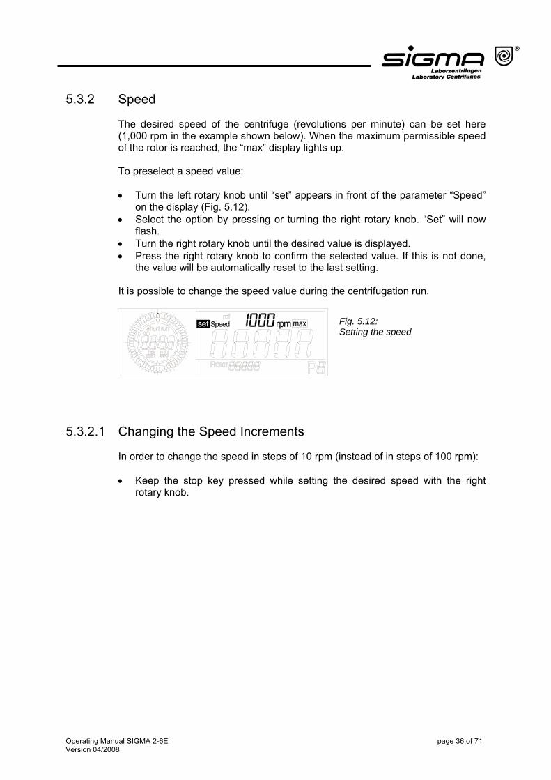
5.3.1.3 Continuous Run During the continuous run, the runtime of the centrifuge is unlimited and must be stopped manually. The centrifuge accelerates during the continuous run until the set speed is reached. To start the continuous run of the centrifuge: • Starting with the time setting 0:10 (see 5.3.1, page 34), turn the knob anti-
clockwise. Or:
• Starting with the time setting 11:59, turn the knob clockwise to the next setting. The message “cont” and the symbol "∞" will be displayed (Fig. 5.11).
Fig. 5.11: Continuous run display
Operating Manual SIGMA 2-6E page 35 of 71 Version 04/2008
5.3.2 Speed The desired speed of the centrifuge (revolutions per minute) can be set here (1,000 rpm in the example shown below). When the maximum permissible speed of the rotor is reached, the “max” display lights up. To preselect a speed value: • Turn the left rotary knob until “set” appears in front of the parameter “Speed”
on the display (Fig. 5.12). • Select the option by pressing or turning the right rotary knob. “Set” will now
flash. • Turn the right rotary knob until the desired value is displayed. • Press the right rotary knob to confirm the selected value. If this is not done,
the value will be automatically reset to the last setting. It is possible to change the speed value during the centrifugation run.
Fig. 5.12: Setting the speed
5.3.2.1 Changing the Speed Increments In order to change the speed in steps of 10 rpm (instead of in steps of 100 rpm): • Keep the stop key pressed while setting the desired speed with the right
rotary knob.
Operating Manual SIGMA 2-6E page 36 of 71 Version 04/2008
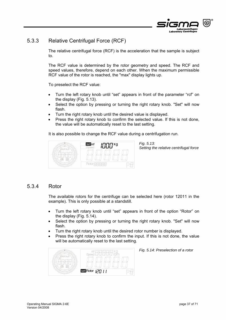
5.3.3 Relative Centrifugal Force (RCF) The relative centrifugal force (RCF) is the acceleration that the sample is subject to. The RCF value is determined by the rotor geometry and speed. The RCF and speed values, therefore, depend on each other. When the maximum permissible RCF value of the rotor is reached, the "max" display lights up. To preselect the RCF value: • Turn the left rotary knob until “set” appears in front of the parameter “rcf” on
the display (Fig. 5.13). • Select the option by pressing or turning the right rotary knob. "Set" will now
flash. • Turn the right rotary knob until the desired value is displayed. • Press the right rotary knob to confirm the selected value. If this is not done,
the value will be automatically reset to the last setting. It is also possible to change the RCF value during a centrifugation run.
5.3.4 Rotor
Fig. 5.13: Setting the relative centrifugal force
The available rotors for the centrifuge can be selected here (rotor 12011 in the example). This is only possible at a standstill. • Turn the left rotary knob until “set” appears in front of the option “Rotor” on
the display (Fig. 5.14). • Select the option by pressing or turning the right rotary knob. "Set" will now
flash. • Turn the right rotary knob until the desired rotor number is displayed. • Press the right rotary knob to confirm the input. If this is not done, the value
will be automatically reset to the last setting.
Fig. 5.14: Preselection of a rotor
Operating Manual SIGMA 2-6E page 37 of 71 Version 04/2008
5.3.5 Program The program is used to save or load certain recurrent settings of the centrifuge. This saves time and prevents typing errors. Ten different programs (0-9) can be saved and called up. This is only possible at a standstill.
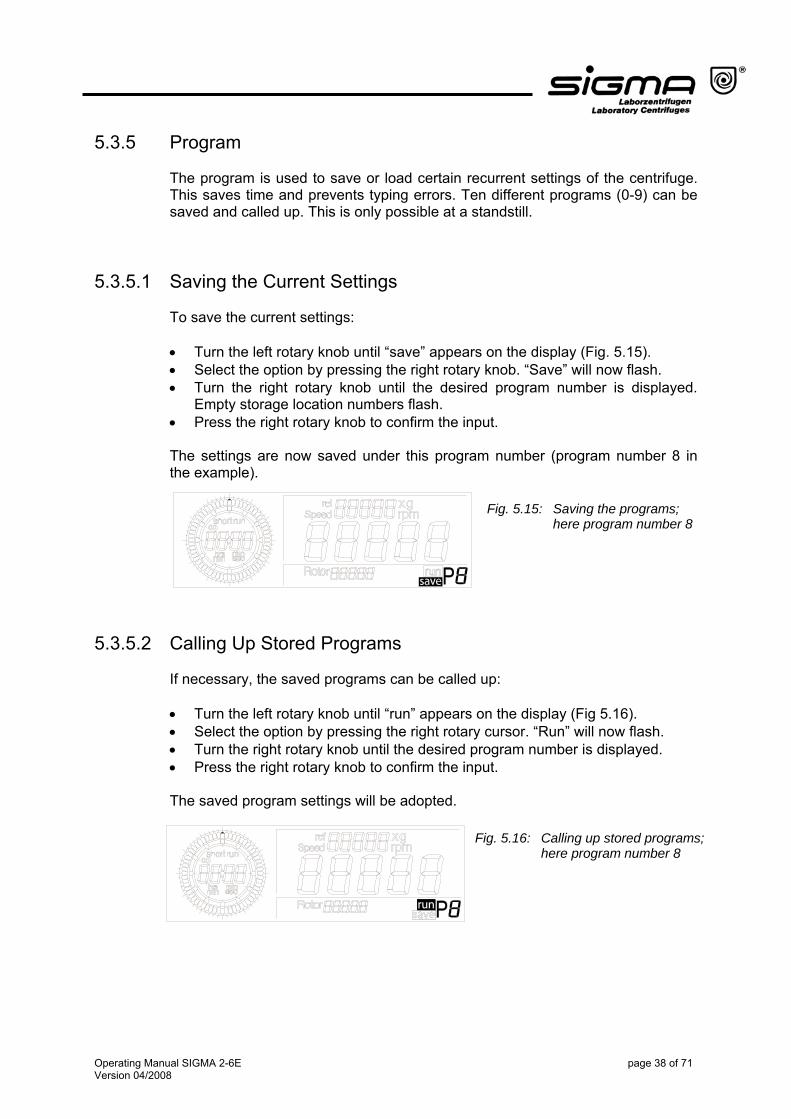
5.3.5.1 Saving the Current Settings To save the current settings: • Turn the left rotary knob until “save” appears on the display (Fig. 5.15). • Select the option by pressing the right rotary knob. “Save” will now flash. • Turn the right rotary knob until the desired program number is displayed.
Empty storage location numbers flash. • Press the right rotary knob to confirm the input. The settings are now saved under this program number (program number 8 in the example).
Fig. 5.15: Saving the programs; here program number 8
5.3.5.2 Calling Up Stored Programs If necessary, the saved programs can be called up: • Turn the left rotary knob until “run” appears on the display (Fig 5.16). • Select the option by pressing the right rotary cursor. “Run” will now flash. • Turn the right rotary knob until the desired program number is displayed. • Press the right rotary knob to confirm the input. The saved program settings will be adopted.
Fig. 5.16: Calling up stored programs; here program number 8
Operating Manual SIGMA 2-6E page 38 of 71 Version 04/2008
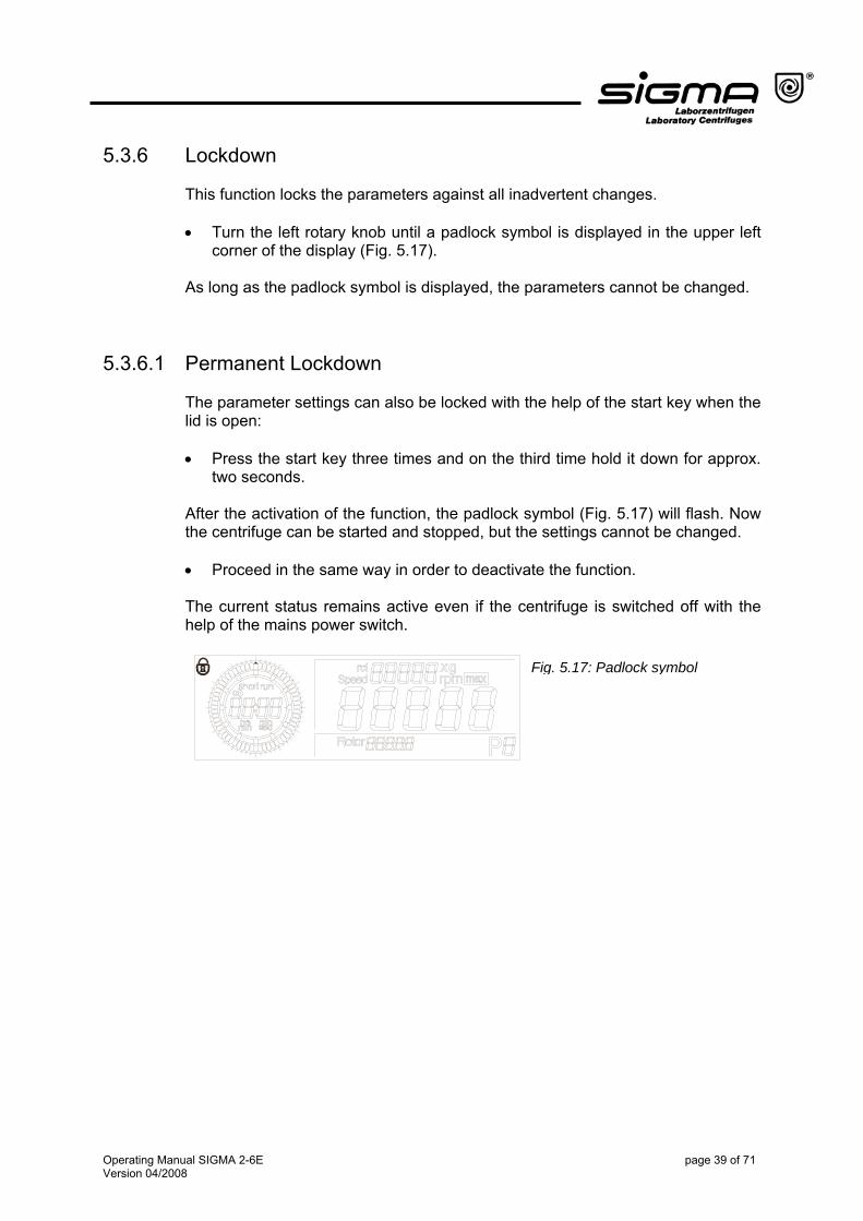
5.3.6 Lockdown This function locks the parameters against all inadvertent changes. • Turn the left rotary knob until a padlock symbol is displayed in the upper left
corner of the display (Fig. 5.17). As long as the padlock symbol is displayed, the parameters cannot be changed.
5.3.6.1 Permanent Lockdown The parameter settings can also be locked with the help of the start key when the lid is open: • Press the start key three times and on the third time hold it down for approx.
two seconds. After the activation of the function, the padlock symbol (Fig. 5.17) will flash. Now the centrifuge can be started and stopped, but the settings cannot be changed. • Proceed in the same way in order to deactivate the function. The current status remains active even if the centrifuge is switched off with the help of the mains power switch. Fig. 5.17: Padlock symbol
Operating Manual SIGMA 2-6E page 39 of 71 Version 04/2008

5.3.7 Activating/Deactivating the Automatic Lid Opening Function
The Auto-Lid-Open function must be activated so that the lid opens automatically at the end of the operation: • Press the lid key three times when the lid is open and on the third time hold it
down for approx. two seconds. • Proceed in the same way in order to deactivate the function. After every change, the current status of the setting is displayed in the form of a message running over the display ("Auto-Lid-Open on" or "off").
5.3.8 Activating/Deactivating the Sound Signal If this function is active, a sound signal can be heard at the end of the operation as well as in the event of an error message or imbalance. • Press the lid key five times and on the fifth time hold it down for approx. two
seconds. • Proceed in the same way in order to deactivate the function. After every change, the current status of the setting is displayed in the form of a message running in the display ("Buzzer on" or "off").
Operating Manual SIGMA 2-6E page 40 of 71 Version 04/2008
6 Malfunctions and Error Correction
6.1 Error Mode Malfunctions are indicated by error messages with a number in the speed display. If the sound signal is activated, it sounds when the error message is displayed (see 5.3.8 "Activating/Deactivating the Sound Signal", page 40).
6.2 Error Correction
• Eliminate the source of the problem (see 6.2.1 to 6.2.6, page 41ff). • Acknowledge the error messages with the lid key.
6.2.1 No Indication on the Display
− Voltage in the socket? • Check fuse in the mains supply.
− Power cord plugged in and line voltage present?
• Plug in power cord correctly.
− Fuse OK?
• Replace fuse (see fig. 5.4 "name plate", page 26).
− Mains power switch on? • Switch on power.
− Lid closed? • Close lid (see 6.2.4 “Lid cannot be opened", page 42).
6.2.2 Centrifuge cannot be started
− Start key LED not illuminated: • Power off/on. If the error occurs again,
call the service.
− Lid key LED flashes: • Open and close the lid again. If error occurs again although both locks are locked, call the service.
6.2.3 Centrifuge decelerates during Operation
− There was a brief mains power failure (at least 2 sec), error message 61
− Centrifuge displays an error from 1 to 11 after powering on.
• Press the start key in order to restart the centrifuge.
• Power off/on (see 6.2.6 "Error Codes", page 43). If the error occurs again, call the service.
Operating Manual SIGMA 2-6E page 41 of 71 Version 04/2008
6.2.4 Lid cannot be opened − When first trying to open the lid,
the locks are not released. Lid key LED flashes.
• Close the lid again. Press down both sides of the lid until the locks audibly lock. Open the lid again. If the error occurs again, unlock the lid manually (see 6.2.5 "Emergency lid release", page 42) and call the service.
− The lid cannot be opened, although both locks have audibly unlocked.
• Check/clean the lid seal. Apply talcum powder to the seal to avoid sticking.
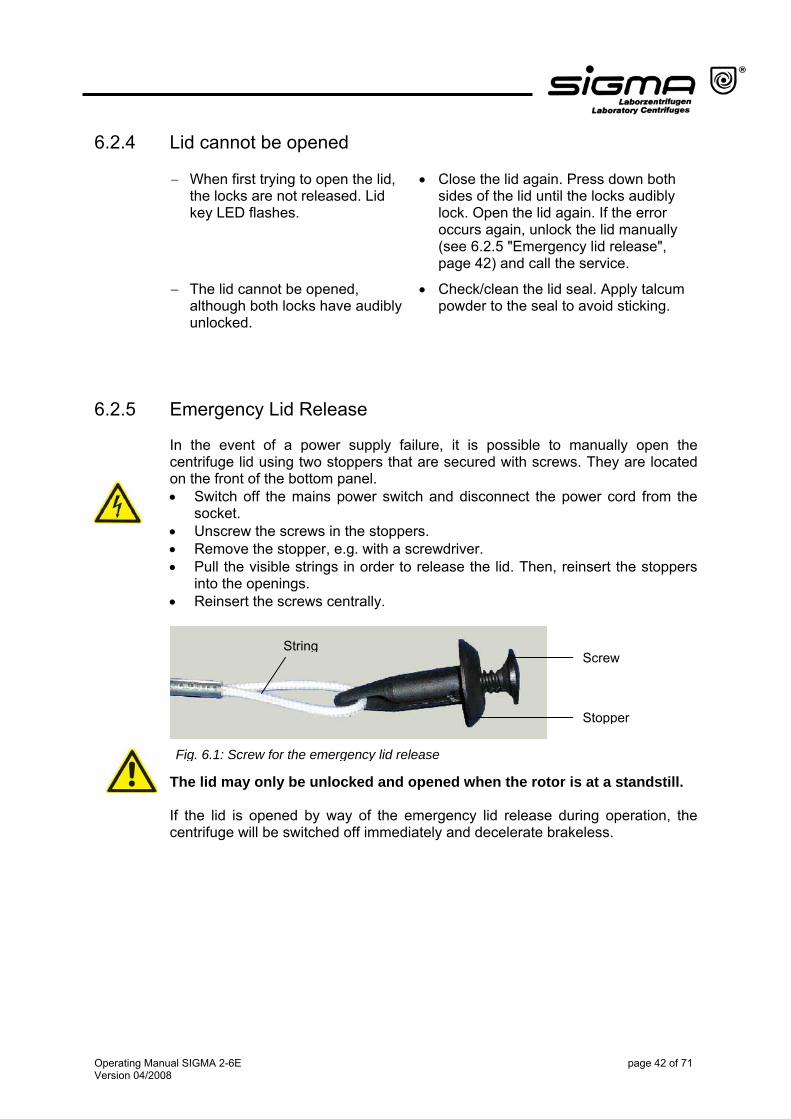
6.2.5 Emergency Lid Release
In the event of a power supply failure, it is possible to manually open the centrifuge lid using two stoppers that are secured with screws. They are located on the front of the bottom panel. • Switch off the mains power switch and disconnect the power cord from the
socket. • Unscrew the screws in the stoppers. • Remove the stopper, e.g. with a screwdriver. • Pull the visible strings in order to release the lid. Then, reinsert the stoppers
into the openings. • Reinsert the screws centrally.
The lid may only be unlocked and opened when the rotor is at a standstill. If the lid is opened by way of the emergency lid release during operation, the centrifuge will be switched off immediately and decelerate brakeless.
Screw
Stopper
String
Fig. 6.1: Screw for the emergency lid release
Operating Manual SIGMA 2-6E page 42 of 71 Version 04/2008
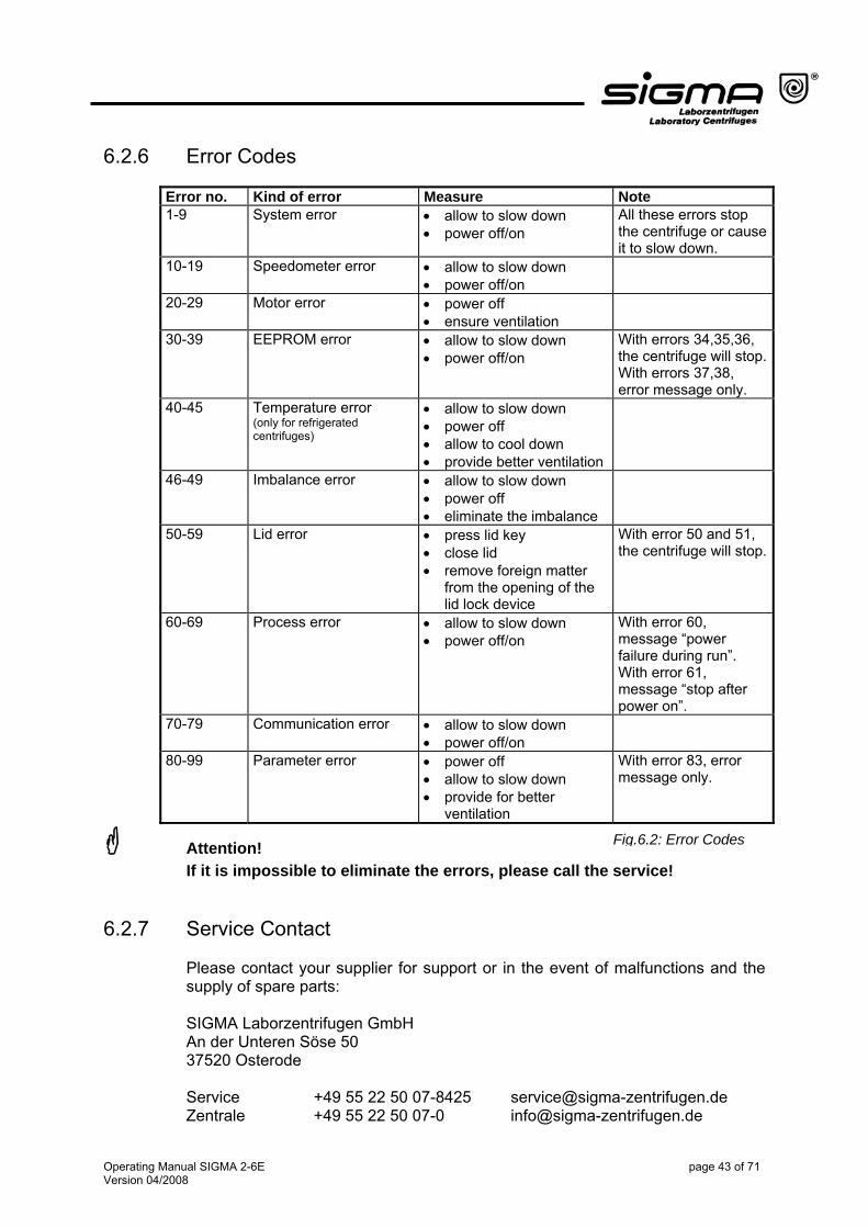
6.2.6 Error Codes
Error no. Kind of error Measure Note 1-9 System error • allow to slow down
• power off/on All these errors stop the centrifuge or cause it to slow down.
10-19 Speedometer error • allow to slow down • power off/on
20-29 Motor error • power off • ensure ventilation
30-39 EEPROM error • allow to slow down • power off/on
With errors 34,35,36, the centrifuge will stop. With errors 37,38, error message only.
40-45 Temperature error (only for refrigerated centrifuges)
• allow to slow down • power off
• allow to cool down • provide better ventilation
46-49 Imbalance error • allow to slow down • power off • eliminate the imbalance
50-59 Lid error • press lid key • close lid • remove foreign matter
from the opening of the lid lock device
With error 50 and 51, the centrifuge will stop.
60-69 Process error With error 60, message “power failure during run”. With error 61, message “stop after power on”.
• allow to slow down • power off/on
70-79 Communication error • allow to slow down • power off/on
80-99 Parameter error With error 83, error message only.
• power off • allow to slow down • provide for better
ventilation
Attention! Fig.6.2: Error Codes
If it is impossible to eliminate the errors, please call the service! 6.2.7 Service Contact
Please contact your supplier for support or in the event of malfunctions and the supply of spare parts: SIGMA Laborzentrifugen GmbH An der Unteren Söse 50 37520 Osterode Service +49 55 22 50 07-8425 [email protected] Zentrale +49 55 22 50 07-0 [email protected]
Operating Manual SIGMA 2-6E page 43 of 71 Version 04/2008
7 Care and Maintenance
7.1 Cleaning and Care The centrifuge, rotor, and accessories are subject to high mechanical stress. Thorough maintenance care performed by the user extends the service life and prevents premature failure.
Attention! If corrosion or other damage occurs due to improper care, the manufacturer cannot be held liable or subject to any warranty claims. • Use soap water or other water-soluble, mild cleaning agents (pH value
between 6 and 8). • Avoid corrosive and aggressive substances. • Do not use alkaline solutions or solvents. • Do not use agents with abrasive particles. • Do not expose the centrifuge and rotors to intensive UV radiation or thermal
stress (e.g. by heat generators).
7.1.1 Centrifuge
• Disconnect the power cord from the socket before cleaning. • Carefully remove all liquids, including water and particularly all the solvents,
acids, and alkaline solutions from the centrifuge chamber using a cloth in order to avoid damage to the motor bearings.
• If the centrifuge has been contaminated with toxic, radioactive, or pathogenic substances, clean the centrifuge chamber immediately with a suitable decontamination agent (depending on the type of contamination). Take suitable precautions for your own safety if there is a risk of toxic, radioactive, or pathogenic contamination.
• Grease the motor shaft slightly after cleaning (grease for load-bearing bolts
part no. 70284). • Open the centrifuge when it is not in use so moisture can evaporate. This
prevents the increased wear of the motor bearings.
Operating Manual SIGMA 2-6E page 44 of 71 Version 04/2008
7.1.2 Accessories For the care of the accessories, special safety measures must be considered as these are measures that will ensure operational safety at the same time. • Immediately rinse off the rotor, buckets, or accessories if any liquids that may
cause corrosion come into contact with them. • Clean the accessories outside the centrifuge once a week or preferably after
each use. Rubber cushions should be removed. • If the rotors or accessories have been contaminated with toxic, radioactive, or
pathogenic substances, clean them immediately with a suitable decontamination agent (depending on the type of contamination). Take suitable precautions for your own safety if there is a risk of toxic, radioactive, or pathogenic contamination.
• Dry the accessories with a soft cloth or in a drying chamber at approx. 50°C.
7.1.2.1 Plastic Accessories
• If solvents, acids, or alkaline solutions have been used, clean the plastic
accessories thoroughly. The chemical resistance of plastic decreases with rising temperatures (e.g. during drying).
7.1.2.2 Aluminum Accessories Especially aluminum parts are susceptible to corrosion. • Acid-containing cleaning agents and alkaline cleaning agents must be
avoided (see 7.1 "Cleaning and Care", page 44). • Grease aluminum parts at least once a week with slushing oil (part no.
70104). This essentially increases their service life and reduces susceptibility to corrosion.
Operating Manual SIGMA 2-6E page 45 of 71 Version 04/2008
7.1.3 Rotor, Buckets, and Multiple Carriers Chemical reactions as well as stress-corrosion (combination of oscillating pressure and chemical reaction) can affect or destroy the metals. Barely detectable cracks on the surface can expand and weaken the material without any visible signs. • Check the material regularly (at least once a month) for
− cracks − visible damage of the surface − pressure marks − signs of corrosion − other changes.
• Check the bores of the rotors and multiple carriers. • Replace any damaged components immediately for your own safety.
• Protect the rotors, lid seals, and rubber cushions (if included) at least once
per week with the supplied slushing oil (part no. 70104). • Grease the rotor tie-down screw with grease for load-bearing bolts (part no.
70284).
7.1.4 Load-bearing bolts
Only greased load-bearing bolts ensure the even swinging of the buckets, and therefore, the quiet run of the centrifuge. Ungreased bolts can lead to a system shut-down due to imbalances. • Grease the load-bearing bolts of the rotor after each cleaning slightly with
grease for load-bearing bolts (part no. 70284).
Operating Manual SIGMA 2-6E page 46 of 71 Version 04/2008
7.1.5 Glass Breakage • Glass particles will damage the surface coating (e.g. Eloxal) of the buckets,
which will then lead to corrosion. • Glass particles in the rubber cushions of the buckets will cause glass
breakage again.
• Glass particles on the pivot bearing of the load-bearing bolts prevent the buckets and carriers from swinging evenly, which will cause an imbalance.
• Glass particles in the centrifuge chamber will cause metal abrasion due to the
strong air circulation. This metal dust will not only pollute the centrifuge chamber, rotor, and materials to be centrifuged but also damage the surfaces of the accessories, rotors, and centrifuge chamber.
In the case of glass breakage, immediately remove all glass particles (e.g. with a vacuum cleaner). Replace the rubber cushions since even thorough cleaning will not remove all glass particles. In order to completely remove the glass particles and the metal dust from the rotor chamber: • Grease the upper third of the centrifuge chamber with e.g. Vaseline. • Then, let the rotor rotate for a few minutes at a moderate speed (approx .
2,000 rpm). The glass and metal particles will now collect at the greased part and can easily be removed with a cloth together with the grease.
• Remove the grease with glass and metal particles with a cloth.
• If necessary, repeat this procedure.
7.2 Sterilization and Disinfection of the Rotor Chamber and Accessories
• Use commercially-available disinfectants such as, for example, Sagrotan®,
Buraton®, or Terralin® (available at chemist’s shops or drugstores). • The centrifuges and the accessories consist of various materials. A possible
incompatibility must be considered. • Before using cleaning or decontamination agents that were not
recommended by us, contact the manufacturer to ensure that such a procedure will not damage the centrifuge.
• For autoclaving, consider the continuous heat resistance of the individual materials (see 7.2.1 “Autoclaving“, page 48). Please contact us if you have any queries (see 6.2.7 "Service Contact", page 43).
If dangerous materials (e.g. infectious and pathogenic substances) are used, the centrifuge and accessories must be disinfected.
Operating Manual SIGMA 2-6E page 47 of 71 Version 04/2008
7.2.1 Autoclaving The service life of the accessories essentially depends on the frequency of autoclaving and use. • Replace the accessories immediately when the parts show changes in color
or structure or in the occurrence of leaks etc. • During autoclaving, the caps of the tubes must not be screwed on in order to
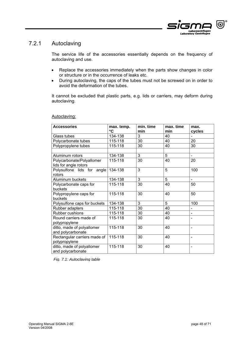
avoid the deformation of the tubes. It cannot be excluded that plastic parts, e.g. lids or carriers, may deform during autoclaving. Autoclaving: Accessories max. temp.
°C min. time min
max. time min
max. cycles
Glass tubes 134-138 3 40 - Polycarbonate tubes 115-118 30 40 20 Polypropylene tubes 115-118 30 40 30 Aluminum rotors 134-138 3 5 - Polycarbonate/Polyallomer lids for angle rotors
115-118 30 40 20
Polysulfone lids for angle rotors
134-138 3 5 100
Aluminum buckets 134-138 3 5 - Polycarbonate caps for buckets
115-118 30 40 50
Polypropylene caps for buckets
115-118 30 40 50
Polysulfone caps for buckets 134-138 3 5 100 Rubber adapters 115-118 30 40 - Rubber cushions 115-118 30 40 - Round carriers made of polypropylene
115-118 30 40 -
ditto, made of polyallomer and polycarbonate
115-118 30 40 -
Rectangular carriers made of polypropylene
115-118 30 40 -
ditto, made of polyallomer and polycarbonate
115-118 30 40 -
Fig. 7.1: Autoclaving table
Operating Manual SIGMA 2-6E page 48 of 71 Version 04/2008
8 Disposal
8.1 Disposal of the Centrifuge In accordance with the directive 2002/96/EC, SIGMA centrifuges are marked with the symbol shown to the left. This symbol means that it is not permissible to dispose of the unit among household trash. • You can return these centrifuges free of cost to SIGMA Laborzentrifugen
GmbH. • Please ensure that the unit is decontaminated.
• Please fill in the enclosed declaration of decontamination.
• Please comply with any other applicable local rules and regulations.
8.2 Disposal of the Packaging • Use the packaging to return the centrifuge for disposal. Or: • Dispose of the packaging, after having separated the individual materials. • Please comply with all local rules and regulations.
9 Warranty and Liability
The warranty and liability are subject to our "General Conditions" that were distributed to the operator upon the conclusion of the contract. Warranty and liability claims are excluded if they are due to: • Improper use • Non-compliance with the safety instructions and hazard warnings in the
operating manual
• Force majeure
Operating Manual SIGMA 2-6E page 49 of 71 Version 04/2008
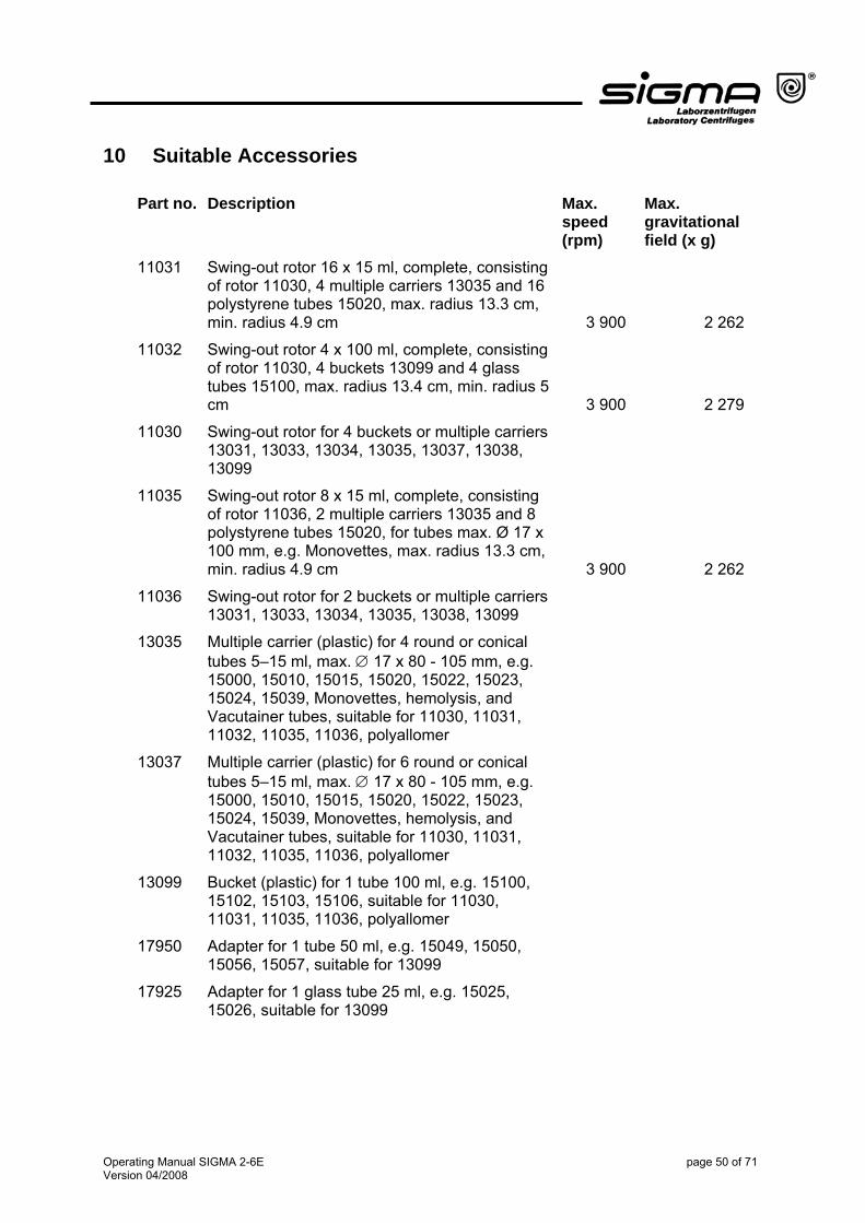
10 Suitable Accessories
Part no. Description Max. speed (rpm)
Max. gravitational field (x g)
11031 Swing-out rotor 16 x 15 ml, complete, consisting of rotor 11030, 4 multiple carriers 13035 and 16 polystyrene tubes 15020, max. radius 13.3 cm, min. radius 4.9 cm
3 900 2 262
11032 Swing-out rotor 4 x 100 ml, complete, consisting of rotor 11030, 4 buckets 13099 and 4 glass tubes 15100, max. radius 13.4 cm, min. radius 5 cm
3 900 2 279
11030 Swing-out rotor for 4 buckets or multiple carriers 13031, 13033, 13034, 13035, 13037, 13038, 13099
11035 Swing-out rotor 8 x 15 ml, complete, consisting of rotor 11036, 2 multiple carriers 13035 and 8 polystyrene tubes 15020, for tubes max. Ø 17 x 100 mm, e.g. Monovettes, max. radius 13.3 cm, min. radius 4.9 cm
3 900 2 262
11036 Swing-out rotor for 2 buckets or multiple carriers 13031, 13033, 13034, 13035, 13038, 13099
13035 Multiple carrier (plastic) for 4 round or conical tubes 5–15 ml, max. ∅ 17 x 80 - 105 mm, e.g. 15000, 15010, 15015, 15020, 15022, 15023, 15024, 15039, Monovettes, hemolysis, and Vacutainer tubes, suitable for 11030, 11031, 11032, 11035, 11036, polyallomer
13037 Multiple carrier (plastic) for 6 round or conical tubes 5–15 ml, max. ∅ 17 x 80 - 105 mm, e.g. 15000, 15010, 15015, 15020, 15022, 15023, 15024, 15039, Monovettes, hemolysis, and Vacutainer tubes, suitable for 11030, 11031, 11032, 11035, 11036, polyallomer
13099 Bucket (plastic) for 1 tube 100 ml, e.g. 15100, 15102, 15103, 15106, suitable for 11030, 11031, 11035, 11036, polyallomer
17950 Adapter for 1 tube 50 ml, e.g. 15049, 15050, 15056, 15057, suitable for 13099
17925 Adapter for 1 glass tube 25 ml, e.g. 15025, 15026, suitable for 13099
Operating Manual SIGMA 2-6E page 50 of 71 Version 04/2008
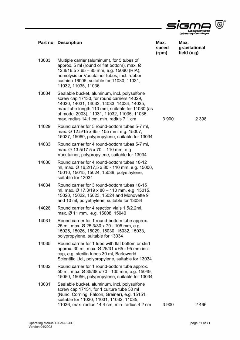
Part no. Description Max. speed (rpm)
Max. gravitational field (x g)
13033 Multiple carrier (aluminum), for 5 tubes of approx. 5 ml (round or flat bottom), max. Ø 12.8/16.5 x 65 – 85 mm, e.g. 15060 (RIA), hemolysis or Vacutainer tubes, incl. rubber cushion 16005, suitable for 11030, 11031, 11032, 11035, 11036
13034 Sealable bucket, aluminum, incl. polysulfone screw cap 17130, for round carriers 14029, 14030, 14031, 14032, 14033, 14034, 14035, max. tube length 110 mm, suitable for 11030 (as of model 2003), 11031, 11032, 11035, 11036, max. radius 14.1 cm, min. radius 7.1 cm
3 900 2 398
14029 Round carrier for 5 round-bottom tubes 5-7 ml, max. Ø 12.5/15 x 65 - 105 mm, e.g. 15007, 15027, 15060, polypropylene, suitable for 13034
14033 Round carrier for 4 round-bottom tubes 5-7 ml, max. ∅ 13.5/17.5 x 70 – 110 mm, e.g. Vacutainer, polypropylene, suitable for 13034
14030 Round carrier for 4 round-bottom tubes 10-12 ml, max. Ø 16,2/17,5 x 80 - 110 mm, e.g. 15000, 15010, 15015, 15024, 15039, polyethylene, suitable for 13034
14034 Round carrier for 3 round-bottom tubes 10-15 ml, max. Ø 17.3/19 x 80 – 110 mm, e.g. 15015, 15020, 15022, 15023, 15024 and Monovette 9 and 10 ml, polyethylene, suitable for 13034
14028 Round carrier for 4 reaction vials 1.5/2.2ml, max. Ø 11 mm, e.g. 15008, 15040
14031 Round carrier for 1 round-bottom tube approx. 25 ml, max. Ø 25.3/30 x 70 - 105 mm, e.g. 15025, 15026, 15029, 15030, 15032, 15033, polypropylene, suitable for 13034
14035 Round carrier for 1 tube with flat bottom or skirt approx. 30 ml, max. Ø 25/31 x 65 - 95 mm incl. cap, e.g. sterilin tubes 30 ml, Barloworld Scientific Ltd., polypropylene, suitable for 13034
14032 Round carrier for 1 round-bottom tube approx. 50 ml, max. Ø 35/38 x 70 - 105 mm, e.g. 15049, 15050, 15056, polypropylene, suitable for 13034
13031 Sealable bucket, aluminum, incl. polysulfone screw cap 17151, for 1 culture tube 50 ml (Nunc, Corning, Falcon, Greiner), e.g. 15151, suitable for 11030, 11031, 11032, 11035, 11036, max. radius 14.4 cm, min. radius 4.2 cm
3 900 2 466
Operating Manual SIGMA 2-6E page 51 of 71 Version 04/2008
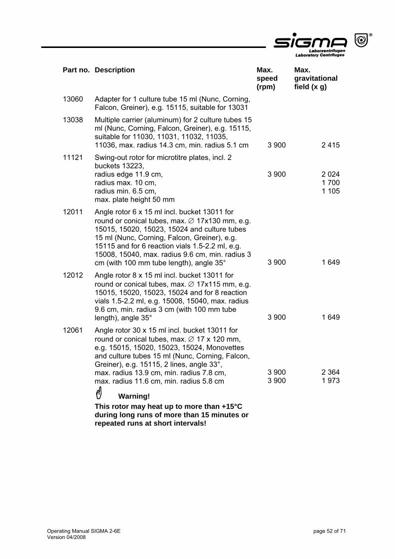
Part no. Description Max. speed (rpm)
Max. gravitational field (x g)
13060 Adapter for 1 culture tube 15 ml (Nunc, Corning, Falcon, Greiner), e.g. 15115, suitable for 13031
13038 Multiple carrier (aluminum) for 2 culture tubes 15 ml (Nunc, Corning, Falcon, Greiner), e.g. 15115, suitable for 11030, 11031, 11032, 11035, 11036, max. radius 14.3 cm, min. radius 5.1 cm
3 900 2 415
11121 Swing-out rotor for microtitre plates, incl. 2 buckets 13223, radius edge 11.9 cm, radius max. 10 cm, radius min. 6.5 cm, max. plate height 50 mm
3 900 2 0241 7001 105
12011 Angle rotor 6 x 15 ml incl. bucket 13011 for round or conical tubes, max. ∅ 17x130 mm, e.g. 15015, 15020, 15023, 15024 and culture tubes 15 ml (Nunc, Corning, Falcon, Greiner), e.g. 15115 and for 6 reaction vials 1.5-2.2 ml, e.g. 15008, 15040, max. radius 9.6 cm, min. radius 3 cm (with 100 mm tube length), angle 35°
3 900 1 649
Angle rotor 8 x 15 ml incl. bucket 13011 for round or conical tubes, max. ∅ 17x115 mm, e.g. 15015, 15020, 15023, 15024 and for 8 reaction vials 1.5-2.2 ml, e.g. 15008, 15040, max. radius 9.6 cm, min. radius 3 cm (with 100 mm tube length), angle 35°
3 900
12012
1 649
12061 Angle rotor 30 x 15 ml incl. bucket 13011 for round or conical tubes, max. ∅ 17 x 120 mm, e.g. 15015, 15020, 15023, 15024, Monovettes and culture tubes 15 ml (Nunc, Corning, Falcon, Greiner), e.g. 15115, 2 lines, angle 33°, max. radius 13.9 cm, min. radius 7.8 cm, max. radius 11.6 cm, min. radius 5.8 cm
Warning! This rotor may heat up to more than +15°C during long runs of more than 15 minutes or repeated runs at short intervals!
3 900 3 900
2 3641 973
Operating Manual SIGMA 2-6E page 52 of 71 Version 04/2008
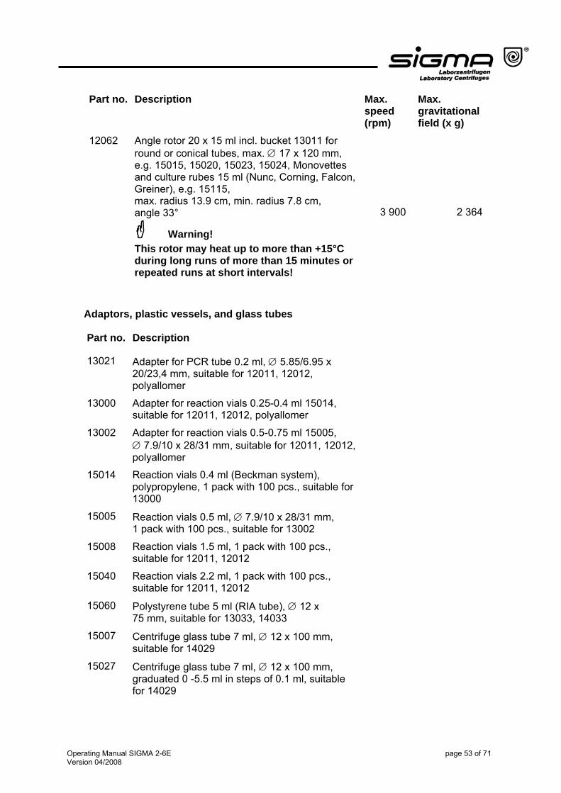
Part no. Description Max. speed (rpm)
Max. gravitational field (x g)
3 900
12062 Angle rotor 20 x 15 ml incl. bucket 13011 for round or conical tubes, max. ∅ 17 x 120 mm, e.g. 15015, 15020, 15023, 15024, Monovettes and culture rubes 15 ml (Nunc, Corning, Falcon, Greiner), e.g. 15115, max. radius 13.9 cm, min. radius 7.8 cm, angle 33°
Warning! This rotor may heat up to more than +15°C during long runs of more than 15 minutes or repeated runs at short intervals!
2 364
Adaptors, plastic vessels, and glass tubes Part no. Description
13021 Adapter for PCR tube 0.2 ml, ∅ 5.85/6.95 x 20/23,4 mm, suitable for 12011, 12012, polyallomer
13000 Adapter for reaction vials 0.25-0.4 ml 15014, suitable for 12011, 12012, polyallomer
13002 Adapter for reaction vials 0.5-0.75 ml 15005, ∅ 7.9/10 x 28/31 mm, suitable for 12011, 12012, polyallomer
15014 Reaction vials 0.4 ml (Beckman system), polypropylene, 1 pack with 100 pcs., suitable for 13000
15005 Reaction vials 0.5 ml, ∅ 7.9/10 x 28/31 mm, 1 pack with 100 pcs., suitable for 13002
15008 Reaction vials 1.5 ml, 1 pack with 100 pcs., suitable for 12011, 12012
15040 Reaction vials 2.2 ml, 1 pack with 100 pcs., suitable for 12011, 12012
15060 Polystyrene tube 5 ml (RIA tube), ∅ 12 x 75 mm, suitable for 13033, 14033
15007 Centrifuge glass tube 7 ml, ∅ 12 x 100 mm, suitable for 14029
15027 Centrifuge glass tube 7 ml, ∅ 12 x 100 mm, graduated 0 -5.5 ml in steps of 0.1 ml, suitable for 14029
Operating Manual SIGMA 2-6E page 53 of 71 Version 04/2008
Part no. Description
15015 Centrifuge glass tube 10-15 ml, ∅ 16 x 100 mm, suitable for 12011, 12012, 12061, 12062, 13035, 13037, 14030
15024 Centrifuge glass tube 10-15 ml, ∅ 16 x 100 mm, graduated 0-10 ml in steps of 0.1 ml, suitable for 12011, 12012, 12061, 12062, 13035, 13037, 14030
15020 Polystyrene tube 15 ml, ∅ 17 x 100 mm, suitable for 11031, 11035, 12011, 12012, 12061, 12062, 13035, 13037, 14034
15021 Polypropylene stopper for 15020, 15023
15023 Polypropylene tube 15 ml, ∅ 17 x 100 mm, suitable for 12011, 12012, 12061, 12062, 13035, 13037, 14034
15025 Centrifuge glass tube 25 ml, ∅ 24 x 100 mm, suitable for 14031, 17925
15026 Centrifuge glass tube 25 ml, ∅ 24 x 100 mm, graduated 5 -25 ml in steps of 1 ml, suitable for 14031, 17925
15050 Centrifuge glass tube 50 ml, ∅ 34 x 100 mm, suitable for 14032, 17950
15056 Centrifuge glass tube 50 ml, ∅ 34 x 100 mm graduated 4 -50 ml in steps of 1 ml, suitable for 14032, 17950
15049 Polycarbonate vessel 50 ml, ∅ 34 x 100 mm, graduated 0 – 50 ml in steps of 1 ml, suitable for 14032, 17950
15100 Centrifuge glass tube 100 ml, ∅ 44 x 100 mm, suitable for 11032, 13099
15106 Centrifuge glass tube 100 ml, ∅ 44 x 100 mm, graduated 1 - 80 ml in steps of 1 ml, suitable for 11032, 13099
15102 Polypropylene tube 120 ml, ∅ 45 x 100 mm, suitable for 13099
15103 Polycarbonate vessel 110 ml, ∅ 45 x 100 mm, graduated 2 – 100 ml in steps of 2 ml, suitable for 13099
15115 Culture tube with screw cap 15 ml, pointed bottom, suitable for 12061, 12062, 13060, polypropylene
15151 Culture tube with screw cap 50 ml, pointed bottom, suitable for 13031, polypropylene
Operating Manual SIGMA 2-6E page 54 of 71 Version 04/2008
Spare parts Part no. Description
13011 Nylon bucket for 1 tube 15 ml, for 12011, 12012, 12061, 12062
17130 Round sealing cap, polysulfone, transparent, for 13034
17151 Round sealing cap, polysulfone, transparent, for 13031
Further accessories available upon request. Maximum speed for tubes: Some tubes, such as centrifuge glass tubes, microtubes, culture tubes, fluoropolymer tubes and especially high-volume tubes can be used in our rotors, buckets, and adapters at higher speeds than their breaking limit. • Always fill the tubes up to their useful volume (= the volume that is stated for
the tube). • Follow the manufacturer’s recommendations.
Operating Manual SIGMA 2-6E page 55 of 71 Version 04/2008
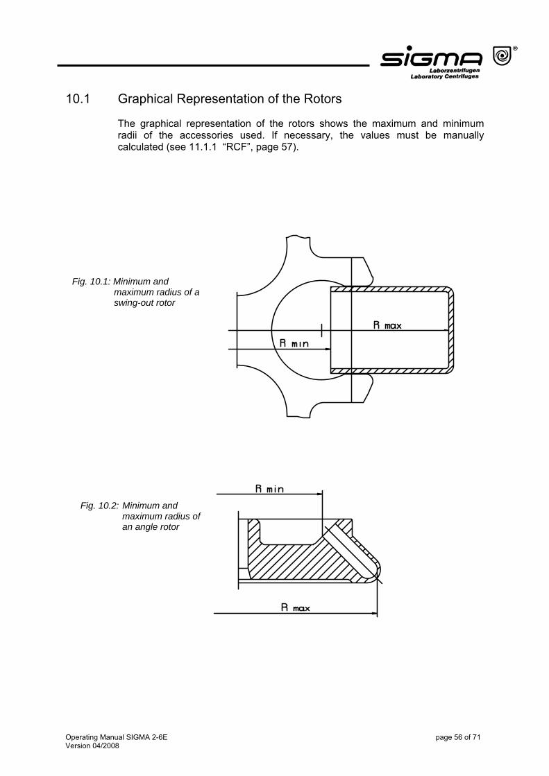
10.1 Graphical Representation of the Rotors The graphical representation of the rotors shows the maximum and minimum radii of the accessories used. If necessary, the values must be manually calculated (see 11.1.1 “RCF”, page 57).
Fig. 10.1: Minimum and maximum radius of a swing-out rotor
Fig. 10.2: Minimum and maximum radius of an angle rotor
Operating Manual SIGMA 2-6E page 56 of 71 Version 04/2008
11 Appendix
11.1 Formulae – Mathematical Relations
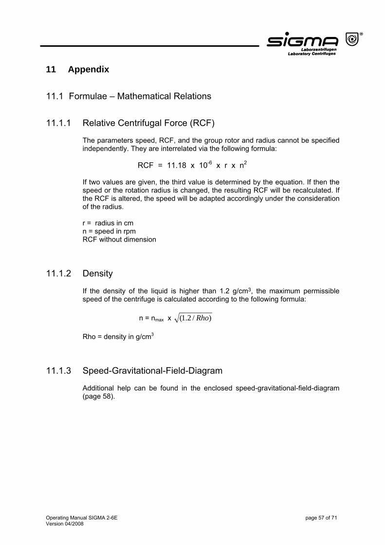
11.1.1 Relative Centrifugal Force (RCF) The parameters speed, RCF, and the group rotor and radius cannot be specified independently. They are interrelated via the following formula: RCF = 11.18 x 10⁻⁶ x r x n2
If two values are given, the third value is determined by the equation. If then the speed or the rotation radius is changed, the resulting RCF will be recalculated. If the RCF is altered, the speed will be adapted accordingly under the consideration of the radius. r = radius in cm n = speed in rpm RCF without dimension
11.1.2 Density If the density of the liquid is higher than 1.2 g/cm3, the maximum permissible speed of the centrifuge is calculated according to the following formula:
n = nmax x )/2.1( Rho Rho = density in g/cm3
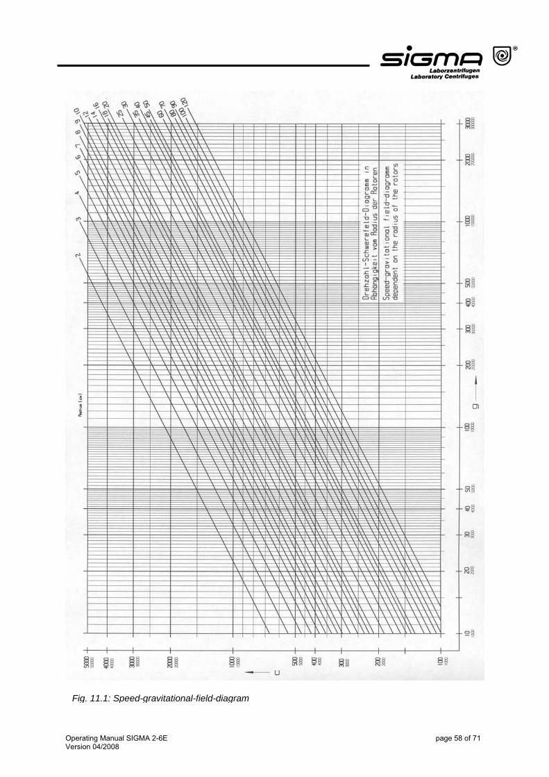
11.1.3 Speed-Gravitational-Field-Diagram
Additional help can be found in the enclosed speed-gravitational-field-diagram (page 58).
Operating Manual SIGMA 2-6E page 57 of 71 Version 04/2008
Operating Manual SIGMA 2-6E page 58 of 71 Version 04/2008
Fig. 11.1: Speed-gravitational-field-diagram
11.2 Declaration of Decontamination/Return Declaration The Return Declaration (page 61) and the Declaration of Decontamination (page 63) serve for maintaining the safety and health of our employees. Fill out the forms and attach them when returning centrifuges, accessories, and spare parts. Please understand that we cannot carry out any work before we have the declarations. We recommend several copies of this page to be made.
Operating Manual SIGMA 2-6E page 59 of 71 Version 04/2008

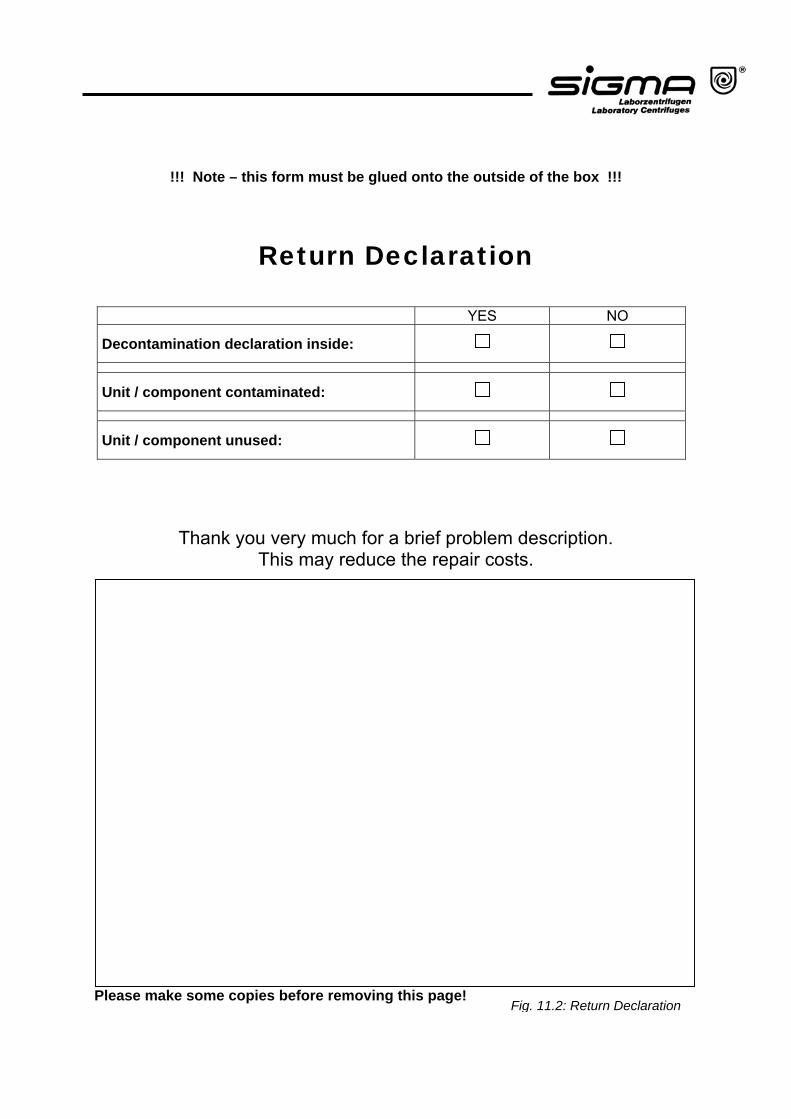
!!! Note – this form must be glued onto the outside of the box !!!
Return Declaration
YES NO
Decontamination declaration inside:
Unit / component contaminated:
Unit / component unused:
Thank you very much for a brief problem description. This may reduce the repair costs.
Please make some copies before removing this page!
Fig. 11.2: Return Declaration

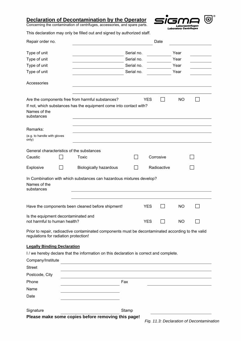
Declaration of Decontamination by the Operator Concerning the contamination of centrifuges, accessories, and spare parts. This declaration may only be filled out and signed by authorized staff.
Repair order no. Date Type of unit Serial no. Year Type of unit Serial no. Year Type of unit Serial no. Year Type of unit Serial no. Year Accessories
Are the components free from harmful substances? YES NO If not, which substances has the equipment come into contact with? Names of the substances
Remarks: (e.g. to handle with gloves only) General characteristics of the substances Caustic Toxic Corrosive Explosive Biologically hazardous Radioactive In Combination with which substances can hazardous mixtures develop? Names of the substances
Have the components been cleaned before shipment! YES NO Is the equipment decontaminated and not harmful to human health? YES NO Prior to repair, radioactive contaminated components must be decontaminated according to the valid regulations for radiation protection! Legally Binding DeclarationI / we hereby declare that the information on this declaration is correct and complete.
Company/Institute
Street
Postcode, City
Phone Fax
Name
Date
Signature Stamp Please make some copies before removing this page!
Fig. 11.3: Declaration of Decontamination

Operating Manual SIGMA 2-6E page 65 of 71 Version 04/2008
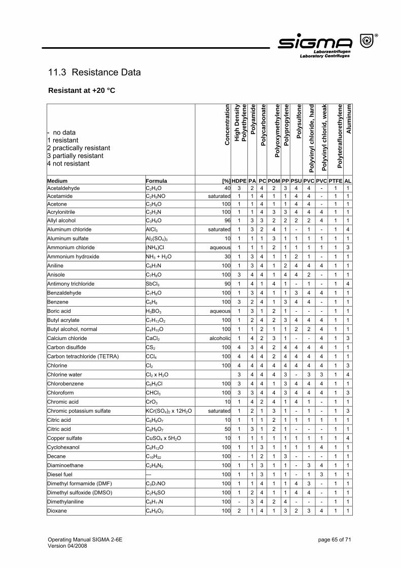
11.3 Resistance Data Resistant at +20 °C
- no data 1 resistant 2 practically resistant 3 partially resistant 4 not resistant
Con
cent
ratio
n H
igh
Den
sity
Po
lyet
hyle
ne
Poly
amid
e Po
lyca
rbon
ate
Poly
oxym
ethy
lene
Po
lypr
opyl
ene
Poly
sulfo
ne
Poly
viny
l chl
orid
e, h
ard
Poly
viny
l chl
orid
, wea
k
Poly
tetr
aflu
oret
hyle
ne
Alu
min
um
Medium Formula [%] HDPE PA PC POM PP PSU PVC PVC PTFE ALAcetaldehyde C2H4O 40 3 2 4 2 3 4 4 - 1 1Acetamide C2H5NO saturated 1 1 4 1 1 4 4 - 1 1Acetone C3H6O 100 1 1 4 1 1 4 4 - 1 1Acrylonitrile C3H3N 100 1 1 4 3 3 4 4 4 1 1Allyl alcohol C3H6O 96 1 3 3 2 2 2 2 4 1 1Aluminum chloride AlCl3 saturated 1 3 2 4 1 - 1 - 1 4
Aluminum sulfate Al2(SO4)3 10 1 1 1 3 1 1 1 1 1 1Ammonium chloride (NH4)Cl aqueous 1 1 1 2 1 1 1 1 1 3
Ammonium hydroxide NH3 + H2O 30 1 3 4 1 1 2 1 - 1 1
Aniline C6H7N 100 1 3 4 1 2 4 4 4 1 1
Anisole C7H8O 100 3 4 4 1 4 4 2 - 1 1
Antimony trichloride SbCl3 90 1 4 1 4 1 - 1 - 1 4
Benzaldehyde C7H6O 100 1 3 4 1 1 3 4 4 1 1
Benzene C6H6 100 3 2 4 1 3 4 4 - 1 1
Boric acid H3BO3 aqueous 1 3 1 2 1 - - - 1 1
Butyl acrylate C7H12O2 100 1 2 4 2 3 4 4 4 1 1
Butyl alcohol, normal C4H10O 100 1 1 2 1 1 2 2 4 1 1
Calcium chloride CaCl2 alcoholic 1 4 2 3 1 - - 4 1 3
Carbon disulfide CS2 100 4 3 4 2 4 4 4 4 1 1
Carbon tetrachloride (TETRA) CCl4 100 4 4 4 2 4 4 4 4 1 1
Chlorine Cl2 100 4 4 4 4 4 4 4 4 1 3
Chlorine water Cl2 x H2O 3 4 4 4 3 - 3 3 1 4
Chlorobenzene C6H5Cl 100 3 4 4 1 3 4 4 4 1 1
Chloroform CHCl3 100 3 3 4 4 3 4 4 4 1 3
Chromic acid CrO3 10 1 4 2 4 1 4 1 - 1 1
Chromic potassium sulfate KCr(SO4)2 x 12H2O saturated 1 2 1 3 1 - 1 - 1 3
Citric acid C6H8O7 10 1 1 1 2 1 1 1 1 1 1
Citric acid C6H8O7 50 1 3 1 2 1 - - - 1 1
Copper sulfate CuSO4 x 5H2O 10 1 1 1 1 1 1 1 1 1 4
Cyclohexanol C6H12O 100 1 1 3 1 1 1 1 4 1 1
Decane C10H22 100 - 1 2 1 3 - - - 1 1
Diaminoethane C2H8N2 100 1 1 3 1 1 - 3 4 1 1
Diesel fuel — 100 1 1 3 1 1 - 1 3 1 1
Dimethyl formamide (DMF) C3D7NO 100 1 1 4 1 1 4 3 - 1 1
Dimethyl sulfoxide (DMSO) C2H6SO 100 1 2 4 1 1 4 4 - 1 1
Dimethylaniline C8H11N 100 - 3 4 2 4 - - - 1 1
Dioxane C4H8O2 100 2 1 4 1 3 2 3 4 1 1
Operating Manual SIGMA 2-6E page 66 of 71 Version 04/2008
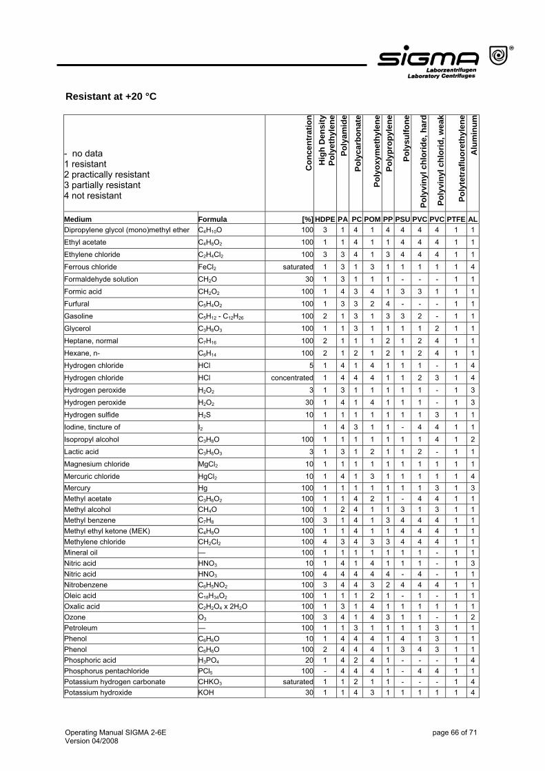
Resistant at +20 °C
- no data 1 resistant 2 practically resistant 3 partially resistant 4 not resistant
Con
cent
ratio
n H
igh
Den
sity
Po
lyet
hyle
ne
Poly
amid
e Po
lyca
rbon
ate
Poly
oxym
ethy
lene
Po
lypr
opyl
ene
Poly
sulfo
ne
Poly
viny
l chl
orid
e, h
ard
Poly
viny
l chl
orid
, wea
k
Poly
tetr
aflu
oret
hyle
ne
Alu
min
um
Medium Formula [%] HDPE PA PC POM PP PSU PVC PVC PTFE ALDipropylene glycol (mono)methyl ether C4H10O 100 3 1 4 1 4 4 4 4 1 1
Ethyl acetate C4H8O2 100 1 1 4 1 1 4 4 4 1 1
Ethylene chloride C2H4Cl2 100 3 3 4 1 3 4 4 4 1 1
Ferrous chloride FeCl2 saturated 1 3 1 3 1 1 1 1 1 4
Formaldehyde solution CH2O 30 1 3 1 1 1 - - - 1 1
Formic acid CH2O2 100 1 4 3 4 1 3 3 1 1 1
Furfural C5H4O2 100 1 3 3 2 4 - - - 1 1
Gasoline C5H12 - C12H26 100 2 1 3 1 3 3 2 - 1 1
Glycerol C3H8O3 100 1 1 3 1 1 1 1 2 1 1
Heptane, normal C7H16 100 2 1 1 1 2 1 2 4 1 1
Hexane, n- C6H14 100 2 1 2 1 2 1 2 4 1 1
Hydrogen chloride HCl 5 1 4 1 4 1 1 1 - 1 4
Hydrogen chloride HCl concentrated 1 4 4 4 1 1 2 3 1 4
Hydrogen peroxide H2O2 3 1 3 1 1 1 1 1 - 1 3
Hydrogen peroxide H2O2 30 1 4 1 4 1 1 1 - 1 3
Hydrogen sulfide H2S 10 1 1 1 1 1 1 1 3 1 1
Iodine, tincture of I2 1 4 3 1 1 - 4 4 1 1
Isopropyl alcohol C3H8O 100 1 1 1 1 1 1 1 4 1 2
Lactic acid C3H6O3 3 1 3 1 2 1 1 2 - 1 1
Magnesium chloride MgCl2 10 1 1 1 1 1 1 1 1 1 1
Mercuric chloride HgCl2 10 1 4 1 3 1 1 1 1 1 4Mercury Hg 100 1 1 1 1 1 1 1 3 1 3Methyl acetate C3H6O2 100 1 1 4 2 1 - 4 4 1 1Methyl alcohol CH4O 100 1 2 4 1 1 3 1 3 1 1Methyl benzene C7H8 100 3 1 4 1 3 4 4 4 1 1Methyl ethyl ketone (MEK) C4H8O 100 1 1 4 1 1 4 4 4 1 1Methylene chloride CH2Cl2 100 4 3 4 3 3 4 4 4 1 1Mineral oil — 100 1 1 1 1 1 1 1 - 1 1Nitric acid HNO3 10 1 4 1 4 1 1 1 - 1 3Nitric acid HNO3 100 4 4 4 4 4 - 4 - 1 1Nitrobenzene C6H5NO2 100 3 4 4 3 2 4 4 4 1 1Oleic acid C18H34O2 100 1 1 1 2 1 - 1 - 1 1Oxalic acid C2H2O4 x 2H2O 100 1 3 1 4 1 1 1 1 1 1Ozone O3 100 3 4 1 4 3 1 1 - 1 2Petroleum — 100 1 1 3 1 1 1 1 3 1 1Phenol C6H6O 10 1 4 4 4 1 4 1 3 1 1Phenol C6H6O 100 2 4 4 4 1 3 4 3 1 1Phosphoric acid H3PO4 20 1 4 2 4 1 - - - 1 4Phosphorus pentachloride PCl5 100 - 4 4 4 1 - 4 4 1 1Potassium hydrogen carbonate CHKO3 saturated 1 1 2 1 1 - - - 1 4Potassium hydroxide KOH 30 1 1 4 3 1 1 1 1 1 4
Operating Manual SIGMA 2-6E page 67 of 71 Version 04/2008
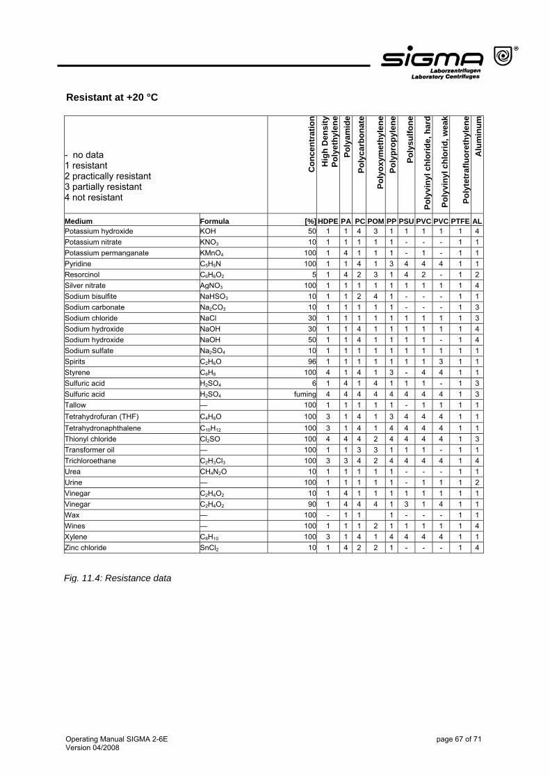
Resistant at +20 °C
- no data 1 resistant 2 practically resistant 3 partially resistant 4 not resistant
Con
cent
ratio
n H
igh
Den
sity
Po
lyet
hyle
ne
Poly
amid
e Po
lyca
rbon
ate
Poly
oxym
ethy
lene
Po
lypr
opyl
ene
Poly
sulfo
ne
Poly
viny
l chl
orid
e, h
ard
Poly
viny
l chl
orid
, wea
k
Poly
tetr
aflu
oret
hyle
ne
Alu
min
um
Medium Formula [%] HDPE PA PC POM PP PSU PVC PVC PTFE ALPotassium hydroxide KOH 50 1 1 4 3 1 1 1 1 1 4Potassium nitrate KNO3 10 1 1 1 1 1 - - - 1 1Potassium permanganate KMnO4 100 1 4 1 1 1 - 1 - 1 1Pyridine C5H5N 100 1 1 4 1 3 4 4 4 1 1Resorcinol C6H6O2 5 1 4 2 3 1 4 2 - 1 2Silver nitrate AgNO3 100 1 1 1 1 1 1 1 1 1 4Sodium bisulfite NaHSO3 10 1 1 2 4 1 - - - 1 1Sodium carbonate Na2CO3 10 1 1 1 1 1 - - - 1 3Sodium chloride NaCl 30 1 1 1 1 1 1 1 1 1 3Sodium hydroxide NaOH 30 1 1 4 1 1 1 1 1 1 4Sodium hydroxide NaOH 50 1 1 4 1 1 1 1 - 1 4Sodium sulfate Na2SO4 10 1 1 1 1 1 1 1 1 1 1Spirits C2H6O 96 1 1 1 1 1 1 1 3 1 1Styrene C8H8 100 4 1 4 1 3 - 4 4 1 1Sulfuric acid H2SO4 6 1 4 1 4 1 1 1 - 1 3Sulfuric acid H2SO4 fuming 4 4 4 4 4 4 4 4 1 3Tallow — 100 1 1 1 1 1 - 1 1 1 1Tetrahydrofuran (THF) C4H8O 100 3 1 4 1 3 4 4 4 1 1Tetrahydronaphthalene C10H12 100 3 1 4 1 4 4 4 4 1 1Thionyl chloride Cl2SO 100 4 4 4 2 4 4 4 4 1 3Transformer oil — 100 1 1 3 3 1 1 1 - 1 1Trichloroethane C2H3Cl3 100 3 3 4 2 4 4 4 4 1 4Urea CH4N2O 10 1 1 1 1 1 - - - 1 1Urine — 100 1 1 1 1 1 - 1 1 1 2Vinegar C2H4O2 10 1 4 1 1 1 1 1 1 1 1Vinegar C2H4O2 90 1 4 4 4 1 3 1 4 1 1Wax — 100 - 1 1 1 - - - 1 1Wines — 100 1 1 1 2 1 1 1 1 1 4Xylene C8H10 100 3 1 4 1 4 4 4 4 1 1Zinc chloride SnCl2 10 1 4 2 2 1 - - - 1 4
Fig. 11.4: Resistance data

12 Index Acceleration curves
- see also the softstart and softstop function ..........................................................................27 Acceleration time
- see also the softstart and softstop function ..........................................................................33 Acid ................................................................................................................................65, 66, 67 Adapter................................................................................................................48, 50, 51, 53, 55 Alkaline solutions ...........................................................................................................19, 44, 45 Ambient temperature..................................................................................................................13 Angle rotor..........................................................................................................31, 32, 48, 52, 53 Auto-Lid-Open function ..............................................................................................................40 Bucket ............................................................................18, 19, 31, 45, 46, 47, 48, 50, 51, 52, 55 Carrier ....................................................................................................31, 32, 46, 47, 48, 50, 51 Centrifugation with low Capacity ................................................................................................31 Centrifuges
- definition ...............................................................................................................................11 Chemical reactions.....................................................................................................................46 Cleaning agents ...................................................................................................................44, 45 Condensation .............................................................................................................................24 Connected load ..........................................................................................................................13 Connecting cable .......................................................................................................................15 Contamination
- contamination with harmful substances ...................................................................20, 44, 45 Continuous heat resistance........................................................................................................47 Continuous run.....................................................................................................................27, 35 Corrosion
- chemical changes of the material surface ..................................18, 20, 21, 32, 44, 45, 46, 47 Cracks ............................................................................................................................21, 32, 46 Current consumption..................................................................................................................13 Damage of the surface...............................................................................................................46 Dangerous goods.......................................................................................................................19 Deceleration curves
- see also the softstart and softstop function ..........................................................................27 Deceleration time
- see also the softstart and softstop function ..........................................................................33 Density ...........................................................................................................................18, 57, 65 Disinfectants...............................................................................................................................47 Electrical connection ..................................................................................................................13 EMC as per EN 61326 ...............................................................................................................13 Emergency circuit breaker .........................................................................................................24 Equipotential bonding screw ......................................................................................................28 Error messages....................................................................................................................28, 41 Errors ...................................................................................................................................28, 43 Fire-fighting measures ...............................................................................................................21 Fuse ...............................................................................................................................15, 24, 41 General Conditions ....................................................................................................................49 Glass particles............................................................................................................................47 Gravitational field ...........................................................................................................13, 50, 57 Grease for load-bearing bolts.........................................................................................15, 44, 46 Ground wire check .....................................................................................................................28 Ground wire connector...............................................................................................................24
Operating Manual SIGMA 2-6E page 69 of 71 Version 04/2008
Hazard warnings ............................................................................................................16, 19, 49 Hazards..........................................................................................................................11, 20, 21 Humidity .....................................................................................................................................13 Imbalance.....................................................................................................19, 31, 32, 43, 46, 47 Increment
- amount by which a quantity is increased........................................................................35, 36 Infectious substances
- material including infectious pathogenes .................................................................18, 20, 47 Inflammable substances ............................................................................................................20 IP code .......................................................................................................................................13 Load-bearing bolts .....................................................................................................................46 Mains power switch..................................................................................................29, 39, 41, 42 Malfunction...............................................................................................................18, 24, 41, 43 Maximum speed for tubes..........................................................................................................55 Measures for the containment of harmful emissions..................................................................21 Motor shaft ...............................................................................................................21, 23, 30, 44 Multiple carrier..........................................................................................................32, 46, 50, 51 Noise level..................................................................................................................................13 Nominal voltage .........................................................................................................................13 Operating voltage.......................................................................................................................24 Operational safety ................................................................................................................20, 45 Overseas shipping .....................................................................................................................22 Padlock symbol ..........................................................................................................................39 Parameter
- value characterizing the performance ..............................................13, 27, 36, 37, 39, 43, 57 Pathogenic substances
- material including pathogenes............................................................................20, 44, 45, 47 Performance data.......................................................................................................................13 Pivot bearing ..............................................................................................................................47 Power consumption....................................................................................................................13 Power cord ...............................................................................................................24, 41, 42, 44 Pressure marks ..........................................................................................................................46 Prevention of accidents........................................................................................................11, 17 Program ...............................................................................................................................27, 38 Program number ........................................................................................................................38 Protection class..........................................................................................................................13 Protective earth ..........................................................................................................................16 Radioactive substances
- material emitting harmful radiation .....................................................................18, 20, 44, 45 Radius ..................................................................................................................................56, 57 Relative centrifugal force................................................................................................27, 37, 57 Rotor geometry ..........................................................................................................................37 Rotor number .............................................................................................................................37 Rotor tie-down screw ...........................................................................................................30, 46 Rotor wrench........................................................................................................................15, 30 Rubber cushions ......................................................................................................45, 46, 47, 48 Safety class................................................................................................................................24 Safety distance.....................................................................................................................19, 24 Safety instructions..........................................................................................................11, 16, 18 Serial number.............................................................................................................................13 Short run ..............................................................................................................................27, 35 Slushing oil.....................................................................................................................15, 45, 46 Solvents .........................................................................................................................19, 44, 45
Operating Manual SIGMA 2-6E page 70 of 71 Version 04/2008
Sound signal ........................................................................................................................40, 41 Spare fuse..................................................................................................................................15 Spare parts.....................................................................................................................43, 55, 59 Storage temperature ............................................................................................................13, 22 Stress-corrosion .........................................................................................................................46 Supply voltage............................................................................................................................24 Swing-out rotor.....................................................................................................................31, 50 Toxic substances .....................................................................................................18, 20, 44, 45 Transport safety device........................................................................................................22, 23 Trunnion pins .............................................................................................................................21 UV radiation .........................................................................................................................24, 44 Ventilation ............................................................................................................................24, 43
Operating Manual SIGMA 2-6E page 71 of 71 Version 04/2008