label switched path (lsp) ping/trace over mpls network … filethe multiprotocol label switching...
TRANSCRIPT

Internet Engineering Task Force N. AkiyaInternet-Draft G. SwallowUpdates: 4379,6790 (if approved) C. PignataroIntended status: Standards Track Cisco SystemsExpires: April 24, 2014 October 21, 2013
Label Switched Path (LSP) Ping/Trace over MPLS Network using Entropy Labels (EL) draft-akiya-mpls-entropy-lsp-ping-00
Abstract
The Multiprotocol Label Switching (MPLS) Label Switched Path (LSP) Ping and Traceroute are used to exercise specific paths of Equal Cost Multipath (ECMP). This ability has been lost on some scenarios which makes use of [RFC6790]: Entropy Labels (EL).
This document extends the MPLS LSP Ping and Traceroute mechanisms to restore the ability of exercising specific paths of ECMP over LSP which make use of Entropy Label. This document updates [RFC4379] and [RFC6790].
Requirements Language
The key words "MUST", "MUST NOT", "REQUIRED", "SHALL", "SHALL NOT", "SHOULD", "SHOULD NOT", "RECOMMENDED", "MAY", and "OPTIONAL" in this document are to be interpreted as described in RFC 2119 [RFC2119].
Status of This Memo
This Internet-Draft is submitted in full conformance with the provisions of BCP 78 and BCP 79.
Internet-Drafts are working documents of the Internet Engineering Task Force (IETF). Note that other groups may also distribute working documents as Internet-Drafts. The list of current Internet- Drafts is at http://datatracker.ietf.org/drafts/current/.
Internet-Drafts are draft documents valid for a maximum of six months and may be updated, replaced, or obsoleted by other documents at any time. It is inappropriate to use Internet-Drafts as reference material or to cite them other than as "work in progress."
This Internet-Draft will expire on April 24, 2014.
Copyright Notice
Akiya, et al. Expires April 24, 2014 [Page 1]

Internet-Draft LSP Ping over Entropy October 2013
Copyright (c) 2013 IETF Trust and the persons identified as the document authors. All rights reserved.
This document is subject to BCP 78 and the IETF Trust’s Legal Provisions Relating to IETF Documents (http://trustee.ietf.org/license-info) in effect on the date of publication of this document. Please review these documents carefully, as they describe your rights and restrictions with respect to this document. Code Components extracted from this document must include Simplified BSD License text as described in Section 4.e of the Trust Legal Provisions and are provided without warranty as described in the Simplified BSD License.
Table of Contents
1. Introduction . . . . . . . . . . . . . . . . . . . . . . . . 2 2. Overview . . . . . . . . . . . . . . . . . . . . . . . . . . 3 3. Multipath Type 9 . . . . . . . . . . . . . . . . . . . . . . 5 4. Initiating LSR Procedures . . . . . . . . . . . . . . . . . . 6 5. Responder LSR Procedures . . . . . . . . . . . . . . . . . . 7 5.1. IP Based Load Balancer & Not Imposing ELI/EL . . . . . . 7 5.2. IP Based Load Balancer & Imposing ELI/EL . . . . . . . . 8 5.3. Label Based Load Balancer & Not Imposing ELI/EL . . . . . 8 5.4. Label Based Load Balancer & Imposing ELI/EL . . . . . . . 9 5.5. FAT MS-PW Stitching LSR . . . . . . . . . . . . . . . . . 9 6. Entropy Label FEC . . . . . . . . . . . . . . . . . . . . . . 10 7. DS Flags: L and E . . . . . . . . . . . . . . . . . . . . . . 10 8. New Multipath Information Type: 10 . . . . . . . . . . . . . 11 9. Unsupported Cases . . . . . . . . . . . . . . . . . . . . . . 13 10. Security Considerations . . . . . . . . . . . . . . . . . . . 13 11. IANA Considerations . . . . . . . . . . . . . . . . . . . . . 13 11.1. DS Flags . . . . . . . . . . . . . . . . . . . . . . . . 13 11.2. Multipath Information Types . . . . . . . . . . . . . . 13 11.3. Entropy Label FEC . . . . . . . . . . . . . . . . . . . 13 12. Acknowledgements . . . . . . . . . . . . . . . . . . . . . . 14 13. Contributing Authors . . . . . . . . . . . . . . . . . . . . 14 14. References . . . . . . . . . . . . . . . . . . . . . . . . . 14 14.1. Normative References . . . . . . . . . . . . . . . . . . 14 14.2. Informative References . . . . . . . . . . . . . . . . . 14 Authors’ Addresses . . . . . . . . . . . . . . . . . . . . . . . 14
1. Introduction
Akiya, et al. Expires April 24, 2014 [Page 2]

Internet-Draft LSP Ping over Entropy October 2013
Section 3.3.1 of [RFC4379] specifies multipath information encoding which can be used by LSP Ping initiator to trace and validate all ECMP paths between ingress and egress. These encodings are sufficient when all the LSRs along the path(s), between ingress and egress, consider same set of "keys" as input for load balancing algorithm: all IP based or all label based.
With introduction of [RFC6790], it is quite normal to see set of LSRs performing load balancing based on EL/ELI while others still follow the traditional way (IP based). This results in LSP Ping initiator not be able to trace and validate all ECMP paths in following scenarios:
o One or more transit LSRs along ELI/EL imposed LSP do not perform ECMP load balancing based on EL (hashes based on "keys" including IP destination address). This scenario is not only possible but quite common due transit LSRs not implementing [RFC6790] or transit LSRs implementing [RFC6790] but not implementing suggested transit LSR behavior in Section 4.3 of [RFC6790].
o Two or more LSPs stitched together with at least one LSP being ELI /EL imposing LSP. Such scenarios are described in [I-D.ravisingh-mpls-el-for-seamless-mpls].
These scenarios will be quite common because every deployment of [RFC6790] will invariably end up with nodes that support ELI/EL and nodes that do not. There will typically be areas that support ELI/EL and areas that do not.
As pointed out in [RFC6790] the procedures of [RFC4379] with respect to multipath information type {9} are incomplete. However [RFC6790] does not actually update [RFC4379]. Further the specific EL location is not clearly defined, particularly in the case of FAT Pseudowires [RFC6391]. Herein is defined a new FEC Stack sub-TLV for the Entropy Label. Section 3 of this document updates the procedures for multipath information type {9}.
2. Overview
[RFC4379] describes LSP traceroute as an operation performed through initiating LSR sending LSP Ping packet (LSP echo request) with incrementing TTL, starting with TTL of one. Initiating LSR discovers and exercises ECMP by obtaining multipath information from each transit LSR and using specific destination IP address or specific entropy label.
LSP Ping initiating LSR sends LSP echo request with multipath information. This multipath information is described in DSMAP/DDMAP
Akiya, et al. Expires April 24, 2014 [Page 3]

Internet-Draft LSP Ping over Entropy October 2013
TLV of echo request, and can contain set of IP addresses or set of labels today. Multipath information types {2, 4, 8} carry set of IP addresses and multipath information type {9} carries set of labels. Responder LSR (receiver of LSP echo request) is to determine subset of initiator specified multipath information which load balances to each downstream (outgoing interface). Responder LSR sends LSP echo reply with resulting multipath information per downstream (outgoing interface) back to the initiating LSR. Initiating LSR is then able to use specific IP destination address or specific label to exercise specific ECMP path on the responder LSR.
Current behavior is problematic in following scenarios:
o Initiating LSR sends IP multipath information, but responder LSR load balances on labels.
o Initiating LSR sends label multipath information, but responder LSR load balances on IP addresses.
o Initiating LSR sends any of existing multipath information to ELI/ EL imposing LSR, but initiating LSR can only continue to discover and exercise specific path of ECMP if ELI/EL imposing LSR responds with both IP addresses and associated EL corresponding to each IP address. This is because:
* ELI/EL imposing LSR that is a stitching point will load balance based on IP address.
* Downstream LSR(s) of ELI/EL imposing LSR may load balance based on ELs.
o Initiating LSR sends any of existing multipath information to ELI/ EL imposing LSR, but initiating LSR can only continue to discover and exercise specific path of ECMP if ELI/EL imposing LSR responds with both labels and associated EL corresponding to label. This is because:
* ELI/EL imposing LSR that is a stitching point will load balance based on EL from previous LSP and imposes new EL.
* Downstream LSR(s) of ELI/EL imposing LSR may load balance based on new ELs.
The above scenarios point to how the existing multipath information is insufficient when LSP traceroute is operated on an LSP with Entropy Labels described by [RFC6790]. Therefore, this document defines a multipath information type to be used in the DSMAP/DDMAP of LSP echo request/reply packets in Section 8.
Akiya, et al. Expires April 24, 2014 [Page 4]

Internet-Draft LSP Ping over Entropy October 2013
In addition, responder LSR can reply with empty multipath information if no IP address set or label set from received multipath information matched load balancing to a downstream. Empty return is also possible if initiating LSR sends multipath information of one type, IP address or label, but responder LSR load balances on the other type. To disambiguate between the two results, this document introduces new flags in the DSMAP/DDMAP TLV to allow responder LSR to describe the load balance technique being used.
It is required that all LSRs along the LSP understand new flags as well as new multipath information type. It is also required that initiating LSR can select both IP destination address and label to use on transmitting LSP echo request packets. Two additional DS Flags are defined for the DSMAP and DDMAP TLVs in Section 7.
3. Multipath Type 9
[RFC4379] defined multipath type {9} for tracing of LSPs where label based load-balancing is used. However, as pointed out in [RFC6790], the procedures for using this type are incomplete. First, the specific location of the label was not defined. What was assumed, but not spelled out, was that the presence of multipath type {9} meant the responder should act as if the payload of the received packet were non-IP and that the bottom-of-stack label should be replaced by the values indicated by multipath type {9} to determine their respective out-going interfaces.
Further, with the introduction of [RFC6790], entropy labels may now appear anywhere in a label stack.
This section defines to which labels multipath type {9} can apply. Additionally it defines procedures for tracing pseudowires and flow- aware pseudowires. These procedures pertain to the use of multipath information type {9} as well as type {10}.
Section 6 defines a new FEC-Stack sub-TLV to indicate and entropy label. Multipath type {9} applies exclusively to this sub-TLV. Any LSP Ping message containing a DD-MAP or DS-MAP with multipath type {9} MUST include an EL_FEC at the bottom of the FEC-Stack.
When an MPLS echo request message is received containing a FEC-Stack with an EL-FEC at the bottom of the FEC stack and is not preceded by an entropy label, the responder must behave (for load balancing purposes) as if the first word of the message were a Pseudowire Control Word.
In order to trace a non-FAT pseudowire, instead of including the appropriate PW-FEC in the FEC-Stack, an EL-FEC is included. Tracing
Akiya, et al. Expires April 24, 2014 [Page 5]

Internet-Draft LSP Ping over Entropy October 2013
in this way will cause compliant routers to return the proper outgoing interface. Note that this procedure only traces to the end of the MPLS transport LSP (e.g. LDP and/or RSVP). To actually verify the PW-FEC or in the case of a MS-PW, to determine the next pseudowire label value, the initiator MUST repeat that step of the trace, (i.e., repeating the TTL value used) but with the FEC-Stack modified to contain the appropriate PW-FEC.
In order to trace a FAT pseudowire, the initiator includes an EL-FEC at the bottom of the FEC-Stack and pushes the appropriate PW-FEC onto the FEC-Stack.
4. Initiating LSR Procedures
In order to facilitate the flow of the following text we speak in terms of a boolean called EL_LSP maintained by the initiating LSR. This value controls the multipath information type to be used in transmitted echo request packets. When the initiating LSR is transmitting an echo request packet with DSMAP/DDMAP with a non-zero multipath information type, then EL_LSP boolean MUST be consulted to determine the multipath information type to use.
In addition to procedures described in [RFC4379] as updated by Section 3 and [RFC6424], initiating LSR MUST operate with following procedures.
o When initiating LSR is IP based load balancer (not imposing ELI/ EL), initialize EL_LSP=False.
o When initiating LSR imposes ELI/EL, initialize EL_LSP=True.
o When initiating LSR is transmitting non-zero multipath information type:
If (EL_LSP) initiating LSR MUST use multipath information type {10}.
Else initiating LSR MUST use multipath information type {2, 4, 8, 9}.
o When initiating LSR is transmitting multipath information type {10}, both "IP Multipath Information" and "Label Multipath Information" MUST be included, and "IP Associated Label Multipath Information" MUST be omitted (NULL).
o When initiating LSR receives echo reply with {L=0, E=1} in DS flags with valid contents, set EL_LSP=True.
Akiya, et al. Expires April 24, 2014 [Page 6]

Internet-Draft LSP Ping over Entropy October 2013
In following conditions, initiating LSR may have lost the ability to exercise specific ECMP paths. Initiating LSR MAY continue with "best effort".
o Received echo reply contains empty multipath information.
o Received echo reply contains {L=0, E=<any>} DS flags, but does not contain IP multipath information.
o Received echo reply contains {L=1, E=<any>} DS flags, but does not contain label multipath information.
o Received echo reply contains {L=<any>, E=1} DS flags, but does not contain associated label multipath information.
o IP multipath information types {2, 4, 8} sent, and received echo reply with {L=1, E=0} in DS flags.
o Multipath information type {10} sent, and received echo reply with multipath information type other than {10}.
5. Responder LSR Procedures
Common Procedures: Responder LSR receiving LSP echo request packet with multipath information type {10} MUST validate following contents. Any deviation MUST result in responder LSR to consider the packet as malformed and return code 1 (Malformed echo request received) in LSP echo reply packet.
o IP multipath information MUST be included.
o Label multipath information MUST be included.
o IP associated label multipath information MUST be omitted (NULL).
Following subsections describe expected responder LSR procedures when echo reply is to include DSMAP/DDMAP TLVs, based on local load balance technique being employed. In case responder LSR performs deviating load balance techniques per downstream basis, appropriate procedures matching to each downstream load balance technique MUST be operated.
5.1. IP Based Load Balancer & Not Imposing ELI/EL
o Responder MUST set {L=0, E=0} in DS flags.
o If multipath information type {2, 4, 8} is received, responder MUST comply with [RFC4379]/[RFC6424].
Akiya, et al. Expires April 24, 2014 [Page 7]

Internet-Draft LSP Ping over Entropy October 2013
o If multipath information type {9} is received, responder MUST reply with multipath type {0}.
o If multipath information type {10} is received, responder MUST reply with multipath information type {10}. "Label Multipath Information" and "Associated Label Multipath Information" sections MUST be omitted (NULL). If no matching IP address is found, then "IPMultipathType" field MUST be set to multipath information type {0} and "IP Multipath Information" section MUST also be omitted (NULL). If at least one matching IP address is found, then "IPMultipathType" field MUST be set to appropriate multipath information type {2, 4, 8} and "IP Multipath Information" section MUST be included.
5.2. IP Based Load Balancer & Imposing ELI/EL
o Responder MUST set {L=0, E=1} in DS flags.
o If multipath information type {9} is received, responder MUST reply with multipath type {0}.
o If multipath type {2, 4, 8, 10} is received, responder MUST respond with multipath type {10}. "Label Multipath Information" section MUST be omitted (NULL). IP address set specified in received IP multipath information MUST be used to determine the returning IP/Label pairs. If received multipath information type was {10}, received "Label Multipath Information" sections MUST NOT be used to determine the associated label portion of returning IP/ Label pairs. If no matching IP address is found, then "IPMultipathType" field MUST be set to multipath information type {0} and "IP Multipath Information" section MUST be omitted (NULL). In addition, "Assoc Label Multipath Length" MUST be set to 0, and "Associated Label Multipath Information" section MUST also be omitted (NULL). If at least one matching IP address is found, then "IPMultipathType" field MUST be set to appropriate multipath information type {2, 4, 8} and "IP Multipath Information" section MUST be included. In addition, "Associated Label Multipath Information" section MUST be populated with list of labels corresponding to each IP address specified in "IP Multipath Information" section. "Assoc Label Multipath Length" MUST be set to appropriate value.
5.3. Label Based Load Balancer & Not Imposing ELI/EL
o Responder MUST set {L=1, E=0} in DS flags.
o If multipath information type {2, 4, 8} is received, responder MUST reply with multipath type {0}.
Akiya, et al. Expires April 24, 2014 [Page 8]

Internet-Draft LSP Ping over Entropy October 2013
o If multipath information type {9} is received, responder MUST comply with [RFC4379] /[RFC6424] as updated by Section 3.
o If multipath information type {10} is received, responder MUST reply with multipath information type {10}. "IP Multipath Information" and "Associated Label Multipath Information" sections MUST be omitted (NULL). If no matching label is found, then "LbMultipathType" field MUST be set to multipath information type {0} and "Label Multipath Information" section MUST also be omitted (NULL). If at least one matching label is found, then "LbMultipathType" field MUST be set to appropriate multipath information type {9} and "Label Multipath Information" section MUST be included.
5.4. Label Based Load Balancer & Imposing ELI/EL
o Responder MUST set {L=1, E=1} in DS flags.
o If multipath information type {2, 4, 8} is received, responder MUST reply with multipath type {0}.
o If multipath type {9, 10} is received, responder MUST respond with multipath type {10}. "IP Multipath Information" section MUST be omitted (NULL). Label set specified in received label multipath information MUST be used to determine the returning Label/Label pairs. If received multipath information type was {10}, received "Label Multipath Information" sections MUST NOT be used to determine the associated label portion of returning Label/Label pairs. If no matching label is found, then "LbMultipathType" field MUST be set to multipath information type {0} and "Label Multipath Information" section MUST be omitted (NULL). In addition, "Assoc Label Multipath Length" MUST be set to 0, and "Associated Label Multipath Information" section MUST also be omitted (NULL). If at least one matching label is found, then "LbMultipathType" field MUST be set to appropriate multipath information type {9} and "Label Multipath Information" section MUST be included. In addition, "Associated Label Multipath Information" section MUST be populated with list of labels corresponding to each label specified in "Label Multipath Information" section. "Assoc Label Multipath Length" MUST be set to appropriate value.
5.5. FAT MS-PW Stitching LSR
MS-PW stitching LSR that xconnects flow-aware pseudowires behaves in one of two ways:
Akiya, et al. Expires April 24, 2014 [Page 9]

Internet-Draft LSP Ping over Entropy October 2013
o Load balances on previous flow label, and carries over same flow label. For this case, stitching LSR is to behave as procedures described in Section 5.3.
o Load balances on previous flow label, and replaces flow label with newly computed. For this case, stitching LSR is to behave as procedures described in Section 5.4.
6. Entropy Label FEC
Entropy Label Indicator (ELI) is a reserved label that has no explicit FEC associated, and has label value 7 assigned from the reserved range. Use Nil FEC as Target FEC Stack sub-TLV to account for ELI in a Target FEC Stack TLV.
Entropy Label (EL) is a special purpose label with label value being discretionary (i.e. label value may not be from the reserved range). For LSP verification mechanics to perform its purpose, it is necessary for a Target FEC Stack sub-TLV to clearly describe EL, particularly in the scenario where label stack does not carry ELI (ex: FAT-PW [RFC6391]). Therefore, this document defines a EL FEC to allow a Target FEC Stack sub-TLV to be added to the Target FEC Stack to account for EL.
The Length is 4. Labels are 20-bit values treated as numbers.
0 1 2 3 0 1 2 3 4 5 6 7 8 9 0 1 2 3 4 5 6 7 8 9 0 1 2 3 4 5 6 7 8 9 0 1 +-+-+-+-+-+-+-+-+-+-+-+-+-+-+-+-+-+-+-+-+-+-+-+-+-+-+-+-+-+-+-+-+ | Label | MBZ | +-+-+-+-+-+-+-+-+-+-+-+-+-+-+-+-+-+-+-+-+-+-+-+-+-+-+-+-+-+-+-+-+
Label is the actual label value inserted in the label stack; the MBZ fields MUST be zero when sent and ignored on receipt.
7. DS Flags: L and E
Two flags, L and E, are added in DS Flags field of the DSMAP/DDMAP TLVs. Both flags MUST NOT be set in echo request packets when sending, and ignored when received. Zero, one or both new flags MUST be set in echo reply packets.
DS Flags --------
0 1 2 3 4 5 6 7 +-+-+-+-+-+-+-+-+
Akiya, et al. Expires April 24, 2014 [Page 10]

Internet-Draft LSP Ping over Entropy October 2013
| MBZ |L|E|I|N| +-+-+-+-+-+-+-+-+
Flag Name and Meaning ---- ---------------- L Label based load balance indicator This flag MUST be set to zero in the echo request. LSR which performs load balancing on a label MUST set this flag in the echo reply. LSR which performs load balancing on IP MUST NOT set this flag in the echo reply.
E ELI/EL imposer indicator This flag MUST be set to zero in the echo request. LSR which imposes ELI/EL MUST set this flag in the echo reply. LSR which does not impose ELI/EL MUST NOT set this flag in the echo reply.
Two flags result in four load balancing techniques which echo reply generating LSR can indicate:
o {L=0, E=0} LSR load balances based on IP and does not impose ELI/ EL.
o {L=0, E=1} LSR load balances based on IP and imposes ELI/EL.
o {L=1, E=0} LSR load balances based on label and does not impose ELI/EL.
o {L=1, E=1} LSR load balances based on label and imposes ELI/EL.
8. New Multipath Information Type: 10
One new multipath information type is added to be used in DSMAP/DDMAP TLVs. New multipath type has value of 10.
Key Type Multipath Information --- ---------------- --------------------- 10 IP and label set IP addresses and label prefixes
Multipath type 10 is comprised of three sections. One section to describe IP address set. One section to describe label set. One section to describe another label set which associates to either IP address set or label set specified in the other section.
Akiya, et al. Expires April 24, 2014 [Page 11]

Internet-Draft LSP Ping over Entropy October 2013
Multipath information type 10 has following format:
0 1 2 3 0 1 2 3 4 5 6 7 8 9 0 1 2 3 4 5 6 7 8 9 0 1 2 3 4 5 6 7 8 9 0 1 +-+-+-+-+-+-+-+-+-+-+-+-+-+-+-+-+-+-+-+-+-+-+-+-+-+-+-+-+-+-+-+-+ |IPMultipathType| Reserved(MBZ) | IP Multipath Length | +-+-+-+-+-+-+-+-+-+-+-+-+-+-+-+-+-+-+-+-+-+-+-+-+-+-+-+-+-+-+-+-+ ˜ ˜ | (IP Multipath Information) | ˜ ˜ +-+-+-+-+-+-+-+-+-+-+-+-+-+-+-+-+-+-+-+-+-+-+-+-+-+-+-+-+-+-+-+-+ |LbMultipathType| Reserved(MBZ) | Label Multipath Length | +-+-+-+-+-+-+-+-+-+-+-+-+-+-+-+-+-+-+-+-+-+-+-+-+-+-+-+-+-+-+-+-+ ˜ ˜ | (Label Multipath Information) | ˜ ˜ +-+-+-+-+-+-+-+-+-+-+-+-+-+-+-+-+-+-+-+-+-+-+-+-+-+-+-+-+-+-+-+-+ | Reserved(MBZ) | Assoc Label Multipath Length | +-+-+-+-+-+-+-+-+-+-+-+-+-+-+-+-+-+-+-+-+-+-+-+-+-+-+-+-+-+-+-+-+ ˜ ˜ | (Associated Label Multipath Information) | ˜ ˜ +-+-+-+-+-+-+-+-+-+-+-+-+-+-+-+-+-+-+-+-+-+-+-+-+-+-+-+-+-+-+-+-+
o IP Multipath Information
This section reuses IP multipath information from [RFC4379]. Specifically, values {0, 2, 4, 8} can be used.
o Label Multipath Information
This section reuses label multipath information from [RFC4379]. Specifically, values {0, 9} can be used.
o Associated Label Multipath Information
"Assoc Label Multipath Length" is a 16 bit field of multipath information which indicates length in octets of the associated label multipath information.
"Associated Label Multipath Information" is a list of labels with each label described in 24 bits. This section MUST be omitted (NULL) in an MPLS Echo Request message. A midpoint which imposes ELI/EL labels SHOULD include "Assoc Label Multipath Information" in its MPLS Echo Reply message, along with either "IP Multipath Information" or "Label Multipath Information". Each specified associated label described in
Akiya, et al. Expires April 24, 2014 [Page 12]

Internet-Draft LSP Ping over Entropy October 2013
this section maps to specific IP address OR label described in the "IP Multipath Information" section or "Label Multipath Information" section. For example, if 3 IP addresses are specified in the "IP Multipath Information" section, then there MUST be 3 labels described in this section. First label maps to the lowest IP address specified, second label maps to the second lowest IP address specified and third label maps to the third lowest IP address specified.
9. Unsupported Cases
There are couple of scenarios where LSP path tracing mechanics are not supported in this draft revision.
o When one or more LSP transit node(s) performs label based load balancing on a label that is not bottom-of-stack label when Entropy Label Indicator is not included.
o When one or more LSP transit node(s) performs label based load balancing on a label other than Entropy Label when Entropy Label Indicator and Entropy Label pair is included.
10. Security Considerations
Beyond those specified in [RFC4379], [RFC6424] and [RFC6790], there are no further security measured required.
11. IANA Considerations
11.1. DS Flags
DS flags ... not maintained by IANA. Should it be?
11.2. Multipath Information Types
Multipath information types ... not maintained by IANA. Should it be?
11.3. Entropy Label FEC
IANA is requested to assign a new sub-TLV from the "Sub-TLVs for TLV Types 1 and 16" section from "TLVs" sub-registry within the "Multi- Protocol Label Switching (MPLS) Label Switched Paths (LSPs) Ping Parameters" registry.
Following value appears to be next available sub-TLV value. Requesting IANA to allow specified value as early allocation.
Akiya, et al. Expires April 24, 2014 [Page 13]

Internet-Draft LSP Ping over Entropy October 2013
Value Meaning Reference ----- ------- --------- 26 Entropy Label FEC this document
12. Acknowledgements
TBD
13. Contributing Authors
Nagendra Kumar Cisco Systems Email: [email protected]
14. References
14.1. Normative References
[RFC2119] Bradner, S., "Key words for use in RFCs to Indicate Requirement Levels", BCP 14, RFC 2119, March 1997.
[RFC4379] Kompella, K. and G. Swallow, "Detecting Multi-Protocol Label Switched (MPLS) Data Plane Failures", RFC 4379, February 2006.
[RFC6790] Kompella, K., Drake, J., Amante, S., Henderickx, W., and L. Yong, "The Use of Entropy Labels in MPLS Forwarding", RFC 6790, November 2012.
14.2. Informative References
[I-D.ravisingh-mpls-el-for-seamless-mpls] Singh, R., Shen, Y., and J. Drake, "Entropy label for seamless MPLS", draft-ravisingh-mpls-el-for-seamless- mpls-00 (work in progress), February 2013.
[RFC6391] Bryant, S., Filsfils, C., Drafz, U., Kompella, V., Regan, J., and S. Amante, "Flow-Aware Transport of Pseudowires over an MPLS Packet Switched Network", RFC 6391, November 2011.
[RFC6424] Bahadur, N., Kompella, K., and G. Swallow, "Mechanism for Performing Label Switched Path Ping (LSP Ping) over MPLS Tunnels", RFC 6424, November 2011.
Authors’ Addresses
Akiya, et al. Expires April 24, 2014 [Page 14]

Internet-Draft LSP Ping over Entropy October 2013
Nobo Akiya Cisco Systems
Email: [email protected]
George Swallow Cisco Systems
Email: [email protected]
Carlos Pignataro Cisco Systems
Email: [email protected]
Akiya, et al. Expires April 24, 2014 [Page 15]

Internet Engineering Task Force N. AkiyaInternet-Draft G. SwallowUpdates: 4379 (if approved) C. PignataroIntended status: Standards Track Cisco SystemsExpires: March 23, 2014 L. Andersson M. Chen Huawei September 19, 2013
Label Switched Path (LSP) Ping/Trace Reply Mode Simplification draft-akiya-mpls-lsp-ping-reply-mode-simple-00
Abstract
This document adds two reply modes to be used by Multiprotocol Label Switching (MPLS) Label Switched Path (LSP) Ping and Traceroute: one reply mode to indicate reverse LSP and one reply mode to allow responder to choose reply mode from pre-defined set. This document also adds an optional TLV which can carry ordered list of reply modes.
This document updates [RFC4379].
Requirements Language
The key words "MUST", "MUST NOT", "REQUIRED", "SHALL", "SHALL NOT", "SHOULD", "SHOULD NOT", "RECOMMENDED", "MAY", and "OPTIONAL" in this document are to be interpreted as described in RFC 2119 [RFC2119].
Status of This Memo
This Internet-Draft is submitted in full conformance with the provisions of BCP 78 and BCP 79.
Internet-Drafts are working documents of the Internet Engineering Task Force (IETF). Note that other groups may also distribute working documents as Internet-Drafts. The list of current Internet- Drafts is at http://datatracker.ietf.org/drafts/current/.
Internet-Drafts are draft documents valid for a maximum of six months and may be updated, replaced, or obsoleted by other documents at any time. It is inappropriate to use Internet-Drafts as reference material or to cite them other than as "work in progress."
This Internet-Draft will expire on March 23, 2014.
Akiya, et al. Expires March 23, 2014 [Page 1]

Internet-Draft LSP Ping Reply Mode Simplification September 2013
Copyright Notice
Copyright (c) 2013 IETF Trust and the persons identified as the document authors. All rights reserved.
This document is subject to BCP 78 and the IETF Trust’s Legal Provisions Relating to IETF Documents (http://trustee.ietf.org/license-info) in effect on the date of publication of this document. Please review these documents carefully, as they describe your rights and restrictions with respect to this document. Code Components extracted from this document must include Simplified BSD License text as described in Section 4.e of the Trust Legal Provisions and are provided without warranty as described in the Simplified BSD License.
Table of Contents
1. Introduction . . . . . . . . . . . . . . . . . . . . . . . . 2 2. Problem Statements . . . . . . . . . . . . . . . . . . . . . 3 3. Solution . . . . . . . . . . . . . . . . . . . . . . . . . . 4 3.1. Reply via reverse LSP . . . . . . . . . . . . . . . . . . 4 3.2. Reply via pre-defined preference . . . . . . . . . . . . 5 3.3. Reply Mode Order TLV . . . . . . . . . . . . . . . . . . 5 4. Security Considerations . . . . . . . . . . . . . . . . . . . 6 5. IANA Considerations . . . . . . . . . . . . . . . . . . . . . 6 5.1. New Reply Mode . . . . . . . . . . . . . . . . . . . . . 6 5.2. New Reply Mode Order TLV . . . . . . . . . . . . . . . . 7 6. Acknowledgements . . . . . . . . . . . . . . . . . . . . . . 7 7. Contributing Authors . . . . . . . . . . . . . . . . . . . . 7 8. References . . . . . . . . . . . . . . . . . . . . . . . . . 7 8.1. Normative References . . . . . . . . . . . . . . . . . . 7 8.2. Informative References . . . . . . . . . . . . . . . . . 8 Authors’ Addresses . . . . . . . . . . . . . . . . . . . . . . . 8
1. Introduction
MPLS LSP Ping, described in [RFC4379], allows initiator to encode instructions (Reply Mode) on how responder is to send response back to the initiator. [I-D.ietf-mpls-return-path-specified-lsp-ping] also allows initiator to encode a TLV (Reply Path TLV) which can instruct responder to use specific LSP to send response back to the initiator. Both approaches are powerful as they provide ability for the initiator to control the return path.
It is, however, becoming increasingly difficult for an initiator to select the "right" return path to encode in MPLS LSP echo request packets. Consequence of initiator not selecting the "right" return path encoding can result in false failure of MPLS LSP Ping and
Akiya, et al. Expires March 23, 2014 [Page 2]

Internet-Draft LSP Ping Reply Mode Simplification September 2013
Traceroute operations, due to initiator not receiving back expected MPLS LSP echo reply. Resulting from an effort to minimize such false failures, implementations may result in having different "default" return path encoding per LSP type and per operational type. Deviating "default" return path encoding, potentially, per vendor per LSP type per operational type can drift this technology from consistency axle. Thus it is desirable to have a single return path encoding which works across wide range of LSP types and operational types.
2. Problem Statements
It is becoming increasingly difficult for implementations to automatically supply a workable return path encoding for all MPLS LSP Ping and Traceroute operations across all LSP types. There are several factors which are contributing to this complication.
o Some LSPs have control-channel, and some do not. Some LSPs have reverse LSP, and some do not. Some LSPs have IP route in reverse direction, and some do not.
o LSRs on some LSPs can have different available return path(s). Available return path(s) can depend on whether responder is a transit LSR or an egress LSR. In case of bi-directional LSP, available return path(s) on transit LSRs can also depend on whether LSP is completely co-routed, partially co-routed or non- co-routed.
o MPLS LSP echo request packets may falsely terminate on an unintended target which can have different available return path(s) than intended target.
o MPLS LSP Ping operation is expected to terminate on egress LSR. However, MPLS LSP Ping operation with specific TTL values and MPLS LSP Traceroute operation can terminate on both transit LSR(s) and egress LSR.
Except for the case where responder node does not have an IP route back to the initiator, it is possible to use Reply Mode of value 2 (Reply via an IPv4/IPv6 UDP packet) in all cases. However, some operators are preferring control-channel and reverse LSP as "default" return path if they are available, which are not always available.
When specific return path encoding is being supplied by users or applications, then there are no issues in choosing the return path encoding. When specific return path encoding is not being supplied by users or applications, then implementations require extended logic to compute, and sometimes "guess", the "default" return path
Akiya, et al. Expires March 23, 2014 [Page 3]

Internet-Draft LSP Ping Reply Mode Simplification September 2013
encodings. If a responder received a MPLS LSP echo request containing return path instruction which cannot be accommodated due to unavailability, then responder implementations often drop such packets. This results in initiator to not receive back MPLS LSP echo reply packets. Consequence may be acceptable for failure cases (ex: broken LSP) where MPLS LSP echo request terminated on unintended target. However, initiator not receiving back MPLS LSP echo reply packets, even when intended target received and verified the requests, is not desirable as result will be conveyed as false failures to users.
Some return path(s) are more preferred than others, but preferred cannot be used in all cases. Thus implementations are required to compute when preferred return path encoding can and cannot be used, and that computation is becoming more and more difficult.
This document adds two Reply Modes to be used by MPLS LSP Ping and Traceroute. One of which is a Reply Mode which can be used as "default" for all LSP types and for all operational types. Thus eliminating the need for initiator to compute, or sometimes "guess", the "default" return path encoding. This will result in simplified implementations across vendors, and result in consistent behaviors across vendor products.
3. Solution
This document adds two Reply Modes to be used by MPLS LSP Ping and Traceroute operations. Note: Reply Mode values specified in this document will be requested for IANA early allocation, but values may change as result of actual early allocation result.
Value Meaning ----- ------- 6 Reply via reverse LSP 7 Reply via pre-defined preference
3.1. Reply via reverse LSP
Some LSP types are capable of having related LSP in reverse direction, through signaling or other association mechanisms. This document uses the term "Reverse LSP" to refer to the LSP in reverse direction of such LSP types. Note that this document isolates the scope of "Reverse LSP" applicability to those reverse LSPs which are capable of and permitted to carry the IP encapsulated MPLS LSP echo reply.
Akiya, et al. Expires March 23, 2014 [Page 4]

Internet-Draft LSP Ping Reply Mode Simplification September 2013
MPLS LSP echo request with 6 (Reply via reverse LSP) in the Reply Mode field may be used to instruct responder to use reverse LSP to send MPLS LSP echo reply. Reverse LSP is in relation to the last FEC specified in the Target FEC Stack TLV.
When responder is using this Reply Mode, transmitting MPLS LSP echo reply packet MUST use IP destination address of 127/8 for IPv4 and 0:0:0:0:0:FFFF:7F00/104 for IPv6.
3.2. Reply via pre-defined preference
MPLS LSP echo request with 7 (Reply via pre-defined preference) in the Reply Mode field may be used to instruct responder to select the return path based on availability. Receiver of MPLS LSP echo request, upon reception of 7 (Reply via pre-defined preference) in the Reply Mode field, MUST choose return path by examining availability in following order.
1. Examine if Reply Mode 4 (Reply via application level control channel) is available.
2. Examine if Reply Mode 6 (Reply via reverse LSP) is available.
3. Examine if Reply Mode 2 (Reply via an IPv4/IPv6 UDP packet) is available.
First available return path is selected. Reply Mode value corresponding to selected return path MUST be set in Reply Mode field of MPLS LSP echo reply to communicate back to the initiator which return path was chosen.
3.3. Reply Mode Order TLV
This document also introduces a new optional TLV to describe Reply Mode preference order. The new TLV will contain one or more Reply Mode value(s) in preferred order, first Reply Mode value appearing being most preferred. This TLV can be used if a different preference order than "Reply via pre-defined preference" Reply Mode is desired. Following rules apply when using Reply Mode Order TLV.
1. Initiator, when supplying Reply Mode Order TLV in transmitting MPLS echo request, MUST set Reply Mode field of MPLS echo request header to value 7 (Reply via pre-defined preference).
2. Responder MUST ignore Reply Mode Order TLV if received MPLS echo request header does not contain value 7 (Reply via pre-defined preference).
Akiya, et al. Expires March 23, 2014 [Page 5]

Internet-Draft LSP Ping Reply Mode Simplification September 2013
3. Reply Mode Order TLV MUST contain at least one Reply Mode value, and SHOULD contain at least two Reply Mode values.
4. Same Reply Mode value MUST NOT appear multiple times in the Reply Mode Order TLV.
5. Reply Mode value 1 (Do not reply) SHOULD NOT be used in the Reply Mode Order TLV.
6. Reply Mode value 7 (Reply via pre-defined preference) MUST NOT be used in the Reply Mode TLV.
The responding node is to select the first available return path in this TLV. Reply Mode value corresponding to selected return path MUST be set in Reply Mode field of MPLS LSP echo reply to communicate back to the initiator which return path was chosen.
The format of the TLV is as follows:
0 1 2 3 0 1 2 3 4 5 6 7 8 9 0 1 2 3 4 5 6 7 8 9 0 1 2 3 4 5 6 7 8 9 0 1 +-+-+-+-+-+-+-+-+-+-+-+-+-+-+-+-+-+-+-+-+-+-+-+-+-+-+-+-+-+-+-+-+ | Reply Mode Order TLV Type | Length | +-+-+-+-+-+-+-+-+-+-+-+-+-+-+-+-+-+-+-+-+-+-+-+-+-+-+-+-+-+-+-+-+ | Reply mode 1 | Reply mode 2 | Reply mode 3 | Reply mode 4 | +-+-+-+-+-+-+-+-+-+-+-+-+-+-+-+-+-+-+-+-+-+-+-+-+-+-+-+-+-+-+-+-+ Figure 1 Reply Mode Order TLV
This is a variable length optional TLV. Each Reply Mode field is 1 octet. If this TLV is present and valid, then the described preference order will override pre-defined preference order described in Section 3.2.
4. Security Considerations
Beyond those specified in [RFC4379], there are no further security measured required.
5. IANA Considerations
5.1. New Reply Mode
IANA is requested to assign two new reply modes from the "Reply Mode" sub-registry within the "Multiprotocol Label Switching Architecture (MPLS)" registry.
Akiya, et al. Expires March 23, 2014 [Page 6]

Internet-Draft LSP Ping Reply Mode Simplification September 2013
Following values appear to be next available MPLS LSP Ping/Traceroute Reply Mode values. Requesting IANA to allow specified values as early allocation.
Value Meaning Reference ----- ------- --------- 6 Reply via reverse LSP this document 7 Reply via pre-defined preference this document
5.2. New Reply Mode Order TLV
IANA is requested to assign a new TLV type value from the "TLVs" sub- registry within the "Multiprotocol Label Switching Architecture (MPLS)" registry, for the "Reply Mode Order TLV".
The new TLV Type value should be assigned from the range (32768-49161) specified in RFC 4379 [RFC4379] section 3 that allows the TLV type to be silently dropped if not recognized.
Type Meaning Reference ---- ------- --------- TBD Reply Mode Order TLV this document
6. Acknowledgements
Authors would like to thank Santiago Alvarez and Faisal Iqbal for discussions which motivated creation of this document.
7. Contributing Authors
Shaleen Saxena Cisco Systems Email: [email protected]
8. References
8.1. Normative References
[RFC2119] Bradner, S., "Key words for use in RFCs to Indicate Requirement Levels", BCP 14, RFC 2119, March 1997.
[RFC4379] Kompella, K. and G. Swallow, "Detecting Multi-Protocol Label Switched (MPLS) Data Plane Failures", RFC 4379, February 2006.
Akiya, et al. Expires March 23, 2014 [Page 7]

Internet-Draft LSP Ping Reply Mode Simplification September 2013
8.2. Informative References
[I-D.ietf-mpls-return-path-specified-lsp-ping] Chen, M., Cao, W., Ning, S., JOUNAY, F., and S. DeLord, "Return Path Specified LSP Ping", draft-ietf-mpls-return- path-specified-lsp-ping-13 (work in progress), September 2013.
Authors’ Addresses
Nobo Akiya Cisco Systems
Email: [email protected]
George Swallow Cisco Systems
Email: [email protected]
Carlos Pignataro Cisco Systems
Email: [email protected]
Loa Andersson Huawei
Email: [email protected]
Mach(Guoyi) Chen Huawei
Email: [email protected]
Akiya, et al. Expires March 23, 2014 [Page 8]

Internet Engineering Task Force H. Chen, Ed.Internet-Draft Huawei TechnologiesIntended status: Standards Track R. Torvi, Ed.Expires: April 24, 2014 Juniper Networks October 21, 2013
Extensions to RSVP-TE for LSP Ingress Local Protection draft-chen-mpls-p2mp-ingress-protection-09.txt
Abstract
This document describes extensions to Resource Reservation Protocol - Traffic Engineering (RSVP-TE) for locally protecting the ingress node of a Traffic Engineered (TE) Label Switched Path (LSP) in a Multi- Protocol Label Switching (MPLS) and Generalized MPLS (GMPLS) network.
Status of this Memo
This Internet-Draft is submitted to IETF in full conformance with the provisions of BCP 78 and BCP 79.
Internet-Drafts are working documents of the Internet Engineering Task Force (IETF). Note that other groups may also distribute working documents as Internet-Drafts. The list of current Internet- Drafts is at http://datatracker.ietf.org/drafts/current/.
Internet-Drafts are draft documents valid for a maximum of six months and may be updated, replaced, or obsoleted by other documents at any time. It is inappropriate to use Internet-Drafts as reference material or to cite them other than as "work in progress."
This Internet-Draft will expire on April 24, 2014.
Copyright Notice
Copyright (c) 2013 IETF Trust and the persons identified as the document authors. All rights reserved.
This document is subject to BCP 78 and the IETF Trust’s Legal Provisions Relating to IETF Documents (http://trustee.ietf.org/license-info) in effect on the date of publication of this document. Please review these documents carefully, as they describe your rights and restrictions with respect to this document. Code Components extracted from this document must include Simplified BSD License text as described in Section 4.e of the Trust Legal Provisions and are provided without warranty as described in the Simplified BSD License.
Chen & Torvi Expires April 24, 2014 [Page 1]

Internet-Draft LSP Ingress Protection October 2013
Table of Contents
1. Co-authors . . . . . . . . . . . . . . . . . . . . . . . . . . 3 2. Introduction . . . . . . . . . . . . . . . . . . . . . . . . . 3 2.1. An Example of Ingress Local Protection . . . . . . . . . . 3 2.2. Ingress Local Protection with FRR . . . . . . . . . . . . 4 3. Ingress Failure Detection . . . . . . . . . . . . . . . . . . 4 3.1. Backup and Source Detect Failure . . . . . . . . . . . . . 4 3.2. Backup Detects Failure . . . . . . . . . . . . . . . . . . 5 3.3. Source Detects Failure . . . . . . . . . . . . . . . . . . 5 3.4. Next Hops Detect Failure . . . . . . . . . . . . . . . . . 5 3.5. Comparing Different Detection Modes . . . . . . . . . . . 5 4. Backup Forwarding State . . . . . . . . . . . . . . . . . . . 6 4.1. Forwarding State for Backup LSP . . . . . . . . . . . . . 7 4.2. Forwarding State on Next Hops . . . . . . . . . . . . . . 7 5. Protocol Extensions . . . . . . . . . . . . . . . . . . . . . 7 5.1. INGRESS_PROTECTION Object . . . . . . . . . . . . . . . . 7 5.1.1. Subobject: Backup Ingress IPv4/IPv6 Address . . . . . 10 5.1.2. Subobject: Ingress IPv4/IPv6 Address . . . . . . . . . 11 5.1.3. Subobject: Traffic Descriptor . . . . . . . . . . . . 12 5.1.4. Subobject: Label-Routes . . . . . . . . . . . . . . . 12 6. Behavior of Ingress Protection . . . . . . . . . . . . . . . . 13 6.1. Overview . . . . . . . . . . . . . . . . . . . . . . . . . 13 6.1.1. Relay-Message Method . . . . . . . . . . . . . . . . . 13 6.1.2. Proxy-Ingress Method . . . . . . . . . . . . . . . . . 14 6.1.3. Comparing Two Methods . . . . . . . . . . . . . . . . 15 6.2. Ingress Behavior . . . . . . . . . . . . . . . . . . . . . 15 6.2.1. Relay-Message Method . . . . . . . . . . . . . . . . . 16 6.2.2. Proxy-Ingress Method . . . . . . . . . . . . . . . . . 16 6.3. Backup Ingress Behavior . . . . . . . . . . . . . . . . . 18 6.3.1. Backup Ingress Behavior in Off-path Case . . . . . . . 18 6.3.2. Backup Ingress Behavior in On-path Case . . . . . . . 20 6.3.3. Failure Detection . . . . . . . . . . . . . . . . . . 21 6.4. Merge Point Behavior . . . . . . . . . . . . . . . . . . . 22 6.5. Revertive Behavior . . . . . . . . . . . . . . . . . . . . 22 6.5.1. Revert to Primary Ingress . . . . . . . . . . . . . . 23 6.5.2. Global Repair by Backup Ingress . . . . . . . . . . . 23 7. IANA Considerations . . . . . . . . . . . . . . . . . . . . . 24 8. Contributors . . . . . . . . . . . . . . . . . . . . . . . . . 24 9. Acknowledgement . . . . . . . . . . . . . . . . . . . . . . . 25 10. References . . . . . . . . . . . . . . . . . . . . . . . . . . 25 10.1. Normative References . . . . . . . . . . . . . . . . . . . 25 10.2. Informative References . . . . . . . . . . . . . . . . . . 26 Authors’ Addresses . . . . . . . . . . . . . . . . . . . . . . . . 26
Chen & Torvi Expires April 24, 2014 [Page 2]

Internet-Draft LSP Ingress Protection October 2013
1. Co-authors
Ning So, Autumn Liu, Alia Atlas, Yimin Shen, Fengman Xu, Mehmet Toy, Lei Liu
2. Introduction
For MPLS LSPs it is important to have a fast-reroute method for protecting its ingress node as well as transit nodes. This is not covered either in the fast-reroute method defined in [RFC4090] or in the P2MP fast-reroute extensions to fast-reroute in [RFC4875].
An alternate approach to local protection (fast-reroute) is to use global protection and set up a second backup LSP (whether P2MP or P2P) from a backup ingress to the egresses. The main disadvantage of this is that the backup LSP may reserve additional network bandwidth.
This specification defines a simple extension to RSVP-TE for local protection of the ingress node of a P2MP or P2P LSP.
2.1. An Example of Ingress Local Protection
Figure 1 shows an example of using a backup P2MP LSP to locally protect the ingress of a primary P2MP LSP, which is from ingress R1 to three egresses: L1, L2 and L3. The backup LSP is from backup ingress Ra to the next hops R2 and R4 of ingress R1. The backup egress must be only one logical hop away from the ingress.
[R2]******[R3]*****[L1] * | **** Primary LSP * | ---- Backup LSP * / .... BFD Session * / $ Link [R1]*******[R4]****[R5]*****[L2] $ $ . / / * $ $ . / / * [S] . / / * $ . / / * $ ./ / * [Ra]----[Rb] [L3]
Figure 1: Backup P2MP LSP for Locally Protecting Ingress
Source S may send the traffic simultaneously to both primary ingress R1 and backup ingress Ra. R1 imports the traffic into the primary LSP. Ra normally does not put the traffic into the backup LSP.
Chen & Torvi Expires April 24, 2014 [Page 3]

Internet-Draft LSP Ingress Protection October 2013
Ra must be able to detect the failure of R1 and switch the traffic within 10s of ms. The exact method by which Ra does so is out of scope. Different options are discussed in this draft.
When Ra detects the failure of R1, it imports the traffic from S into the backup LSP to R1’s next hops R2 and R4, where the traffic is merged into the primary LSP, and then sent to egresses L1, L2 and L3.
2.2. Ingress Local Protection with FRR
Through using the ingress local protection and the FRR, we can locally protect the ingress node, all the links and the intermediate nodes of an LSP. The traffic switchover time is within tens of milliseconds whenever the ingress, any of the links and the intermediate nodes of the LSP fails.
The ingress node of the LSP can be locally protected through using the ingress local protection. All the links and all the intermediate nodes of the LSP can be locally protected through using the FRR.
3. Ingress Failure Detection
Exactly how the failure of the ingress (e.g. R1 in Figure 1) is detected is out of scope for this document. However, it is necessary to discuss different modes for detecting the failure because they determine what must be signaled and what is the required behavior for the traffic source, backup ingress, and merge-points.
3.1. Backup and Source Detect Failure
Backup and Source Detect Failure or Backup-Source-Detect for short means that both the backup ingress and the source are concurrently responsible for detecting the failures involving the primary ingress.
In normal operations, the source sends the traffic to the primary ingress. It switches the traffic to the backup ingress when it detects a failure involving the primary ingress.
The backup ingress does not import any traffic from the source into the backup LSP in normal operations. When it detects a failure involving the primary ingress, it imports the traffic from the source into the backup LSP to the next hops of the primary ingress, where the traffic is merged into the primary LSP.
Chen & Torvi Expires April 24, 2014 [Page 4]

Internet-Draft LSP Ingress Protection October 2013
3.2. Backup Detects Failure
Backup Detects Failure or Backup-Detect means that the backup ingress is responsible for detecting failures involving the primary ingress of an LSP. The source SHOULD send the traffic simultaneously to both the primary ingress and backup ingress.
The backup ingress does not import any traffic from the source into the backup LSP in normal operations. When it detects a failure involving the primary ingress, it imports the traffic from the source into the backup LSP to the next hops of the primary ingress, where the traffic is merged into the primary LSP.
3.3. Source Detects Failure
Source Detects Failure or Source-Detect means that the source is responsible for detecting failures involving the primary ingress of an LSP. The backup ingress is ready to import the traffic from the source into the backup LSP after the backup LSP is up.
In normal operations, the source sends the traffic to the primary ingress. When the source detects a failure involving the primary ingress, it switches the traffic to the backup ingress, which delivers the traffic to the next hops of the primary ingress through the backup LSP, where the traffic is merged into the primary LSP.
3.4. Next Hops Detect Failure
Next Hops Detect Failure or Next-Hop-Detect means that each of the next hops of the primary ingress of an LSP is responsible for detecting failures involving the primary ingress.
In normal operations, the source sends the traffic to both the primary ingress and the backup ingress. Both ingresses deliver the traffic to the next hops of the primary ingress. Each of the next hops selects the traffic from the primary ingress and sends the traffic to the destinations of the LSP.
When each of the next hops detects a failure involving the primary ingress, it switches to receive the traffic from the backup ingress and then sends the traffic to the destinations.
3.5. Comparing Different Detection Modes
Chen & Torvi Expires April 24, 2014 [Page 5]

Internet-Draft LSP Ingress Protection October 2013
+----------+--------------+----------------+--------+-------------------+|Protection|Traffic Always|Backup Ingress |Next-Hop|Incorrect Failure ||Mode |Sent to |Activation of |Select |Detection Cause || |Backup Ingress|Forwarding Entry|Stream |Traffic Duplication|| | | | |(Ingress does FRR) |+----------+--------------+----------------+--------+-------------------+|Backup- | | | | ||Source- | No | Yes | No | No ||Detect | | | | |+----------+--------------+----------------+--------+-------------------+|Backup- | Yes | Yes | No | Yes ||Detect | | | | |+----------+--------------+----------------+--------+-------------------+|Source- | No | No | No | No ||Detect | | (Always Active)| | |+----------+--------------+----------------+--------+-------------------+|Next-Hop- | Yes | No | Yes |(If Ingress-Next- ||Detect | | (Always Active)| |Hop link fails, || | | | |stream selection || | | | |at Next-Next-Hops || | | | |can mitigate) |+----------+--------------+----------------+--------+-------------------+
A primary goal of failure detection and FRR protection is to avoid traffic duplication, particularly along the P2MP. A reasonable assumption when this ingress protection is in use is that the ingress is also trying to provide link and node protection. When the failure cannot be accurately identified as that of the ingress, this can lead to the ingress sending traffic on bypass to the next-next-hop(s) for node-protection while the backup ingress is sending traffic to its next-hop(s) if Next-Hop-Detect mode is used. RSVP Path messages sent through the bypass tunnels may help to eventually resolve this by changing the PHOP through which traffic should be received.
4. Backup Forwarding State
Before the primary ingress fails, the backup ingress is responsible for creating the necessary backup LSPs to the next hops of the ingress. These LSPs might be multiple bypass P2P LSPs that avoid the ingress. Alternately, the backup ingress could choose to use a single backup P2MP LSP as a bypass or detour to protect the primary ingress of a primary P2MP LSP.
The backup ingress may be off-path (i.e., not a next-hop of the primary ingress) or on-path (i.e., a next-hop of the primary ingress). If the backup ingress is on-path, the primary forwarding
Chen & Torvi Expires April 24, 2014 [Page 6]

Internet-Draft LSP Ingress Protection October 2013
state associated with the primary LSP SHOULD be clearly separated from the backup LSP(s) state. Specifically in Backup-Detect mode, the backup ingress will receive traffic from the primary ingress and from the traffic source; only the former should be forwarded until failure is detected even if the backup ingress is the only next-hop.
4.1. Forwarding State for Backup LSP
A forwarding entry for a backup LSP is created on the backup ingress after the LSP is set up. Depending on the failure-detection mode (e.g., source-detect), it may be set up to forward received traffic or simply be inactive (e.g., backup-detect) until required. In either case, when the primary ingress fails, this forwarding entry is used to import the traffic into the backup LSP to the primary ingress’ next hops, where the traffic is merged into the primary LSP.
The forwarding entry for a backup LSP is a local implementation issue. In one device, it may have an inactive flag. This inactive forwarding entry is not used to forward any traffic normally. When the primary ingress fails, it is changed to active, and thus the traffic from the source is imported into the backup LSP.
4.2. Forwarding State on Next Hops
When Next-Hop-Detect is used, a forwarding entry for a backup LSP is created on each of the next hops of the primary ingress of the LSP. This forwarding entry does not forward any traffic normally. When the primary ingress fails, it is used to import/select the traffic from the backup LSP into the primary LSP.
5. Protocol Extensions
A new object INGRESS_PROTECTION is defined for signaling ingress local protection. It is backward compatible.
5.1. INGRESS_PROTECTION Object
The INGRESS_PROTECTION object with the FAST_REROUTE object in a PATH message is used to control the backup for protecting the primary ingress of a primary LSP. The primary ingress MUST insert this object into the PATH message to be sent to the backup ingress for protecting the primary ingress. It has the following format:
Chen & Torvi Expires April 24, 2014 [Page 7]

Internet-Draft LSP Ingress Protection October 2013
Class-Num = TBD C-Type = TBD
0 1 2 3 0 1 2 3 4 5 6 7 8 9 0 1 2 3 4 5 6 7 8 9 0 1 2 3 4 5 6 7 8 9 0 1 +-+-+-+-+-+-+-+-+-+-+-+-+-+-+-+-+-+-+-+-+-+-+-+-+-+-+-+-+-+-+-+-+ | Length (bytes) | Class-Num | C-Type | +-+-+-+-+-+-+-+-+-+-+-+-+-+-+-+-+-+-+-+-+-+-+-+-+-+-+-+-+-+-+-+-+ | Secondary LSP ID | Flags | Options | DM | +-+-+-+-+-+-+-+-+-+-+-+-+-+-+-+-+-+-+-+-+-+-+-+-+-+-+-+-+-+-+-+-+ | | ˜ (Subobjects) ˜ | | +-+-+-+-+-+-+-+-+-+-+-+-+-+-+-+-+-+-+-+-+-+-+-+-+-+-+-+-+-+-+-+-+
Flags 0x01 Ingress local protection available 0x02 Ingress local protection in use 0x04 Bandwidth protection
Options 0x01 Revert to Ingress 0x02 Force to Backup 0x04 P2MP Backup
DM (Detection Mode) 0x00 Backup-Source-Detect 0x01 Backup-Detect 0x02 Source-Detect 0x03 Next-Hop-Detect
For backward compatible, the two high-order bits of the Class-Num in the object are set as follows:
o Class-Num = 0bbbbbbb for the object in a message not on LSP path. The entire message should be rejected and an "Unknown Object Class" error returned.
o Class-Num = 10bbbbbb for the object in a message on LSP path. The node should ignore the object, neither forwarding it nor sending an error message.
The Secondary LSP ID in the object is an LSP ID that the primary ingress has allocated for a protected LSP tunnel. The backup ingress will use this LSP ID to set up a new LSP from the backup ingress to the destinations of the protected LSP tunnel. This allows the new LSP to share resources with the old one.
Chen & Torvi Expires April 24, 2014 [Page 8]

Internet-Draft LSP Ingress Protection October 2013
The flags are used to communicate status information from the backup ingress to the primary ingress.
o Ingress local protection available: The backup ingress sets this flag after backup LSPs are up and ready for locally protecting the primary ingress. The backup ingress sends this to the primary ingress to indicate that the primary ingress is locally protected.
o Ingress local protection in use: The backup ingress sets this flag when it detects a failure in the primary ingress. The backup ingress keeps it and does not send it to the primary ingress since the primary ingress is down.
o Bandwidth protection: The backup ingress sets this flag if the backup LSPs guarantee to provide desired bandwidth for the protected LSP against the primary ingress failure.
The options are used by the primary ingress to specify the desired behavior to the backup ingress and next-hops.
o Revert to Ingress: The primary ingress sets this option indicating that the traffic for the primary LSP successfully re-signaled will be switched back to the primary ingress from the backup ingress when the primary ingress is restored.
o Force to Backup: If the backup ingress receives an object with this option set for an LSP, it should activate its backup forwarding state; otherwise, it should deactivate its backup forwarding state.
o P2MP Backup: This option is set to ask for the backup ingress to use P2MP backup LSP to protect the primary ingress. Note that one spare bit of the flags in the FAST-REROUTE object can be used to indicate whether P2MP or P2P backup LSP is desired for protecting an ingress and intermediate node.
The DM (Detection Mode) is used by the primary ingress to specify a desired failure detection mode.
o Backup-Source-Detect (0x00): The backup ingress and the source are concurrently responsible for detecting the failure involving the primary ingress and redirecting the traffic.
o Backup-Detect (0x01): The backup ingress is responsible for detecting the failure and redirecting the traffic.
Chen & Torvi Expires April 24, 2014 [Page 9]

Internet-Draft LSP Ingress Protection October 2013
o Source-Detect (0x02): The source is responsible for detecting the failure and redirecting the traffic.
o Next-Hop-Detect (0x03): The next hops of the primary ingress are responsible for detecting the failure and selecting the traffic.
The INGRESS_PROTECTION object may contain some of the sub objects described below.
5.1.1. Subobject: Backup Ingress IPv4/IPv6 Address
When the primary ingress of a protected LSP sends a PATH message with an INGRESS_PROTECTION object to the backup ingress, the object may have a Backup Ingress IPv4/IPv6 Address sub object containing an IPv4/IPv6 address belonging to the backup ingress. The formats of the sub object for Backup Ingress IPv4/IPv6 Address is given below:
0 1 2 3 0 1 2 3 4 5 6 7 8 9 0 1 2 3 4 5 6 7 8 9 0 1 2 3 4 5 6 7 8 9 0 1 +-+-+-+-+-+-+-+-+-+-+-+-+-+-+-+-+-+-+-+-+-+-+-+-+-+-+-+-+-+-+-+-+ | Type | Length | Reserved (zeros) | +-+-+-+-+-+-+-+-+-+-+-+-+-+-+-+-+-+-+-+-+-+-+-+-+-+-+-+-+-+-+-+-+ | IPv4 address | +-+-+-+-+-+-+-+-+-+-+-+-+-+-+-+-+-+-+-+-+-+-+-+-+-+-+-+-+-+-+-+-+
Type: 0x01 Backup Ingress IPv4 Address Length: Total length of the subobject in bytes, including the Type and Length fields. The Length is always 8. Reserved: Reserved two bytes are set to zeros. IPv4 address: A 32-bit unicast, host address.
0 1 2 3 0 1 2 3 4 5 6 7 8 9 0 1 2 3 4 5 6 7 8 9 0 1 2 3 4 5 6 7 8 9 0 1 +-+-+-+-+-+-+-+-+-+-+-+-+-+-+-+-+-+-+-+-+-+-+-+-+-+-+-+-+-+-+-+-+ | Type | Length | Reserved (zeros) | +-+-+-+-+-+-+-+-+-+-+-+-+-+-+-+-+-+-+-+-+-+-+-+-+-+-+-+-+-+-+-+-+ | | ˜ IPv6 address (16 bytes) ˜ | | +-+-+-+-+-+-+-+-+-+-+-+-+-+-+-+-+-+-+-+-+-+-+-+-+-+-+-+-+-+-+-+-+
Type: 0x02 Backup Ingress IPv6 Address Length: Total length of the subobject in bytes, including the Type and Length fields. The Length is always 20. Reserved: Reserved two bytes are set to zeros. IPv6 address: A 128-bit unicast, host address.
Chen & Torvi Expires April 24, 2014 [Page 10]

Internet-Draft LSP Ingress Protection October 2013
This sub object is optional. If there is not any Backup Ingress Address sub object in the INGRESS_PROTECTION object of the PATH message to the backup ingress, the backup ingress SHOULD use the destination address of the message as the backup ingress address.
5.1.2. Subobject: Ingress IPv4/IPv6 Address
The INGRESS_PROTECTION object in a PATH message from the primary ingress to the backup ingress may have an Ingress IPv4/IPv6 Address sub object containing an IPv4/IPv6 address belonging to the primary ingress. The sub object has the following format:
0 1 2 3 0 1 2 3 4 5 6 7 8 9 0 1 2 3 4 5 6 7 8 9 0 1 2 3 4 5 6 7 8 9 0 1 +-+-+-+-+-+-+-+-+-+-+-+-+-+-+-+-+-+-+-+-+-+-+-+-+-+-+-+-+-+-+-+-+ | Type | Length | Reserved (zeros) | +-+-+-+-+-+-+-+-+-+-+-+-+-+-+-+-+-+-+-+-+-+-+-+-+-+-+-+-+-+-+-+-+ | IPv4 address | +-+-+-+-+-+-+-+-+-+-+-+-+-+-+-+-+-+-+-+-+-+-+-+-+-+-+-+-+-+-+-+-+
Type: 0x03 Ingress IPv4 Address Length: Total length of the subobject in bytes, including the Type and Length fields. The Length is always 8. Reserved: Reserved two bytes are set to zeros. IPv4 address: A 32-bit unicast, host address.
0 1 2 3 0 1 2 3 4 5 6 7 8 9 0 1 2 3 4 5 6 7 8 9 0 1 2 3 4 5 6 7 8 9 0 1 +-+-+-+-+-+-+-+-+-+-+-+-+-+-+-+-+-+-+-+-+-+-+-+-+-+-+-+-+-+-+-+-+ | Type | Length | Reserved (zeros) | +-+-+-+-+-+-+-+-+-+-+-+-+-+-+-+-+-+-+-+-+-+-+-+-+-+-+-+-+-+-+-+-+ | | ˜ IPv6 address (16 bytes) ˜ | | +-+-+-+-+-+-+-+-+-+-+-+-+-+-+-+-+-+-+-+-+-+-+-+-+-+-+-+-+-+-+-+-+
Type: 0x04 Backup Ingress IPv6 Address Length: Total length of the subobject in bytes, including the Type and Length fields. The Length is always 20. Reserved: Reserved two bytes are set to zeros. IPv6 address: A 128-bit unicast, host address.
This sub object is optional. If there is not any Ingress Address sub object in the INGRESS_PROTECTION object of the PATH message to the backup ingress, the backup ingress SHOULD use the address in the RSVP_HOP object of the message as the ingress address.
Chen & Torvi Expires April 24, 2014 [Page 11]

Internet-Draft LSP Ingress Protection October 2013
5.1.3. Subobject: Traffic Descriptor
The INGRESS_PROTECTION object in a PATH message from the primary ingress to the backup ingress may have a Traffic Descriptor sub object describing the traffic to be mapped to the backup LSP on the backup ingress for locally protecting the primary ingress. The sub object has the following format:
0 1 2 3 0 1 2 3 4 5 6 7 8 9 0 1 2 3 4 5 6 7 8 9 0 1 2 3 4 5 6 7 8 9 0 1 +-+-+-+-+-+-+-+-+-+-+-+-+-+-+-+-+-+-+-+-+-+-+-+-+-+-+-+-+-+-+-+-+ | Type | Length | Reserved (zeros) | +-+-+-+-+-+-+-+-+-+-+-+-+-+-+-+-+-+-+-+-+-+-+-+-+-+-+-+-+-+-+-+-+ | Traffic Element 1 | ˜ ˜ | Traffic Element n | +-+-+-+-+-+-+-+-+-+-+-+-+-+-+-+-+-+-+-+-+-+-+-+-+-+-+-+-+-+-+-+-+
Type: 0x05/06/07 Interface/IPv4/6 Prefix Length: Total length of the subobject in bytes, including the Type and Length fields. Reserved: Reserved two bytes are set to zeros.
The Traffic Descriptor sub object may contain multiple Traffic Elements of same type as follows.
o Interface Traffic (Type 5): Each of the Traffic Elements is a 32 bit index of an interface, from which the traffic is imported into the backup LSP.
o IPv4/6 Prefix Traffic (Type 6/7): Each of the Traffic Elements is an IPv4/6 prefix, containing an 8-bit prefix length followed by an IPv4/6 address prefix, whose length, in bits, was specified by the prefix length, padded to a byte boundary.
5.1.4. Subobject: Label-Routes
The INGRESS_PROTECTION object in a PATH message from the primary ingress to the backup ingress will have a Label-Routes sub object containing the labels and routes that the next hops of the ingress use. The sub object has the following format:
Chen & Torvi Expires April 24, 2014 [Page 12]

Internet-Draft LSP Ingress Protection October 2013
0 1 2 3 0 1 2 3 4 5 6 7 8 9 0 1 2 3 4 5 6 7 8 9 0 1 2 3 4 5 6 7 8 9 0 1 +-+-+-+-+-+-+-+-+-+-+-+-+-+-+-+-+-+-+-+-+-+-+-+-+-+-+-+-+-+-+-+-+ | Type | Length | Reserved (zeros) | +-+-+-+-+-+-+-+-+-+-+-+-+-+-+-+-+-+-+-+-+-+-+-+-+-+-+-+-+-+-+-+-+ | | ˜ (Subobjects) ˜ | | +-+-+-+-+-+-+-+-+-+-+-+-+-+-+-+-+-+-+-+-+-+-+-+-+-+-+-+-+-+-+-+-+
Type: 0x08 Label-Routes Length: Total length of the subobject in bytes, including the Type and Length fields. Reserved: Reserved two bytes are set to zeros.
The Subobjects in the Label-Routes are copied from the Subobjects in the RECORD_ROUTE objects contained in the RESV messages that the primary ingress receives from its next hops for the protected LSP. They MUST contain the first hops of the LSP, each of which is paired with its label.
6. Behavior of Ingress Protection
6.1. Overview
There are four parts of ingress protection: 1) setting up the necessary backup LSP forwarding state; 2) identifying the failure and providing the fast repair (as discussed in Sections 2 and 3); 3) maintaining the RSVP-TE control plane state until a global repair can be done; and 4) performing the global repair(see Section 5.5).
There are two different proposed signaling approaches to obtain ingress protection. They both use the same new INGRESS-PROTECTION object. The object is sent in both PATH and RESV messages.
6.1.1. Relay-Message Method
The primary ingress relays the information for ingress protection of an LSP to the backup ingress via PATH messages. Once the LSP is created, the ingress of the LSP sends the backup ingress a PATH message with an INGRESS-PROTECTION object with Label-Routes subobject, which is populated with the next-hops and labels. This provides sufficient information for the backup ingress to create the appropriate forwarding state and backup LSP(s).
The ingress also sends the backup ingress all the other PATH messages
Chen & Torvi Expires April 24, 2014 [Page 13]

Internet-Draft LSP Ingress Protection October 2013
for the LSP with an empty INGRESS-PROTECTION object. Thus, the backup ingress has access to all the PATH messages needed for modification to be sent to refresh control-plane state after a failure.
The advantages of this method include: 1) the primary LSP is independent of the backup ingress; 2) simple; 3) less configuration; and 4) less control traffic.
6.1.2. Proxy-Ingress Method
Conceptually, a proxy ingress is created that starts the RSVP signaling. The explicit path of the LSP goes from the proxy ingress to the backup ingress and then to the real ingress. The behavior and signaling for the proxy ingress is done by the real ingress; the use of a proxy ingress address avoids problems with loop detection.
The backup ingress must be only one logical hop away from the ingress, whether that be via a direct link or a tunnel.
[ traffic source ] *** Primary LSP $ $ --- Backup LSP $ $ $$ Link $ $ [ proxy ingress ] [ backup ] [ & ingress ] | * | *****[ MP ]----|
Figure 2: Example Protected LSP with Proxy Ingress Node
The backup ingress must know the merge points or next-hops and their associated labels. This is accomplished by having the RSVP PATH and RESV messages go through the backup ingress, although the forwarding path need not go through the backup ingress. If the backup ingress fails, the ingress simply removes the INGRESS-PROTECTION object and forwards the PATH messages to the LSP’s next-hop(s). If the ingress has its LSP configured for ingress protection, then the ingress can add the backup ingress and itself to the ERO and start forwarding the PATH messages to the backup ingress.
Slightly different behavior can apply for the on-path and off-path cases. In the on-path case, the backup ingress is already the only immediate node after the ingress for the LSP. In the off-path, the backup ingress is not the immediate node after the ingress for all associated sub-LSPs.
Chen & Torvi Expires April 24, 2014 [Page 14]

Internet-Draft LSP Ingress Protection October 2013
The key advantage of this approach is that it minimizes the special handling code requires. Because the backup ingress is on the signaling path, it can receive various notifications. It easily has access to all the PATH messages needed for modification to be sent to refresh control-plane state after a failure.
6.1.3. Comparing Two Methods
+-------+-----------+------+--------+-----------------+---------+ | |Primary LSP|Simple|Config |PATH Msg from |Reuse | |Method |Depends on | |Proxy- |Backup to primary|Some of | | |Backup | |Ingress-|RESV Msg from |Existing | | |Ingress | |ID |Primary to backup|Functions| +-------+-----------+------+--------+-----------------+---------+ |Relay- | No |Yes | No | No | Yes- | |Message| | | | | | +-------+-----------+------+--------+-----------------+---------+ |Proxy- | Yes |Yes- | Yes | Yes | Yes | |Ingress| | | | | | +-------+-----------+------+--------+-----------------+---------+
6.2. Ingress Behavior
The primary ingress must be configured with four pieces of information for ingress protect.
o Backup Ingress Address: The primary ingress must know an IP address for it to be included in the INGRESS-PROTECTION object.
o Failure Detection Mode: The primary ingress must know what failure detection mode is to be used: Backup-Source-Detect, Backup-Detect, Source-Detect, or Next-Hop-Detect.
o Proxy-Ingress-Id (only needed for Proxy-Ingress Method): The Proxy-Ingress-Id is only used in the Record Route Object for recording the proxy-ingress. If no proxy-ingress-id is specified, then a local interface address that will not otherwise be included in the Record Route Object can be used. A similar technique is used in [RFC4090 Sec 6.1.1].
o Application Traffic Identifier: The primary ingress and backup ingress must both know what application traffic should be directed into the LSP. If a list of prefixes in the Traffic Descriptor sub-object will not suffice, then a commonly understood Application Traffic Identifier can be sent between the primary ingress and backup ingress. The exact meaning of the identifier should be configured similarly at both the primary ingress and
Chen & Torvi Expires April 24, 2014 [Page 15]

Internet-Draft LSP Ingress Protection October 2013
backup ingress. The Application Traffic Identifier is understood within the unique context of the primary ingress and backup ingress.
With this additional information, the primary ingress can create and signal the necessary RSVP extensions to support ingress protection.
6.2.1. Relay-Message Method
To protect the ingress of an LSP, the ingress does the following after the LSP is up.
1. Select a PATH message.
2. If the backup ingress is not a next hop of the primary ingress (i.e., off-path case), then send the backup ingress a PATH message with the content from the selected PATH message and an INGRESS-PROTECTION object; else (the backup ingress is a next hop, i.e., on-path case) add an INGRESS-PROTECTION object into the existing PATH message to the backup ingress (i.e., the next hop). The INGRESS-PROTECTION object contains the Traffic- Descriptor sub-object, the Backup Ingress Address sub-object and the Label-Routes sub-object. The DM (Detection Mode) in the object is set to indicate the failure detection mode desired. The flags is set to indicate whether a Backup P2MP LSP is desired. If not yet allocated, allocate a second LSP-ID to be used in the INGRESS-PROTECTION object. The Label-Routes sub- object contains the next-hops of the ingress and their labels.
3. For each of the other PATH messages, if the node to which the message is sent is not the backup ingress, then send the backup ingress a PATH message with the content copied from the message to the node and an empty INGRESS-PROTECTION object; else send the node the message with an empty INGRESS-PROTECTION object.
6.2.2. Proxy-Ingress Method
The primary ingress is responsible for starting the RSVP signaling for the proxy-ingress node. To do this, the following is done for the RSVP PATH message.
1. Compute the EROs for the LSP as normal for the ingress.
2. If the selected backup ingress node is not the first node on the path (for all sub-LSPs), then insert at the beginning of the ERO first the backup ingress node and then the ingress node.
Chen & Torvi Expires April 24, 2014 [Page 16]

Internet-Draft LSP Ingress Protection October 2013
3. In the PATH RRO, instead of recording the ingress node’s address, replace it with the Proxy-Ingress-Id.
4. Leave the HOP object populated as usual with information for the ingress-node.
5. Add the INGRESS-PROTECTION object to the PATH message. Allocate a second LSP-ID to be used in the INGRESS-PROTECTION object. Include the Backup Ingress Address (IPv4 or IPv6) sub-object and the Traffic-Descriptor sub-object. Set the control-options to indicate the failure detection mode desired. Set or clear the flag indicating that a Backup P2MP LSP is desired.
6. Optionally, add the FAST-REROUTE object [RFC4090] to the Path message. Indicate whether one-to-one backup is desired. Indicate whether facility backup is desired.
7. The RSVP PATH message is sent to the backup node as normal. Since the backup ingress node must be only one logical hop away from the ingress, normal RSVP signaling can be used.
If the ingress detects that it can’t communicate with the backup ingress, then the ingress should instead send the PATH message to the next-hop indicated in the ERO computed in step 1. Once the ingress detects that it can communicate with the backup ingress, the ingress SHOULD follow the steps 1-7 to obtain ingress failure protection.
When the ingress node receives an RSVP PATH message with an INGRESS- PROTECTION object and the object specifies that node as the ingress node and the PHOP as the backup ingress node, the ingress node SHOULD check the Failure Scenario specified in the INGRESS-PROTECTION object and, if it is not the Next-Hop-Detect, then the ingress node SHOULD remove the INGRESS-PROTECTION object from the PATH message before sending it out. Additionally, the ingress node must store that it will install ingress forwarding state for the LSP rather than midpoint forwarding.
When an RSVP RESV message is received by the ingress, it uses the NHOP to determine whether the message is received from the backup ingress or from a different node. The stored associated PATH message contains an INGRESS-PROTECTION object that identifies the backup ingres node. If the RESV message is not from the backup node, then ingress forwarding state should be set up, and the INGRESS-PROTECTION object MUST be added to the RESV before it is sent to the NHOP, which should be the backup node. If the RESV message is from the backup node, then the LSP should be considered available for use.
If the backup ingress node is on the forwarding path, then a RESV is
Chen & Torvi Expires April 24, 2014 [Page 17]

Internet-Draft LSP Ingress Protection October 2013
received with an INGRESS-PROTECTION object and an NHOP that matches the backup ingress. In this case, the ingress node’s address will not appear after the backup ingress in the RRO. The ingress node should set up ingress forwarding state, just as is done if the LSP weren’t ingress-node protected.
6.3. Backup Ingress Behavior
An LER determines that the ingress local protection is requested for an LSP if the INGRESS_PROTECTION object is included in the PATH message it receives for the LSP. The LER can further determine that it is the backup ingress if one of its addresses is in the Backup Ingress Address sub-object of the INGRESS-PROTECTION object. In addition, the LER determines that it is off-path if it is not a next hop of the primary ingress.
6.3.1. Backup Ingress Behavior in Off-path Case
The backup ingress considers itself as a PLR and the primary ingress as its next hop and provides a local protection for the primary ingress. It behaves very similarly to a PLR providing fast-reroute where the primary ingress is considered as the failure-point to protect. Where not otherwise specified, the behavior given in [RFC4090] for a PLR should apply.
The backup ingress SHOULD follow the control-options specified in the INGRESS-PROTECTION object and the flags and specifications in the FAST-REROUTE object. This applies to providing a P2MP backup if the "P2MP backup" is set, a one-to-one backup if "one-to-one desired" is set, facility backup if the "facility backup desired" is set, and backup paths that support the desired bandwidth, and administrative- colors that are requested.
If multiple INGRESS-PROTECTION objects have been received via multiple PATH messages for the same LSP, then the most recent one that specified a Traffic-Descriptor sub-object MUST be the one used.
The backup ingress creates the appropriate forwarding state based on failure detection mode specified. For the Source-Detect and Next- Hop-Detect, this means that the backup ingress forwards any received identified traffic into the backup LSP tunnel(s) to the merge point(s). For the Backup-Detect and Backup-Source-Detect, this means that the backup ingress creates state to quickly determine the primary ingress has failed and switch to sending any received identified traffic into the backup LSP tunnel(s) to the merge point(s).
When the backup ingress sends a RESV message to the primary ingress,
Chen & Torvi Expires April 24, 2014 [Page 18]

Internet-Draft LSP Ingress Protection October 2013
it should add an INGRESS-PROTECTION object into the message. It SHOULD set or clear the flags in the object to report "Ingress local protection available", "Ingress local protection in use", and "bandwidth protection".
If the backup ingress doesn’t have a backup LSP tunnel to all the merge points, it SHOULD clear "Ingress local protection available". [Editor Note: It is possible to indicate the number or which are unprotected via a sub-object if desired.]
When the primary ingress fails, the backup ingress redirects the traffic from a source into the backup P2P LSPs or the backup P2MP LSP transmitting the traffic to the primary ingress’ next hops, where the traffic is merged into the protected LSP.
In this case, the backup ingress keeps the PATH message with the INGRESS_PROTECTION object received from the primary ingress and the RESV message with the INGRESS_PROTECTION object to be sent to the primary ingress. The backup ingress sets the "local protection in use" flag in the RESV message, indicating that the backup ingress is actively redirecting the traffic into the backup P2P LSPs or the backup P2MP LSP for locally protecting the primary ingress failure.
Note that the RESV message with this piece of information will not be sent to the primary ingress because the primary ingress has failed.
If the backup ingress has not received any PATH message from the primary ingress for an extended period of time (e.g., a cleanup timeout interval) and a confirmed primary ingress failure did not occur, then the standard RSVP soft-state removal SHOULD occur. The backup ingress SHALL remove the state for the PATH message from the primary ingress, and tear down the one-to-one backup LSPs for protecting the primary ingress if one-to-one backup is used or unbind the facility backup LSPs if facility backup is used.
When the backup ingress receives a PATH message from the primary ingress for locally protecting the primary ingress of a protected LSP, it checks to see if any critical information has been changed. If the next hops of the primary ingress are changed, the backup ingress SHALL update its backup LSP(s).
6.3.1.1. Relay-Message Method
When the backup ingress receives a PATH message with the INGRESS- PROTECTION object, it examines the object to learn what traffic associated with the LSP and what ingress failure detection mode is being used. It determines the next-hops to be merged to by examining the Label-Routes sub-object in the object. If the Traffic-Descriptor
Chen & Torvi Expires April 24, 2014 [Page 19]
Internet-Draft LSP Ingress Protection October 2013
sub-object isn’t included, this object is considered "empty".
The backup ingress stores the PATH message received from the primary ingress, but does NOT forward it.
The backup ingress MUST respond with a RESV to the PATH message received from the primary ingress. If the INGRESS-PROTECTION object is not "empty", the backup ingress SHALL send the RESV message with the state indicating protection is available after the backup LSP(s) are successfully established.
6.3.1.2. Proxy-Ingress Method
The backup ingress determines the next-hops to be merged to by collecting the set of the pair of (IPv4/IPv6 sub-object, Label sub- object) from the Record Route Object of each RESV that are closest to the top and not the Ingress router; this should be the second to the top pair. If a Label-Routes sub-object is included in the INGRESS- PROTECTION object, the included IPv4/IPv6 sub-objects are used to filter the set down to the specific next-hops where protection is desired. A RESV message must have been received before the Backup Ingress can create or select the appropriate backup LSP.
When the backup ingress receives a PATH message with the INGRESS- PROTECTION object, the backup ingress examines the object to learn what traffic associated with the LSP and what ingress failure detection mode is being used. The backup ingress forwards the PATH message to the ingress node with the normal RSVP changes.
When the backup ingress receives a RESV message with the INGRESS- PROTECTION object, the backup ingress records an IMPLICIT-NULL label in the RRO. Then the backup ingress forwards the RESV message to the ingress node, which is acting for the proxy ingress.
6.3.2. Backup Ingress Behavior in On-path Case
An LER as the backup ingress determines that it is on-path if one of its addresses is a next hop of the primary ingress and the primary ingress is not its next hop via checking the PATH message with the INGRESS_PROTECTION object received from the primary ingress. The LER on-path sends the corresponding PATH messages without any INGRESS_PROTECTION object to its next hops. It creates a number of backup P2P LSPs or a backup P2MP LSP from itself to the other next hops (i.e., the next hops other than the backup ingress) of the primary ingress. The other next hops are from the Label-Routes sub object.
It also creates a forwarding entry, which sends/multicasts the
Chen & Torvi Expires April 24, 2014 [Page 20]

Internet-Draft LSP Ingress Protection October 2013
traffic from the source to the next hops of the backup ingress along the protected LSP when the primary ingress fails. The traffic is described by the Traffic-Descriptor.
After the forwarding entry is created, all the backup P2P LSPs or the backup P2MP LSP is up and associated with the protected LSP, the backup ingress sends the primary ingress the RESV message with the INGRESS_PROTECTION object containing the state of the local protection such as "local protection available" flag set to one, which indicates that the primary ingress is locally protected.
When the primary ingress fails, the backup ingress sends/multicasts the traffic from the source to its next hops along the protected LSP and imports the traffic into each of the backup P2P LSPs or the backup P2MP LSP transmitting the traffic to the other next hops of the primary ingress, where the traffic is merged into protected LSP.
During the local repair, the backup ingress continues to send the PATH messages to its next hops as before, keeps the PATH message with the INGRESS_PROTECTION object received from the primary ingress and the RESV message with the INGRESS_PROTECTION object to be sent to the primary ingress. It sets the "local protection in use" flag in the RESV message.
6.3.3. Failure Detection
Failure detection happens much faster than RSVP, whether via a link- level notification or BFD. As discussed, there are different modes for detecting it. The backup ingress MUST have properly set up its forwarding state to either always forward the specified traffic into the backup LSP(s) for the Source-Detect and Next-Hop-Detect modes or to swap from discarding to forwarding when a failure is detected for the Backup-Source-Detect and Backup-Detect modes.
For facility backup LSPs, the correct inner MPLS label to use must be determined. For the ingress-proxy method, that MPLS label comes directly from the RRO of the RESV. For the relay-message method, that MPLS label comes from the Label-Routes sub-object in the non- empty INGRESS-PROTECTION object.
As described in [RFC4090], it is necessary to refresh the PATH messages via the backup LSP(s). The Backup Ingress MUST wait to refresh the backup PATH messages until it can accurately detect that the ingress node has failed. An example of such an accurate detection would be that the IGP has no bi-directional links to the ingress node and the last change was long enough in the past that changes should have been received (i.e., an IGP network convergence time or approximately 2-3 seconds) or a BFD session to the primary
Chen & Torvi Expires April 24, 2014 [Page 21]

Internet-Draft LSP Ingress Protection October 2013
ingress’ loopback address has failed and stayed failed after the network has reconverged.
As described in [RFC4090 Section 6.4.3], the backup ingress, acting as PLR, SHOULD modify - including removing any INGRESS-PROTECTION and FAST-REROUTE objects - and send any saved PATH messages associated with the primary LSP.
6.4. Merge Point Behavior
An LSR that is serving as a Merge Point may need to support the INGRESS-PROTECTION object and functionality defined in this specification if the LSP is ingress-protected where the failure scenario is Next-Hop-Detect. An LSR can determine that it must be a merge point if it is not the ingress, it is not the backup ingress (determined by examining the Backup Ingress Address (IPv4 or IPv6) sub-object in the INGRESS-PROTECTION object), and the PHOP is the ingress node.
In that case, when the LSR receives a PATH message with an INGRESS- PROTECTION object, the LSR MUST remove the INGRESS-PROTECTION object before forwarding on the PATH message. If the failure scenario specified is Next-Hop-Detect, the MP must connect up the fast-failure detection (as configured) to accepting backup traffic received from the backup node. There are a number of different ways that the MP can enforce not forwarding traffic normally received from the backup node. For instance, first, any LSPs set up from the backup node should not be signaled with an IMPLICIT NULL label and second, the associated label for the ingress- protected LSP could be set to normally discard inside that context.
When the MP receives a RESV message whose matching PATH state had an INGRESS-PROTECTION object, the MP SHOULD add the INGRESS-PROTECTION object to the RESV message before forwarding it. The Backup PATH handling is as described in [RFC4090] and [RFC4875].
6.5. Revertive Behavior
Upon a failure event in the (primary) ingress of a protected LSP, the protected LSP is locally repaired by the backup ingress. There are a couple of basic strategies for restoring the LSP to a full working path.
- Revert to Primary Ingress: When the primary ingress is restored, it re-signals each of the LSPs that start from the primary ingress. The traffic for every LSP successfully re-signaled is switched back to the primary ingress from the backup ingress.
Chen & Torvi Expires April 24, 2014 [Page 22]

Internet-Draft LSP Ingress Protection October 2013
- Global Repair by Backup Ingress: After determining that the primary ingress of an LSP has failed, the backup ingress computes a new optimal path, signals a new LSP along the new path, and switches the traffic to the new LSP.
6.5.1. Revert to Primary Ingress
If "Revert to Primary Ingress" is desired for a protected LSP, the (primary) ingress of the LSP re-signals the LSP that starts from the primary ingress after the primary ingress restores. When the LSP is re-signaled successfully, the traffic is switched back to the primary ingress from the backup ingress and redirected into the LSP starting from the primary ingress.
It is possible that the Ingress failure was inaccurately detected, that the Ingress recovers before the Backup Ingress does Global Repair, or that the Ingress has the ability to take over an LSP based on receiving the associated RESVs.
If the ingress can resignal the PATH messages for the LSP, then the ingress can specify the "Revert to Ingress" control-option in the INGRESS-PROTECTION object. Doing so may cause a duplication of traffic while the Ingress starts sending traffic again before the Backup Ingress stops; the alternative is to drop traffic for a short period of time.
Additionally, the Backup Ingress can set the "Revert To Ingress" control-option as a request for the Ingress to take over.
6.5.2. Global Repair by Backup Ingress
When the backup ingress has determined that the primary ingress of the protected LSP has failed (e.g., via the IGP), it can compute a new path and signal a new LSP along the new path so that it no longer relies upon local repair. To do this, the backup ingress uses the same tunnel sender address in the Sender Template Object and uses the previously allocated second LSP-ID in the INGRESS-PROTECTION object of the PATH message as the LSP-ID of the new LSP. This allows the new LSP to share resources with the old LSP.
When the backup ingress has determined that the primary ingress of the protected LSP has failed (e.g., via the IGP), it can compute a new path and signal a new LSP along the new path so that it no longer relies upon local repair. To do this, the backup ingress uses the same tunnel sender address in the Sender Template Object and uses the previously allocated second LSP-ID in the INGRESS-PROTECTION object of the PATH message as the LSP-ID of the new LSP. This allows the new LSP to share resources with the old LSP. In addition, if the
Chen & Torvi Expires April 24, 2014 [Page 23]

Internet-Draft LSP Ingress Protection October 2013
Ingress recovers, the Backup Ingress SHOULD send it RESVs with the INGRESS-PROTECTION object where either the "Force to Backup" or "Revert to Ingress" is specified. The Secondary LSP ID should be the unused LSP ID - while the LSP ID signaled in the RESV will be that currently active. The Ingress can learn from the RESVs what to signal. Even if the Ingress does not take over, the RESVs notify it that the particular LSP IDs are in use. The Backup Ingress can reoptimize the new LSP as necessary until the Ingress recovers. Alternately, the Backup Ingress can create a new LSP with no bandwidth reservation that duplicates the path(s) of the protected LSP, move traffic to the new LSP, delete the protected LSP, and then resignal the new LSP with bandwidth.
7. IANA Considerations
TBD
8. Contributors
Renwei Li Huawei Technologies 2330 Central Expressway Santa Clara, CA 95050 USA Email: [email protected]
Quintin Zhao Huawei Technologies Boston, MA USA Email: [email protected]
Zhenbin Li Huawei Technologies 2330 Central Expressway Santa Clara, CA 95050 USA Email: [email protected]
Chen & Torvi Expires April 24, 2014 [Page 24]

Internet-Draft LSP Ingress Protection October 2013
Boris Zhang Telus Communications 200 Consilium Pl Floor 15 Toronto, ON M1H 3J3 Canada Email: [email protected]
Markus Jork Juniper Networks 10 Technology Park Drive Westford, MA 01886 USA Email: [email protected]
9. Acknowledgement
The authors would like to thank Rahul Aggarwal, Michael Yue, Olufemi Komolafe, Rob Rennison, Neil Harrison, Kannan Sampath, and Ronhazli Adam for their valuable comments and suggestions on this draft.
10. References
10.1. Normative References
[RFC1700] Reynolds, J. and J. Postel, "Assigned Numbers", RFC 1700, October 1994.
[RFC2119] Bradner, S., "Key words for use in RFCs to Indicate Requirement Levels", BCP 14, RFC 2119, March 1997.
[RFC3692] Narten, T., "Assigning Experimental and Testing Numbers Considered Useful", BCP 82, RFC 3692, January 2004.
[RFC2205] Braden, B., Zhang, L., Berson, S., Herzog, S., and S. Jamin, "Resource ReSerVation Protocol (RSVP) -- Version 1 Functional Specification", RFC 2205, September 1997.
[RFC3031] Rosen, E., Viswanathan, A., and R. Callon, "Multiprotocol Label Switching Architecture", RFC 3031, January 2001.
[RFC3209] Awduche, D., Berger, L., Gan, D., Li, T., Srinivasan, V., and G. Swallow, "RSVP-TE: Extensions to RSVP for LSP Tunnels", RFC 3209, December 2001.
Chen & Torvi Expires April 24, 2014 [Page 25]

Internet-Draft LSP Ingress Protection October 2013
[RFC3473] Berger, L., "Generalized Multi-Protocol Label Switching (GMPLS) Signaling Resource ReserVation Protocol-Traffic Engineering (RSVP-TE) Extensions", RFC 3473, January 2003.
[RFC4090] Pan, P., Swallow, G., and A. Atlas, "Fast Reroute Extensions to RSVP-TE for LSP Tunnels", RFC 4090, May 2005.
[RFC4461] Yasukawa, S., "Signaling Requirements for Point-to- Multipoint Traffic-Engineered MPLS Label Switched Paths (LSPs)", RFC 4461, April 2006.
[RFC4875] Aggarwal, R., Papadimitriou, D., and S. Yasukawa, "Extensions to Resource Reservation Protocol - Traffic Engineering (RSVP-TE) for Point-to-Multipoint TE Label Switched Paths (LSPs)", RFC 4875, May 2007.
[P2MP-FRR] Le Roux, J., Aggarwal, R., Vasseur, J., and M. Vigoureux, "P2MP MPLS-TE Fast Reroute with P2MP Bypass Tunnels", draft-leroux-mpls-p2mp-te-bypass , March 1997.
10.2. Informative References
[RFC2702] Awduche, D., Malcolm, J., Agogbua, J., O’Dell, M., and J. McManus, "Requirements for Traffic Engineering Over MPLS", RFC 2702, September 1999.
[RFC3032] Rosen, E., Tappan, D., Fedorkow, G., Rekhter, Y., Farinacci, D., Li, T., and A. Conta, "MPLS Label Stack Encoding", RFC 3032, January 2001.
Authors’ Addresses
Huaimo Chen Huawei Technologies Boston, MA USA Email: [email protected]
Chen & Torvi Expires April 24, 2014 [Page 26]

Internet-Draft LSP Ingress Protection October 2013
Ning So Tata Communications 2613 Fairbourne Cir. Plano, TX 75082 USA Email: [email protected]
Autumn Liu Ericsson 300 Holger Way San Jose, CA 95134 USA Email: [email protected]
Raveendra Torvi Juniper Networks 10 Technology Park Drive Westford, MA 01886 USA Email: [email protected]
Alia Atlas Juniper Networks 10 Technology Park Drive Westford, MA 01886 USA Email: [email protected]
Yimin Shen Juniper Networks 10 Technology Park Drive Westford, MA 01886 USA Email: [email protected]
Chen & Torvi Expires April 24, 2014 [Page 27]

Internet-Draft LSP Ingress Protection October 2013
Fengman Xu Verizon 2400 N. Glenville Dr Richardson, TX 75082 USA Email: [email protected]
Mehmet Toy Comcast 1800 Bishops Gate Blvd. Mount Laurel, NJ 08054 USA Email: [email protected]
Lei Liu UC Davis USA Email: [email protected]
Chen & Torvi Expires April 24, 2014 [Page 28]


Network Working Group M. ChenInternet-Draft X. XuIntended status: Standards Track Z. LiExpires: April 24, 2014 Huawei L. Fang Cisco October 21, 2013
MultiProtocol Label Switching (MPLS) Source Label draft-chen-mpls-source-label-01
Abstract
An MultiProtocol Label Switching (MPLS) label is originally defined to identify a Forwarding Equivalence Class (FEC), a packet is assigned to a specific FEC based on its network layer destination address. It’s difficult or even impossible to derive the source information from the label. For some applications, source identification is a critical requirement. For example, performance monitoring, traffic matrix measurement and collection, where the monitoring node needs to identify where a packet was sent from.
This document introduces the concept of Source Label (SL) that is carried in the label stack and used to identify the ingress Label Switching Router (LSR) of an Label Switched Path (LSP).
Requirements Language
The key words "MUST", "MUST NOT", "REQUIRED", "SHALL", "SHALL NOT", "SHOULD", "SHOULD NOT", "RECOMMENDED", "MAY", and "OPTIONAL" in this document are to be interpreted as described in RFC 2119 [RFC2119].
Status of This Memo
This Internet-Draft is submitted in full conformance with the provisions of BCP 78 and BCP 79.
Internet-Drafts are working documents of the Internet Engineering Task Force (IETF). Note that other groups may also distribute working documents as Internet-Drafts. The list of current Internet- Drafts is at http://datatracker.ietf.org/drafts/current/.
Internet-Drafts are draft documents valid for a maximum of six months and may be updated, replaced, or obsoleted by other documents at any time. It is inappropriate to use Internet-Drafts as reference material or to cite them other than as "work in progress."
Chen, et al. Expires April 24, 2014 [Page 1]

Internet-Draft Source Label October 2013
This Internet-Draft will expire on April 24, 2014.
Copyright Notice
Copyright (c) 2013 IETF Trust and the persons identified as the document authors. All rights reserved.
This document is subject to BCP 78 and the IETF Trust’s Legal Provisions Relating to IETF Documents (http://trustee.ietf.org/license-info) in effect on the date of publication of this document. Please review these documents carefully, as they describe your rights and restrictions with respect to this document. Code Components extracted from this document must include Simplified BSD License text as described in Section 4.e of the Trust Legal Provisions and are provided without warranty as described in the Simplified BSD License.
Table of Contents
1. Problem Statement and Introduction . . . . . . . . . . . . . 3 2. Source Label . . . . . . . . . . . . . . . . . . . . . . . . 4 3. Use Cases . . . . . . . . . . . . . . . . . . . . . . . . . . 5 3.1. Performance Measurement . . . . . . . . . . . . . . . . . 5 3.2. Traffic Matrix Measurement and Steering . . . . . . . . . 5 3.3. Source Filtering . . . . . . . . . . . . . . . . . . . . 6 4. Data Plane Processing . . . . . . . . . . . . . . . . . . . . 6 4.1. Ingress LSR . . . . . . . . . . . . . . . . . . . . . . . 6 4.2. Transit LSR . . . . . . . . . . . . . . . . . . . . . . . 7 4.3. Egress LSR . . . . . . . . . . . . . . . . . . . . . . . 7 4.4. Penultimate Hop LSR . . . . . . . . . . . . . . . . . . . 7 5. Source Label Signaling . . . . . . . . . . . . . . . . . . . 7 5.1. Source Label Capability Signaling . . . . . . . . . . . . 7 5.1.1. LDP Extensions . . . . . . . . . . . . . . . . . . . 8 5.1.2. BGP Extensions . . . . . . . . . . . . . . . . . . . 8 5.1.3. RSVP-TE Extensions . . . . . . . . . . . . . . . . . 9 5.2. Source Label Distribution . . . . . . . . . . . . . . . . 9 6. IANA Considerations . . . . . . . . . . . . . . . . . . . . . 10 6.1. Source Label Indication . . . . . . . . . . . . . . . . . 10 6.2. LDP Source Label Capability TLV . . . . . . . . . . . . . 10 6.3. BGP Source Label Capability Attribute . . . . . . . . . . 10 6.4. RSVP-TE Source Label Capability . . . . . . . . . . . . . 10 7. Security Considerations . . . . . . . . . . . . . . . . . . . 11 8. Acknowledgements . . . . . . . . . . . . . . . . . . . . . . 11 9. References . . . . . . . . . . . . . . . . . . . . . . . . . 11 9.1. Normative References . . . . . . . . . . . . . . . . . . 11 9.2. Informative References . . . . . . . . . . . . . . . . . 11 Authors’ Addresses . . . . . . . . . . . . . . . . . . . . . . . 12
Chen, et al. Expires April 24, 2014 [Page 2]

Internet-Draft Source Label October 2013
1. Problem Statement and Introduction
An MultiProtocol Label Switching (MPLS) label [RFC3031] is originally defined for packet forwarding and assumes the forwarding/destination address semantics. As no source address information is carried in the label stack, there is no way to directly derive the source address information from the label or label stack.
MPLS LSPs can be categorized into four different types:
Point-to-Point (P2P)
Point-to-Multipoint (P2MP)
Multipoint-to-Point (MP2P)
Multipoint-to-Multipoint (MP2MP)
LSPs that are established by the Resource Reservation Protocol Traffic Engineering (RSVP-TE) [RFC3209] and Pseudowires (PWs) belong to P2P or P2MP types. LSPs that are established by the classic Label Distribution Protocol (LDP) [RFC5036], Layer 3 Private Network (L3VPN) and Virtual Local Area Network (VPLS) LSPs belong to MP2P or MP2MP types.
For those LSPs belong to the MP2P and MP2MP types, it is not possible to derive the source address information from the label. For the P2P or P2MP LSPs, the source address information may be implicitly derived from the label (e.g., P2P or P2MP LSPs established by RSVP- TE) , but it requires that some further information is used (e.g., control plane information). However, this is not always possible for all P2P LSPs. One example is the Multi-Segment Pseudowire (MS-PW), it is impossible to derive the source address information from the PW label. Because an MS-PW label assumes the forwarding and destination address semantics which is quite different from the source address semantics that a Single-Segment Pseudowire (SS-PW) label assumes.
Chen, et al. Expires April 24, 2014 [Page 3]

Internet-Draft Source Label October 2013
Comparing to the pure IP forwarding where both source and destination addresses are encoded in the IP packet header, the essential issue of the MPLS encoding is that the label stack does not explicitly include any source address information, i.e., a Source Label (SL). For some applications, source identification is a critical requirement. For example, performance monitoring, the monitoring nodes need to identify where packets were sent from and then can count the packets according to some constraints. In addition, traffic matrix measurement and collection is the precondition of traffic steering, and capable of traffic steering is an important requirement of Software Defined Network (SDN). To measure and collect traffic matrix information, the source address information is necessary.
In addition, Segment Routing [I-D.filsfils-rtgwg-segment-routing] also explicitly points out that there are requirements to preserve the ingress information to fulfill the accounting and billing purposes.
This document introduces the concept of a Source Label. A SL uniquely identifies a node within an administrative domain, it is carried in the label stack and used to identify the ingress LSR(s) of an LSP.
2. Source Label
A Source Label is defined to uniquely identify a node that is (one of) the ingress LSR(s) to a specific LSP. In its function as a Source Label (ingress node identifier), it MUST be unique within a domain. In cases where a Source Label is used across domains it MUST be unique within the scope it is used. Source Labels are not used for forwarding.
There are several solutions that can be used to make sure the uniqueness of the MPLS Source Label. A direct thought is use the "Global" label, this is proposed in [I-D.filsfils-rtgwg-segment-routing]. Since the MPLS does not define /support "Global" label, this may require architecture modifications to the MPLS. The second way is to use the Domain Wide Label that is proposed in [I-D.raszuk-mpls-domain-wide-labels] . The third solution is to use the Label Block idea that is defined in [RFC4761].
In addition, in order to indicate whether a label is a source label, a Source Label Indicator (SLI) is introduced. The SLI is a reserved label that is placed immediately before the source label in the label stack, which is used to indicate that the next label in the label stack is a source label. The value of SLI is TBD1.
Chen, et al. Expires April 24, 2014 [Page 4]

Internet-Draft Source Label October 2013
3. Use Cases
3.1. Performance Measurement
There are two typical types of performance measurement: one is active performance measurement, and the other is passive performance measurement.
In active performance measurement the receiver measures the injected packets to evaluate the performance of a path. The active measurement measures the performance of the extra injected packets. The IP Performance Metrics (IPPM) working group has defined specifications for the active performance measurement.
In passive performance measurement, no artificial traffic is injected into the flow and measurements are taken to record the performance metrics of the real traffic. The Multiprotocol Label Switching (MPLS) PM protocol [RFC6374] for packet loss is an example of passive performance measurement. For a specific receiver, in order to count the received packets of a flow, it has to know whether a received packet belongs to which target flow under test and the source identification is a critical condition.
As discussed in the previous section, the existing MPLS label or label stack do not carry the source information. So, for an LSP, the ingress LSR can put a source label in the label stack, and then the egress LSR can use the source label for packets identifying and counting.
3.2. Traffic Matrix Measurement and Steering
A Traffic Matrix (TM) provides, for every ingress node (i) into the network and every egress node (j) out of the network, the volume of traffic T(i,j) from i to j over a given time interval.
Since the ingress node knows the source and destination of the traffic, it’s normal to measure the traffic matrix at every ingress node. But in some scenarios, it may need to measure the traffic at the egress or intermediate nodes. Taking Figure 1 as an example, from the west to east point of view, there are three ingress nodes (I1, I2 and I3) and three egress nodes (E1, E2 and E3), A, B and C are intermediate nodes. It is not necessary to measure the traffic matrix of the whole network all the time, it sometimes just wants to know the received traffic matrix of a specific egress node (e.g., E2). So, to measure received traffic matrix at node E2 would be then a better choice.
Chen, et al. Expires April 24, 2014 [Page 5]

Internet-Draft Source Label October 2013
In addition, for an intermediate node (e.g., A), it may need to measure the transmitted traffic hence to steer some traffic from the congestion path to idle path.
Wherever at egress or intermediate node, source identification is necessary. The ingress LSR can put the source label into the label stack to help the egress and intermediate LSR to identify and measure the traffic.
+--+ |I1| +--+ +--+ +---+ \ /|B |----|E1 | \ / +--+ +---+ \ / \ \ / \ \ / \+--+ +--+ \+--+ /|E2 | |I2|--------/|A | / +--+ +--+ / +--+ / / \ / / \+--+/ +--+ / |C |-----|E3| +--+/ +--+ +--+ |I3| +--+ Figure 1: Traffic Matrix Measurement and Steering
3.3. Source Filtering
Network Ingress Filtering [RFC2827] is an important tool to defeat DoS attacks and is widely deployed. In the past, since there is no source information carried in the stack, it’s impossible to perform source filtering. With the Source Label, it enables to filter the packets with specific Source Label.
4. Data Plane Processing
4.1. Ingress LSR
For an LSP, the ingress LSR MUST make sure that the egress LSR is able to process the Source Label before inserting a SL and SLI into the label stack. Therefore, an egress LSR SHOULD signal (see Section 5.1) to the ingress LSR whether it is able to process the Source Label. Once the ingress LSR knows that the egress LSR can process Source Label, it can choose whether or not to insert the SL and SLI into the label stack.
Chen, et al. Expires April 24, 2014 [Page 6]

Internet-Draft Source Label October 2013
When a SL to be included in a label stack, the steps are as follows:
1. Push the SL label, the Bos bit for the SL depends on whether the SL is the bottom label;
2. Push the SLI, the TTL and TC field for the SLI SHOULD be set to the same values as for the LSP Label (L);
3. Push the LSP Label (L) .
Then the label stack looks like: <...L, SLI, SL...>. There may be multiple pairs of SLI and SL inserted into the label stack, each pair is related to an LSP. For an LSP, only one pair of SLI and SL SHOULD be inserted.
4.2. Transit LSR
There is no change in forwarding behavior for transit LSRs. But if a transit LSR can recognize the SLI, it may use the SL to collect traffic throughput and/or measure the performance of the LSP.
4.3. Egress LSR
When an egress LSR receives a packet with a SLI/SL pair, if the egress LSR is able to process the SL; it pops the LSP label (if have), SLI and SL; then processes remaining packet header as normal. If the egress LSR is not able to process the SL, the packet SHOULD be dropped.
4.4. Penultimate Hop LSR
There is no change in forwarding behavior for the penultimate hop LSR.
5. Source Label Signaling
Source label signaling includes two aspects: one is source label capability signaling, the other is source label distribution.
5.1. Source Label Capability Signaling
Before inserting a source label in the label stack, an ingress LSR MUST know whether the egress LSR is able to process the source label. Therefore, an egress LSR should signal to the ingress LSRs its ability to process the Source Label. This is called Source Label Capability (SLC), it is very similar to the "Entropy Label Capability (ELC)"[RFC6790].
Chen, et al. Expires April 24, 2014 [Page 7]

Internet-Draft Source Label October 2013
5.1.1. LDP Extensions
A new LDP TLV [RFC5036], SLC TLV, is defined to signal an egress’s ability to process source label. The SLC TLV may appear as an Optional Parameter of the Label Mapping Message. The presence of the SLC TLV in a Label Mapping Message indicates to ingress LSRs that the egress LSR can process source labels for the associated LSP.
The structure of the SLC TLV is shown below.
0 1 2 3 0 1 2 3 4 5 6 7 8 9 0 1 2 3 4 5 6 7 8 9 0 1 2 3 4 5 6 7 8 9 0 1 +-+-+-+-+-+-+-+-+-+-+-+-+-+-+-+-+-+-+-+-+-+-+-+-+-+-+-+-+-+-+-+-+ |U|F| Type (TBD2) | Length (0) | +-+-+-+-+-+-+-+-+-+-+-+-+-+-+-+-+-+-+-+-+-+-+-+-+-+-+-+-+-+-+-+-+
Figure 1: Source Label Capability TLV
This U bit MUST be set to 1. If the SLC TLV is not understood by the receiver, then it MUST be ignored.
This F bit MUST be set to 1. Since the SLC TLV is going to be propagated hop-by-hop, it should be forwarded even by nodes that may not understand it.
Type: TBD2.
Length field: This field specifies the total length in octets of the SLC TLV and is defined to be 0.
An LSR that receives a Label Mapping with the SLC TLV but does not understand it MUST propagate it intact to its neighbors and MUST NOT send a notification to the sender (following the meaning of the U- and F-bits). An LSR X may receive multiple Label Mappings for a given FEC F from its neighbors. In its turn, X may advertise a Label Mapping for F to its neighbors. If X understands the SLC TLV, and if any of the advertisements it received for FEC F does not include the SLC TLV, X MUST NOT include the SLC TLV in its own advertisements of F. If all the advertised Mappings for F include the SLC TLV, then X MUST advertise its Mapping for F with the SLC TLV. If any of X’s neighbors resends its Mapping, sends a new Mapping or sends a Label Withdraw for a previously advertised Mapping for F, X MUST re- evaluate the status of SLC for FEC F, and, if there is a change, X MUST re-advertise its Mapping for F with the updated status of SLC.
5.1.2. BGP Extensions
Chen, et al. Expires April 24, 2014 [Page 8]

Internet-Draft Source Label October 2013
When Border Gateway Protocol (BGP) [RFC4271] is used for distributing Network Layer Reachability Information (NLRI) as described in, for example, [RFC3107], [RFC4364], the BGP UPDATE message may include the SLC attribute as part of the Path Attributes. This is an optional, transitive BGP attribute of value TBD3. The inclusion of this attribute with an NLRI indicates that the advertising BGP router can process source labels as an egress LSR for all routes in that NLRI.
A BGP speaker S that originates an UPDATE should include the SLC attribute only if both of the following are true:
A1: S sets the BGP NEXT_HOP attribute to itself AND
A2: S can process source labels.
Suppose a BGP speaker T receives an UPDATE U with the SLC attribute. T has two choices. T can simply re-advertise U with the SLC attribute if either of the following is true:
B1: T does not change the NEXT_HOP attribute OR
B2: T simply swaps labels without popping the entire label stack and processing the payload below.
An example of the use of B1 is Route Reflectors. However, if T changes the NEXT_HOP attribute for U and in the data plane pops the entire label stack to process the payload, T MAY include an SLC attribute for UPDATE U’ if both of the following are true:
C1: T sets the NEXT_HOP attribute of U’ to itself AND
C2: T can process source labels. Otherwise, T MUST remove the SLC attribute.
5.1.3. RSVP-TE Extensions
Source label support is signaled in RSVP-TE [RFC3209] using the Source Label Capability (SLC) flag in the Attribute Flags TLV of the LSP_ATTRIBUTES object [RFC5420]. The presence of the SLC flag in a Path message indicates that the ingress can process entropy labels in the upstream direction; this only makes sense for a bidirectional LSP and MUST be ignored otherwise. The presence of the SLC flag in a Resv message indicates that the egress can process entropy labels in the downstream direction. The bit number for the SLC flag is TBD4.
5.2. Source Label Distribution
Chen, et al. Expires April 24, 2014 [Page 9]

Internet-Draft Source Label October 2013
Based on the Source Label, an egress or intermediate LSR can identify from where an MPLS packet is sent. To achieve this, the egress and/ or intermediate LSRs have to know which ingress LSR is related to which Source Label before using the Source Label to derive the source information. Therefore, there needs a mechanism to distribute the mapping information between an ingress LSR and its Source Label. For example, defines extensions to LDP, BGP, RSVP-TE and/or Interior Gateway Protocol (IGP) to distribute to source label. The source label distribution will be defined in future revision or another document.
6. IANA Considerations
6.1. Source Label Indication
IANA is required to allocate a reserved label (TBD1) for the Source Label Indicator (SLI) from the "Multiprotocol Label Switching Architecture (MPLS) Label Values" Registry.
6.2. LDP Source Label Capability TLV
IANA is required to allocate a value of TBD2 from the IETF Consensus range (0x0001-0x07FF) in the "TLV Type Name Space" registry as the "Source Label Capability TLV".
6.3. BGP Source Label Capability Attribute
IANA is required to allocate a Path Attribute Type Code TBD3 from the "BGP Path Attributes" registry as the "BGP Source Label Capability Attribute".
6.4. RSVP-TE Source Label Capability
IANA is required to allocate a new bit from the "Attribute Flags" sub-registry of the "Resource Reservation Protocol-Traffic Engineering (RSVP-TE) Parameters" registry.
Bit | Name | Attribute | Attribute | RRO No | | Flags Path | Flags Resv | ----+--------------------------+------------+------------+----- TBD4| Source Label Capability | Yes | Yes | No
Chen, et al. Expires April 24, 2014 [Page 10]

Internet-Draft Source Label October 2013
7. Security Considerations
This document does not introduce extra security issues. On the contrary, with the Source Label carried in the stack, it may bring additional security enhancement that enables an LSR to perform source label based checking and/or filtering.
8. Acknowledgements
The process of "Source Label Capability Signaling" is largely referred to the process of "ELC signaling"[RFC6790].
The authors would like to thank Carlos Pignataro, Loa Andersson for their review, suggestion and comments to this document.
9. References
9.1. Normative References
[RFC2119] Bradner, S., "Key words for use in RFCs to Indicate Requirement Levels", BCP 14, RFC 2119, March 1997.
[RFC3031] Rosen, E., Viswanathan, A., and R. Callon, "Multiprotocol Label Switching Architecture", RFC 3031, January 2001.
[RFC3107] Rekhter, Y. and E. Rosen, "Carrying Label Information in BGP-4", RFC 3107, May 2001.
[RFC3209] Awduche, D., Berger, L., Gan, D., Li, T., Srinivasan, V., and G. Swallow, "RSVP-TE: Extensions to RSVP for LSP Tunnels", RFC 3209, December 2001.
[RFC4364] Rosen, E. and Y. Rekhter, "BGP/MPLS IP Virtual Private Networks (VPNs)", RFC 4364, February 2006.
[RFC5036] Andersson, L., Minei, I., and B. Thomas, "LDP Specification", RFC 5036, October 2007.
[RFC5420] Farrel, A., Papadimitriou, D., Vasseur, JP., and A. Ayyangarps, "Encoding of Attributes for MPLS LSP Establishment Using Resource Reservation Protocol Traffic Engineering (RSVP-TE)", RFC 5420, February 2009.
[RFC6374] Frost, D. and S. Bryant, "Packet Loss and Delay Measurement for MPLS Networks", RFC 6374, September 2011.
9.2. Informative References
Chen, et al. Expires April 24, 2014 [Page 11]

Internet-Draft Source Label October 2013
[I-D.filsfils-rtgwg-segment-routing] Filsfils, C., Previdi, S., Bashandy, A., Decraene, B., Litkowski, S., Horneffer, M., Milojevic, I., Shakir, R., Ytti, S., Henderickx, W., Tantsura, J., and E. Crabbe, "Segment Routing Architecture", draft-filsfils-rtgwg- segment-routing-00 (work in progress), June 2013.
[I-D.raszuk-mpls-domain-wide-labels] Raszuk, R., "MPLS Domain Wide Labels", draft-raszuk-mpls- domain-wide-labels-00 (work in progress), July 2013.
[RFC2827] Ferguson, P. and D. Senie, "Network Ingress Filtering: Defeating Denial of Service Attacks which employ IP Source Address Spoofing", BCP 38, RFC 2827, May 2000.
[RFC4271] Rekhter, Y., Li, T., and S. Hares, "A Border Gateway Protocol 4 (BGP-4)", RFC 4271, January 2006.
[RFC4761] Kompella, K. and Y. Rekhter, "Virtual Private LAN Service (VPLS) Using BGP for Auto-Discovery and Signaling", RFC 4761, January 2007.
[RFC6790] Kompella, K., Drake, J., Amante, S., Henderickx, W., and L. Yong, "The Use of Entropy Labels in MPLS Forwarding", RFC 6790, November 2012.
Authors’ Addresses
Mach(Guoyi) Chen Huawei
Email: [email protected]
Xiaohu Xu Huawei
Email: [email protected]
Zhenbin Li Huawei
Email: [email protected]
Chen, et al. Expires April 24, 2014 [Page 12]

Internet-Draft Source Label October 2013
Luyuan Fang Cisco
Email: [email protected]
Chen, et al. Expires April 24, 2014 [Page 13]

Network Working Group Z. CuiInternet-Draft R. WinterIntended status: Informational NECExpires: April 25, 2014 October 22, 2013
Use Cases and Requirements for MPLS-TP multi-failure protection draft-cui-mpls-tp-mfp-use-case-and-requirements-00
Abstract
This document describes the use cases and requirements for multi- failure protection (MFP) in MPLS-TP networks. This document would be used to implement MFP for MPLS-TP data paths without any control plane.
Status of This Memo
This Internet-Draft is submitted in full conformance with the provisions of BCP 78 and BCP 79.
Internet-Drafts are working documents of the Internet Engineering Task Force (IETF). Note that other groups may also distribute working documents as Internet-Drafts. The list of current Internet- Drafts is at http://datatracker.ietf.org/drafts/current/.
Internet-Drafts are draft documents valid for a maximum of six months and may be updated, replaced, or obsoleted by other documents at any time. It is inappropriate to use Internet-Drafts as reference material or to cite them other than as "work in progress."
This Internet-Draft will expire on April 25, 2014.
Copyright Notice
Copyright (c) 2013 IETF Trust and the persons identified as the document authors. All rights reserved.
This document is subject to BCP 78 and the IETF Trust’s Legal Provisions Relating to IETF Documents (http://trustee.ietf.org/license-info) in effect on the date of publication of this document. Please review these documents carefully, as they describe your rights and restrictions with respect to this document. Code Components extracted from this document must include Simplified BSD License text as described in Section 4.e of the Trust Legal Provisions and are provided without warranty as described in the Simplified BSD License.
Cui & Winter Expires April 25, 2014 [Page 1]

Internet-DrafUse Cases and Requirements for MPLS-TP multi-f October 2013
Table of Contents
1. Introduction . . . . . . . . . . . . . . . . . . . . . . . . 2 1.1. Document scope . . . . . . . . . . . . . . . . . . . . . 2 1.2. Requirements notation . . . . . . . . . . . . . . . . . . 2 2. Architecture . . . . . . . . . . . . . . . . . . . . . . . . 3 3. Use Cases . . . . . . . . . . . . . . . . . . . . . . . . . . 3 3.1. Single-failure condition . . . . . . . . . . . . . . . . 3 3.2. Resource allocation failure condition . . . . . . . . . . 4 3.3. Multi-failure condition . . . . . . . . . . . . . . . . . 4 4. Requirements . . . . . . . . . . . . . . . . . . . . . . . . 4 4.1. Configuration . . . . . . . . . . . . . . . . . . . . . . 4 4.2. Resource reservation . . . . . . . . . . . . . . . . . . 4 4.3. Protection switching time . . . . . . . . . . . . . . . . 4 5. Security Considerations . . . . . . . . . . . . . . . . . . . 5 6. IANA Considerations . . . . . . . . . . . . . . . . . . . . . 5 7. Normative References . . . . . . . . . . . . . . . . . . . . 5 Authors’ Addresses . . . . . . . . . . . . . . . . . . . . . . . 5
1. Introduction
Network survivability - the ability of the network to remain functioning in the face of failures - is an important property of a network built to provide service guarantees. For MPLS-TP networks, the protocol for linear protection is defined in [RFC6378]. That protocol however is limited to 1+1 and 1:1 protection and not designed to handle multi-failure protection.
This document describes use cases to clarify the utility and necessity of multi-failure survivability. Based on these use cases, this document lists a number of requirements for protection functionality in support of multi-failure recovery.
1.1. Document scope
This document describes the use cases and requirements for multi- failure protection in MPLS-TP networks without the use of control plane protocols. Existing control plane-based solutions such as using GMPLS may be able to restore user traffic when multiple failures occur. Some networks however do not use full control plane operation for reasons such as service provider preferences, certain limitations or the requirement for fast service restoration (faster than achievable with control plane mechanisms). These networks are the focus of this document which defines a set of requirements for multi-failure protection not based on control plane support.
1.2. Requirements notation
Cui & Winter Expires April 25, 2014 [Page 2]

Internet-DrafUse Cases and Requirements for MPLS-TP multi-f October 2013
The key words "MUST", "MUST NOT", "REQUIRED", "SHALL", "SHALL NOT", "SHOULD","SHOULD NOT", "RECOMMENDED", "MAY", and "OPTIONAL" in this document are to be interpreted as described in [RFC2119].
2. Architecture
Figure 1 show a protection domain with a single working path and N protection paths. Each of the protection paths MAY be assigned a priority that could decide which protection path to use, i.e. protection path #1 > protection path #2, thus, the protection path #2 will does not be selected to deliver user traffic when protection path #1 is available.
All examples will be based on the network topology in Figure 1, with a working path and the protection path referenced. The end-points of the protection domain will be referred to as LER-A and LER-Z.
+-----+ +-----+ | |=============================| | |LER-A| Working Path |LER-Z| | | | | | |*****************************| | | | Protection Path #1 | | | | | | | |*****************************| | | | Protection Path #2 | | | | | | | | ooo | | | | | | | |*****************************| | | | Protection Path #N | | +-----+ +-----+
|--------Protection Domain--------|
Figure 1: A basic sample of multi-failure protetection
3. Use Cases
3.1. Single-failure condition
Most failure cases in transport networks are caused by a single failure condition. Common protection schemes include 1+1 protection and 1:N protection which can restore user traffic after a single failure condition. Before the transport path is repaired, the user traffic is unprotected. During this time, another failure (e.g. a human-error) could significantly affect the network. Such multi- failure situations could put pressure on network operations. A
Cui & Winter Expires April 25, 2014 [Page 3]

Internet-DrafUse Cases and Requirements for MPLS-TP multi-f October 2013
multi-failure protection solution provisions one or more backup paths before multiple failure occur.
3.2. Resource allocation failure condition
In shared mesh protection ([I-D.ietf-mpls-smp-requirements]), when the reserved resources are allocated for a particular protection path, there may not be sufficient resources available for an additional protection path. This then implies that if an additional working path triggers a protection switch, the resource allocation failure condition may be occurred. If a sufficient resource available for an additional protection path, it may help for increase the utility of shared mesh protection.
3.3. Multi-failure condition
[RFC5654] mentions that MPLS-TP recovery must meet SLA requirements over multiple domains [Requirements 58]. When a single failure occurs in each domain, it could affect both the working path and the protection path. A multi-failure protection solution might also be helpful in this case.
4. Requirements
This section contains the requirements on the protection functionality derived from the use-cases in section 3.
4.1. Configuration
Before failure detection and/or notification, one or more protection paths are instantiated between the same ingress-egress node pair as the working path as shown in figure 1. The protection paths MAY be added or removed when need, but should be avoided might miss any performance degradation of user traffic.
4.2. Resource reservation
The resource of the protection path MAY be shared with other transport paths. In this case, the multiple failure protection SHOULD be supported by a shared mesh protection solution. The solution is out of scope of this document.
4.3. Protection switching time
Protection switching time refers to the transfer time (Tt) defined in G.808.1 and recovery switching time defined in [RFC4427]. A multiple failure protection solution MUST support switching time within 50 ms from the moment of fault detection in a network.
Cui & Winter Expires April 25, 2014 [Page 4]

Internet-DrafUse Cases and Requirements for MPLS-TP multi-f October 2013
5. Security Considerations
TBD
6. IANA Considerations
TBD
7. Normative References
[I-D.ietf-mpls-smp-requirements] Weingarten, Y., Aldrin, S., Pan, P., Ryoo, J., Mirsky, G., Allan, D., King, D., and T. Cheung, "Requirements for MPLS Shared Mesh Protection", draft-ietf-mpls-smp- requirements-01 (work in progress), September 2013.
[RFC2119] Bradner, S., "Key words for use in RFCs to Indicate Requirement Levels", BCP 14, RFC 2119, March 1997.
[RFC4427] Mannie, E. and D. Papadimitriou, "Recovery (Protection and Restoration) Terminology for Generalized Multi-Protocol Label Switching (GMPLS)", RFC 4427, March 2006.
[RFC5654] Niven-Jenkins, B., Brungard, D., Betts, M., Sprecher, N., and S. Ueno, "Requirements of an MPLS Transport Profile", RFC 5654, September 2009.
[RFC6378] Weingarten, Y., Bryant, S., Osborne, E., Sprecher, N., and A. Fulignoli, "MPLS Transport Profile (MPLS-TP) Linear Protection", RFC 6378, October 2011.
Authors’ Addresses
Zhenlong Cui NEC
Email: [email protected]
Rolf Winter NEC
Email: [email protected]
Cui & Winter Expires April 25, 2014 [Page 5]

MPLS Working Group Y.Koike, Ed.Internet Draft T.Hamano M.Namiki NTTIntended status: Informational
Expires: March 20, 2014 October 21, 2013
Framework for Point-to-Multipoint MPLS-TP OAM draft-hmk-mpls-tp-p2mp-oam-framework-03.txt
Status of this Memo
This Internet-Draft is submitted to IETF in full conformance with the provisions of BCP 78 and BCP 79.
Internet-Drafts are working documents of the Internet Engineering Task Force (IETF), its areas, and its working groups. Note that other groups may also distribute working documents as Internet-Drafts.
Internet-Drafts are draft documents valid for a maximum of six months and may be updated, replaced, or obsoleted by other documents at any time. It is inappropriate to use Internet-Drafts as reference material or to cite them other than as "work in progress."
The list of current Internet-Drafts can be accessed at http://www.ietf.org/ietf/1id-abstracts.txt
The list of Internet-Draft Shadow Directories can be accessed at http://www.ietf.org/shadow.html
This Internet-Draft will expire on March 20, 2014.
Copyright Notice
Copyright (c) 2011 IETF Trust and the persons identified as the document authors. All rights reserved.
This document is subject to BCP 78 and the IETF Trust’s Legal Provisions Relating to IETF Documents (http://trustee.ietf.org/license-info) in effect on the date of
Koike, et al. Expires March 20, 2014 [Page 1]

Internet-Draft MPLS-TP p2mp OAM framework October 2013
publication of this document. Please review these documents carefully, as they describe your rights and restrictions with respect to this document. Code Components extracted from this document must include Simplified BSD License text as described in Section 4.e of the Trust Legal Provisions and are provided without warranty as described in the Simplified BSD License.
Abstract
The MPLS transport profile (MPLS-TP) is being standardized to enable carrier-grade packet transport.
This document discusses and specifies the P2MP framework primarily related to OAM and related management in MPLS-TP networks. This document mainly refers to RFC5654 and RFC6371. The main focus is on the details that are not covered or not clarified in relevant RFCs such as RFC5654, RFC5860, RFC5921, RFC5951, RFC6371, and draft-mpls- tp-p2mp-framework.
Note: This I-D was made and updated including the discussions in ITU- T SG15, which were described in Liaison Statements such as (https://datatracker.ietf.org/liaison/1235/)
This document is a product of a joint Internet Engineering Task Force (IETF) / International Telecommunications Union Telecommunications Standardization Sector (ITU-T) effort to include an MPLS Transport Profile within the IETF MPLS and PWE3 architectures to support the capabilities and functionalities of a packet transport network.
Table of Contents
1. Introduction ................................................ 3 2. Conventions used in this document............................ 4 2.1. Terminology ............................................ 4 2.2. Definitions ............................................ 5 3. P2MP OAM and management...................................... 5 3.1. General aspects of architecture ......................... 5 3.1.1. Return path........................................ 5 3.1.2. M-leaves management scenario in P2MP path........... 6
Koike, et al. Expires March 20, 2014 [Page 2]

Internet-Draft MPLS-TP p2mp OAM framework October 2013
3.1.3. Refinement of existing requirements on P2MP transport path ..................................................... 7 3.1.4. Addition and removal of branch tree in P2MP transport path ..................................................... 8 3.2. General aspects of P2MP OAM............................. 8 3.3. OAM functions for proactive monitoring ................. 11 3.3.1. Continuity Check and Connectivity Verification(CC-V)11 3.3.2. Remote Defect Indication.......................... 12 3.3.3. Alarm Reporting................................... 12 3.3.4. Lock Reporting.................................... 12 3.3.5. Packet Loss Measurement........................... 12 3.3.6. Packet Delay Measurement.......................... 12 3.3.7. Client Failure Indication ......................... 12 3.4. OAM functions for on-demand monitoring ................. 12 3.4.1. Connectivity verification ......................... 12 3.4.2. Packet loss measurement........................... 13 3.4.3. Diagnostic tests.................................. 13 3.4.4. Route Tracing..................................... 13 3.4.5. Packet delay measurement.......................... 13 3.5. OAM functions for administration control ............... 13 3.5.1. Lock Instruct..................................... 13 4. Layer Models ............................................... 14 5. Applicable Scenarios........................................ 15 6. Security Considerations..................................... 15 7. IANA Considerations ........................................ 15 8. References ................................................. 15 8.1. Normative References................................... 15 8.2. Informative References................................. 15 9. Acknowledgments ............................................ 16
1. Introduction
The demand for P2MP traffic is expected to quickly increase due to the increase in new services such as IP-TV,compressed & uncompressed video distribution, and smart TV. In light of the global trend in improving energy efficiency as well as general network cost reduction, a point-to-multipoint (P2MP) transport function in MPLS-TP could be one of the solutions for providing these services from the perspective of efficient use of network resources.
RFC5654[1] defines the following requirements that are specific to P2MP.
Koike, et al. Expires March 20, 2014 [Page 3]

Internet-Draft MPLS-TP p2mp OAM framework October 2013
- Traffic-engineered point-to-multipoint (P2MP) transport paths.(item 6). - Unidirectional point-to-multipoint(P2MP) transport paths (item 8) - Being capable of using P2MP server (sub)layer capabilities when supporting P2MP MPLS-TP transport paths(item 40) - The MPLS-TP control plane MUST support establishing all the connectivity patterns defined for the MPLS-TP data plane (i.e. unidirectional P2MP) including the configuration of protection functions and any associated maintenance functions.(item 50) - Unidirectional 1+1 protection for P2MP connectivity (item 65 C) - Unidirectional 1:n protection for P2MP connectivity(item 67 B) - MPLS-TP recovery in a ring MUST protect unidirectional P2MP transport paths.(item 95)
RFC5860 [2] defines MPLS-TP OAM requirements including those for unidirectional P2MP transport paths. With a unidirectional P2MP transport path, two cases are assumed as per Section 3.3 of RFC6371[3]. One is when no return path exists or not used and the other is when an "out-of-band" return path exists and used.
In I-D[4], only a summary of various items specific to MPLS-TP P2MP framework. For example, according to the editor’s note, this section will contain a summary of P2MP OAM, as described in RFC6371 [3], which defines the overall OAM architecture for MPLS-TP.
Therefore, this draft intends to specify details of a P2MP framework that complements P2MP requirements and the framework of existing RFCs, particularly in terms of OAM, management, and recovery.
Note: MPLS-TP functions that are applicable specifically to P2MP transport paths are outside the scope of RFC5921.
2. Conventions used in this document
The key words "MUST", "MUST NOT", "REQUIRED", "SHALL", "SHALL NOT", "SHOULD", "SHOULD NOT", "RECOMMENDED", "MAY", and "OPTIONAL" in this document are to be interpreted as described in RFC-2119 [1].
2.1. Terminology
EMS Element management system
LSP Label Switched Path
Koike, et al. Expires March 20, 2014 [Page 4]

Internet-Draft MPLS-TP p2mp OAM framework October 2013
NE Network Element
NMS Network Management System
2.2. Definitions
None
3. P2MP OAM and management
3.1. General aspects of architecture
3.1.1. Return path
The support of P2MP OAM on the data path should be independent of the availability of a return path or the mechanism that supports the return path. Basically, only unidirectional P2MP is supported in MPLS-TP. This means that an "in-band" return path is out of the scope of MPLS-TP requirements. In this section, two cases, with out-band return path and without return path, are considered basic and the requirements that should be met when return paths exist should be independently specified in other document, if needed.
P2MP considerations are described in Section 3.7 of RFC6371. The RFC has already described some requirements with out-band return path(s). On the other hand, even if there is no return path, most OAM requirements in RFC5860 can be met by supporting the management interface through which EMS/NMS can retrieve the received OAM packets.
The "return path" may be considered to be directed to the entity that originally requested the measurements because this may not be the head end of the P2MP connection. Therefore, the following return path should be distinctly differentiated.
RP-N: A return path to the EMS/NMS through the management interface (RP-N) (this case is referred to as that in which no return path exists)
RP-HE: A return path to a head end (root) of a P2MP path using any kind of out-of-band path (this case is referred to as that in which an out-of-band return path exists)
Koike, et al. Expires March 20, 2014 [Page 5]

Internet-Draft MPLS-TP p2mp OAM framework October 2013
The interpretation of return path usually corresponds to RP-HE. These two kinds of return paths may be applied at the same time, depending on the situations.
3.1.2. M-leaves management scenario in P2MP path
Generally, a function to monitor only the subset leaves of a P2MP transport path is required to appropriately monitor the status of P2MP transport paths. The supplemental requirements are as follows.
1) M-leaves management, which enables NMS to perform OAM functions at a set of leaves on a P2MP transport path, must be supported.
2) M-leaves must be selectable by the operator or administrator using NMS.
3) M-leaves management should be independently enabled/disabled in each OAM function.
4) In M-leave monitoring, one scenario should be selected to avoid future interoperability problems between related entities (NE, EMS, and NMS).
There are four scenarios considered in MPLS-TP networks that consist of NEs, EMS, and NMS.
In scenario 1, OAM protocol extension is necessary. OAM packets sent from the source MEP must include a subset of leaf-MEPs. A sink MEP determines if it should be notified of the management process within an NE based on the leaf-IDs included in the OAM packet. However, this is not supported in RFC6371.
In scenario 2, OAM packets that are supported in RFC6371 and are targeted at all leaves can be utilized. As a result, no extension is necessary in the P2MP OAM protocol. On the other hand, a subset of M- leave/sink MEPs must be configured at an EMS from an NMS. In addition, a pre-configuration of a subset of M-leave/sink MEPs is needed at related NEs from the EMS. Only the notification-enabled M- leaves/nodes notify the EMS of its monitoring results.
In scenario 3, OAM packets that are supported in RFC6371 and are targeted at all leaves can also be utilized. There is no P2MP OAM protocol extension. On the other hand, NMS configuration on M- leaves/sink MEPs is needed. In addition, a subset of M-leave/sink MEPs must be configured at the EMS from the NMS. However, no pre- configuration of a subset of M-leaves/NEs is needed.
Koike, et al. Expires March 20, 2014 [Page 6]

Internet-Draft MPLS-TP p2mp OAM framework October 2013
In scenario 4, OAM packets that are supported in RFC6371 and are targeted at all leaves can also be utilized. There is no P2MP OAM protocol extension. Only NMS configuration on M-leaves/sink MEPs is needed. A configuration of a subset of M-leave/sink MEPs at the EMS from the NMS is not necessary. No pre-configuration of a subset of M- leaves/NEs is needed.
Considering some negative impacts such as the efficient use of a data communication network (DCN), insufficient manageability of network element (NE), traffic congestion at EMS/NMS, and heavy load for OAM packet processes at EMS/NMS, scenario 2 is required in MPLS-TP p2mp network.
3.1.3. Refinement of existing requirements on P2MP transport path
MPLS-TP RFCs are sufficiently mature in terms of the requirements and framework of MPLS-TP P2P. On the other hand, in terms of MPLS-TP P2MP, some parts of MPLS-TP RFCs and Recommendations could be refined and clarified.
(R1) CV requirement of RFC5860
CV is ambiguously defined in RFC5860 "MPLS-TP OAM requirement". According to this definition of RFC5860, it seems to be source-MEP oriented and not correct in P2MP.
Current text: The MPLS-TP OAM toolset MUST provide a function to enable an End Point to determine whether or not it is connected to specific End Point(s) by means of the expected PW, LSP, or Section.
In unidirectional P2MP, the source MEP cannot determine whether or not it is connected to specific End Point(s). Therefore, in P2MP, the definition of connectivity verification should be corrected in P2MP framework draft and OAM Recommendation as follows.
Proposed text: The MPLS-TP OAM toolset MUST provide a function to enable a sink End Point to determine whether or not it is connected to a specific source End Point by means of the expected PW or LSP.
(R2) CC Requirement of RFC6371
According to RFC6371, it is assumed that CC means that CC OAM packet does not include either a source MEP or destination MEP. Only unidirectional P2MP is supported in MPLS-TP, so the continuity of the CC OAM packets are received by sink MEPs, and a sink MEP should notify the equipment fault management process of the detected defect. However, the following current text doesn’t correctly describe the
Koike, et al. Expires March 20, 2014 [Page 7]

Internet-Draft MPLS-TP p2mp OAM framework October 2013
unidirectional feature that is specific to P2MP transport path. Therefore, the requirement should be modified.
Current text in RFC: Proactive Continuity Check functions, as required in Section 2.2.2 of RFC 5860 [11], are used to detect a loss of continuity (LOC) defect between two MEPs in an MEG. Proactive Connectivity Verification functions, as required in Section 2.2.3 of RFC 5860 [11], are used to detect an unexpected connectivity defect between two MEGs (e.g., mismerging or misconnection), as well as unexpected connectivity within the MEG with an unexpected MEP.
Proposed text: Proactive Continuity Check functions, as required in Section 2.2.2 of RFC5860, are used to detect a loss of continuity (LOC) defect from the source MEP to sink MEP(s). Proactive Connectivity Verification functions, as required in Section 2.2.3 of RFC5860, are used to detect an unexpected connectivity defect from the source MEP to sink MEP(s) (e.g., mismerging or misconnection), as well as unexpected connectivity within MEG with an unexpected source MEP.
(R3) Optional requirements on CC-V OAM packets
In a P2MP transport path, it is highly desirable that in order to save OAM bandwidth consumption, CV, when used, be linked with CC into CC-V OAM packets.
3.1.4. Addition and removal of branch tree in P2MP transport path
When additional branches, in other words, additional destination NEs (leaves) need to be added to an existing transport path after a connection service is provided via the P2MP path, an operator must be capable of adding a new branch tree to the P2MP transport path flexibly from any point on the path without service interruption. The reason is that merging and crossover of the P2MP LSP branch tree must be rejected because it is not efficient in terms of network resources. As a result, the following requirement must be supported in the MPLS- TP P2MP transport path.
3.2. General aspects of P2MP OAM
P2MP transport paths are unidirectional; therefore, there is generally no in-band return path as in the MPLS-TP transport path per se. However, there are basically two approaches for handling OAM requirements in P2MP MPLS-TP.
The first one is used to report the results of the monitoring/measurement of OAM packets from the OAM target node to the
Koike, et al. Expires March 20, 2014 [Page 8]

Internet-Draft MPLS-TP p2mp OAM framework October 2013
EMS/NMS when the NMS usually instantiates OAM functions and requires the results of OAM monitoring functions. This approach is called RP-N. The second approach is the return path to a root (source MEP) of a P2MP path using different methods such as a unidirectional p2p transport paths, and other technology-layers, such as IP, Ethernet, and OTN, when an NE within which a root MEP resides instantiates OAM functions or receive results of OAM monitoring functions. This approach is called as RP-HE. The following requirements are supported in terms of network elements when considering RP-N.
1. OAM functions of a MEG of a P2MP transport path should be configurable using the EMS/NMS.
2. Source nodes at which the source MEP reside and OAM packets are generated should receive OAM related information such as enabling/disabling OAM functions and setting/changing OAM attributes from the EMS/NMS on a P2MP transport path.
3. Sink nodes at which targeting MIPs or MEPs reside and OAM packets are parsed should report OAM related information such as OAM monitoring results and consequent OAM actions to the EMS/NMS.
4. Each OAM function of a P2MP transport path should be able to be independently configured using the EMS/NMS based on the classification of OAM functional requirements in RFC5860.
5. An on-demand OAM function must be able to perform an OAM function for only a specific target MIP or MEP as well as all MEPs in a P2MP transport path, as specified in Section 3.7 of RFC6371[3].
6. To manage M leaves(i.e., subset of all leaves) in an on-demand OAM function from the EMS/NMS, a unified mechanism must be provided.
Note: Currently, sending an OAM packet that is targeted at a subset of M leaves by using an aggregating mechanism such as an OAM packet including several MIP or MEP identifiers is out of the scope of RFC6371[3] as described in Section 3.7 of that document.
7. Mismatches of configuration information between a root MEP and any leaf-MEP, at which proactive or on-demand monitoring is enabled, should be detected as a configuration mismatch alarm and be reported to the EMS/NMS by parsing received OAM packets, particularly when a static setting is applied.
Generally when each OAM function is enabled, as described in Section 5.1 of RFC6371[3], the source MEP function should be enabled prior to the corresponding sink MEPs’ function.
Koike, et al. Expires March 20, 2014 [Page 9]

Internet-Draft MPLS-TP p2mp OAM framework October 2013
Regarding configuration considerations, the following are additional requirements for unidirectional P2MP transport path, particularly when RP-HE does not exist.
8. The configuration of each OAM function between the source MEP and sink MEP(s) in an MEG of a transport path should be able to be synchronized using the NMS, when a new P2MP transport path is set.
9. OAM functions of a newly added/deleted branch transport path from any point of an existing transport path must be able to be configured and enabled/disabled on a newly integrated/combined P2MP transport path without affecting client traffic to existing end points of the P2MP transport path other than the added/removed branch transport path.
10.The configuration of newly added/removed specific sink MEP(s)to the existing source MEP in the MEG in proactive monitoring should be able to be synchronized with that of the source MEP by using the NMS.
11.The EMS/NMS should provide a tool for manually configuring consistent values of each piece of configuration information to a root MEP and all the related leaf MEPs in a MEG of a P2MP transport path for both pro-active and on-demand OAM functions.
12.Mismatches of configuration information between a leaf MEP and any other leaf MEP(s) or a root MEP and leaf MEP(s), at which proactive monitoring will be enabled, should be able to be detected through the configuration management process of the EMS/NMS as a configuration mismatch alarm or notification without receiving OAM packets from a source MEP(before OAM functions are enabled).
Note: This requirement is not necessary if the EMS/NMS provides a tool to manually configure a consistent value of each piece of configuration information to a root MEP.
13.The enabling or disabling of proactive OAM functions and configuration mismatch alarms of the OAM functions must be independently configurable at each leaf-MEP as well as on all the leaf MEPs on a P2MP transport path, considering maintenances or a case in which one or more leaf MEPs is newly added or removed later.
14.Mismatches of configuration information between a leaf MEP and any other leaf MEP(s) or a root MEP and leaf MEP(s), at which on-
Koike, et al. Expires March 20, 2014 [Page 10]

Internet-Draft MPLS-TP p2mp OAM framework October 2013
demand OAM monitoring is enabled, must be detected as a configuration management process before conducting OAM functions.
3.3. OAM functions for proactive monitoring
The proactive OAM functions are used to detect a fault/defect or to automatically reports a change in the status of a transport path.
3.3.1. Continuity Check and Connectivity Verification(CC-V)
The continuity Check function enables one or more leaf MEPs on a unidirectional P2MP transport path to monitor the continuity of OAM packets from root MEP and detect one or more loss of continuity(LOC) defects between the root MEP and leaf MEPs.
The connectivity verification function enables one or more leaf MEPs on a P2MP transport path to monitor the connectivity of OAM packets from a specific root MEP and detect an unexpected connectivity defect between two MEGs(two P2MP transport paths)
As described in Sections 2.2.2 and 2.2.3 of RFC5860[2], CC-V MUST be supported even when RP-HE does not exist.
As described in RFC6371[3], CC-V OAM packets are used for a P2MP transport path. Defect detection mechanisms in P2MP transport paths are the same as those of the P2MP transport path specified in section 5.1.1 of RFC6371 [3]. That is, loss of continuity(LoC) defect, mis- connectivity defect, period mis-configuration defect and unexpected encapsulation defect. Entry and exit criteria are also the same as those of the P2MP transport paths in RFC6371 [3]. However, in a P2MP transport path, all the leaf MEPs that detect a defect must be indentified and differentiated from a normal leaf MEP(s), which does not detect a defect.
Configuration is specified in Section 5.1.3 of RFC6371[3]. The following configuration information must be configured: MEG-ID, MEP- ID, list of the other MEPs in the MEG that are different between the root MEP and leaf MEP, PHB for E-LSP and transmission rate.
Consequent actions of a unidirectional P2MP transport path are also covered in Section 5.1.2 of RFC6371 [3]. Operators should be able to enable/disable each consequent action.
All MEPs inside a MEG need to be configured and retain the information when a proactive OAM function is enabled, as described in
Koike, et al. Expires March 20, 2014 [Page 11]

Internet-Draft MPLS-TP p2mp OAM framework October 2013
Section 5.1.3 of RFC6371[3]. If there is no RP-HE, it is premised that the EMS/NMS exists. Therefore, the above parameters are statically configured.
3.3.2. Remote Defect Indication
This OAM function is not available on a P2MP transport path when return paths do not exist. This OAM function can be implemented only in RP-HE. However, the return path is out of the scope of MPLS-TP requirements.
3.3.3. Alarm Reporting
FFS
3.3.4. Lock Reporting
For further study(FFS)
3.3.5. Packet Loss Measurement
FFS
3.3.6. Packet Delay Measurement
FFS
3.3.7. Client Failure Indication
FFS
3.4. OAM functions for on-demand monitoring
3.4.1. Connectivity verification
The connectivity verification function enables one or more leaf MEPs on a P2MP transport path to monitor the connectivity of OAM packets from a specific root MEP and detect an unexpected connectivity defect between two MEGs (two P2MP transport paths)
1. Connectivity verification functions MUST be supported when return paths in a unidirectional P2MP transport path do not exist.
Koike, et al. Expires March 20, 2014 [Page 12]

Internet-Draft MPLS-TP p2mp OAM framework October 2013
As described in RFC6371 [3], CC-V OAM packets are used for a P2MP transport path. Defect detection mechanisms in P2MP transport paths are the same as those of the P2MP transport path specified in section 5.1 of RFC6371. That is, loss of continuity defect, mis-connectivity defect, period mis-configuration defect and unexpected encapsulation defect. Entry and exit criteria are also the same as those of the P2MP transport path in RFC6371 [3]. Moreover, consequent actions of a unidirectional P2MP transport path are also covered in Section 5.1.2 of the RFC [3]
Regarding configuration consideration, the following additional requirements on a unidirectional P2MP transport path when a return path does not exist.
3.4.2. Packet loss measurement
FFS
3.4.3. Diagnostic tests
Diagnostic test functions MUST be supported when a return path in a unidirectional P2MP transport path doesn’t exist.
Other requirements are ffs.
3.4.4. Route Tracing
Route tracing function MUST be supported when a return path in a unidirectional P2MP transport path doesn’t exist.
Other requirements are ffs.
3.4.5. Packet delay measurement
FFS
3.5. OAM functions for administration control
3.5.1. Lock Instruct
FFS.
Koike, et al. Expires March 20, 2014 [Page 13]

Internet-Draft MPLS-TP p2mp OAM framework October 2013
4. Layer Models
Generally, MPLS-TP technology consists of two technical basis: one is LSP and the other is Pseudowire (PW). In PW, two types of multi-segment PW are supported: one is single-segment PW(SS-PW) and multi-segment PW(MS-SW). Considering the combination of those technologies, there are a few types of combinations considered in layering models of MPLS-TP. Fig.1 shows those examples.
------------ ------------ ------------ Channel layer | P2P SS-PW | | P2MP MS-PW| | P2MP MS-PW | ------------ ------------ ------------ Path layer | P2MP LSP | | P2P LSP | | P2MP LSP | ------------ ------------ ------------ Server layer | P2P any | | P2P any | | P2P any | ------------ ------------ ------------ Model 1 Moldel 2 Model 3
Figure 1 : Examples of Layer models in P2MP MPLS-T
In principal, server layer is provided by any technologies such asEtherent, OTN and MPLS-TP in P2P link. On the other hand, channel layerand path layer are provided by PW and LSP and both technologies supportP2MP as well as P2P in current MPLS technology. From the perspective,Three possible models are described in Fig.1.
There are still some discussion on which model should be adopted inMPLS-TP. The key issue is on some ambiguity of the boundary of PWfunction and LSP function. This OAM framework draft firstly focuses onsModel 1, in which P2P SS-PW is applied in a channel layer and P2MP LSPis applied in a path layer. Model 2 and Model 3 are for further study.Regarding P2MP PW, as shown in [4], P2MP PW survivability has not beendiscussed yet. P2MP PW requirements are being developed in [5].
Koike, et al. Expires March 20, 2014 [Page 14]

Internet-Draft MPLS-TP p2mp OAM framework October 2013
5. Applicable Scenarios
P2MP MPLS-TP LSP could be applied not only to point to multi-pointtopology networks, but also to p2mp portions which constructs multi-point to multi-point services. Those requirements are being developed in[6]. OAM functions described in this document can be utilized formeeting those requirements.
6. Security Considerations
This document does not raise any particular security considerations.
7. IANA Considerations
There are no IANA actions required by this draft.
8. References
8.1. Normative References
[1] Niven-Jenkins, B., et all, "Requirements of an MPLS Transport Profile", RFC5654, September 2009
[2] Vigoureux, M., Betts, M., Ward, D., "Requirements for OAM in MPLS Transport Networks", RFC5860, May 2010
[3] Busi, I., Dave, A. , "Operations, Administration and Maintenance Framework for MPLS-based Transport Networks ", RFC6371, September 2011
[4] Frost, Dan.,et all, "A Framework for Point-to-Multipoint MPLS in Transport Networks", draft-mpls-tp-p2mp-framework-04, October 2013
8.2. Informative References
[5] Bocci, M., Heron, G., and Y. Kamite, "Requirements and Framework for Point-to-Multipoint Pseudowires over MPLS PSNs", draft- ietf-pwe3-p2mp-pw-requirements-05 (work in progress), September 2011.
[6] Kamite, Y., JOUNAY, F., Niven-Jenkins, B., Brungard, D., and L. Jin, "Framework and Requirements for Virtual Private Multicast
Koike, et al. Expires March 20, 2014 [Page 15]

Internet-Draft MPLS-TP p2mp OAM framework October 2013
Service (VPMS)", draft-ietf-l2vpn-vpms-frmwk-requirements-05 (work in progress), October 2012
9. Acknowledgments
The author would like to thank all members (including MPLS-TP steering committee, the Joint Working Team, the MPLS-TP Ad Hoc Group in ITU-T) involved in the definition and specification of MPLS Transport Profile.
This document was prepared using 2-Word-v2.0.template.dot.
Authors’ Addresses
Takafumi Hamano NTT [email protected]
Masatoshi Namiki NTT [email protected]
Yoshinori Koike NTT Email: [email protected]
Koike, et al. Expires March 20, 2014 [Page 16]


MPLS C. Villamizar, Ed.Internet-Draft OCCNCIntended status: Informational K. KompellaExpires: April 14, 2014 Contrail Systems S. Amante Level 3 Communications, Inc. A. Malis Verizon C. Pignataro Cisco October 11, 2013
MPLS Forwarding Compliance and Performance Requirements draft-ietf-mpls-forwarding-02
Abstract
This document provides guidelines for implementers regarding MPLS forwarding and a basis for evaluations of forwarding implementations. Guidelines cover many aspects of MPLS forwarding. Topics are highlighted where implementers might otherwise overlook practical requirements which are unstated or under emphasized or are optional for conformance to RFCs but are often considered mandatory by providers.
Status of this Memo
This Internet-Draft is submitted in full conformance with the provisions of BCP 78 and BCP 79.
Internet-Drafts are working documents of the Internet Engineering Task Force (IETF). Note that other groups may also distribute working documents as Internet-Drafts. The list of current Internet- Drafts is at http://datatracker.ietf.org/drafts/current/.
Internet-Drafts are draft documents valid for a maximum of six months and may be updated, replaced, or obsoleted by other documents at any time. It is inappropriate to use Internet-Drafts as reference material or to cite them other than as "work in progress."
This Internet-Draft will expire on April 14, 2014.
Copyright Notice
Copyright (c) 2013 IETF Trust and the persons identified as the document authors. All rights reserved.
Villamizar, et al. Expires April 14, 2014 [Page 1]

Internet-Draft MPLS Forwarding October 2013
This document is subject to BCP 78 and the IETF Trust’s Legal Provisions Relating to IETF Documents (http://trustee.ietf.org/license-info) in effect on the date of publication of this document. Please review these documents carefully, as they describe your rights and restrictions with respect to this document. Code Components extracted from this document must include Simplified BSD License text as described in Section 4.e of the Trust Legal Provisions and are provided without warranty as described in the Simplified BSD License.
Table of Contents
1. Introduction and Document Scope . . . . . . . . . . . . . . . 4 1.1. Acronyms . . . . . . . . . . . . . . . . . . . . . . . . . 4 1.2. Use of Requirements Language . . . . . . . . . . . . . . . 8 1.3. Apparent Misconceptions . . . . . . . . . . . . . . . . . 9 1.4. Target Audience . . . . . . . . . . . . . . . . . . . . . 10 2. Forwarding Issues . . . . . . . . . . . . . . . . . . . . . . 11 2.1. Forwarding Basics . . . . . . . . . . . . . . . . . . . . 11 2.1.1. MPLS Special Purpose Labels . . . . . . . . . . . . . 12 2.1.2. MPLS Differentiated Services . . . . . . . . . . . . . 13 2.1.3. Time Synchronization . . . . . . . . . . . . . . . . . 14 2.1.4. Uses of Multiple Label Stack Entries . . . . . . . . . 14 2.1.5. MPLS Link Bundling . . . . . . . . . . . . . . . . . . 15 2.1.6. MPLS Hierarchy . . . . . . . . . . . . . . . . . . . . 15 2.1.7. MPLS Fast Reroute (FRR) . . . . . . . . . . . . . . . 16 2.1.8. Pseudowire Encapsulation . . . . . . . . . . . . . . . 16 2.1.8.1. Pseudowire Sequence Number . . . . . . . . . . . . 17 2.1.9. Layer-2 and Layer-3 VPN . . . . . . . . . . . . . . . 18 2.2. MPLS Multicast . . . . . . . . . . . . . . . . . . . . . . 18 2.3. Packet Rates . . . . . . . . . . . . . . . . . . . . . . . 19 2.4. MPLS Multipath Techniques . . . . . . . . . . . . . . . . 21 2.4.1. Pseudowire Control Word . . . . . . . . . . . . . . . 21 2.4.2. Large Microflows . . . . . . . . . . . . . . . . . . . 22 2.4.3. Pseudowire Flow Label . . . . . . . . . . . . . . . . 22 2.4.4. MPLS Entropy Label . . . . . . . . . . . . . . . . . . 23 2.4.5. Fields Used for Multipath Load Balance . . . . . . . . 23 2.4.5.1. MPLS Fields in Multipath . . . . . . . . . . . . . 23 2.4.5.2. IP Fields in Multipath . . . . . . . . . . . . . . 25 2.4.5.3. Fields Used in Flow Label . . . . . . . . . . . . 27 2.4.5.4. Fields Used in Entropy Label . . . . . . . . . . . 27 2.5. MPLS-TP and UHP . . . . . . . . . . . . . . . . . . . . . 27 2.6. Local Delivery of Packets . . . . . . . . . . . . . . . . 28 2.6.1. DoS Protection . . . . . . . . . . . . . . . . . . . . 28 2.6.2. MPLS OAM . . . . . . . . . . . . . . . . . . . . . . . 30 2.6.3. Pseudowire OAM . . . . . . . . . . . . . . . . . . . . 31 2.6.4. MPLS-TP OAM . . . . . . . . . . . . . . . . . . . . . 31
Villamizar, et al. Expires April 14, 2014 [Page 2]

Internet-Draft MPLS Forwarding October 2013
2.6.5. MPLS OAM and Layer-2 OAM Interworking . . . . . . . . 33 2.6.6. Extent of OAM Support by Hardware . . . . . . . . . . 33 2.7. Number and Size of Flows . . . . . . . . . . . . . . . . . 34 3. Questions for Suppliers . . . . . . . . . . . . . . . . . . . 35 3.1. Basic Compliance . . . . . . . . . . . . . . . . . . . . . 35 3.2. Basic Performance . . . . . . . . . . . . . . . . . . . . 36 3.3. Multipath Capabilities and Performance . . . . . . . . . . 37 3.4. Pseudowire Capabilities and Performance . . . . . . . . . 38 3.5. Entropy Label Support and Performance . . . . . . . . . . 38 3.6. DoS Protection . . . . . . . . . . . . . . . . . . . . . . 38 3.7. OAM Capabilities and Performance . . . . . . . . . . . . . 39 4. Forwarding Compliance and Performance Testing . . . . . . . . 39 4.1. Basic Compliance . . . . . . . . . . . . . . . . . . . . . 40 4.2. Basic Performance . . . . . . . . . . . . . . . . . . . . 40 4.3. Multipath Capabilities and Performance . . . . . . . . . . 41 4.4. Pseudowire Capabilities and Performance . . . . . . . . . 42 4.5. Entropy Label Support and Performance . . . . . . . . . . 42 4.6. DoS Protection . . . . . . . . . . . . . . . . . . . . . . 43 4.7. OAM Capabilities and Performance . . . . . . . . . . . . . 43 5. Acknowledgements . . . . . . . . . . . . . . . . . . . . . . . 44 6. IANA Considerations . . . . . . . . . . . . . . . . . . . . . 44 7. Security Considerations . . . . . . . . . . . . . . . . . . . 45 8. References . . . . . . . . . . . . . . . . . . . . . . . . . . 45 8.1. Normative References . . . . . . . . . . . . . . . . . . . 45 8.2. Informative References . . . . . . . . . . . . . . . . . . 46 Appendix A. Organization of References Section . . . . . . . . . 51 Authors’ Addresses . . . . . . . . . . . . . . . . . . . . . . . . 51
Villamizar, et al. Expires April 14, 2014 [Page 3]

Internet-Draft MPLS Forwarding October 2013
1. Introduction and Document Scope
The initial purpose of this document was to address concerns raised on the MPLS WG mailing list about shortcomings in implementations of MPLS forwarding. Documenting existing misconceptions and potential pitfalls might potentially avoid repeating past mistakes. The document has grown to address a broad set of forwarding requirements.
The focus of this document is MPLS forwarding, base pseudowire forwarding, and MPLS OAM. The use of pseudowire control word, and sequence number are discussed. Specific pseudowire AC and NSP are out of scope. Specific pseudowire applications, such as various forms of VPN, are out of scope.
MPLS support for multipath techniques is considered essential by many service providers and is useful for other high capacity networks. In order to obtain sufficient entropy from MPLS traffic service providers and others find it essential for the MPLS implementation to interpret the MPLS payload as IPv4 or IPv6 based on the contents of the first nibble of payload. The use of IP addresses, the IP protocol field, and UDP and TCP port number fields in multipath load balancing are considered within scope. The use of any other IP protocol fields, such as tunneling protocols carried within IP, are out of scope.
Implementation details are a local matter and are out of scope. Most interfaces today operate at 1 Gb/s or greater. It is assumed that all forwarding operations are implemented in specialized forwarding hardware rather than on a general purpose processor. This is often referred to as "fast path" and "slow path" processing. Some recommendations are made regarding implementing control or management plane functionality in specialized hardware or with limited assistance from specialized hardware. This advise is based on expected control or management protocol loads and on the need for denial of service (DoS) protection.
1.1. Acronyms
The following acronyms are used.
AC Attachment Circuit ([RFC3985])
ACH Associated Channel Header (pseudowires)
ACK Acknowledgement (TCP flag and type of TCP packet)
Villamizar, et al. Expires April 14, 2014 [Page 4]

Internet-Draft MPLS Forwarding October 2013
AIS Alarm Indication Signal (MPLS-TP OAM)
ATM Asynchronous Transfer Mode (legacy switched circuits)
BFD Bidirectional Forwarding Detection
BGP Border Gateway Protocol
CC-CV Connectivity Check and Connectivity Verification
CE Customer Edge (LDP)
CPU Central Processing Unit (computer or microprocessor)
CT Class Type ([RFC4124])
CW Control Word ([RFC4385])
DCCP Datagram Congestion Control Protocol
DDoS Distributed Denial of Service
DM Delay Measurement (MPLS-TP OAM)
DSCP Differentiated Services Code Point ([RFC2474])
DWDM Dense Wave Division Multiplexing
DoS Denial of Service
E-LSP EXP-Inferred-PSC LSP ([RFC3270])
EBGP External BGP
ECMP Equal Cost Multi-Path
ECN Explicit Congestion Notification ([RFC3168] and [RFC5129])
EL Entropy Label ([RFC6790])
ELI Entropy Label Indicator ([RFC6790])
EXP Experimental (field in MPLS renamed to TC in [RFC5462])
FEC Forwarding Equivalence Classes (LDP), also Forward Error Correction in other context
Villamizar, et al. Expires April 14, 2014 [Page 5]

Internet-Draft MPLS Forwarding October 2013
FR Frame Relay (legacy switched circuits)
FRR Fast Reroute ([RFC4090])
G-ACh Generic Associated Channel ([RFC5586])
GAL Generic Associated Channel Label ([RFC5586])
GFP Generic Framing Protocol (used in OTN)
GMPLS Generalized MPLS ([RFC3471])
GTSM Generalized TTL Security Mechanism ([RFC5082])
Gb/s Gigabits per second (billion bits per second)
IANA Internet Assigned Numbers Authority
ILM Incoming Label Map ([RFC3031])
IP Internet Protocol
IPVPN Internet Protocol VPN
IPv4 Internet Protocol version 4
IPv6 Internet Protocol version 6
L-LSP Label-Only-Inferred-PSC LSP ([RFC3270])
L2VPN Layer 2 VPN
LDP Label Distribution Protocol ([RFC5036])
LER Label Edge Router ([RFC3031])
LM Loss Measurement (MPLS-TP OAM)
LSP Label Switched Path ([RFC3031])
LSR Label Switching Router ([RFC3031])
MP2MP Multipoint to Point
MPLS MultiProtocol Label Switching ([RFC3031])
Villamizar, et al. Expires April 14, 2014 [Page 6]

Internet-Draft MPLS Forwarding October 2013
MPLS-TP MPLS Transport Profile ([RFC5317])
Mb/s Megabits per second (million bits per second)
NSP Native Service Processing ([RFC3985])
NTP Network Time Protocol
OAM Operations, Administration, and Maintenance ([RFC6291])
OOB Out-of-band (not carried within a data channel)
OTN Optical Transport Network
P Provider router (LDP)
P2MP Point to Multi-Point
PE Provider Edge router (LDP)
PHB Per-Hop-Behavior ([RFC2475])
PHP Penultimate Hop Popping ([RFC3443])
POS Packet over SONET
PSC This acronym has multiple interpretations.
1. Packet Switch Capable ([RFC3471]
2. PHB Scheduling Class ([RFC3270])
3. Protection State Coordination (MPLS-TP linear protection)
PTP Precision Time Protocol
PW Pseudowire
QoS Quality of Service
RA Router Alert ([RFC3032])
RDI Remote Defect Indication (MPLS-TP OAM)
RSVP-TE RSVP Traffic Engineering
Villamizar, et al. Expires April 14, 2014 [Page 7]

Internet-Draft MPLS Forwarding October 2013
RTP Real-Time Transport Protocol
SCTP Stream Control Transmission Protocol
SDH Synchronous Data Hierarchy (European SONET, a form of TDM)
SONET Synchronous Optical Network (US SDH, a form of TDM)
T-LDP Targeted LDP (LDP sessions over more than one hop)
TC Traffic Class ([RFC5462])
TCP Transmission Control Protocol
TDM Time-Division Multiplexing (legacy encapsulations)
TOS Type of Service (see [RFC2474])
TTL Time-to-live (a field in IP and MPLS headers)
UDP User Datagram Protocol
UHP Ultimate Hop Popping (opposite of PHP)
VCCV Virtual Circuit Connectivity Verification ([RFC5085])
VLAN Virtual Local Area Network (Ethernet)
VOQ Virtual Output Queuing (switch fabric design)
VPN Virtual Private Network
WG Working Group
1.2. Use of Requirements Language
This document is informational. The upper case [RFC2119] key words are not used in this document, except in the following cases.
1. RFC 2119 keywords are used where requirements stated in this document are called for in referenced RFCs. In most cases the RFC containing the requirement is cited within the statement using an RFC 2119 keyword.
2. RFC 2119 keywords are used where explicitly noted that the keywords indicate that operator experiences indicate a requirement, but there are no existing RFC requirements.
Villamizar, et al. Expires April 14, 2014 [Page 8]

Internet-Draft MPLS Forwarding October 2013
Advice provided by this document may be ignored by implementations. Similarly, implementations not claiming conformance to specific RFCs may ignore the requirements of those RFCs. In both cases, implementers should consider the risk of doing so.
1.3. Apparent Misconceptions
In early generations of forwarding silicon (which might now be behind us), there apparently were some misconceptions about MPLS. The following statements provide clarifications.
1. There are practical reasons to have more than one or two labels in an MPLS label stack. Under some circumstances the label stack can become quite deep. See Section 2.1.
2. The label stack MUST be considered to be arbitrarily deep. Section 3.27.4. "Hierarchy: LSP Tunnels within LSPs" of RFC3031 states "The label stack mechanism allows LSP tunneling to nest to any depth." [RFC3031] If a bottom of the label stack cannot be found, but sufficient number of labels exist to forward, an LSR MUST forward the packet. An LSR MUST NOT assume the packet is malformed unless the end of packet is found before bottom of stack. See Section 2.1.
3. In networks where deep label stacks are encountered, they are not rare. Full packet rate performance is required regardless of label stack depth, except where multiple pop operations are required. See Section 2.1.
4. Research has shown that long bursts of short packets with 40 byte or 44 byte IP payload sizes in these bursts are quite common. This is due to TCP ACK compression [ACK-compression]. The following two sub-bullets constitutes advice that reflects very common hard requirements of providers. Implementers may ignore this advice but should consider the risk of doing so.
A. A forwarding engine SHOULD, if practical, be able to sustain an arbitrarily long sequence of small packets arriving at full interface rate.
B. If indefinite full packet rate for small packets is not practical, a forwarding engine MUST be able to buffer a long sequence of small packets inbound to the on-chip decision engine and sustain full interface rate for some reasonable average packet rate. Absent this small on-chip buffering, QoS agnostic packet drops can occur.
See Section 2.3.
Villamizar, et al. Expires April 14, 2014 [Page 9]

Internet-Draft MPLS Forwarding October 2013
5. The implementer and system designer MUST support pseudowire control word (CW) if MPLS-TP is supported or if ACH [RFC5586] is being used on a pseudowire. The implementer and system designer SHOULD support pseudowire CW even if MPLS-TP and ACH [RFC5586] are not used, using instead CW and VCCV Type 1 [RFC5085] to allow the use of multipath in the underlying network topology without impacting the PW traffic. [I-D.ietf-pwe3-vccv-impl-survey-results] does note that there are still some deployments where the CW is not always used. It also notes that many service providers do enable the CW. See Section 2.4.1 for more discussion on why deployments SHOULD enable the pseudowire CW.
6. The implementer and system designer SHOULD support adding a pseudowire Flow Label [RFC6391]. Deployments MAY enable this feature for appropriate pseudowire types. See Section 2.4.3.
7. The implementer and system designer SHOULD support adding an MPLS entropy label [RFC6790]. Deployments MAY enable this feature. See Section 2.4.4.
1.4. Target Audience
This document is intended for multiple audiences: implementer (implementing MPLS forwarding in silicon or in software); systems designer (putting together a MPLS forwarding systems); deployer (running an MPLS network). These guidelines are intended to serve the following purposes:
1. Explain what to do and what not to do when a deep label stack is encountered. (audience: implementer)
2. Highlight pitfalls to look for when implementing an MPLS forwarding chip. (audience: implementer)
3. Provide a checklist of features and performance specifications to request. (audience: systems designer, deployer)
4. Provide a set of tests to perform. (audience: systems designer, deployer).
The implementer, systems designer, and deployer have a transitive supplier customer relationship. It is in the best interest of the supplier to review their product against their customer’s checklist and customer’s customer’s checklist if applicable.
Villamizar, et al. Expires April 14, 2014 [Page 10]

Internet-Draft MPLS Forwarding October 2013
2. Forwarding Issues
A brief review of forwarding issues is provided in the subsections that follow. This section provides some background on why some of these requirements exist. The questions to ask of suppliers is covered in Section 3. Some guidelines for testing are provided in Section 4.
2.1. Forwarding Basics
Basic MPLS architecture and MPLS encapsulation, and therefore packet forwarding are defined in [RFC3031] and [RFC3032]. RFC3031 and RFC3032 are somewhat LDP centric. RSVP-TE supports traffic engineering (TE) and fast reroute, features that LDP lacks. The base document for RSVP-TE based MPLS is [RFC3209].
A few RFCs update RFC3032. Those with impact on forwarding include the following.
1. TTL processing is clarified in [RFC3443].
2. The use of MPLS Explicit NULL is modified in [RFC4182].
3. Differentiated Services is supported by [RFC3270] and [RFC4124]. The "EXP" field is renamed to "Traffic Class" in [RFC5462], removing any misconception that it was available for experimentation or could be ignored.
4. ECN is supported by [RFC5129].
5. The MPLS G-ACh and GAL are defined in [RFC5586].
6. [RFC5332] redefines the two data link layer codepoints for MPLS packets.
Tunneling encapsulations which may carry MPLS, such as MPLS in GRE, L2TP, or LDP, are out of scope.
Other RFCs have implications to MPLS Forwarding and do not update RFC3032 or RFC3209, including:
1. The pseudowire (PW) Associated Channel Header (ACH), defined by [RFC5085], later generalized by the MPLS G-ACh [RFC5586].
2. The entropy label indicator (ELI) and entropy label (EL) are defined by [RFC6790].
A few RFCs update RFC3209. Those that are listed as updating RFC3209
Villamizar, et al. Expires April 14, 2014 [Page 11]

Internet-Draft MPLS Forwarding October 2013
generally impact only RSVP-TE signaling. Forwarding is modified by major extension built upon RFC3209.
RFCs which impact forwarding are discussed in the following subsections.
2.1.1. MPLS Special Purpose Labels
[RFC3032] specifies that label values 0-15 are special purpose labels with special meanings. Three values of NULL label are defined (two of which are later updated by [RFC4182]) and a router-alert label is defined. The original intent was that special purpose labels, except the NULL labels, could be sent to the routing engine CPU rather than be processed in forwarding hardware. Hardware support is required by new RFCs such as those defining entropy label and OAM processed as a result of receiving a GAL. For new special purpose labels, some accommodation is needed for LSR that will send the labels to a general purpose CPU or other highly programmable hardware. For example, ELI will only be sent to LSR which have signaled support for [RFC6790] and high OAM packet rate must be negotiated among endpoints.
[RFC3429] reserves a label for ITU-T Y.1711, however Y.1711 does not work with multipath and its use is strongly discouraged.
The current list of special purpose labels can be found on the "Multiprotocol Label Switching Architecture (MPLS) Label Values" registry reachable at IANA’s pages at <http://www.iana.org>.
[I-D.ietf-mpls-special-purpose-labels] introduces an IANA "Extended Special Purpose MPLS Label Values" registry and makes use of the "extension" label, label 15, to indicate that the next label is an extended special purpose label and requires special handling. The range of only 16 values for special purpose labels allows a table to be used. The range of extended special purpose labels with 20 bits available for use may have to be handled in some other way in the unlikely event that in the future the range of currently reserved values 256-1048575 are used. If only the standards action range, 16- 239, and the experimental range, 240-255, are used, then a table of 256 entries can be used.
Unknown special purpose labels and unknown extended special purpose labels are handled the same. When an unknown special purpose label is encountered or a special purpose label not directly handled in forwarding hardware is encountered, the packet should be sent to a general purpose CPU by default. If this capability is supported, there must be an option to either drop or rate limit such packets on a per special purpose label value basis.
Villamizar, et al. Expires April 14, 2014 [Page 12]

Internet-Draft MPLS Forwarding October 2013
2.1.2. MPLS Differentiated Services
[RFC2474] deprecates the IP Type of Service (TOS) and IP Precedence (Prec) fields and replaces them with the Differentiated Services Field more commonly known as the Differentiated Services Code Point (DSCP) field. [RFC2475] defines the Differentiated Services architecture, which in other forum is often called a Quality of Service (QoS) architecture.
MPLS uses the Traffic Class (TC) field to support Differentiated Services [RFC5462]. There are two primary documents describing how DSCP is mapped into TC.
1. [RFC3270] defines E-LSP and L-LSP. E-LSP use a static mapping of DSCP into TC. L-LSP uses a per LSP mapping of DSCP into TC, with one PHB Scheduling Class (PSC) per L-LSP. Each PSC can use multiple Per-Hop Behavior (PHB) values. For example, the Assured Forwarding service defines three PSC, each with three PHB [RFC2597].
2. [RFC4124] defines assignment of a class-type (CT) to an LSP, where a per CT static mapping of TC to PHB is used. [RFC4124] provides a means to support up to eight E-LSP-like mappings of DSCP to TC.
To meet Differentiated Services requirements specified in [RFC3270], the following forwarding requirements must be met. An ingress LER MUST be able to select an LSP and then apply a per LSP map of DSCP into TC. A midpoint LSR MUST be able to apply a per LSP map of TC to PHB. The number of mappings supported will be far less than the number of LSP supported.
To meet Differentiated Services requirements specified in [RFC4124], the following forwarding requirements must be met. An ingress LER MUST be able to select an LSP and then apply a per LSP map of DSCP into TC. A midpoint LSR MUST be able to apply a per LSP map to CT map and then use Class Type (CT) to map TC to PHB. Since there are only eight allowed values of CT, only eight maps of TC to PHB need to be supported. The LSP label can be used directly to find the TC to PHB mapping, as is needed to support [RFC3270] L-LSP.
While support for [RFC4124] and not [RFC3270] would allow support for only eight mappings of TC to PHB, it is common to support both and simply state a limit on the number of unique TC to PHB mappings which can be supported.
Villamizar, et al. Expires April 14, 2014 [Page 13]

Internet-Draft MPLS Forwarding October 2013
2.1.3. Time Synchronization
PTP or NTP may be carried over MPLS [I-D.ietf-tictoc-1588overmpls]. Generally NTP will be carried within IP with IP carried in MPLS [RFC5905]. Both PTP and NTP benefit from accurate time stamping of incoming packets and the ability to insert accurate time stamps in outgoing packets. PTP correction which occurs when forwarding requires updating a timestamp compensation field based on the difference between packet arrival at an LSR and packet transmit time at that same LSR.
Since the label stack depth may vary, hardware should allow a timestamp to be placed in an outgoing packet at any specified byte position. It may be necessary to modify layer-2 checksums or frame check sequences after insertion. PTP and NTP timestamp formats differ slightly. If NTP or PTP is carried over UDP/IP or UDP/IP/ MPLS, the UDP checksum will also have to be updated.
Accurate time synchronization in addition to being generally useful is required for MPLS-TP delay measurement (DM) OAM. See Section 2.6.4.
2.1.4. Uses of Multiple Label Stack Entries
MPLS deployments in the early part of the prior decade (circa 2000) tended to support either LDP or RSVP-TE. LDP was favored by some for its ability to scale to a very large number of PE devices at the edge of the network, without adding deployment complexity. RSVP-TE was favored, generally in the network core, where traffic engineering and/or fast reroute were considered important.
Both LDP and RSVP-TE are used simultaneously within major Service Provider networks using a technique known as "LDP over RSVP-TE Tunneling". This technique allows service providers to carry LDP tunnels inside RSVP-TE tunnels. This makes it possible to take advantage of the Traffic Engineering and Fast Re-Route on more expensive Inter-City and Inter-Continental transport paths. The ingress RSVP-TE PEs places many LDP tunnels on a single RSVP-TE LSP and carries it to the egress RSVP-TE PE. The LDP PEs are situated further from the core, for example within a metro network. LDP over RSVP-TE tunneling requires a minimum of two MPLS labels: one each for LDP and RSVP-TE.
The use of MPLS FRR [RFC4090] might add one more label to MPLS traffic, but only when FRR protection is in use (active). If LDP over RSVP-TE is in use, and FRR protection is in use, then at least three MPLS labels are present on the label stack on the links through which the Bypass LSP traverses. FRR is covered in Section 2.1.7.
Villamizar, et al. Expires April 14, 2014 [Page 14]

Internet-Draft MPLS Forwarding October 2013
LDP L2VPN, LDP IPVPN, BGP L2VPN, and BGP IPVPN added support for VPN services that are deployed by the vast majority of service providers. These VPN services added yet another label, bringing the label stack depth (when FRR is active) to four.
Pseudowires and VPN are discussed in further detail in Section 2.1.8 and Section 2.1.9.
MPLS hierarchy as described in [RFC4206] can in principle add up to four additional labels. MPLS hierarchy is discussed in Section 2.1.6.
Other features such as Entropy Label (discussed in Section 2.4.4) and Flow Label (discussed in Section 2.4.3) can add additional labels to the label stack.
Although theoretical scenarios can easily result in eight or more labels, such cases are rare if they occur at all today. For the purpose of forwarding, only the top label needs to be examined if PHP is used, a few more if UHP is used (see Section 2.5). For deep label stacks, quite a few labels may have to be examined for the purpose of load balancing across parallel links (see Section 2.4), however this depth can be bounded by a provider through use of Entropy Label.
2.1.5. MPLS Link Bundling
MPLS Link Bundling was the first RFC to address the need for multiple parallel links between nodes [RFC4201]. MPLS Link Bundling is notable in that it tried not to change MPLS forwarding, except in specifying the "All-Ones" component link. MPLS Link Bundling is seldom if ever deployed. Instead multipath techniques described in Section 2.4 are used.
2.1.6. MPLS Hierarchy
MPLS hierarchy is defined in [RFC4206]. Although RFC4206 is considered part of GMPLS, the Packet Switching Capable (PSC) portion of the MPLS hierarchy are applicable to MPLS and may be supported in an otherwise GMPLS free implementation. The MPLS PSC hierarchy remains the most likely means of providing further scaling in an RSVP-TE MPLS network, particularly where the network is designed to provide RSVP-TE connectivity to the edges. This is the case for envisioned MPLS-TP networks. The use of the MPLS PSC hierarchy can add as many as four labels to a label stack, though it is likely that only one layer of PSC will be used in the near future.
Villamizar, et al. Expires April 14, 2014 [Page 15]

Internet-Draft MPLS Forwarding October 2013
2.1.7. MPLS Fast Reroute (FRR)
Fast reroute is defined by [RFC4090]. Two significantly different methods are defined in RFC4090, the "One-to-One Backup" method which uses the "Detour LSP" and the " Facility Backup" which uses a "bypass tunnel". These are commonly referred to as the detour and bypass methods respectively.
The detour method makes use of a presignaled LSP. Hardware assistance is needed for detour FRR only if necessary to accomplish local repair of a large number of LSP within the 10s of milliseconds target. For each affected LSP a swap operation must be reprogrammed or otherwise switched over. The use of detour FRR doubles the number of LSP terminating at any given hop and will increase the number of LSP within a network by a factor dependent on the average detour path length.
The bypass method makes use of a tunnel that is unused when no fault exists but may carry many LSP when a local repair is required. There is no presignaling indicating which working LSP will be diverted into any specific bypass LSP. The merge LSR (egress LSR of the bypass LSP) MUST use platform label space (as defined in [RFC3031]) so that an LSP working path on any give interface can be backed up using a bypass LSP terminating on any other interface. Hardware assistance is needed if necessary to accomplish local repair of a large number of LSP within the 10s of milliseconds target. For each affected LSP a swap operation must be reprogrammed or otherwise switched over with an additional push of the bypass LSP label. The use of platform label space impacts the size of the LSR ILM for LSR with a very large number of interfaces.
2.1.8. Pseudowire Encapsulation
The pseudowire (PW) architecture is defined in [RFC3985]. A pseudowire, when carried over MPLS, adds one or more additional label entries to the MPLS label stack. A PW Control Word is defined in [RFC4385] with motivation for defining the control word in [RFC4928]. The PW Associated Channel defined in [RFC4385] is used for OAM in [RFC5085]. The PW Flow Label is defined in [RFC6391] and is discussed further in this document in Section 2.4.3.
There are numerous pseudowire encapsulations, supporting emulation of services such as Frame Relay, ATM, Ethernet, TDM, and SONET/SDH over packet switched networks (PSNs) using IP or MPLS.
The pseudowire encapsulation is out of scope for this document. Pseudowire impact on MPLS forwarding at midpoint LSR is within scope. The impact on ingress MPLS push and egress MPLS UHP pop are within
Villamizar, et al. Expires April 14, 2014 [Page 16]

Internet-Draft MPLS Forwarding October 2013
scope. While pseudowire encapsulation is out of scope, some advice is given on sequence number support.
2.1.8.1. Pseudowire Sequence Number
Pseudowire (PW) sequence number support is most important for PW payload types with a high expectation of in-order delivery. Resequencing support, rather than dropping at egress on out of order arrival, is most important for PW payload types with a high expectation of lossless delivery. For example, TDM payloads require sequence number support and require resequencing support. The same is true of ATM CBR service. ATM VBR or ABR may have somewhat relaxed requirements, but generally require ATM Early Packet Discard (EPD) or ATM Partial Packet Discard (PPD) [ATM-EPD-and-PPD]. Though sequence number support and resequencing support are beneficial to PW packet oriented payloads such as FR and Ethernet, they are highly desirable but not as strongly required.
Packet reorder should be rare except in a small number of circumstances, most of which are due to network design or equipment design errors:
1. The most common case is where reordering occurs is rare, occurring only when a network or equipment fault forces traffic on a new path with different delay. The packet loss that accompanies a network or equipment fault is generally more disruptive than any reordering which may occur.
2. A path change can be caused by reasons other than a network or equipment fault, such as administrative routing change. This may result in packet reordering but generally without any packet loss.
3. If the edge is not using pseudowire control word (CW) and the core is using multipath, reordering will be far more common. If this is occurring, the best solution is to use CW on the edge, rather than try to fix the reordering using resequencing.
4. Another avoidable case is where some core equipment has multipath and for some reason insists on periodically installing a new random number as the multipath hash seed. If supporting MPLS-TP, equipment MUST provide a means to disable periodic hash reseeding and deployments MUST disable periodic hash reseeding. Even if not supporting MPLS-TP, equipment should provide a means to disable periodic hash reseeding and deployments should disable periodic hash reseeding.
Villamizar, et al. Expires April 14, 2014 [Page 17]

Internet-Draft MPLS Forwarding October 2013
2.1.9. Layer-2 and Layer-3 VPN
Layer-2 VPN [RFC4664] and Layer-3 VPN [RFC4110] add one or more label entry to the MPLS label stack. VPN encapsulations are out of scope for this document. Its impact on forwarding at midpoint LSR are within scope.
Any of these services may be used on an MPLS entropy label enabled ingress and egress (see Section 2.4.4 for discussion of entropy label) which would add an additional two labels to the MPLS label stack. The need to provide a useful entropy label value impacts the requirements of the VPN ingress LER but is out of scope for this document.
2.2. MPLS Multicast
MPLS Multicast encapsulation is clarified in [RFC5332]. MPLS Multicast may be signaled using RSVP-TE [RFC4875] or LDP [RFC6388].
[RFC4875] defines a root initiated RSVP-TE LSP setup rather than leaf initiated join used in IP multicast. [RFC6388] defines a leaf initiated LDP setup. Both [RFC4875] and [RFC6388] define point to multipoint (P2MP) LSP setup. [RFC6388] also defined multipoint to multipoint (MP2MP) LSP setup.
The P2MP LSP have a single source. An LSR may be a leaf node, an intermediate node, or a "bud" node. A bud serves as both a leaf and intermediate. At a leaf an MPLS pop is performed. The payload may be a IP Multicast packet that requires further replication. At an intermediate node a MPLS swap operation is performed. The bud requires that both a pop operation and a swap operation be performed for the same incoming packet.
One strategy to support P2MP functionality is to pop at the LSR interface serving as ingress to the P2MP traffic and then optionally push labels at each LSR interface serving as egress to the P2MP traffic at that same LSR. A given LSR egress chip may support multiple egress interfaces, each of which requires a copy, but each with a different set of added labels and layer-2 encapsulation. Some physical interfaces may have multiple sub-interfaces (such as Ethernet VLAN or channelized interfaces) each requiring a copy.
If packet replication is performed at LSR ingress, then the ingress interface performance may suffer. If the packet replication is performed within a LSR switching fabric and at LSR egress, congestion of egress interfaces cannot make use of backpressure to ingress interfaces using techniques such as virtual output queuing (VOQ). If buffering is primarily supported at egress, then the need for
Villamizar, et al. Expires April 14, 2014 [Page 18]

Internet-Draft MPLS Forwarding October 2013
backpressure is minimized. There may be no good solution for high volumes of multicast traffic if VOQ is used.
MP2MP LSP differ in that any branch may provide an input, including a leaf. Packets must be replicated onto all other branches. This forwarding is often implemented as multiple P2MP forwarding trees, one for each potential input interface at a given LSR.
2.3. Packet Rates
While average packet size of Internet traffic may be large, long sequences of small packets have both been predicted in theory and observed in practice. Traffic compression and TCP ACK compression can conspire to create long sequences of packets of 40-44 bytes in payload length. If carried over Ethernet, the 64 byte minimum payload applies, yielding a packet rate of approximately 150 Mpps (million packets per second) for the duration of the burst on a nominal 100 Gb/s link. The peak rate for other encapsulations can be as high as 250 Mpps (for example IP or MPLS encapsulated using GFP over OTN ODU4).
It is possible that the packet rates achieved by a specific implementation is acceptable for a minimum payload size, such as 64 byte (64B) payload for Ethernet, but the acheived rate declines to an unacceptable level for other packet sizes, such as 65B payload. There are other packet rates of interest besides TCP ACK. For example, a TCP ACK carried over an Ethernet PW over MPLS over Ethernet may occupy 82B or 82B plus an increment of 4B if additional MPLS labels are present.
A graph of packet rate vs. packet size often displays a sawtooth. The sawtooth is commonly due to a memory bottleneck and memory widths, sometimes internal cache, but often a very wide external buffer memory interface. In some cases it may be due to a fabric transfer width. A fine packing, rounding up to the nearest 8B or 16B will result in a fine sawtooth with small degradation for 65B, and even less for 82B packets. A course packing, rounding up to 64B can yield a sharper drop in performance for 65B packets, or perhaps more important, a larger drop for 82B packets.
The loss of some TCP ACK packets are not the primary concern when such a burst occurs. When a burst occurs, any other packets, regardless of packet length and packet QoS are dropped once on-chip input buffers prior to the decision engine are exceeded. Buffers in front of the packet decision engine are often very small or non- existent (less than one packet of buffer) causing significant QoS agnostic packet drop.
Villamizar, et al. Expires April 14, 2014 [Page 19]

Internet-Draft MPLS Forwarding October 2013
Internet service providers and content providers at one time specified full rate forwarding with 40 byte payload packets as a requirement. Today, this requirement often can be waived if the provider can be convinced that when long sequence of short packets occur no packets will be dropped.
Many equipment suppliers have pointed out that the extra cost in designing hardware capable of processing the minimum size packets at full line rate is significant for very high speed interfaces. If hardware is not capable of processing the minimum size packets at full line rate, then that hardware MUST be capable of handling large burst of small packets, a condition which is often observed. This level of performance is necessary to meet Differentiated Services [RFC2475] requirements for without it, packets are lost prior to inspection of the IP DSCP field [RFC2474] or MPLS TC field [RFC5462].
With adequate on-chip buffers before the packet decision engine, an LSR can absorb a long sequence of short packets. Even if the output is slowed to the point where light congestion occurs, the packets, having cleared the decision process, can make use of larger VOQ or output side buffers and be dealt with according to configured QoS treatment, rather than dropped completely at random.
These on-chip buffers need not contribute significant delay since they are only used when the packet decision engine is unable to keep up, not in response to congestion, plus these buffers are quite small. For example, an on-chip buffer capable of handling 4K packets of 64 bytes in length, or 256KB, corresponds to 2 msec on a 10 Mb/s link and 0.2 usec on a 100 Gb/s link. If the packet decision engine is capable of handling packets at 90% of the full rate for small packets, then the maximum added delay is 0.2 msec and 20 nsec respectively, and this delay only applies if a 4K burst of short packets occurs. When no burst of short packets was being processed, no delay is added.
Packet rate requirements apply regardless of which network tier equipment is deployed in. Whether deployed in the network core or near the network edges, one of the two conditions MUST be met if Differentiated Services requirements are to be met:
1. Packets must be processed at full line rate with minimum sized packets. -OR-
2. Packets must be processed at a rate well under generally accepted average packet sizes, with sufficient buffering prior to the packet decision engine to accommodate long bursts of small packets.
Villamizar, et al. Expires April 14, 2014 [Page 20]

Internet-Draft MPLS Forwarding October 2013
2.4. MPLS Multipath Techniques
In any large provider, service providers and content providers, hash based multipath techniques are used in the core and in the edge. In many of these providers hash based multipath is also used in the larger metro networks.
The most common multipath techniques are ECMP applied at the IP forwarding level, Ethernet LAG with inspection of the IP payload, and multipath on links carrying both IP and MPLS, where the IP header is inspected below the MPLS label stack. In most core networks, the vast majority of traffic is MPLS encapsulated.
In order to support an adequately balanced load distribution across multiple links, IP header information must be used. Common practice today is to reinspect the IP headers at each LSR and use the label stack and IP header information in a hash performed at each LSR. Further details are provided in Section 2.4.5.
The use of this technique is so ubiquitous in provider networks that lack of support for multipath makes any product unsuitable for use in large core networks. This will continue to be the case in the near future, even as deployment of MPLS entropy label begins to relax the core LSR multipath performance requirements given the existing deployed base of edge equipment without the ability to add an entropy label.
A generation of edge equipment supporting the ability to add an MPLS entropy label is needed before the performance requirements for core LSR can be relaxed. However, it is likely that two generations of deployment in the future will allow core LSR to support full packet rate only when a relatively small number of MPLS labels need to be inspected before hashing. For now, don’t count on it.
Common practice today is to reinspect the packet at each LSR and use information from the packet combined plus a hash seed that is selected by each LSR. Where flow labels or entropy labels are used, a hash seed must be used when creating these labels.
2.4.1. Pseudowire Control Word
Within the core of a network some form of multipath is almost certain to be used. Multipath techniques deployed today are likely to be looking beneath the label stack for an opportunity to hash on IP addresses.
A pseudowire encapsulated at a network edge must have a means to prevent reordering within the core if the pseudowire will be crossing
Villamizar, et al. Expires April 14, 2014 [Page 21]

Internet-Draft MPLS Forwarding October 2013
a network core, or any part of a network topology where multipath is used (see [RFC4385] and [RFC4928]).
Not supporting the ability to encapsulate a pseudowire with a control word may lock a product out from consideration. A pseudowire capability without control word support might be sufficient for applications that are strictly both intra-metro and low bandwidth. However a provider with other applications will very likely not tolerate having equipment which can only support a subset of their pseudowire needs.
2.4.2. Large Microflows
Where multipath makes use of a simple hash and simple load balance such as modulo or other fixed allocation (see Section 2.4) the presence of large microflows that each consumes 10% of the capacity of a component link of a potentially congested composite link, one such microflow can upset the traffic balance and more than one can in effect reduce the effective capacity of the entire composite link by more than 10%.
When even a very small number of large microflows are present, there is a significant probability that more than one of these large microflows could fall on the same component link. If the traffic contribution from large microflows is small, the probability for three or more large microflows on the same component link drops significantly. Therefore in a network where a significant number of parallel 10 Gb/s links exists, even a 1 Gb/s pseudowire or other large microflow that could not otherwise be subdivided into smaller flows should carry a flow label or entropy label if possible.
Active management of the hash space to better accommodate large microflows has been implemented and deployed in the past, however such techniques are out of scope for this document.
2.4.3. Pseudowire Flow Label
Unlike a pseudowire control word, a pseudowire flow label [RFC6391], is required only for relatively large capacity pseudowires. There are many cases where a pseudowire flow label makes sense. Any service such as a VPN which carries IP traffic within a pseudowire can make use of a pseudowire flow label.
Any pseudowire carried over MPLS which makes use of the pseudowire control word and does not carry a flow label is in effect a single microflow (in [RFC2475] terms) and may result in the types of problems described in Section 2.4.2.
Villamizar, et al. Expires April 14, 2014 [Page 22]

Internet-Draft MPLS Forwarding October 2013
2.4.4. MPLS Entropy Label
The MPLS entropy label simplifies flow group identification [RFC6790] at midpoint LSR. Prior to the MPLS entropy label midpoint LSR needed to inspect the entire label stack and often the IP headers to provide an adequate distribution of traffic when using multipath techniques (see Section 2.4.5). With the use of MPLS entropy label, a hash can be performed closer to network edges, placed in the label stack, and used by midpoint LSR without fully reinspecting the label stack and inspecting the payload.
The MPLS entropy label is capable of avoiding full label stack and payload inspection within the core where performance levels are most difficult to achieve (see Section 2.3). The label stack inspection can be terminated as soon as the first entropy label is encountered, which is generally after a small number of labels are inspected.
In order to provide these benefits in the core, LSR closer to the edge must be capable of adding an entropy label. This support may not be required in the access tier, the tier closest to the customer, but is likely to be required in the edge or the border to the network core. LSR peering with external networks will also need to be able to add an entropy label on incoming traffic.
2.4.5. Fields Used for Multipath Load Balance
The most common multipath techniques are based on a hash over a set of fields. Regardless of whether a hash is used or some other method is used, the there is a limited set of fields which can safely be used for multipath.
2.4.5.1. MPLS Fields in Multipath
If the "outer" or "first" layer of encapsulation is MPLS, then label stack entries are used in the hash. Within a finite amount of time (and for small packets arriving at high speed that time can be quite limited) only a finite number of label entries can be inspected. Pipelined or parallel architectures improve this, but the limit is still finite.
The following guidelines are provided for use of MPLS fields in multipath load balancing.
1. Only the 20 bit label field SHOULD be used. The TTL field SHOULD NOT be used. The S bit MUST NOT be used. The TC field (formerly EXP) MUST NOT be used. See text following this list for reasons.
Villamizar, et al. Expires April 14, 2014 [Page 23]

Internet-Draft MPLS Forwarding October 2013
2. If an ELI label is found, then if the LSR supports entropy label, the EL label field in the next label entry (the EL) SHOULD be used and label entries below that label SHOULD NOT be used and the MPLS payload SHOULD NOT be used. See below this list for reasons.
3. Special purpose labels (label values 0-15) MUST NOT be used. Extended special purpose labels (any label following label 15) MUST NOT be used. In particular, GAL and RA MUST NOT be used so that OAM traffic follows the same path as payload packets with the same label stack.
4. The most entropy is generally found in the label stack entries near the bottom of the label stack (innermost label, closest to S=1 bit). If the entire label stack cannot be used (or entire stack up to an EL), then it is better to use as many labels as possible closest to the bottom of stack.
5. If no ELI is encountered, and the first nibble of payload contains a 4 (IPv4) or 6 (IPv6), an implementation SHOULD support the ability to interpret the payload as IPv4 or IPv6 and extract and use appropriate fields from the IP headers. This feature is considered a hard requirement by many service providers. If supported, there MUST be a way to disable it (if, for example, PW without CW are used). This ability to disable this feature is considered a hard requirement by many service providers. Therefore an implementation has a very strong incentive to support both options.
6. A label which is popped at egress (UHP pop) SHOULD NOT be used. A label which is popped at the penultimate hop (PHP pop) SHOULD be used.
Apparently some chips have made use of the TC (formerly EXP) bits as a source of entropy. This is very harmful since it will reorder Assured Forwarding (AF) traffic [RFC2597] when a subset does not conform to the configured rates and is remarked but not dropped at a prior LSR. Traffic which uses MPLS ECN [RFC5129] can also be reordered if TC is used for entropy. Therefore, as stated in the guidelines above, the TC field (formerly EXP) MUST NOT be used in multipath load balancing as it violates Differentiated Services Ordered Aggregate (OA) requirements in these two instances.
Use of the MPLS label entry S bit would result in putting OAM traffic on a different path if the addition of a GAL at the bottom of stack removed the S bit from the prior label.
If an ELI label is found, then if the LSR supports entropy label, the
Villamizar, et al. Expires April 14, 2014 [Page 24]

Internet-Draft MPLS Forwarding October 2013
EL label field in the next label entry (the EL) SHOULD be used and the search for additional entropy within the packet SHOULD be terminated. Failure to terminate the search will impact client MPLS-TP LSP carried within server MPLS LSP. A network operator has the option to use administrative attributes as a means to identify LSR which do not terminate the entropy search at the first EL. Administrative attributes are defined in [RFC3209]. Some configuration is required to support this.
If the label removed by a PHP pop is not used, then for any PW for which CW is used, there is no basis for multipath load split. In some networks it is infeasible to put all PW traffic on one component link. Any PW which does not use CW will be improperly split regardless of whether the label removed by a PHP pop is used. Therefore the PHP pop label SHOULD be used as recommended above.
2.4.5.2. IP Fields in Multipath
Inspecting the IP payload provides the most entropy in provider networks. The practice of looking past the bottom of stack label for an IP payload is well accepted and documented in [RFC4928] and in other RFCs.
Where IP is mentioned in the document, both IPv4 and IPv6 apply. All LSRs MUST fully support IPv6.
When information in the IP header is used, the following guidelines apply:
1. Both the IP source address and IP destination address SHOULD be used. There MAY be an option to reverse the order of these addresses, improving the ability to provide symmetric paths in some cases. Many service providers require that both addresses be used.
2. Implementations SHOULD allow inspection of the IP protocol field and use of the UDP or TCP port numbers. For many service providers this feature is considered mandatory, particularly for enterprise, data center, or edge equipment. If this feature is provided, it SHOULD be possible to disable use of TCP and UDP ports. Many service providers consider it a hard requirement that use of UDP and TCP ports can be disabled. Therefore there is a stong incentive for implementations to provide both options.
3. Equipment suppliers MUST NOT make assumptions that because the IP version field is equal to 4 (an IPv4 packet) that the IP protocol will either be TCP (IP protocol 6) or UDP (IP protocol 17) and blindly fetch the data at the offset where the TCP or UDP ports
Villamizar, et al. Expires April 14, 2014 [Page 25]

Internet-Draft MPLS Forwarding October 2013
would be found. With IPv6, TCP and UDP port numbers are not at fixed offsets. With IPv4 packets carrying IP options, TCP and UDP port numbers are not at fixed offsets.
4. The IPv6 header flow field SHOULD be used. This is the explicit purpose of the IPv6 flow field, however observed flow fields rarely contains a non-zero value. Some uses of the flow field have been defined such as [RFC6438]. In the absence of MPLS encapsulation, the IPv6 flow field can serve a role equivalent to entropy label.
5. Support for other protocols that share a common Layer-4 header such as RTP, UDP-lite, SCTP and DCCP SHOULD be provided, particularly for edge or access equipment where additional entropy may be needed. Equipment SHOULD also use RTP, UDP-lite, SCTP and DCCP headers when creating an entropy label.
6. The following IP header fields should not or must not be used:
A. Similar to avoiding TC in MPLS, the IP DSCP, and ECN bits MUST NOT be used.
B. The IPv4 TTL or IPv6 Hop Count SHOULD NOT be used.
C. Note that the IP TOS field was deprecated ([RFC0791] was updated by [RFC2474]). No part of the IP DSCP field can be used (formerly IP PREC and IP TOS bits).
7. Some IP encapsulations support tunneling, such as IP-in-IP, GRE, L2TPv3, and IPSEC. These provide a greater source of entropy which some provider networks carrying large amounts of tunneled traffic may need. The use of tunneling header information is out of scope for this document.
This document makes the following recommendations. These recommendations are not required to claim compliance to any existing RFC therefore implementers are free to ignore them, but due to service provider requirements should consider the risk of doing so. The use of IP addresses MUST be supported and TCP and UDP ports (conditional on the protocol field and properly located) MUST be supported. The ability to disable use of UDP and TCP ports MUST be available. Though potentially very useful in some networks, it is uncommon to support using payloads of tunneling protocols carried over IP. Though the use of tunneling protocol header information is out of scope for this document, it is not discouraged.
Villamizar, et al. Expires April 14, 2014 [Page 26]

Internet-Draft MPLS Forwarding October 2013
2.4.5.3. Fields Used in Flow Label
The ingress to a pseudowire (PW) can extract information from the payload being encapsulated to create a flow label. [RFC6391] references IP carried in Ethernet as an example. The Native Service Processing (NSP) function defined in [RFC3985] differs with pseudowire type. It is in the NSP function where information for a specific type of PW can be extracted for use in a flow label. Which fields to use for any given PW NSP is out of scope for this document.
2.4.5.4. Fields Used in Entropy Label
An entropy label is added at the ingress to an LSP. The payload being encapsulated is most often MPLS, a PW, or IP. The payload type is identified by the layer-2 encapsulation (Ethernet, GFP, POS, etc).
If the payload is MPLS, then the information used to create an entropy label is the same information used for local load balancing (see Section 2.4.5.1). This information MUST be extracted for use in generating an entropy label even if the LSR local egress interface is not a multipath.
Of the non-MPLS payload types, only payloads that are forwarded are of interest. For example, ARP is not forwarded and CNLP (used only for ISIS) is not forwarded.
The non-MPLS payload type of greatest interest are IPv4 and IPv6. The guidelines in Section 2.4.5.2 apply to fields used to create and entropy label.
The IP tunneling protocols mentioned in Section 2.4.5.2 may be more applicable to generation of an entropy label at edge or access where deep packet inspection is practical due to lower interface speeds than in the core where deep packet inspection may be impractical.
2.5. MPLS-TP and UHP
MPLS-TP introduces forwarding demands that will be extremely difficult to meet in a core network. Most troublesome is the requirement for Ultimate Hop Popping (UHP, the opposite of Penultimate Hop Popping or PHP). Using UHP opens the possibility of one or more MPLS pop operation plus an MPLS swap operation for each packet. The potential for multiple lookups and multiple counter instances per packet exists.
As networks grow and tunneling of LDP LSPs into RSVP-TE LSPs is used, and/or RSVP-TE hierarchy is used, the requirement to perform one or two or more MPLS pop operations plus a MPLS swap operation (and
Villamizar, et al. Expires April 14, 2014 [Page 27]

Internet-Draft MPLS Forwarding October 2013
possibly a push or two) increases. If MPLS-TP LM (link monitoring) OAM is enabled at each layer, then a packet and byte count MUST be maintained for each pop and swap operation so as to offer OAM for each layer.
2.6. Local Delivery of Packets
There are a number of situations in which packets are destined to a local address or where a return packet must be generated. There is a need to mitigate the potential for outage as a result of either attacks on network infrastructure, or in some cases unintentional misconfiguration resulting in processor overload. Some hardware assistance is needed for all traffic destined to the general purpose CPU that is used in MPLS control protocol processing or network management protocol processing and in most cases to other general purpose CPUs residing on an LSR. This is due to the ease of overwhelming such a processor with traffic arriving on LSR high speed interfaces, whether the traffic is malicious or not.
Denial of service (DoS) protection is an area requiring hardware support that is often overlooked or inadequately considered. Hardware assist is also needed for OAM, particularly the more demanding MPLS-TP OAM.
2.6.1. DoS Protection
Modern equipment supports a number of control plane and management plane protocols. Generally no single means of protecting network equipment from denial of service (DoS) attacks is sufficient, particularly for high speed interfaces. This problem is not specific to MPLS, but is a topic that cannot be ignored when implementing or evaluating MPLS implementations.
Two types of protections are often cited as primary means of protecting against attacks of all kinds.
Isolated Control/Management Traffic Control and Management traffic can be carried out-of-band (OOB), meaning not intermixed with payload. For MPLS, use of G-ACh and GAL to carry control and management traffic provides a means of isolation from potentially malicious payload. Used alone, the compromise of a single node, including a small computer at a network operations center, could compromise an entire network. Implementations which send all G-ACh/GAL traffic directly to a routing engine CPU are subject to DoS attack as a result of such a compromise.
Villamizar, et al. Expires April 14, 2014 [Page 28]

Internet-Draft MPLS Forwarding October 2013
Cryptographic Authentication Cryptographic authentication can very effectively prevent malicious injection of control or management traffic. Cryptographic authentication can is some circumstances be subject to DoS attack by overwhelming the capacity of the decryption with a high volume of malicious traffic. For very low speed interfaces, cryptographic authentication can be performed by the general purpose CPU used as a routing engine. For all other cases, cryptographic hardware may be needed. For very high speed interfaces, even cryptographic hardware can be overwhelmed.
Some control and management protocols are often carried with payload traffic. This is commonly the case with BGP, T-LDP, and SNMP. It is often the case with RSVP-TE. Even when carried over G-ACh/GAL additional measures can reduce the potential for a minor breach to be leveraged to a full network attack.
Some of the additional protections are supported by hardware packet filtering.
GTSM [RFC5082] defines a mechanism that uses the IPv4 TTL or IPv6 Hop Limit fields to insure control traffic that can only originate from an immediate neighbor is not forged and originating from a distant source. GTSM can be applied to many control protocols which are routable, for example LDP [RFC6720].
IP Filtering At the very minimum, packet filtering plus classification and use of multiple queues supporting rate limiting is needed for traffic that could potentially be sent to a general purpose CPU used as a routing engine. The first level of filtering only allows connections to be initiated from specific IP prefixes to specific destination ports and then preferably passes traffic directly to a cryptographic engine and/or rate limits. The second level of filtering passes connected traffic, such as TCP connections having received at least one authenticated SYN or having been locally initiated. The second level of filtering only passes traffic to specific address and port pairs to be checked for cryptographic authentication.
The cryptographic authentication is generally the last resort in DoS attack mitigation. If a packet must be first sent to a general purpose CPU, then sent to a cryptographic engine, a DoS attack is possible on high speed interfaces. Only where hardware can identify a signature and the portion of packet covered by the signature is cryptographic authentication highly beneficial in protecting against DoS attacks.
Villamizar, et al. Expires April 14, 2014 [Page 29]

Internet-Draft MPLS Forwarding October 2013
For chips supporting multiple 100 Gb/s interfaces, only a very large number of parallel cryptographic engines can provide the processing capacity to handle a large scale DoS or distributed DoS (DDoS) attack. For many forwarding chips this much processing power requires significant chip real estate and power, and therefore reduces system space and power density. For this reason, cryptographic authentication is not considered a viable first line of defense.
For some networks the first line of defense is some means of supporting OOB control and management traffic. In the past this OOB channel might make use of overhead bits in SONET or OTN or a dedicated DWDM wavelength. G-ACh and GAL provide an alternative OOB mechanism which is independent of underlying layers. In other networks, including most IP/MPLS networks, perimeter filtering serves a similar purpose, though less effective without extreme vigilance.
A second line of defense is filtering, including GTSM. For protocols such as EBGP, GTSM and other filtering is often the first line of defense. Cryptographic authentication is usually the last line of defense and insufficient by itself to mitigate DoS or DDoS attacks.
2.6.2. MPLS OAM
[RFC4377] defines requirements for MPLS OAM that predate MPLS-TP. [RFC4379] defines what is commonly referred to as LSP Ping and LSP Traceroute. [RFC4379] is updated by [RFC6424] supporting MPLS tunnels and stitched LSP and P2MP LSP. [RFC4379] is updated by [RFC6425] supporting P2MP LSP. [RFC4379] is updated by [RFC6426] to support MPLS-TP connectivity verification (CV) and route tracing.
[RFC4950] extends the ICMP format to support TTL expiration that may occur when using IP traceroute within an MPLS tunnel. The ICMP message generation can be implemented in forwarding hardware, but if sent to a general purpose CPU must be rate limited to avoid a potential denial or service (DoS) attack.
[RFC5880] defines Bidirectional Forwarding Detection (BFD), a protocol intended to detect faults in the bidirectional path between two forwarding engines. [RFC5884] and [RFC5885] define BFD for MPLS. BFD can provide failure detection on any kind of path between systems, including direct physical links, virtual circuits, tunnels, MPLS Label Switched Paths (LSPs), multihop routed paths, and unidirectional links as long as there is some return path.
The processing requirements for BFD are less than for LSP Ping, making BFD somewhat better suited for relatively high rate proactive monitoring. BFD does not verify that the data plane matches the
Villamizar, et al. Expires April 14, 2014 [Page 30]

Internet-Draft MPLS Forwarding October 2013
control plane, where LSP Ping does. LSP Ping is somewhat better suited for on-demand monitoring including relatively low rate periodic verification of data plane and as a diagnostic tool.
Hardware assistance is often provided for BFD response where BFD setup or parameter change is not involved and may be necessary for relatively high rate proactive monitoring. If both BFD and LSP Ping are recognized in filtering prior to passing traffic to a general purpose CPU, appropriate DoS protection can be applied (see Section 2.6.1). Failure to recognize BFD and LSP Ping and at least rate limit creates the potential for misconfiguration to cause outages rather than cause errors in the misconfigured OAM.
2.6.3. Pseudowire OAM
Pseudowire OAM makes use of the control channel provided by Virtual Circuit Connectivity Verification (VCCV) [RFC5085]. VCCV makes use of the Pseudowire Control Word. BFD support over VCCV is defined by [RFC5885]. [RFC5885] is updated by [RFC6478] in support of static pseudowires. [RFC4379] is updated by [RFC6829] supporting LSP Ping for Pseudowire FEC advertised over IPv6.
G-ACh/GAL (defined in [RFC5586]) is the preferred MPLS-TP OAM control channel and applies to any MPLS-TP end points, including Pseudowire. See Section 2.6.4 for an overview of MPLS-TP OAM.
2.6.4. MPLS-TP OAM
[RFC6669] summarizes the MPLS-TP OAM toolset, the set of protocols supporting the MPLS-TP OAM requirements specified in [RFC5860] and supported by the MPLS-TP OAM framework defined in [RFC6371].
The MPLS-TP OAM toolset includes:
CC-CV [RFC6428] defines BFD extensions to support proactive Connectivity Check and Connectivity Verification (CC-CV) applications. [RFC6426] provides LSP ping extensions that are used to implement on-demand connectivity verification.
RDI Remote Defect Indication (RDI) is triggered by failure of proactive CC-CV, which is BFD based. For fast RDI initiation, RDI SHOULD be initiated and handled by hardware if BFD is handled in forwarding hardware. [RFC6428] provides an extension for BFD that includes the RDI indication in the BFD format and a specification of how this indication is to be used.
Villamizar, et al. Expires April 14, 2014 [Page 31]

Internet-Draft MPLS Forwarding October 2013
Route Tracing [RFC6426] specifies that the LSP ping enhancements for MPLS-TP on-demand connectivity verification include information on the use of LSP ping for route tracing of an MPLS-TP path.
Alarm Reporting [RFC6427] describes the details of a new protocol supporting Alarm Indication Signal (AIS), Link Down Indication, and fault management. Failure to support this functionality in forwarding hardware can potentially result in failure to meet protection recovery time requirements and is therefore strongly recommended.
Lock Instruct Lock instruct is initiated on-demand and therefore need not be implemented in forwarding hardware. [RFC6435] defines a lock instruct protocol.
Lock Reporting [RFC6427] covers lock reporting. Lock reporting need not be implemented in forwarding hardware.
Diagnostic [RFC6435] defines protocol support for loopback. Loopback initiation is on-demand and therefore need not be implemented in forwarding hardware. Loopback of packet traffic SHOULD be implemented in forwarding hardware on high speed interfaces.
Packet Loss and Delay Measurement [RFC6374] and [RFC6375] define a protocol and profile for packet loss measurement (LM) and delay measurement (DM). LM requires a very accurate capture and insertion of packet and byte counters when a packet is transmitted and capture of packet and byte counters when a packet is received. This capture and insertion MUST be implemented in forwarding hardware for LM OAM if high accuracy is needed. DM requires very accurate capture and insertion of a timestamp on transmission and capture of timestamp when a packet is received. This timestamp capture and insertion MUST be implemented in forwarding hardware for DM OAM if high accuracy is needed.
See Section 2.6.2 for discussion of hardware support necessary for BFD and LSP Ping.
CC-CV and alarm reporting is tied to protection and therefore SHOULD be supported in forwarding hardware in order to provide protection for a large number of affected LSP within target response intervals. Since CC-CV is supported by BFD, for MPLS-TP providing hardware assistance for BFD processing helps insure that protection recovery
Villamizar, et al. Expires April 14, 2014 [Page 32]

Internet-Draft MPLS Forwarding October 2013
time requirements can be met even for faults affecting a large number of LSP.
2.6.5. MPLS OAM and Layer-2 OAM Interworking
[RFC6670] provides the reasons for selecting a single MPLS-TP OAM solution and examines the consequences were ITU-T to develop a second OAM solution that is based on Ethernet encodings and mechanisms.
[RFC6310] and [RFC7023] specifies the mapping of defect states between many types of hardware Attachment Circuits (ACs) and associated Pseudowires (PWs). This functionality SHOULD be supported in forwarding hardware.
It is beneficial if an MPLS OAM implementation can interwork with the underlying server layer and provide a means to interwork with a client layer. For example, [RFC6427] specifies an inter-layer propagation of AIS and LDI from MPLS server layer to client MPLS layers. Where the server layer is a Layer-2, such as Ethernet, PPP over SONET/SDH, or GFP over OTN, interwork among layers is also beneficial. For high speed interfaces, supporting this interworking in forwarding hardware helps insure that protection based on this interworking can meet recovery time requirements even for faults affecting a large number of LSP.
2.6.6. Extent of OAM Support by Hardware
Where certain requirements must be met, such as relatively high CC-CV rates and a large number of interfaces, or strict protection recovery time requirements and a moderate number of affected LSP, some OAM functionality must be supported by forwarding hardware. In other cases, such as highly accurate LM and DM OAM or strict protection recovery time requirements with a large number of affected LSP, OAM functionality must be entirely implemented in forwarding hardware.
Where possible, implementation in forwarding hardware should be in programmable hardware such that if standards are later changed or extended these changes are likely to be accommodated with hardware reprogramming rather than replacement.
For some functionality there is a strong case for an implementation in dedicated forwarding hardware. Examples include packet and byte counters needed for LM OAM as well as needed for management protocols. Similarly the capture and insertion of packet and byte counts or timestamps needed for transmitted LM or DM or time synchronization packets MUST be implemented in forwarding hardware if high accuracy is required.
Villamizar, et al. Expires April 14, 2014 [Page 33]

Internet-Draft MPLS Forwarding October 2013
For some functions there is a strong case to provide limited support in forwarding hardware but may make use of an external general purpose processor if performance criteria can be met. For example origination of RDI triggered by CC-CV, response to RDI, and PSC functionality may be supported by hardware, but expansion to a large number of client LSP and transmission of AIS or RDI to the client LSP may occur in a general purpose processor. Some forwarding hardware supports one or more on-chip general purpose processors which may be well suited for such a role.
The customer (system supplier or provider) should not dictate design, but should independently validate target functionality and performance. However, it is not uncommon for service providers and system implementers to insist on reviewing design details (under NDA) due to past experiences with suppliers and to reject suppliers who are unwilling to provide details.
2.7. Number and Size of Flows
Service provider networks may carry up to hundreds of millions of flows on 10 Gb/s links. Most flows are very short lived, many under a second. A subset of the flows are low capacity and somewhat long lived. When Internet traffic dominates capacity a very small subset of flows are high capacity and/or very long lived.
Two types of limitations with regard to number and size of flows have been observed.
1. Some hardware cannot handle some very large flows because of internal paths which are limited, such as per packet backplane paths or paths internal or external to chips such as buffer memory paths. Such designs can handle aggregates of smaller flows. Some hardware with acknowledged limitations has been successfully deployed but may be increasingly problematic if the capacity of large microflows in deployed networks continues to grow.
2. Some hardware approaches cannot handle a large number of flows, or a large number of large flows due to attempting to count per flow, rather than deal with aggregates of flows. Hash techniques scale with regard to number of flows due to a fixed hash size with many flows falling into the same hash bucket. Techniques that identify individual flows have been implemented but have never successfully deployed for Internet traffic.
Villamizar, et al. Expires April 14, 2014 [Page 34]

Internet-Draft MPLS Forwarding October 2013
3. Questions for Suppliers
The following questions should be asked of a supplier. These questions are grouped into broad categories. The questions themselves are intended to be an open ended question to the supplier. The tests in Section 4 are intended to verify whether the supplier disclosed any compliance or performance limitations completely and accurately.
3.1. Basic Compliance
Q#1 Can the implementation forward packets with an arbitrarily large stack depth? What limitations exist, and under what circumstances do further limitations come into play (such as high packet rate or specific features enabled or specific types of packet processing)? See Section 2.1.
Q#2 Is the entire set of basic MPLS functionality described in Section 2.1 supported?
Q#3 Are the set of MPLS special purpose labels handled correctly and with adequate performance? Are extended special purpose labels handled correctly and with adequate performance? See Section 2.1.1.
Q#4 Are mappings of label value and TC to PHB handled correctly, including RFC3270 L-LSP mappings and RFC4124 CT mappings to PHB? See Section 2.1.2.
Q#5 Is time synchronization adequately supported in forwarding hardware?
A. Are both PTP and NTP formats supported?
B. Is the accuracy of timestamp insertion and incoming stamping sufficient?
See Section 2.1.3.
Q#6 Is link bundling supported?
A. Can LSP be pinned to specific components?
B. Is the "all-ones" component link supported?
See Section 2.1.5.
Villamizar, et al. Expires April 14, 2014 [Page 35]

Internet-Draft MPLS Forwarding October 2013
Q#7 Is MPLS hierarchy supported?
A. Are both PHP and UHP supported? What limitations exist on the number of pop operations with UHP?
B. Are the pipe, short-pipe, and uniform models supported? Are TTL and TC values updated correctly at egress where applicable?
See Section 2.1.6
Q#8 Are pseudowire sequence numbers handled correctly? See Section 2.1.8.1.
Q#9 Is VPN LER functionality handled correctly and without performance issues? See Section 2.1.9.
Q#10 Is MPLS multicast (P2MP and MP2MP) handled correctly?
A. Are packets dropped on uncongested outputs if some outputs are congested?
B. Is performance limited in high fanout situations?
See Section 2.2.
3.2. Basic Performance
Q#11 Can very small packets be forwarded at full line rate on all interfaces indefinitely? What limitations exist, and under what circumstances do further limitations come into play (such as specific features enabled or specific types of packet processing)?
Q#12 Customers must decide whether to relax the prior requirement and to what extent. If the answer to the prior question indicates that limitations exist, then:
A. What is the smallest packet size where full line rate forwarding can be supported?
B. What is the longest burst of full rate small packets that can be supported?
Specify circumstances (such as specific features enabled or specific types of packet processing) often impact these rates and burst sizes.
Villamizar, et al. Expires April 14, 2014 [Page 36]

Internet-Draft MPLS Forwarding October 2013
Q#13 How many pop operations can be supported along with a swap operation at full line rate while maintaining per LSP packet and byte counts for each pop and swap? This requirement is particularly relevant for MPLS-TP.
Q#14 How many label push operations can be supported. While this limitation is rarely an issue, it applies to both PHP and UHP, unlike the pop limit which applies to UHP.
Q#15 For a worst case where all packets arrive on one LSP, what is the counter overflow time? Are any means provided to avoid polling all counters at short intervals? This applies to both MPLS and MPLS-TP.
3.3. Multipath Capabilities and Performance
Multipath capabilities and performance do not apply to MPLS-TP but apply to MPLS and apply if MPLS-TP is carried in MPLS.
Q#16 How are large microflows accommodated? Is there active management of the hash space mapping to output ports? See Section 2.4.2.
Q#17 How many MPLS labels can be included in a hash based on the MPLS label stack?
Q#18 Is packet rate performance decreased beyond some number of labels?
Q#19 Can the IP header and payload information below the MPLS stack be used in the hash? If so, which IP fields, payload types and payload fields are supported?
Q#20 At what maximum MPLS label stack depth can Bottom of Stack and an IP header appear without impacting packet rate performance?
Q#21 Are special purpose labels excluded from the label stack hash? Are extended purpose labels excluded from the label stack hash? See Section 2.4.5.1.
Q#22 How is multipath performance affected by very large flows or an extremely large number of flows, or by very short lived flows? See Section 2.7.
Villamizar, et al. Expires April 14, 2014 [Page 37]

Internet-Draft MPLS Forwarding October 2013
3.4. Pseudowire Capabilities and Performance
Q#23 Is the pseudowire control word supported?
Q#24 What is the maximum rate of pseudowire encapsulation and decapsulation? Apply the same questions as in Base Performance for any packet based pseudowire such as IP VPN or Ethernet.
Q#25 Does inclusion of a pseudowire control word impact performance?
Q#26 Are flow labels supported?
Q#27 If so, what fields are hashed on for the flow label for different types of pseudowires?
Q#28 Does inclusion of a flow label impact performance?
3.5. Entropy Label Support and Performance
Q#29 Can an entropy label be added when acting as in ingress LER and can it be removed when acting as an egress LER?
Q#30 If so, what fields are hashed on for the entropy label?
Q#31 Does adding or removing an entropy label impact packet rate performance?
Q#32 Can an entropy label be detected in the label stack, used in the hash, and properly terminate the search for further information to hash on?
Q#33 Does using an entropy label have any negative impact on performance? It should have no impact or a positive impact.
3.6. DoS Protection
Q#34 For each control and management plane protocol in use, what measures are taken to provide DoS attack hardening?
Q#35 Have DoS attack tests been performed?
Q#36 Can compromise of an internal computer on a management subnet be leveraged for any form of attack including DoS attack?
Villamizar, et al. Expires April 14, 2014 [Page 38]

Internet-Draft MPLS Forwarding October 2013
3.7. OAM Capabilities and Performance
Q#37 What OAM proactive and on-demand mechanisms are supported?
Q#38 What performance limits exist under high proactive monitoring rates?
Q#39 Can excessively high proactive monitoring rates impact control plane performance or cause control plane instability?
Q#40 Ask the prior questions for each of the following.
A. MPLS OAM
B. Pseudowire OAM
C. MPLS-TP OAM
D. Layer-2 OAM Interworking
See Section 2.6.2.
4. Forwarding Compliance and Performance Testing
Packet rate performance of equipment supporting a large number of 10 Gb/s or 100 Gb/s links is not possible using desktop computers or workstations. The use of high end workstations as a source of test traffic was barely viable 20 years ago, but is no longer at all viable. Though custom microcode has been used on specialized router forwarding cards to serve the purpose of generating test traffic and measuring it, for the most part performance testing will require specialized test equipment. There are multiple sources of suitable equipment.
The set of tests listed here do not correspond one-to-one to the set of questions in Section 3. The same categorization is used and these tests largely serve to validate answers provided to the prior questions, and can also provide answers where a supplier is unwilling to disclose compliance or performance.
Performance testing is the domain of the IETF Benchmark Methodology Working Group (BMWG). Below are brief descriptions of conformance and performance tests. Some very basic tests are specified in [RFC5695] which partially cover only the basic performance test T#3.
The following tests should be performed by the systems designer, or deployer, or performed by the supplier on their behalf if it is not
Villamizar, et al. Expires April 14, 2014 [Page 39]

Internet-Draft MPLS Forwarding October 2013
practical for the potential customer to perform the tests directly. These tests are grouped into broad categories.
The tests in Section 4.1 should be repeated under various conditions to retest basic performance when critical capabilities are enabled. Complete repetition of the performance tests enabling each capability and combinations of capabilities would be very time intensive, therefore a reduced set of performance tests can be used to gauge the impact of enabling specific capabilities.
4.1. Basic Compliance
T#1 Test forwarding at a high rate for packets with varying number of label entries. While packets with more than a dozen label entries are unlikely to be used in any practical scenario today, it is useful to know if limitations exists.
T#2 For each of the questions listed under "Basic Compliance" in Section 3, verify the claimed compliance. For any functionality considered critical to a deployment, where applicable performance using each capability under load should be verified in addition to basic compliance.
4.2. Basic Performance
T#3 Test packet forwarding at full line rate with small packets. See [RFC5695]. The most likely case to fail is the smallest packet size. Also test with packet sizes in four byte increments ranging from payload sizes or 40 to 128 bytes.
T#4 If the prior tests did not succeed for all packet sizes, then perform the following tests.
A. Increase the packet size by 4 bytes until a size is found that can be forwarded at full rate.
B. Inject bursts of consecutive small packets into a stream of larger packets. Allow some time for recovery between bursts. Increase the number of packets in the burst until packets are dropped.
T#5 Send test traffic where a swap operation is required. Also set up multiple LSP carried over other LSP where the device under test (DUT) is the egress of these LSP. Create test packets such that the swap operation is performed after pop operations, increasing the number of pop operations until forwarding of small packets at full line rate can no longer be supported. Also check to see how many pop operations can be supported
Villamizar, et al. Expires April 14, 2014 [Page 40]

Internet-Draft MPLS Forwarding October 2013
before the full set of counters can no longer be maintained. This requirement is particularly relevant for MPLS-TP.
T#6 Send all traffic on one LSP and see if the counters become inaccurate. Often counters on silicon are much smaller than the 64 bit packet and byte counters in IETF MIB. System developers should consider what counter polling rate is necessary to maintain accurate counters and whether those polling rates are practical. Relevant MIBs for MPLS are discussed in [RFC4221] and [RFC6639].
4.3. Multipath Capabilities and Performance
Multipath capabilities do not apply to MPLS-TP but apply to MPLS and apply if MPLS-TP is carried in MPLS.
T#7 Send traffic at a rate well exceeding the capacity of a single multipath component link, and where entropy exists only below the top of stack. If only the top label is used this test will fail immediately.
T#8 Move the labels with entropy down in the stack until either the full forwarding rate can no longer be supported or most or all packets try to use the same component link.
T#9 Repeat the two tests above with the entropy contained in IP headers or IP payload fields below the label stack rather than in the label stack. Test with the set of IP headers or IP payload fields considered relevant to the deployment or to the target market.
T#10 Determine whether traffic that contains a pseudowire control word is interpreted as IP traffic. Information in the payload MUST NOT be used in the load balancing if the first nibble of the packet is not 4 or 6 (IPv4 or IPv6).
T#11 Determine whether special purpose labels and extended special purpose labels are excluded from the label stack hash. They MUST be excluded.
T#12 Perform testing in the presence of combinations of:
A. Very large microflows.
B. Relatively short lived high capacity flows.
C. Extremely large numbers of flows.
Villamizar, et al. Expires April 14, 2014 [Page 41]

Internet-Draft MPLS Forwarding October 2013
D. Very short lived small flows.
4.4. Pseudowire Capabilities and Performance
T#13 Ensure that pseudowire can be set up with a pseudowire label and pseudowire control word added at ingress and the pseudowire label and pseudowire control word removed at egress.
T#14 For pseudowire that contains variable length payload packets, repeat performance tests listed under "Basic Performance" for pseudowire ingress and egress functions.
T#15 Repeat pseudowire performance tests with and without a pseudowire control word.
T#16 Determine whether pseudowire can be set up with a pseudowire label, flow label, and pseudowire control word added at ingress and the pseudowire label, flow label, and pseudowire control word removed at egress.
T#17 Determine which payload fields are used to create the flow label and whether the set of fields and algorithm provide sufficient entropy for load balancing.
T#18 Repeat pseudowire performance tests with flow labels included.
4.5. Entropy Label Support and Performance
T#19 Determine whether entropy labels can be added at ingress and removed at egress.
T#20 Determine which fields are used to create an entropy label. Labels further down in the stack, including entropy labels further down and IP headers or IP payload fields where applicable should be used. Determine whether the set of fields and algorithm provide sufficient entropy for load balancing.
T#21 Repeat performance tests under "Basic Performance" when entropy labels are used, where ingress or egress is the device under test (DUT).
T#22 Determine whether an ELI is detected when acting as a midpoint LSR and whether the search for further information on which to base the load balancing is used. Information below the entropy label SHOULD NOT be used.
Villamizar, et al. Expires April 14, 2014 [Page 42]

Internet-Draft MPLS Forwarding October 2013
T#23 Ensure that the entropy label indicator and entropy label (ELI and EL) are removed from the label stack during UHP and PHP operations.
T#24 Insure that operations on the TC field when adding and removing entropy label are correctly carried out. If TC is changed during a swap operation, the ability to transfer that change MUST be provided. The ability to suppress the transfer of TC MUST also be provided. See "pipe", "short pipe", and "uniform" models in [RFC3443].
T#25 Repeat performance tests for midpoint LSR with entropy labels found at various label stack depths.
4.6. DoS Protection
T#26 Actively attack LSR under high protocol churn load and determine control plane performance impact or successful DoS under test conditions. Specifically test for the following.
A. TCP SYN attack against control plane and management plane protocols using TCP, including CLI access (typically SSH protected login), NETCONF, etc.
B. High traffic volume attack against control plane and management plane protocols not using TCP.
C. Attacks which can be performed from a compromised management subnet computer, but not one with authentication keys.
D. Attacks which can be performed from a compromised peer within the control plane (internal domain and external domain). Assume that per peering keys and per router ID keys rather than network wide keys are in use.
See Section 2.6.1.
4.7. OAM Capabilities and Performance
T#27 Determine maximum sustainable rates of BFD traffic. If BFD requires CPU intervention, determine both maximum rates and CPU loading when multiple interfaces are active.
T#28 Verify LSP Ping and LSP Traceroute capability.
Villamizar, et al. Expires April 14, 2014 [Page 43]

Internet-Draft MPLS Forwarding October 2013
T#29 Determine maximum rates of MPLS-TP CC-CV traffic. If CC-CV requires CPU intervention, determine both maximum rates and CPU loading when multiple interfaces are active.
T#30 Determine MPLS-TP DM precision.
T#31 Determine MPLS-TP LM accuracy.
T#32 Verify MPLS-TP AIS/RDI and PSC functionality, protection speed, and AIS/RDI notification speed when a large number of Management Entities (ME) must be notified with AIS/RDI.
5. Acknowledgements
Numerous very useful comments have been received in private email. Some of these contributions are acknowledged here, approximately in chronologic order.
Paul Doolan provided a brief review resulting in a number of clarifications, most notably regarding on-chip vs. system buffering, 100 Gb/s link speed assumptions in the 150 Mpps figure, and handling of large microflows. Pablo Frank reminded us of the sawtooth effect in PPS vs. packet size graphs, prompting the addition of a few paragraphs on this. Comments from Lou Berger at IETF-85 prompted the addition of Section 2.7.
Valuable comments were received on the BMWG mailing list. Jay Karthik pointed out testing methodology hints that after discussion were deemed out of scope and were removed but may benefit later work in BMWG.
Nabil Bitar pointed out the need to cover QoS (Differentiated Services), MPLS multicast (P2MP and MP2MP), and MPLS-TP OAM. Nabil also provided a number of clarifications to the questions and tests in Section 3 and Section 4.
Gregory Mirsky and Thomas Beckhaus provided useful comments during the MPLS RT review.
Tal Mizrahi provided comments that prompted clarifications regarding timestamp processing, local delivery of packets, and the need for hardware assistance in processing OAM traffic.
6. IANA Considerations
This memo includes no request to IANA.
Villamizar, et al. Expires April 14, 2014 [Page 44]

Internet-Draft MPLS Forwarding October 2013
7. Security Considerations
This document reviews forwarding behavior specified elsewhere and points out compliance and performance requirements. As such it introduces no new security requirements or concerns.
Knowledge of potential performance shortcomings may serve to help new implementations avoid pitfalls. It is unlikely that such knowledge could be the basis of new denial of service as these pitfalls are already widely known in the service provider community and among leading equipment suppliers. In practice extreme data and packet rate are needed to affect existing equipment and to affect networks that may be still vulnerable due to failure to implement adequate protection. The extreme data and packet rates make this type of denial of service unlikely and make undetectable denial of service of this type impossible.
8. References
8.1. Normative References
[RFC2119] Bradner, S., "Key words for use in RFCs to Indicate Requirement Levels", BCP 14, RFC 2119, March 1997.
[RFC3032] Rosen, E., Tappan, D., Fedorkow, G., Rekhter, Y., Farinacci, D., Li, T., and A. Conta, "MPLS Label Stack Encoding", RFC 3032, January 2001.
[RFC3209] Awduche, D., Berger, L., Gan, D., Li, T., Srinivasan, V., and G. Swallow, "RSVP-TE: Extensions to RSVP for LSP Tunnels", RFC 3209, December 2001.
[RFC3270] Le Faucheur, F., Wu, L., Davie, B., Davari, S., Vaananen, P., Krishnan, R., Cheval, P., and J. Heinanen, "Multi- Protocol Label Switching (MPLS) Support of Differentiated Services", RFC 3270, May 2002.
[RFC3443] Agarwal, P. and B. Akyol, "Time To Live (TTL) Processing in Multi-Protocol Label Switching (MPLS) Networks", RFC 3443, January 2003.
[RFC4090] Pan, P., Swallow, G., and A. Atlas, "Fast Reroute Extensions to RSVP-TE for LSP Tunnels", RFC 4090, May 2005.
[RFC4182] Rosen, E., "Removing a Restriction on the use of MPLS Explicit NULL", RFC 4182, September 2005.
Villamizar, et al. Expires April 14, 2014 [Page 45]

Internet-Draft MPLS Forwarding October 2013
[RFC4201] Kompella, K., Rekhter, Y., and L. Berger, "Link Bundling in MPLS Traffic Engineering (TE)", RFC 4201, October 2005.
[RFC4385] Bryant, S., Swallow, G., Martini, L., and D. McPherson, "Pseudowire Emulation Edge-to-Edge (PWE3) Control Word for Use over an MPLS PSN", RFC 4385, February 2006.
[RFC5129] Davie, B., Briscoe, B., and J. Tay, "Explicit Congestion Marking in MPLS", RFC 5129, January 2008.
[RFC5586] Bocci, M., Vigoureux, M., and S. Bryant, "MPLS Generic Associated Channel", RFC 5586, June 2009.
[RFC6391] Bryant, S., Filsfils, C., Drafz, U., Kompella, V., Regan, J., and S. Amante, "Flow-Aware Transport of Pseudowires over an MPLS Packet Switched Network", RFC 6391, November 2011.
[RFC6790] Kompella, K., Drake, J., Amante, S., Henderickx, W., and L. Yong, "The Use of Entropy Labels in MPLS Forwarding", RFC 6790, November 2012.
8.2. Informative References
[ACK-compression] "Observations and Dynamics of a Congestion Control Algorithm: The Effects of Two-Way Traffic", Proc. ACM SIGCOMM, ACM Computer Communications Review (CCR) Vol 21, No 4, 1991, pp.133-147., 1991.
[ATM-EPD-and-PPD] "Dynamics of TCP Traffic over ATM Networks", IEEE Journal of Special Areas of Communication Vol 13 No 4, May 1995, pp. 633-641., May 1995.
[I-D.ietf-mpls-special-purpose-labels] Kompella, K., Andersson, L., and A. Farrel, "Allocating and Retiring Special Purpose MPLS Labels", draft-ietf-mpls-special-purpose-labels-03 (work in progress), July 2013.
[I-D.ietf-pwe3-vccv-impl-survey-results] Malis, A., "The Pseudowire (PW) & Virtual Circuit Connectivity Verification (VCCV) Implementation Survey Results", draft-ietf-pwe3-vccv-impl-survey-results-03 (work in progress), October 2013.
[I-D.ietf-tictoc-1588overmpls]
Villamizar, et al. Expires April 14, 2014 [Page 46]

Internet-Draft MPLS Forwarding October 2013
Davari, S., Oren, A., Bhatia, M., Roberts, P., and L. Montini, "Transporting Timing messages over MPLS Networks", draft-ietf-tictoc-1588overmpls-05 (work in progress), June 2013.
[RFC0791] Postel, J., "Internet Protocol", STD 5, RFC 791, September 1981.
[RFC2474] Nichols, K., Blake, S., Baker, F., and D. Black, "Definition of the Differentiated Services Field (DS Field) in the IPv4 and IPv6 Headers", RFC 2474, December 1998.
[RFC2475] Blake, S., Black, D., Carlson, M., Davies, E., Wang, Z., and W. Weiss, "An Architecture for Differentiated Services", RFC 2475, December 1998.
[RFC2597] Heinanen, J., Baker, F., Weiss, W., and J. Wroclawski, "Assured Forwarding PHB Group", RFC 2597, June 1999.
[RFC3031] Rosen, E., Viswanathan, A., and R. Callon, "Multiprotocol Label Switching Architecture", RFC 3031, January 2001.
[RFC3168] Ramakrishnan, K., Floyd, S., and D. Black, "The Addition of Explicit Congestion Notification (ECN) to IP", RFC 3168, September 2001.
[RFC3429] Ohta, H., "Assignment of the ’OAM Alert Label’ for Multiprotocol Label Switching Architecture (MPLS) Operation and Maintenance (OAM) Functions", RFC 3429, November 2002.
[RFC3471] Berger, L., "Generalized Multi-Protocol Label Switching (GMPLS) Signaling Functional Description", RFC 3471, January 2003.
[RFC3985] Bryant, S. and P. Pate, "Pseudo Wire Emulation Edge-to- Edge (PWE3) Architecture", RFC 3985, March 2005.
[RFC4110] Callon, R. and M. Suzuki, "A Framework for Layer 3 Provider-Provisioned Virtual Private Networks (PPVPNs)", RFC 4110, July 2005.
[RFC4124] Le Faucheur, F., "Protocol Extensions for Support of Diffserv-aware MPLS Traffic Engineering", RFC 4124, June 2005.
[RFC4206] Kompella, K. and Y. Rekhter, "Label Switched Paths (LSP)
Villamizar, et al. Expires April 14, 2014 [Page 47]

Internet-Draft MPLS Forwarding October 2013
Hierarchy with Generalized Multi-Protocol Label Switching (GMPLS) Traffic Engineering (TE)", RFC 4206, October 2005.
[RFC4221] Nadeau, T., Srinivasan, C., and A. Farrel, "Multiprotocol Label Switching (MPLS) Management Overview", RFC 4221, November 2005.
[RFC4377] Nadeau, T., Morrow, M., Swallow, G., Allan, D., and S. Matsushima, "Operations and Management (OAM) Requirements for Multi-Protocol Label Switched (MPLS) Networks", RFC 4377, February 2006.
[RFC4379] Kompella, K. and G. Swallow, "Detecting Multi-Protocol Label Switched (MPLS) Data Plane Failures", RFC 4379, February 2006.
[RFC4664] Andersson, L. and E. Rosen, "Framework for Layer 2 Virtual Private Networks (L2VPNs)", RFC 4664, September 2006.
[RFC4875] Aggarwal, R., Papadimitriou, D., and S. Yasukawa, "Extensions to Resource Reservation Protocol - Traffic Engineering (RSVP-TE) for Point-to-Multipoint TE Label Switched Paths (LSPs)", RFC 4875, May 2007.
[RFC4928] Swallow, G., Bryant, S., and L. Andersson, "Avoiding Equal Cost Multipath Treatment in MPLS Networks", BCP 128, RFC 4928, June 2007.
[RFC4950] Bonica, R., Gan, D., Tappan, D., and C. Pignataro, "ICMP Extensions for Multiprotocol Label Switching", RFC 4950, August 2007.
[RFC5036] Andersson, L., Minei, I., and B. Thomas, "LDP Specification", RFC 5036, October 2007.
[RFC5082] Gill, V., Heasley, J., Meyer, D., Savola, P., and C. Pignataro, "The Generalized TTL Security Mechanism (GTSM)", RFC 5082, October 2007.
[RFC5085] Nadeau, T. and C. Pignataro, "Pseudowire Virtual Circuit Connectivity Verification (VCCV): A Control Channel for Pseudowires", RFC 5085, December 2007.
[RFC5317] Bryant, S. and L. Andersson, "Joint Working Team (JWT) Report on MPLS Architectural Considerations for a Transport Profile", RFC 5317, February 2009.
[RFC5332] Eckert, T., Rosen, E., Aggarwal, R., and Y. Rekhter, "MPLS
Villamizar, et al. Expires April 14, 2014 [Page 48]

Internet-Draft MPLS Forwarding October 2013
Multicast Encapsulations", RFC 5332, August 2008.
[RFC5462] Andersson, L. and R. Asati, "Multiprotocol Label Switching (MPLS) Label Stack Entry: "EXP" Field Renamed to "Traffic Class" Field", RFC 5462, February 2009.
[RFC5695] Akhter, A., Asati, R., and C. Pignataro, "MPLS Forwarding Benchmarking Methodology for IP Flows", RFC 5695, November 2009.
[RFC5860] Vigoureux, M., Ward, D., and M. Betts, "Requirements for Operations, Administration, and Maintenance (OAM) in MPLS Transport Networks", RFC 5860, May 2010.
[RFC5880] Katz, D. and D. Ward, "Bidirectional Forwarding Detection (BFD)", RFC 5880, June 2010.
[RFC5884] Aggarwal, R., Kompella, K., Nadeau, T., and G. Swallow, "Bidirectional Forwarding Detection (BFD) for MPLS Label Switched Paths (LSPs)", RFC 5884, June 2010.
[RFC5885] Nadeau, T. and C. Pignataro, "Bidirectional Forwarding Detection (BFD) for the Pseudowire Virtual Circuit Connectivity Verification (VCCV)", RFC 5885, June 2010.
[RFC5905] Mills, D., Martin, J., Burbank, J., and W. Kasch, "Network Time Protocol Version 4: Protocol and Algorithms Specification", RFC 5905, June 2010.
[RFC6291] Andersson, L., van Helvoort, H., Bonica, R., Romascanu, D., and S. Mansfield, "Guidelines for the Use of the "OAM" Acronym in the IETF", BCP 161, RFC 6291, June 2011.
[RFC6310] Aissaoui, M., Busschbach, P., Martini, L., Morrow, M., Nadeau, T., and Y(J). Stein, "Pseudowire (PW) Operations, Administration, and Maintenance (OAM) Message Mapping", RFC 6310, July 2011.
[RFC6371] Busi, I. and D. Allan, "Operations, Administration, and Maintenance Framework for MPLS-Based Transport Networks", RFC 6371, September 2011.
[RFC6374] Frost, D. and S. Bryant, "Packet Loss and Delay Measurement for MPLS Networks", RFC 6374, September 2011.
[RFC6375] Frost, D. and S. Bryant, "A Packet Loss and Delay Measurement Profile for MPLS-Based Transport Networks", RFC 6375, September 2011.
Villamizar, et al. Expires April 14, 2014 [Page 49]

Internet-Draft MPLS Forwarding October 2013
[RFC6388] Wijnands, IJ., Minei, I., Kompella, K., and B. Thomas, "Label Distribution Protocol Extensions for Point-to- Multipoint and Multipoint-to-Multipoint Label Switched Paths", RFC 6388, November 2011.
[RFC6424] Bahadur, N., Kompella, K., and G. Swallow, "Mechanism for Performing Label Switched Path Ping (LSP Ping) over MPLS Tunnels", RFC 6424, November 2011.
[RFC6425] Saxena, S., Swallow, G., Ali, Z., Farrel, A., Yasukawa, S., and T. Nadeau, "Detecting Data-Plane Failures in Point-to-Multipoint MPLS - Extensions to LSP Ping", RFC 6425, November 2011.
[RFC6426] Gray, E., Bahadur, N., Boutros, S., and R. Aggarwal, "MPLS On-Demand Connectivity Verification and Route Tracing", RFC 6426, November 2011.
[RFC6427] Swallow, G., Fulignoli, A., Vigoureux, M., Boutros, S., and D. Ward, "MPLS Fault Management Operations, Administration, and Maintenance (OAM)", RFC 6427, November 2011.
[RFC6428] Allan, D., Swallow Ed. , G., and J. Drake Ed. , "Proactive Connectivity Verification, Continuity Check, and Remote Defect Indication for the MPLS Transport Profile", RFC 6428, November 2011.
[RFC6435] Boutros, S., Sivabalan, S., Aggarwal, R., Vigoureux, M., and X. Dai, "MPLS Transport Profile Lock Instruct and Loopback Functions", RFC 6435, November 2011.
[RFC6438] Carpenter, B. and S. Amante, "Using the IPv6 Flow Label for Equal Cost Multipath Routing and Link Aggregation in Tunnels", RFC 6438, November 2011.
[RFC6478] Martini, L., Swallow, G., Heron, G., and M. Bocci, "Pseudowire Status for Static Pseudowires", RFC 6478, May 2012.
[RFC6639] King, D. and M. Venkatesan, "Multiprotocol Label Switching Transport Profile (MPLS-TP) MIB-Based Management Overview", RFC 6639, June 2012.
[RFC6669] Sprecher, N. and L. Fang, "An Overview of the Operations, Administration, and Maintenance (OAM) Toolset for MPLS- Based Transport Networks", RFC 6669, July 2012.
Villamizar, et al. Expires April 14, 2014 [Page 50]

Internet-Draft MPLS Forwarding October 2013
[RFC6670] Sprecher, N. and KY. Hong, "The Reasons for Selecting a Single Solution for MPLS Transport Profile (MPLS-TP) Operations, Administration, and Maintenance (OAM)", RFC 6670, July 2012.
[RFC6720] Pignataro, C. and R. Asati, "The Generalized TTL Security Mechanism (GTSM) for the Label Distribution Protocol (LDP)", RFC 6720, August 2012.
[RFC6829] Chen, M., Pan, P., Pignataro, C., and R. Asati, "Label Switched Path (LSP) Ping for Pseudowire Forwarding Equivalence Classes (FECs) Advertised over IPv6", RFC 6829, January 2013.
[RFC7023] Mohan, D., Bitar, N., Sajassi, A., DeLord, S., Niger, P., and R. Qiu, "MPLS and Ethernet Operations, Administration, and Maintenance (OAM) Interworking", RFC 7023, October 2013.
Appendix A. Organization of References Section
The References section is split into Normative and Informative subsections. References that directly specify forwarding encapsulations or behaviors are listed as normative. References which describe signaling only, though normative with respect to signaling, are listed as informative. They are informative with respect to MPLS forwarding.
Authors’ Addresses
Curtis Villamizar (editor) Outer Cape Cod Network Consulting, LLC
Email: [email protected]
Kireeti Kompella Contrail Systems
Email: [email protected]
Villamizar, et al. Expires April 14, 2014 [Page 51]

Internet-Draft MPLS Forwarding October 2013
Shane Amante Level 3 Communications, Inc. 1025 Eldorado Blvd Broomfield, CO 80021
Email: [email protected]
Andrew Malis Verizon 60 Sylvan Road Waltham, MA 02451
Phone: +1 781-466-2362 Email: [email protected]
Carlos Pignataro Cisco Systems 7200-12 Kit Creek Road Research Triangle Park, NC 27709 US
Email: [email protected]
Villamizar, et al. Expires April 14, 2014 [Page 52]


MPLS C. Villamizar, Ed.Internet-Draft Outer Cape Cod NetworkIntended status: Informational ConsultingExpires: April 12, 2014 October 9, 2013
Use of Multipath with MPLS and MPLS-TP draft-ietf-mpls-multipath-use-02
Abstract
Many MPLS implementations have supported multipath techniques and many MPLS deployments have used multipath techniques, particularly in very high bandwidth applications, such as provider IP/MPLS core networks. MPLS-TP has strongly discouraged the use of multipath techniques. Some degradation of MPLS-TP OAM performance cannot be avoided when operating over many types of multipath implementations.
Using MPLS Entropy label, MPLS LSPs can be carried over multipath links while also providing a fully MPLS-TP compliant server layer for MPLS-TP LSPs. This document describes the means of supporting MPLS as a server layer for MPLS-TP. The use of MPLS-TP LSPs as a server layer for MPLS LSPs is also discussed.
Status of this Memo
This Internet-Draft is submitted in full conformance with the provisions of BCP 78 and BCP 79.
Internet-Drafts are working documents of the Internet Engineering Task Force (IETF). Note that other groups may also distribute working documents as Internet-Drafts. The list of current Internet- Drafts is at http://datatracker.ietf.org/drafts/current/.
Internet-Drafts are draft documents valid for a maximum of six months and may be updated, replaced, or obsoleted by other documents at any time. It is inappropriate to use Internet-Drafts as reference material or to cite them other than as "work in progress."
This Internet-Draft will expire on April 12, 2014.
Copyright Notice
Copyright (c) 2013 IETF Trust and the persons identified as the document authors. All rights reserved.
This document is subject to BCP 78 and the IETF Trust’s Legal Provisions Relating to IETF Documents
Villamizar Expires April 12, 2014 [Page 1]

Internet-Draft MPLS and MPLS-TP Multipath October 2013
(http://trustee.ietf.org/license-info) in effect on the date of publication of this document. Please review these documents carefully, as they describe your rights and restrictions with respect to this document. Code Components extracted from this document must include Simplified BSD License text as described in Section 4.e of the Trust Legal Provisions and are provided without warranty as described in the Simplified BSD License.
Table of Contents
1. Introduction . . . . . . . . . . . . . . . . . . . . . . . . . 3 2. Definitions . . . . . . . . . . . . . . . . . . . . . . . . . 3 3. MPLS as a Server Layer for MPLS-TP . . . . . . . . . . . . . . 5 3.1. MPLS-TP Forwarding and Server Layer Requirements . . . . . 5 3.2. Methods of Supporting MPLS-TP client LSPs over MPLS . . . 6 4. MPLS-TP as a Server Layer for MPLS . . . . . . . . . . . . . . 9 5. Acknowledgements . . . . . . . . . . . . . . . . . . . . . . . 10 6. Implementation Status . . . . . . . . . . . . . . . . . . . . 10 7. IANA Considerations . . . . . . . . . . . . . . . . . . . . . 11 8. Security Considerations . . . . . . . . . . . . . . . . . . . 11 9. References . . . . . . . . . . . . . . . . . . . . . . . . . . 11 9.1. Normative References . . . . . . . . . . . . . . . . . . . 11 9.2. Informative References . . . . . . . . . . . . . . . . . . 12 Author’s Address . . . . . . . . . . . . . . . . . . . . . . . . . 13
Villamizar Expires April 12, 2014 [Page 2]

Internet-Draft MPLS and MPLS-TP Multipath October 2013
1. Introduction
Today the requirement to handle large aggregations of traffic, can be met by a number of techniques which we will collectively call multipath. Multipath applied to parallel links between the same set of nodes includes Ethernet Link Aggregation [IEEE-802.1AX], link bundling [RFC4201], or other aggregation techniques some of which could be vendor specific. Multipath applied to diverse paths rather than parallel links includes Equal Cost MultiPath (ECMP) as applied to OSPF, ISIS, or BGP, and equal cost LSPs. Some vendors support load split across equal cost MPLS LSPs where the load is split proportionally to the reserved bandwidth of the set of LSPs.
RFC 5654 requirement 33 requires the capability to carry a client MPLS-TP or MPLS layer over a server MPLS-TP or MPLS layer [RFC5654]. This is possible in all cases with one exception. When an MPLS LSP exceeds the capacity of any single component link it MAY be carried by a network using multipath techniques, but MAY NOT be carried by a single MPLS-TP LSP due to the inherent MPLS-TP capacity limitation imposed by MPLS-TP OAM fate sharing constraints and MPLS-TP LM OAM packet ordering constraints (see Section 3.1).
The term composite link is more general than terms such as link aggregation (which is specific to Ethernet) or ECMP (which implies equal cost paths within a routing protocol). The use of the term composite link here is consistent with the broad definition in [ITU-T.G.800]. Multipath is very similar to composite link as defined by ITU-T, but specifically excludes inverse multiplexing.
2. Definitions
Please refer to the terminology related to multipath introduced in [I-D.ietf-rtgwg-cl-requirement]. The following additional terms are used in this document with related terms grouped together.
Link Bundle Link bundling is a multipath technique specific to MPLS [RFC4201]. Link bundling supports two modes of operations. Either an LSP can be placed on one component link of a link bundle, or an LSP can be load split across all members of the bundle. There is no signaling defined which allows a per LSP preference regarding load split, therefore whether to load split is generally configured per bundle and applied to all LSPs across the bundle.
Villamizar Expires April 12, 2014 [Page 3]

Internet-Draft MPLS and MPLS-TP Multipath October 2013
All-Ones Component Within the context of link bundling, [RFC4201] defines a special case where the same label is to be valid across all component links. This case is indicated in signaling by a bit value of "all ones" when identifying a component link. Following the publication of RFC4201, for brevity this special case has been referred to as the "all-ones component".
Equal Cost Multipath (ECMP) Equal Cost Multipath (ECMP) is a specific form of multipath in which the costs of the links or paths must be equal in a given routing protocol. The load may be split equally across all available links (or available paths), or the load may be split proportionally to the capacity of each link (or path).
Loop Free Alternate Paths "Loop-free alternate paths" (LFA) are defined in RFC 5714, Section 5.2 [RFC5714] as follows. "Such a path exists when a direct neighbor of the router adjacent to the failure has a path to the destination that can be guaranteed not to traverse the failure." Further detail can be found in [RFC5286]. LFA as defined for IPFRR can be used to load balance by relaxing the equal cost criteria of ECMP, though IPFRR defined LFA for use in selecting protection paths. When used with IP, proportional split is generally not used. LFA use in load balancing is implemented by some vendors though it may be rare or non-existent in deployments.
Link Aggregation The term "link aggregation" generally refers to Ethernet Link Aggregation [IEEE-802.1AX] as defined by the IEEE. Ethernet Link Aggregation defines a Link Aggregation Control Protocol (LACP) which coordinates inclusion of LAG members in the LAG.
Link Aggregation Group (LAG) A group of physical Ethernet interfaces that are treated as a logical link when using Ethernet Link Aggregation is referred to as a Link Aggregation Group (LAG).
LAG Member Ethernet Link Aggregation as defined in [IEEE-802.1AX] refers to an individual link in a LAG as a LAG member. A LAG member is a component link. An Ethernet LAG is a composite link. IEEE does not use the terms composite link or component link.
A small set of requirements are discussed. These requirements make use of keywords such as MUST and SHOULD as described in [RFC2119].
Villamizar Expires April 12, 2014 [Page 4]

Internet-Draft MPLS and MPLS-TP Multipath October 2013
3. MPLS as a Server Layer for MPLS-TP
An MPLS LSP may be used as a server layer for MPLS-TP LSPs as long as all MPLS-TP requirements are met. Section 3.1 reviews the basis for requirements of a server layer that supports MPLS-TP as a client layer. Key requirements include OAM "fate-sharing", and the requirement that packets within an MPLS-TP LSP are not reordered, including both payload and OAM packets. Section 3.2 discusses implied requirements where MPLS is the server layer for MPLS-TP client LSPs, and describes a set of solutions using existing MPLS mechanisms.
3.1. MPLS-TP Forwarding and Server Layer Requirements
[RFC5960] defines the date plane requirements for MPLS-TP. Two very relevant paragraphs in "Section 3.1.1 LSP Packet Encapsulation and Forwarding" are the following.
RFC5960, Section 3.1.1, Paragraph 3 Except for transient packet reordering that may occur, for example, during fault conditions, packets are delivered in order on L-LSPs, and on E-LSPs within a specific ordered aggregate.
RFC5960, Section 3.1.1, Paragraph 6 Equal-Cost Multi-Path (ECMP) load-balancing MUST NOT be performed on an MPLS-TP LSP. MPLS-TP LSPs as defined in this document MAY operate over a server layer that supports load-balancing, but this load-balancing MUST operate in such a manner that it is transparent to MPLS-TP. This does not preclude the future definition of new MPLS-TP LSP types that have different requirements regarding the use of ECMP in the server layer.
[RFC5960] paragraph 3 requires that packets within a specific ordered aggregate be delivered in order. This same requirement is already specified by Differentiated Services [RFC2475]. [RFC5960] paragraph 6 explicitly allows a server layer to use ECMP provided that it is transparent to the MPLS-TP client layer.
[RFC6371] adds a requirement for data traffic and OAM traffic "fate- sharing". The following paragraph in "Section 1 Introduction" summarizes this requirement.
RFC6371, Section 1, Paragraph 7 OAM packets that instrument a particular direction of a transport path are subject to the same forwarding treatment (i.e., fate- share) as the user data packets and in some cases, where Explicitly TC-encoded-PSC LSPs (E-LSPs) are employed, may be required to have common per-hop behavior (PHB) Scheduling Class
Villamizar Expires April 12, 2014 [Page 5]

Internet-Draft MPLS and MPLS-TP Multipath October 2013
(PSC) End-to-End (E2E) with the class of traffic monitored. In case of Label-Only-Inferred-PSC LSP (L-LSP), only one class of traffic needs to be monitored, and therefore the OAM packets have common PSC with the monitored traffic class.
[RFC6371] does not prohibit multilink techniques in "Section 4.6 Fate-Sharing Considerations for Multilink", where multilink is defined as Ethernet Link Aggregation and the use of Link Bundling for MPLS, but does declare that such a network would be only partially MPLS-TP compliant. The characteristic that is to be avoided is contained in the following sentence in this section.
RFC6371, Section 4.6, Paragraph 1, last sentence These techniques frequently share the characteristic that an LSP may be spread over a set of component links and therefore be reordered, but no flow within the LSP is reordered (except when very infrequent and minimally disruptive load rebalancing occurs).
A declaration that implies that Link Bundling for MPLS yields a partially MPLS-TP compliant network, is perhaps overstated since only the Link Bundling all-ones component link has this characteristic.
[RFC6374] defines a direct Loss Measurement (LM) where LM OAM packets cannot be reordered with respect to payload packets. This will require that payload packets themselves not be reordered. The following paragraph in "Section 2.9.4 Equal Cost Multipath" gives the reason for this restriction.
RFC6374, Section 2.9.4, Paragraph 2 The effects of ECMP on loss measurement will depend on the LM mode. In the case of direct LM, the measurement will account for any packets lost between the sender and the receiver, regardless of how many paths exist between them. However, the presence of ECMP increases the likelihood of misordering both of LM messages relative to data packets and of the LM messages themselves. Such misorderings tend to create unmeasurable intervals and thus degrade the accuracy of loss measurement. The effects of ECMP are similar for inferred LM, with the additional caveat that, unless the test packets are specially constructed so as to probe all available paths, the loss characteristics of one or more of the alternate paths cannot be accounted for.
3.2. Methods of Supporting MPLS-TP client LSPs over MPLS
Supporting MPLS-TP LSPs over a fully MPLS-TP conformant MPLS LSP server layer where the MPLS LSPs are making use of multipath, requires special treatment of the MPLS-TP LSPs such that those LSPs
Villamizar Expires April 12, 2014 [Page 6]

Internet-Draft MPLS and MPLS-TP Multipath October 2013
meet MPLS-TP forwarding requirements (see Section 3.1). This implies the following brief set of requirements.
MP#1 It MUST be possible for a midpoint MPLS-TP LSR which is serving as ingress to a server layer MPLS LSP to identify MPLS-TP LSPs, so that MPLS-TP forwarding requirements can be applied, or to otherwise accommodate the MPLS-TP forwarding requirements.
MP#2 The ability to completely exclude MPLS-TP LSPs from the multipath hash and load split SHOULD be supported. If the selected component link no longer meets requirements, an LSP is considered down which may trigger protection and/or may require that the ingress LSR select a new path and signal a new LSP.
MP#3 It SHOULD be possible to insure that MPLS-TP LSPs will not be moved to another component link as a result of a composite link load rebalancing operation. If the selected component link no longer meets requirements, another component link may be selected, however a change in path should not occur solely for load balancing.
MP#4 Where an RSVP-TE control plane is used, it MUST be possible for an ingress LSR which is setting up an MPLS-TP or an MPLS LSP to determine at path selection time whether a link or Forwarding Adjacency (FA, see [RFC4206]) within the topology can support the MPLS-TP requirements of the LSP.
The reason for requirement MP#1 may not be obvious. A MPLS-TP LSP may be aggregated along with other client LSPs by a midpoint LSR into a very large MPLS server layer LSP, as would be the case in a core node to core node MPLS LSP between major cities. In this case the ingress of the MPLS LSP, being a midpoint LSR for a set of client LSP, has no signaling mechanism that can be used to determine if any specific client LSP contained within it is MPLS or MPLS-TP. Multipath load splitting can be avoided for MPLS-TP LSP if at the MPLS server layer LSP ingress LSR an Entropy Label Indicator (ELI) and Entropy Label (EL) are added to the label stack [RFC6790]. For those client LSP that are MPLS-TP LSP, a single EL value must be chosen. For those client LSP that are MPLS LSP, per packet entropy below the top label must, for practical reasons, be used to determine the entropy label value. Requirement MP#1 simply states that there must be a means to make this decision.
There is currently no signaling mechanism defined to support requirement MP#1, though that does not preclude a new extension being defined later. In the absence of a signaling extension, MPLS-TP can be identified through some form of configuration, such as configuration which provides an MPLS-TP compatible server layer to
Villamizar Expires April 12, 2014 [Page 7]

Internet-Draft MPLS and MPLS-TP Multipath October 2013
all LSP arriving on a specific interface or originating from a specific set of ingress LSR.
Alternately, the need for requirement MP#1 can be eliminated if every MPLS-TP LSP can be created by the MPLS-TP ingress makes use of an Entropy Label Indicator (ELI) and Entropy Label (EL) below the MPLS-TP label [RFC6790]. This would require that all MPLS-TP LSR in a deployment support Entropy Label, which may render it impractical in many deployments.
Some hardware which exists today can support requirement MP#2. Signaling in the absence of MPLS Entropy Label can make use of link bundling with the path pinned to a specific component for MPLS-TP LSP and link bundling using the all-ones component for MPLS LSP. This prevents MPLS-TP LSP from being carried within MPLS LSP but does allow the co-existance of MPLS-TP and very large MPLS LSP.
MPLS-TP LSPs can be carried as client LSPs within an MPLS server LSP if an Entropy Label Indicator (ELI) and Entropy Label (EL) is pushed below the server layer LSP label(s) in the label stack, just above the MPLS-TP LSP label entry [RFC6790]. The value of EL can be randomly selected at the client MPLS-TP LSP setup time and the same EL value used for all packets of that MPLS-TP LSP. This allows MPLS-TP LSP to be carried as client LSP within MPLS LSP and satisfies MPLS-TP forwarding requirements but requires that MPLS LSR be able to identify MPLS-TP LSP (requirement MP#1).
MPLS-TP traffic can be protected from degraded performance due to an imperfect load split if the MPLS-TP traffic is given queuing priority (using strict priority and policing or shaping at ingress or locally or weighted queuing locally). This can be accomplished using the Traffic Class field and Diffserv treatment of traffic [RFC5462][RFC2475]. In the event of congestion due to load imbalance, only non-prioritized traffic will suffer as long as there is a low percentage of prioritized traffic.
If MPLS-TP LSP are carried within MPLS LSP and ELI and EL are used, requirement MP#3 is satisfied only for uncongested links where load balancing is not required, or if MPLS-TP LSP use TC and Diffserv and the load rebalancing implementation rebalances only the less preferred traffic. Load rebalance is generally needed only when congestion occurs, therefore restricting MPLS-TP to be carried only over MPLS LSP that are known to traverse only links which are expected to be uncongested can satisfy requirement MP#3.
An MPLS-TP LSP can be pinned to a Link Bundle component link if the behavior of requirement MP#2 is preferred. An MPLS-TP LSP can be assigned to a Link Bundle but not pinned if the behavior of
Villamizar Expires April 12, 2014 [Page 8]

Internet-Draft MPLS and MPLS-TP Multipath October 2013
requirement MP#3 is preferred. In both of these cases, the MPLS-TP LSP must be the top level LSP, except as noted above.
If MPLS-TP LSP can be moved among component links, then the Link Bundle all-ones component link can be used or server layer MPLS LSPs can be used with no restrictions on the server layer MPLS use of multipath except that Entropy Label must be supported along the entire path. An Entropy Label must be used to insure that all of the MPLS-TP payload and OAM traffic are carried on the same component, except during very infrequent transitions due to load balancing. Since the Entropy Label Indicator and Entropy Label are always placed above the GAL in the stack, the presense of GAL will not affect the selection of a component link as long as the LSR does not hash on the label stack entries below the Entropy Label.
An MPLS-TP LSP may not traverse multipath links on the path where MPLS-TP forwarding requirements cannot be met. Such links include any using pre-RFC6790 Ethernet Link Aggregation, pre-RFC6790 Link Bundling using the all-ones component link, or other form of multipath not supporting termination of the entropy search at the EL label as called for in [RFC6790]. An MPLS-TP LSP must not traverse a server layer MPLS LSP which traverses any form of multipath not supporting termination of the entropy search at the EL label. For this to occur, the MPLS-TP ingress LSR must be aware of these links. This is the reason for requirement MP#4.
Requirement MP#4 can be supported using administrative attributes. Administrative attributes are defined in [RFC3209]. Some configuration is required to support this.
4. MPLS-TP as a Server Layer for MPLS
Carrying MPLS LSP which are larger than a component link over a MPLS-TP server layer requires that the large MPLS client layer LSP be accommodated by multiple MPLS-TP server layer LSPs. MPLS multipath can be used in the client layer MPLS.
Creating multiple MPLS-TP server layer LSP places a greater Incoming Label Map (ILM) scaling burden on the LSR. High bandwidth MPLS cores with a smaller amount of nodes have the greatest tendency to require LSP in excess of component links, therefore the reduction in number of nodes offsets the impact of increasing the number of server layer LSP in parallel. Today, only in cases where deployed LSR ILM are small would this be an issue.
The most significant disadvantage of MPLS-TP as a Server Layer for MPLS is that the use MPLS-TP server layer LSP reduces the efficiency
Villamizar Expires April 12, 2014 [Page 9]

Internet-Draft MPLS and MPLS-TP Multipath October 2013
of carrying the MPLS client layer. The service which provides by far the largest offered load in provider networks is Internet, for which the LSP capacity reservations are predictions of expected load. Many of these MPLS LSP may be smaller than component link capacity. Using MPLS-TP as a server layer results in bin packing problems for these smaller LSP. For those LSP that are larger than component link capacity, their capacity are not increments of convenient capacity increments such as 10Gb/s. Using MPLS-TP as an underlying server layer greatly reduces the ability of the client layer MPLS LSP to share capacity. For example, when one MPLS LSP is underutilizing its predicted capacity, the fixed allocation of MPLS-TP to component links may not allow another LSP to exceed its predicted capacity. Using MPLS-TP as a server layer may result in less efficient use of resources and may result in a less cost effective network.
No additional requirements beyond MPLS-TP as it is now currently defined are required to support MPLS-TP as a Server Layer for MPLS. It is therefore viable but has some undesirable characteristics discussed above.
5. Acknowledgements
Carlos Pignataro, Dave Allan, and Mach Chen provided valuable comments and suggestions. Carlos suggested that MPLS-TP requirements in RFC 5960 be explicitly referenced or quoted. An email conversation with Dave led to the inclusion of references and quotes from RFC 6371 and RFC 6374. Mach made suggestions to improve clarity of the document.
6. Implementation Status
Note: this section is temporary and supports the experiment called for in draft-sheffer-running-code.
This is an informational document which describes usage of MPLS and MPLS-TP. No new protocol extensions or forwarding behavior are specified. Ethernet Link Aggregation and MPLS Link Bundling are widely implemented and deployed.
Entropy Label is not yet widely implemented and deployed, but both implementation and deployment are expected soon. At least a few existing high end commodity packet processing chips are capable of supporting Entropy Label. It would be helpful if a few LSR suppliers would state their intentions to support RFC 6790 on the mpls mailing list.
Villamizar Expires April 12, 2014 [Page 10]

Internet-Draft MPLS and MPLS-TP Multipath October 2013
Dynamic multipath (multipath load split adjustment in response to observed load) is referred to but not a requirement of the usage recommendations made in this document. Dynamic multipath has been implemented and deployed, however (afaik) the only core LSR vendor supporting dynamic multipath is no longer in the router business (Avici Systems). At least a few existing high end commodity packet processing chips are capable of supporting dynamic multipath.
7. IANA Considerations
This memo includes no request to IANA.
8. Security Considerations
This document specifies requirements with discussion of framework for solutions using existing MPLS and MPLS-TP mechanisms. The requirements and framework are related to the coexistence of MPLS/ GMPLS (without MPLS-TP) when used over a packet network, MPLS-TP, and multipath. The combination of MPLS, MPLS-TP, and multipath does not introduce any new security threats. The security considerations for MPLS/GMPLS and for MPLS-TP are documented in [RFC5920] and [RFC6941].
9. References
9.1. Normative References
[RFC2119] Bradner, S., "Key words for use in RFCs to Indicate Requirement Levels", BCP 14, RFC 2119, March 1997.
[RFC5654] Niven-Jenkins, B., Brungard, D., Betts, M., Sprecher, N., and S. Ueno, "Requirements of an MPLS Transport Profile", RFC 5654, September 2009.
[RFC5960] Frost, D., Bryant, S., and M. Bocci, "MPLS Transport Profile Data Plane Architecture", RFC 5960, August 2010.
[RFC6371] Busi, I. and D. Allan, "Operations, Administration, and Maintenance Framework for MPLS-Based Transport Networks", RFC 6371, September 2011.
[RFC6374] Frost, D. and S. Bryant, "Packet Loss and Delay Measurement for MPLS Networks", RFC 6374, September 2011.
[RFC6790] Kompella, K., Drake, J., Amante, S., Henderickx, W., and L. Yong, "The Use of Entropy Labels in MPLS Forwarding",
Villamizar Expires April 12, 2014 [Page 11]

Internet-Draft MPLS and MPLS-TP Multipath October 2013
RFC 6790, November 2012.
9.2. Informative References
[I-D.ietf-rtgwg-cl-requirement] Villamizar, C., McDysan, D., Ning, S., Malis, A., and L. Yong, "Requirements for Advanced Multipath in MPLS Networks", draft-ietf-rtgwg-cl-requirement-11 (work in progress), July 2013.
[IEEE-802.1AX] IEEE Standards Association, "IEEE Std 802.1AX-2008 IEEE Standard for Local and Metropolitan Area Networks - Link Aggregation", 2006, <http://standards.ieee.org/getieee802/ download/802.1AX-2008.pdf>.
[ITU-T.G.800] ITU-T, "Unified functional architecture of transport networks", 2007, <http://www.itu.int/rec/T-REC-G/ recommendation.asp?parent=T-REC-G.800>.
[RFC2475] Blake, S., Black, D., Carlson, M., Davies, E., Wang, Z., and W. Weiss, "An Architecture for Differentiated Services", RFC 2475, December 1998.
[RFC3209] Awduche, D., Berger, L., Gan, D., Li, T., Srinivasan, V., and G. Swallow, "RSVP-TE: Extensions to RSVP for LSP Tunnels", RFC 3209, December 2001.
[RFC4201] Kompella, K., Rekhter, Y., and L. Berger, "Link Bundling in MPLS Traffic Engineering (TE)", RFC 4201, October 2005.
[RFC4206] Kompella, K. and Y. Rekhter, "Label Switched Paths (LSP) Hierarchy with Generalized Multi-Protocol Label Switching (GMPLS) Traffic Engineering (TE)", RFC 4206, October 2005.
[RFC5286] Atlas, A. and A. Zinin, "Basic Specification for IP Fast Reroute: Loop-Free Alternates", RFC 5286, September 2008.
[RFC5462] Andersson, L. and R. Asati, "Multiprotocol Label Switching (MPLS) Label Stack Entry: "EXP" Field Renamed to "Traffic Class" Field", RFC 5462, February 2009.
[RFC5714] Shand, M. and S. Bryant, "IP Fast Reroute Framework", RFC 5714, January 2010.
[RFC5920] Fang, L., "Security Framework for MPLS and GMPLS Networks", RFC 5920, July 2010.
Villamizar Expires April 12, 2014 [Page 12]

Internet-Draft MPLS and MPLS-TP Multipath October 2013
[RFC6941] Fang, L., Niven-Jenkins, B., Mansfield, S., and R. Graveman, "MPLS Transport Profile (MPLS-TP) Security Framework", RFC 6941, April 2013.
Author’s Address
Curtis Villamizar (editor) Outer Cape Cod Network Consulting
Email: [email protected]
Villamizar Expires April 12, 2014 [Page 13]


Network Working Group Z. LiInternet-Draft L. ZhangIntended status: Standards Track Y. LiuExpires: March 28, 2014 Huawei Technologies September 24, 2013
IGP Extensions for Automatic Computation of MPLS Traffic Engineering Path Using Traffic Engineering Layers and Areas draft-li-ccamp-auto-mbb-te-path-00
Abstract
As the network scale expands, especially in the mobile backhaul network, automatic computation of MPLS Traffic Engineering (TE) path becomes very important. But owing to requirements on the MPLS TE path, explicit path or affinity property has to be introduced for the path computation. This causes the complexity of MPLS TE path design. The document proposes an architecture and corresponding OSPF and ISIS extensions to improve automation on computation of MPLS TE path. MPLS TE networks are divided into different traffic engineering layers and areas according to the characteristics of the network topology. MPLS TE path can compute automatically based on traffic engineering layers and areas to satisfy major requirements to bear mobile network services.
Requirements Language
The key words "MUST", "MUST NOT", "REQUIRED", "SHALL", "SHALL NOT", "SHOULD", "SHOULD NOT", "RECOMMENDED", "MAY", and "OPTIONAL" in this document are to be interpreted as described in RFC 2119 [RFC2119].
Status of This Memo
This Internet-Draft is submitted in full conformance with the provisions of BCP 78 and BCP 79.
Internet-Drafts are working documents of the Internet Engineering Task Force (IETF). Note that other groups may also distribute working documents as Internet-Drafts. The list of current Internet- Drafts is at http://datatracker.ietf.org/drafts/current/.
Internet-Drafts are draft documents valid for a maximum of six months and may be updated, replaced, or obsoleted by other documents at any time. It is inappropriate to use Internet-Drafts as reference material or to cite them other than as "work in progress."
This Internet-Draft will expire on March 28, 2014.
Li, et al. Expires March 28, 2014 [Page 1]

Internet-Draft OSPF for Auto TE Path Using TLs and TAs September 2013
Copyright Notice
Copyright (c) 2013 IETF Trust and the persons identified as the document authors. All rights reserved.
This document is subject to BCP 78 and the IETF Trust’s Legal Provisions Relating to IETF Documents (http://trustee.ietf.org/license-info) in effect on the date of publication of this document. Please review these documents carefully, as they describe your rights and restrictions with respect to this document. Code Components extracted from this document must include Simplified BSD License text as described in Section 4.e of the Trust Legal Provisions and are provided without warranty as described in the Simplified BSD License.
Table of Contents
1. Introduction . . . . . . . . . . . . . . . . . . . . . . . . 2 2. Problem Statement . . . . . . . . . . . . . . . . . . . . . . 3 2.1. Mobile Backhaul Network and Service Deployment . . . . . 3 2.2. Weakness of Existing MPLS TE Path Computation . . . . . . 4 3. Architecture of MPLS TE Auto Path Computation . . . . . . . . 6 3.1. Concept of TL and TA . . . . . . . . . . . . . . . . . . 6 3.2. TL and TA Information Flooding . . . . . . . . . . . . . 7 3.3. Enhanced CSPF Algorithm Based on TL and TA . . . . . . . 7 3.3.1. An Example of Enhanced CSPF Algorithm Based on TL and TA . . . . . . . . . . . . . . . . . . . . . . . . . 8 4. IGP Extensions . . . . . . . . . . . . . . . . . . . . . . . 9 4.1. OSPF Extensions . . . . . . . . . . . . . . . . . . . . . 10 4.1.1. OSPF TA TLV and TL TLV Format . . . . . . . . . . . . 10 4.1.2. Elements of Procedure . . . . . . . . . . . . . . . . 11 4.1.3. Backward Compatibility . . . . . . . . . . . . . . . 12 4.2. IS-IS Extensions . . . . . . . . . . . . . . . . . . . . 12 4.2.1. IS-IS TA TLV and TL TLV Format . . . . . . . . . . . 12 4.2.2. Elements of Procedure . . . . . . . . . . . . . . . . 13 4.2.3. Backward Compatibility . . . . . . . . . . . . . . . 13 5. IANA Considerations . . . . . . . . . . . . . . . . . . . . . 13 5.1. OSPF . . . . . . . . . . . . . . . . . . . . . . . . . . 13 5.2. IS-IS . . . . . . . . . . . . . . . . . . . . . . . . . . 13 6. Security Considerations . . . . . . . . . . . . . . . . . . . 14 7. References . . . . . . . . . . . . . . . . . . . . . . . . . 14 7.1. Normative References . . . . . . . . . . . . . . . . . . 14 7.2. Informative Reference . . . . . . . . . . . . . . . . . . 14 Authors’ Addresses . . . . . . . . . . . . . . . . . . . . . . . 15
1. Introduction
Li, et al. Expires March 28, 2014 [Page 2]

Internet-Draft OSPF for Auto TE Path Using TLs and TAs September 2013
As the network scale expands, especially in the mobile backhaul network, automatic computation of MPLS TE path becomes very important ([I-D.li-mpls-seamless-mpls-mbb]). Since the mobile traffic has high SLA (Service Level Agreement) requirement, MPLS TE is introduced to provide bandwidth guarantee and traffic protection. On the other hand, in order to provide traffic engineering properties, constraints such as explicit path or affinity property has to be specified for a MPLS TE tunnel. This causes that the path design is very complex. For example, when explicit path is specified for a MPLS TE tunnel in a large scale network, many hops along the MPLS TE path have to be specified. This operation is cumbersome and error-prone. In addition, if new nodes are introduced in the network, a lot of configuration of existing explicit paths has to be changed.
This document proposes an architecture and corresponding OSPF and ISIS extensions to improve automation on computation of MPLS TE path. MPLS TE layers and areas are introduced according to the characteristics of the network topology. MPLS TE path can compute more automatically based on MPLS TE layers and areas to reduce the operation expense greatly.
2. Problem Statement
2.1. Mobile Backhaul Network and Service Deployment
Mobile multimedia devices such as smartphones are ubiquitous now which runs a wide variety of bandwidth-intensive applications and causes unprecedented growth in mobile data traffic. The huge growth is challenging legacy network infrastructure. There are two obvious solutions to cope with the growing bandwidth:
-- Increase the radio wireless interface bandwidth
-- Increase more cell sites: more LTE eNodeBs and associated Cell Site Gateways(CSGs) are added in the networks. This causes the network scale expands fast and has much effect on the service provision.
---------------- / \ / \ / \ +------+ +----+ Access +----+ |eNodeB|---|CSG1| Ring 1 |ASG1|------------- +------+ +----+ +----+ \ \ / \ \ / +----+ +---+ \ +----+ |RSG1|----|RNC|
Li, et al. Expires March 28, 2014 [Page 3]

Internet-Draft OSPF for Auto TE Path Using TLs and TAs September 2013
-------------| | Aggregate +----+ +---+ |ASG2| Ring | -------------| | +----+ +---+ / +----+ |RSG2|----|RNC| / \ +----+ +---+ / \ / +------+ +----+ Access +----+ / |eNodeB|---|CSG2| Ring 2 |ASG3|------------ +------+ +----+ +----+ \ / \ / \ / -----------------
Figure 1 Mobile Backhaul Network
The topology of mobile backhaul network is shown in the Figure 1. It usually adopts ring topology to save fiber resource and it is divided into the aggregate network and the access network. Cell Site Gateways(CSGs) connect the eNodeBs and RNC site gateways(RSGs) connect the RNCs. The mobile traffic is transported from CSGs to RSGs. The network takes a typical aggregate traffic model that more than one access rings will attach to one pair of aggregate site gateways(ASGs) and more than one aggregate rings will attach to one pair of RSGs.
2.2. Weakness of Existing MPLS TE Path Computation
Since the mobile traffic has high SLA (Service Level Agreement) requirement, MPLS TE is introduced to provide bandwidth guarantee and traffic protection. As the network scale expands, automation becomes more and more important to reduce the effort of service provision. But the path design becomes complex inevitably owing to guarantee traffic engineering properties. There are following two primary requirements for MPLS TE path computation:
1. Completely disjointed primary and backup LSP
MPLS TE Hot-standby feature is introduced to implement traffic protection. That is, primary LSP and backup LSP are setup at the same time for one MPLS TE tunnel. In order to achieve higher protection, it requires that the primary and backup LSP should not share any nodes and links. Thus when a failure happens on the primary path, the backup LSP can always take over the traffic.
According to current SPF(Shortest Path First) algorithm, if there is no other constraints, it may be difficult to satisfy above path
Li, et al. Expires March 28, 2014 [Page 4]

Internet-Draft OSPF for Auto TE Path Using TLs and TAs September 2013
computation requirement. For example, in figure 1 the primary path computed from CSG1 to RSG1 may be CSG1->ASG2->ASG1->RSG1. Since the primary path passes through both ASG2 and ASG1, the backup path cannot be disjointed completely from the primary path. In fact, it is apparent that the two completely disjointed paths exists from CSG1 to RSG1 in the figure 1.
2. Avoid passing through different access rings
When the mobile traffic is transported from the CSG to the RSG, it is expected that the path would not pass through multiple access rings. Since the bandwidth of the access ring is always designed to satisfy requirement of its own, if mobile traffic from other access ring pass through, the access ring is prone to be overloaded which will cause traffic loss owing to traffic congestion.
When automatic path computation is done for MPLS TE tunnels, it may be inevitable that the path will path through multiple access rings. For example, in figure 1 the primary path computed from CSG1 to RSG2 may be CSG1->ASG2->CSG2->ASG3->RSG2 instead of CSG1->ASG2->ASG3->RSG2.
There are two possible solutions to satisfy requirements described above:
The first one is to set reasonable link cost. For example, the cost of the key link between ASG1 and ASG2 can be set as a large value, then the primary LSP will not be calculated to pass through the key link and the backup LSP can be disjointed from the primary LSP completely. The cost of the access ring can also be larger than the aggregate ring to avoid that the traffic will pass through unexpected rings.
The second one is to use explicit-path or affinity property to achieve better path design. When explicit path is used, it has to designate the exact nodes or links which the primary LSP and the backup LSP go through. When affinity property is used, it can divide different rings with different colors and the primary LSP and backup LSP can setup with different affinity property.
Li, et al. Expires March 28, 2014 [Page 5]

Internet-Draft OSPF for Auto TE Path Using TLs and TAs September 2013
The two methods can satisfy the two requirements of path computation. But as we know the mobile backhaul network faces more frequent topology change than the fixed network. Adding and deleting of eNodeB will change the access ring topology and which will change the hops and cost for mobile traffic from the source to the destination. It will be very complex and time-consuming to adjust the cost for a large scale network or change explicit path or affinity property for a great deal of MPLS TE tunnels. It is necessary to propose a more automatic way to satisfy the requirements.
3. Architecture of MPLS TE Auto Path Computation
3.1. Concept of TL and TA
192.168.10.1 +-----+ +-----+ |NodeD| |NodeE| |L3A0 | |L3A0 | +-----+--------+-----+ /// \\\ // \\ / \ | | | | | Aggregate | +---|--+ Ring 1 | |NodeC | +--------+ |L2A0A3| | NodeB | //+------+\ |L2A0A1A2| / \\ //+--------+ \ | +-----------+ / \ \\\ | | Node A |/ \ \\\\ |Access Ring 3|L2A0A1A2A3 | \ \\ | +-----------+ | || | | | | Access Ring 2 +-------+ \ / | | | |NodeH | \\ // | | | |L1A2 | +-----+ | | | +-------+ |NodeI| +-------+ \ | / |L1A3 | |NodeG | \ | / +-----+ |L1A1 | --------------- +-------+ Acess Ring 1/ \ / \ / +-------+ | NodeF | | L1A1 | +-------+
Li, et al. Expires March 28, 2014 [Page 6]

Internet-Draft OSPF for Auto TE Path Using TLs and TAs September 2013
192.168.1.1
Figure 2 Definition of TAs and TLs
New network constraints are introduced to improve automation of MPLS TE path computation, As the figure above shows, the mobile backhaul network can be divided into multiple layers and multiple areas. The layers and areas can be designated easily according to the natural physical topology. We propose two concepts below:
o TE Layer (TL): It indicates the physical layer of the node in the network. The TL value should be increased from the access ring to the aggregate ring layer by layer. The TL values from the access ring to the aggregate ring can be not continuous. They just reflect the relation of the different layers. In order to accommodate future network expansion, it is better that the lowest TL value should not start from the 0 or 1.
o TE Area(TA): It indicates the physical ring of the node. All nodes of the physical ring forms a natural area. TA value must be unique in the whole network. TA is designed mostly according to the physical topology with the aim to separate the obvious physical areas. One node can have multiple TA values when it belongs to multiple rings.
TL and TA are defined for every node instead of every link to reduce the effort of configuration and operation. TA and TL indicates the network layer and area which one node belongs to. TL and TA value should be set for the node before the path of the TE LSP is calculated just like that the cost of the link should be set before the routes are calculated. TL and TA are only defined for MPLS TE path computation according to the natural topology of the mobile network. They have no relationship with IGP area or level.
3.2. TL and TA Information Flooding
After the TL and TA value are set for the node, the TL and TA information of this node should be flooded through IGP. When all nodes TL and TA information are flooded, every node in this route region will have the whole TL and TA information which will be added to the TEDB for TE LSP calculation. When a TE LSP requires path computation in a source node , a new enhanced CSPF algorithm based on TL and TA will be used to calculate the optimal path automatically.
3.3. Enhanced CSPF Algorithm Based on TL and TA
Li, et al. Expires March 28, 2014 [Page 7]

Internet-Draft OSPF for Auto TE Path Using TLs and TAs September 2013
The enhanced CSPF algorithm based on TL and TA can calculate the TE path more automatically comparing with the existing CSPF algorithm. In order to achieve more automatic path computation, some new rules are introduced for the CSPF algorithm.
We assume that:
o The high layer is TL high(TLh), the low layer is TL low(TLl);
o The source node of the LSP has the TA value TAs, the destination node of LSP has the TA value TAd, the passed node has the TA value TAp.
The rules for the enhanced CSPF algorithm are as follows:
o Rule 1: If the destination node of the LSP is not in the same TA as the source node or the passed node, the node in the different layer will be the potential next-hop for the LSP path calculation.
o Rule 2: One LSP’s TL track can not include TLh->TLl->TLh, this means that the LSP cannot pass through the low layer twice.
o Rule 3: If the LSP reach a node that in the same TA as the destination node, the LSP must be calculated in this TA only.
o Rule 4: If the LSP reach a node that among more than one TAs, the node in different TA should be prior to be the next hop. This rule ensures that the primary and backup LSPs would not pass the same links.
Since these rules are applied to calculate both the primary and secondary path automatically, rules for determining which is the primary or the secondary should also be introduced. The rules are as follows:
o Rule 5: The LSP which passes fewer TLs will be the primary LSP.
o Rule 6: If the two LSPs passes the same TLs, the one with shorter metric in every layer from high to low will be the main LSP
3.3.1. An Example of Enhanced CSPF Algorithm Based on TL and TA
As the figure above shows, the TL and TA values are designed for every node and the flooding has completed. Now the primary LSP and the backup LSPp should setup from the source node(1.1.1.1) to the destination node(10.10.10.10), the path calculation is as follows:
Li, et al. Expires March 28, 2014 [Page 8]

Internet-Draft OSPF for Auto TE Path Using TLs and TAs September 2013
1. The source node(192.168.1.1) is TL1TA1 and the destination node(192.168.10.1) is TL3TA0. The LSP path should be calculated towards the node with higher TL value in TA1, according to Rule 1 . The candidate nodes are NodeA and NodeB and we assume that the algorithm will choose NodeB as the next hop according to the cost.
2. After get NodeB, there are three candidate nodes for the next hop which are NodeA and NodeE and NodeH. Node H will be excluded according to Rule 2, because it will cause the LSP to passe through TL2->TL1->TL2, that means the LSP will pass another access ring which is on the same low layer as the source node.
3. NodeB is in TA0, which is the same as the destination node, so we can only choose NodeA or Node E, according to Rule 3
4. TA1 has been passed, so the NodeB in TA1 is exclued according to rule4
5. Node E is the best appropriate choice according to the Rules.As a result ,we can get a path NodeF->NodeB->NodeE->NodeD
6. The other path is calculated according to the rules with the nodes and links passed by the first path excluded. So we can get the other path NodeF->NodeA->NodeC->NodeD.
7. Then we will select the primary path from these two paths. According to the rule5 and rule6, the path NodeF->NodeA->NodeC->NodeD is determined as the primary LSP and the path NodeF->NodeB->NodeE->NodeD is the backup LSP.
4. IGP Extensions
We define an enhanced CSPF algorithms based on TE layers and TE areas to satisfy the path calculation requirements described above. Before the path calculation, TL and TA information of the node should be flooded through IGPs. This document also specifies IGP (OSPF and IS- IS) TE Area and TE Layer TLVs (Type Length Value) allowing for the automatic discovery of the TE Area and TE Layer of a node, to be carried in the OSPF Router Information (Link State Advertisement) LSA [RFC4970] and IS-IS Router Capability TLV [RFC4971]. The routing extensions specified in this document provide the ability to signal multiple TE Area and TE Layer values.
There are relatively tight real-time constraints on the operation of IGPs (such as OSPF and IS-IS). For this reason, some care needs to be taken when extend to carry additional information in an IGP. The information described in this document is relatively small in total
Li, et al. Expires March 28, 2014 [Page 9]

Internet-Draft OSPF for Auto TE Path Using TLs and TAs September 2013
volume (compared with other information already carried in IGPs), and also relatively stable (i.e., changes are based on configuration changes, but not on dynamic events within the network, or on dynamic triggers such as the leaking of information from other routing protocols or routing protocol instances).
4.1. OSPF Extensions
4.1.1. OSPF TA TLV and TL TLV Format
The OSPF TA TLV and TL TLV are used to advertise the TA and TL a node belongs to. The OSPF TA TLV and TL TLV are advertised in an OSPF router information LSA defined in [RFC4970]) has the following format:
0 1 2 3 0 1 2 3 4 5 6 7 8 9 0 1 2 3 4 5 6 7 8 9 0 1 2 3 4 5 6 7 8 9 0 1 +-+-+-+-+-+-+-+-+-+-+-+-+-+-+-+-+-+-+-+-+-+-+-+-+-+-+-+-+-+-+-+-+ | Type | Length | +-+-+-+-+-+-+-+-+-+-+-+-+-+-+-+-+-+-+-+-+-+-+-+-+-+-+-+-+-+-+-+-+ | | // Value // | | +-+-+-+-+-+-+-+-+-+-+-+-+-+-+-+-+-+-+-+-+-+-+-+-+-+-+-+-+-+-+-+-+
Where Type: identifies the TLV type Length: the length of the value field in octets
The format of the TA TLV and TL TLV are the same as the TLV format used by the Traffic Engineering Extensions to OSPF (see [RFC3630]).
TLV:
OSPFv2 TA TYPE: TBD,
OSPFv2 TL TYPE: TBD,
OSPFv3 TA TYPE: TBD
OSPFv3 TL TYPE: TBD
LENGTH: Variable
0 1 2 3 0 1 2 3 4 5 6 7 8 9 0 1 2 3 4 5 6 7 8 9 0 1 2 3 4 5 6 7 8 9 0 1 +-+-+-+-+-+-+-+-+-+-+-+-+-+-+-+-+-+-+-+-+-+-+-+-+-+-+-+-+-+-+-+-+
Li, et al. Expires March 28, 2014 [Page 10]

Internet-Draft OSPF for Auto TE Path Using TLs and TAs September 2013
| Type | Length | +-+-+-+-+-+-+-+-+-+-+-+-+-+-+-+-+-+-+-+-+-+-+-+-+-+-+-+-+-+-+-+-+ | TE-Area number | +-+-+-+-+-+-+-+-+-+-+-+-+-+-+-+-+-+-+-+-+-+-+-+-+-+-+-+-+-+-+-+-+ // // +-+-+-+-+-+-+-+-+-+-+-+-+-+-+-+-+-+-+-+-+-+-+-+-+-+-+-+-+-+-+-+-+ | TE-Area number N | +-+-+-+-+-+-+-+-+-+-+-+-+-+-+-+-+-+-+-+-+-+-+-+-+-+-+-+-+-+-+-+-+ | Type | Length | +-+-+-+-+-+-+-+-+-+-+-+-+-+-+-+-+-+-+-+-+-+-+-+-+-+-+-+-+-+-+-+-+ | TE-Layer number | +-+-+-+-+-+-+-+-+-+-+-+-+-+-+-+-+-+-+-+-+-+-+-+-+-+-+-+-+-+-+-+-+
Figure 3 OSPF TE-Area TLV and TE-Layer TLV format
4.1.2. Elements of Procedure
The OSPF TA and TL TLV is carried within the OSPF Routing Information LSA. Specifically, a router MUST originate a new LSA whenever the content of this information changes, or whenever required by regular routing procedure (e.g., updates). The OSPF TLVs are OPTIONAL and MUST NOT included more than one instance. If either of the TLVs occurs more than once within the OSPF Router Information LSA, only the first instance is processed and subsequent TLV(s) SHOULD be silently ignored.
When the TA or TL of a node changes, a new router information LSA SHOULD be advertised. The flood scope is OSPF Area using type 10 LSA or Routing-domain scope using type 11 LSA.
As defined in [RFC5250] for OSPFv2 and in [RFC5340]for OSPFv3, the flooding scope of the Router Information LSA is determined by the LSA Opaque type for OSPFv2 and the values of the S1/S2 bits for OSPFv3.
The TA TLV and TL TLV may be advertised within an Area-local or Routing-domain scope Router Information LSA, depending on the MPLS TE profile:
- If the MPLS TE Area and Layer are contained within a single area, the TA TLV and TL TLV MUST be generated within an Area-local Router Information LSA.
- If the MPLS TE Area and Layer spans multiple OSPF areas, the TA TLV and TL TLV MUST be generated within a Routing-domain scope router information LSA.
Li, et al. Expires March 28, 2014 [Page 11]

Internet-Draft OSPF for Auto TE Path Using TLs and TAs September 2013
4.1.3. Backward Compatibility
The OSPF TLVs defined in this document do not introduce any interoperability issue. A router not supporting the TLV SHOULD just silently ignore the TLV as specified in [RFC5250].
4.2. IS-IS Extensions
4.2.1. IS-IS TA TLV and TL TLV Format
The IS-IS TA sub-TLV and TL sub-TLV are used to advertise the TA and TL a node belongs to. The IS-IS TA sub-TLV and TL sub-TLV are advertised in IS-IS Router Capability TLV [RFC4971]).
The IS-IS TA sub-TLV and TL sub-TLV are composed of 1 octet for the type, 1 octet specifying the TLV length and a value field. The format of the IS-IS TA sub-TLV and TL sub-TLV for IPv4 and IPv6 are as follows:
Sub-TLV:
ISIS IPv4 TYPE: TBD
ISIS IPv6 TYPE: TBD
Sub-TLV:
TE-Area TYPE: TBD
TE-Layer TYPE: TBD
LENGTH: Variable
0 1 2 3 0 1 2 3 4 5 6 7 8 9 0 1 2 3 4 5 6 7 8 9 0 1 2 3 4 5 6 7 8 9 0 1 +-+-+-+-+-+-+-+-+-+-+-+-+-+-+-+-+-+-+-+-+-+-+-+-+-+-+-+-+-+-+-+-+ | Type | Length | +-+-+-+-+-+-+-+-+-+-+-+-+-+-+-+-+-+-+-+-+-+-+-+-+-+-+-+-+-+-+-+-+ | TE-Area number | +-+-+-+-+-+-+-+-+-+-+-+-+-+-+-+-+-+-+-+-+-+-+-+-+-+-+-+-+-+-+-+-+ // // +-+-+-+-+-+-+-+-+-+-+-+-+-+-+-+-+-+-+-+-+-+-+-+-+-+-+-+-+-+-+-+-+ | TE-Area number N | +-+-+-+-+-+-+-+-+-+-+-+-+-+-+-+-+-+-+-+-+-+-+-+-+-+-+-+-+-+-+-+-+ | Type | Length | +-+-+-+-+-+-+-+-+-+-+-+-+-+-+-+-+-+-+-+-+-+-+-+-+-+-+-+-+-+-+-+-+ | TE-Layer number | +-+-+-+-+-+-+-+-+-+-+-+-+-+-+-+-+-+-+-+-+-+-+-+-+-+-+-+-+-+-+-+-+
Li, et al. Expires March 28, 2014 [Page 12]

Internet-Draft OSPF for Auto TE Path Using TLs and TAs September 2013
Figure 4 IS-IS TE-Area sub-TLV and TE-Layer sub-TLV format
4.2.2. Elements of Procedure
The IS-IS TE-Area TLV and TE-Layer TLV are advertised within the IS- IS Router CAPABILITY TLV defined in [RFC4971]. An IS-IS router MUST originate a new IS-IS LSP whenever the content of any of the advertised sub-TLV changes or whenever required by regular IS-IS procedure (LSP updates). If an LSR desires to join or leave a particular TE-Area or TE-Layer, it MUST originate a new LSP comprising the refreshed IS-IS Router capability TLV with the updated TE-Area sub-TLV and TE-Layer sub-TLV.
As specified in [RFC4971], a router may generate multiple IS-IS Router CAPABILITY TLVs within an IS-IS LSP with different flooding scopes. If the flooding scope of a TE-Area sub-TLV and TE-Layer sub- TLV is limited to an IS-IS level, the sub-TLV MUST NOT be leaked across level and the S flag of the Router CAPABILITY TLV MUST be cleared. If the flooding scope of a TE-Area sub-TLV and TE-Layer sub-TLV is the entire routing domain, the TLV MUST be leaked across IS-IS levels, and the S flag of the Router CAPABILITY TLV MUST be set. In both cases, the flooding rules specified in [RFC4971] apply.
4.2.3. Backward Compatibility
The IS-IS sub-TLVs defined in this document do not introduce any interoperability issue. A router which does not support the sub-TLVs SHOULD just silently ignore the sub-TLV as specified in [RFC6823].
5. IANA Considerations
5.1. OSPF
The registry for the Router Information LSA is defined in [RFC4970]. IANA assigned a new OSPF TLV code-point for the OSPF-TE-Attributes TLVs carried within the Router Information LSA.
Value TLV References ----- -------- ---------- TBD OSPF-TE-Area TLV (IPv4) RFC 4970 TBD OSPF-TE-Layer TLV (IPv4) RFC 4970 TBD OSPF-TE-Area TLV (IPv6) RFC 4970 TBD OSPF-TE-Layer TLV (IPv6) RFC 4970
5.2. IS-IS
Li, et al. Expires March 28, 2014 [Page 13]

Internet-Draft OSPF for Auto TE Path Using TLs and TAs September 2013
The registry for the Router Capability TLV is defined in [RFC4971]. IANA assigned a new IS-IS sub-TLV code-point for the ISIS-TE- Attributes TLVs sub-TLVs carried within the IS-IS Router Capability TLV.
Value Sub-TLV References ----- -------- ---------- TBD ISIS-TE-Area TLV (IPv4) RFC 4971 TBD ISIS-TE-Layer TLV (IPv4) RFC 4971 TBD ISIS-TE-Area TLV (IPv6) RFC 4971 TBD ISIS-TE-Layer TLV (IPv6) RFC 4971
6. Security Considerations
TBD.
7. References
7.1. Normative References
[RFC2119] Bradner, S., "Key words for use in RFCs to Indicate Requirement Levels", BCP 14, RFC 2119, March 1997.
[RFC3630] Katz, D., Kompella, K., and D. Yeung, "Traffic Engineering (TE) Extensions to OSPF Version 2", RFC 3630, September 2003.
[RFC4970] Lindem, A., Shen, N., Vasseur, JP., Aggarwal, R., and S. Shaffer, "Extensions to OSPF for Advertising Optional Router Capabilities", RFC 4970, July 2007.
[RFC4971] Vasseur, JP., Shen, N., and R. Aggarwal, "Intermediate System to Intermediate System (IS-IS) Extensions for Advertising Router Information", RFC 4971, July 2007.
[RFC5250] Berger, L., Bryskin, I., Zinin, A., and R. Coltun, "The OSPF Opaque LSA Option", RFC 5250, July 2008.
[RFC5340] Coltun, R., Ferguson, D., Moy, J., and A. Lindem, "OSPF for IPv6", RFC 5340, July 2008.
[RFC6823] Ginsberg, L., Previdi, S., and M. Shand, "Advertising Generic Information in IS-IS", RFC 6823, December 2012.
7.2. Informative Reference
[I-D.li-mpls-seamless-mpls-mbb]
Li, et al. Expires March 28, 2014 [Page 14]

Internet-Draft OSPF for Auto TE Path Using TLs and TAs September 2013
Li, Z., Li, L., Morillo, M., and T. Yang, "Seamless MPLS for Mobile Backhaul", draft-li-mpls-seamless-mpls-mbb-00 (work in progress), July 2013.
Authors’ Addresses
Zhenbin Li Huawei Technologies Huawei Bld., No.156 Beiqing Rd. Beijing 100095 China
Email: [email protected]
Li Zhang Huawei Technologies Huawei Bld., No.156 Beiqing Rd. Beijing 100095 China
Email: [email protected]
Yuanjiao Liu Huawei Technologies Huawei Bld., No.156 Beiqing Rd. Beijing 100095 China
Email: [email protected]
Li, et al. Expires March 28, 2014 [Page 15]

MPLS Working Group G. MirskyInternet-Draft EricssonIntended status: Standards Track J. DrakeExpires: April 24, 2014 K. Holleman Juniper Networks S. Bryant Cisco Systems A. Vainshtein ECI Telecom October 21, 2013
Residence Time Measurment in MPLS network draft-mirsky-mpls-residence-time-00
Abstract
This document specifies G-ACh based Residence Time Measurement and how it can be used by time synchronization protocols being transported over MPLS domain.
Status of this Memo
This Internet-Draft is submitted in full conformance with the provisions of BCP 78 and BCP 79.
Internet-Drafts are working documents of the Internet Engineering Task Force (IETF). Note that other groups may also distribute working documents as Internet-Drafts. The list of current Internet- Drafts is at http://datatracker.ietf.org/drafts/current/.
Internet-Drafts are draft documents valid for a maximum of six months and may be updated, replaced, or obsoleted by other documents at any time. It is inappropriate to use Internet-Drafts as reference material or to cite them other than as "work in progress."
This Internet-Draft will expire on April 24, 2014.
Copyright Notice
Copyright (c) 2013 IETF Trust and the persons identified as the document authors. All rights reserved.
This document is subject to BCP 78 and the IETF Trust’s Legal Provisions Relating to IETF Documents (http://trustee.ietf.org/license-info) in effect on the date of publication of this document. Please review these documents carefully, as they describe your rights and restrictions with respect
Mirsky, et al. Expires April 24, 2014 [Page 1]

Internet-Draft Residence Time Measurement October 2013
to this document. Code Components extracted from this document must include Simplified BSD License text as described in Section 4.e of the Trust Legal Provisions and are provided without warranty as described in the Simplified BSD License.
Table of Contents
1. Introduction . . . . . . . . . . . . . . . . . . . . . . . . . 3 1.1. Conventions used in this document . . . . . . . . . . . . . 3 1.1.1. Terminology . . . . . . . . . . . . . . . . . . . . . . 3 1.1.2. Requirements Language . . . . . . . . . . . . . . . . . 3 2. Residence Time Measurement . . . . . . . . . . . . . . . . . . 4 3. G-ACh for Residence Time Measurement . . . . . . . . . . . . . 4 4. Theory of Operation . . . . . . . . . . . . . . . . . . . . . . 4 5. IANA Considerations . . . . . . . . . . . . . . . . . . . . . . 5 6. Security Considerations . . . . . . . . . . . . . . . . . . . . 5 7. Acknowledgements . . . . . . . . . . . . . . . . . . . . . . . 5 8. References . . . . . . . . . . . . . . . . . . . . . . . . . . 6 8.1. Normative References . . . . . . . . . . . . . . . . . . . 6 8.2. Informative References . . . . . . . . . . . . . . . . . . 6 Authors’ Addresses . . . . . . . . . . . . . . . . . . . . . . . . 6
Mirsky, et al. Expires April 24, 2014 [Page 2]

Internet-Draft Residence Time Measurement October 2013
1. Introduction
Time synchronization protocols, Network Time Protocol version 4 (NTPv4) [RFC5905] and Precision Time Protocol (PTP) Version 2, a.k.a. IEEE-1588 v.2, can be used to syncronized clocks across network domain. In some scenarios calculation of time packet of time syncronization protocol spends within a node, called Resident Time, can improve accuracy of clock syncronization. This document defines new Generalized Associated Channel (G-ACh) that can be used in Multi- Protocol Label Switching (MPLS) network to measure Residence Time over Label Switched Path (LSP) or Pseudo-wire (PW). Transport of packets of a time synchronization protocol over MPLS domain is outside of scope of this document.
1.1. Conventions used in this document
1.1.1. Terminology
MPLS: Multi-Protocol Label Switching
ACH: Associated Channel
TTL: Time-to-Live
G-ACh: Generic Associated Channel
GAL: Generic Associated Channel Label
NTP: Network Time Protocol
PTP: Precision Time Protocol
PW: Pseudo-wire
LSP: Label Switched Path
OAM: Operations, Administration, and Maintenance
1.1.2. Requirements Language
The key words "MUST", "MUST NOT", "REQUIRED", "SHALL", "SHALL NOT", "SHOULD", "SHOULD NOT", "RECOMMENDED", "NOT RECOMMENDED", "MAY", and "OPTIONAL" in this document are to be interpreted as described in [RFC2119].
Mirsky, et al. Expires April 24, 2014 [Page 3]

Internet-Draft Residence Time Measurement October 2013
2. Residence Time Measurement
Packet Loss and Delay Measurement for MPLS Networks [RFC6374] can be used to measure one-way or two-way end-to-end propagation delay over LSP or PW. But none of these metrics is useful for time syncronization across a network. For example, PTPv2 uses "residence time", time it takes for a PTPv2 packet to transit a node, not delay of propagation over a link connected to a port receiving the PTP event message.
3. G-ACh for Residence Time Measurement
RFC 5586 [RFC5586] and RFC 6423 [RFC6423] extended applicability of PW Associated Channel (ACH) [RFC5085] to LSPs. G-ACh presents mechanism to transport OAM and other control messages and trigger their processing by arbitrary transient LSRs through controlled use of Time-to-Live (TTL) value.
Packet format for Residence Time Measurement presented in Figure 1
0 1 2 3 0 1 2 3 4 5 6 7 8 9 0 1 2 3 4 5 6 7 8 9 0 1 2 3 4 5 6 7 8 9 0 1 +-+-+-+-+-+-+-+-+-+-+-+-+-+-+-+-+-+-+-+-+-+-+-+-+-+-+-+-+-+-+-+-+ |0 0 0 1|Version| Reserved | RTM Channel | +-+-+-+-+-+-+-+-+-+-+-+-+-+-+-+-+-+-+-+-+-+-+-+-+-+-+-+-+-+-+-+-+ | | | Scratch Pad | +-+-+-+-+-+-+-+-+-+-+-+-+-+-+-+-+-+-+-+-+-+-+-+-+-+-+-+-+-+-+-+-+ | Payload | | | . .
Figure 1: G-ACh packet format for Residence Time Measurement
Version field is set to 0, as defined in RFC 4385 [RFC4385]. Reserved field must be set to 0 on trnsmit and ignored at reception. Residence Time Measurement (RTM) G-ACh - value to be allocated by IANA. Scratch pad - 8 octets long field that can be used to accumulate residence time the packet spends traversing the node. Payload - optional field. May be used to transport a packet of time synchronization protocol.
4. Theory of Operation
An LSP ingress LSR, based on information collected through IGP extensions that are outside of scope of this document, select to use
Mirsky, et al. Expires April 24, 2014 [Page 4]

Internet-Draft Residence Time Measurement October 2013
use Residence Time Measurement G-ACh. The LSR then would use GAL and G-ACh header. The LSR will zero out Scratch Pad field and set TTL value so that TTL expiration will be at the next RTM capable downstream LSR.
Upon expiration of RTM packet an LSR would substract local time value from the value in the Scratch Pad field and processes the packet according to label stack information. If the packet to be forwarded, the LSR will set TTL value so that the TTL expiration takes place at the next RTM-capable downstream LSR. The LSR adds local time value to the value in the Scratch Pad field as close to the start of packet transmition as possible.
LSP terminating LSR may use value accumulated in the Scratch Pad field as time correction as it represent sum of Residence Time of all traveresed RTM capable LSR between end points of the LSP. For example, egress LSR may be PTP Boundary Clock syncronized to a Master Clock and as Slave Clock will use accumulated in the Scratch Pad Field value to update PTP’s Correction Field.
5. IANA Considerations
IANA is requested to reserve a new G-ACh as follows:
+-------+----------------------------+---------------+ | Value | Description | Reference | +-------+----------------------------+---------------+ | X | Residence Time Measurement | This document | +-------+----------------------------+---------------+
Table 1: New Residence Time Measurement
6. Security Considerations
Routers that support Residence Time Measurement are subject to the same security considerations as defined in [RFC5586] and [RFC6423].
7. Acknowledgements
TBD
8. References
Mirsky, et al. Expires April 24, 2014 [Page 5]

Internet-Draft Residence Time Measurement October 2013
8.1. Normative References
[RFC2119] Bradner, S., "Key words for use in RFCs to Indicate Requirement Levels", BCP 14, RFC 2119, March 1997.
[RFC4385] Bryant, S., Swallow, G., Martini, L., and D. McPherson, "Pseudowire Emulation Edge-to-Edge (PWE3) Control Word for Use over an MPLS PSN", RFC 4385, February 2006.
[RFC5085] Nadeau, T. and C. Pignataro, "Pseudowire Virtual Circuit Connectivity Verification (VCCV): A Control Channel for Pseudowires", RFC 5085, December 2007.
[RFC5586] Bocci, M., Vigoureux, M., and S. Bryant, "MPLS Generic Associated Channel", RFC 5586, June 2009.
[RFC5905] Mills, D., Martin, J., Burbank, J., and W. Kasch, "Network Time Protocol Version 4: Protocol and Algorithms Specification", RFC 5905, June 2010.
[RFC6423] Li, H., Martini, L., He, J., and F. Huang, "Using the Generic Associated Channel Label for Pseudowire in the MPLS Transport Profile (MPLS-TP)", RFC 6423, November 2011.
8.2. Informative References
[RFC6374] Frost, D. and S. Bryant, "Packet Loss and Delay Measurement for MPLS Networks", RFC 6374, September 2011.
Authors’ Addresses
Greg Mirsky Ericsson
Email: [email protected]
John Drake Juniper Networks
Email: [email protected]
Mirsky, et al. Expires April 24, 2014 [Page 6]

Internet-Draft Residence Time Measurement October 2013
Keith Holleman Juniper Networks
Email: [email protected]
Stewart Bryant Cisco Systems
Email: [email protected]
Alexander Vainshtein ECI Telecom
Email: [email protected]
Mirsky, et al. Expires April 24, 2014 [Page 7]


MPLS Working Group R. SinghINTERNET-DRAFT Y. ShenIntended Status: Proposed Standard J. DrakeExpires: April 24, 2014 Juniper Networks October 21, 2013
Entropy label for seamless MPLS draft-ravisingh-mpls-el-for-seamless-mpls-01
Abstract
This document describes how entropy labels can be used for load balancing in a seamless MPLS architecture. The definition of the control plane and data plane behavior at LSP stitching points; and at the ingress of an LSP in a hierarchy of LSPs, as described in this document, brings the benefits of entropy labels to seamless MPLS as MPLS deployments proliferate in the access and aggregation networks.
This document updates RFC 6790.
Status of this Memo
This Internet-Draft is submitted to IETF in full conformance with the provisions of BCP 78 and BCP 79.
Internet-Drafts are working documents of the Internet Engineering Task Force (IETF), its areas, and its working groups. Note that other groups may also distribute working documents as Internet-Drafts.
Internet-Drafts are draft documents valid for a maximum of six months and may be updated, replaced, or obsoleted by other documents at any time. It is inappropriate to use Internet-Drafts as reference material or to cite them other than as "work in progress."
The list of current Internet-Drafts can be accessed at http://www.ietf.org/1id-abstracts.html
The list of Internet-Draft Shadow Directories can be accessed at http://www.ietf.org/shadow.html
This Internet-Draft will expire on August 22, 2013.
Copyright and License Notice
Singh, et al. Expires April 24, 2014 [Page 1]

INTERNET DRAFT Entropy label for seamless MPLS October 21, 2013
Copyright (c) 2013 IETF Trust and the persons identified as the document authors. All rights reserved.
This document is subject to BCP 78 and the IETF Trust’s Legal Provisions Relating to IETF Documents (http://trustee.ietf.org/license-info) in effect on the date of publication of this document. Please review these documents carefully, as they describe your rights and restrictions with respect to this document. Code Components extracted from this document must include Simplified BSD License text as described in Section 4.e of the Trust Legal Provisions and are provided without warranty as described in the Simplified BSD License.
Table of Contents
1 Introduction . . . . . . . . . . . . . . . . . . . . . . . . . 4 2. Terminology . . . . . . . . . . . . . . . . . . . . . . . . . . 5 3. Key attributes of the entropy label solution: Summary from [EL-RFC] . . . . . . . . . . . . . . . . . . . . . . . . . . . 6 4. Problems and Motivation . . . . . . . . . . . . . . . . . . . . 6 4.1 EL applicability for seamless MPLS . . . . . . . . . . . . . 7 4.2 EL for LSP stitching . . . . . . . . . . . . . . . . . . . . 7 4.2.1 Spectrum of EL usage behaviors required to be supported for stitched LSPs . . . . . . . . . . . . . . 8 4.2.1.1 Entropy label for per-segment LSP . . . . . . . . . 9 4.2.1.2 Entropy label for notional-segment-LSP(s) . . . . . 9 4.2.1.3 Entropy label for e2e LSP . . . . . . . . . . . . . 10 4.3 EL for LSP hierarchy . . . . . . . . . . . . . . . . . . . . 10 4.3.1 Possibility of unnecessary reduction of max-payload of the LSP: . . . . . . . . . . . . . . . . . . . . . . . . 10 4.3.2 Possibility of EL being non-usable for load-balancing: . 11 5. EL for LSP stitching/hierarchy . . . . . . . . . . . . . . . . 13 5.1 Additional EL abstractions: specific to LSP stitching/hierarchy . . . . . . . . . . . . . . . . . . . . 13 5.2 New abstractions: EL applicability for LSP stitching . . . . 13 5.2.1 Signaling . . . . . . . . . . . . . . . . . . . . . . . 13 5.2.1.1 Signaling ELC at stitching points (Translation rules) . . . . . . . . . . . . . . . . . . . . . . . 14 5.2.2 Data plane aspects . . . . . . . . . . . . . . . . . . . 15 5.2.2.1 Stitching: Differing EL dispositions . . . . . . . . 15 5.3 New abstractions: EL applicability for LSP hierarchy . . . . 18 5.3.1 Management plane: . . . . . . . . . . . . . . . . . . . 18 5.3.2 Data plane aspects . . . . . . . . . . . . . . . . . . . 18 6. Use-cases . . . . . . . . . . . . . . . . . . . . . . . . . . . 19 6.1 Carrier of carrier L3VPN . . . . . . . . . . . . . . . . . . 20 6.2 Inter-AS L3VPN: Option C . . . . . . . . . . . . . . . . . . 21
Singh, et al. Expires April 24, 2014 [Page 2]

INTERNET DRAFT Entropy label for seamless MPLS October 21, 2013
7. Security considerations . . . . . . . . . . . . . . . . . . . . 21 8. Acknowledgments . . . . . . . . . . . . . . . . . . . . . . . . 21 9. IANA considerations . . . . . . . . . . . . . . . . . . . . . . 21 9 References . . . . . . . . . . . . . . . . . . . . . . . . . . 21 9.1 Normative References . . . . . . . . . . . . . . . . . . . 21 9.2 Informative References . . . . . . . . . . . . . . . . . . 22 Authors’ Addresses . . . . . . . . . . . . . . . . . . . . . . . . 23
Singh, et al. Expires April 24, 2014 [Page 3]

INTERNET DRAFT Entropy label for seamless MPLS October 21, 2013
1 Introduction
[EL-RFC] specifies a way to implement load-balancing in an MPLS network such that sub-flows of an LSP may be identified and sent on different paths through the network. This is achieved by using entropy labels (ELs) to abstract out the flow-identifying information into the entropy label and inserting the entropy label underneath the LSP label. The transit LSRs perform the load-balancing hash- computation, on the label-stack alone, to effect a good load- balancing outcome without a need to parse inner headers.
The key feature of [EL-RFC] is that it defines the EL in the context of a given LSP. [EL-RFC] defines the signaling extensions by which entropy label capability might be signaled for LSPs setup by RSVP-TE, LDP or [LU-BGP]. While that works well for individual LSPs, there are additional issues to consider for the seamless MPLS architecture [S- MPLS].
The currently-under-definition framework for seamless MPLS proposes an architecture ([S-MPLS]) that shall enable the setting-up of MPLS LSPs from access nodes to access nodes using a medley of signaling protocols and statically configured LSPs. There are special EL- related considerations that need to be dealt with to make EL more suitable for seamless MPLS.
This document defines additional abstractions and rules for the use of entropy-label with LSP stitching/hierarchy to enable the use of ELs for the seamless MPLS architecture. This document describes how entropy labels may be used when the LSP has been setup by stitching LSP segments or by tunneling the LSP over other LSPs. It is conceivable that different signaling protocols are in use to create an e2e LSP.
LSP stitching is the process of connecting LSP segments in the data plane to form a single e2e data plane LSP. This is achieved by setting up LSP segments through signaling or through management action, and then signaling an e2e LSP that "uses" these LSP segments as hops in its path. The procedures for LSP stitching are described in [STITCHING]. Labeled data traffic flowing over e2e MPLS LSPs, that have been setup using multiple different protocols (by stitching together segments), would benefit from having the entropy label be included in it.
LSP hierarchy is defined in [MPLS-ARCH] and [GMPLS-HIER]. Usage of entropy label in LSP hierarchies has some peculiar practical issues that will benefit from some additional flexibility in inserting ELs for a specific layer in an LSP hierarchy.
Singh, et al. Expires April 24, 2014 [Page 4]

INTERNET DRAFT Entropy label for seamless MPLS October 21, 2013
2. Terminology
The key words "MUST", "MUST NOT", "REQUIRED", "SHALL", "SHALL NOT", "SHOULD", "SHOULD NOT", "RECOMMENDED", "MAY", and "OPTIONAL" in this document are to be interpreted as described in RFC 2119 [RFC2119].
The following acronyms/terms are used:
e2e: End to end LSP that has been setup by stitching together LSP segments
ECMP: Equal Cost Multi-Path
EL: Entropy Label
ELC: Entropy Label Capability or Entropy Label Capable
ELI: Entropy Label Indicator
Intrinsic ELC: Entropy label capability/capable as in [EL-RFC]. In this document, an LSP is considered to be "intrinsically" EL-capable when the: - the ingress of the LSP has the ability to compute and PUSH the EL before PUSHing the ELI before PUSHing the LSP label; and - the egress/PHR of the LSP-segment has the ability to POP the (ELI+EL) at the egress/PHR while POPing-transport-label/ELI-is-top-label respectively.
LAG: Link Aggregation Group
LER: Label Edge Router
LSP: Label Switched Path
LSR: Label Switching Router
Notional ingress: Ingress LER for an LSP segment that is inserting the (ELI+EL) on data traffic going over an e2e LSP
Notional egress: egress LER for an LSP segment that is removing the (ELI+EL) from data traffic going over an e2e LSP
Notional LSP segment: the portion of the e2e LSP between a notional ingress and a notional egress
Singh, et al. Expires April 24, 2014 [Page 5]

INTERNET DRAFT Entropy label for seamless MPLS October 21, 2013
PHP: Penultimate Hop Popping
PHR: Penultimate Hop Router
UHP: Ultimate Hop Popping
NOTE: this document references the (ELI+EL) pair simply as EL when the presence of the ELI is of no significance for the issue being described. The presence of ELI is mandatory as per [EL-RFC] when EL is in use.
3. Key attributes of the entropy label solution: Summary from [EL-RFC] - Transport-label-PUSHing router inserts (ELI+EL) The (ELI+EL) insertion is done, if at all, by a router that is PUSHing the transport LSP’s label.
- Ingress-LER (transport-label-PUSHing-router) inserts (ELI+EL) only if the PHR/egress has signaled ability to strip it off.
- Transport-label-POPing router POPs (ELI+EL) PHR/egress of the LSP is responsible for POPing off the (ELI+EL) after it has been exposed as the top label on the packet due to POPing the transport label. The removal of the (ELI+EL) is done either when the ELI is the top label; or when the ELI is next label below the top label being POPed.
- Max-payload size for the LSP gets reduced by 8 bytes after the insertion of the (ELI+EL).
4. Problems and Motivation
[EL-RFC] defines EL signaling/usage suitable for single-segment LSPs. However, as MPLS proliferates in the network access leading to the setup of e2e LSPs using LSP stitching and hierarchies, there is a need to define the EL behavior for LSP stitching and LSP hierarchies.
[EL-RFC] does not explicitly specify the EL-signaling-interaction between stitched LSPs segments. Similarly, peculiarities in the data- plane related to LSP stitching need further specification. Likewise, the signaling and data-plane peculiarities for using EL over LSP hierarchies could be further specified.
It is desirable to get the benefits of EL even for stitched LSPs.
Certain aspects peculiar to stitched LSPs need additional handling to increase the applicability of [EL-RFC]. [EL-RFC] needs to be extended
Singh, et al. Expires April 24, 2014 [Page 6]

INTERNET DRAFT Entropy label for seamless MPLS October 21, 2013
to define the behavior for LSP stitching and LSP hierarchies (tunneling) when using EL.
The sub-sections below list the specific additional requirements for making entropy label more deployable when used with LSP stitching, and LSP hierarchy.
4.1 EL applicability for seamless MPLS
The seamless MPLS architecture relies on the use of LSP stitching and hierarchy to signal an e2e LSP between access-nodes, such that the e2e LSP is going over aggregation/transport/cores nodes.
The signaling of such e2e LSPs is enabled by using the stitching/hierarchy mechanisms that exist, using [LU-BGP]/LDP/RSVP.
The rules of section 5 provide a general-purpose way for the use of ELs across e2e LSPs by defining:
- the rules of ELC propagation at stitching points;
- the data-plane guidelines for the stitching point LSR; and
- the data-plane guidelines for LSP hierarchies for inserting (ELI+EL) at ingress LER of an LSP in an LSP hierarchy.
4.2 EL for LSP stitching
A stitched e2e LSP might be stitched from greater than 2 segment LSPs (along the length of the e2e LSP), with 2 LSPs forming the stitch at each stitching point.
An LSP segment is considered to be intrinsically EL capable when it supports the attributes summarized in section 3.
Some of the segment LSPs in the e2e LSP may intrinsically support EL and some may not. So, the e2e LSP may not intrinsically support EL from end to end. However, to obtain the benefits of EL for stitched LSPs, it is important that an EL should be present on the data packets traversing as many segments of the e2e LSP as is possible within data plane abilities of the routers on the way.
In using EL with LSP stitching, the aims are BOTH of the following: a. Get EL benefits wherever possible: on all segments where possible. Just because a given segment does not support EL is not a reason to deny EL benefits to other segments of the e2e LSP.
Singh, et al. Expires April 24, 2014 [Page 7]

INTERNET DRAFT Entropy label for seamless MPLS October 21, 2013
b. Not run into data-plane problems where an intermediate-segment whose ingress LER can not look deeper to remove EL when the subsequent segment does not support EL.
- Independent setup of LSP segments:
LSP stitching typically relies on LSP segments that have been independently setup. In an e2e LSP (made of stitched segments), it is unlikely that all of the stitching points (i.e., segment LSP end points) as well as the ultimate ingress and ultimate egress support EL as defined in section 3.
However, there would be individual LSP segments that would completely satisfy the requirements of section 2 (i.e. are intrinsically EL capable). This document describes how EL may be used for (portions of) the e2e LSP while still working within the framework for [EL- RFC].
S---A---B---C---D
In the above topology, for an e2e LSP from S to D, the segments AB and CD could be intrinsically EL capable while the segments SA, & BC may not be. For data traffic going over the LSP from S to D, using EL on the segments AB and CD would be beneficial for load-balancing over LAGs/ECMP.
- Dealing with different protocols being used to setup the segments of the e2e LSP.
4.2.1 Spectrum of EL usage behaviors required to be supported for stitched LSPs
To cater for an incremental deployment of intrinsically-ELC routers in a network, the multiple different modes for EL use with LSP stitching need to be to be supported.
The spectrum of supported behaviors are listed below by referencing the following diagram.
S1 S2 S3 S4
A-----------B-----------C-----------D-----------E
LSP segments S1, S2, S3, S4 are between LERs A/B/C/D/E. There may or may not be other routers between the per-segment ingress<->egress LERs.
Singh, et al. Expires April 24, 2014 [Page 8]

INTERNET DRAFT Entropy label for seamless MPLS October 21, 2013
Transport LSP signaling protocol: could be any: LDP/RSVP/([LU-BGP] tunneled over RSVP/LDP).
4.2.1.1 Entropy label for per-segment LSP
Each of the segments will have their independent EL capability based on BOTH the:
- Per-segment ingress having the ability to insert the EL.
- Per-segment egress (or PH router) having the ability to strip the EL.
This is very similar to [EL-RFC] with the additional data-plane rule of section 5.2.2.1 "A. Rationalizing EL for the outgoing LSP segment:".
Reasoning for why per-segment EL may be attractive for certain use scenarios:
Opportunity to get benefits on those segments where EL benefits are available. Even though the e2e LSP may not support ELC, this allows the EL benefits on those segments that are EL-capable.
4.2.1.2 Entropy label for notional-segment-LSP(s)
In the case of stitched LSPs, it is useful to:
- Insert EL at first per-segment ingress LER (per-segment ingress LER closest to the e2e ingress LER) that has the ability to insert EL. - Carry the EL on the data packets as far along the stitched LSP as the last per-segment egress LER that ability to strip the EL on a series of contiguous EL-supporting segments.
The above is enabled by the rules of section "5.2.1.1 Signaling ELC at stitching points (Translation rules)".
The benefit of using EL with notional-segment LSPs:
An operator might be able to use EL for the MPLS traffic on its path to a stitching point even though the stitching-point router (or its PHR) itself may not have the data-plane capabilities required as in [EL-RFC].
Additionally, even if the stitching-point (or its PHR) do have the
Singh, et al. Expires April 24, 2014 [Page 9]

INTERNET DRAFT Entropy label for seamless MPLS October 21, 2013
data-plane capabilities of [EL-RFC], it is just more efficient to forward the data packets without having to strip the EL and then reinsert the EL when the downstream segment is also intrinsically ELC.
4.2.1.3 Entropy label for e2e LSP
This correspond to having the notional-LSP and the e2e LSP being the same.
This is covered by the rules of section 5.2.1.1 "Signaling ELC at stitching points (Translation rules):" with the additional requirement that the data-plane be exactly the same as [EL-RFC], i.e. the (ELI+EL) insertion is done by a label PUSHing router, the (ELI+EL) POP is done by the PHR/egress for the e2e LSP.
4.3 EL for LSP hierarchy
For the purpose of highlighting the problem to be addressed and the resultant requirements to be met, the following diagram is presented as an example.
Let there be an LSP hierarchy with the ingress for the different levels of LSP hierarchy being at different routers, such that each LSP in the hierarchy is intrinsically EL capable. The individual LSPs in the hierarchy could be a single-segment LSP or a stitched e2e LSP.
S1 D1 \ --------- / A===B===C===D===E / --------- \ S2 D2
In the above topology, let there be the following LSPs:
L1: B->D L2: A->E, tunneled through LSP L1 L3: S1->D1, tunneled through LSP L2 L4: S2->D2, tunneled through LSP L2
All of the LSPs above are assumed to be intrinsically EL capable.
4.3.1 Possibility of unnecessary reduction of max-payload of the LSP:
Even though the aim of using EL is to get better load-balancing support, in some cases the insertion of (ELI+EL) may unnecessarily
Singh, et al. Expires April 24, 2014 [Page 10]

INTERNET DRAFT Entropy label for seamless MPLS October 21, 2013
reduce the effective payload of an LSP.
In above diagram, as per [EL-RFC] for a data packet on LSP L3, the insertion of (ELI+EL) for each of the 3 LSPs: L1, L2 and L3 is not explicitly prohibited. As a result it is possible that the packet on LSP L3, might end up with 3 (ELI+EL)s (one for each LSP level in the hierarchy) thus reducing the effective payload of the LSP L3. Likewise for L4. The presence of the (ELI+EL) for the outer LSPs L1 and L2 is not strictly useful for load-balancing the data traffic on the LSPs L3 and L4.
The solution for this issue is presented in section 5.3.2: it relies on inserting the (ELI+EL) in the context of only 1 LSP in a hierarchy.
This issues results in the following requirement for EL usage in the presence of LSP hierarchies: - Desirability of having a single (ELI+EL) on data packets over an LSP hierarchy: The LSP for which the (ELI+EL) is inserted, is preferably the innermost intrinsically EL-capable LSP, as the notion of a user-flow is more specifically indicated by fields deeper inside the packet headers. Having an EL be present deeper in the packet provides load-balancing benefits of EL for the traversal of the packet across a longer stretch of the network.
If there is to be only 1 (ELI+EL) in the label stack, it imposes an additional data plane requirement on the ingress LER as described in section 5.3.2.
4.3.2 Possibility of EL being non-usable for load-balancing: Even though the aim of using EL is to get better load-balancing, in some cases the insertion of (ELI+EL) may actually offer no load-balancing benefits at all. Whether the presence of an EL offers load-balancing benefits on a given transit router, depends on:
- whether the transit router has a LAG or an ECMP as an outgoing interface for the LSP, AND - whether the forwarding ASICs of the transit routers have the ability to include the EL (appearing at a specific position in the label stack) in the hash computation, either by: + looking up the ELI and then picking the EL, or + computing the hash on the maximum number of labels that it can pick from the label-stack for hash-computation which happens to also include the EL.
When the EL on a packet is outside the portion-of-the-label-stack that the ASIC of a transit router can use for hash computation, the forwarding hardware may include only the top few labels or the bottom
Singh, et al. Expires April 24, 2014 [Page 11]

INTERNET DRAFT Entropy label for seamless MPLS October 21, 2013
few labels in the hash computation. This may prevent the inclusion of EL for hash-computation.
In the above diagram, for a data packet going over LSP L3 let the issue of section 4.3.1 have been resolved by the router S1 inserting the (ELI+EL) underneath the label for LSP L3 and none of the other routers inserting the (ELI+EL). When this data packet arrives at router C, its label stack looks thus:
Label-LSP1 | Label-LSP2 | Label-LSP3 | ELI | EL Top-label -> Bottom label
Let’s say that the router C is able to include only the top 4 labels in a label stack for the hash-computation due to the ability of its forwarding ASICs.
So, the router C is not able to get the benefit of the presence of the EL in the data packet. If the only ECMP/LAG in this network is the link between C&D, then the presence of the EL serves no purpose for the above network example and it ends up reducing the payload capacity of the LSPs L3 and L4 by 8 bytes.
This example could be further generalized in the case of seamless MPLS, where there may be deeper LSP hierarchies.
A transit router that has the ability to hash on an EL (based on its depth in the label stack) does not have multiple paths; while another router that has multiple paths and the ability hash on the EL (appearing at a specific depth in the label stack) is unable to do so as the EL appears outside the depth of the label stack that may be included in the hash. In neither of the foregoing cases is the presence of an EL helpful.
This translates into a requirement for EL: Flexibility in choice of LSP tunnel for which EL is inserted:
There is a need to have a way by which to include an EL underneath a specific label in a label-hierarchy based on it serving the most useful purpose (i.e. taking into consideration location of multiple- forwarding-paths and stack-depth-concerns).
[EL-RFC] has no way of influencing the insertion of (ELI+EL) at a certain LSP level in the stack. Thus, there is a need for a mechanism by which one of the many intrinsically-EL-capable LSPs in an LSP hierarchy could be picked for inserting the (ELI+EL).
Singh, et al. Expires April 24, 2014 [Page 12]

INTERNET DRAFT Entropy label for seamless MPLS October 21, 2013
5. EL for LSP stitching/hierarchy5.1 Additional EL abstractions: specific to LSP stitching/hierarchy
Given the previous sections, following additional abstractions need to be defined to make EL more useful for LSP stitching and hierarchy.
5.2 New abstractions: EL applicability for LSP stitching5.2.1 Signaling
New abstractions need to be defined to handle the differences in the use of ELs for stitched-LSPs as compared to their use for single- segment LSPs.
The differences are:
- Notion of ingress for EL insertion: (ELI+EL) insertion might not necessarily be done by a label-PUSHing router. A stitching point where the label is being swapped might do the (ELI+EL) insertion, and serves as a "notional ingress".
- Notion of egress for EL: "Notional-egress" might not be the segment egress for the segment of the notional-ingress. Even though certain stitching-points (segment LERs) might not support POPing (ELI+EL), it may be acceptable to let the (ELI+EL) continue to be on the packet since the egress of a subsequent segment has the capability to POP the (ELI+EL) (which may not necessarily be along with POPing the transport label). A "notional-ingress and notional-egress" pair might actually be the segment-ingress and segment-egress for different LSP segments that are part of the same e2e LSP.
The portion of the stitched e2e LSP, between a notional-ingress and a notional-egress is referred to as the "notional-LSP-segment" in this document.
As a packet traverses an e2e LSP, it may have an (ELI+EL) imposed on it and then removed at different routers.
It is desirable for there to not be more than one instance of an (ELI+EL) to appear on a packet at any given time. However, the insertion followed by removal of an (ELI+EL) may happen more than once as the packet traverses the e2e LSP. Each router doing the (ELI+EL) insertion is the notional-ingress and each router doing the (ELI+EL) removal is the notional-egress (or notion EL-stripping-PH- router).
Singh, et al. Expires April 24, 2014 [Page 13]

INTERNET DRAFT Entropy label for seamless MPLS October 21, 2013
Thus, there may be more than 1 "notional ingress" for EL insertion, and there may be more than 1 "notional egress" for EL removal.
For each notional "ingress ingress", there will be a "notional egress" with the "notional ingress"es and "notional egress"es alternating along the path of the e2e LSP when there are more than 1 notional ingress and egress for an e2e LSP.
In the simplest case, this boils down to the case of there being just one notional ingress and one notional egress; and the notional ingress coincides with the e2e ingress, and the notional-egress coincides with the e2e egress. That is the case that [EL-RFC] addresses.
Separation of control/data-plane implies that certain routers
- Might be running software that supports signaling ELC and understanding an egress’ ELC. - However, might not have the capability to insert (ELI+EL).
Such routers should not be allowed to play a spoil-sport in preventing EL benefits for traffic traversing over them via stitched LSPs. In other words, such routers can not act as notional-ingress or notional-egress. However, the presence of such per-segment ingress/egress routers on the path of a notional segment-LSP should not prevent the notional segment-LSP from benefiting from the use of EL.
5.2.1.1 Signaling ELC at stitching points (Translation rules)
The rules for propagating ELC, at stitching points, from a downstream segment LSP to an upstream segment LSP are listed in this section.
There is benefit in propagating ELC across stitching points is to not have to re-compute the EL at different segment ingress for those segments that are EL capable, including when the LSP segments have been setup using different protocols.
Additionally, in certain cases it should be possible to get benefits of (ELI+EL) on LSP segments that are not "intrinsically EL capable", where the lack of "intrinsic EL capability" is due to: - The per-segment ingress does not support EL insertion. - The per-segment PHR/egress does not support EL POPing.
However, such a stitching point might support ELC signaling.
At a stitching point, when 2 LSP segments: L1 (incoming LSP) and L2 (the outgoing LSP) are being stitched, the following rules should be
Singh, et al. Expires April 24, 2014 [Page 14]

INTERNET DRAFT Entropy label for seamless MPLS October 21, 2013
followed by stitching point in signaling its ELC.
A. Segment-egress:
1. A segment-egress signals ELC for an LSP-segment L1 when: a. The segment-egress is intrinsically ELC, or b. When it is not intrinsically-ELC, however segment-egress for LSP-segment L2 (downstream of L1)- for which this stitching-point is segment-ingress - is signaling ELC. [This handles the case: Support the signaling even though it may not support the data-plane behavior.]
2. A segment-egress MUST NOT signal ELC if BOTH of the following are true: a. It is also segment-ingress for another LSP-segment whose segment-egress is not signaling ELC. b. This router does not have the ability to remove an (ELI+EL) inserted by the segment-ingress for the LSP-segment for which this router is the segment-egress.
B. Segment-ingress:
The following is relevant only for RSVP as defined in [EL-RFC]. When this router acting as segment-egress for an LSP L1 (that is stitched to downstream LSP L2) is signaling ELC for L1, then this router must signal ELC in its Path messages using the mechanism defined in [EL-RFC].
This is relevant only in the context of bidirectional LSPs.
5.2.2 Data plane aspects5.2.2.1 Stitching: Differing EL dispositions
At a stitching point, when 2 LSP segments: L1 (incoming LSP) and L2 (the outgoing LSP) are being stitched, the following rules should be followed by the stitching point in its data-plane behavior.
A. Rationalizing EL for the outgoing LSP segment: When the LSP segments L1 and L2 differ in their ELC, the stitching point router needs to take the following data-plane actions depending on its role for the e2e LSP:
a. Notional egress behavior: When L1 intrinsically supports ELC and L2 does not, then the stitching-point router must remove the (ELI+EL), if present under top label, from the received data packets before effectively SWAPing the top label. In other words,
Singh, et al. Expires April 24, 2014 [Page 15]

INTERNET DRAFT Entropy label for seamless MPLS October 21, 2013
in the presence of the ELI, the operations performed should be:
POP(IncomingLabel), POP(ELI+EL), PUSH(OutgoingLabel) or alternately: POP, POP, SWAP(OutgoingLabel)
Translation rule "A 2" of section 5.2.1.1 would have ensured that the above is doable at the stitching point.
b. Notional ingress behavior: When L1 does not intrinsically support ELC and L2 does, then the stitching point router must POP the incoming label, insert (ELI+EL) before PUSHing the label for the LSP segment L2.
The label operations performed would be: POP(IncomingLabel), PUSH(EL), PUSH(ELI), PUSH(OutgoingLabel), or SWAP(EL), PUSH(ELI), PUSH(OutgoingLabel)
c. Implicit notional ingress behavior: When L1 is intrinsically ELC and so is L2, the arriving data traffic should already have (ELI+EL) on it.
However, it is possible that due to local configuration on the notional-ingress, (ELI+EL) is not being inserted. In that case, traffic arriving on L1 will not have (ELI+EL) on it.
In that case, this stitching-point is the "implicit notional ingress" and it should insert (ELI+EL) just as if it were a "notional ingress".
B. Preventing multiple (ELI+EL) pairs underneath a given forwarding label in the stack:
A segment-ingress that is intrinsically-EL-capable should have the ability to inspect received data packets to check whether an (ELI+EL) already exists on the data packet underneath the top label.
Not causing multiple ELs on a data packet: When both the LSP segments L1 and L2 support ELC, the stitching point router SHOULD insert an (ELI+EL) only if the incoming packet does not contain an (ELI+EL) underneath the top label. In that case, the label operations are as below: POP(IncomingLabel), PUSH(ELI+EL), PUSH(OutgoingLabel)
Singh, et al. Expires April 24, 2014 [Page 16]

INTERNET DRAFT Entropy label for seamless MPLS October 21, 2013
If the incoming packet already contains an (ELI+EL) underneath the top label, an additional (ELI+EL) MUST NOT be inserted on the packet underneath the top label that is being effectively SWAPed.
This prevents a segment ingress from inserting an (ELI+EL) when the notional ingress has already inserted an (ELI+EL).
C. Rationalizing EL insertion (at stitching-point) for LSP hierarchy:
A stitching point router that is intrinsically-EL-capable should have the ability to inspect received data packets to check whether an (ELI+EL) already exists, underneath any label in the label-stack.
If the router has such a ability, then this router MUST NOT insert an (ELI+EL) as in "A a" above.
This helps to prevent multiple (ELI+EL)s on the packet inserted (at a stitching point) in the context of different transport labels in a label hierarchy.
D. Notional ingress role change at a router:
This role can change due to local configuration on the router or due to segment egress starting/stopping to signal ELC possibly due to a configuration change at the segment egress or due to a configuration change at this router. When this router becomes a notional ingress, it reacts to the change as in "A b" above.
When this router stops being a notional ingress, this router stops inserting the (ELI+EL) underneath the top label that this router is SWAPing(if this router is stitching point), or PUSHING (if this router is e2e ingress).
E. Notional egress role change at a router:
This role can change due to local configuration on the router or due the egress of a downstream stitched LSP segment starting to signal ELC.
When this router becomes a notional egress, it reacts to the change as in "A a" above.
When this router stops being a notional egress, this router stops
Singh, et al. Expires April 24, 2014 [Page 17]

INTERNET DRAFT Entropy label for seamless MPLS October 21, 2013
performing the label operation described in "A a" above. Instead this router now starts to simply SWAP the top label.
5.3 New abstractions: EL applicability for LSP hierarchy5.3.1 Management plane:
Moving the (ELI+EL) underneath a different LSP’s transport label: There are 2 ways to handle the issue of section 4.3.2: - Configuration at the ingress LER: a configuration option should exist by which an operator can disable the insertion of (ELI+EL) on a per-LSP basis. The specific level in the LSP hierarchy for which to enable this configuration is based on operator knowledge based on: * Knowledge of transit routers that need EL benefits : those routers that have a multi-path (LAG or LSP ECMP) as egress interface. * The label hashing abilities of such routers: information about the specific number of labels in the label-stack that can be used in the hash computation; and any constraints about the position of the labels that can be used for computation when the label stack is larger than a certain ASIC-specific threshold.
- Configuration-based rewrite of the label stack at the ingress LER of an intrinsically-EL-capable LSP:
An operator will know the forwarding characteristics (with regards to the number of labels that can be included in the hash computation) of the transit routers across the path of the e2e LSP that is part of an LSP hierarchy.
By making such a configuration, the operator can ensure that the EL will appear in the label stack such that all transit routers shall be able to include the as part of the hash computation.
The configuration would cause the label stack of the outgoing packet to have its extant (ELI+EL) removed, and an (ELI+EL) inserted just underneath the label of the LSP for which this ingress LER is setup to insert (ELI+EL).
5.3.2 Data plane aspects
Preventing insertion of multiple (ELI+EL)s: At an ingress LER, the router SHOULD not insert an (ELI+EL) for an LSP if the packet already contains an ELI.
Singh, et al. Expires April 24, 2014 [Page 18]

INTERNET DRAFT Entropy label for seamless MPLS October 21, 2013
This ensures that for a data packet on a hierarchy of LSPs, there will be only 1 instance of an (ELI+EL). This helps to prevent the issue of section 4.3.1.
This also ensures that when multiple LSPs in an LSP hierarchy are intrinsically-EL-capable, the (ELI+EL) will be inserted just underneath the transport label of the innermost LSP in the hierarchy. However, based on section 5.3.1 there is a way by which to modify the level in the LSP hierarchy for which an (ELI+EL) is inserted.
A more specific case of this is already covered in section "5.2.2.1 C. Rationalizing EL insertion (at stitching-point) for LSP hierarchy:".
6. Use-cases
In this document, the definition of LSP-stitching is broadened to refer to not just [STITCHING] but also to those cases where a label advertised by one label distribution protocol being: - removed at one router (by PH POP) followed by a label PUSH for a label distributed by another protocol at the router downstream of the PH router of the previous protocol’s LSP. Such a router which is PUSHing a label for a subsequent protocol is also referred to as a stitching-point router in this document.
- SWAPed at a router for a label distributed by another protocol is also referred to as a stitching-point in this document.
The list of use-cases of this draft stems from the following: A. Not having to insert/remove (ELI+EL) multiple times along an e2e labeled path, due to the EL capability not getting signaled e2e. In other words, not having to remove (ELI+EL) at a stitching point only to re-insert it.
The lack of e2e EL capability signaling could be either due to administrative controls (as in [STITCHING]); or due to a label advertised by one label distribution protocol being removed at one router (which also causes the removal of (ELI+EL)) and a label distributed by a subsequent router being PUSHed along with (ELI+EL) at that router.
B. On an e2e labeled transport-LSP path, it may be possible to get the load-balancing benefits of EL on (segment of) the e2e LSP even though not every stitching point router (as defined above) may intrinsically support EL for the LSP terminating at it.
Singh, et al. Expires April 24, 2014 [Page 19]

INTERNET DRAFT Entropy label for seamless MPLS October 21, 2013
6.1 Carrier of carrier L3VPN ----- ======= / A1 ---- | | ____CE1 | / \ -------- / \ ------ / | || A2 CE2- / AS2 \ | | / PE1 \ /\ / \ / \_ / \_ _/ Carrier| ---- ---- -PE2 | | Carrier’s | | cust. | | | | carrier | | | | ASBR1|--ASBR2 ASBR3--|ASBR4 | ---- | Carrier | | | | | / \ | cust. / | AS1 | | AS2 | CE5 A5 | \ / \ | | PE4__/\ / ---PE3-------/ | | \ / ----- / | \ / -------- ---- / | ---- | | / \ | / \ ============| A3 CE3 -CE4 A4|\ / \ / ---- ---- A<n> = Customer site n CE = Customer Edge Device PE = Provider Edge Router
In the above figure, the "carrier’s carrier" is providing L3VPN service to a carrier customer (carrier cust.) is itself an L3VPN provider. Let the sites A<n> be the sites of the same L3VPN. In order to provide L3VPN service to the sites A<n>, there is effectively an e2e LSP between each pair of PEs. For PEs in the same carrier customer site, the e2e LSP is an RSVP or LDP LSP. eg. Between PE2 and PE3. For PEs that are across the carrier-customer’s core, there is an e2e LSP created by advertising a BGP label for the remote PE’s loopback address. The BGP label advertised from ASBR2 to ASBR1 rides-on top of the RSVP or LDP label in the carrier’s-carrier core.
eg. For having an e2e LSP from PE1 to PE2, a BGP label is advertised for PE1’s loopback into the carrier customer’s site on the left. This label could be dealt with by ASBR1 in two ways: a. Advertising it into LDP in the carrier customer’s site (on the left), or b. By advertising it over an iBGP session to PE2.
In the former case (LDP advertising a FEC for PE1), this document makes possible for ASBR1 to not have to remove the EL (inserted by PE2) and let it be removed by a either a stitching point (ASBR2 or ASBR3 or ASBR4) or the egress PE1. This is facilitated by the
Singh, et al. Expires April 24, 2014 [Page 20]

INTERNET DRAFT Entropy label for seamless MPLS October 21, 2013
translation rules of section 5.2.1.1. The same also facilitates traffic with EL to be carried over stitching points such that the EL is eventually removed by the last-EL-capable stitching point or the EL capable e2e egress.
Each carrier (carrier’s carrier; and carrier-customer) will have LAGs and LDP ECMP paths in its network.
6.2 Inter-AS L3VPN: Option C
Option C is conceptually similar to CoC L3VPN from a point of view of setting up the e2e LSP. Therefore, similar EL use-cases also exist for Option C.
This applies for both L3VPN and also BGP-VPLS.
7. Security considerations
Security considerations as listed in section 9 of [EL-RFC] apply.
8. Acknowledgments
Many thanks to Adrian Farrel for his inputs on the stitching scenarios, and suggesting editorial improvements.
Thanks to the EL team (Sudharsana Venkataraman, Nitin Singh, Ramji Vijayaraghavan, Jie Yan, Abhishek Tripathi) for discussions on some of these topics.
9. IANA considerations
None.
9 References
9.1 Normative References
[EL-RFC] Kompella, K., Drake, J., Amante, S., Henderickx, W., L. Yong, "The Use of Entropy Labels in MPLS Forwarding", RFC-6790, November 2012.
Singh, et al. Expires April 24, 2014 [Page 21]

INTERNET DRAFT Entropy label for seamless MPLS October 21, 2013
[GMPLS-HIER] Kompella, K., Y. Rekhter, "Label Switched Paths (LSP) Hierarchy with Generalized Multi-Protocol Label Switching (GMPLS)", RFC-4206, October 2005.
[MPLS-ARCH] Rosen, E., Viswanathan, A., R. Callon, "Multiprotocol Label Switching Architecture", RFC-3031, January 2001.
[S-MPLS] Leymann, N., Decraene, B., Filsfils, C., Konstantynowicz, M., Steinberg, D., "Seamless MPLS Architecture", draft-leymann-mpls-seamless-mpls, October 2012.
[STITCHING] Ayyangar, A., Kompella, K., Vasseur, JP., A. Farrel, "Label Switched Path Stitching with Generalized Multiprotocol Label Switching Traffic Engineering (GMPLS TE)", RFC 5150, February 2008.
9.2 Informative References
[ISSUE-DEEP] K. Kompella, "Deep Label Stacks", http://tools.ietf.org/agenda/84/slides/slides-84-mpls- 15.pdf, August 2012
[LU-BGP] Rekhter, Y., E. Rosen, "Carrying Label Information in BGP-4", RFC-3107, May 2001.
Singh, et al. Expires April 24, 2014 [Page 22]

INTERNET DRAFT Entropy label for seamless MPLS October 21, 2013
Authors’ Addresses
Ravi Singh Juniper Networks 1194 N. Mathilda Ave. Sunnyvale, CA 94089 US
EMail: [email protected]
Yimin Shen Juniper Networks 10 Technology Park Drive Westford, MA 01886 US
EMail: [email protected]
John Drake Juniper Networks 1194 N. Mathilda Ave. Sunnyvale, CA 94089 US
EMail: [email protected]
Singh, et al. Expires April 24, 2014 [Page 23]

MPLS Working Group J. Ryoo, Ed.Internet-Draft ETRIIntended status: Standards Track E. Gray, Ed.Expires: April 23, 2014 Ericsson H. van Helvoort Huawei Technologies A. D’Alessandro Telecom Italia T. Cheung ETRI E. Osborne Cisco Systems, Inc. October 20, 2013
MPLS Transport Profile (MPLS-TP) Linear Protection in Support of ITU-T’s Requirements draft-ryoogray-mpls-tp-psc-itu-00.txt
Abstract
This document contains the updates to [RFC6378], "MPLS Transport Profile (MPLS-TP) Linear Protection", in an effort to satisfy the ITU-T’s protection switching requirements. The following capabilities are required by ITU-T and described in this documents: priority modification, modification of non-revertive behavior, support of Manual Switch to Working (MS-W) command, support of protection against Signal Degrade (SD), and support of Exercise command. The behavior described in [RFC6378] are modified in order to preserve the network operation behavior to which network operators have become accustomed.
This document introduces capabilities and modes to PSC. A capability is an individual behavior, and a node’s set of capabilities are signalled using the method given in this document. A mode is a particular combination of capabilities.
This document describes the behavior of the Protection State Coordination (PSC) protocol including priority logic and state machine when all of the aforementioned capabilities are enabled.
Status of This Memo
This Internet-Draft is submitted in full conformance with the provisions of BCP 78 and BCP 79.
Internet-Drafts are working documents of the Internet Engineering Task Force (IETF). Note that other groups may also distribute
Ryoo, et al. Expires April 23, 2014 [Page 1]

Internet-Draft MPLS-TP LP for ITU-T October 2013
working documents as Internet-Drafts. The list of current Internet- Drafts is at http://datatracker.ietf.org/drafts/current/.
Internet-Drafts are draft documents valid for a maximum of six months and may be updated, replaced, or obsoleted by other documents at any time. It is inappropriate to use Internet-Drafts as reference material or to cite them other than as "work in progress."
This Internet-Draft will expire on April 23, 2014.
Copyright Notice
Copyright (c) 2013 IETF Trust and the persons identified as the document authors. All rights reserved.
This document is subject to BCP 78 and the IETF Trust’s Legal Provisions Relating to IETF Documents (http://trustee.ietf.org/license-info) in effect on the date of publication of this document. Please review these documents carefully, as they describe your rights and restrictions with respect to this document. Code Components extracted from this document must include Simplified BSD License text as described in Section 4.e of the Trust Legal Provisions and are provided without warranty as described in the Simplified BSD License.
Table of Contents
1. Introduction . . . . . . . . . . . . . . . . . . . . . . . . 3 2. Conventions Used in This Document . . . . . . . . . . . . . . 4 3. Acronyms . . . . . . . . . . . . . . . . . . . . . . . . . . 4 4. Capability 1: Priority Modification . . . . . . . . . . . . . 5 4.1. Motivations for swapping priorities of FS and SF-P . . . 5 4.2. Motivation for raising the priority of Clear SF . . . . . 6 4.3. Motivation for introducing Freeze command . . . . . . . . 6 4.4. Updates to the PSC RFC . . . . . . . . . . . . . . . . . 6 5. Capability 2: Modification of Non-revertive Operation . . . . 7 6. Capability 3: Support of Manual Switch to Working Command . . 7 6.1. Motivation for adding Manual Switch to Working . . . . . 7 6.2. Terms modified to support MS-W . . . . . . . . . . . . . 7 6.3. Behavior of MS-P and MS-W . . . . . . . . . . . . . . . . 8 6.4. Equal priority resolution for MS . . . . . . . . . . . . 8 7. Capability 4: Support of protection against Signal Degrade . 8 7.1. Motivation for supporting protection against Signal Degrade . . . . . . . . . . . . . . . . . . . . . . . . . 8 7.2. Terms modified to support SD . . . . . . . . . . . . . . 9 7.3. Behavior of protection against SD . . . . . . . . . . . . 9 7.4. Equal priority resolution . . . . . . . . . . . . . . . . 10 8. Capability 5: Support of Exercise Command . . . . . . . . . . 12
Ryoo, et al. Expires April 23, 2014 [Page 2]

Internet-Draft MPLS-TP LP for ITU-T October 2013
9. Capabilities and Modes . . . . . . . . . . . . . . . . . . . 13 9.1. Capabilities . . . . . . . . . . . . . . . . . . . . . . 13 9.1.1. Sending the Capabilities TLV . . . . . . . . . . . . 14 9.1.2. Receiving the Capabilities TLV . . . . . . . . . . . 14 9.1.3. Handling Capabilities TLV errors . . . . . . . . . . 15 9.2. Modes . . . . . . . . . . . . . . . . . . . . . . . . . . 16 9.2.1. PSC Mode . . . . . . . . . . . . . . . . . . . . . . 16 9.2.2. APS Mode . . . . . . . . . . . . . . . . . . . . . . 16 9.3. Backward compatibility . . . . . . . . . . . . . . . . . 16 10. PSC Protocol in APS Mode . . . . . . . . . . . . . . . . . . 17 10.1. Request field in PSC protocol message . . . . . . . . . 17 10.2. Priorities of local inputs and remote requests . . . . . 17 11. State Transition Tables in APS Mode . . . . . . . . . . . . . 19 11.1. State transition by local inputs . . . . . . . . . . . . 21 11.2. State transition by remote messages . . . . . . . . . . 22 12. Security considerations . . . . . . . . . . . . . . . . . . . 25 13. IANA considerations . . . . . . . . . . . . . . . . . . . . . 25 13.1. PSC Request Field . . . . . . . . . . . . . . . . . . . 25 13.2. PSC TLV . . . . . . . . . . . . . . . . . . . . . . . . 25 14. Acknowledgements . . . . . . . . . . . . . . . . . . . . . . 25 15. References . . . . . . . . . . . . . . . . . . . . . . . . . 25 15.1. Normative References . . . . . . . . . . . . . . . . . . 26 15.2. Informative References . . . . . . . . . . . . . . . . . 26 Appendix A. An example of out-of-service scenarios . . . . . . . 26 Appendix B. An example of sequence diagram showing the problem with the priority level of Clear SF . . 27 Appendix C. Freeze Command . . . . . . . . . . . . . . . . . . . 29 Authors’ Addresses . . . . . . . . . . . . . . . . . . . . . . . 29
1. Introduction
This document contains the updates to [RFC6378], "MPLS Transport Profile (MPLS-TP) Linear Protection", in an effort to satisfy the ITU-T’s protection switching requirements. The behavior described in [RFC6378] are modified in order to preserve the network operation behavior to which network operators have become accustomed.
The following capabilities are required by ITU-T and described in this documents:
1. Priority modification
2. modification of non-revertive behavior,
3. support of Manual Switch to Working (MS-W) command,
4. support of protection against Signal Degrade (SD), and
Ryoo, et al. Expires April 23, 2014 [Page 3]

Internet-Draft MPLS-TP LP for ITU-T October 2013
5. support of Exercise command.
Priority modification includes priority swapping between Signal Fail on the Protection path (SF-P) and Forced Switch (FS), and raising the priority level of Clear SF.
The modification of non-revertive behavior is needed to be aligned with the behavior defined in [RFC4427] as well as to meet the ITU-T’s protection switching requirements.
Support of Manual Switch to Working (MS-W) command to revert traffic to the working path in non-revertive operation is covered in this document.
Support of protection switching protocol against Signal Degrade (SD) is covered in this document. The specifics for the method of identifying SD is out of the scope of this document similarly to SF for [RFC6378].
Support of Exercise command to test if the Protection State Coordination (PSC) communication is operating correctly is also covered in this document. More specifically, the Exercise tests and validates the linear protection mechanism and PSC protocol including the aliveness of the Local Request logic, the PSC state machine and the PSC message generation and reception, and the integrity of the protection path, without triggering the actual traffic switching.
This document addes Capabilities and Modes to PSC. A Capability is an individual behavior whose use is signalled in a Capabilities TLV inside PSC while a Mode is a predefined set of Capabilities.Two Modes are defined: PSC and APS modes.
This document also describes the behavior of PSC protocol including priority logic and state machine when all of the aforementioned capabilities are enabled, i.e., APS mode.
2. Conventions Used in This Document
The key words "MUST", "MUST NOT", "REQUIRED", "SHALL", "SHALL NOT", "SHOULD", "SHOULD NOT", "RECOMMENDED", "MAY", and "OPTIONAL" in this document are to be interpreted as described in [RFC2119].
3. Acronyms
This document uses the following acronyms:
Ryoo, et al. Expires April 23, 2014 [Page 4]

Internet-Draft MPLS-TP LP for ITU-T October 2013
APS Automatic Protection Switching EXER Exercise FS Forced Switch LO Lockout of protection MS Manual Switch MS-P Manual Switch to Protection MS-W Manual Switch to Working MPLS-TP Transport Profile for MPLS NR No Request OC Operator Clear PSC Protection State Coordination RR Reverse Request SD Signal Degrade SD-P Signal Degrade on the Protection path SD-W Signal Degrade on the Working path SF Signal Fail SFc Clear Signal Fail SF-P Signal Fail on the Protection path SF-W Signal Fail on the Working path WTR Wait to Restore
4. Capability 1: Priority Modification
In this document, the priorities of Forced Switch (FS) and Signal Fail on the Protection path (SF-P) are swapped and the priority of Clear SF (SFc) is raised. In addition to the priority modification, this document introduces the use of a Freeze command in Appendix C. The reasons for these changes are explained in the following sub- sections from technical and network operational aspects.
4.1. Motivations for swapping priorities of FS and SF-P
Defining the priority of FS higher than that of Signal Fail on the Protection path (SF-P) can result in a situation where the protected traffic is taken out-of-service. Setting the priority of any input that is supposed to be signalled to the other end to be higher than that of SF-P can result in unpredictable protection switching state, when the protection path has failed and consequently the PSC communication stopped. An example of the out-of-service scenarios is shown in Appendix A
According to Section 2.4 of [RFC5654] it MUST be possible to operate an MPLS-TP network without using a control plane. This means that external switch commands, e.g. FS, can be transferred to the far end only by using the PSC communication channel and should not rely on the presence of a control plane.
Ryoo, et al. Expires April 23, 2014 [Page 5]

Internet-Draft MPLS-TP LP for ITU-T October 2013
As the priority of SF-P has been higher than FS in optical transport networks and Ethernet transport networks, for network operators it is important that the MPLS-TP protection switching preserves the network operation behavior to which network operators have become accustomed. Typically, the FS command is issued before network maintenance jobs, (e.g., replacing optical cables or other network components). When an operator pulls out a cable on the protection path by mistake, the traffic should be protected and the operator expects this behavior based on his/her experience on the traditional transport network operations.
4.2. Motivation for raising the priority of Clear SF
The priority level of SFc defined in [RFC6378] can cause traffic disruption when a node that has experienced local signal fails on both working and protection paths is recovering from these failures.
An example of sequence diagram showing the problem with the priority level of SFc as defined in [RFC6378] is shown in Appendix B.
4.3. Motivation for introducing Freeze command
With the priority swapping between FS and SF-P, the traffic is always moved back to the working path when SF-P occurs in Protecting Administrative state. In the case that network operators need an option to control their networks so that the traffic can remain on the protection path even when the PSC communication channel is broken, the Freeze command, which is a local command (i.e., not signalled to the other end) can be used. The use of the Freeze command is described in Appendix C.
4.4. Updates to the PSC RFC
The list of local requests in order of priority should be modified as follows:
(from higher to lower)
o Clear Signal Fail/Degrade
o Signal Fail on the Protection path
o Forced Switch
o Signal Fail on the Working path
The change of the PSC control logic including state machine due to this priority modification is incorporated in the PSC control logic
Ryoo, et al. Expires April 23, 2014 [Page 6]

Internet-Draft MPLS-TP LP for ITU-T October 2013
description when all the capabilities are enabled in Section 10 and Section 11.
5. Capability 2: Modification of Non-revertive Operation
Non-revertive mode of protection switching is defined in [RFC4427]. In this mode, the traffic does not return to the working path when switch-over requests are terminated.
However, PSC protocol defined in [RFC6378] supports this operation only when recovering from a defect condition, but does not operate as non-revertive when an operator’s switch-over command such as Forced Switch or Manual Switch is cleared. To be aligned with legacy transport network behavior and [RFC4427], a node should go into the Do-not-Revert (DNR) state not only when a failure condition on a working path is cleared but also when an operator command requesting switch-over is cleared.
The change of the PSC control logic including state machine due to the modification of non-revertive operation is incorporated into the PSC control logic description when all the capabilities are enabled in Section 10 and Section 11.
6. Capability 3: Support of Manual Switch to Working Command
6.1. Motivation for adding Manual Switch to Working
Changing the non-revertive operation introduces necessity of a new operator command to revert traffic to the working path when in Do- not-Revert (DNR) state. When the traffic is on the protection path in DNR state, a Manual Switch to Working (MS-W) command is issued to switch the normal traffic back to the working path. According to Section 4.3.3.6 (Do-not-Revert State) in [RFC6378], "to revert back to Normal state, the administrator SHALL issue a Lockout of protection (LO) command followed by a Clear command." However, using LO command introduces the potential risk of an unprotected situation while the Lockout of protection is in effect.
Manual Switch-over for recovery LSP/span command, defined in [RFC4427] and also defined in [RFC5654], Requirement 83, as one of the mandatory external commands, should be used for this purpose, but is not included in [RFC6378]. Note that the "Manual Switch-over for recovery LSP/span" command is the same as MS-W command.
6.2. Terms modified to support MS-W
The term "Manual Switch" and its acronym "MS" used in [RFC6378] are replaced respectively by "Manual Switch to Protection" and "MS-P" by
Ryoo, et al. Expires April 23, 2014 [Page 7]

Internet-Draft MPLS-TP LP for ITU-T October 2013
this document to avoid confusion with "Manual Switch to Working" and its acronym "MS-W".
Also, the term "Protecting administrative state" used in [RFC6378] is replaced by "Switching administrative state" by this document to include the case where traffic is switched back to the working path by administrative Manual Switch to Working command.
6.3. Behavior of MS-P and MS-W
The MS-P and MS-W commands SHALL have the same priority. If one of these commands is already issued and accepted, and the other command that is issued afterwards SHALL be ignored. If two LERs are requesting opposite operations simultaneously, i.e. one LER is sending MS-P while the other LER is sending MS-W, the MS-W SHALL be considered to have a higher priority than MS-P, and MS-P SHALL be ignored.
Two commands, MS-P and MS-W are represented by the same Request Field value, but differentiated by the FPath value. When traffic is switched to the protection path, the FPath field SHALL indicate that the working path is being blocked (i.e., FPath set to 1), and the Path field SHALL indicate that user data traffic is being transported on the protection path (i.e., Path set to 1). When traffic is switched to the working path, the FPath field SHALL indicate that the protection path is being blocked (i.e., FPath set to 0), and the Path field SHALL indicate that user data traffic is being transported on the working path (i.e., Path set to 0).
6.4. Equal priority resolution for MS
[RFC6378] defines only one rule for equal priority condition in Section 4.3.2 as "The remote message from the far-end LER is assigned a priority just below the similar local input." In order to support the manual switch behavior described in Section 6.3, additional rules for equal priority resolution are required. Since the support of protection against signal degrades also requires a similar equal priority resolution, the rules are described in Section 7.4.
The change of the PSC control logic including state machine due to the support of MS-W command is incorporated into the PSC control logic description when all the capabilities are enabled in Section 10 and Section 11.
7. Capability 4: Support of protection against Signal Degrade
7.1. Motivation for supporting protection against Signal Degrade
Ryoo, et al. Expires April 23, 2014 [Page 8]

Internet-Draft MPLS-TP LP for ITU-T October 2013
In MPLS-TP survivability framework [RFC6372], fault conditions include both Signal Fail (SF) and Signal Degrade (SD) that can be used to trigger protection switching.
[RFC6378], which defines the Protection State Coordination (PSC) protocol, does not specify how the SF and SD are declared and specifies the protection switching protocol associated with SF only.
The protection switching protocol associated with SD is covered in this document, and the specifics for the method of identifying SD is out of the scope of PSC protocol similarly to how to detect SF and how MS and FS commands are initiated in a management system and signalled to PSC.
7.2. Terms modified to support SD
Clear Signal Fail (SFc) includes the clearance of a degraded condition in addition to the clearance of a failure condition
The second paragraph of Section 4.3.3.2 Unavailable State in [RFC6378] shows the intention of including Signal Degrade on the Protection path (SD-P) in the Unavailable state. Even though the protection path can be partially available under the condition of the Signal Degrade on the Protection path, this document follows the same state grouping as [RFC6378] for SD on the protection path.
The bullet item "Protecting failure state" in Section 3.6. PSC Control States in [RFC6378] includes the degraded condition in Protection Failure state. This document follows the same state grouping as [RFC6378] for Signal Degrade on the Working path (SD-W).
7.3. Behavior of protection against SD
In order to maintain the network operation behavior to which transport network operators have become accustomed, the priorities of SD-P and SD-W are defined to be equal as in other transport networks, such as OTN and Ethernet. Once a switch has been completed due to Signal Degrade on one path, it will not be overridden by Signal Degrade on the other path (first come, first served behavior), to avoid protection switching that cannot improve signal quality and flapping.
Signal Degrade (SD) indicates that the transmitting end point has identified a degradation of the signal, or integrity of the packet transmission on either the working or protection path. The FPath field SHALL identify the path that is reporting the degrade condition (i.e., if protection path, then FPath is set to 0; if working path, then FPath is set to 1), and the Path field SHALL indicate where the
Ryoo, et al. Expires April 23, 2014 [Page 9]

Internet-Draft MPLS-TP LP for ITU-T October 2013
data traffic is being transported (i.e., if working path is selected, then Path is set to 0; if protection path is selected, then Path is set to 1).
The Wait to Restore (WTR) timer is used when the protected domain is configured for revertive behavior and started at the node that recovers from a local degraded condition on the working path.
If the detection of a SD depends on the presence of user data packets, such a condition declared on the working path is cleared following protection switching to the protection path if a selector bridge is used, possibly resulting in flapping. To avoid flapping, the selector bridge should duplicate the user data traffic and feed it to both working and protection paths under SD condition. In revertive mode, when WTR timer expires the packet duplication will be stopped and the user data traffic will be transported on the working path only. In non-revertive mode, when SD is cleared the packet duplication will be stopped and the user data traffic will be transported on the protection path only.
When multiple SDs are detected simultaneously, either as local or remote requests on both working and protection paths, the SD on the standby path (the path from which the selector does not select the user data traffic) is considered as having higher priority than the SD on the active path (the path from which the selector selects the user data traffic). Therefore, no unnecessary protection switching is performed and the user data traffic continues to be selected from the active path.
In the preceding paragraph, "simultaneously" relates to the occurrence of SD on both the active and standby paths at input to the Protection State Control Logic in Figure 1 of [RFC6378] at the same time, or as long as a SD request has not been acknowledged by the remote end in bidirectional protection switching. In other words, when a local node that has transmitted a SD message receives a SD message that indicates a different value of data path (Path) field than the value of the Path field in the transmitted SD message, both the local and the remote SD requests are considered to occur simultaneously.
7.4. Equal priority resolution
In order to support the manual switch behavior described in Section 6.3 and the protection against Signal Degrade described in Section 7.3, the rules to resolve the equal priority requests are required.
Ryoo, et al. Expires April 23, 2014 [Page 10]

Internet-Draft MPLS-TP LP for ITU-T October 2013
For local inputs with same priority, such as MS and SD, first-come, first-served rule is applied. Once a local input is determined as the highest priority local input, then a subsequent equal priority local input requesting a different action, i.e., the same PSC Request Field but different FPath value, to the PSC control logic will not be presented to the PSC control logic as the highest local request. Futhermore, in the case of MS, the subsequent MS local input requesting a different action will be cancelled.
The remote message from the far-end LER is assigned a priority just below the similar local input. For example, a remote Forced Switch would have a priority just below a local Forced Switch but above a local Signal Fail on working input assuming that the priority modification is in place as in Section 4.4
However, if the LER is in a remote state due to a remote message, a subsequent local input having the same priority but requesting different action to the control logic, will be considered as having lower priority than the remote message, and will be ignored. For example, if the LER is in remote Unavailable state due to a remote SD-P, then subsequent local SD-W input will be ignored. Likewise, if the LER is in remote Switching administrative state due to a remote MS-P, then subsequent local MS-W will be ignored and automatically cancelled.
It should be noted that there is a reverse case where one LER receives a local input and the other LER receives, simultaneously, an input with the same priority but requesting different action. In this case, each of the two LERs receives a subsequent remote message having the same priority but requesting different action, while the LER is in a local state due to the local input. In this case, a priority must be set for the inputs with the same priority regardless of its origin (local input or remote message). For example, one LER receives SD-P as a local input and the other LER receives SP-W as a local input, simultaneously. Likewise, one LER receives MS-P as a local input and the other LER receives MS-W as a local input, simultaneously.
When MS-W and MS-P occur simultaneously at both LERs, MS-W SHALL be considered as having higher priority than MS-P at both LERs.
When SD-W and SD-P occur simultaneously at both LERs, In this case, the SD on the standby path (the path from which the selector does not select the user data traffic) is considered as having higher priority than the SD on the active path (the path from which the selector selects the user data traffic) regardless of its origin (local or remote message). Therefore, no unnecessary protection switching is performed and the user data traffic continues to be selected from the
Ryoo, et al. Expires April 23, 2014 [Page 11]

Internet-Draft MPLS-TP LP for ITU-T October 2013
active path. Giving the higher priority to the SD on the standby path SHALL also be applied to the Local Request logic when two SDs for different paths happen to be presented to the Local Request logic exactly at the same time.
The change of the PSC control logic including state machine due to the support of protection against SD is incorporated into the PSC control logic description when all the capabilities are enabled in Section 10 and Section 11.
8. Capability 5: Support of Exercise Command
Exercise is a command to test if the PSC communication is operating correctly. More specifically, the Exercise is to test and validate the linear protection mechanism and PSC protocol including the aliveness of the Local Request logic, the PSC state machine and the PSC message generation and reception, and the integrity of the protection path, without triggering the actual traffic switching. It is used while the working path is either carrying the traffic or not. It is lower priority than any "real" switch request. It is only valid in bidirectional switching, since this is the only place where one can get a meaningful test by looking for a response.
This command is documented in R84 of [RFC5654] and it has been identified as a requirement from ITU-T.
A received EXER message indicates that the remote end point is operating under an operator command to validate the protection mechanism and PSC protocol including the aliveness of the Local Request logic, the PSC state machine and the PSC message generation and reception, and the integrity of the protection path, without triggering the actual traffic switching. The valid response to EXER message will be an Reverse Request (RR) with the corresponding FPath and Path numbers. The near end will signal a Reverse Request (RR) only in response to an EXER command from the far end.
When Exercise commands are input at both ends, an EXER, instead of RR, is transmitted from both ends.
The following PSC Requests should be added to PSC Request field to support Exercise:
(TBD2) Exercise - indicates that the transmitting end point is exercising the protection channel and mechanism. FPath and Path are set to the same value of the NR, RR or DNR request that EXER replaces.
Ryoo, et al. Expires April 23, 2014 [Page 12]

Internet-Draft MPLS-TP LP for ITU-T October 2013
(TBD1) Reverse Request - indicates that the transmitting end point is responding to an EXER command from the far end. FPath and Path are set to the same value of the NR, RR or DNR request that EXER replaces.
The priority of Exercise should be inserted between the priorities of WTR Expires and No Request.
9. Capabilities and Modes
9.1. Capabilities
A Capability is an individual behavior whose use is signalled in a Capabilities TLV, which is placed in Optional TLVs field inside PSC messages shown in Figure 2 of [RFC6378]. The format of the Capabilities TLV is:
0 1 2 3 0 1 2 3 4 5 6 7 8 9 0 1 2 3 4 5 6 7 8 9 0 1 2 3 4 5 6 7 8 9 0 1 +-+-+-+-+-+-+-+-+-+-+-+-+-+-+-+-+-+-+-+-+-+-+-+-+-+-+-+-+-+-+-+-+ | Type = Capabilities | Length | +-+-+-+-+-+-+-+-+-+-+-+-+-+-+-+-+-+-+-+-+-+-+-+-+-+-+-+-+-+-+-+-+ | Value = Options | +-+-+-+-+-+-+-+-+-+-+-+-+-+-+-+-+-+-+-+-+-+-+-+-+-+-+-+-+-+-+-+-+
The value of the Type field is TBD3 pending IANA allocation.
The value of the Length field is the length of the Options Value, and is in octets.
The Value of the Capabilities TLV can be any length, as long as it is a multiple of 4 octets. The length of the Value field MUST be the minimum required to signal all the required capabilities. Section 4 to Section 8 discuss five capabilities that are signalled using the 5 most significant bits; if a node wishes to signal these five capabilities, it MUST send an Options Value of 4 octets. A node would send an Options Value greater than 4 octets only if it had more than 32 Capabilities to indicate. All unused bits MUST be set to zero.
If the bit assigned for an individual capability is set to 1, it indicates the sending node’s intent to use that capability in the protected domain. If a bit is set to 0, the sending node does not intend to use the indicated capability in the protected domain. Note that it is not possible to distinguish between the intent not to use a capability and a node’s complete non-support (i.e. lack of implementation) of a given capability.
Ryoo, et al. Expires April 23, 2014 [Page 13]

Internet-Draft MPLS-TP LP for ITU-T October 2013
This document defines five specific capabilities that are described from Section 4 to Section 8. Each capability is assigned bit as follows:
0x80000000: priority modification
0x40000000: modification of non-revertive behavior
0x20000000: support of Manual Switch to Working (MS-W) command
0x10000000: support of protection against Signal Degrade (SD)
0x08000000: support of Exercise command
9.1.1. Sending the Capabilities TLV
PSC sends messages in response to external events and in periodic retransmission of current status. It may be expensive to send and to parse an Capabilities TLV attached to a packet intended to trigger a protection switch or other real- time behavior. However, if a node does not periodically send its Capabilities TLV, the receiving node cannot discriminate a deliberate omission of the Capabilities TLV for performance reasons from an accidental omission due to an implementation issue. To guard against this, a node MUST include its Capabilities TLV in every PSC message that it sends.
9.1.2. Receiving the Capabilities TLV
A node MUST establish a receive timer for the Capabilities TLV. By default this MUST be 3.5 times the periodic retransmission timer of five seconds - i.e., 17.5 seconds. Both the periodic retransmission time and the timeout SHOULD be configurable by the operator. When a node receives a Capabilities TLV it resets the timer to 17.5 seconds. If the timer expires, the node behaves as in Section 9.1.3.
[Editor’s note: In other packet transport protection technologies, Failure of Protocol defect (dFOP) is declared when no protocol message is received on the protection path during at least 3.5 times the periodic message transmission interval (i.e., at least 17.5 seconds) and there is no defect on the protection transport entity. As the "Capabilities TLV" is included in the PSC message, this error of not receiving the Capabilities TLV can be covered by dFOP. To be discussed.]
When a node receives a Capabilities TLV it MUST compare it to its most recent transmitted Capabilities TLV. If the two are equal, the protected domain is said to be running in the mode indicated by that set of capabilities (see Section 9.2). If the sent and received
Ryoo, et al. Expires April 23, 2014 [Page 14]

Internet-Draft MPLS-TP LP for ITU-T October 2013
Capabilities TLVs are not equal, this indicates a capabilities mismatch. When this happens, the node MUST alert the operator and MUST behave as in Section 9.1.3.
9.1.3. Handling Capabilities TLV errors
This section covers the two possible errors - a TLV timeout and a TLV mismatch - and the error handling procedures in both cases.
9.1.3.1. Capabilities TLV Timeout
If the Capabilities TLV receive timer expires, a node is said to have timed out. When this happens, the node MUST alert the operator and MUST behave as in Section 9.1.3.3.
9.1.3.2. Capabilities TLV Mismatch
If the sent and received Capabilities TLVs are not equal, this indicates a capabilities mismatch. When this happens, the node MUST alert the operator and MUST behave as in Section 9.1.3.3. A node MAY retain the received TLV for logging, alert or debug purposes.
9.1.3.3. Handling Capabilities TLV error conditions
When a node enters in Capabilities protocol error conditions, the following actions MUST be taken:
1. Indicate the error condition (e.g. either mismatch or timeout) to the operator by the usual alert mechanisms (e.g. syslog).
2. Not make any state transitions based on the contents of any PSC Messages
To expand on point 2 - assume node A is receiving NR(0,0) from its PSC peer node Z and is also receiving a mismatched set of capabilities (e.g. received 0x4, transmitted 0x5). If node Z detects a local SF-W and wants to initiate a protection switch (that is, by sending SF(1,1)), node A MUST NOT react to this input by changing its state. A node MAY increase the severity or urgency of its alarms to the operator, but until the operator resolves the mismatch in the Capabilities TLV the protected domain will likely operate in an inconsistent state.
Ryoo, et al. Expires April 23, 2014 [Page 15]

Internet-Draft MPLS-TP LP for ITU-T October 2013
9.2. Modes
A Mode is a given set of Capabilities. Modes are shorthand; referring to a set of capabilities by their individual values or by the name of their mode does not change the protocol behavior. This document defines two modes - PSC and APS.
9.2.1. PSC Mode
PSC Mode is defined as the lack of any Capabilities - that is, a Capabilities set of 0x0. It is the behavior specified in RFC6378. There are two ways to declare PSC Mode. A node can send a Capabilities TLV of 0x0, or it can send no Capabilities TLV at all. This is further explored in Section 9.3.
9.2.2. APS Mode
APS Mode is defined as the use of all of the five specific capabilities, which are described from Section 4 to Section 8 in this document. APS Mode is indicated with a Value of 0xF8000000.
9.3. Backward compatibility
As defined in Section 9.2.1, PSC Mode is indicated either with a Capabilities TLV of 0x0 or the lack of Capabilities TLV. This is to allow backward compatibility between two nodes - one which can send the Capabilities TLV, and one which cannot.
[RFC6378] does not define how to handle an unrecognized TLV. There may be some implementations that silently discard an unrecognized TLV, and some that take more drastic steps like refusing to allow PSC to operate. Thus, a node which has the ability to send and receive the PSC Mode Capabilities TLV MUST be able to both send the PSC Mode Capabilities TLV and send no Capabilities TLV at all. An implementation MUST be configurable between these two choices.
One question that arises from this dual definition of PSC Mode is, what happens if a node which was sending a non-null Capabilities TLV (e.g. APS Mode) sends PSC packets without any Capabilities TLV? This case is handled as follows:
If a node has never, during the life of a PSC session, received a Capabilities TLV from a neighbour, the lack of a Capabilities TLV is treated as receipt of a PSC Capabilities TLV. This allows for interop between nodes which support the PSC Mode TLV and nodes which do not, and are thus implicitly operating in PSC Mode.
Ryoo, et al. Expires April 23, 2014 [Page 16]

Internet-Draft MPLS-TP LP for ITU-T October 2013
If a node has received a non-null Capabilities TLV (e.g. APS Mode) during the life of a PSC session and then receives a PSC packet with no Capabilities TLV, the receiving node MUST treat the lack of Capabilities TLV as simply a lack of refresh. That is, the receipt of a PSC packet with no Capabilities TLV simply does not reset the receive timer defined in Section 9.1.2.
10. PSC Protocol in APS Mode
This section and Section 11 defines the behavior of PSC protocol when all of the aforementioned capabilities are enabled, i.e., APS mode.
10.1. Request field in PSC protocol message
The values of "Request" field in the PSC protocol message, which is shown in Figure 2 of [RFC6378], are defined as follows:
(14) Lockout of protection
(12) Forced Switch
(10) Signal Fail
(7) Signal Degrade
(5) Manual Switch
(4) Wait-to-Restore
(TBD2) Exercise
(TBD1) Reverse Request
(1) Do-not-Revert
(0) No Request
10.2. Priorities of local inputs and remote requests
Based on the description in Section 3 and Section 4.3.2 in [RFC6378], the priorities of multiple outstanding local inputs are evaluated in Local Request logic unit, where the highest priority local request is determined. This high-priority local request is passed to the PSC Control logic, that will determine the higher priority input (top priority global request) between the highest priority local input and the last received remote message. When a remote message comes to the PSC Control logic, the top priority global request is determined between this remote message and the highest priority local input
Ryoo, et al. Expires April 23, 2014 [Page 17]

Internet-Draft MPLS-TP LP for ITU-T October 2013
which is present. The top priority global request is used to determine the state transition, which is described in Section 11.
The priorities for both local and remote requests are defined as follows from highest to lowest:
o Operator Clear (Local only)
o Lockout of protection (Local and Remote)
o Clear Signal Fail/Degrade (Local only)
o Signal Fail on Protection path (Local and Remote)
o Forced Switch (Local and Remote)
o Signal Fail on Working path (Local and Remote)
o Signal Degrade on either Protection path or Working path (Local and Remote)
o Manual Switch to either Protection path or Working path (Local and Remote)
o WTR Expires (Local only)
o WTR (Remote only)
o Exercise (Local and Remote)
o Reverse Request (Remote only)
o Do-Not-Revert (Remote only)
o No Request (Remote and Local)
The remote request from the far-end LER is assigned a priority just below the same local request. However, for the equal priority requests, such as Signal Degrade on either Working or protection and Manual Switch to either Protection or Working path, the following equal priority resolution rules are defined:
o If two local inputs having same priority but requesting different action come to the Local Request logic, then the input coming first SHALL be considered to have a higher priority than the other coming later (first-come, first-served).
Ryoo, et al. Expires April 23, 2014 [Page 18]

Internet-Draft MPLS-TP LP for ITU-T October 2013
o If the LER receives both a local input and a remote message with the same priority and requesting the same action, i.e., the same PSC Request Field and the same FPath value, then the local input SHALL be considered to have a higher priority than the remote message.
o If the LER receives both a local input and a remote message with the same priority but requesting different actions, i.e., the same PSC Request Field but different FPath value, then the first-come, first-served rule SHALL be applied. If the remote message comes first, then the state SHALL be a remote state and subsequent local input is ignored. However, if the local input comes first, the first-come, first-served rule cannot be applied and must be viewed as simultaneous condition. This is because the subsequent remote message will not be an acknowledge of the local input by the far- end node. In this case, the priority SHALL be determined by rules for each simultaneous condition.
o If the LER receives both MS-P and MS-W requests as both local input and remote message and the LER is in a local Switching administrative state, then the MS-W request SHALL be considered to have a higher priority than the MS-P request.
o If the LER receives both SD-P and SD-W requests as both local input and remote message and the LER is in a local state, then the SD on the standby path (the path from which the selector does not select the user data traffic) SHALL be considered as having higher priority than the SD on the active path (the path from which the selector selects the user data traffic) regardless of its origin (local or remote message). This rule of giving the higher priority to the SD on the standby path SHALL also be applied to the Local Request logic when two SDs for different paths happen to be presented to the Local Request logic exactly at the same time.
11. State Transition Tables in APS Mode
When there is a change in the highest-priority local request or in remote PSC messages, the top priority global request is evaluated and the state transition tables are looked up in PSC control logic. The following rules are applied to the operation related to the state transition table lookup.
o If the top priority global request, which determines the state transition, is the highest priority local input, the local state transition table SHALL be used to decide the next state of the LER. Otherwise, remote messages state transition table SHALL be used.
Ryoo, et al. Expires April 23, 2014 [Page 19]

Internet-Draft MPLS-TP LP for ITU-T October 2013
o If in remote state, the highest local defect condition (SF-P, SF-W, SD-P or SD-W) SHALL always be reflected in the Request Field and Fpath.
o Operator Clear command, Clear SF/SD (SFc) and WTR Expires are not persistent. Once they appear to the local priority logic and complete the operation, they will be disappeared.
o For the LER currently in the local state, if the top priority global request is changed to OC or SFc causing the next state to be Normal, WTR or DNR, then all the local and remote requests should be re-evaluated as if the LER is in the state specified in the footnotes to the state transition tables, before deciding the final state. This re-evaluation is an internal operation confined within the local LER, and PSC messages are generated according to the final state.
o The WTR timer is started only when the LER which has recovered from a local failure/degradation enters the WTR state. An LER which is entering into the WTR state due to a remote WTR message does not start the WTR timer.
The extended states, as they appear in the table, are as follows:
N Normal state UA:LO:L Unavailable state due to local LO command UA:P:L Unavailable state due to local SF-P UA:DP:L Unavailable state due to local SD-P UA:LO:R Unavailable state due to remote LO message UA:P:R Unavailable state due to remote SF-P message UA:DP:L Unavailable state due to local SD-P PF:W:L Protecting failure state due to local SF-W PF:DW:L Protecting failure state due to local SD-W PF:W:R Protecting failure state due to remote SF-W message PF:DW:R Protecting failure state due to remote SD-W message SA:F:L Switching administrative state due to local FS command SA:MW:L Switching administrative state due to local MS-W command SA:MP:L Switching administrative state due to local MS-P command SA:F:R Switching administrative state due to remote FS message SA:MW:R Switching administrative state due to remote MS-W message SA:MP:R Switching administrative state due to remote MS-P message E::L Exercise state due to local EXER command E::R Exercise state due to remote EXER message WTR Wait-to-Restore state DNR Do-not-Revert state
Ryoo, et al. Expires April 23, 2014 [Page 20]

Internet-Draft MPLS-TP LP for ITU-T October 2013
Each state corresponds to the transmission of a particular set of Request, FPath and Path bits. The table below lists the message that is generally sent in each particular state. If the message to be sent in a particular state deviates from the table below, it is noted in the footnotes to the state transition tables.
State REQ(FP,P) ------- --------- N NR(0,0) UA:LO:L LO(0,0) UA:P:L SF(0,0) UA:DP:L SD(0,0) UA:LO:R highest local request(local FPath,0) UA:P:R highest local request(local FPath,0) UA:DP:R highest local request(local FPath,0) PF:W:L SF(1,1) PF:DW:L SD(1,1) PF:W:R highest local request(local FPath,1) PF:DW:R highest local request(local FPath,1) SA:F:L FS(1,1) SA:MW:L MS(0,0) SA:MP:L MS(1,1) SA:F:R highest local request(local FPath,1) SA:MW:R highest local request(local FPath,0) SA:MP:R highest local request(local FPath,1) WTR WTR(0,1) DNR DNR(0,1) E::L EXER(0,x), where x is the existing Path value when Exercise command is issued. E::R RR(0,x), where x is the existing Path value when RR message is generated.
11.1. State transition by local inputs
| OC | LO | SFc | SF-P | FS | SF-W | --------+-----+---------+-----+--------+--------+--------+ N | i | UA:LO:L | i | UA:P:L | SA:F:L | PF:W:L | UA:LO:L | [1] | i | i | i | i | i | UA:P:L | i | UA:LO:L | [1] | i | i | i | UA:DP:L | i | UA:LO:L | [1] | UA:P:L | SA:F:L | PF:W:L | UA:LO:R | i | UA:LO:L | i | UA:P:L | i | PF:W:L | UA:P:R | i | UA:LO:L | i | UA:P:L | PF:W:L | PF:W:L | UA:DP:R | i | UA:LO:L | i | UA:P:L | SA:F:L | PF:W:L | PF:W:L | i | UA:LO:L | [2] | UA:P:L | SA:F:L | i | PF:DW:L | i | UA:LO:L | [2] | UA:P:L | SA:F:L | PF:W:L | PF:W:R | i | UA:LO:L | i | UA:P:L | SA:F:L | PF:W:L | PF:DW:R | i | UA:LO:L | i | UA:P:L | SA:F:L | PF:W:L |
Ryoo, et al. Expires April 23, 2014 [Page 21]

Internet-Draft MPLS-TP LP for ITU-T October 2013
SA:F:L | [3] | UA:LO:L | i | UA:P:L | i | i | SA:MW:L | [1] | UA:LO:L | i | UA:P:L | SA:F:L | PF:W:L | SA:MP:L | [3] | UA:LO:L | i | UA:P:L | SA:F:L | PF:W:L | SA:F:R | i | UA:LO:L | i | UA:P:L | SA:F:L | PF:W:L | SA:MW:R | i | UA:LO:L | i | UA:P:L | SA:F:L | PF:W:L | SA:MP:R | i | UA:LO:L | i | UA:P:L | SA:F:L | PF:W:L | WTR | i | UA:LO:L | i | UA:P:L | SA:F:L | PF:W:L | DNR | i | UA:LO:L | i | UA:P:L | SA:F:L | PF:W:L | E::L | [4] | UA:LO:L | i | UA:P:L | SA:F:L | PF:W:L | E::R | i | UA:LO:L | i | UA:P:L | SA:F:L | PF:W:L |
| SD-P | SD-W | MS-W | MS-P | WTRExp | EXER --------+---------+---------+---------+---------+--------+------ N | UA:DP:L | PF:DW:L | SA:MW:L | SA:MP:L | i | E::L UA:LO:L | i | i | i | i | i | i UA:P:L | i | i | i | i | i | i UA:DP:L | i | i | i | i | i | i UA:LO:R | UA:DP:L | PF:DW:L | i | i | i | i UA:P:R | UA:DP:L | PF:DW:L | i | i | i | i UA:DP:R | UA:DP:L | PF:DW:L | i | i | i | i PF:W:L | i | i | i | i | i | i PF:DW:L | i | i | i | i | i | i PF:W:R | UA:DP:L | PF:DW:L | i | i | i | i PF:DW:R | UA:DP:L | PF:DW:L | i | i | i | i SA:F:L | i | i | i | i | i | i SA:MW:L | UA:DP:L | PF:DW:L | i | i | i | i SA:MP:L | UA:DP:L | PF:DW:L | i | i | i | i SA:F:R | UA:DP:L | PF:DW:L | i | i | i | i SA:MW:R | UA:DP:L | PF:DW:L | SA:MW:L | i | i | i SA:MP:R | UA:DP:L | PF:DW:L | i | SA:MP:L | i | i WTR | UA:DP:L | PF:DW:L | SA:MW:L | SA:MP:L | [6] | i DNR | UA:DP:L | PF:DW:L | SA:MW:L | SA:MP:L | i | E::L E::L | UA:DP:L | PF:DW:L | SA:MW:L | SA:MP:L | i | i E::R | UA:DP:L | PF:DW:L | SA:MW:L | SA:MP:L | i | E::L
11.2. State transition by remote messages
| LO | SF-P | FS | SF-W | SD-P | SD-W | --------+---------+--------+--------+--------+---------+---------+ N | UA:LO:R | UA:P:R | SA:F:R | PF:W:R | UA:DP:R | PF:DW:R | UA:LO:L | i | i | i | i | i | i | UA:P:L | UA:LO:R | i | i | i | i | i | UA:DP:L | UA:LO:R | UA:P:R | SA:F:R | PF:W:R | i | [10] | UA:LO:R | i | UA:P:R | SA:F:R | PF:W:R | UA:DP:R | PF:DW:R | UA:P:R | UA:LO:R | i | SA:F:R | PF:W:R | UA:DP:R | PF:DW:R | UA:DP:R | UA:LO:R | UA:P:R | SA:F:R | PF:W:R | i | PF:DW:R |
Ryoo, et al. Expires April 23, 2014 [Page 22]

Internet-Draft MPLS-TP LP for ITU-T October 2013
PF:W:L | UA:LO:R | UA:P:R | SA:F:R | i | i | i | PF:DW:L | UA:LO:R | UA:P:R | SA:F:R | PF:W:R | [11] | i | PF:W:R | UA:LO:R | UA:P:R | SA:F:R | i | UA:DP:R | PF:DW:R | PF:DW:R | UA:LO:R | UA:P:R | SA:F:R | PF:W:R | UA:DP:R | PF:DW:R | SA:F:L | UA:LO:R | UA:P:R | i | i | i | i | SA:MW:L | UA:LO:R | UA:P:R | SA:F:R | PF:W:R | UA:DP:R | PF:DW:R | SA:MP:L | UA:LO:R | UA:P:R | SA:F:R | PF:W:R | UA:DP:R | PF:DW:R | SA:F:R | UA:LO:R | UA:P:R | i | PF:W:R | UA:DP:R | PF:DW:R | SA:MW:R | UA:LO:R | UA:P:R | SA:F:R | PF:W:R | UA:DP:R | PF:DW:R | SA:MP:R | UA:LO:R | UA:P:R | SA:F:R | PF:W:R | UA:DP:R | PF:DW:R | WTR | UA:LO:R | UA:P:R | SA:F:R | PF:W:R | UA:DP:R | PF:DW:R | DNR | UA:LO:R | UA:P:R | SA:F:R | PF:W:R | UA:DP:R | PF:DW:R | E::L | UA:LO:R | UA:P:R | SA:F:R | PF:W:R | UA:DP:R | PF:DW:R | E::R | UA:LO:R | UA:P:R | SA:F:R | PF:W:R | UA:DP:R | PF:DW:R |
| MS-W | MS-P | WTR | EXER | RR | DNR | NR --------+---------+---------+-----+------+----+-----+---- N | SA:MW:R | SA:MP:R | i | E::R | i | i | i UA:LO:L | i | i | i | i | i | i | i UA:P:L | i | i | i | i | i | i | i UA:DP:L | i | i | i | i | i | i | i UA:LO:R | SA:MW:R | SA:MP:R | i | E::R | i | i | N UA:P:R | SA:MW:R | SA:MP:R | i | E::R | i | i | N UA:DP:R | SA:MW:R | SA:MP:R | i | E::R | i | i | N PF:W:L | i | i | i | i | i | i | i PF:DW:L | i | i | i | i | i | i | i PF:W:R | SA:MW:R | SA:MP:R | [7] | E::R | i | [8] | [5] PF:DW:R | SA:MW:R | SA:MP:R | [7] | E::R | i | [8] | [5] SA:F:L | i | i | i | i | i | i | i SA:MW:L | i | i | i | i | i | i | i SA:MP:L | i | i | i | i | i | i | i SA:F:R | SA:MW:R | SA:MP:R | i | E::R | i | DNR | N SA:MW:R | i | SA:MP:R | i | E::R | i | i | N SA:MP:R | SA:MW:R | i | i | E::R | i | DNR | N WTR | SA:MW:R | SA:MP:R | i | i | i | i | [9] DNR | SA:MW:R | SA:MP:R | i | E::R | i | i | i E::L | SA:MW:R | SA:MP:R | i | i | i | i | i E::R | SA:MW:R | SA:MP:R | i | i | i | DNR | N
NOTES:
[1] Re-evaluate to determine final state as if the LER is in the Normal state.
[2] In the case that both local input and the last received remote message are no request after the occurrence of SFc, the LER
Ryoo, et al. Expires April 23, 2014 [Page 23]

Internet-Draft MPLS-TP LP for ITU-T October 2013
enters into the WTR state when the domain is configured for revertive behavior, or the LER enters into the DNR state when the domain is configured for non-revertive behavior. In all the other cases, re-evaluate to determine the final state as if the LER is in the Normal state.
[3] Re-evaluate to determine final state as if the LER is in the Normal state when the domain is configured for revertive behavior, or as if the LER is in the DNR state when the domain is configured for non-revertive behavior,
[4] If Path value is 0, re-evaluate to determine final state as if the LER is in the Normal state. If Path value is 1, re-evaluate to determine final state as if the LER is in the DNR state
[5] If the received NR message has Path=1, transition to WTR if domain configured for revertive behavior, else transition to DNR.
[6] Remain in WTR, send NR(0,1).
[7] Transition to WTR state and continue to send the current message.
[8] Transition to DNR state and continue to send the current message.
[9] If the receiving LER’s WTR timer is running, maintain current state and message. If the WTR timer is not running, transition to N.
[10] If the active path just before the SD is selected as the highest local input was the working path, then ignore. Otherwise, go to PF:DW:R and transmit SD(0,1)
[11] If the received SD-P message has Path=1, ignore the message. If the received SD-P message has Path=0 and the active path just before the SD is selected as the highest local input was the working path, then go to UA:DP:R and transmit SD(1,0). If the received SD-P message has Path=0 and the active path just before the SD is selected as the highest local input was the protection path, then ignore the received SD-P message.
Ryoo, et al. Expires April 23, 2014 [Page 24]

Internet-Draft MPLS-TP LP for ITU-T October 2013
12. Security considerations
No specific security issue is raised in addition to those ones already documented in [RFC6378]
13. IANA considerations
13.1. PSC Request Field
This document defines two new values in the "MPLS PSC Request Registry".
The PSC Request Field is 4 bits, and the two new values have been allocated as follows:
Value Description Reference ----- --------------------- --------------- TBD1 Reverse Request [this document] TBD2 Exercise [this document]
[to be removed upon publication: It is requested to assign 2 (=TBD1)for the Reverse Request value and 3 (=TBD2) for the Exercise value to be aligned with the priority levels of those two requests defined in this document.]
13.2. PSC TLV
This document defines a new value for the Capabilities TLV type in the "MPLS PSC TLV Registry".
Type TLV Name Reference ----- --------------------- --------------- TBD3 Capabilities [this document]
[Editor’s note: Need to specify a registry for Value (=options) inside the Capabilities TLV in a later version of this draft]
14. Acknowledgements
15. References
Ryoo, et al. Expires April 23, 2014 [Page 25]
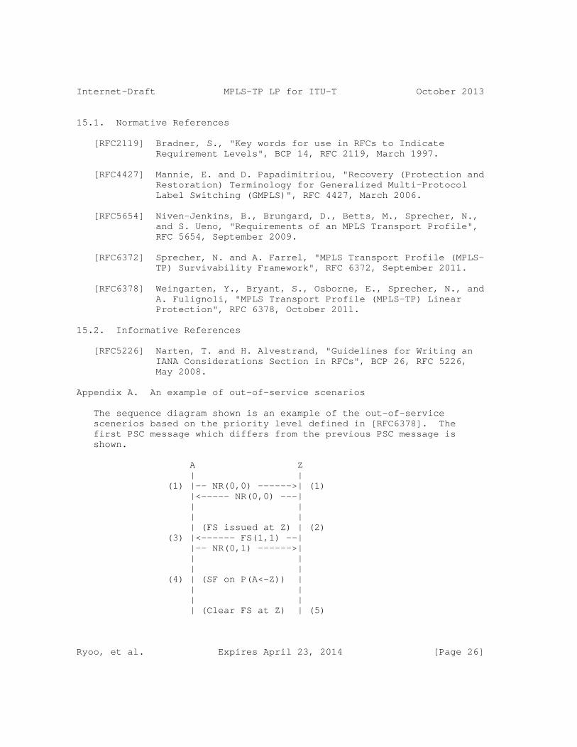
Internet-Draft MPLS-TP LP for ITU-T October 2013
15.1. Normative References
[RFC2119] Bradner, S., "Key words for use in RFCs to Indicate Requirement Levels", BCP 14, RFC 2119, March 1997.
[RFC4427] Mannie, E. and D. Papadimitriou, "Recovery (Protection and Restoration) Terminology for Generalized Multi-Protocol Label Switching (GMPLS)", RFC 4427, March 2006.
[RFC5654] Niven-Jenkins, B., Brungard, D., Betts, M., Sprecher, N., and S. Ueno, "Requirements of an MPLS Transport Profile", RFC 5654, September 2009.
[RFC6372] Sprecher, N. and A. Farrel, "MPLS Transport Profile (MPLS- TP) Survivability Framework", RFC 6372, September 2011.
[RFC6378] Weingarten, Y., Bryant, S., Osborne, E., Sprecher, N., and A. Fulignoli, "MPLS Transport Profile (MPLS-TP) Linear Protection", RFC 6378, October 2011.
15.2. Informative References
[RFC5226] Narten, T. and H. Alvestrand, "Guidelines for Writing an IANA Considerations Section in RFCs", BCP 26, RFC 5226, May 2008.
Appendix A. An example of out-of-service scenarios
The sequence diagram shown is an example of the out-of-service scenerios based on the priority level defined in [RFC6378]. The first PSC message which differs from the previous PSC message is shown.
A Z | | (1) |-- NR(0,0) ------>| (1) |<----- NR(0,0) ---| | | | | | (FS issued at Z) | (2) (3) |<------ FS(1,1) --| |-- NR(0,1) ------>| | | | | (4) | (SF on P(A<-Z)) | | | | | | (Clear FS at Z) | (5)
Ryoo, et al. Expires April 23, 2014 [Page 26]

Internet-Draft MPLS-TP LP for ITU-T October 2013
(6) | X <- NR(0,0) --| | | | |
(1) Each end is in Normal state, and transmits NR (0,0) messages.
(2) When a Forced Switch command is issued at node Z, node Z goes into local Protecting Administrative state (PA:F:L) and begins transmission of an FS (1,1) messages.
(3) A remote Forced Switch message causes node A to go into remote Protecting Administrative state (PA:F:R), and node A begins transmitting NR (0,1) messages.
(4) When node A detects a unidirectional Signal Fail on the Protection path, node A keeps sending NR (0,1) message because SF-P is ignored under the state PA:F:R.
(5) When a Clear command is issued at node Z, node Z goes into Normal state and begins transmission of NR (0,0) messages.
(6) But node A cannot receive PSC message because of local unidirectional Signal Fail on the Protection path. Because no valid PSC message is received, over a period of several successive message intervals, the last valid received message remains applicable and the node A continue to transmit an NR (0,1) message in the state of PA:F:R.
Now, there exists a mismatch between the bridge/selector positions of node A (transmitting an NR (0,1)) and node Z (transmitting an NR (0,0)). It results in out-of-service even when there is neither signal fail on working path nor FS.
Appendix B. An example of sequence diagram showing the problem with the priority level of Clear SF
An example of sequence diagram showing the problem with the priority level of Clear SF defined in [RFC6378] is given below. The following sequence diagram is depicted for the case of bidirectional signal fails. However, other cases with unidirectional signal fails can result in the same problem. The first PSC message which differs from the previous PSC message is shown.
A Z | | (1) |-- NR(0,0) ------>| (1) |<----- NR(0,0) ---|
Ryoo, et al. Expires April 23, 2014 [Page 27]

Internet-Draft MPLS-TP LP for ITU-T October 2013
| | | | (2) | (SF on P(A<->Z)) | (2) |-- SF(0,0) ------>| |<------ SF(0,0) --| | | | | (3) | (SF on W(A<->Z)) | (3) | | | | (4) | (Clear SF-P) | (4) | | | | (5) | (Clear SF-W) | (5) | | | |
(1) Each end is in Normal state, and transmits NR (0,0) messages.
(2) When signal fail on protection (SF-P) occurs, each node enters into [UA:P:L] state and transmits SF (0,0) messages. Traffic remains on working path.
(3) When signal fail on working (SF-W) occurs, each node remains in [UA:P:L] state as SF-W has a lower priority than SF-P. Traffic is still on the working path. Traffic cannot be delivered as both working and protection paths are experiencing signal fails.
(4) When the signal fail on protection is cleared, local "Clear SF-P" request cannot be presented to the PSC control logic, which takes the highest priority local request and runs PSC state machine, as the priority of "Clear SF-P" is lower than that of SF-W. Consequently, there is no change in state, and the selector and/or bridge keep pointing at the working path, which has signal fail condition.
Now, traffic cannot be delivered while the protection path is recovered and available. It should be noted that the same problem will occur in the case that the sequence of SF-P and SF-W events is changed.
If we further continue with this sequence to see what will happen after SF-W is cleared,
(5) When the signal fail on working is cleared, local "Clear SF-W" request can be passed to the PSC control logic (state machine) as there is no higher priority local request, but this will be ignored in the PSC control logic according to the state transition definition
Ryoo, et al. Expires April 23, 2014 [Page 28]

Internet-Draft MPLS-TP LP for ITU-T October 2013
in [RFC6378]. There will be no change in state or protocol message transmitted.
As the signal fail on working is now cleared and the selector and/or bridge are still pointing at the working path, traffic delivery is resumed. However, each node is in [UA:P:L] state and transmitting SF(0,0) message, while there exists no outstanding request for protection switching. Moreover, any future legitimate protection switching requests, such as SF-W, will be rejected as each node thinks the protection path is unavailable.
Appendix C. Freeze Command
The "Freeze" command applies only to the near end (local node) of the protection group and is not signalled to the far end. This command freezes the state of the protection group. Until the Freeze is cleared, additional near end commands are rejected and condition changes and received PSC information are ignored.
"Clear Freeze" command clears the local freeze. When the Freeze command is cleared, the state of the protection group is recomputed based on the persistent condition of the local triggers.
Because the freeze is local, if the freeze is issued at one end only, a failure of protocol can occur as the other end is open to accept any operator command or a fault condition.
Authors’ Addresses
Jeong-dong Ryoo (editor) ETRI 218 Gajeongno Yuseong-gu, Daejeon 305-700 South Korea
Phone: +82-42-860-5384 Email: [email protected]
Eric Gray (editor) Ericsson
Email: [email protected]
Ryoo, et al. Expires April 23, 2014 [Page 29]

Internet-Draft MPLS-TP LP for ITU-T October 2013
Huub van Helvoort Huawei Technologies Karspeldreef 4, Amsterdam 1101 CJ the Netherlands
Phone: +31 20 4300936 Email: [email protected]
Alessandro D’Alessandro Telecom Italia via Reiss Romoli, 274 Torino 10148 Italy
Phone: +39 011 2285887 Email: [email protected]
Taesik Cheung ETRI 218 Gajeongno Yuseong-gu, Daejeon 305-700 South Korea
Phone: +82-42-860-5646 Email: [email protected]
Eric Osborne Cisco Systems, Inc.
Email: [email protected]
Ryoo, et al. Expires April 23, 2014 [Page 30]

Network Working Group X. XuInternet-Draft HuaweiIntended status: Standards Track S. KiniExpires: March 10, 2014 Ericsson S. Sivabalan C. Filsfils Cisco September 06, 2013
Signaling Entropy Label Capability Using Interior Gateway Protocols draft-xu-mpls-el-capability-signaling-igp-00
Abstract
Multi Protocol Label Switching (MPLS) has defined a mechanism to load balance traffic flows using Entropy Labels (EL). An LSR inserts the EL Indicator and the EL label only if the LSR that pops them has the capability of processing them. This draft defines a mechanism to signal that capability using link state Interior Gateway Protocols (IGP). This mechanism is useful when the label advertisement is also done via that IGP.
Status of This Memo
This Internet-Draft is submitted in full conformance with the provisions of BCP 78 and BCP 79.
Internet-Drafts are working documents of the Internet Engineering Task Force (IETF). Note that other groups may also distribute working documents as Internet-Drafts. The list of current Internet- Drafts is at http://datatracker.ietf.org/drafts/current/.
Internet-Drafts are draft documents valid for a maximum of six months and may be updated, replaced, or obsoleted by other documents at any time. It is inappropriate to use Internet-Drafts as reference material or to cite them other than as "work in progress."
This Internet-Draft will expire on March 10, 2014.
Copyright Notice
Copyright (c) 2013 IETF Trust and the persons identified as the document authors. All rights reserved.
This document is subject to BCP 78 and the IETF Trust’s Legal Provisions Relating to IETF Documents (http://trustee.ietf.org/license-info) in effect on the date of
Xu, et al. Expires March 10, 2014 [Page 1]

Internet-Draft Signaling for EL Capability Using IGPs September 2013
publication of this document. Please review these documents carefully, as they describe your rights and restrictions with respect to this document. Code Components extracted from this document must include Simplified BSD License text as described in Section 4.e of the Trust Legal Provisions and are provided without warranty as described in the Simplified BSD License.
Table of Contents
1. Introduction . . . . . . . . . . . . . . . . . . . . . . . . 2 1.1. Requirements Language . . . . . . . . . . . . . . . . . . 2 2. Abbreviations and Terminology . . . . . . . . . . . . . . . . 3 3. Advertising ELC using OSPF . . . . . . . . . . . . . . . . . 3 4. Advertising ELC using ISIS . . . . . . . . . . . . . . . . . 3 5. Acknowledgements . . . . . . . . . . . . . . . . . . . . . . 3 6. IANA Considerations . . . . . . . . . . . . . . . . . . . . . 3 7. Security Considerations . . . . . . . . . . . . . . . . . . . 3 8. References . . . . . . . . . . . . . . . . . . . . . . . . . 3 8.1. Normative References . . . . . . . . . . . . . . . . . . 4 8.2. Informative References . . . . . . . . . . . . . . . . . 4 Authors’ Addresses . . . . . . . . . . . . . . . . . . . . . . . 4
1. Introduction
Multi Protocol Label Switching (MPLS) has defined a method in [RFC6790] to load balance traffic flows using Entropy Labels (EL). An LSR inserts the EL Indicator and the EL only if the LSR that pops those labels has the capability of recognizing and processing them. [RFC6790] defines the signaling of this capability (a.k.a Entropy Label Capability - ELC) via signaling protocols. Recently, mechanisms are being defined to signal labels via link state Interior Gateway Protocols (IGP) such as OSPF [I-D.psenak-ospf-segment-routing-extensions] and ISIS [I-D.previdi-isis-segment-routing-extensions]. In such scenarios the signaling mechanisms defined in [RFC6790] are inadequate. This draft defines mechanisms to signal the ELC using the link state advertisements (LSA) of the IGPs OSPF and ISIS. These capabilities are advertised for the entire router and not just a single prefix. This mechanism is useful when the label advertisement is also done via that IGP.
1.1. Requirements Language
The key words "MUST", "MUST NOT", "REQUIRED", "SHALL", "SHALL NOT", "SHOULD", "SHOULD NOT", "RECOMMENDED", "MAY", and "OPTIONAL" in this document are to be interpreted as described in RFC 2119 [RFC2119].
Xu, et al. Expires March 10, 2014 [Page 2]

Internet-Draft Signaling for EL Capability Using IGPs September 2013
2. Abbreviations and Terminology
This memo makes use of the terms defined in [RFC6790], [RFC4970] and [RFC4971].
3. Advertising ELC using OSPF
The OSPF Router Information (RI) Opaque LSA defined in [RFC4970] is used by OSPF routers to announce their capabilities. A new TLV within the body of this LSA, called ELC TLV is defined to advertise the capability of the router to process the ELI and EL. Its formatting follows that described in sec 2.1 of [RFC4970]. This TLV is applicable to both OSPFv2 and OSPFv3. The Type for the ELC TLV needs to be assigned by IANA and it has a Length of zero. The scope of the advertisement depends on the application but it is recommended that it SHOULD be AS-scoped.
4. Advertising ELC using ISIS
The IS-IS Router CAPABILITY TLV defined in [RFC4971] is used by IS-IS routers to announce their capabilities. A new sub-TLV of this TLV, called ELC sub-TLV is defined to advertise the capability of the router to process the ELI and EL. It is formatted as described in [RFC5305] with a Type code to be assigned by IANA and a Length of zero. The scope of the advertisement depends on the application but it is recommended that it SHOULD be domain-wide.
5. Acknowledgements
The authors would like to thank TBD for their comments.
6. IANA Considerations
This memo includes requests to IANA to allocate a TLV type from the OSPF RI TLVs registry and a sub-TLV type within the IS-IS Router Capability TLV.
7. Security Considerations
This document does not introduce any new security considerations.
8. References
Xu, et al. Expires March 10, 2014 [Page 3]

Internet-Draft Signaling for EL Capability Using IGPs September 2013
8.1. Normative References
[I-D.previdi-isis-segment-routing-extensions] Previdi, S., Filsfils, C., Bashandy, A., Gredler, H., and S. Litkowski, "IS-IS Extensions for Segment Routing", draft-previdi-isis-segment-routing-extensions-02 (work in progress), July 2013.
[I-D.psenak-ospf-segment-routing-extensions] Psenak, P., Previdi, S., Filsfils, C., Gredler, H., and R. Shakir, "OSPF Extensions for Segment Routing", draft- psenak-ospf-segment-routing-extensions-02 (work in progress), July 2013.
[RFC2119] Bradner, S., "Key words for use in RFCs to Indicate Requirement Levels", BCP 14, RFC 2119, March 1997.
[RFC4970] Lindem, A., Shen, N., Vasseur, JP., Aggarwal, R., and S. Shaffer, "Extensions to OSPF for Advertising Optional Router Capabilities", RFC 4970, July 2007.
[RFC4971] Vasseur, JP., Shen, N., and R. Aggarwal, "Intermediate System to Intermediate System (IS-IS) Extensions for Advertising Router Information", RFC 4971, July 2007.
[RFC5305] Li, T. and H. Smit, "IS-IS Extensions for Traffic Engineering", RFC 5305, October 2008.
[RFC6790] Kompella, K., Drake, J., Amante, S., Henderickx, W., and L. Yong, "The Use of Entropy Labels in MPLS Forwarding", RFC 6790, November 2012.
8.2. Informative References
[I-D.filsfils-rtgwg-segment-routing] Filsfils, C., Previdi, S., Bashandy, A., Decraene, B., Litkowski, S., Horneffer, M., Milojevic, I., Shakir, R., Ytti, S., Henderickx, W., Tantsura, J., and E. Crabbe, "Segment Routing Architecture", draft-filsfils-rtgwg- segment-routing-00 (work in progress), June 2013.
Authors’ Addresses
Xiaohu Xu Huawei
Email: [email protected]
Xu, et al. Expires March 10, 2014 [Page 4]

Internet-Draft Signaling for EL Capability Using IGPs September 2013
Sriganesh Kini Ericsson
Email: [email protected]
Siva Sivabalan Cisco
Email: [email protected]
Clarence Filsfils Cisco
Email: [email protected]
Xu, et al. Expires March 10, 2014 [Page 5]

Network working group X. XuInternet Draft Z. LiCategory: Informational Huawei
Expires: April 2014 October 17, 2013
Multi-domain MPLS Deployment Enhancement
draft-xu-mpls-multi-domain-deployment-enhancement-00
Abstract
MPLS as a mature technology is increasingly deployed in large-scale networks which consists of multiple domains (e.g., IGP areas/levels and even Autonomous Systems). To scale such multi-domain MPLS deployment, the concept of hierarchical LSPs is usually resorted. This document describes an enhancement to such hierarchical multi- domain MPLS deployment architecture that could further improve the scalability of multi-domain MPLS deployment.
Status of this Memo
This Internet-Draft is submitted in full conformance with the provisions of BCP 78 and BCP 79.
Internet-Drafts are working documents of the Internet Engineering Task Force (IETF). Note that other groups may also distribute working documents as Internet-Drafts. The list of current Internet- Drafts is at http://datatracker.ietf.org/drafts/current/.
Internet-Drafts are draft documents valid for a maximum of six months and may be updated, replaced, or obsoleted by other documents at any time. It is inappropriate to use Internet-Drafts as reference material or to cite them other than as "work in progress."
This Internet-Draft will expire on April 17, 2014.
Copyright Notice
Copyright (c) 2013 IETF Trust and the persons identified as the document authors. All rights reserved.
This document is subject to BCP 78 and the IETF Trust’s Legal Provisions Relating to IETF Documents (http://trustee.ietf.org/license-info) in effect on the date of publication of this document. Please review these documents
Xu, et al. Expires April 17, 2014 [Page 1]

Internet-Draft Multi-domain MPLS Deployment Enhancement October 2013
carefully, as they describe your rights and restrictions with respect to this document. Code Components extracted from this document must include Simplified BSD License text as described in Section 4.e of the Trust Legal Provisions and are provided without warranty as described in the Simplified BSD License.
Conventions used in this document
The key words "MUST", "MUST NOT", "REQUIRED", "SHALL", "SHALL NOT", "SHOULD", "SHOULD NOT", "RECOMMENDED", "MAY", and "OPTIONAL" in this document are to be interpreted as described in RFC-2119 [RFC2119].
Table of Contents
1. Introduction ................................................ 3 2. Terminology ................................................. 3 3. Deployment Enhancement ...................................... 3 4. Conclusions ................................................. 5 5. Security Considerations...................................... 5 6. IANA Considerations ......................................... 5 7. Acknowledgements ............................................ 5 8. References .................................................. 5 8.1. Normative References ................................... 5 8.2. Informative References ................................. 5 Authors’ Addresses ............................................. 6
Xu, et al. Expires April 17, 2014 [Page 2]

Internet-Draft Multi-domain MPLS Deployment Enhancement October 2013
1. Introduction
MPLS as a mature technology is increasingly deployed in large-scale networks which consists of multiple IGP areas/levels and even multiple Autonomous Systems (AS’s) (e.g., Inter-AS L3VPN option C described in [RFC4364]). For simplicity, in the rest of this document the term "domain" would be used to refer area/level/AS. To scale such multi-domain MPLS deployment, the concept of hierarchical LSPs is usually resorted. The basic idea behind this concept is the innermost transport LSP which is across domain boundaries is actually transported over multiple outer transport LSPs which are confined within each domain (a.k.a., originated and terminated within the same domain). Such a hierarchical routing and forwarding concept allows exchange of loopback addresses and MPLS label bindings for innermost transport LSPs across these domains while preventing the above information from being flooded into domains or parts of the network that do not need them. In most cases, the innermost transport LSPs are established primarily using labeled BGP [RFC3107]. In some special cases (e.g., seamless MPLS [Seamless-MPLS]), the innermost transport LSP could also be a stitched LSP of BGP-signaled LSPs and LDP-signaled LSPs.
Such a hierarchical routing and forwarding concept has greatly improved the scalability of the multi-domain MPLS deployment. However, in the case where the number of PE routers is enormous, a large amount of non-aggregatable labeled BGP routes for those PE routers would have to be advertised across domain boundaries. As stated in the seamless MPLS draft [Seamless-MPLS], "...this architecture results in carrying all loopbacks of all nodes except pure P nodes (AN, AGN, ABR and core PE) in labeled BGP, e.g., there will be in the order of 100,000 routes in labeled BGP when approaching the stated scalability goal..." Without special implementation and configuration, it would result in tremendous and unnecessary consumption of the BGP RIB and even MPLS forwarding table resources on domain boundary nodes (e.g., ABRs). Therefore, there is still room for improvement in scalability.
2. Terminology
This memo makes use of the terms defined in [RFC3031] and [RFC3107].
3. Deployment Enhancement
In the hierarchical LSP case as mentioned in Section 1, the innermost transport LSP only represents a logical connectivity to the final tunnel endpoint (e.g., egress PE routers). As such, it’s no problem to replace such innermost transport LSP with an IP tunnel while
Xu, et al. Expires April 17, 2014 [Page 3]

Internet-Draft Multi-domain MPLS Deployment Enhancement October 2013
keeping the remaining outer MPLS LSPs unchanged. In this way, there is no need for advertising no-aggregatable labeled BGP host routes across domain boundaries anymore. Instead, it only requires advertising aggregated non-labeled BGP routes across domain boundaries.
To clearly understand the concept of the multi-domain MPLS deployment enhancement as suggested above, a multi-area MPLS deployment example with enhancement is illustrated as follows:
/----\ /-------\ /----\ /// \\\\ /// \\\ //// \\\\ +----+ +-----+ +-----+ +----+ |PE-1| OSPF Area 1 |ABR-1| OSPF Area 0 |ABR-2| OSPF Area 2 |PE-2| +----+ +-----+ +-----+ +----+ \\\\ //// \\\ /// \\\\ //// \----/ \-------/ \----/
|<--------------------------IP Tunnel------------------------>|
|<------LSP-------->|<--------LSP-------->|<--------LSP------>|
In the above example, iBGP sessions are established between PEs (i.e., PE-1 and PE-2) and ABRs (e.g., ABR-1 and ABR-2). Assume loopback addresses of all PEs within area 1 are within 10.1.0.0/16 while loopback addresses of all PEs within area 2 are within 10.2.0.0/16. ABR1 would advertise a route for 10.1.0.0/16 to ABR-2 which in turn advertises that route upon receiving to PE-2. Similarly, ABR-2 would advertise a route for 10.2.0.0/16 to ABR-1 which in turn advertises that route upon receiving to PE-1. In addition, intra-domain LSPs have been established between PEs and ABRs.
Assume PE-1 needs to send a packet P1 to PE-2, PE-1 would encapsulate such packet into an IP tunnel with tunnel source of PE-1’s loopback address and tunnel destination of PE-2’s loopback address. For example, if the packet is a MPLS IP VPN packet, the packet would be encapsulated using any IP-based encapsulation method for MPLS (e.g., MPLS-in-IP). PE-1 then performs IP forwarding lookup for the encapsulated packet P2. Since the BGP next-hop of the best route (i.e., 10.2.0.0/16) for the packet P2’s destination (i.e., PE-2’s loopback address) is ABR-1 and PE-1 has a LSP towards ABR-1, PE-1 therefore would transport that encapsulated packet P2 over that LSP. Upon receipt of that encapsulated packet P2 via that LSP, ABR-1 would in turn perform IP forwarding lookup for the encapsulated packet P2. Since the BGP next-hop of the best route for that packet is ABR-2 and ABR1 has a LSP towards ABR-2, ABR-1 would transport that encapsulated packet P2 via the LSP towards ABR-2. When that encapsulated packet P2
Xu, et al. Expires April 17, 2014 [Page 4]

Internet-Draft Multi-domain MPLS Deployment Enhancement October 2013
arrives at ABR-2, ABR-2 would also perform IP forwarding lookup and then forward that packet P2 via a LSP towards PE-2. PE-2 decapsulates the received packet P2 and then process the resulting decapsualted packet P1 accordingly.
4. Conclusions
By simply replacing the innermost transport LSP with an IP tunnel, the need for advertising non-aggregatable BGP labeled host routes across domains is eliminated. Instead, it only requires advertising aggregated non-labeled BGP routes across domains. As a result, the requirement for BGP RIB and MPLS forwarding table resources are largely reduced. Furthermore, in the multi-area/level MPLS deployment case where MPLS-TE shortcut or Forwarding Adjacency (FA) feature is enabled between ABRs, the need for running BGP between ABRs can be eliminated further. Instead, IGP route summary across area boundaries is good enough.
5. Security Considerations
TBD.
6. IANA Considerations
No action is required for IANA.
7. Acknowledgements
Thanks to.
8. References
8.1. Normative References
[RFC2119] Bradner, S., "Key words for use in RFCs to Indicate Requirement Levels", BCP 14, RFC 2119, March 1997.
[RFC3031] Rosen, E., Viswanathan, A. and R. Callon, "Multiprotocol Label Switching Architecture", RFC 3031, January 2001.
[RFC4023] Worster, T., Rekhter, Y., and E. Rosen, "Encapsulating MPLS in IP or GRE", RFC4023, March 2005.
8.2. Informative References
[RFC3107] Rekhter, Y. and E. Rosen, "Carrying Label Information in BGP-4", RFC 3107, May 2001.
Xu, et al. Expires April 17, 2014 [Page 5]

Internet-Draft Multi-domain MPLS Deployment Enhancement October 2013
[RFC4364] Rosen. E and Y. Rekhter, "BGP/MPLS IP Virtual Private Networks (VPNs)", RFC 4364, February 2006.
[Seamless-MPLS] Leymann, N., Decraene, B., Filsfils, C., Konstantynowicz, M., and D. Steinberg, "Seamless MPLS Architecture", draft-ietf-mpls-seamless-mpls-04(Work in Progress), July 2013.
Authors’ Addresses
Xiaohu Xu Huawei Technologies, Beijing, China Phone: +86-10-60610041 Email: [email protected]
Zhenbin Li Huawei Technologies, Beijing, China Phone: +86-10-60613676 Email: [email protected]