lab configuring per-interface inter-vlan routingmetalab.uniten.edu.my/~rina/csnb214/lab/lab 4 -...
TRANSCRIPT
CSNB214 Packet Tracer
© 2017 Cisco and/or its affiliates. All rights reserved. This document is Cisco Public. Page 1 of 7
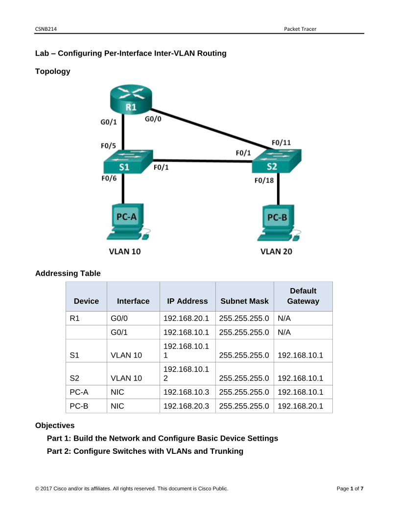
Lab – Configuring Per-Interface Inter-VLAN Routing
Topology
Addressing Table
Device Interface IP Address Subnet Mask
Default
Gateway
R1 G0/0 192.168.20.1 255.255.255.0 N/A
G0/1 192.168.10.1 255.255.255.0 N/A
S1 VLAN 10 192.168.10.11 255.255.255.0 192.168.10.1
S2 VLAN 10 192.168.10.12 255.255.255.0 192.168.10.1
PC-A NIC 192.168.10.3 255.255.255.0 192.168.10.1
PC-B NIC 192.168.20.3 255.255.255.0 192.168.20.1
Objectives
Part 1: Build the Network and Configure Basic Device Settings
Part 2: Configure Switches with VLANs and Trunking
Lab – Configuring Per-Interface Inter-VLAN Routing
© 2017 Cisco and/or its affiliates. All rights reserved. This document is Cisco Public.
Edited by MarinaMD to suit the syllabus of 2017 Page 2 of 7
Part 3: Verify Trunking, VLANs, Routing, and Connectivity
Background / Scenario
Legacy inter-VLAN routing is seldom used in today’s networks; however, it is helpful to configure and understand this type of routing before moving on to router-on-a-stick (trunk-based) inter-VLAN routing or configuring Layer-3 switching. Also, you may encounter per-interface inter-VLAN routing in organizations with very small networks. One of the benefits of legacy inter-VLAN routing is ease of configuration.
In this lab, you will set up one router with two switches attached via the router Gigabit Ethernet interfaces. Two separate VLANs will be configured on the switches, and you will set up routing between the VLANs.
Note: This lab provides minimal assistance with the actual commands necessary to configure the router and switches. The required switch VLAN configuration commands are provided in Appendix A of this lab. Test your knowledge by trying to configure the devices without referring to the appendix.
Note: The routers used with CCNA hands-on labs are Cisco 1941 Integrated Services Routers (ISRs) with Cisco IOS, Release 15.2(4). The switches used are Cisco Catalyst 2960s with Cisco IOS, Release 15.0(2). Other routers, switches and Cisco IOS versions can be used. Depending on the model and Cisco IOS version, the commands available and output produced might vary from what is shown in the labs. Refer to the Router Interface Summary Table at the end of this lab for the correct interface identifiers.
Note: Make sure that the routers and switches have been erased and have no startup configurations. If you are unsure, contact your instructor.
Required Resources
1 Router (Cisco 1941 with Cisco IOS Release 15.2(4) or comparable)
2 Switches (Cisco 2960 with Cisco IOS Release 15.0(2) or comparable)
2 PCs (Windows 7, Vista, or XP with terminal emulation program, such as Tera Term)
Console cables to configure the Cisco IOS devices via the console ports
Ethernet cables as shown in the topology
Part 1: Build the Network and Configure Basic Device Settings
In Part 1, you will set up the network topology and clear any configurations, if necessary.
Step 1: Cable the network as shown in the topology.
Step 2: Initialize and reload the router and switches.
Step 3: Configure basic settings for R1.
a. Console into R1 and enter global configuration mode.
b. Copy the following basic configuration and paste it to the running-configuration on R1.
Lab – Configuring Per-Interface Inter-VLAN Routing
© 2017 Cisco and/or its affiliates. All rights reserved. This document is Cisco Public.
Edited by MarinaMD to suit the syllabus of 2017 Page 3 of 7
no ip domain-lookup
hostname R1
service password-encryption
enable secret class
banner motd #
Unauthorized access is strictly prohibited. #
line con 0
password cisco
login
logging synchronous
line vty 0 4
password cisco
login
c. Configure addressing on G0/0 and G0/1 and enable both interfaces.
d. Copy the running configuration to the startup configuration.
Step 4: Configure basic settings on both switches.
a. Console into the switch and enter global configuration mode.
b. Copy the following basic configuration and paste it to running-configuration on the switch.
no ip domain-lookup
service password-encryption
enable secret class
banner motd #
Unauthorized access is strictly prohibited. #
Line con 0
password cisco
login
logging synchronous
line vty 0 15
password cisco
login
exit
c. Configure the host name as shown in the topology.
d. Copy the running configuration to the startup configuration.
Lab – Configuring Per-Interface Inter-VLAN Routing
© 2017 Cisco and/or its affiliates. All rights reserved. This document is Cisco Public.
Edited by MarinaMD to suit the syllabus of 2017 Page 4 of 7
Step 5: Configure basic settings on PC-A and PC-B.
Configure PC-A and PC-B with IP addresses and a default gateway address according to the Addressing Table.
Part 2: Configure Switches with VLANs and Trunking
In Part 2, you will configure the switches with VLANs and trunking.
Step 1: Configure VLANs on S1.
a. On S1, create VLAN 10. Assign Student as the VLAN name.
b. Create VLAN 20. Assign Faculty-Admin as the VLAN name.
c. Configure F0/1 as a trunk port.
d. Assign ports F0/5 and F0/6 to VLAN 10 and configure both F0/5 and F0/6 as access ports.
e. Assign an IP address to VLAN 10 and enable it. Refer to the Addressing Table.
f. Configure the default gateway according to the Addressing Table.
Step 2: Configure VLANs on S2.
a. On S2, create VLAN 10. Assign Student as the VLAN name.
b. Create VLAN 20. Assign Faculty-Admin as the VLAN name.
c. Configure F0/1 as a trunk port.
d. Assign ports F0/11 and F0/18 to VLAN 20 and configure both F0/11 and F0/18 as access ports.
e. Assign an IP address to VLAN 10 and enable it. Refer to the Addressing Table.
f. Configure the default gateway according to the Addressing Table.
Part 3: Verify Trunking, VLANs, Routing, and Connectivity
Step 1: Verify the R1 routing table.
a. On R1, issue the show ip route command. What routes are listed on R1?
______________________________________________________________________
______________________________________________________________________
b. On both S1 and S2, issue the show interface trunk command. Is the F0/1 port on both switches set to trunk? ______
c. Issue a show vlan brief command on both S1 and S2. Verify that VLANs 10 and 20 are active and that the proper ports on the switches are in the correct VLANs. Why is F0/1 not listed in any of the active VLANs?
______________________________________________________________________
Lab – Configuring Per-Interface Inter-VLAN Routing
© 2017 Cisco and/or its affiliates. All rights reserved. This document is Cisco Public.
Edited by MarinaMD to suit the syllabus of 2017 Page 5 of 7
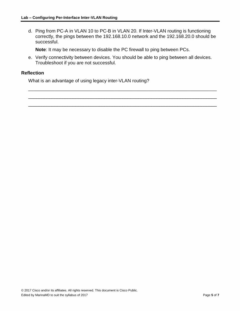
d. Ping from PC-A in VLAN 10 to PC-B in VLAN 20. If Inter-VLAN routing is functioning correctly, the pings between the 192.168.10.0 network and the 192.168.20.0 should be successful.
Note: It may be necessary to disable the PC firewall to ping between PCs.
e. Verify connectivity between devices. You should be able to ping between all devices. Troubleshoot if you are not successful.
Reflection
What is an advantage of using legacy inter-VLAN routing?
________________________________________________________________________
________________________________________________________________________
________________________________________________________________________
Lab – Configuring Per-Interface Inter-VLAN Routing
© 2017 Cisco and/or its affiliates. All rights reserved. This document is Cisco Public.
Edited by MarinaMD to suit the syllabus of 2017 Page 6 of 7
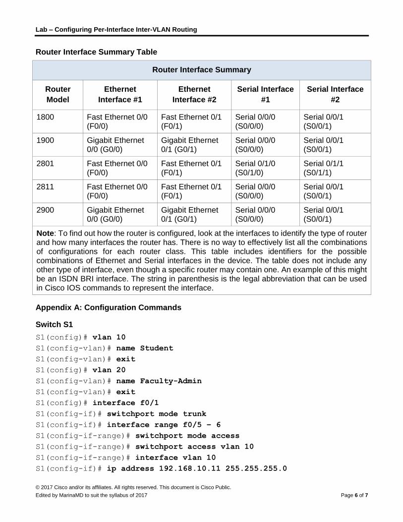
Router Interface Summary Table
Router Interface Summary
Router
Model
Ethernet
Interface #1
Ethernet
Interface #2
Serial Interface
#1
Serial Interface
#2
1800 Fast Ethernet 0/0 (F0/0)
Fast Ethernet 0/1 (F0/1)
Serial 0/0/0 (S0/0/0)
Serial 0/0/1 (S0/0/1)
1900 Gigabit Ethernet 0/0 (G0/0)
Gigabit Ethernet 0/1 (G0/1)
Serial 0/0/0 (S0/0/0)
Serial 0/0/1 (S0/0/1)
2801 Fast Ethernet 0/0 (F0/0)
Fast Ethernet 0/1 (F0/1)
Serial 0/1/0 (S0/1/0)
Serial 0/1/1 (S0/1/1)
2811 Fast Ethernet 0/0 (F0/0)
Fast Ethernet 0/1 (F0/1)
Serial 0/0/0 (S0/0/0)
Serial 0/0/1 (S0/0/1)
2900 Gigabit Ethernet 0/0 (G0/0)
Gigabit Ethernet 0/1 (G0/1)
Serial 0/0/0 (S0/0/0)
Serial 0/0/1 (S0/0/1)
Note: To find out how the router is configured, look at the interfaces to identify the type of router and how many interfaces the router has. There is no way to effectively list all the combinations of configurations for each router class. This table includes identifiers for the possible combinations of Ethernet and Serial interfaces in the device. The table does not include any other type of interface, even though a specific router may contain one. An example of this might be an ISDN BRI interface. The string in parenthesis is the legal abbreviation that can be used in Cisco IOS commands to represent the interface.
Appendix A: Configuration Commands
Switch S1
S1(config)# vlan 10
S1(config-vlan)# name Student
S1(config-vlan)# exit
S1(config)# vlan 20
S1(config-vlan)# name Faculty-Admin
S1(config-vlan)# exit
S1(config)# interface f0/1
S1(config-if)# switchport mode trunk
S1(config-if)# interface range f0/5 – 6
S1(config-if-range)# switchport mode access
S1(config-if-range)# switchport access vlan 10
S1(config-if-range)# interface vlan 10
S1(config-if)# ip address 192.168.10.11 255.255.255.0
Lab – Configuring Per-Interface Inter-VLAN Routing
© 2017 Cisco and/or its affiliates. All rights reserved. This document is Cisco Public.
Edited by MarinaMD to suit the syllabus of 2017 Page 7 of 7
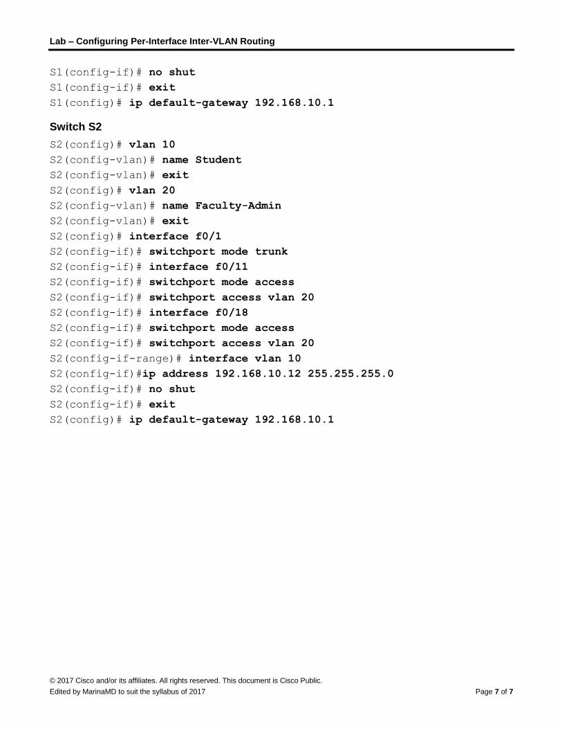
S1(config-if)# no shut
S1(config-if)# exit
S1(config)# ip default-gateway 192.168.10.1
Switch S2
S2(config)# vlan 10
S2(config-vlan)# name Student
S2(config-vlan)# exit
S2(config)# vlan 20
S2(config-vlan)# name Faculty-Admin
S2(config-vlan)# exit
S2(config)# interface f0/1
S2(config-if)# switchport mode trunk
S2(config-if)# interface f0/11
S2(config-if)# switchport mode access
S2(config-if)# switchport access vlan 20
S2(config-if)# interface f0/18
S2(config-if)# switchport mode access
S2(config-if)# switchport access vlan 20
S2(config-if-range)# interface vlan 10
S2(config-if)#ip address 192.168.10.12 255.255.255.0
S2(config-if)# no shut
S2(config-if)# exit
S2(config)# ip default-gateway 192.168.10.1