kyocera mita km 6330 7530 service manual
TRANSCRIPT

SERVICEMANUAL
Published in Sept. ’032CJ70762Revision 2
KM-6330KM-7530

CAUTION
DANGER OF EXPLOSION IF BATTERY IS INCORRECTLY REPLACED. REPLACE ONLY WITHTHE SAME OR EQUIVALENT TYPE RECOMMENDED BY THE MANUFACTURER. DISPOSE OFUSED BATTERIES ACCORDING TO THE MANUFACTURER’S INSTRUCTIONS.
ATTENTION
IL Y A DANGER D’EXPLOSION S’IL Y A REMPLACEMENT INCORRECT DE LA BATTERIE.REMPLACER UNIQUEMENT AVEC UNE BATTERIE DU MÊME TYPE OU D’UN TYPE REC-OMMANDÉ PAR LE CONSTRUCTEUR. METTRE AU RÉBUT LES BATTERIES USAGÉESCONFORMÉMENT AUX INSTRUCTIONS DU FABRICANT.

Safety precautions
This booklet provides safety warnings and precautions for our service personnel to ensure the safety oftheir customers, their machines as well as themselves during maintenance activities. Service personnelare advised to read this booklet carefully to familiarize themselves with the warnings and precautionsdescribed here before engaging in maintenance activities.
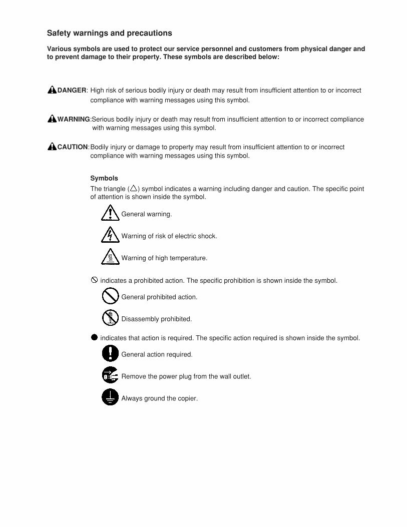
indicates that action is required. The specific action required is shown inside the symbol.
General action required.
Remove the power plug from the wall outlet.
Always ground the copier.
Safety warnings and precautions
Various symbols are used to protect our service personnel and customers from physical danger andto prevent damage to their property. These symbols are described below:
DANGER: High risk of serious bodily injury or death may result from insufficient attention to or incorrect
compliance with warning messages using this symbol.
WARNING:Serious bodily injury or death may result from insufficient attention to or incorrect compliancewith warning messages using this symbol.
CAUTION:Bodily injury or damage to property may result from insufficient attention to or incorrectcompliance with warning messages using this symbol.
Symbols
The triangle ( ) symbol indicates a warning including danger and caution. The specific pointof attention is shown inside the symbol.
General warning.
Warning of risk of electric shock.
Warning of high temperature.
indicates a prohibited action. The specific prohibition is shown inside the symbol.
General prohibited action.
Disassembly prohibited.
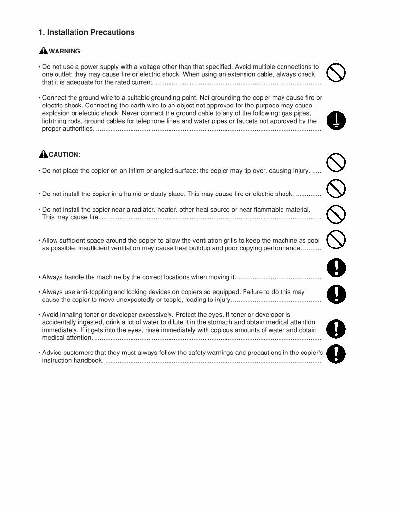
1. Installation Precautions
WARNING
• Do not use a power supply with a voltage other than that specified. Avoid multiple connections toone outlet: they may cause fire or electric shock. When using an extension cable, always checkthat it is adequate for the rated current. ............................................................................................
• Connect the ground wire to a suitable grounding point. Not grounding the copier may cause fire orelectric shock. Connecting the earth wire to an object not approved for the purpose may causeexplosion or electric shock. Never connect the ground cable to any of the following: gas pipes,lightning rods, ground cables for telephone lines and water pipes or faucets not approved by theproper authorities. .............................................................................................................................
CAUTION:
• Do not place the copier on an infirm or angled surface: the copier may tip over, causing injury. .....
• Do not install the copier in a humid or dusty place. This may cause fire or electric shock. ..............
• Do not install the copier near a radiator, heater, other heat source or near flammable material.This may cause fire. ..........................................................................................................................
• Allow sufficient space around the copier to allow the ventilation grills to keep the machine as coolas possible. Insufficient ventilation may cause heat buildup and poor copying performance. ..........
• Always handle the machine by the correct locations when moving it. ..............................................
• Always use anti-toppling and locking devices on copiers so equipped. Failure to do this maycause the copier to move unexpectedly or topple, leading to injury. .................................................
• Avoid inhaling toner or developer excessively. Protect the eyes. If toner or developer isaccidentally ingested, drink a lot of water to dilute it in the stomach and obtain medical attentionimmediately. If it gets into the eyes, rinse immediately with copious amounts of water and obtainmedical attention. ..............................................................................................................................
• Advice customers that they must always follow the safety warnings and precautions in the copier’sinstruction handbook. ........................................................................................................................
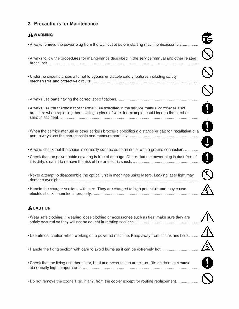
• Check that the power cable covering is free of damage. Check that the power plug is dust-free. Ifit is dirty, clean it to remove the risk of fire or electric shock. ............................................................
• Never attempt to disassemble the optical unit in machines using lasers. Leaking laser light maydamage eyesight. ..............................................................................................................................
• Handle the charger sections with care. They are charged to high potentials and may causeelectric shock if handled improperly. .................................................................................................
CAUTION
• Wear safe clothing. If wearing loose clothing or accessories such as ties, make sure they aresafely secured so they will not be caught in rotating sections...........................................................
• Use utmost caution when working on a powered machine. Keep away from chains and belts. .......
• Handle the fixing section with care to avoid burns as it can be extremely hot. .................................
• Check that the fixing unit thermistor, heat and press rollers are clean. Dirt on them can causeabnormally high temperatures. ..........................................................................................................
• Do not remove the ozone filter, if any, from the copier except for routine replacement. ...................
2. Precautions for Maintenance
WARNING
• Always remove the power plug from the wall outlet before starting machine disassembly. ..............
• Always follow the procedures for maintenance described in the service manual and other relatedbrochures. .........................................................................................................................................
• Under no circumstances attempt to bypass or disable safety features including safetymechanisms and protective circuits. .................................................................................................
• Always use parts having the correct specifications. ..........................................................................
• Always use the thermostat or thermal fuse specified in the service manual or other relatedbrochure when replacing them. Using a piece of wire, for example, could lead to fire or otherserious accident. ...............................................................................................................................
• When the service manual or other serious brochure specifies a distance or gap for installation of apart, always use the correct scale and measure carefully. ...............................................................
• Always check that the copier is correctly connected to an outlet with a ground connection. ............
• Do not pull on the AC power cord or connector wires on high-voltage components when removingthem; always hold the plug itself. ......................................................................................................
• Do not route the power cable where it may be stood on or trapped. If necessary, protect it with acable cover or other appropriate item. ..............................................................................................
• Treat the ends of the wire carefully when installing a new charger wire to avoid electric leaks........
• Remove toner completely from electronic components. ...................................................................
• Run wire harnesses carefully so that wires will not be trapped or damaged. ...................................
• After maintenance, always check that all the parts, screws, connectors and wires that wereremoved, have been refitted correctly. Special attention should be paid to any forgottenconnector, trapped wire and missing screws. ..................................................................................
• Check that all the caution labels that should be present on the machine according to theinstruction handbook are clean and not peeling. Replace with new ones if necessary. ...................
• Handle greases and solvents with care by following the instructions below: ....................................· Use only a small amount of solvent at a time, being careful not to spill. Wipe spills off completely.· Ventilate the room well while using grease or solvents.· Allow applied solvents to evaporate completely before refitting the covers or turning the main
switch on.· Always wash hands afterwards.
• Never dispose of toner or toner bottles in fire. Toner may cause sparks when exposed directly tofire in a furnace, etc. ..........................................................................................................................
• Should smoke be seen coming from the copier, remove the power plug from the wall outletimmediately. ......................................................................................................................................
3. Miscellaneous
WARNING
• Never attempt to heat the drum or expose it to any organic solvents such as alcohol, other thanthe specified refiner; it may generate toxic gas. ................................................................................
1-1-1
2CJ/2FA-2
CONTENTS
1-1 Specifications1-1-1 Specifications ....................................................................................................................................... 1-1-11-1-2 Parts names and their functions ........................................................................................................... 1-1-3
(1) Copier ............................................................................................................................................. 1-1-3(2) Operation panel .............................................................................................................................. 1-1-4
1-1-3 Machine cross section .......................................................................................................................... 1-1-51-1-4 Drive system ........................................................................................................................................ 1-1-6
(1) Drive system 1 (optical section) ...................................................................................................... 1-1-6(2) Drive system 2 (paper feed motor drive train) ................................................................................ 1-1-7(3) Drive system 3 (image forming motor drive train) ........................................................................... 1-1-8(4) Drive system 4 (drive motor drive train) .......................................................................................... 1-1-9(5) Drive system 5 (large paper deck) ................................................................................................ 1-1-10(6) Drive system 6 (duplex section) ................................................................................................... 1-1-11(7) Drive system 7 (document processor) .......................................................................................... 1-1-12
1-2 Handling Precautions1-2-1 Drum .................................................................................................................................................... 1-2-11-2-2 Developer and toner ............................................................................................................................. 1-2-11-2-3 Installation environment ....................................................................................................................... 1-2-1
1-3 Installation1-3-1 Unpacking and installation ................................................................................................................... 1-3-1
(1) Installation procedure ..................................................................................................................... 1-3-11-3-2 Setting initial copy modes .................................................................................................................. 1-3-161-3-3 Installing the key counter (option) ...................................................................................................... 1-3-171-3-4 Installing the cassette heater (option) ................................................................................................ 1-3-191-3-5 Installing the multi finisher (option) ..................................................................................................... 1-3-201-3-6 Installing the side deck (option) .......................................................................................................... 1-3-301-3-7 Installing the printing system (option) ................................................................................................. 1-3-341-3-8 Installing the scanning system (option) .............................................................................................. 1-3-361-3-9 Installing the tandem kit (option) ........................................................................................................ 1-3-38
1-4 Maintenance Mode1-4-1 Copier management ............................................................................................................................. 1-4-1
(1) Using the copier management mode .............................................................................................. 1-4-1(2) Setting department management items .......................................................................................... 1-4-2(3) Weekly timer ................................................................................................................................... 1-4-2(4) Copy default ................................................................................................................................... 1-4-3(5) Machine default .............................................................................................................................. 1-4-5(6) Bypass Setting ................................................................................................................................ 1-4-6(7) Document management default setting .......................................................................................... 1-4-6(8) Hard disk management .................................................................................................................. 1-4-7(9) Report ............................................................................................................................................. 1-4-7
(10) Language ........................................................................................................................................ 1-4-71-4-2 Maintenance mode ............................................................................................................................... 1-4-8
(1) Executing a maintenance item ....................................................................................................... 1-4-8(2) Maintenance mode item list ............................................................................................................ 1-4-9(3) Contents of maintenance mode items .......................................................................................... 1-4-13
1-5 Troubleshooting1-5-1 Paper misfeed detection ...................................................................................................................... 1-5-1
(1) Paper misfeed indication ................................................................................................................ 1-5-1(2) Paper misfeed detection conditions ................................................................................................ 1-5-2(3) Paper misfeeds ............................................................................................................................... 1-5-9
1-5-2 Self-diagnosis ..................................................................................................................................... 1-5-19(1) Self-diagnostic function ................................................................................................................ 1-5-19(2) Self-diagnostic codes ................................................................................................................... 1-5-20
1-1-2
2CJ/2FA-2
1-5-3 Image formation problems ................................................................................................................. 1-5-36(1) No image appears (entirely white). ............................................................................................... 1-5-38(2) No image appears (entirely black). ............................................................................................... 1-5-38(3) Image is too light. ......................................................................................................................... 1-5-39(4) Background is visible. ................................................................................................................... 1-5-39(5) A white line appears longitudinally. .............................................................................................. 1-5-39(6) A black line appears longitudinally. .............................................................................................. 1-5-40(7) A black line appears laterally. ....................................................................................................... 1-5-40(8) One side of the copy image is darker than the other. ................................................................... 1-5-40(9) Black dots appear on the image. .................................................................................................. 1-5-41
(10) Image is blurred. ........................................................................................................................... 1-5-41(11) The leading edge of the image is consistently misaligned with the original. ................................ 1-5-41(12) The leading edge of the image is sporadically misaligned with the original. ................................ 1-5-42(13) Paper creases. ............................................................................................................................. 1-5-42(14) Offset occurs. ............................................................................................................................... 1-5-42(15) Image is partly missing. ................................................................................................................ 1-5-43(16) Fixing is poor. ............................................................................................................................... 1-5-43(17) Image is out of focus. ................................................................................................................... 1-5-43(18) Image center does not align with the original center. ................................................................... 1-5-43(19) Image is not square. ..................................................................................................................... 1-5-44(20) Image contrast is low (carrier scattering) ...................................................................................... 1-5-44(21) When the large paper deck is used, the center of the original image
and that of the copy image do not align. ....................................................................................... 1-5-44(22) There is a regular error between the centers of the original and copy image
when the document processor is used. ........................................................................................ 1-5-45(23) There is a regular error between the leading edges of
the original and copy image when the document processor is used. ........................................... 1-5-451-5-4 Electrical problems ............................................................................................................................. 1-5-46
• Copier(1) The machine does not operate when the main switch is turned on. ............................................. 1-5-46(2) The image forming motor does not operate (C2000). .................................................................. 1-5-46(3) The drive motor does not operate (C2550). ................................................................................. 1-5-46(4) Paper feed motor does not operate (C2500). ............................................................................... 1-5-46(5) The scanner motor does not operate. .......................................................................................... 1-5-47(6) The duplex fan motor does not operate. ....................................................................................... 1-5-47(7) The optical section motor does not operate. ................................................................................ 1-5-47(8) The cooling fan motor does not operate. ...................................................................................... 1-5-47(9) The fixing unit fan motor does not operate. .................................................................................. 1-5-47
(10) LSU fan motor 1 does not operate. .............................................................................................. 1-5-48(11) LSU fan motor 2 does not operate. .............................................................................................. 1-5-48(12) The main charger fan motor does not operate. ............................................................................ 1-5-48(13) The eject fan motor does not operate. .......................................................................................... 1-5-48(14) The upper lift motor does not operate (C1030). ........................................................................... 1-5-48(15) The lower lift motor does not operate (C1040). ............................................................................ 1-5-49(16) The large paper deck right lift motor does not operate (C1050). .................................................. 1-5-49(17) The large paper deck left lift motor does not operate (C1060). .................................................... 1-5-49(18) Blow fan motor 1 does not operate. .............................................................................................. 1-5-49(19) Blow fan motor 2 does not operate. .............................................................................................. 1-5-49(20) The toner feed motor does not operate. ....................................................................................... 1-5-49(21) The main charger cleaning motor does not operate. .................................................................... 1-5-50(22) The toner agitation motor does not operate. ................................................................................ 1-5-50(23) The registration clutch does not operate. ..................................................................................... 1-5-50(24) Feed clutch 1 does not operate. ................................................................................................... 1-5-50(25) Feed clutch 2 does not operate. ................................................................................................... 1-5-50(26) Feed clutch 3 does not operate. ................................................................................................... 1-5-51(27) Feed clutch 4 does not operate. ................................................................................................... 1-5-51(28) Feed clutch 5 does not operate. ................................................................................................... 1-5-51(29) The upper paper feed clutch does not operate. ............................................................................ 1-5-51
1-1-3
2CJ/2FA-2
(30) The lower paper feed clutch does not operate. ............................................................................ 1-5-51(31) The bypass lift clutch does not operate. ....................................................................................... 1-5-51(32) The bypass paper feed clutch does not operate. ......................................................................... 1-5-52(33) The duplex forwarding clutch does not operate. ........................................................................... 1-5-52(34) The duplex reversing clutch does not operate. ............................................................................. 1-5-52(35) The large paper deck conveying clutch does not operate. ........................................................... 1-5-52(36) Large paper deck paper feed clutch 1 does not operate. ............................................................. 1-5-52(37) Large paper deck paper feed clutch 2 does not operate. ............................................................. 1-5-53(38) The transfer charger belt release clutch does not operate. .......................................................... 1-5-53(39) The duplex eject switching solenoid does not operate. ................................................................ 1-5-53(40) The duplex pressure release solenoid does not operate. ............................................................. 1-5-53(41) The feedshift solenoid does not operate. ..................................................................................... 1-5-53(42) The fixing web solenoid does not operate. ................................................................................... 1-5-54(43) The cleaning lamp does not turn on. ............................................................................................ 1-5-54(44) The exposure lamp does not turn on. ........................................................................................... 1-5-54(45) The exposure lamp does not turn off. ........................................................................................... 1-5-54(46) Fixing heater M or S does not turn on (C6000). ........................................................................... 1-5-54(47) Fixing heater M or S does not turn off. ......................................................................................... 1-5-54(48) Main charging is not performed (C5100). ..................................................................................... 1-5-55(49) Transfer charging is not performed (C5110). ............................................................................... 1-5-55(50) No developing bias is output. ....................................................................................................... 1-5-55(51) The original size is not detected. .................................................................................................. 1-5-55(52) The original size is not detected correctly. ................................................................................... 1-5-55(53) The touch panel keys do not work. ............................................................................................... 1-5-55(54) The message requesting paper to be loaded is shown when paper is present
in the large paper deck. ................................................................................................................ 1-5-56(55) The message requesting paper to be loaded is shown when paper is present
in the upper cassette. ................................................................................................................... 1-5-56(56) The message requesting paper to be loaded is shown when paper is present
in the lower cassette. .................................................................................................................... 1-5-56(57) The message requesting paper to be loaded is shown when paper is present
on the bypass table. ..................................................................................................................... 1-5-56(58) The size of paper in the upper cassette is not displayed correctly. .............................................. 1-5-56(59) The size of paper in the lower cassette is not displayed correctly. ............................................... 1-5-57(60) The size of paper on the bypass table is not displayed correctly. ................................................ 1-5-57(61) A paper jam in the paper feed, paper conveying or fixing section is indicated
on the touch panel immediately after the main switch is turned on. ............................................. 1-5-57(62) The message requesting covers to be closed is displayed when the front, upper right,
lower right and eject covers are closed. ....................................................................................... 1-5-58(63) Others. .......................................................................................................................................... 1-5-58• Document processor(1) The original feed motor does not operate. .................................................................................... 1-5-59(2) The original conveying motor does not operate. .......................................................................... 1-5-59(3) The original feed solenoid does not operate. ............................................................................... 1-5-59(4) The switchback feedshift solenoid does not operate. ................................................................... 1-5-59(5) The eject feedshift solenoid does not operate. ............................................................................. 1-5-59(6) The switchback pressure solenoid does not operate. .................................................................. 1-5-59(7) The original feed clutch does not operate. ................................................................................... 1-5-60(8) A message indicating cover open is displayed when the document processor is
closed correctly. ............................................................................................................................ 1-5-60(9) An original jams when the main switch is turned on. .................................................................... 1-5-60
1-5-5 Mechanical problems ......................................................................................................................... 1-5-61• Copier(1) No primary paper feed. ................................................................................................................. 1-5-61(2) No secondary paper feed. ............................................................................................................ 1-5-61(3) Skewed paper feed. ...................................................................................................................... 1-5-61(4) The scanner does not travel. ........................................................................................................ 1-5-61(5) Multiple sheets of paper are fed at one time. ................................................................................. 1-5-61(6) No refeed. ..................................................................................................................................... 1-5-61
1-1-4
2CJ/2FA-2
(7) Paper jams. .................................................................................................................................. 1-5-61(8) Toner drops on the paper conveying path. ................................................................................... 1-5-62(9) Abnormal noise is heard. .............................................................................................................. 1-5-62• Document processor(1) No primary original feed. .............................................................................................................. 1-5-63(2) No secondary original feed. .......................................................................................................... 1-5-63(3) Originals jam. ................................................................................................................................ 1-5-63
1-6 Assembly and Disassembly1-6-1 Precautions for assembly and disassembly ......................................................................................... 1-6-1
(1) Precautions ..................................................................................................................................... 1-6-1(2) Running a maintenance item .......................................................................................................... 1-6-2
1-6-2 Paper feed section ............................................................................................................................... 1-6-3(1) Detaching and refitting the forwarding, upper and lower paper feed pulleys .................................. 1-6-3(2) Detaching and refitting the bypass forwarding roller, bypass upper and
lower paper feed pulleys ................................................................................................................. 1-6-6(2-1) Detaching the bypass paper feed unit ................................................................................... 1-6-6(2-2) Detaching the bypass forwarding roller ................................................................................. 1-6-7(2-3) Detaching the bypass upper paper feed pulley ..................................................................... 1-6-7(2-4) Detaching the bypass lower paper feed pulley ...................................................................... 1-6-8
(3) Cleaning the paper feed belts ......................................................................................................... 1-6-9(4) Detaching and refitting the deck paper feed roller and deck paper conveying roller .................... 1-6-11(5) Detaching and refitting the upper and lower paper width switches
(For inch models only.) ................................................................................................................. 1-6-12(6) Detaching and refitting the bypass paper width switch ................................................................. 1-6-14(7) Adjusting the center registration ................................................................................................... 1-6-15
(7-1) Adjusting the position of the rack adjuster ........................................................................... 1-6-15(7-2) Adjusting the position of the center adjuster ........................................................................ 1-6-16
(8) Adjustment after roller and clutch replacement ............................................................................ 1-6-17(8-1) Adjusting the leading edge registration ............................................................................... 1-6-17(8-2) Adjusting the leading edge registration for duplex switchback copying............................... 1-6-18(8-3) Adjusting the center line of image printing........................................................................... 1-6-19(8-4) Adjusting the margins for printing ........................................................................................ 1-6-20(8-5) Adjusting the amount of slack in the paper at the registration roller for drawer,
bypass and duplex feeds ..................................................................................................... 1-6-21(8-6) Adjusting the amount of slack in the paper at the vertical conveying .................................. 1-6-22
(9) Detaching and refitting the upper registration roller ...................................................................... 1-6-23(10) Detaching and refitting the lower registration roller ...................................................................... 1-6-25
1-6-3 Main charging section ........................................................................................................................ 1-6-26(1) Replacing the charger wire and charger grid assembly ............................................................... 1-6-26(2) Replacing the grid wire cleaning pad and charger wire cleaning pad .......................................... 1-6-28
1-6-4 Optical section .................................................................................................................................... 1-6-29(1) Detaching and refitting the exposure lamp ................................................................................... 1-6-29(2) Detaching and refitting the scanner wires .................................................................................... 1-6-30
(2-1) Detaching the scanner wires ............................................................................................... 1-6-30(2-2) Refitting the scanner wires .................................................................................................. 1-6-31
(3) Replacing the laser scanner unit .................................................................................................. 1-6-33(4) Replacing the ISU (reference) ...................................................................................................... 1-6-34(5) Adjusting the longitudinal squareness (reference) ....................................................................... 1-6-35(6) Adjusting scanner image lateral squareness (reference) ............................................................. 1-6-36
(6-1) Adjusting the position of the laser scanner unit ................................................................... 1-6-36(6-2) Adjusting the position of the ISU ......................................................................................... 1-6-38
(7) Adjusting magnification of the scanner in the main scanning direction ........................................ 1-6-39(8) Adjusting magnification of the scanner in the auxiliary scanning direction ................................... 1-6-40(9) Adjusting the scanner center line ................................................................................................. 1-6-41
(10) Adjusting the scanner leading edge registration ........................................................................... 1-6-42(11) Adjusting the margins for scanning an original on the contact glass ............................................ 1-6-43
1-6-5 Drum section ...................................................................................................................................... 1-6-44(1) Detaching and refitting the drum and drum heater ....................................................................... 1-6-44(2) Detaching and refitting the front and rear drum electrode wires ................................................... 1-6-46(3) Detaching and refitting the drum heater electrodes A and B ........................................................ 1-6-48
1-1-5
2CJ/2FA-2
1-6-6 Developing section ............................................................................................................................. 1-6-49(1) Adjusting the position of the magnetic brush (developing roller) (reference) ............................... 1-6-49(2) Checking the position of the doctor blade (reference) .................................................................. 1-6-50(3) Detaching and refitting the developing filter and the upper developing seal ................................ 1-6-51(4) Detaching and refitting the lower developing shaft and developing blade assembly ................... 1-6-52
1-6-7 Transfer section ................................................................................................................................. 1-6-53(1) Detaching and refitting the transfer charger belt .......................................................................... 1-6-53(2) Detaching and refitting the transfer roller ..................................................................................... 1-6-54(3) Detaching and refitting the belt cleaning brush ............................................................................ 1-6-55
1-6-8 Cleaning section ................................................................................................................................. 1-6-56(1) Detaching and refitting the cleaning blade ................................................................................... 1-6-56(2) Detaching and refitting the cleaning brush ................................................................................... 1-6-58(3) Detaching and refitting the cleaning brush mount ........................................................................ 1-6-59(4) Detaching and refitting the separation claw assembly ................................................................. 1-6-60
1-6-9 Fixing section ..................................................................................................................................... 1-6-61(1) Detaching and refitting the fixing unit thermostat ......................................................................... 1-6-61(2) Detaching and refitting the cleaning felt ....................................................................................... 1-6-62(3) Detaching and refitting the fixing heaters M and S ....................................................................... 1-6-63(4) Detaching and refitting the fixing unit thermistor .......................................................................... 1-6-65(5) Detaching and refitting the lower cleaning roller ........................................................................... 1-6-66(6) Detaching and refitting the heat roller and press roller ................................................................. 1-6-67(7) Detaching and refitting the heat roller separation claw ................................................................. 1-6-68(8) Detaching and refitting the press roller separation claw ............................................................... 1-6-69
1-6-10 Duplex section .................................................................................................................................... 1-6-70(1) Cleaning the duplex switchback rollers ........................................................................................ 1-6-70(2) Adjusting the position of the duplex eject switching solenoid ....................................................... 1-6-71(3) Setting the switchback drive ......................................................................................................... 1-6-72
1-6-11 Document processor section .............................................................................................................. 1-6-73(1) Detaching and refitting the DP forwarding pulley and the DP feed pulleys .................................. 1-6-73(2) Detaching and refitting the DP separation pulley ......................................................................... 1-6-74(3) Adjusting the DF magnification ..................................................................................................... 1-6-78(4) Adjusting the DF center line ......................................................................................................... 1-6-79(5) Adjusting the scanning start position when the DF is used .......................................................... 1-6-80
(5-1) Adjusting the leading edge registration ............................................................................... 1-6-80(5-2) Adjusting the traling edge registration ................................................................................. 1-6-81
(6) Adjusting the margins for scanning the original from the DF ........................................................ 1-6-821-6-12 Others ................................................................................................................................................ 1-6-83
(1) Detaching and refitting the drum grounding plate spring .............................................................. 1-6-83(2) Detaching and refitting the front cleaning seal ............................................................................. 1-6-84
1-7 Requirements on PCB Replacement1-7-1 Upgrading the firmware on the main PCB ............................................................................................ 1-7-11-7-2 Adjustment-free variable resisters (VR) ............................................................................................... 1-7-21-7-3 Remarks on main PCB replacement .................................................................................................... 1-7-21-7-4 Upgrading the the printer board firmware ............................................................................................ 1-7-3
2-1 Mechanical construction2-1-1 Paper feed section ............................................................................................................................... 2-1-1
(1) Paper feed from the cassettes ........................................................................................................ 2-1-1(2) Paper feed from the large paper deck ............................................................................................ 2-1-5
(2-1) Right cassette paper feed...................................................................................................... 2-1-6(2-2) Left cassette paper feed ........................................................................................................ 2-1-8(2-3) Raising and lowering the lifts ................................................................................................. 2-1-9(2-4) Detecting the paper level ..................................................................................................... 2-1-10
(3) Paper feed from the bypass table ................................................................................................. 2-1-112-1-2 Main charging section ........................................................................................................................ 2-1-142-1-3 Optical section .................................................................................................................................... 2-1-17
(1) Original scanning .......................................................................................................................... 2-1-18(2) Image printing ............................................................................................................................... 2-1-19
1-1-6
2CJ/2FA-2
2-1-4 Developing section ............................................................................................................................. 2-1-21(1) Formation of magnetic brush ........................................................................................................ 2-1-22(2) Toner density control .................................................................................................................... 2-1-24
(2-1) Toner empty detection by the toner sensor ......................................................................... 2-1-24(2-2) Controling the toner feed motor and toner agitation motor .................................................. 2-1-25(2-3) Toner empty detection by the toner level sensor ................................................................. 2-1-25(2-4) Toner control level absolute humidity correction ................................................................. 2-1-25
2-1-5 Transfer and conveying sections ....................................................................................................... 2-1-262-1-6 Cleaning section ................................................................................................................................. 2-1-292-1-7 Charge erasing section ...................................................................................................................... 2-1-302-1-8 Fixing section ..................................................................................................................................... 2-1-312-1-9 Feedshift and eject sections ............................................................................................................... 2-1-34
2-1-10 Duplex section .................................................................................................................................... 2-1-362-1-11 Document processor .......................................................................................................................... 2-1-39
(1) Original feed section ..................................................................................................................... 2-1-39(1-1) Original feed timing .............................................................................................................. 2-1-40
(2) Original switchback section .......................................................................................................... 2-1-41(2-1) Operation of original switchback .......................................................................................... 2-1-42
(3) Original conveying section ............................................................................................................ 2-1-43(3-1) Original switchback/conveying timing .................................................................................. 2-1-44
2-2 Electrical Parts Layout2-2-1 Electrical parts layout ........................................................................................................................... 2-2-1
(1) PCBs .............................................................................................................................................. 2-2-1(2) Switches and sensors ..................................................................................................................... 2-2-2(3) Motors ............................................................................................................................................. 2-2-4(4) Clutches and solenoids .................................................................................................................. 2-2-5(5) Other electrical components ........................................................................................................... 2-2-6(6) Docement processor switches and sensors ................................................................................... 2-2-7(7) Docement processor motors .......................................................................................................... 2-2-8(8) Docement processor clutches and solenoids ................................................................................. 2-2-9
2-3 Operation of the PCBs2-3-1 Power source PCB ............................................................................................................................... 2-3-12-3-2 Main PCB ............................................................................................................................................. 2-3-62-3-3 Engine PCB ........................................................................................................................................ 2-3-112-3-4 Scanner motor PCB ........................................................................................................................... 2-3-192-3-5 CCD PCB ........................................................................................................................................... 2-3-22
2-4 AppendixesTiming chart No. 1 .......................................................................................................................................... 2-4-1Timing chart No. 2 .......................................................................................................................................... 2-4-2Timing chart No. 3 .......................................................................................................................................... 2-4-3Timing chart No. 4 .......................................................................................................................................... 2-4-4Timing chart No. 5 .......................................................................................................................................... 2-4-5Timing chart No. 6 .......................................................................................................................................... 2-4-6Timing chart No. 7 .......................................................................................................................................... 2-4-7Timing chart No. 8 .......................................................................................................................................... 2-4-8Timing chart No. 9 .......................................................................................................................................... 2-4-9Timing chart No. 10 ...................................................................................................................................... 2-4-10Chart of image adjustment procedures ........................................................................................................ 2-4-11Maintenance parts list ................................................................................................................................... 2-4-14Periodic maintenance procedures ................................................................................................................ 2-4-16Optional devices supplied parts list .............................................................................................................. 2-4-21List of error codes ......................................................................................................................................... 2-4-22Functions and settings combination chart .................................................................................................... 2-4-25General wiring diagram (63 cpm) ................................................................................................................. 2-4-26General wiring diagram (75 cpm) ................................................................................................................. 2-4-27
2CJ/2FA-2
1-1-1
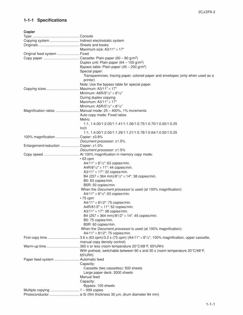
1-1-1 Specifications
CopierType ............................................... ConsoleCopying system.............................. Indirect electrostatic systemOriginals ......................................... Sheets and books
Maximum size: A3/11" × 17"Original feed system ...................... FixedCopy paper .................................... Cassette: Plain paper (60 – 80 g/m2)
Duplex unit: Plain paper (64 – 105 g/m2)Bypass table: Plain paper (45 – 200 g/m2)Special paper:
Transparencies, tracing paper, colored paper and envelopes (only when used as aprinter)
Note: Use the bypass table for special paper.Copying sizes ................................. Maximum: A3/11" × 17"
Minimum: A6R/51/2" × 81/2"During duplex copyingMaximum: A3/11" × 17"Minimum: A5R/51/2" × 81/2"
Magnification ratios ........................ Manual mode: 25 – 400%, 1% incrementsAuto copy mode: Fixed ratiosMetric
1:1, 1:4.00/1:2.00/1:1.41/1:1.06/1:0.75/1:0.70/1:0.50/1:0.25Inch
1:1, 1:4.00/1:2.00/1:1.29/1:1.21/1:0.78/1:0.64/1:0.50/1:0.25100% magnification ........................ Copier: ±0.8%
Document processor: ±1.5%Enlargement/reduction ................... Copier: ±1.0%
Document processor: ±1.5%Copy speed .................................... At 100% magnification in memory copy mode:
• 63 cpmA4/11" × 81/2": 63 copies/min.A4R/81/2" × 11": 44 copies/min.A3/11" × 17": 32 copies/min.B4 (257 × 364 mm)/81/2" × 14": 38 copies/min.B5: 63 copies/min.B5R: 50 copies/min.
When the Document processor is used (at 100% magnification):A4/11" × 81/2": 63 copies/min.
• 75 cpmA4/11" × 81/2": 75 copies/min.A4R/81/2" × 11": 52 copies/min.A3/11" × 17": 38 copies/min.B4 (257 × 364 mm)/81/2" × 14": 45 copies/min.B5: 75 copies/min.B5R: 60 copies/min.
When the Document processor is used (at 100% magnification):A4/11" × 81/2": 75 copies/min.
First copy time ................................ 3.6 s (63 cpm)/3.2 s (75 cpm) (A4/11" × 81/2", 100% magnification, upper cassette,manual copy density control)
Warm-up time ................................. 360 s or less (room temperature 20°C/68°F, 65%RH)With preheat, switchable between 90 s and 30 s (room temperature 20°C/68°F,65%RH)
Paper feed system ......................... Automatic feedCapacity:
Cassette (two cassettes): 500 sheetsLarge paper deck: 3000 sheets
Manual feedCapacity:
Bypass: 100 sheetsMultiple copying ............................. 1 – 999 copiesPhotoconductor .............................. a-Si (film thickness 30 µm, drum diameter 84 mm)
2CJ/2FA-1
1-1-2
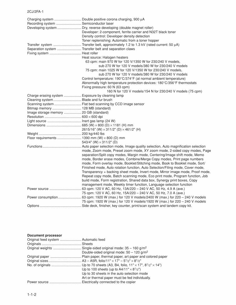
Charging system ............................ Double positive corona charging, 900 µARecording system .......................... Semiconductor laserDeveloping system ......................... Dry, reverse developing (double magnet roller)
Developer: 2-component, ferrite carrier and N32T black tonerDensity control: Developer density detectionToner replenishing: Automatic from a toner hopper
Transfer system ............................. Transfer belt, approximately 1.2 to 1.3 kV (rated current: 50 µA)Separation system ......................... Transfer belt and separation clawsFixing system ................................. Heat roller
Heat source: Halogen heaters63 cpm: main 970 W for 120 V/1350 W for 230/240 V models,
sub 270 W for 120 V models/380 W for 230/240 V models75 cpm: main 1025 W for 120 V/1350 W for 230/240 V models,
sub 270 W for 120 V models/380 W for 230/240 V modelsControl temperature: 190°C/374°F (at normal ambient temperature)Abnormally high temperature protection devices: 180°C/356°F thermostatsFixing pressure: 60 N (63 cpm)
160 N for 120 V models/154 N for 230/240 V models (75 cpm)Charge erasing system .................. Exposure by cleaning lampCleaning system............................. Blade and fur brushScanning system ............................ Flat bed scanning by CCD image sensorBitmap memory .............................. 128 MB (standard)Image storage memory .................. 20 GB (standard)Resolution ...................................... 600 × 600 dpiLight source ................................... Inert gas lamp (24 W)Dimensions .................................... 685 (W) × 800 (D) × 1181 (H) mm
2615/16" (W) × 311/2" (D) × 461/2" (H)Weight ............................................ 200 kg/440 lbsFloor requirements ......................... 1390 mm (W) × 800 (D) mm
543/4" (W) × 311/2" (D)Functions........................................ Auto paper selection mode, Image quality selection, Auto magnification selection
mode, Zoom mode, Preset zoom mode, XY zoom mode, 2-sided copy modes, Pageseparation/Split copy modes, Margin mode, Centering/Image shift mode, Memomode, Border erase modes, Combine/Merge Copy modes, Print page numbersmode, Form overlay mode, Booklet/Stitching mode, Book to Booklet mode, Sort/Finished mode, Auto rotation function, Auto Selection/Filing mode, Cover mode,Transparency + backing sheet mode, Invert mode, Mirror image mode, Proof mode,Repeat copy mode, Batch scanning mode, Eco print mode, Program function, Jobbuild mode, Form registration, Shared data box, Synergy print boxes, Copymanagement mode, Weekly timer function, Language selection function
Power source ................................. 63 cpm: 120 V AC, 60 Hz, 13A/220 – 240 V AC, 50 Hz, 4.9 A (ave.)75 cpm: 120 V AC, 60 Hz, 15A/220 – 240 V AC, 50 Hz, 7.0 A (ave.)
Power consumption........................ 63 cpm: 1920 W (max.) for 120 V models/2400 W (max.) for 220 – 240 V models75 cpm: 1920 W (max.) for 120 V models/1920 W (max.) for 220 – 240 V models
Options ........................................... Side deck, finisher, key counter, print/scan system and tandem copy kit.
Document processorOriginal feed system ...................... Automatic feedOriginals ......................................... SheetsOriginal weights ............................. Single-sided original mode: 35 – 160 g/m2
Double-sided original mode: 50 – 120 g/m2
Original paper ................................ Plain paper, thermal paper, art paper and colored paperOriginal sizes.................................. A3 – A5R, folio/11" × 17" – 51/2" × 81/2"No. of originals ............................... Up to 70 sheets (A3, B4, folio, 11" × 17", 81/2" × 14")
Up to 100 sheets (up to A4/11" × 81/2")Up to 30 sheets in the auto selection modeArt or thermal paper must be fed individually.
Power source ................................. Electrically connected to the copier
2CJ/2FA-2
1-1-3
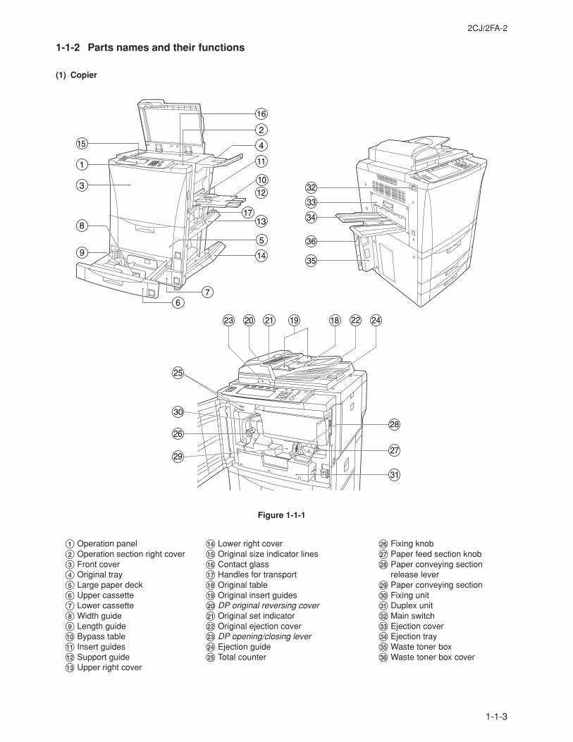
1-1-2 Parts names and their functions
(1) Copier
Figure 1-1-1
1 Operation panel2 Operation section right cover3 Front cover4 Original tray5 Large paper deck6 Upper cassette7 Lower cassette8 Width guide9 Length guide0 Bypass table! Insert guides@ Support guide# Upper right cover
$ Lower right cover% Original size indicator lines^ Contact glass& Handles for transport* Original table( Original insert guides) DP original reversing cover⁄ Original set indicator¤ Original ejection cover‹ DP opening/closing lever› Ejection guidefi Total counter
fl Fixing knob‡ Paper feed section knob— Paper conveying section
release lever· Paper conveying section‚ Fixing unitŒ Duplex unit„ Main switch´ Ejection cover‰ Ejection trayˇ Waste toner boxÁ Waste toner box cover
2CJ/2FA
1-1-4
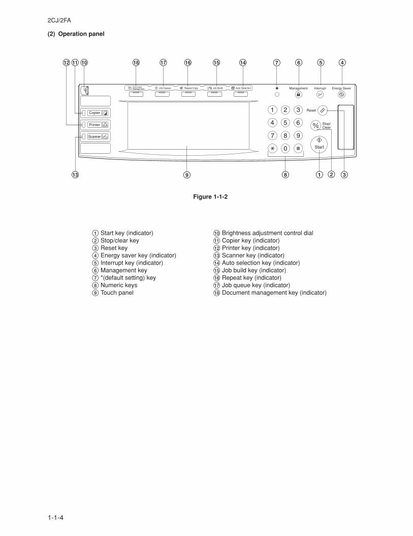
(2) Operation panel
1 Start key (indicator)2 Stop/clear key3 Reset key4 Energy saver key (indicator)5 Interrupt key (indicator)6 Management key7 *(default setting) key8 Numeric keys9 Touch panel
0 Brightness adjustment control dial! Copier key (indicator)@ Printer key (indicator)# Scanner key (indicator)$ Auto selection key (indicator)% Job build key (indicator)^ Repeat key (indicator)& Job queue key (indicator)* Document management key (indicator)
Figure 1-1-2
7 6 5 4
9 18 32
$%^&*0@!
#
2CJ/2FA-2
1-1-5
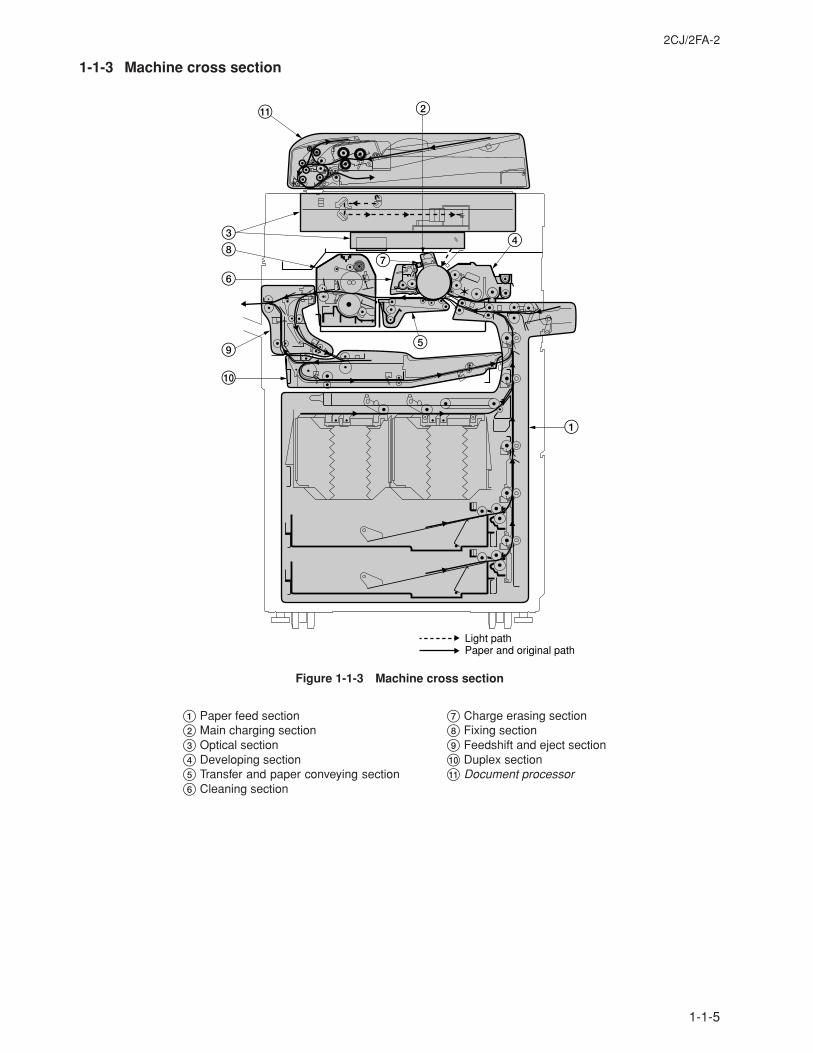
1-1-3 Machine cross section
Figure 1-1-3 Machine cross section
Light pathPaper and original path
1
2
38
6
9
0
!
5
4
7
1 Paper feed section2 Main charging section3 Optical section4 Developing section5 Transfer and paper conveying section6 Cleaning section
7 Charge erasing section8 Fixing section9 Feedshift and eject section0 Duplex section! Document processor
2CJ/2FA
1-1-6
6
6 5
4
1
23
6
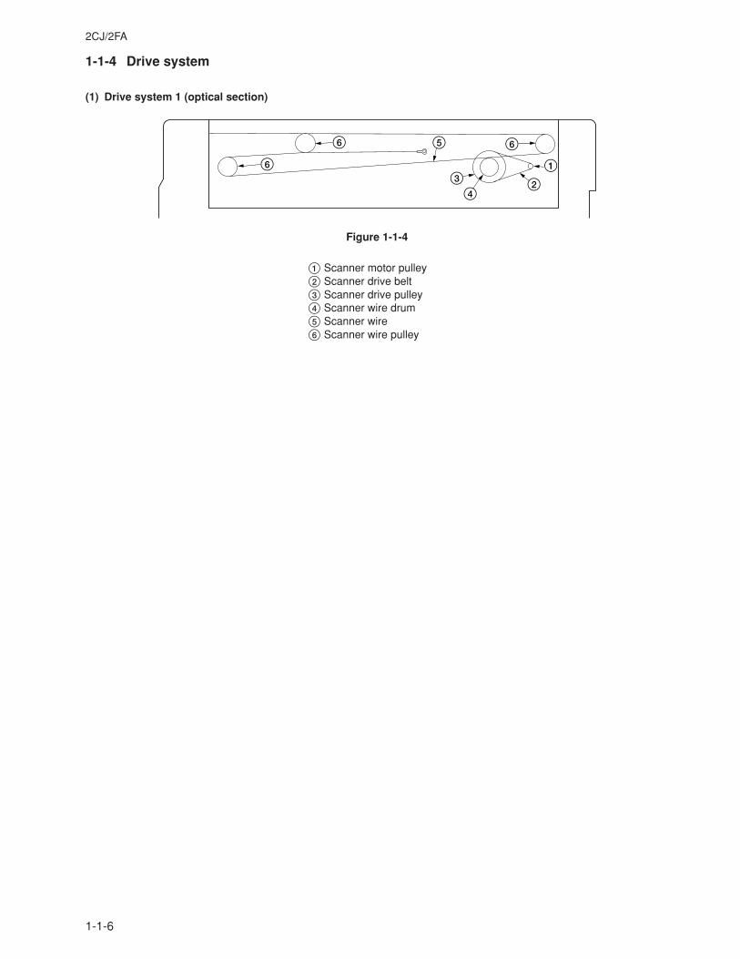
1-1-4 Drive system
(1) Drive system 1 (optical section)
Figure 1-1-4
1 Scanner motor pulley2 Scanner drive belt3 Scanner drive pulley4 Scanner wire drum5 Scanner wire6 Scanner wire pulley
2CJ/2FA
1-1-7
1fifl‡
›
°‚
Œ
·
¤
‹
„ ‰
´
ˇ
2
3
45
67
Á
8
9
0!@
#
$%
^
&
*(
⁄)
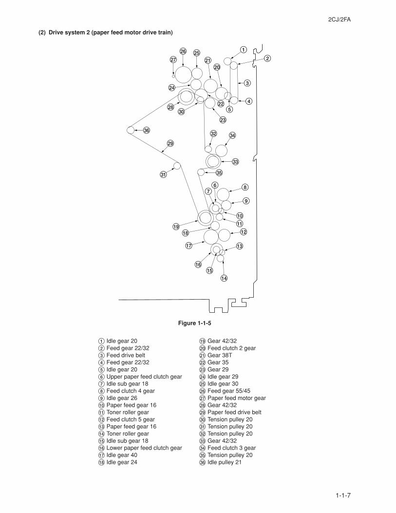
(2) Drive system 2 (paper feed motor drive train)
Figure 1-1-5
1 Idle gear 202 Feed gear 22/323 Feed drive belt4 Feed gear 22/325 Idle gear 206 Upper paper feed clutch gear7 Idle sub gear 188 Feed clutch 4 gear9 Idle gear 260 Paper feed gear 16! Toner roller gear@ Feed clutch 5 gear# Paper feed gear 16$ Toner roller gear% Idle sub gear 18^ Lower paper feed clutch gear& Idle gear 40* Idle gear 24
( Gear 42/32) Feed clutch 2 gear⁄ Gear 38T¤ Gear 35‹ Gear 29› Idle gear 29fi Idle gear 30fl Feed gear 55/45‡ Paper feed motor gear— Gear 42/32· Paper feed drive belt‚ Tension pulley 20Œ Tension pulley 20„ Tension pulley 20´ Gear 42/32‰ Feed clutch 3 gearˇ Tension pulley 20Á Idle pulley 21
2CJ/2FA
1-1-8
123
4
5
678
90!
@
# $%
^
&
*()⁄
¤
‹›
fifl
‡
°
·
‚
Œ
„
123
4
5
0
6
789!
@
#
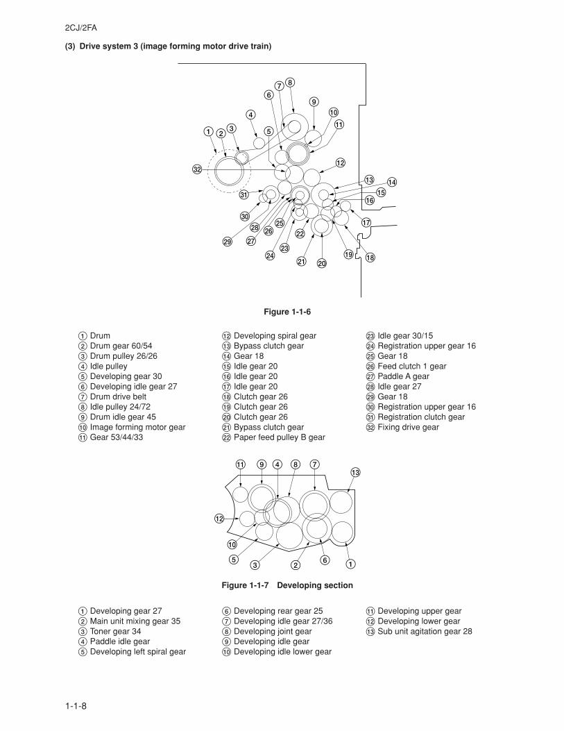
(3) Drive system 3 (image forming motor drive train)
Figure 1-1-6
1 Drum2 Drum gear 60/543 Drum pulley 26/264 Idle pulley5 Developing gear 306 Developing idle gear 277 Drum drive belt8 Idle pulley 24/729 Drum idle gear 450 Image forming motor gear! Gear 53/44/33
@ Developing spiral gear# Bypass clutch gear$ Gear 18% Idle gear 20^ Idle gear 20& Idle gear 20* Clutch gear 26( Clutch gear 26) Clutch gear 26⁄ Bypass clutch gear¤ Paper feed pulley B gear
‹ Idle gear 30/15› Registration upper gear 16fi Gear 18fl Feed clutch 1 gear‡ Paddle A gear— Idle gear 27· Gear 18‚ Registration upper gear 16Œ Registration clutch gear„ Fixing drive gear
Figure 1-1-7 Developing section
1 Developing gear 272 Main unit mixing gear 353 Toner gear 344 Paddle idle gear5 Developing left spiral gear
6 Developing rear gear 257 Developing idle gear 27/368 Developing joint gear9 Developing idle gear0 Developing idle lower gear
! Developing upper gear@ Developing lower gear# Sub unit agitation gear 28
2CJ/2FA
1-1-9
2Î 1
345
678
0@#
$
%
)
¤
⁄
‹›
fl‡
°·
‚˘
¿¡™
£¢
„´‰
ˇÁ¨
¸
◊
ı
¯Â
˜
˛
Ç
Ú
Ò
ˆ
Ô
Ó Ø”˝Ï
Å
Í
Œ
9
!
(
fi
^
&
*
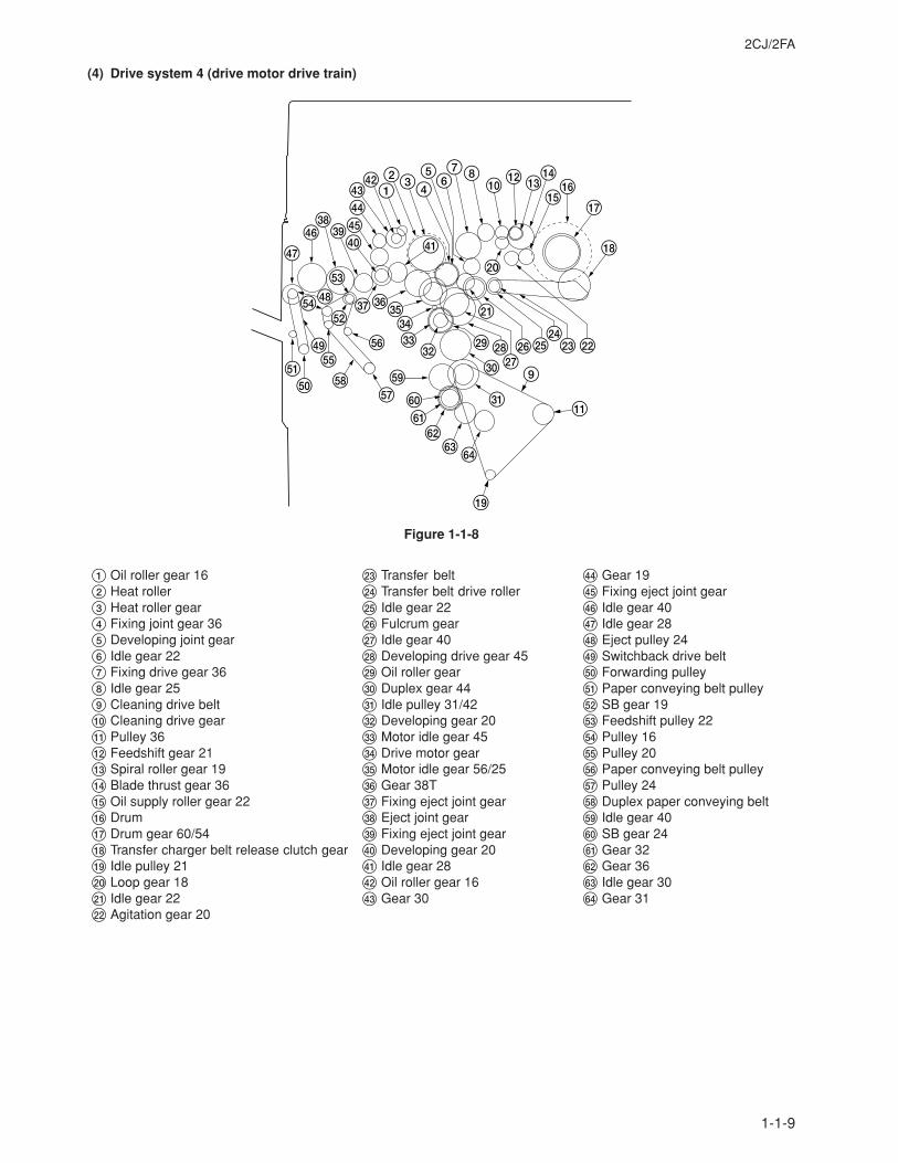
(4) Drive system 4 (drive motor drive train)
Figure 1-1-8
1 Oil roller gear 162 Heat roller3 Heat roller gear4 Fixing joint gear 365 Developing joint gear6 Idle gear 227 Fixing drive gear 368 Idle gear 259 Cleaning drive belt0 Cleaning drive gear! Pulley 36@ Feedshift gear 21# Spiral roller gear 19$ Blade thrust gear 36% Oil supply roller gear 22^ Drum& Drum gear 60/54* Transfer charger belt release clutch gear( Idle pulley 21) Loop gear 18⁄ Idle gear 22¤ Agitation gear 20
‹ Transfer belt› Transfer belt drive rollerfi Idle gear 22fl Fulcrum gear‡ Idle gear 40— Developing drive gear 45· Oil roller gear‚ Duplex gear 44Œ Idle pulley 31/42„ Developing gear 20´ Motor idle gear 45‰ Drive motor gearˇ Motor idle gear 56/25Á Gear 38T¨ Fixing eject joint gearˆ Eject joint gearØ Fixing eject joint gear” Developing gear 20Å Idle gear 28Í Oil roller gear 16Î Gear 30
Ï Gear 19˝ Fixing eject joint gearÓ Idle gear 40Ô Idle gear 28Æ Eject pulley 24Ò Switchback drive beltÚ Forwarding pulley¸ Paper conveying belt pulley˛ SB gear 19Ç Feedshift pulley 22– Pulley 16ı Pulley 20˜ Paper conveying belt pulley Pulley 24¯ Duplex paper conveying belt˘ Idle gear 40¿ SB gear 24¡ Gear 32™ Gear 36£ Idle gear 30¢ Gear 31
2CJ/2FA
1-1-10
3
7
8
90
¤*(
!@#$%)⁄
6 6
fi
fl
32
4
‹
1
^&
5
›
1
2
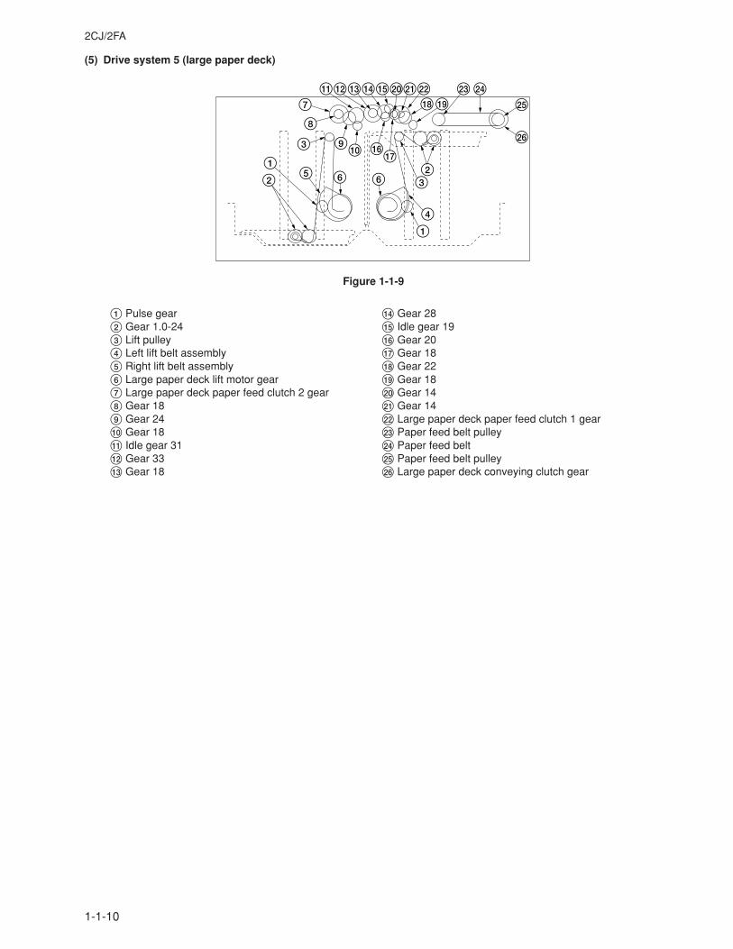
(5) Drive system 5 (large paper deck)
Figure 1-1-9
1 Pulse gear2 Gear 1.0-243 Lift pulley4 Left lift belt assembly5 Right lift belt assembly6 Large paper deck lift motor gear7 Large paper deck paper feed clutch 2 gear8 Gear 189 Gear 240 Gear 18! Idle gear 31@ Gear 33# Gear 18
$ Gear 28% Idle gear 19^ Gear 20& Gear 18* Gear 22( Gear 18) Gear 14⁄ Gear 14¤ Large paper deck paper feed clutch 1 gear‹ Paper feed belt pulley› Paper feed beltfi Paper feed belt pulleyfl Large paper deck conveying clutch gear
2CJ/2FA
1-1-11
65
4
7
2^
&
87 %$
90
31
!@
#
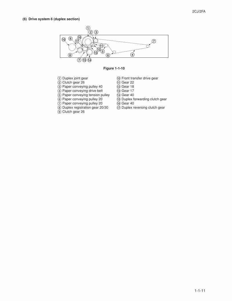
(6) Drive system 6 (duplex section)
Figure 1-1-10
1 Duplex joint gear2 Clutch gear 263 Paper conveying pulley 404 Paper conveying drive belt5 Paper conveying tension pulley6 Paper conveying pulley 207 Paper conveying pulley 208 Duplex registration gear 20/309 Clutch gear 26
0 Front transfer drive gear! Gear 22@ Gear 18# Gear 17$ Gear 40% Duplex forwarding clutch gear^ Gear 40& Duplex reversing clutch gear
2CJ/2FA-2
1-1-12
6
9 5
4 3
!@
0
*
%&
$287
1
^
#
As viewed from machine rear
As viewed from machine front
4!
7
8
65
91
0 3
2
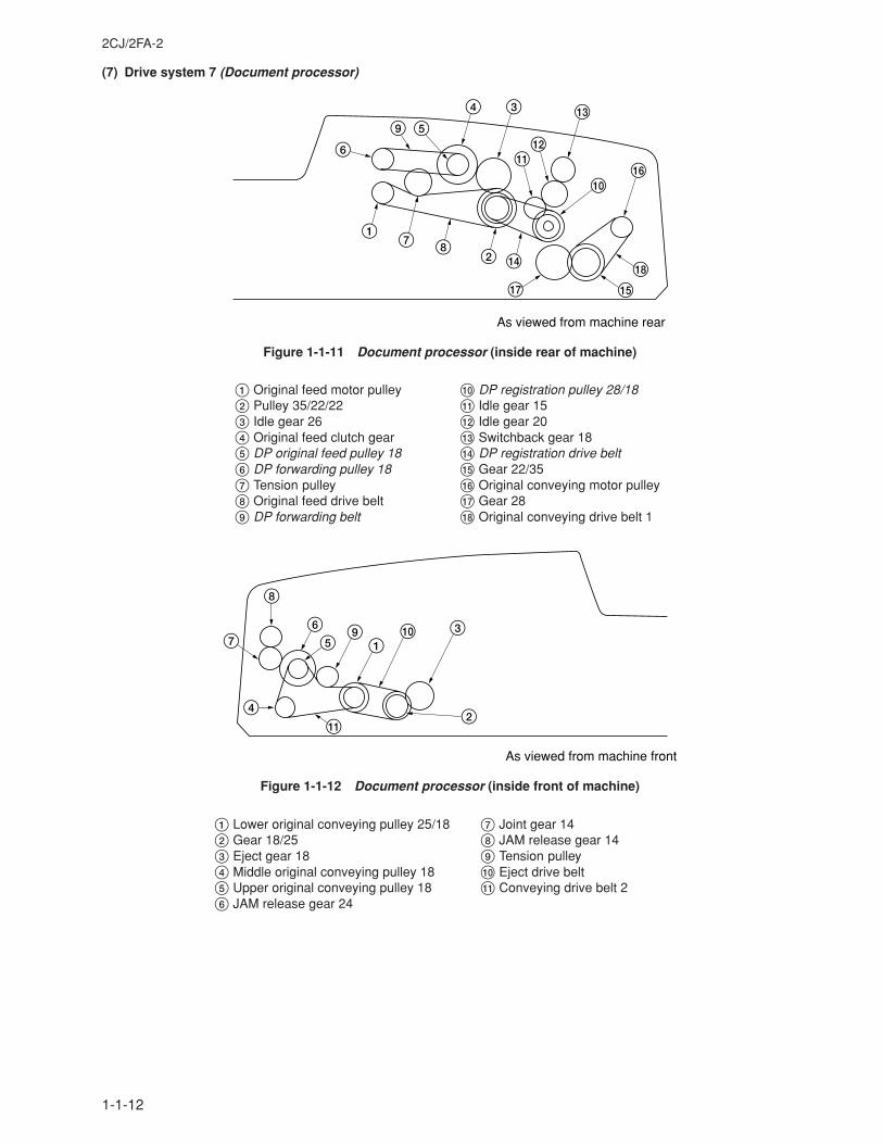
(7) Drive system 7 (Document processor)
Figure 1-1-11 Document processor (inside rear of machine)
Figure 1-1-12 Document processor (inside front of machine)
1 Original feed motor pulley2 Pulley 35/22/223 Idle gear 264 Original feed clutch gear5 DP original feed pulley 186 DP forwarding pulley 187 Tension pulley8 Original feed drive belt9 DP forwarding belt
0 DP registration pulley 28/18! Idle gear 15@ Idle gear 20# Switchback gear 18$ DP registration drive belt% Gear 22/35^ Original conveying motor pulley& Gear 28* Original conveying drive belt 1
1 Lower original conveying pulley 25/182 Gear 18/253 Eject gear 184 Middle original conveying pulley 185 Upper original conveying pulley 186 JAM release gear 24
7 Joint gear 148 JAM release gear 149 Tension pulley0 Eject drive belt! Conveying drive belt 2
2CJ/2FA-1
1-2-1
1-2-1 DrumNote the following when handling or storing the drum.• When removing the image formation unit, never expose the drum surface to strong direct light.• Keep the drum at an ambient temperature between –20°C/–4°F and 40°C/104°F and at a relative humidity not higher
than 90% RH. Avoid abrupt changes in temperature and humidity.• Avoid exposure to any substance which is harmful to or may affect the quality of the drum.• Do not touch the drum surface with any object. Should it be touched by hands or stained with oil, clean it.
1-2-2 Developer and tonerStore the developer and toner in a cool, dark place. Avoid direct light and high humidity.
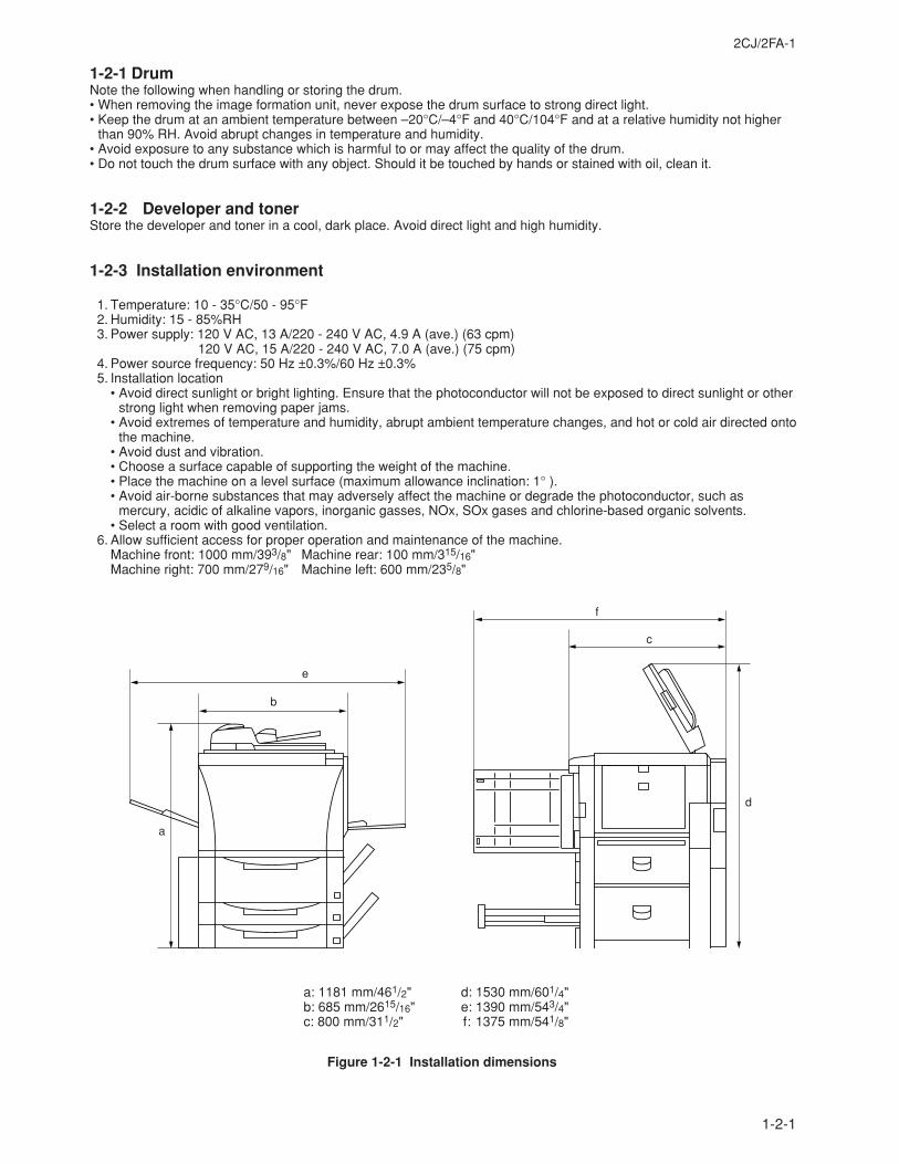
1-2-3 Installation environment
1. Temperature: 10 - 35°C/50 - 95°F 2. Humidity: 15 - 85%RH 3. Power supply: 120 V AC, 13 A/220 - 240 V AC, 4.9 A (ave.) (63 cpm)
120 V AC, 15 A/220 - 240 V AC, 7.0 A (ave.) (75 cpm) 4. Power source frequency: 50 Hz ±0.3%/60 Hz ±0.3% 5. Installation location
• Avoid direct sunlight or bright lighting. Ensure that the photoconductor will not be exposed to direct sunlight or otherstrong light when removing paper jams.
• Avoid extremes of temperature and humidity, abrupt ambient temperature changes, and hot or cold air directed ontothe machine.
• Avoid dust and vibration.• Choose a surface capable of supporting the weight of the machine.• Place the machine on a level surface (maximum allowance inclination: 1° ).• Avoid air-borne substances that may adversely affect the machine or degrade the photoconductor, such as
mercury, acidic of alkaline vapors, inorganic gasses, NOx, SOx gases and chlorine-based organic solvents.• Select a room with good ventilation.
6. Allow sufficient access for proper operation and maintenance of the machine.Machine front: 1000 mm/393/8" Machine rear: 100 mm/315/16"Machine right: 700 mm/279/16" Machine left: 600 mm/235/8"
Figure 1-2-1 Installation dimensions
a: 1181 mm/461/2"b: 685 mm/2615/16"c: 800 mm/311/2"
d: 1530 mm/601/4"e: 1390 mm/543/4"f: 1375 mm/541/8"
a
b
e
c
d
f
1-3-1
2CJ/2FA-1
1-3-1 Unpacking and installation
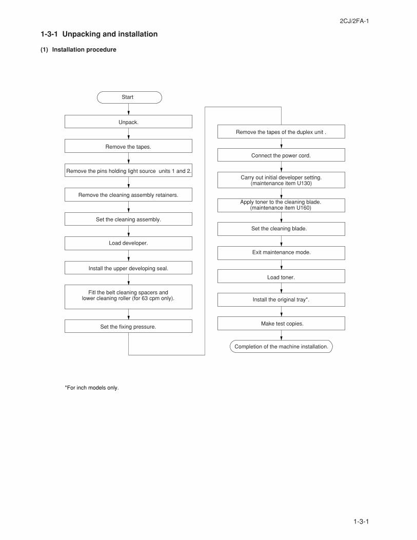
(1) Installation procedure
Unpack.
Remove the tapes.
Make test copies.
Install the original tray*.
Remove the pins holding light source units 1 and 2.
Load developer.
Connect the power cord.
Remove the tapes of the duplex unit .
Load toner.
Fitl the belt cleaning spacers and lower cleaning roller (for 63 cpm only).
Set the fixing pressure.
Exit maintenance mode.
Apply toner to the cleaning blade.(maintenance item U160)
Set the cleaning blade.
Start
Set the cleaning assembly.
Install the upper developing seal.
Carry out initial developer setting. (maintenance item U130)
Remove the cleaning assembly retainers.
Completion of the machine installation.
*For inch models only.
1-3-2
2CJ/2FA
6
´
´
›
fi
8
¤9
)‰
Î
‹
#
⁄
ˇÏ
4
Ó
4Ï
Ïfl
Í
‡„
‚ Œ
%
%
˝
%
%
$(
&
^*
5
7
1
233
ÅÔ
ˆÁ
ب
%
°·
@
!
0
∏
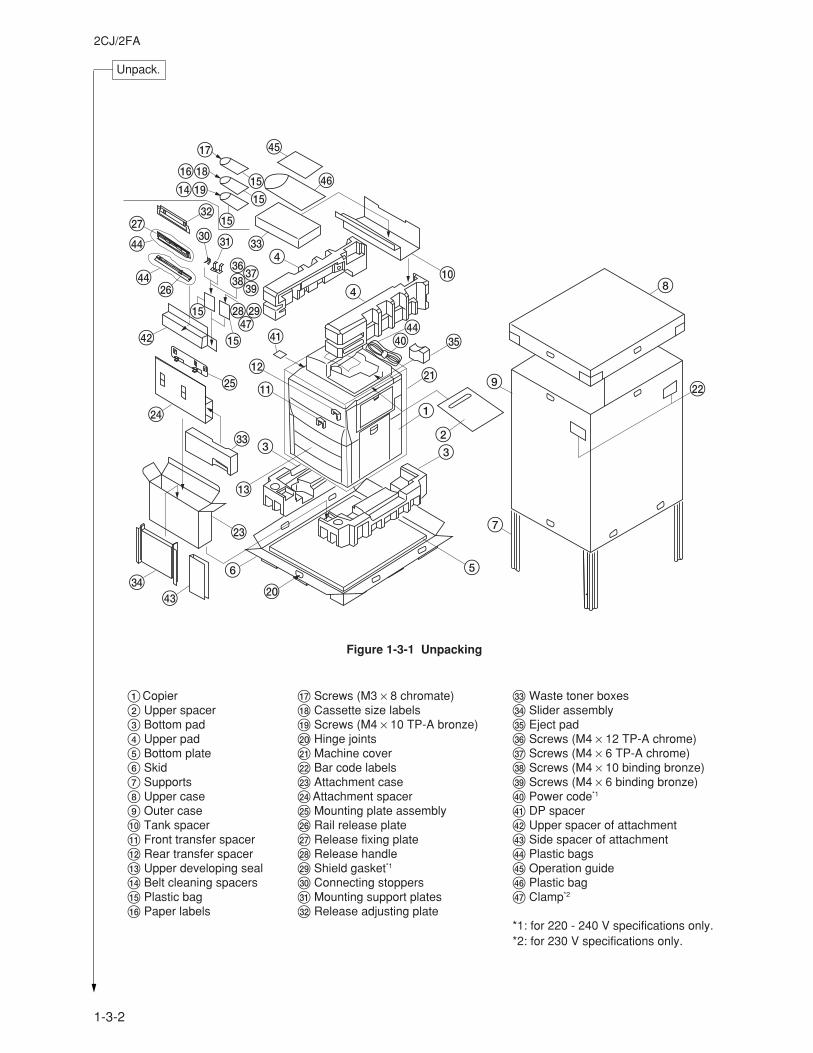
Figure 1-3-1 Unpacking
Unpack.
1Copier2 Upper spacer3 Bottom pad4 Upper pad5 Bottom plate6 Skid7 Supports8 Upper case9 Outer case0 Tank spacer! Front transfer spacer@ Rear transfer spacer# Upper developing seal$ Belt cleaning spacers% Plastic bag^ Paper labels
& Screws (M3 × 8 chromate)* Cassette size labels( Screws (M4 × 10 TP-A bronze)) Hinge joints⁄ Machine cover¤ Bar code labels‹ Attachment case›Attachment spacerfi Mounting plate assemblyfl Rail release plate‡ Release fixing plate° Release handle· Shield gasket*1
‚ Connecting stoppersŒ Mounting support plates„ Release adjusting plate
´ Waste toner boxes‰ Slider assemblyˇ Eject padÁ Screws (M4 × 12 TP-A chrome)¨ Screws (M4 × 6 TP-A chrome)ˆ Screws (M4 × 10 binding bronze)Ø Screws (M4 × 6 binding bronze)∏ Power code*1
Å DP spacerÍ Upper spacer of attachmentÎ Side spacer of attachmentÏ Plastic bags˝ Operation guideÓ Plastic bagÔ Clamp*2
*1: for 220 - 240 V specifications only.*2: for 230 V specifications only.
1-3-3
2CJ/2FA-2
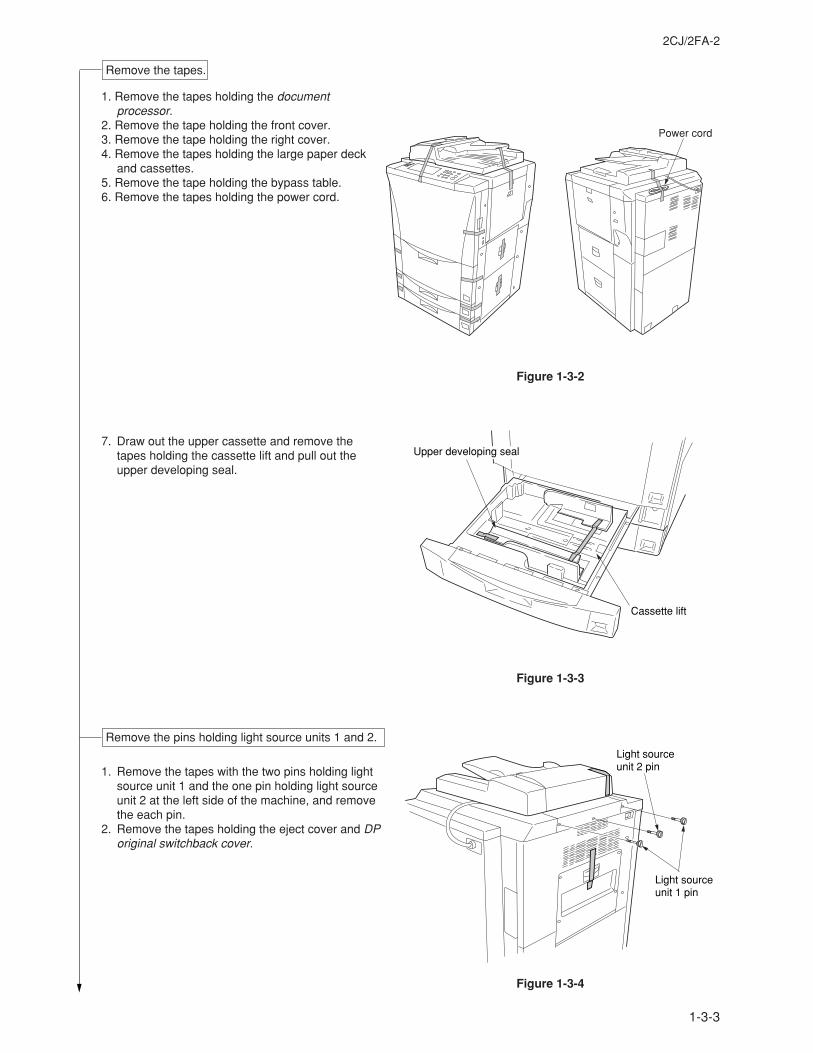
1. Remove the tapes holding the documentprocessor.
2. Remove the tape holding the front cover. 3. Remove the tape holding the right cover. 4. Remove the tapes holding the large paper deck
and cassettes. 5. Remove the tape holding the bypass table. 6. Remove the tapes holding the power cord.
7. Draw out the upper cassette and remove thetapes holding the cassette lift and pull out theupper developing seal.
1. Remove the tapes with the two pins holding lightsource unit 1 and the one pin holding light sourceunit 2 at the left side of the machine, and removethe each pin.
2. Remove the tapes holding the eject cover and DPoriginal switchback cover.
Remove the tapes.
Figure 1-3-2
Power cord
Upper developing seal
Cassette lift
Figure 1-3-3
Remove the pins holding light source units 1 and 2.Light sourceunit 2 pin
Light sourceunit 1 pin
Figure 1-3-4
1-3-4
2CJ/2FA
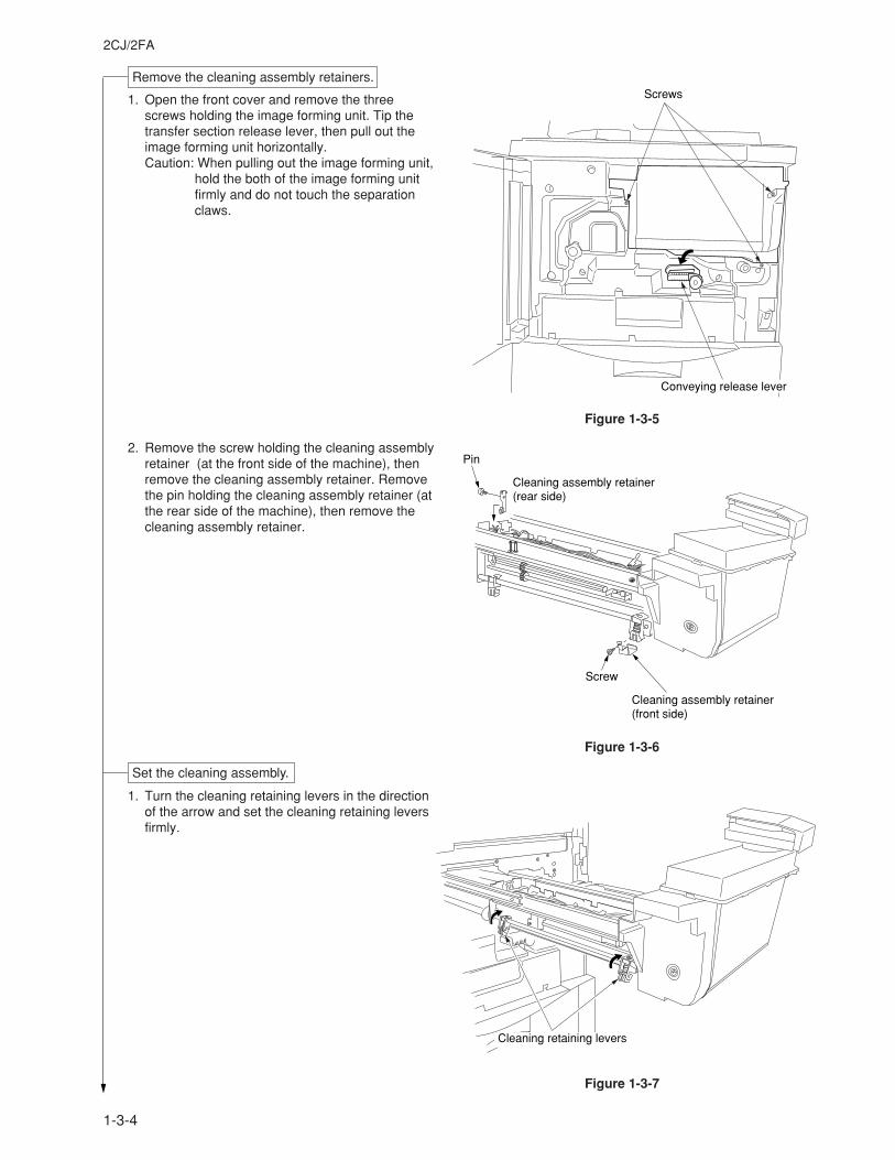
Figure 1-3-5
1. Open the front cover and remove the threescrews holding the image forming unit. Tip thetransfer section release lever, then pull out theimage forming unit horizontally.Caution: When pulling out the image forming unit,
hold the both of the image forming unitfirmly and do not touch the separationclaws.
2. Remove the screw holding the cleaning assemblyretainer (at the front side of the machine), thenremove the cleaning assembly retainer. Removethe pin holding the cleaning assembly retainer (atthe rear side of the machine), then remove thecleaning assembly retainer.
1. Turn the cleaning retaining levers in the directionof the arrow and set the cleaning retaining leversfirmly.
Screws
Conveying release lever
Pin
Cleaning assembly retainer(rear side)
Cleaning assembly retainer(front side)
Screw
Figure 1-3-6
Remove the cleaning assembly retainers.
Figure 1-3-7
Cleaning retaining levers
Set the cleaning assembly.
1-3-5
2CJ/2FA
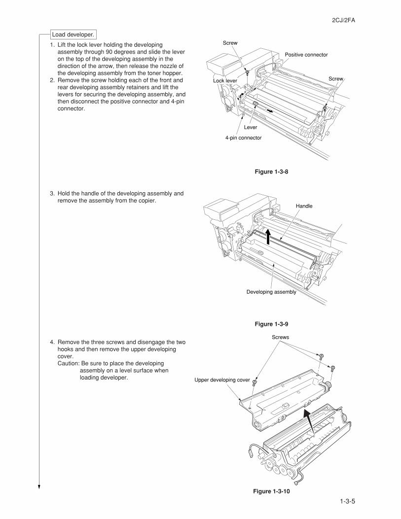
Load developer.
1. Lift the lock lever holding the developingassembly through 90 degrees and slide the leveron the top of the developing assembly in thedirection of the arrow, then release the nozzle ofthe developing assembly from the toner hopper.
2. Remove the screw holding each of the front andrear developing assembly retainers and lift thelevers for securing the developing assembly, andthen disconnect the positive connector and 4-pinconnector.
3. Hold the handle of the developing assembly andremove the assembly from the copier.
4. Remove the three screws and disengage the twohooks and then remove the upper developingcover.Caution: Be sure to place the developing
assembly on a level surface whenloading developer.
Figure 1-3-8
Screw
Lever
4-pin connector
Lock lever
Positive connector
Screw
Figure 1-3-9
Handle
Developing assembly
Figure 1-3-10
Screws
Upper developing cover
1-3-6
2CJ/2FA
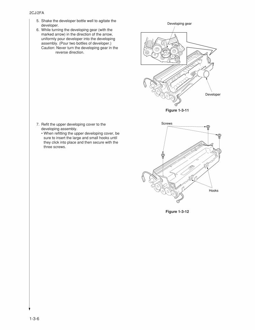
5. Shake the developer bottle well to agitate thedeveloper.
6. While turning the developing gear (with themarked arrow) in the direction of the arrow,uniformly pour developer into the developingassembly. (Pour two bottles of developer.)Caution: Never turn the developing gear in the
reverse direction.
7. Refit the upper developing cover to thedeveloping assembly.• When refitting the upper developing cover, be
sure to insert the large and small hooks untilthey click into place and then secure with thethree screws.
Developing gear
Developer
Figure 1-3-11
Screws
Hooks
Figure 1-3-12
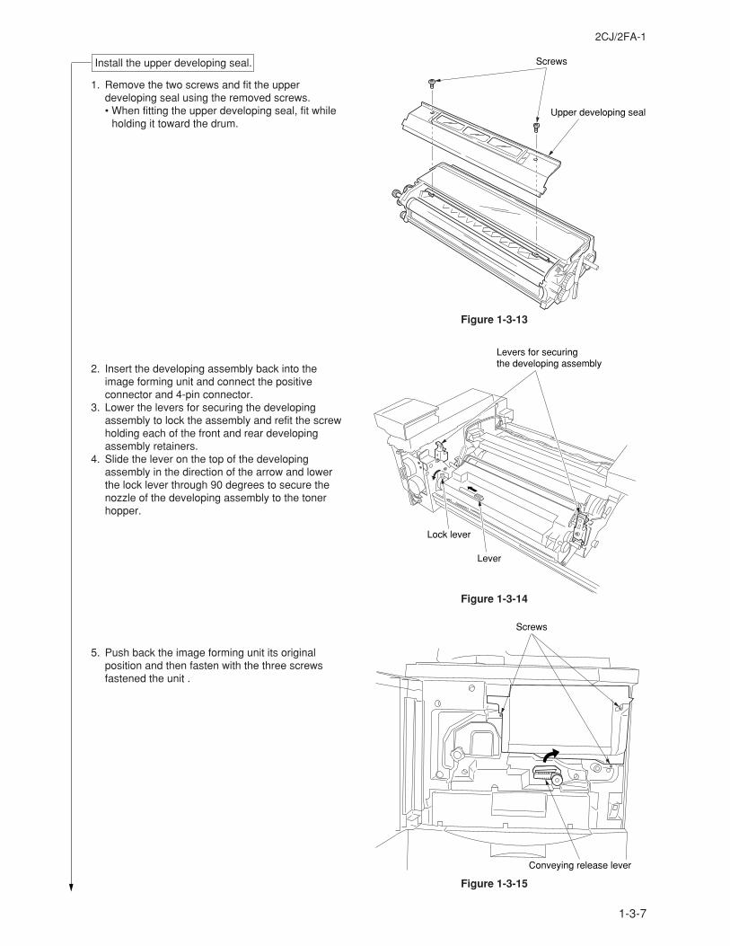
1-3-7
2CJ/2FA-1
Install the upper developing seal. Screws
Upper developing seal
Figure 1-3-13
1. Remove the two screws and fit the upperdeveloping seal using the removed screws.• When fitting the upper developing seal, fit while
holding it toward the drum.
2. Insert the developing assembly back into theimage forming unit and connect the positiveconnector and 4-pin connector.
3. Lower the levers for securing the developingassembly to lock the assembly and refit the screwholding each of the front and rear developingassembly retainers.
4. Slide the lever on the top of the developingassembly in the direction of the arrow and lowerthe lock lever through 90 degrees to secure thenozzle of the developing assembly to the tonerhopper.
5. Push back the image forming unit its originalposition and then fasten with the three screwsfastened the unit .
Levers for securing the developing assembly
Lock lever
Lever
Figure 1-3-14
Screws
Conveying release lever
Figure 1-3-15
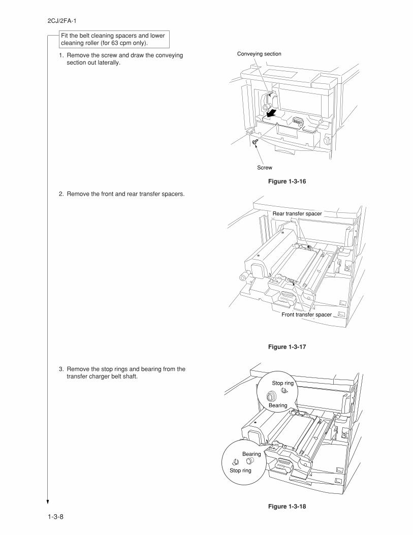
1-3-8
2CJ/2FA-1
Fit the belt cleaning spacers and lowercleaning roller (for 63 cpm only).
1. Remove the screw and draw the conveyingsection out laterally.
2. Remove the front and rear transfer spacers.
3. Remove the stop rings and bearing from thetransfer charger belt shaft.
Figure 1-3-16
Conveying section
Screw
Figure 1-3-17
Front transfer spacer
Rear transfer spacer
Figure 1-3-18
Stop ring
Stop ring
Bearing
Bearing
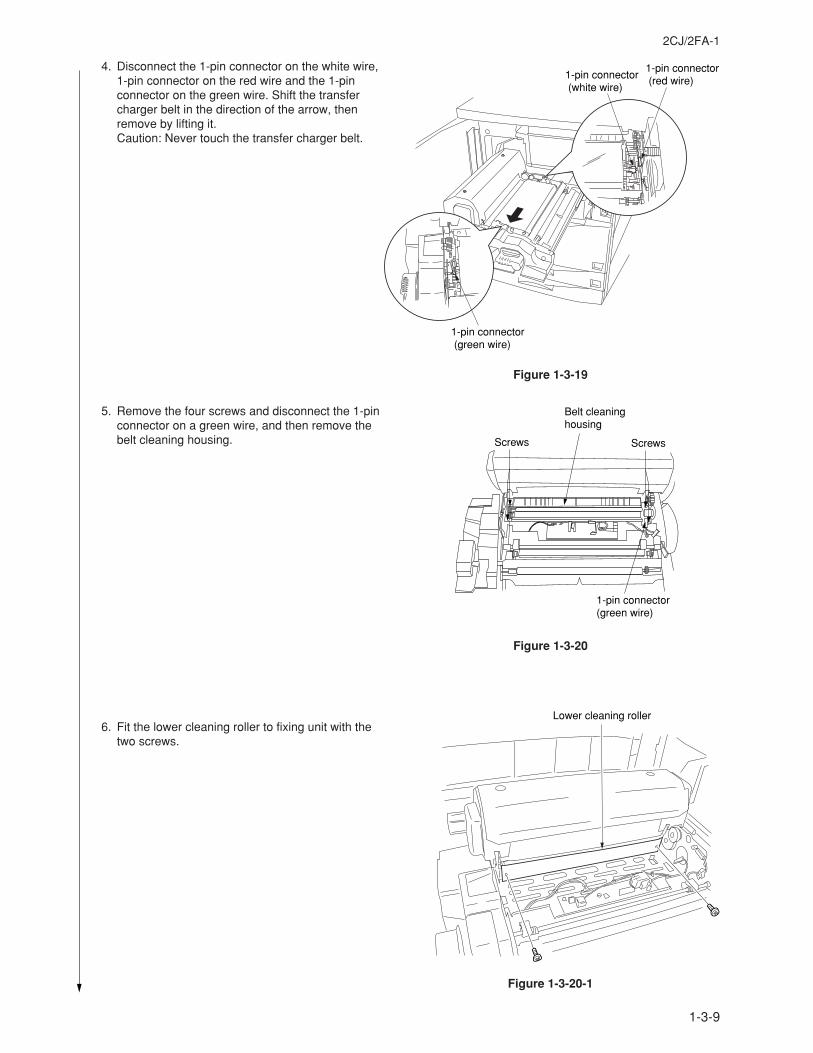
1-3-9
2CJ/2FA-1
Figure 1-3-19
4. Disconnect the 1-pin connector on the white wire,1-pin connector on the red wire and the 1-pinconnector on the green wire. Shift the transfercharger belt in the direction of the arrow, thenremove by lifting it.Caution: Never touch the transfer charger belt.
5. Remove the four screws and disconnect the 1-pinconnector on a green wire, and then remove thebelt cleaning housing.
6. Fit the lower cleaning roller to fixing unit with thetwo screws.
1-pin connector (white wire)
1-pin connector (red wire)
1-pin connector (green wire)
Figure 1-3-20
Screws Screws
Belt cleaninghousing
1-pin connector(green wire)
Figure 1-3-20-1
Lower cleaning roller
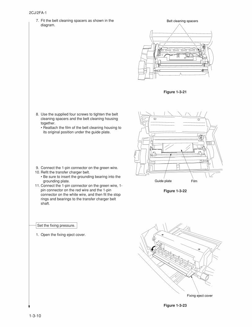
1-3-10
2CJ/2FA-1
Figure 1-3-22
7. Fit the belt cleaning spacers as shown in thediagram.
8. Use the supplied four screws to tighten the beltcleaning spacers and the belt cleaning housingtogether.• Reattach the film of the belt cleaning housing to
its original position under the guide plate.
9. Connect the 1-pin connector on the green wire.10. Refit the transfer charger belt.
• Be sure to insert the grounding bearing into thegrounding plate.
11. Connect the 1-pin connector on the green wire, 1-pin connector on the red wire and the 1-pinconnector on the white wire, and then fit the stoprings and bearings to the transfer charger beltshaft.
1. Open the fixing eject cover.
Set the fixing pressure.
Fixing eject cover
Figure 1-3-23
Guide plate Film
Figure 1-3-21
Belt cleaning spacers
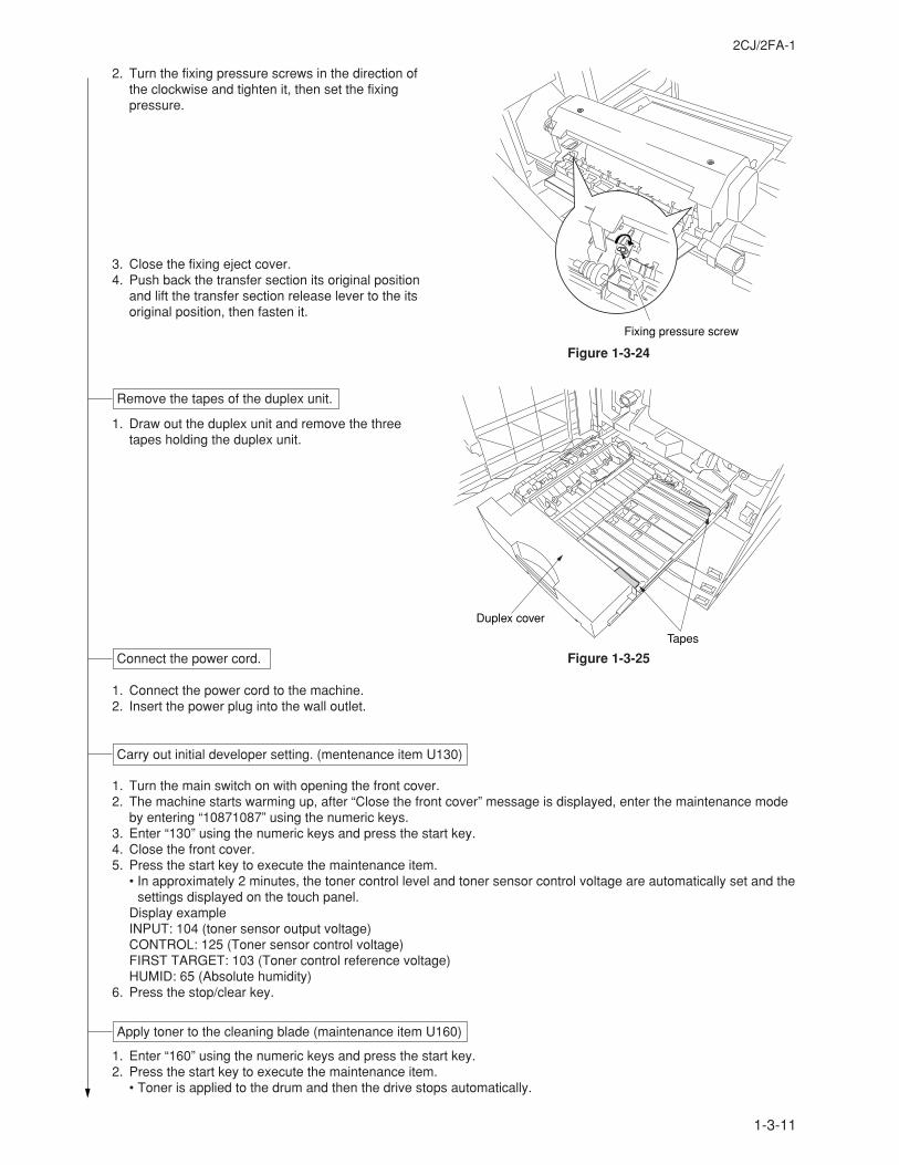
1-3-11
2CJ/2FA-1
Carry out initial developer setting. (mentenance item U130)
1. Connect the power cord to the machine. 2. Insert the power plug into the wall outlet.
1. Turn the main switch on with opening the front cover. 2. The machine starts warming up, after “Close the front cover” message is displayed, enter the maintenance mode
by entering “10871087” using the numeric keys. 3. Enter “130” using the numeric keys and press the start key. 4. Close the front cover. 5. Press the start key to execute the maintenance item.
• In approximately 2 minutes, the toner control level and toner sensor control voltage are automatically set and thesettings displayed on the touch panel.
Display exampleINPUT: 104 (toner sensor output voltage)CONTROL: 125 (Toner sensor control voltage)FIRST TARGET: 103 (Toner control reference voltage)HUMID: 65 (Absolute humidity)
6. Press the stop/clear key.
1. Enter “160” using the numeric keys and press the start key. 2. Press the start key to execute the maintenance item.
• Toner is applied to the drum and then the drive stops automatically.
Connect the power cord.
Apply toner to the cleaning blade (maintenance item U160)
Figure 1-3-25
Tapes
Duplex cover
Remove the tapes of the duplex unit.
1. Draw out the duplex unit and remove the threetapes holding the duplex unit.
Figure 1-3-24
Fixing pressure screw
2. Turn the fixing pressure screws in the direction ofthe clockwise and tighten it, then set the fixingpressure.
3. Close the fixing eject cover. 4. Push back the transfer section its original position
and lift the transfer section release lever to the itsoriginal position, then fasten it.
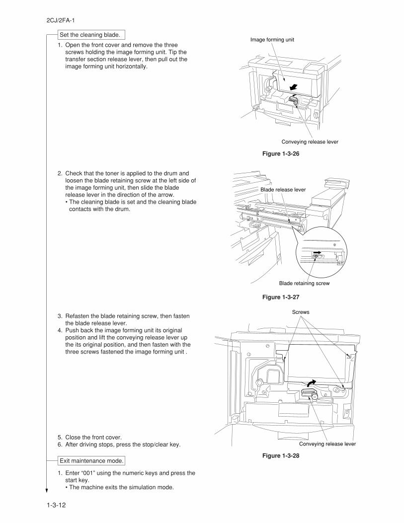
1-3-12
2CJ/2FA-1
Set the cleaning blade.
1. Open the front cover and remove the threescrews holding the image forming unit. Tip thetransfer section release lever, then pull out theimage forming unit horizontally.
2. Check that the toner is applied to the drum andloosen the blade retaining screw at the left side ofthe image forming unit, then slide the bladerelease lever in the direction of the arrow.• The cleaning blade is set and the cleaning blade
contacts with the drum.
3. Refasten the blade retaining screw, then fastenthe blade release lever.
4. Push back the image forming unit its originalposition and lift the conveying release lever upthe its original position, and then fasten with thethree screws fastened the image forming unit .
5. Close the front cover. 6. After driving stops, press the stop/clear key.
1. Enter “001” using the numeric keys and press thestart key.• The machine exits the simulation mode.
Figure 1-3-26
Conveying release lever
Image forming unit
Blade release lever
Blade retaining screw
Figure 1-3-27
Screws
Conveying release lever
Figure 1-3-28Exit maintenance mode.
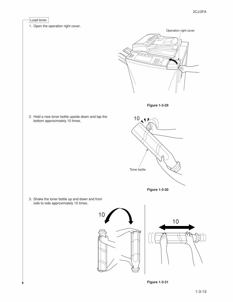
1-3-13
2CJ/2FA
Load toner.
1. Open the operation right cover.
2. Hold a new toner bottle upside down and tap thebottom approximately 10 times.
3. Shake the toner bottle up and down and fromside to side approximately 10 times.
Figure 1-3-29
Figure 1-3-30
Figure 1-3-31
Operation right cover
Toner bottle
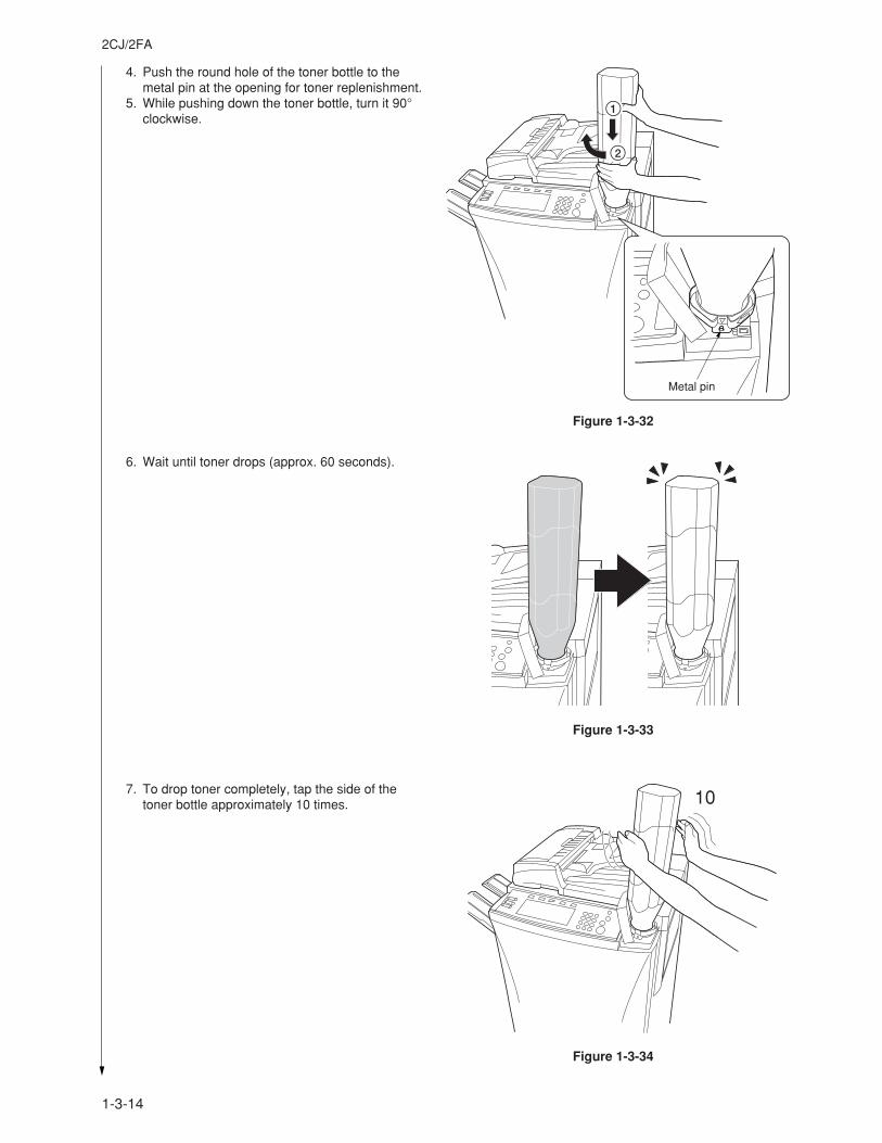
1-3-14
2CJ/2FA
4. Push the round hole of the toner bottle to themetal pin at the opening for toner replenishment.
5. While pushing down the toner bottle, turn it 90°clockwise.
6. Wait until toner drops (approx. 60 seconds).
7. To drop toner completely, tap the side of thetoner bottle approximately 10 times.
Figure 1-3-32
Figure 1-3-33
Figure 1-3-34
Metal pin
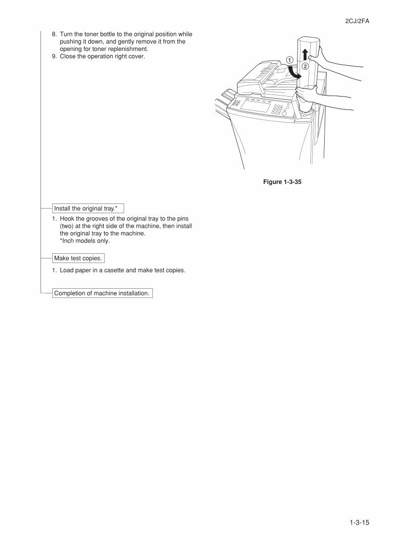
1-3-15
2CJ/2FA
8. Turn the toner bottle to the original position whilepushing it down, and gently remove it from theopening for toner replenishment.
9. Close the operation right cover.
1. Hook the grooves of the original tray to the pins(two) at the right side of the machine, then installthe original tray to the machine.*Inch models only.
1. Load paper in a casette and make test copies.
Install the original tray.*
Make test copies.
Completion of machine installation.
Figure 1-3-35
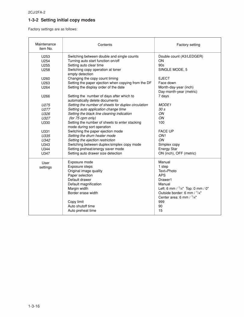
1-3-16
2CJ/2FA-2
1-3-2 Setting initial copy modes
Factory settings are as follows:
Maintenance item No.
Usersettings
Contents Factory setting
U253U254U255U258
U260U263U264
U266
U275U277U326U327U330
U331U335U342U343U344U347
Switching between double and single countsTurning auto start function on/offSetting auto clear timeSwitching copy operation at toner empty detectionChanging the copy count timingSetting the paper ejection when copying from the DFSetting the display order of the date
Setting the number of days after which to automatically delete documentsSetting the number of sheets for duplex circulationSetting auto application change timeSetting the black line cleaning indication (for 75 cpm only)Setting the number of sheets to enter stacking mode during sort operationSwitching the paper ejection modeSetting the drum heater modeSetting the ejection restrictionSwitching between duplex/simplex copy modeSetting preheat/energy saver modeSetting auto drawer size detection
Exposure modeExposure stepsOriginal image qualityPaper selectionDefault drawerDefault magnificationMargin widthBorder erase width
Copy limitAuto shutoff timeAuto preheat time
Double count (A3/LEDGER)ON90sSINGLE MODE, 5
EJECTFace downMonth-day-year (inch) Day-month-year (metric)7 days
MODE130 sONON100
FACE UPON1ONSimplex copyEnergy StarON (inch), OFF (metric)
Manual1 stepText+PhotoAPSDrawer1ManualLeft: 6 mm / 1/4" Top: 0 mm / 0"Outside border: 6 mm / 1/4"Center area: 6 mm / 1/4"9999015
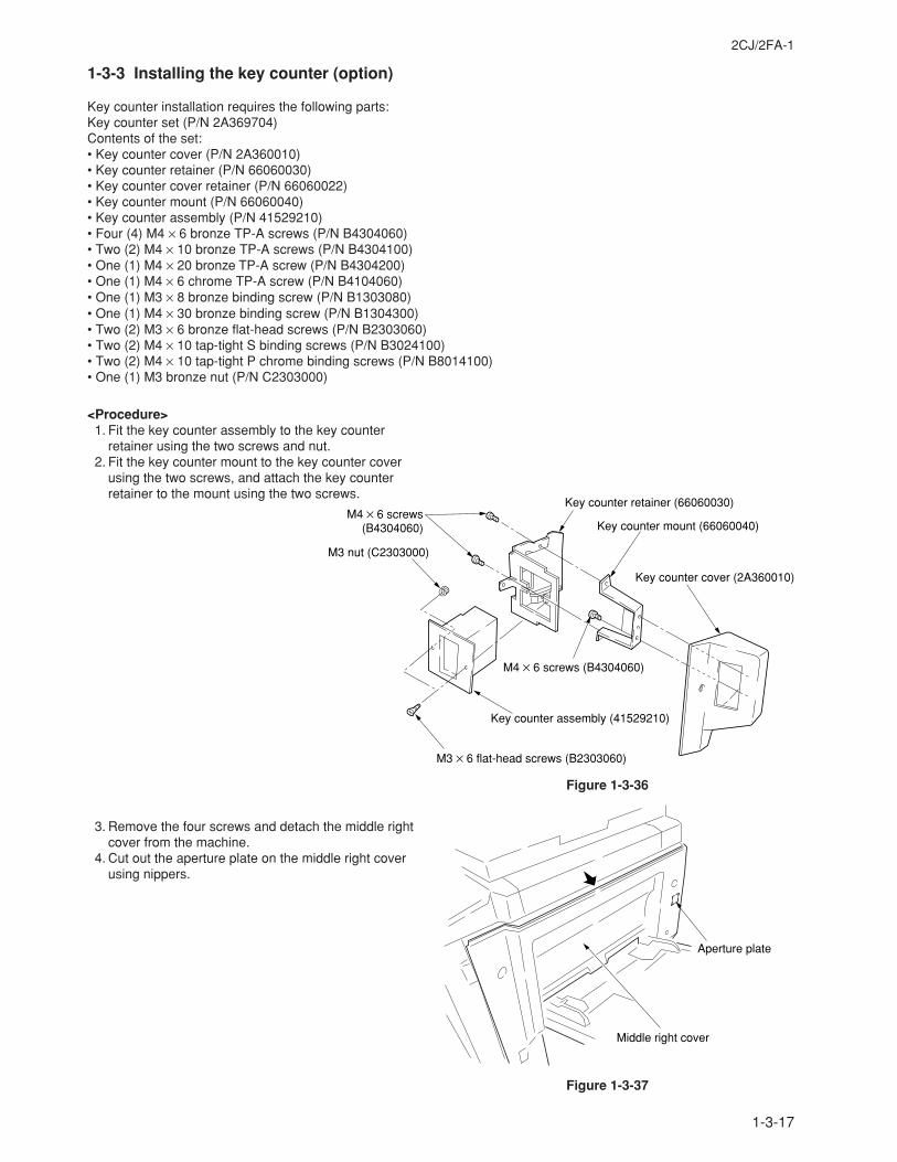
1-3-17
2CJ/2FA-1
1-3-3 Installing the key counter (option)
Key counter installation requires the following parts:Key counter set (P/N 2A369704)Contents of the set:• Key counter cover (P/N 2A360010)• Key counter retainer (P/N 66060030)• Key counter cover retainer (P/N 66060022)• Key counter mount (P/N 66060040)• Key counter assembly (P/N 41529210)• Four (4) M4 × 6 bronze TP-A screws (P/N B4304060)• Two (2) M4 × 10 bronze TP-A screws (P/N B4304100)• One (1) M4 × 20 bronze TP-A screw (P/N B4304200)• One (1) M4 × 6 chrome TP-A screw (P/N B4104060)• One (1) M3 × 8 bronze binding screw (P/N B1303080)• One (1) M4 × 30 bronze binding screw (P/N B1304300)• Two (2) M3 × 6 bronze flat-head screws (P/N B2303060)• Two (2) M4 × 10 tap-tight S binding screws (P/N B3024100)• Two (2) M4 × 10 tap-tight P chrome binding screws (P/N B8014100)• One (1) M3 bronze nut (P/N C2303000)
<Procedure> 1. Fit the key counter assembly to the key counter
retainer using the two screws and nut. 2. Fit the key counter mount to the key counter cover
using the two screws, and attach the key counterretainer to the mount using the two screws.
3. Remove the four screws and detach the middle rightcover from the machine.
4. Cut out the aperture plate on the middle right coverusing nippers.
M3 × 6 flat-head screws (B2303060)
M4 × 6 screws (B4304060)
M3 nut (C2303000)
Key counter retainer (66060030)
Key counter mount (66060040)
Key counter cover (2A360010)
M4 × 6 screws (B4304060)
Key counter assembly (41529210)
Figure 1-3-36
Middle right cover
Aperture plate
Figure 1-3-37
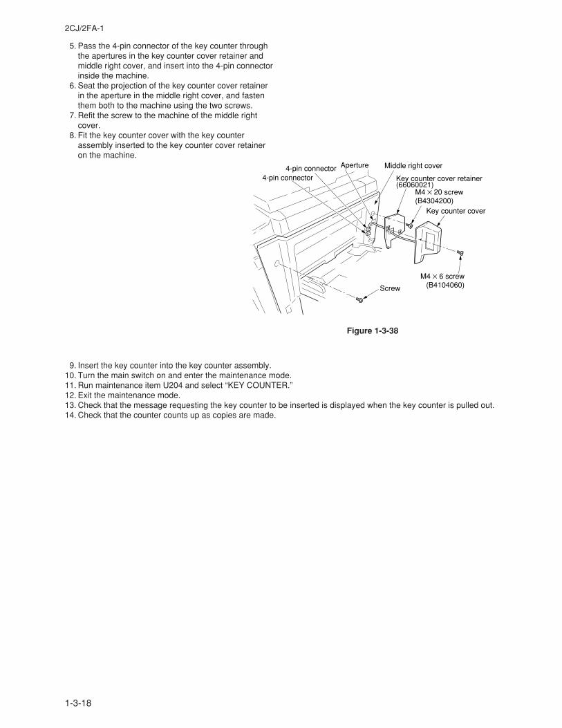
1-3-18
2CJ/2FA-1
5. Pass the 4-pin connector of the key counter throughthe apertures in the key counter cover retainer andmiddle right cover, and insert into the 4-pin connectorinside the machine.
6. Seat the projection of the key counter cover retainerin the aperture in the middle right cover, and fastenthem both to the machine using the two screws.
7. Refit the screw to the machine of the middle rightcover.
8. Fit the key counter cover with the key counterassembly inserted to the key counter cover retaineron the machine.
4-pin connector4-pin connector Aperture Middle right cover
Key counter cover retainer (66060021)
M4 × 20 screw (B4304200)
Key counter cover
M4 × 6 screw (B4104060)Screw
Figure 1-3-38
9. Insert the key counter into the key counter assembly.10. Turn the main switch on and enter the maintenance mode.11. Run maintenance item U204 and select “KEY COUNTER.”12. Exit the maintenance mode.13. Check that the message requesting the key counter to be inserted is displayed when the key counter is pulled out.14. Check that the counter counts up as copies are made.
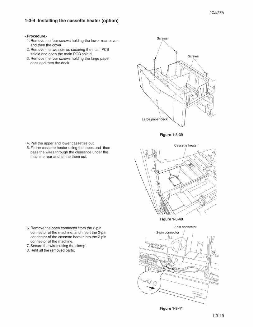
1-3-19
2CJ/2FA
1-3-4 Installing the cassette heater (option)
<Procedure> 1. Remove the four screws holding the lower rear cover
and then the cover. 2. Remove the two screws securing the main PCB
shield and open the main PCB shield. 3. Remove the four screws holding the large paper
deck and then the deck.
4. Pull the upper and lower cassettes out. 5. Fit the cassette heater using the tapes and then
pass the wires through the clearance under themachine rear and let the them out.
6. Remove the open connector from the 2-pinconnector of the machine, and insert the 2-pinconnector of the cassette heater into the 2-pinconnector of the machine.
7. Secure the wires using the clamp. 8. Refit all the removed parts.
Screws
Screws
Large paper deck
Cassette heater
2-pin connector
2-pin connector
Figure 1-3-39
Figure 1-3-40
Figure 1-3-41
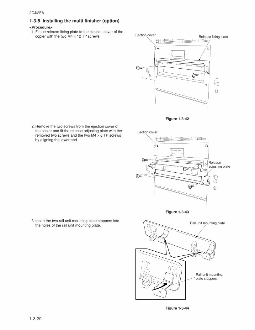
1-3-20
2CJ/2FA
1-3-5 Installing the multi finisher (option)<Procedure> 1. Fit the release fixing plate to the ejection cover of the
copier with the two M4 × 12 TP screws.
2. Remove the two screws from the ejection cover ofthe copier and fit the release adjusting plate with theremoved two screws and the two M4 × 6 TP screwsby aligning the lower end.
3. Insert the two rail unit mounting plate stoppers intothe holes of the rail unit mounting plate.
Figure 1-3-42
Figure 1-3-43
Figure 1-3-44
Ejection cover Release fixing plate
Ejection cover
Releaseadjusting plate
Rail unit mounting plate
Rail unit mounting plate stoppers
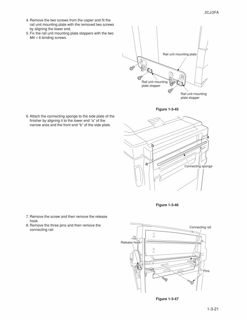
1-3-21
2CJ/2FA
4. Remove the two screws from the copier and fit therail unit mounting plate with the removed two screwsby aligning the lower end.
5. Fix the rail unit mounting plate stoppers with the twoM4 × 6 binding screws.
6. Attach the connecting sponge to the side plate of thefinisher by aligning it to the lower end “a” of thenarrow area and the front end “b” of the side plate.
7. Remove the screw and then remove the releasehook.
8. Remove the three pins and then remove theconnecting rail.
Figure 1-3-45
Figure 1-3-46
Figure 1-3-47
Rail unit mounting plate
Rail unit mounting plate stopper
Rail unit mounting plate stopper
b
a
aConnecting sponge
Connecting rail
Pins
Release hook
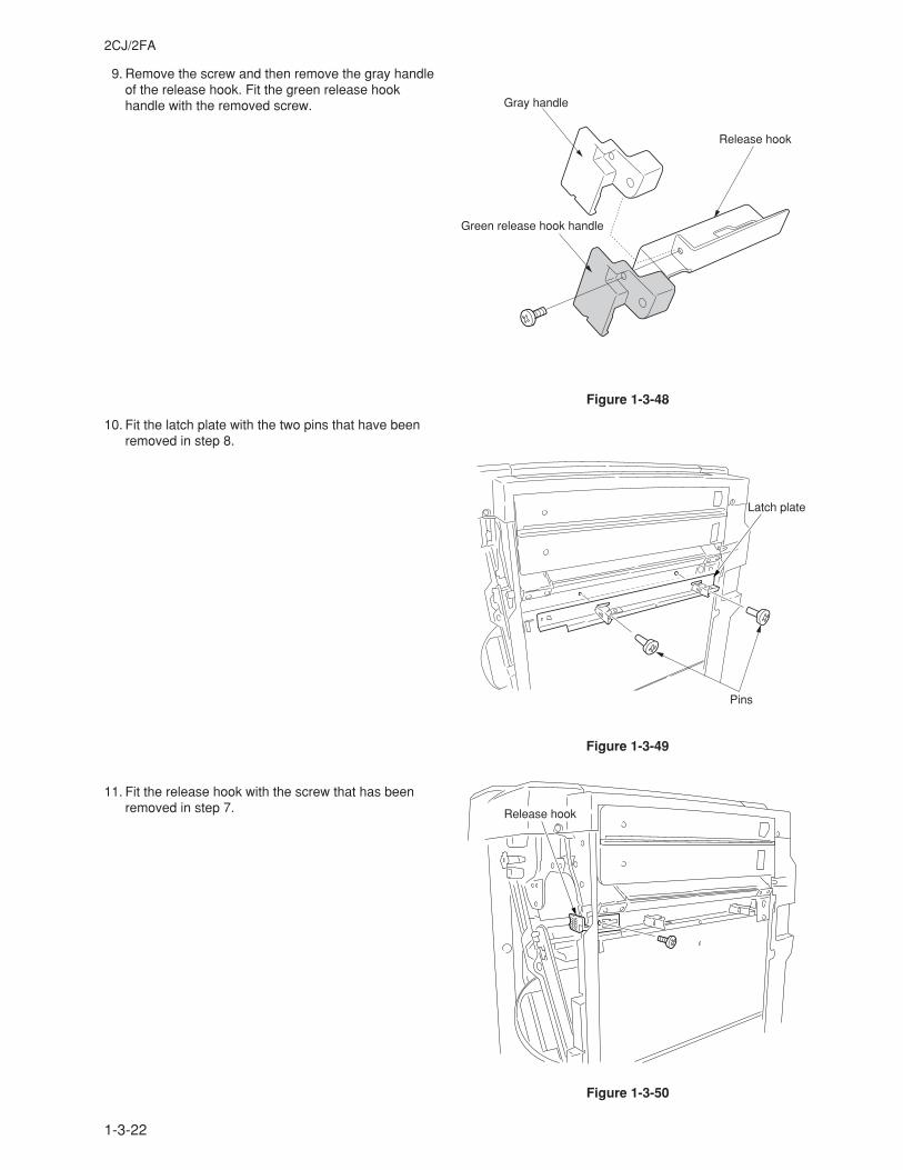
1-3-22
2CJ/2FA
9. Remove the screw and then remove the gray handleof the release hook. Fit the green release hookhandle with the removed screw.
10. Fit the latch plate with the two pins that have beenremoved in step 8.
11. Fit the release hook with the screw that has beenremoved in step 7.
Figure 1-3-48
Figure 1-3-49
Figure 1-3-50
Gray handle
Release hook
Green release hook handle
Latch plate
Pins
Release hook
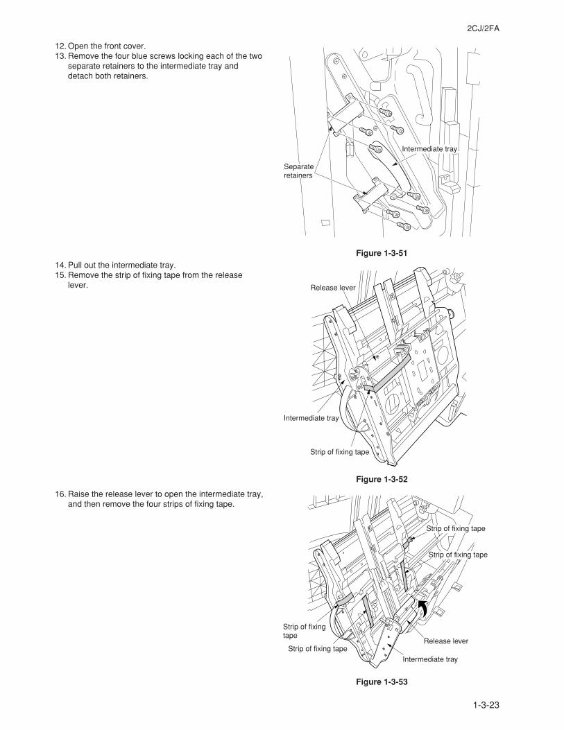
1-3-23
2CJ/2FA
12. Open the front cover.13. Remove the four blue screws locking each of the two
separate retainers to the intermediate tray anddetach both retainers.
14. Pull out the intermediate tray.15. Remove the strip of fixing tape from the release
lever.
16. Raise the release lever to open the intermediate tray,and then remove the four strips of fixing tape.
Figure 1-3-51
Figure 1-3-52
Figure 1-3-53
Intermediate tray
Separate retainers
Release lever
Intermediate tray
Strip of fixing tape
Strip of fixing tape
Strip of fixing tape
Release lever
Intermediate tray
Strip of fixing tape
Strip of fixing tape
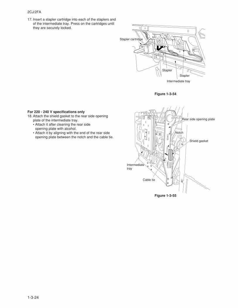
1-3-24
2CJ/2FA
17. Insert a stapler cartridge into each of the staplers andof the intermediate tray. Press on the cartridges untilthey are securely locked.
For 220 - 240 V specifications only18. Attach the shield gasket to the rear side opening
plate of the intermediate tray.• Attach it after cleaning the rear side
opening plate with alcohol.• Attach it by aligning with the end of the rear side
opening plate between the notch and the cable tie.
Figure 1-3-55
Figure 1-3-54
Intermediate tray
Stapler
Stapler
Stapler cartridge
Shield gasket
Rear side opening plate
Notch
Cable tie
Intermediate tray
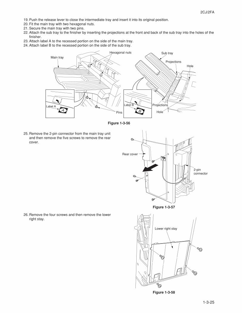
1-3-25
2CJ/2FA
19. Push the release lever to close the intermediate tray and insert it into its original position.20. Fit the main tray with two hexagonal nuts.21. Secure the main tray with two pins.22. Attach the sub tray to the finisher by inserting the projections at the front and back of the sub tray into the holes of the
finisher.23. Attach label A to the recessed portion on the side of the main tray.24. Attach label B to the recessed portion on the side of the sub tray.
25. Remove the 2-pin connector from the main tray unitand then remove the five screws to remove the rearcover.
26. Remove the four screws and then remove the lowerright stay.
Figure 1-3-57
Figure 1-3-58
Main tray
Hexagonal nuts
Pins
Sub tray
Projections
Hole
Hole
Label A Label B Projections
2-pin connector
Rear cover
Lower right stay
Figure 1-3-56
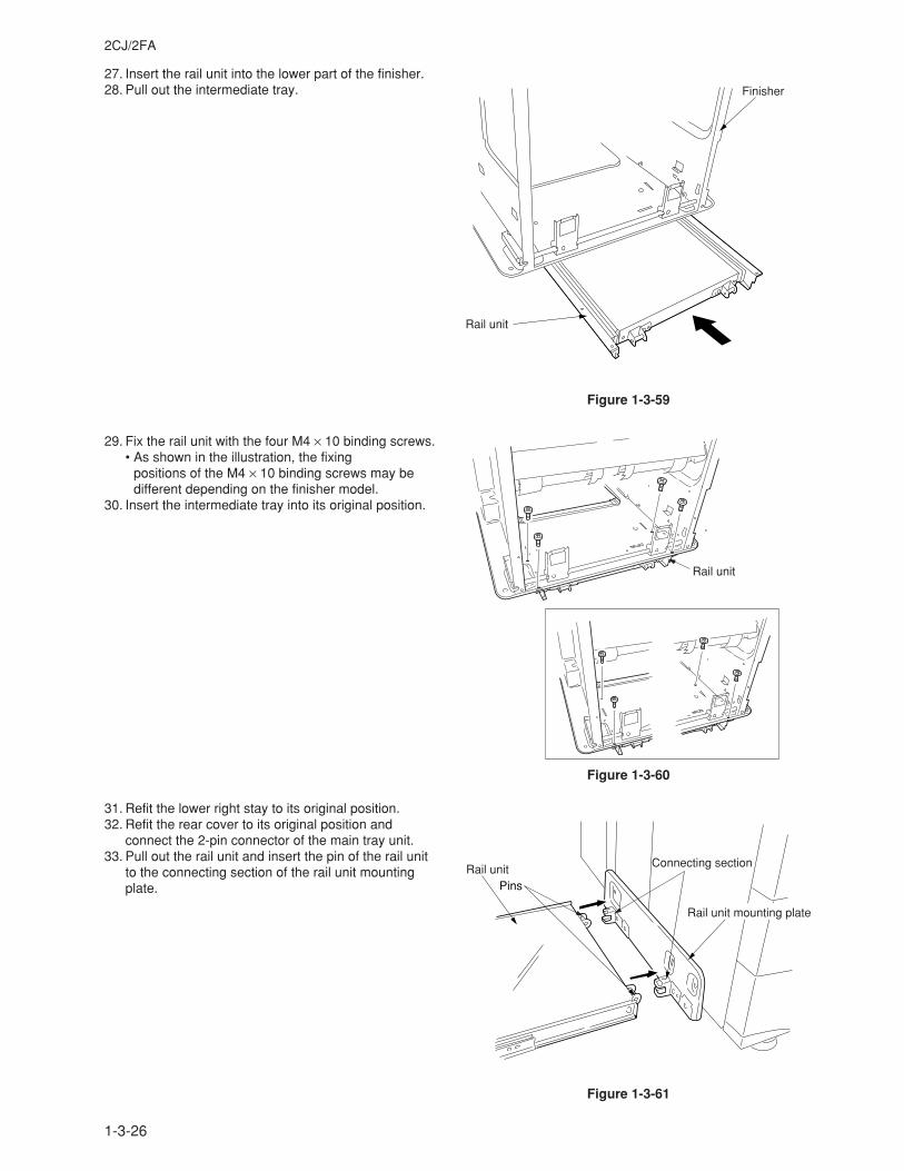
1-3-26
2CJ/2FA
27. Insert the rail unit into the lower part of the finisher.28. Pull out the intermediate tray.
29. Fix the rail unit with the four M4 × 10 binding screws.• As shown in the illustration, the fixing
positions of the M4 × 10 binding screws may bedifferent depending on the finisher model.
30. Insert the intermediate tray into its original position.
31. Refit the lower right stay to its original position.32. Refit the rear cover to its original position and
connect the 2-pin connector of the main tray unit.33. Pull out the rail unit and insert the pin of the rail unit
to the connecting section of the rail unit mountingplate.
Figure 1-3-59
Figure 1-3-60
Figure 1-3-61
Finisher
Rail unit
Rail unit
Connecting section
PinsRail unit
Rail unit mounting plate
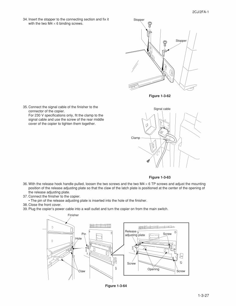
1-3-27
2CJ/2FA-1
34. Insert the stopper to the connecting section and fix itwith the two M4 × 6 binding screws.
35. Connect the signal cable of the finisher to theconnector of the copier.For 230 V specifications only, fit the clamp to thesignal cable and use the screw of the rear middlecover of the copier to tighten them together.
Figure 1-3-62
Figure 1-3-63
Figure 1-3-64
36. With the release hook handle pulled, loosen the two screws and the two M4 × 6 TP screws and adjust the mountingposition of the release adjusting plate so that the claw of the latch plate is positioned at the center of the opening ofthe release adjusting plate.
37. Connect the finisher to the copier.• The pin of the release adjusting plate is inserted into the hole of the finisher.
38. Close the front cover.39. Plug the copier’s power cable into a wall outlet and turn the copier on from the main switch.
Stopper
Stopper
Signal cable
Clamp
Opening
Screw
Screw
ScrewPin
Hole
Claw
Finisher
Release adjusting plate
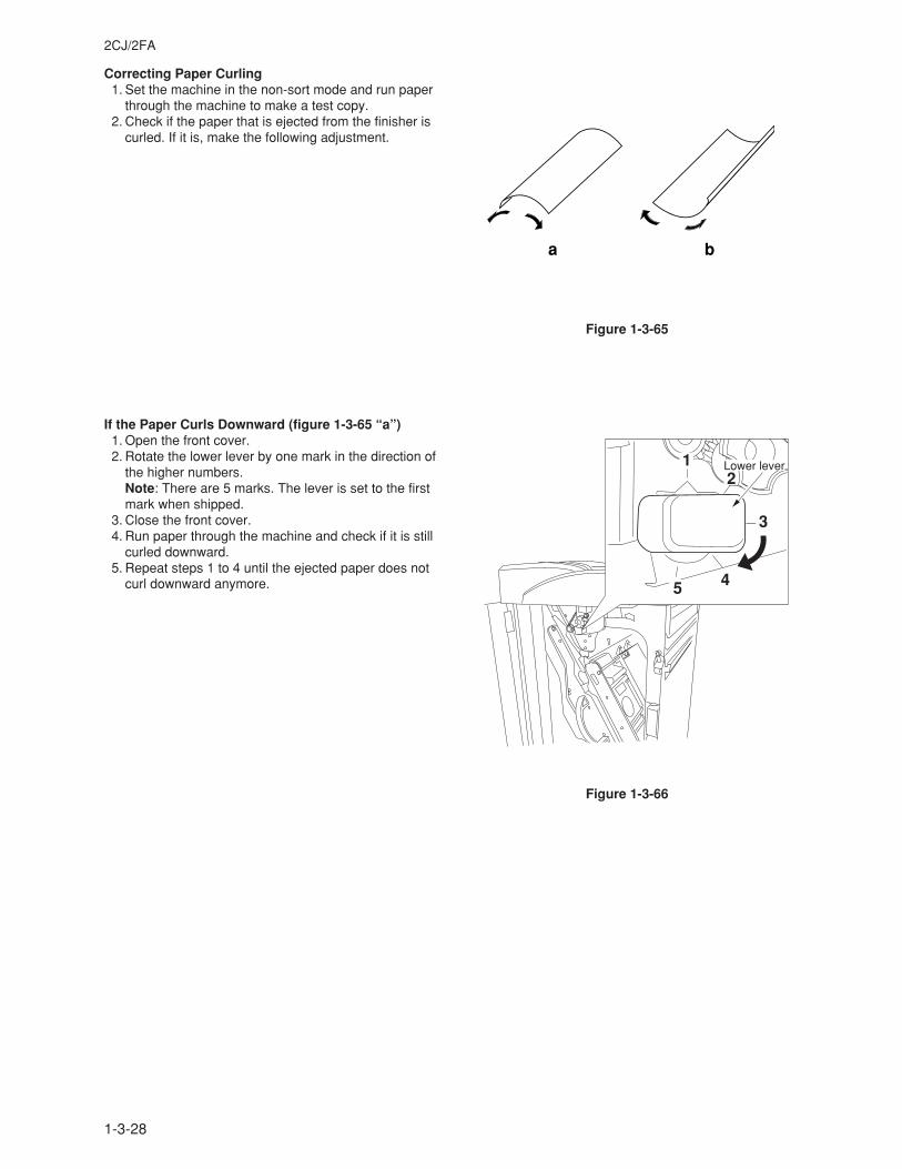
1-3-28
2CJ/2FA
Correcting Paper Curling 1. Set the machine in the non-sort mode and run paper
through the machine to make a test copy. 2. Check if the paper that is ejected from the finisher is
curled. If it is, make the following adjustment.
If the Paper Curls Downward (figure 1-3-65 “a”) 1. Open the front cover. 2. Rotate the lower lever by one mark in the direction of
the higher numbers.Note: There are 5 marks. The lever is set to the firstmark when shipped.
3. Close the front cover. 4. Run paper through the machine and check if it is still
curled downward. 5. Repeat steps 1 to 4 until the ejected paper does not
curl downward anymore.
Figure 1-3-66
Figure 1-3-65
a b
12
3
45
Lower lever
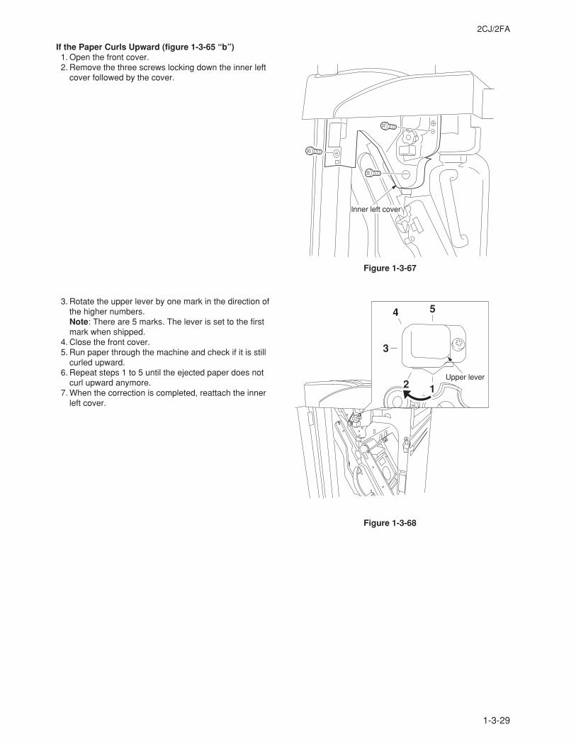
1-3-29
2CJ/2FA
If the Paper Curls Upward (figure 1-3-65 “b”) 1. Open the front cover. 2. Remove the three screws locking down the inner left
cover followed by the cover.
3. Rotate the upper lever by one mark in the direction ofthe higher numbers.Note: There are 5 marks. The lever is set to the firstmark when shipped.
4. Close the front cover. 5. Run paper through the machine and check if it is still
curled upward. 6. Repeat steps 1 to 5 until the ejected paper does not
curl upward anymore. 7. When the correction is completed, reattach the inner
left cover.
Figure 1-3-68
Figure 1-3-67
Inner left cover
Upper lever
1
54
3
2
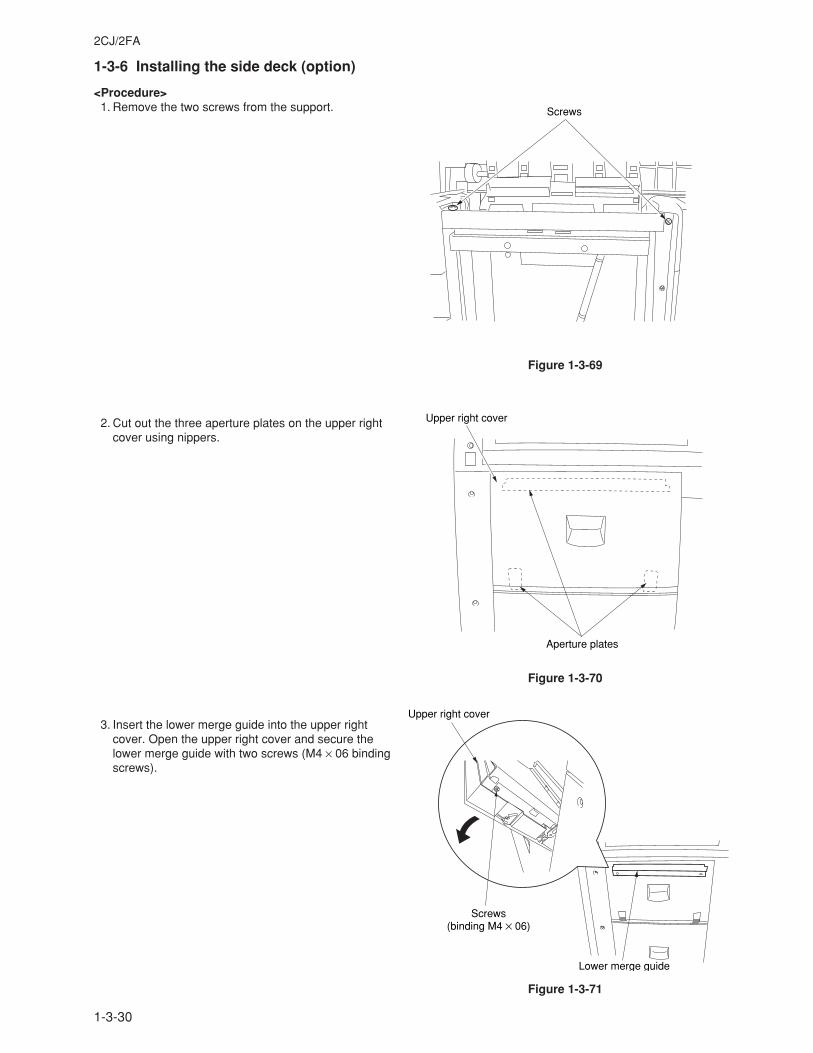
1-3-30
2CJ/2FA
1-3-6 Installing the side deck (option)
<Procedure> 1. Remove the two screws from the support.
2. Cut out the three aperture plates on the upper rightcover using nippers.
3. Insert the lower merge guide into the upper rightcover. Open the upper right cover and secure thelower merge guide with two screws (M4 × 06 bindingscrews).
Screws
Figure 1-3-69
Aperture plates
Upper right cover
Figure 1-3-70
Lower merge guide
Screws(binding M4 × 06)
Upper right cover
Figure 1-3-71
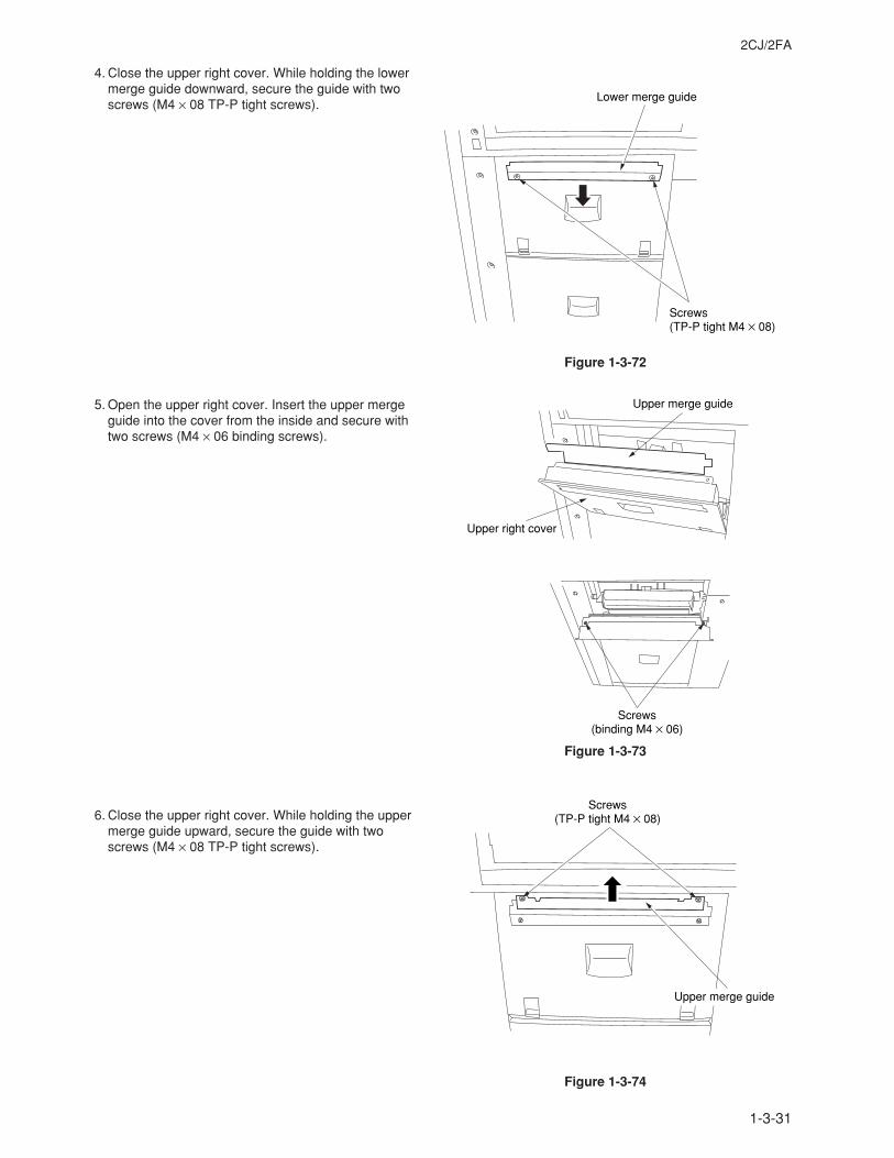
1-3-31
2CJ/2FA
4. Close the upper right cover. While holding the lowermerge guide downward, secure the guide with twoscrews (M4 × 08 TP-P tight screws).
5. Open the upper right cover. Insert the upper mergeguide into the cover from the inside and secure withtwo screws (M4 × 06 binding screws).
6. Close the upper right cover. While holding the uppermerge guide upward, secure the guide with twoscrews (M4 × 08 TP-P tight screws).
Figure 1-3-72
Lower merge guide
Screws(TP-P tight M4 × 08)
Upper merge guide
Upper right cover
Screws(binding M4 × 06)
Figure 1-3-73
Upper merge guide
Screws(TP-P tight M4 × 08)
Figure 1-3-74
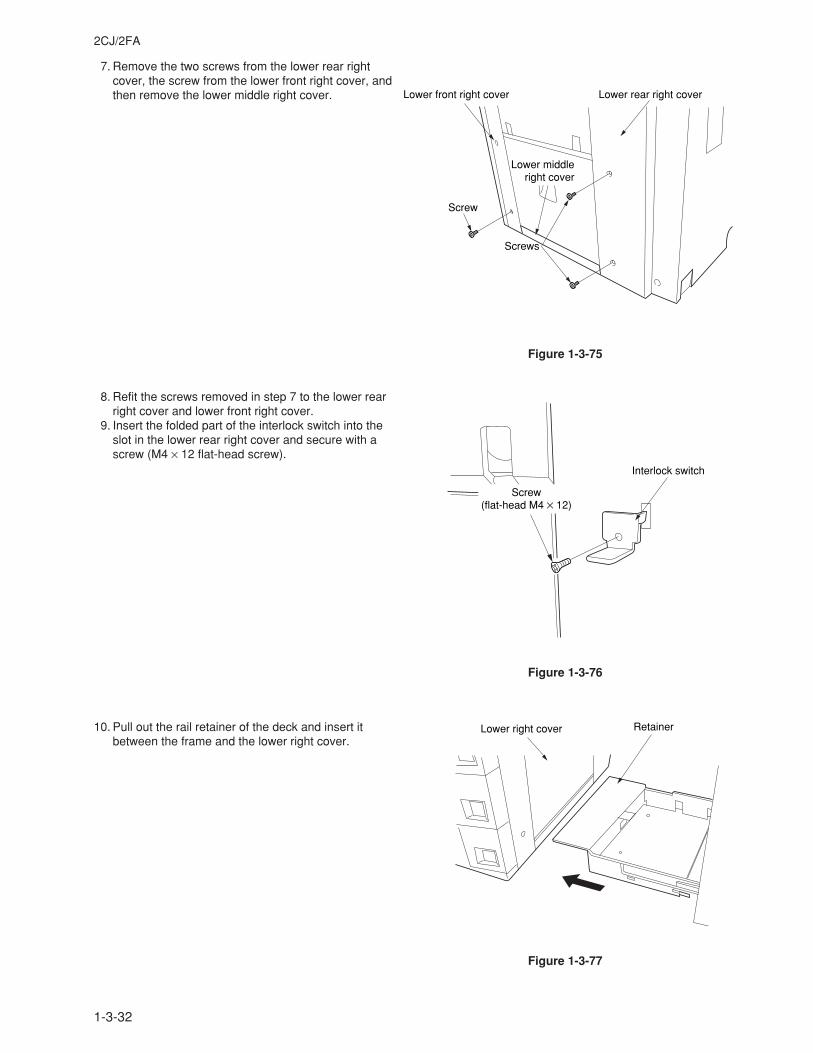
1-3-32
2CJ/2FA
7. Remove the two screws from the lower rear rightcover, the screw from the lower front right cover, andthen remove the lower middle right cover.
8. Refit the screws removed in step 7 to the lower rearright cover and lower front right cover.
9. Insert the folded part of the interlock switch into theslot in the lower rear right cover and secure with ascrew (M4 × 12 flat-head screw).
10. Pull out the rail retainer of the deck and insert itbetween the frame and the lower right cover.
Screws
Screw
Lower middleright cover
Lower front right cover Lower rear right cover
Figure 1-3-75
Interlock switch
Screw(flat-head M4 × 12)
Figure 1-3-76
RetainerLower right cover
Figure 1-3-77
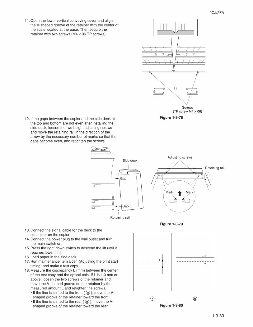
1-3-33
2CJ/2FA
11. Open the lower vertical conveying cover and alignthe V-shaped groove of the retainer with the center ofthe scale located at the base. Then secure theretainer with two screws (M4 × 06 TP screws).
12. If the gaps between the copier and the side deck atthe top and bottom are not even after installing theside deck, loosen the two height adjusting screwsand move the retaining rail in the direction of thearrow by the necessary number of marks so that thegaps become even, and retighten the screws.
13. Connect the signal cable for the deck to theconnector on the copier.
14. Connect the power plug to the wall outlet and turnthe main switch on.
15. Press the right down switch to descend the lift until itreaches lower limit.
16. Load paper in the side deck.17. Run maintenance item U034 (Adjusting the print start
timing) and make a test copy.18. Measure the discrepancy L (mm) between the center
of the test copy and the optical axis. If L is 1.0 mm orabove, loosen the two screws of the retainer andmove the V-shaped groove on the retainer by themeasured amount L and retighten the screws.• If the line is shifted to the front ( a ), move the V-
shaped groove of the retainer toward the front.• If the line is shifted to the rear ( b ), move the V-
shaped groove of the retainer toward the rear.
Figure 1-3-79
Screws(TP screw M4 × 06)
Figure 1-3-80
a b
LL
Side deckAdjusting screws
Retaining rail
Retaining rail
Mark Mark
Gap
Gap
Figure 1-3-78
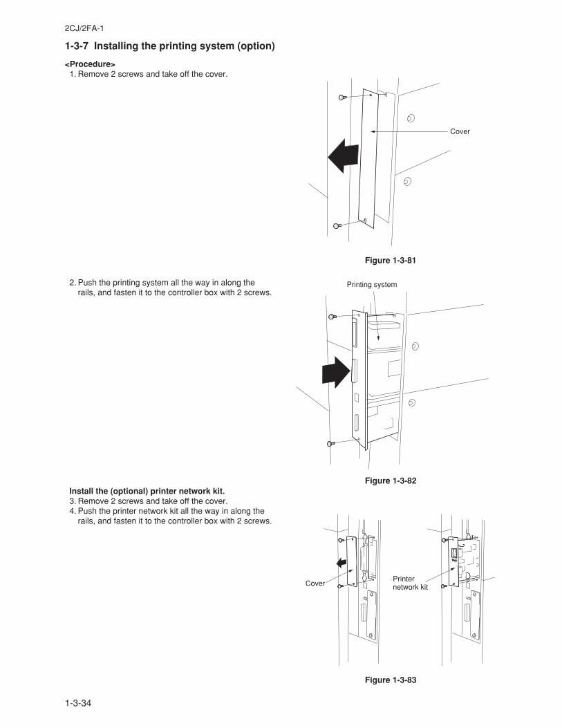
1-3-34
2CJ/2FA-1
1-3-7 Installing the printing system (option)
<Procedure> 1. Remove 2 screws and take off the cover.
2. Push the printing system all the way in along therails, and fasten it to the controller box with 2 screws.
Install the (optional) printer network kit. 3. Remove 2 screws and take off the cover. 4. Push the printer network kit all the way in along the
rails, and fasten it to the controller box with 2 screws.
Figure 1-3-81
Figure 1-3-82
Figure 1-3-83
Cover
Printing system
CoverPrinter network kit
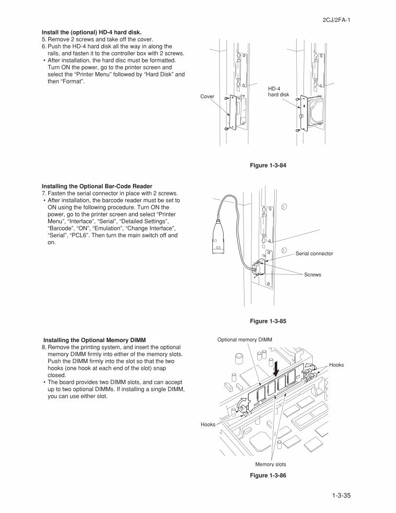
1-3-35
2CJ/2FA-1
Install the (optional) HD-4 hard disk. 5. Remove 2 screws and take off the cover. 6. Push the HD-4 hard disk all the way in along the
rails, and fasten it to the controller box with 2 screws. • After installation, the hard disc must be formatted.
Turn ON the power, go to the printer screen andselect the “Printer Menu” followed by “Hard Disk” andthen “Format”.
Installing the Optional Bar-Code Reader 7. Fasten the serial connector in place with 2 screws. • After installation, the barcode reader must be set to
ON using the following procedure. Turn ON thepower, go to the printer screen and select “PrinterMenu”, “Interface”, “Serial”, “Detailed Settings”,“Barcode”, “ON”, “Emulation”, “Change Interface”,“Serial”, “PCL6”. Then turn the main switch off andon.
Installing the Optional Memory DIMM 8. Remove the printing system, and insert the optional
memory DIMM firmly into either of the memory slots.Push the DIMM firmly into the slot so that the twohooks (one hook at each end of the slot) snapclosed.
• The board provides two DIMM slots, and can acceptup to two optional DIMMs. If installing a single DIMM,you can use either slot.
Figure 1-3-84
Figure 1-3-85
Figure 1-3-86
Cover
HD-4 hard disk
Serial connector
Screws
Optional memory DIMM
Memory slots
Hooks
Hooks
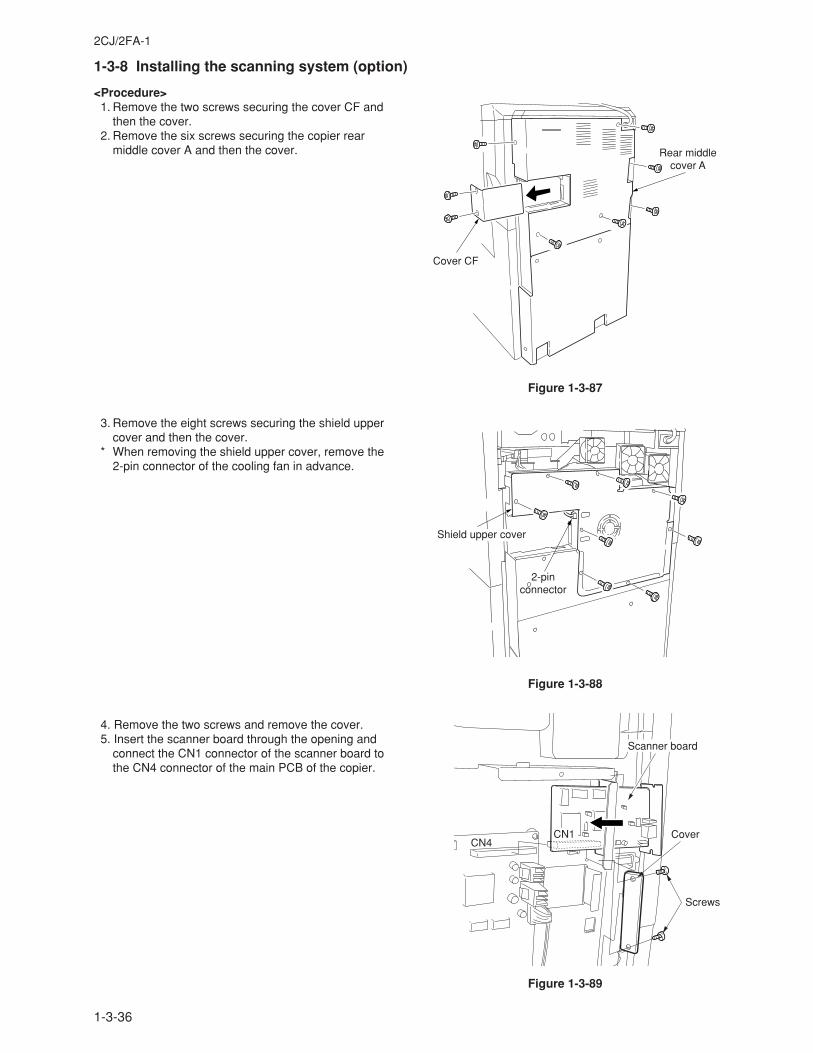
1-3-36
2CJ/2FA-1
1-3-8 Installing the scanning system (option)
<Procedure> 1. Remove the two screws securing the cover CF and
then the cover. 2. Remove the six screws securing the copier rear
middle cover A and then the cover.
3. Remove the eight screws securing the shield uppercover and then the cover.
* When removing the shield upper cover, remove the2-pin connector of the cooling fan in advance.
4. Remove the two screws and remove the cover. 5. Insert the scanner board through the opening and
connect the CN1 connector of the scanner board tothe CN4 connector of the main PCB of the copier.
Cover CF
Rear middle cover A
Figure 1-3-87
Shield upper cover
2-pinconnector
Figure 1-3-88
CN1CN4
Scanner board
Cover
Screws
Figure 1-3-89
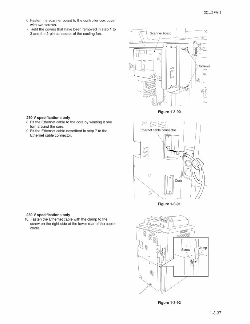
1-3-37
2CJ/2FA-1
6. Fasten the scanner board to the controller-box coverwith two screws.
7. Refit the covers that have been removed in step 1 to3 and the 2-pin connector of the cooling fan.
230 V specifications only 8. Fit the Ethernet cable to the core by winding it one
turn around the core. 9. Fit the Ethernet cable described in step 7 to the
Ethernet cable connector.
230 V specifications only10. Fasten the Ethernet cable with the clamp to the
screw on the right side at the lower rear of the copiercover.
Scanner board
Screws
Core
Ethernet cable connector
Screw Clamp
Figure 1-3-90
Figure 1-3-91
Figure 1-3-92
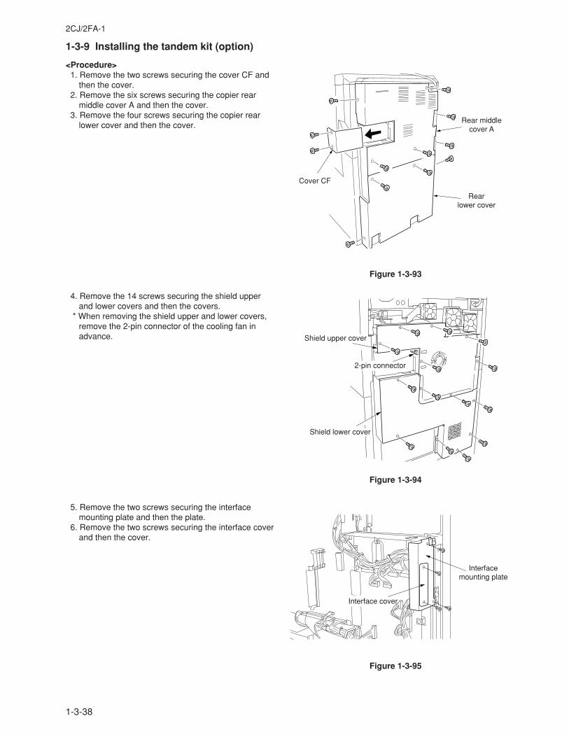
1-3-38
2CJ/2FA-1
1-3-9 Installing the tandem kit (option)
<Procedure> 1. Remove the two screws securing the cover CF and
then the cover. 2. Remove the six screws securing the copier rear
middle cover A and then the cover. 3. Remove the four screws securing the copier rear
lower cover and then the cover.
4. Remove the 14 screws securing the shield upperand lower covers and then the covers.
* When removing the shield upper and lower covers,remove the 2-pin connector of the cooling fan inadvance.
5. Remove the two screws securing the interfacemounting plate and then the plate.
6. Remove the two screws securing the interface coverand then the cover.
Cover CF
Rear middlecover A
Rearlower cover
Figure 1-3-93
Shield upper cover
Shield lower cover
2-pin connector
Figure 1-3-94
Interfacemounting plate
Interface cover
Figure 1-3-95
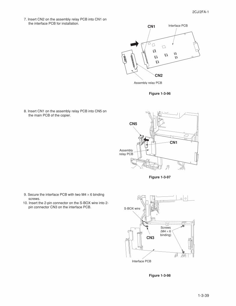
1-3-39
2CJ/2FA-1
7. Insert CN2 on the assembly relay PCB into CN1 onthe interface PCB for installation.
8. Insert CN1 on the assembly relay PCB into CN5 onthe main PCB of the copier.
9. Secure the interface PCB with two M4 × 6 bindingscrews.
10. Insert the 2-pin connector on the S-BOX wire into 2-pin connector CN3 on the interface PCB.
CN1
CN2
Interface PCB
Assembly relay PCB
CN1
CN5
Assemblyrelay PCB
CN3
Interface PCB
S-BOX wire
Screws(M4 × 6binding)
Figure 1-3-96
Figure 1-3-97
Figure 1-3-98
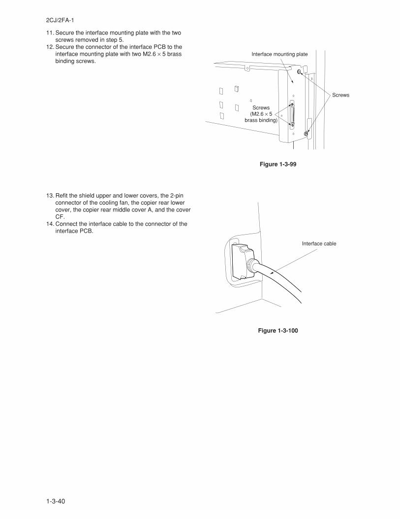
1-3-40
2CJ/2FA-1
11. Secure the interface mounting plate with the twoscrews removed in step 5.
12. Secure the connector of the interface PCB to theinterface mounting plate with two M2.6 × 5 brassbinding screws.
13. Refit the shield upper and lower covers, the 2-pinconnector of the cooling fan, the copier rear lowercover, the copier rear middle cover A, and the coverCF.
14. Connect the interface cable to the connector of theinterface PCB.
Interface mounting plate
Screws
Screws(M2.6 × 5
brass binding)
Interface cable
Figure 1-3-99
Figure 1-3-100
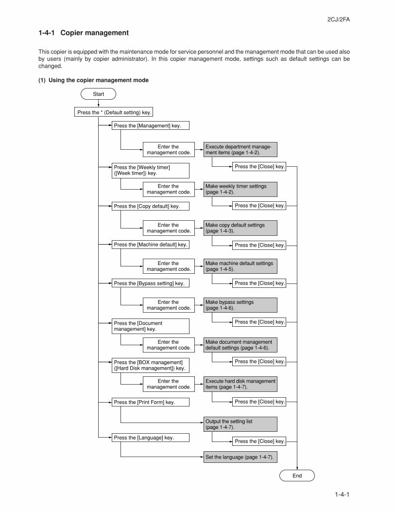
2CJ/2FA
1-4-1
1-4-1 Copier management
This copier is equipped with the maintenance mode for service personnel and the management mode that can be used alsoby users (mainly by copier administrator). In this copier management mode, settings such as default settings can bechanged.
(1) Using the copier management mode
Press the [Management] key.
Press the [Print Form] key.
Press the [Language] key.
Enter the management code.
Press the * (Default setting) key.
Execute department manage-ment items (page 1-4-2).
Press the [Close] key.Press the [Weekly timer]([Week timer]) key.
Press the [Close] key.
Enter the management code.
Make weekly timer settings (page 1-4-2).
Press the [Copy default] key.
Press the [Close] key.
Enter the management code.
Make copy default settings (page 1-4-3).
Output the setting list (page 1-4-7).
Press the [Machine default] key.
Press the [Close] key.
Enter the management code.
Make machine default settings (page 1-4-5).
Press the [Document management] key.
Press the [Close] key.
Enter the management code.
Make document management default settings (page 1-4-6).
Press the [BOX management]([Hard Disk management]) key.
Press the [Close] key.
Enter the management code.
Execute hard disk management items (page 1-4-7).
Press the [Close] key.
Press the [Bypass setting] key.
Press the [Close] key.
Enter the management code.
Make bypass settings(page 1-4-6).
Set the language (page 1-4-7).
Start
End
2CJ/2FA
1-4-2
(2) Setting department management items
Registering a new department code
Sets a department code and the limit of thenumber of copies for that department.
1. Press the [ID-code Reg./Del.] key.2. Press the [Register] key and press the [#
keys].3. Enter a department code (8-digit) using the
numeric keys and press the [# keys].4. Enter the number of copies limit using the
numeric keys. The copy limit can be set to any1 page increment between 1 and 999999.Entering “0” enables unlimited copying.
5. Press the [Close] key.6. Press the [Close] key.7. Press the [On] key.8. Press the [Close] key.
Deleting a department code
1. Press the [ID-code Reg./Del.] key.2. Select the department code to be deleted and
press the [Delete] key.3. Select “Yes” or “No”.4. Press the [Close] key.5. Press the [On] key.6. Press the [Close] key.
Altering the copy limit
1. Press the [# of copy correct] key.2. Select the department code to be altered and
press the [Correction] key.3. Enter the number of copies limit using the
numeric keys. The copy limit can be set to any1 page increment between 1 and 999999.Entering “0” enables unlimited copying.
4. Press the [Close] key.5. Press the [Close] key.6. Press the [On] key.7. Press the [Close] key.
Clearing copy counts
1. Press the [Counter clear] key.2. Select “Yes” or “No”.3. Press the [Close] key.
Viewing copy counts
1. Press the [Counter by ID-code] key.2. View copy counts using the cursor up/down
keys.3. Press the [Close] key.4. Press the [Close] key.
Print management list
1. Press the [Print the list] key.If A4/11" × 81/2" paper is present, the list isautomatically printed out. Otherwise, selectthe paper source and press the start key.
Enabling/disabling department management
1. Select “On” or “Off”.
Enabling/disabling printer department management
1. Select “On” or “Off” under “Printer”.
Setting printer error report
When the printer department management isenabled, if printing is performed with an incorrectdepartment code, an error report can be output.
1. Press the [On] key under “Printer”.2. Press the [Print Err. PRT.] key.3. Press the [On] key.4. Press the [Close] key.
(3) Weekly timer
Setting weekly timer
Sets the time at which the copier is to be turnedON or OFF during each day of the week, orwhether it will be left ON or OFF all day on any ofthose days.
1. Select the day of the week and press the[Change #] key.
2. To set the time at which the copier is to beturned on or off, press the [Select work time]key and press the +/- keys to select thepower-on hour and minute and the power-offhour and minute.To set the copier OFF all day, press the [Allday-OFF] key.To set the copier ON all day, press the [Allday-ON] key.
3. Press the [Close] key.
Canceling the weekly timer function temporarily
1. Select the day of the week and press the[Change #] key.
2. Press the [On] key under “Cancel”.3. Press the [Close] key.
Turning the [weekly timer] key ON/OFF
1. Select “On” or “Off”.
2CJ/2FA
1-4-3
(4) Copy default
Exposure mode
Selects the exposure mode at power-on.1. Select “Exposure mode” and press the
[Change #] key.2. Select “Manual” or “Auto”.
Exposure steps
Sets the number of exposure steps for themanual exposure mode.
1. Select “Exposure steps” and press the[Change #] key.
2. Select “1 step” or “0.5 step”.
Original image quality
Selects the copy quantity mode at power-on.1. Select “Original image quality” (“Image quality
Original”) and press the [Change #] key.2. Select “Text+Photo”, “Photo” or “Text”.
Custom original size (setting No. 1 - No. 4)
Sets the custom original sizes.1. Select one of “Original size” settings (“custom
1” through “custom 4”) and press the [Change#] key.
2. Press the [On] key.3. Press the +/- keys to set Y (width).
Setting range: 2 to 11" (inch specifications)50 to 297 mm (metric specifications)
4. Press the +/- keys to set X (length).Setting range: 2 to 17" (inch specifications)50 to 432 mm (metric specifications)
Eco print
Selects the toner economy mode to beautomatically on or off at power-on.
1. Select “Eco print” and press the [Change #]key.
2. Select “On” or “Off”.
Paper selection
Sets whether the same sized paper as theoriginal to be copied is automatically selected.
1. Select “Paper selection”(“Select paper”) andpress the [Change #] key.
2. Select “APS” or “Default cassette”.
Select paper type (APS)
Specifies paper types to be selected for the autopaper selection mode.
1. Select “Select paper type(APS)” and pressthe [Change #] key.
2. Press the [On] key.3. Select the paper type. (Multiple types can be
selected.)
Default drawer
Sets the drawer to be selected in cases such asafter the reset key is pressed.
1. Select “Default drawer”(“Default cassette”)and press the [Change #] key.
2. Select priority drawer.
Drawer for cover paper
Sets the drawer to be selected for cover paper.1. Select “Drawer for cover paper” and press the
[Change #] key.2. Select the drawer for cover paper.
Default magnification
Selects whether auto magnification selection or100% magnification is to be given priority whenthe sizes of the original and copy paper aredifferent.
1. Select “Default magnification”(“Defaultmode”) and press the [Change #] key.
2. Select “Manual” or “AMS”.
Auto exposure adjustment
Adjusts the exposure for the auto exposuremode.
1. Select “Auto exposure adj. (Auto)” and pressthe [Change #] key.
2. Press the [Lighter] or [Darker] key to adjustdefault setting of copy exposure.Setting range: -3 to +3
Auto exposure adjustment (OCR)
Adjusts the exposure for scanning with OCR inthe scanner mode.
1. Select “Auto exposure adj. (OCR)” and pressthe [Change #] key.
2. Press the [Lighter] or [Darker] key to adjustdefault setting of copy exposure.Setting range: -3 to +3
Manual exposure adjustment (Mixed)
Adjusts the exposure to be used when text andphoto original is selected for the image mode.
1. Select “Manual exp. adj. (Mixed)” and pressthe [Change #] key.
2. Press the [Lighter] or [Darker] key to adjustdefault setting of copy exposure.Setting range: -3 to +3
Manual exposure adjustment (Text)
Adjusts the exposure to be used when textoriginal is selected for the image mode.
1. Select “Manual exp. adj. (Text)” and press the[Change #] key.
2. Press the [Lighter] or [Darker] key to adjustdefault setting of copy exposure.Setting range: -3 to +3
2CJ/2FA-2
1-4-4
Modify Copy
Disables the modify copy function or enables themodify copy function in the default mode.
1. Select “Modify Copy” and press the [Change#] key.
2. Select “On” or “Off” under “Function”.3. Select “On” or “Off” under “Default”.
Job Queue Report
Sets whether or not the job queue report isselected.
1. Select “Job Queue Report” and press the[Change #] key.
2. Select “off”, “On/All copy job” (“On/(Allcopy)”) or “On/reserved” (“On/reserv.job”).
Display register key
Sets whether or not to display the Register key inthe copy operation screen.
1. Select “Display register key” and press the[Change #] key.
2. Select “On” or “Off”.
Black-line correction
Reduces black lines that may be caused whenthe document processor is used.
1. Select “Correct. fine black line” and press the[Change #] key.
2. Select “On” or “Off”.
Customize the base screen (main function)
Changes the layout of the main functions of thebase screen.
1. Select “Customize (Main function)” and pressthe [Change #] key.
2. Change the layout to press [Move ahead] or[Move to behind].
Customize the copy operating screen (add function)
Changes the layout of the functions except themain functions of the copy operating screens.
1. Select “Customize (Add function)” and pressthe [Change #] key.
2. Change the layout to press [ ← ].
Manual exposure adjustment (Photo)
Adjusts the exposure to be used when photooriginal is selected for the image mode.
1. Select “Manual exp. adj. (Photo)” and press the[Change #] key.
2. Press the [Lighter] or [Darker] key to adjustdefault setting of copy exposure.Setting range: -3 to +3
Sort mode
Sets whether or not the sort mode will be thedefault setting in the initial mode.
1. Select “Sort” and press the [Change #] key.2. Select “On” or “Off”.
Auto rotation mode
Sets whether or not the auto rotation mode will bethe default setting in the initial mode.
1. Select “Auto Rotation” and press the [Change#] key.
2. Select “Rotate” or “No Rotate”.
Margin width
Sets the default setting of the margin width for themargin copying.
1. Select “Default margin width” and press the[Change #] key.
2. Press the up, down, right, and left cursor keysto set the default settings.Setting range: 0 to 3/4" (inch specifications)0 to 18 mm (metric specifications)
Border erase width
Sets the default setting of the border erase widthfor the border erase mode.
1. Select “Default erase width” and press the[Change #] key.
2. Press the +/- keys to adjust default erasewidth.Setting range:
Outside border:0 to 3/4" (inch specifications)0 to 18 mm (metric specifications)
Center area:0 to 1 1/2" (inch specifications)0 to 36 mm (metric specifications)
Copy limit
Sets the number of copies limit for multiplecopying.
1. Select “Preset limit” and press the [Change #]key.
2. Press the +/- keys to set copy preset in onejob.Setting range: 1 to 999 copies
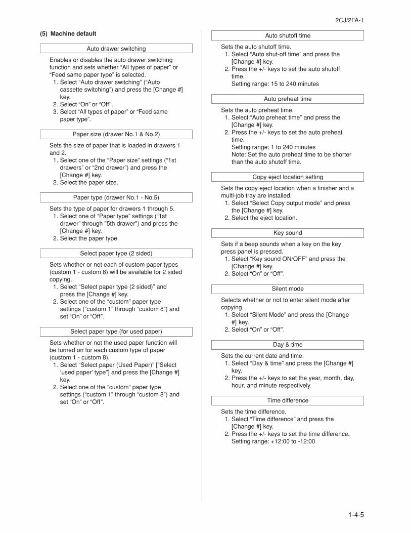
2CJ/2FA-1
1-4-5
Auto shutoff time
Sets the auto shutoff time.1. Select “Auto shut-off time” and press the
[Change #] key.2. Press the +/- keys to set the auto shutoff
time.Setting range: 15 to 240 minutes
Auto preheat time
Sets the auto preheat time.1. Select “Auto preheat time” and press the
[Change #] key.2. Press the +/- keys to set the auto preheat
time.Setting range: 1 to 240 minutesNote: Set the auto preheat time to be shorterthan the auto shutoff time.
Copy eject location setting
Sets the copy eject location when a finisher and amulti-job tray are installed.
1. Select “Select Copy output mode” and pressthe [Change #] key.
2. Select the eject location.
Key sound
Sets if a beep sounds when a key on the keypress panel is pressed.
1. Select “Key sound ON/OFF” and press the[Change #] key.
2. Select “On” or “Off”.
Silent mode
Selects whether or not to enter silent mode aftercopying.
1. Select “Silent Mode” and press the [Change#] key.
2. Select “On” or “Off”.
Day & time
Sets the current date and time.1. Select “Day & time” and press the [Change #]
key.2. Press the +/- keys to set the year, month, day,
hour, and minute respectively.
Time difference
Sets the time difference.1. Select “Time difference” and press the
[Change #] key.2. Press the +/- keys to set the time difference.
Setting range: +12:00 to -12:00
(5) Machine default
Auto drawer switching
Enables or disables the auto drawer switchingfunction and sets whether “All types of paper” or“Feed same paper type” is selected.
1. Select “Auto drawer switching” (“Autocassette switching”) and press the [Change #]key.
2. Select “On” or “Off”.3. Select “All types of paper” or “Feed same
paper type”.
Paper size (drawer No.1 & No.2)
Sets the size of paper that is loaded in drawers 1and 2.
1. Select one of the “Paper size” settings (“1stdrawers” or “2nd drawer”) and press the[Change #] key.
2. Select the paper size.
Paper type (drawer No.1 - No.5)
Sets the type of paper for drawers 1 through 5.1. Select one of “Paper type” settings (“1st
drawer” through "5th drawer") and press the[Change #] key.
2. Select the paper type.
Select paper type (2 sided)
Sets whether or not each of custom paper types(custom 1 - custom 8) will be available for 2 sidedcopying.
1. Select “Select paper type (2 sided)” andpress the [Change #] key.
2. Select one of the “custom” paper typesettings (“custom 1” through “custom 8”) andset “On” or “Off”.
Select paper type (for used paper)
Sets whether or not the used paper function willbe turned on for each custom type of paper(custom 1 - custom 8).
1. Select “Select paper (Used Paper)” [“Select‘used paper’ type”] and press the [Change #]key.
2. Select one of the “custom” paper typesettings (“custom 1” through “custom 8”) andset “On” or “Off”.
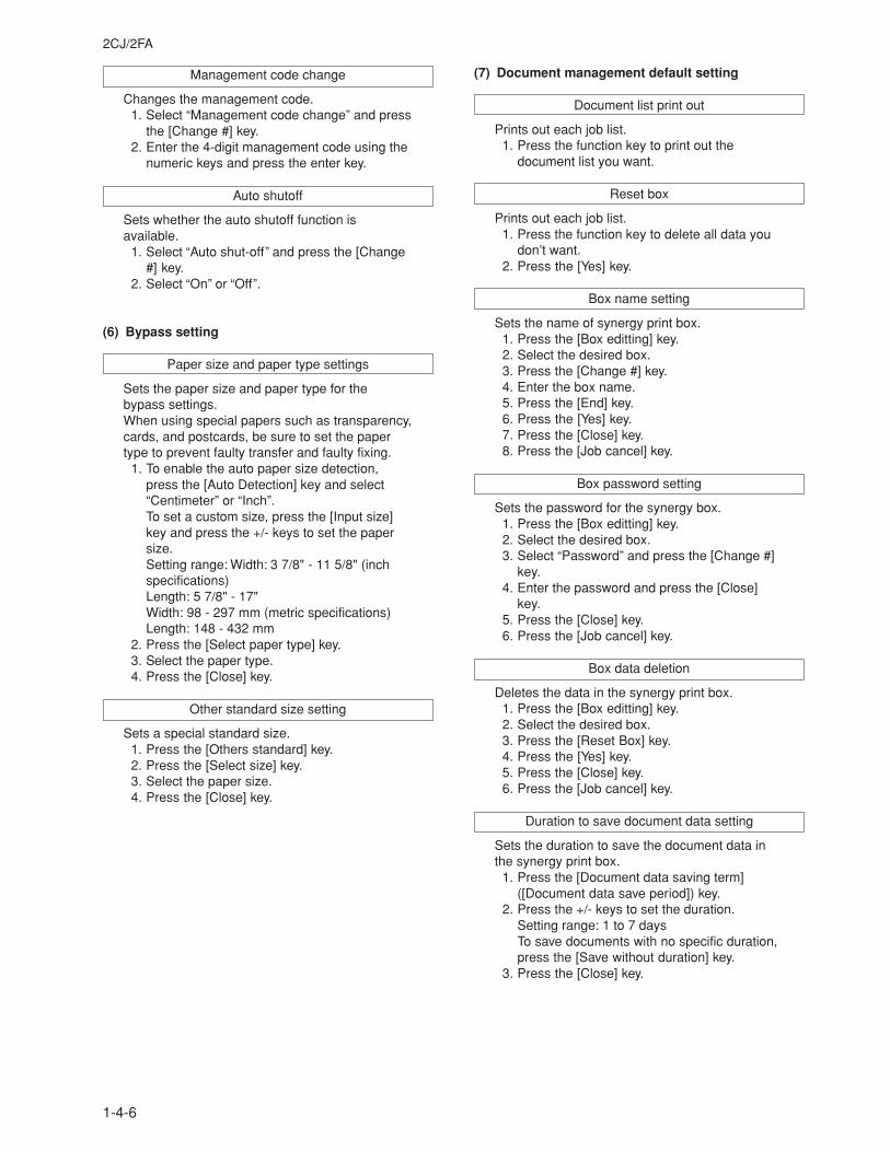
2CJ/2FA
1-4-6
(6) Bypass setting
Paper size and paper type settings
Sets the paper size and paper type for thebypass settings.When using special papers such as transparency,cards, and postcards, be sure to set the papertype to prevent faulty transfer and faulty fixing.
1. To enable the auto paper size detection,press the [Auto Detection] key and select“Centimeter” or “Inch”.To set a custom size, press the [Input size]key and press the +/- keys to set the papersize.Setting range: Width: 3 7/8" - 11 5/8" (inchspecifications)Length: 5 7/8" - 17"Width: 98 - 297 mm (metric specifications)Length: 148 - 432 mm
2. Press the [Select paper type] key.3. Select the paper type.4. Press the [Close] key.
Other standard size setting
Sets a special standard size.1. Press the [Others standard] key.2. Press the [Select size] key.3. Select the paper size.4. Press the [Close] key.
(7) Document management default setting
Document list print out
Prints out each job list.1. Press the function key to print out the
document list you want.
Reset box
Prints out each job list.1. Press the function key to delete all data you
don’t want.2. Press the [Yes] key.
Box name setting
Sets the name of synergy print box.1. Press the [Box editting] key.2. Select the desired box.3. Press the [Change #] key.4. Enter the box name.5. Press the [End] key.6. Press the [Yes] key.7. Press the [Close] key.8. Press the [Job cancel] key.
Box password setting
Sets the password for the synergy box.1. Press the [Box editting] key.2. Select the desired box.3. Select “Password” and press the [Change #]
key.4. Enter the password and press the [Close]
key.5. Press the [Close] key.6. Press the [Job cancel] key.
Box data deletion
Deletes the data in the synergy print box.1. Press the [Box editting] key.2. Select the desired box.3. Press the [Reset Box] key.4. Press the [Yes] key.5. Press the [Close] key.6. Press the [Job cancel] key.
Duration to save document data setting
Sets the duration to save the document data inthe synergy print box.
1. Press the [Document data saving term]([Document data save period]) key.
2. Press the +/- keys to set the duration.Setting range: 1 to 7 daysTo save documents with no specific duration,press the [Save without duration] key.
3. Press the [Close] key.
Management code change
Changes the management code.1. Select “Management code change” and press
the [Change #] key.2. Enter the 4-digit management code using the
numeric keys and press the enter key.
Auto shutoff
Sets whether the auto shutoff function isavailable.
1. Select “Auto shut-off” and press the [Change#] key.
2. Select “On” or “Off”.

2CJ/2FA
1-4-7
(8) Hard disk management
Deletes the invalid data in the hard disk.1. Press the [On] key.2. Press the [Close] key.
(9) Report
Outputs the setting reports.1. Press the [Print form] key.2. Select the report.
Copy report/Option report/Counter report/Machine report
(10) Language
Switches the language to be displayed on thepress panel.
1. Press the [Language] key.2. Select the display language.
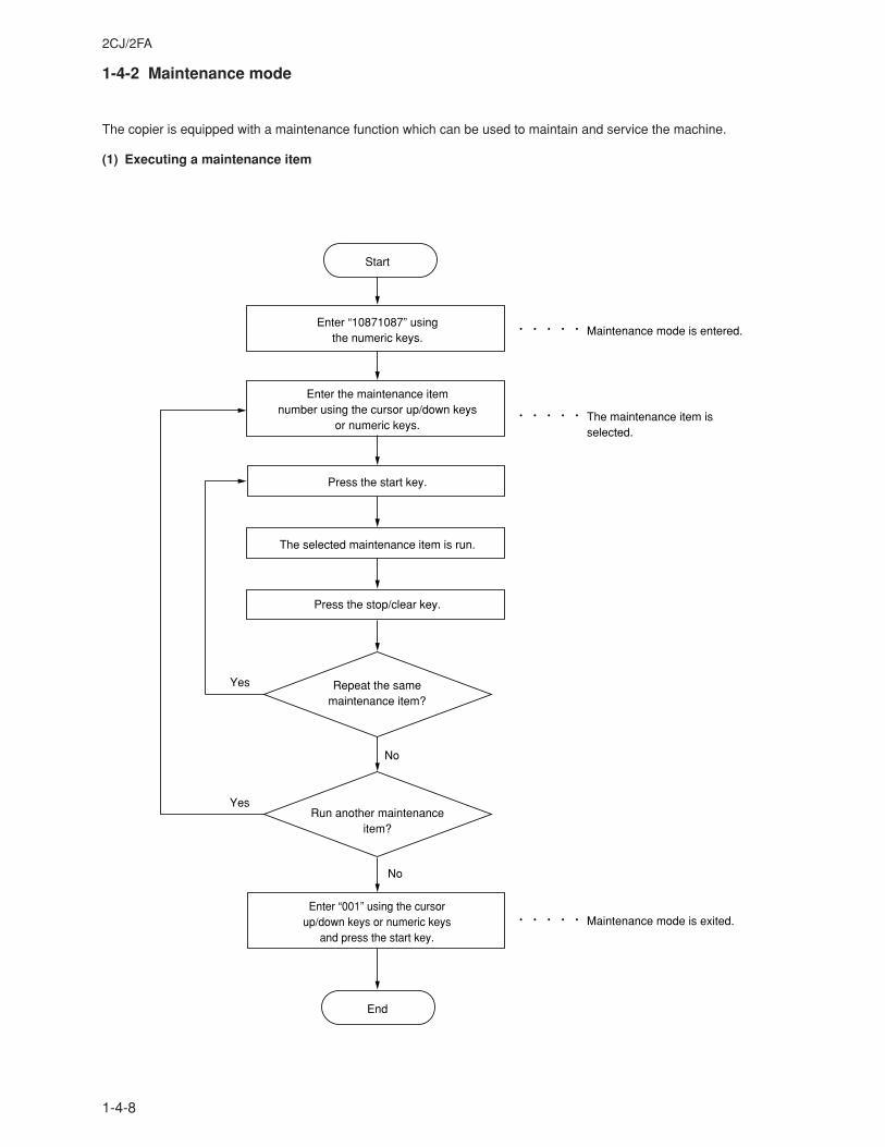
2CJ/2FA
1-4-8
1-4-2 Maintenance mode
The copier is equipped with a maintenance function which can be used to maintain and service the machine.
(1) Executing a maintenance item
Enter “10871087” using the numeric keys.
Enter “001” using the cursor up/down keys or numeric keys
and press the start key.
Enter the maintenance item number using the cursor up/down keys
or numeric keys.
The selected maintenance item is run.
Press the stop/clear key.
Press the start key.
Start
End
Maintenance mode is entered.
The maintenance item is selected.
Maintenance mode is exited.
Repeat the same maintenance item?
Run another maintenance item?
No
No
Yes
Yes
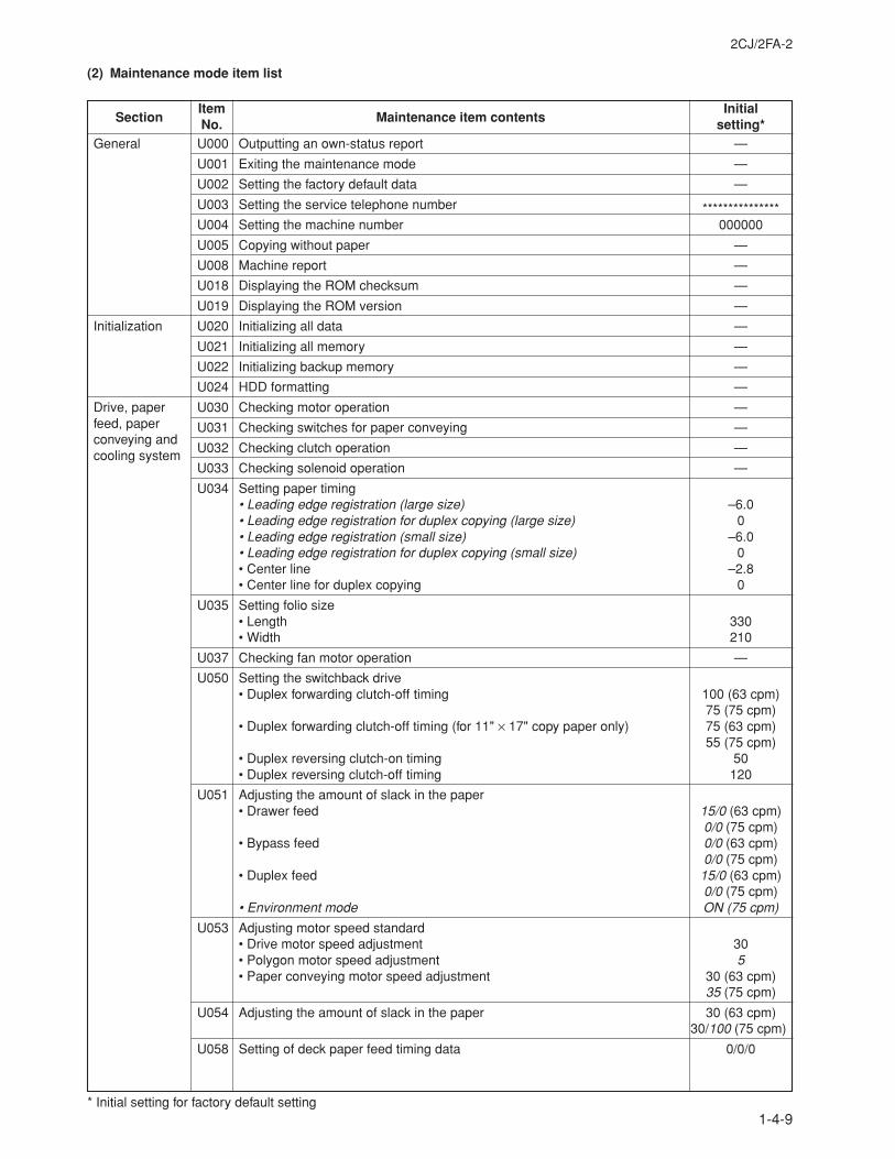
2CJ/2FA-2
1-4-9
General
Initialization
Drive, paperfeed, paperconveying andcooling system
U000 Outputting an own-status report —
U001 Exiting the maintenance mode —
U002 Setting the factory default data —
U003 Setting the service telephone number ***************U004 Setting the machine number 000000
U005 Copying without paper —
U008 Machine report —
U018 Displaying the ROM checksum —
U019 Displaying the ROM version —
U020 Initializing all data —
U021 Initializing all memory —
U022 Initializing backup memory —
U024 HDD formatting —
U030 Checking motor operation —
U031 Checking switches for paper conveying —
U032 Checking clutch operation —
U033 Checking solenoid operation —
U034 Setting paper timing• Leading edge registration (large size) –6.0• Leading edge registration for duplex copying (large size) 0• Leading edge registration (small size) –6.0• Leading edge registration for duplex copying (small size) 0• Center line –2.8• Center line for duplex copying 0
U035 Setting folio size• Length 330• Width 210
U037 Checking fan motor operation —
U050 Setting the switchback drive• Duplex forwarding clutch-off timing 100 (63 cpm)
75 (75 cpm)• Duplex forwarding clutch-off timing (for 11" × 17" copy paper only) 75 (63 cpm)
55 (75 cpm)• Duplex reversing clutch-on timing 50• Duplex reversing clutch-off timing 120
U051 Adjusting the amount of slack in the paper• Drawer feed 15/0 (63 cpm)
0/0 (75 cpm)• Bypass feed 0/0 (63 cpm)
0/0 (75 cpm)• Duplex feed 15/0 (63 cpm)
0/0 (75 cpm)• Environment mode ON (75 cpm)
U053 Adjusting motor speed standard• Drive motor speed adjustment 30• Polygon motor speed adjustment 5• Paper conveying motor speed adjustment 30 (63 cpm)
35 (75 cpm)
U054 Adjusting the amount of slack in the paper 30 (63 cpm)30/100 (75 cpm)
U058 Setting of deck paper feed timing data 0/0/0
* Initial setting for factory default setting
SectionItem
Maintenance item contentsInitial
No. setting*
(2) Maintenance mode item list
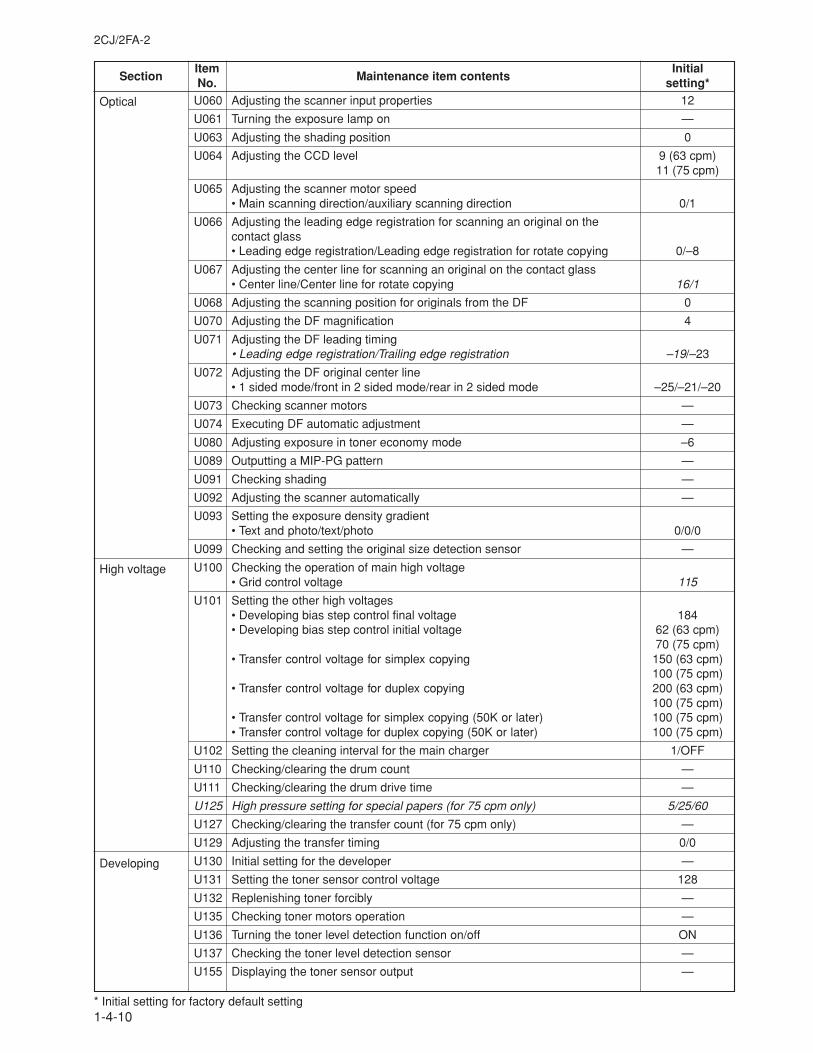
SectionItem
Maintenance item contentsInitial
No. setting*
2CJ/2FA-2
1-4-10
Optical
High voltage
Developing
U060 Adjusting the scanner input properties 12
U061 Turning the exposure lamp on —
U063 Adjusting the shading position 0
U064 Adjusting the CCD level 9 (63 cpm)11 (75 cpm)
U065 Adjusting the scanner motor speed• Main scanning direction/auxiliary scanning direction 0/1
U066 Adjusting the leading edge registration for scanning an original on thecontact glass• Leading edge registration/Leading edge registration for rotate copying 0/–8
U067 Adjusting the center line for scanning an original on the contact glass• Center line/Center line for rotate copying 16/1
U068 Adjusting the scanning position for originals from the DF 0
U070 Adjusting the DF magnification 4
U071 Adjusting the DF leading timing• Leading edge registration/Trailing edge registration –19/–23
U072 Adjusting the DF original center line• 1 sided mode/front in 2 sided mode/rear in 2 sided mode –25/–21/–20
U073 Checking scanner motors —
U074 Executing DF automatic adjustment —
U080 Adjusting exposure in toner economy mode –6
U089 Outputting a MIP-PG pattern —
U091 Checking shading —
U092 Adjusting the scanner automatically —
U093 Setting the exposure density gradient• Text and photo/text/photo 0/0/0
U099 Checking and setting the original size detection sensor —
U100 Checking the operation of main high voltage• Grid control voltage 115
U101 Setting the other high voltages• Developing bias step control final voltage 184• Developing bias step control initial voltage 62 (63 cpm)
70 (75 cpm)• Transfer control voltage for simplex copying 150 (63 cpm)
100 (75 cpm)• Transfer control voltage for duplex copying 200 (63 cpm)
100 (75 cpm)• Transfer control voltage for simplex copying (50K or later) 100 (75 cpm)• Transfer control voltage for duplex copying (50K or later) 100 (75 cpm)
U102 Setting the cleaning interval for the main charger 1/OFF
U110 Checking/clearing the drum count —
U111 Checking/clearing the drum drive time —
U125 High pressure setting for special papers (for 75 cpm only) 5/25/60
U127 Checking/clearing the transfer count (for 75 cpm only) —
U129 Adjusting the transfer timing 0/0
U130 Initial setting for the developer —
U131 Setting the toner sensor control voltage 128
U132 Replenishing toner forcibly —
U135 Checking toner motors operation —
U136 Turning the toner level detection function on/off ON
U137 Checking the toner level detection sensor —
U155 Displaying the toner sensor output —
* Initial setting for factory default setting
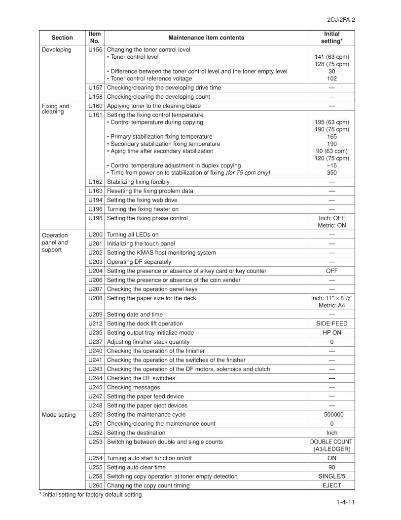
2CJ/2FA-2
1-4-11
SectionItem
Maintenance item contentsInitial
No. setting*U156 Changing the toner control level
• Toner control level 141 (63 cpm)128 (75 cpm)
• Difference between the toner control level and the toner empty level 30• Toner control reference voltage 102
U157 Checking/clearing the developing drive time —
U158 Checking/clearing the developing count —
U160 Applying toner to the cleaning blade —
U161 Setting the fixing control temperature• Control temperature during copying 195 (63 cpm)
190 (75 cpm)• Primary stabilization fixing temperature 165• Secondary stabilization fixing temperature 190• Aging time after secondary stabilization 90 (63 cpm)
120 (75 cpm)• Control temperature adjustment in duplex copying –15• Time from power on to stabilization of fixing (for 75 cpm only) 350
U162 Stabilizing fixing forcibly —
U163 Resetting the fixing problem data —
U194 Setting the fixing web drive —
U196 Turning the fixing heater on —
U198 Setting the fixing phase control Inch: OFFMetric: ON
U200 Turning all LEDs on —
U201 Initializing the touch panel —
U202 Setting the KMAS host monitoring system —
U203 Operating DF separately —
U204 Setting the presence or absence of a key card or key counter OFF
U206 Setting the presence or absence of the coin vender —
U207 Checking the operation panel keys —
U208 Setting the paper size for the deck Inch: 11" × 81/2"Metric: A4
U209 Setting date and time —
U212 Setting the deck lift operation SIDE FEED
U235 Setting output tray initialize mode HP ON
U237 Adjusting finisher stack quantity 0
U240 Checking the operation of the finisher —
U241 Checking the operation of the switches of the finisher —
U243 Checking the operation of the DF motors, solenoids and clutch —
U244 Checking the DF switches —
U245 Checking messages —
U247 Setting the paper feed device —
U248 Setting the paper eject devices —
U250 Setting the maintenance cycle 500000
U251 Checking/clearing the maintenance count 0
U252 Setting the destination Inch
U253 Switching between double and single counts DOUBLE COUNT(A3/LEDGER)
U254 Turning auto start function on/off ON
U255 Setting auto clear time 90
U258 Switching copy operation at toner empty detection SINGLE/5
U260 Changing the copy count timing EJECT
* Initial setting for factory default setting
Developing
Fixing andcleaning
Operationpanel andsupport
Mode setting
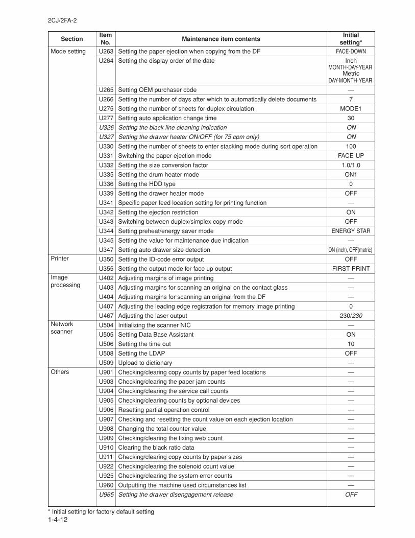
SectionItem
Maintenance item contentsInitial
No. setting*
2CJ/2FA-2
1-4-12
U263 Setting the paper ejection when copying from the DF FACE-DOWN
U264 Setting the display order of the date InchMONTH-DAY-YEAR
MetricDAY-MONTH-YEAR
U265 Setting OEM purchaser code —
U266 Setting the number of days after which to automatically delete documents 7
U275 Setting the number of sheets for duplex circulation MODE1
U277 Setting auto application change time 30
U326 Setting the black line cleaning indication ON
U327 Setting the drawer heater ON/OFF (for 75 cpm only) ON
U330 Setting the number of sheets to enter stacking mode during sort operation 100
U331 Switching the paper ejection mode FACE UP
U332 Setting the size conversion factor 1.0/1.0
U335 Setting the drum heater mode ON1
U336 Setting the HDD type 0
U339 Setting the drawer heater mode OFF
U341 Specific paper feed location setting for printing function —
U342 Setting the ejection restriction ON
U343 Switching between duplex/simplex copy mode OFF
U344 Setting preheat/energy saver mode ENERGY STAR
U345 Setting the value for maintenance due indication —
U347 Setting auto drawer size detection ON (inch), OFF(metric)
U350 Setting the ID-code error output OFF
U355 Setting the output mode for face up output FIRST PRINT
U402 Adjusting margins of image printing —
U403 Adjusting margins for scanning an original on the contact glass —
U404 Adjusting margins for scanning an original from the DF —
U407 Adjusting the leading edge registration for memory image printing 0
U467 Adjusting the laser output 230/230
U504 Initializing the scanner NIC —
U505 Setting Data Base Assistant ON
U506 Setting the time out 10
U508 Setting the LDAP OFF
U509 Upload to dictionary —
U901 Checking/clearing copy counts by paper feed locations —
U903 Checking/clearing the paper jam counts —
U904 Checking/clearing the service call counts —
U905 Checking/clearing counts by optional devices —
U906 Resetting partial operation control —
U907 Checking and resetting the count value on each ejection location —
U908 Changing the total counter value —
U909 Checking/clearing the fixing web count —
U910 Clearing the black ratio data —
U911 Checking/clearing copy counts by paper sizes —
U922 Checking/clearing the solenoid count value —
U925 Checking/clearing the system error counts —
U960 Outputting the machine used circumstances list —
U965 Setting the drawer disengagement release OFF
* Initial setting for factory default setting
Mode setting
Printer
Imageprocessing
Networkscanner
Others
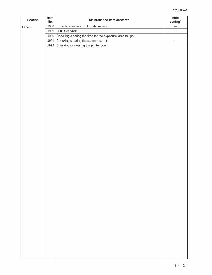
2CJ/2FA-2
1-4-13
SectionItem
Maintenance item contentsInitial
No. setting*U988 ID-code scanner count mode setting —
U989 HDD Scandisk —
U990 Checking/clearing the time for the exposure lamp to light —
U991 Checking/clearing the scanner count —
U992 Checking or clearing the printer count
Others
1-4-12-1

2CJ/2FA-2
1-4-14
This page is intentionally left blank.
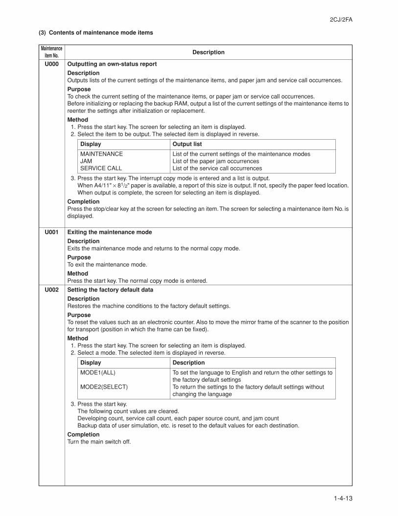
1-4-13
2CJ/2FA
U000 Outputting an own-status report
DescriptionOutputs lists of the current settings of the maintenance items, and paper jam and service call occurrences.
PurposeTo check the current setting of the maintenance items, or paper jam or service call occurrences.Before initializing or replacing the backup RAM, output a list of the current settings of the maintenance items toreenter the settings after initialization or replacement.
Method1. Press the start key. The screen for selecting an item is displayed.2. Select the item to be output. The selected item is displayed in reverse.
Display Output list
MAINTENANCE List of the current settings of the maintenance modesJAM List of the paper jam occurrencesSERVICE CALL List of the service call occurrences
3. Press the start key. The interrupt copy mode is entered and a list is output.When A4/11" × 81/2" paper is available, a report of this size is output. If not, specify the paper feed location.When output is complete, the screen for selecting an item is displayed.
CompletionPress the stop/clear key at the screen for selecting an item. The screen for selecting a maintenance item No. isdisplayed.
U001 Exiting the maintenance mode
DescriptionExits the maintenance mode and returns to the normal copy mode.
PurposeTo exit the maintenance mode.
MethodPress the start key. The normal copy mode is entered.
U002 Setting the factory default data
DescriptionRestores the machine conditions to the factory default settings.
PurposeTo reset the values such as an electronic counter. Also to move the mirror frame of the scanner to the positionfor transport (position in which the frame can be fixed).
Method1. Press the start key. The screen for selecting an item is displayed.2. Select a mode. The selected item is displayed in reverse.
Display Description
MODE1(ALL) To set the language to English and return the other settings tothe factory default settings
MODE2(SELECT) To return the settings to the factory default settings withoutchanging the language
3. Press the start key.The following count values are cleared.Developing count, service call count, each paper source count, and jam countBackup data of user simulation, etc. is reset to the default values for each destination.
CompletionTurn the main switch off.
(3) Contents of maintenance mode items
MaintenanceDescriptionitem No.
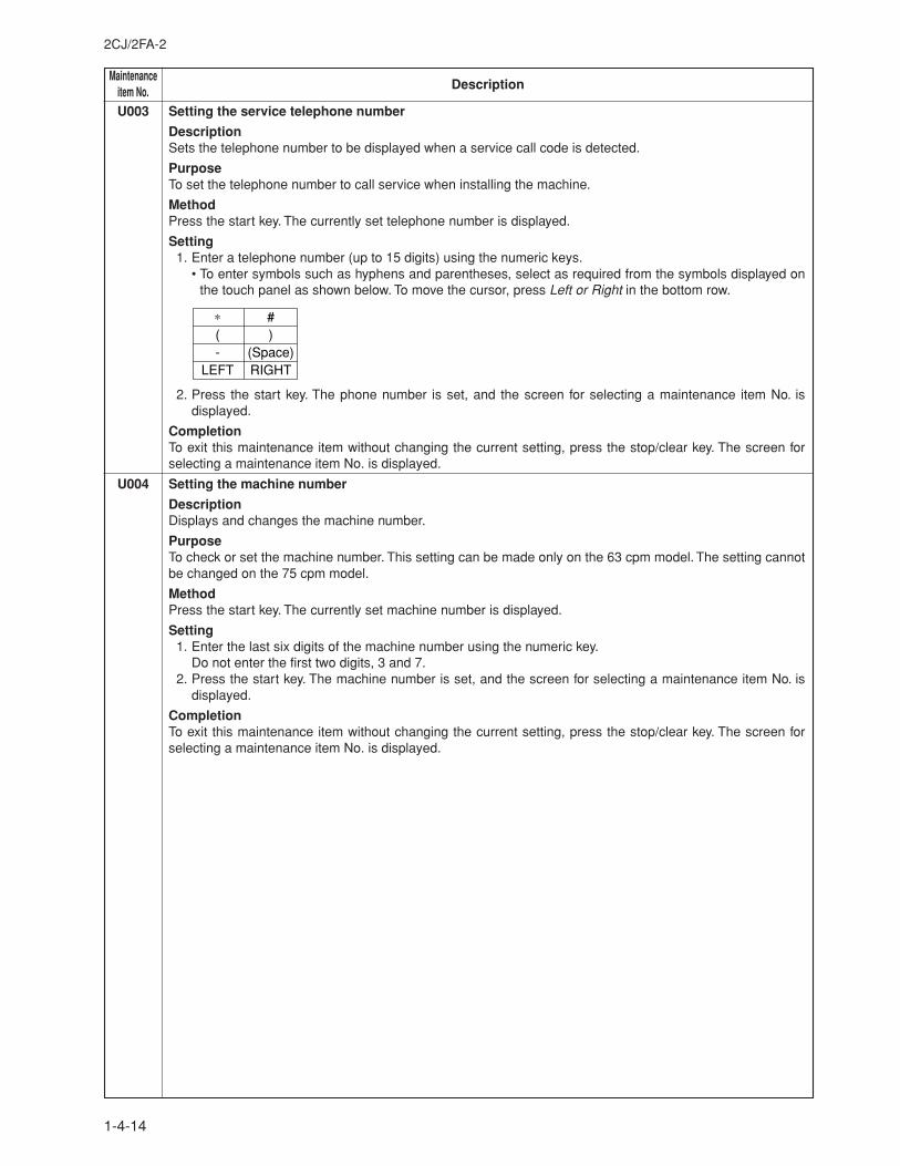
MaintenanceDescriptionitem No.
2CJ/2FA-2
1-4-14
U003 Setting the service telephone number
DescriptionSets the telephone number to be displayed when a service call code is detected.
PurposeTo set the telephone number to call service when installing the machine.
MethodPress the start key. The currently set telephone number is displayed.
Setting1. Enter a telephone number (up to 15 digits) using the numeric keys.
• To enter symbols such as hyphens and parentheses, select as required from the symbols displayed onthe touch panel as shown below. To move the cursor, press Left or Right in the bottom row.
∗(-
LEFT
#)
(Space)RIGHT
2. Press the start key. The phone number is set, and the screen for selecting a maintenance item No. isdisplayed.
CompletionTo exit this maintenance item without changing the current setting, press the stop/clear key. The screen forselecting a maintenance item No. is displayed.
U004 Setting the machine number
DescriptionDisplays and changes the machine number.
PurposeTo check or set the machine number. This setting can be made only on the 63 cpm model. The setting cannotbe changed on the 75 cpm model.
MethodPress the start key. The currently set machine number is displayed.
Setting1. Enter the last six digits of the machine number using the numeric key.
Do not enter the first two digits, 3 and 7.2. Press the start key. The machine number is set, and the screen for selecting a maintenance item No. is
displayed.
CompletionTo exit this maintenance item without changing the current setting, press the stop/clear key. The screen forselecting a maintenance item No. is displayed.
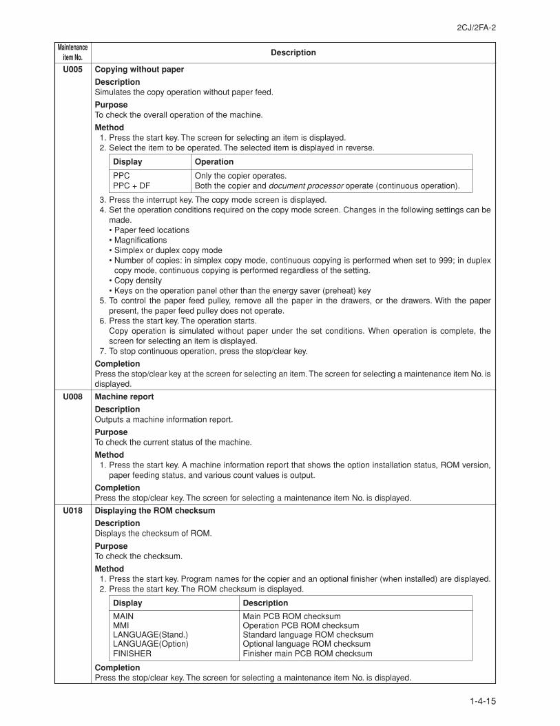
2CJ/2FA-2
1-4-15
MaintenanceDescriptionitem No.
U005 Copying without paper
DescriptionSimulates the copy operation without paper feed.
PurposeTo check the overall operation of the machine.
Method1. Press the start key. The screen for selecting an item is displayed.2. Select the item to be operated. The selected item is displayed in reverse.
Display Operation
PPC Only the copier operates.PPC + DF Both the copier and document processor operate (continuous operation).
3. Press the interrupt key. The copy mode screen is displayed.4. Set the operation conditions required on the copy mode screen. Changes in the following settings can be
made.• Paper feed locations• Magnifications• Simplex or duplex copy mode• Number of copies: in simplex copy mode, continuous copying is performed when set to 999; in duplex
copy mode, continuous copying is performed regardless of the setting.• Copy density• Keys on the operation panel other than the energy saver (preheat) key
5. To control the paper feed pulley, remove all the paper in the drawers, or the drawers. With the paperpresent, the paper feed pulley does not operate.
6. Press the start key. The operation starts.Copy operation is simulated without paper under the set conditions. When operation is complete, thescreen for selecting an item is displayed.
7. To stop continuous operation, press the stop/clear key.
CompletionPress the stop/clear key at the screen for selecting an item. The screen for selecting a maintenance item No. isdisplayed.
U008 Machine report
DescriptionOutputs a machine information report.
PurposeTo check the current status of the machine.
Method1. Press the start key. A machine information report that shows the option installation status, ROM version,
paper feeding status, and various count values is output.
CompletionPress the stop/clear key. The screen for selecting a maintenance item No. is displayed.
U018 Displaying the ROM checksum
DescriptionDisplays the checksum of ROM.
PurposeTo check the checksum.
Method1. Press the start key. Program names for the copier and an optional finisher (when installed) are displayed.2. Press the start key. The ROM checksum is displayed.
Display Description
MAIN Main PCB ROM checksumMMI Operation PCB ROM checksumLANGUAGE(Stand.) Standard language ROM checksumLANGUAGE(Option) Optional language ROM checksumFINISHER Finisher main PCB ROM checksum
CompletionPress the stop/clear key. The screen for selecting a maintenance item No. is displayed.
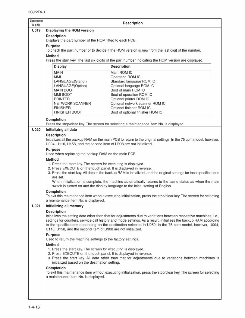
MaintenanceDescriptionitem No.
2CJ/2FA-1
1-4-16
U019 Displaying the ROM version
DescriptionDisplays the part number of the ROM fitted to each PCB.
PurposeTo check the part number or to decide if the ROM version is new from the last digit of the number.
MethodPress the start key. The last six digits of the part number indicating the ROM version are displayed.
Display Description
MAIN Main ROM ICMMI Operation ROM ICLANGUAGE(Stand.) Standard language ROM ICLANGUAGE(Option) Optional language ROM ICMAIN BOOT Boot of main ROM ICMMI BOOT Boot of operation ROM ICPRINTER Optional printer ROM ICNETWORK SCANNER Optional network scanner ROM ICFINISHER Optional finisher ROM ICFINISHER BOOT Boot of optional finisher ROM IC
CompletionPress the stop/clear key. The screen for selecting a maintenance item No. is displayed.
U020 Initializing all data
DescriptionInitializes all the backup RAM on the main PCB to return to the original settings. In the 75 cpm model, however,U004, U110, U158, and the second item of U908 are not initialized.
PurposeUsed when replacing the backup RAM on the main PCB.
Method1. Press the start key. The screen for executing is displayed.2. Press EXECUTE on the touch panel. It is displayed in reverse.3. Press the start key. All data in the backup RAM is initialized, and the original settings for inch specifications
are set.When initialization is complete, the machine automatically returns to the same status as when the mainswitch is turned on and the display language to the initial setting of English.
CompletionTo exit this maintenance item without executing initialization, press the stop/clear key. The screen for selectinga maintenance item No. is displayed.
U021 Initializing all memory
DescriptionInitializes the setting data other than that for adjustments due to variations between respective machines, i.e.,settings for counters, service call history and mode settings. As a result, initializes the backup RAM accordingto the specifications depending on the destination selected in U252. In the 75 cpm model, however, U004,U110, U158, and the second item of U908 are not initialized.
PurposeUsed to return the machine settings to the factory settings.
Method1. Press the start key. The screen for executing is displayed.2. Press EXECUTE on the touch panel. It is displayed in reverse.3. Press the start key. All data other than that for adjustments due to variations between machines is
initialized based on the destination setting.
CompletionTo exit this maintenance item without executing initialization, press the stop/clear key. The screen for selectinga maintenance item No. is displayed.
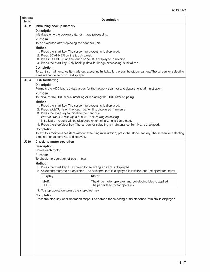
2CJ/2FA-2
1-4-17
MaintenanceDescriptionitem No.
U022 Initializing backup memory
DescriptionInitializes only the backup data for image processing.
PurposeTo be executed after replacing the scanner unit.
Method1. Press the start key. The screen for executing is displayed.2. Press SCANNER on the touch panel.3. Press EXECUTE on the touch panel. It is displayed in reverse.4. Press the start key. Only backup data for image processing is initialized.
CompletionTo exit this maintenance item without executing initialization, press the stop/clear key. The screen for selectinga maintenance item No. is displayed.
U024 HDD formatting
DescriptionFormats the HDD backup data areas for the network scanner and department administration.
PurposeTo initialize the HDD when installing or replacing the HDD after shipping.
Method1. Press the start key. The screen for executing is displayed.2. Press EXECUTE on the touch panel. It is displayed in reverse.3. Press the start key to initialize the hard disk.
Format status is displayed in 0 to 100% during initializing.Initialization results will be displayed when initializing is completed.
4. Press the stop/clear key. The screen for selecting a maintenance item No. is displayed.
CompletionTo exit this maintenance item without executing initialization, press the stop/clear key. The screen for selectinga maintenance item No. is displayed.
U030 Checking motor operation
DescriptionDrives each motor.
PurposeTo check the operation of each motor.
Method1. Press the start key. The screen for selecting an item is displayed.2. Select the motor to be operated. The selected item is displayed in reverse and the operation starts.
Display Motor
MAIN The drive motor operates and developing bias is applied.FEED The paper feed motor operates.
3. To stop operation, press the stop/clear key.
CompletionPress the stop key after operation stops. The screen for selecting a maintenance item No. is displayed.
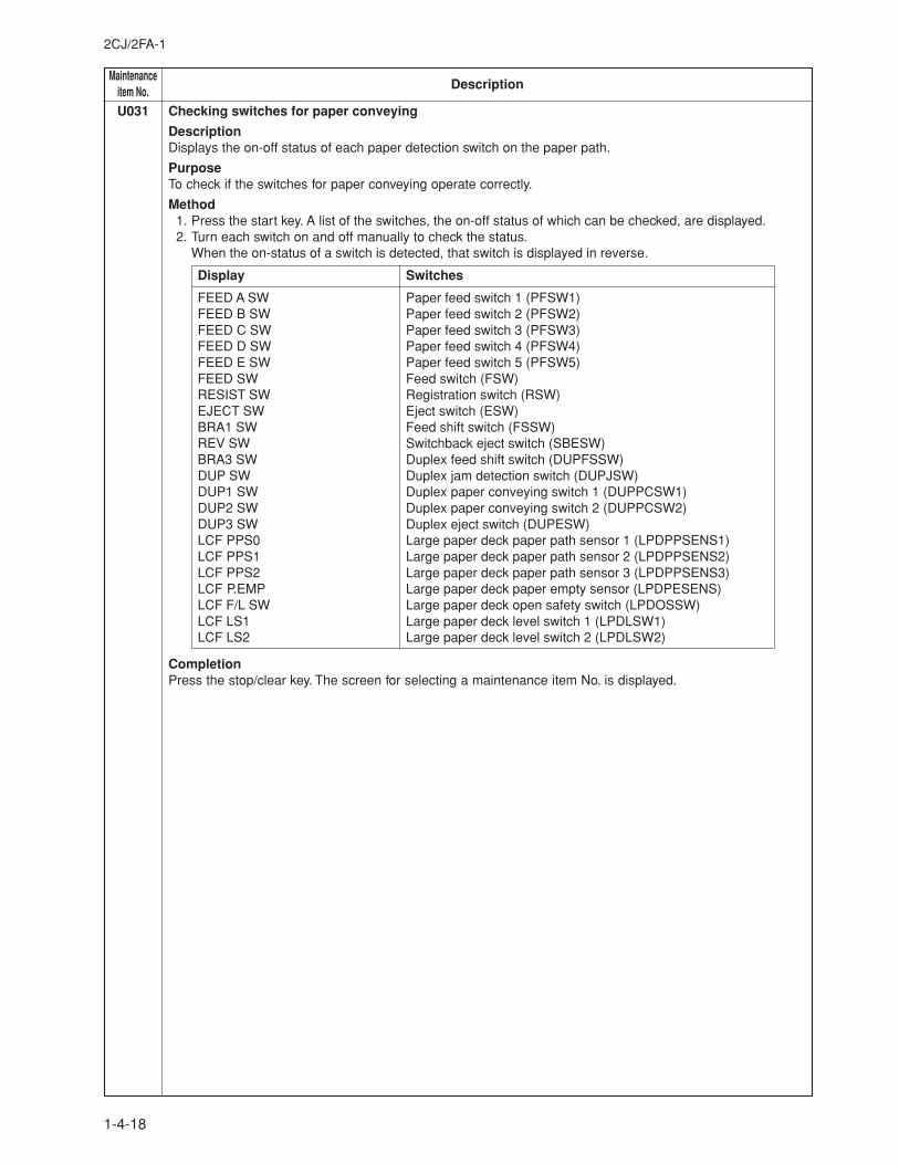
MaintenanceDescriptionitem No.
2CJ/2FA-1
1-4-18
U031 Checking switches for paper conveying
DescriptionDisplays the on-off status of each paper detection switch on the paper path.
PurposeTo check if the switches for paper conveying operate correctly.
Method1. Press the start key. A list of the switches, the on-off status of which can be checked, are displayed.2. Turn each switch on and off manually to check the status.
When the on-status of a switch is detected, that switch is displayed in reverse.
Display Switches
FEED A SW Paper feed switch 1 (PFSW1)FEED B SW Paper feed switch 2 (PFSW2)FEED C SW Paper feed switch 3 (PFSW3)FEED D SW Paper feed switch 4 (PFSW4)FEED E SW Paper feed switch 5 (PFSW5)FEED SW Feed switch (FSW)RESIST SW Registration switch (RSW)EJECT SW Eject switch (ESW)BRA1 SW Feed shift switch (FSSW)REV SW Switchback eject switch (SBESW)BRA3 SW Duplex feed shift switch (DUPFSSW)DUP SW Duplex jam detection switch (DUPJSW)DUP1 SW Duplex paper conveying switch 1 (DUPPCSW1)DUP2 SW Duplex paper conveying switch 2 (DUPPCSW2)DUP3 SW Duplex eject switch (DUPESW)LCF PPS0 Large paper deck paper path sensor 1 (LPDPPSENS1)LCF PPS1 Large paper deck paper path sensor 2 (LPDPPSENS2)LCF PPS2 Large paper deck paper path sensor 3 (LPDPPSENS3)LCF P.EMP Large paper deck paper empty sensor (LPDPESENS)LCF F/L SW Large paper deck open safety switch (LPDOSSW)LCF LS1 Large paper deck level switch 1 (LPDLSW1)LCF LS2 Large paper deck level switch 2 (LPDLSW2)
CompletionPress the stop/clear key. The screen for selecting a maintenance item No. is displayed.
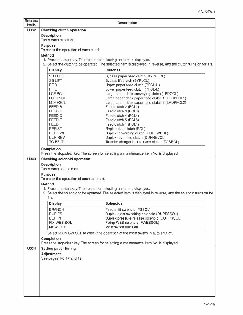
2CJ/2FA-1
1-4-19
MaintenanceDescriptionitem No.
U032 Checking clutch operation
DescriptionTurns each clutch on.
PurposeTo check the operation of each clutch.
Method1. Press the start key. The screen for selecting an item is displayed.2. Select the clutch to be operated. The selected item is displayed in reverse, and the clutch turns on for 1 s.
Display Clutches
SB FEED Bypass paper feed clutch (BYPPFCL)SB LIFT Bypass lift clutch (BYPLCL)PF D Upper paper feed clutch (PFCL-U)PF E Lower paper feed clutch (PFCL-L)LCF BCL Large paper deck conveying clutch (LPDCCL)LCF P1CL Large paper deck paper feed clutch 1 (LPDPFCL1)LCF P2CL Large paper deck paper feed clutch 2 (LPDPFCL2)FEED B Feed clutch 2 (FCL2)FEED C Feed clutch 3 (FCL3)FEED D Feed clutch 4 (FCL4)FEED E Feed clutch 5 (FCL5)FEED Feed clutch 1 (FCL1)RESIST Registration clutch (RCL)DUP FWD Duplex forwarding clutch (DUPFWDCL)DUP REV Duplex reversing clutch (DUPREVCL)TC BELT Transfer charger belt release clutch (TCBRCL)
CompletionPress the stop/clear key. The screen for selecting a maintenance item No. is displayed.
U033 Checking solenoid operation
DescriptionTurns each solenoid on.
PurposeTo check the operation of each solenoid.
Method1. Press the start key. The screen for selecting an item is displayed.2. Select the solenoid to be operated. The selected item is displayed in reverse, and the solenoid turns on for
1 s.
Display Solenoids
BRANCH Feed shift solenoid (FSSOL)DUP FS Duplex eject switching solenoid (DUPESSOL)DUP PR Duplex pressure release solenoid (DUPPRSOL)FIX WEB SOL Fixing WEB solenoid (FWEBSOL)MSW OFF Main switch turns on
Select MAIN SW SOL to check the operation of the main switch in auto shut off.
CompletionPress the stop/clear key. The screen for selecting a maintenance item No. is displayed.
U034 Setting paper timing
AdjustmentSee pages 1-6-17 and 19.
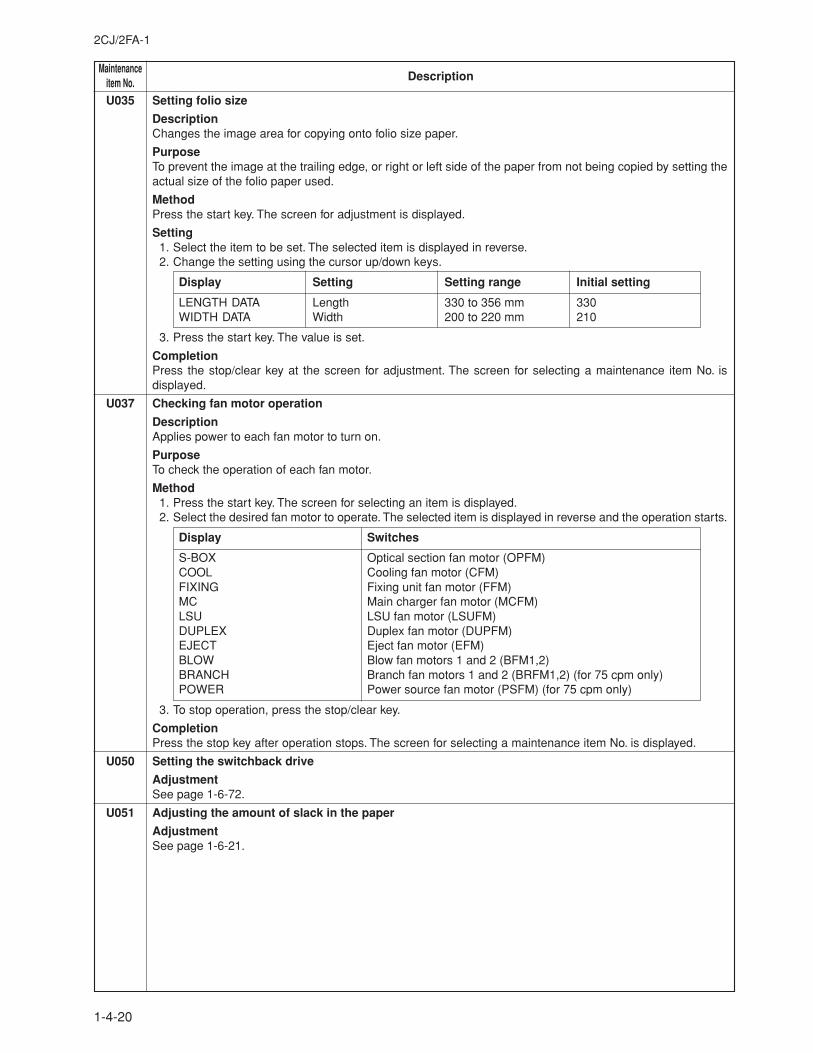
MaintenanceDescriptionitem No.
2CJ/2FA-1
1-4-20
U035 Setting folio size
DescriptionChanges the image area for copying onto folio size paper.
PurposeTo prevent the image at the trailing edge, or right or left side of the paper from not being copied by setting theactual size of the folio paper used.
MethodPress the start key. The screen for adjustment is displayed.
Setting1. Select the item to be set. The selected item is displayed in reverse.2. Change the setting using the cursor up/down keys.
Display Setting Setting range Initial setting
LENGTH DATA Length 330 to 356 mm 330WIDTH DATA Width 200 to 220 mm 210
3. Press the start key. The value is set.
CompletionPress the stop/clear key at the screen for adjustment. The screen for selecting a maintenance item No. isdisplayed.
U037 Checking fan motor operation
DescriptionApplies power to each fan motor to turn on.
PurposeTo check the operation of each fan motor.
Method1. Press the start key. The screen for selecting an item is displayed.2. Select the desired fan motor to operate. The selected item is displayed in reverse and the operation starts.
Display Switches
S-BOX Optical section fan motor (OPFM)COOL Cooling fan motor (CFM)FIXING Fixing unit fan motor (FFM)MC Main charger fan motor (MCFM)LSU LSU fan motor (LSUFM)DUPLEX Duplex fan motor (DUPFM)EJECT Eject fan motor (EFM)BLOW Blow fan motors 1 and 2 (BFM1,2)BRANCH Branch fan motors 1 and 2 (BRFM1,2) (for 75 cpm only)POWER Power source fan motor (PSFM) (for 75 cpm only)
3. To stop operation, press the stop/clear key.
CompletionPress the stop key after operation stops. The screen for selecting a maintenance item No. is displayed.
U050 Setting the switchback drive
AdjustmentSee page 1-6-72.
U051 Adjusting the amount of slack in the paper
AdjustmentSee page 1-6-21.
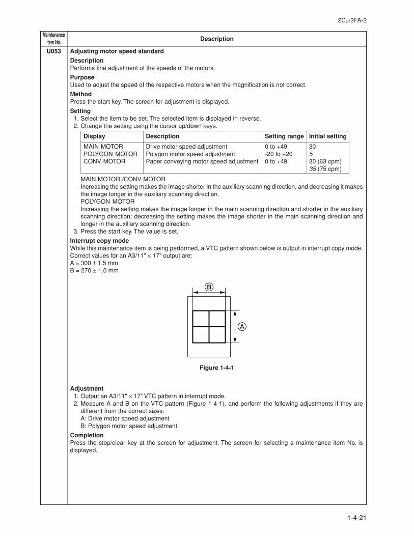
2CJ/2FA-2
1-4-21
MaintenanceDescriptionitem No.
U053 Adjusting motor speed standard
DescriptionPerforms fine adjustment of the speeds of the motors.
PurposeUsed to adjust the speed of the respective motors when the magnification is not correct.
MethodPress the start key. The screen for adjustment is displayed.
Setting1. Select the item to be set. The selected item is displayed in reverse.2. Change the setting using the cursor up/down keys.
Display Description Setting range Initial setting
MAIN MOTOR Drive motor speed adjustment 0 to +49 30POLYGON MOTOR Polygon motor speed adjustment -20 to +20 5CONV MOTOR Paper conveying motor speed adjustment 0 to +49 30 (63 cpm)
35 (75 cpm)
MAIN MOTOR /CONV MOTORIncreasing the setting makes the image shorter in the auxiliary scanning direction, and decreasing it makesthe image longer in the auxiliary scanning direction.POLYGON MOTORIncreasing the setting makes the image longer in the main scanning direction and shorter in the auxiliaryscanning direction; decreasing the setting makes the image shorter in the main scanning direction andlonger in the auxiliary scanning direction.
3. Press the start key. The value is set.
Interrupt copy modeWhile this maintenance item is being performed, a VTC pattern shown below is output in interrupt copy mode.Correct values for an A3/11" × 17" output are:A = 300 ± 1.5 mmB = 270 ± 1.0 mm
Figure 1-4-1
Adjustment1. Output an A3/11" × 17" VTC pattern in interrupt mode.2. Measure A and B on the VTC pattern (Figure 1-4-1), and perform the following adjustments if they are
different from the correct sizes:A: Drive motor speed adjustmentB: Polygon motor speed adjustment
CompletionPress the stop/clear key at the screen for adjustment. The screen for selecting a maintenance item No. isdisplayed.
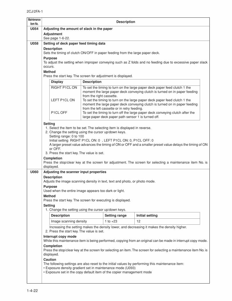
MaintenanceDescriptionitem No.
2CJ/2FA-1
1-4-22
U054 Adjusting the amount of slack in the paper
AdjustmentSee page 1-6-22.
U058 Setting of deck paper feed timing data
DescriptionSets the timing of clutch ON/OFF in paper feeding from the large paper deck.
PurposeTo adjust the setting when improper conveying such as Z folds and no feeding due to excessive paper slackoccurs.
MethodPress the start key. The screen for adjustment is displayed.
Display Description
RIGHT P1CL ON To set the timing to turn on the large paper deck paper feed clutch 1 themoment the large paper deck conveying clutch is turned on in paper feedingfrom the right cassette.
LEFT P1CL ON To set the timing to turn on the large paper deck paper feed clutch 1 themoment the large paper deck conveying clutch is turned on in paper feedingfrom the left cassette or in retry feeding.
P1CL OFF To set the timing to turn off the large paper deck conveying clutch after thelarge paper deck paper path sensor 1 is turned off.
Setting1. Select the item to be set. The selecting item is displayed in reverse.2. Change the setting using the cursor up/down keys.
Setting range: 0 to 100Initial setting RIGHT P1CL ON: 0 , LEFT P1CL ON: 0, P1CL OFF: 0A larger preset value advances the timing of ON or OFF and a smaller preset value delays the timing of ONor OFF.
3. Press the start key. The value is set.
CompletionPress the stop/clear key at the screen for adjustment. The screen for selecting a maintenance item No. isdisplayed.
U060 Adjusting the scanner input properties
DescriptionAdjusts the image scanning density in text, text and photo, or photo mode.
PurposeUsed when the entire image appears too dark or light.
MethodPress the start key. The screen for executing is displayed.
Setting1. Change the setting using the cursor up/down keys.
Description Setting range Initial setting
Image scanning density 1 to +23 12
Increasing the setting makes the density lower, and decreasing it makes the density higher.2. Press the start key. The value is set.
Interrupt copy modeWhile this maintenance item is being performed, copying from an original can be made in interrupt copy mode.
CompletionPress the stop/clear key at the screen for selecting an item. The screen for selecting a maintenance item No. isdisplayed.
CautionThe following settings are also reset to the initial values by performing this maintenance item:• Exposure density gradient set in maintenance mode (U093)• Exposure set in the copy default item of the copier management mode
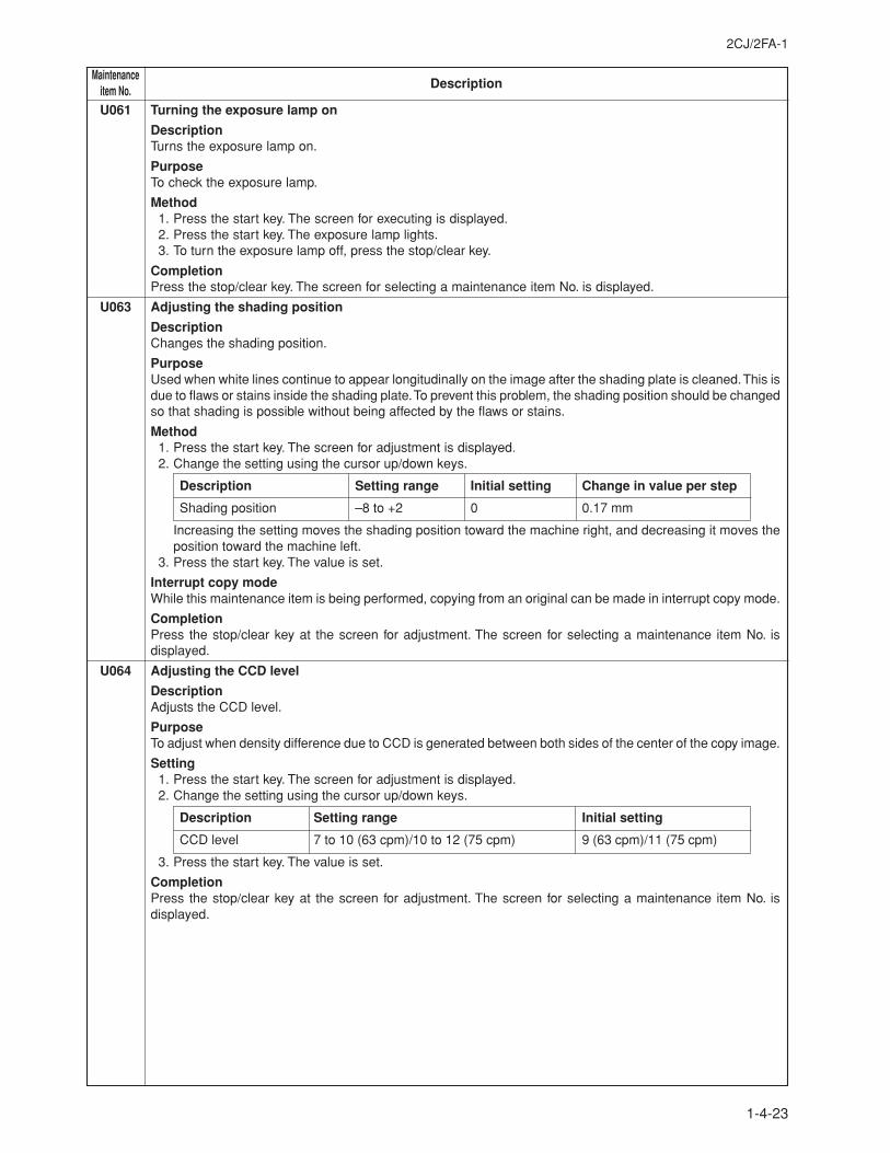
2CJ/2FA-1
1-4-23
MaintenanceDescriptionitem No.
U061 Turning the exposure lamp on
DescriptionTurns the exposure lamp on.
PurposeTo check the exposure lamp.
Method1. Press the start key. The screen for executing is displayed.2. Press the start key. The exposure lamp lights.3. To turn the exposure lamp off, press the stop/clear key.
CompletionPress the stop/clear key. The screen for selecting a maintenance item No. is displayed.
U063 Adjusting the shading position
DescriptionChanges the shading position.
PurposeUsed when white lines continue to appear longitudinally on the image after the shading plate is cleaned. This isdue to flaws or stains inside the shading plate. To prevent this problem, the shading position should be changedso that shading is possible without being affected by the flaws or stains.
Method1. Press the start key. The screen for adjustment is displayed.2. Change the setting using the cursor up/down keys.
Description Setting range Initial setting Change in value per step
Shading position –8 to +2 0 0.17 mm
Increasing the setting moves the shading position toward the machine right, and decreasing it moves theposition toward the machine left.
3. Press the start key. The value is set.
Interrupt copy modeWhile this maintenance item is being performed, copying from an original can be made in interrupt copy mode.
CompletionPress the stop/clear key at the screen for adjustment. The screen for selecting a maintenance item No. isdisplayed.
U064 Adjusting the CCD level
DescriptionAdjusts the CCD level.
PurposeTo adjust when density difference due to CCD is generated between both sides of the center of the copy image.
Setting1. Press the start key. The screen for adjustment is displayed.2. Change the setting using the cursor up/down keys.
Description Setting range Initial setting
CCD level 7 to 10 (63 cpm)/10 to 12 (75 cpm) 9 (63 cpm)/11 (75 cpm)
3. Press the start key. The value is set.
CompletionPress the stop/clear key at the screen for adjustment. The screen for selecting a maintenance item No. isdisplayed.
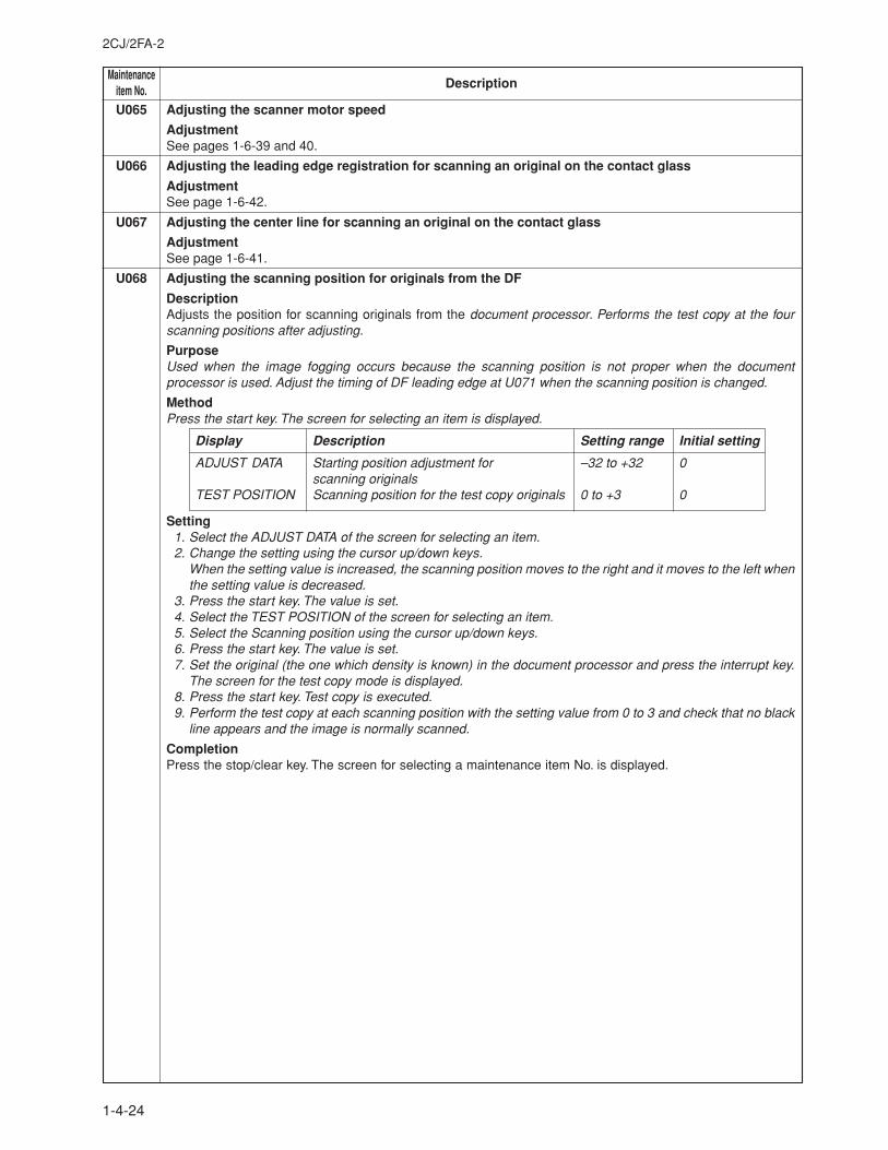
MaintenanceDescriptionitem No.
2CJ/2FA-2
1-4-24
U065 Adjusting the scanner motor speed
AdjustmentSee pages 1-6-39 and 40.
U066 Adjusting the leading edge registration for scanning an original on the contact glass
AdjustmentSee page 1-6-42.
U067 Adjusting the center line for scanning an original on the contact glass
AdjustmentSee page 1-6-41.
U068 Adjusting the scanning position for originals from the DF
DescriptionAdjusts the position for scanning originals from the document processor. Performs the test copy at the fourscanning positions after adjusting.
PurposeUsed when the image fogging occurs because the scanning position is not proper when the documentprocessor is used. Adjust the timing of DF leading edge at U071 when the scanning position is changed.
MethodPress the start key. The screen for selecting an item is displayed.
Display Description Setting range Initial setting
ADJUST DATA Starting position adjustment for –32 to +32 0scanning originals
TEST POSITION Scanning position for the test copy originals 0 to +3 0
Setting1. Select the ADJUST DATA of the screen for selecting an item.2. Change the setting using the cursor up/down keys.
When the setting value is increased, the scanning position moves to the right and it moves to the left whenthe setting value is decreased.
3. Press the start key. The value is set.4. Select the TEST POSITION of the screen for selecting an item.5. Select the Scanning position using the cursor up/down keys.6. Press the start key. The value is set.7. Set the original (the one which density is known) in the document processor and press the interrupt key.
The screen for the test copy mode is displayed.8. Press the start key. Test copy is executed.9. Perform the test copy at each scanning position with the setting value from 0 to 3 and check that no black
line appears and the image is normally scanned.
CompletionPress the stop/clear key. The screen for selecting a maintenance item No. is displayed.
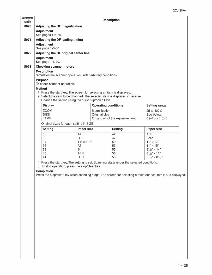
2CJ/2FA-1
1-4-25
MaintenanceDescriptionitem No.
U070 Adjusting the DF magnification
AdjustmentSee pages 1-6-78.
U071 Adjusting the DF leading timing
AdjustmentSee page 1-6-80.
U072 Adjusting the DF original center line
AdjustmentSee page 1-6-79.
U073 Checking scanner motors
DescriptionSimulates the scanner operation under arbitrary conditions.
PurposeTo check scanner operation.
Method1. Press the start key. The screen for selecting an item is displayed.2. Select the item to be changed. The selected item is displayed in reverse.3. Change the setting using the cursor up/down keys.
Display Operating conditions Setting range
ZOOM Magnification 25 to 400%SIZE Original size See below.LAMP On and off of the exposure lamp 0 (off) or 1 (on)
Original sizes for each setting in SIZE
Setting Paper size Setting Paper size
8 A4 42 A5R9 B5 47 Folio24 11" × 81/2" 52 11" × 17"36 A3 53 11" × 15"39 B4 55 81/2" × 14"40 A4R 56 81/2" × 11"41 B5R 58 51/2" × 81/2"
4. Press the start key. The setting is set. Scanning starts under the selected conditions.5. To stop operation, press the stop/clear key.
CompletionPress the stop/clear key when scanning stops. The screen for selecting a maintenance item No. is displayed.
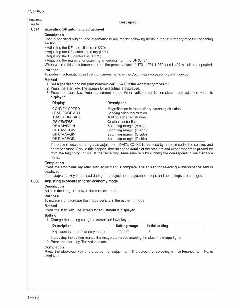
MaintenanceDescriptionitem No.
2CJ/2FA-2
1-4-26
U074 Executing DF automatic adjustment
DescriptionUses a specified original and automatically adjusts the following items in the document processor scanningsection.• Adjusting the DF magnification (U070)• Adjusting the DF scanning timing (U071)• Adjusting the DF center line (U072)• Adjusting the margins for scanning an original from the DF (U404)When you run this maintenance mode, the preset values of U70, U071, U072, and U404 will also be updated.
PurposeTo perform automatic adjustment of various items in the document processor scanning section.
Method1. Set a specified original (part number: 2AC68241) in the document processor.2. Press the start key. The screen for executing is displayed.3. Press the start key. Auto adjustment starts. When adjustment is complete, each adjusted value is
displayed.
Display Description
CONVEY SPEED Magnification in the auxiliary scanning directionLEAD EDGE ADJ Leading edge registrationTRAIL EDGE ADJ Trailing edge registrationDF CENTER Original center lineDF A MARGIN Scanning margin (A side)DF B MARGIN Scanning margin (B side)DF C MARGIN Scanning margin (C side)DF D MARGIN Scanning margin (D side)
If a problem occurs during auto adjustment, DATA: XX (XX is replaced by an error code) is displayed andoperation stops. Should this happen, determine the details of the problem and either repeat the procedurefrom the beginning, or adjust the remaining items manually by running the corresponding maintenanceitems.
CompletionPress the stop/clear key after auto adjustment is complete. The screen for selecting a maintenance item isdisplayed.If the stop/clear key is pressed during auto adjustment, adjustment stops and no settings are changed.
U080 Adjusting exposure in toner economy mode
DescriptionAdjusts the image density in the eco-print mode.
PurposeTo increase or decrease the image density in the eco-print mode.
MethodPress the start key. The screen for adjustment is displayed.
Setting1. Change the setting using the cursor up/down keys.
Description Setting range Initial setting
Exposure is toner economy mode –12 to 0 –6
Increasing the setting makes the image darker; decreasing it makes the image lighter.2. Press the start key. The value is set.
CompletionPress the stop/clear key at the screen for adjustment. The screen for selecting a maintenance item No. isdisplayed.
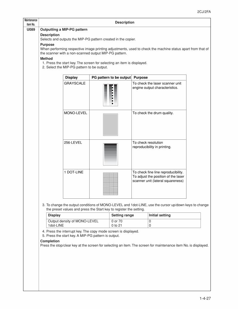
2CJ/2FA
1-4-27
MaintenanceDescriptionitem No.
U089 Outputting a MIP-PG pattern
DescriptionSelects and outputs the MIP-PG pattern created in the copier.
PurposeWhen performing respective image printing adjustments, used to check the machine status apart from that ofthe scanner with a non-scanned output MIP-PG pattern.
Method1. Press the start key. The screen for selecting an item is displayed.2. Select the MIP-PG pattern to be output.
Display
GRAYSCALE To check the laser scanner unit engine output characteristics.
MONO-LEVEL To check the drum quality.
256-LEVEL To check resolution reproducibility in printing.
1 DOT-LINE To check fine line reproducibility.To adjust the position of the laser scanner unit (lateral squareness)
PG pattern to be output Purpose
3. To change the output conditions of MONO-LEVEL and 1dot-LINE, use the cursor up/down keys to changethe preset values and press the Start key to register the setting.
Display Setting range Initial setting
Output density of MONO-LEVEL 0 or 70 01dot-LINE 0 to 21 0
4. Press the interrupt key. The copy mode screen is displayed.5. Press the start key. A MIP-PG pattern is output.
CompletionPress the stop/clear key at the screen for selecting an item. The screen for maintenance item No. is displayed.
MaintenanceDescriptionitem No.
2CJ/2FA
1-4-28
U091 Checking shading
DescriptionPerforms scanning under the same conditions as before and after shading is performed, displaying the originalscanning values at nine points of the contact glass.
PurposeTo check the change in original scanning values before and after shading. The results may be used to decidethe causes for fixing unevenness (uneven density) of the gray area of an image: either due to optical (shadingor CCD) or other problems.Also to check the causes for a white or black line appearing longitudinally.
Method1. Press the start key. The screen for selecting an item is displayed.2. Select the item to be operated. The selected item is displayed in reverse.
Display Description
SHD BEFORE Performs scanning before shading and displays the result.SHD AFTER Performs scanning after shading and displays the result.
3. Press the start key. Scanning is performed under the selected conditions and the result is displayed.When scanning is performed before shading, the scan value at the machine center should be slightlydifferent from those at the machine front and rear. When scanning is performed after shading, there shouldbe no difference between respective values. Any differences between the values at machine front and rearindicates that scanner problem causes the fixing unevenness.If the displayed results indicate no shading problems, the fixing unevenness (uneven copy density) iscaused by factors other than in the scanner section (shading or CCD).If a black line appears, the cause may assumed to be based on the results of the scanning operation beforeshading: if a white line appears, they may be assumed based on the results of the scanning operation aftershading. Note that depending on the thickness and location of the black or white line, it may not be possibleto use this method to determine the cause. This is because the displayed values obtained from scanning atthe limit of nine points are insufficient to provide significant information.
20 mm from the machine left
200 mm from the machine left
400 mm from the machine left
Machine center100 mm from the machine center toward machine front
100 mm from the machine center toward machine rear
Figure 1-4-2
4. To return to the screen for selecting an item, press the stop/clear key.
CompletionPress the stop/clear key at the screen for selecting an item. The screen for entering a maintenance item isdisplayed.
2CJ/2FA-1
1-4-29
MaintenanceDescriptionitem No.
U092 Adjusting the scanner automatically
DescriptionMakes auto scanner adjustments in the order below using the specified original.• Adjusting the scanner center line (U067)• Adjusting the scanner leading edge registration (U066)• Adjusting the scanner magnification in the auxiliary direction (U065)• Adjusting the margins for scanning an original on the contact glass (U403)When this maintenance item is performed, the settings in U065, U066, U067 and U403 are also changed.
PurposeUsed to make respective auto adjustments for the scanner.
Method1. Place the specified original (P/N: 2A068020) on the contact glass.2. Press the start key. The screen for executing is displayed.3. Press the start key. Auto adjustment starts. When adjustment is complete, each adjusted value is
displayed.
Display Description
SCAN CENTER Scanner center lineSCAN TIMING Scanner leading registrationSUB SCAN Scanner magnification in the auxiliary directionMAIN SCAN Scanner magnification in the main scanning directionSCAN A MARGIN Scanner reading margin (A side)SCAN B MARGIN Scanner reading margin (B side)SCAN C MARGIN Scanner reading margin (C side)SCAN D MARGIN Scanner reading margin (D side)
If a problem occurs during auto adjustment, DATA: XX (XX is replaced by an error code) is displayed andoperation stops. Should this happen, determine the details of the problem and either repeat the procedurefrom the beginning, or adjust the remaining items manually by running the corresponding maintenanceitems.Since the scanner magnification in the main direction is not automatically adjusted, use U065 for thisadjustment.
CompletionPress the stop/clear key after auto adjustment is complete. The screen for selecting a maintenance item No. isdisplayed.If the stop/clear key is pressed during auto adjustment, adjustment stops and no settings are changed.
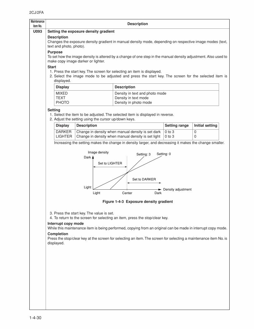
MaintenanceDescriptionitem No.
2CJ/2FA
1-4-30
U093 Setting the exposure density gradient
DescriptionChanges the exposure density gradient in manual density mode, depending on respective image modes (text,text and photo, photo).
PurposeTo set how the image density is altered by a change of one step in the manual density adjustment. Also used tomake copy image darker or lighter.
Start1. Press the start key. The screen for selecting an item is displayed.2. Select the image mode to be adjusted and press the start key. The screen for the selected item is
displayed.
Display Description
MIXED Density in text and photo modeTEXT Density in text modePHOTO Density in photo mode
Setting1. Select the item to be adjusted. The selected item is displayed in reverse.2. Adjust the setting using the cursor up/down keys.
Display Description Setting range Initial setting
DARKER Change in density when manual density is set dark 0 to 3 0LIGHTER Change in density when manual density is set light 0 to 3 0
Increasing the setting makes the change in density larger, and decreasing it makes the change smaller.
Image density
Density adjustment
Dark
Light
Light Center Dark
Setting: 0Setting: 3
Set to DARKER
Set to LIGHTER
Figure 1-4-3 Exposure density gradient
3. Press the start key. The value is set.4. To return to the screen for selecting an item, press the stop/clear key.
Interrupt copy modeWhile this maintenance item is being performed, copying from an original can be made in interrupt copy mode.
CompletionPress the stop/clear key at the screen for selecting an item. The screen for selecting a maintenance item No. isdisplayed.
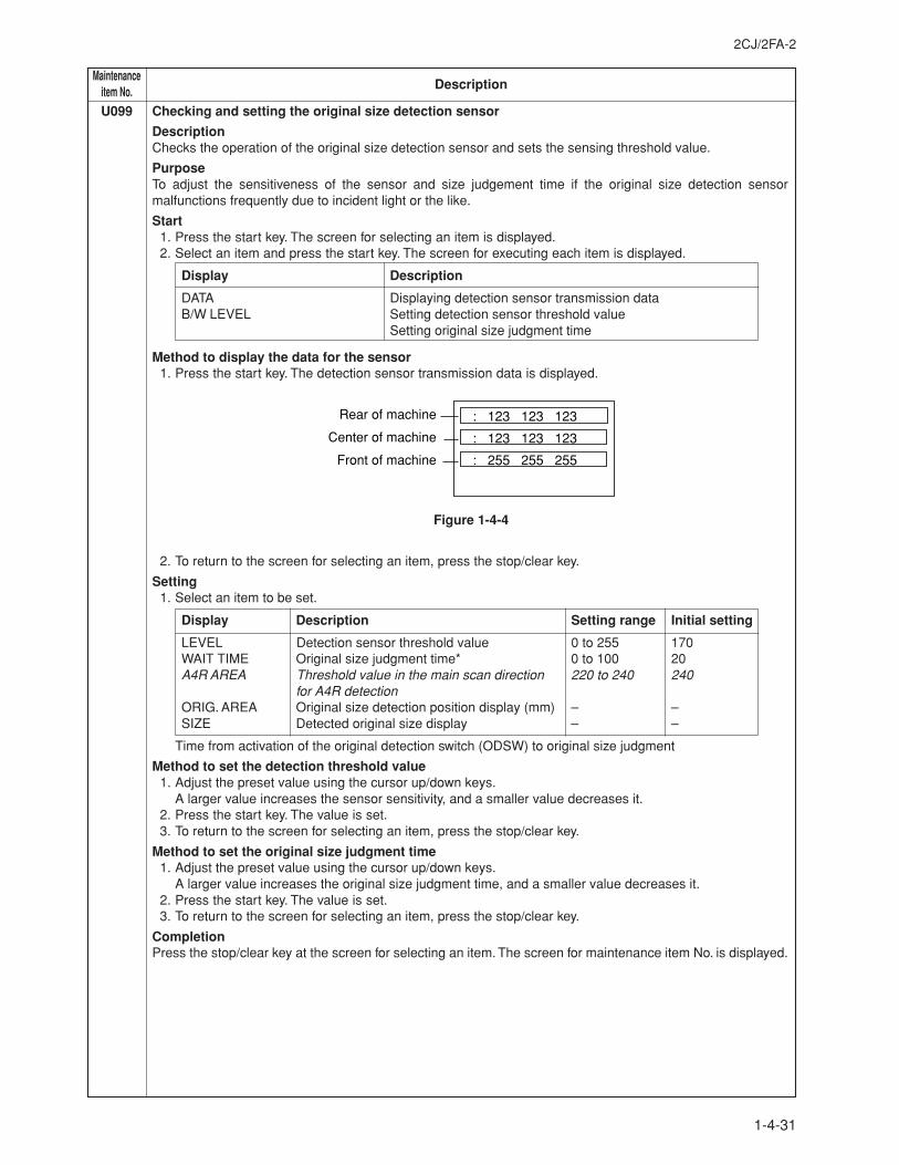
2CJ/2FA-2
1-4-31
MaintenanceDescriptionitem No.
U099 Checking and setting the original size detection sensor
DescriptionChecks the operation of the original size detection sensor and sets the sensing threshold value.
PurposeTo adjust the sensitiveness of the sensor and size judgement time if the original size detection sensormalfunctions frequently due to incident light or the like.
Start1. Press the start key. The screen for selecting an item is displayed.2. Select an item and press the start key. The screen for executing each item is displayed.
Display Description
DATA Displaying detection sensor transmission dataB/W LEVEL Setting detection sensor threshold value
Setting original size judgment time
Method to display the data for the sensor1. Press the start key. The detection sensor transmission data is displayed.
: 123 123 123
: 123 123 123
: 255 255 255
Rear of machine
Center of machine
Front of machine
Figure 1-4-4
2. To return to the screen for selecting an item, press the stop/clear key.
Setting1. Select an item to be set.
Display Description Setting range Initial setting
LEVEL Detection sensor threshold value 0 to 255 170WAIT TIME Original size judgment time* 0 to 100 20A4R AREA Threshold value in the main scan direction 220 to 240 240
for A4R detectionORIG. AREA Original size detection position display (mm) – –SIZE Detected original size display – –
Time from activation of the original detection switch (ODSW) to original size judgment
Method to set the detection threshold value1. Adjust the preset value using the cursor up/down keys.
A larger value increases the sensor sensitivity, and a smaller value decreases it.2. Press the start key. The value is set.3. To return to the screen for selecting an item, press the stop/clear key.
Method to set the original size judgment time1. Adjust the preset value using the cursor up/down keys.
A larger value increases the original size judgment time, and a smaller value decreases it.2. Press the start key. The value is set.3. To return to the screen for selecting an item, press the stop/clear key.
CompletionPress the stop/clear key at the screen for selecting an item. The screen for maintenance item No. is displayed.
MaintenanceDescriptionitem No.
2CJ/2FA-1
1-4-32
U100 Checking the operation of main high voltage
DescriptionPerforms the main charging output.
PurposeTo check the main charging. Do not change the preset value.
StartPress the start key. The screen for selecting an item is displayed.
Display Description
DSP DATA Changing the grid control voltageMC ON Turning the main charger onMC ON/OFF Turning the main charger on and offLASER ON/OFF Turning the main charger on and the laser scanner unit on and offLASER POWER CHECK Turning the main charger on and the laser scanner unit on and off
Method for main chager output1. Select the main charger output on the screen for selecting an item: select one from MC ON, MC ON/OFF
or LASER ON/OFF on the touch panel. The selected operation starts.2. To stop operation, press the stop/clear key.
Setting the grid control voltage1. Press the DSP DATA on the touch panel of the screen for selecting an item.2. Change the setting using the ∗ or # keys.
Description Setting range Reference value
Grid control voltage 77 to 230 115
Increasing the setting makes the surface potential higher, and decreasing it makes the potential lower.Change in value per step: approximately 3.6 V
Interrupt copy modeWhile this maintenance item is being performed, copying from an original can be made in interrupt copy mode.
CompletionPress the stop/clear key at the screen for selecting an item when main charger output stops. The screen forselecting a maintenance item No. is displayed.
2CJ/2FA-1
1-4-33
MaintenanceDescriptionitem No.
U101 Setting the other high voltages
DescriptionSets the developing bias control voltage, the transfer control voltage, and the separation control voltage orchecks the output of these voltages.
PurposeTo check or change the developing bias, the transfer voltage, and the separation voltage.
MethodPress the start key. The screen for selecting an item is displayed.
Display Description
DEV BIAS SET Setting of developing bias control voltageTC SET Setting and output check of transfer control voltage
Setting: developing bias control voltage1. Press the DEV BIAS SET on the touch panel of the screen for selecting an item.2. Select an item to be set.
Display Description Setting range Initial setting
DB DATA Developing bias step control final voltage 0 to 255 184DB DATA2 Developing bias step control initial voltage 0 to 255 62 (63 cpm)
70 (75 cpm)
3. Change the setting using the cursor up/down keys.Increasing the setting makes the image darker; decreasing it makes the image lighter.
4. Press the start key. The value is set.
Setting: transfer bias control voltage1. Press the TC SET on the touch panel of the screen for selecting an item.2. Select an item to be set.
Display Description Setting range Initial setting
TC DATA Transfer control voltage for simplex copying 0 to 255 150 (63 cpm)100 (75 cpm)
TC DATA (DUP) Transfer control voltage for duplex copying 0 to 255 200 (63 cpm)100 (75 cpm)
TC DATA2 Transfer control voltage for simplex copying 0 to 255 100 (75 cpm)(50K or later)
TC DATA2 (DUP) Transfer control voltage for duplex copying 0 to 255 100 (75 cpm)(50K or later)
TC ON Transfer voltage output ON – –
3. Change the setting using the ∗ or # keys.Increasing the setting makes the transfer voltage higher, and decreasing it makes the voltage lower.Press the TC ON on the touch panel. The currently set transfer voltage is output. To stop the transfervoltage output, press the stop/clear key.
4. Press the start key. The value is set.
Interrupt copy modeWhile this maintenance item is being performed, copying from an original can be made in interrupt copy mode.
CompletionPress the stop/clear key at the screen for selecting an item. The screen for maintenance item No. is displayed.
MaintenanceDescriptionitem No.
2CJ/2FA-2
1-4-34
U102 Setting the cleaning interval for the main charger
DescriptionExecutes a cleaning operation for the main charger and changes the intervals at which the main charger iscleaned.
PurposeTo check the cleaning operation for the main charger. Changes the setting of cleaning operation start timing toON when a large scale of copy is frequently performed such as the number of copy at one time exceeding1000.
MethodPress the start key. The screen for selecting an item is displayed.
Display Description
MC ADJUST DATA Main charger cleaning operation intervalsMC TEST RUN Main charger cleaning operation ONMC ADJUST MODE Main charger cleaning operation start timing
Setting: main charger cleaning operation intervals1. Change the setting using the ∗ or # keys.
Setting range: 1 to 2 (unit: 1,000 sheets)Initial setting: 1If you select MC TEST RUN, the main charger cleaning operation will be performed once.
2. Press the start key. The value is set.
Setting: main charger cleaning operation start timing1. Press the MC ADJUST MODE on the touch panel of the screen for selecting an item.2. Select ON or OFF. The selected item is displayed in reverse. Initial setting: OFF
If ON is selected, when the preset number of sheets for charger cleaning operation intervals is exceededduring copying, the copier stops copying temporarily and starts charger cleaning operation.If OFF is selected, when the preset number of sheets for charger cleaning operation is exceeded duringcopying, the copier continues copying to the end and then starts charger cleaning operation.
3. Press the start key. The value is set.
CompletionPress the stop/clear key. The screen for selecting a maintenance item No. is displayed.
U110 Checking/clearing the drum count
DescriptionDisplays the drum counts for checking, clearing or changing the figure, which is used as a reference whencorrecting the main charger potential output.
PurposeTo check the drum status. Also used to clear the count after replacing the drum during regular maintenance.Since the count was cleared before shipping, do not clear it when installing.
MethodPress the start key. The drum counter count is displayed.
Clearing1. Press the CLEAR on the touch panel.2. Press the start key. The count is cleared, and the screen for selecting a maintenance item No. is displayed.
Setting1. Enter a seven-digit count using the numeric keys.2. Press the start key. The count is set, and the screen for selecting a maintenance item No. is displayed.
CompletionTo exit the maintenance mode without changing the count, press the stop/clear key. The screen for selecting amaintenance item No. is displayed.
2CJ/2FA-2
1-4-35
MaintenanceDescriptionitem No.
U111 Checking/clearing the drum drive time
DescriptionDisplays the drum drive time for checking, clearing or changing a figure, which is used as a reference whencorrecting the high voltage based on time.
PurposeTo check the drum status. Also used to clear the drive time after replacing the drum.
MethodPress the start key. The drum drive time is displayed.
Clearing1. Press the reset key.2. Press the start key. The drive time is cleared, and the screen for selecting a maintenance item No. is
displayed.
Setting1. Enter a five-digit drive time using the numeric keys.2. Press the start key. The drive time is set, and the screen for selecting a maintenance item No. is displayed.
CompletionTo exit the maintenance mode without changing the drive time, press the stop/clear key. The screen forselecting a maintenance item No. is displayed.
U125 High pressure setting for special papers (for 75 cpm only)
DescriptionAdjusts the high pressure output ON/OFF timing in the recycle paper mode.
PurposePerform the setting if the transfer failure occurred when the recycle paper is used.
MethodPress the start key. The screen for adjustment is displayed.
Setting1. Select the item to be set.2. Change the setting using the cursor up/down keys.
Display Setting Setting range Initial setting
RECYCLE TC ON Transfer charge ON timing in -30 to +30 mm 5the recycle paper mode
RECYCLE TC CHNG Transfer charge output change 0 to +39 mm 25timing in the recycle paper mode
RECYCLE MARGIN Leading edge cutting rate in +5 to +100 mm 60the recycle paper mode
3. Press the start key. The value is set.
Interrupt copy modeWhile this maintenance item is being performed, copying from an original can be made in interrupt copy mode.
CompletionPress the stop/clear key at the screen for adjustment. The screen for selecting a maintenance item No. isdisplayed.
MaintenanceDescriptionitem No.
2CJ/2FA-2
1-4-36
U127 Checking/clearing the transfer count (for 75 cpm only)
DescriptionSetting and changes the transfer counter value.
PurposeTo clear the transfer counts after replacing the transfer charger belt during maintenance or for other reasons.
MethodPress the start key. The transfer counter value is displayed.
Clearing1. Press the CLEAR on the touch panel.2. Press the start key. The value is cleared. The screen for selecting a maintenance item No. is displayed.
Setting1. Enter a seven-digit value using the numeric keys.2. Press the start key. The value is set. The screen for selecting a maintenance item No. is displayed.
CompletionTo exit this maintenance item without changing the count, press the stop/clear key. The screen for selecting amaintenance item No. is displayed.
U129 Adjusting the transfer timing
DescriptionAdjusts the ON/OFF timing of transfer charging output.
PurposeUsed when faulty drum separation on paper occurs.
MethodPress the start key. The screen for adjustment is displayed.
Setting1. Select the item to be set. The selected item is displayed in reverse.2. Change the setting using the cursor up/down keys.
Display Setting Setting range Initial setting
TC ON Transfer charging output ON timing -30 to +30 mm 0TC OFF Transfer charging output OFF timing -40 to +100 mm 0
3. Press the start key. The value is set.
Interrupt copy modeWhile this maintenance item is being performed, copying from an original can be made in interrupt copy mode.
CompletionPress the stop/clear key at the screen for adjustment. The screen for selecting a maintenance item No. isdisplayed.
1-4-35-1

1-4-37
2CJ/2FA-2
This page is intentionally left blank.
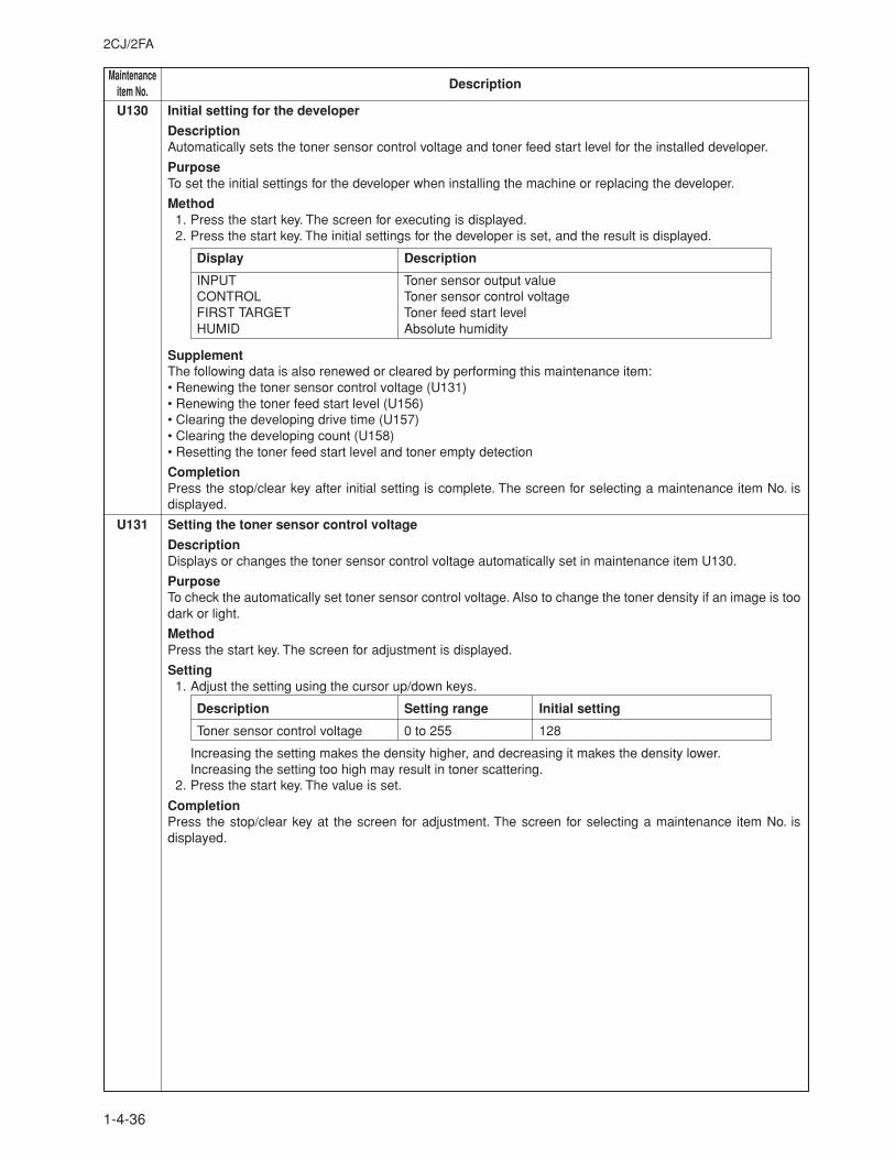
MaintenanceDescriptionitem No.
2CJ/2FA
1-4-36
U130 Initial setting for the developer
DescriptionAutomatically sets the toner sensor control voltage and toner feed start level for the installed developer.
PurposeTo set the initial settings for the developer when installing the machine or replacing the developer.
Method1. Press the start key. The screen for executing is displayed.2. Press the start key. The initial settings for the developer is set, and the result is displayed.
Display Description
INPUT Toner sensor output valueCONTROL Toner sensor control voltageFIRST TARGET Toner feed start levelHUMID Absolute humidity
SupplementThe following data is also renewed or cleared by performing this maintenance item:• Renewing the toner sensor control voltage (U131)• Renewing the toner feed start level (U156)• Clearing the developing drive time (U157)• Clearing the developing count (U158)• Resetting the toner feed start level and toner empty detection
CompletionPress the stop/clear key after initial setting is complete. The screen for selecting a maintenance item No. isdisplayed.
U131 Setting the toner sensor control voltage
DescriptionDisplays or changes the toner sensor control voltage automatically set in maintenance item U130.
PurposeTo check the automatically set toner sensor control voltage. Also to change the toner density if an image is toodark or light.
MethodPress the start key. The screen for adjustment is displayed.
Setting1. Adjust the setting using the cursor up/down keys.
Description Setting range Initial setting
Toner sensor control voltage 0 to 255 128
Increasing the setting makes the density higher, and decreasing it makes the density lower.Increasing the setting too high may result in toner scattering.
2. Press the start key. The value is set.
CompletionPress the stop/clear key at the screen for adjustment. The screen for selecting a maintenance item No. isdisplayed.
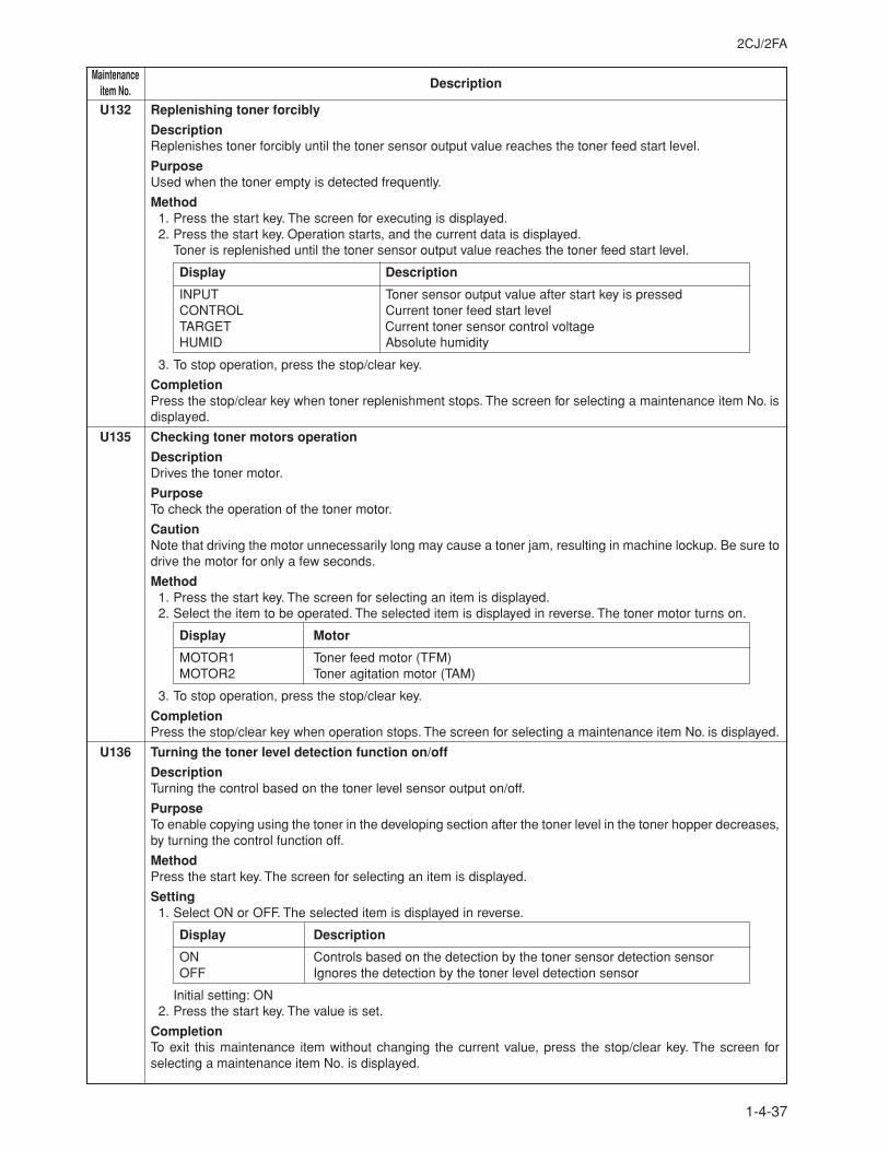
2CJ/2FA
1-4-37
MaintenanceDescriptionitem No.
U132 Replenishing toner forcibly
DescriptionReplenishes toner forcibly until the toner sensor output value reaches the toner feed start level.
PurposeUsed when the toner empty is detected frequently.
Method1. Press the start key. The screen for executing is displayed.2. Press the start key. Operation starts, and the current data is displayed.
Toner is replenished until the toner sensor output value reaches the toner feed start level.
Display Description
INPUT Toner sensor output value after start key is pressedCONTROL Current toner feed start levelTARGET Current toner sensor control voltageHUMID Absolute humidity
3. To stop operation, press the stop/clear key.
CompletionPress the stop/clear key when toner replenishment stops. The screen for selecting a maintenance item No. isdisplayed.
U135 Checking toner motors operation
DescriptionDrives the toner motor.
PurposeTo check the operation of the toner motor.
CautionNote that driving the motor unnecessarily long may cause a toner jam, resulting in machine lockup. Be sure todrive the motor for only a few seconds.
Method1. Press the start key. The screen for selecting an item is displayed.2. Select the item to be operated. The selected item is displayed in reverse. The toner motor turns on.
Display Motor
MOTOR1 Toner feed motor (TFM)MOTOR2 Toner agitation motor (TAM)
3. To stop operation, press the stop/clear key.
CompletionPress the stop/clear key when operation stops. The screen for selecting a maintenance item No. is displayed.
U136 Turning the toner level detection function on/off
DescriptionTurning the control based on the toner level sensor output on/off.
PurposeTo enable copying using the toner in the developing section after the toner level in the toner hopper decreases,by turning the control function off.
MethodPress the start key. The screen for selecting an item is displayed.
Setting1. Select ON or OFF. The selected item is displayed in reverse.
Display Description
ON Controls based on the detection by the toner sensor detection sensorOFF Ignores the detection by the toner level detection sensor
Initial setting: ON2. Press the start key. The value is set.
CompletionTo exit this maintenance item without changing the current value, press the stop/clear key. The screen forselecting a maintenance item No. is displayed.
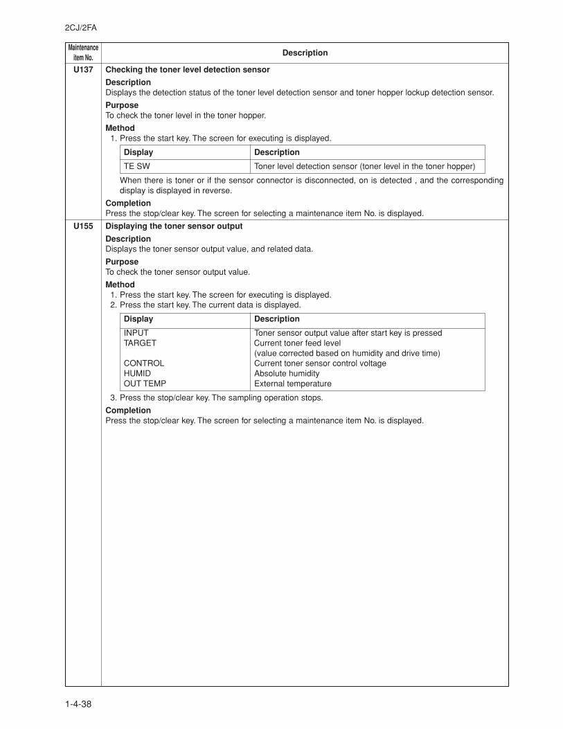
MaintenanceDescriptionitem No.
2CJ/2FA
1-4-38
U137 Checking the toner level detection sensor
DescriptionDisplays the detection status of the toner level detection sensor and toner hopper lockup detection sensor.
PurposeTo check the toner level in the toner hopper.
Method1. Press the start key. The screen for executing is displayed.
Display Description
TE SW Toner level detection sensor (toner level in the toner hopper)
When there is toner or if the sensor connector is disconnected, on is detected , and the correspondingdisplay is displayed in reverse.
CompletionPress the stop/clear key. The screen for selecting a maintenance item No. is displayed.
U155 Displaying the toner sensor output
DescriptionDisplays the toner sensor output value, and related data.
PurposeTo check the toner sensor output value.
Method1. Press the start key. The screen for executing is displayed.2. Press the start key. The current data is displayed.
Display Description
INPUT Toner sensor output value after start key is pressedTARGET Current toner feed level
(value corrected based on humidity and drive time)CONTROL Current toner sensor control voltageHUMID Absolute humidityOUT TEMP External temperature
3. Press the stop/clear key. The sampling operation stops.
CompletionPress the stop/clear key. The screen for selecting a maintenance item No. is displayed.
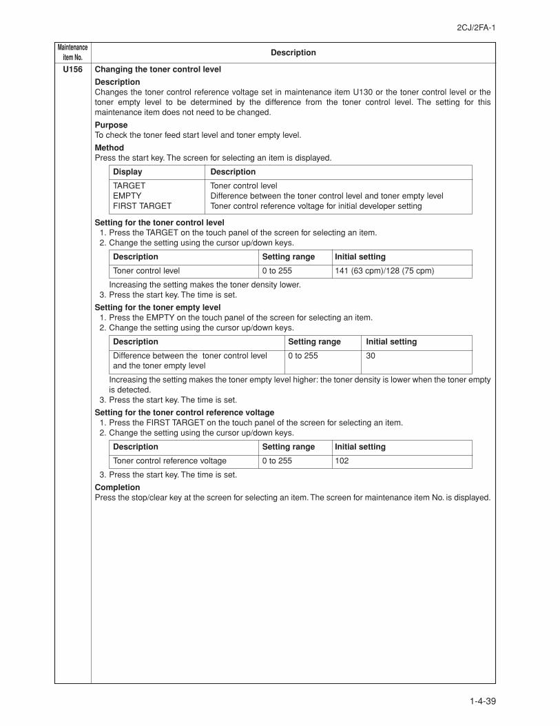
2CJ/2FA-1
1-4-39
MaintenanceDescriptionitem No.
U156 Changing the toner control level
DescriptionChanges the toner control reference voltage set in maintenance item U130 or the toner control level or thetoner empty level to be determined by the difference from the toner control level. The setting for thismaintenance item does not need to be changed.
PurposeTo check the toner feed start level and toner empty level.
MethodPress the start key. The screen for selecting an item is displayed.
Display Description
TARGET Toner control levelEMPTY Difference between the toner control level and toner empty levelFIRST TARGET Toner control reference voltage for initial developer setting
Setting for the toner control level1. Press the TARGET on the touch panel of the screen for selecting an item.2. Change the setting using the cursor up/down keys.
Description Setting range Initial setting
Toner control level 0 to 255 141 (63 cpm)/128 (75 cpm)
Increasing the setting makes the toner density lower.3. Press the start key. The time is set.
Setting for the toner empty level1. Press the EMPTY on the touch panel of the screen for selecting an item.2. Change the setting using the cursor up/down keys.
Description Setting range Initial setting
Difference between the toner control level 0 to 255 30and the toner empty level
Increasing the setting makes the toner empty level higher: the toner density is lower when the toner emptyis detected.
3. Press the start key. The time is set.
Setting for the toner control reference voltage1. Press the FIRST TARGET on the touch panel of the screen for selecting an item.2. Change the setting using the cursor up/down keys.
Description Setting range Initial setting
Toner control reference voltage 0 to 255 102
3. Press the start key. The time is set.
CompletionPress the stop/clear key at the screen for selecting an item. The screen for maintenance item No. is displayed.
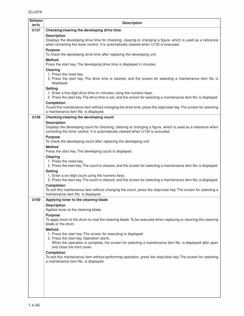
MaintenanceDescriptionitem No.
2CJ/2FA
1-4-40
U157 Checking/clearing the developing drive time
DescriptionDisplays the developing drive time for checking, clearing or changing a figure, which is used as a referencewhen correcting the toner control. It is automatically cleared when U130 is executed.
PurposeTo check the developing drive time after replacing the developing unit.
MethodPress the start key. The developing drive time is displayed in minutes.
Clearing1. Press the reset key.2. Press the start key. The drive time is cleared, and the screen for selecting a maintenance item No. is
displayed.
Setting1. Enter a five-digit drive time (in minutes) using the numeric keys.2. Press the start key. The drive time is set, and the screen for selecting a maintenance item No. is displayed.
CompletionTo exit this maintenance item without changing the drive time, press the stop/clear key. The screen for selectinga maintenance item No. is displayed.
U158 Checking/clearing the developing count
DescriptionDisplays the developing count for checking, clearing or changing a figure, which is used as a reference whencorrecting the toner control. It is automatically cleared when U130 is executed.
PurposeTo check the developing count after replacing the developing unit.
MethodPress the start key. The developing count is displayed.
Clearing1. Press the reset key.2. Press the start key. The count is cleared, and the screen for selecting a maintenance item No. is displayed.
Setting1. Enter a six-digit count using the numeric keys.2. Press the start key. The count is cleared, and the screen for selecting a maintenance item No. is displayed.
CompletionTo exit this maintenance item without changing the count, press the stop/clear key. The screen for selecting amaintenance item No. is displayed.
U160 Applying toner to the cleaning blade
DescriptionApplies toner to the cleaning blade.
PurposeTo apply toner to the drum to coat the cleaning blade. To be executed when replacing or cleaning the cleaningblade or the drum.
Method1. Press the start key. The screen for executing is displayed.2. Press the start key. Operation starts.
When the operation is complete, the screen for selecting a maintenance item No. is displayed after openand close the front cover.
CompletionTo exit this maintenance item without performing operation, press the stop/clear key. The screen for selectinga maintenance item No. is displayed.
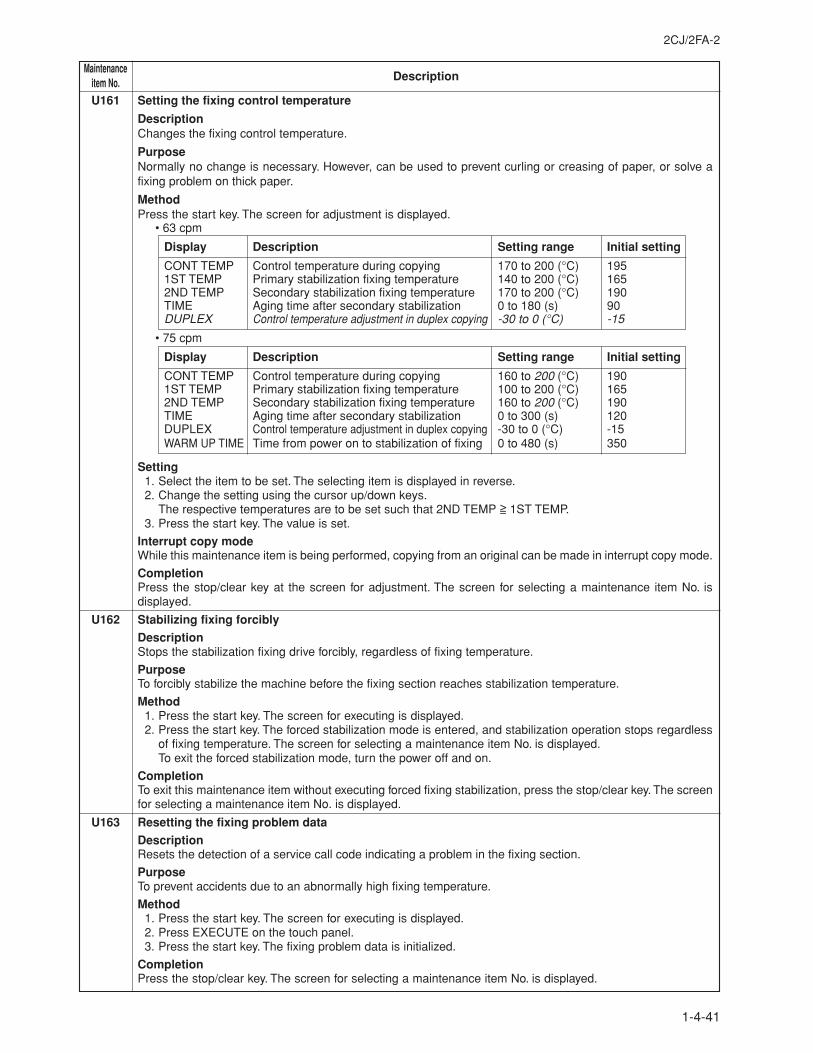
2CJ/2FA-2
1-4-41
MaintenanceDescriptionitem No.
U161 Setting the fixing control temperature
DescriptionChanges the fixing control temperature.
PurposeNormally no change is necessary. However, can be used to prevent curling or creasing of paper, or solve afixing problem on thick paper.
MethodPress the start key. The screen for adjustment is displayed.
• 63 cpm
Display Description Setting range Initial setting
CONT TEMP Control temperature during copying 170 to 200 (°C) 1951ST TEMP Primary stabilization fixing temperature 140 to 200 (°C) 1652ND TEMP Secondary stabilization fixing temperature 170 to 200 (°C) 190TIME Aging time after secondary stabilization 0 to 180 (s) 90DUPLEX Control temperature adjustment in duplex copying -30 to 0 (°C) -15
• 75 cpm
Display Description Setting range Initial setting
CONT TEMP Control temperature during copying 160 to 200 (°C) 1901ST TEMP Primary stabilization fixing temperature 100 to 200 (°C) 1652ND TEMP Secondary stabilization fixing temperature 160 to 200 (°C) 190TIME Aging time after secondary stabilization 0 to 300 (s) 120DUPLEX Control temperature adjustment in duplex copying -30 to 0 (°C) -15WARM UP TIME Time from power on to stabilization of fixing 0 to 480 (s) 350
Setting1. Select the item to be set. The selecting item is displayed in reverse.2. Change the setting using the cursor up/down keys.
The respective temperatures are to be set such that 2ND TEMP >= 1ST TEMP.3. Press the start key. The value is set.
Interrupt copy modeWhile this maintenance item is being performed, copying from an original can be made in interrupt copy mode.
CompletionPress the stop/clear key at the screen for adjustment. The screen for selecting a maintenance item No. isdisplayed.
U162 Stabilizing fixing forcibly
DescriptionStops the stabilization fixing drive forcibly, regardless of fixing temperature.
PurposeTo forcibly stabilize the machine before the fixing section reaches stabilization temperature.
Method1. Press the start key. The screen for executing is displayed.2. Press the start key. The forced stabilization mode is entered, and stabilization operation stops regardless
of fixing temperature. The screen for selecting a maintenance item No. is displayed.To exit the forced stabilization mode, turn the power off and on.
CompletionTo exit this maintenance item without executing forced fixing stabilization, press the stop/clear key. The screenfor selecting a maintenance item No. is displayed.
U163 Resetting the fixing problem data
DescriptionResets the detection of a service call code indicating a problem in the fixing section.
PurposeTo prevent accidents due to an abnormally high fixing temperature.
Method1. Press the start key. The screen for executing is displayed.2. Press EXECUTE on the touch panel.3. Press the start key. The fixing problem data is initialized.
CompletionPress the stop/clear key. The screen for selecting a maintenance item No. is displayed.
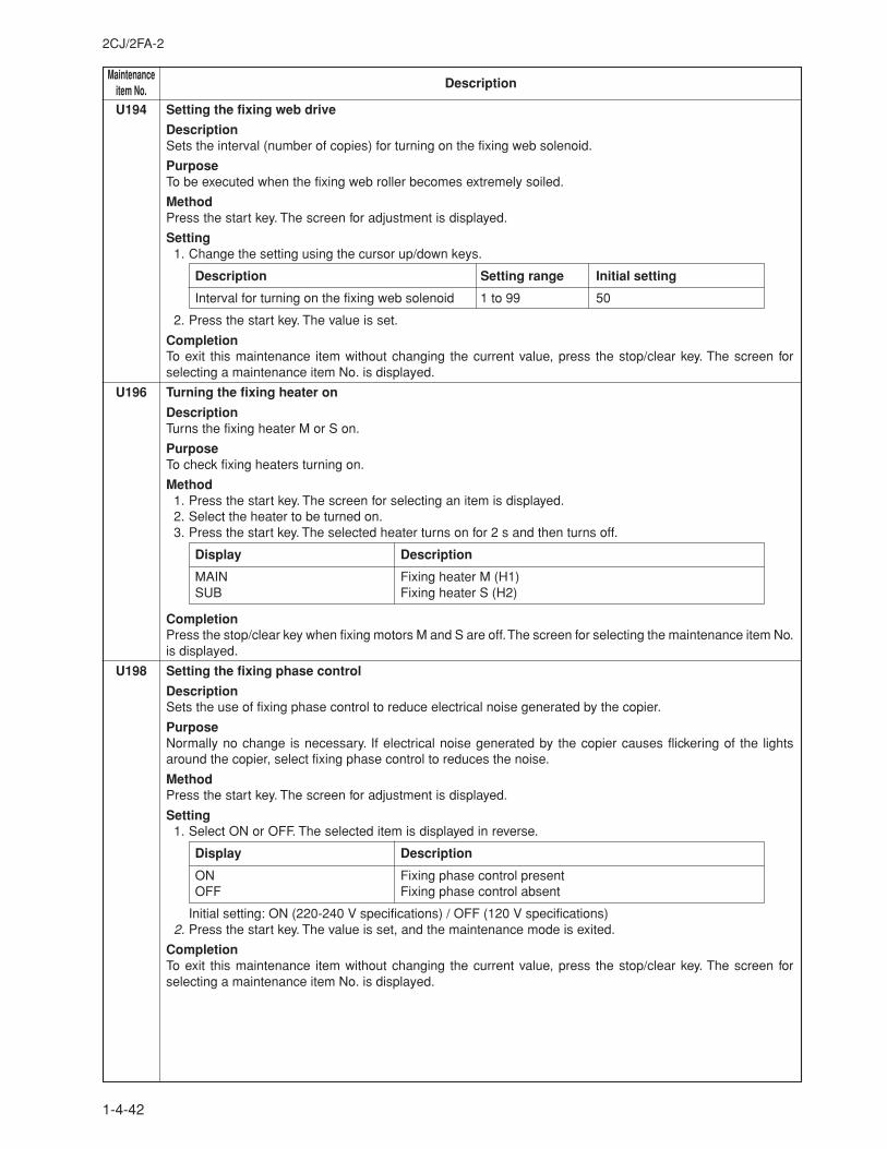
MaintenanceDescriptionitem No.
2CJ/2FA-2
1-4-42
U194 Setting the fixing web drive
DescriptionSets the interval (number of copies) for turning on the fixing web solenoid.
PurposeTo be executed when the fixing web roller becomes extremely soiled.
MethodPress the start key. The screen for adjustment is displayed.
Setting1. Change the setting using the cursor up/down keys.
Description Setting range Initial setting
Interval for turning on the fixing web solenoid 1 to 99 50
2. Press the start key. The value is set.
CompletionTo exit this maintenance item without changing the current value, press the stop/clear key. The screen forselecting a maintenance item No. is displayed.
U196 Turning the fixing heater on
DescriptionTurns the fixing heater M or S on.
PurposeTo check fixing heaters turning on.
Method1. Press the start key. The screen for selecting an item is displayed.2. Select the heater to be turned on.3. Press the start key. The selected heater turns on for 2 s and then turns off.
Display Description
MAIN Fixing heater M (H1)SUB Fixing heater S (H2)
CompletionPress the stop/clear key when fixing motors M and S are off. The screen for selecting the maintenance item No.is displayed.
U198 Setting the fixing phase control
DescriptionSets the use of fixing phase control to reduce electrical noise generated by the copier.
PurposeNormally no change is necessary. If electrical noise generated by the copier causes flickering of the lightsaround the copier, select fixing phase control to reduces the noise.
MethodPress the start key. The screen for adjustment is displayed.
Setting1. Select ON or OFF. The selected item is displayed in reverse.
Display Description
ON Fixing phase control presentOFF Fixing phase control absent
Initial setting: ON (220-240 V specifications) / OFF (120 V specifications)2. Press the start key. The value is set, and the maintenance mode is exited.
CompletionTo exit this maintenance item without changing the current value, press the stop/clear key. The screen forselecting a maintenance item No. is displayed.
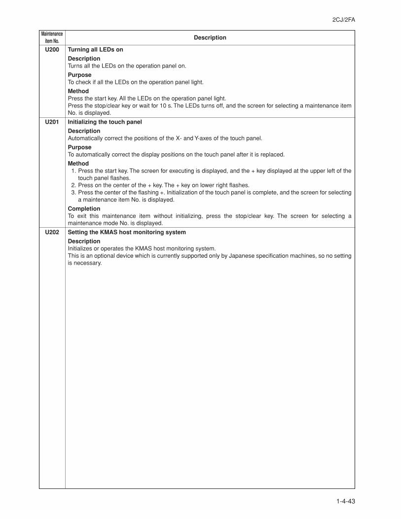
2CJ/2FA
1-4-43
MaintenanceDescriptionitem No.
U200 Turning all LEDs on
DescriptionTurns all the LEDs on the operation panel on.
PurposeTo check if all the LEDs on the operation panel light.
MethodPress the start key. All the LEDs on the operation panel light.Press the stop/clear key or wait for 10 s. The LEDs turns off, and the screen for selecting a maintenance itemNo. is displayed.
U201 Initializing the touch panel
DescriptionAutomatically correct the positions of the X- and Y-axes of the touch panel.
PurposeTo automatically correct the display positions on the touch panel after it is replaced.
Method1. Press the start key. The screen for executing is displayed, and the + key displayed at the upper left of the
touch panel flashes.2. Press on the center of the + key. The + key on lower right flashes.3. Press the center of the flashing +. Initialization of the touch panel is complete, and the screen for selecting
a maintenance item No. is displayed.
CompletionTo exit this maintenance item without initializing, press the stop/clear key. The screen for selecting amaintenance mode No. is displayed.
U202 Setting the KMAS host monitoring system
DescriptionInitializes or operates the KMAS host monitoring system.This is an optional device which is currently supported only by Japanese specification machines, so no settingis necessary.
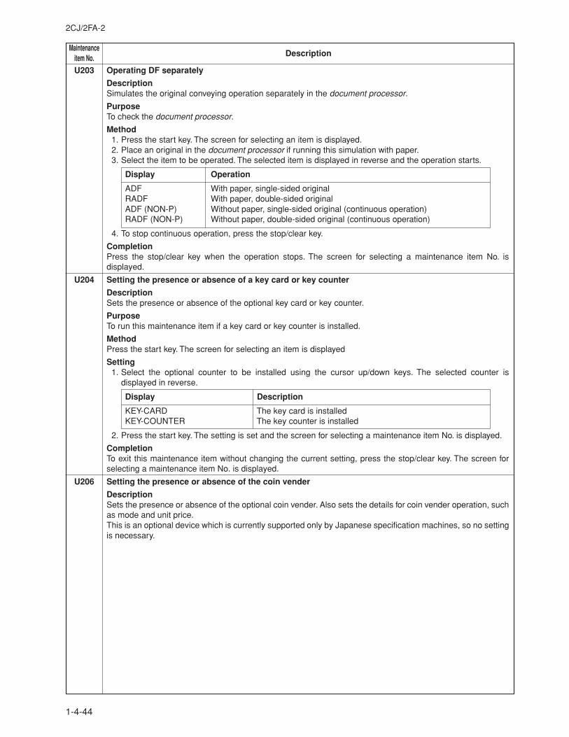
MaintenanceDescriptionitem No.
2CJ/2FA-2
1-4-44
U203 Operating DF separately
DescriptionSimulates the original conveying operation separately in the document processor.
PurposeTo check the document processor.
Method1. Press the start key. The screen for selecting an item is displayed.2. Place an original in the document processor if running this simulation with paper.3. Select the item to be operated. The selected item is displayed in reverse and the operation starts.
Display Operation
ADF With paper, single-sided originalRADF With paper, double-sided originalADF (NON-P) Without paper, single-sided original (continuous operation)RADF (NON-P) Without paper, double-sided original (continuous operation)
4. To stop continuous operation, press the stop/clear key.
CompletionPress the stop/clear key when the operation stops. The screen for selecting a maintenance item No. isdisplayed.
U204 Setting the presence or absence of a key card or key counter
DescriptionSets the presence or absence of the optional key card or key counter.
PurposeTo run this maintenance item if a key card or key counter is installed.
MethodPress the start key. The screen for selecting an item is displayed
Setting1. Select the optional counter to be installed using the cursor up/down keys. The selected counter is
displayed in reverse.
Display Description
KEY-CARD The key card is installedKEY-COUNTER The key counter is installed
2. Press the start key. The setting is set and the screen for selecting a maintenance item No. is displayed.
CompletionTo exit this maintenance item without changing the current setting, press the stop/clear key. The screen forselecting a maintenance item No. is displayed.
U206 Setting the presence or absence of the coin vender
DescriptionSets the presence or absence of the optional coin vender. Also sets the details for coin vender operation, suchas mode and unit price.This is an optional device which is currently supported only by Japanese specification machines, so no settingis necessary.
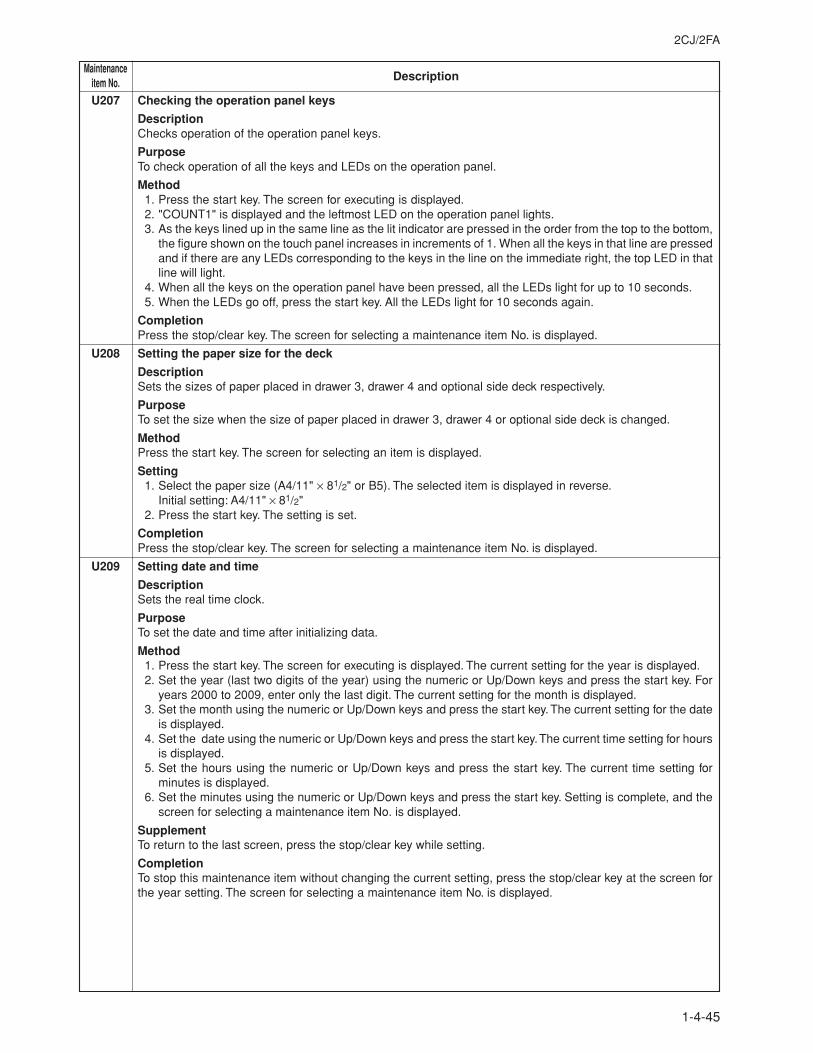
2CJ/2FA
1-4-45
MaintenanceDescriptionitem No.
U207 Checking the operation panel keys
DescriptionChecks operation of the operation panel keys.
PurposeTo check operation of all the keys and LEDs on the operation panel.
Method1. Press the start key. The screen for executing is displayed.2. "COUNT1" is displayed and the leftmost LED on the operation panel lights.
3. As the keys lined up in the same line as the lit indicator are pressed in the order from the top to the bottom,the figure shown on the touch panel increases in increments of 1. When all the keys in that line are pressedand if there are any LEDs corresponding to the keys in the line on the immediate right, the top LED in thatline will light.
4. When all the keys on the operation panel have been pressed, all the LEDs light for up to 10 seconds.5. When the LEDs go off, press the start key. All the LEDs light for 10 seconds again.
CompletionPress the stop/clear key. The screen for selecting a maintenance item No. is displayed.
U208 Setting the paper size for the deck
DescriptionSets the sizes of paper placed in drawer 3, drawer 4 and optional side deck respectively.
PurposeTo set the size when the size of paper placed in drawer 3, drawer 4 or optional side deck is changed.
MethodPress the start key. The screen for selecting an item is displayed.
Setting1. Select the paper size (A4/11" × 81/2" or B5). The selected item is displayed in reverse.
Initial setting: A4/11" × 81/2"2. Press the start key. The setting is set.
CompletionPress the stop/clear key. The screen for selecting a maintenance item No. is displayed.
U209 Setting date and time
DescriptionSets the real time clock.
PurposeTo set the date and time after initializing data.
Method1. Press the start key. The screen for executing is displayed. The current setting for the year is displayed.2. Set the year (last two digits of the year) using the numeric or Up/Down keys and press the start key. For
years 2000 to 2009, enter only the last digit. The current setting for the month is displayed.3. Set the month using the numeric or Up/Down keys and press the start key. The current setting for the date
is displayed.4. Set the date using the numeric or Up/Down keys and press the start key. The current time setting for hours
is displayed.5. Set the hours using the numeric or Up/Down keys and press the start key. The current time setting for
minutes is displayed.6. Set the minutes using the numeric or Up/Down keys and press the start key. Setting is complete, and the
screen for selecting a maintenance item No. is displayed.
SupplementTo return to the last screen, press the stop/clear key while setting.
CompletionTo stop this maintenance item without changing the current setting, press the stop/clear key at the screen forthe year setting. The screen for selecting a maintenance item No. is displayed.
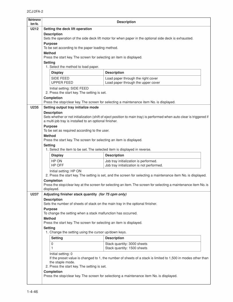
MaintenanceDescriptionitem No.
2CJ/2FA-2
1-4-46
U212 Setting the deck lift operation
DescriptionSets the operation of the side deck lift motor for when paper in the optional side deck is exhausted.
PurposeTo be set according to the paper loading method.
MethodPress the start key. The screen for selecting an item is displayed.
Setting1. Select the method to load paper.
Display Description
SIDE FEED Load paper through the right coverUPPER FEED Load paper through the upper cover
Initial setting: SIDE FEED2. Press the start key. The setting is set.
CompletionPress the stop/clear key. The screen for selecting a maintenance item No. is displayed.
U235 Setting output tray initialize mode
DescriptionSets whether or not initialization (shift of eject position to main tray) is performed when auto clear is triggered ifa multi-job tray is installed to an optional finisher.
PurposeTo be set as required according to the user.
MethodPress the start key. The screen for selecting an item is displayed.
Setting1. Select the item to be set. The selected item is displayed in reverse.
Display Description
HP ON Job tray initialization is performed.HP OFF Job tray initialization is not performed.
Initial setting: HP ON2. Press the start key. The setting is set, and the screen for selecting a maintenance item No. is displayed.
CompletionPress the stop/clear key at the screen for selecting an item. The screen for selecting a maintenance item No. isdisplayed.
U237 Adjusting finisher stack quantity (for 75 cpm only)
DescriptionSets the number of sheets of stack on the main tray in the optional finisher.
PurposeTo change the setting when a stack malfunction has occurred.
MethodPress the start key. The screen for selecting an item is displayed.
Setting1. Change the setting using the cursor up/down keys.
Setting Description
0 Stack quantity: 3000 sheets1 Stack quantity: 1500 sheets
Initial setting: 0If the preset value is changed to 1, the number of sheets of a stack is limited to 1,500 in modes other thanthe staple mode.
2. Press the start key. The setting is set.
CompletionPress the stop/clear key. The screen for selectiong a maintenance item No. is displayed.
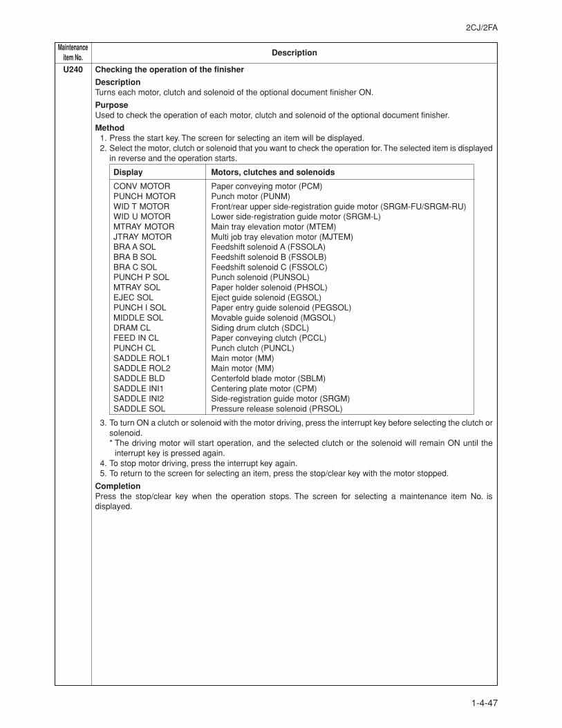
2CJ/2FA
1-4-47
MaintenanceDescriptionitem No.
U240 Checking the operation of the finisher
DescriptionTurns each motor, clutch and solenoid of the optional document finisher ON.
PurposeUsed to check the operation of each motor, clutch and solenoid of the optional document finisher.
Method1. Press the start key. The screen for selecting an item will be displayed.2. Select the motor, clutch or solenoid that you want to check the operation for. The selected item is displayed
in reverse and the operation starts.
Display Motors, clutches and solenoids
CONV MOTOR Paper conveying motor (PCM)PUNCH MOTOR Punch motor (PUNM)WID T MOTOR Front/rear upper side-registration guide motor (SRGM-FU/SRGM-RU)WID U MOTOR Lower side-registration guide motor (SRGM-L)MTRAY MOTOR Main tray elevation motor (MTEM)JTRAY MOTOR Multi job tray elevation motor (MJTEM)BRA A SOL Feedshift solenoid A (FSSOLA)BRA B SOL Feedshift solenoid B (FSSOLB)BRA C SOL Feedshift solenoid C (FSSOLC)PUNCH P SOL Punch solenoid (PUNSOL)MTRAY SOL Paper holder solenoid (PHSOL)EJEC SOL Eject guide solenoid (EGSOL)PUNCH I SOL Paper entry guide solenoid (PEGSOL)MIDDLE SOL Movable guide solenoid (MGSOL)DRAM CL Siding drum clutch (SDCL)FEED IN CL Paper conveying clutch (PCCL)PUNCH CL Punch clutch (PUNCL)SADDLE ROL1 Main motor (MM)SADDLE ROL2 Main motor (MM)SADDLE BLD Centerfold blade motor (SBLM)SADDLE INI1 Centering plate motor (CPM)SADDLE INI2 Side-registration guide motor (SRGM)SADDLE SOL Pressure release solenoid (PRSOL)
3. To turn ON a clutch or solenoid with the motor driving, press the interrupt key before selecting the clutch orsolenoid.* The driving motor will start operation, and the selected clutch or the solenoid will remain ON until the
interrupt key is pressed again.4. To stop motor driving, press the interrupt key again.5. To return to the screen for selecting an item, press the stop/clear key with the motor stopped.
CompletionPress the stop/clear key when the operation stops. The screen for selecting a maintenance item No. isdisplayed.
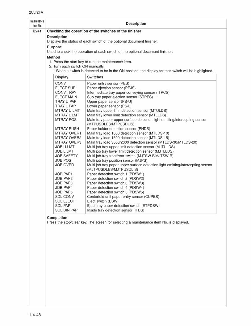
MaintenanceDescriptionitem No.
2CJ/2FA
1-4-48
U241 Checking the operation of the switches of the finisher
DescriptionDisplays the status of each switch of the optional document finisher.
PurposeUsed to check the operation of each switch of the optional document finisher.
Method1. Press the start key to run the maintenance item.2. Turn each switch ON manually.
* When a switch is detected to be in the ON position, the display for that switch will be highlighted.
Display Switches
CONV Paper entry sensor (PES)EJECT SUB Paper ejection sensor (PEJS)CONV TRAY Intermediate tray paper conveying sensor (ITPCS)EJECT MAIN Sub tray paper ejection sensor (STPES)TRAY U PAP Upper paper sensor (PS-U)TRAY L PAP Lower paper sensor (PS-L)MTRAY U LMT Main tray upper limit detection sensor (MTULDS)MTRAY L LMT Main tray lower limit detection sensor (MTLLDS)MTRAY POS Main tray paper upper surface detection light emitting/intercepting sensor
(MTPUSDLES/MTPUSDLIS)MTRAY PUSH Paper holder detection sensor (PHDS)MTRAY OVER1 Main tray load 1000 detection sensor (MTLDS-10)MTRAY OVER2 Main tray load 1500 detection sensor (MTLDS-15)MTRAY OVER3 Main tray load 3000/2000 detection sensor (MTLDS-30/MTLDS-20)JOB U LMT Multi job tray upper limit detection sensor (MJTULDS)JOB L LMT Multi job tray lower limit detection sensor (MJTLLDS)JOB SAFETY Multi job tray front/rear switch (MJTSW-F/MJTSW-R)JOB POS Multi job tray position sensor (MJPS)JOB OVER Multi job tray paper upper surface detection light emitting/intercepting sensor
(MJTPUSDLES/MJTPUSDLIS)JOB PAP1 Paper detection switch 1 (PDSW1)JOB PAP2 Paper detection switch 2 (PDSW2)JOB PAP3 Paper detection switch 3 (PDSW3)JOB PAP4 Paper detection switch 4 (PDSW4)JOB PAP5 Paper detection switch 5 (PDSW5)SDL CONV Centerfold unit paper entry sensor (CUPES)SDL EJECT Eject switch (ESW)SDL PAP Eject tray paper detection switch (ETPDSW)SDL BIN PAP Inside tray detection sensor (ITDS)
CompletionPress the stop/clear key. The screen for selecting a maintenance item No. is displayed.
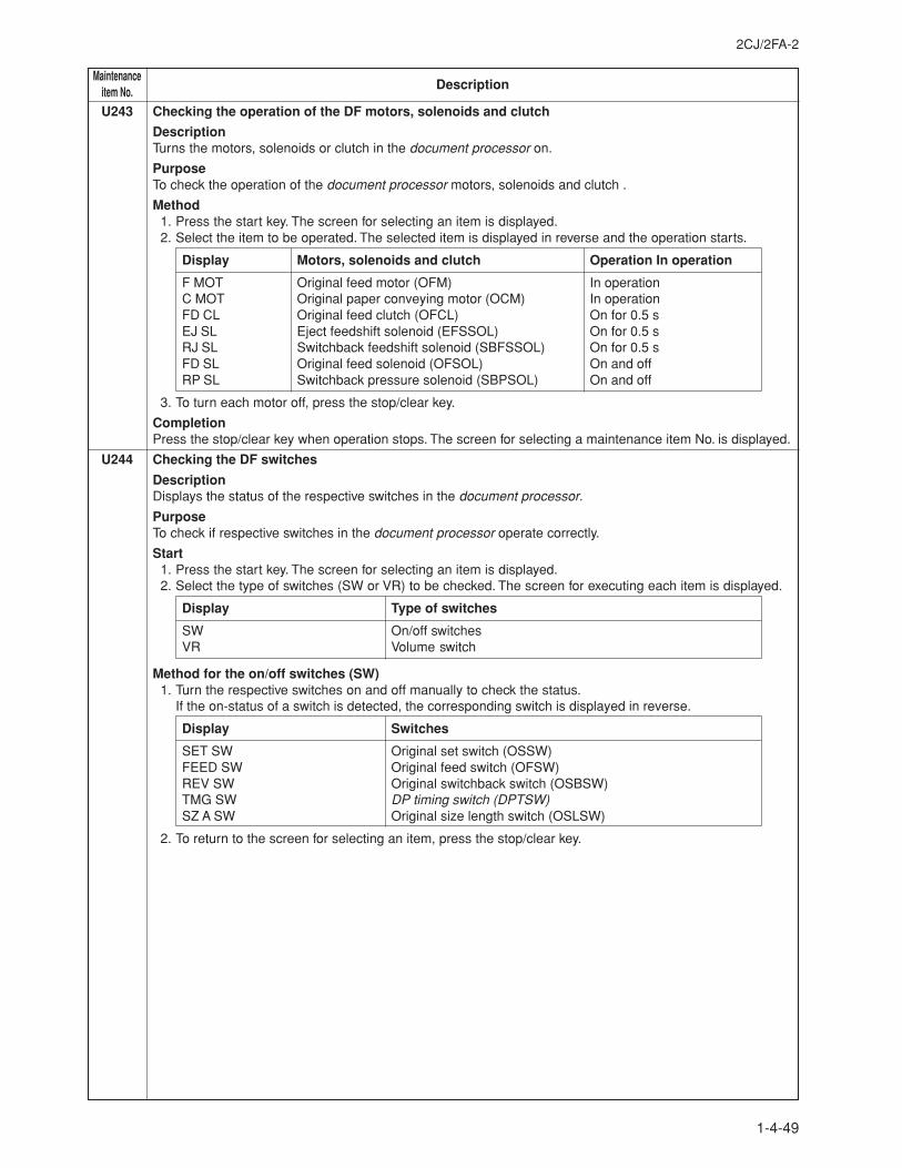
2CJ/2FA-2
1-4-49
MaintenanceDescriptionitem No.
U243 Checking the operation of the DF motors, solenoids and clutch
DescriptionTurns the motors, solenoids or clutch in the document processor on.
PurposeTo check the operation of the document processor motors, solenoids and clutch .
Method1. Press the start key. The screen for selecting an item is displayed.2. Select the item to be operated. The selected item is displayed in reverse and the operation starts.
Display Motors, solenoids and clutch Operation In operation
F MOT Original feed motor (OFM) In operationC MOT Original paper conveying motor (OCM) In operationFD CL Original feed clutch (OFCL) On for 0.5 sEJ SL Eject feedshift solenoid (EFSSOL) On for 0.5 sRJ SL Switchback feedshift solenoid (SBFSSOL) On for 0.5 sFD SL Original feed solenoid (OFSOL) On and offRP SL Switchback pressure solenoid (SBPSOL) On and off
3. To turn each motor off, press the stop/clear key.
CompletionPress the stop/clear key when operation stops. The screen for selecting a maintenance item No. is displayed.
U244 Checking the DF switches
DescriptionDisplays the status of the respective switches in the document processor.
PurposeTo check if respective switches in the document processor operate correctly.
Start1. Press the start key. The screen for selecting an item is displayed.2. Select the type of switches (SW or VR) to be checked. The screen for executing each item is displayed.
Display Type of switches
SW On/off switchesVR Volume switch
Method for the on/off switches (SW)1. Turn the respective switches on and off manually to check the status.
If the on-status of a switch is detected, the corresponding switch is displayed in reverse.
Display Switches
SET SW Original set switch (OSSW)FEED SW Original feed switch (OFSW)REV SW Original switchback switch (OSBSW)TMG SW DP timing switch (DPTSW)SZ A SW Original size length switch (OSLSW)
2. To return to the screen for selecting an item, press the stop/clear key.
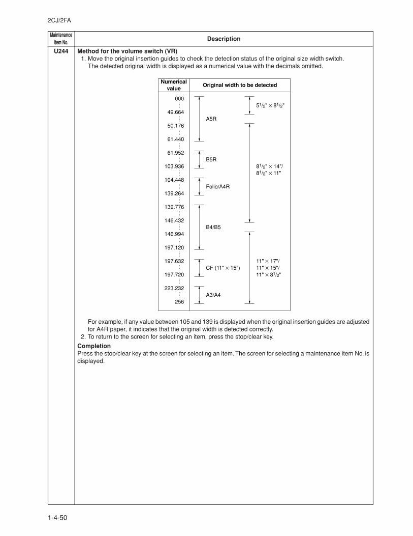
MaintenanceDescriptionitem No.
2CJ/2FA
1-4-50
U244 Method for the volume switch (VR)1. Move the original insertion guides to check the detection status of the original size width switch.
The detected original width is displayed as a numerical value with the decimals omitted.
Numerical value
A5R
B5R
Folio/A4R
B4/B5
CF (11" × 15")
A3/A4
Original width to be detected
51/2" × 81/2"
81/2" × 14"/81/2" × 11"
11" × 17"/11" × 15"/11" × 81/2"
000
49.664
50.176
61.440
61.952
103.936
104.448
139.264
139.776
146.432
146.994
197.120
197.632
197.720
223.232
256
····
····
····
····
····
····
····
····
····
····
····
····
····
····
····
For example, if any value between 105 and 139 is displayed when the original insertion guides are adjustedfor A4R paper, it indicates that the original width is detected correctly.
2. To return to the screen for selecting an item, press the stop/clear key.
CompletionPress the stop/clear key at the screen for selecting an item. The screen for selecting a maintenance item No. isdisplayed.
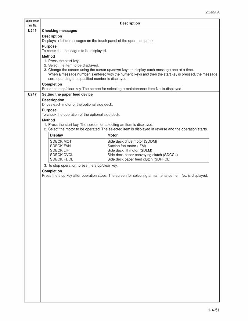
2CJ/2FA
1-4-51
MaintenanceDescriptionitem No.
U245 Checking messages
DescriptionDisplays a list of messages on the touch panel of the operation panel.
PurposeTo check the messages to be displayed.
Method1. Press the start key.2. Select the item to be displayed.3. Change the screen using the cursor up/down keys to display each message one at a time.
When a message number is entered with the numeric keys and then the start key is pressed, the messagecorresponding the specified number is displayed.
CompletionPress the stop/clear key. The screen for selecting a maintenance item No. is displayed.
U247 Setting the paper feed device
DescrioptionDrives each motor of the optional side deck.
PurposeTo check the operation of the optional side deck.
Method1. Press the start key. The screen for selecting an item is displayed.2. Select the motor to be operated. The selected item is displayed in reverse and the operation starts.
Display Motor
SDECK MOT Side deck drive motor (SDDM)SDECK FAN Suction fan motor (IFM)SDECK LIFT Side deck lift motor (SDLM)SDECK CVCL Side deck paper conveying clutch (SDCCL)SDECK FDCL Side deck paper feed clutch (SDPFCL)
3. To stop operation, press the stop/clear key.
CompletionPress the stop key after operation stops. The screen for selecting a maintenance item No. is displayed.
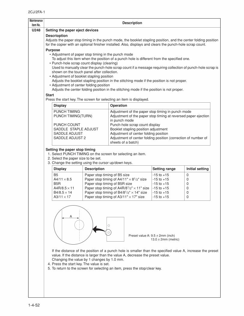
MaintenanceDescriptionitem No.
2CJ/2FA-1
1-4-52
U248 Setting the paper eject devices
DescrioptionAdjusts the paper stop timing in the punch mode, the booklet stapling position, and the center folding positionfor the copier with an optional finisher installed. Also, displays and clears the punch-hole scrap count.
Purpose• Adjustment of paper stop timing in the punch mode
To adjust this item when the position of a punch hole is different from the specified one.• Punch-hole scrap count display (clearing)
Used to manually clear the punch-hole scrap count if a message requiring collection of punch-hole scrap isshown on the touch panel after collection.
• Adjustment of booklet stapling positionAdjusts the booklet stapling position in the stitching mode if the position is not proper.
• Adjustment of center folding positionAdjusts the center folding position in the stitching mode if the position is not proper.
StartPress the start key. The screen for selecting an item is displayed.
Display Operation
PUNCH TIMING Adjustment of the paper stop timing in punch modePUNCH TIMING(TURN) Adjustment of the paper stop timing at reversed paper ejection
in punch modePUNCH COUNT Punch-hole scrap count displaySADDLE STAPLE ADJUST Booklet stapling position adjustmentSADDLE ADJUST Adjustment of center folding positionSADDLE ADJUST 2 Adjustment of center folding position (correction of number of
sheets of a batch)
Setting the paper stop timing1. Select PUNCH TIMING on the screen for selecting an item.2. Select the paper size to be set.3. Change the setting using the cursor up/down keys.
Display Description Setting range Initial setting
B5 Paper stop timing of B5 size -15 to +15 0A4/11 × 8.5 Paper stop timing of A4/11" × 81/2" size -15 to +15 0B5R Paper stop timing of B5R size -15 to +15 0A4R/8.5 × 11 Paper stop timing of A4R/81/2" × 11" size -15 to +15 0B4/8.5 × 14 Paper stop timing of B4/81/2" × 14" size -15 to +15 0A3/11 × 17 Paper stop timing of A3/11" × 17" size -15 to +15 0
If the distance of the position of a punch hole is smaller than the specified value A, increase the presetvalue. If the distance is larger than the value A, decrease the preset value.Changing the value by 1 changes by 1.0 mm.
4. Press the start key. The value is set.5. To return to the screen for selecting an item, press the stop/clear key.
A
Preset value A: 9.5 +_ 2mm (inch) 13.0 +_ 2mm (metric)
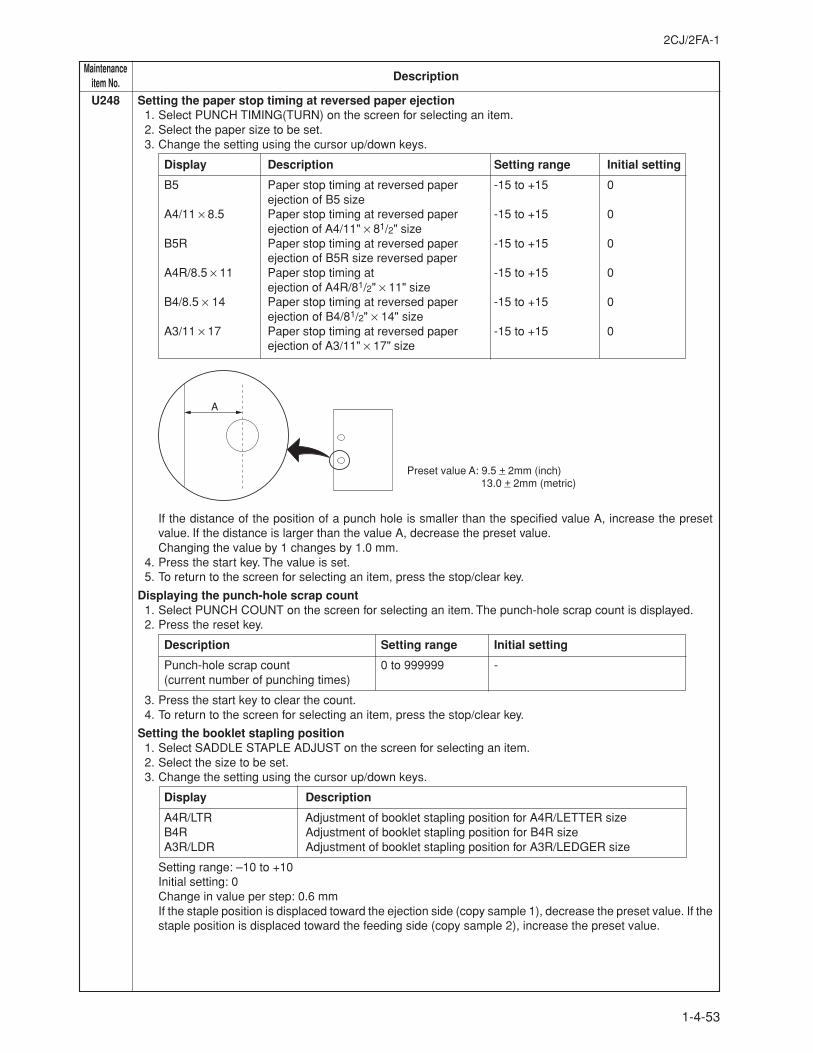
2CJ/2FA-1
1-4-53
MaintenanceDescriptionitem No.
U248 Setting the paper stop timing at reversed paper ejection1. Select PUNCH TIMING(TURN) on the screen for selecting an item.2. Select the paper size to be set.3. Change the setting using the cursor up/down keys.
Display Description Setting range Initial setting
B5 Paper stop timing at reversed paper -15 to +15 0ejection of B5 size
A4/11 × 8.5 Paper stop timing at reversed paper -15 to +15 0ejection of A4/11" × 81/2" size
B5R Paper stop timing at reversed paper -15 to +15 0ejection of B5R size reversed paper
A4R/8.5 × 11 Paper stop timing at -15 to +15 0ejection of A4R/81/2" × 11" size
B4/8.5 × 14 Paper stop timing at reversed paper -15 to +15 0ejection of B4/81/2" × 14" size
A3/11 × 17 Paper stop timing at reversed paper -15 to +15 0ejection of A3/11" × 17" size
If the distance of the position of a punch hole is smaller than the specified value A, increase the presetvalue. If the distance is larger than the value A, decrease the preset value.Changing the value by 1 changes by 1.0 mm.
4. Press the start key. The value is set.5. To return to the screen for selecting an item, press the stop/clear key.
Displaying the punch-hole scrap count1. Select PUNCH COUNT on the screen for selecting an item. The punch-hole scrap count is displayed.2. Press the reset key.
Description Setting range Initial setting
Punch-hole scrap count 0 to 999999 -(current number of punching times)
3. Press the start key to clear the count.4. To return to the screen for selecting an item, press the stop/clear key.
Setting the booklet stapling position1. Select SADDLE STAPLE ADJUST on the screen for selecting an item.2. Select the size to be set.3. Change the setting using the cursor up/down keys.
Display Description
A4R/LTR Adjustment of booklet stapling position for A4R/LETTER sizeB4R Adjustment of booklet stapling position for B4R sizeA3R/LDR Adjustment of booklet stapling position for A3R/LEDGER size
Setting range: –10 to +10Initial setting: 0Change in value per step: 0.6 mmIf the staple position is displaced toward the ejection side (copy sample 1), decrease the preset value. If thestaple position is displaced toward the feeding side (copy sample 2), increase the preset value.
A
Preset value A: 9.5 +_ 2mm (inch) 13.0 +_ 2mm (metric)
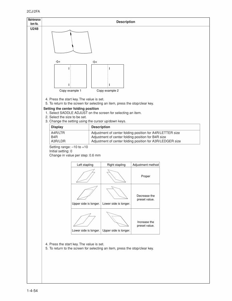
MaintenanceDescriptionitem No.
2CJ/2FA
1-4-54
Left stapling Right stapling Adjustment method
Proper
Decrease the preset value.
Increase the preset value.
Upper side is longer. Lower side is longer.
Lower side is longer. Upper side is longer.
U248
4. Press the start key. The value is set.5. To return to the screen for selecting an item, press the stop/clear key.
Setting the center folding position1. Select SADDLE ADJUST on the screen for selecting an item.2. Select the size to be set.3. Change the setting using the cursor up/down keys.
Display Description
A4R/LTR Adjustment of center folding position for A4R/LETTER sizeB4R Adjustment of center folding position for B4R sizeA3R/LDR Adjustment of center folding position for A3R/LEDGER size
Setting range: –10 to +10Initial setting: 0Change in value per step: 0.6 mm
4. Press the start key. The value is set.5. To return to the screen for selecting an item, press the stop/clear key.
Copy example 1 Copy example 2
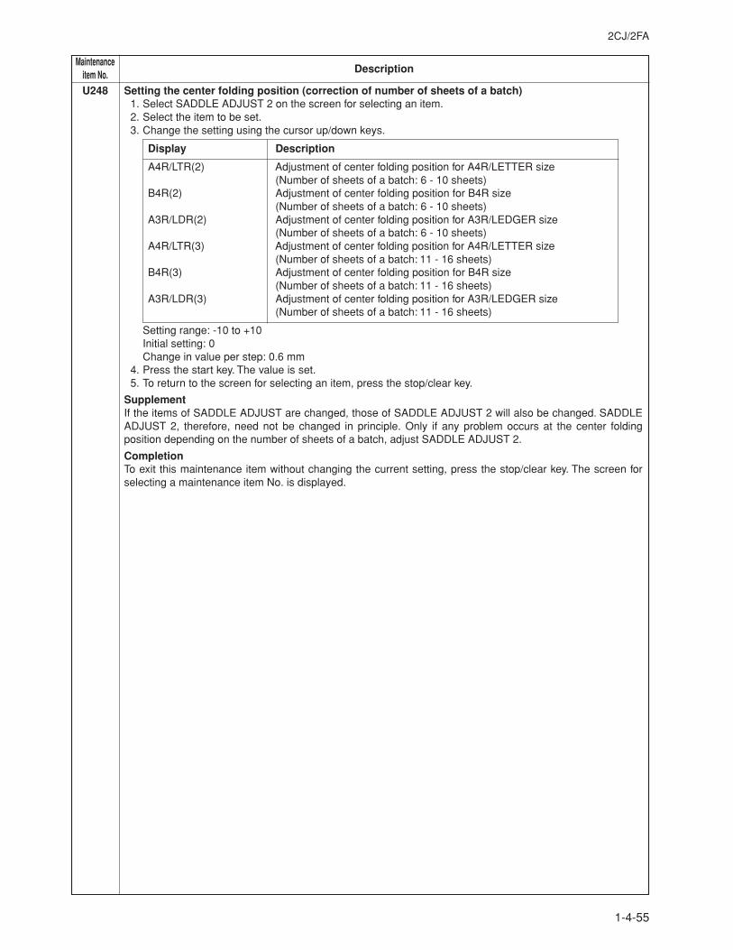
2CJ/2FA
1-4-55
MaintenanceDescriptionitem No.
U248 Setting the center folding position (correction of number of sheets of a batch)1. Select SADDLE ADJUST 2 on the screen for selecting an item.2. Select the item to be set.3. Change the setting using the cursor up/down keys.
Display Description
A4R/LTR(2) Adjustment of center folding position for A4R/LETTER size(Number of sheets of a batch: 6 - 10 sheets)
B4R(2) Adjustment of center folding position for B4R size(Number of sheets of a batch: 6 - 10 sheets)
A3R/LDR(2) Adjustment of center folding position for A3R/LEDGER size(Number of sheets of a batch: 6 - 10 sheets)
A4R/LTR(3) Adjustment of center folding position for A4R/LETTER size(Number of sheets of a batch: 11 - 16 sheets)
B4R(3) Adjustment of center folding position for B4R size(Number of sheets of a batch: 11 - 16 sheets)
A3R/LDR(3) Adjustment of center folding position for A3R/LEDGER size(Number of sheets of a batch: 11 - 16 sheets)
Setting range: -10 to +10Initial setting: 0Change in value per step: 0.6 mm
4. Press the start key. The value is set.5. To return to the screen for selecting an item, press the stop/clear key.
SupplementIf the items of SADDLE ADJUST are changed, those of SADDLE ADJUST 2 will also be changed. SADDLEADJUST 2, therefore, need not be changed in principle. Only if any problem occurs at the center foldingposition depending on the number of sheets of a batch, adjust SADDLE ADJUST 2.
CompletionTo exit this maintenance item without changing the current setting, press the stop/clear key. The screen forselecting a maintenance item No. is displayed.
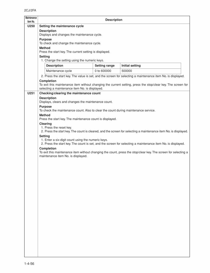
MaintenanceDescriptionitem No.
2CJ/2FA
1-4-56
U250 Setting the maintenance cycle
DescriptionDisplays and changes the maintenance cycle.
PurposeTo check and change the maintenance cycle.
MethodPress the start key. The current setting is displayed.
Setting1. Change the setting using the numeric keys.
Description Setting range Initial setting
Maintenance cycle 0 to 600000 500000
2. Press the start key. The value is set, and the screen for selecting a maintenance item No. is displayed.
CompletionTo exit this maintenance item without changing the current setting, press the stop/clear key. The screen forselecting a maintenance item No. is displayed.
U251 Checking/clearing the maintenance count
DescriptionDisplays, clears and changes the maintenance count.
PurposeTo check the maintenance count. Also to clear the count during maintenance service.
MethodPress the start key. The maintenance count is displayed.
Clearing1. Press the reset key.2. Press the start key. The count is cleared, and the screen for selecting a maintenance item No. is displayed.
Setting1. Enter a six-digit count using the numeric keys.2. Press the start key. The count is set, and the screen for selecting a maintenance item No. is displayed.
CompletionTo exit this maintenance item without changing the count, press the stop/clear key. The screen for selecting amaintenance item No. is displayed.
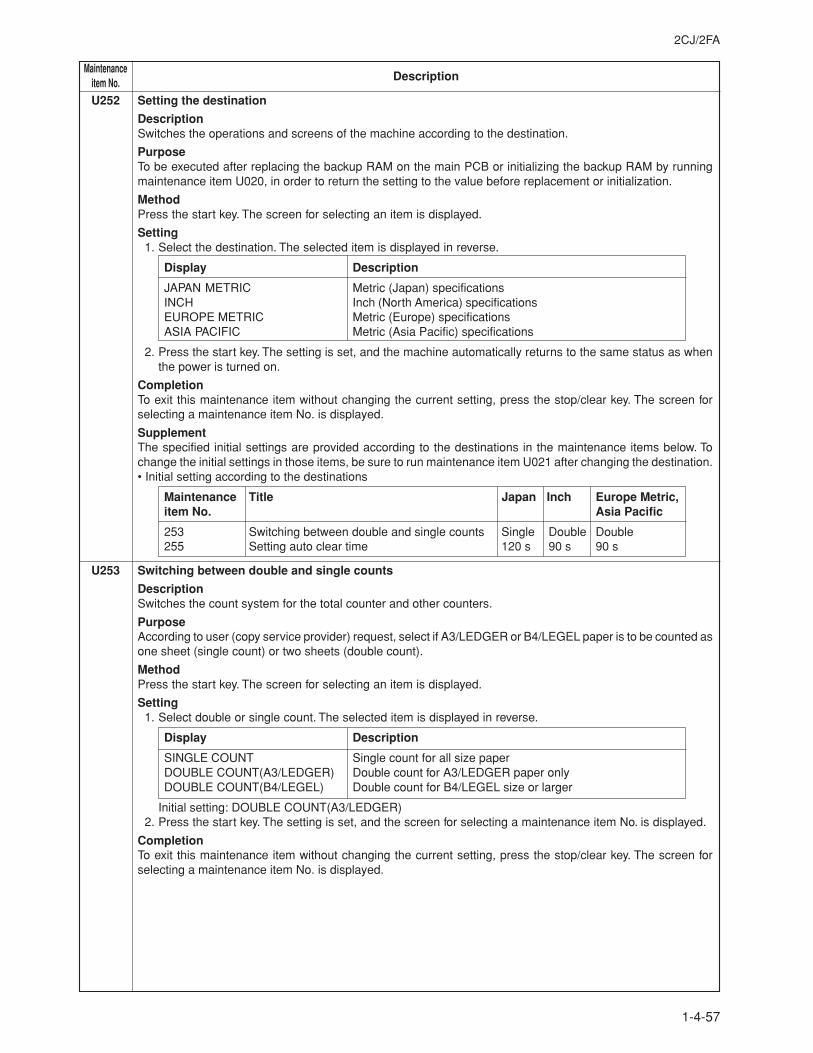
2CJ/2FA
1-4-57
MaintenanceDescriptionitem No.
U252 Setting the destination
DescriptionSwitches the operations and screens of the machine according to the destination.
PurposeTo be executed after replacing the backup RAM on the main PCB or initializing the backup RAM by runningmaintenance item U020, in order to return the setting to the value before replacement or initialization.
MethodPress the start key. The screen for selecting an item is displayed.
Setting1. Select the destination. The selected item is displayed in reverse.
Display Description
JAPAN METRIC Metric (Japan) specificationsINCH Inch (North America) specificationsEUROPE METRIC Metric (Europe) specificationsASIA PACIFIC Metric (Asia Pacific) specifications
2. Press the start key. The setting is set, and the machine automatically returns to the same status as whenthe power is turned on.
CompletionTo exit this maintenance item without changing the current setting, press the stop/clear key. The screen forselecting a maintenance item No. is displayed.
SupplementThe specified initial settings are provided according to the destinations in the maintenance items below. Tochange the initial settings in those items, be sure to run maintenance item U021 after changing the destination.• Initial setting according to the destinations
Maintenance Title Japan Inch Europe Metric,item No. Asia Pacific
253 Switching between double and single counts Single Double Double255 Setting auto clear time 120 s 90 s 90 s
U253 Switching between double and single counts
DescriptionSwitches the count system for the total counter and other counters.
PurposeAccording to user (copy service provider) request, select if A3/LEDGER or B4/LEGEL paper is to be counted asone sheet (single count) or two sheets (double count).
MethodPress the start key. The screen for selecting an item is displayed.
Setting1. Select double or single count. The selected item is displayed in reverse.
Display Description
SINGLE COUNT Single count for all size paperDOUBLE COUNT(A3/LEDGER) Double count for A3/LEDGER paper onlyDOUBLE COUNT(B4/LEGEL) Double count for B4/LEGEL size or larger
Initial setting: DOUBLE COUNT(A3/LEDGER)2. Press the start key. The setting is set, and the screen for selecting a maintenance item No. is displayed.
CompletionTo exit this maintenance item without changing the current setting, press the stop/clear key. The screen forselecting a maintenance item No. is displayed.
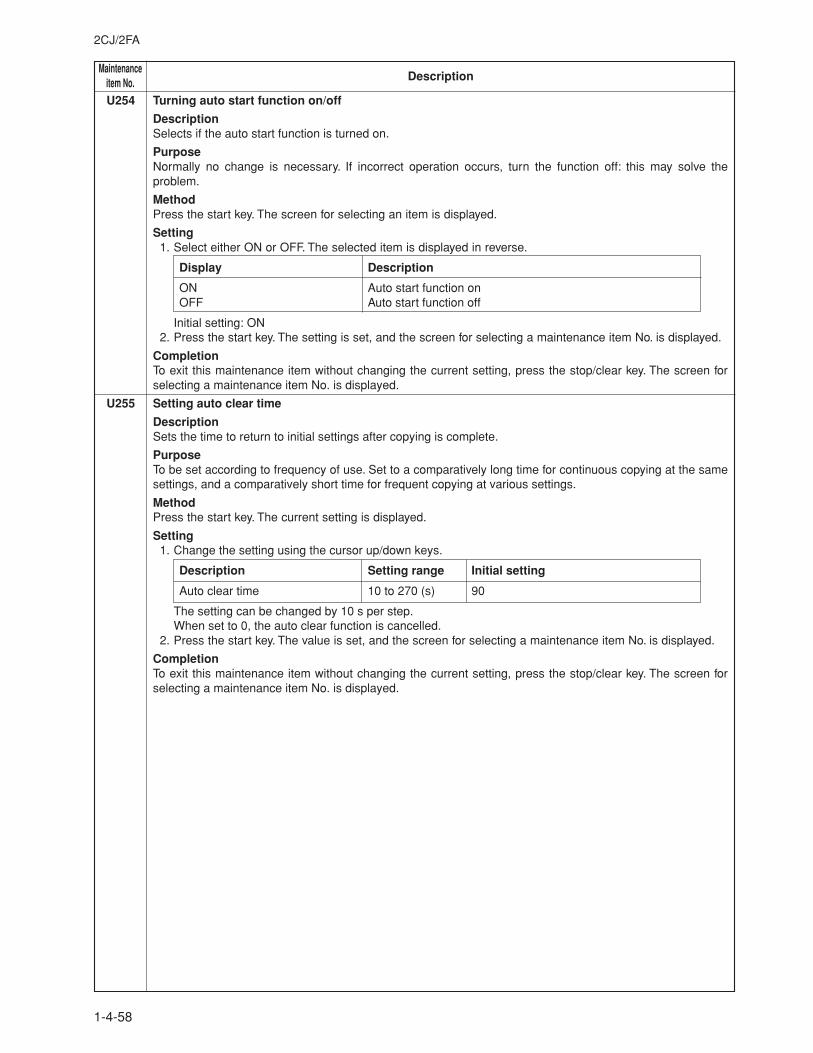
MaintenanceDescriptionitem No.
2CJ/2FA
1-4-58
U254 Turning auto start function on/off
DescriptionSelects if the auto start function is turned on.
PurposeNormally no change is necessary. If incorrect operation occurs, turn the function off: this may solve theproblem.
MethodPress the start key. The screen for selecting an item is displayed.
Setting1. Select either ON or OFF. The selected item is displayed in reverse.
Display Description
ON Auto start function onOFF Auto start function off
Initial setting: ON2. Press the start key. The setting is set, and the screen for selecting a maintenance item No. is displayed.
CompletionTo exit this maintenance item without changing the current setting, press the stop/clear key. The screen forselecting a maintenance item No. is displayed.
U255 Setting auto clear time
DescriptionSets the time to return to initial settings after copying is complete.
PurposeTo be set according to frequency of use. Set to a comparatively long time for continuous copying at the samesettings, and a comparatively short time for frequent copying at various settings.
MethodPress the start key. The current setting is displayed.
Setting1. Change the setting using the cursor up/down keys.
Description Setting range Initial setting
Auto clear time 10 to 270 (s) 90
The setting can be changed by 10 s per step.When set to 0, the auto clear function is cancelled.
2. Press the start key. The value is set, and the screen for selecting a maintenance item No. is displayed.
CompletionTo exit this maintenance item without changing the current setting, press the stop/clear key. The screen forselecting a maintenance item No. is displayed.
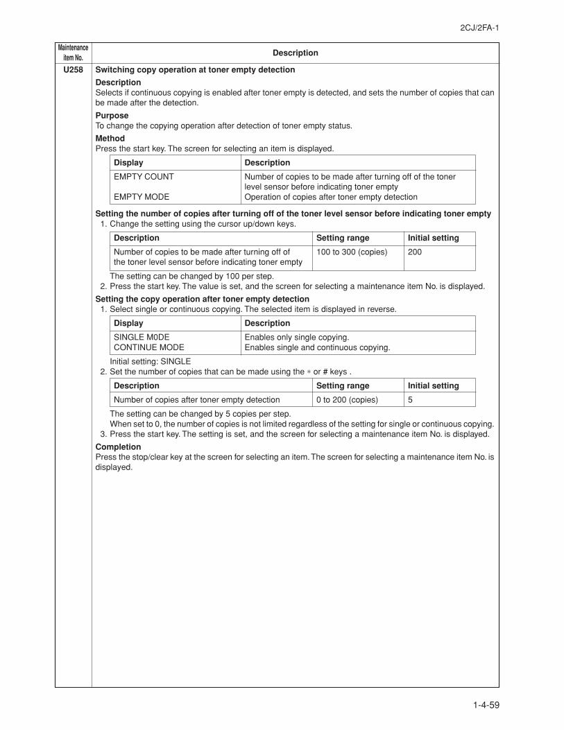
2CJ/2FA-1
1-4-59
MaintenanceDescriptionitem No.
U258 Switching copy operation at toner empty detection
DescriptionSelects if continuous copying is enabled after toner empty is detected, and sets the number of copies that canbe made after the detection.
PurposeTo change the copying operation after detection of toner empty status.
MethodPress the start key. The screen for selecting an item is displayed.
Display Description
EMPTY COUNT Number of copies to be made after turning off of the tonerlevel sensor before indicating toner empty
EMPTY MODE Operation of copies after toner empty detection
Setting the number of copies after turning off of the toner level sensor before indicating toner empty1. Change the setting using the cursor up/down keys.
Description Setting range Initial setting
Number of copies to be made after turning off of 100 to 300 (copies) 200the toner level sensor before indicating toner empty
The setting can be changed by 100 per step.2. Press the start key. The value is set, and the screen for selecting a maintenance item No. is displayed.
Setting the copy operation after toner empty detection1. Select single or continuous copying. The selected item is displayed in reverse.
Display Description
SINGLE M0DE Enables only single copying.CONTINUE MODE Enables single and continuous copying.
Initial setting: SINGLE2. Set the number of copies that can be made using the ∗ or # keys .
Description Setting range Initial setting
Number of copies after toner empty detection 0 to 200 (copies) 5
The setting can be changed by 5 copies per step.When set to 0, the number of copies is not limited regardless of the setting for single or continuous copying.
3. Press the start key. The setting is set, and the screen for selecting a maintenance item No. is displayed.
CompletionPress the stop/clear key at the screen for selecting an item. The screen for selecting a maintenance item No. isdisplayed.
MaintenanceDescriptionitem No.
2CJ/2FA
1-4-60
U260 Changing the copy count timing
DescriptionChanges the copy count timing for the total counter and other counters.
PurposeTo be set according to user (copy service provider) request.If a paper jam occurs frequently in the finisher when the number of copies is counted at the time of paperejection, copies are provided without copy counts. The copy service provider cannot charge for such copying.To prevent this, the copy timing should be made earlier.If a paper jam occurs frequently in the paper conveying or fixing sections when the number of copies is countedbefore the paper reaches those sections, copying is charged without a copy being made. To prevent this, thecopy timing should be made later.
MethodPress the start key. The screen for selecting an item is displayed.
Setting1. Select the copy count timing . The selected item is displayed in reverse.
Display Description
FEED When secondary paper feed startsEJECT When the paper is ejected
Initial setting: EJECT2. Press the start key. The setting is set, and the screen for selecting a maintenance item No. is displayed.
CompletionTo exit this maintenance item without changing the current setting, press the stop/clear key. The screen forselecting a maintenance item No. is displayed.
U263 Setting the paper ejection when copying from the DF
DescriptionSets whether the copies will be ejected in the same or opposite order as the originals when copying from thedocument processor.
PurposeSet according to the preference of the user.
MethodPress the start key. The screen for selecting an item is displayed.
Setting1. Select the ejection order.
Display Setting
FACE-DOWN (NOMAL) Face down ejectionFACE-UP (SPEED) Face up ejection with bitmap copyFACE-UP (MEMORY) Face up ejection with memory copy
Initial setting: FACE-DOWN2. Press the start key. The setting is set, and the screen for selecting a maintenance item No. is displayed.
CompletionTo exit this maintenance item without changing the current setting, press the stop/clear key. The screen forselecting a maintenance item No. is displayed.
2CJ/2FA
1-4-61
MaintenanceDescriptionitem No.
U264 Setting the display order of the date
DescriptionSelects year, month and day as the order of that appears on lists, etc.
PurposeSet according to the user preference.
MethodPress the start key. The screen for selecting an item is displayed.
Setting1. Select the desired order.
Display Setting
YEAR-MONTH-DATE Year/Month/DayMONTH-DATE-YEAR Month/Day/YearDATE-MONTH-YEAR Day/Month/Year
Initial setting: MONTH-DATE-YEAR (for the inch specifications)DATE-MONTH-YEAR (for the metric specifications)
2. Press the start key. The setting is set, and the screen for selecting a maintenance item No. is displayed.
CompletionTo exit this maintenance item without changing the current setting, press the stop/clear key. The screen forselecting a maintenance item No. is displayed.
U265 Setting OEM purchaser code
DescriptionSets the OEM purchaser code.
PurposeSets the code when replacing the main PCB and the like.
MethodPress the start key.
Setting1. Use the numeric keys or cursor up/down keys to adjust the preset value.2. Press the start key. The count is set , and the screen for selecting a maintenance item is displayed.
CompletionTo exit this maintenance item without changing the current setting, press the stop/clear key. The screen forselecting a maintenance item No. is displayed.
MaintenanceDescriptionitem No.
2CJ/2FA
1-4-62
U266 Setting the number of days after which to automatically delete documents
DescrioptionSets the number of days to save documents on the HDD before automatically deleting.
PurposeTo change the number of days to retain data that is saved within the auto-delete area of the HDD beforeautomatically deleting.
MethodPress the start key. The current setting is displayed.
Setting1. Change the setting using the cursor up/down keys.
Description Setting range Initial setting
Number of days after which to automatically delete documents 0 to 7 (days) 7
2. Press the start key. The value is set, and the screen for selecting a maintenance item No. is displayed.
CompletionTo exit this maintenance item without changing the current setting, press the stop/clear key. The screen forselecting a maintenance item No. is displayed.
U275 Setting the number of sheets for duplex circulation
DescrioptionSets the number of sheets for circulation in the duplex copy mode.
PurposeTo reduce the number of sheets for circulation if paper jams occur frequently in the duplex copy mode.
Method1. Press the start key. The screen for selecting an item is displayed.2. Select an item to be set.
Display Description
MODE0 Circulation of five sheetsMODE1 Circulation of four sheets
Initial setting: MODE13. Press the start key. The setting is set, and the screen for selecting a maintenance item No. is displayed.
CompletionTo exit this maintenance item without changing the current setting, press the stop/clear key. The screen forselecting a maintenance item No. is displayed.
U277 Setting auto application change time
DescriptionSets the time that passes until the machine starts automatically printing after completing copying or operationwhen the machine is used as a printer (only if the printer kit is installed).
PurposeAccording to user request, changes the setting.
MethodPress the start key. The current setting is displayed.
Setting1. Change the setting using the cursor up/down keys.
Description Setting range Initial setting
Switching time 30 to 270 (s) 30
The setting can be changed by 30 s per step.2. Press the start key. The value is set, and the screen for selecting a maintenance item No. is displayed.
CompletionTo exit this maintenance item without changing the current setting, press the stop/clear key. The screen forselecting a maintenance item No. is displayed.
2CJ/2FA-2
1-4-63
MaintenanceDescriptionitem No.
U326 Setting the black line cleaning indication
DescriptionSets whether to display the cleaning guidance when detecting the black line.
PurposeDisplays the cleaning guidance in order to make the call for service with the black line decrease by the rubbishon the contact glass when scanning from the document processor.
MethodPress the start key. The screen for selecting an item is displayed.
Setting1. Select ON or OFF.
Display Description
ON Displays the cleaning guidanceOFF Not to display the cleaning guidance
Initial setting: ON2. Press the start key. The setting is set, and the screen for selecting a maintenance item No. is displayed.
CompletionTo exit this maintenance item without changing the current setting, press the stop/clear key. The screen forselecting a maintenance item No. is displayed.
U327 Setting the drawer heater ON/OFF (for 75 cpm only)
Description Sets ON/OFF of the drawer heater.
PurposeAccording to user request, changes the setting.
MethodPress the start key. The screen for selecting an item is displayed.
Setting1. Select ON or OFF. The selected item is displayed in reverse.
Display Description
ON Drawer heater ONOFF Drawer heater OFF
Initial setting: ON2. Press the start key. The setting is set, and the screen for selecting a maintenance item No. is displayed.
CompletionTo exit this maintenance item without changing the current setting, press the stop/clear key. The screen forselecting a maintenance item No. is displayed.
1-4-62-1

2CJ/2FA-2
This page is intentionally left blank.
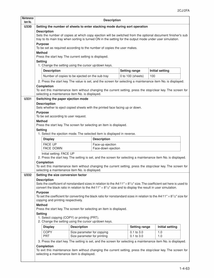
2CJ/2FA
1-4-63
MaintenanceDescriptionitem No.
U330 Setting the number of sheets to enter stacking mode during sort operation
DescriptionSets the number of copies at which copy ejection will be switched from the optional document finisher's subtray to its main tray when sorting is turned ON in the setting for the output mode under user simulation.
PurposeTo be set as required according to the number of copies the user makes.
MethodPress the start key. The current setting is displayed.
Setting1. Change the setting using the cursor up/down keys.
Description Setting range Initial setting
Number of copies to be ejected on the sub tray 0 to 100 (sheets) 100
2. Press the start key. The value is set, and the screen for selecting a maintenance item No. is displayed.
CompletionTo exit this maintenance item without changing the current setting, press the stop/clear key. The screen forselecting a maintenance item No. is displayed.
U331 Switching the paper ejection mode
DescrioptionSets whether to eject copied sheets with the printed face facing up or down.
PurposeTo be set according to user request.
MethodPress the start key. The screen for selecting an item is displayed.
Setting1. Select the ejection mode. The selected item is displayed in reverse.
Display Description
FACE UP Face-up ejectionFACE DOWN Face-down ejection
Initial setting: FACE UP2. Press the start key. The setting is set, and the screen for selecting a maintenance item No. is displayed.
CompletionTo exit this maintenance item without changing the current setting, press the stop/clear key. The screen forselecting a maintenance item No. is displayed.
U332 Setting the size conversion factor
DescriptionSets the coefficient of nonstandard sizes in relation to the A4/11" × 81/2" size. The coefficient set here is used toconvert the black ratio in relation to the A4/11" × 81/2" size and to display the result in user simulation.
PurposeTo set the coefficient for converting the black ratio for nonstandard sizes in relation to the A4/11" × 81/2" size forcopying and printing respectively.
MethodPress the start key. The screen for selecting an item is displayed.
Setting1. Select copying (COPY) or printing (PRT).2. Change the setting using the cursor up/down keys.
Display Description Setting range Initial setting
COPY Size parameter for copying 0.1 to 3.0 1.0PRT Size parameter for printing 0.1 to 3.0 1.0
3. Press the start key. The setting is set, and the screen for selecting a maintenance item No. is displayed.
CompletionTo exit this maintenance item without changing the current setting, press the stop/clear key. The screen forselecting a maintenance item is displayed.
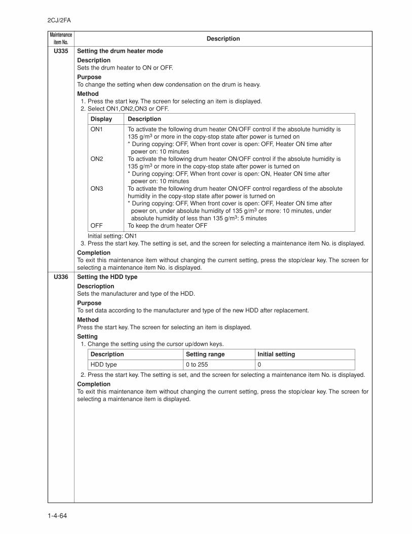
MaintenanceDescriptionitem No.
2CJ/2FA
1-4-64
U335 Setting the drum heater mode
DescriptionSets the drum heater to ON or OFF.
PurposeTo change the setting when dew condensation on the drum is heavy.
Method1. Press the start key. The screen for selecting an item is displayed.2. Select ON1,ON2,ON3 or OFF.
Display Description
ON1 To activate the following drum heater ON/OFF control if the absolute humidity is135 g/m3 or more in the copy-stop state after power is turned on* During copying: OFF, When front cover is open: OFF, Heater ON time after power on: 10 minutes
ON2 To activate the following drum heater ON/OFF control if the absolute humidity is135 g/m3 or more in the copy-stop state after power is turned on* During copying: OFF, When front cover is open: ON, Heater ON time after power on: 10 minutes
ON3 To activate the following drum heater ON/OFF control regardless of the absolutehumidity in the copy-stop state after power is turned on* During copying: OFF, When front cover is open: OFF, Heater ON time after power on, under absolute humidity of 135 g/m3 or more: 10 minutes, under absolute humidity of less than 135 g/m3: 5 minutes
OFF To keep the drum heater OFF
Initial setting: ON13. Press the start key. The setting is set, and the screen for selecting a maintenance item No. is displayed.
CompletionTo exit this maintenance item without changing the current setting, press the stop/clear key. The screen forselecting a maintenance item No. is displayed.
U336 Setting the HDD type
DescrioptionSets the manufacturer and type of the HDD.
PurposeTo set data according to the manufacturer and type of the new HDD after replacement.
MethodPress the start key. The screen for selecting an item is displayed.
Setting1. Change the setting using the cursor up/down keys.
Description Setting range Initial setting
HDD type 0 to 255 0
2. Press the start key. The setting is set, and the screen for selecting a maintenance item No. is displayed.
CompletionTo exit this maintenance item without changing the current setting, press the stop/clear key. The screen forselecting a maintenance item is displayed.
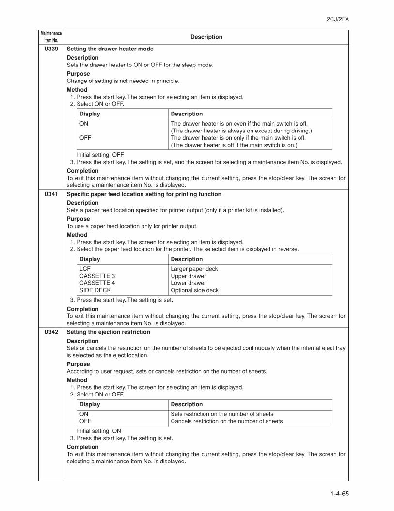
2CJ/2FA
1-4-65
MaintenanceDescriptionitem No.
U339 Setting the drawer heater mode
DescriptionSets the drawer heater to ON or OFF for the sleep mode.
PurposeChange of setting is not needed in principle.
Method1. Press the start key. The screen for selecting an item is displayed.2. Select ON or OFF.
Display Description
ON The drawer heater is on even if the main switch is off.(The drawer heater is always on except during driving.)
OFF The drawer heater is on only if the main switch is off.(The drawer heater is off if the main switch is on.)
Initial setting: OFF3. Press the start key. The setting is set, and the screen for selecting a maintenance item No. is displayed.
CompletionTo exit this maintenance item without changing the current setting, press the stop/clear key. The screen forselecting a maintenance item No. is displayed.
U341 Specific paper feed location setting for printing function
DescriptionSets a paper feed location specified for printer output (only if a printer kit is installed).
PurposeTo use a paper feed location only for printer output.
Method1. Press the start key. The screen for selecting an item is displayed.2. Select the paper feed location for the printer. The selected item is displayed in reverse.
Display Description
LCF Larger paper deckCASSETTE 3 Upper drawerCASSETTE 4 Lower drawerSIDE DECK Optional side deck
3. Press the start key. The setting is set.
CompletionTo exit this maintenance item without changing the current setting, press the stop/clear key. The screen forselecting a maintenance item No. is displayed.
U342 Setting the ejection restriction
DescriptionSets or cancels the restriction on the number of sheets to be ejected continuously when the internal eject trayis selected as the eject location.
PurposeAccording to user request, sets or cancels restriction on the number of sheets.
Method1. Press the start key. The screen for selecting an item is displayed.2. Select ON or OFF.
Display Description
ON Sets restriction on the number of sheetsOFF Cancels restriction on the number of sheets
Initial setting: ON3. Press the start key. The setting is set.
CompletionTo exit this maintenance item without changing the current setting, press the stop/clear key. The screen forselecting a maintenance item No. is displayed.
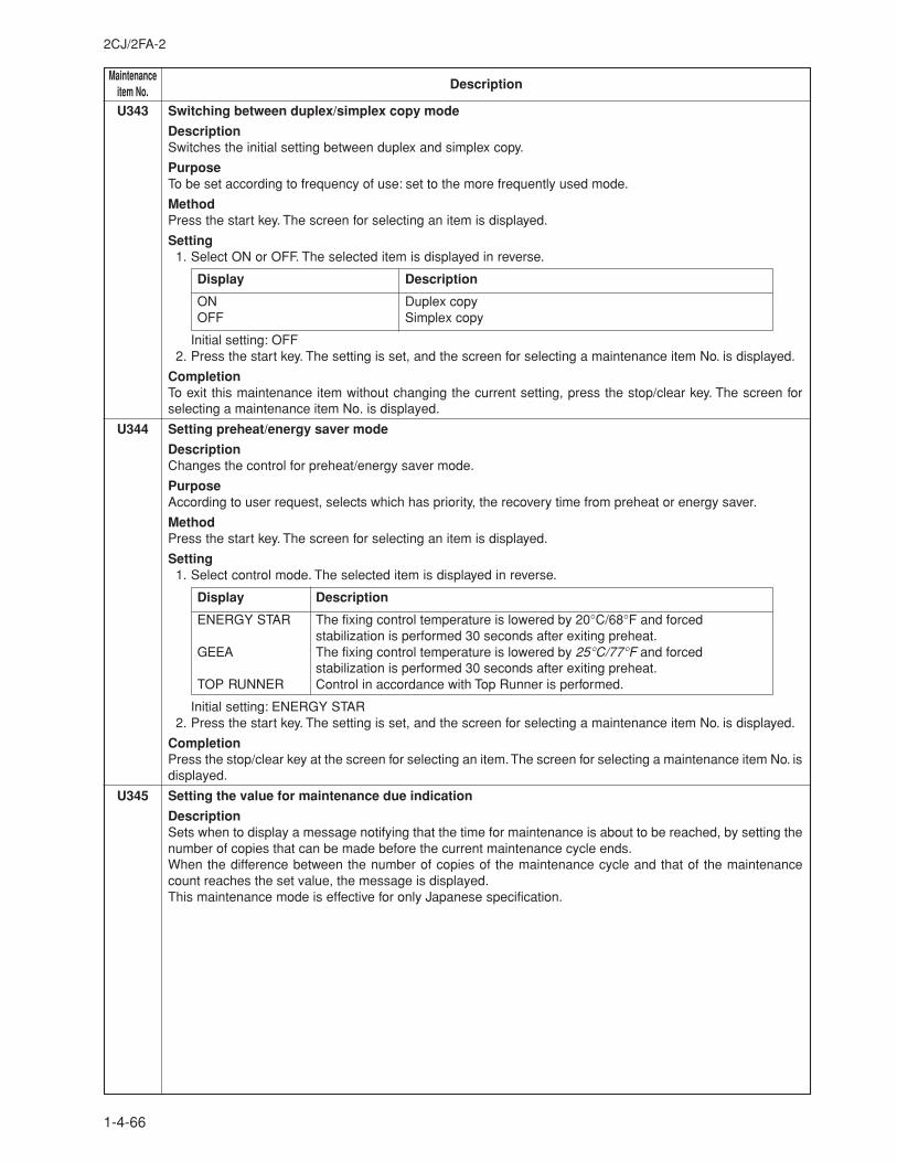
MaintenanceDescriptionitem No.
2CJ/2FA-2
1-4-66
U343 Switching between duplex/simplex copy mode
DescriptionSwitches the initial setting between duplex and simplex copy.
PurposeTo be set according to frequency of use: set to the more frequently used mode.
MethodPress the start key. The screen for selecting an item is displayed.
Setting1. Select ON or OFF. The selected item is displayed in reverse.
Display Description
ON Duplex copyOFF Simplex copy
Initial setting: OFF2. Press the start key. The setting is set, and the screen for selecting a maintenance item No. is displayed.
CompletionTo exit this maintenance item without changing the current setting, press the stop/clear key. The screen forselecting a maintenance item No. is displayed.
U344 Setting preheat/energy saver mode
DescriptionChanges the control for preheat/energy saver mode.
PurposeAccording to user request, selects which has priority, the recovery time from preheat or energy saver.
MethodPress the start key. The screen for selecting an item is displayed.
Setting1. Select control mode. The selected item is displayed in reverse.
Display Description
ENERGY STAR The fixing control temperature is lowered by 20°C/68°F and forcedstabilization is performed 30 seconds after exiting preheat.
GEEA The fixing control temperature is lowered by 25°C/77°F and forcedstabilization is performed 30 seconds after exiting preheat.
TOP RUNNER Control in accordance with Top Runner is performed.
Initial setting: ENERGY STAR2. Press the start key. The setting is set, and the screen for selecting a maintenance item No. is displayed.
CompletionPress the stop/clear key at the screen for selecting an item. The screen for selecting a maintenance item No. isdisplayed.
U345 Setting the value for maintenance due indication
DescriptionSets when to display a message notifying that the time for maintenance is about to be reached, by setting thenumber of copies that can be made before the current maintenance cycle ends.When the difference between the number of copies of the maintenance cycle and that of the maintenancecount reaches the set value, the message is displayed.This maintenance mode is effective for only Japanese specification.
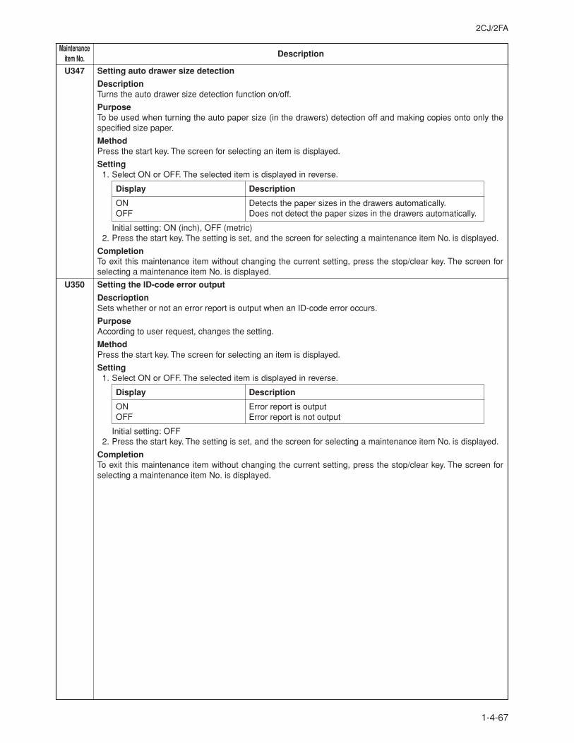
2CJ/2FA
1-4-67
MaintenanceDescriptionitem No.
U347 Setting auto drawer size detection
DescriptionTurns the auto drawer size detection function on/off.
PurposeTo be used when turning the auto paper size (in the drawers) detection off and making copies onto only thespecified size paper.
MethodPress the start key. The screen for selecting an item is displayed.
Setting1. Select ON or OFF. The selected item is displayed in reverse.
Display Description
ON Detects the paper sizes in the drawers automatically.OFF Does not detect the paper sizes in the drawers automatically.
Initial setting: ON (inch), OFF (metric)2. Press the start key. The setting is set, and the screen for selecting a maintenance item No. is displayed.
CompletionTo exit this maintenance item without changing the current setting, press the stop/clear key. The screen forselecting a maintenance item No. is displayed.
U350 Setting the ID-code error output
DescrioptionSets whether or not an error report is output when an ID-code error occurs.
PurposeAccording to user request, changes the setting.
MethodPress the start key. The screen for selecting an item is displayed.
Setting1. Select ON or OFF. The selected item is displayed in reverse.
Display Description
ON Error report is outputOFF Error report is not output
Initial setting: OFF2. Press the start key. The setting is set, and the screen for selecting a maintenance item No. is displayed.
CompletionTo exit this maintenance item without changing the current setting, press the stop/clear key. The screen forselecting a maintenance item No. is displayed.

MaintenanceDescriptionitem No.
2CJ/2FA-1
1-4-68
U355 Setting the output mode for face up output
DescrioptionSpecifies whether to output from the first page so that the pages after the second page are stacked on the firstpage or to output from the last page so that the first page is stacked at the top when outputting face up inprinting.
PurposeSet according to the preference of the user.
MethodPress the start key. The screen for adjustment is displayed.
Setting1. Select The selected item is displayed in reverse.
Display Description
FIRST PRINT To output from the first pageORDER OF PAGE To output from the last page
Initial setting: FIRST PRINT2. Press the start key. The setting is set, and the screen for selecting a maintenance item No. is displayed.
CompletionTo exit this maintenance item without changing the current setting, press the stop/clear key. The screen forselecting a maintenance item No. is displayed.
U402 Adjusting margins of image printing
AdjustmentSee page 1-6-20.
U403 Adjusting margins for scanning an original on the contact glass
AdjustmentSee page 1-6-43.
U404 Adjusting margins for scanning an original from the DF
AdjustmentSee page 1-6-82.
U407 Adjusting the leading edge registration for memory image printing
AdjustmentSee page 1-6-18.
U467 Adjusting the laser output
DescrioptionAdjusts the laser output power.
PurposeUsed when adequate image density cannot be obtained even if "U100 Checking the operation of main highvoltage" is run when the drum is replaced.
MethodPress the start key. The screen for adjustment is displayed.
Setting1. Change the setting using the cursor up/down keys.
Setting range: 130 to 255Initial setting: 230A larger preset value causes dots and lines to be clearly large and thick and the reference density to bedarker.A smaller preset value causes dots and lines to be clearly small and thin and the reference density to belighter.Although two lasers (ADJUST DATA and ADJUST DATA2) can be adjusted separately, be sure to set thesame value. If different values are set, proper images cannot be obtained.
2. Press the start key. The setting is set, and the screen for selecting a maintenance item No. is displayed.
CompletionTo exit this maintenance item without changing the current setting, press the stop/clear key. The screen forselecting a maintenance item No. is displayed.
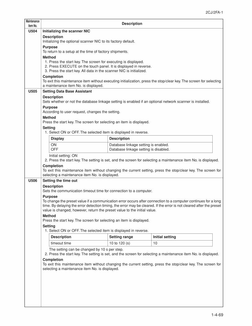
2CJ/2FA-1
1-4-69
MaintenanceDescriptionitem No.
U504 Initializing the scanner NIC
DescriptionInitializing the optional scanner NIC to its factory default.
PurposeTo return to a setup at the time of factory shipments.
Method1. Press the start key. The screen for executing is displayed.2. Press EXECUTE on the touch panel. It is displayed in reverse.3. Press the start key. All data in the scanner NIC is initialized.
CompletionTo exit this maintenance item without executing initialization, press the stop/clear key. The screen for selectinga maintenance item No. is displayed.
U505 Setting Data Base Assistant
DescriptionSets whether or not the database linkage setting is enabled if an optional network scanner is installed.
PurposeAccording to user request, changes the setting.
MethodPress the start key. The screen for selecting an item is displayed.
Setting1. Select ON or OFF. The selected item is displayed in reverse.
Display Description
ON Database linkage setting is enabled.OFF Database linkage setting is disabled.
Initial setting: ON2. Press the start key. The setting is set, and the screen for selecting a maintenance item No. is displayed.
CompletionTo exit this maintenance item without changing the current setting, press the stop/clear key. The screen forselecting a maintenance item No. is displayed.
U506 Setting the time out
DescriptionSets the communication timeout time for connection to a computer.
PurposeTo change the preset value if a communication error occurs after connection to a computer continues for a longtime. By delaying the error detection timing, the error may be cleared. If the error is not cleared after the presetvalue is changed, however, return the preset value to the initial value.
MethodPress the start key. The screen for selecting an item is displayed.
Setting1. Select ON or OFF. The selected item is displayed in reverse.
Description Setting range Initial setting
timeout time 10 to 120 (s) 10
The setting can be changed by 10 s per step.2. Press the start key. The setting is set, and the screen for selecting a maintenance item No. is displayed.
CompletionTo exit this maintenance item without changing the current setting, press the stop/clear key. The screen forselecting a maintenance item No. is displayed.
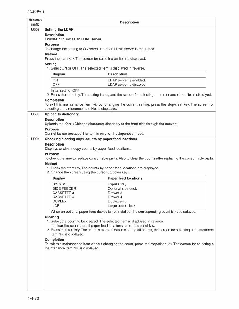
MaintenanceDescriptionitem No.
2CJ/2FA-1
1-4-70
U508 Setting the LDAP
DescriptionEnables or disables an LDAP server.
PurposeTo change the setting to ON when use of an LDAP server is requested.
MethodPress the start key. The screen for selecting an item is displayed.
Setting1. Select ON or OFF. The selected item is displayed in reverse.
Display Description
ON LDAP server is enabled.OFF LDAP server is disabled.
Initial setting: OFF2. Press the start key. The setting is set, and the screen for selecting a maintenance item No. is displayed.
CompletionTo exit this maintenance item without changing the current setting, press the stop/clear key. The screen forselecting a maintenance item No. is displayed.
U509 Upload to dictionary
DescriptionUploads the Kanji (Chinese character) dictionary to the hard disk through the network.
PurposeCannot be run because this item is only for the Japanese mode.
U901 Checking/clearing copy counts by paper feed locations
DescriptionDisplays or clears copy counts by paper feed locations.
PurposeTo check the time to replace consumable parts. Also to clear the counts after replacing the consumable parts.
Method1. Press the start key. The counts by paper feed locations are displayed.2. Change the screen using the cursor up/down keys.
Display Paper feed locations
BYPASS Bypass traySIDE FEEDER Optional side deckCASSETTE 3 Drawer 3CASSETTE 4 Drawer 4DUPLEX Duplex unitLCF Large paper deck
When an optional paper feed device is not installed, the corresponding count is not displayed.
Clearing1. Select the count to be cleared. The selected item is displayed in reverse.
To clear the counts for all paper feed locations, press the reset key.2. Press the start key. The count is cleared. When clearing all counts, the screen for selecting a maintenance
item No. is displayed.
CompletionTo exit this maintenance item without changing the count, press the stop/clear key. The screen for selecting amaintenance item No. is displayed.
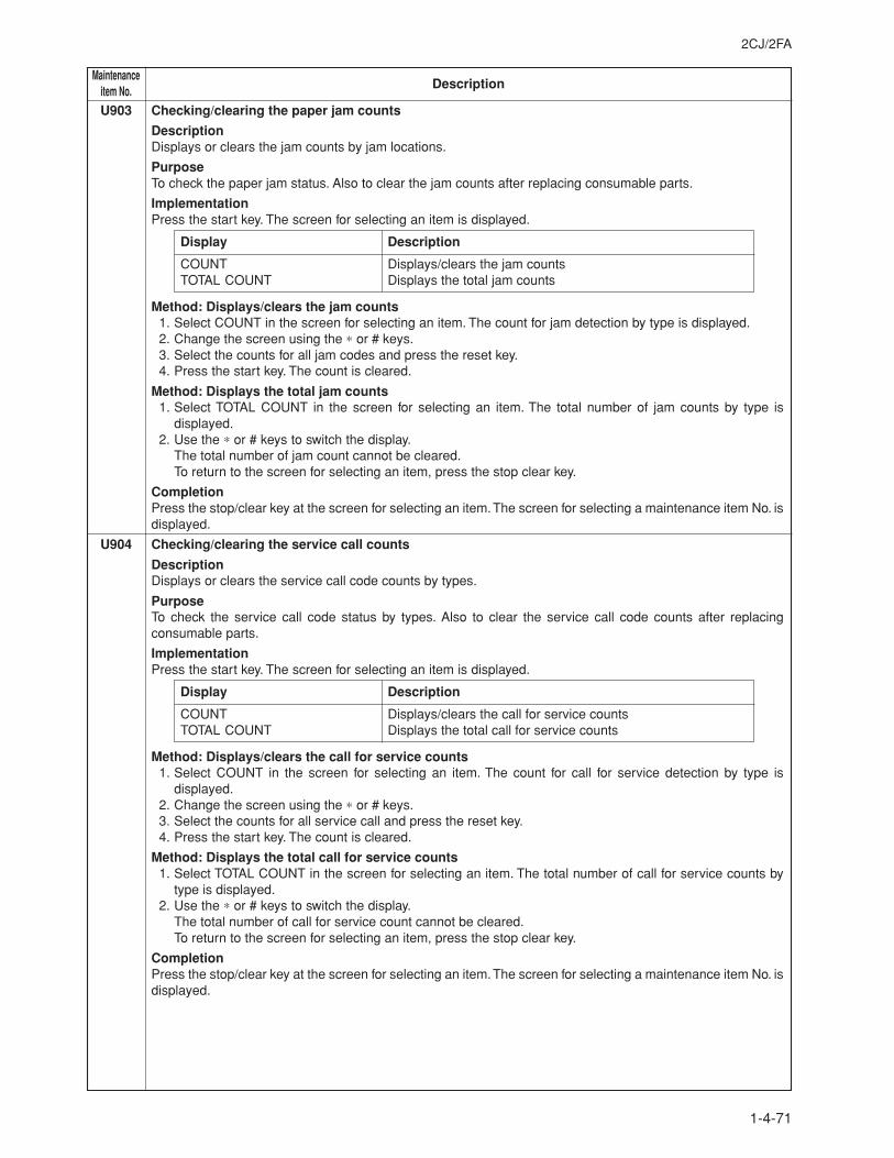
2CJ/2FA
1-4-71
MaintenanceDescriptionitem No.
U903 Checking/clearing the paper jam counts
DescriptionDisplays or clears the jam counts by jam locations.
PurposeTo check the paper jam status. Also to clear the jam counts after replacing consumable parts.
ImplementationPress the start key. The screen for selecting an item is displayed.
Display Description
COUNT Displays/clears the jam countsTOTAL COUNT Displays the total jam counts
Method: Displays/clears the jam counts1. Select COUNT in the screen for selecting an item. The count for jam detection by type is displayed.2. Change the screen using the ∗ or # keys.3. Select the counts for all jam codes and press the reset key.4. Press the start key. The count is cleared.
Method: Displays the total jam counts1. Select TOTAL COUNT in the screen for selecting an item. The total number of jam counts by type is
displayed.2. Use the ∗ or # keys to switch the display.
The total number of jam count cannot be cleared.To return to the screen for selecting an item, press the stop clear key.
CompletionPress the stop/clear key at the screen for selecting an item. The screen for selecting a maintenance item No. isdisplayed.
U904 Checking/clearing the service call counts
DescriptionDisplays or clears the service call code counts by types.
PurposeTo check the service call code status by types. Also to clear the service call code counts after replacingconsumable parts.
ImplementationPress the start key. The screen for selecting an item is displayed.
Display Description
COUNT Displays/clears the call for service countsTOTAL COUNT Displays the total call for service counts
Method: Displays/clears the call for service counts1. Select COUNT in the screen for selecting an item. The count for call for service detection by type is
displayed.2. Change the screen using the ∗ or # keys.3. Select the counts for all service call and press the reset key.4. Press the start key. The count is cleared.
Method: Displays the total call for service counts1. Select TOTAL COUNT in the screen for selecting an item. The total number of call for service counts by
type is displayed.2. Use the ∗ or # keys to switch the display.
The total number of call for service count cannot be cleared.To return to the screen for selecting an item, press the stop clear key.
CompletionPress the stop/clear key at the screen for selecting an item. The screen for selecting a maintenance item No. isdisplayed.
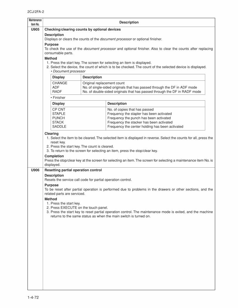
MaintenanceDescriptionitem No.
2CJ/2FA-2
1-4-72
U905 Checking/clearing counts by optional devices
DescriptionDisplays or clears the counts of the document processor or optional finisher.
PurposeTo check the use of the document processor and optional finisher. Also to clear the counts after replacingconsumable parts.
Method1. Press the start key. The screen for selecting an item is displayed.2. Select the device, the count of which is to be checked. The count of the selected device is displayed.
• Document processor
Display Description
CHANGE Original replacement countADF No. of single-sided originals that has passed through the DF in ADF modeRADF No. of double-sided originals that has passed through the DF in RADF mode
• Finisher
Display Description
CP CNT No. of copies that has passedSTAPLE Frequency the stapler has been activatedPUNCH Frequency the punch has been activatedSTACK Frequency the stacker has been activatedSADDLE Frequency the center holding has been activated
Clearing1. Select the item to be cleared. The selected item is displayed in reverse. Select the counts for all, press the
reset key.2. Press the start key. The count is cleared.3. To return to the screen for selecting an item, press the stop/clear key.
CompletionPress the stop/clear key at the screen for selecting an item. The screen for selecting a maintenance item No. isdisplayed.
U906 Resetting partial operation control
DescriptionResets the service call code for partial operation control.
PurposeTo be reset after partial operation is performed due to problems in the drawers or other sections, and therelated parts are serviced.
Method1. Press the start key.2. Press EXECUTE on the touch panel.3. Press the start key to reset partial operation control. The maintenance mode is exited, and the machine
returns to the same status as when the main switch is turned on.
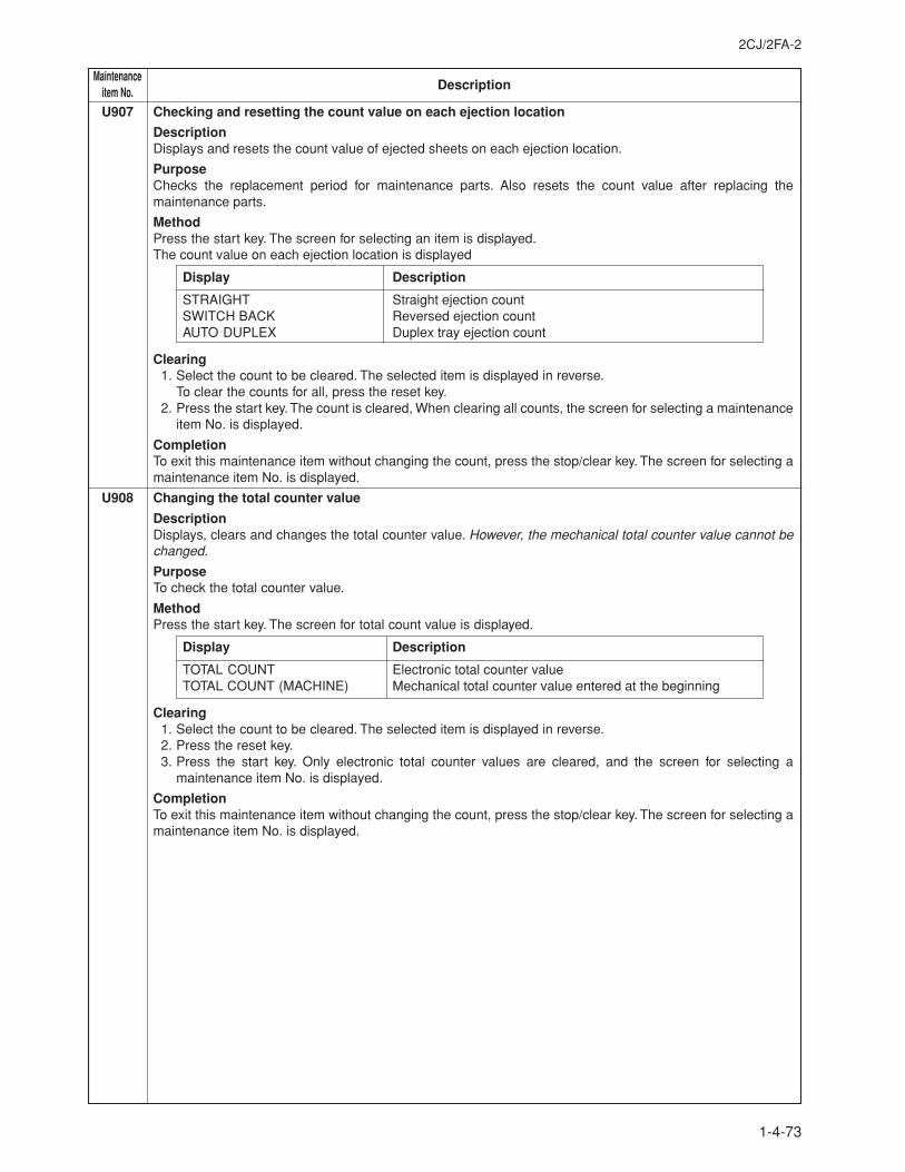
2CJ/2FA-2
1-4-73
MaintenanceDescriptionitem No.
U907 Checking and resetting the count value on each ejection location
DescriptionDisplays and resets the count value of ejected sheets on each ejection location.
PurposeChecks the replacement period for maintenance parts. Also resets the count value after replacing themaintenance parts.
MethodPress the start key. The screen for selecting an item is displayed.The count value on each ejection location is displayed
Display Description
STRAIGHT Straight ejection countSWITCH BACK Reversed ejection countAUTO DUPLEX Duplex tray ejection count
Clearing1. Select the count to be cleared. The selected item is displayed in reverse.
To clear the counts for all, press the reset key.2. Press the start key. The count is cleared, When clearing all counts, the screen for selecting a maintenance
item No. is displayed.
CompletionTo exit this maintenance item without changing the count, press the stop/clear key. The screen for selecting amaintenance item No. is displayed.
U908 Changing the total counter value
DescriptionDisplays, clears and changes the total counter value. However, the mechanical total counter value cannot bechanged.
PurposeTo check the total counter value.
MethodPress the start key. The screen for total count value is displayed.
Display Description
TOTAL COUNT Electronic total counter valueTOTAL COUNT (MACHINE) Mechanical total counter value entered at the beginning
Clearing1. Select the count to be cleared. The selected item is displayed in reverse.2. Press the reset key.3. Press the start key. Only electronic total counter values are cleared, and the screen for selecting a
maintenance item No. is displayed.
CompletionTo exit this maintenance item without changing the count, press the stop/clear key. The screen for selecting amaintenance item No. is displayed.
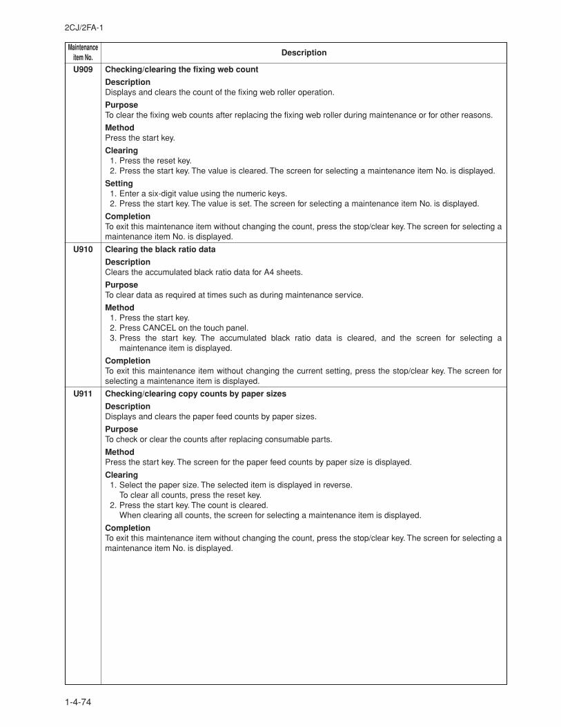
MaintenanceDescriptionitem No.
2CJ/2FA-1
1-4-74
U909 Checking/clearing the fixing web count
DescriptionDisplays and clears the count of the fixing web roller operation.
PurposeTo clear the fixing web counts after replacing the fixing web roller during maintenance or for other reasons.
MethodPress the start key.
Clearing1. Press the reset key.2. Press the start key. The value is cleared. The screen for selecting a maintenance item No. is displayed.
Setting1. Enter a six-digit value using the numeric keys.2. Press the start key. The value is set. The screen for selecting a maintenance item No. is displayed.
CompletionTo exit this maintenance item without changing the count, press the stop/clear key. The screen for selecting amaintenance item No. is displayed.
U910 Clearing the black ratio data
DescriptionClears the accumulated black ratio data for A4 sheets.
PurposeTo clear data as required at times such as during maintenance service.
Method1. Press the start key.2. Press CANCEL on the touch panel.3. Press the start key. The accumulated black ratio data is cleared, and the screen for selecting a
maintenance item is displayed.
CompletionTo exit this maintenance item without changing the current setting, press the stop/clear key. The screen forselecting a maintenance item is displayed.
U911 Checking/clearing copy counts by paper sizes
DescriptionDisplays and clears the paper feed counts by paper sizes.
PurposeTo check or clear the counts after replacing consumable parts.
MethodPress the start key. The screen for the paper feed counts by paper size is displayed.
Clearing1. Select the paper size. The selected item is displayed in reverse.
To clear all counts, press the reset key.2. Press the start key. The count is cleared.
When clearing all counts, the screen for selecting a maintenance item is displayed.
CompletionTo exit this maintenance item without changing the count, press the stop/clear key. The screen for selecting amaintenance item No. is displayed.
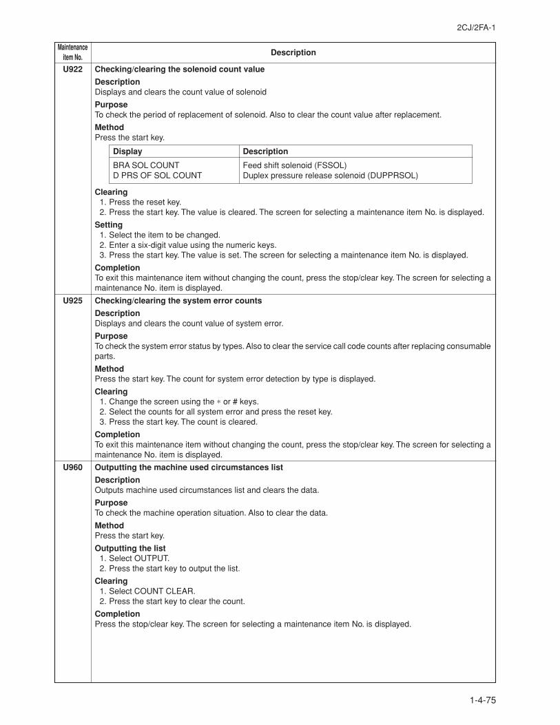
2CJ/2FA-1
1-4-75
MaintenanceDescriptionitem No.
U922 Checking/clearing the solenoid count value
DescriptionDisplays and clears the count value of solenoid
PurposeTo check the period of replacement of solenoid. Also to clear the count value after replacement.
MethodPress the start key.
Display Description
BRA SOL COUNT Feed shift solenoid (FSSOL)D PRS OF SOL COUNT Duplex pressure release solenoid (DUPPRSOL)
Clearing1. Press the reset key.2. Press the start key. The value is cleared. The screen for selecting a maintenance item No. is displayed.
Setting1. Select the item to be changed.2. Enter a six-digit value using the numeric keys.3. Press the start key. The value is set. The screen for selecting a maintenance item No. is displayed.
CompletionTo exit this maintenance item without changing the count, press the stop/clear key. The screen for selecting amaintenance No. item is displayed.
U925 Checking/clearing the system error counts
DescriptionDisplays and clears the count value of system error.
PurposeTo check the system error status by types. Also to clear the service call code counts after replacing consumableparts.
MethodPress the start key. The count for system error detection by type is displayed.
Clearing1. Change the screen using the ∗ or # keys.2. Select the counts for all system error and press the reset key.3. Press the start key. The count is cleared.
CompletionTo exit this maintenance item without changing the count, press the stop/clear key. The screen for selecting amaintenance No. item is displayed.
U960 Outputting the machine used circumstances list
DescriptionOutputs machine used circumstances list and clears the data.
PurposeTo check the machine operation situation. Also to clear the data.
MethodPress the start key.
Outputting the list1. Select OUTPUT.2. Press the start key to output the list.
Clearing1. Select COUNT CLEAR.2. Press the start key to clear the count.
CompletionPress the stop/clear key. The screen for selecting a maintenance item No. is displayed.
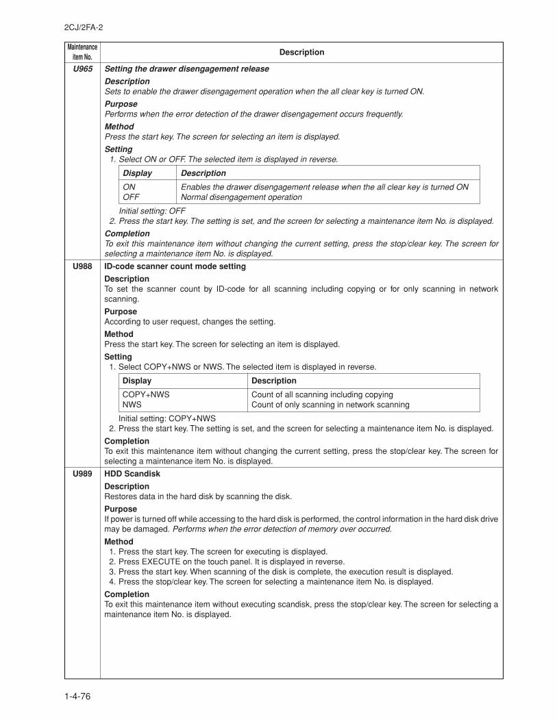
MaintenanceDescriptionitem No.
2CJ/2FA-2
1-4-76
U965 Setting the drawer disengagement release
DescriptionSets to enable the drawer disengagement operation when the all clear key is turned ON.
PurposePerforms when the error detection of the drawer disengagement occurs frequently.
MethodPress the start key. The screen for selecting an item is displayed.
Setting1. Select ON or OFF. The selected item is displayed in reverse.
Display Description
ON Enables the drawer disengagement release when the all clear key is turned ONOFF Normal disengagement operation
Initial setting: OFF2. Press the start key. The setting is set, and the screen for selecting a maintenance item No. is displayed.
CompletionTo exit this maintenance item without changing the current setting, press the stop/clear key. The screen forselecting a maintenance item No. is displayed.
U988 ID-code scanner count mode setting
DescriptionTo set the scanner count by ID-code for all scanning including copying or for only scanning in networkscanning.
PurposeAccording to user request, changes the setting.
MethodPress the start key. The screen for selecting an item is displayed.
Setting1. Select COPY+NWS or NWS. The selected item is displayed in reverse.
Display Description
COPY+NWS Count of all scanning including copyingNWS Count of only scanning in network scanning
Initial setting: COPY+NWS2. Press the start key. The setting is set, and the screen for selecting a maintenance item No. is displayed.
CompletionTo exit this maintenance item without changing the current setting, press the stop/clear key. The screen forselecting a maintenance item No. is displayed.
U989 HDD Scandisk
DescriptionRestores data in the hard disk by scanning the disk.
PurposeIf power is turned off while accessing to the hard disk is performed, the control information in the hard disk drivemay be damaged. Performs when the error detection of memory over occurred.
Method1. Press the start key. The screen for executing is displayed.2. Press EXECUTE on the touch panel. It is displayed in reverse.3. Press the start key. When scanning of the disk is complete, the execution result is displayed.4. Press the stop/clear key. The screen for selecting a maintenance item No. is displayed.
CompletionTo exit this maintenance item without executing scandisk, press the stop/clear key. The screen for selecting amaintenance item No. is displayed.
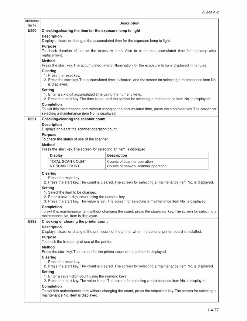
2CJ/2FA-2
1-4-77
MaintenanceDescriptionitem No.
U990 Checking/clearing the time for the exposure lamp to light
DescriptionDisplays, clears or changes the accumulated time for the exposure lamp to light.
PurposeTo check duration of use of the exposure lamp. Also to clear the accumulated time for the lamp afterreplacement.
MethodPress the start key. The accumulated time of illumination for the exposure lamp is displayed in minutes.
Clearing1. Press the reset key.2. Press the start key. The accumulated time is cleared, and the screen for selecting a maintenance item No.
is displayed.
Setting1. Enter a six-digit accumulated time using the numeric keys.2. Press the start key. The time is set, and the screen for selecting a maintenance item No. is displayed.
CompletionTo exit this maintenance item without changing the accumulated time, press the stop/clear key. The screen forselecting a maintenance item No. is displayed.
U991 Checking/clearing the scanner count
DescriptionDisplays or clears the scanner operation count.
PurposeTo check the status of use of the scanner.
MethodPress the start key. The screen for selecting an item is displayed.
Display Description
TOTAL SCAN COUNT Counts of scanner operationNT SCAN COUNT Counts of network scanner operation
Clearing1. Press the reset key.2. Press the start key. The count is cleared. The screen for selecting a maintenance item No. is displayed.
Setting1. Select the item to be changed.2. Enter a seven-digit count using the numeric key.3. Press the start key. The value is set. The screen for selecting a maintenance item No. is displayed.
CompletionTo exit this maintenance item without changing the count, press the stop/clear key. The screen for selecting amaintenance No. item is displayed.
U992 Checking or clearing the printer count
DescriptionDisplays, clears or changes the print count of the printer when the optional printer board is installed.
PurposeTo check the frequency of use of the printer.
MethodPress the start key. The screen for the printer count of the printer is displayed.
Clearing1. Press the reset key.2. Press the start key. The count is cleared. The screen for selecting a maintenance item No. is displayed.
Setting1. Enter a seven-digit count using the numeric keys.2. Press the start key. The value is set. The screen for selecting a maintenance item No. is displayed.
CompletionTo exit this maintenance item without changing the count, press the stop/clear key. The screen for selecting amaintenance No. item is displayed.
2CJ/2FA-2
1-5-1
1-5-1 Paper misfeed detection
(1) Paper misfeed indicationWhen a paper misfeed occurs, the copier immediately stops copying and displays the jam location on the operation panel.Paper misfeed counts sorted by the detection condition can be checked in maintenance item U903.To remove paper jammed in the copier, open the cassette, front cover, upper right cover or lower right cover. When paperis jammed in the document processor, open the DP original reversing cover. To clear a jam in the feedshift and duplex sections,open the ejection cover or draw out the duplex unit.Paper misfeed detection can be reset by opening and closing the respective covers to turn safety switch 1, 2, 3 or 4 off andon.
612
14
3 5
Figure 1-5-1
1 Misfeed in the paper feed section2 Misfeed in the paper conveying section3 Misfeed in the fixing section or the eject section4 Misfeed in the feedshift section or duplex unit5 Misfeed in the document processor6 Misfeed in the optional finisher
2CJ/2FA-2
1-5-2
(2) Paper misfeed detection conditions
LPDPPSENS1
DUPESW
LPDCCLLPDPFCL1
LPDPFCL2
DUPREVCL
DUPFWDCL
DUPJSW
FSSWSBESW
ESW
OFSW OFCL
OSBSW
DPTSW
DUPFSSW
DUPPCSW1
DUPPCSW2
PFSW1
PFSW2
PFSW3
PFSW4
PFSW5
FCL5
FCL4
FCL3
FCL2
PFCL-L
PFCL-U
BYPPSWBYPPFCLFSWFCL1
RSW
LPDPPSENS2LPDPPSENS3
Figure 1-5-2
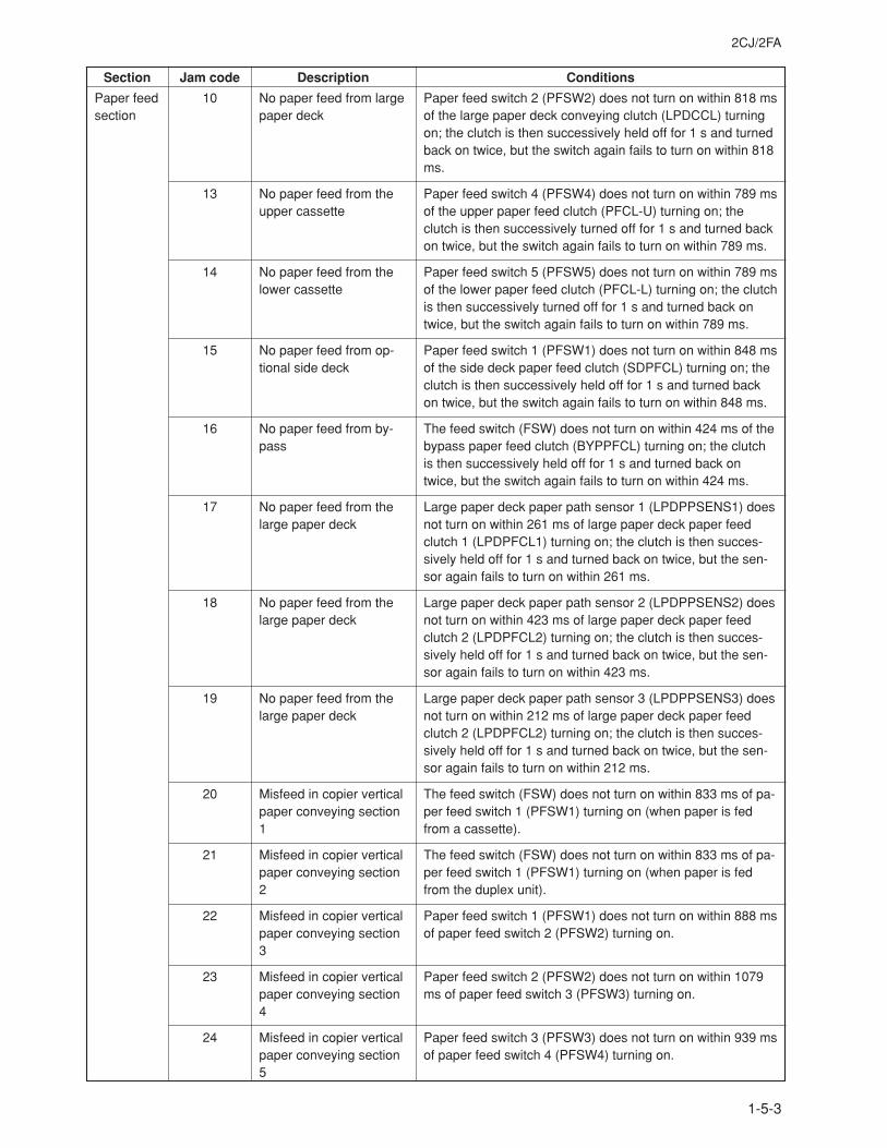
2CJ/2FA
1-5-3
Section Jam code Description Conditions
Paper feedsection
10
13
14
15
16
17
18
19
20
21
22
23
24
No paper feed from largepaper deck
No paper feed from theupper cassette
No paper feed from thelower cassette
No paper feed from op-tional side deck
No paper feed from by-pass
No paper feed from thelarge paper deck
No paper feed from thelarge paper deck
No paper feed from thelarge paper deck
Misfeed in copier verticalpaper conveying section1
Misfeed in copier verticalpaper conveying section2
Misfeed in copier verticalpaper conveying section3
Misfeed in copier verticalpaper conveying section4
Misfeed in copier verticalpaper conveying section5
Paper feed switch 2 (PFSW2) does not turn on within 818 msof the large paper deck conveying clutch (LPDCCL) turningon; the clutch is then successively held off for 1 s and turnedback on twice, but the switch again fails to turn on within 818ms.
Paper feed switch 4 (PFSW4) does not turn on within 789 msof the upper paper feed clutch (PFCL-U) turning on; theclutch is then successively turned off for 1 s and turned backon twice, but the switch again fails to turn on within 789 ms.
Paper feed switch 5 (PFSW5) does not turn on within 789 msof the lower paper feed clutch (PFCL-L) turning on; the clutchis then successively turned off for 1 s and turned back ontwice, but the switch again fails to turn on within 789 ms.
Paper feed switch 1 (PFSW1) does not turn on within 848 msof the side deck paper feed clutch (SDPFCL) turning on; theclutch is then successively held off for 1 s and turned backon twice, but the switch again fails to turn on within 848 ms.
The feed switch (FSW) does not turn on within 424 ms of thebypass paper feed clutch (BYPPFCL) turning on; the clutchis then successively held off for 1 s and turned back ontwice, but the switch again fails to turn on within 424 ms.
Large paper deck paper path sensor 1 (LPDPPSENS1) doesnot turn on within 261 ms of large paper deck paper feedclutch 1 (LPDPFCL1) turning on; the clutch is then succes-sively held off for 1 s and turned back on twice, but the sen-sor again fails to turn on within 261 ms.
Large paper deck paper path sensor 2 (LPDPPSENS2) doesnot turn on within 423 ms of large paper deck paper feedclutch 2 (LPDPFCL2) turning on; the clutch is then succes-sively held off for 1 s and turned back on twice, but the sen-sor again fails to turn on within 423 ms.
Large paper deck paper path sensor 3 (LPDPPSENS3) doesnot turn on within 212 ms of large paper deck paper feedclutch 2 (LPDPFCL2) turning on; the clutch is then succes-sively held off for 1 s and turned back on twice, but the sen-sor again fails to turn on within 212 ms.
The feed switch (FSW) does not turn on within 833 ms of pa-per feed switch 1 (PFSW1) turning on (when paper is fedfrom a cassette).
The feed switch (FSW) does not turn on within 833 ms of pa-per feed switch 1 (PFSW1) turning on (when paper is fedfrom the duplex unit).
Paper feed switch 1 (PFSW1) does not turn on within 888 msof paper feed switch 2 (PFSW2) turning on.
Paper feed switch 2 (PFSW2) does not turn on within 1079ms of paper feed switch 3 (PFSW3) turning on.
Paper feed switch 3 (PFSW3) does not turn on within 939 msof paper feed switch 4 (PFSW4) turning on.
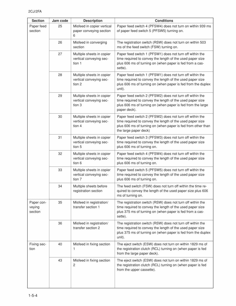
2CJ/2FA
1-5-4
Section Jam code Description Conditions
Paper feedsection
Paper con-veyingsection
Fixing sec-tion
25
26
27
28
29
30
31
32
33
34
35
36
40
43
Misfeed in copier verticalpaper conveying section6
Misfeed in convergingsection
Multiple sheets in copiervertical conveying sec-tion 1
Multiple sheets in copiervertical conveying sec-tion 2
Multiple sheets in copiervertical conveying sec-tion 3
Multiple sheets in copiervertical conveying sec-tion 4
Multiple sheets in copiervertical conveying sec-tion 5
Multiple sheets in copiervertical conveying sec-tion 6
Multiple sheets in copiervertical conveying sec-tion 7
Multiple sheets beforeregistration section
Misfeed in registration/transfer section 1
Misfeed in registration/transfer section 2
Misfeed in fixing section1
Misfeed in fixing section2
Paper feed switch 4 (PFSW4) does not turn on within 939 msof paper feed switch 5 (PFSW5) turning on.
The registration switch (RSW) does not turn on within 503ms of the feed switch (FSW) turning on.
Paper feed switch 1 (PFSW1) does not turn off within thetime required to convey the length of the used paper sizeplus 606 ms of turning on (when paper is fed from a cas-sette).
Paper feed switch 1 (PFSW1) does not turn off within thetime required to convey the length of the used paper sizeplus 606 ms of turning on (when paper is fed from the duplexunit).
Paper feed switch 2 (PFSW2) does not turn off within thetime required to convey the length of the used paper sizeplus 606 ms of turning on (when paper is fed from the largepaper deck).
Paper feed switch 2 (PFSW2) does not turn off within thetime required to convey the length of the used paper sizeplus 606 ms of turning on (when paper is fed from other thanthe large paper deck)
Paper feed switch 3 (PFSW3) does not turn off within thetime required to convey the length of the used paper sizeplus 606 ms of turning on.
Paper feed switch 4 (PFSW4) does not turn off within thetime required to convey the length of the used paper sizeplus 606 ms of turning on.
Paper feed switch 5 (PFSW5) does not turn off within thetime required to convey the length of the used paper sizeplus 606 ms of turning on.
The feed switch (FSW) does not turn off within the time re-quired to convey the length of the used paper size plus 606ms of turning on.
The registration switch (RSW) does not turn off within thetime required to convey the length of the used paper sizeplus 375 ms of turning on (when paper is fed from a cas-sette).
The registration switch (RSW) does not turn off within thetime required to convey the length of the used paper sizeplus 375 ms of turning on (when paper is fed from the duplexunit).
The eject switch (ESW) does not turn on within 1829 ms ofthe registration clutch (RCL) turning on (when paper is fedfrom the large paper deck).
The eject switch (ESW) does not turn on within 1829 ms ofthe registration clutch (RCL) turning on (when paper is fedfrom the upper cassette).
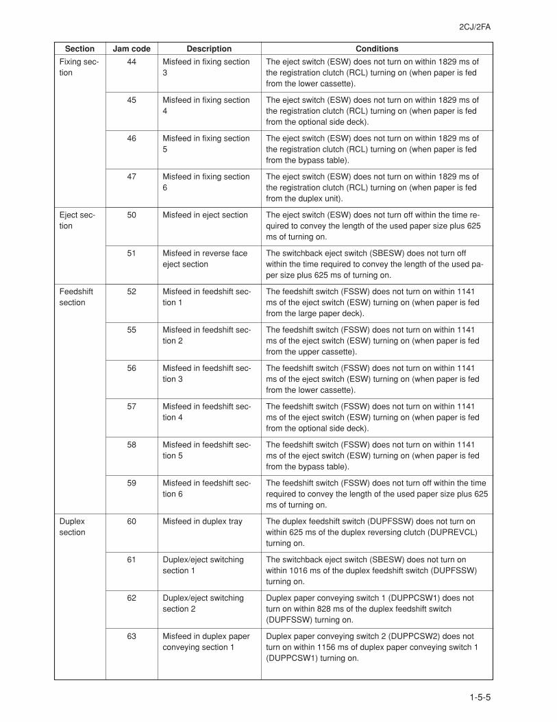
2CJ/2FA
1-5-5
Section Jam code Description Conditions
Fixing sec-tion
Eject sec-tion
Feedshiftsection
Duplexsection
44
45
46
47
50
51
52
55
56
57
58
59
60
61
62
63
Misfeed in fixing section3
Misfeed in fixing section4
Misfeed in fixing section5
Misfeed in fixing section6
Misfeed in eject section
Misfeed in reverse faceeject section
Misfeed in feedshift sec-tion 1
Misfeed in feedshift sec-tion 2
Misfeed in feedshift sec-tion 3
Misfeed in feedshift sec-tion 4
Misfeed in feedshift sec-tion 5
Misfeed in feedshift sec-tion 6
Misfeed in duplex tray
Duplex/eject switchingsection 1
Duplex/eject switchingsection 2
Misfeed in duplex paperconveying section 1
The eject switch (ESW) does not turn on within 1829 ms ofthe registration clutch (RCL) turning on (when paper is fedfrom the lower cassette).
The eject switch (ESW) does not turn on within 1829 ms ofthe registration clutch (RCL) turning on (when paper is fedfrom the optional side deck).
The eject switch (ESW) does not turn on within 1829 ms ofthe registration clutch (RCL) turning on (when paper is fedfrom the bypass table).
The eject switch (ESW) does not turn on within 1829 ms ofthe registration clutch (RCL) turning on (when paper is fedfrom the duplex unit).
The eject switch (ESW) does not turn off within the time re-quired to convey the length of the used paper size plus 625ms of turning on.
The switchback eject switch (SBESW) does not turn offwithin the time required to convey the length of the used pa-per size plus 625 ms of turning on.
The feedshift switch (FSSW) does not turn on within 1141ms of the eject switch (ESW) turning on (when paper is fedfrom the large paper deck).
The feedshift switch (FSSW) does not turn on within 1141ms of the eject switch (ESW) turning on (when paper is fedfrom the upper cassette).
The feedshift switch (FSSW) does not turn on within 1141ms of the eject switch (ESW) turning on (when paper is fedfrom the lower cassette).
The feedshift switch (FSSW) does not turn on within 1141ms of the eject switch (ESW) turning on (when paper is fedfrom the optional side deck).
The feedshift switch (FSSW) does not turn on within 1141ms of the eject switch (ESW) turning on (when paper is fedfrom the bypass table).
The feedshift switch (FSSW) does not turn off within the timerequired to convey the length of the used paper size plus 625ms of turning on.
The duplex feedshift switch (DUPFSSW) does not turn onwithin 625 ms of the duplex reversing clutch (DUPREVCL)turning on.
The switchback eject switch (SBESW) does not turn onwithin 1016 ms of the duplex feedshift switch (DUPFSSW)turning on.
Duplex paper conveying switch 1 (DUPPCSW1) does notturn on within 828 ms of the duplex feedshift switch(DUPFSSW) turning on.
Duplex paper conveying switch 2 (DUPPCSW2) does notturn on within 1156 ms of duplex paper conveying switch 1(DUPPCSW1) turning on.
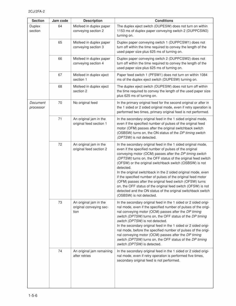
2CJ/2FA-2
1-5-6
Section Jam code Description Conditions
Duplexsection
Documentprocessor
64
65
66
67
68
70
71
72
73
74
Misfeed in duplex paperconveying section 2
Misfeed in duplex paperconveying section 3
Misfeed in duplex paperconveying section 4
Misfeed in duplex ejectsection 1
Misfeed in duplex ejectsection 2
No original feed
An original jam in theoriginal feed section 1
An original jam in theoriginal feed section 2
An original jam in theoriginal conveying sec-tion
An original jam remainingafter retries
The duplex eject switch (DUPESW) does not turn on within1153 ms of duplex paper conveying switch 2 (DUPPCSW2)turning on.
Duplex paper conveying switch 1 (DUPPCSW1) does notturn off within the time required to convey the length of theused paper size plus 625 ms of turning on.
Duplex paper conveying switch 2 (DUPPCSW2) does notturn off within the time required to convey the length of theused paper size plus 625 ms of turning on.
Paper feed switch 1 (PFSW1) does not turn on within 1084ms of the duplex eject switch (DUPESW) turning on.
The duplex eject switch (DUPESW) does not turn off withinthe time required to convey the length of the used paper sizeplus 625 ms of turning on.
In the primary original feed for the second original or after inthe 1 sided or 2 sided original mode, even if retry operation isperformed two times, primary original feed is not performed.
In the secondary original feed in the 1 sided original mode,even if the specified number of pulses of the original feedmotor (OFM) passes after the original switchback switch(OSBSW) turns on, the ON status of the DP timing switch(DPTSW) is not detected.
In the secondary original feed in the 1 sided original mode,even if the specified number of pulses of the originalconveying motor (OCM) passes after the DP timing switch(DPTSW) turns on, the OFF status of the original feed switch(OFSW) or the original switchback switch (OSBSW) is notdetected.In the original switchback in the 2 sided original mode, evenif the specified number of pulses of the original feed motor(OFM) passes after the original feed switch (OFSW) turnson, the OFF status of the original feed switch (OFSW) is notdetected and the ON status of the original switchback switch(OSBSW) is not detected.
In the secondary original feed in the 1 sided or 2 sided origi-nal mode, even if the specified number of pulses of the origi-nal conveying motor (OCM) passes after the DP timingswitch (DPTSW) turns on, the OFF status of the DP timingswitch (DPTSW) is not detected.In the secondary original feed in the 1 sided or 2 sided origi-nal mode, before the specified number of pulses of the origi-nal conveying motor (OCM) passes after the DP timingswitch (DPTSW) turns on, the OFF status of the DP timingswitch (DPTSW) is detected.
In the secondary original feed in the 1 sided or 2 sided origi-nal mode, even if retry operation is performed five times,secondary original feed is not performed.
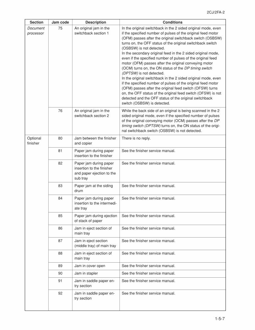
2CJ/2FA-2
1-5-7
Section Jam code Description Conditions
Documentprocessor
Optionalfinisher
75
76
80
81
82
83
84
85
86
87
88
89
90
91
92
An original jam in theswitchback section 1
An original jam in theswitchback section 2
Jam between the finisherand copier
Paper jam during paperinsertion to the finisher
Paper jam during paperinsertion to the finisherand paper ejection to thesub tray
Paper jam at the sidingdrum
Paper jam during paperinsertion to the intermedi-ate tray
Paper jam during ejectionof stack of paper
Jam in eject section ofmain tray
Jam in eject section(middle tray) of main tray
Jam in eject section ofmain tray
Jam in cover open
Jam in stapler
Jam in saddle paper en-try section
Jam in saddle paper en-try section
In the original switchback in the 2 sided original mode, evenif the specified number of pulses of the original feed motor(OFM) passes after the original switchback switch (OSBSW)turns on, the OFF status of the original switchback switch(OSBSW) is not detected.In the secondary original feed in the 2 sided original mode,even if the specified number of pulses of the original feedmotor (OFM) passes after the original conveying motor(OCM) turns on, the ON status of the DP timing switch(DPTSW) is not detected.In the original switchback in the 2 sided original mode, evenif the specified number of pulses of the original feed motor(OFM) passes after the original feed switch (OFSW) turnson, the OFF status of the original feed switch (OFSW) is notdetected and the OFF status of the original switchbackswitch (OSBSW) is detected.
While the back side of an original is being scanned in the 2sided original mode, even if the specified number of pulsesof the original conveying motor (OCM) passes after the DPtiming switch (DPTSW) turns on, the ON status of the origi-nal switchback switch (OSBSW) is not detected.
There is no reply.
See the finisher service manual.
See the finisher service manual.
See the finisher service manual.
See the finisher service manual.
See the finisher service manual.
See the finisher service manual.
See the finisher service manual.
See the finisher service manual.
See the finisher service manual.
See the finisher service manual.
See the finisher service manual.
See the finisher service manual.
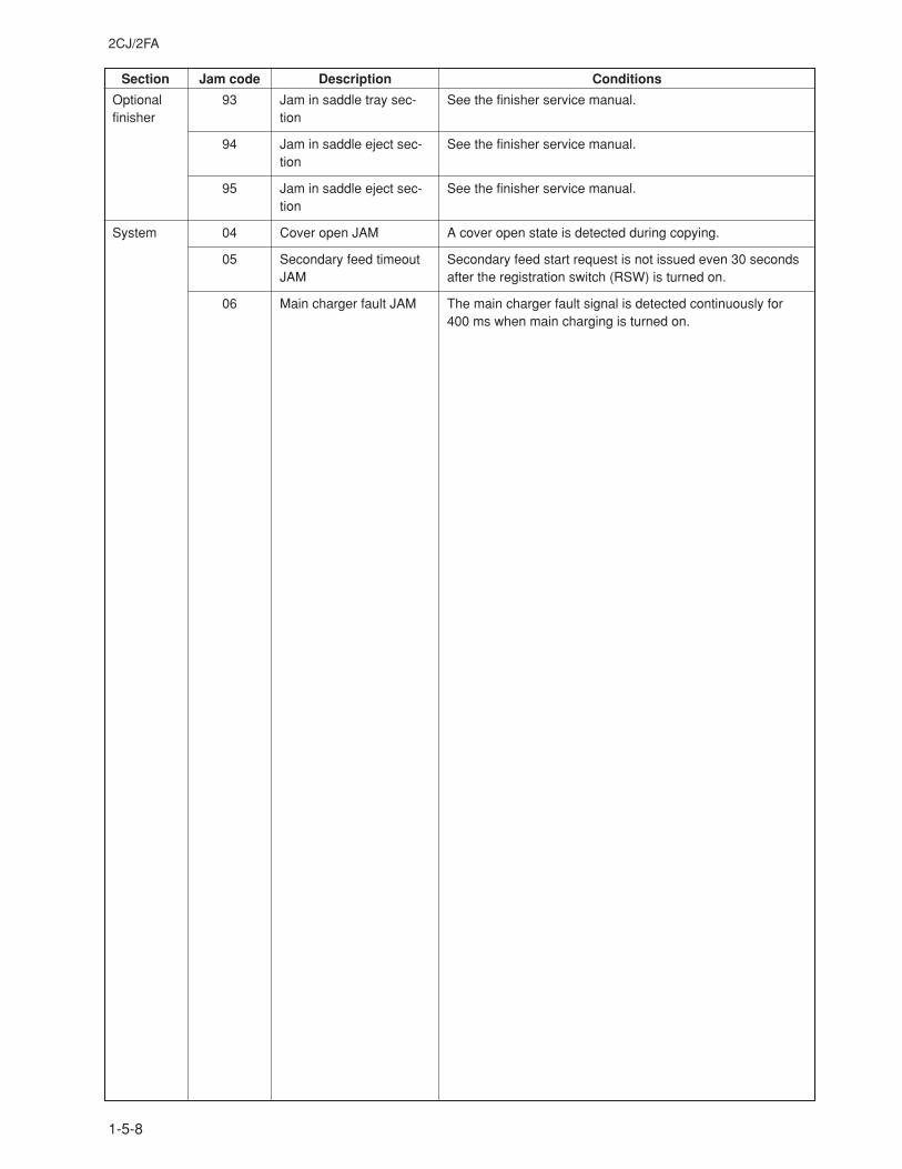
2CJ/2FA
1-5-8
Section Jam code Description Conditions
Optionalfinisher
System
93
94
95
04
05
06
Jam in saddle tray sec-tion
Jam in saddle eject sec-tion
Jam in saddle eject sec-tion
Cover open JAM
Secondary feed timeoutJAM
Main charger fault JAM
See the finisher service manual.
See the finisher service manual.
See the finisher service manual.
A cover open state is detected during copying.
Secondary feed start request is not issued even 30 secondsafter the registration switch (RSW) is turned on.
The main charger fault signal is detected continuously for400 ms when main charging is turned on.
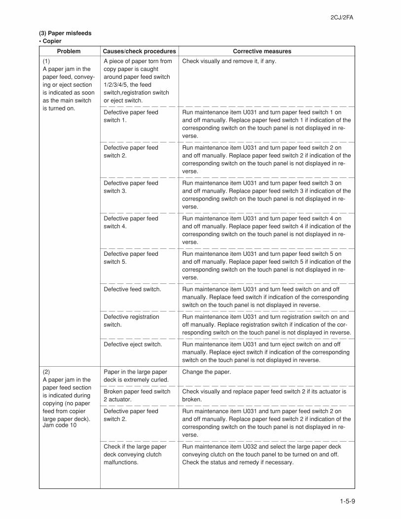
2CJ/2FA
1-5-9
Problem Causes/check procedures Corrective measures
(3) Paper misfeeds• Copier
(1)A paper jam in thepaper feed, convey-ing or eject sectionis indicated as soonas the main switchis turned on.
(2)A paper jam in thepaper feed sectionis indicated duringcopying (no paperfeed from copierlarge paper deck).
A piece of paper torn fromcopy paper is caughtaround paper feed switch1/2/3/4/5, the feedswitch,registration switchor eject switch.
Defective paper feedswitch 1.
Defective paper feedswitch 2.
Defective paper feedswitch 3.
Defective paper feedswitch 4.
Defective paper feedswitch 5.
Defective feed switch.
Defective registrationswitch.
Defective eject switch.
Paper in the large paperdeck is extremely curled.
Broken paper feed switch2 actuator.
Defective paper feedswitch 2.
Check if the large paperdeck conveying clutchmalfunctions.
Check visually and remove it, if any.
Run maintenance item U031 and turn paper feed switch 1 onand off manually. Replace paper feed switch 1 if indication of thecorresponding switch on the touch panel is not displayed in re-verse.
Run maintenance item U031 and turn paper feed switch 2 onand off manually. Replace paper feed switch 2 if indication of thecorresponding switch on the touch panel is not displayed in re-verse.
Run maintenance item U031 and turn paper feed switch 3 onand off manually. Replace paper feed switch 3 if indication of thecorresponding switch on the touch panel is not displayed in re-verse.
Run maintenance item U031 and turn paper feed switch 4 onand off manually. Replace paper feed switch 4 if indication of thecorresponding switch on the touch panel is not displayed in re-verse.
Run maintenance item U031 and turn paper feed switch 5 onand off manually. Replace paper feed switch 5 if indication of thecorresponding switch on the touch panel is not displayed in re-verse.
Run maintenance item U031 and turn feed switch on and offmanually. Replace feed switch if indication of the correspondingswitch on the touch panel is not displayed in reverse.
Run maintenance item U031 and turn registration switch on andoff manually. Replace registration switch if indication of the cor-responding switch on the touch panel is not displayed in reverse.
Run maintenance item U031 and turn eject switch on and offmanually. Replace eject switch if indication of the correspondingswitch on the touch panel is not displayed in reverse.
Change the paper.
Check visually and replace paper feed switch 2 if its actuator isbroken.
Run maintenance item U031 and turn paper feed switch 2 onand off manually. Replace paper feed switch 2 if indication of thecorresponding switch on the touch panel is not displayed in re-verse.
Run maintenance item U032 and select the large paper deckconveying clutch on the touch panel to be turned on and off.Check the status and remedy if necessary.
Jam code 10
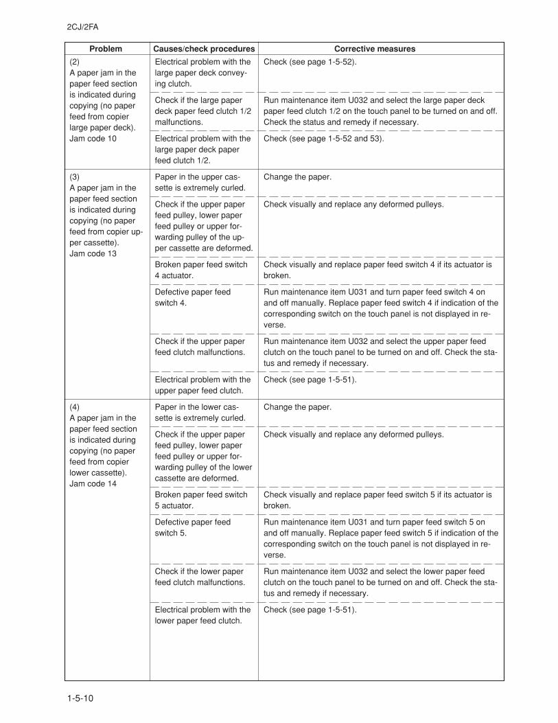
2CJ/2FA
1-5-10
Problem Causes/check procedures Corrective measures
(2)A paper jam in thepaper feed sectionis indicated duringcopying (no paperfeed from copierlarge paper deck).Jam code 10
(3)A paper jam in thepaper feed sectionis indicated duringcopying (no paperfeed from copier up-per cassette).Jam code 13
(4)A paper jam in thepaper feed sectionis indicated duringcopying (no paperfeed from copierlower cassette).Jam code 14
Electrical problem with thelarge paper deck convey-ing clutch.
Check if the large paperdeck paper feed clutch 1/2malfunctions.
Electrical problem with thelarge paper deck paperfeed clutch 1/2.
Paper in the upper cas-sette is extremely curled.
Check if the upper paperfeed pulley, lower paperfeed pulley or upper for-warding pulley of the up-per cassette are deformed.
Broken paper feed switch4 actuator.
Defective paper feedswitch 4.
Check if the upper paperfeed clutch malfunctions.
Electrical problem with theupper paper feed clutch.
Paper in the lower cas-sette is extremely curled.
Check if the upper paperfeed pulley, lower paperfeed pulley or upper for-warding pulley of the lowercassette are deformed.
Broken paper feed switch5 actuator.
Defective paper feedswitch 5.
Check if the lower paperfeed clutch malfunctions.
Electrical problem with thelower paper feed clutch.
Check (see page 1-5-52).
Run maintenance item U032 and select the large paper deckpaper feed clutch 1/2 on the touch panel to be turned on and off.Check the status and remedy if necessary.
Check (see page 1-5-52 and 53).
Change the paper.
Check visually and replace any deformed pulleys.
Check visually and replace paper feed switch 4 if its actuator isbroken.
Run maintenance item U031 and turn paper feed switch 4 onand off manually. Replace paper feed switch 4 if indication of thecorresponding switch on the touch panel is not displayed in re-verse.
Run maintenance item U032 and select the upper paper feedclutch on the touch panel to be turned on and off. Check the sta-tus and remedy if necessary.
Check (see page 1-5-51).
Change the paper.
Check visually and replace any deformed pulleys.
Check visually and replace paper feed switch 5 if its actuator isbroken.
Run maintenance item U031 and turn paper feed switch 5 onand off manually. Replace paper feed switch 5 if indication of thecorresponding switch on the touch panel is not displayed in re-verse.
Run maintenance item U032 and select the lower paper feedclutch on the touch panel to be turned on and off. Check the sta-tus and remedy if necessary.
Check (see page 1-5-51).
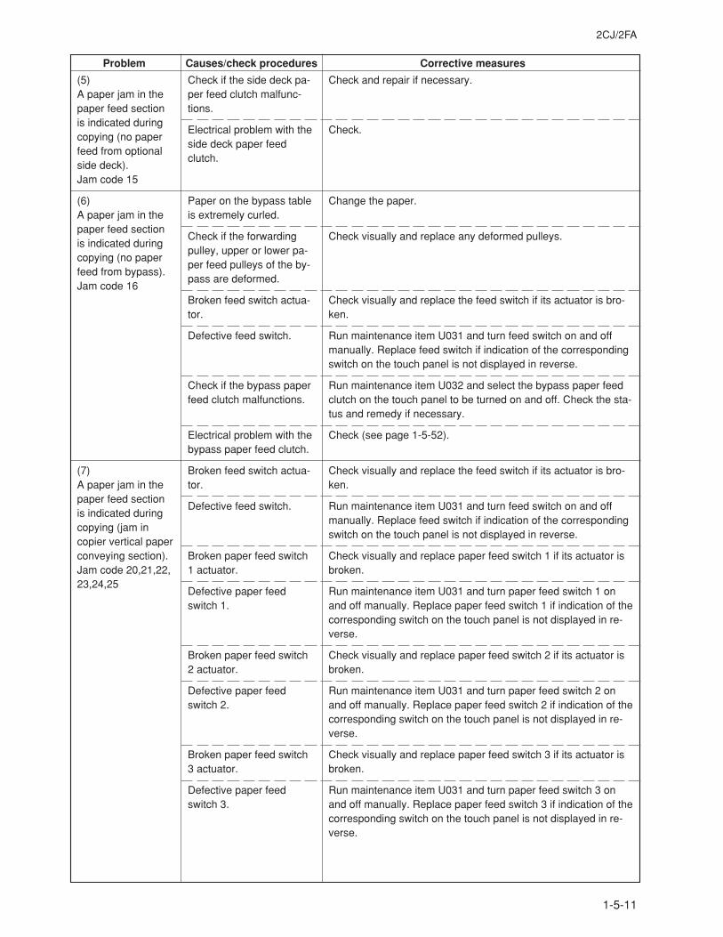
2CJ/2FA
1-5-11
Problem Causes/check procedures Corrective measures
(5)A paper jam in thepaper feed sectionis indicated duringcopying (no paperfeed from optionalside deck).Jam code 15
(6)A paper jam in thepaper feed sectionis indicated duringcopying (no paperfeed from bypass).Jam code 16
(7)A paper jam in thepaper feed sectionis indicated duringcopying (jam incopier vertical paperconveying section).Jam code 20,21,22,23,24,25
Check if the side deck pa-per feed clutch malfunc-tions.
Electrical problem with theside deck paper feedclutch.
Paper on the bypass tableis extremely curled.
Check if the forwardingpulley, upper or lower pa-per feed pulleys of the by-pass are deformed.
Broken feed switch actua-tor.
Defective feed switch.
Check if the bypass paperfeed clutch malfunctions.
Electrical problem with thebypass paper feed clutch.
Broken feed switch actua-tor.
Defective feed switch.
Broken paper feed switch1 actuator.
Defective paper feedswitch 1.
Broken paper feed switch2 actuator.
Defective paper feedswitch 2.
Broken paper feed switch3 actuator.
Defective paper feedswitch 3.
Check and repair if necessary.
Check.
Change the paper.
Check visually and replace any deformed pulleys.
Check visually and replace the feed switch if its actuator is bro-ken.
Run maintenance item U031 and turn feed switch on and offmanually. Replace feed switch if indication of the correspondingswitch on the touch panel is not displayed in reverse.
Run maintenance item U032 and select the bypass paper feedclutch on the touch panel to be turned on and off. Check the sta-tus and remedy if necessary.
Check (see page 1-5-52).
Check visually and replace the feed switch if its actuator is bro-ken.
Run maintenance item U031 and turn feed switch on and offmanually. Replace feed switch if indication of the correspondingswitch on the touch panel is not displayed in reverse.
Check visually and replace paper feed switch 1 if its actuator isbroken.
Run maintenance item U031 and turn paper feed switch 1 onand off manually. Replace paper feed switch 1 if indication of thecorresponding switch on the touch panel is not displayed in re-verse.
Check visually and replace paper feed switch 2 if its actuator isbroken.
Run maintenance item U031 and turn paper feed switch 2 onand off manually. Replace paper feed switch 2 if indication of thecorresponding switch on the touch panel is not displayed in re-verse.
Check visually and replace paper feed switch 3 if its actuator isbroken.
Run maintenance item U031 and turn paper feed switch 3 onand off manually. Replace paper feed switch 3 if indication of thecorresponding switch on the touch panel is not displayed in re-verse.
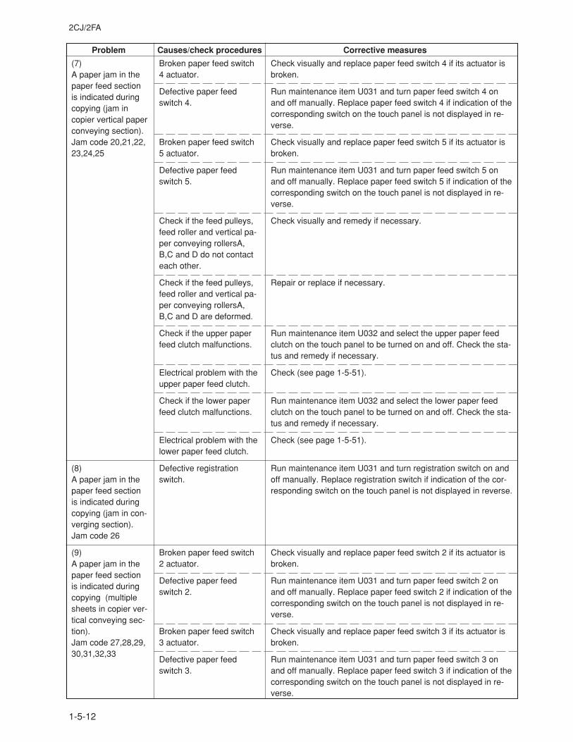
2CJ/2FA
1-5-12
Problem Causes/check procedures Corrective measures
(7)A paper jam in thepaper feed sectionis indicated duringcopying (jam incopier vertical paperconveying section).Jam code 20,21,22,23,24,25
(8)A paper jam in thepaper feed sectionis indicated duringcopying (jam in con-verging section).Jam code 26
(9)A paper jam in thepaper feed sectionis indicated duringcopying (multiplesheets in copier ver-tical conveying sec-tion).Jam code 27,28,29,30,31,32,33
Broken paper feed switch4 actuator.
Defective paper feedswitch 4.
Broken paper feed switch5 actuator.
Defective paper feedswitch 5.
Check if the feed pulleys,feed roller and vertical pa-per conveying rollersA,B,C and D do not contacteach other.
Check if the feed pulleys,feed roller and vertical pa-per conveying rollersA,B,C and D are deformed.
Check if the upper paperfeed clutch malfunctions.
Electrical problem with theupper paper feed clutch.
Check if the lower paperfeed clutch malfunctions.
Electrical problem with thelower paper feed clutch.
Defective registrationswitch.
Broken paper feed switch2 actuator.
Defective paper feedswitch 2.
Broken paper feed switch3 actuator.
Defective paper feedswitch 3.
Check visually and replace paper feed switch 4 if its actuator isbroken.
Run maintenance item U031 and turn paper feed switch 4 onand off manually. Replace paper feed switch 4 if indication of thecorresponding switch on the touch panel is not displayed in re-verse.
Check visually and replace paper feed switch 5 if its actuator isbroken.
Run maintenance item U031 and turn paper feed switch 5 onand off manually. Replace paper feed switch 5 if indication of thecorresponding switch on the touch panel is not displayed in re-verse.
Check visually and remedy if necessary.
Repair or replace if necessary.
Run maintenance item U032 and select the upper paper feedclutch on the touch panel to be turned on and off. Check the sta-tus and remedy if necessary.
Check (see page 1-5-51).
Run maintenance item U032 and select the lower paper feedclutch on the touch panel to be turned on and off. Check the sta-tus and remedy if necessary.
Check (see page 1-5-51).
Run maintenance item U031 and turn registration switch on andoff manually. Replace registration switch if indication of the cor-responding switch on the touch panel is not displayed in reverse.
Check visually and replace paper feed switch 2 if its actuator isbroken.
Run maintenance item U031 and turn paper feed switch 2 onand off manually. Replace paper feed switch 2 if indication of thecorresponding switch on the touch panel is not displayed in re-verse.
Check visually and replace paper feed switch 3 if its actuator isbroken.
Run maintenance item U031 and turn paper feed switch 3 onand off manually. Replace paper feed switch 3 if indication of thecorresponding switch on the touch panel is not displayed in re-verse.
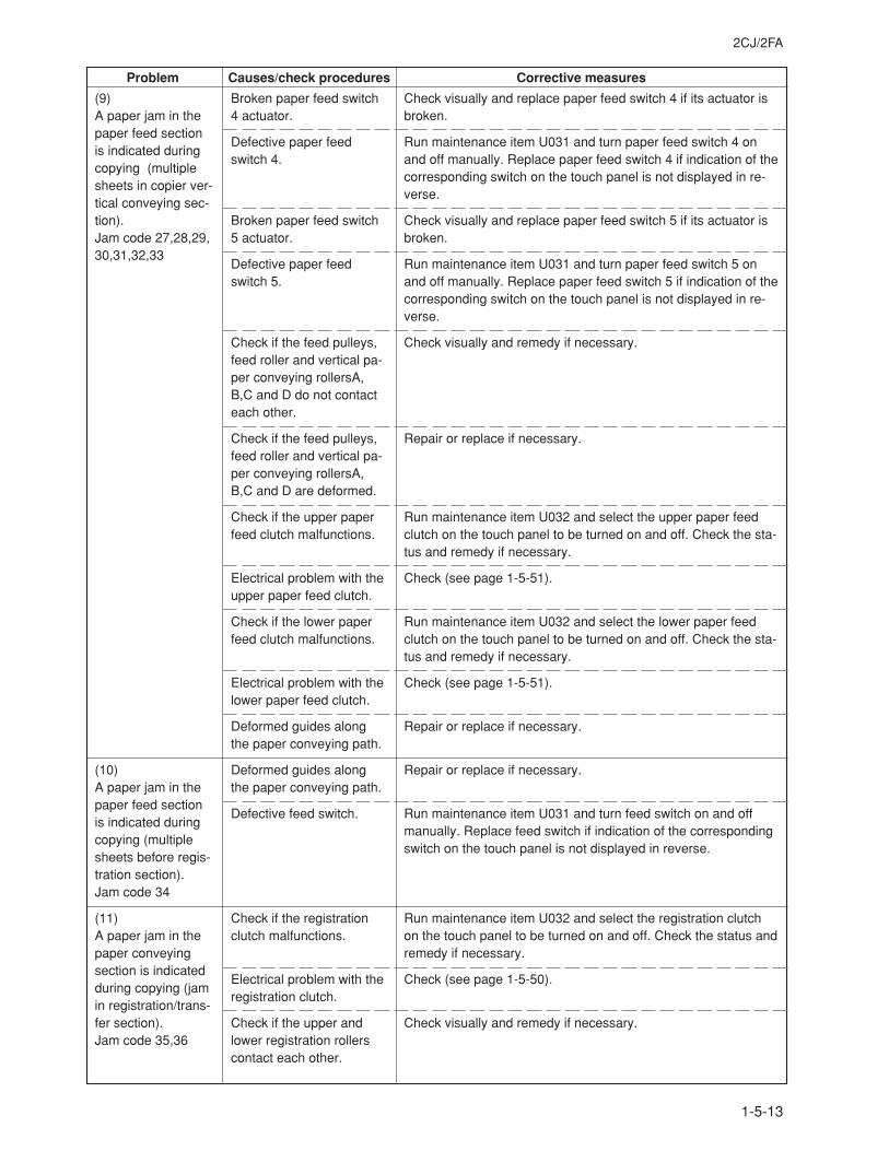
2CJ/2FA
1-5-13
Problem Causes/check procedures Corrective measures
(9)A paper jam in thepaper feed sectionis indicated duringcopying (multiplesheets in copier ver-tical conveying sec-tion).Jam code 27,28,29,30,31,32,33
(10)A paper jam in thepaper feed sectionis indicated duringcopying (multiplesheets before regis-tration section).Jam code 34
(11)A paper jam in thepaper conveyingsection is indicatedduring copying (jamin registration/trans-fer section).Jam code 35,36
Broken paper feed switch4 actuator.
Defective paper feedswitch 4.
Broken paper feed switch5 actuator.
Defective paper feedswitch 5.
Check if the feed pulleys,feed roller and vertical pa-per conveying rollersA,B,C and D do not contacteach other.
Check if the feed pulleys,feed roller and vertical pa-per conveying rollersA,B,C and D are deformed.
Check if the upper paperfeed clutch malfunctions.
Electrical problem with theupper paper feed clutch.
Check if the lower paperfeed clutch malfunctions.
Electrical problem with thelower paper feed clutch.
Deformed guides alongthe paper conveying path.
Deformed guides alongthe paper conveying path.
Defective feed switch.
Check if the registrationclutch malfunctions.
Electrical problem with theregistration clutch.
Check if the upper andlower registration rollerscontact each other.
Check visually and replace paper feed switch 4 if its actuator isbroken.
Run maintenance item U031 and turn paper feed switch 4 onand off manually. Replace paper feed switch 4 if indication of thecorresponding switch on the touch panel is not displayed in re-verse.
Check visually and replace paper feed switch 5 if its actuator isbroken.
Run maintenance item U031 and turn paper feed switch 5 onand off manually. Replace paper feed switch 5 if indication of thecorresponding switch on the touch panel is not displayed in re-verse.
Check visually and remedy if necessary.
Repair or replace if necessary.
Run maintenance item U032 and select the upper paper feedclutch on the touch panel to be turned on and off. Check the sta-tus and remedy if necessary.
Check (see page 1-5-51).
Run maintenance item U032 and select the lower paper feedclutch on the touch panel to be turned on and off. Check the sta-tus and remedy if necessary.
Check (see page 1-5-51).
Repair or replace if necessary.
Repair or replace if necessary.
Run maintenance item U031 and turn feed switch on and offmanually. Replace feed switch if indication of the correspondingswitch on the touch panel is not displayed in reverse.
Run maintenance item U032 and select the registration clutchon the touch panel to be turned on and off. Check the status andremedy if necessary.
Check (see page 1-5-50).
Check visually and remedy if necessary.
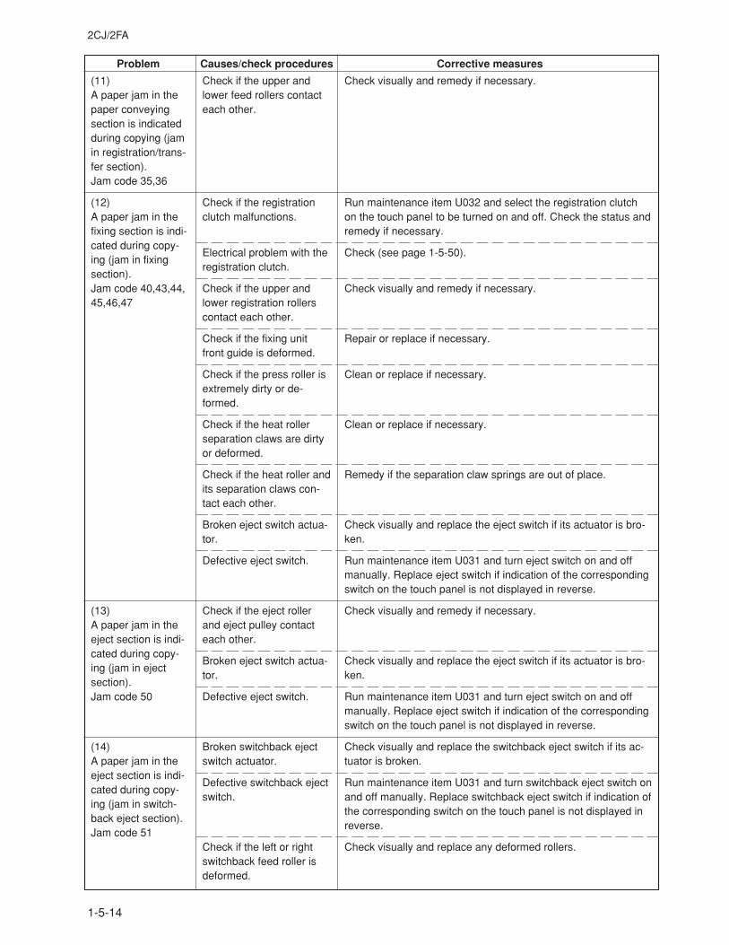
2CJ/2FA
1-5-14
Problem Causes/check procedures Corrective measures
(11)A paper jam in thepaper conveyingsection is indicatedduring copying (jamin registration/trans-fer section).Jam code 35,36
(12)A paper jam in thefixing section is indi-cated during copy-ing (jam in fixingsection).Jam code 40,43,44,45,46,47
(13)A paper jam in theeject section is indi-cated during copy-ing (jam in ejectsection).Jam code 50
(14)A paper jam in theeject section is indi-cated during copy-ing (jam in switch-back eject section).Jam code 51
Check if the upper andlower feed rollers contacteach other.
Check if the registrationclutch malfunctions.
Electrical problem with theregistration clutch.
Check if the upper andlower registration rollerscontact each other.
Check if the fixing unitfront guide is deformed.
Check if the press roller isextremely dirty or de-formed.
Check if the heat rollerseparation claws are dirtyor deformed.
Check if the heat roller andits separation claws con-tact each other.
Broken eject switch actua-tor.
Defective eject switch.
Check if the eject rollerand eject pulley contacteach other.
Broken eject switch actua-tor.
Defective eject switch.
Broken switchback ejectswitch actuator.
Defective switchback ejectswitch.
Check if the left or rightswitchback feed roller isdeformed.
Check visually and remedy if necessary.
Run maintenance item U032 and select the registration clutchon the touch panel to be turned on and off. Check the status andremedy if necessary.
Check (see page 1-5-50).
Check visually and remedy if necessary.
Repair or replace if necessary.
Clean or replace if necessary.
Clean or replace if necessary.
Remedy if the separation claw springs are out of place.
Check visually and replace the eject switch if its actuator is bro-ken.
Run maintenance item U031 and turn eject switch on and offmanually. Replace eject switch if indication of the correspondingswitch on the touch panel is not displayed in reverse.
Check visually and remedy if necessary.
Check visually and replace the eject switch if its actuator is bro-ken.
Run maintenance item U031 and turn eject switch on and offmanually. Replace eject switch if indication of the correspondingswitch on the touch panel is not displayed in reverse.
Check visually and replace the switchback eject switch if its ac-tuator is broken.
Run maintenance item U031 and turn switchback eject switch onand off manually. Replace switchback eject switch if indication ofthe corresponding switch on the touch panel is not displayed inreverse.
Check visually and replace any deformed rollers.
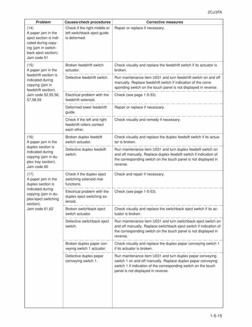
2CJ/2FA
1-5-15
Problem Causes/check procedures Corrective measures
(14)A paper jam in theeject section is indi-cated during copy-ing (jam in switch-back eject section).Jam code 51
(15)A paper jam in thefeedshift section isindicated duringcopying (jam infeedshift section).Jam code 52,55,56,57,58,59
(16)A paper jam in theduplex section isindicated duringcopying (jam in du-plex tray section).Jam code 60
(17)A paper jam in theduplex section isindicated duringcopying (jam in du-plex/eject switchingsection).Jam code 61,62
Check if the right middle orleft switchback eject guideis deformed.
Broken feedshift switchactuator.
Defective feedshift switch.
Electrical problem with thefeedshift solenoid.
Deformed lower feedshiftguide.
Check if the left and rightfeedshift rollers contacteach other.
Broken duplex feedsiftswitch actuator.
Defective duplex feedsiftswitch.
Check if the duplex ejectswitching solenoid mal-functions.
Electrical problem with theduplex eject switching so-lenoid.
Broken switchback ejectswitch actuator.
Defective switchback ejectswitch.
Broken duplex paper con-veying switch 1 actuator.
Defective duplex peparconveying switch 1.
Repair or replace if necessary.
Check visually and replace the feedshift switch if its actuator isbroken.
Run maintenance item U031 and turn feedshift switch on and offmanually. Replace feedshift switch if indication of the corre-sponding switch on the touch panel is not displayed in reverse.
Check (see page 1-5-53).
Repair or replace if necessary.
Check visually and remedy if necessary.
Check visually and replace the duplex feedsift switch if its actua-tor is broken.
Run maintenance item U031 and turn duplex feedsift switch onand off manually. Replace duplex feedsift switch if indication ofthe corresponding switch on the touch panel is not displayed inreverse.
Check and repair if necessary.
Check (see page 1-5-53).
Check visually and replace the switchback eject switch if its ac-tuator is broken.
Run maintenance item U031 and turn switchback eject switch onand off manually. Replace switchback eject switch if indication ofthe corresponding switch on the touch panel is not displayed inreverse.
Check visually and replace the duplex pepar conveying switch 1if its actuator is broken.
Run maintenance item U031 and turn duplex pepar conveyingswitch 1 on and off manually. Replace duplex pepar conveyingswitch 1 if indication of the corresponding switch on the touchpanel is not displayed in reverse.
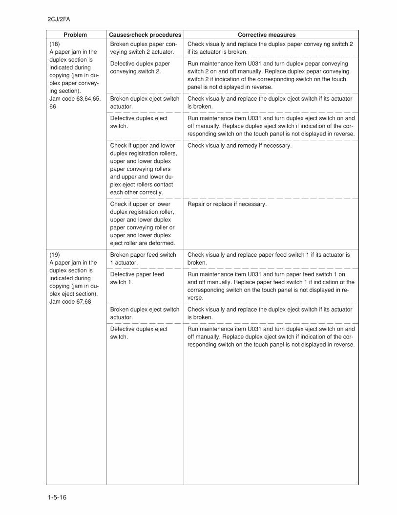
2CJ/2FA
1-5-16
Problem Causes/check procedures Corrective measures
(18)A paper jam in theduplex section isindicated duringcopying (jam in du-plex paper convey-ing section).Jam code 63,64,65,66
(19)A paper jam in theduplex section isindicated duringcopying (jam in du-plex eject section).Jam code 67,68
Broken duplex paper con-veying switch 2 actuator.
Defective duplex paperconveying switch 2.
Broken duplex eject switchactuator.
Defective duplex ejectswitch.
Check if upper and lowerduplex registration rollers,upper and lower duplexpaper conveying rollersand upper and lower du-plex eject rollers contacteach other correctly.
Check if upper or lowerduplex registration roller,upper and lower duplexpaper conveying roller orupper and lower duplexeject roller are deformed.
Broken paper feed switch1 actuator.
Defective paper feedswitch 1.
Broken duplex eject switchactuator.
Defective duplex ejectswitch.
Check visually and replace the duplex paper conveying switch 2if its actuator is broken.
Run maintenance item U031 and turn duplex pepar conveyingswitch 2 on and off manually. Replace duplex pepar conveyingswitch 2 if indication of the corresponding switch on the touchpanel is not displayed in reverse.
Check visually and replace the duplex eject switch if its actuatoris broken.
Run maintenance item U031 and turn duplex eject switch on andoff manually. Replace duplex eject switch if indication of the cor-responding switch on the touch panel is not displayed in reverse.
Check visually and remedy if necessary.
Repair or replace if necessary.
Check visually and replace paper feed switch 1 if its actuator isbroken.
Run maintenance item U031 and turn paper feed switch 1 onand off manually. Replace paper feed switch 1 if indication of thecorresponding switch on the touch panel is not displayed in re-verse.
Check visually and replace the duplex eject switch if its actuatoris broken.
Run maintenance item U031 and turn duplex eject switch on andoff manually. Replace duplex eject switch if indication of the cor-responding switch on the touch panel is not displayed in reverse.
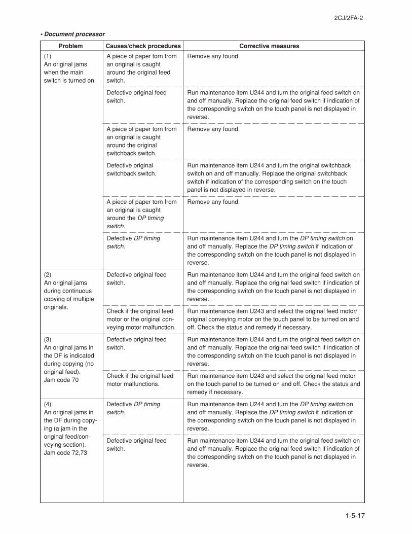
2CJ/2FA-2
1-5-17
Problem Causes/check procedures Corrective measures
• Document processor
(1)An original jamswhen the mainswitch is turned on.
(2)An original jamsduring continuouscopying of multipleoriginals.
(3)An original jams inthe DF is indicatedduring copying (nooriginal feed).Jam code 70
(4)An original jams inthe DF during copy-ing (a jam in theoriginal feed/con-veying section).Jam code 72,73
A piece of paper torn froman original is caughtaround the original feedswitch.
Defective original feedswitch.
A piece of paper torn froman original is caughtaround the originalswitchback switch.
Defective originalswitchback switch.
A piece of paper torn froman original is caughtaround the DP timingswitch.
Defective DP timingswitch.
Defective original feedswitch.
Check if the original feedmotor or the original con-veying motor malfunction.
Defective original feedswitch.
Check if the original feedmotor malfunctions.
Defective DP timingswitch.
Defective original feedswitch.
Remove any found.
Run maintenance item U244 and turn the original feed switch onand off manually. Replace the original feed switch if indication ofthe corresponding switch on the touch panel is not displayed inreverse.
Remove any found.
Run maintenance item U244 and turn the original switchbackswitch on and off manually. Replace the original switchbackswitch if indication of the corresponding switch on the touchpanel is not displayed in reverse.
Remove any found.
Run maintenance item U244 and turn the DP timing switch onand off manually. Replace the DP timing switch if indication ofthe corresponding switch on the touch panel is not displayed inreverse.
Run maintenance item U244 and turn the original feed switch onand off manually. Replace the original feed switch if indication ofthe corresponding switch on the touch panel is not displayed inreverse.
Run maintenance item U243 and select the original feed motor/original conveying motor on the touch panel to be turned on andoff. Check the status and remedy if necessary.
Run maintenance item U244 and turn the original feed switch onand off manually. Replace the original feed switch if indication ofthe corresponding switch on the touch panel is not displayed inreverse.
Run maintenance item U243 and select the original feed motoron the touch panel to be turned on and off. Check the status andremedy if necessary.
Run maintenance item U244 and turn the DP timing switch onand off manually. Replace the DP timing switch if indication ofthe corresponding switch on the touch panel is not displayed inreverse.
Run maintenance item U244 and turn the original feed switch onand off manually. Replace the original feed switch if indication ofthe corresponding switch on the touch panel is not displayed inreverse.
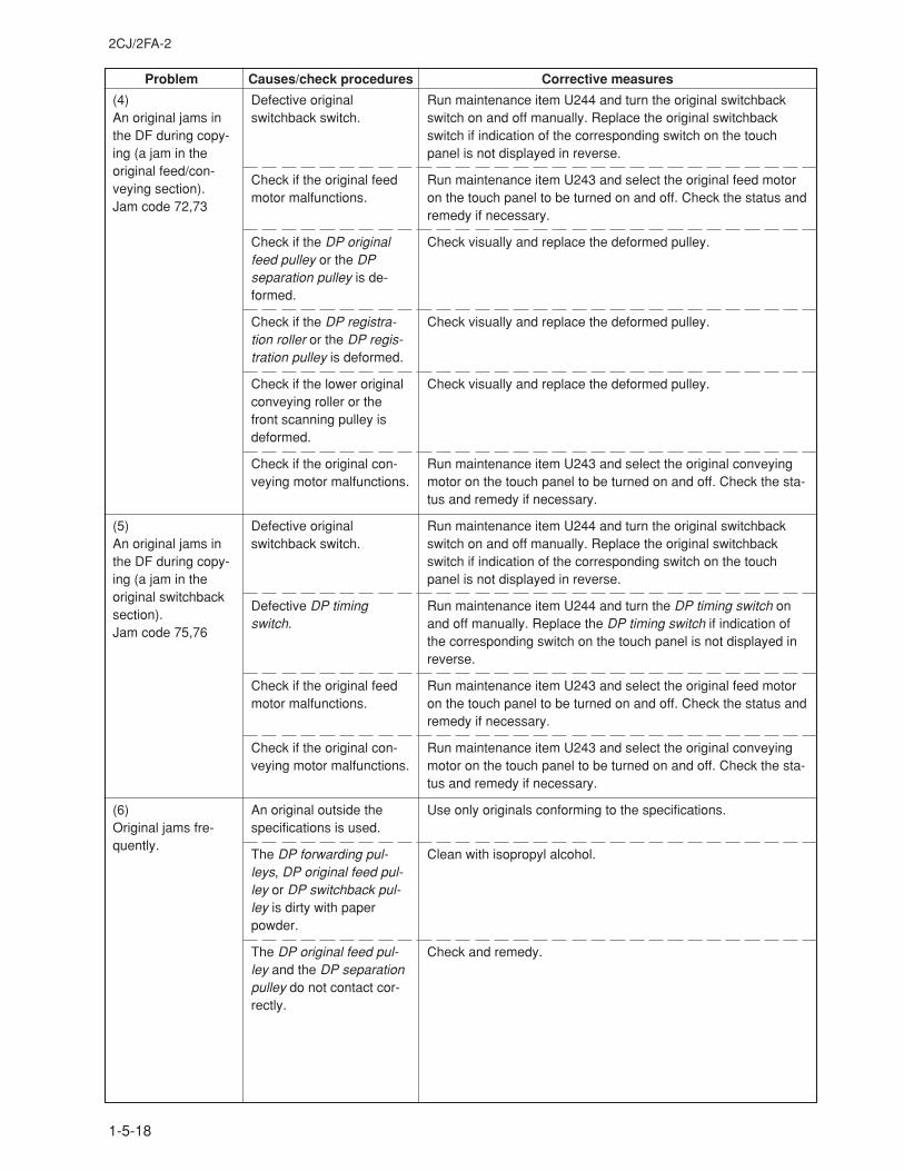
2CJ/2FA-2
1-5-18
Problem Causes/check procedures Corrective measures
(4)An original jams inthe DF during copy-ing (a jam in theoriginal feed/con-veying section).Jam code 72,73
(5)An original jams inthe DF during copy-ing (a jam in theoriginal switchbacksection).Jam code 75,76
(6)Original jams fre-quently.
Defective originalswitchback switch.
Check if the original feedmotor malfunctions.
Check if the DP originalfeed pulley or the DPseparation pulley is de-formed.
Check if the DP registra-tion roller or the DP regis-tration pulley is deformed.
Check if the lower originalconveying roller or thefront scanning pulley isdeformed.
Check if the original con-veying motor malfunctions.
Defective originalswitchback switch.
Defective DP timingswitch.
Check if the original feedmotor malfunctions.
Check if the original con-veying motor malfunctions.
An original outside thespecifications is used.
The DP forwarding pul-leys, DP original feed pul-ley or DP switchback pul-ley is dirty with paperpowder.
The DP original feed pul-ley and the DP separationpulley do not contact cor-rectly.
Run maintenance item U244 and turn the original switchbackswitch on and off manually. Replace the original switchbackswitch if indication of the corresponding switch on the touchpanel is not displayed in reverse.
Run maintenance item U243 and select the original feed motoron the touch panel to be turned on and off. Check the status andremedy if necessary.
Check visually and replace the deformed pulley.
Check visually and replace the deformed pulley.
Check visually and replace the deformed pulley.
Run maintenance item U243 and select the original conveyingmotor on the touch panel to be turned on and off. Check the sta-tus and remedy if necessary.
Run maintenance item U244 and turn the original switchbackswitch on and off manually. Replace the original switchbackswitch if indication of the corresponding switch on the touchpanel is not displayed in reverse.
Run maintenance item U244 and turn the DP timing switch onand off manually. Replace the DP timing switch if indication ofthe corresponding switch on the touch panel is not displayed inreverse.
Run maintenance item U243 and select the original feed motoron the touch panel to be turned on and off. Check the status andremedy if necessary.
Run maintenance item U243 and select the original conveyingmotor on the touch panel to be turned on and off. Check the sta-tus and remedy if necessary.
Use only originals conforming to the specifications.
Clean with isopropyl alcohol.
Check and remedy.
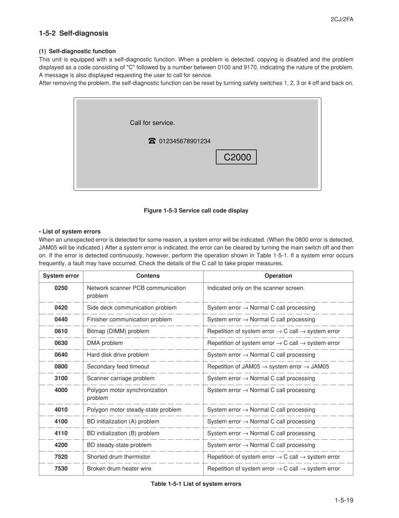
2CJ/2FA
1-5-19
1-5-2 Self-diagnosis
(1) Self-diagnostic functionThis unit is equipped with a self-diagnostic function. When a problem is detected, copying is disabled and the problemdisplayed as a code consisting of "C" followed by a number between 0100 and 9170, indicating the nature of the problem.A message is also displayed requesting the user to call for service.After removing the problem, the self-diagnostic function can be reset by turning safety switches 1, 2, 3 or 4 off and back on.
Figure 1-5-3 Service call code display
012345678901234
C2000
Call for service.
• List of system errorsWhen an unexpected error is detected for some reason, a system error will be indicated. (When the 0800 error is detected,JAM05 will be indicated.) After a system error is indicated, the error can be cleared by turning the main switch off and thenon. If the error is detected continuously, however, perform the operation shown in Table 1-5-1. If a system error occursfrequently, a fault may have occurred. Check the details of the C call to take proper measures.
System error Contens Operation
0250
0420
0440
0610
0630
0640
0800
3100
4000
4010
4100
4110
4200
7520
7530
Network scanner PCB communicationproblem
Side deck communication problem
Finisher communication problem
Bitmap (DIMM) problem
DMA problem
Hard disk drive problem
Secondary feed timeout
Scanner carriage problem
Polygon motor synchronizationproblem
Polygon motor steady-state problem
BD initialization (A) problem
BD initialization (B) problem
BD steady-state problem
Shorted drum thermistor
Broken drum heater wire
Indicated only on the scanner screen.
System error → Normal C call processing
System error → Normal C call processing
Repetition of system error → C call → system error
Repetition of system error → C call → system error
System error → Normal C call processing
Repetition of JAM05 → system error → JAM05
System error → Normal C call processing
System error → Normal C call processing
System error → Normal C call processing
System error → Normal C call processing
System error → Normal C call processing
System error → Normal C call processing
Repetition of system error → C call → system error
Repetition of system error → C call → system error
Table 1-5-1 List of system errors
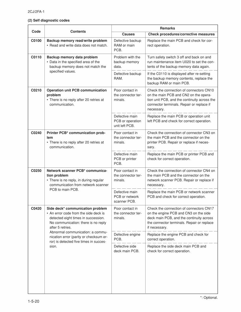
2CJ/2FA-1
1-5-20
(2) Self diagnostic codes
Code ContentsRemarks
Causes Check procedures/corrective measures
C0100
C0110
C0210
C0240
C0250
C0420
Backup memory read/write problem• Read and write data does not match.
Backup memory data problem• Data in the specified area of the
backup memory does not match thespecified values.
Operation unit PCB communicationproblem• There is no reply after 20 retries at
communication.
Printer PCB* communication prob-lem• There is no reply after 20 retries at
communication.
Network scanner PCB* communica-tion problem• There is no reply, in during regular
communication from network scannerPCB to main PCB.
Side deck* communication problem• An error code from the side deck is
detected eight times in succession.No communication: there is no replyafter 5 retries.Abnormal communication: a commu-nication error (parity or checksum er-ror) is detected five times in succes-sion.
Defective backupRAM or mainPCB.
Problem with thebackup memorydata.
Defective backupRAM.
Poor contact inthe connector ter-minals.
Defective mainPCB or operationunit left PCB.
Poor contact inthe connector ter-minals.
Defective mainPCB or printerPCB.
Poor contact inthe connector ter-minals.
Defective mainPCB or networkscanner PCB.
Poor contact inthe connector ter-minals.
Defective enginePCB.
Defective sidedeck main PCB.
Replace the main PCB and check for cor-rect operation.
Turn safety switch 3 off and back on andrun maintenance item U020 to set the con-tents of the backup memory data again.
If the C0110 is displayed after re-settingthe backup memory contents, replace thebackup RAM or main PCB.
Check the connection of connectors CN10on the main PCB and CN2 on the opera-tion unit PCB, and the continuity across theconnector terminals. Repair or replace ifnecessary.
Replace the main PCB or operation unitleft PCB and check for correct operation.
Check the connection of connector CN3 onthe main PCB and the connector on theprinter PCB. Repair or replace if neces-sary.
Replace the main PCB or printer PCB andcheck for correct operation.
Check the connection of connector CN4 onthe main PCB and the connector on thenetwork scanner PCB. Repair or replace ifnecessary.
Replace the main PCB or network scannerPCB and check for correct operation.
Check the connection of connectors CN17on the engine PCB and CN3 on the sidedeck main PCB, and the continuity acrossthe connector terminals. Repair or replaceif necessary.
Replace the engine PCB and check forcorrect operation.
Replace the side deck main PCB andcheck for correct operation.
*: Optional.
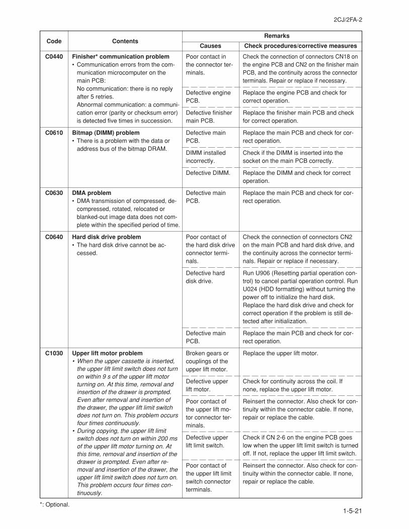
2CJ/2FA-2
1-5-21
Code ContentsRemarks
Causes Check procedures/corrective measures
C0440
C0610
C0630
C0640
C1030
Finisher* communication problem• Communication errors from the com-
munication microcomputer on themain PCB:No communication: there is no replyafter 5 retries.Abnormal communication: a communi-cation error (parity or checksum error)is detected five times in succession.
Bitmap (DIMM) problem• There is a problem with the data or
address bus of the bitmap DRAM.
DMA problem• DMA transmission of compressed, de-
compressed, rotated, relocated orblanked-out image data does not com-plete within the specified period of time.
Hard disk drive problem• The hard disk drive cannot be ac-
cessed.
Upper lift motor problem• When the upper cassette is inserted,
the upper lift limit switch does not turnon within 9 s of the upper lift motorturning on. At this time, removal andinsertion of the drawer is prompted.Even after removal and insertion ofthe drawer, the upper lift limit switchdoes not turn on. This problem occursfour times continuously.
• During copying, the upper lift limitswitch does not turn on within 200 msof the upper lift motor turning on. Atthis time, removal and insertion of thedrawer is prompted. Even after re-moval and insertion of the drawer, theupper lift limit switch does not turn on.This problem occurs four times con-tinuously.
Poor contact inthe connector ter-minals.
Defective enginePCB.
Defective finishermain PCB.
Defective mainPCB.
DIMM installedincorrectly.
Defective DIMM.
Defective mainPCB.
Poor contact ofthe hard disk driveconnector termi-nals.
Defective harddisk drive.
Defective mainPCB.
Broken gears orcouplings of theupper lift motor.
Defective upperlift motor.
Poor contact ofthe upper lift mo-tor connector ter-minals.
Defective upperlift limit switch.
Poor contact ofthe upper lift limitswitch connectorterminals.
Check the connection of connectors CN18 onthe engine PCB and CN2 on the finisher mainPCB, and the continuity across the connectorterminals. Repair or replace if necessary.
Replace the engine PCB and check forcorrect operation.
Replace the finisher main PCB and checkfor correct operation.
Replace the main PCB and check for cor-rect operation.
Check if the DIMM is inserted into thesocket on the main PCB correctly.
Replace the DIMM and check for correctoperation.
Replace the main PCB and check for cor-rect operation.
Check the connection of connectors CN2on the main PCB and hard disk drive, andthe continuity across the connector termi-nals. Repair or replace if necessary.
Run U906 (Resetting partial operation con-trol) to cancel partial operation control. RunU024 (HDD formatting) without turning thepower off to initialize the hard disk.Replace the hard disk drive and check forcorrect operation if the problem is still de-tected after initialization.
Replace the main PCB and check for cor-rect operation.
Replace the upper lift motor.
Check for continuity across the coil. Ifnone, replace the upper lift motor.
Reinsert the connector. Also check for con-tinuity within the connector cable. If none,repair or replace the cable.
Check if CN 2-6 on the engine PCB goeslow when the upper lift limit switch is turnedoff. If not, replace the upper lift limit switch.
Reinsert the connector. Also check for con-tinuity within the connector cable. If none,repair or replace the cable.
*: Optional.
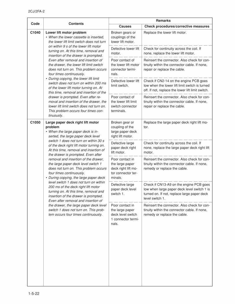
2CJ/2FA-2
1-5-22
Code ContentsRemarks
Causes Check procedures/corrective measures
C1040
C1050
Lower lift motor problem• When the lower cassette is inserted,
the lower lift limit switch does not turnon within 9 s of the lower lift motorturning on. At this time, removal andinsertion of the drawer is prompted.Even after removal and insertion ofthe drawer, the lower lift limit switchdoes not turn on. This problem occursfour times continuously.
• During copying, the lower lift limitswitch does not turn on within 200 msof the lower lift motor turning on. Atthis time, removal and insertion of thedrawer is prompted. Even after re-moval and insertion of the drawer, thelower lift limit switch does not turn on.This problem occurs four times con-tinuously.
Large paper deck right lift motorproblem• When the large paper deck is in-
serted, the large paper deck levelswitch 1 does not turn on within 30 sof the deck right lift motor turning on.At this time, removal and insertion ofthe drawer is prompted. Even afterremoval and insertion of the drawer,the large paper deck level switch 1does not turn on. This problem occursfour times continuously.
• During copying, the large paper decklevel switch 1 does not turn on within200 ms of the deck right lift motorturning on. At this time, removal andinsertion of the drawer is prompted.Even after removal and insertion ofthe drawer, the large paper deck levelswitch 1 does not turn on. This prob-lem occurs four times continuously.
Broken gears orcouplings of thelower lift motor.
Defective lower liftmotor.
Poor contact ofthe lower lift motorconnector termi-nals.
Defective lower liftlimit switch.
Poor contact ofthe lower lift limitswitch connectorterminals.
Broken gear orcoupling of thelarge paper deckright lift motor.
Defective largepaper deck rightlift motor.
Poor contact inthe large paperdeck right lift mo-tor connector ter-minals.
Defective largepaper deck levelswitch 1.
Poor contact inthe large paperdeck level switch1 connector termi-nals.
Replace the lower lift motor.
Check for continuity across the coil. Ifnone, replace the lower lift motor.
Reinsert the connector. Also check for con-tinuity within the connector cable. If none,repair or replace the cable.
Check if CN2-14 on the engine PCB goeslow when the lower lift limit switch is turnedoff. If not, replace the lower lift limit switch.
Reinsert the connector. Also check for con-tinuity within the connector cable. If none,repair or replace the cable.
Replace the large paper deck right lift mo-tor.
Check for continuity across the coil. Ifnone, replace the large paper deck right liftmotor.
Reinsert the connector. Also check for con-tinuity within the connector cable. If none,remedy or replace the cable.
Check if CN13-A9 on the engine PCB goeslow when large paper deck level switch 1 isturned on. If not, replace large paper decklevel switch 1.
Reinsert the connector. Also check for con-tinuity within the connector cable. If none,remedy or replace the cable.
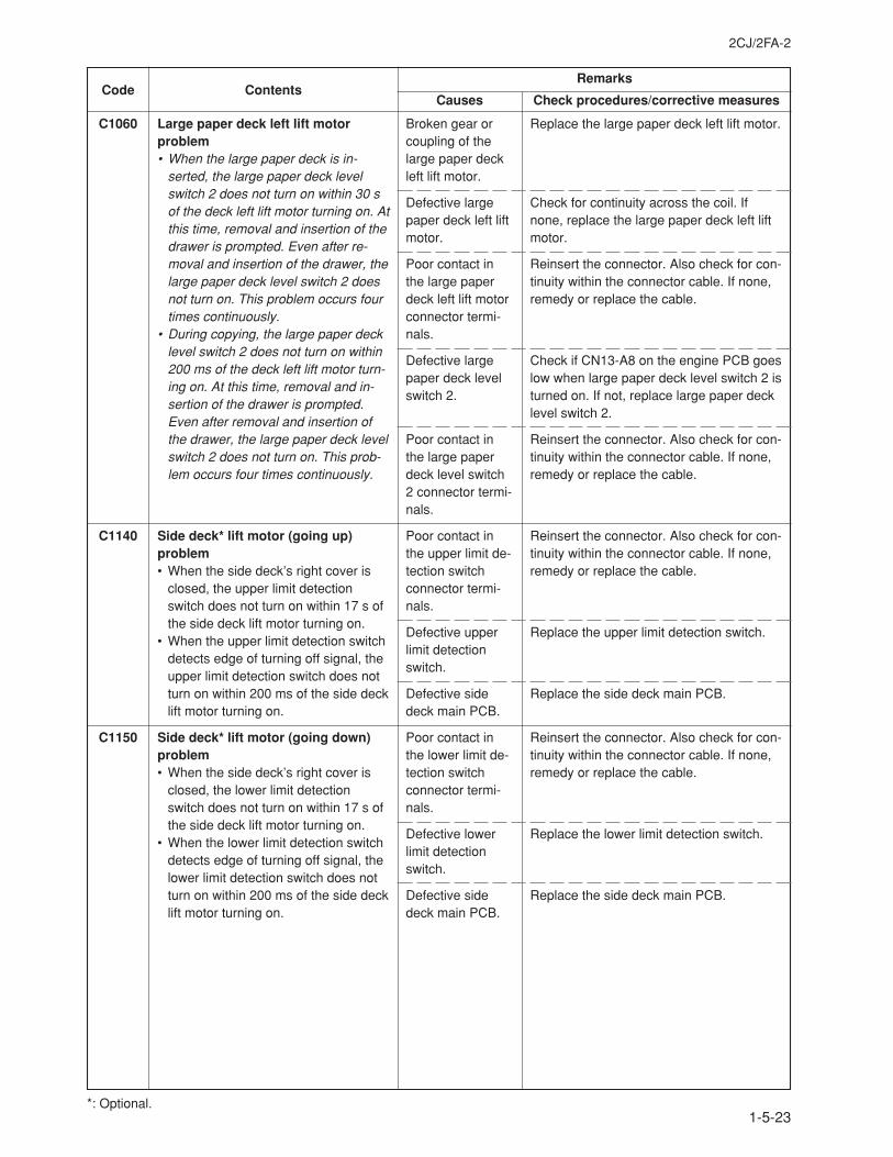
2CJ/2FA-2
1-5-23
Code ContentsRemarks
Causes Check procedures/corrective measures
C1060
C1140
C1150
Large paper deck left lift motorproblem• When the large paper deck is in-
serted, the large paper deck levelswitch 2 does not turn on within 30 sof the deck left lift motor turning on. Atthis time, removal and insertion of thedrawer is prompted. Even after re-moval and insertion of the drawer, thelarge paper deck level switch 2 doesnot turn on. This problem occurs fourtimes continuously.
• During copying, the large paper decklevel switch 2 does not turn on within200 ms of the deck left lift motor turn-ing on. At this time, removal and in-sertion of the drawer is prompted.Even after removal and insertion ofthe drawer, the large paper deck levelswitch 2 does not turn on. This prob-lem occurs four times continuously.
Side deck* lift motor (going up)problem• When the side deck’s right cover is
closed, the upper limit detectionswitch does not turn on within 17 s ofthe side deck lift motor turning on.
• When the upper limit detection switchdetects edge of turning off signal, theupper limit detection switch does notturn on within 200 ms of the side decklift motor turning on.
Side deck* lift motor (going down)problem• When the side deck’s right cover is
closed, the lower limit detectionswitch does not turn on within 17 s ofthe side deck lift motor turning on.
• When the lower limit detection switchdetects edge of turning off signal, thelower limit detection switch does notturn on within 200 ms of the side decklift motor turning on.
Broken gear orcoupling of thelarge paper deckleft lift motor.
Defective largepaper deck left liftmotor.
Poor contact inthe large paperdeck left lift motorconnector termi-nals.
Defective largepaper deck levelswitch 2.
Poor contact inthe large paperdeck level switch2 connector termi-nals.
Poor contact inthe upper limit de-tection switchconnector termi-nals.
Defective upperlimit detectionswitch.
Defective sidedeck main PCB.
Poor contact inthe lower limit de-tection switchconnector termi-nals.
Defective lowerlimit detectionswitch.
Defective sidedeck main PCB.
Replace the large paper deck left lift motor.
Check for continuity across the coil. Ifnone, replace the large paper deck left liftmotor.
Reinsert the connector. Also check for con-tinuity within the connector cable. If none,remedy or replace the cable.
Check if CN13-A8 on the engine PCB goeslow when large paper deck level switch 2 isturned on. If not, replace large paper decklevel switch 2.
Reinsert the connector. Also check for con-tinuity within the connector cable. If none,remedy or replace the cable.
Reinsert the connector. Also check for con-tinuity within the connector cable. If none,remedy or replace the cable.
Replace the upper limit detection switch.
Replace the side deck main PCB.
Reinsert the connector. Also check for con-tinuity within the connector cable. If none,remedy or replace the cable.
Replace the lower limit detection switch.
Replace the side deck main PCB.
*: Optional.
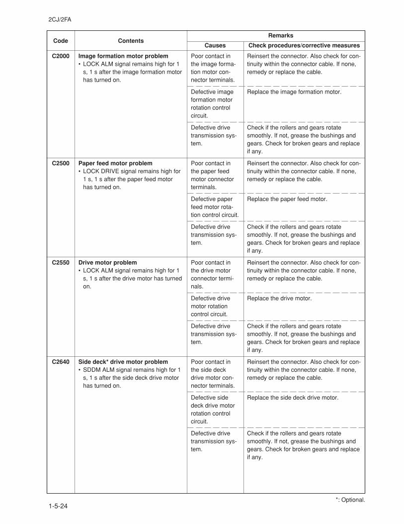
2CJ/2FA
1-5-24
Code ContentsRemarks
Causes Check procedures/corrective measures
C2000
C2500
C2550
C2640
Image formation motor problem• LOCK ALM signal remains high for 1
s, 1 s after the image formation motorhas turned on.
Paper feed motor problem• LOCK DRIVE signal remains high for
1 s, 1 s after the paper feed motorhas turned on.
Drive motor problem• LOCK ALM signal remains high for 1
s, 1 s after the drive motor has turnedon.
Side deck* drive motor problem• SDDM ALM signal remains high for 1
s, 1 s after the side deck drive motorhas turned on.
Poor contact inthe image forma-tion motor con-nector terminals.
Defective imageformation motorrotation controlcircuit.
Defective drivetransmission sys-tem.
Poor contact inthe paper feedmotor connectorterminals.
Defective paperfeed motor rota-tion control circuit.
Defective drivetransmission sys-tem.
Poor contact inthe drive motorconnector termi-nals.
Defective drivemotor rotationcontrol circuit.
Defective drivetransmission sys-tem.
Poor contact inthe side deckdrive motor con-nector terminals.
Defective sidedeck drive motorrotation controlcircuit.
Defective drivetransmission sys-tem.
Reinsert the connector. Also check for con-tinuity within the connector cable. If none,remedy or replace the cable.
Replace the image formation motor.
Check if the rollers and gears rotatesmoothly. If not, grease the bushings andgears. Check for broken gears and replaceif any.
Reinsert the connector. Also check for con-tinuity within the connector cable. If none,remedy or replace the cable.
Replace the paper feed motor.
Check if the rollers and gears rotatesmoothly. If not, grease the bushings andgears. Check for broken gears and replaceif any.
Reinsert the connector. Also check for con-tinuity within the connector cable. If none,remedy or replace the cable.
Replace the drive motor.
Check if the rollers and gears rotatesmoothly. If not, grease the bushings andgears. Check for broken gears and replaceif any.
Reinsert the connector. Also check for con-tinuity within the connector cable. If none,remedy or replace the cable.
Replace the side deck drive motor.
Check if the rollers and gears rotatesmoothly. If not, grease the bushings andgears. Check for broken gears and replaceif any.
*: Optional.
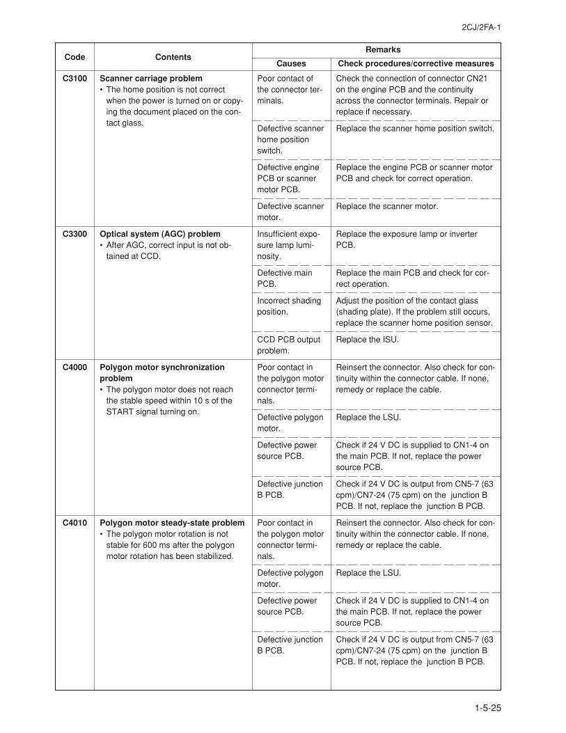
2CJ/2FA-1
1-5-25
Code ContentsRemarks
Causes Check procedures/corrective measures
C3100
C3300
C4000
C4010
Scanner carriage problem• The home position is not correct
when the power is turned on or copy-ing the document placed on the con-tact glass.
Optical system (AGC) problem• After AGC, correct input is not ob-
tained at CCD.
Polygon motor synchronizationproblem• The polygon motor does not reach
the stable speed within 10 s of theSTART signal turning on.
Polygon motor steady-state problem• The polygon motor rotation is not
stable for 600 ms after the polygonmotor rotation has been stabilized.
Poor contact ofthe connector ter-minals.
Defective scannerhome positionswitch.
Defective enginePCB or scannermotor PCB.
Defective scannermotor.
Insufficient expo-sure lamp lumi-nosity.
Defective mainPCB.
Incorrect shadingposition.
CCD PCB outputproblem.
Poor contact inthe polygon motorconnector termi-nals.
Defective polygonmotor.
Defective powersource PCB.
Defective junctionB PCB.
Poor contact inthe polygon motorconnector termi-nals.
Defective polygonmotor.
Defective powersource PCB.
Defective junctionB PCB.
Check the connection of connector CN21on the engine PCB and the continuityacross the connector terminals. Repair orreplace if necessary.
Replace the scanner home position switch.
Replace the engine PCB or scanner motorPCB and check for correct operation.
Replace the scanner motor.
Replace the exposure lamp or inverterPCB.
Replace the main PCB and check for cor-rect operation.
Adjust the position of the contact glass(shading plate). If the problem still occurs,replace the scanner home position sensor.
Replace the ISU.
Reinsert the connector. Also check for con-tinuity within the connector cable. If none,remedy or replace the cable.
Replace the LSU.
Check if 24 V DC is supplied to CN1-4 onthe main PCB. If not, replace the powersource PCB.
Check if 24 V DC is output from CN5-7 (63cpm)/CN7-24 (75 cpm) on the junction BPCB. If not, replace the junction B PCB.
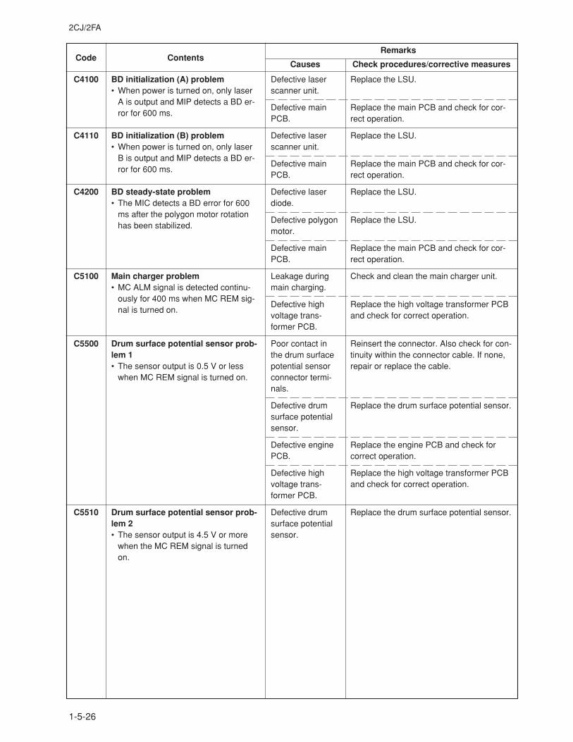
2CJ/2FA
1-5-26
Code ContentsRemarks
Causes Check procedures/corrective measures
C4100
C4110
C4200
C5100
C5500
C5510
BD initialization (A) problem• When power is turned on, only laser
A is output and MIP detects a BD er-ror for 600 ms.
BD initialization (B) problem• When power is turned on, only laser
B is output and MIP detects a BD er-ror for 600 ms.
BD steady-state problem• The MIC detects a BD error for 600
ms after the polygon motor rotationhas been stabilized.
Main charger problem• MC ALM signal is detected continu-
ously for 400 ms when MC REM sig-nal is turned on.
Drum surface potential sensor prob-lem 1• The sensor output is 0.5 V or less
when MC REM signal is turned on.
Drum surface potential sensor prob-lem 2• The sensor output is 4.5 V or more
when the MC REM signal is turnedon.
Defective laserscanner unit.
Defective mainPCB.
Defective laserscanner unit.
Defective mainPCB.
Defective laserdiode.
Defective polygonmotor.
Defective mainPCB.
Leakage duringmain charging.
Defective highvoltage trans-former PCB.
Poor contact inthe drum surfacepotential sensorconnector termi-nals.
Defective drumsurface potentialsensor.
Defective enginePCB.
Defective highvoltage trans-former PCB.
Defective drumsurface potentialsensor.
Replace the LSU.
Replace the main PCB and check for cor-rect operation.
Replace the LSU.
Replace the main PCB and check for cor-rect operation.
Replace the LSU.
Replace the LSU.
Replace the main PCB and check for cor-rect operation.
Check and clean the main charger unit.
Replace the high voltage transformer PCBand check for correct operation.
Reinsert the connector. Also check for con-tinuity within the connector cable. If none,repair or replace the cable.
Replace the drum surface potential sensor.
Replace the engine PCB and check forcorrect operation.
Replace the high voltage transformer PCBand check for correct operation.
Replace the drum surface potential sensor.
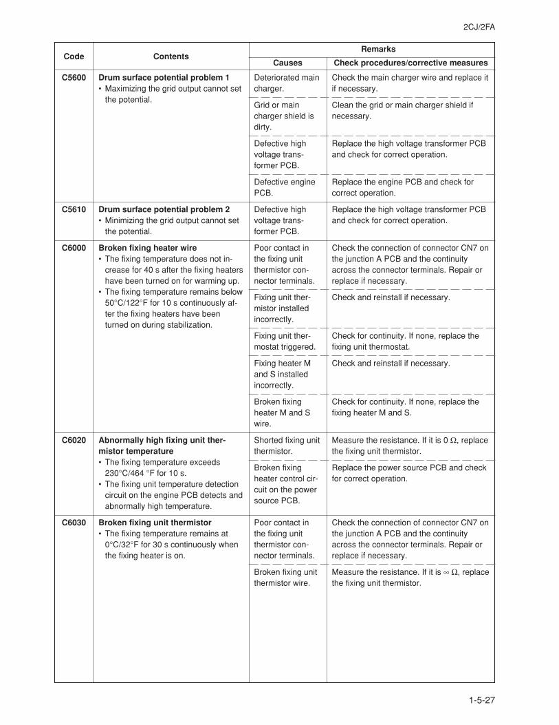
2CJ/2FA
1-5-27
Code ContentsRemarks
Causes Check procedures/corrective measures
C5600
C5610
C6000
C6020
C6030
Drum surface potential problem 1• Maximizing the grid output cannot set
the potential.
Drum surface potential problem 2• Minimizing the grid output cannot set
the potential.
Broken fixing heater wire• The fixing temperature does not in-
crease for 40 s after the fixing heatershave been turned on for warming up.
• The fixing temperature remains below50°C/122°F for 10 s continuously af-ter the fixing heaters have beenturned on during stabilization.
Abnormally high fixing unit ther-mistor temperature• The fixing temperature exceeds
230°C/464 °F for 10 s.• The fixing unit temperature detection
circuit on the engine PCB detects andabnormally high temperature.
Broken fixing unit thermistor• The fixing temperature remains at
0°C/32°F for 30 s continuously whenthe fixing heater is on.
Deteriorated maincharger.
Grid or maincharger shield isdirty.
Defective highvoltage trans-former PCB.
Defective enginePCB.
Defective highvoltage trans-former PCB.
Poor contact inthe fixing unitthermistor con-nector terminals.
Fixing unit ther-mistor installedincorrectly.
Fixing unit ther-mostat triggered.
Fixing heater Mand S installedincorrectly.
Broken fixingheater M and Swire.
Shorted fixing unitthermistor.
Broken fixingheater control cir-cuit on the powersource PCB.
Poor contact inthe fixing unitthermistor con-nector terminals.
Broken fixing unitthermistor wire.
Check the main charger wire and replace itif necessary.
Clean the grid or main charger shield ifnecessary.
Replace the high voltage transformer PCBand check for correct operation.
Replace the engine PCB and check forcorrect operation.
Replace the high voltage transformer PCBand check for correct operation.
Check the connection of connector CN7 onthe junction A PCB and the continuityacross the connector terminals. Repair orreplace if necessary.
Check and reinstall if necessary.
Check for continuity. If none, replace thefixing unit thermostat.
Check and reinstall if necessary.
Check for continuity. If none, replace thefixing heater M and S.
Measure the resistance. If it is 0 Ω, replacethe fixing unit thermistor.
Replace the power source PCB and checkfor correct operation.
Check the connection of connector CN7 onthe junction A PCB and the continuityacross the connector terminals. Repair orreplace if necessary.
Measure the resistance. If it is ∞ Ω, replacethe fixing unit thermistor.
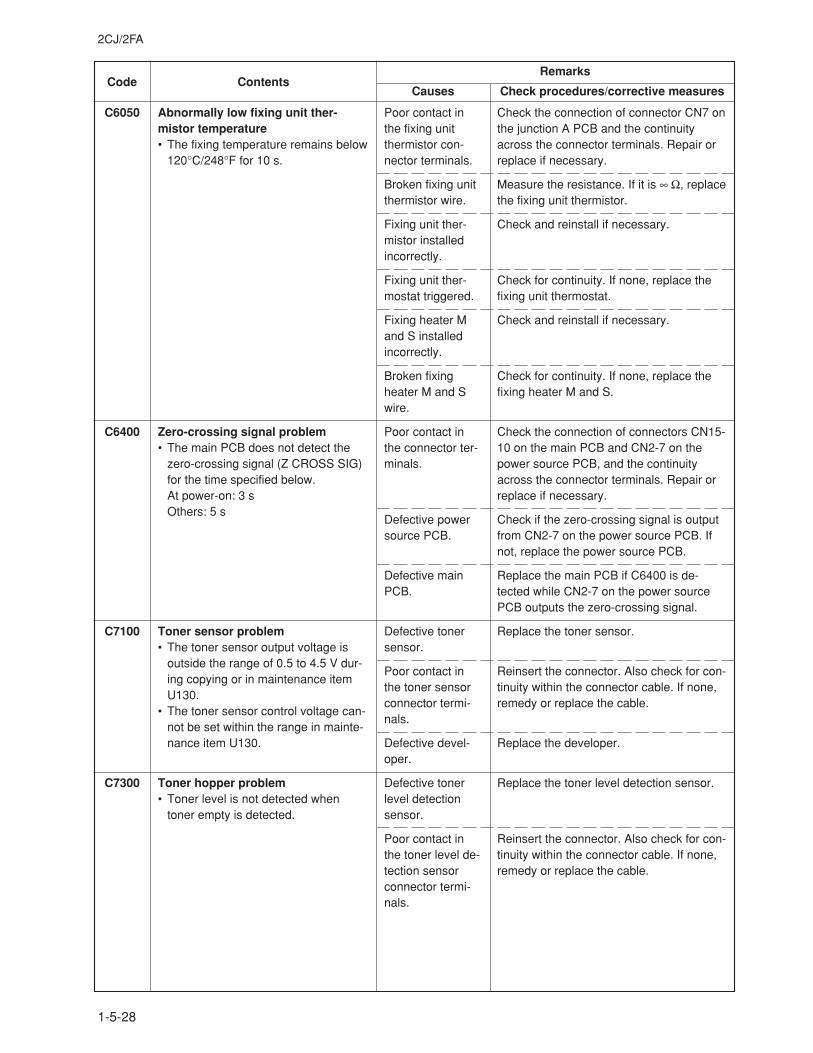
2CJ/2FA
1-5-28
Code ContentsRemarks
Causes Check procedures/corrective measures
C6050
C6400
C7100
C7300
Abnormally low fixing unit ther-mistor temperature• The fixing temperature remains below
120°C/248°F for 10 s.
Zero-crossing signal problem• The main PCB does not detect the
zero-crossing signal (Z CROSS SIG)for the time specified below.At power-on: 3 sOthers: 5 s
Toner sensor problem• The toner sensor output voltage is
outside the range of 0.5 to 4.5 V dur-ing copying or in maintenance itemU130.
• The toner sensor control voltage can-not be set within the range in mainte-nance item U130.
Toner hopper problem• Toner level is not detected when
toner empty is detected.
Poor contact inthe fixing unitthermistor con-nector terminals.
Broken fixing unitthermistor wire.
Fixing unit ther-mistor installedincorrectly.
Fixing unit ther-mostat triggered.
Fixing heater Mand S installedincorrectly.
Broken fixingheater M and Swire.
Poor contact inthe connector ter-minals.
Defective powersource PCB.
Defective mainPCB.
Defective tonersensor.
Poor contact inthe toner sensorconnector termi-nals.
Defective devel-oper.
Defective tonerlevel detectionsensor.
Poor contact inthe toner level de-tection sensorconnector termi-nals.
Check the connection of connector CN7 onthe junction A PCB and the continuityacross the connector terminals. Repair orreplace if necessary.
Measure the resistance. If it is ∞ Ω, replacethe fixing unit thermistor.
Check and reinstall if necessary.
Check for continuity. If none, replace thefixing unit thermostat.
Check and reinstall if necessary.
Check for continuity. If none, replace thefixing heater M and S.
Check the connection of connectors CN15-10 on the main PCB and CN2-7 on thepower source PCB, and the continuityacross the connector terminals. Repair orreplace if necessary.
Check if the zero-crossing signal is outputfrom CN2-7 on the power source PCB. Ifnot, replace the power source PCB.
Replace the main PCB if C6400 is de-tected while CN2-7 on the power sourcePCB outputs the zero-crossing signal.
Replace the toner sensor.
Reinsert the connector. Also check for con-tinuity within the connector cable. If none,remedy or replace the cable.
Replace the developer.
Replace the toner level detection sensor.
Reinsert the connector. Also check for con-tinuity within the connector cable. If none,remedy or replace the cable.
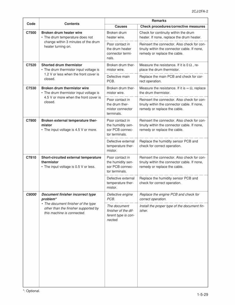
2CJ/2FA-2
1-5-29
Code ContentsRemarks
Causes Check procedures/corrective measures
C7500
C7520
C7530
C7800
C7810
C8000
Broken drum heater wire• The drum temperature does not
change within 3 minutes of the drumheater turning on.
Shorted drum thermistor• The drum thermistor input voltage is
1.2 V or less when the front cover isclosed.
Broken drum thermistor wire• The drum thermistor input voltage is
4.5 V or more when the front cover isclosed.
Broken external temperature ther-mistor• The input voltage is 4.5 V or more.
Short-circuited external temperaturethermistor• The input voltage is 0.5 V or less.
Document finisher incorrect typeproblem*• The document finisher of the type
other than the finisher supported bythis machine is connected.
Broken drumheater wire.
Poor contact inthe drum heaterconnector termi-nals.
Broken drum ther-mistor wire.
Defective mainPCB.
Broken drum ther-mistor wire.
Poor contact inthe drum ther-mistor connectorterminals.
Poor contact inthe humidity sen-sor PCB connec-tor terminals.
Defective externaltemperature ther-mistor.
Poor contact inthe humidity sen-sor PCB connec-tor terminals.
Defective externaltemperature ther-mistor.
Defective enginePCB.
The documentfinisher of the dif-ferent type is con-nected.
Check for continuity within the drumheater. If none, replace the drum heater.
Reinsert the connector. Also check for con-tinuity within the connector cable. If none,remedy or replace the cable.
Measure the resistance. If it is 0 Ω , re-place the drum thermistor.
Replace the main PCB and check for cor-rect operation.
Measure the resistance. If it is ∞ Ω, replacethe drum thermistor.
Reinsert the connector. Also check for con-tinuity within the connector cable. If none,remedy or replace the cable.
Reinsert the connector. Also check for con-tinuity within the connector cable. If none,remedy or replace the cable.
Replace the humidity sensor PCB andcheck for correct operation.
Reinsert the connector. Also check for con-tinuity within the connector cable. If none,remedy or replace the cable.
Replace the humidity sensor PCB andcheck for correct operation.
Replace the engine PCB and check forcorrect operation.
Install the proper type of the document fin-isher.
1-5-29*: Optional.
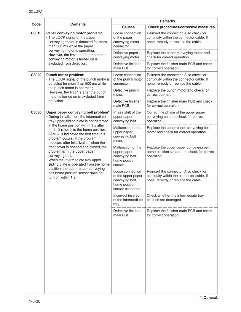
2CJ/2FA
1-5-30
Code ContentsRemarks
Causes Check procedures/corrective measures
C8010 Paper conveying motor problem*• The LOCK signal of the paper
conveying motor is detected for morethan 500 ms while the paperconveying motor is operating.However, the first 1 s after the paperconveying motor is turned on isexcluded from detection.
C8020 Punch motor problem*• The LOCK signal of the punch motor is
detected for more than 500 ms whilethe punch motor is operating.However, the first 1 s after the punchmotor is turned on is excluded fromdetection.
C8030 Upper paper conveying belt problem*• During initialization, the intermediate
tray upper sliding plate is not detectedin the home position within 3 s afterthe belt returns to the home position.JAM87 is indicated the first time thisproblem occurs. If the problemreoccurs after initialization when thefront cover is opened and closed, theproblem is in the upper paperconveying belt.
• When the intermediate tray uppersliding plate is operated from the homeposition, the upper paper conveyingbelt home position sensor does notturn off within 1 s.
Loose connectionof the paperconveying motorconnector.
Defective paperconveying motor.
Defective finishermain PCB.
Loose connectionof the punch motorconnector.
Defective punchmotor.
Defective finishermain PCB.
Phase shift of theupper paperconveying belt.
Malfunction of theupper paperconveying beltmotor.
Malfunction of theupper paperconveying belthome positionsensor.
Loose connectionof the upper paperconveying belthome positionsensor connector.
Incorrect insertionof the intermediatetray.
Defective finishermain PCB.
Reinsert the connector. Also check forcontinuity within the connector cable. Ifnone, remedy or replace the cable.
Replace the paper conveying motor andcheck for correct operation.
Replace the finisher main PCB and checkfor correct operation.
Reinsert the connector. Also check forcontinuity within the connector cable. Ifnone, remedy or replace the cable.
Replace the punch motor and check forcorrect operation.
Replace the finisher main PCB and checkfor correct operation.
Correct the phase of the upper paperconveying belt and check for correctoperation.
Replace the upper paper conveying beltmotor and check for correct operation.
Replace the upper paper conveying belthome position sensor and check for correctoperation.
Reinsert the connector. Also check forcontinuity within the connector cable. Ifnone, remedy or replace the cable.
Check whether the intermediate traycatches are damaged.
Replace the finisher main PCB and checkfor correct operation.
*: Optional.
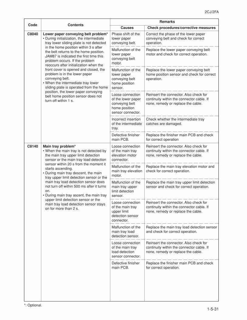
2CJ/2FA
1-5-31
Code ContentsRemarks
Causes Check procedures/corrective measures
Correct the phase of the lower paperconveying belt and check for correctoperation.
Replace the lower paper conveying beltmotor and check for correct operation.
Replace the lower paper conveying belthome position sensor and check for correctoperation.
Reinsert the connector. Also check forcontinuity within the connector cable. Ifnone, remedy or replace the cable.
Check whether the intermediate traycatches are damaged.
Replace the finisher main PCB and checkfor correct operation
Reinsert the connector. Also check forcontinuity within the connector cable. Ifnone, remedy or replace the cable.
Replace the main tray elevation motor andcheck for correct operation.
Replace the main tray upper limit detectionsensor and check for correct operation.
Reinsert the connector. Also check forcontinuity within the connector cable. Ifnone, remedy or replace the cable.
Replace the main tray load detection sensorand check for correct operation.
Reinsert the connector. Also check forcontinuity within the connector cable. Ifnone, remedy or replace the cable.
Replace the finisher main PCB and checkfor correct operation.
C8040 Lower paper conveying belt problem*• During initialization, the intermediate
tray lower sliding plate is not detectedin the home position within 3 s afterthe belt returns to the home position.JAM87 is indicated the first time thisproblem occurs. If the problemreoccurs after initialization when thefront cover is opened and closed, theproblem is in the lower paperconveying belt.
• When the intermediate tray lowersliding plate is operated from the homeposition, the lower paper conveyingbelt home position sensor does notturn off within 1 s.
C8140 Main tray problem*• When the main tray is not detected by
the main tray upper limit detectionsensor or the main tray load detectionsensor within 20 s from the moment itstarts ascending.
• During main tray descent, the maintray upper limit detection sensor or themain tray load detection sensor doesnot turn off within 500 ms after it turnson.
• During main tray ascent, the main trayupper limit detection sensor or themain tray load detection sensor stayson for more than 2 s.
Phase shift of thelower paperconveying belt.
Malfunction of thelower paperconveying beltmotor.
Malfunction of thelower paperconveying belthome positionsensor.
Loose connectionof the lower paperconveying belthome positionsensor connector.
Incorrect insertionof the intermediatetray.
Defective finishermain PCB.
Loose connectionof the main trayelevation motorconnector.
Malfunction of themain tray elevationmotor.
Malfunction of themain tray upperlimit detectionsensor.
Loose connectionof the main trayupper limitdetection sensorconnector.
Malfunction of themain tray loaddetection sensor.
Loose connectionof the main trayload detectionsensor connector.
Defective finishermain PCB.
*: Optional.
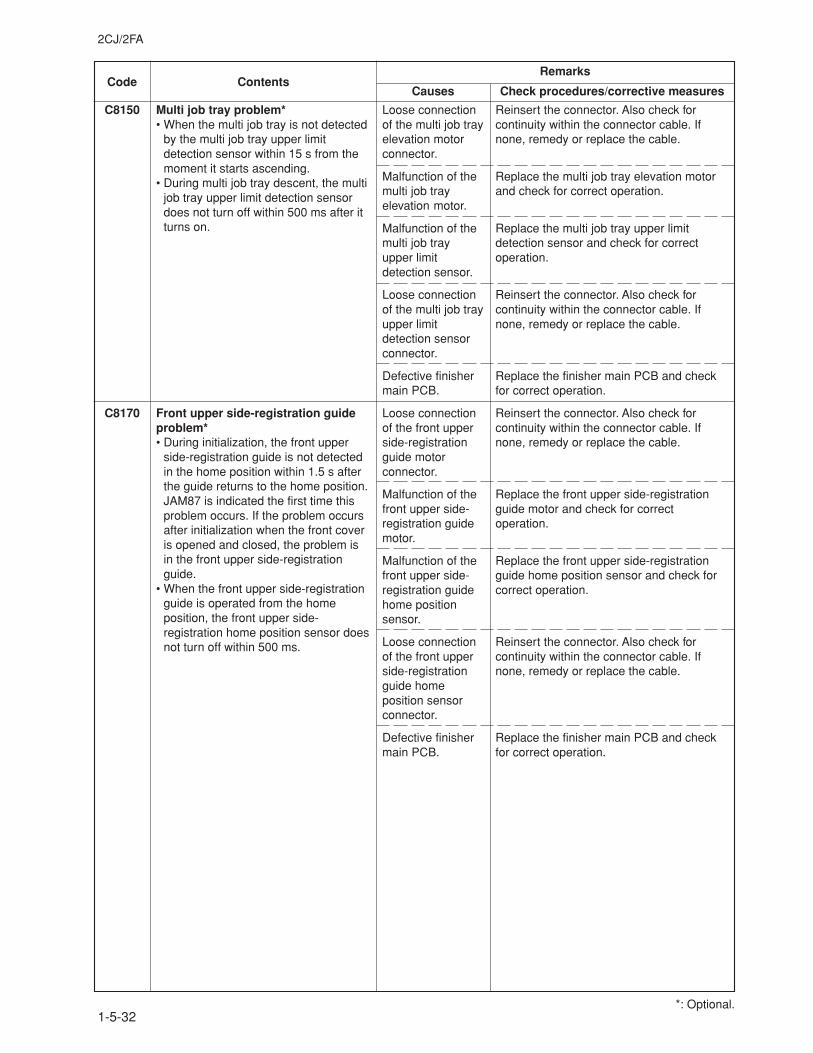
2CJ/2FA
1-5-32
Code ContentsRemarks
Causes Check procedures/corrective measures
C8150 Multi job tray problem*• When the multi job tray is not detected
by the multi job tray upper limitdetection sensor within 15 s from themoment it starts ascending.
• During multi job tray descent, the multijob tray upper limit detection sensordoes not turn off within 500 ms after itturns on.
C8170 Front upper side-registration guideproblem*• During initialization, the front upper
side-registration guide is not detectedin the home position within 1.5 s afterthe guide returns to the home position.JAM87 is indicated the first time thisproblem occurs. If the problem occursafter initialization when the front coveris opened and closed, the problem isin the front upper side-registrationguide.
• When the front upper side-registrationguide is operated from the homeposition, the front upper side-registration home position sensor doesnot turn off within 500 ms.
Loose connectionof the multi job trayelevation motorconnector.
Malfunction of themulti job trayelevation motor.
Malfunction of themulti job trayupper limitdetection sensor.
Loose connectionof the multi job trayupper limitdetection sensorconnector.
Defective finishermain PCB.
Loose connectionof the front upperside-registrationguide motorconnector.
Malfunction of thefront upper side-registration guidemotor.
Malfunction of thefront upper side-registration guidehome positionsensor.
Loose connectionof the front upperside-registrationguide homeposition sensorconnector.
Defective finishermain PCB.
Reinsert the connector. Also check forcontinuity within the connector cable. Ifnone, remedy or replace the cable.
Replace the multi job tray elevation motorand check for correct operation.
Replace the multi job tray upper limitdetection sensor and check for correctoperation.
Reinsert the connector. Also check forcontinuity within the connector cable. Ifnone, remedy or replace the cable.
Replace the finisher main PCB and checkfor correct operation.
Reinsert the connector. Also check forcontinuity within the connector cable. Ifnone, remedy or replace the cable.
Replace the front upper side-registrationguide motor and check for correctoperation.
Replace the front upper side-registrationguide home position sensor and check forcorrect operation.
Reinsert the connector. Also check forcontinuity within the connector cable. Ifnone, remedy or replace the cable.
Replace the finisher main PCB and checkfor correct operation.
*: Optional.
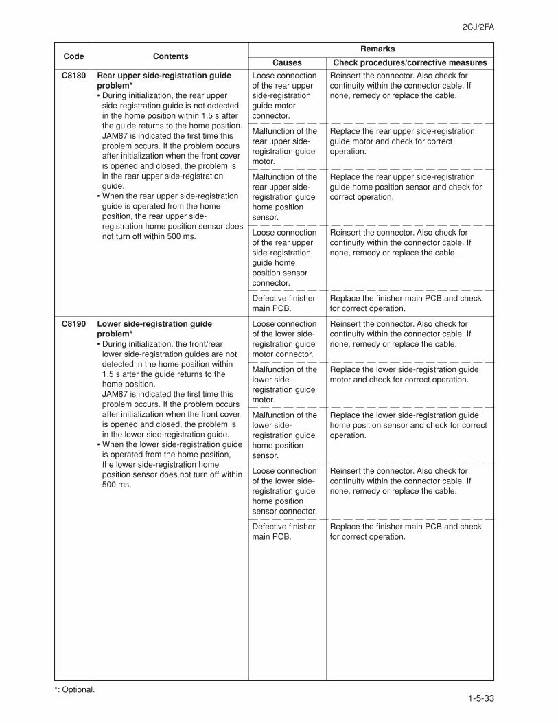
2CJ/2FA
1-5-33
Code ContentsRemarks
Causes Check procedures/corrective measures
C8180 Rear upper side-registration guideproblem*• During initialization, the rear upper
side-registration guide is not detectedin the home position within 1.5 s afterthe guide returns to the home position.JAM87 is indicated the first time thisproblem occurs. If the problem occursafter initialization when the front coveris opened and closed, the problem isin the rear upper side-registrationguide.
• When the rear upper side-registrationguide is operated from the homeposition, the rear upper side-registration home position sensor doesnot turn off within 500 ms.
C8190 Lower side-registration guideproblem*• During initialization, the front/rear
lower side-registration guides are notdetected in the home position within1.5 s after the guide returns to thehome position.JAM87 is indicated the first time thisproblem occurs. If the problem occursafter initialization when the front coveris opened and closed, the problem isin the lower side-registration guide.
• When the lower side-registration guideis operated from the home position,the lower side-registration homeposition sensor does not turn off within500 ms.
Loose connectionof the rear upperside-registrationguide motorconnector.
Malfunction of therear upper side-registration guidemotor.
Malfunction of therear upper side-registration guidehome positionsensor.
Loose connectionof the rear upperside-registrationguide homeposition sensorconnector.
Defective finishermain PCB.
Loose connectionof the lower side-registration guidemotor connector.
Malfunction of thelower side-registration guidemotor.
Malfunction of thelower side-registration guidehome positionsensor.
Loose connectionof the lower side-registration guidehome positionsensor connector.
Defective finishermain PCB.
Reinsert the connector. Also check forcontinuity within the connector cable. Ifnone, remedy or replace the cable.
Replace the rear upper side-registrationguide motor and check for correctoperation.
Replace the rear upper side-registrationguide home position sensor and check forcorrect operation.
Reinsert the connector. Also check forcontinuity within the connector cable. Ifnone, remedy or replace the cable.
Replace the finisher main PCB and checkfor correct operation.
Reinsert the connector. Also check forcontinuity within the connector cable. Ifnone, remedy or replace the cable.
Replace the lower side-registration guidemotor and check for correct operation.
Replace the lower side-registration guidehome position sensor and check for correctoperation.
Reinsert the connector. Also check forcontinuity within the connector cable. Ifnone, remedy or replace the cable.
Replace the finisher main PCB and checkfor correct operation.
*: Optional.
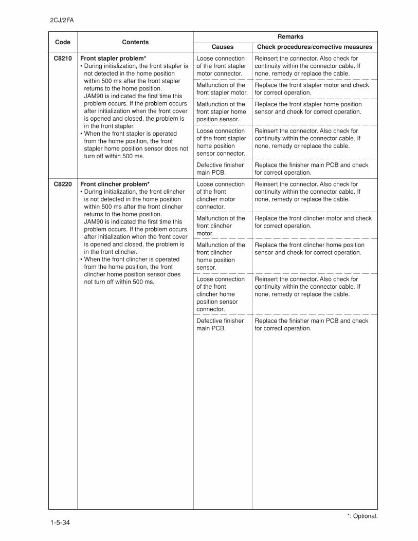
2CJ/2FA
1-5-34
Code ContentsRemarks
Causes Check procedures/corrective measures
C8210 Front stapler problem*• During initialization, the front stapler is
not detected in the home positionwithin 500 ms after the front staplerreturns to the home position.JAM90 is indicated the first time thisproblem occurs. If the problem occursafter initialization when the front coveris opened and closed, the problem isin the front stapler.
• When the front stapler is operatedfrom the home position, the frontstapler home position sensor does notturn off within 500 ms.
C8220 Front clincher problem*• During initialization, the front clincher
is not detected in the home positionwithin 500 ms after the front clincherreturns to the home position.JAM90 is indicated the first time thisproblem occurs. If the problem occursafter initialization when the front coveris opened and closed, the problem isin the front clincher.
• When the front clincher is operatedfrom the home position, the frontclincher home position sensor doesnot turn off within 500 ms.
Loose connectionof the front staplermotor connector.
Malfunction of thefront stapler motor.
Malfunction of thefront stapler homeposition sensor.
Loose connectionof the front staplerhome positionsensor connector.
Defective finishermain PCB.
Loose connectionof the frontclincher motorconnector.
Malfunction of thefront clinchermotor.
Malfunction of thefront clincherhome positionsensor.
Loose connectionof the frontclincher homeposition sensorconnector.
Defective finishermain PCB.
Reinsert the connector. Also check forcontinuity within the connector cable. Ifnone, remedy or replace the cable.
Replace the front stapler motor and checkfor correct operation.
Replace the front stapler home positionsensor and check for correct operation.
Reinsert the connector. Also check forcontinuity within the connector cable. Ifnone, remedy or replace the cable.
Replace the finisher main PCB and checkfor correct operation.
Reinsert the connector. Also check forcontinuity within the connector cable. Ifnone, remedy or replace the cable.
Replace the front clincher motor and checkfor correct operation.
Replace the front clincher home positionsensor and check for correct operation.
Reinsert the connector. Also check forcontinuity within the connector cable. Ifnone, remedy or replace the cable.
Replace the finisher main PCB and checkfor correct operation.
*: Optional.
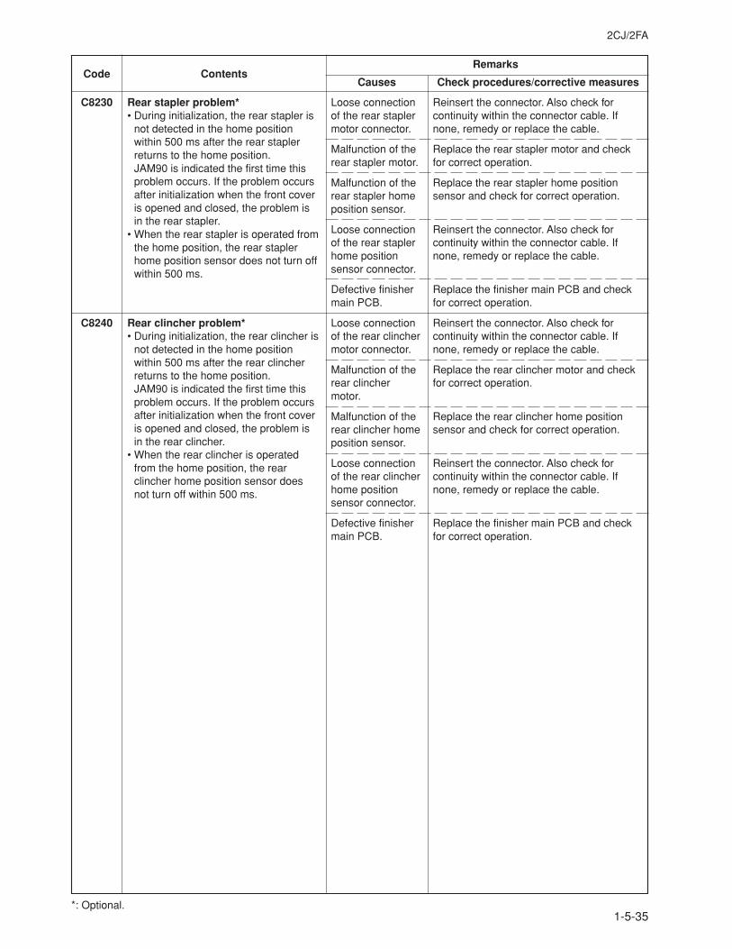
2CJ/2FA
1-5-35
Code ContentsRemarks
Causes Check procedures/corrective measures
C8230 Rear stapler problem*• During initialization, the rear stapler is
not detected in the home positionwithin 500 ms after the rear staplerreturns to the home position.JAM90 is indicated the first time thisproblem occurs. If the problem occursafter initialization when the front coveris opened and closed, the problem isin the rear stapler.
• When the rear stapler is operated fromthe home position, the rear staplerhome position sensor does not turn offwithin 500 ms.
C8240 Rear clincher problem*• During initialization, the rear clincher is
not detected in the home positionwithin 500 ms after the rear clincherreturns to the home position.JAM90 is indicated the first time thisproblem occurs. If the problem occursafter initialization when the front coveris opened and closed, the problem isin the rear clincher.
• When the rear clincher is operatedfrom the home position, the rearclincher home position sensor doesnot turn off within 500 ms.
Loose connectionof the rear staplermotor connector.
Malfunction of therear stapler motor.
Malfunction of therear stapler homeposition sensor.
Loose connectionof the rear staplerhome positionsensor connector.
Defective finishermain PCB.
Loose connectionof the rear clinchermotor connector.
Malfunction of therear clinchermotor.
Malfunction of therear clincher homeposition sensor.
Loose connectionof the rear clincherhome positionsensor connector.
Defective finishermain PCB.
Reinsert the connector. Also check forcontinuity within the connector cable. Ifnone, remedy or replace the cable.
Replace the rear stapler motor and checkfor correct operation.
Replace the rear stapler home positionsensor and check for correct operation.
Reinsert the connector. Also check forcontinuity within the connector cable. Ifnone, remedy or replace the cable.
Replace the finisher main PCB and checkfor correct operation.
Reinsert the connector. Also check forcontinuity within the connector cable. Ifnone, remedy or replace the cable.
Replace the rear clincher motor and checkfor correct operation.
Replace the rear clincher home positionsensor and check for correct operation.
Reinsert the connector. Also check forcontinuity within the connector cable. Ifnone, remedy or replace the cable.
Replace the finisher main PCB and checkfor correct operation.
*: Optional.
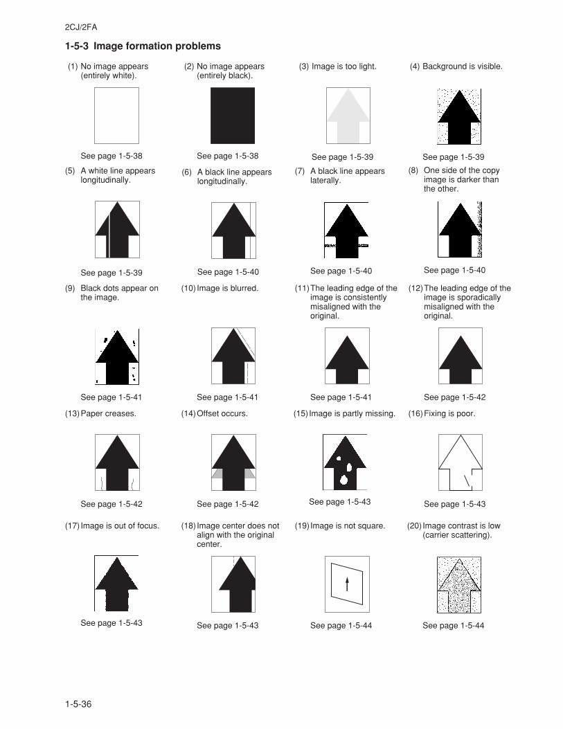
2CJ/2FA
1-5-36
1-5-3 Image formation problems
(20)Image contrast is low(carrier scattering).
See page 1-5-44
(1) No image appears(entirely white).
See page 1-5-38
(2) No image appears(entirely black).
See page 1-5-38
(3) Image is too light.
See page 1-5-39
(4) Background is visible.
See page 1-5-39
(5) A white line appearslongitudinally.
See page 1-5-39
(6) A black line appearslongitudinally.
See page 1-5-40
(7) A black line appearslaterally.
See page 1-5-40
(8) One side of the copyimage is darker thanthe other.
See page 1-5-40
(9) Black dots appear onthe image.
See page 1-5-41
(10) Image is blurred.
See page 1-5-41
(11)The leading edge of theimage is consistentlymisaligned with theoriginal.
See page 1-5-41
(12)The leading edge of theimage is sporadicallymisaligned with theoriginal.
See page 1-5-42
(13)Paper creases.
See page 1-5-42
(14)Offset occurs.
See page 1-5-42
(15)Image is partly missing.
See page 1-5-43
(16)Fixing is poor.
See page 1-5-43
(17) Image is out of focus.
See page 1-5-43
(18) Image center does notalign with the originalcenter.
See page 1-5-43
(19)Image is not square.
See page 1-5-44
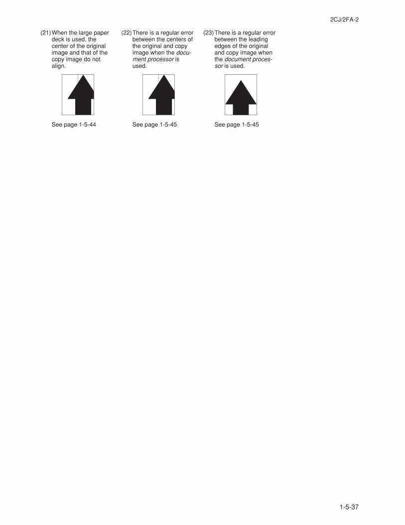
2CJ/2FA-2
1-5-37
(22)There is a regular errorbetween the centers ofthe original and copyimage when the docu-ment processor isused.
See page 1-5-45
(23)There is a regular errorbetween the leadingedges of the originaland copy image whenthe document proces-sor is used.
See page 1-5-45
(21)When the large paperdeck is used, thecenter of the originalimage and that of thecopy image do notalign.
See page 1-5-44
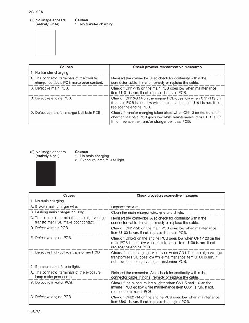
2CJ/2FA
1-5-38
(1) No image appears(entirely white).
Causes1. No transfer charging.
Causes Check procedures/corrective measures
1. No transfer charging.
A. The connector terminals of the transfercharger belt bais PCB make poor contact.
B. Defective main PCB.
C. Defective engine PCB.
D. Defective transfer charger belt bais PCB.
Reinsert the connector. Also check for continuity within theconnector cable. If none, remedy or replace the cable.
Check if CN1-119 on the main PCB goes low when maintenanceitem U101 is run. If not, replace the main PCB.
Check if CN13-A14 on the engine PCB goes low when CN1-119 onthe main PCB is held low while maintenance item U101 is run. If not,replace the engine PCB.
Check if transfer charging takes place when CN1-3 on the transfercharger belt bais PCB goes low while maintenance item U101 is run.If not, replace the transfer charger belt bais PCB.
Causes Check procedures/corrective measures
1. No main charging.
A. Broken main charger wire.
B. Leaking main charger housing.
C. The connector terminals of the high-voltagetransformer PCB make poor contact.
D. Defective main PCB.
E. Defective engine PCB.
F. Defective high-voltage transformer PCB.
2. Exposure lamp fails to light.
A. The connector terminals of the exposurelamp make poor contact.
B. Defective inverter PCB.
C. Defective engine PCB.
(2) No image appears(entirely black).
Causes1. No main charging.2. Exposure lamp fails to light.
Replace the wire.
Clean the main charger wire, grid and shield.
Reinsert the connector. Also check for continuity within theconnector cable. If none, remedy or replace the cable.
Check if CN1-120 on the main PCB goes low when maintenanceitem U100 is run. If not, replace the main PCB.
Check if CN5-3 on the engine PCB goes low when CN1-120 on themain PCB is held low while maintenance item U100 is run. If not,replace the engine PCB.
Check if main charging takes place when CN1-7 on the high-voltagetransformer PCB goes low while maintenance item U100 is run. Ifnot, replace the high-voltage transformer PCB.
Reinsert the connector. Also check for continuity within theconnector cable. If none, remedy or replace the cable.
Check if the exposure lamp lights when CN1-5 and 1-6 on theinverter PCB go low while maintenance item U061 is run. If not,replace the inverter PCB.
Check if CN21-14 on the engine PCB goes low when maintenanceitem U061 is run. If not, replace the engine PCB.
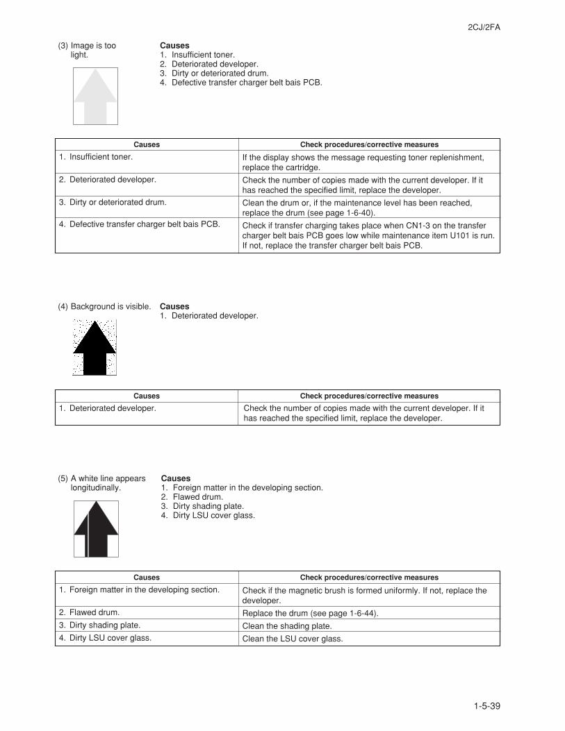
2CJ/2FA
1-5-39
Causes Check procedures/corrective measures
1. Foreign matter in the developing section.
2. Flawed drum.
3. Dirty shading plate.
4. Dirty LSU cover glass.
(5) A white line appearslongitudinally.
Causes1. Foreign matter in the developing section.2. Flawed drum.3. Dirty shading plate.4. Dirty LSU cover glass.
(3) Image is toolight.
(4) Background is visible.
Causes1. Insufficient toner.2. Deteriorated developer.3. Dirty or deteriorated drum.4. Defective transfer charger belt bais PCB.
Causes Check procedures/corrective measures
1. Insufficient toner.
2. Deteriorated developer.
3. Dirty or deteriorated drum.
4. Defective transfer charger belt bais PCB.
Causes1. Deteriorated developer.
Causes Check procedures/corrective measures
1. Deteriorated developer. Check the number of copies made with the current developer. If ithas reached the specified limit, replace the developer.
If the display shows the message requesting toner replenishment,replace the cartridge.
Check the number of copies made with the current developer. If ithas reached the specified limit, replace the developer.
Clean the drum or, if the maintenance level has been reached,replace the drum (see page 1-6-40).
Check if transfer charging takes place when CN1-3 on the transfercharger belt bais PCB goes low while maintenance item U101 is run.If not, replace the transfer charger belt bais PCB.
Check if the magnetic brush is formed uniformly. If not, replace thedeveloper.
Replace the drum (see page 1-6-44).
Clean the shading plate.
Clean the LSU cover glass.
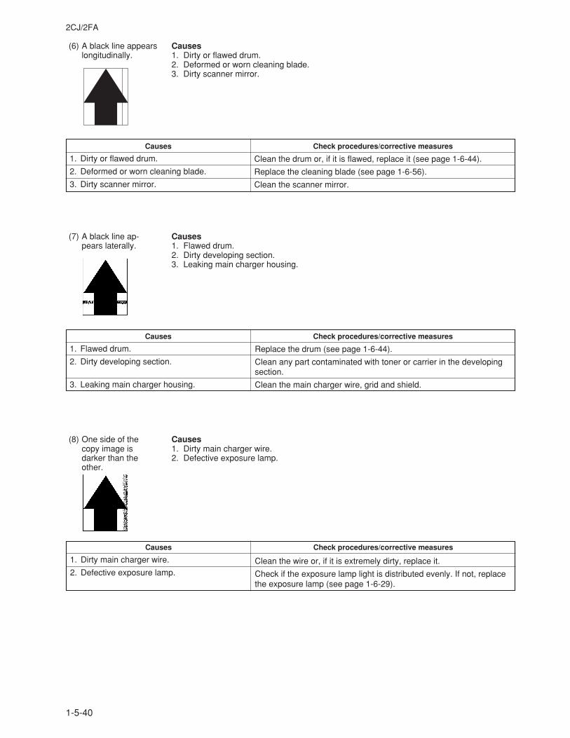
2CJ/2FA
1-5-40
Causes Check procedures/corrective measures
1. Dirty or flawed drum.
2. Deformed or worn cleaning blade.
3. Dirty scanner mirror.
(6) A black line appearslongitudinally.
Causes1. Dirty or flawed drum.2. Deformed or worn cleaning blade.3. Dirty scanner mirror.
Clean the drum or, if it is flawed, replace it (see page 1-6-44).
Replace the cleaning blade (see page 1-6-56).
Clean the scanner mirror.
Causes Check procedures/corrective measures
1. Dirty main charger wire.
2. Defective exposure lamp.
Causes Check procedures/corrective measures
1. Flawed drum.
2. Dirty developing section.
3. Leaking main charger housing.
(7) A black line ap-pears laterally.
Causes1. Flawed drum.2. Dirty developing section.3. Leaking main charger housing.
(8) One side of thecopy image isdarker than theother.
Causes1. Dirty main charger wire.2. Defective exposure lamp.
Replace the drum (see page 1-6-44).
Clean any part contaminated with toner or carrier in the developingsection.
Clean the main charger wire, grid and shield.
Clean the wire or, if it is extremely dirty, replace it.
Check if the exposure lamp light is distributed evenly. If not, replacethe exposure lamp (see page 1-6-29).
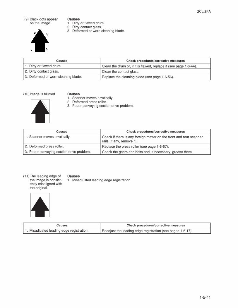
2CJ/2FA
1-5-41
(11)The leading edge ofthe image is consist-ently misaligned withthe original.
Causes1. Misadjusted leading edge registration.
Causes Check procedures/corrective measures
1. Misadjusted leading edge registration.
(10)Image is blurred.
(9) Black dots appearon the image.
Causes1. Dirty or flawed drum.2. Dirty contact glass.3. Deformed or worn cleaning blade.
Causes Check procedures/corrective measures
1. Dirty or flawed drum.
2. Dirty contact glass.
3. Deformed or worn cleaning blade.
Causes1. Scanner moves erratically.2. Deformed press roller.3. Paper conveying section drive problem.
Causes Check procedures/corrective measures
1. Scanner moves erratically.
2. Deformed press roller.
3. Paper conveying section drive problem.
Check if there is any foreign matter on the front and rear scannerrails. If any, remove it.
Replace the press roller (see page 1-6-67).
Check the gears and belts and, if necessary, grease them.
Readjust the leading edge registration (see pages 1-6-17).
Clean the drum or, if it is flawed, replace it (see page 1-6-44).
Clean the contact glass.
Replace the cleaning blade (see page 1-6-56).
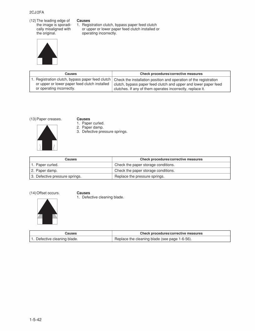
2CJ/2FA
1-5-42
(12)The leading edge ofthe image is sporadi-cally misaligned withthe original.
Causes1. Registration clutch, bypass paper feed clutch
or upper or lower paper feed clutch installed oroperating incorrectly.
Causes Check procedures/corrective measures
1. Registration clutch, bypass paper feed clutchor upper or lower paper feed clutch installedor operating incorrectly.
Check the installation position and operation of the registrationclutch, bypass paper feed clutch and upper and lower paper feedclutches. If any of them operates incorrectly, replace it.
(14)Offset occurs.
(13)Paper creases. Causes1. Paper curled.2. Paper damp.3. Defective pressure springs.
Causes Check procedures/corrective measures
1. Paper curled. Check the paper storage conditions.
2. Paper damp. Check the paper storage conditions.
3. Defective pressure springs. Replace the pressure springs.
Causes1. Defective cleaning blade.
Causes Check procedures/corrective measures
1. Defective cleaning blade. Replace the cleaning blade (see page 1-6-56).
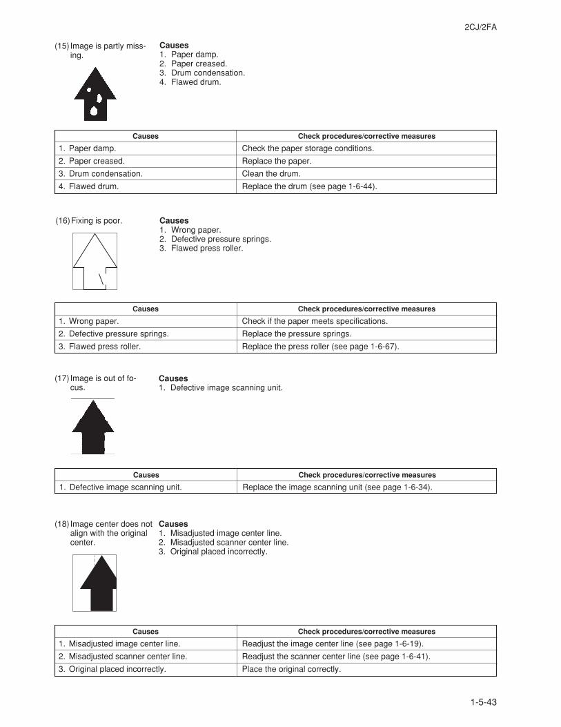
2CJ/2FA
1-5-43
Causes Check procedures/corrective measures
1. Misadjusted image center line. Readjust the image center line (see page 1-6-19).
2. Misadjusted scanner center line. Readjust the scanner center line (see page 1-6-41).
3. Original placed incorrectly. Place the original correctly.
(18) Image center does notalign with the originalcenter.
(17) Image is out of fo-cus.
Causes1. Defective image scanning unit.
Causes Check procedures/corrective measures
1. Defective image scanning unit. Replace the image scanning unit (see page 1-6-34).
Causes1. Misadjusted image center line.2. Misadjusted scanner center line.3. Original placed incorrectly.
(15) Image is partly miss-ing.
Causes1. Paper damp.2. Paper creased.3. Drum condensation.4. Flawed drum.
Causes Check procedures/corrective measures
1. Paper damp. Check the paper storage conditions.
2. Paper creased. Replace the paper.
3. Drum condensation. Clean the drum.
4. Flawed drum. Replace the drum (see page 1-6-44).
(16)Fixing is poor. Causes1. Wrong paper.2. Defective pressure springs.3. Flawed press roller.
Causes Check procedures/corrective measures
1. Wrong paper. Check if the paper meets specifications.
2. Defective pressure springs. Replace the pressure springs.
3. Flawed press roller. Replace the press roller (see page 1-6-67).
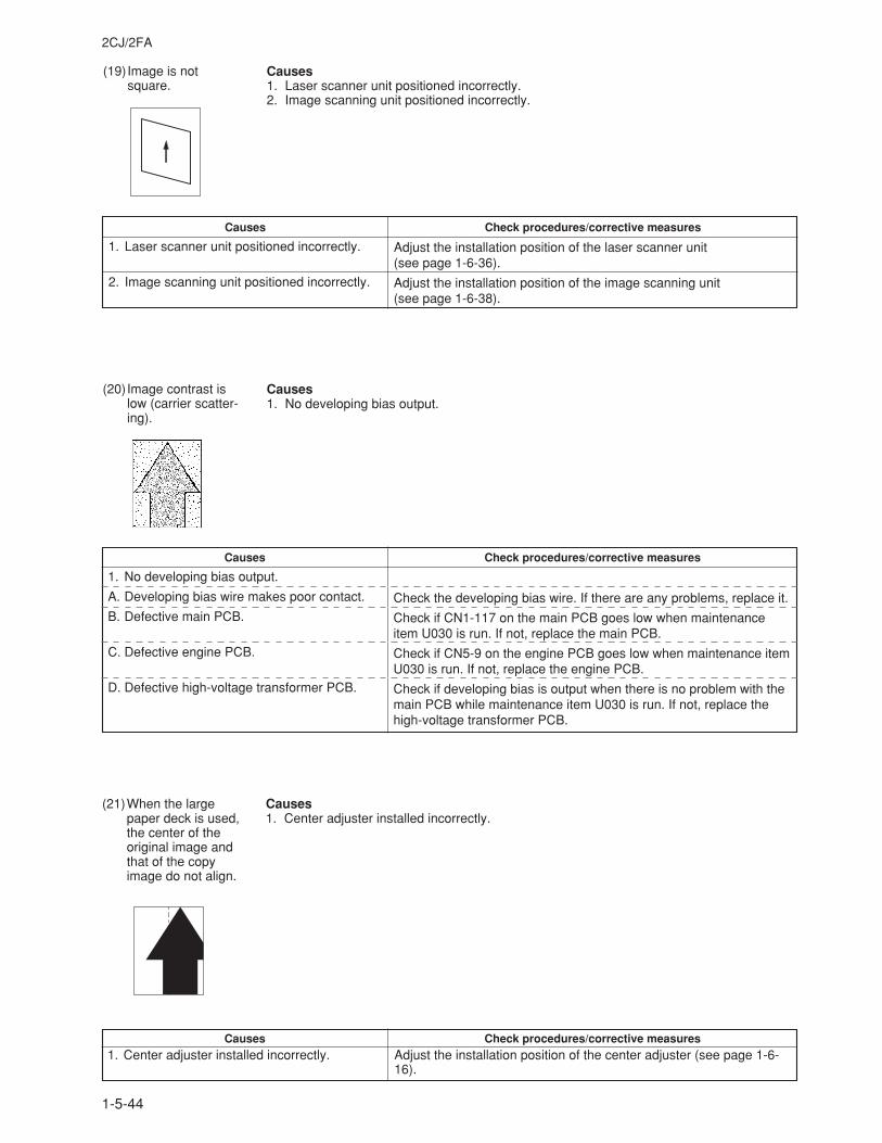
2CJ/2FA
1-5-44
(19)Image is notsquare.
Causes1. Laser scanner unit positioned incorrectly.2. Image scanning unit positioned incorrectly.
Causes Check procedures/corrective measures
1. Laser scanner unit positioned incorrectly.
2. Image scanning unit positioned incorrectly.
(20)Image contrast islow (carrier scatter-ing).
Causes1. No developing bias output.
Causes Check procedures/corrective measures
1. No developing bias output.
A. Developing bias wire makes poor contact.
B. Defective main PCB.
C. Defective engine PCB.
D. Defective high-voltage transformer PCB.
Adjust the installation position of the laser scanner unit(see page 1-6-36).
Adjust the installation position of the image scanning unit(see page 1-6-38).
Check the developing bias wire. If there are any problems, replace it.
Check if CN1-117 on the main PCB goes low when maintenanceitem U030 is run. If not, replace the main PCB.
Check if CN5-9 on the engine PCB goes low when maintenance itemU030 is run. If not, replace the engine PCB.
Check if developing bias is output when there is no problem with themain PCB while maintenance item U030 is run. If not, replace thehigh-voltage transformer PCB.
Check procedures/corrective measuresAdjust the installation position of the center adjuster (see page 1-6-16).
Causes1. Center adjuster installed incorrectly.
(21)When the largepaper deck is used,the center of theoriginal image andthat of the copyimage do not align.
Causes1. Center adjuster installed incorrectly.
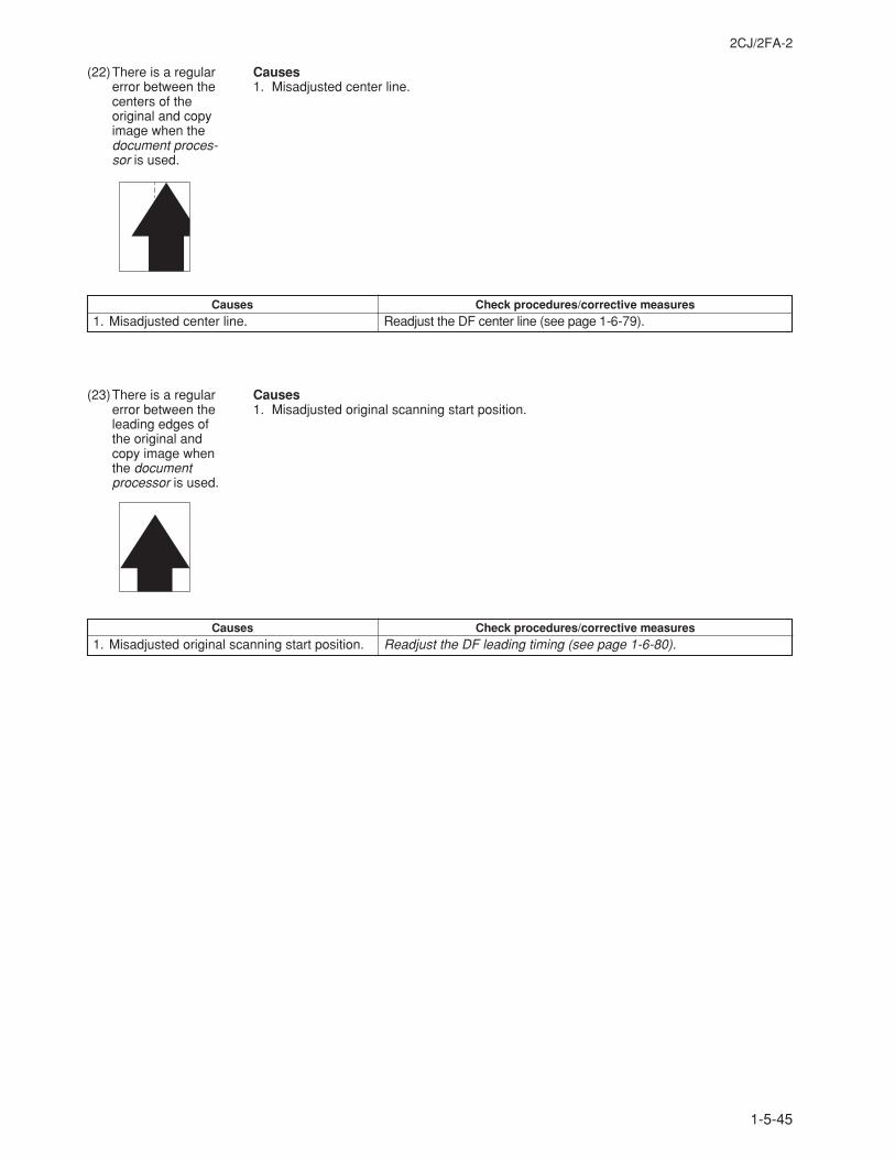
2CJ/2FA-2
1-5-45
(23)There is a regularerror between theleading edges ofthe original andcopy image whenthe documentprocessor is used.
Causes1. Misadjusted original scanning start position.
Check procedures/corrective measuresReadjust the DF leading timing (see page 1-6-80).
Causes1. Misadjusted original scanning start position.
(22)There is a regularerror between thecenters of theoriginal and copyimage when thedocument proces-sor is used.
Causes1. Misadjusted center line.
Check procedures/corrective measuresReadjust the DF center line (see page 1-6-79).
Causes1. Misadjusted center line.
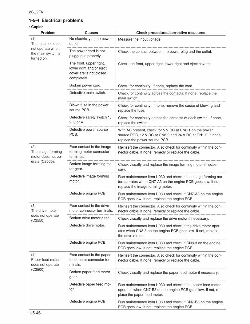
2CJ/2FA
1-5-46
Measure the input voltage.
Check the contact between the power plug and the outlet.
Check the front, upper right, lower right and eject covers.
Check for continuity. If none, replace the cord.
Check for continuity across the contacts. If none, replace themain switch.
Check for continuity. If none, remove the cause of blowing andreplace the fuse.
Check for continuity across the contacts of each switch. If none,replace the switch.
With AC present, check for 5 V DC at CN8-1 on the powersource PCB, 12 V DC at CN8-9 and 24 V DC at CN1-2. If none,replace the power source PCB.
Reinsert the connector. Also check for continuity within the con-nector cable. If none, remedy or replace the cable.
Check visually and replace the image forming motor if neces-sary.
Run maintenance item U030 and check if the image forming mo-tor operates when CN7-A3 on the engine PCB goes low. If not,replace the image forming motor.
Run maintenance item U030 and check if CN7-A3 on the enginePCB goes low. If not, replace the engine PCB.
Reinsert the connector. Also check for continuity within the con-nector cable. If none, remedy or replace the cable.
Check visually and replace the drive motor if necessary.
Run maintenance item U030 and check if the drive motor oper-ates when CN8-3 on the engine PCB goes low. If not, replacethe drive motor.
Run maintenance item U030 and check if CN8-3 on the enginePCB goes low. If not, replace the engine PCB.
Reinsert the connector. Also check for continuity within the con-nector cable. If none, remedy or replace the cable.
Check visually and replace the paper feed motor if necessary.
Run maintenance item U030 and check if the paper feed motoroperates when CN7-B3 on the engine PCB goes low. If not, re-place the paper feed motor.
Run maintenance item U030 and check if CN7-B3 on the enginePCB goes low. If not, replace the engine PCB.
(1)The machine doesnot operate whenthe main switch isturned on.
(2)The image formingmotor does not op-erate (C2000).
(3)The drive motordoes not operate(C2550).
(4)Paper feed motordoes not operate(C2500).
No electricity at the poweroutlet.
The power cord is notplugged in properly.
The front, upper right,lower right and/or ejectcover are/is not closedcompletely.
Broken power cord.
Defective main switch.
Blown fuse in the powersource PCB.
Defective safety switch 1,2, 3 or 4.
Defective power sourcePCB.
Poor contact in the imageforming motor connectorterminals.
Broken image forming mo-tor gear.
Defective image formingmotor.
Defective engine PCB.
Poor contact in the drivemotor connector terminals.
Broken drive motor gear.
Defective drive motor.
Defective engine PCB.
Poor contact in the paperfeed motor connector ter-minals.
Broken paper feed motorgear.
Defective paper feed mo-tor.
Defective engine PCB.
1-5-4 Electrical problems• Copier
Problem Causes Check procedures/corrective measures
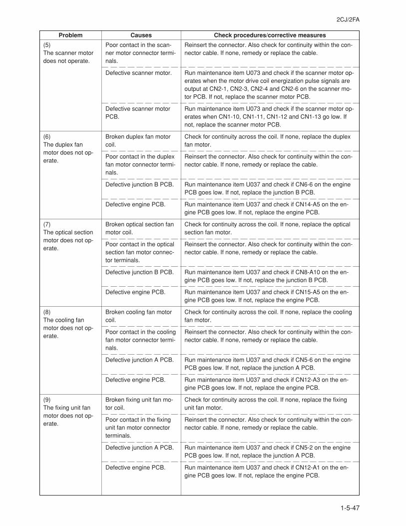
2CJ/2FA
1-5-47
Problem Causes Check procedures/corrective measures
(5)The scanner motordoes not operate.
(6)The duplex fanmotor does not op-erate.
(7)The optical sectionmotor does not op-erate.
(8)The cooling fanmotor does not op-erate.
(9)The fixing unit fanmotor does not op-erate.
Poor contact in the scan-ner motor connector termi-nals.
Defective scanner motor.
Defective scanner motorPCB.
Broken duplex fan motorcoil.
Poor contact in the duplexfan motor connector termi-nals.
Defective junction B PCB.
Defective engine PCB.
Broken optical section fanmotor coil.
Poor contact in the opticalsection fan motor connec-tor terminals.
Defective junction B PCB.
Defective engine PCB.
Broken cooling fan motorcoil.
Poor contact in the coolingfan motor connector termi-nals.
Defective junction A PCB.
Defective engine PCB.
Broken fixing unit fan mo-tor coil.
Poor contact in the fixingunit fan motor connectorterminals.
Defective junction A PCB.
Defective engine PCB.
Reinsert the connector. Also check for continuity within the con-nector cable. If none, remedy or replace the cable.
Run maintenance item U073 and check if the scanner motor op-erates when the motor drive coil energization pulse signals areoutput at CN2-1, CN2-3, CN2-4 and CN2-6 on the scanner mo-tor PCB. If not, replace the scanner motor PCB.
Run maintenance item U073 and check if the scanner motor op-erates when CN1-10, CN1-11, CN1-12 and CN1-13 go low. Ifnot, replace the scanner motor PCB.
Check for continuity across the coil. If none, replace the duplexfan motor.
Reinsert the connector. Also check for continuity within the con-nector cable. If none, remedy or replace the cable.
Run maintenance item U037 and check if CN6-6 on the enginePCB goes low. If not, replace the junction B PCB.
Run maintenance item U037 and check if CN14-A5 on the en-gine PCB goes low. If not, replace the engine PCB.
Check for continuity across the coil. If none, replace the opticalsection fan motor.
Reinsert the connector. Also check for continuity within the con-nector cable. If none, remedy or replace the cable.
Run maintenance item U037 and check if CN8-A10 on the en-gine PCB goes low. If not, replace the junction B PCB.
Run maintenance item U037 and check if CN15-A5 on the en-gine PCB goes low. If not, replace the engine PCB.
Check for continuity across the coil. If none, replace the coolingfan motor.
Reinsert the connector. Also check for continuity within the con-nector cable. If none, remedy or replace the cable.
Run maintenance item U037 and check if CN5-6 on the enginePCB goes low. If not, replace the junction A PCB.
Run maintenance item U037 and check if CN12-A3 on the en-gine PCB goes low. If not, replace the engine PCB.
Check for continuity across the coil. If none, replace the fixingunit fan motor.
Reinsert the connector. Also check for continuity within the con-nector cable. If none, remedy or replace the cable.
Run maintenance item U037 and check if CN5-2 on the enginePCB goes low. If not, replace the junction A PCB.
Run maintenance item U037 and check if CN12-A1 on the en-gine PCB goes low. If not, replace the engine PCB.
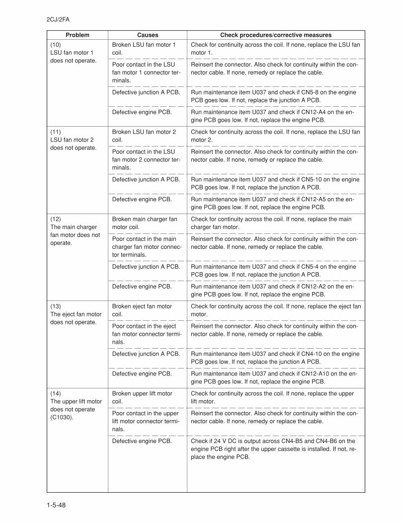
2CJ/2FA
1-5-48
Problem Causes Check procedures/corrective measures
Broken LSU fan motor 1coil.
Poor contact in the LSUfan motor 1 connector ter-minals.
Defective junction A PCB.
Defective engine PCB.
Broken LSU fan motor 2coil.
Poor contact in the LSUfan motor 2 connector ter-minals.
Defective junction A PCB.
Defective engine PCB.
Broken main charger fanmotor coil.
Poor contact in the maincharger fan motor connec-tor terminals.
Defective junction A PCB.
Defective engine PCB.
Broken eject fan motorcoil.
Poor contact in the ejectfan motor connector termi-nals.
Defective junction A PCB.
Defective engine PCB.
Broken upper lift motorcoil.
Poor contact in the upperlift motor connector termi-nals.
Defective engine PCB.
Check for continuity across the coil. If none, replace the LSU fanmotor 1.
Reinsert the connector. Also check for continuity within the con-nector cable. If none, remedy or replace the cable.
Run maintenance item U037 and check if CN5-8 on the enginePCB goes low. If not, replace the junction A PCB.
Run maintenance item U037 and check if CN12-A4 on the en-gine PCB goes low. If not, replace the engine PCB.
Check for continuity across the coil. If none, replace the LSU fanmotor 2.
Reinsert the connector. Also check for continuity within the con-nector cable. If none, remedy or replace the cable.
Run maintenance item U037 and check if CN5-10 on the enginePCB goes low. If not, replace the junction A PCB.
Run maintenance item U037 and check if CN12-A5 on the en-gine PCB goes low. If not, replace the engine PCB.
Check for continuity across the coil. If none, replace the maincharger fan motor.
Reinsert the connector. Also check for continuity within the con-nector cable. If none, remedy or replace the cable.
Run maintenance item U037 and check if CN5-4 on the enginePCB goes low. If not, replace the junction A PCB.
Run maintenance item U037 and check if CN12-A2 on the en-gine PCB goes low. If not, replace the engine PCB.
Check for continuity across the coil. If none, replace the eject fanmotor.
Reinsert the connector. Also check for continuity within the con-nector cable. If none, remedy or replace the cable.
Run maintenance item U037 and check if CN4-10 on the enginePCB goes low. If not, replace the junction A PCB.
Run maintenance item U037 and check if CN12-A10 on the en-gine PCB goes low. If not, replace the engine PCB.
Check for continuity across the coil. If none, replace the upperlift motor.
Reinsert the connector. Also check for continuity within the con-nector cable. If none, remedy or replace the cable.
Check if 24 V DC is output across CN4-B5 and CN4-B6 on theengine PCB right after the upper cassette is installed. If not, re-place the engine PCB.
(10)LSU fan motor 1does not operate.
(11)LSU fan motor 2does not operate.
(12)The main chargerfan motor does notoperate.
(13)The eject fan motordoes not operate.
(14)The upper lift motordoes not operate(C1030).
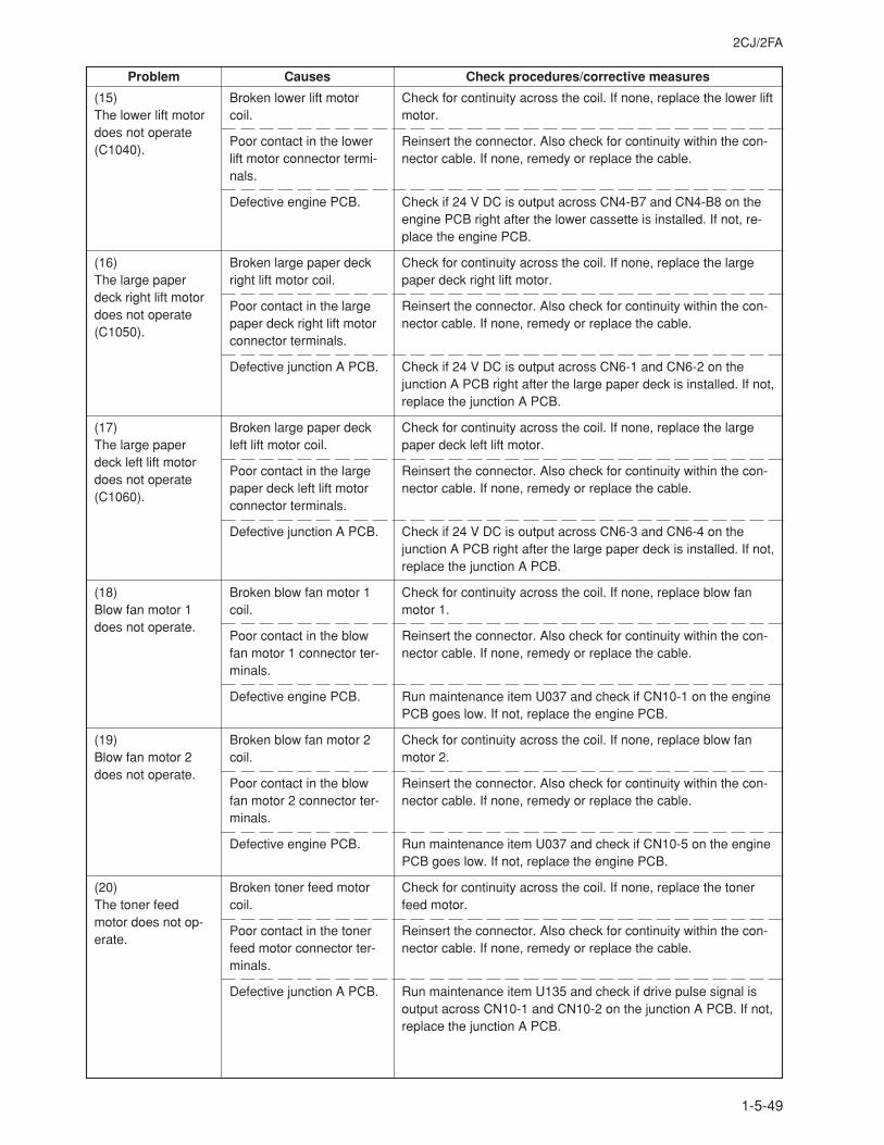
2CJ/2FA
1-5-49
Problem Causes Check procedures/corrective measures
Broken lower lift motorcoil.
Poor contact in the lowerlift motor connector termi-nals.
Defective engine PCB.
Broken large paper deckright lift motor coil.
Poor contact in the largepaper deck right lift motorconnector terminals.
Defective junction A PCB.
Broken large paper deckleft lift motor coil.
Poor contact in the largepaper deck left lift motorconnector terminals.
Defective junction A PCB.
Broken blow fan motor 1coil.
Poor contact in the blowfan motor 1 connector ter-minals.
Defective engine PCB.
Broken blow fan motor 2coil.
Poor contact in the blowfan motor 2 connector ter-minals.
Defective engine PCB.
Broken toner feed motorcoil.
Poor contact in the tonerfeed motor connector ter-minals.
Defective junction A PCB.
Check for continuity across the coil. If none, replace the lower liftmotor.
Reinsert the connector. Also check for continuity within the con-nector cable. If none, remedy or replace the cable.
Check if 24 V DC is output across CN4-B7 and CN4-B8 on theengine PCB right after the lower cassette is installed. If not, re-place the engine PCB.
Check for continuity across the coil. If none, replace the largepaper deck right lift motor.
Reinsert the connector. Also check for continuity within the con-nector cable. If none, remedy or replace the cable.
Check if 24 V DC is output across CN6-1 and CN6-2 on thejunction A PCB right after the large paper deck is installed. If not,replace the junction A PCB.
Check for continuity across the coil. If none, replace the largepaper deck left lift motor.
Reinsert the connector. Also check for continuity within the con-nector cable. If none, remedy or replace the cable.
Check if 24 V DC is output across CN6-3 and CN6-4 on thejunction A PCB right after the large paper deck is installed. If not,replace the junction A PCB.
Check for continuity across the coil. If none, replace blow fanmotor 1.
Reinsert the connector. Also check for continuity within the con-nector cable. If none, remedy or replace the cable.
Run maintenance item U037 and check if CN10-1 on the enginePCB goes low. If not, replace the engine PCB.
Check for continuity across the coil. If none, replace blow fanmotor 2.
Reinsert the connector. Also check for continuity within the con-nector cable. If none, remedy or replace the cable.
Run maintenance item U037 and check if CN10-5 on the enginePCB goes low. If not, replace the engine PCB.
Check for continuity across the coil. If none, replace the tonerfeed motor.
Reinsert the connector. Also check for continuity within the con-nector cable. If none, remedy or replace the cable.
Run maintenance item U135 and check if drive pulse signal isoutput across CN10-1 and CN10-2 on the junction A PCB. If not,replace the junction A PCB.
(15)The lower lift motordoes not operate(C1040).
(16)The large paperdeck right lift motordoes not operate(C1050).
(17)The large paperdeck left lift motordoes not operate(C1060).
(18)Blow fan motor 1does not operate.
(19)Blow fan motor 2does not operate.
(20)The toner feedmotor does not op-erate.
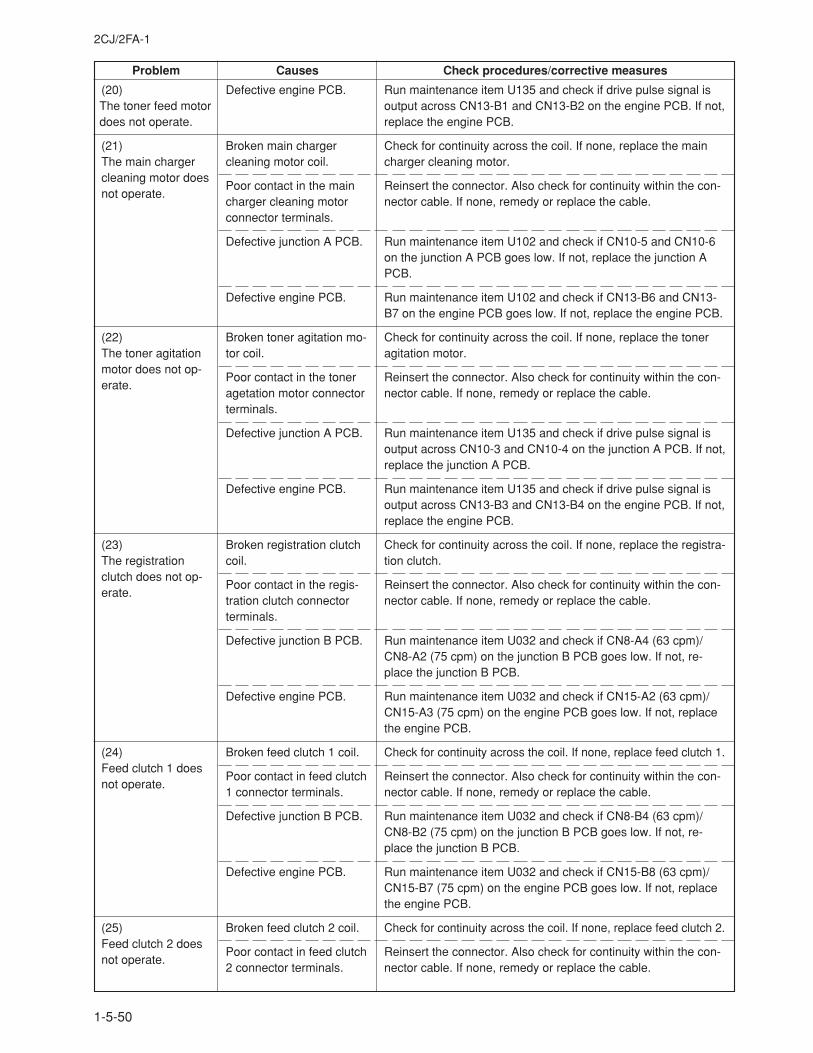
2CJ/2FA-1
1-5-50
Problem Causes Check procedures/corrective measures
Defective engine PCB.
Broken main chargercleaning motor coil.
Poor contact in the maincharger cleaning motorconnector terminals.
Defective junction A PCB.
Defective engine PCB.
Broken toner agitation mo-tor coil.
Poor contact in the toneragetation motor connectorterminals.
Defective junction A PCB.
Defective engine PCB.
Broken registration clutchcoil.
Poor contact in the regis-tration clutch connectorterminals.
Defective junction B PCB.
Defective engine PCB.
Broken feed clutch 1 coil.
Poor contact in feed clutch1 connector terminals.
Defective junction B PCB.
Defective engine PCB.
Broken feed clutch 2 coil.
Poor contact in feed clutch2 connector terminals.
Run maintenance item U135 and check if drive pulse signal isoutput across CN13-B1 and CN13-B2 on the engine PCB. If not,replace the engine PCB.
Check for continuity across the coil. If none, replace the maincharger cleaning motor.
Reinsert the connector. Also check for continuity within the con-nector cable. If none, remedy or replace the cable.
Run maintenance item U102 and check if CN10-5 and CN10-6on the junction A PCB goes low. If not, replace the junction APCB.
Run maintenance item U102 and check if CN13-B6 and CN13-B7 on the engine PCB goes low. If not, replace the engine PCB.
Check for continuity across the coil. If none, replace the toneragitation motor.
Reinsert the connector. Also check for continuity within the con-nector cable. If none, remedy or replace the cable.
Run maintenance item U135 and check if drive pulse signal isoutput across CN10-3 and CN10-4 on the junction A PCB. If not,replace the junction A PCB.
Run maintenance item U135 and check if drive pulse signal isoutput across CN13-B3 and CN13-B4 on the engine PCB. If not,replace the engine PCB.
Check for continuity across the coil. If none, replace the registra-tion clutch.
Reinsert the connector. Also check for continuity within the con-nector cable. If none, remedy or replace the cable.
Run maintenance item U032 and check if CN8-A4 (63 cpm)/CN8-A2 (75 cpm) on the junction B PCB goes low. If not, re-place the junction B PCB.
Run maintenance item U032 and check if CN15-A2 (63 cpm)/CN15-A3 (75 cpm) on the engine PCB goes low. If not, replacethe engine PCB.
Check for continuity across the coil. If none, replace feed clutch 1.
Reinsert the connector. Also check for continuity within the con-nector cable. If none, remedy or replace the cable.
Run maintenance item U032 and check if CN8-B4 (63 cpm)/CN8-B2 (75 cpm) on the junction B PCB goes low. If not, re-place the junction B PCB.
Run maintenance item U032 and check if CN15-B8 (63 cpm)/CN15-B7 (75 cpm) on the engine PCB goes low. If not, replacethe engine PCB.
Check for continuity across the coil. If none, replace feed clutch 2.
Reinsert the connector. Also check for continuity within the con-nector cable. If none, remedy or replace the cable.
(20)The toner feed motordoes not operate.
(21)The main chargercleaning motor doesnot operate.
(22)The toner agitationmotor does not op-erate.
(23)The registrationclutch does not op-erate.
(24)Feed clutch 1 doesnot operate.
(25)Feed clutch 2 doesnot operate.
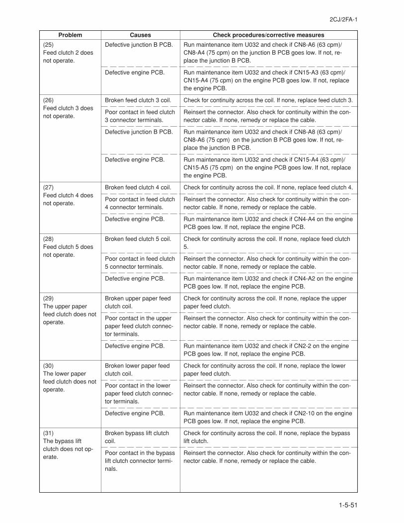
2CJ/2FA-1
1-5-51
Problem Causes Check procedures/corrective measures
Defective junction B PCB.
Defective engine PCB.
Broken feed clutch 3 coil.
Poor contact in feed clutch3 connector terminals.
Defective junction B PCB.
Defective engine PCB.
Broken feed clutch 4 coil.
Poor contact in feed clutch4 connector terminals.
Defective engine PCB.
Broken feed clutch 5 coil.
Poor contact in feed clutch5 connector terminals.
Defective engine PCB.
Broken upper paper feedclutch coil.
Poor contact in the upperpaper feed clutch connec-tor terminals.
Defective engine PCB.
Broken lower paper feedclutch coil.
Poor contact in the lowerpaper feed clutch connec-tor terminals.
Defective engine PCB.
Broken bypass lift clutchcoil.
Poor contact in the bypasslift clutch connector termi-nals.
Run maintenance item U032 and check if CN8-A6 (63 cpm)/CN8-A4 (75 cpm) on the junction B PCB goes low. If not, re-place the junction B PCB.
Run maintenance item U032 and check if CN15-A3 (63 cpm)/CN15-A4 (75 cpm) on the engine PCB goes low. If not, replacethe engine PCB.
Check for continuity across the coil. If none, replace feed clutch 3.
Reinsert the connector. Also check for continuity within the con-nector cable. If none, remedy or replace the cable.
Run maintenance item U032 and check if CN8-A8 (63 cpm)/CN8-A6 (75 cpm) on the junction B PCB goes low. If not, re-place the junction B PCB.
Run maintenance item U032 and check if CN15-A4 (63 cpm)/CN15-A5 (75 cpm) on the engine PCB goes low. If not, replacethe engine PCB.
Check for continuity across the coil. If none, replace feed clutch 4.
Reinsert the connector. Also check for continuity within the con-nector cable. If none, remedy or replace the cable.
Run maintenance item U032 and check if CN4-A4 on the enginePCB goes low. If not, replace the engine PCB.
Check for continuity across the coil. If none, replace feed clutch5.
Reinsert the connector. Also check for continuity within the con-nector cable. If none, remedy or replace the cable.
Run maintenance item U032 and check if CN4-A2 on the enginePCB goes low. If not, replace the engine PCB.
Check for continuity across the coil. If none, replace the upperpaper feed clutch.
Reinsert the connector. Also check for continuity within the con-nector cable. If none, remedy or replace the cable.
Run maintenance item U032 and check if CN2-2 on the enginePCB goes low. If not, replace the engine PCB.
Check for continuity across the coil. If none, replace the lowerpaper feed clutch.
Reinsert the connector. Also check for continuity within the con-nector cable. If none, remedy or replace the cable.
Run maintenance item U032 and check if CN2-10 on the enginePCB goes low. If not, replace the engine PCB.
Check for continuity across the coil. If none, replace the bypasslift clutch.
Reinsert the connector. Also check for continuity within the con-nector cable. If none, remedy or replace the cable.
(25)Feed clutch 2 doesnot operate.
(26)Feed clutch 3 doesnot operate.
(27)Feed clutch 4 doesnot operate.
(28)Feed clutch 5 doesnot operate.
(29)The upper paperfeed clutch does notoperate.
(30)The lower paperfeed clutch does notoperate.
(31)The bypass liftclutch does not op-erate.
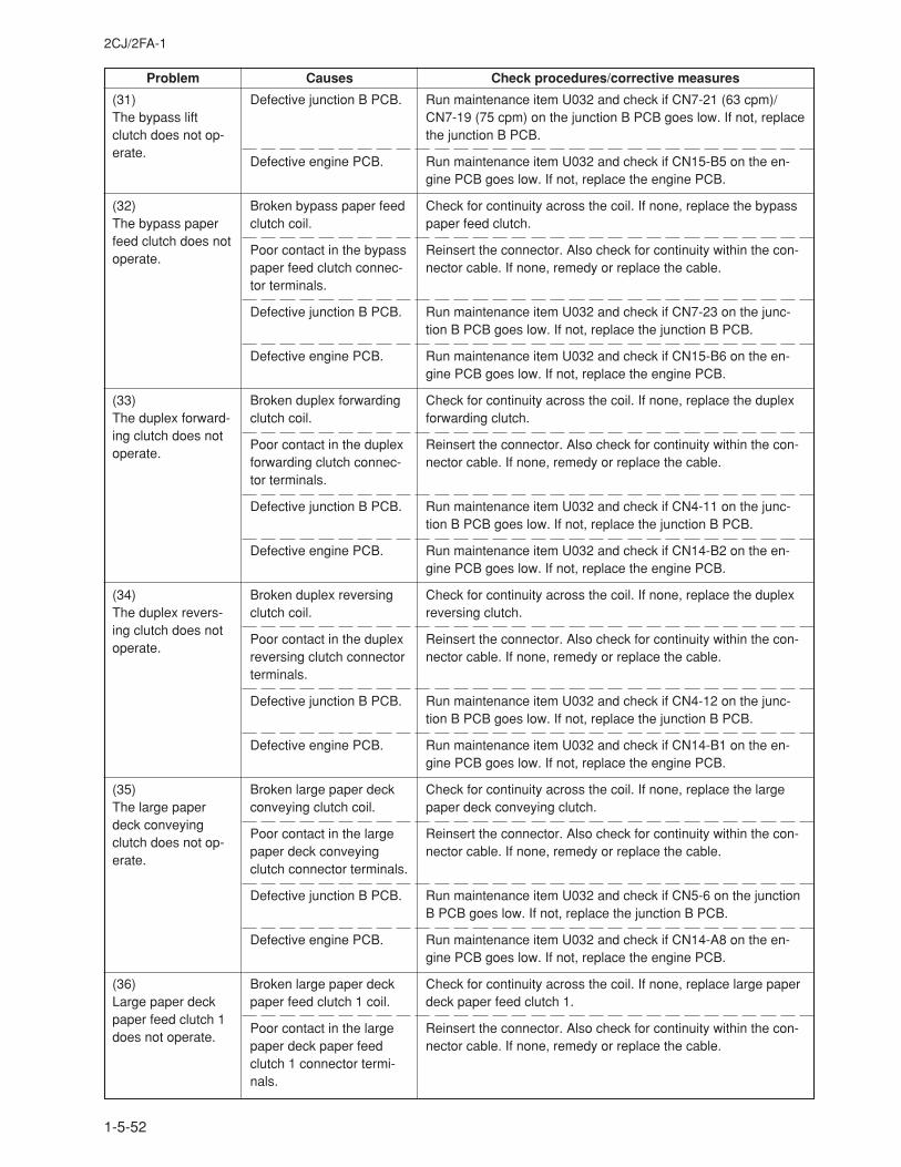
2CJ/2FA-1
1-5-52
Problem Causes Check procedures/corrective measures
Defective junction B PCB.
Defective engine PCB.
Broken bypass paper feedclutch coil.
Poor contact in the bypasspaper feed clutch connec-tor terminals.
Defective junction B PCB.
Defective engine PCB.
Broken duplex forwardingclutch coil.
Poor contact in the duplexforwarding clutch connec-tor terminals.
Defective junction B PCB.
Defective engine PCB.
Broken duplex reversingclutch coil.
Poor contact in the duplexreversing clutch connectorterminals.
Defective junction B PCB.
Defective engine PCB.
Broken large paper deckconveying clutch coil.
Poor contact in the largepaper deck conveyingclutch connector terminals.
Defective junction B PCB.
Defective engine PCB.
Broken large paper deckpaper feed clutch 1 coil.
Poor contact in the largepaper deck paper feedclutch 1 connector termi-nals.
Run maintenance item U032 and check if CN7-21 (63 cpm)/CN7-19 (75 cpm) on the junction B PCB goes low. If not, replacethe junction B PCB.
Run maintenance item U032 and check if CN15-B5 on the en-gine PCB goes low. If not, replace the engine PCB.
Check for continuity across the coil. If none, replace the bypasspaper feed clutch.
Reinsert the connector. Also check for continuity within the con-nector cable. If none, remedy or replace the cable.
Run maintenance item U032 and check if CN7-23 on the junc-tion B PCB goes low. If not, replace the junction B PCB.
Run maintenance item U032 and check if CN15-B6 on the en-gine PCB goes low. If not, replace the engine PCB.
Check for continuity across the coil. If none, replace the duplexforwarding clutch.
Reinsert the connector. Also check for continuity within the con-nector cable. If none, remedy or replace the cable.
Run maintenance item U032 and check if CN4-11 on the junc-tion B PCB goes low. If not, replace the junction B PCB.
Run maintenance item U032 and check if CN14-B2 on the en-gine PCB goes low. If not, replace the engine PCB.
Check for continuity across the coil. If none, replace the duplexreversing clutch.
Reinsert the connector. Also check for continuity within the con-nector cable. If none, remedy or replace the cable.
Run maintenance item U032 and check if CN4-12 on the junc-tion B PCB goes low. If not, replace the junction B PCB.
Run maintenance item U032 and check if CN14-B1 on the en-gine PCB goes low. If not, replace the engine PCB.
Check for continuity across the coil. If none, replace the largepaper deck conveying clutch.
Reinsert the connector. Also check for continuity within the con-nector cable. If none, remedy or replace the cable.
Run maintenance item U032 and check if CN5-6 on the junctionB PCB goes low. If not, replace the junction B PCB.
Run maintenance item U032 and check if CN14-A8 on the en-gine PCB goes low. If not, replace the engine PCB.
Check for continuity across the coil. If none, replace large paperdeck paper feed clutch 1.
Reinsert the connector. Also check for continuity within the con-nector cable. If none, remedy or replace the cable.
(31)The bypass liftclutch does not op-erate.
(32)The bypass paperfeed clutch does notoperate.
(33)The duplex forward-ing clutch does notoperate.
(34)The duplex revers-ing clutch does notoperate.
(35)The large paperdeck conveyingclutch does not op-erate.
(36)Large paper deckpaper feed clutch 1does not operate.
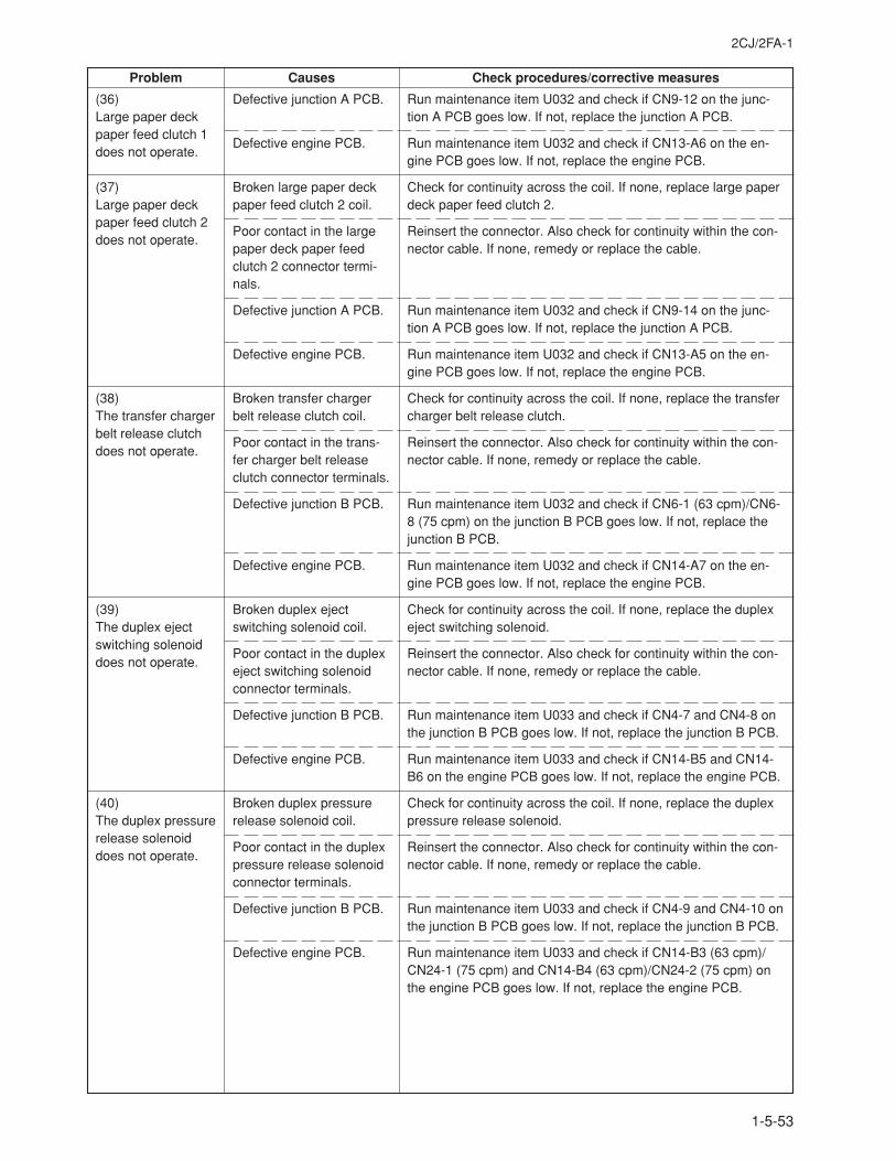
2CJ/2FA-1
1-5-53
Problem Causes Check procedures/corrective measures
Defective junction A PCB.
Defective engine PCB.
Broken large paper deckpaper feed clutch 2 coil.
Poor contact in the largepaper deck paper feedclutch 2 connector termi-nals.
Defective junction A PCB.
Defective engine PCB.
Broken transfer chargerbelt release clutch coil.
Poor contact in the trans-fer charger belt releaseclutch connector terminals.
Defective junction B PCB.
Defective engine PCB.
Broken duplex ejectswitching solenoid coil.
Poor contact in the duplexeject switching solenoidconnector terminals.
Defective junction B PCB.
Defective engine PCB.
Broken duplex pressurerelease solenoid coil.
Poor contact in the duplexpressure release solenoidconnector terminals.
Defective junction B PCB.
Defective engine PCB.
Run maintenance item U032 and check if CN9-12 on the junc-tion A PCB goes low. If not, replace the junction A PCB.
Run maintenance item U032 and check if CN13-A6 on the en-gine PCB goes low. If not, replace the engine PCB.
Check for continuity across the coil. If none, replace large paperdeck paper feed clutch 2.
Reinsert the connector. Also check for continuity within the con-nector cable. If none, remedy or replace the cable.
Run maintenance item U032 and check if CN9-14 on the junc-tion A PCB goes low. If not, replace the junction A PCB.
Run maintenance item U032 and check if CN13-A5 on the en-gine PCB goes low. If not, replace the engine PCB.
Check for continuity across the coil. If none, replace the transfercharger belt release clutch.
Reinsert the connector. Also check for continuity within the con-nector cable. If none, remedy or replace the cable.
Run maintenance item U032 and check if CN6-1 (63 cpm)/CN6-8 (75 cpm) on the junction B PCB goes low. If not, replace thejunction B PCB.
Run maintenance item U032 and check if CN14-A7 on the en-gine PCB goes low. If not, replace the engine PCB.
Check for continuity across the coil. If none, replace the duplexeject switching solenoid.
Reinsert the connector. Also check for continuity within the con-nector cable. If none, remedy or replace the cable.
Run maintenance item U033 and check if CN4-7 and CN4-8 onthe junction B PCB goes low. If not, replace the junction B PCB.
Run maintenance item U033 and check if CN14-B5 and CN14-B6 on the engine PCB goes low. If not, replace the engine PCB.
Check for continuity across the coil. If none, replace the duplexpressure release solenoid.
Reinsert the connector. Also check for continuity within the con-nector cable. If none, remedy or replace the cable.
Run maintenance item U033 and check if CN4-9 and CN4-10 onthe junction B PCB goes low. If not, replace the junction B PCB.
Run maintenance item U033 and check if CN14-B3 (63 cpm)/CN24-1 (75 cpm) and CN14-B4 (63 cpm)/CN24-2 (75 cpm) onthe engine PCB goes low. If not, replace the engine PCB.
(36)Large paper deckpaper feed clutch 1does not operate.
(37)Large paper deckpaper feed clutch 2does not operate.
(38)The transfer chargerbelt release clutchdoes not operate.
(39)The duplex ejectswitching solenoiddoes not operate.
(40)The duplex pressurerelease solenoiddoes not operate.
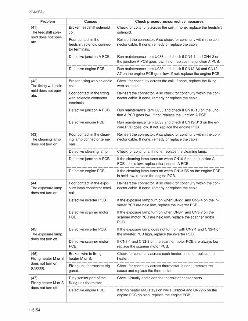
2CJ/2FA-1
1-5-54
Problem Causes Check procedures/corrective measures
Check for continuity across the coil. If none, replace the feedshiftsolenoid.
Reinsert the connector. Also check for continuity within the con-nector cable. If none, remedy or replace the cable.
Run maintenance item U033 and check if CN4-1 and CN4-2 onthe junction A PCB goes low. If not, replace the junction A PCB.
Run maintenance item U033 and check if CN12-A6 and CN12-A7 on the engine PCB goes low. If not, replace the engine PCB.
Check for continuity across the coil. If none, replace the fixingweb solenoid.
Reinsert the connector. Also check for continuity within the con-nector cable. If none, remedy or replace the cable.
Run maintenance item U033 and check if CN10-10 on the junc-tion A PCB goes low. If not, replace the junction A PCB.
Run maintenance item U033 and check if CN13-B13 on the en-gine PCB goes low. If not, replace the engine PCB.
Reinsert the connector. Also check for continuity within the con-nector cable. If none, remedy or replace the cable.
Check for continuity. If none, replace the cleaning lamp.
If the cleaning lamp turns on when CN10-8 on the junction APCB is held low, replace the junction A PCB.
If the cleaning lamp turns on when CN13-B5 on the engine PCBis held low, replace the engine PCB.
Reinsert the connector. Also check for continuity within the con-nector cable. If none, remedy or replace the cable.
If the exposure lamp turn on when CN2-1 and CN2-4 on the in-verter PCB are held low, replace the inverter PCB.
If the exposure lamp turn on when CN3-1 and CN3-2 on thescanner motor PCB are held low, replace the scanner motorPCB.
If the exposure lamp does not turn off with CN2-1 and CN2-4 onthe inverter PCB high, replace the inverter PCB.
If CN3-1 and CN3-2 on the scanner motor PCB are always low,replace the scanner motor PCB.
Check for continuity across each heater. If none, replace theheater.
Check for continuity across thermostat. If none, remove thecause and replace the thermostat.
Check visually and clean the thermistor sensor parts.
If fixing heater M/S stays on while CN22-4 and CN22-5 on theengine PCB go high, replace the engine PCB.
Broken feedshift solenoidcoil.
Poor contact in thefeedshift solenoid connec-tor terminals.
Defective junction A PCB.
Defective engine PCB.
Broken fixing web solenoidcoil.
Poor contact in the fixingweb solenoid connectorterminals.
Defective junction A PCB.
Defective engine PCB.
Poor contact in the clean-ing lamp connector termi-nals.
Defective cleaning lamp.
Defective junction A PCB.
Defective engine PCB.
Poor contact in the expo-sure lamp connector termi-nals.
Defective inverter PCB.
Defective scanner motorPCB.
Defective inverter PCB.
Defective scanner motorPCB.
Broken wire in fixingheater M or S.
Fixing unit thermostat trig-gered.
Dirty sensor part of thefixing unit thermistor.
Defective engine PCB.
(41)The feedshift sole-noid does not oper-ate.
(42)The fixing web sole-noid does not oper-ate.
(43)The cleaning lampdoes not turn on.
(44)The exposure lampdoes not turn on.
(45)The exposure lampdoes not turn off.
(46)Fixing heater M or Sdoes not turn on(C6000).
(47)Fixing heater M or Sdoes not turn off.
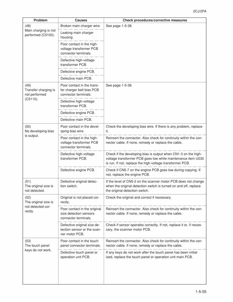
2CJ/2FA
1-5-55
Problem Causes Check procedures/corrective measures
See page 1-5-38.
See page 1-5-38.
Check the developing bias wire. If there is any problem, replaceit.
Reinsert the connector. Also check for continuity within the con-nector cable. If none, remedy or replace the cable.
Check if the developing bias is output when CN1-3 on the high-voltage transformer PCB goes low while maintenance item U030is run. If not, replace the high-voltage transformer PCB.
Check if CN5-7 on the engine PCB goes low during copying. Ifnot, replace the engine PCB.
If the level of CN5-2 on the scanner motor PCB does not changewhen the original detection switch is turned on and off, replacethe original detection switch.
Check the original and correct if necessary.
Reinsert the connector. Also check for continuity within the con-nector cable. If none, remedy or replace the cable.
Check if sensor operates correctly. If not, replace it or, if neces-sary, the scanner motor PCB.
Reinsert the connector. Also check for continuity within the con-nector cable. If none, remedy or replace the cable.
If any keys do not work after the touch panel has been initial-ized, replace the touch panel or operation unit main PCB.
Broken main charger wire.
Leaking main chargerhousing.
Poor contact in the high-voltage transformer PCBconnector terminals.
Defective high-voltagetransformer PCB.
Defective engine PCB.
Defective main PCB.
Poor contact in the trans-fer charger belt bias PCBconnector terminals.
Defective high-voltagetransformer PCB.
Defective engine PCB.
Defective main PCB.
Poor contact in the devel-oping bias wire.
Poor contact in the high-voltage transformer PCBconnector terminals.
Defective high-voltagetransformer PCB.
Defective engine PCB.
Defective original detec-tion switch.
Original is not placed cor-rectly.
Poor contact in the originalsize detection sensorsconnector terminals.
Defective original size de-tection sensor or the scan-ner motor PCB.
Poor contact in the touchpanel connector terminals.
Defective touch panel oroperation unit PCB.
(48)Main charging is notperformed (C5100).
(49)Transfer charging isnot performed(C5110).
(50)No developing biasis output.
(51)The original size isnot detected.
(52)The original size isnot detected cor-rectly.
(53)The touch panelkeys do not work.
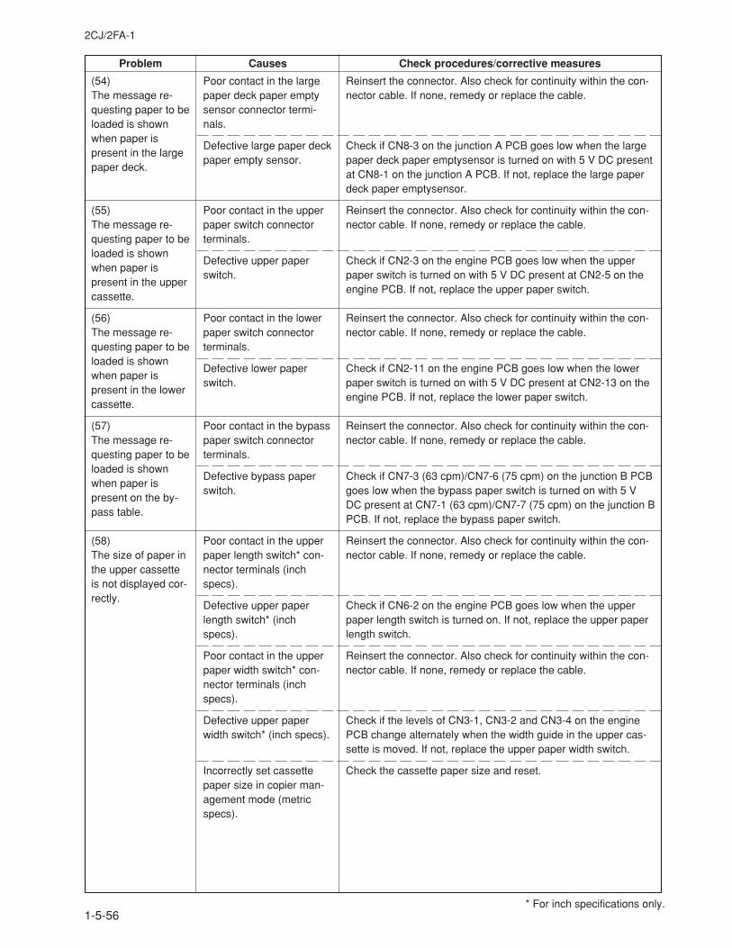
2CJ/2FA-1
1-5-56
Problem Causes Check procedures/corrective measures
Poor contact in the largepaper deck paper emptysensor connector termi-nals.
Defective large paper deckpaper empty sensor.
Poor contact in the upperpaper switch connectorterminals.
Defective upper paperswitch.
Poor contact in the lowerpaper switch connectorterminals.
Defective lower paperswitch.
Poor contact in the bypasspaper switch connectorterminals.
Defective bypass paperswitch.
Poor contact in the upperpaper length switch* con-nector terminals (inchspecs).
Defective upper paperlength switch* (inchspecs).
Poor contact in the upperpaper width switch* con-nector terminals (inchspecs).
Defective upper paperwidth switch* (inch specs).
Incorrectly set cassettepaper size in copier man-agement mode (metricspecs).
Reinsert the connector. Also check for continuity within the con-nector cable. If none, remedy or replace the cable.
Check if CN8-3 on the junction A PCB goes low when the largepaper deck paper emptysensor is turned on with 5 V DC presentat CN8-1 on the junction A PCB. If not, replace the large paperdeck paper emptysensor.
Reinsert the connector. Also check for continuity within the con-nector cable. If none, remedy or replace the cable.
Check if CN2-3 on the engine PCB goes low when the upperpaper switch is turned on with 5 V DC present at CN2-5 on theengine PCB. If not, replace the upper paper switch.
Reinsert the connector. Also check for continuity within the con-nector cable. If none, remedy or replace the cable.
Check if CN2-11 on the engine PCB goes low when the lowerpaper switch is turned on with 5 V DC present at CN2-13 on theengine PCB. If not, replace the lower paper switch.
Reinsert the connector. Also check for continuity within the con-nector cable. If none, remedy or replace the cable.
Check if CN7-3 (63 cpm)/CN7-6 (75 cpm) on the junction B PCBgoes low when the bypass paper switch is turned on with 5 VDC present at CN7-1 (63 cpm)/CN7-7 (75 cpm) on the junction BPCB. If not, replace the bypass paper switch.
Reinsert the connector. Also check for continuity within the con-nector cable. If none, remedy or replace the cable.
Check if CN6-2 on the engine PCB goes low when the upperpaper length switch is turned on. If not, replace the upper paperlength switch.
Reinsert the connector. Also check for continuity within the con-nector cable. If none, remedy or replace the cable.
Check if the levels of CN3-1, CN3-2 and CN3-4 on the enginePCB change alternately when the width guide in the upper cas-sette is moved. If not, replace the upper paper width switch.
Check the cassette paper size and reset.
(54)The message re-questing paper to beloaded is shownwhen paper ispresent in the largepaper deck.
(55)The message re-questing paper to beloaded is shownwhen paper ispresent in the uppercassette.
(56)The message re-questing paper to beloaded is shownwhen paper ispresent in the lowercassette.
(57)The message re-questing paper to beloaded is shownwhen paper ispresent on the by-pass table.
(58)The size of paper inthe upper cassetteis not displayed cor-rectly.
* For inch specifications only.
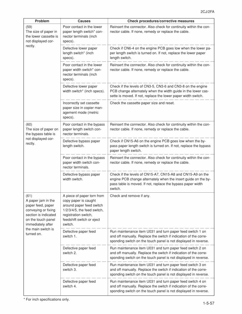
2CJ/2FA
1-5-57
Problem Causes Check procedures/corrective measures
Poor contact in the lowerpaper length switch* con-nector terminals (inchspecs).
Defective lower paperlength switch* (inchspecs).
Poor contact in the lowerpaper width switch* con-nector terminals (inchspecs).
Defective lower paperwidth switch* (inch specs).
Incorrectly set cassettepaper size in copier man-agement mode (metricspecs).
Poor contact in the bypasspaper length switch con-nector terminals.
Defective bypass paperlength switch.
Poor contact in the bypasspaper width switch con-nector terminals.
Defective bypass paperwidth switch.
A piece of paper torn fromcopy paper is caughtaround paper feed switch1/2/3/4/5, the feed switch,registration switch,feedshift switch or ejectswitch.
Defective paper feedswitch 1.
Defective paper feedswitch 2.
Defective paper feedswitch 3.
Defective paper feedswitch 4.
Reinsert the connector. Also check for continuity within the con-nector cable. If none, remedy or replace the cable.
Check if CN6-4 on the engine PCB goes low when the lower pa-per length switch is turned on. If not, replace the lower paperlength switch.
Reinsert the connector. Also check for continuity within the con-nector cable. If none, remedy or replace the cable.
Check if the levels of CN3-5, CN3-6 and CN3-8 on the enginePCB change alternately when the width guide in the lower cas-sette is moved. If not, replace the lower paper width switch.
Check the cassette paper size and reset.
Reinsert the connector. Also check for continuity within the con-nector cable. If none, remedy or replace the cable.
Check if CN15-A6 on the engine PCB goes low when the by-pass paper length switch is turned on. If not, replace the bypasspaper length switch.
Reinsert the connector. Also check for continuity within the con-nector cable. If none, remedy or replace the cable.
Check if the levels of CN15-A7, CN15-A8 and CN15-A9 on theengine PCB change alternately when the insert guide on the by-pass table is moved. If not, replace the bypass paper widthswitch.
Check and remove if any.
Run maintenance item U031 and turn paper feed switch 1 onand off manually. Replace the switch if indication of the corre-sponding switch on the touch panel is not displayed in reverse.
Run maintenance item U031 and turn paper feed switch 2 onand off manually. Replace the switch if indication of the corre-sponding switch on the touch panel is not displayed in reverse.
Run maintenance item U031 and turn paper feed switch 3 onand off manually. Replace the switch if indication of the corre-sponding switch on the touch panel is not displayed in reverse.
Run maintenance item U031 and turn paper feed switch 4 onand off manually. Replace the switch if indication of the corre-sponding switch on the touch panel is not displayed in reverse.
(59)The size of paper inthe lower cassette isnot displayed cor-rectly.
(60)The size of paper onthe bypass table isnot displayed cor-rectly.
(61)A paper jam in thepaper feed, paperconveying or fixingsection is indicatedon the touch panelimmediately afterthe main switch isturned on.
* For inch specifications only.
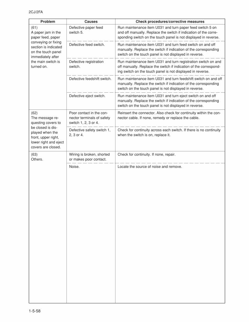
2CJ/2FA
1-5-58
Problem Causes Check procedures/corrective measures
Defective paper feedswitch 5.
Defective feed switch.
Defective registrationswitch.
Defective feedshift switch.
Defective eject switch.
Poor contact in the con-nector terminals of safetyswitch 1, 2, 3 or 4.
Defective safety switch 1,2, 3 or 4.
Wiring is broken, shortedor makes poor contact.
Noise.
Run maintenance item U031 and turn paper feed switch 5 onand off manually. Replace the switch if indication of the corre-sponding switch on the touch panel is not displayed in reverse.
Run maintenance item U031 and turn feed switch on and offmanually. Replace the switch if indication of the correspondingswitch on the touch panel is not displayed in reverse.
Run maintenance item U031 and turn registration switch on andoff manually. Replace the switch if indication of the correspond-ing switch on the touch panel is not displayed in reverse.
Run maintenance item U031 and turn feedshift switch on and offmanually. Replace the switch if indication of the correspondingswitch on the touch panel is not displayed in reverse.
Run maintenance item U031 and turn eject switch on and offmanually. Replace the switch if indication of the correspondingswitch on the touch panel is not displayed in reverse.
Reinsert the connector. Also check for continuity within the con-nector cable. If none, remedy or replace the cable.
Check for continuity across each switch. If there is no continuitywhen the switch is on, replace it.
Check for continuity. If none, repair.
Locate the source of noise and remove.
(61)A paper jam in thepaper feed, paperconveying or fixingsection is indicatedon the touch panelimmediately afterthe main switch isturned on.
(62)The message re-questing covers tobe closed is dis-played when thefront, upper right,lower right and ejectcovers are closed.
(63)Others.
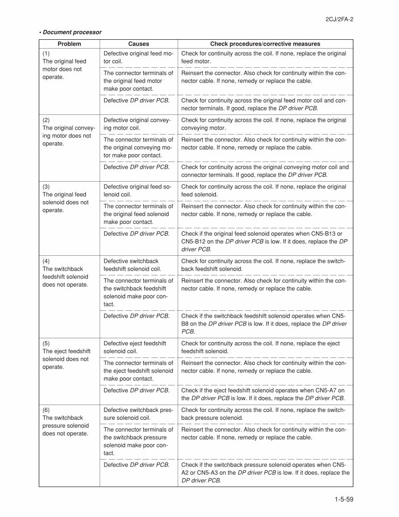
2CJ/2FA-2
1-5-59
• Document processor
Problem Causes Check procedures/corrective measures
(1)The original feedmotor does notoperate.
(2)The original convey-ing motor does notoperate.
(3)The original feedsolenoid does notoperate.
(4)The switchbackfeedshift solenoiddoes not operate.
(5)The eject feedshiftsolenoid does notoperate.
(6)The switchbackpressure solenoiddoes not operate.
Defective original feed mo-tor coil.
The connector terminals ofthe original feed motormake poor contact.
Defective DP driver PCB.
Defective original convey-ing motor coil.
The connector terminals ofthe original conveying mo-tor make poor contact.
Defective DP driver PCB.
Defective original feed so-lenoid coil.
The connector terminals ofthe original feed solenoidmake poor contact.
Defective DP driver PCB.
Defective switchbackfeedshift solenoid coil.
The connector terminals ofthe switchback feedshiftsolenoid make poor con-tact.
Defective DP driver PCB.
Defective eject feedshiftsolenoid coil.
The connector terminals ofthe eject feedshift solenoidmake poor contact.
Defective DP driver PCB.
Defective switchback pres-sure solenoid coil.
The connector terminals ofthe switchback pressuresolenoid make poor con-tact.
Defective DP driver PCB.
Check for continuity across the coil. If none, replace the originalfeed motor.
Reinsert the connector. Also check for continuity within the con-nector cable. If none, remedy or replace the cable.
Check for continuity across the original feed motor coil and con-nector terminals. If good, replace the DP driver PCB.
Check for continuity across the coil. If none, replace the originalconveying motor.
Reinsert the connector. Also check for continuity within the con-nector cable. If none, remedy or replace the cable.
Check for continuity across the original conveying motor coil andconnector terminals. If good, replace the DP driver PCB.
Check for continuity across the coil. If none, replace the originalfeed solenoid.
Reinsert the connector. Also check for continuity within the con-nector cable. If none, remedy or replace the cable.
Check if the original feed solenoid operates when CN5-B13 orCN5-B12 on the DP driver PCB is low. If it does, replace the DPdriver PCB.
Check for continuity across the coil. If none, replace the switch-back feedshift solenoid.
Reinsert the connector. Also check for continuity within the con-nector cable. If none, remedy or replace the cable.
Check if the switchback feedshift solenoid operates when CN5-B8 on the DP driver PCB is low. If it does, replace the DP driverPCB.
Check for continuity across the coil. If none, replace the ejectfeedshift solenoid.
Reinsert the connector. Also check for continuity within the con-nector cable. If none, remedy or replace the cable.
Check if the eject feedshift solenoid operates when CN5-A7 onthe DP driver PCB is low. If it does, replace the DP driver PCB.
Check for continuity across the coil. If none, replace the switch-back pressure solenoid.
Reinsert the connector. Also check for continuity within the con-nector cable. If none, remedy or replace the cable.
Check if the switchback pressure solenoid operates when CN5-A2 or CN5-A3 on the DP driver PCB is low. If it does, replace theDP driver PCB.
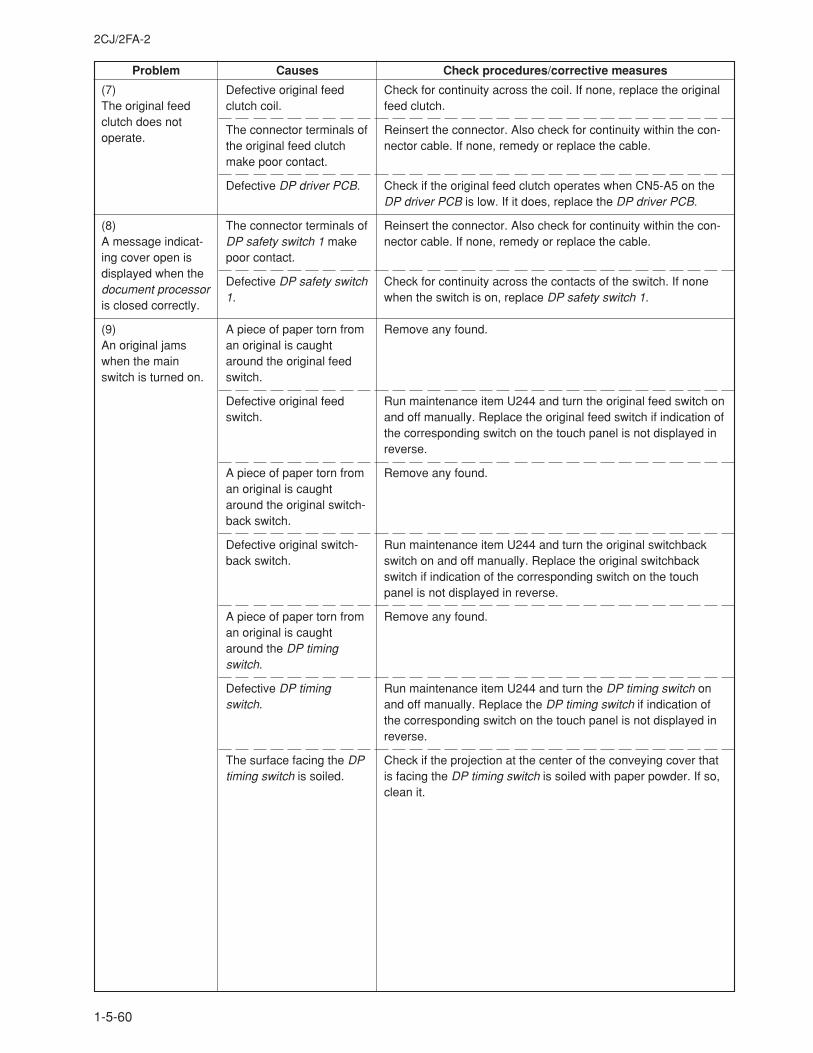
2CJ/2FA-2
1-5-60
Problem Causes Check procedures/corrective measures
Defective original feedclutch coil.
The connector terminals ofthe original feed clutchmake poor contact.
Defective DP driver PCB.
The connector terminals ofDP safety switch 1 makepoor contact.
Defective DP safety switch1.
A piece of paper torn froman original is caughtaround the original feedswitch.
Defective original feedswitch.
A piece of paper torn froman original is caughtaround the original switch-back switch.
Defective original switch-back switch.
A piece of paper torn froman original is caughtaround the DP timingswitch.
Defective DP timingswitch.
The surface facing the DPtiming switch is soiled.
(7)The original feedclutch does notoperate.
(8)A message indicat-ing cover open isdisplayed when thedocument processoris closed correctly.
(9)An original jamswhen the mainswitch is turned on.
Check for continuity across the coil. If none, replace the originalfeed clutch.
Reinsert the connector. Also check for continuity within the con-nector cable. If none, remedy or replace the cable.
Check if the original feed clutch operates when CN5-A5 on theDP driver PCB is low. If it does, replace the DP driver PCB.
Reinsert the connector. Also check for continuity within the con-nector cable. If none, remedy or replace the cable.
Check for continuity across the contacts of the switch. If nonewhen the switch is on, replace DP safety switch 1.
Remove any found.
Run maintenance item U244 and turn the original feed switch onand off manually. Replace the original feed switch if indication ofthe corresponding switch on the touch panel is not displayed inreverse.
Remove any found.
Run maintenance item U244 and turn the original switchbackswitch on and off manually. Replace the original switchbackswitch if indication of the corresponding switch on the touchpanel is not displayed in reverse.
Remove any found.
Run maintenance item U244 and turn the DP timing switch onand off manually. Replace the DP timing switch if indication ofthe corresponding switch on the touch panel is not displayed inreverse.
Check if the projection at the center of the conveying cover thatis facing the DP timing switch is soiled with paper powder. If so,clean it.
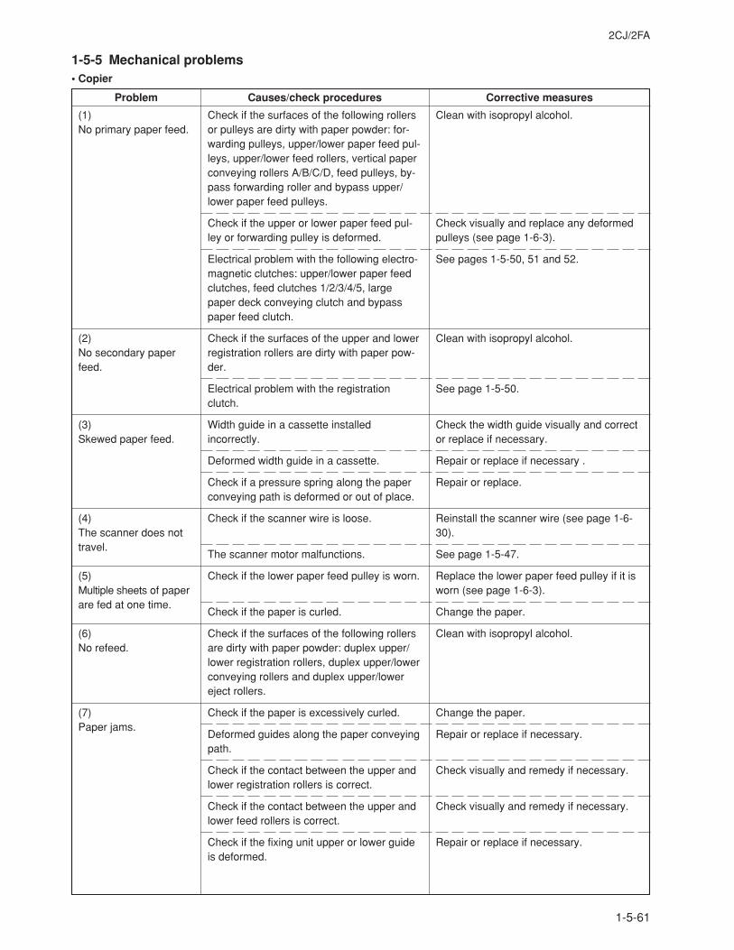
2CJ/2FA
1-5-61
Clean with isopropyl alcohol.
Check visually and replace any deformedpulleys (see page 1-6-3).
See pages 1-5-50, 51 and 52.
Clean with isopropyl alcohol.
See page 1-5-50.
Check the width guide visually and corrector replace if necessary.
Repair or replace if necessary .
Repair or replace.
Reinstall the scanner wire (see page 1-6-30).
See page 1-5-47.
Replace the lower paper feed pulley if it isworn (see page 1-6-3).
Change the paper.
Clean with isopropyl alcohol.
Change the paper.
Repair or replace if necessary.
Check visually and remedy if necessary.
Check visually and remedy if necessary.
Repair or replace if necessary.
(1)No primary paper feed.
(2)No secondary paperfeed.
(3)Skewed paper feed.
(4)The scanner does nottravel.
(5)Multiple sheets of paperare fed at one time.
(6)No refeed.
(7)Paper jams.
Check if the surfaces of the following rollersor pulleys are dirty with paper powder: for-warding pulleys, upper/lower paper feed pul-leys, upper/lower feed rollers, vertical paperconveying rollers A/B/C/D, feed pulleys, by-pass forwarding roller and bypass upper/lower paper feed pulleys.
Check if the upper or lower paper feed pul-ley or forwarding pulley is deformed.
Electrical problem with the following electro-magnetic clutches: upper/lower paper feedclutches, feed clutches 1/2/3/4/5, largepaper deck conveying clutch and bypasspaper feed clutch.
Check if the surfaces of the upper and lowerregistration rollers are dirty with paper pow-der.
Electrical problem with the registrationclutch.
Width guide in a cassette installedincorrectly.
Deformed width guide in a cassette.
Check if a pressure spring along the paperconveying path is deformed or out of place.
Check if the scanner wire is loose.
The scanner motor malfunctions.
Check if the lower paper feed pulley is worn.
Check if the paper is curled.
Check if the surfaces of the following rollersare dirty with paper powder: duplex upper/lower registration rollers, duplex upper/lowerconveying rollers and duplex upper/lowereject rollers.
Check if the paper is excessively curled.
Deformed guides along the paper conveyingpath.
Check if the contact between the upper andlower registration rollers is correct.
Check if the contact between the upper andlower feed rollers is correct.
Check if the fixing unit upper or lower guideis deformed.
Problem Causes/check procedures Corrective measures
1-5-5 Mechanical problems• Copier
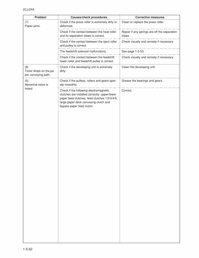
2CJ/2FA
1-5-62
Problem Causes/check procedures Corrective measures
(7)Paper jams.
(8)Toner drops on the pa-per conveying path.
(9)Abnormal noise isheard.
Check if the press roller is extremely dirty ordeformed.
Check if the contact between the heat rollerand its separation claws is correct.
Check if the contact between the eject rollerand pulley is correct.
The feedshift solenoid malfunctions.
Check if the contact between the feedshiftlower roller and feedshift pulley is correct.
Check if the developing unit is extremelydirty.
Check if the pulleys, rollers and gears oper-ate smoothly.
Check if the following electromagneticclutches are installed correctly: upper/lowerpaper feed clutches, feed clutches 1/2/3/4/5,large paper deck conveying clutch andbypass paper feed clutch.
Clean or replace the press roller.
Repair if any springs are off the separationclaws.
Check visually and remedy if necessary.
See page 1-5-53.
Check visually and remedy if necessary.
Clean the developing unit.
Grease the bearings and gears.
Correct.
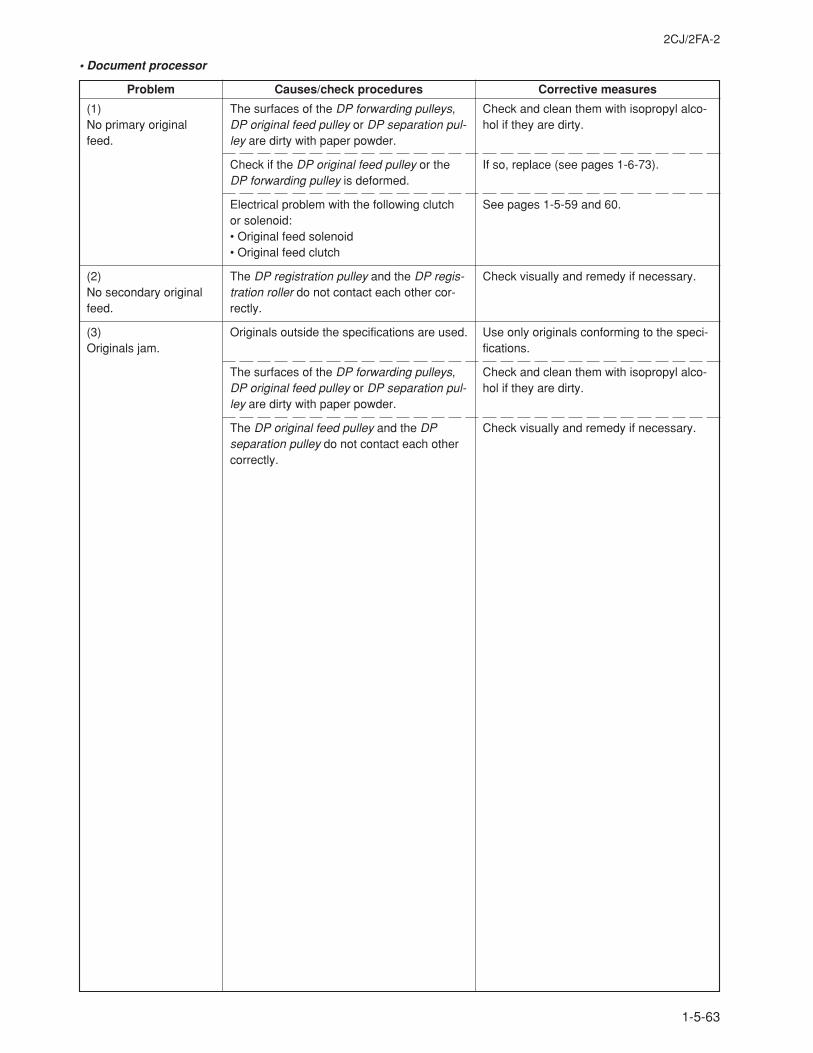
2CJ/2FA-2
1-5-63
(1)No primary originalfeed.
(2)No secondary originalfeed.
(3)Originals jam.
Check and clean them with isopropyl alco-hol if they are dirty.
If so, replace (see pages 1-6-73).
See pages 1-5-59 and 60.
Check visually and remedy if necessary.
Use only originals conforming to the speci-fications.
Check and clean them with isopropyl alco-hol if they are dirty.
Check visually and remedy if necessary.
• Document processor
Problem Causes/check procedures Corrective measures
The surfaces of the DP forwarding pulleys,DP original feed pulley or DP separation pul-ley are dirty with paper powder.
Check if the DP original feed pulley or theDP forwarding pulley is deformed.
Electrical problem with the following clutchor solenoid:• Original feed solenoid• Original feed clutch
The DP registration pulley and the DP regis-tration roller do not contact each other cor-rectly.
Originals outside the specifications are used.
The surfaces of the DP forwarding pulleys,DP original feed pulley or DP separation pul-ley are dirty with paper powder.
The DP original feed pulley and the DPseparation pulley do not contact each othercorrectly.
2CJ/2FA
1-6-1
1-6-1 Precautions for assembly and disassembly
(1) Precautions• Be sure to turn the main switch off and disconnect the power plug before starting disassembly.• When handling PCBs, do not touch connectors with bare hands or damage the board.• Do not touch any PCB containing ICs with bare hands or any object prone to static charge.• Use only the specified parts to replace the fixing unit thermostat. Never substitute electric wires, as the copier may be
seriously damaged.• Use the following testers when measuring voltages:
Hioki 3200Sanwa MD-180CSanwa YX-360TRBeckman TECH300Beckman DM45Beckman 330*Beckman 3030*Beckman DM850*Fluke 8060A*Arlec DMM1050Arlec YF1030C* Capable of measuring RMS values.
• Prepare the following as test originals:1. NTC (new test chart)2. NPTC (newspaper test chart)
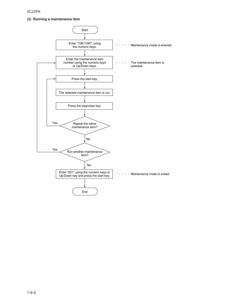
2CJ/2FA
1-6-2
(2) Running a maintenance item
Enter “10871087” using the numeric keys.
Enter “001” using the numeric keys or Up/Down key and press the start key.
Enter the maintenance item number using the numeric keys
or Up/Down keys.
The selected maintenance item is run.
Press the stop/clear key.
Press the start key.
Start
End
Maintenance mode is entered.
The maintenance item is selected.
Maintenance mode is exited.
Repeat the same maintenance item?
Run another maintenance item?
No
No
Yes
Yes
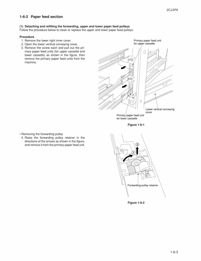
2CJ/2FA
1-6-3
1-6-2 Paper feed section
(1) Detaching and refitting the forwarding, upper and lower paper feed pulleysFollow the procedure below to clean or replace the upper and lower paper feed pulleys.
Procedure1. Remove the lower right inner cover.2. Open the lower vertical conveying cover.3. Remove the screw each and pull out the pri-
mary paper feed units (for upper cassette andlower cassette) as shown in the figure, thenremove the primary paper feed units from themachine.
Figure 1-6-1
• Removing the forwarding pulley4. Raise the forwarding pulley retainer in the
directions of the arrows as shown in the figure,and remove it from the primary paper feed unit.
Figure 1-6-2
Primary paper feed unit for lower cassette
Lower vertical conveying cover
Primary paper feed unit for upper cassette
Forwarding pulley retainer
1
2
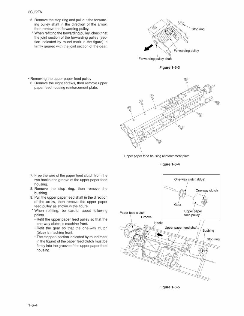
2CJ/2FA
1-6-4
5. Remove the stop ring and pull out the forward-ing pulley shaft in the direction of the arrow,then remove the forwarding pulley.
* When refitting the forwarding pulley, check thatthe joint section of the forwarding pulley (sec-tion indicated by round mark in the figure) isfirmly geared with the joint section of the gear.
Figure 1-6-3
• Removing the upper paper feed pulley6. Remove the eight screws, then remove upper
paper feed housing reinforcement plate.
Figure 1-6-4
7. Free the wire of the paper feed clutch from thetwo hooks and groove of the upper paper feedhousing.
8. Remove the stop ring, then remove thebushing.
9. Pull the upper paper feed shaft in the directionof the arrow, then remove the upper paperfeed pulley as shown in the figure.
* When refitting, be careful about followingpoints.• Refit the upper paper feed pulley so that the
one-way clutch is machine front.• Refit the gear so that the one-way clutch
(blue) is machine front.• The stopper (section indicated by round mark
in the figure) of the paper feed clutch must befirmly into the groove of the upper paper feedhousing.
Figure 1-6-5
Forwarding pulley shaft
Forwarding pulley
Stop ring
Upper paper feed housing reinforcement plate
Paper feed clutch
BushingUpper paper feed shaft
Groove
Stop ring
Hooks
One-way clutch (blue)
Upper paper feed pulley
One-way clutch
Gear
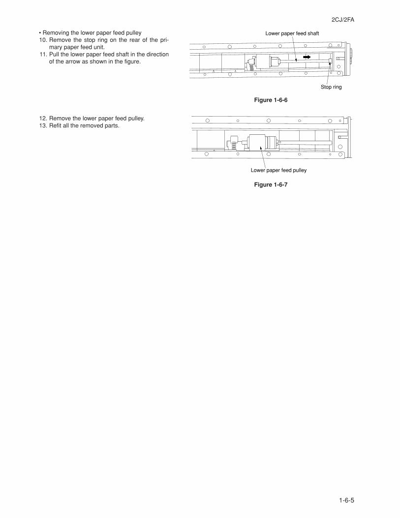
2CJ/2FA
1-6-5
• Removing the lower paper feed pulley10. Remove the stop ring on the rear of the pri-
mary paper feed unit.11. Pull the lower paper feed shaft in the direction
of the arrow as shown in the figure.
Figure 1-6-6
12. Remove the lower paper feed pulley.13. Refit all the removed parts.
Figure 1-6-7
Lower paper feed shaft
Stop ring
Lower paper feed pulley
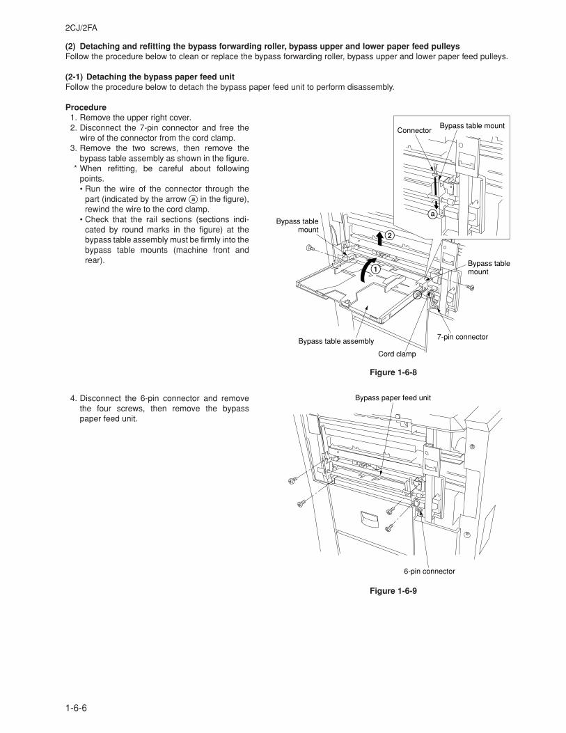
2CJ/2FA
1-6-6
(2) Detaching and refitting the bypass forwarding roller, bypass upper and lower paper feed pulleysFollow the procedure below to clean or replace the bypass forwarding roller, bypass upper and lower paper feed pulleys.
(2-1) Detaching the bypass paper feed unitFollow the procedure below to detach the bypass paper feed unit to perform disassembly.
Procedure1. Remove the upper right cover.2. Disconnect the 7-pin connector and free the
wire of the connector from the cord clamp.3. Remove the two screws, then remove the
bypass table assembly as shown in the figure.* When refitting, be careful about following
points.• Run the wire of the connector through the
part (indicated by the arrow a in the figure),rewind the wire to the cord clamp.
• Check that the rail sections (sections indi-cated by round marks in the figure) at thebypass table assembly must be firmly into thebypass table mounts (machine front andrear).
Figure 1-6-8
4. Disconnect the 6-pin connector and removethe four screws, then remove the bypasspaper feed unit.
Figure 1-6-9
Bypass table assembly
Cord clamp
7-pin connector
Bypass table mount
Bypass table mount
Bypass table mountConnector
1
2
a
Bypass paper feed unit
6-pin connector
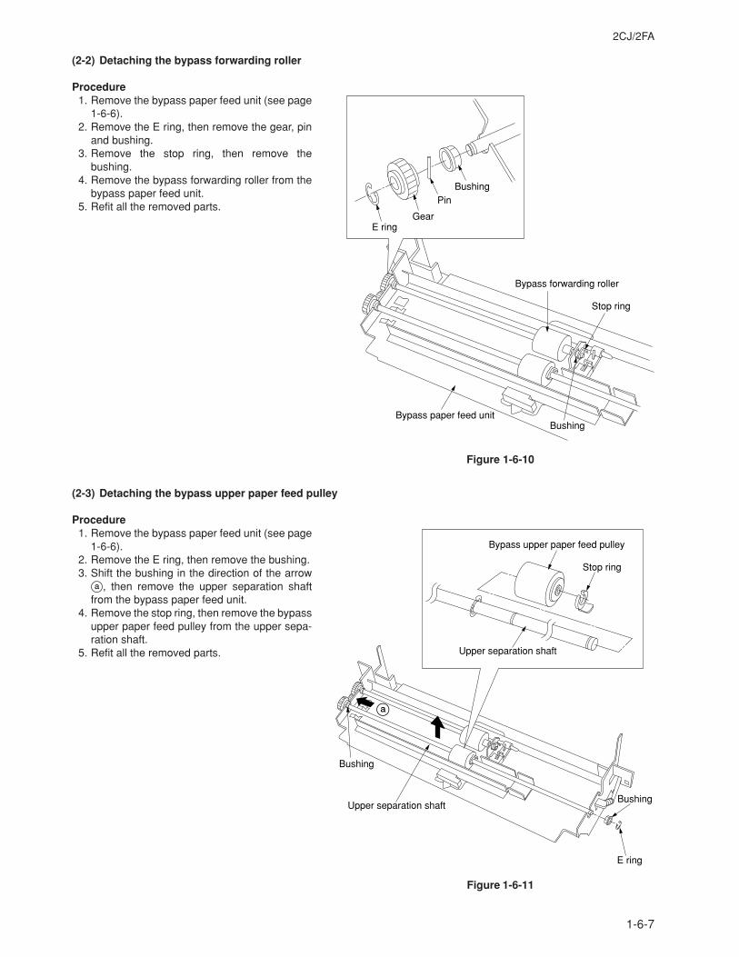
2CJ/2FA
1-6-7
(2-2) Detaching the bypass forwarding roller
Procedure1. Remove the bypass paper feed unit (see page
1-6-6).2. Remove the E ring, then remove the gear, pin
and bushing.3. Remove the stop ring, then remove the
bushing.4. Remove the bypass forwarding roller from the
bypass paper feed unit.5. Refit all the removed parts.
Figure 1-6-10
(2-3) Detaching the bypass upper paper feed pulley
Procedure1. Remove the bypass paper feed unit (see page
1-6-6).2. Remove the E ring, then remove the bushing.3. Shift the bushing in the direction of the arrow
a, then remove the upper separation shaftfrom the bypass paper feed unit.
4. Remove the stop ring, then remove the bypassupper paper feed pulley from the upper sepa-ration shaft.
5. Refit all the removed parts.
Figure 1-6-11
Bypass forwarding roller
Stop ring
BushingBypass paper feed unit
Bushing
Gear
Pin
E ring
Bushing
Bushing
E ring
Upper separation shaft
Bypass upper paper feed pulley
Stop ring
Upper separation shaft
a
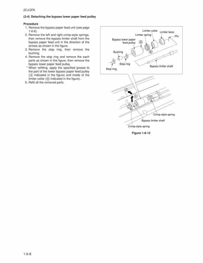
2CJ/2FA
1-6-8
(2-4) Detaching the bypass lower paper feed pulley
Procedure1. Remove the bypass paper feed unit (see page
1-6-6).2. Remove the left and right crimp-style springs,
then remove the bypass limiter shaft from thebypass paper feed unit in the direction of thearrows as shown in the figure.
3. Remove the stop ring, then remove thebushing.
4. Remove the stop ring and remove the eachparts as shown in the figure, then remove thebypass lower paper feed pulley.
* When refitting, apply the specified grease tothe part of the lower bypass paper feed pulley(a indicated in the figure) and inside of thelimiter collar (b indicated in the figure).
5. Refit all the removed parts.
Figure 1-6-12
Stop ring
Crimp-style spring
Crimp-style spring
Stop ring
Bushing
Bypass lower paper feed pulley
Bypass limiter shaft
Bypass limiter shaft
Limiter springLimiter boss
Pin
Limiter collar
b
1
a
2
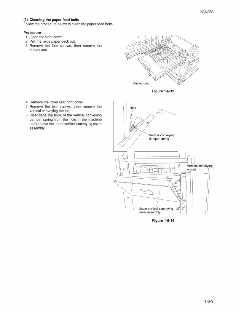
2CJ/2FA
1-6-9
(3) Cleaning the paper feed beltsFollow the procedure below to clean the paper feed belts.
Procedure1. Open the front cover.2. Pull the large paper deck out.3. Remove the four screws, then remove the
duplex unit.
Figure 1-6-13
4. Remove the lower rear right cover.5. Remove the two screws, then remove the
vertical conveying mount.6. Disengage the hook of the vertical conveying
damper spring from the hole in the machineand remove the upper vertical conveying coverassembly.
Figure 1-6-14
Upper vertical conveying cover assembly
Vertical conveyingmount
Hole
Vertical conveying damper spring
Duplex unit
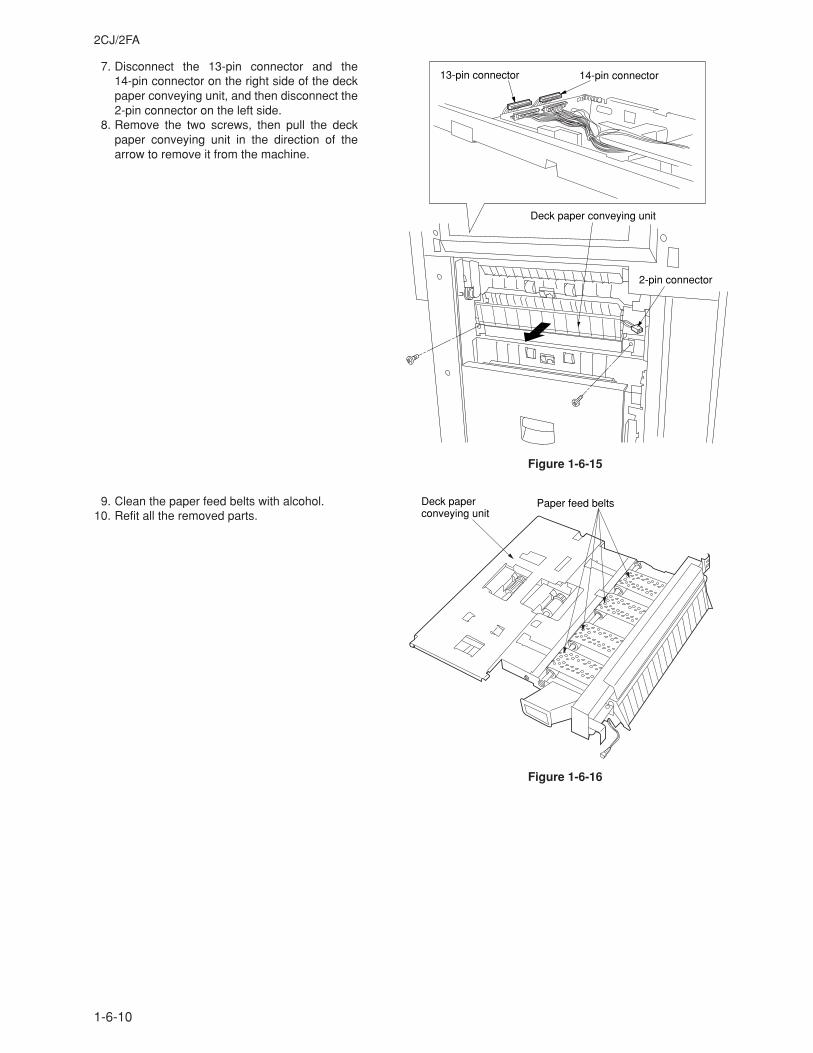
2CJ/2FA
1-6-10
7. Disconnect the 13-pin connector and the14-pin connector on the right side of the deckpaper conveying unit, and then disconnect the2-pin connector on the left side.
8. Remove the two screws, then pull the deckpaper conveying unit in the direction of thearrow to remove it from the machine.
Figure 1-6-15
9. Clean the paper feed belts with alcohol.10. Refit all the removed parts.
Figure 1-6-16
Deck paper conveying unit
2-pin connector
13-pin connector 14-pin connector
Deck paper conveying unit
Paper feed belts
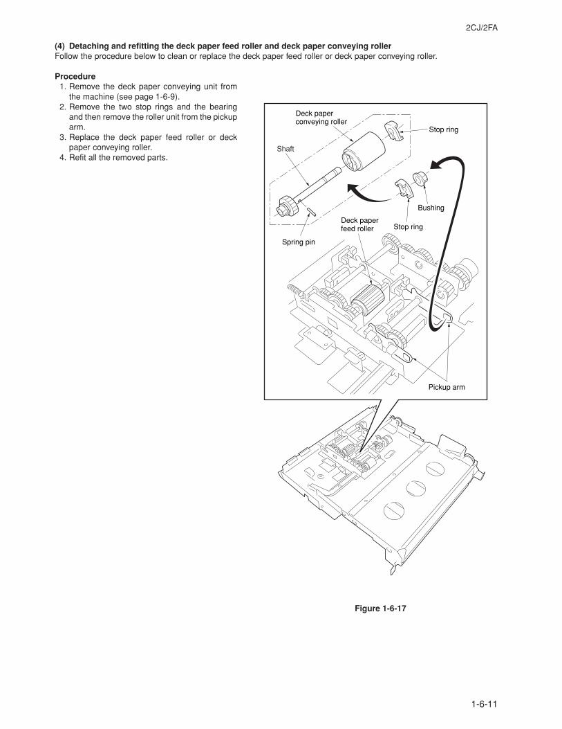
2CJ/2FA
1-6-11
(4) Detaching and refitting the deck paper feed roller and deck paper conveying rollerFollow the procedure below to clean or replace the deck paper feed roller or deck paper conveying roller.
Procedure1. Remove the deck paper conveying unit from
the machine (see page 1-6-9).2. Remove the two stop rings and the bearing
and then remove the roller unit from the pickuparm.
3. Replace the deck paper feed roller or deckpaper conveying roller.
4. Refit all the removed parts.
Figure 1-6-17
Deck paper conveying roller
Stop ring
Stop ring
Pickup arm
Spring pin
Deck paper feed roller
Bushing
Shaft
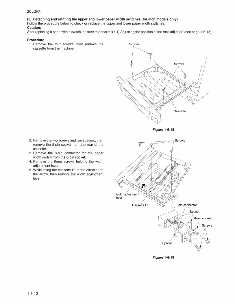
2CJ/2FA
1-6-12
(5) Detaching and refitting the upper and lower paper width switches (for inch models only)Follow the procedure below to check or replace the upper and lower paper width switches.Caution:After replacing a paper width switch, be sure to perform “(7-1) Adjusting the position of the rack adjuster” (see page 1-6-15).
Procedure1. Remove the four screws, then remove the
cassette from the machine.
Figure 1-6-18
2. Remove the two screws and two spacers, thenremove the 8-pin socket from the rear of thecassette.
3. Remove the 8-pin connector for the paperwidth switch from the 8-pin socket.
4. Remove the three screws holding the widthadjustment lever.
5. While lifting the cassette lift in the direction ofthe arrow, then remove the width adjustmentlever.
Figure 1-6-19
Screws
Cassette
Screws
Spacer
Spacer
Cassette lift
Width adjustment lever
Screws
8-pin socket
8-pin connector
Screws
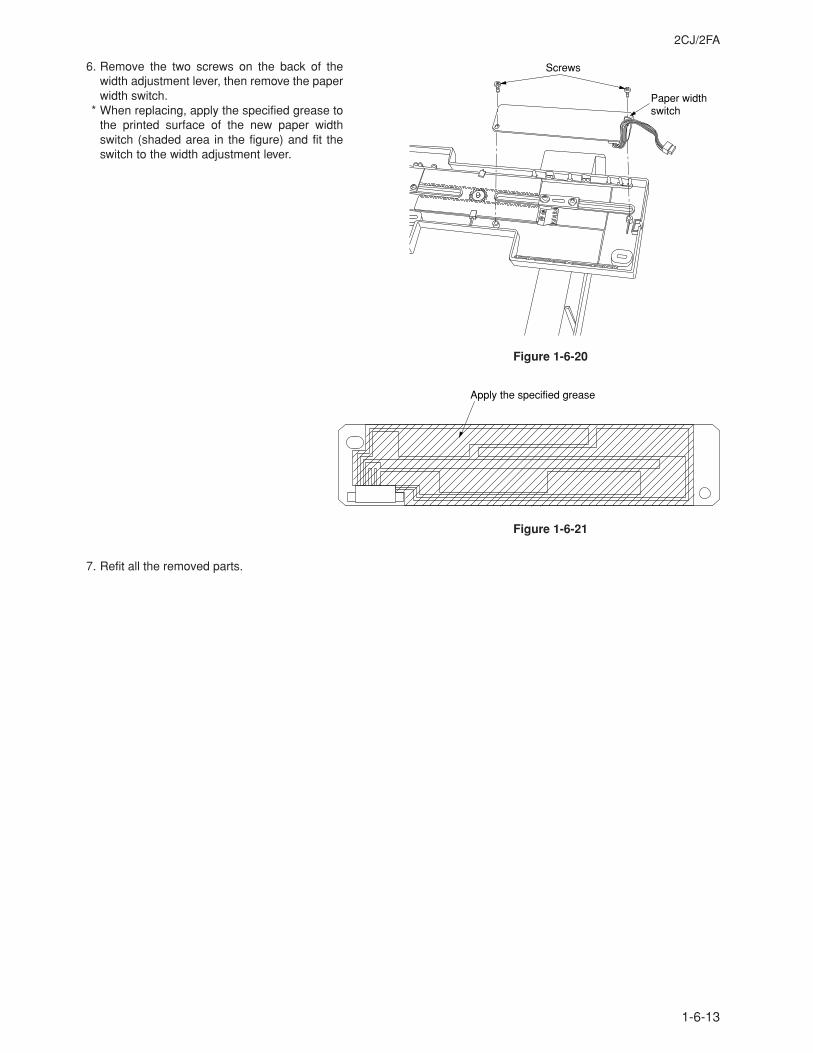
2CJ/2FA
1-6-13
6. Remove the two screws on the back of thewidth adjustment lever, then remove the paperwidth switch.
* When replacing, apply the specified grease tothe printed surface of the new paper widthswitch (shaded area in the figure) and fit theswitch to the width adjustment lever.
Figure 1-6-20
Figure 1-6-21
7. Refit all the removed parts.
Screws
Paper width switch
Apply the specified grease
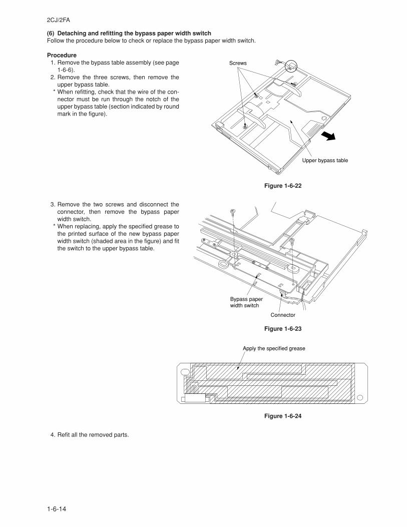
2CJ/2FA
1-6-14
(6) Detaching and refitting the bypass paper width switchFollow the procedure below to check or replace the bypass paper width switch.
Procedure1. Remove the bypass table assembly (see page
1-6-6).2. Remove the three screws, then remove the
upper bypass table.* When refitting, check that the wire of the con-
nector must be run through the notch of theupper bypass table (section indicated by roundmark in the figure).
Figure 1-6-22
3. Remove the two screws and disconnect theconnector, then remove the bypass paperwidth switch.
* When replacing, apply the specified grease tothe printed surface of the new bypass paperwidth switch (shaded area in the figure) and fitthe switch to the upper bypass table.
Figure 1-6-23
Figure 1-6-24
4. Refit all the removed parts.
Screws
Upper bypass table
Bypass paper width switch
Connector
Apply the specified grease
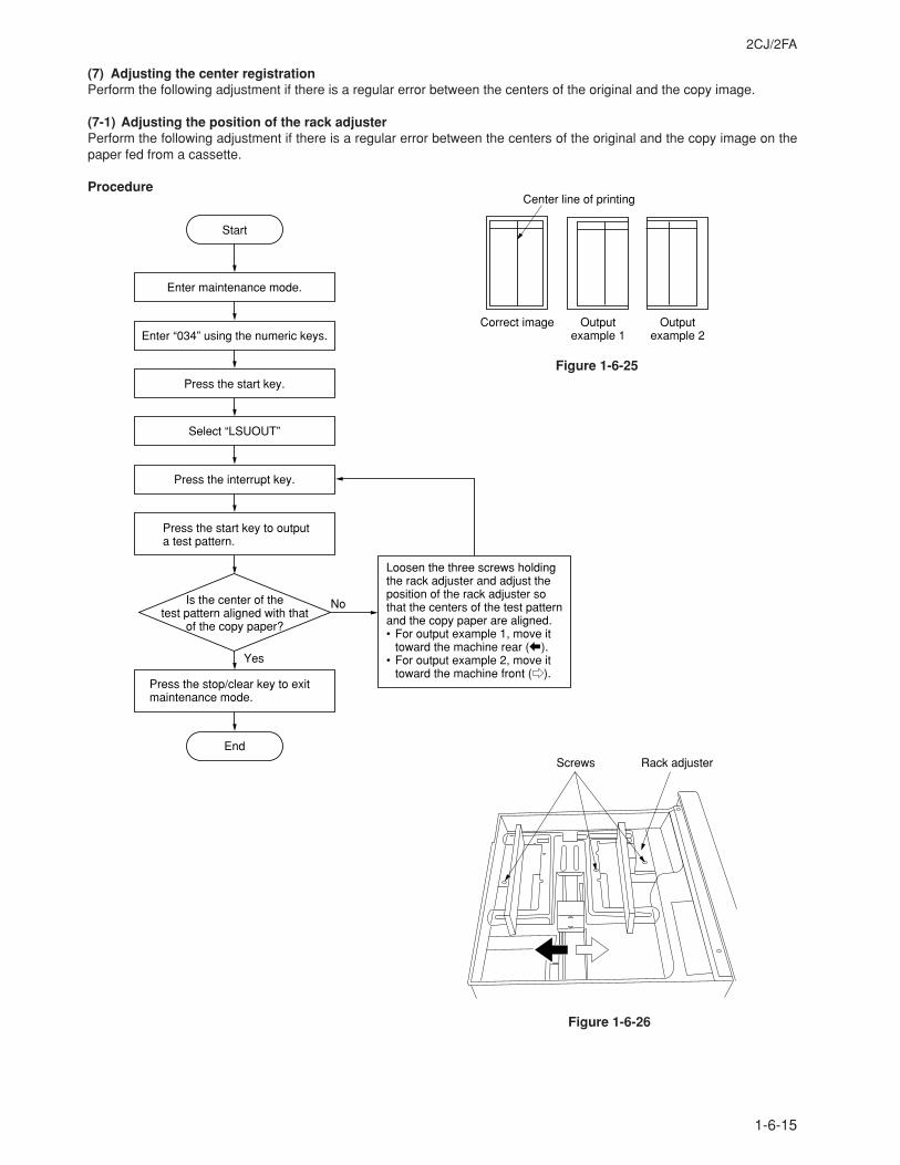
2CJ/2FA
1-6-15
(7) Adjusting the center registrationPerform the following adjustment if there is a regular error between the centers of the original and the copy image.
(7-1) Adjusting the position of the rack adjusterPerform the following adjustment if there is a regular error between the centers of the original and the copy image on thepaper fed from a cassette.
ProcedureCenter line of printing
Correct image Output example 1
Output example 2
Figure 1-6-25
Screws Rack adjuster
Figure 1-6-26
Start
Is the center of the test pattern aligned with that
of the copy paper?
Loosen the three screws holding the rack adjuster and adjust the position of the rack adjuster so that the centers of the test pattern and the copy paper are aligned.• For output example 1, move it
toward the machine rear (b).• For output example 2, move it
toward the machine front (e).
No
Yes
Enter maintenance mode.
Enter “034” using the numeric keys.
Press the start key.
Press the interrupt key.
Press the start key to output a test pattern.
Select “LSUOUT”
Press the stop/clear key to exit maintenance mode.
End
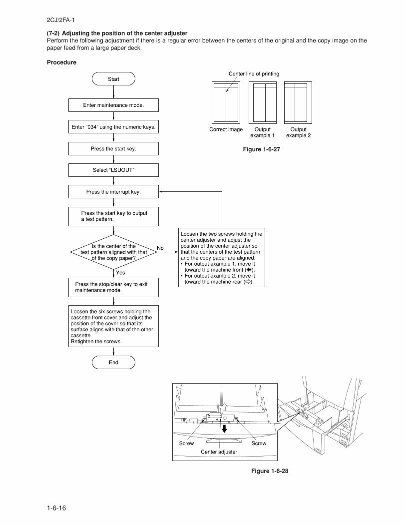
2CJ/2FA-1
1-6-16
(7-2) Adjusting the position of the center adjusterPerform the following adjustment if there is a regular error between the centers of the original and the copy image on thepaper feed from a large paper deck.
Procedure
Center line of printing
Correct image Output example 1
Output example 2
Figure 1-6-27
Screw Screw
Center adjuster
Figure 1-6-28
Loosen the six screws holding the cassette front cover and adjust the position of the cover so that its surface aligns with that of the other cassette.Retighten the screws.
Start
Is the center of the test pattern aligned with that
of the copy paper?
Loosen the two screws holding the center adjuster and adjust the position of the center adjuster so that the centers of the test pattern and the copy paper are aligned.• For output example 1, move it
toward the machine front (b).• For output example 2, move it
toward the machine rear (e).
No
Yes
Enter maintenance mode.
Enter “034” using the numeric keys.
Press the start key.
Press the interrupt key.
Press the start key to output a test pattern.
Press the stop/clear key to exit maintenance mode.
End
Select “LSUOUT”
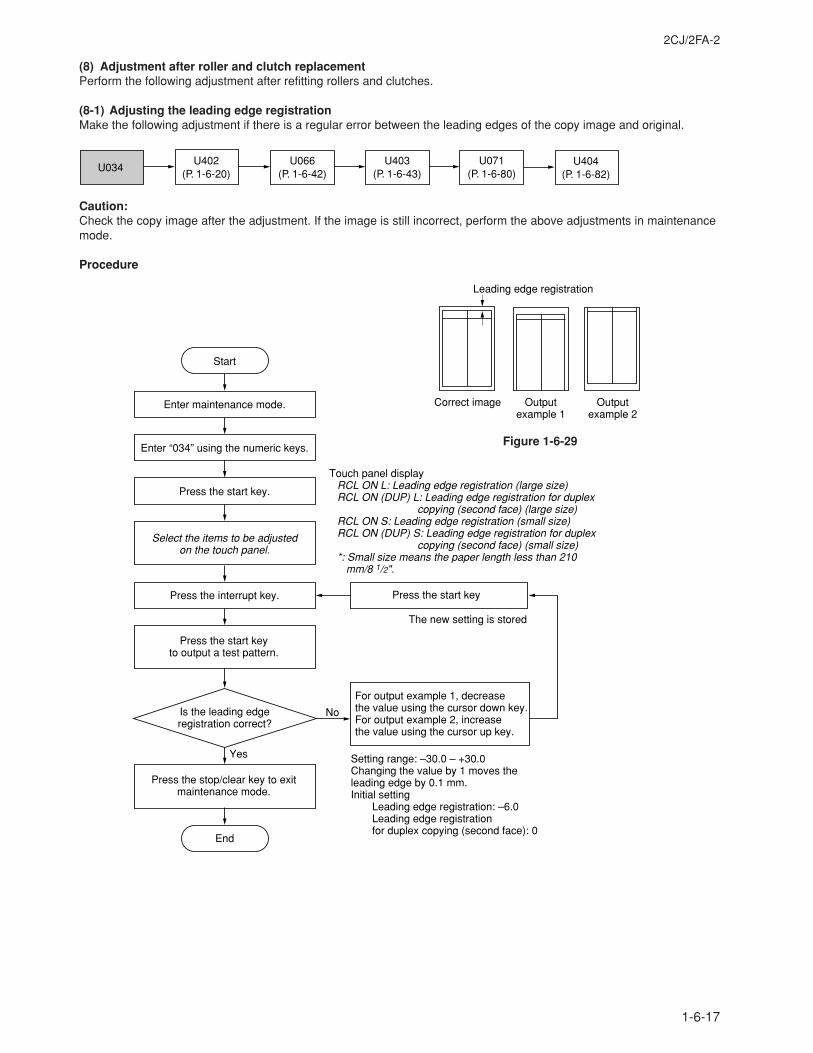
2CJ/2FA-2
1-6-17
(8) Adjustment after roller and clutch replacementPerform the following adjustment after refitting rollers and clutches.
(8-1) Adjusting the leading edge registrationMake the following adjustment if there is a regular error between the leading edges of the copy image and original.
U034U404
(P. 1-6-82)U066
(P. 1-6-42)U071
(P. 1-6-80)U403
(P. 1-6-43)U402
(P. 1-6-20)
Caution:Check the copy image after the adjustment. If the image is still incorrect, perform the above adjustments in maintenancemode.
Procedure
Yes
No
Start
Enter maintenance mode.
Enter “034” using the numeric keys.
Press the start key.
Press the interrupt key.
Is the leading edge registration correct?
Press the start key
The new setting is stored
Press the stop/clear key to exit maintenance mode.
End
Select the items to be adjusted on the touch panel.
For output example 1, decrease the value using the cursor down key.For output example 2, increase the value using the cursor up key.
Touch panel displayRCL ON L: Leading edge registration (large size)RCL ON (DUP) L: Leading edge registration for duplex
copying (second face) (large size)RCL ON S: Leading edge registration (small size)RCL ON (DUP) S: Leading edge registration for duplex
copying (second face) (small size)*: Small size means the paper length less than 210 mm/8 1/2".
Setting range: –30.0 – +30.0Changing the value by 1 moves the leading edge by 0.1 mm.Initial setting
Leading edge registration: –6.0Leading edge registration for duplex copying (second face): 0
Press the start key to output a test pattern.
Correct image Output example 1
Output example 2
Leading edge registration
Figure 1-6-29
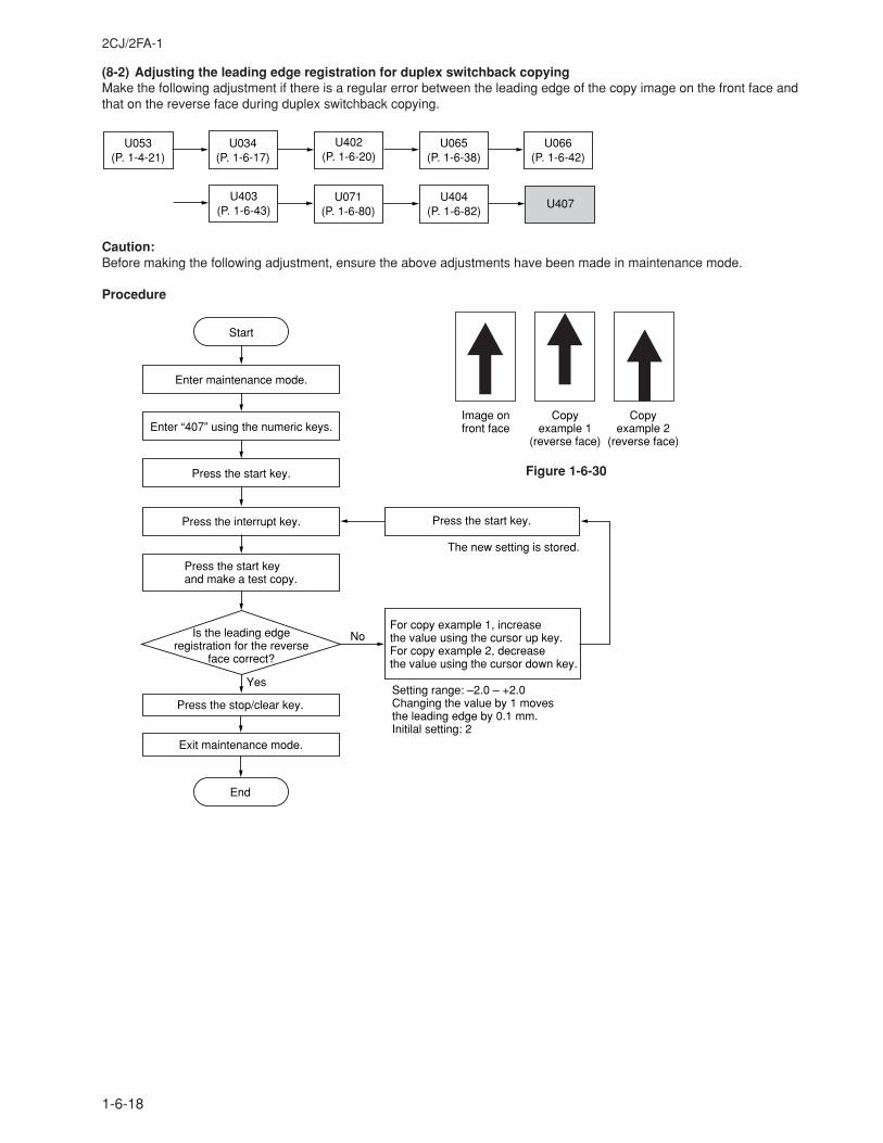
2CJ/2FA-1
1-6-18
(8-2) Adjusting the leading edge registration for duplex switchback copyingMake the following adjustment if there is a regular error between the leading edge of the copy image on the front face andthat on the reverse face during duplex switchback copying.
U053(P. 1-4-21)
U071(P. 1-6-80)
U404(P. 1-6-82)
U403(P. 1-6-43)
U065(P. 1-6-38)
U066(P. 1-6-42)
U407
U034(P. 1-6-17)
U402(P. 1-6-20)
Caution:Before making the following adjustment, ensure the above adjustments have been made in maintenance mode.
Procedure
Yes
No
Start
Enter maintenance mode.
Enter “407” using the numeric keys.
Press the start key.
Press the interrupt key.
Press the start key and make a test copy.
Is the leading edge registration for the reverse
face correct?
Press the start key.
The new setting is stored.
For copy example 1, increase the value using the cursor up key.For copy example 2, decrease the value using the cursor down key.
Setting range: –2.0 – +2.0Changing the value by 1 moves the leading edge by 0.1 mm.Initilal setting: 2
Press the stop/clear key.
Exit maintenance mode.
End
Image on front face
Copy example 1
(reverse face)
Copyexample 2
(reverse face)
Figure 1-6-30
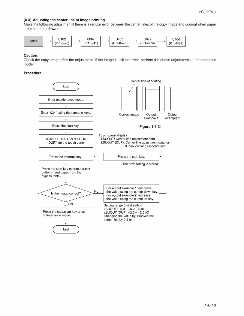
2CJ/2FA-1
1-6-19
(8-3) Adjusting the center line of image printingMake the following adjustment if there is a regular error between the center lines of the copy image and original when paperis fed from the drawer.
U034U404
(P. 1-6-82)U067
(P. 1-6-41)U072
(P. 1-6-79)U403
(P. 1-6-43)U402
(P. 1-6-20)
Caution:Check the copy image after the adjustment. If the image is still incorrect, perform the above adjustments in maintenancemode.
Procedure
Yes
No
Start
Enter maintenance mode.
Enter “034” using the numeric keys.
Press the start key.
Press the interrupt key.
Press the start key to output a test pattern (feed paper from the bypass table).
Is the image correct?
Press the start key.
The new setting is stored.
Press the stop/clear key to exit maintenance mode.
End
Select “LSUOUT” or “LSUOUT(DUP)” on the touch panel.
For output example 1, decrease the value using the cursor down key.For output example 2, increase the value using the cursor up key.
Setting range (initial setting)LSUOUT: –5.0 – +5.0 (–2.8)LSUOUT (DUP): –2.0 – +2.0 (0) Changing the value by 1 moves the center line by 0.1 mm.
Touch panel displayLSUOUT: Center line adjustment dataLSUOUT (DUP): Center line adjustment data for duplex copying (second face)
Center line of printing
Correct image Output example 1
Output example 2
Figure 1-6-31
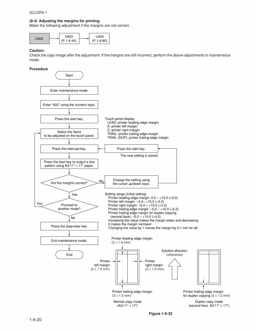
2CJ/2FA-1
1-6-20
(8-4) Adjusting the margins for printingMake the following adjustment if the margins are not correct.
U402U404
(P. 1-6-82)U403
(P. 1-6-45)
Caution:Check the copy image after the adjustment. If the margins are still incorrect, perform the above adjustments in maintenancemode.
Procedure
Yes
No
Start
Enter maintenance mode.
Enter “402” using the numeric keys.
Press the start key.
Press the start key to output a test pattern using A3/11" × 17" paper.
Press the start key.
The new setting is stored.
Setting range (initial setting)Printer leading edge margin: 0.0 – +10.0 (+3.0)Printer left margin: –3.4– +10.0 (+3.2)Printer right margin: –5.0 – +10.0 (+3.2)Printer trailing edge margin: –5.0 – +10.0 (+5.2)Printer trailing edge margin for duplex copying
(second face): –5.0 – +10.0 (+4.2)Increasing the value makes the margin wider and decreasing it makes the margin narrower.Changing the value by 1 moves the margin by 0.1 mm for all.
Select the items to be adjusted on the touch panel.
Are the margins correct?Change the setting using the cursor up/down keys.
Press the interrupt key.
Yes
No
Press the stop/clear key.
Exit maintenance mode.
End
Proceed to another mode?
Touch panel displayLEAD: printer leading edge marginA: printer left marginC: printer right marginTRAIL: printer trailing edge marginTRAIL (DUP): printer trailing edge margin
Ejection direction(reference)
Printer trailing edge margin for duplex copying (3 ± 1.0 mm)
Printer leading edge margin(3 ± 1.0 mm)
Printer left margin
(3 ± 1.0 mm)
Printer right margin(3 ± 1.0 mm)
Printer trailing edge margin(3 ± 1.0 mm)
Duplex copy mode (second face, A3/11" × 17")
Normal copy mode (A3/11" × 17")
Figure 1-6-32
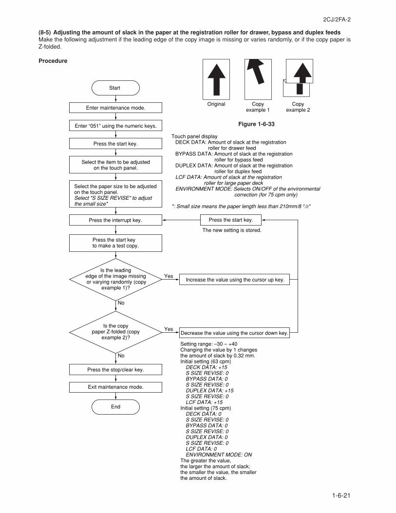
2CJ/2FA-2
1-6-21
(8-5) Adjusting the amount of slack in the paper at the registration roller for drawer, bypass and duplex feedsMake the following adjustment if the leading edge of the copy image is missing or varies randomly, or if the copy paper isZ-folded.
Procedure
End
Start
Enter maintenance mode.
Enter “051” using the numeric keys.
Yes
Yes
No
No
Press the start key.
Press the interrupt key.
Press the start key to make a test copy.
Press the stop/clear key.
Exit maintenance mode.
Decrease the value using the cursor down key.
Setting range: –30 – +40Changing the value by 1 changes the amount of slack by 0.32 mm.Initial setting (63 cpm)
DECK DATA: +15S SIZE REVISE: 0BYPASS DATA: 0S SIZE REVISE: 0DUPLEX DATA: +15S SIZE REVISE: 0LCF DATA: +15
Initial setting (75 cpm)DECK DATA: 0S SIZE REVISE: 0BYPASS DATA: 0S SIZE REVISE: 0DUPLEX DATA: 0S SIZE REVISE: 0LCF DATA: 0ENVIRONMENT MODE: ON
The greater the value, the larger the amount of slack; the smaller the value, the smaller the amount of slack.
The new setting is stored.
Select the item to be adjusted on the touch panel.
Select the paper size to be adjusted on the touch panel.Select "S SIZE REVISE" to adjust the small size*
Touch panel displayDECK DATA: Amount of slack at the registration
roller for drawer feedBYPASS DATA: Amount of slack at the registration
roller for bypass feedDUPLEX DATA: Amount of slack at the registration
roller for duplex feedLCF DATA: Amount of slack at the registration
roller for large paper deckENVIRONMENT MODE: Selects ON/OFF of the environmental
correction (for 75 cpm only)
*: Small size means the paper length less than 210mm/8 1/2"
Is the leading edge of the image missing or varying randomly (copy
example 1)?
Is the copy paper Z-folded (copy
example 2)?
Increase the value using the cursor up key.
Press the start key.
Original Copyexample 1
Copyexample 2
Figure 1-6-33
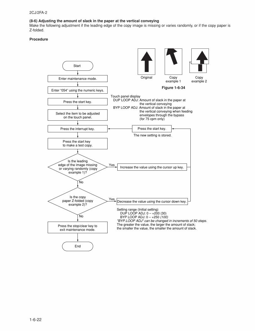
2CJ/2FA-2
1-6-22
(8-6) Adjusting the amount of slack in the paper at the vertical conveyingMake the following adjustment if the leading edge of the copy image is missing or varies randomly, or if the copy paper isZ-folded.
Procedure
Figure 1-6-34
End
Start
Enter maintenance mode.
Enter “054” using the numeric keys.
Yes
Yes
No
No
Press the start key.
Press the interrupt key.
Press the start key to make a test copy.
Decrease the value using the cursor down key.
Setting range (Initial setting)DUP LOOP ADJ: 0 – +200 (30)BYP LOOP ADJ: 0 – +250 (100)
"BYP.LOOP ADJ" can be changed in increments of 50 steps.The greater the value, the larger the amount of slack; the smaller the value, the smaller the amount of slack.
The new setting is stored.
Is the leading edge of the image missing or varying randomly (copy
example 1)?
Is the copy paper Z-folded (copy
example 2)?
Increase the value using the cursor up key.
Press the start key.
Press the stop/clear key to exit maintenance mode.
Select the item to be adjusted on the touch panel.
Touch panel displayDUP LOOP ADJ: Amount of slack in the paper at
the vertical conveyingBYP LOOP ADJ: Amount of slack in the paper at
the vertical conveying when feeding envelopes through the bypass (for 75 cpm only)
Original Copyexample 1
Copyexample 2
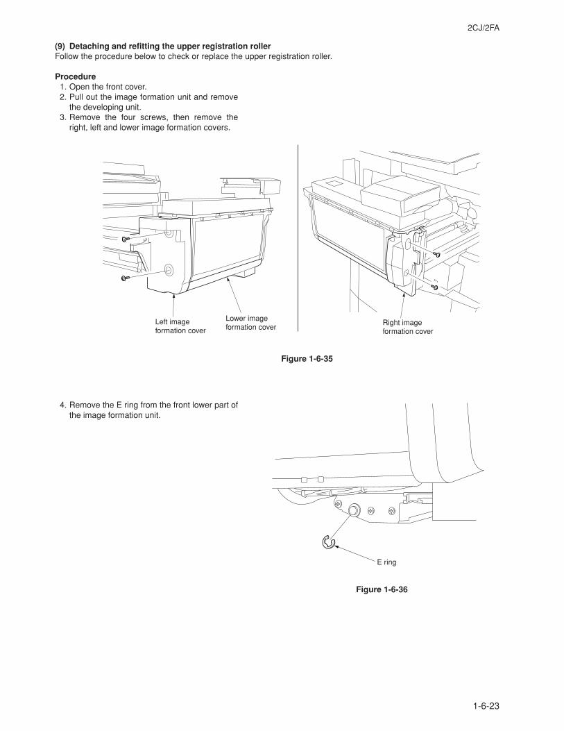
2CJ/2FA
1-6-23
(9) Detaching and refitting the upper registration rollerFollow the procedure below to check or replace the upper registration roller.
Procedure1. Open the front cover.2. Pull out the image formation unit and remove
the developing unit.3. Remove the four screws, then remove the
right, left and lower image formation covers.
Figure 1-6-35
4. Remove the E ring from the front lower part ofthe image formation unit.
Figure 1-6-36
Left image formation cover
Right image formation cover
Lower image formation cover
E ring
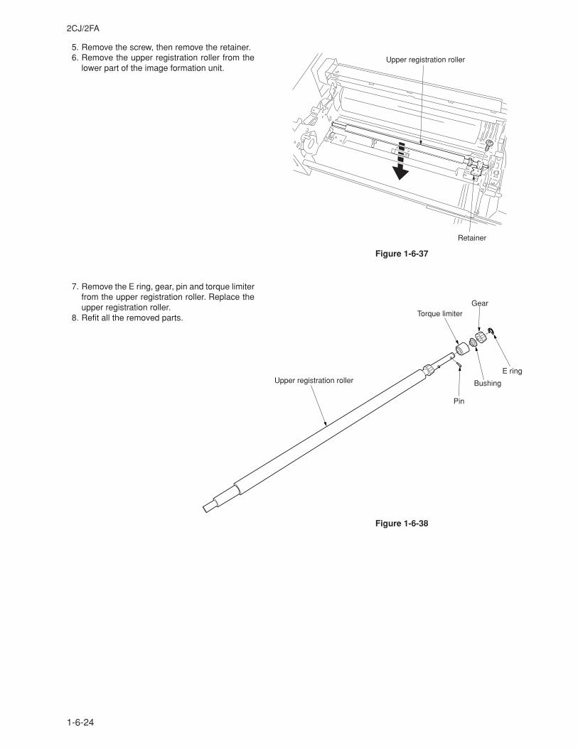
2CJ/2FA
1-6-24
5. Remove the screw, then remove the retainer.6. Remove the upper registration roller from the
lower part of the image formation unit.
7. Remove the E ring, gear, pin and torque limiterfrom the upper registration roller. Replace theupper registration roller.
8. Refit all the removed parts.
Figure 1-6-37
Figure 1-6-38
Upper registration roller
Retainer
Upper registration roller
Pin
E ring
Bushing
GearTorque limiter
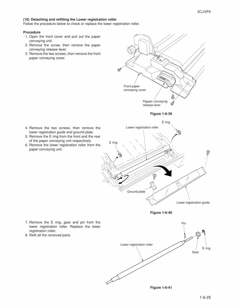
2CJ/2FA
1-6-25
(10) Detaching and refitting the Lower registration rollerFollow the procedure below to check or replace the lower registration roller.
Procedure1. Open the front cover and pull out the paper
conveying unit.2. Remove the screw, then remove the paper
conveying release lever.3. Remove the two screws, then remove the front
paper conveying cover.
Figure 1-6-39
4. Remove the two screws, then remove thelower registration guide and ground plate.
5. Remove the E ring from the front and the rearof the paper conveying unit respectively.
6. Remove the lower registration roller from thepaper conveying unit.
Figure 1-6-40
7. Remove the E ring, gear and pin from thelower registration roller. Replace the lowerregistration roller.
8. Refit all the removed parts.
Figure 1-6-41
Front paper conveying cover
Papaer conveying release lever
E ring
Lower registration roller
E ring
Ground plate
Lower registration guide
Lower registration roller
Pin
GearE ring
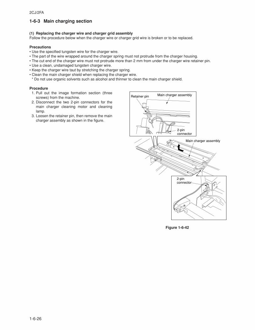
2CJ/2FA
1-6-26
1-6-3 Main charging section
(1) Replacing the charger wire and charger grid assemblyFollow the procedure below when the charger wire or charger grid wire is broken or to be replaced.
Precautions• Use the specified tungsten wire for the charger wire.• The part of the wire wrapped around the charger spring must not protrude from the charger housing.• The cut end of the charger wire must not protrude more than 2 mm from under the charger wire retainer pin.• Use a clean, undamaged tungsten charger wire.• Keep the charger wire taut by stretching the charger spring.• Clean the main charger shield when replacing the charger wire.
* Do not use organic solvents such as alcohol and thinner to clean the main charger shield.
Procedure1. Pull out the image formation section (three
screws) from the machine.2. Disconnect the two 2-pin connectors for the
main charger cleaning motor and cleaninglamp.
3. Loosen the retainer pin, then remove the maincharger assembly as shown in the figure.
Figure 1-6-42
Main charger assembly
Retainer pin
2-pin connector
Main charger assembly
2-pin connector
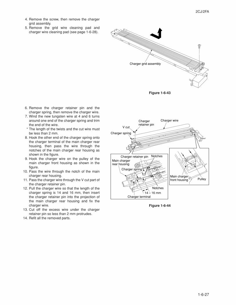
2CJ/2FA
1-6-27
4. Remove the screw, then remove the chargergrid assembly.
5. Remove the grid wire cleaning pad andcharger wire cleaning pad (see page 1-6-28).
Figure 1-6-43
6. Remove the charger retainer pin and thecharger spring, then remove the charger wire.
7. Wind the new tungsten wire at 4 and 6 turnsaround one end of the charger spring and trimthe end of the wire.
* The length of the twists and the cut wire mustbe less than 2 mm.
8. Hook the other end of the charger spring ontothe charger terminal of the main charger rearhousing, then pass the wire through thenotches of the main charger rear housing asshown in the figure.
9. Hook the charger wire on the pulley of themain charger front housing as shown in thefigure.
10. Pass the wire through the notch of the maincharger rear housing.
11. Pass the charger wire through the V cut part ofthe charger retainer pin.
12. Pull the charger wire so that the length of thecharger spring is 14 and 16 mm, then insertthe charger retainer pin into the projection ofthe main charger rear housing and fix thecharger wire.
13. Cut off the excess wire under the chargerretainer pin so less than 2 mm protrudes.
14. Refit all the removed parts.
Charger grid assembly
Charger spring
V cut
Charger retainer pin
Charger wire
Main charger rear housing
Charger retainer pin
Charger terminal14 – 16 mm
Notches
Notches
Charger spring
Main charger front housing Pulley
Figure 1-6-44
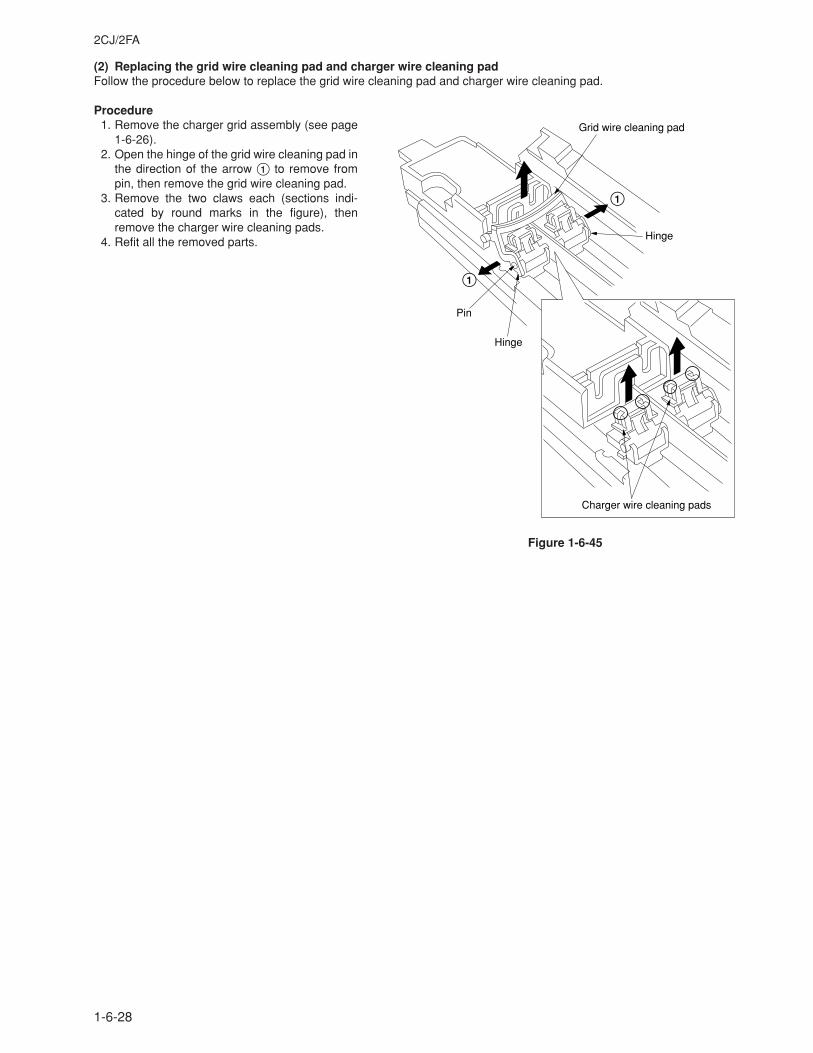
2CJ/2FA
1-6-28
(2) Replacing the grid wire cleaning pad and charger wire cleaning padFollow the procedure below to replace the grid wire cleaning pad and charger wire cleaning pad.
Procedure1. Remove the charger grid assembly (see page
1-6-26).2. Open the hinge of the grid wire cleaning pad in
the direction of the arrow 1 to remove frompin, then remove the grid wire cleaning pad.
3. Remove the two claws each (sections indi-cated by round marks in the figure), thenremove the charger wire cleaning pads.
4. Refit all the removed parts.
Figure 1-6-45
Grid wire cleaning pad
Pin
Hinge
Hinge
Charger wire cleaning pads
1
1
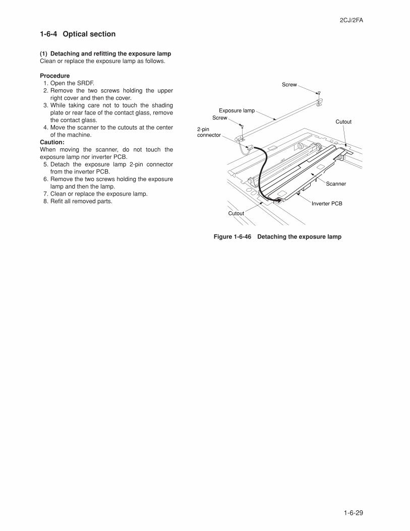
2CJ/2FA
1-6-29
1-6-4 Optical section
(1) Detaching and refitting the exposure lampClean or replace the exposure lamp as follows.
Procedure1. Open the SRDF.2. Remove the two screws holding the upper
right cover and then the cover.3. While taking care not to touch the shading
plate or rear face of the contact glass, removethe contact glass.
4. Move the scanner to the cutouts at the centerof the machine.
Caution:When moving the scanner, do not touch theexposure lamp nor inverter PCB.
5. Detach the exposure lamp 2-pin connectorfrom the inverter PCB.
6. Remove the two screws holding the exposurelamp and then the lamp.
7. Clean or replace the exposure lamp.8. Refit all removed parts.
Figure 1-6-46 Detaching the exposure lamp
Exposure lamp
2-pin connector
Inverter PCB
Cutout
Scanner
Screw
Screw
Cutout
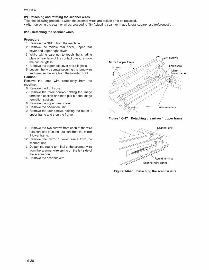
2CJ/2FA
1-6-30
(2) Detaching and refitting the scanner wiresTake the following procedure when the scanner wires are broken or to be replaced.• After replacing the scanner wires, proceed to “(6) Adjusting scanner image lateral squareness (reference)”.
(2-1) Detaching the scanner wires
Procedure1. Remove the SRDF from the machine.2. Remove the middle rear cover, upper rear
cover and upper right cover.3. While taking care not to touch the shading
plate or rear face of the contact glass, removethe contact glass.
4. Remove the upper left cover and slit glass.5. Loosen the two screws securing the lamp wire
and remove the wire from the inverter PCB.Caution:Remove the lamp wire completely from themachine.
6. Remove the front cover.7. Remove the three screws holding the image
formation section and then pull out the imageformation section.
8. Remove the upper inner cover.9. Remove the operation unit.
10. Remove the four screws holding the mirror 1upper frame and then the frame.
11. Remove the two screws from each of the wireretainers and then the retainers from the mirror1 lower frame.
12. Remove the mirror 1 lower frame from thescanner unit.
13. Detach the round terminal of the scanner wirefrom the scanner wire spring on the left side ofthe scanner unit.
14. Remove the scanner wire.
Figure 1-6-48 Detaching the scanner wire
Mirror 1 upper frameLamp wireScrews
Screws
Mirror 1 lower frame
Wire retainers
Figure 1-6-47 Detaching the mirror 1 upper frame
Scanner wire spring
Round terminal
Scanner unit
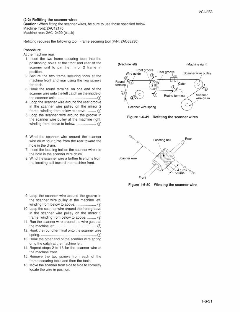
2CJ/2FA
1-6-31
(2-2) Refitting the scanner wiresCaution: When fitting the scanner wires, be sure to use those specified below.Machine front: 2AC12170Machine rear: 2AC12420 (black)
Refitting requires the following tool: Frame securing tool (P/N: 2AC68230)
ProcedureAt the machine rear:
1. Insert the two frame securing tools into thepositioning holes at the front and rear of thescanner unit to pin the mirror 2 frame inposition.
2. Secure the two frame securing tools at themachine front and rear using the two screwsfor each.
3. Hook the round terminal on one end of thescanner wire onto the left catch on the inside ofthe scanner unit. ........................................1
4. Loop the scanner wire around the rear groovein the scanner wire pulley on the mirror 2frame, winding from below to above. ........ 2
5. Loop the scanner wire around the groove inthe scanner wire pulley at the machine right,winding from above to below. ................... 3
6. Wind the scanner wire around the scannerwire drum four turns from the rear toward thehole in the drum.
7. Insert the locating ball on the scanner wire intothe hole in the scanner wire drum.
8. Wind the scanner wire a further five turns fromthe locating ball toward the machine front.
Figure 1-6-50 Winding the scanner wire
9. Loop the scanner wire around the groove inthe scanner wire pulley at the machine left,winding from below to above. .................... 4
10. Loop the scanner wire around the front groovein the scanner wire pulley on the mirror 2frame, winding from below to above. ......... 5
11. Run the scanner wire around the wire guide atthe machine left. .........................................6
12. Hook the round terminal onto the scanner wirespring. .........................................................7
13. Hook the other end of the scanner wire springonto the catch at the machine left.
14. Repeat steps 2 to 13 for the scanner wire atthe machine front.
15. Remove the two screws from each of theframe securing tools and then the tools.
16. Move the scanner from side to side to correctlylocate the wire in position.
Rear groove
(Machine left) (Machine right)
4
2
5
31
Scanner wire spring
Wire guide6
7
Front groove
Scanner wire drum
Catch
Scanner wire pulley
Round terminal
Round terminal
Figure 1-6-49 Refitting the scanner wires
4 turns5 turns
Scanner wire
Rear
Front
Locating ball
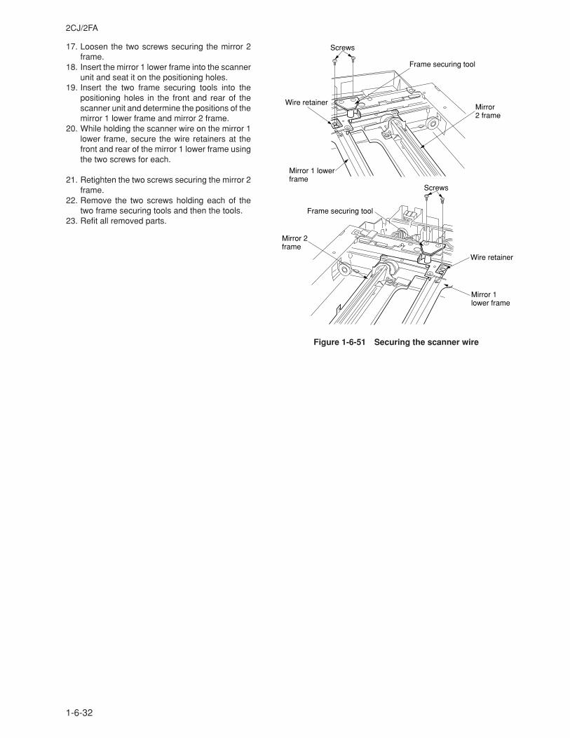
2CJ/2FA
1-6-32
17. Loosen the two screws securing the mirror 2frame.
18. Insert the mirror 1 lower frame into the scannerunit and seat it on the positioning holes.
19. Insert the two frame securing tools into thepositioning holes in the front and rear of thescanner unit and determine the positions of themirror 1 lower frame and mirror 2 frame.
20. While holding the scanner wire on the mirror 1lower frame, secure the wire retainers at thefront and rear of the mirror 1 lower frame usingthe two screws for each.
21. Retighten the two screws securing the mirror 2frame.
22. Remove the two screws holding each of thetwo frame securing tools and then the tools.
23. Refit all removed parts.
Figure 1-6-51 Securing the scanner wire
Screws
Screws
Frame securing tool
Mirror 2 frame
Wire retainer
Mirror 1 lower frame
Wire retainer
Frame securing tool
Mirror 2 frame
Mirror 1 lowerframe
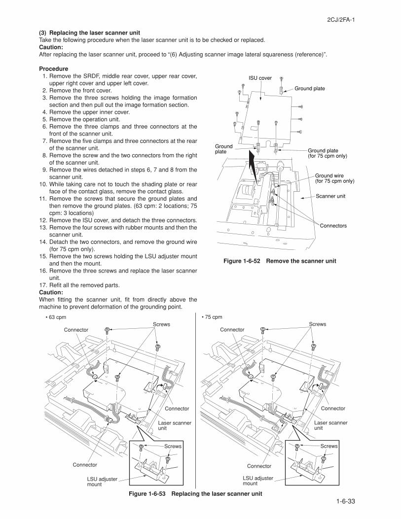
2CJ/2FA-1
1-6-33
(3) Replacing the laser scanner unitTake the following procedure when the laser scanner unit is to be checked or replaced.Caution:After replacing the laser scanner unit, proceed to “(6) Adjusting scanner image lateral squareness (reference)”.
Procedure1. Remove the SRDF, middle rear cover, upper rear cover,
upper right cover and upper left cover.2. Remove the front cover.3. Remove the three screws holding the image formation
section and then pull out the image formation section.4. Remove the upper inner cover.5. Remove the operation unit.6. Remove the three clamps and three connectors at the
front of the scanner unit.7. Remove the five clamps and three connectors at the rear
of the scanner unit.8. Remove the screw and the two connectors from the right
of the scanner unit.9. Remove the wires detached in steps 6, 7 and 8 from the
scanner unit.10. While taking care not to touch the shading plate or rear
face of the contact glass, remove the contact glass.11. Remove the screws that secure the ground plates and
then remove the ground plates. (63 cpm: 2 locations; 75cpm: 3 locations)
12. Remove the ISU cover, and detach the three connectors.13. Remove the four screws with rubber mounts and then the
scanner unit.14. Detach the two connectors, and remove the ground wire
(for 75 cpm only).15. Remove the two screws holding the LSU adjuster mount
and then the mount.16. Remove the three screws and replace the laser scanner
unit.17. Refit all the removed parts.Caution:When fitting the scanner unit, fit from directly above themachine to prevent deformation of the grounding point.
ISU cover
Ground plate
Ground plate(for 75 cpm only)
Ground wire(for 75 cpm only)
Ground plate
Connectors
Scanner unit
Figure 1-6-53 Replacing the laser scanner unit
Figure 1-6-52 Remove the scanner unit
Connector
Connector
Laser scannerunit
ConnectorScrews
Screws
LSU adjuster mount
Connector
Connector
Laser scannerunit
Connector
• 75 cpm• 63 cpmScrews
Screws
LSU adjuster mount
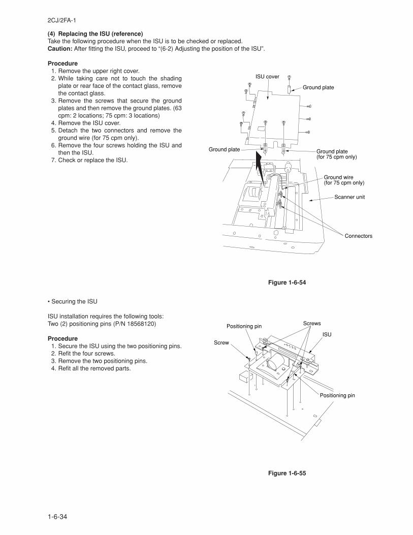
2CJ/2FA-1
1-6-34
(4) Replacing the ISU (reference)Take the following procedure when the ISU is to be checked or replaced.Caution: After fitting the ISU, proceed to “(6-2) Adjusting the position of the ISU”.
Procedure1. Remove the upper right cover.2. While taking care not to touch the shading
plate or rear face of the contact glass, removethe contact glass.
3. Remove the screws that secure the groundplates and then remove the ground plates. (63cpm: 2 locations; 75 cpm: 3 locations)
4. Remove the ISU cover.5. Detach the two connectors and remove the
ground wire (for 75 cpm only).6. Remove the four screws holding the ISU and
then the ISU.7. Check or replace the ISU.
Figure 1-6-54
• Securing the ISU
ISU installation requires the following tools:Two (2) positioning pins (P/N 18568120)
Procedure1. Secure the ISU using the two positioning pins.2. Refit the four screws.3. Remove the two positioning pins.4. Refit all the removed parts.
Figure 1-6-55
ISU
Positioning pin
Positioning pin
Screw
Screws
Connectors
Scanner unit
ISU cover
Ground plate
Ground plate(for 75 cpm only)
Ground plate
Ground wire(for 75 cpm only)
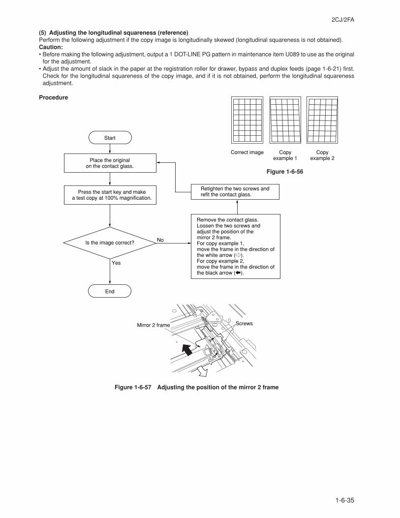
2CJ/2FA
1-6-35
(5) Adjusting the longitudinal squareness (reference)Perform the following adjustment if the copy image is longitudinally skewed (longitudinal squareness is not obtained).Caution:• Before making the following adjustment, output a 1 DOT-LINE PG pattern in maintenance item U089 to use as the original
for the adjustment.• Adjust the amount of slack in the paper at the registration roller for drawer, bypass and duplex feeds (page 1-6-21) first.
Check for the longitudinal squareness of the copy image, and if it is not obtained, perform the longitudinal squarenessadjustment.
Procedure
Yes
No
Press the start key and make a test copy at 100% magnification.
Start
Remove the contact glass. Loosen the two screws and adjust the position of the mirror 2 frame.For copy example 1, move the frame in the direction of the white arrow (e).For copy example 2, move the frame in the direction of the black arrow (b).
End
Is the image correct?
Place the original on the contact glass.
Retighten the two screws and refit the contact glass.
ScrewsMirror 2 frame
Figure 1-6-57 Adjusting the position of the mirror 2 frame
Correct image Copy example 1
Copy example 2
Figure 1-6-56
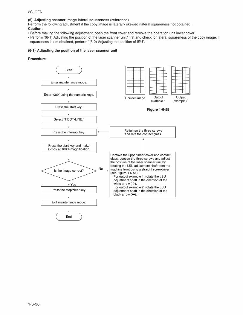
2CJ/2FA
1-6-36
(6) Adjusting scanner image lateral squareness (reference)Perform the following adjustment if the copy image is laterally skewed (lateral squareness not obtained).Caution:• Before making the following adjustment, open the front cover and remove the operation unit lower cover.• Perform “(6-1) Adjusting the position of the laser scanner unit” first and check for lateral squareness of the copy image. If
squareness is not obtained, perform “(6-2) Adjusting the position of ISU”.
(6-1) Adjusting the position of the laser scanner unit
Procedure
Retighten the three screws and refit the contact glass.
Yes
No
Press the start key and make a copy at 100% magnification.
Start
End
Is the image correct?
Enter maintenance mode.
Enter “089” using the numeric keys.
Press the interrupt key.
Select “1 DOT-LINE.”
Press the start key.
Exit maintenance mode.
Press the stop/clear key.
Remove the upper inner cover and contact glass. Loosen the three screws and adjust the position of the laser scanner unit by rotating the LSU adjustment shaft from the machine front using a straight screwdriver (see Figure 1-6-51).
For output example 1, rotate the LSU adjustment shaft in the direction of the white arrow (e).For output example 2, rotate the LSU adjustment shaft in the direction of the black arrow (b).
Correct image Output example 1
Output example 2
Figure 1-6-58
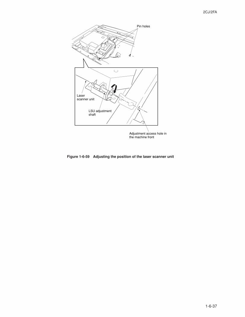
2CJ/2FA
1-6-37
Figure 1-6-59 Adjusting the position of the laser scanner unit
Pin holes
Laser scanner unit
LSU adjustment shaft
Adjustment access hole in the machine front
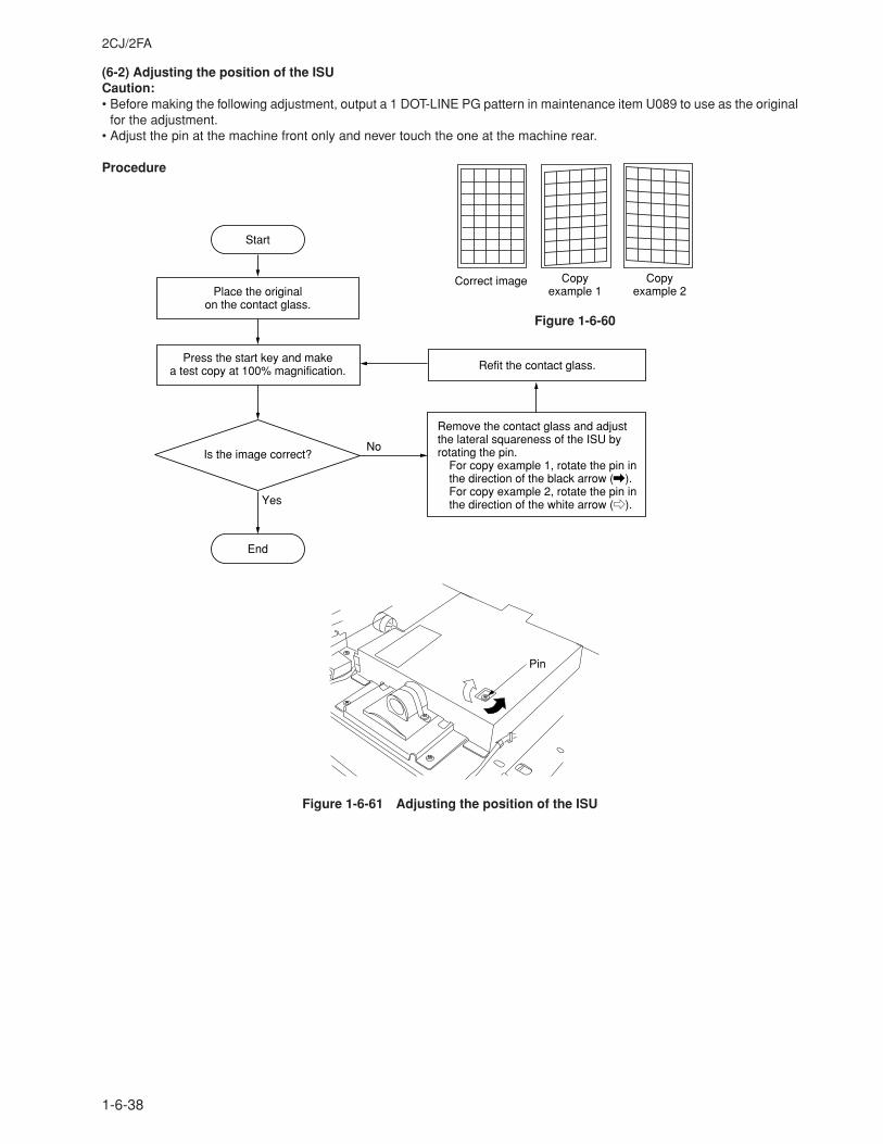
2CJ/2FA
1-6-38
(6-2) Adjusting the position of the ISUCaution:• Before making the following adjustment, output a 1 DOT-LINE PG pattern in maintenance item U089 to use as the original
for the adjustment.• Adjust the pin at the machine front only and never touch the one at the machine rear.
Procedure
Refit the contact glass.
Remove the contact glass and adjust the lateral squareness of the ISU by rotating the pin.
For copy example 1, rotate the pin in the direction of the black arrow (\).For copy example 2, rotate the pin in the direction of the white arrow (e).Yes
No
Press the start key and make a test copy at 100% magnification.
Start
End
Is the image correct?
Place the original on the contact glass.
Pin
Figure 1-6-61 Adjusting the position of the ISU
Correct image Copy example 1
Copy example 2
Figure 1-6-60
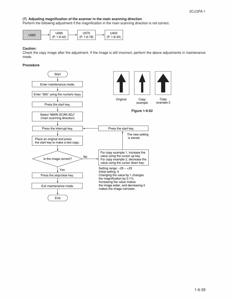
2CJ/2FA-1
1-6-39
(7) Adjusting magnification of the scanner in the main scanning directionPerform the following adjustment if the magnification in the main scanning direction is not correct.
U065U070
(P. 1-6-78)U066
(P. 1-6-42)U403
(P. 1-6-43)
Caution:Check the copy image after the adjustment. If the image is still incorrect, perform the above adjustments in maintenancemode.
Procedure
Enter maintenance mode.
Enter “065” using the numeric keys.
Yes
No
Start
End
Press the interrupt key.
Exit maintenance mode.
Place an original and press the start key to make a test copy.
Is the image correct?
Setting range: –25 – +25Initial setting: 0Changing the value by 1 changes the magnification by 0.1%.Increasing the value makes the image wider, and decreasing it makes the image narrower.
For copy example 1, increase the value using the cursor up key.For copy example 2, decrease the value using the cursor down key.
Press the start key.
The new setting is stored.
Select “MAIN SCAN ADJ” (main scanning direction).
Press the start key.
Press the stop/clear key.
Original Copyexample
Copyexample 2
Figure 1-6-62
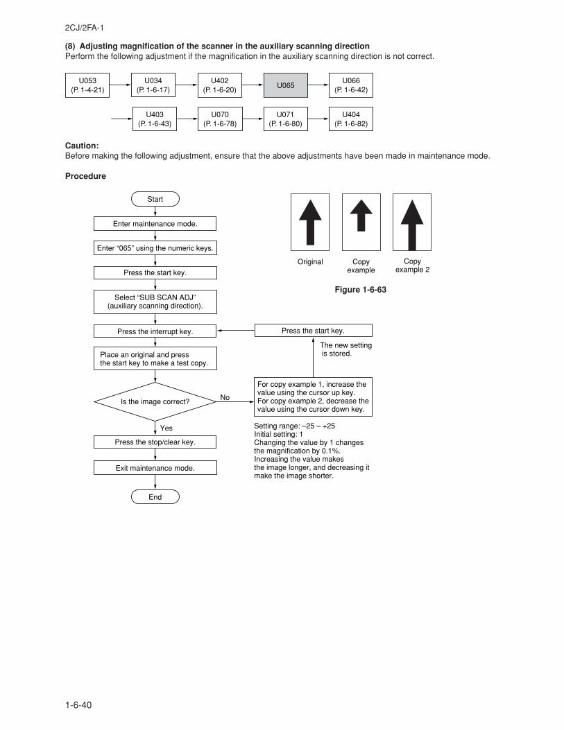
2CJ/2FA-1
1-6-40
(8) Adjusting magnification of the scanner in the auxiliary scanning directionPerform the following adjustment if the magnification in the auxiliary scanning direction is not correct.
U053(P. 1-4-21)
U403(P. 1-6-43)
U402(P. 1-6-20)
U066(P. 1-6-42)
U070(P. 1-6-78)
U071(P. 1-6-80)
U404(P. 1-6-82)
U065U034
(P. 1-6-17)
Caution:Before making the following adjustment, ensure that the above adjustments have been made in maintenance mode.
Procedure
Original Copyexample
Copyexample 2
Enter maintenance mode.
Enter “065” using the numeric keys.
Yes
No
Start
End
Press the interrupt key.
Exit maintenance mode.
Place an original and press the start key to make a test copy.
Is the image correct?
Setting range: –25 – +25Initial setting: 1Changing the value by 1 changes the magnification by 0.1%.Increasing the value makes the image longer, and decreasing it make the image shorter.
For copy example 1, increase the value using the cursor up key.For copy example 2, decrease the value using the cursor down key.
Press the start key.
The new setting is stored.
Press the start key.
Press the stop/clear key.
Select “SUB SCAN ADJ” (auxiliary scanning direction).
Figure 1-6-63
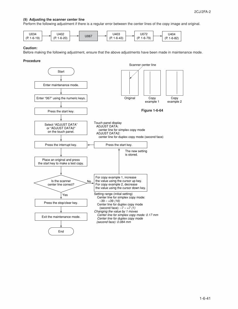
2CJ/2FA-2
1-6-41
(9) Adjusting the scanner center linePerform the following adjustment if there is a regular error between the center lines of the copy image and original.
U034(P. 1-6-19)
U404(P. 1-6-82)
U067U072
(P. 1-6-79)U403
(P. 1-6-43)U402
(P. 1-6-20)
Caution:Before making the following adjustment, ensure that the above adjustments have been made in maintenance mode.
Procedure
Original Copy example 1
Copy example 2
Scanner center line
Yes
No
Start
Enter maintenance mode.
Enter “067” using the numeric keys.
Press the start key.
Select “ADJUST DATA” or “ADJUST DATA2” on the touch panel.
Press the interrupt key.
Place an original and press the start key to make a test copy.
Is the scanner center line correct?
For copy example 1, increase the value using the cursor up key.For copy example 2, decrease the value using the cursor down key.
Press the start key.
The new settingis stored.
Press the stop/clear key.
Exit the maintenance mode.
Setting range (initial setting)Center line for simplex copy mode:
–39 – +39 (16)Center line for duplex copy mode
(second face): –7 – +7 (1)Changing the value by 1 moves
Center line for simplex copy mode: 0.17 mmCenter line for duplex copy mode (second face): 0.084 mm
End
Touch panel displayADJUST DATA:
center line for simplex copy modeADJUST DATA2:
center line for duplex copy mode (second face)
Figure 1-6-64
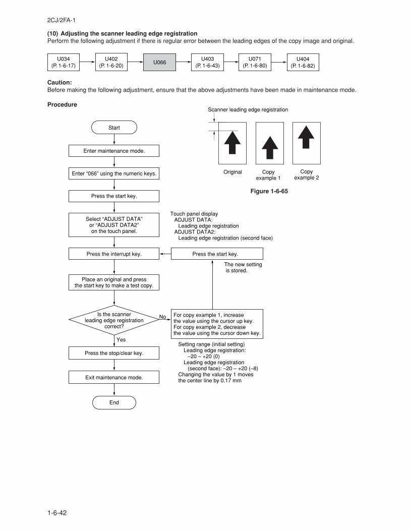
2CJ/2FA-1
1-6-42
(10) Adjusting the scanner leading edge registrationPerform the following adjustment if there is regular error between the leading edges of the copy image and original.
U034(P. 1-6-17)
U404(P. 1-6-82)
U066U071
(P. 1-6-80)U403
(P. 1-6-43)U402
(P. 1-6-20)
Caution:Before making the following adjustment, ensure that the above adjustments have been made in maintenance mode.
Procedure
Is the scanner leading edge registration
correct?
Yes
No
Start
Enter maintenance mode.
Enter “066” using the numeric keys.
Press the start key.
Press the interrupt key.
Place an original and press the start key to make a test copy.
For copy example 1, increase the value using the cursor up key.For copy example 2, decrease the value using the cursor down key.
Press the start key.
The new setting is stored.
Press the stop/clear key.
Exit maintenance mode.
End
Setting range (initial setting)Leading edge registration:
–20 – +20 (0)Leading edge registration
(second face): –20 – +20 (–8)Changing the value by 1 moves the center line by 0.17 mm
Touch panel displayADJUST DATA:
Leading edge registrationADJUST DATA2:
Leading edge registration (second face)
Select “ADJUST DATA” or “ADJUST DATA2” on the touch panel.
Original Copy example 1
Copy example 2
Scanner leading edge registration
Figure 1-6-65
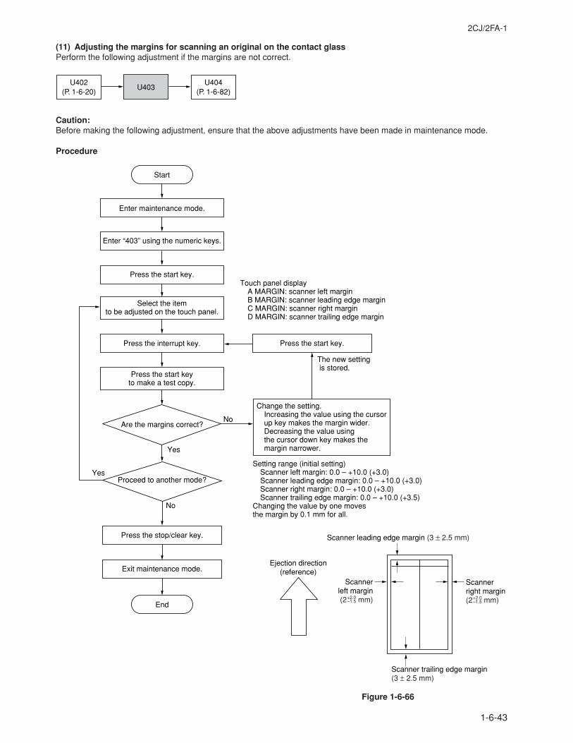
2CJ/2FA-1
1-6-43
(11) Adjusting the margins for scanning an original on the contact glassPerform the following adjustment if the margins are not correct.
U402(P. 1-6-20)
U404(P. 1-6-82)
U403
Caution:Before making the following adjustment, ensure that the above adjustments have been made in maintenance mode.
Procedure
Change the setting.Increasing the value using the cursor up key makes the margin wider.Decreasing the value using the cursor down key makes the margin narrower.Yes
No
Start
Enter maintenance mode.
Enter “403” using the numeric keys.
Press the start key.
Press the start key to make a test copy.
Press the start key.
The new setting is stored.
Setting range (initial setting)Scanner left margin: 0.0 – +10.0 (+3.0)Scanner leading edge margin: 0.0 – +10.0 (+3.0)Scanner right margin: 0.0 – +10.0 (+3.0)Scanner trailing edge margin: 0.0 – +10.0 (+3.5)
Changing the value by one moves the margin by 0.1 mm for all.
Select the item to be adjusted on the touch panel.
Are the margins correct?
Press the interrupt key.
Touch panel displayA MARGIN: scanner left marginB MARGIN: scanner leading edge marginC MARGIN: scanner right marginD MARGIN: scanner trailing edge margin
Yes
No
Press the stop/clear key.
Exit maintenance mode.
End
Proceed to another mode?
Scanner leading edge margin (3 ± 2.5 mm)
Scannerleft margin(2+2.0 mm)
Scanner right margin(2+2.0 mm)
Ejection direction(reference)
Scanner trailing edge margin(3 ± 2.5 mm)
–1.5–1.5
Figure 1-6-66
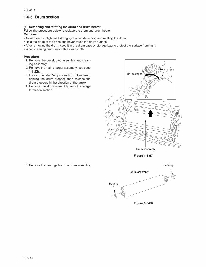
2CJ/2FA
1-6-44
1-6-5 Drum section
(1) Detaching and refitting the drum and drum heaterFollow the procedure below to replace the drum and drum heater.Cautions:• Avoid direct sunlight and strong light when detaching and refitting the drum.• Hold the drum at the ends and never touch the drum surface.• After removing the drum, keep it in the drum case or storage bag to protect the surface from light.• When cleaning drum, rub with a clean cloth.
Procedure1. Remove the developing assembly and clean-
ing assembly.2. Remove the main charger assembly (see page
1-6-22).3. Loosen the retain5er pins each (front and rear)
holding the drum stopper, then release thedrum stoppers in the direction of the arrow.
4. Remove the drum assembly from the imageformation section.
Figure 1-6-67
5. Remove the bearings from the drum assembly.
Figure 1-6-68
Drum stopper
Retainer pin
Drum assembly
Bearing
Bearing
Drum assembly
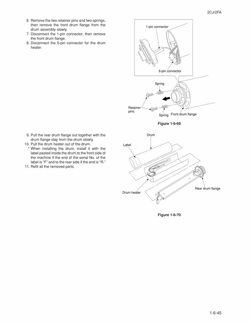
2CJ/2FA
1-6-45
6. Remove the two retainer pins and two springs,then remove the front drum flange from thedrum assembly slowly.
7. Disconnect the 1-pin connector, then removethe front drum flange.
8. Disconnect the 6-pin connector for the drumheater.
Figure 1-6-69
9. Pull the rear drum flange out together with thedrum flange stay from the drum slowly.
10. Pull the drum heater out of the drum.* When installing the drum, install it with the
label pasted inside the drum to the front side ofthe machine if the end of the serial No. of thelabel is “F” and to the rear side if the end is “R.”
11. Refit all the removed parts.
Figure 1-6-70
Spring
Front drum flangeSpring
Retainer pins
1-pin connector
6-pin connector
Drum
Drum heaterRear drum flange
Label
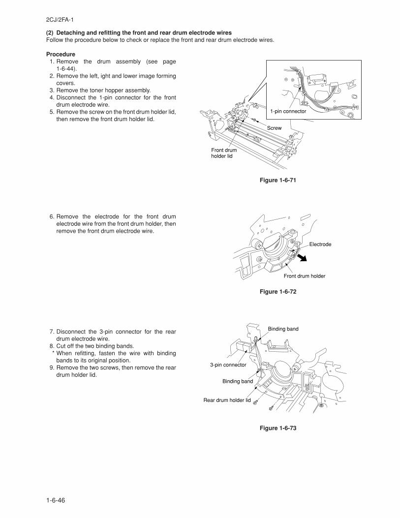
2CJ/2FA-1
1-6-46
(2) Detaching and refitting the front and rear drum electrode wiresFollow the procedure below to check or replace the front and rear drum electrode wires.
Procedure1. Remove the drum assembly (see page
1-6-44).2. Remove the left, ight and lower image forming
covers.3. Remove the toner hopper assembly.4. Disconnect the 1-pin connector for the front
drum electrode wire.5. Remove the screw on the front drum holder lid,
then remove the front drum holder lid.
6. Remove the electrode for the front drumelectrode wire from the front drum holder, thenremove the front drum electrode wire.
Figure 1-6-72
7. Disconnect the 3-pin connector for the reardrum electrode wire.
8. Cut off the two binding bands.* When refitting, fasten the wire with binding
bands to its original position.9. Remove the two screws, then remove the rear
drum holder lid.
Figure 1-6-73
1-pin connector
Screw
Front drumholder lid
Figure 1-6-71
Front drum holder
Electrode
3-pin connector
Binding band
Binding band
Rear drum holder lid
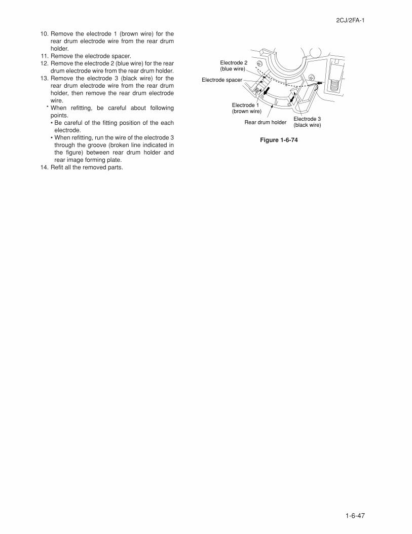
2CJ/2FA-1
1-6-47
10. Remove the electrode 1 (brown wire) for therear drum electrode wire from the rear drumholder.
11. Remove the electrode spacer.12. Remove the electrode 2 (blue wire) for the rear
drum electrode wire from the rear drum holder.13. Remove the electrode 3 (black wire) for the
rear drum electrode wire from the rear drumholder, then remove the rear drum electrodewire.
* When refitting, be careful about followingpoints.• Be careful of the fitting position of the each
electrode.• When refitting, run the wire of the electrode 3
through the groove (broken line indicated inthe figure) between rear drum holder andrear image forming plate.
14. Refit all the removed parts.
Electrode 2(blue wire)
Electrode spacer
Electrode 1(brown wire)
Electrode 3(black wire)Rear drum holder
Figure 1-6-74
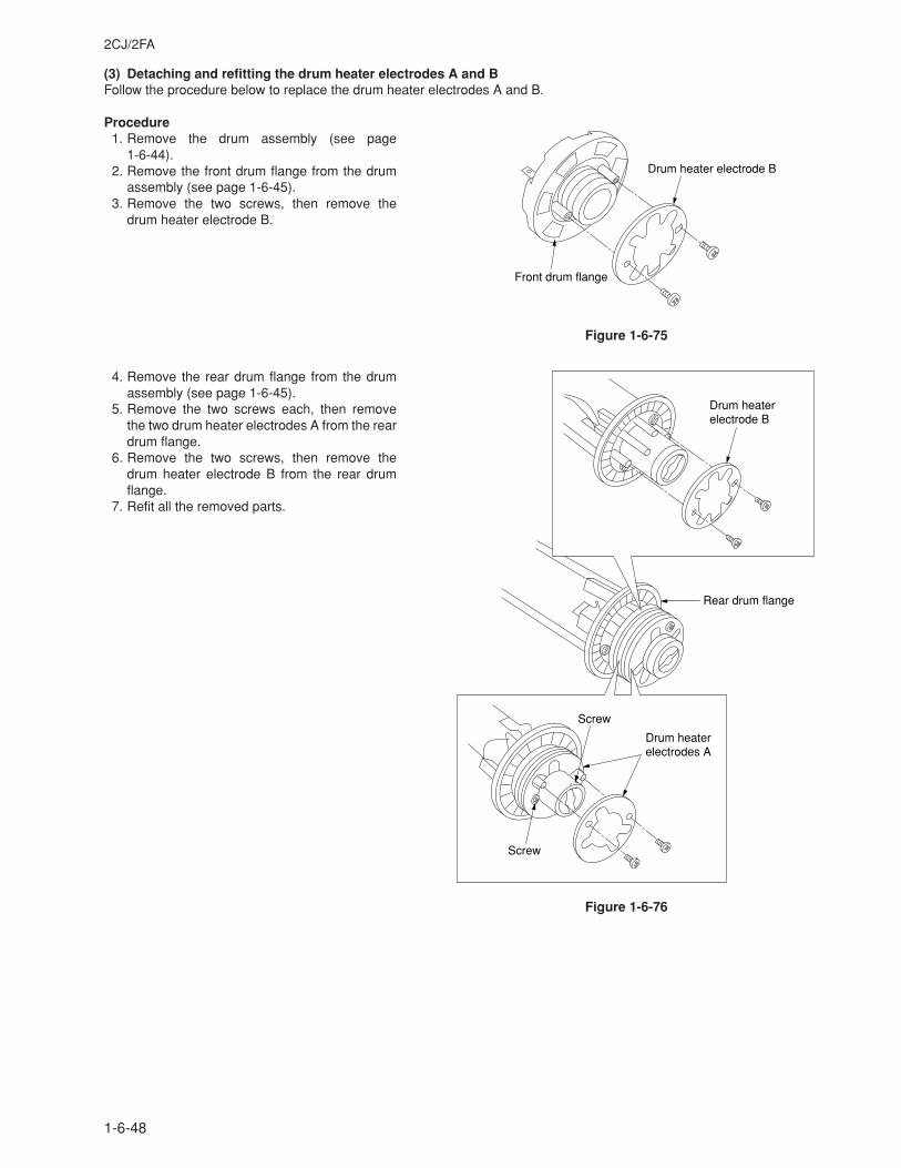
2CJ/2FA
1-6-48
(3) Detaching and refitting the drum heater electrodes A and BFollow the procedure below to replace the drum heater electrodes A and B.
Procedure1. Remove the drum assembly (see page
1-6-44).2. Remove the front drum flange from the drum
assembly (see page 1-6-45).3. Remove the two screws, then remove the
drum heater electrode B.
Figure 1-6-75
4. Remove the rear drum flange from the drumassembly (see page 1-6-45).
5. Remove the two screws each, then removethe two drum heater electrodes A from the reardrum flange.
6. Remove the two screws, then remove thedrum heater electrode B from the rear drumflange.
7. Refit all the removed parts.
Figure 1-6-76
Drum heater electrode B
Front drum flange
Drum heater electrodes A
Drum heater electrode B
Rear drum flange
Screw
Screw
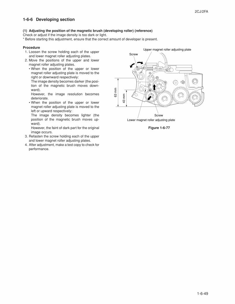
2CJ/2FA
1-6-49
1-6-6 Developing section
(1) Adjusting the position of the magnetic brush (developing roller) (reference)Check or adjust if the image density is too dark or light.* Before starting this adjustment, ensure that the correct amount of developer is present.
Procedure1. Loosen the screw holding each of the upper
and lower magnet roller adjusting plates.2. Move the positions of the upper and lower
magnet roller adjusting plates.• When the position of the upper or lower
magnet roller adjusting plate is moved to theright or downward respectively:The image density becomes darker (the posi-tion of the magnetic brush moves down-ward).However, the image resolution becomesdeteriorate.
• When the position of the upper or lowermagnet roller adjusting plate is moved to theleft or upward respectively:The image density becomes lighter (theposition of the magnetic brush moves up-ward).However, the faint of dark part for the originalimage occurs.
3. Refasten the screw holding each of the upperand lower magnet roller adjusting plates.
4. After adjustment, make a test copy to check forperformance.
Figure 1-6-77
Screw
Screw
Upper magnet roller adjusting plate
Lower magnet roller adjusting plate
63 m
m
43 m
m
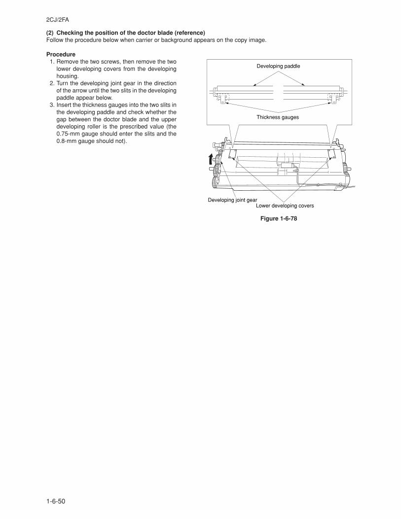
2CJ/2FA
1-6-50
(2) Checking the position of the doctor blade (reference)Follow the procedure below when carrier or background appears on the copy image.
Procedure1. Remove the two screws, then remove the two
lower developing covers from the developinghousing.
2. Turn the developing joint gear in the directionof the arrow until the two slits in the developingpaddle appear below.
3. Insert the thickness gauges into the two slits inthe developing paddle and check whether thegap between the doctor blade and the upperdeveloping roller is the prescribed value (the0.75-mm gauge should enter the slits and the0.8-mm gauge should not).
Figure 1-6-78
Developing joint gearLower developing covers
Developing paddle
Thickness gauges
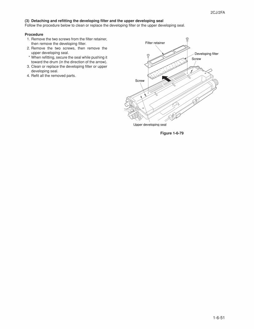
2CJ/2FA
1-6-51
(3) Detaching and refitting the developing filter and the upper developing sealFollow the procedure below to clean or replace the developing filter or the upper developing seal.
Procedure1. Remove the two screws from the filter retainer,
then remove the developing filter.2. Remove the two screws, then remove the
upper developing seal.* When refitting, secure the seal while pushing it
toward the drum (in the direction of the arrow).3. Clean or replace the developing filter or upper
developing seal.4. Refit all the removed parts.
Figure 1-6-79
Filter retainer
Developing filter
Upper developing seal
Screw
Screw
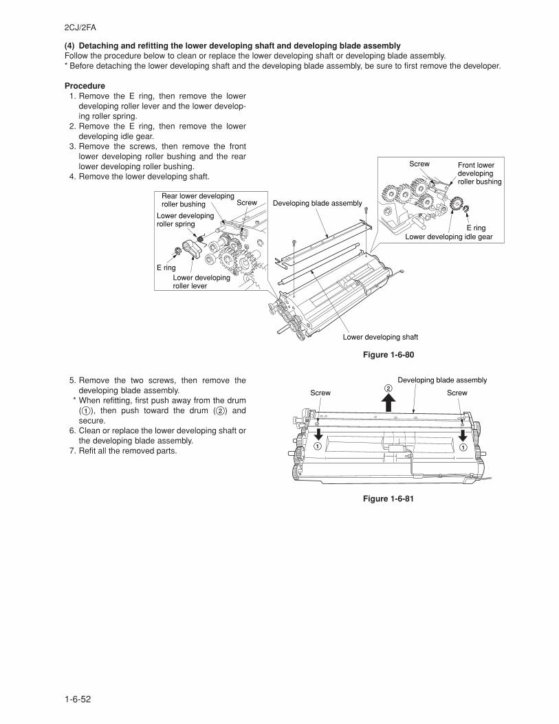
2CJ/2FA
1-6-52
(4) Detaching and refitting the lower developing shaft and developing blade assemblyFollow the procedure below to clean or replace the lower developing shaft or developing blade assembly.* Before detaching the lower developing shaft and the developing blade assembly, be sure to first remove the developer.
Procedure1. Remove the E ring, then remove the lower
developing roller lever and the lower develop-ing roller spring.
2. Remove the E ring, then remove the lowerdeveloping idle gear.
3. Remove the screws, then remove the frontlower developing roller bushing and the rearlower developing roller bushing.
4. Remove the lower developing shaft.
Figure 1-6-80
5. Remove the two screws, then remove thedeveloping blade assembly.
* When refitting, first push away from the drum(1), then push toward the drum (2) andsecure.
6. Clean or replace the lower developing shaft orthe developing blade assembly.
7. Refit all the removed parts.
Figure 1-6-81
Screw
Screw
E ring
E ring
Lower developing idle gear
Developing blade assembly
Lower developing roller spring
Lower developing roller lever
Front lower developing roller bushing
Lower developing shaft
Rear lower developing roller bushing
ScrewScrew
Developing blade assembly2
1 1
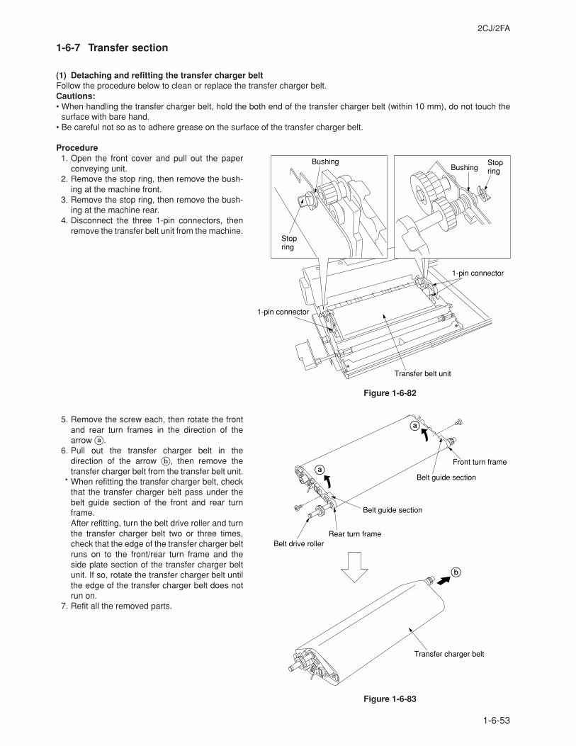
2CJ/2FA
1-6-53
1-6-7 Transfer section
(1) Detaching and refitting the transfer charger beltFollow the procedure below to clean or replace the transfer charger belt.Cautions:• When handling the transfer charger belt, hold the both end of the transfer charger belt (within 10 mm), do not touch the
surface with bare hand.• Be careful not so as to adhere grease on the surface of the transfer charger belt.
Procedure1. Open the front cover and pull out the paper
conveying unit.2. Remove the stop ring, then remove the bush-
ing at the machine front.3. Remove the stop ring, then remove the bush-
ing at the machine rear.4. Disconnect the three 1-pin connectors, then
remove the transfer belt unit from the machine.
Figure 1-6-82
5. Remove the screw each, then rotate the frontand rear turn frames in the direction of thearrow a.
6. Pull out the transfer charger belt in thedirection of the arrow b, then remove thetransfer charger belt from the transfer belt unit.
* When refitting the transfer charger belt, checkthat the transfer charger belt pass under thebelt guide section of the front and rear turnframe.After refitting, turn the belt drive roller and turnthe transfer charger belt two or three times,check that the edge of the transfer charger beltruns on to the front/rear turn frame and theside plate section of the transfer charger beltunit. If so, rotate the transfer charger belt untilthe edge of the transfer charger belt does notrun on.
7. Refit all the removed parts.
Figure 1-6-83
Transfer belt unit
1-pin connector
1-pin connector
Bushing
Stop ring
BushingStop ring
Belt guide section
Belt guide section
Belt drive rollerRear turn frame
Front turn frame
Transfer charger belt
a
b
a
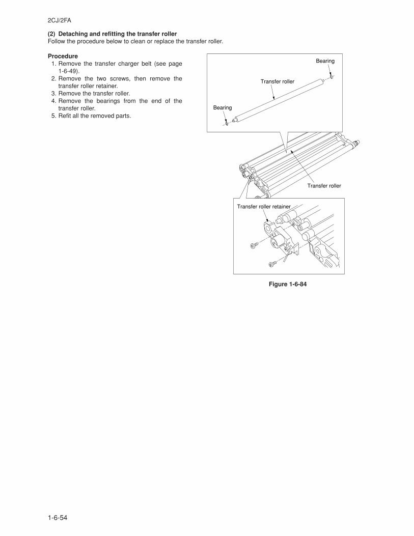
2CJ/2FA
1-6-54
(2) Detaching and refitting the transfer rollerFollow the procedure below to clean or replace the transfer roller.
Procedure1. Remove the transfer charger belt (see page
1-6-49).2. Remove the two screws, then remove the
transfer roller retainer.3. Remove the transfer roller.4. Remove the bearings from the end of the
transfer roller.5. Refit all the removed parts.
Figure 1-6-84
Transfer roller
Transfer roller
Bearing
Bearing
Transfer roller retainer
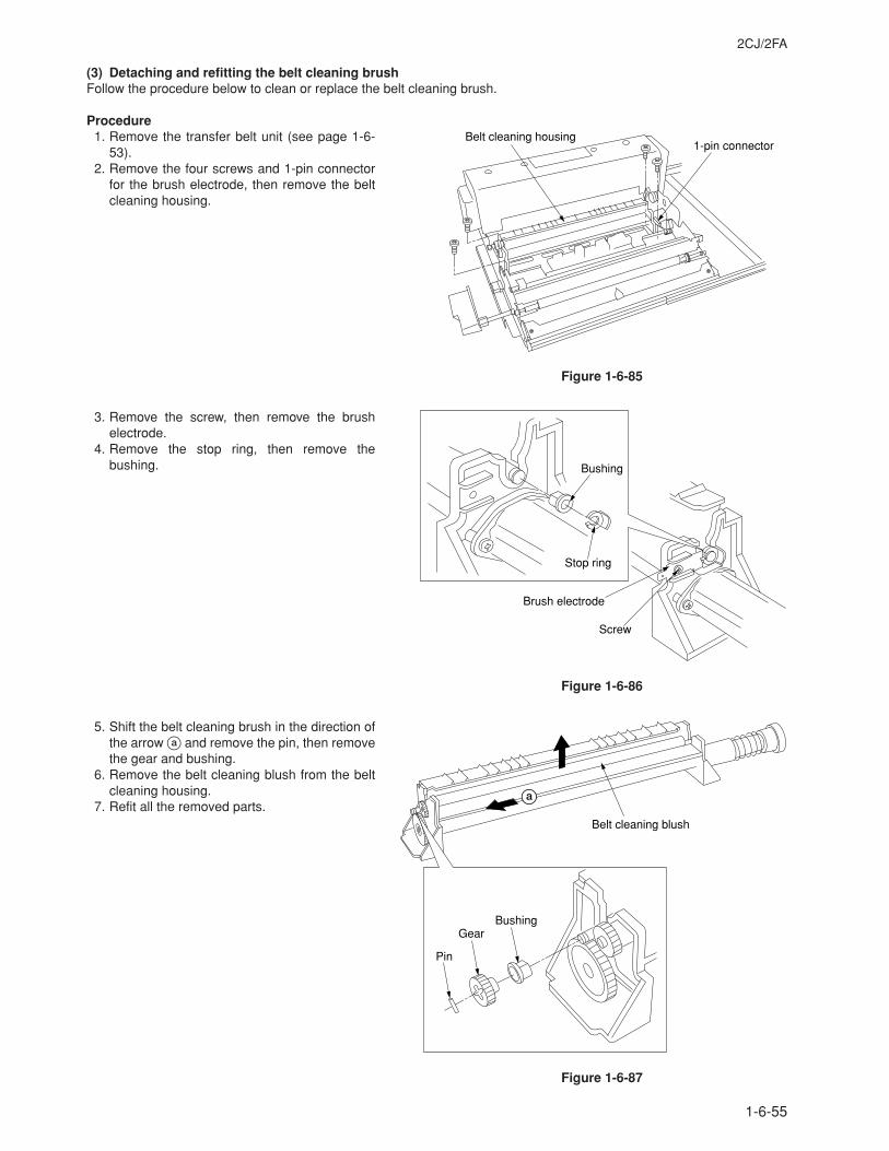
2CJ/2FA
1-6-55
(3) Detaching and refitting the belt cleaning brushFollow the procedure below to clean or replace the belt cleaning brush.
Procedure1. Remove the transfer belt unit (see page 1-6-
53).2. Remove the four screws and 1-pin connector
for the brush electrode, then remove the beltcleaning housing.
Figure 1-6-85
3. Remove the screw, then remove the brushelectrode.
4. Remove the stop ring, then remove thebushing.
Figure 1-6-86
5. Shift the belt cleaning brush in the direction ofthe arrow a and remove the pin, then removethe gear and bushing.
6. Remove the belt cleaning blush from the beltcleaning housing.
7. Refit all the removed parts.
Figure 1-6-87
Belt cleaning housing1-pin connector
Screw
Brush electrode
Bushing
Stop ring
Belt cleaning blush
BushingGear
Pin
a
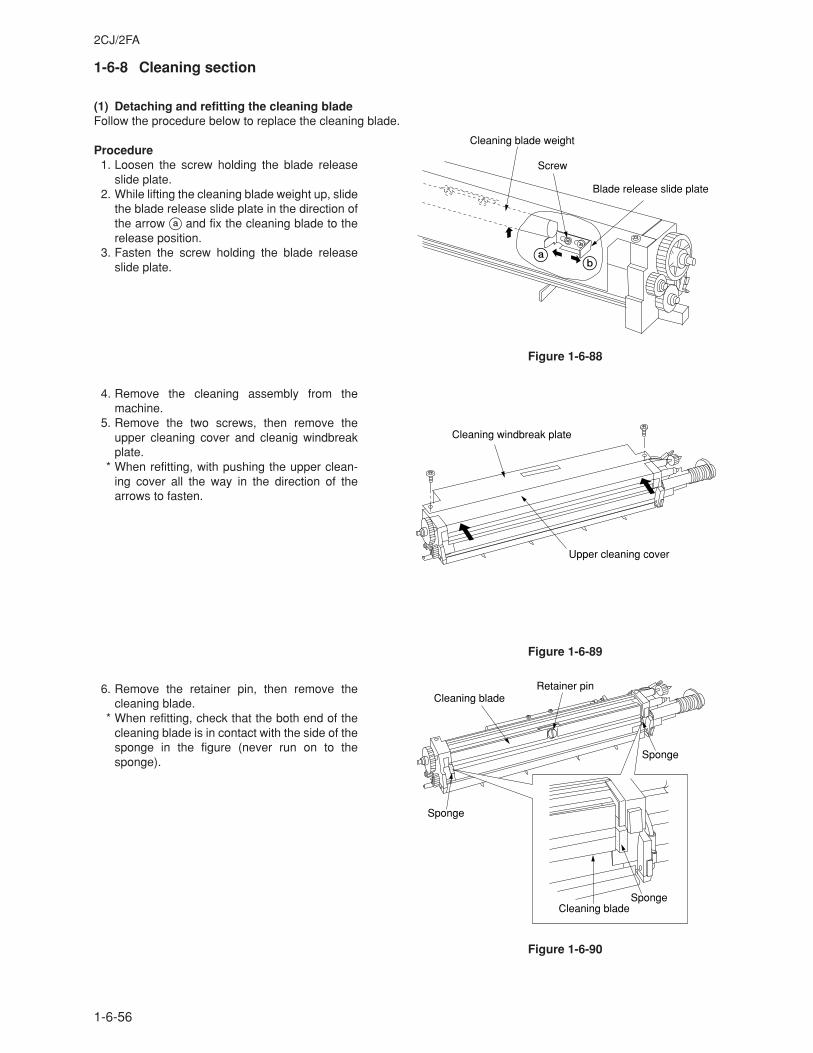
2CJ/2FA
1-6-56
1-6-8 Cleaning section
(1) Detaching and refitting the cleaning bladeFollow the procedure below to replace the cleaning blade.
Procedure1. Loosen the screw holding the blade release
slide plate.2. While lifting the cleaning blade weight up, slide
the blade release slide plate in the direction ofthe arrow a and fix the cleaning blade to therelease position.
3. Fasten the screw holding the blade releaseslide plate.
Figure 1-6-88
4. Remove the cleaning assembly from themachine.
5. Remove the two screws, then remove theupper cleaning cover and cleanig windbreakplate.
* When refitting, with pushing the upper clean-ing cover all the way in the direction of thearrows to fasten.
Figure 1-6-89
6. Remove the retainer pin, then remove thecleaning blade.
* When refitting, check that the both end of thecleaning blade is in contact with the side of thesponge in the figure (never run on to thesponge).
Figure 1-6-90
Screw
Blade release slide plate
ab
Cleaning blade weight
Upper cleaning cover
Cleaning windbreak plate
Retainer pinCleaning blade
Sponge
Sponge
Cleaning bladeSponge
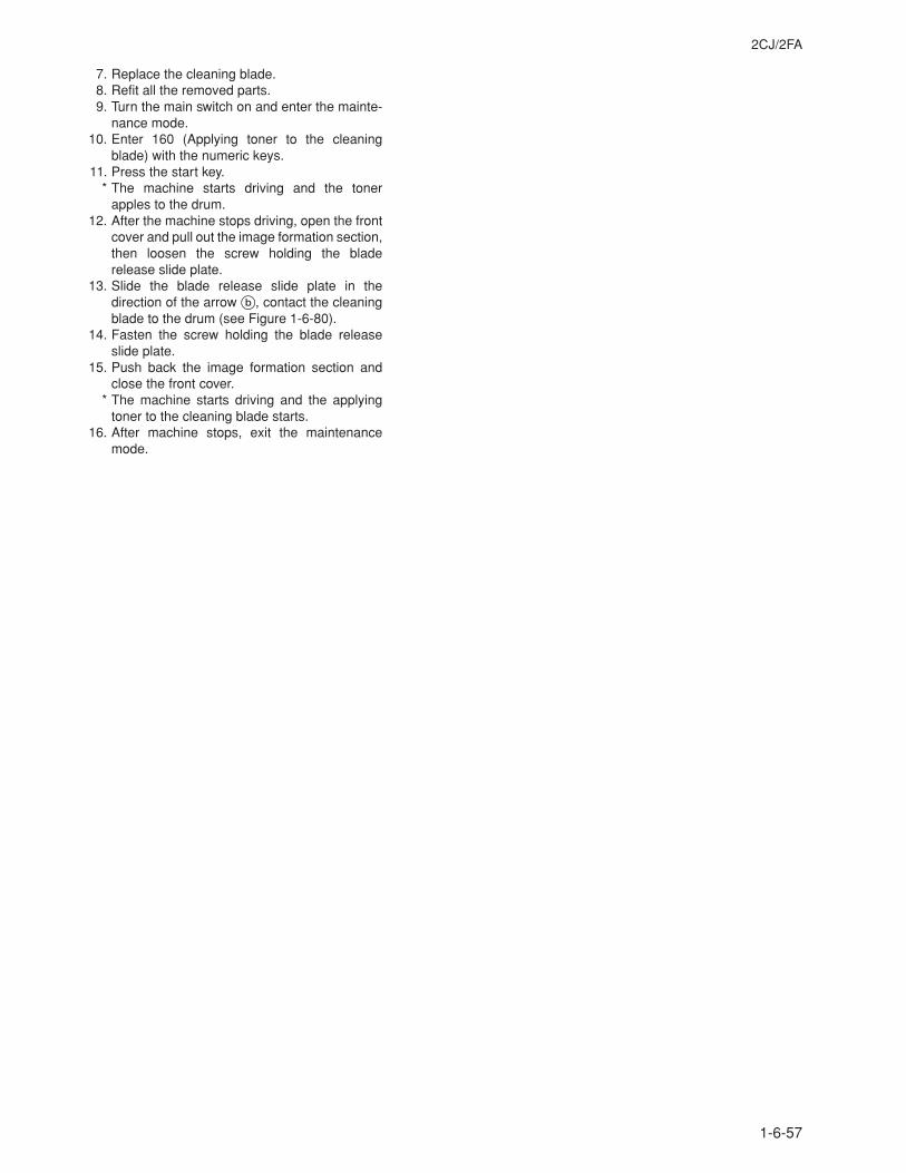
2CJ/2FA
1-6-57
7. Replace the cleaning blade.8. Refit all the removed parts.9. Turn the main switch on and enter the mainte-
nance mode.10. Enter 160 (Applying toner to the cleaning
blade) with the numeric keys.11. Press the start key.
* The machine starts driving and the tonerapples to the drum.
12. After the machine stops driving, open the frontcover and pull out the image formation section,then loosen the screw holding the bladerelease slide plate.
13. Slide the blade release slide plate in thedirection of the arrow b, contact the cleaningblade to the drum (see Figure 1-6-80).
14. Fasten the screw holding the blade releaseslide plate.
15. Push back the image formation section andclose the front cover.
* The machine starts driving and the applyingtoner to the cleaning blade starts.
16. After machine stops, exit the maintenancemode.
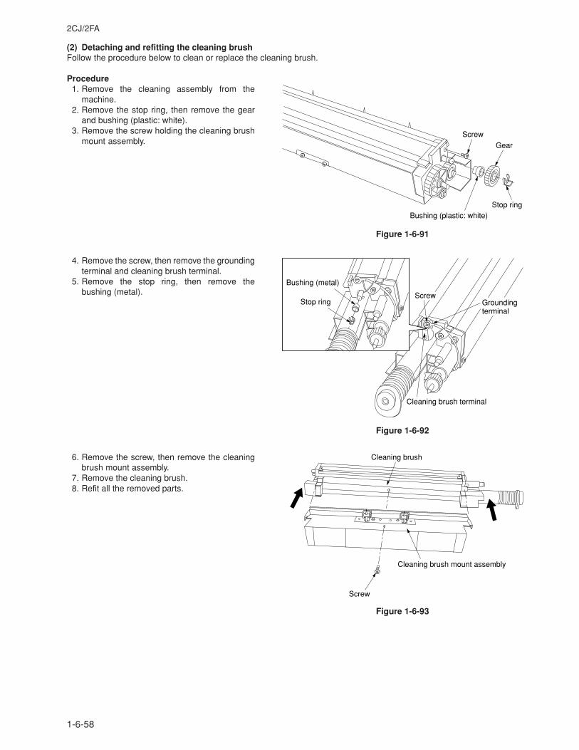
2CJ/2FA
1-6-58
(2) Detaching and refitting the cleaning brushFollow the procedure below to clean or replace the cleaning brush.
Procedure1. Remove the cleaning assembly from the
machine.2. Remove the stop ring, then remove the gear
and bushing (plastic: white).3. Remove the screw holding the cleaning brush
mount assembly.
Figure 1-6-91
4. Remove the screw, then remove the groundingterminal and cleaning brush terminal.
5. Remove the stop ring, then remove thebushing (metal).
Figure 1-6-92
6. Remove the screw, then remove the cleaningbrush mount assembly.
7. Remove the cleaning brush.8. Refit all the removed parts.
Figure 1-6-93
Screw
Gear
Bushing (plastic: white)Stop ring
ScrewGrounding terminal
Cleaning brush terminal
Bushing (metal)
Stop ring
Cleaning brush
Cleaning brush mount assembly
Screw
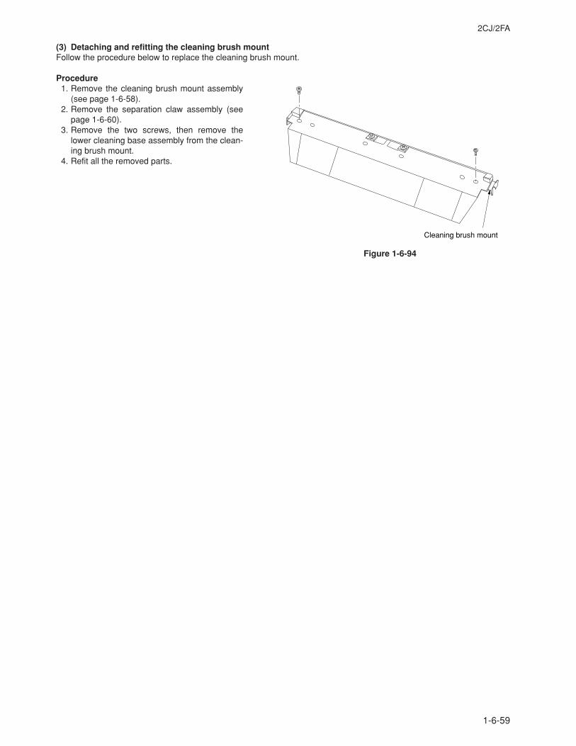
2CJ/2FA
1-6-59
(3) Detaching and refitting the cleaning brush mountFollow the procedure below to replace the cleaning brush mount.
Procedure1. Remove the cleaning brush mount assembly
(see page 1-6-58).2. Remove the separation claw assembly (see
page 1-6-60).3. Remove the two screws, then remove the
lower cleaning base assembly from the clean-ing brush mount.
4. Refit all the removed parts.
Figure 1-6-94
Cleaning brush mount
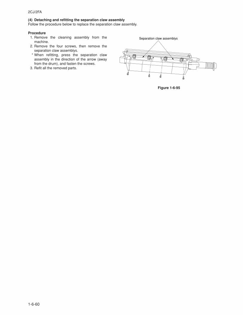
2CJ/2FA
1-6-60
(4) Detaching and refitting the separation claw assemblyFollow the procedure below to replace the separation claw assembly.
Procedure1. Remove the cleaning assembly from the
machine.2. Remove the four screws, then remove the
separation claw assemblys.* When refitting, press the separation claw
assembly in the direction of the arrow (awayfrom the drum), and fasten the screws.
3. Refit all the removed parts.
Figure 1-6-95
Separation claw assemblys
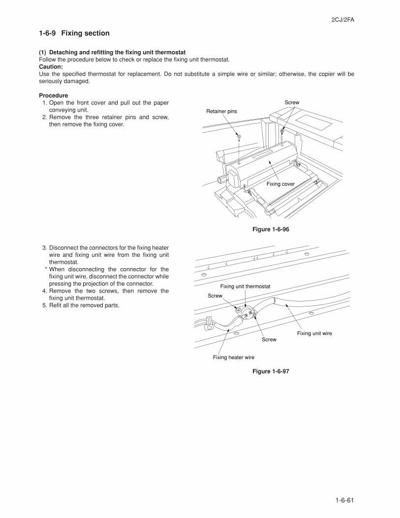
2CJ/2FA
1-6-61
1-6-9 Fixing section
(1) Detaching and refitting the fixing unit thermostatFollow the procedure below to check or replace the fixing unit thermostat.Caution:Use the specified thermostat for replacement. Do not substitute a simple wire or similar; otherwise, the copier will beseriously damaged.
Procedure1. Open the front cover and pull out the paper
conveying unit.2. Remove the three retainer pins and screw,
then remove the fixing cover.
Figure 1-6-96
3. Disconnect the connectors for the fixing heaterwire and fixing unit wire from the fixing unitthermostat.
* When disconnecting the connector for thefixing unit wire, disconnect the connector whilepressing the projection of the connector.
4. Remove the two screws, then remove thefixing unit thermostat.
5. Refit all the removed parts.
Figure 1-6-97
Screw
Retainer pins
Fixing cover
Fixing unit thermostat
Fixing unit wire
Fixing heater wire
Screw
Screw
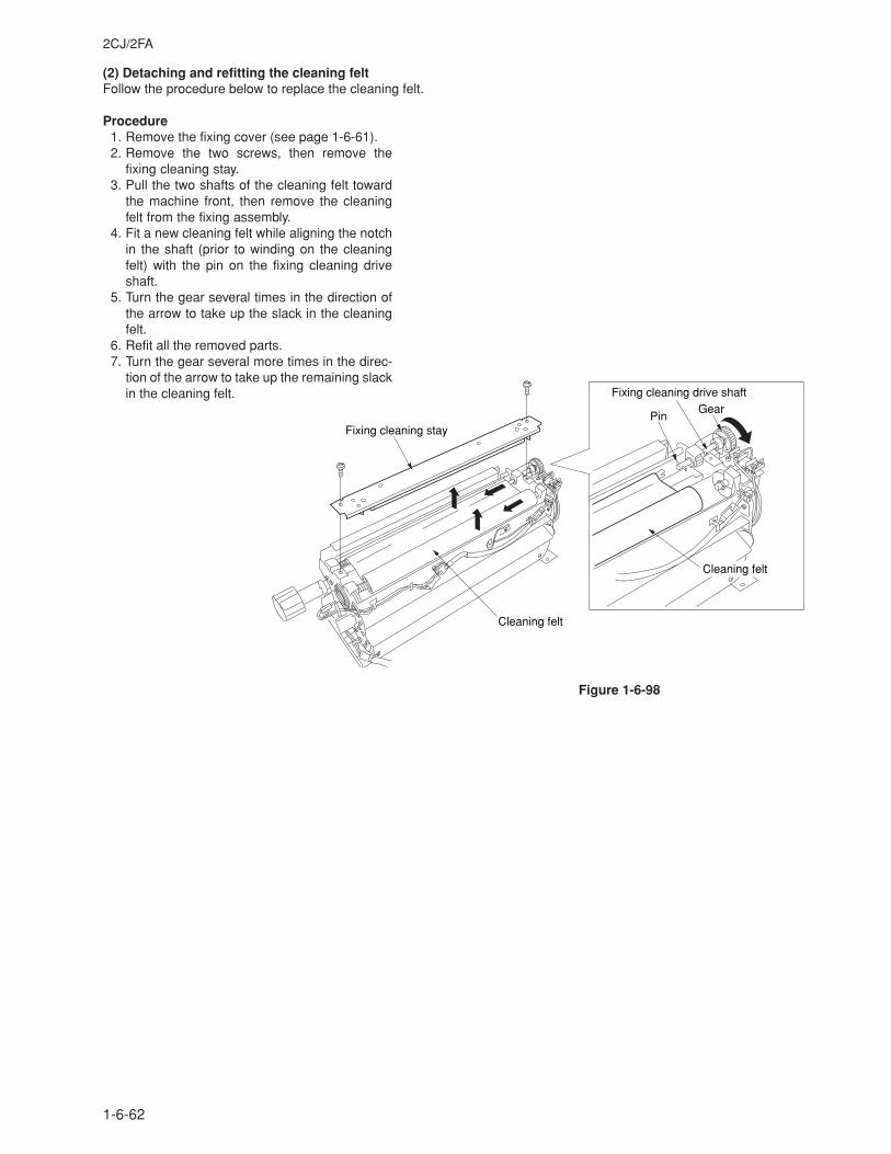
2CJ/2FA
1-6-62
(2) Detaching and refitting the cleaning feltFollow the procedure below to replace the cleaning felt.
Procedure1. Remove the fixing cover (see page 1-6-61).2. Remove the two screws, then remove the
fixing cleaning stay.3. Pull the two shafts of the cleaning felt toward
the machine front, then remove the cleaningfelt from the fixing assembly.
4. Fit a new cleaning felt while aligning the notchin the shaft (prior to winding on the cleaningfelt) with the pin on the fixing cleaning driveshaft.
5. Turn the gear several times in the direction ofthe arrow to take up the slack in the cleaningfelt.
6. Refit all the removed parts.7. Turn the gear several more times in the direc-
tion of the arrow to take up the remaining slackin the cleaning felt.
Figure 1-6-98
Fixing cleaning drive shaft
Fixing cleaning stay
Cleaning felt
PinGear
Cleaning felt
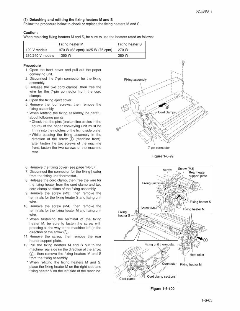
2CJ/2FA-1
1-6-63
(3) Detaching and refitting the fixing heaters M and SFollow the procedure below to check or replace the fixing heaters M and S.
Caution:When replacing fixing heaters M and S, be sure to use the heaters rated as follows:
Fixing heater M Fixing heater S
120 V models 970 W (63 cpm)/1025 W (75 cpm) 270 W
230/240 V models 1350 W 380 W
Procedure1. Open the front cover and pull out the paper
conveying unit.2. Disconnect the 7-pin connector for the fixing
assembly.3. Release the two cord clamps, then free the
wire for the 7-pin connector from the cordclamps.
4. Open the fixing eject cover.5. Remove the four screws, then remove the
fixing assembly.* When refitting the fixing assembly, be careful
about following points.• Check that the pins (broken line circles in the
figure) of the paper conveying unit must befirmly into the notches of the fixing side plate.
• While passing the fixing assembly in thedirection of the arrow a (machine front),after fasten the two screws of the machinefront, fasten the two screws of the machinerear.
Figure 1-6-99
6. Remove the fixing cover (see page 1-6-57).7. Disconnect the connector for the fixing heater
from the fixing unit thermostat.8. Release the cord clamp, then free the wire for
the fixing heater from the cord clamp and twocord clamp sections of the fixing assembly.
9. Remove the screw (M3), then remove theterminals for the fixing heater S and fixing unitwire.
10. Remove the screw (M4), then remove theterminals for the fixing heater M and fixing unitwire.
* When fastening the terminal of the fixingheater M, be sure to fasten the screw withpressing all the way to the machine left (in thedirection of the arrow b).
11. Remove the screw, then remove the rearheater support plate.
12. Pull the fixing heaters M and S out to themachine rear side (in the direction of the arrowa), then remove the fixing heaters M and Sfrom the fixing assembly.
* When refitting the fixing heaters M and S,place the fixing heater M on the right side andfixing heater S on the left side of the machine.
Figure 1-6-100
Cord clamps
7-pin connector
Fixing assembly
a
Fixing heater M
Fixing heater S
Heat roller
a
Fixing heater S
Rear heater support plate
Screw (M3)
Fixing heater MScrew (M4)
Screw
b
Fixing unit wires
Cord clamp
Connector
Fixing unit thermostat
Cord clamp sections
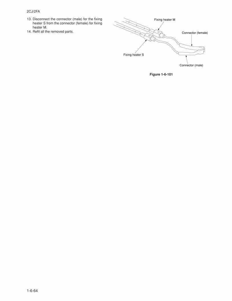
2CJ/2FA
1-6-64
13. Disconnect the connector (male) for the fixingheater S from the connector (female) for fixingheater M.
14. Refit all the removed parts.
Figure 1-6-101
Fixing heater M
Fixing heater S
Connector (female)
Connector (male)
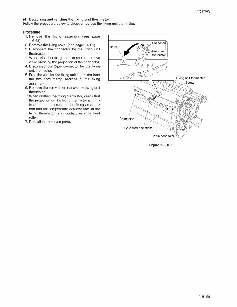
2CJ/2FA
1-6-65
(4) Detaching and refitting the fixing unit thermistorFollow the procedure below to check or replace the fixing unit thermistor.
Procedure1. Remove the fixing assembly (see page
1-6-63).2. Remove the fixing cover (see page 1-6-61).3. Disconnect the connector for the fixing unit
thermostat.* When disconnecting the connector, remove
while pressing the projection of the connector.4. Disconnect the 2-pin connector for the fixing
unit thermistor.5. Free the wire for the fixing unit thermistor from
the two cord clamp sections of the fixingassembly.
6. Remove the screw, then remove the fixing unitthermistor.
* When refitting the fixing thermistor, check thatthe projection on the fixing thermistor is firmlyinserted into the notch in the fixing assemblyand that the temperature detector face of thefixing thermistor is in contact with the heatroller.
7. Refit all the removed parts.
Figure 1-6-102
Screw
Fixing unit thermistor
Cord clamp sections
NotchFixing unit thermistor
Connector
2-pin connector
Projection
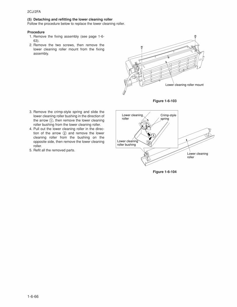
2CJ/2FA
1-6-66
(5) Detaching and refitting the lower cleaning rollerFollow the procedure below to replace the lower cleaning roller.
Procedure1. Remove the fixing assembly (see page 1-6-
63).2. Remove the two screws, then remove the
lower cleaning roller mount from the fixingassembly.
Figure 1-6-103
3. Remove the crimp-style spring and slide thelower cleaning roller bushing in the direction ofthe arrow 1, then remove the lower cleaningroller bushing from the lower cleaning roller.
4. Pull out the lower cleaning roller in the direc-tion of the arrow 2 and remove the lowercleaning roller from the bushing on theopposite side, then remove the lower cleaningroller.
5. Refit all the removed parts.
Figure 1-6-104
Lower cleaning roller mount
Lower cleaning roller
Crimp-style spring
Lower cleaning roller
Lower cleaning roller bushing
1
2
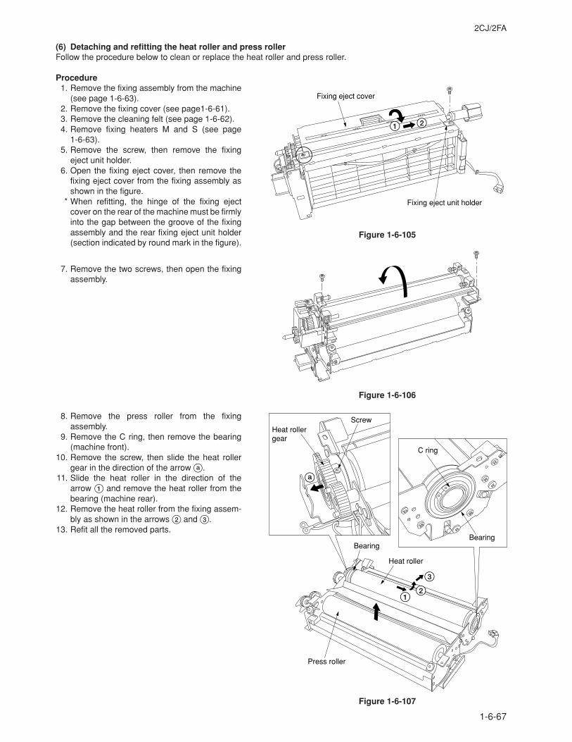
2CJ/2FA
1-6-67
(6) Detaching and refitting the heat roller and press rollerFollow the procedure below to clean or replace the heat roller and press roller.
Procedure1. Remove the fixing assembly from the machine
(see page 1-6-63).2. Remove the fixing cover (see page1-6-61).3. Remove the cleaning felt (see page 1-6-62).4. Remove fixing heaters M and S (see page
1-6-63).5. Remove the screw, then remove the fixing
eject unit holder.6. Open the fixing eject cover, then remove the
fixing eject cover from the fixing assembly asshown in the figure.
* When refitting, the hinge of the fixing ejectcover on the rear of the machine must be firmlyinto the gap between the groove of the fixingassembly and the rear fixing eject unit holder(section indicated by round mark in the figure).
7. Remove the two screws, then open the fixingassembly.
Figure 1-6-106
8. Remove the press roller from the fixingassembly.
9. Remove the C ring, then remove the bearing(machine front).
10. Remove the screw, then slide the heat rollergear in the direction of the arrow a.
11. Slide the heat roller in the direction of thearrow 1 and remove the heat roller from thebearing (machine rear).
12. Remove the heat roller from the fixing assem-bly as shown in the arrows 2 and 3.
13. Refit all the removed parts.
Figure 1-6-107
Fixing eject cover
Fixing eject unit holder
1 2
Bearing
Heat roller
Press roller
ScrewHeat roller gear
C ring
Bearing
1
3
2
a
Figure 1-6-105
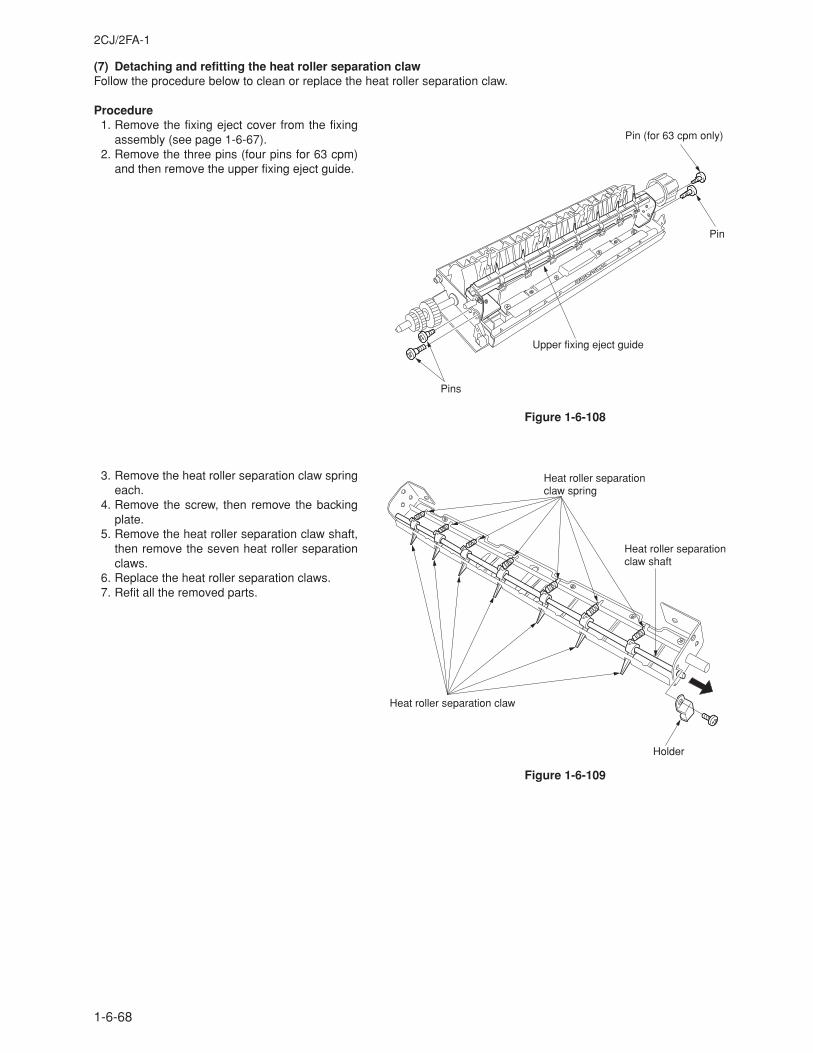
2CJ/2FA-1
1-6-68
(7) Detaching and refitting the heat roller separation clawFollow the procedure below to clean or replace the heat roller separation claw.
Procedure1. Remove the fixing eject cover from the fixing
assembly (see page 1-6-67).2. Remove the three pins (four pins for 63 cpm)
and then remove the upper fixing eject guide.
Figure 1-6-108
Figure 1-6-109
Upper fixing eject guide
Pins
Pin
Pin (for 63 cpm only)
Heat roller separation claw spring
Holder
Heat roller separation claw
Heat roller separation claw shaft
3. Remove the heat roller separation claw springeach.
4. Remove the screw, then remove the backingplate.
5. Remove the heat roller separation claw shaft,then remove the seven heat roller separationclaws.
6. Replace the heat roller separation claws.7. Refit all the removed parts.
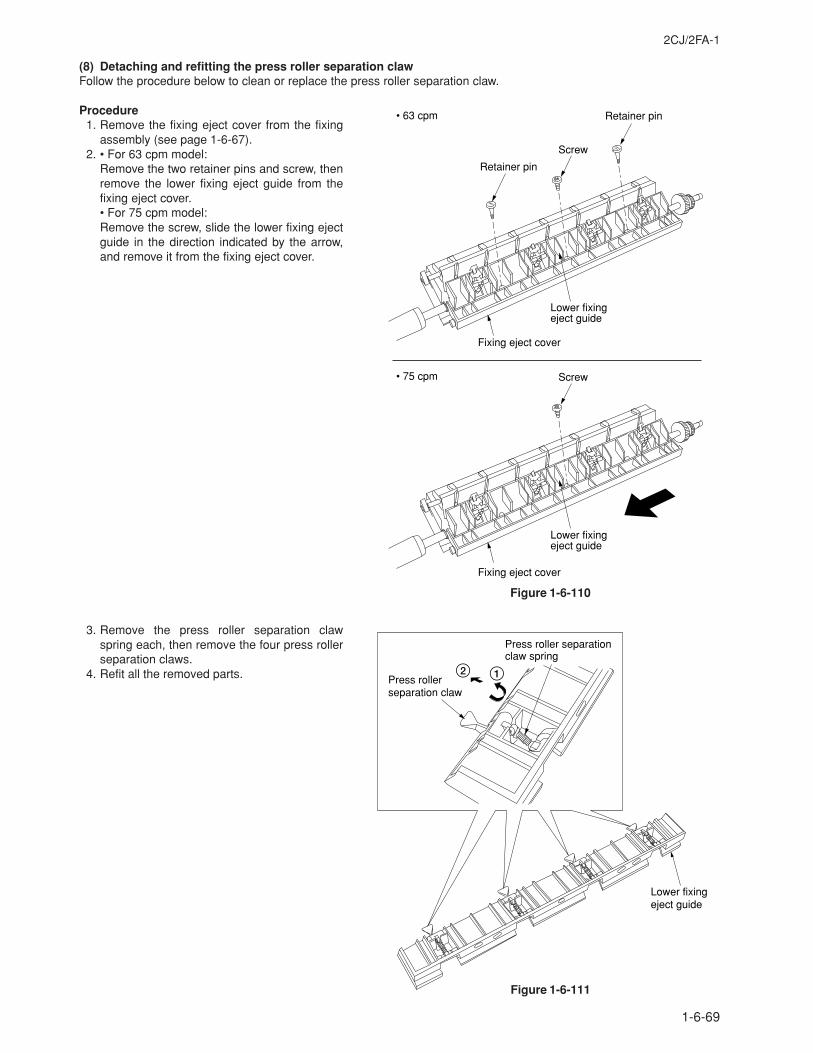
2CJ/2FA-1
1-6-69
(8) Detaching and refitting the press roller separation clawFollow the procedure below to clean or replace the press roller separation claw.
Procedure1. Remove the fixing eject cover from the fixing
assembly (see page 1-6-67).2. • For 63 cpm model:
Remove the two retainer pins and screw, thenremove the lower fixing eject guide from thefixing eject cover.• For 75 cpm model:Remove the screw, slide the lower fixing ejectguide in the direction indicated by the arrow,and remove it from the fixing eject cover.
Figure 1-6-110
3. Remove the press roller separation clawspring each, then remove the four press rollerseparation claws.
4. Refit all the removed parts.
Figure 1-6-111
Screw• 75 cpm
• 63 cpm
Lower fixing eject guide
Fixing eject cover
Screw
Retainer pin
Lower fixing eject guide
Retainer pin
Fixing eject cover
Press roller separation claw
Press roller separation claw spring
2 1
Lower fixing eject guide
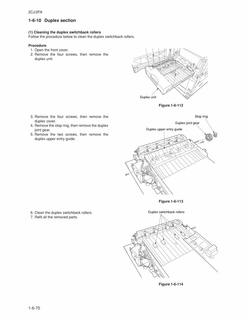
2CJ/2FA
1-6-70
1-6-10 Duplex section
(1) Cleaning the duplex switchback rollersFollow the procedure below to clean the duplex switchback rollers.
Procedure1. Open the front cover.2. Remove the four screws, then remove the
duplex unit.
Figure 1-6-112
3. Remove the four screws, then remove theduplex cover.
4. Remove the stop ring, then remove the duplexjoint gear.
5. Remove the two screws, then remove theduplex upper entry guide.
Figure 1-6-113
6. Clean the duplex switchback rollers.7. Refit all the removed parts.
Figure 1-6-114
Duplex unit
Duplex upper entry guide
Duplex joint gear
Stop ring
Duplex switchback rollers
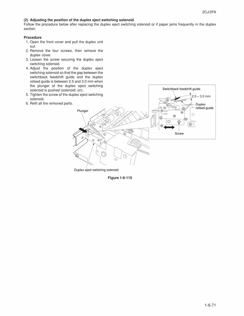
2CJ/2FA
1-6-71
(2) Adjusting the position of the duplex eject switching solenoidFollow the procedure below after replacing the duplex eject switching solenoid or if paper jams frequently in the duplexsection.
Procedure1. Open the front cover and pull the duplex unit
out.2. Remove the four screws, then remove the
duplex cover.3. Loosen the screw securing the duplex eject
switching solenoid.4. Adjust the position of the duplex eject
switching solenoid so that the gap between theswitchback feedshift guide and the duplexrefeed guide is between 2.5 and 3.0 mm whenthe plunger of the duplex eject switchingsolenoid is pushed (solenoid: on).
5. Tighten the screw of the duplex eject switchingsolenoid.
6. Refit all the removed parts.
Figure 1-6-115
Duplex eject switching solenoid
Plunger
Switchback feedshift guide
Duplex refeed guide
Screw
2.5 – 3.0 mm
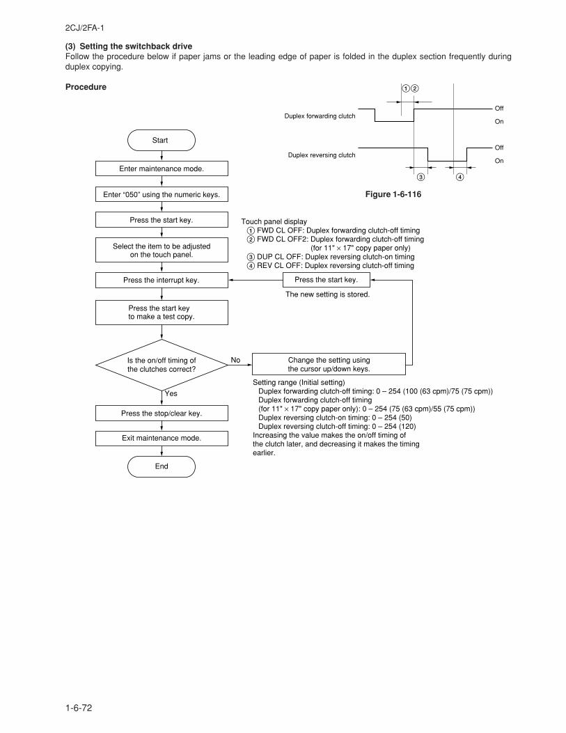
2CJ/2FA-1
1-6-72
(3) Setting the switchback driveFollow the procedure below if paper jams or the leading edge of paper is folded in the duplex section frequently duringduplex copying.
Procedure
Figure 1-6-116
Duplex forwarding clutchOff
On
Off
OnDuplex reversing clutch
12
3 4
End
Start
Enter maintenance mode.
Enter “050” using the numeric keys.
No
Yes
Press the start key.
Press the interrupt key.
Press the start key to make a test copy.
Press the stop/clear key.
Exit maintenance mode.
Setting range (Initial setting)Duplex forwarding clutch-off timing: 0 – 254 (100 (63 cpm)/75 (75 cpm))Duplex forwarding clutch-off timing (for 11" × 17" copy paper only): 0 – 254 (75 (63 cpm)/55 (75 cpm))Duplex reversing clutch-on timing: 0 – 254 (50)Duplex reversing clutch-off timing: 0 – 254 (120)
Increasing the value makes the on/off timing of the clutch later, and decreasing it makes the timing earlier.
The new setting is stored.
Select the item to be adjusted on the touch panel.
Touch panel display1 FWD CL OFF: Duplex forwarding clutch-off timing2 FWD CL OFF2: Duplex forwarding clutch-off timing
(for 11" × 17" copy paper only)3 DUP CL OFF: Duplex reversing clutch-on timing4 REV CL OFF: Duplex reversing clutch-off timing
Is the on/off timing of the clutches correct?
Change the setting using the cursor up/down keys.
Press the start key.
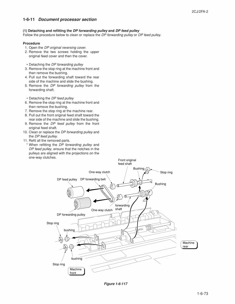
2CJ/2FA-2
1-6-73
1-6-11 Document processor section
(1) Detaching and refitting the DP forwarding pulley and DP feed pulleyFollow the procedure below to clean or replace the DP forwarding pulley or DP feed pulley.
Procedure1. Open the DP original reversing cover.2. Remove the two screws holding the upper
original feed cover and then the cover.
• Detaching the DP forwarding pulley3. Remove the stop ring at the machine front and
then remove the bushing.4. Pull out the forwarding shaft toward the rear
side of the machine and slide the bushing.5. Remove the DP forwarding pulley from the
forwarding shaft.
• Detaching the DP feed pulley6. Remove the stop ring at the machine front and
then remove the bushing.7. Remove the stop ring at the machine rear.8. Pull out the front original feed shaft toward the
rear side of the machine and slide the bushing.9. Remove the DP feed pulley from the front
original feed shaft.10. Clean or replace the DP forwarding pulley and
the DP feed pulley.11. Refit all the removed parts.
* When refitting the DP forwarding pulley andDP feed pulley, ensure that the notches in thepulleys are aligned with the projections on theone-way clutches.
Figure 1-6-117
Front originalfeed shaft
Bushing
Bushing
DP feed pulley
forwardingshaft
DP forwarding belt
DP forwarding pulley
bushing
bushing
Stop ring
Stop ring
One-way clutch
One-way clutch
Stop ring
Machinefront
Machinerear
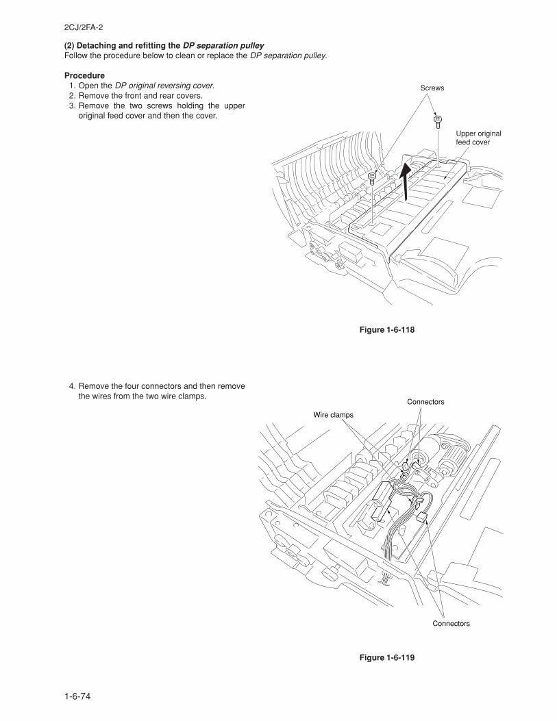
2CJ/2FA-2
1-6-74
(2) Detaching and refitting the DP separation pulleyFollow the procedure below to clean or replace the DP separation pulley.
Procedure1. Open the DP original reversing cover.2. Remove the front and rear covers.3. Remove the two screws holding the upper
original feed cover and then the cover.
4. Remove the four connectors and then removethe wires from the two wire clamps.
Upper originalfeed cover
Screws
Figure 1-6-118
Wire clamps
Connectors
Connectors
Figure 1-6-119
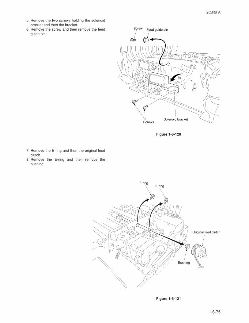
2CJ/2FA
1-6-75
5. Remove the two screws holding the solenoidbracket and then the bracket.
6. Remove the screw and then remove the feedguide pin.
7. Remove the E-ring and then the original feedclutch.
8. Remove the E-ring and then remove thebushing.
Screws
Screw Feed guide pin
Solenoid bracket
Figure 1-6-120
E-ringE-ring
Original feed clutch
Bushing
Figure 1-6-121
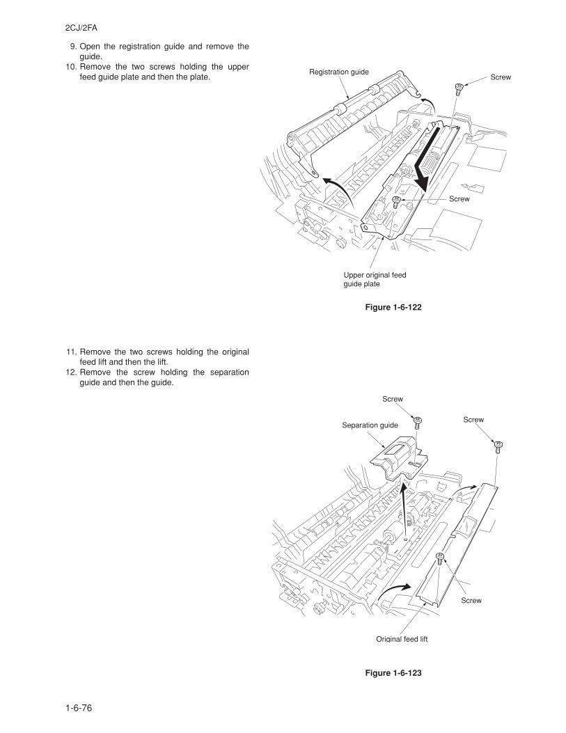
2CJ/2FA
1-6-76
9. Open the registration guide and remove theguide.
10. Remove the two screws holding the upperfeed guide plate and then the plate.
11. Remove the two screws holding the originalfeed lift and then the lift.
12. Remove the screw holding the separationguide and then the guide.
Screw
ScrewRegistration guide
Upper original feedguide plate
Figure 1-6-122
Screw
Separation guideScrew
Screw
Original feed lift
Figure 1-6-123
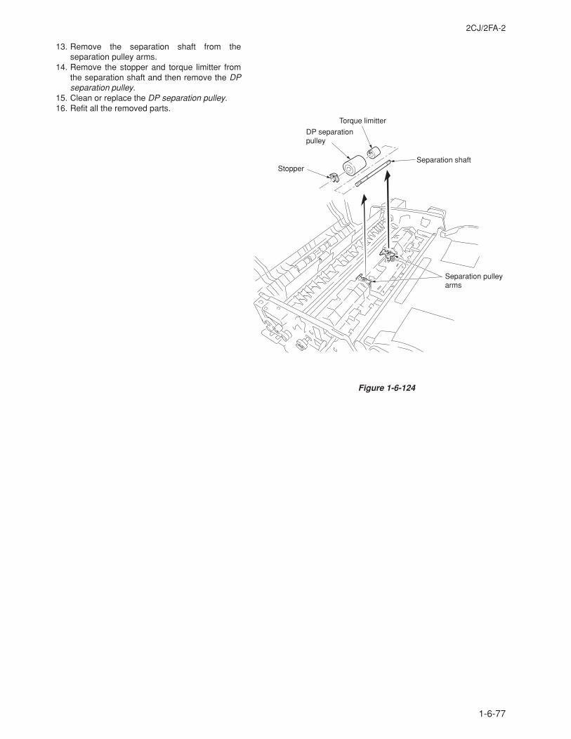
2CJ/2FA-2
1-6-77
13. Remove the separation shaft from theseparation pulley arms.
14. Remove the stopper and torque limitter fromthe separation shaft and then remove the DPseparation pulley.
15. Clean or replace the DP separation pulley.16. Refit all the removed parts.
DP separationpulley
Separation pulleyarms
StopperSeparation shaft
Torque limitter
Figure 1-6-124
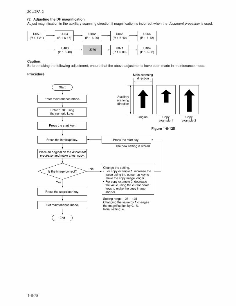
2CJ/2FA-2
1-6-78
(3) Adjusting the DF magnificationAdjust magnification in the auxiliary scanning direction if magnification is incorrect when the document processor is used.
U053(P. 1-4-21)
U403(P. 1-6-43)
U402(P. 1-6-20)
U066(P. 1-6-42)
U070 U071(P. 1-6-80)
U404(P. 1-6-82)
U065(P. 1-6-40)
U034(P. 1-6-17)
Caution:Before making the following adjustment, ensure that the above adjustments have been made in maintenance mode.
Procedure
Auxiliary scanning direction
Original
Main scanning direction
Copy example 1
Copy example 2
Enter maintenance mode.
Place an original on the document processor and make a test copy.
Yes
No
Start
End
Exit maintenance mode.
Press the stop/clear key.
Is the image correct?
Enter “070” using the numeric keys.
Press the interrupt key.
Setting range: –25 – +25Changing the value by 1 changes the magnification by 0.1%.Initial setting: 4
Change the setting.• For copy example 1, increase the
value using the cursor up key to make the copy image longer.
• For copy example 2, decrease the value using the cursor down keys to make the copy image shorter.
Press the start key.
Press the start key.
The new setting is stored.
Figure 1-6-125
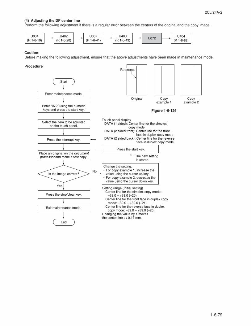
2CJ/2FA-2
1-6-79
(4) Adjusting the DF center linePerform the following adjustment if there is a regular error between the centers of the original and the copy image.
U034(P. 1-6-19)
U404(P. 1-6-82)
U067(P. 1-6-41)
U072U403
(P. 1-6-43)U402
(P. 1-6-20)
Caution:Before making the following adjustment, ensure that the above adjustments have been made in maintenance mode.
Procedure
Original Copy example 1
Copy example 2
Reference
Enter maintenance mode.
Place an original on the document processor and make a test copy.
Yes
No
Start
End
Change the setting.• For copy example 1, increase the
value using the cursor up key.• For copy example 2, decrease the
value using the cursor down key.
Exit maintenance mode.
Press the stop/clear key.
Is the image correct?
Enter “072” using the numeric keys and press the start key.
Press the interrupt key.
Select the item to be adjusted on the touch panel.
Press the start key.
The new setting is stored.
Touch panel displayDATA (1 sided): Center line for the simplex
copy modeDATA (2 sided front): Center line for the front
face in duplex copy modeDATA (2 sided back): Center line for the reverse
face in duplex copy mode
Setting range (Initial setting)Center line for the simplex copy mode:
–39.0 – +39.0 (–25)Center line for the front face in duplex copy
mode: –39.0 – +39.0 (–21)Center line for the reverse face in duplex
copy mode: –39.0 – +39.0 (–20)Changing the value by 1 moves the center line by 0.17 mm.
Figure 1-6-126
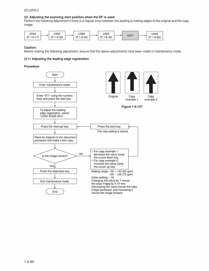
2CJ/2FA-2
1-6-80
(5) Adjusting the scanning start position when the DF is usedPerform the following adjustment if there is a regular error between the leading or trailing edges of the original and the copyimage.
U034(P. 1-6-17)
U404(P. 1-6-82)
U066(P. 1-6-42)
U071U403
(P. 1-6-43)U402
(P. 1-6-20)
Caution:Before making the following adjustment, ensure that the above adjustments have been made in maintenance mode.
(5-1) Adjusting the leading edge registration
Procedure
Enter maintenance mode.
Enter “071” using the numeric keys and press the start key.
Yes
No
Start
End
• For copy example 1, decrease the value using the cursor down key.
• For copy example 2, increase the value using the cursor up key.
Press the interrupt key.
Exit maintenance mode.
Press the stop/clear key.
Place an original on the document processor and make a test copy.
Is the image correct?
Setting range: –32 – +32 (63 cpm) –29 – +29 (75 cpm)Initial settting: –19Changing the value by 1 moves the copy image by 0.19 mm.Decreasing the value moves the copy image backward, and increasing it moves the image forward.
Press the start key.
The new setting is stored.
To adjust the leading edge registration, select “LEAD EDGE ADJ.”
Original Copy example 1
Copy example 2
Figure 1-6-127
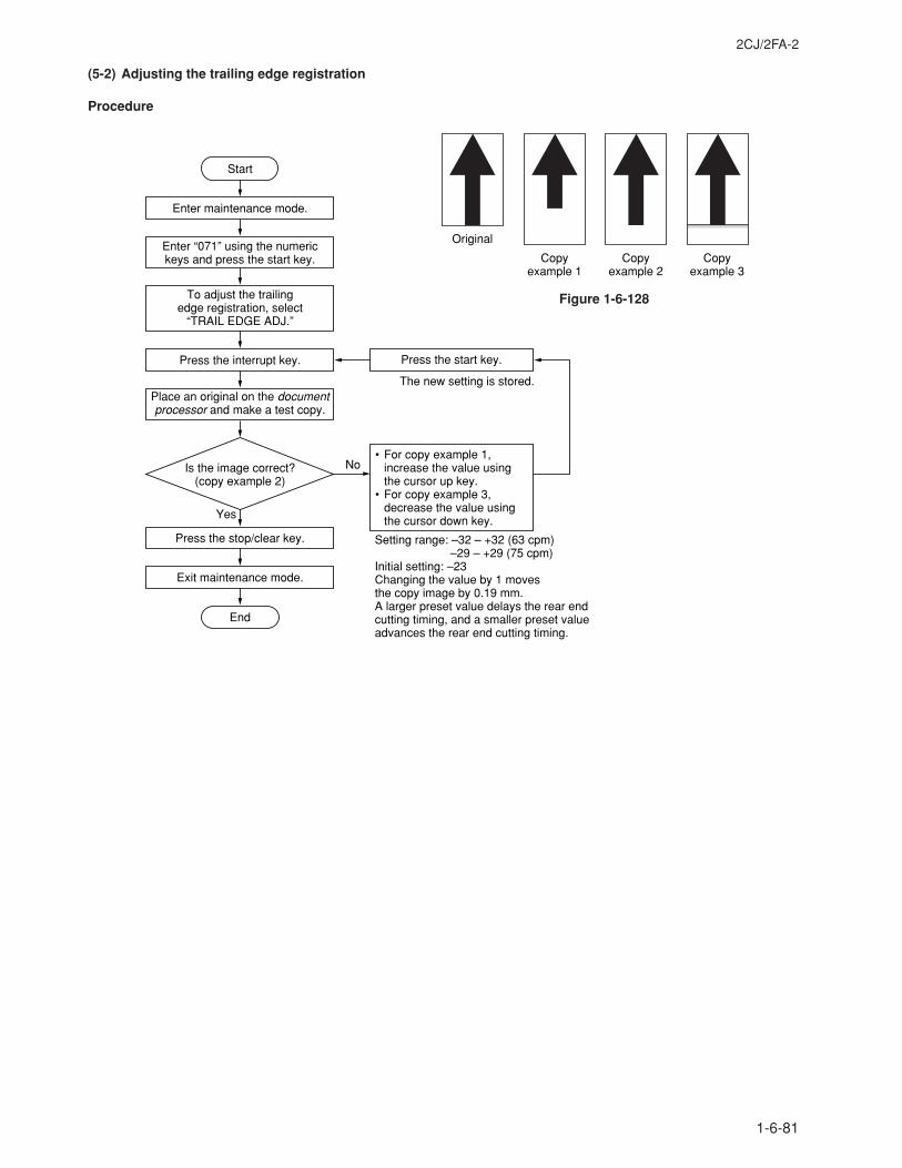
2CJ/2FA-2
1-6-81
(5-2) Adjusting the trailing edge registration
Procedure
Figure 1-6-128
Enter maintenance mode.
Enter “071” using the numeric keys and press the start key.
Yes
No
Start
End
• For copy example 1, increase the value using the cursor up key.
• For copy example 3, decrease the value using the cursor down key.
Press the interrupt key.
Exit maintenance mode.
Press the stop/clear key.
Place an original on the document processor and make a test copy.
Is the image correct?(copy example 2)
Setting range: –32 – +32 (63 cpm) –29 – +29 (75 cpm)Initial setting: –23Changing the value by 1 moves the copy image by 0.19 mm.A larger preset value delays the rear end cutting timing, and a smaller preset value advances the rear end cutting timing.
Press the start key.
The new setting is stored.
To adjust the trailing edge registration, select
“TRAIL EDGE ADJ.”
Copy example 1
Original
Copy example 2
Copy example 3
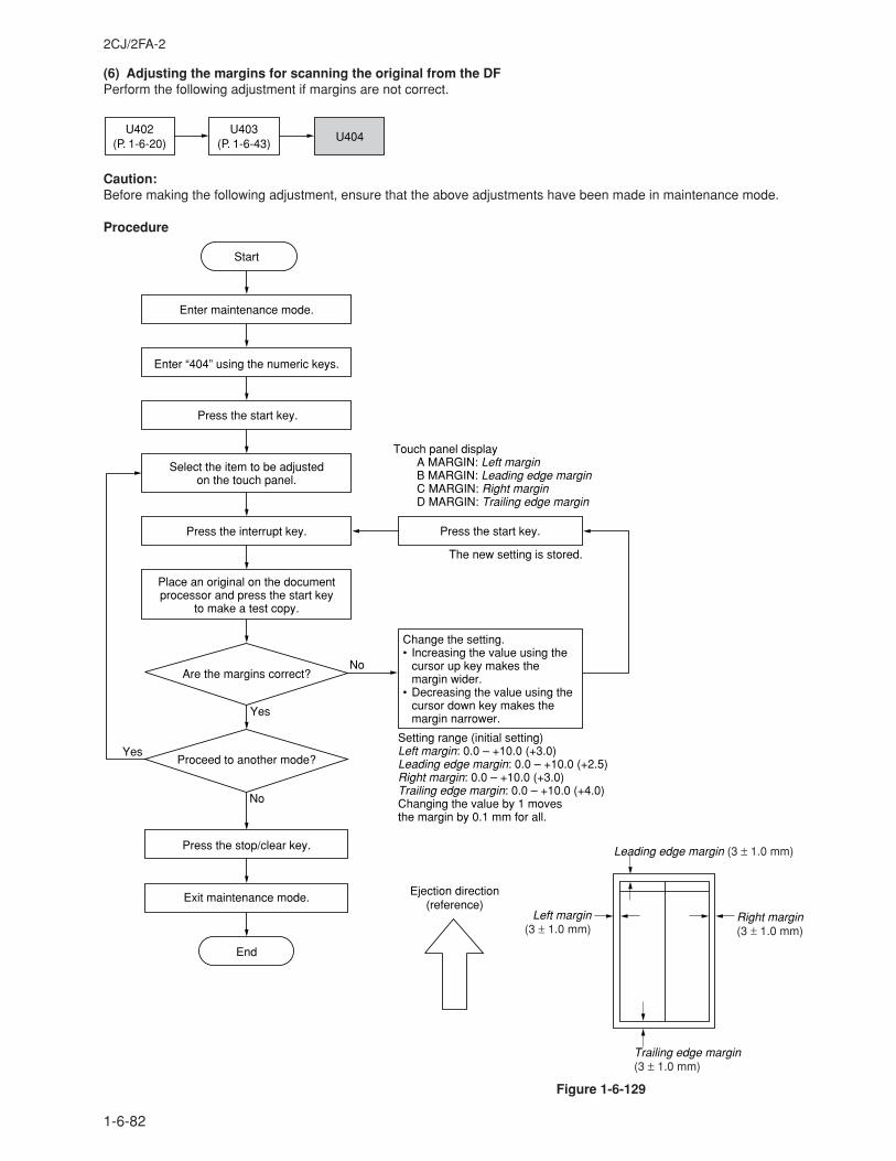
2CJ/2FA-2
1-6-82
(6) Adjusting the margins for scanning the original from the DFPerform the following adjustment if margins are not correct.
U402(P. 1-6-20)
U404U403
(P. 1-6-43)
Caution:Before making the following adjustment, ensure that the above adjustments have been made in maintenance mode.
Procedure
Figure 1-6-129
Change the setting.• Increasing the value using the
cursor up key makes the margin wider.
• Decreasing the value using the cursor down key makes the margin narrower.
Touch panel displayA MARGIN: Left marginB MARGIN: Leading edge marginC MARGIN: Right marginD MARGIN: Trailing edge margin
Yes
No
Start
Enter maintenance mode.
Enter “404” using the numeric keys.
Press the start key.
Place an original on the documentprocessor and press the start key
to make a test copy.
Press the start key.
The new setting is stored.
Setting range (initial setting)Left margin: 0.0 – +10.0 (+3.0)Leading edge margin: 0.0 – +10.0 (+2.5)Right margin: 0.0 – +10.0 (+3.0)Trailing edge margin: 0.0 – +10.0 (+4.0)Changing the value by 1 moves the margin by 0.1 mm for all.
Select the item to be adjusted on the touch panel.
Are the margins correct?
Press the interrupt key.
Yes
No
Proceed to another mode?
Press the stop/clear key.
Exit maintenance mode.
End
Leading edge margin (3 ± 1.0 mm)
Left margin(3 ± 1.0 mm)
Right margin(3 ± 1.0 mm)
Ejection direction(reference)
Trailing edge margin(3 ± 1.0 mm)
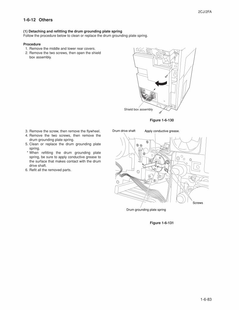
2CJ/2FA
1-6-83
1-6-12 Others
(1) Detaching and refitting the drum grounding plate springFollow the procedure below to clean or replace the drum grounding plate spring.
Procedure1. Remove the middle and lower rear covers.2. Remove the two screws, then open the shield
box assembly.
Figure 1-6-130
3. Remove the screw, then remove the flywheel.4. Remove the two screws, then remove the
drum grounding plate spring.5. Clean or replace the drum grounding plate
spring.* When refitting the drum grounding plate
spring, be sure to apply conductive grease tothe surface that makes contact with the drumdrive shaft.
6. Refit all the removed parts.
Figure 1-6-131
Shield box assembly
Apply conductive grease.Drum drive shaft
Screws
Drum grounding plate spring
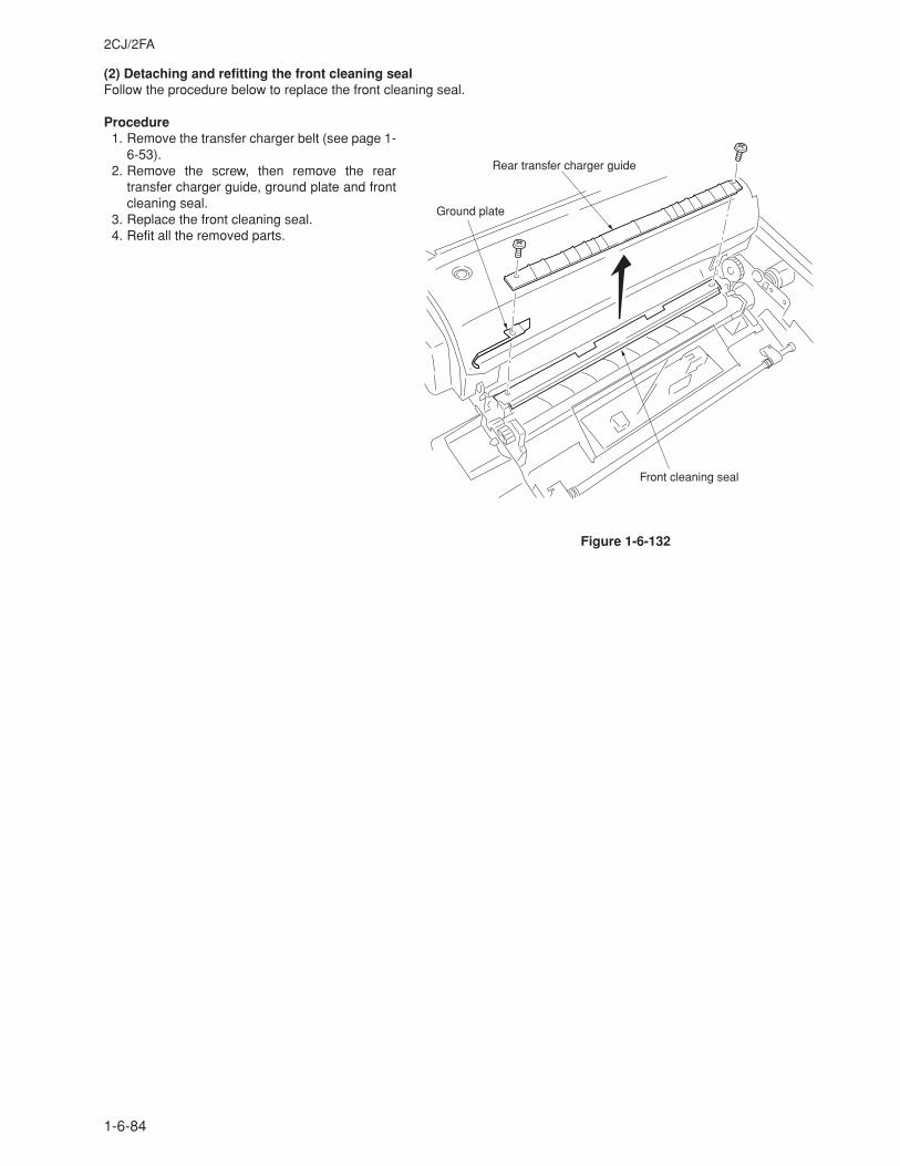
2CJ/2FA
1-6-84
(2) Detaching and refitting the front cleaning sealFollow the procedure below to replace the front cleaning seal.
Procedure1. Remove the transfer charger belt (see page 1-
6-53).2. Remove the screw, then remove the rear
transfer charger guide, ground plate and frontcleaning seal.
3. Replace the front cleaning seal.4. Refit all the removed parts.
Figure 1-6-132
Ground plate
Rear transfer charger guide
Front cleaning seal
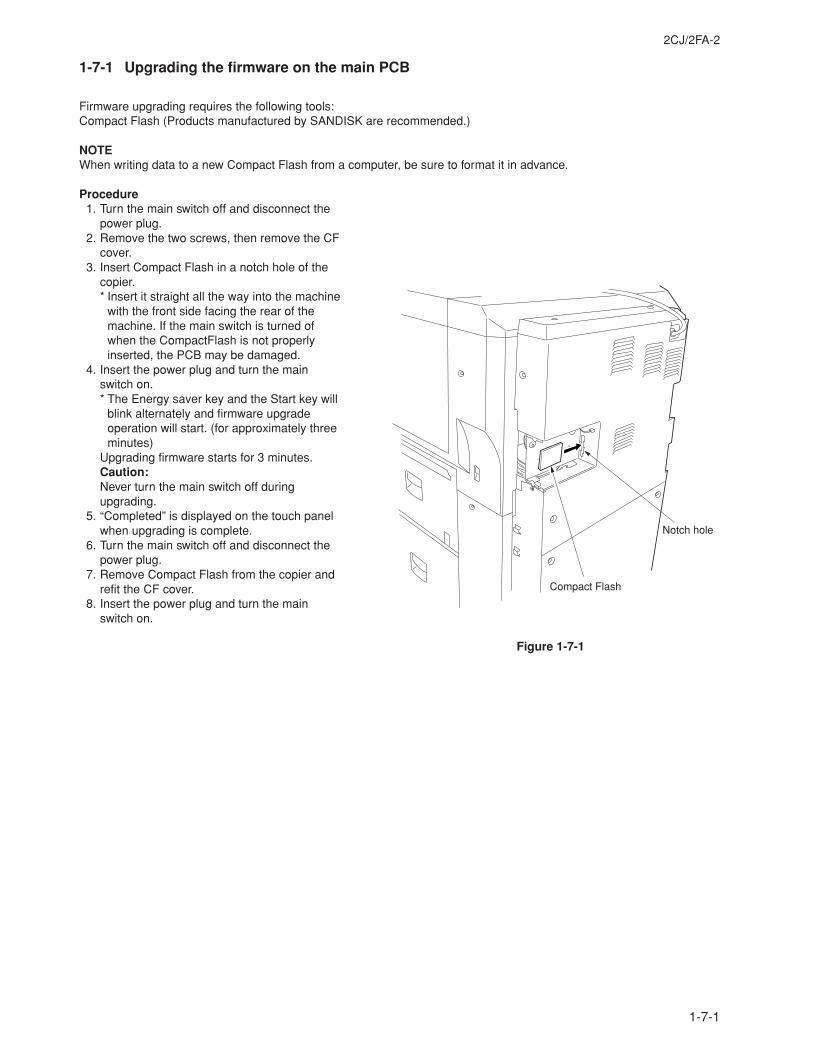
2CJ/2FA-2
1-7-1
Figure 1-7-1
1-7-1 Upgrading the firmware on the main PCB
Firmware upgrading requires the following tools:Compact Flash (Products manufactured by SANDISK are recommended.)
NOTEWhen writing data to a new Compact Flash from a computer, be sure to format it in advance.
Procedure1. Turn the main switch off and disconnect the
power plug.2. Remove the two screws, then remove the CF
cover.3. Insert Compact Flash in a notch hole of the
copier.* Insert it straight all the way into the machine
with the front side facing the rear of themachine. If the main switch is turned ofwhen the CompactFlash is not properlyinserted, the PCB may be damaged.
4. Insert the power plug and turn the mainswitch on.* The Energy saver key and the Start key will
blink alternately and firmware upgradeoperation will start. (for approximately threeminutes)
Upgrading firmware starts for 3 minutes.Caution:Never turn the main switch off duringupgrading.
5. “Completed” is displayed on the touch panelwhen upgrading is complete.
6. Turn the main switch off and disconnect thepower plug.
7. Remove Compact Flash from the copier andrefit the CF cover.
8. Insert the power plug and turn the mainswitch on.
Notch hole
Compact Flash
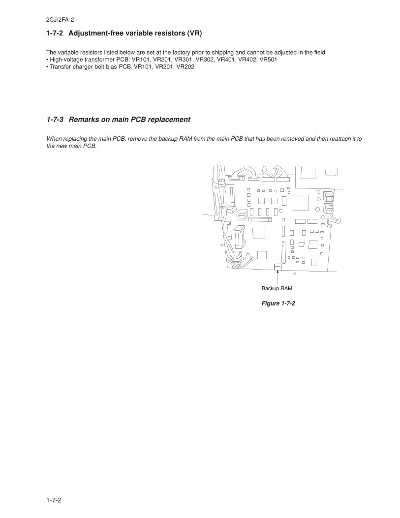
2CJ/2FA-2
1-7-2
1-7-2 Adjustment-free variable resistors (VR)
The variable resistors listed below are set at the factory prior to shipping and cannot be adjusted in the field.• High-voltage transformer PCB: VR101, VR201, VR301, VR302, VR401, VR402, VR501• Transfer charger belt bias PCB: VR101, VR201, VR202
1-7-3 Remarks on main PCB replacement
When replacing the main PCB, remove the backup RAM from the main PCB that has been removed and then reattach it tothe new main PCB.
Backup RAM
Figure 1-7-2
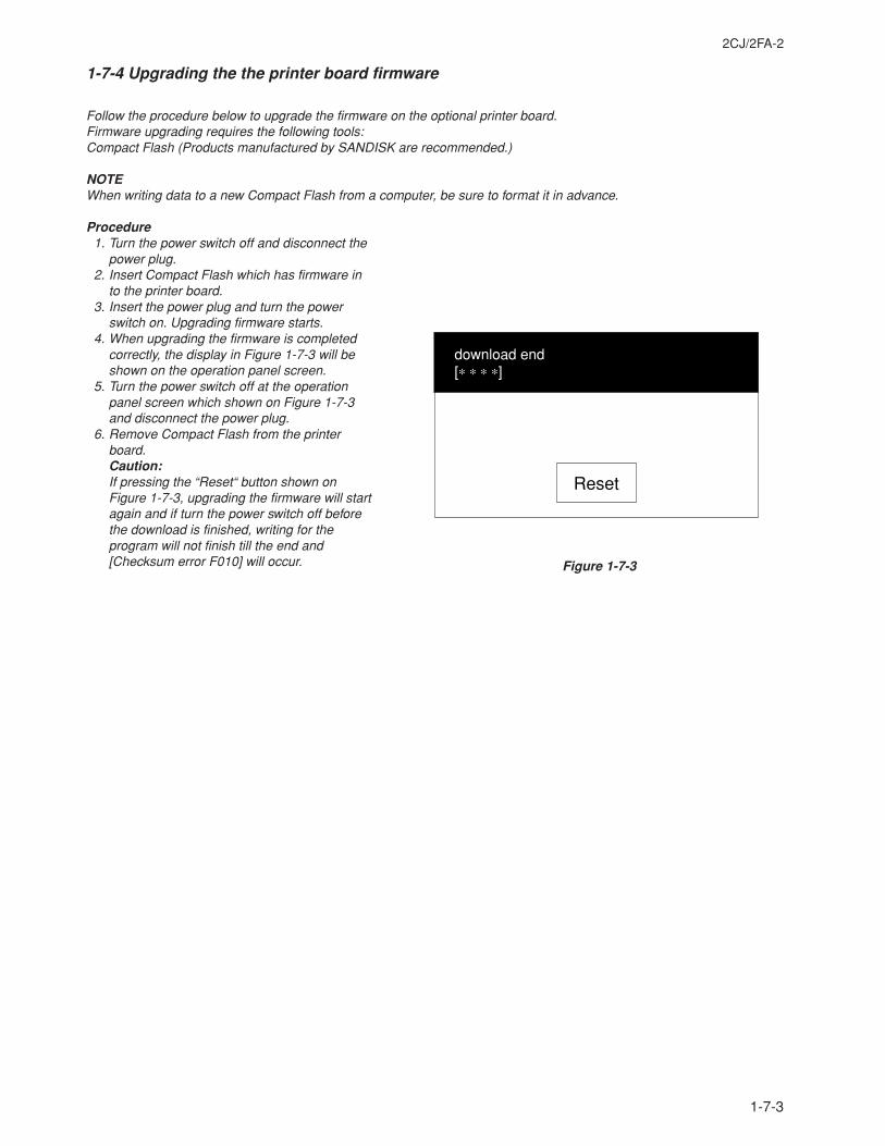
2CJ/2FA-2
1-7-3
1-7-4 Upgrading the the printer board firmware
Follow the procedure below to upgrade the firmware on the optional printer board.Firmware upgrading requires the following tools:Compact Flash (Products manufactured by SANDISK are recommended.)
NOTEWhen writing data to a new Compact Flash from a computer, be sure to format it in advance.
Procedure1. Turn the power switch off and disconnect the
power plug.2. Insert Compact Flash which has firmware in
to the printer board.3. Insert the power plug and turn the power
switch on. Upgrading firmware starts.4. When upgrading the firmware is completed
correctly, the display in Figure 1-7-3 will beshown on the operation panel screen.
5. Turn the power switch off at the operationpanel screen which shown on Figure 1-7-3and disconnect the power plug.
6. Remove Compact Flash from the printerboard.Caution:If pressing the “Reset“ button shown onFigure 1-7-3, upgrading the firmware will startagain and if turn the power switch off beforethe download is finished, writing for theprogram will not finish till the end and[Checksum error F010] will occur.
download end[∗ ∗ ∗ ∗]
Reset
Figure 1-7-3
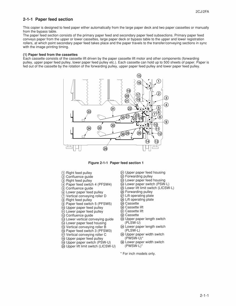
2CJ/2FA
2-1-1
2-1-1 Paper feed section
This copier is designed to feed paper either automatically from the large paper deck and two paper cassettes or manuallyfrom the bypass table.The paper feed section consists of the primary paper feed and secondary paper feed subsections. Primary paper feedconveys paper from the upper or lower cassettes, large paper deck or bypass table to the upper and lower registrationrollers, at which point secondary paper feed takes place and the paper travels to the transfer/conveying sections in syncwith the image printing timing.
(1) Paper feed from the cassettesEach cassette consists of the cassette lift driven by the paper cassette lift motor and other components (forwardingpulley, upper paper feed pulley, lower paper feed pulley etc.). Each cassette can hold up to 500 sheets of paper. Paper isfed out of the cassette by the rotation of the forwarding pulley, upper paper feed pulley and lower paper feed pulley.
´
‰ „
·
‚
Œ
ˇ
Á°
‡
$ #
@!0
98
765
4
32
1^
&*⁄
)(
¤
‹›fi
fl
%
Figure 2-1-1 Paper feed section 1
1 Right feed pulley2 Confluence guide3 Right feed pulley4 Paper feed switch 4 (PFSW4)5 Confluence guide6 Lower paper feed pulley7 Vertical conveying roller D8 Right feed pulley9 Paper feed switch 5 (PFSW5)0 Upper paper feed pulley! Lower paper feed pulley@ Confluence guide# Lower vertical conveying guide$ Lower paper feed housing% Vertical conveying roller B^ Paper feed switch 3 (PFSW3)& Vertical conveying roller C* Upper paper feed pulley( Upper paper switch (PSW-U)) Upper lift limit switch (LICSW-U)
⁄ Upper paper feed housing¤ Forwarding pulley‹ Lower paper feed housing› Lower paper switch (PSW-L)fi Lower lift limit switch (LICSW-L)fl Forwarding pulley‡ Lift operating plate° Lift operating plate· Cassette‚ Cassette liftŒ Cassette lift„ Cassette´ Upper paper length switch
(PLSW-U)‰ Lower paper length switch
(PLSW-L)ˇ Upper paper width switch
(PWSW-U)*Á Lower paper width switch
(PWSW-L)*
* For inch models only.
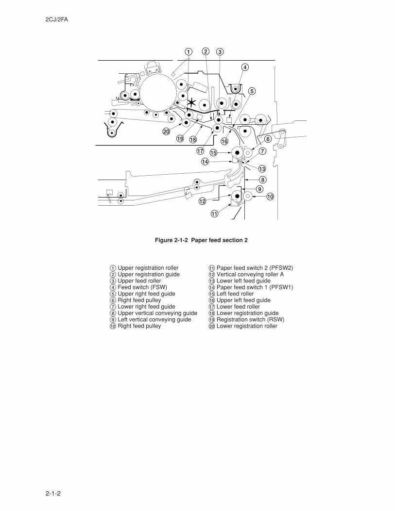
2CJ/2FA
2-1-2
1 2 3
4
5
6
7
$#
89
0
!
@
%
^&
*()
Figure 2-1-2 Paper feed section 2
1 Upper registration roller2 Upper registration guide3 Upper feed roller4 Feed switch (FSW)5 Upper right feed guide6 Right feed pulley7 Lower right feed guide8 Upper vertical conveying guide9 Left vertical conveying guide0 Right feed pulley
! Paper feed switch 2 (PFSW2)@ Vertical conveying roller A# Lower left feed guide$ Paper feed switch 1 (PFSW1)% Left feed roller^ Upper left feed guide& Lower feed roller* Lower registration guide( Registration switch (RSW)) Lower registration roller
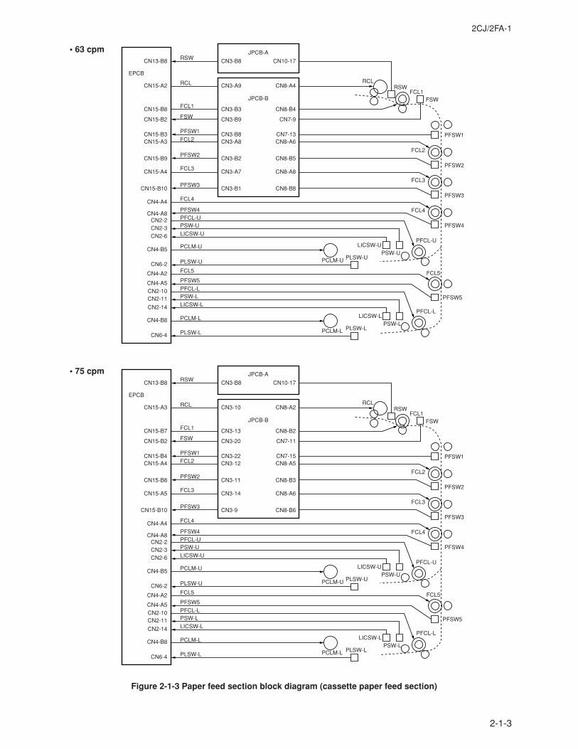
2CJ/2FA-1
2-1-3
EPCBRCLRCL
RSW
RSW
FCL1
FCL1
FCL2
FCL2
FCL5FCL5
PFSW1PFSW1
PFSW2
PFSW2
FSW
FSW
PFCL-L
PFCL-L
PSW-L
PSW-L PFSW5
PFSW5
LICSW-L
LICSW-L
PLSW-LPLSW-L PCLM-L
PCLM-L
CN13-B8
CN15-A2
CN15-B2
CN15-B3CN15-A3
CN15-B8
CN4-A5CN2-10CN2-11
CN2-14
CN6-4
CN4-B8
CN4-A2
FCL3
FCL3CN15-A4
FCL4
FCL4CN4-A4
PFCL-U
PFCL-U
PSW-U
PSW-U
LICSW-U
LICSW-U
PCLM-U
PCLM-U
CN2-2CN2-3CN2-6
CN4-B5PLSW-U
PLSW-UCN6-2
PFSW4
PFSW4CN4-A8
CN15-B9
PFSW3
PFSW3CN15-B10
CN10-17
CN8-A4
CN7-9
CN7-13CN8-A6
CN8-B4
CN8-A8
CN8-B5
CN8-B8
CN3-B8
CN3-A9
CN3-B9
CN3-B8CN3-A8
CN3-B3
CN3-A7
CN3-B2
CN3-B1
JPCB-A
JPCB-B
EPCBRCLRCL
RSW
RSW
FCL1
FCL1
FCL2
FCL2
FCL5FCL5
PFSW1PFSW1
PFSW2
PFSW2
FSW
FSW
PFCL-L
PFCL-L
PSW-L
PSW-L PFSW5
PFSW5
LICSW-L
LICSW-L
PLSW-LPLSW-L PCLM-L
PCLM-L
CN13-B8
CN15-A3
CN15-B2
CN15-B4CN15-A4
CN15-B7
CN4-A5CN2-10CN2-11
CN2-14
CN6-4
CN4-B8
CN4-A2
FCL3
FCL3CN15-A5
FCL4
FCL4CN4-A4
PFCL-U
PFCL-U
PSW-U
PSW-U
LICSW-U
LICSW-U
PCLM-U
PCLM-U
CN2-2CN2-3CN2-6
CN4-B5PLSW-U
PLSW-UCN6-2
PFSW4
PFSW4CN4-A8
CN15-B8
PFSW3
PFSW3CN15-B10
CN10-17
CN8-A2
CN7-11
CN7-15CN8-A5
CN8-B2
CN8-A6
CN8-B3
CN8-B6
CN3-B8
CN3-10
CN3-20
CN3-22CN3-12
CN3-13
CN3-14
CN3-11
CN3-9
JPCB-A
JPCB-B
Figure 2-1-3 Paper feed section block diagram (cassette paper feed section)
• 63 cpm
• 75 cpm
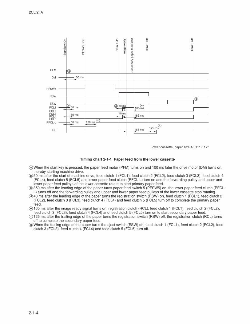
2CJ/2FA
2-1-4
PFM
DM
PFSW5
RSW
ESWFCL1FCL2FCL3FCL4FCL5
PFCL-L
RCL
Sta
rt k
ey: O
n
PF
SW
5 : O
n
RS
W :
On
Imag
e re
ady
Sec
onda
ry p
aper
feed
sta
rt
RS
W :
Off
ES
W :
Off
100 ms
50 ms
50 ms
50 ms 850 ms
40 ms165 ms
165 ms
165 ms 125 ms
40 ms
a
b
c
d e
f
g
Lower cassette, paper size A3/11" × 17"
Timing chart 2-1-1 Paper feed from the lower cassette
aWhen the start key is pressed, the paper feed motor (PFM) turns on and 100 ms later the drive motor (DM) turns on,thereby starting machine drive.
b50 ms after the start of machine drive, feed clutch 1 (FCL1), feed clutch 2 (FCL2), feed clutch 3 (FCL3), feed clutch 4(FCL4), feed clutch 5 (FCL5) and lower paper feed clutch (PFCL-L) turn on and the forwarding pulley and upper andlower paper feed pulleys of the lower cassette rotate to start primary paper feed.
c850 ms after the leading edge of the paper turns paper feed switch 5 (PFSW5) on, the lower paper feed clutch (PFCL-L) turns off and the forwarding pulley and upper and lower paper feed pulleys of the lower cassette stop rotating.
d40 ms after the leading edge of the paper turns the registration switch (RSW) on, feed clutch 1 (FCL1), feed clutch 2(FCL2), feed clutch 3 (FCL3), feed clutch 4 (FCL4) and feed clutch 5 (FCL5) turn off to complete the primary paperfeed.
e165 ms after the image ready signal turns on, registration clutch (RCL), feed clutch 1 (FCL1), feed clutch 2 (FCL2),feed clutch 3 (FCL3), feed clutch 4 (FCL4) and feed clutch 5 (FCL5) turn on to start secondary paper feed.
f125 ms after the trailing edge of the paper turns the registration switch (RSW) off, the registration clutch (RCL) turnsoff to complete the secondary paper feed.
gWhen the trailing edge of the paper turns the eject switch (ESW) off, feed clutch 1 (FCL1), feed clutch 2 (FCL2), feedclutch 3 (FCL3), feed clutch 4 (FCL4) and feed clutch 5 (FCL5) turn off.
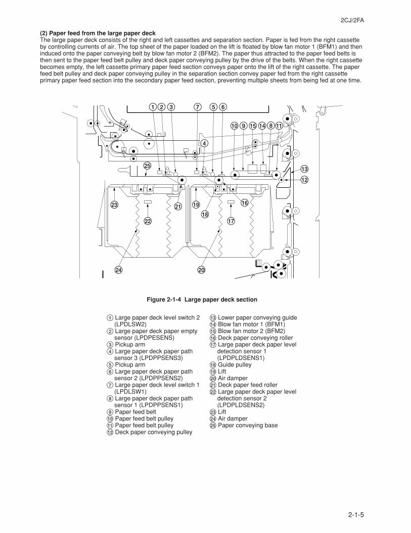
2CJ/2FA
2-1-5
(2) Paper feed from the large paper deckThe large paper deck consists of the right and left cassettes and separation section. Paper is fed from the right cassetteby controlling currents of air. The top sheet of the paper loaded on the lift is floated by blow fan motor 1 (BFM1) and theninduced onto the paper conveying belt by blow fan motor 2 (BFM2). The paper thus attracted to the paper feed belts isthen sent to the paper feed belt pulley and deck paper conveying pulley by the drive of the belts. When the right cassettebecomes empty, the left cassette primary paper feed section conveys paper onto the lift of the right cassette. The paperfeed belt pulley and deck paper conveying pulley in the separation section convey paper fed from the right cassetteprimary paper feed section into the secondary paper feed section, preventing multiple sheets from being fed at one time.
1 7 6
09%$8!
#
@
^
&*
5
4
23
¤
‹ (⁄
)›
fi
Figure 2-1-4 Large paper deck section
1 Large paper deck level switch 2(LPDLSW2)
2 Large paper deck paper emptysensor (LPDPESENS)
3 Pickup arm4 Large paper deck paper path
sensor 3 (LPDPPSENS3)5 Pickup arm6 Large paper deck paper path
sensor 2 (LPDPPSENS2)7 Large paper deck level switch 1
(LPDLSW1)8 Large paper deck paper path
sensor 1 (LPDPPSENS1)9 Paper feed belt0 Paper feed belt pulley! Paper feed belt pulley@ Deck paper conveying pulley
# Lower paper conveying guide$ Blow fan motor 1 (BFM1)% Blow fan motor 2 (BFM2)^ Deck paper conveying roller& Large paper deck paper level
detection sensor 1(LPDPLDSENS1)
* Guide pulley( Lift) Air damper⁄ Deck paper feed roller¤ Large paper deck paper level
detection sensor 2(LPDPLDSENS2)
‹ Lift› Air damperfi Paper conveying base
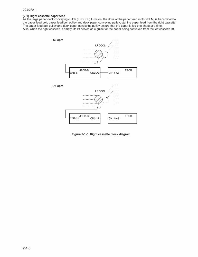
2CJ/2FA-1
2-1-6
(2-1) Right cassette paper feedAs the large paper deck conveying clutch (LPDCCL) turns on, the drive of the paper feed motor (PFM) is transmitted tothe paper feed belt, paper feed belt pulley and deck paper conveying pulley, starting paper feed from the right cassette.The paper feed belt pulley and deck paper conveying pulley ensure that the paper is fed one sheet at a time.Also, when the right cassette is empty, its lift serves as a guide for the paper being conveyed from the left cassette lift.
Figure 2-1-5 Right cassette block diagram
LPDCCL
JPCB-BCN5-6
EPCBCN14-A8CN2-A2
LPDCCL
JPCB-BCN7-21
EPCBCN14-A8CN3-17
• 63 cpm
• 75 cpm
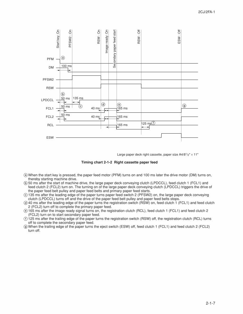
2CJ/2FA-1
2-1-7
aWhen the start key is pressed, the paper feed motor (PFM) turns on and 100 ms later the drive motor (DM) turns on,thereby starting machine drive.
b50 ms after the start of machine drive, the large paper deck conveying clutch (LPDCCL), feed clutch 1 (FCL1) andfeed clutch 2 (FCL2) turn on. The turning on of the large paper deck conveying clutch (LPDCCL) triggers the drive ofthe paper feed belt pulley and paper feed belts and primary paper feed starts.
c135 ms after the leading edge of the paper turns paper feed switch 2 (PFSW2) on, the large paper deck conveyingclutch (LPDCCL) turns off and the drive of the paper feed belt pulley and paper feed belts stops.
d40 ms after the leading edge of the paper turns the registration switch (RSW) on, feed clutch 1 (FCL1) and feed clutch2 (FCL2) turn off to complete the primary paper feed.
e165 ms after the image ready signal turns on, the registration clutch (RCL), feed clutch 1 (FCL1) and feed clutch 2(FCL2) turn on to start secondary paper feed.
f125 ms after the trailing edge of the paper turns the registration switch (RSW) off, the registration clutch (RCL) turnsoff to complete the secondary paper feed.
gWhen the trailing edge of the paper turns the eject switch (ESW) off, feed clutch 1 (FCL1) and feed clutch 2 (FCL2)turn off.
PFM
100 ms
50 ms
40 ms
40 ms
165 ms
165 ms
165 ms 125 ms
135 ms
50 ms
50 ms
DM
PFSW2
RSW
LPDCCL
FCL1
FCL2
RCL
ESW
Sta
rt k
ey: O
n
PF
SW
2 : O
n
RS
W :
On
RS
W :
Off
Imag
e re
ady:
On
ES
W :
Off
Sec
onda
ry p
aper
feed
sta
rt
a
b
c d e
f
g
Large paper deck right cassette, paper size A4/81/2" × 11"
Timing chart 2-1-2 Right cassette paper feed
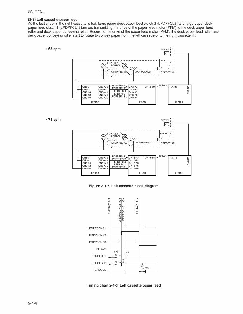
2CJ/2FA-1
2-1-8
(2-2) Left cassette paper feedAs the last sheet in the right cassette is fed, large paper deck paper feed clutch 2 (LPDPFCL2) and large paper deckpaper feed clutch 1 (LPDPFCL1) turn on, transmitting the drive of the paper feed motor (PFM) to the deck paper feedroller and deck paper conveying roller. Receiving the drive of the paper feed motor (PFM), the deck paper feed roller anddeck paper conveying roller start to rotate to convey paper from the left cassette onto the right cassette lift.
Timing chart 2-1-3 Left cassette paper feed
Figure 2-1-6 Left cassette block diagram
LPDPPSENS1
LPDPFCL1
LPDPPSENS2LPDPPSENS3
LPDPFCL2LPDPFCL1
LPDPPSENS1
CN8-7CN8-4CN9-14CN9-12CN8-10
CN3-A13CN3-A14CN3-A11CN3-A10CN3-A12
JPCB-B
CN3-A3CN3-A2CN3-A5CN3-A6CN3-A4
CN15-B9
EPCB
CN3-B2
CN
8-B
5
JPCB-A
PFSW2
LPDPFCL2
LPDPPSENS3 LPDPPSENS2
PFSW2
LPDPPSENS1
LPDPFCL1
LPDPPSENS2LPDPPSENS3
LPDPFCL2LPDPFCL1
LPDPPSENS1
CN8-7CN8-4CN9-14CN9-12CN8-10
CN3-A13CN3-A14CN3-A11CN3-A10CN3-A12
JPCB-A
CN13-A3CN13-A2CN13-A5CN13-A6CN13-A4
CN15-B8
EPCB
CN3-11
CN
8-B
3
JPCB-B
PFSW2
LPDPFCL2
LPDPPSENS3 LPDPPSENS2
PFSW2
Sta
rt k
ey: O
n
LPD
PP
SE
NS
2 : O
nLP
DP
PS
EN
S1
: On
PF
SW
2 : O
n
LPDPPSENS1
LPDPPSENS2
LPDPPSENS3
PFSW2
LPDPFCL1
LPDPFCL2
LPDCCL
50 ms
50 ms
135 ms
ac
bd
• 63 cpm
• 75 cpm
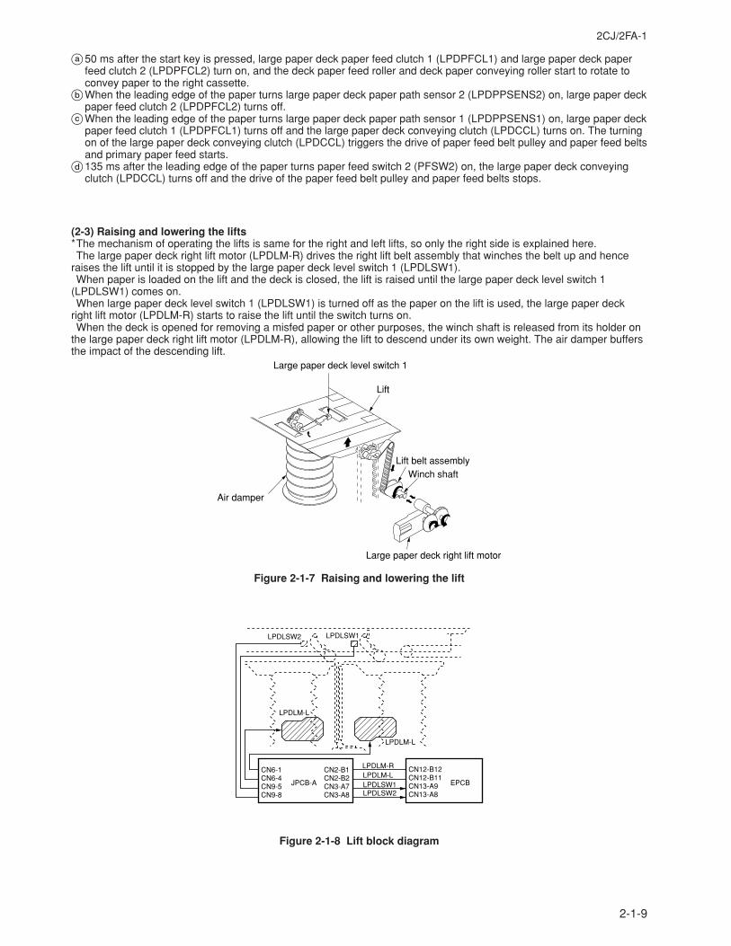
2CJ/2FA-1
2-1-9
(2-3) Raising and lowering the lifts*The mechanism of operating the lifts is same for the right and left lifts, so only the right side is explained here.The large paper deck right lift motor (LPDLM-R) drives the right lift belt assembly that winches the belt up and hence
raises the lift until it is stopped by the large paper deck level switch 1 (LPDLSW1).When paper is loaded on the lift and the deck is closed, the lift is raised until the large paper deck level switch 1
(LPDLSW1) comes on.When large paper deck level switch 1 (LPDLSW1) is turned off as the paper on the lift is used, the large paper deck
right lift motor (LPDLM-R) starts to raise the lift until the switch turns on.When the deck is opened for removing a misfed paper or other purposes, the winch shaft is released from its holder on
the large paper deck right lift motor (LPDLM-R), allowing the lift to descend under its own weight. The air damper buffersthe impact of the descending lift.
Large paper deck level switch 1
Air damper
Large paper deck right lift motor
Winch shaftLift belt assembly
Lift
Figure 2-1-7 Raising and lowering the lift
LPDLSW1LPDLSW2
CN6-1CN6-4CN9-5CN9-8
CN2-B1CN2-B2CN3-A7CN3-A8
JPCB-A
CN12-B12CN12-B11CN13-A9CN13-A8
EPCB
LPDLSW2
LPDLM-L
LPDLSW1
LPDLM-RLPDLM-L
LPDLM-L
Figure 2-1-8 Lift block diagram
a50 ms after the start key is pressed, large paper deck paper feed clutch 1 (LPDPFCL1) and large paper deck paperfeed clutch 2 (LPDPFCL2) turn on, and the deck paper feed roller and deck paper conveying roller start to rotate toconvey paper to the right cassette.
bWhen the leading edge of the paper turns large paper deck paper path sensor 2 (LPDPPSENS2) on, large paper deckpaper feed clutch 2 (LPDPFCL2) turns off.
cWhen the leading edge of the paper turns large paper deck paper path sensor 1 (LPDPPSENS1) on, large paper deckpaper feed clutch 1 (LPDPFCL1) turns off and the large paper deck conveying clutch (LPDCCL) turns on. The turningon of the large paper deck conveying clutch (LPDCCL) triggers the drive of paper feed belt pulley and paper feed beltsand primary paper feed starts.
d135 ms after the leading edge of the paper turns paper feed switch 2 (PFSW2) on, the large paper deck conveyingclutch (LPDCCL) turns off and the drive of the paper feed belt pulley and paper feed belts stops.
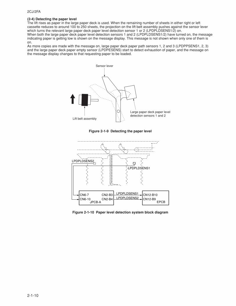
2CJ/2FA
2-1-10
(2-4) Detecting the paper levelThe lift rises as paper in the large paper deck is used. When the remaining number of sheets in either right or leftcassette reduces to around 100 to 250 sheets, the projection on the lift belt assembly pushes against the sensor leverwhich turns the relevant large paper deck paper level detection sensor 1 or 2 (LPDPLDSENS1/2) on.When both the large paper deck paper level detection sensors 1 and 2 (LPDPLDSENS1/2) have turned on, the messageindicating paper is getting low is shown on the message display. This message is not shown when only one of them ison.As more copies are made with the message on, large paper deck paper path sensors 1, 2 and 3 (LPDPPSENS1, 2, 3)and the large paper deck paper empty sensor (LPDPESENS) start to detect exhaustion of paper, and the message onthe message display changes to that requesting paper to be loaded.
Sensor lever
Large paper deck paper leveldetection sensors 1 and 2
Lift belt assembly
Figure 2-1-9 Detecting the paper level
CN6-7CN6-10
CN2-B3CN2-B4
JPCB-A
CN12-B10CN12-B9
EPCB
LPDPLDSENS2
LPDPLDSENS2
LPDPLDSENS1
LPDPLDSENS1
Figure 2-1-10 Paper level detection system block diagram
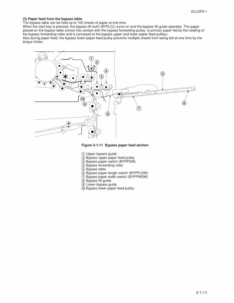
2CJ/2FA-1
2-1-11
(3) Paper feed from the bypass tableThe bypass table can be hold up to 100 sheets of paper at one time.When the start key is pressed, the bypass lift cluth (BYPLCL) turns on and the bypass lift guide operates. The paperplaced on the bypass table comes into contact with the bypass forwarding pulley, is primary paper fed by the rotating ofthe bypass forwarding roller and is conveyed to the bypass upper and lower paper feed pulleys.Also during paper feed, the bypass lower paper feed pulley prevents multiple sheets from being fed at one time by thetorque limiter.
54
3
21
67
8
90
Figure 2-1-11 Bypass paper feed section
1 Upper bypass guide2 Bypass upper paper feed pulley3 Bypass paper switch (BYPPSW)4 Bypass forwarding roller5 Bypass table6 Bypass paper length switch (BYPPLSW)7 Bypass paper width switch (BYPPWSW)8 Bypass lift guide9 Lower bypass guide0 Bypass lower paper feed pulley
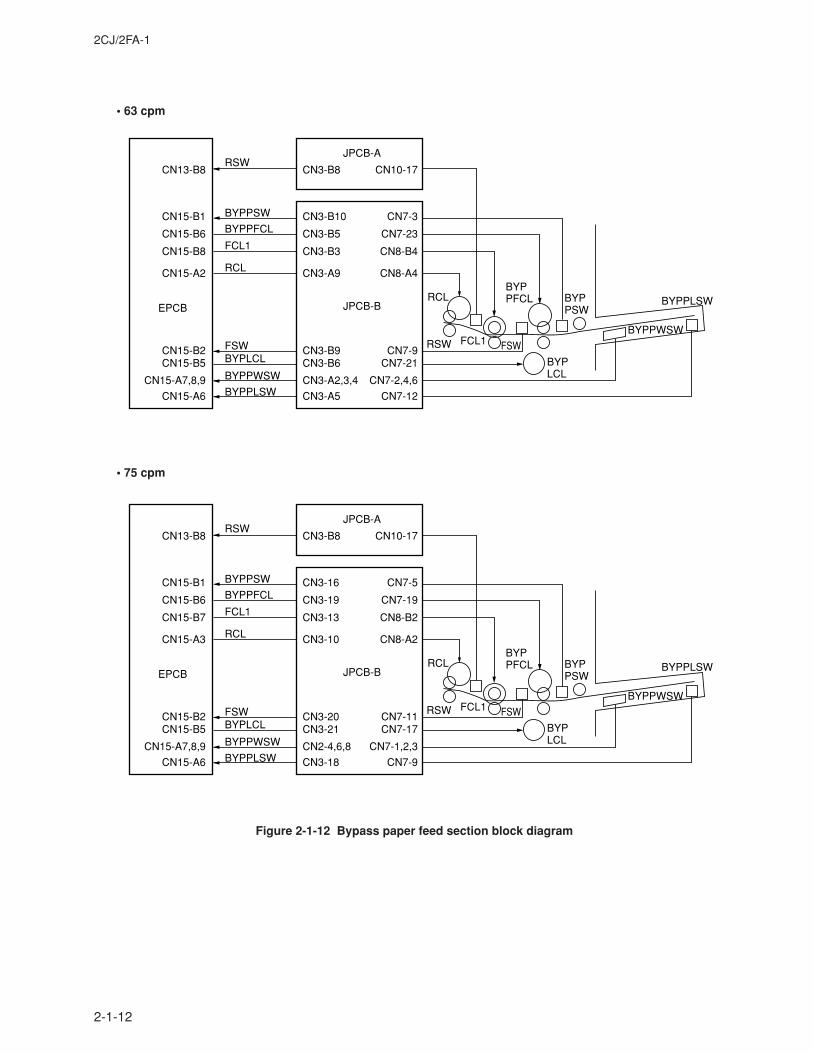
2CJ/2FA-1
2-1-12
Figure 2-1-12 Bypass paper feed section block diagram
RCL
RCL
RSW
RSW
FCL1
FCL1
FSWFSW
BYPLCL
BYPLCL
BYPPSW
BYPPSW
BYPPFCL
BYPPFCL
BYPPLSW
BYPPLSW
BYPPWSW
BYPPWSW
JPCB-BEPCB
JPCB-A
CN7-3
CN7-23
CN10-17
CN7-21
CN7-12
CN7-2,4,6
CN8-A4
CN7-9
CN8-B4
CN15-B1
CN15-B6
CN13-B8
CN15-B5
CN15-A6
CN15-A7,8,9
CN15-A2
CN15-B2
CN15-B8
CN3-B10
CN3-B5
CN3-B8
CN3-B6
CN3-A5
CN3-A2,3,4
CN3-A9
CN3-B9
CN3-B3
RCL
RCL
RSW
RSW
FCL1
FCL1
FSWFSW
BYPLCL
BYPLCL
BYPPSW
BYPPSW
BYPPFCL
BYPPFCL
BYPPLSW
BYPPLSW
BYPPWSW
BYPPWSW
JPCB-BEPCB
JPCB-A
CN7-5
CN7-19
CN10-17
CN7-17
CN7-9
CN7-1,2,3
CN8-A2
CN7-11
CN8-B2
CN15-B1
CN15-B6
CN13-B8
CN15-B5
CN15-A6
CN15-A7,8,9
CN15-A3
CN15-B2
CN15-B7
CN3-16
CN3-19
CN3-B8
CN3-21
CN3-18
CN2-4,6,8
CN3-10
CN3-20
CN3-13
• 63 cpm
• 75 cpm
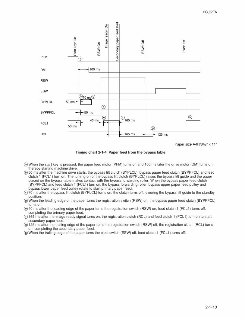
2CJ/2FA
2-1-13
Sta
rt k
ey: O
n
RS
W: O
n
Imag
e re
ady:
On
Sec
onda
ry p
aper
feed
sta
rt
RS
W: O
ff
ES
W: O
ff
DM
RSW
BYPLCL
BYPPFCL
ESW
FCL1
RCL
PFM
50 ms
50 ms
70 ms
100 ms
40 ms 165 ms
165 ms 125 ms
50 ms
a
b c
d
e f h
g
Paper size A4R/81/2" × 11"
Timing chart 2-1-4 Paper feed from the bypass table
aWhen the start key is pressed, the paper feed motor (PFM) turns on and 100 ms later the drive motor (DM) turns on,thereby starting machine drive.
b50 ms after the machine drive starts, the bypass lift clutch (BYPLCL), bypass paper feed clutch (BYPPFCL) and feedclutch 1 (FCL1) turn on. The turning on of the bypass lift clutch (BYPLCL) raises the bypass lift guide and the paperplaced on the bypass table makes contact with the bypass forwarding roller. When the bypass paper feed clutch(BYPPFCL) and feed clutch 1 (FCL1) turn on, the bypass forwarding roller, bypass upper paper feed pulley andbypass lower paper feed pulley rotate to start primary paper feed.
c70 ms after the bypass lift clutch (BYPLCL) turns on, the clutch turns off, lowering the bypass lift guide to the standbyposition.
dWhen the leading edge of the paper turns the registration switch (RSW) on, the bypass paper feed clutch (BYPPFCL)turns off.
e40 ms after the leading edge of the paper turns the registration switch (RSW) on, feed clutch 1 (FCL1) turns off,completing the primary paper feed.
f165 ms after the image ready signal turns on, the registration clutch (RCL) and feed clutch 1 (FCL1) turn on to startsecondary paper feed.
g125 ms after the trailing edge of the paper turns the registration switch (RSW) off, the registration clutch (RCL) turnsoff, completing the secondary paper feed.
hWhen the trailing edge of the paper turns the eject switch (ESW) off, feed clutch 1 (FCL1) turns off.
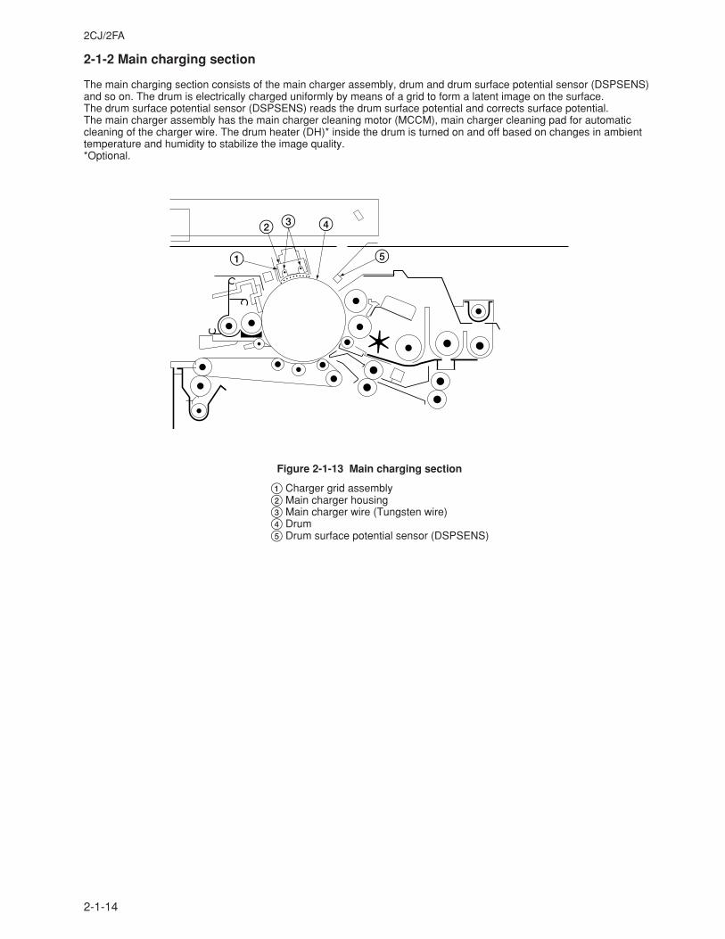
2CJ/2FA
2-1-14
2-1-2 Main charging section
The main charging section consists of the main charger assembly, drum and drum surface potential sensor (DSPSENS)and so on. The drum is electrically charged uniformly by means of a grid to form a latent image on the surface.The drum surface potential sensor (DSPSENS) reads the drum surface potential and corrects surface potential.The main charger assembly has the main charger cleaning motor (MCCM), main charger cleaning pad for automaticcleaning of the charger wire. The drum heater (DH)* inside the drum is turned on and off based on changes in ambienttemperature and humidity to stabilize the image quality.*Optional.
1
2 3 4
5
Figure 2-1-13 Main charging section
1 Charger grid assembly2 Main charger housing3 Main charger wire (Tungsten wire)4 Drum5 Drum surface potential sensor (DSPSENS)
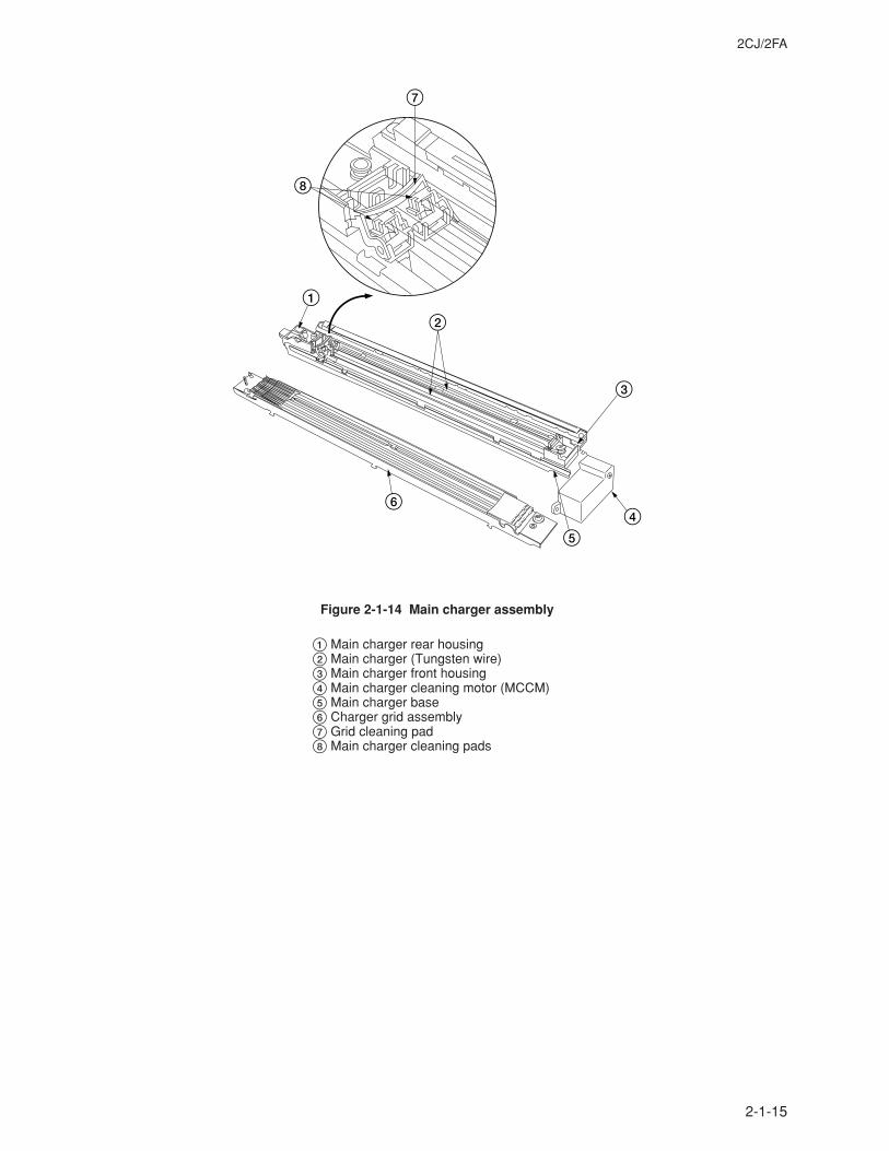
2CJ/2FA
2-1-15
8
7
1
2
3
45
6
Figure 2-1-14 Main charger assembly
1 Main charger rear housing2 Main charger (Tungsten wire)3 Main charger front housing4 Main charger cleaning motor (MCCM)5 Main charger base6 Charger grid assembly7 Grid cleaning pad8 Main charger cleaning pads
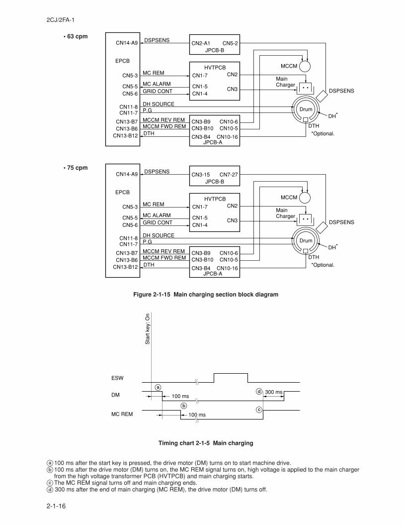
2CJ/2FA-1
2-1-16
Sta
rt k
ey: O
n
ESW
DM
MC REM
100 ms300 ms
100 ms
b
a
c
d
Timing chart 2-1-5 Main charging
a100 ms after the start key is pressed, the drive motor (DM) turns on to start machine drive.b100 ms after the drive motor (DM) turns on, the MC REM signal turns on, high voltage is applied to the main charger
from the high voltage transformer PCB (HVTPCB) and main charging starts.cThe MC REM signal turns off and main charging ends.d 300 ms after the end of main charging (MC REM), the drive motor (DM) turns off.
Figure 2-1-15 Main charging section block diagram
EPCB
CN5-3
CN14-A9
CN13-B12
DTHDTH *Optional.
CN5-5CN5-6
CN1-7
CN1-5CN1-4GRID CONT
MC ALARM
MC REM
DH SOURCEP.G Drum
HVTPCBCN2
CN3
CN11-8CN11-7
MainCharger
DH*
MCCM
DSPSENS
DSPSENS
CN13-B7CN13-B6
MCCM REV REMMCCM FWD REM
CN3-B9CN3-B10
CN3-B4
CN10-6CN10-5
CN10-16JPCB-A
JPCB-BCN2-A1 CN5-2
EPCB
CN5-3
CN14-A9
CN13-B12
DTHDTH *Optional.
CN5-5CN5-6
CN1-7
CN1-5CN1-4GRID CONT
MC ALARM
MC REM
DH SOURCEP.G Drum
HVTPCBCN2
CN3
CN11-8CN11-7
MainCharger
DH*
MCCM
DSPSENS
DSPSENS
CN13-B7CN13-B6
MCCM REV REMMCCM FWD REM
CN3-B9CN3-B10
CN3-B4
CN10-6CN10-5
CN10-16JPCB-A
JPCB-BCN3-15 CN7-27
• 63 cpm
• 75 cpm
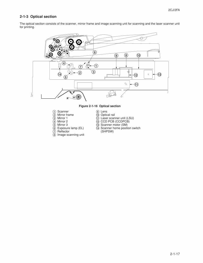
2CJ/2FA
2-1-17
2-1-3 Optical section
The optical section consists of the scanner, mirror frame and image scanning unit for scanning and the laser scanner unitfor printing.
$5
2
1
6
37
4
9 08
@ #
!
Figure 2-1-16 Optical section
1 Scanner2 Mirror frame3 Mirror 14 Mirror 25 Mirror 36 Exposure lamp (EL)7 Reflector8 Image scanning unit
9 Lens0 Optical rail! Laser scanner unit (LSU)@ CCD PCB (CCDPCB)# Scanner motor (SM)$ Scanner home position switch
(SHPSW)
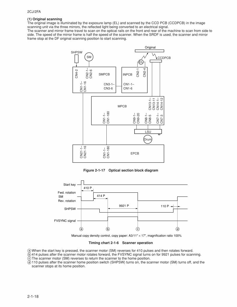
2CJ/2FA
2-1-18
(1) Original scanningThe original image is illuminated by the exposure lamp (EL) and scanned by the CCD PCB (CCDPCB) in the imagescanning unit via the three mirrors, the reflected light being converted to an electrical signal.The scanner and mirror frame travel to scan on the optical rails on the front and rear of the machine to scan from side toside. The speed of the mirror frame is half the speed of the scanner. When the SRDF is used, the scanner and mirrorframe stop at the DF original scanning position to start scanning.
CN
1-1–
CN
2-1–
CN
4-2
CN
2-6
CN
2-1
CN
2-4
CN
1-18
0
CN
13-1
–C
N13
-11
CN
14-1
–C
N14
-12
CN
7-1–
CN
7-3
CN
8-1–
CN
8-5
CN
9-1–
CN
9-20
CN
1-1–
CN
1-16
CN
21-1
–C
N21
-16
CN
1-1–
CN
1-18
0
CN3-6CN3-1–
CN1-6CN1-1–
SMPCB INPCB
CCDPCB
EPCB
MPCB
SM
SHPSW
EL
Original
Drum
LSU
Figure 2-1-17 Optical section block diagram
Manual copy density control, copy paper: A3/11" × 17", magnification ratio 100%
Start key
SMFwd. rotation
Rev. rotation
SHPSW
FVSYNC signal
410 P
414 P
9921 P 110 P
a b c d
Timing chart 2-1-6 Scanner operation
aWhen the start key is pressed, the scanner motor (SM) reverses for 410 pulses and then rotates forward.b414 pulses after the scanner motor rotates forward, the FVSYNC signal turns on for 9921 pulses for scanning.cThe scanner motor (SM) reverses to return the scanner to the home position.d110 pulses after the scanner home position switch (SHPSW) turns on, the scanner motor (SM) turns off, and the
scanner stops at its home position.
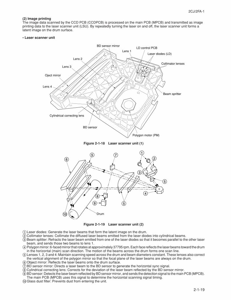
2CJ/2FA-1
2-1-19
(2) Image printingThe image data scanned by the CCD PCB (CCDPCB) is processed on the main PCB (MPCB) and transmitted as imageprinting data to the laser scanner unit (LSU). By repeatedly turning the laser on and off, the laser scanner unit forms alatent image on the drum surface.
• Laser scanner unit
Oject mirror
BD sensor mirror
Collimator lenses
Beam spritter
Lens 1LD control PCB
Laser diodes (LD)
BD sensor
Cylindrical correcting lens
Polygon motor (PM)
Lens 4
Lens 3
Lens 2
Figure 2-1-18 Laser scanner unit (1)
12
3
5
5
6
4
0
5 7
8
9
Drum
Figure 2-1-19 Laser scanner unit (2)
1Laser diodes: Generate the laser beams that form the latent image on the drum.2Collimator lenses: Collimate the diffused laser beams emitted from the laser diodes into cylindrical beams.3Beam splitter: Refracts the laser beam emitted from one of the laser diodes so that it becomes parallel to the other laser
beam, and sends those two beams to lens 1.4Polygon mirror: 6-faced mirror that rotates at approximately 37795 rpm. Each face reflects the laser beams toward the drum
in the horizontal (main) scan direction. The motion of the beams across the drum forms one scan line.5Lenses 1, 2, 3 and 4: Maintain scanning speed across the drum and beam diameters constant. These lenses also correct
the vertical alignment of the polygon mirror so that the focal plane of the laser beams are always on the drum.6Object mirror: Reflects the laser beams onto the drum surface.7BD sensor mirror: Directs a laser beam to the BD sensor to generate the horizontal sync signal.8Cylindrical correcting lens: Corrects for the deviation of the laser beam reflected by the BD sensor mirror.9BD sensor: Detects the laser beam reflected by BD sensor mirror, and sends the detection signal to the main PCB (MPCB).
The main PCB (MPCB) uses this signal to determine the horizontal scanning signal timing.0Glass dust filter: Prevents dust from entering the unit.
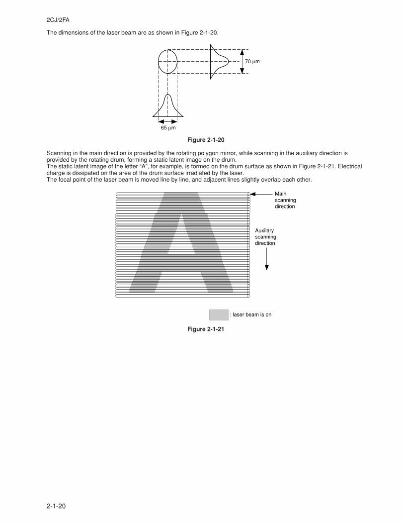
2CJ/2FA
2-1-20
The dimensions of the laser beam are as shown in Figure 2-1-20.
65 µm
70 µm
Figure 2-1-20
Scanning in the main direction is provided by the rotating polygon mirror, while scanning in the auxiliary direction isprovided by the rotating drum, forming a static latent image on the drum.The static latent image of the letter “A”, for example, is formed on the drum surface as shown in Figure 2-1-21. Electricalcharge is dissipated on the area of the drum surface irradiated by the laser.The focal point of the laser beam is moved line by line, and adjacent lines slightly overlap each other.
Mainscanningdirection
Auxilaryscanningdirection
: laser beam is on
Figure 2-1-21
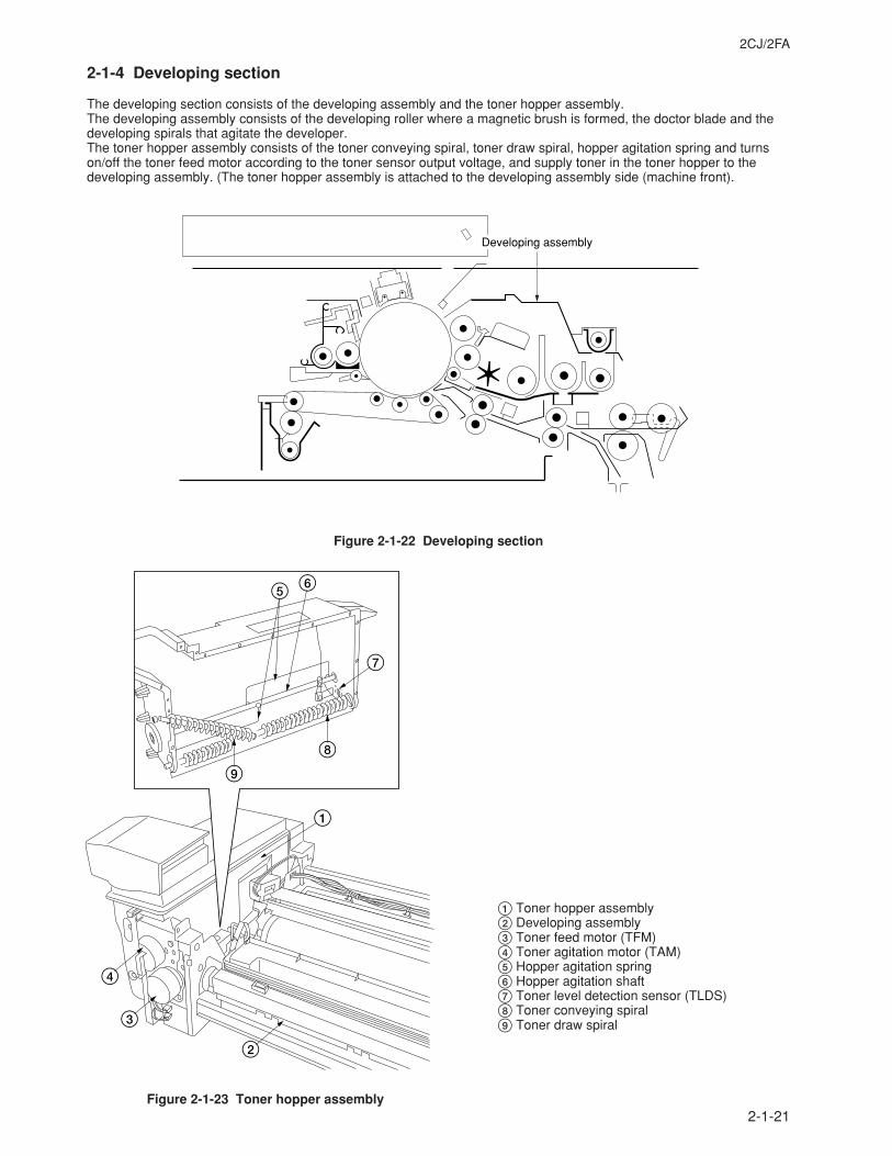
2CJ/2FA
2-1-21
2-1-4 Developing section
The developing section consists of the developing assembly and the toner hopper assembly.The developing assembly consists of the developing roller where a magnetic brush is formed, the doctor blade and thedeveloping spirals that agitate the developer.The toner hopper assembly consists of the toner conveying spiral, toner draw spiral, hopper agitation spring and turnson/off the toner feed motor according to the toner sensor output voltage, and supply toner in the toner hopper to thedeveloping assembly. (The toner hopper assembly is attached to the developing assembly side (machine front).
Developing assembly
Figure 2-1-22 Developing section
3
4
2
1
9
8
7
65
Figure 2-1-23 Toner hopper assembly
1 Toner hopper assembly2 Developing assembly3 Toner feed motor (TFM)4 Toner agitation motor (TAM)5 Hopper agitation spring6 Hopper agitation shaft7 Toner level detection sensor (TLDS)8 Toner conveying spiral9 Toner draw spiral
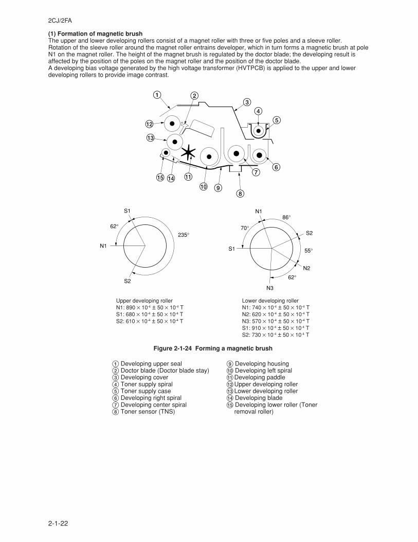
2CJ/2FA
2-1-22
(1) Formation of magnetic brushThe upper and lower developing rollers consist of a magnet roller with three or five poles and a sleeve roller.Rotation of the sleeve roller around the magnet roller entrains developer, which in turn forms a magnetic brush at poleN1 on the magnet roller. The height of the magnet brush is regulated by the doctor blade; the developing result isaffected by the position of the poles on the magnet roller and the position of the doctor blade.A developing bias voltage generated by the high voltage transformer (HVTPCB) is applied to the upper and lowerdeveloping rollers to provide image contrast.
1 23
45
67
890
!$
#
@
%
Upper developing roller Lower developing rollerN1: 890 × 10-4 ± 50 × 10-4 T N1: 740 × 10-4 ± 50 × 10-4 TS1: 680 × 10-4 ± 50 × 10-4 T N2: 620 × 10-4 ± 50 × 10-4 TS2: 610 × 10-4 ± 50 × 10-4 T N3: 570 × 10-4 ± 50 × 10-4 T
S1: 910 × 10-4 ± 50 × 10-4 TS2: 730 × 10-4 ± 50 × 10-4 T
Figure 2-1-24 Forming a magnetic brush
1 Developing upper seal2 Doctor blade (Doctor blade stay)3 Developing cover4 Toner supply spiral5 Toner supply case6 Developing right spiral7 Developing center spiral8 Toner sensor (TNS)
N1
S1
62°235°
S2
S1
N1
N2
N3
S270°
86°
55°
62°
9 Developing housing0 Developing left spiral!Developing paddle@Upper developing roller#Lower developing roller$ Developing blade% Developing lower roller (Toner
removal roller)
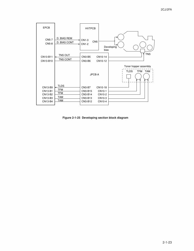
2CJ/2FA
2-1-23
HVTPCB
CN1-3
CN1-2
EPCB
CN5-7
CN5-8
CN13-B11
CN13-B10
CN13-B1CN13-B2CN13-B3CN13-B4
CN13-B9
D. BIAS CONT
TNS CONT
TNS OUT
D. BIAS REM
Toner hopper assembly
CN5
Developingbias
TNS
TAM
TAMTAM
TLDS
TLDS
TFM
TFMTFM
CN10-14
CN10-12
CN10-1CN10-2CN10-3CN10-4
CN10-18
CN3-B5
CN3-B6
CN3-B15CN3-B14CN3-B13CN3-B12
CN3-B7
JPCB-A
Figure 2-1-25 Developing section block diagram
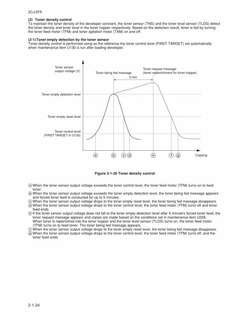
2CJ/2FA
2-1-24
(2) Toner density controlTo maintain the toner density of the developer constant, the toner sensor (TNS) and the toner level sensor (TLDS) detectthe toner density and toner level in the toner hopper respectively. Based on the detection result, toner is fed by turningthe toner feed motor (TFM) and toner agitation motor (TAM) on and off.
(2-1)Toner empty detection by the toner sensorToner density control is performed using as the reference the toner control level (FIRST TARGET) set automaticallywhen maintenance item U130 is run after loading developer.
Toner request message(toner replenishment for toner hopper)Toner being fed message
5 min
Copying
Toner sensoroutput voltage (V)
Toner empty detection level
Toner empty reset level
Toner control level (FIRST TARGET in U130)
a b cd e f g
Figure 2-1-26 Toner density control
aWhen the toner sensor output voltage exceeds the toner control level, the toner feed motor (TFM) turns on to feedtoner.
bWhen the toner sensor output voltage exceeds the toner empty detection level, the toner being fed message appearsand forced toner feed is conducted for up to 5 minutes.
cWhen the toner sensor output voltage drops to the toner empty reset level, the toner being fed message disappears.dWhen the toner sensor output voltage drops to the toner control level, the toner feed motor (TFM) turns off and toner
feed ends.e If the toner sensor output voltage does not fall to the toner empty detection level after 5-minute's forced toner feed, the
toner request message appears and copies are made based on the conditions set in maintenance item U258.When toner is replenished into the toner hopper and the toner level sensor (TLDS) turns on, the toner feed motor(TFM) turns on to feed toner. The toner being fed message appears.
fWhen the toner sensor output voltage drops to the toner empty reset level, the toner being fed message disappears.gWhen the toner sensor output voltage drops to the toner control level, the toner feed motor (TFM) turns off, and the
toner feed ends.
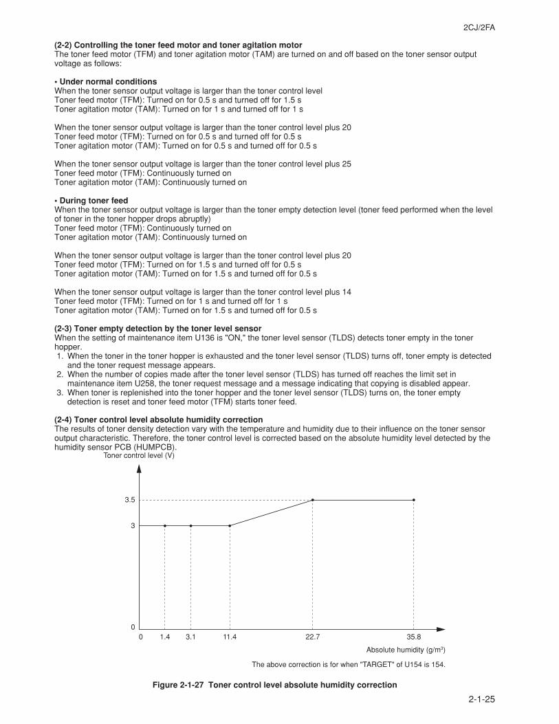
2CJ/2FA
2-1-25
(2-2) Controlling the toner feed motor and toner agitation motorThe toner feed motor (TFM) and toner agitation motor (TAM) are turned on and off based on the toner sensor outputvoltage as follows:
• Under normal conditionsWhen the toner sensor output voltage is larger than the toner control levelToner feed motor (TFM): Turned on for 0.5 s and turned off for 1.5 sToner agitation motor (TAM): Turned on for 1 s and turned off for 1 s
When the toner sensor output voltage is larger than the toner control level plus 20Toner feed motor (TFM): Turned on for 0.5 s and turned off for 0.5 sToner agitation motor (TAM): Turned on for 0.5 s and turned off for 0.5 s
When the toner sensor output voltage is larger than the toner control level plus 25Toner feed motor (TFM): Continuously turned onToner agitation motor (TAM): Continuously turned on
• During toner feedWhen the toner sensor output voltage is larger than the toner empty detection level (toner feed performed when the levelof toner in the toner hopper drops abruptly)Toner feed motor (TFM): Continuously turned onToner agitation motor (TAM): Continuously turned on
When the toner sensor output voltage is larger than the toner control level plus 20Toner feed motor (TFM): Turned on for 1.5 s and turned off for 0.5 sToner agitation motor (TAM): Turned on for 1.5 s and turned off for 0.5 s
When the toner sensor output voltage is larger than the toner control level plus 14Toner feed motor (TFM): Turned on for 1 s and turned off for 1 sToner agitation motor (TAM): Turned on for 1.5 s and turned off for 0.5 s
(2-3) Toner empty detection by the toner level sensorWhen the setting of maintenance item U136 is "ON," the toner level sensor (TLDS) detects toner empty in the tonerhopper.1. When the toner in the toner hopper is exhausted and the toner level sensor (TLDS) turns off, toner empty is detected
and the toner request message appears.2. When the number of copies made after the toner level sensor (TLDS) has turned off reaches the limit set in
maintenance item U258, the toner request message and a message indicating that copying is disabled appear.3. When toner is replenished into the toner hopper and the toner level sensor (TLDS) turns on, the toner empty
detection is reset and toner feed motor (TFM) starts toner feed.
(2-4) Toner control level absolute humidity correctionThe results of toner density detection vary with the temperature and humidity due to their influence on the toner sensoroutput characteristic. Therefore, the toner control level is corrected based on the absolute humidity level detected by thehumidity sensor PCB (HUMPCB).
Toner control level (V)
3.5
3
00 1.4 3.1 11.4 22.7 35.8
Absolute humidity (g/m3)
The above correction is for when "TARGET" of U154 is 154.
Figure 2-1-27 Toner control level absolute humidity correction
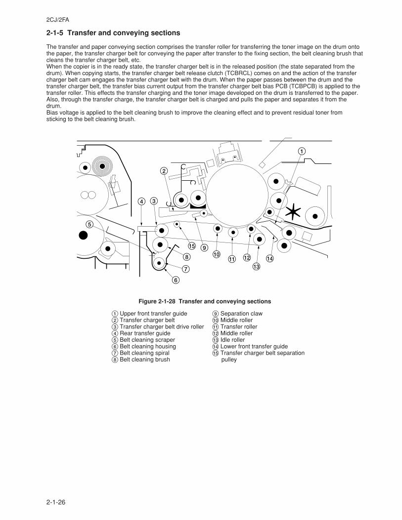
2CJ/2FA
2-1-26
2-1-5 Transfer and conveying sections
The transfer and paper conveying section comprises the transfer roller for transferring the toner image on the drum ontothe paper, the transfer charger belt for conveying the paper after transfer to the fixing section, the belt cleaning brush thatcleans the transfer charger belt, etc.When the copier is in the ready state, the transfer charger belt is in the released position (the state separated from thedrum). When copying starts, the transfer charger belt release clutch (TCBRCL) comes on and the action of the transfercharger belt cam engages the transfer charger belt with the drum. When the paper passes between the drum and thetransfer charger belt, the transfer bias current output from the transfer charger belt bias PCB (TCBPCB) is applied to thetransfer roller. This effects the transfer charging and the toner image developed on the drum is transferred to the paper.Also, through the transfer charge, the transfer charger belt is charged and pulls the paper and separates it from thedrum.Bias voltage is applied to the belt cleaning brush to improve the cleaning effect and to prevent residual toner fromsticking to the belt cleaning brush.
4 3
2
1
$#
@!0
9%
8
7
6
5
Figure 2-1-28 Transfer and conveying sections
1 Upper front transfer guide2 Transfer charger belt3 Transfer charger belt drive roller4 Rear transfer guide5 Belt cleaning scraper6 Belt cleaning housing7 Belt cleaning spiral8 Belt cleaning brush
9 Separation claw0 Middle roller! Transfer roller@ Middle roller# Idle roller$ Lower front transfer guide% Transfer charger belt separation
pulley
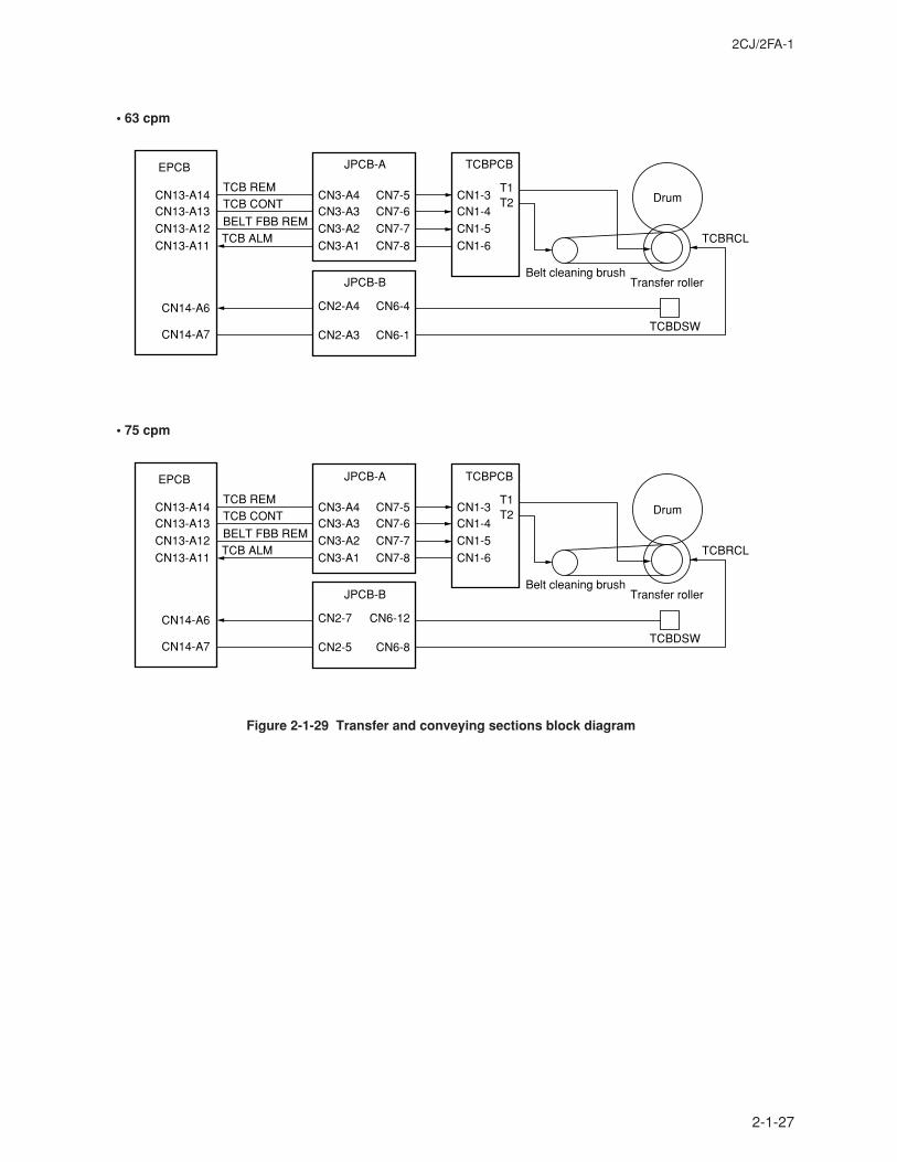
2CJ/2FA-1
2-1-27
Figure 2-1-29 Transfer and conveying sections block diagram
EPCB
CN13-A14CN13-A13
CN13-A12
CN13-A11
CN14-A7
CN14-A6
BELT FBB REMTCB ALM
TCB CONTTCB REM
Drum
Transfer rollerBelt cleaning brush
TCBRCL
TCBDSW
TCBPCB
CN1-3CN1-4
CN1-5
CN1-6
T1T2
JPCB-A
CN3-A4CN3-A3
CN3-A2
CN3-A1
CN7-5CN7-6
CN7-7
CN7-8
JPCB-B
CN2-A4
CN2-A3
CN6-4
CN6-1
EPCB
CN13-A14CN13-A13
CN13-A12
CN13-A11
CN14-A7
CN14-A6
BELT FBB REMTCB ALM
TCB CONTTCB REM
Drum
Transfer rollerBelt cleaning brush
TCBRCL
TCBDSW
TCBPCB
CN1-3CN1-4
CN1-5
CN1-6
T1T2
JPCB-A
CN3-A4CN3-A3
CN3-A2
CN3-A1
CN7-5CN7-6
CN7-7
CN7-8
JPCB-B
CN2-7
CN2-5
CN6-12
CN6-8
• 63 cpm
• 75 cpm
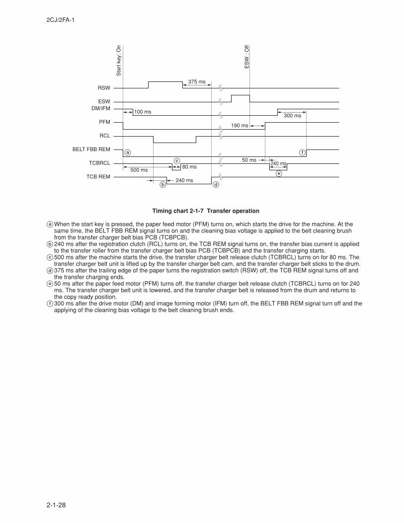
2CJ/2FA-1
2-1-28
RSW
ESWDM/IFM
PFM
RCL
BELT FBB REM
TCBRCL
TCB REM
Sta
rt k
ey: O
n
ES
W :
Off
100 ms
190 ms
300 ms
50 ms80 ms
240 ms
240 ms500 ms
375 ms
a
c
b d
e
f
Timing chart 2-1-7 Transfer operation
aWhen the start key is pressed, the paper feed motor (PFM) turns on, which starts the drive for the machine. At thesame time, the BELT FBB REM signal turns on and the cleaning bias voltage is applied to the belt cleaning brushfrom the transfer charger belt bias PCB (TCBPCB).
b240 ms after the registration clutch (RCL) turns on, the TCB REM signal turns on, the transfer bias current is appliedto the transfer roller from the transfer charger belt bias PCB (TCBPCB) and the transfer charging starts.
c500 ms after the machine starts the drive, the transfer charger belt release clutch (TCBRCL) turns on for 80 ms. Thetransfer charger belt unit is lifted up by the transfer charger belt cam, and the transfer charger belt sticks to the drum.
d375 ms after the trailing edge of the paper turns the registration switch (RSW) off, the TCB REM signal turns off andthe transfer charging ends.
e50 ms after the paper feed motor (PFM) turns off, the transfer charger belt release clutch (TCBRCL) turns on for 240ms. The transfer charger belt unit is lowered, and the transfer charger belt is released from the drum and returns tothe copy ready position.
f300 ms after the drive motor (DM) and image forming motor (IFM) turn off, the BELT FBB REM signal turn off and theapplying of the cleaning bias voltage to the belt cleaning brush ends.
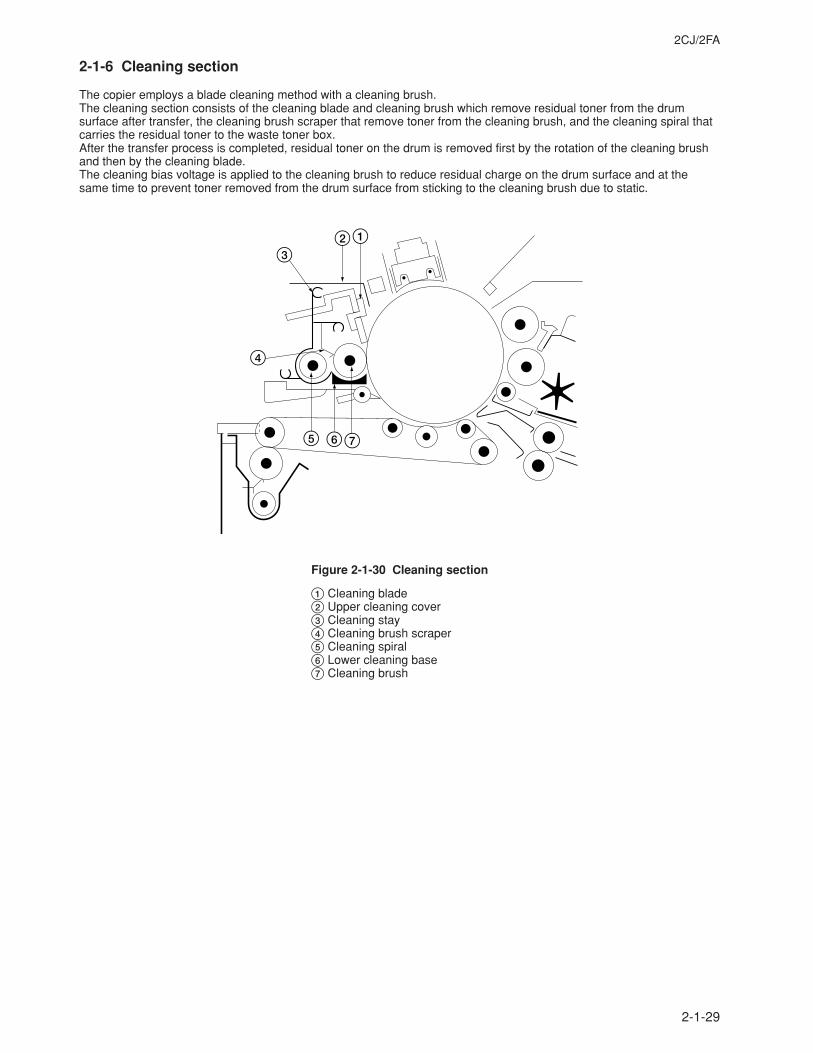
2CJ/2FA
2-1-29
2-1-6 Cleaning section
The copier employs a blade cleaning method with a cleaning brush.The cleaning section consists of the cleaning blade and cleaning brush which remove residual toner from the drumsurface after transfer, the cleaning brush scraper that remove toner from the cleaning brush, and the cleaning spiral thatcarries the residual toner to the waste toner box.After the transfer process is completed, residual toner on the drum is removed first by the rotation of the cleaning brushand then by the cleaning blade.The cleaning bias voltage is applied to the cleaning brush to reduce residual charge on the drum surface and at thesame time to prevent toner removed from the drum surface from sticking to the cleaning brush due to static.
123
4
5 67
Figure 2-1-30 Cleaning section
1 Cleaning blade2 Upper cleaning cover3 Cleaning stay4 Cleaning brush scraper5 Cleaning spiral6 Lower cleaning base7 Cleaning brush
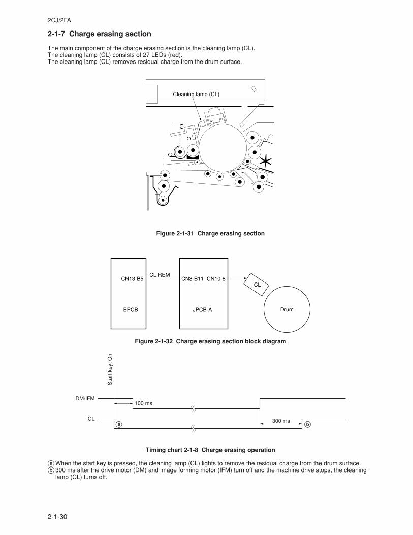
2CJ/2FA
2-1-30
2-1-7 Charge erasing section
The main component of the charge erasing section is the cleaning lamp (CL).The cleaning lamp (CL) consists of 27 LEDs (red).The cleaning lamp (CL) removes residual charge from the drum surface.
Cleaning lamp (CL)
Figure 2-1-31 Charge erasing section
EPCB
CN13-B5CL REM
CL
DrumJPCB-A
CN3-B11 CN10-8
Figure 2-1-32 Charge erasing section block diagram
DM/IFM100 ms
300 msCL
Sta
rt k
ey: O
n
a b
Timing chart 2-1-8 Charge erasing operation
aWhen the start key is pressed, the cleaning lamp (CL) lights to remove the residual charge from the drum surface.b300 ms after the drive motor (DM) and image forming motor (IFM) turn off and the machine drive stops, the cleaning
lamp (CL) turns off.
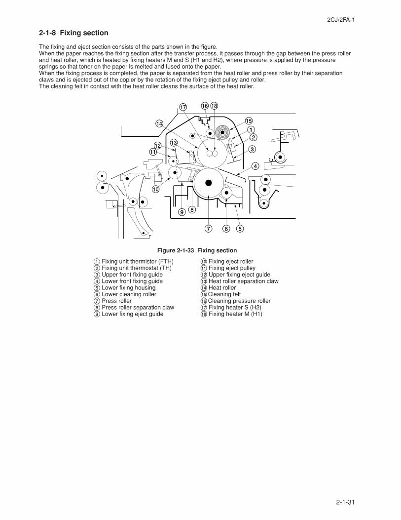
2CJ/2FA-1
2-1-31
2-1-8 Fixing section
The fixing and eject section consists of the parts shown in the figure.When the paper reaches the fixing section after the transfer process, it passes through the gap between the press rollerand heat roller, which is heated by fixing heaters M and S (H1 and H2), where pressure is applied by the pressuresprings so that toner on the paper is melted and fused onto the paper.When the fixing process is completed, the paper is separated from the heat roller and press roller by their separationclaws and is ejected out of the copier by the rotation of the fixing eject pulley and roller.The cleaning felt in contact with the heat roller cleans the surface of the heat roller.
%12
3
4
567
89
0
!@ #
$
& *^
Figure 2-1-33 Fixing section
1 Fixing unit thermistor (FTH)2 Fixing unit thermostat (TH)3 Upper front fixing guide4 Lower front fixing guide5 Lower fixing housing6 Lower cleaning roller7 Press roller8 Press roller separation claw9 Lower fixing eject guide
0 Fixing eject roller! Fixing eject pulley@ Upper fixing eject guide# Heat roller separation claw$ Heat roller%Cleaning felt^Cleaning pressure roller& Fixing heater S (H2)* Fixing heater M (H1)
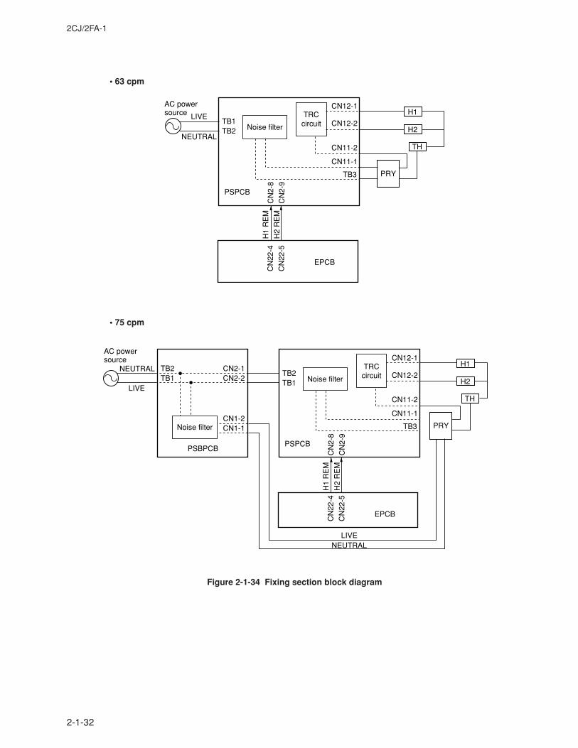
2CJ/2FA-1
2-1-32
Figure 2-1-34 Fixing section block diagram
AC powersource
Noise filter
TRCcircuit
PSPCB
CN
2-8
CN
2-9
CN
22-4
CN
22-5
CN12-1
CN12-2
CN11-2
CN11-1
TB2TB1
THNEUTRAL
LIVE
PRYTB3
H1
H2
EPCBH
1 R
EM
H2
RE
M
AC powersource
Noise filter
Noise filter
TRCcircuit
PSPCBPSBPCB
CN
2-8
CN
2-9
CN
22-4
CN
22-5
CN12-1
CN12-2
CN11-2
CN11-1
TB1TB2
TB1TB2
CN2-2CN2-1
CN1-1CN1-2
TH
NEUTRAL
LIVE
NEUTRALLIVE
PRYTB3
H1
H2
EPCB
H1
RE
M
H2
RE
M
• 63 cpm
• 75 cpm
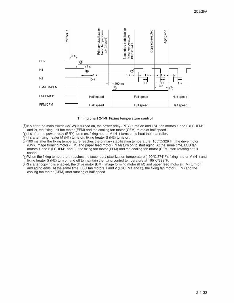
2CJ/2FA
2-1-33
PRY
H1
H2
DM/IFM/PFM
LSUFM1·2
FFM/CFM
MS
W:O
n
2 s
1 s
1 s 1 s 1 s 1 s
1 s 1 s 1 s3 s
100 ms
Half speed
Half speed
Half speed
Half speed
Full speed
Full speed
Prim
ary
stab
iliza
tion
fixin
g te
mpe
ratu
re16
5°C
/329
°F
Sec
onda
ry s
tabi
lizat
ion
fixin
g te
mpe
ratu
re19
0°C
/374
°F
Cop
ying
ena
bled
Agi
ng e
nd
a
b
c
d
e
f
Timing chart 2-1-9 Fixing temperature control
a2 s after the main switch (MSW) is turned on, the power relay (PRY) turns on and LSU fan motors 1 and 2 (LSUFM1and 2), the fixing unit fan motor (FFM) and the cooling fan motor (CFM) rotate at half speed.
b1 s after the power relay (PRY) turns on, fixing heater M (H1) turns on to heat the heat roller.c1 s after fixing heater M (H1) turns on, fixing heater S (H2) turns on.d100 ms after the fixing temperature reaches the primary stabilization temperature (165°C/329°F), the drive motor
(DM), image forming motor (IFM) and paper feed motor (PFM) turn on to start aging. At the same time, LSU fanmotors 1 and 2 (LSUFM1 and 2), the fixing fan motor (FFM) and the cooling fan motor (CFM) start rotating at fullspeed.
eWhen the fixing temperature reaches the secondary stabilization temperature (190°C/374°F), fixing heater M (H1) andfixing heater S (H2) turn on and off to maintain the fixing control temperature at 195°C/383°F.
f3 s after copying is enabled, the drive motor (DM), image forming motor (IFM) and paper feed motor (PFM) turn off,and aging ends. At the same time, LSU fan motors 1 and 2 (LSUFM1 and 2), the fixing fan motor (FFM) and thecooling fan motor (CFM) start rotating at half speed.
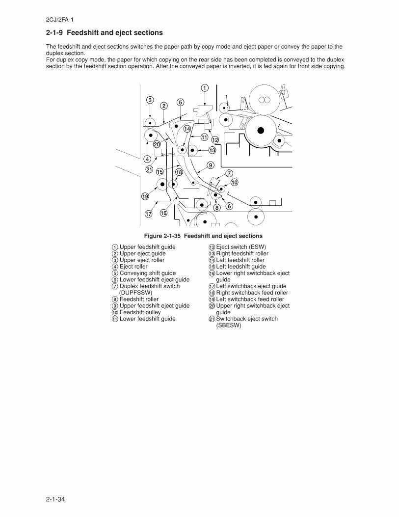
2CJ/2FA-1
2-1-34
2-1-9 Feedshift and eject sections
The feedshift and eject sections switches the paper path by copy mode and eject paper or convey the paper to theduplex section.For duplex copy mode, the paper for which copying on the rear side has been completed is conveyed to the duplexsection by the feedshift section operation. After the conveyed paper is inverted, it is fed again for front side copying.
1
523
4
)
⁄ %
(
& ^
*9
#
!$
@
8 6
07
Figure 2-1-35 Feedshift and eject sections
1 Upper feedshift guide2 Upper eject guide3 Upper eject roller4 Eject roller5 Conveying shift guide6 Lower feedshift eject guide7 Duplex feedshift switch
(DUPFSSW)8 Feedshift roller9 Upper feedshift eject guide0 Feedshift pulley! Lower feedshift guide
@Eject switch (ESW)#Right feedshift roller$Left feedshift roller%Left feedshift guide^Lower right switchback eject
guide&Left switchback eject guide*Right switchback feed roller(Left switchback feed roller)Upper right switchback eject
guide⁄Switchback eject switch
(SBESW)
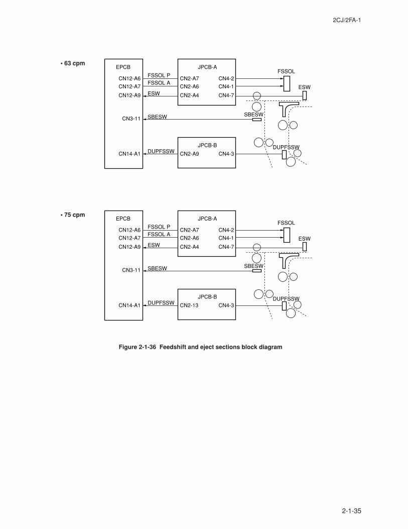
2CJ/2FA-1
2-1-35
Figure 2-1-36 Feedshift and eject sections block diagram
EPCB JPCB-A
JPCB-B
CN12-A6
CN12-A7
CN3-11
CN12-A9
CN14-A1
CN4-2
CN4-1
CN4-7
CN4-3
CN2-A7
CN2-A6
CN2-A4
CN2-A9
FSSOL PFSSOL
ESWESW
FSSOL A
SBESWSBESW
DUPFSSWDUPFSSW
EPCB JPCB-A
JPCB-B
CN12-A6
CN12-A7
CN3-11
CN12-A9
CN14-A1
CN4-2
CN4-1
CN4-7
CN4-3
CN2-A7
CN2-A6
CN2-A4
CN2-13
FSSOL PFSSOL
ESWESW
FSSOL A
SBESWSBESW
DUPFSSWDUPFSSW
• 63 cpm
• 75 cpm
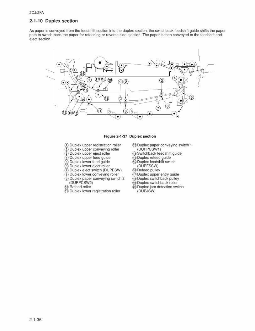
2CJ/2FA
2-1-36
2-1-10 Duplex section
As paper is conveyed from the feedshift section into the duplex section, the switchback feedshift guide shifts the paperpath to switch-back the paper for refeeding or reverse side ejection. The paper is then conveyed to the feedshift andeject section.
1
^
$29 3 4
5
6780# @ !
(
& * )
%
Figure 2-1-37 Duplex section
1 Duplex upper registration roller2 Duplex upper conveying roller3 Duplex upper eject roller4 Duplex upper feed guide5 Duplex lower feed guide6 Duplex lower eject roller7 Duplex eject switch (DUPESW)8 Duplex lower conveying roller9 Duplex paper conveying switch 2
(DUPPCSW2)0 Refeed roller! Duplex lower registration roller
@Duplex paper conveying switch 1(DUPPCSW1)
#Switchback feedshift guide$Duplex refeed guide%Duplex feedshift switch
(DUPFSSW)^Refeed pulley&Duplex upper entry guide*Duplex switchback pulley(Duplex switchback roller)Duplex jam detection switch
(DUPJSW)
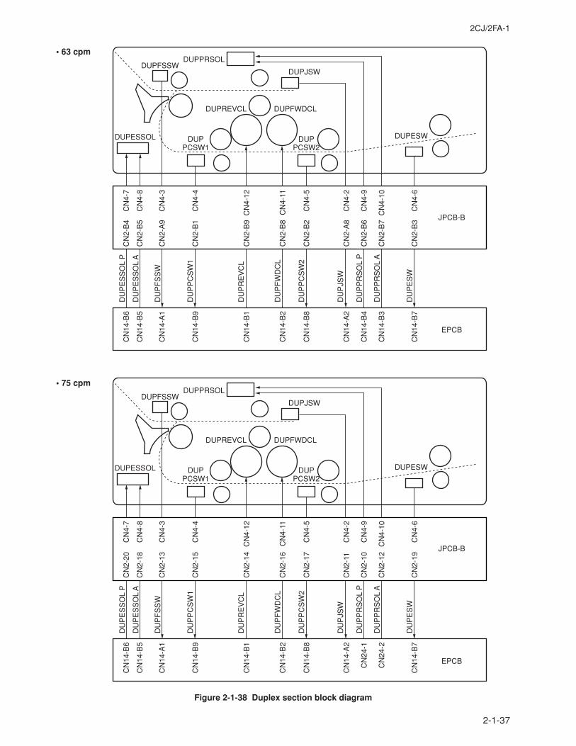
2CJ/2FA-1
2-1-37
Figure 2-1-38 Duplex section block diagram
CN
14-B
6
CN
14-B
5
DU
PE
SS
OL
P
DU
PE
SS
OL
A
CN
14-A
1
CN
14-B
9
CN
14-B
1
CN
14-B
2
CN
14-B
8
CN
14-A
2
DU
PP
RS
OL
P
DU
PP
RS
OL
A
CN
14-B
7
CN
4-7
CN
4-8
CN
4-3
CN
4-4
CN
4-12
CN
4-11
CN
4-5
CN
4-2
CN
4-9
CN
4-10
CN
4-6
DUPESSOL
DUPFSSW
DU
PF
SS
W
DUPPCSW1
DU
PP
CS
W1
DUPPCSW2
DU
PP
CS
W2
DUPREVCL
DU
PR
EV
CL
DUPFWDCL
DU
PF
WD
CL
DUPESW
DU
PE
SW
DUPPRSOL
DUPJSW
DU
PJS
WEPCB
JPCB-B
CN
14-B
4
CN
14-B
3
CN
2-B
4
CN
2-B
5
CN
2-A
9
CN
2-B
1
CN
2-B
9
CN
2-B
8
CN
2-B
2
CN
2-A
8
CN
2-B
6
CN
2-B
7
CN
2-B
3
CN
14-B
6
CN
14-B
5
DU
PE
SS
OL
P
DU
PE
SS
OL
A
CN
14-A
1
CN
14-B
9
CN
14-B
1
CN
14-B
2
CN
14-B
8
CN
14-A
2
DU
PP
RS
OL
P
DU
PP
RS
OL
A
CN
14-B
7
CN
4-7
CN
4-8
CN
4-3
CN
4-4
CN
4-12
CN
4-11
CN
4-5
CN
4-2
CN
4-9
CN
4-10
CN
4-6
DUPESSOL
DUPFSSW
DU
PF
SS
W
DUPPCSW1
DU
PP
CS
W1
DUPPCSW2
DU
PP
CS
W2
DUPREVCL
DU
PR
EV
CL
DUPFWDCL
DU
PF
WD
CL
DUPESW
DU
PE
SW
DUPPRSOL
DUPJSW
DU
PJS
W
EPCB
JPCB-B
CN
24-1
CN
24-2
CN
2-20
CN
2-18
CN
2-13
CN
2-15
CN
2-14
CN
2-16
CN
2-17
CN
2-11
CN
2-10
CN
2-12
CN
2-19
• 63 cpm
• 75 cpm
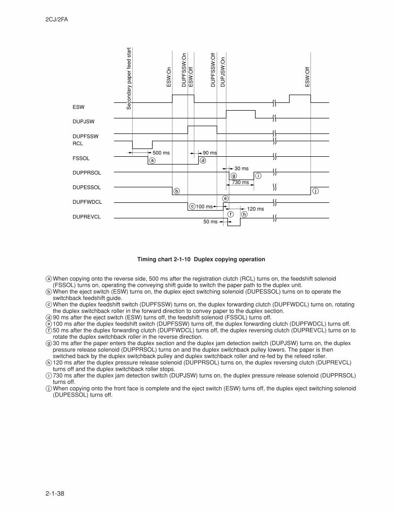
2CJ/2FA
2-1-38
ESW
DUPJSW
DUPFSSWRCL
FSSOL
DUPPRSOL
DUPESSOL
DUPFWDCL
DUPREVCL
ES
W:O
n
ES
W:O
ff
DU
PF
SS
W:O
n
DU
PF
SS
W:O
ff
DU
PJS
W:O
n
ES
W:O
ff
500 ms 90 ms
30 ms
730 ms
100 ms
50 ms
120 ms
Sec
onda
ry p
aper
feed
sta
rt
a d
b j
ce
f h
g i
Timing chart 2-1-10 Duplex copying operation
aWhen copying onto the reverse side, 500 ms after the registration clutch (RCL) turns on, the feedshift solenoid(FSSOL) turns on, operating the conveying shift guide to switch the paper path to the duplex unit.
bWhen the eject switch (ESW) turns on, the duplex eject switching solenoid (DUPESSOL) turns on to operate theswitchback feedshift guide.
cWhen the duplex feedshift switch (DUPFSSW) turns on, the duplex forwarding clutch (DUPFWDCL) turns on, rotatingthe duplex switchback roller in the forward direction to convey paper to the duplex section.
d90 ms after the eject switch (ESW) turns off, the feedshift solenoid (FSSOL) turns off.e100 ms after the duplex feedshift switch (DUPFSSW) turns off, the duplex forwarding clutch (DUPFWDCL) turns off.f50 ms after the duplex forwarding clutch (DUPFWDCL) turns off, the duplex reversing clutch (DUPREVCL) turns on to
rotate the duplex switchback roller in the reverse direction.g30 ms after the paper enters the duplex section and the duplex jam detection switch (DUPJSW) turns on, the duplex
pressure release solenoid (DUPPRSOL) turns on and the duplex switchback pulley lowers. The paper is thenswitched back by the duplex switchback pulley and duplex switchback roller and re-fed by the refeed roller.
h120 ms after the duplex pressure release solenoid (DUPPRSOL) turns on, the duplex reversing clutch (DUPREVCL)turns off and the duplex switchback roller stops.
i730 ms after the duplex jam detection switch (DUPJSW) turns on, the duplex pressure release solenoid (DUPPRSOL)turns off.
jWhen copying onto the front face is complete and the eject switch (ESW) turns off, the duplex eject switching solenoid(DUPESSOL) turns off.
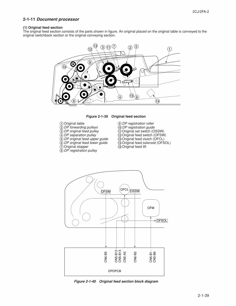
2CJ/2FA-2
2-1-39
2-1-11 Document processor
(1) Original feed sectionThe original feed section consists of the parts shown in figure. An original placed on the original table is conveyed to theoriginal switchback section or the original conveying section.
1527!3#
@
08
94 %6
$
Figure 2-1-39 Original feed section
OFSW
OFSOL
OFCL
OFM
DPDPCB
CN
6-B
5
CN
5-B
12 -
C
N5-
B13
CN
5-A
5
CN
6-B
2
CN
5-B
1 -
CN
5-B
6
OSSW
Figure 2-1-40 Original feed section block diagram
1Original table2DP forwarding pulleys3DP original feed pulley4DP separation pulley5DP original feed upper guide6DP original feed lower guide7Original stopper8DP registration pulley
9DP registration roller0DP registration guide!Original set switch (OSSW)@Original feed switch (OFSW)#Original feed clutch (OFCL)$Original feed solenoid (OFSOL)%Original feed lift
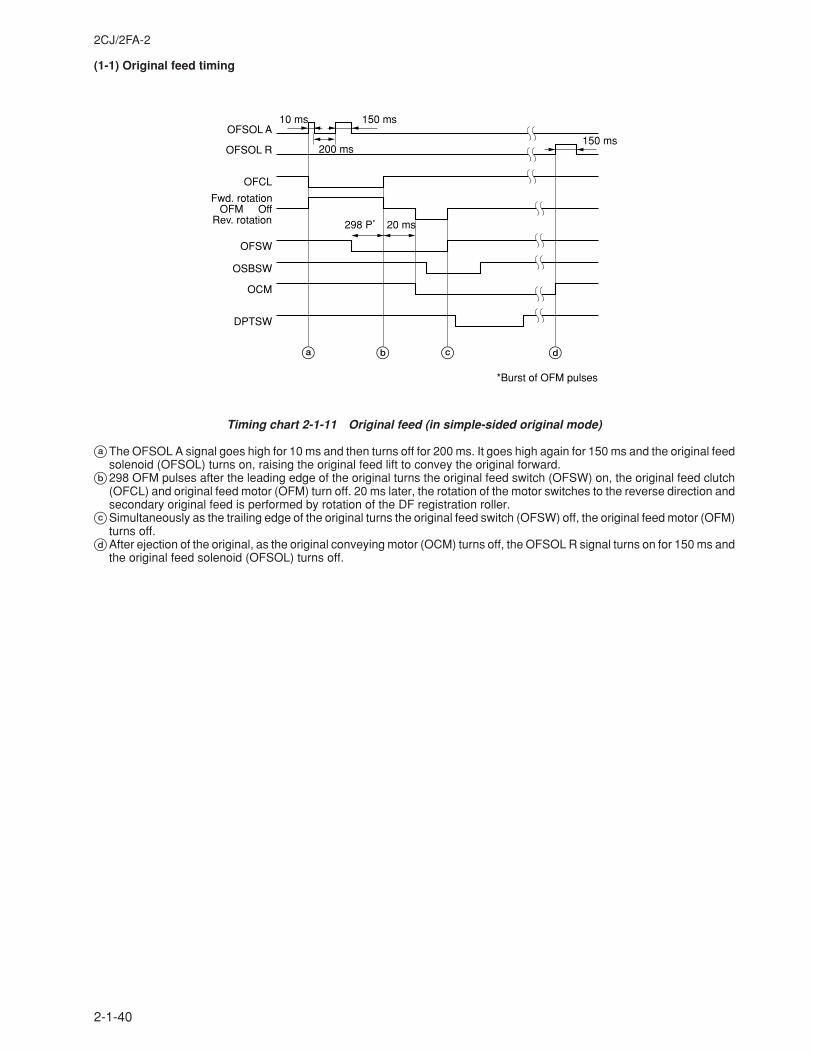
2CJ/2FA-2
2-1-40
(1-1) Original feed timing
OFSOL A
OFSOL R
OFCL
OFSW
OSBSW
OCM
DPTSW
OffOFM
10 ms 150 ms
200 ms150 ms
298 P* 20 ms
b c da
Fwd. rotation
Rev. rotation
*Burst of OFM pulses
Timing chart 2-1-11 Original feed (in simple-sided original mode)
aThe OFSOL A signal goes high for 10 ms and then turns off for 200 ms. It goes high again for 150 ms and the original feedsolenoid (OFSOL) turns on, raising the original feed lift to convey the original forward.
b298 OFM pulses after the leading edge of the original turns the original feed switch (OFSW) on, the original feed clutch(OFCL) and original feed motor (OFM) turn off. 20 ms later, the rotation of the motor switches to the reverse direction andsecondary original feed is performed by rotation of the DF registration roller.
cSimultaneously as the trailing edge of the original turns the original feed switch (OFSW) off, the original feed motor (OFM)turns off.
dAfter ejection of the original, as the original conveying motor (OCM) turns off, the OFSOL R signal turns on for 150 ms andthe original feed solenoid (OFSOL) turns off.
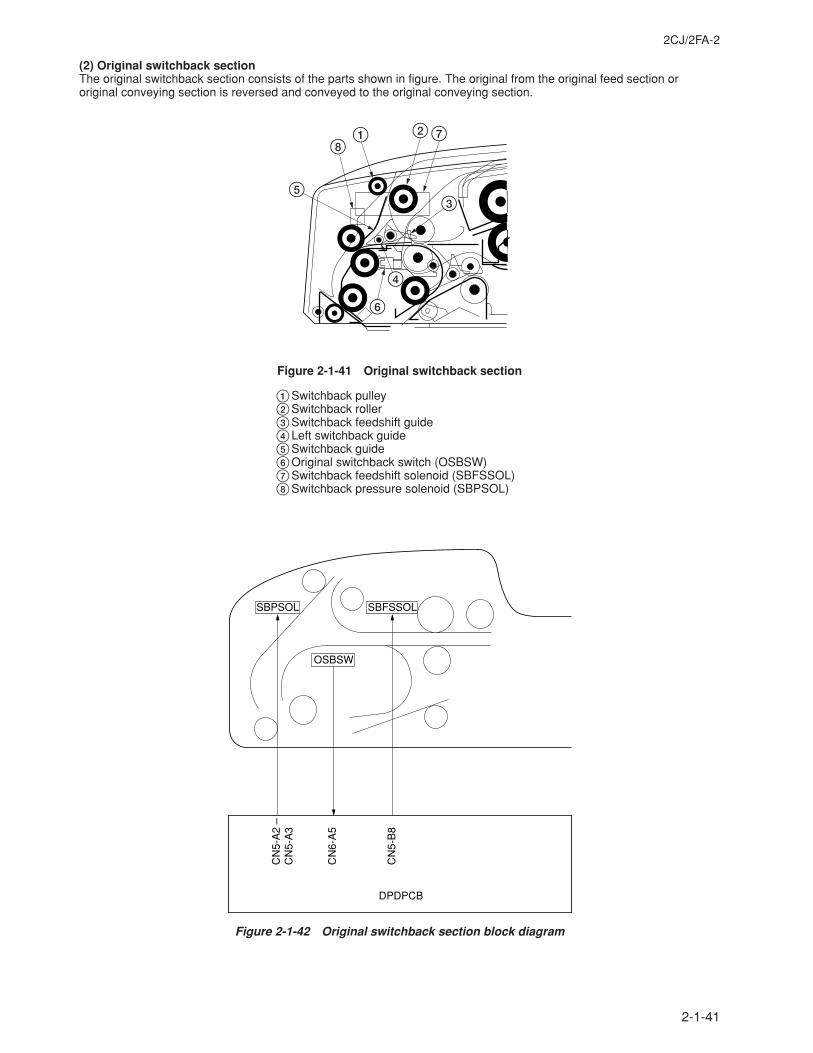
2CJ/2FA-2
2-1-41
(2) Original switchback sectionThe original switchback section consists of the parts shown in figure. The original from the original feed section ororiginal conveying section is reversed and conveyed to the original conveying section.
7218
5
6
4
3
Figure 2-1-41 Original switchback section
1Switchback pulley2Switchback roller3Switchback feedshift guide4Left switchback guide5Switchback guide6Original switchback switch (OSBSW)7Switchback feedshift solenoid (SBFSSOL)8Switchback pressure solenoid (SBPSOL)
DPDPCB
CN
6-A
5
CN
5-B
8
CN
5-A
2 –
CN
5-A
3
OSBSW
SBPSOL SBFSSOL
Figure 2-1-42 Original switchback section block diagram
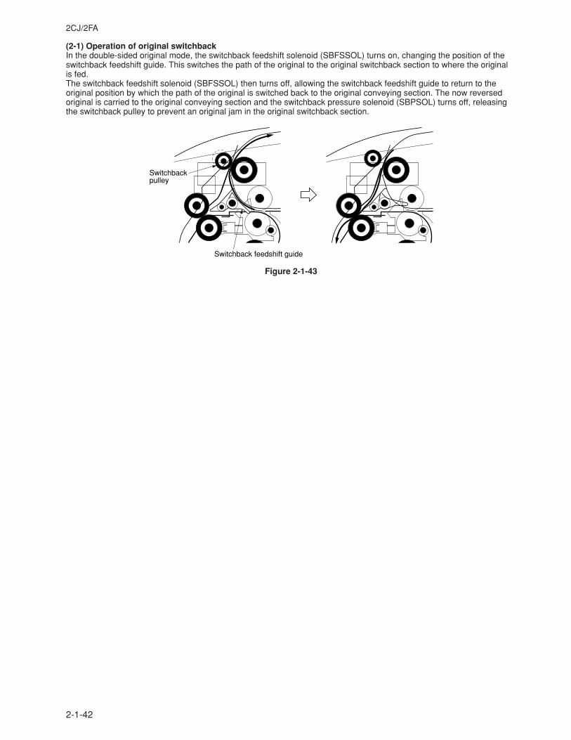
2CJ/2FA
2-1-42
(2-1) Operation of original switchbackIn the double-sided original mode, the switchback feedshift solenoid (SBFSSOL) turns on, changing the position of theswitchback feedshift guide. This switches the path of the original to the original switchback section to where the originalis fed.The switchback feedshift solenoid (SBFSSOL) then turns off, allowing the switchback feedshift guide to return to theoriginal position by which the path of the original is switched back to the original conveying section. The now reversedoriginal is carried to the original conveying section and the switchback pressure solenoid (SBPSOL) turns off, releasingthe switchback pulley to prevent an original jam in the original switchback section.
Switchbackpulley
Switchback feedshift guide
Figure 2-1-43
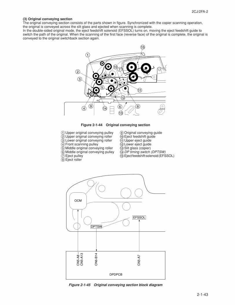
2CJ/2FA-2
2-1-43
(3) Original conveying sectionThe original conveying section consists of the parts shown in figure. Synchronized with the copier scanning operation,the original is conveyed across the slit glass and ejected when scanning is complete.In the double-sided original mode, the eject feedshift solenoid (EFSSOL) turns on, moving the eject feedshift guide toswitch the path of the original. When the scanning of the first face (reverse face) of the original is complete, the original isconveyed to the original switchback section again.
%
1
4 9 $
5
6
#
@
8
!
70
2
3
Figure 2-1-44 Original conveying section
1Upper original conveying pulley2Upper original conveying roller3Lower original conveying roller4Front scanning pulley5Middle original conveying roller6Middle original conveying pulley7Eject pulley8Eject roller
9Original conveying guide0Eject feedshift guide!Upper eject guide@Lower eject guide#Slit glass (copier)$DP timing switch (DPTSW)%Eject feedshift solenoid (EFSSOL)
DPTSW
DPDPCB
CN
6-B
14
CN
5-A
7
CN
5-A
8 –
CN
5-A
13
EFSSOL
OCM
Figure 2-1-45 Original conveying section block diagram
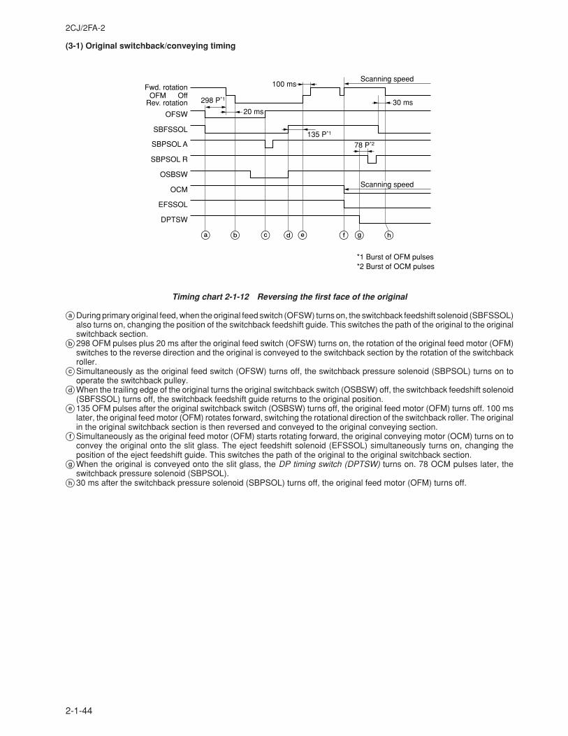
2CJ/2FA-2
2-1-44
(3-1) Original switchback/conveying timing
Fwd. rotationOff
298 P*1
100 ms
30 ms
78 P*2
135 P*1
OFMRev. rotation
OFSW
SBFSSOL
SBPSOL R
SBPSOL A
OSBSW
OCM
EFSSOL
DPTSW
20 ms
Scanning speed
Scanning speed
*1 Burst of OFM pulses*2 Burst of OCM pulses
a b edc f g h
Timing chart 2-1-12 Reversing the first face of the original
aDuring primary original feed, when the original feed switch (OFSW) turns on, the switchback feedshift solenoid (SBFSSOL)also turns on, changing the position of the switchback feedshift guide. This switches the path of the original to the originalswitchback section.
b298 OFM pulses plus 20 ms after the original feed switch (OFSW) turns on, the rotation of the original feed motor (OFM)switches to the reverse direction and the original is conveyed to the switchback section by the rotation of the switchbackroller.
cSimultaneously as the original feed switch (OFSW) turns off, the switchback pressure solenoid (SBPSOL) turns on tooperate the switchback pulley.
dWhen the trailing edge of the original turns the original switchback switch (OSBSW) off, the switchback feedshift solenoid(SBFSSOL) turns off, the switchback feedshift guide returns to the original position.
e135 OFM pulses after the original switchback switch (OSBSW) turns off, the original feed motor (OFM) turns off. 100 mslater, the original feed motor (OFM) rotates forward, switching the rotational direction of the switchback roller. The originalin the original switchback section is then reversed and conveyed to the original conveying section.
fSimultaneously as the original feed motor (OFM) starts rotating forward, the original conveying motor (OCM) turns on toconvey the original onto the slit glass. The eject feedshift solenoid (EFSSOL) simultaneously turns on, changing theposition of the eject feedshift guide. This switches the path of the original to the original switchback section.
gWhen the original is conveyed onto the slit glass, the DP timing switch (DPTSW) turns on. 78 OCM pulses later, theswitchback pressure solenoid (SBPSOL).
h30 ms after the switchback pressure solenoid (SBPSOL) turns off, the original feed motor (OFM) turns off.
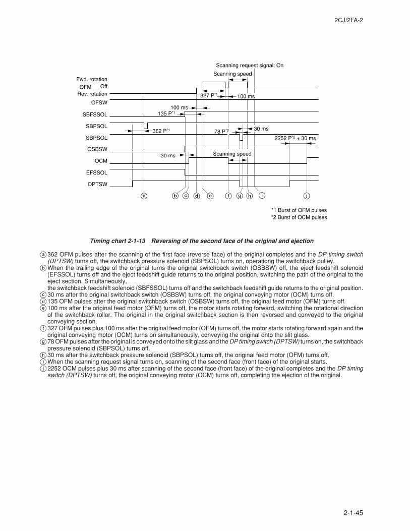
2CJ/2FA-2
2-1-45
Fwd. rotationOff
362 P*1
2252 P*2 + 30 ms
100 ms
30 ms
135 P*1
OFMRev. rotation
OFSW
SBFSSOL
SBPSOL
SBPSOL
OSBSW
OCM
EFSSOL
DPTSW
78 P*2
327 P*1
Scanning request signal: On
Scanning speed
Scanning speed
100 ms
30 ms
*1 Burst of OFM pulses*2 Burst of OCM pulses
a b edc f hg i j
Timing chart 2-1-13 Reversing of the second face of the original and ejection
a362 OFM pulses after the scanning of the first face (reverse face) of the original completes and the DP timing switch(DPTSW) turns off, the switchback pressure solenoid (SBPSOL) turns on, operationg the switchback pulley.
bWhen the trailing edge of the original turns the original switchback switch (OSBSW) off, the eject feedshift solenoid(EFSSOL) turns off and the eject feedshift guide returns to the original position, switching the path of the original to theeject section. Simultaneously,the switchback feedshift solenoid (SBFSSOL) turns off and the switchback feedshift guide returns to the original position.
c30 ms after the original switchback switch (OSBSW) turns off, the original conveying motor (OCM) turns off.d135 OFM pulses after the original switchback switch (OSBSW) turns off, the original feed motor (OFM) turns off.e100 ms after the original feed motor (OFM) turns off, the motor starts rotating forward, switching the rotational direction
of the switchback roller. The original in the original switchback section is then reversed and conveyed to the originalconveying section.
f327 OFM pulses plus 100 ms after the original feed motor (OFM) turns off, the motor starts rotating forward again and theoriginal conveying motor (OCM) turns on simultaneously, conveying the original onto the slit glass.
g78 OFM pulses after the original is conveyed onto the slit glass and the DP timing switch (DPTSW) turns on, the switchbackpressure solenoid (SBPSOL) turns off.
h30 ms after the switchback pressure solenoid (SBPSOL) turns off, the original feed motor (OFM) turns off.iWhen the scanning request signal turns on, scanning of the second face (front face) of the original starts.j2252 OCM pulses plus 30 ms after scanning of the second face (front face) of the original completes and the DP timing
switch (DPTSW) turns off, the original conveying motor (OCM) turns off, completing the ejection of the original.
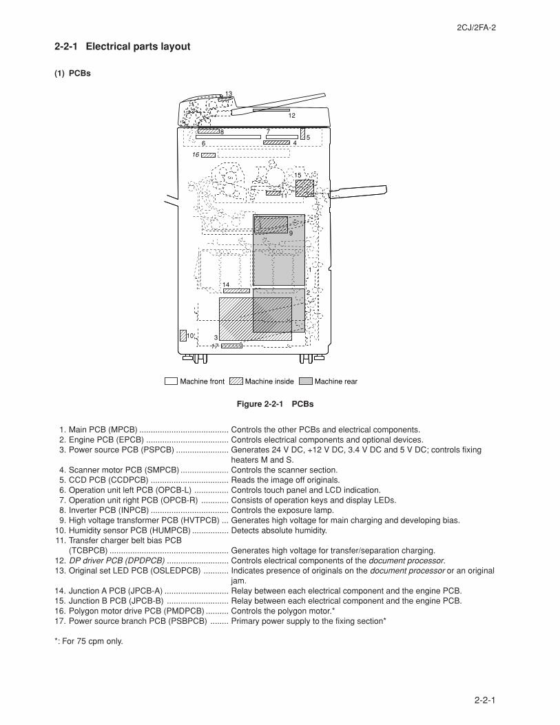
2CJ/2FA-2
2-2-1
2-2-1 Electrical parts layout
(1) PCBs
12
11
16
17
15
8
65
7
4
9
14
1
2
10 3
Machine front Machine inside Machine rear
13
Figure 2-2-1 PCBs
1. Main PCB (MPCB) ....................................... Controls the other PCBs and electrical components.2. Engine PCB (EPCB) .................................... Controls electrical components and optional devices.3. Power source PCB (PSPCB) ....................... Generates 24 V DC, +12 V DC, 3.4 V DC and 5 V DC; controls fixing
heaters M and S.4. Scanner motor PCB (SMPCB) ..................... Controls the scanner section.5. CCD PCB (CCDPCB) .................................. Reads the image off originals.6. Operation unit left PCB (OPCB-L) ............... Controls touch panel and LCD indication.7. Operation unit right PCB (OPCB-R) ............ Consists of operation keys and display LEDs.8. Inverter PCB (INPCB) .................................. Controls the exposure lamp.9. High voltage transformer PCB (HVTPCB) ... Generates high voltage for main charging and developing bias.
10. Humidity sensor PCB (HUMPCB) ................ Detects absolute humidity.11. Transfer charger belt bias PCB
(TCBPCB) .................................................... Generates high voltage for transfer/separation charging.12. DP driver PCB (DPDPCB) ........................... Controls electrical components of the document processor.13. Original set LED PCB (OSLEDPCB) ........... Indicates presence of originals on the document processor or an original
jam.14. Junction A PCB (JPCB-A) ............................ Relay between each electrical component and the engine PCB.15. Junction B PCB (JPCB-B) ........................... Relay between each electrical component and the engine PCB.16. Polygon motor drive PCB (PMDPCB) .......... Controls the polygon motor.*17. Power source branch PCB (PSBPCB) ........ Primary power supply to the fixing section*
*: For 75 cpm only.
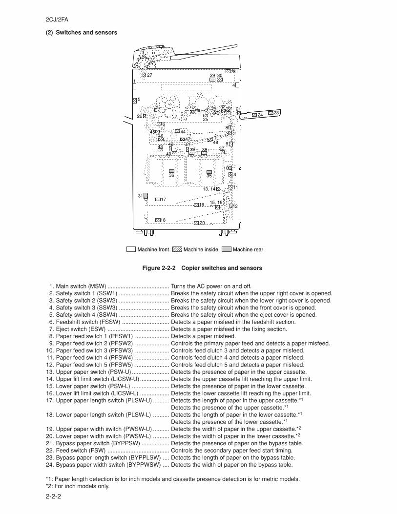
2CJ/2FA
2-2-2
27 29 3028
41
5
7
6
33
25
34 32 22 2124 23
82
948373839
4147
444546
42
40
43
103
1113, 14
1215, 1619
17
2018
31
36 35
26
Machine front Machine inside
Machine rear
(2) Switches and sensors
Figure 2-2-2 Copier switches and sensors
1. Main switch (MSW) ...................................... Turns the AC power on and off.2. Safety switch 1 (SSW1) ............................... Breaks the safety circuit when the upper right cover is opened.3. Safety switch 2 (SSW2) ............................... Breaks the safety circuit when the lower right cover is opened.4. Safety switch 3 (SSW3) ............................... Breaks the safety circuit when the front cover is opened.5. Safety switch 4 (SSW4) ............................... Breaks the safety circuit when the eject cover is opened.6. Feedshift switch (FSSW) ............................. Detects a paper misfeed in the feedshift section.7. Eject switch (ESW) ...................................... Detects a paper misfeed in the fixing section.8. Paper feed switch 1 (PFSW1) ..................... Detects a paper misfeed.9. Paper feed switch 2 (PFSW2) ..................... Controls the primary paper feed and detects a paper misfeed.
10. Paper feed switch 3 (PFSW3) ..................... Controls feed clutch 3 and detects a paper misfeed.11. Paper feed switch 4 (PFSW4) ..................... Controls feed clutch 4 and detects a paper misfeed.12. Paper feed switch 5 (PFSW5) ..................... Controls feed clutch 5 and detects a paper misfeed.13. Upper paper switch (PSW-U) ....................... Detects the presence of paper in the upper cassette.14. Upper lift limit switch (LICSW-U) .................. Detects the upper cassette lift reaching the upper limit.15. Lower paper switch (PSW-L) ....................... Detects the presence of paper in the lower cassette.16. Lower lift limit switch (LICSW-L) .................. Detects the lower cassette lift reaching the upper limit.17. Upper paper length switch (PLSW-U) .......... Detects the length of paper in the upper cassette.*1
Detects the presence of the upper cassette.*1
18. Lower paper length switch (PLSW-L) .......... Detects the length of paper in the lower cassette.*1
Detects the presence of the lower cassette.*1
19. Upper paper width switch (PWSW-U) .......... Detects the width of paper in the upper cassette.*2
20. Lower paper width switch (PWSW-L) .......... Detects the width of paper in the lower cassette.*2
21. Bypass paper switch (BYPPSW) ................. Detects the presence of paper on the bypass table.22. Feed switch (FSW) ...................................... Controls the secondary paper feed start timing.23. Bypass paper length switch (BYPPLSW) .... Detects the length of paper on the bypass table.24. Bypass paper width switch (BYPPWSW) .... Detects the width of paper on the bypass table.
*1: Paper length detection is for inch models and cassette presence detection is for metric models.*2: For inch models only.
2CJ/2FA
2-2-3
25. Transfer charger belt detection switch(TCBDSW) ................................................... Detects the position of the transfer charger belt.
26. Switchback eject switch (SBESW) ............... Detects a paper misfeed in the switchback eject section.27. Scanner home position switch (SHPSW) .... Detects the optical system in the home position.28. Original detection switch (ODSW) ............... Operates the original size detection sensors.29. Original size detection sensor 1 (OSD1) ..... Detects the size of the original.30. Original size detection sensor 2 (OSD2) ..... Detects the size of the original.*31. Waste toner detection switch (WTDSW) ...... Detects the weight of the waste toner box.32. Toner sensor (TNS) ..................................... Detects the toner density in the developing section.33. Toner level sensor (TLDS) ........................... Detects the toner level in the toner hopper.34. Registration switch (RSW) ........................... Controls the secondary paper feed stop timing.35. Large paper deck paper level detection
sensor 1 (LPDPLDSENS1) .......................... Detects the paper level in the right large paper deck.36. Large paper deck paper level detection
sensor 2 (LPDPLDSENS2) .......................... Detects the paper level in the left large paper deck.37. Large paper deck paper path sensor 1
(LPDPPSENS1) ........................................... Detects a paper misfeed and the presence of paper on the lift of thelarge paper deck.
38. Large paper deck paper path sensor 2(LPDPPSENS2) ........................................... Detects a paper misfeed and the presence of paper on the lift of the
large paper deck.39. Large paper deck paper path sensor 3
(LPDPPSENS3) ........................................... Detects a paper misfeed and the presence of paper on the lift of thelarge paper deck.
40. Large paper deck paper empty sensor(LPDPESENS) ............................................. Detects the presence of paper in the left large paper deck.
41. Large paper deck level switch 1(LPDLSW1) .................................................. Detects the stop position of the right large paper deck lift.
42. Large paper deck level switch 2(LPDLSW2) .................................................. Detects the stop position of the left large paper deck lift.
43. Large paper deck open safety switch(LPDOSSW) ................................................ Detects when the large paper deck is opened or closed.
44. Duplex jam detection switch (DUPJSW) ...... Detects a paper misfeed.45. Duplex feedshift switch (DUPFSSW) ........... Detects a paper misfeed in the duplex feedshift section.46. Duplex paper conveying switch 1
(DUPPCSW1) .............................................. Detects a paper misfeed in the duplex paper conveying section.47. Duplex paper conveying switch 2
(DUPPCSW2) .............................................. Detects a paper misfeed in the duplex paper conveying section.48. Duplex eject switch (DUPESW) ................... Detects a paper misfeed in the duplex eject section.
* For inch models only.
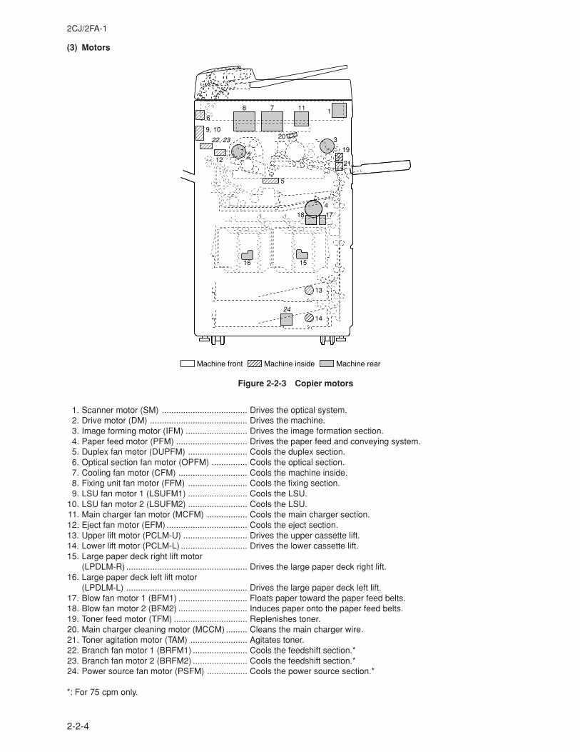
2CJ/2FA-1
2-2-4
6
9, 10
22, 23
8 7 11
24
1
20 3
19
212
5
418 17
1516
13
14
Machine front Machine inside Machine rear
12
(3) Motors
Figure 2-2-3 Copier motors
1. Scanner motor (SM) .................................... Drives the optical system.2. Drive motor (DM) ......................................... Drives the machine.3. Image forming motor (IFM) .......................... Drives the image formation section.4. Paper feed motor (PFM) .............................. Drives the paper feed and conveying system.5. Duplex fan motor (DUPFM) ......................... Cools the duplex section.6. Optical section fan motor (OPFM) ............... Cools the optical section.7. Cooling fan motor (CFM) ............................. Cools the machine inside.8. Fixing unit fan motor (FFM) ......................... Cools the fixing section.9. LSU fan motor 1 (LSUFM1) ......................... Cools the LSU.
10. LSU fan motor 2 (LSUFM2) ......................... Cools the LSU.11. Main charger fan motor (MCFM) ................. Cools the main charger section.12. Eject fan motor (EFM) .................................. Cools the eject section.13. Upper lift motor (PCLM-U) ........................... Drives the upper cassette lift.14. Lower lift motor (PCLM-L) ............................ Drives the lower cassette lift.15. Large paper deck right lift motor
(LPDLM-R) ................................................... Drives the large paper deck right lift.16. Large paper deck left lift motor
(LPDLM-L) ................................................... Drives the large paper deck left lift.17. Blow fan motor 1 (BFM1) ............................. Floats paper toward the paper feed belts.18. Blow fan motor 2 (BFM2) ............................. Induces paper onto the paper feed belts.19. Toner feed motor (TFM) ............................... Replenishes toner.20. Main charger cleaning motor (MCCM) ......... Cleans the main charger wire.21. Toner agitation motor (TAM) ........................ Agitates toner.22. Branch fan motor 1 (BRFM1) ....................... Cools the feedshift section.*23. Branch fan motor 2 (BRFM2) ....................... Cools the feedshift section.*24. Power source fan motor (PSFM) ................. Cools the power source section.*
*: For 75 cpm only.
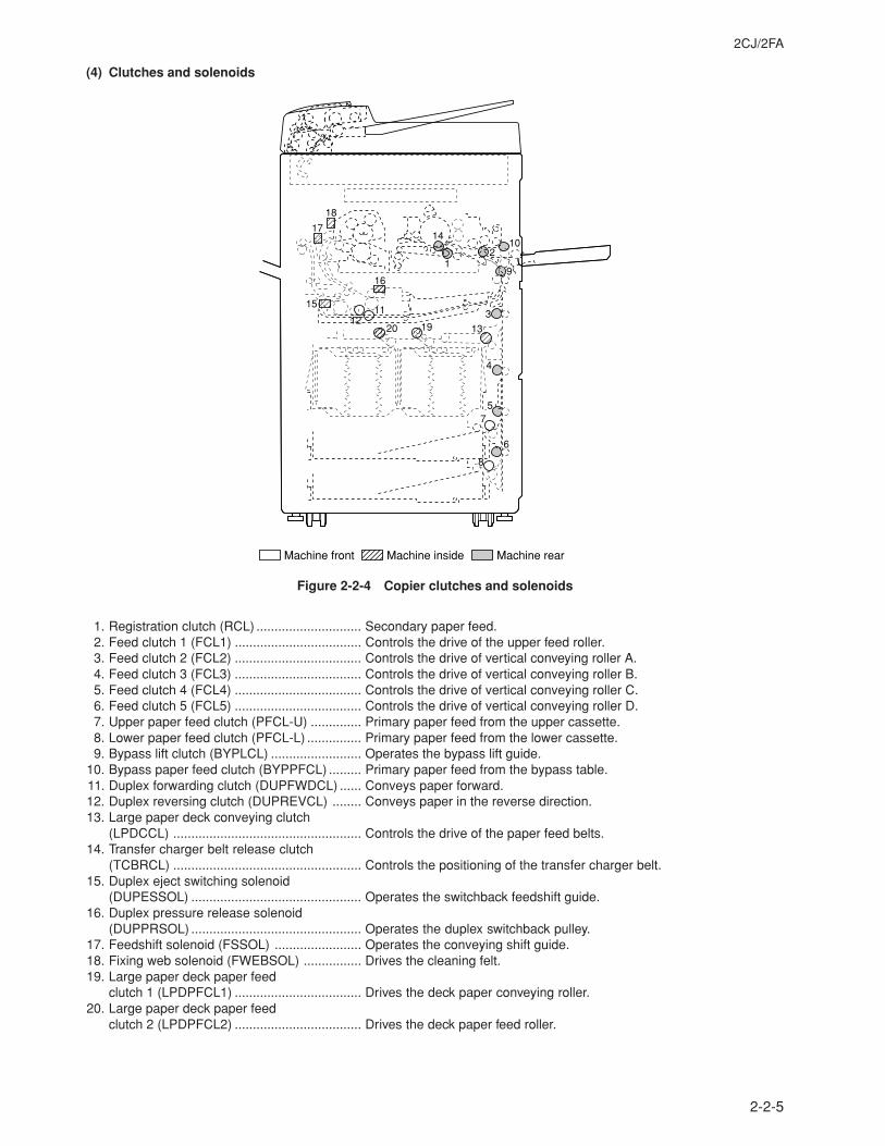
2CJ/2FA
2-2-5
18
1714
12
10
9
3
13
16
15
1211
20 19
4
57
6
8
Machine front Machine inside Machine rear
(4) Clutches and solenoids
Figure 2-2-4 Copier clutches and solenoids
1. Registration clutch (RCL) ............................. Secondary paper feed.2. Feed clutch 1 (FCL1) ................................... Controls the drive of the upper feed roller.3. Feed clutch 2 (FCL2) ................................... Controls the drive of vertical conveying roller A.4. Feed clutch 3 (FCL3) ................................... Controls the drive of vertical conveying roller B.5. Feed clutch 4 (FCL4) ................................... Controls the drive of vertical conveying roller C.6. Feed clutch 5 (FCL5) ................................... Controls the drive of vertical conveying roller D.7. Upper paper feed clutch (PFCL-U) .............. Primary paper feed from the upper cassette.8. Lower paper feed clutch (PFCL-L) ............... Primary paper feed from the lower cassette.9. Bypass lift clutch (BYPLCL) ......................... Operates the bypass lift guide.
10. Bypass paper feed clutch (BYPPFCL) ......... Primary paper feed from the bypass table.11. Duplex forwarding clutch (DUPFWDCL) ...... Conveys paper forward.12. Duplex reversing clutch (DUPREVCL) ........ Conveys paper in the reverse direction.13. Large paper deck conveying clutch
(LPDCCL) .................................................... Controls the drive of the paper feed belts.14. Transfer charger belt release clutch
(TCBRCL) .................................................... Controls the positioning of the transfer charger belt.15. Duplex eject switching solenoid
(DUPESSOL) ............................................... Operates the switchback feedshift guide.16. Duplex pressure release solenoid
(DUPPRSOL) ............................................... Operates the duplex switchback pulley.17. Feedshift solenoid (FSSOL) ........................ Operates the conveying shift guide.18. Fixing web solenoid (FWEBSOL) ................ Drives the cleaning felt.19. Large paper deck paper feed
clutch 1 (LPDPFCL1) ................................... Drives the deck paper conveying roller.20. Large paper deck paper feed
clutch 2 (LPDPFCL2) ................................... Drives the deck paper feed roller.
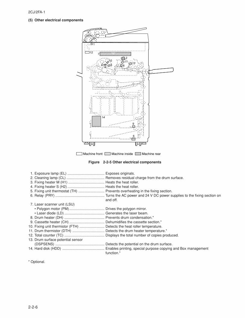
2CJ/2FA-1
2-2-6
1
12 7
43
10
5
211
813
9
6
14
Machine front Machine inside Machine rear
(5) Other electrical components
Figure 2-2-5 Other electrical components
1. Exposure lamp (EL) ..................................... Exposes originals.2. Cleaning lamp (CL) ...................................... Removes residual charge from the drum surface.3. Fixing heater M (H1) .................................... Heats the heat roller.4. Fixing heater S (H2) ..................................... Heats the heat roller.5. Fixing unit thermostat (TH) .......................... Prevents overheating in the fixing section.6. Relay (PRY) ................................................. Turns the AC power and 24 V DC power supplies to the fixing section on
and off.7. Laser scanner unit (LSU)
• Polygon motor (PM) ................................... Drives the polygon mirror.• Laser diode (LD) ........................................ Generates the laser beam.
8. Drum heater (DH) ........................................ Prevents drum condensation.*9. Cassette heater (CH) ................................... Dehumidifies the cassette section.*
10. Fixing unit thermistor (FTH) ......................... Detects the heat roller temperature.11. Drum thermistor (DTH) ................................ Detects the drum heater temperature.*12. Total counter (TC) ........................................ Displays the total number of copies produced.13. Drum surface potential sensor
(DSPSENS) ................................................. Detects the potential on the drum surface.14. Hard disk (HDD) .......................................... Enables printing, special purpose copying and Box management
function.*
* Optional.
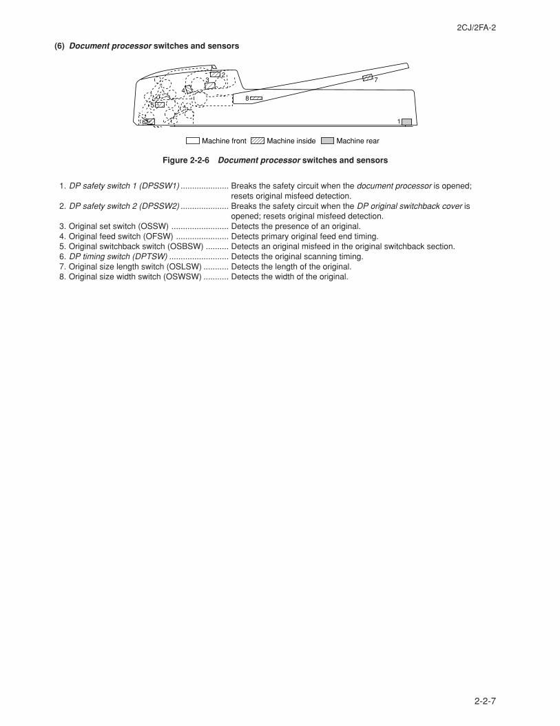
2CJ/2FA-2
2-2-7
y 8
73
5
2
4
16
Machine front Machine inside Machine rear
(6) Document processor switches and sensors
Figure 2-2-6 Document processor switches and sensors
1. DP safety switch 1 (DPSSW1) ..................... Breaks the safety circuit when the document processor is opened;resets original misfeed detection.
2. DP safety switch 2 (DPSSW2) ..................... Breaks the safety circuit when the DP original switchback cover isopened; resets original misfeed detection.
3. Original set switch (OSSW) ......................... Detects the presence of an original.4. Original feed switch (OFSW) ....................... Detects primary original feed end timing.5. Original switchback switch (OSBSW) .......... Detects an original misfeed in the original switchback section.6. DP timing switch (DPTSW) .......................... Detects the original scanning timing.7. Original size length switch (OSLSW) ........... Detects the length of the original.8. Original size width switch (OSWSW) ........... Detects the width of the original.
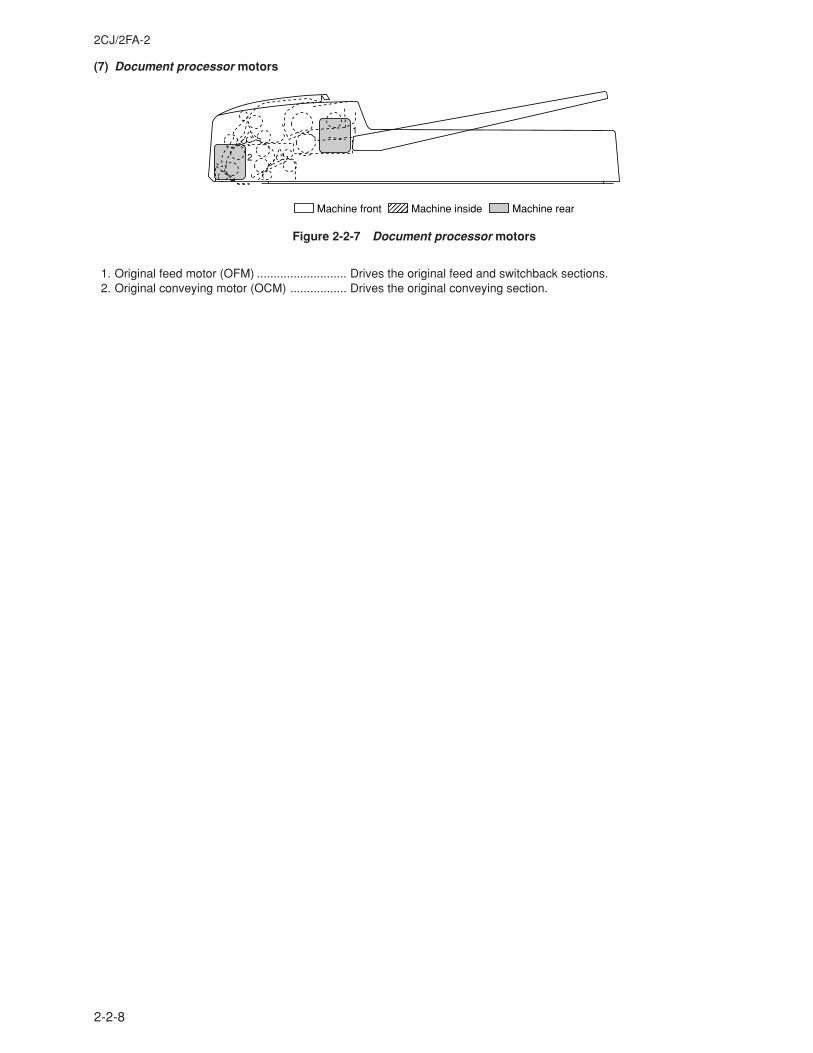
2CJ/2FA-2
2-2-8
2
1
Machine front Machine inside
Machine rear
(7) Document processor motors
Figure 2-2-7 Document processor motors
1. Original feed motor (OFM) ........................... Drives the original feed and switchback sections.2. Original conveying motor (OCM) ................. Drives the original conveying section.
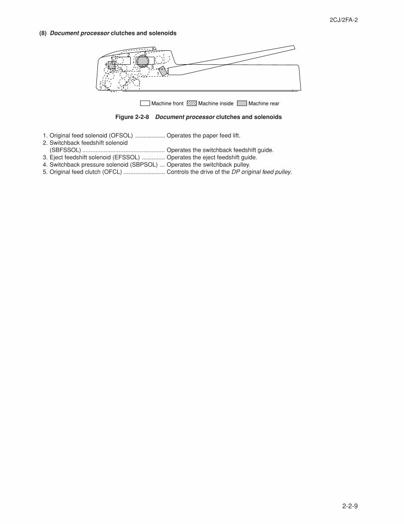
2CJ/2FA-2
2-2-9
5
1
4
2
3
Machine front Machine inside Machine rear
(8) Document processor clutches and solenoids
Figure 2-2-8 Document processor clutches and solenoids
1. Original feed solenoid (OFSOL) .................. Operates the paper feed lift.2. Switchback feedshift solenoid
(SBFSSOL) .................................................. Operates the switchback feedshift guide.3. Eject feedshift solenoid (EFSSOL) .............. Operates the eject feedshift guide.4. Switchback pressure solenoid (SBPSOL) ... Operates the switchback pulley.5. Original feed clutch (OFCL) ......................... Controls the drive of the DP original feed pulley.
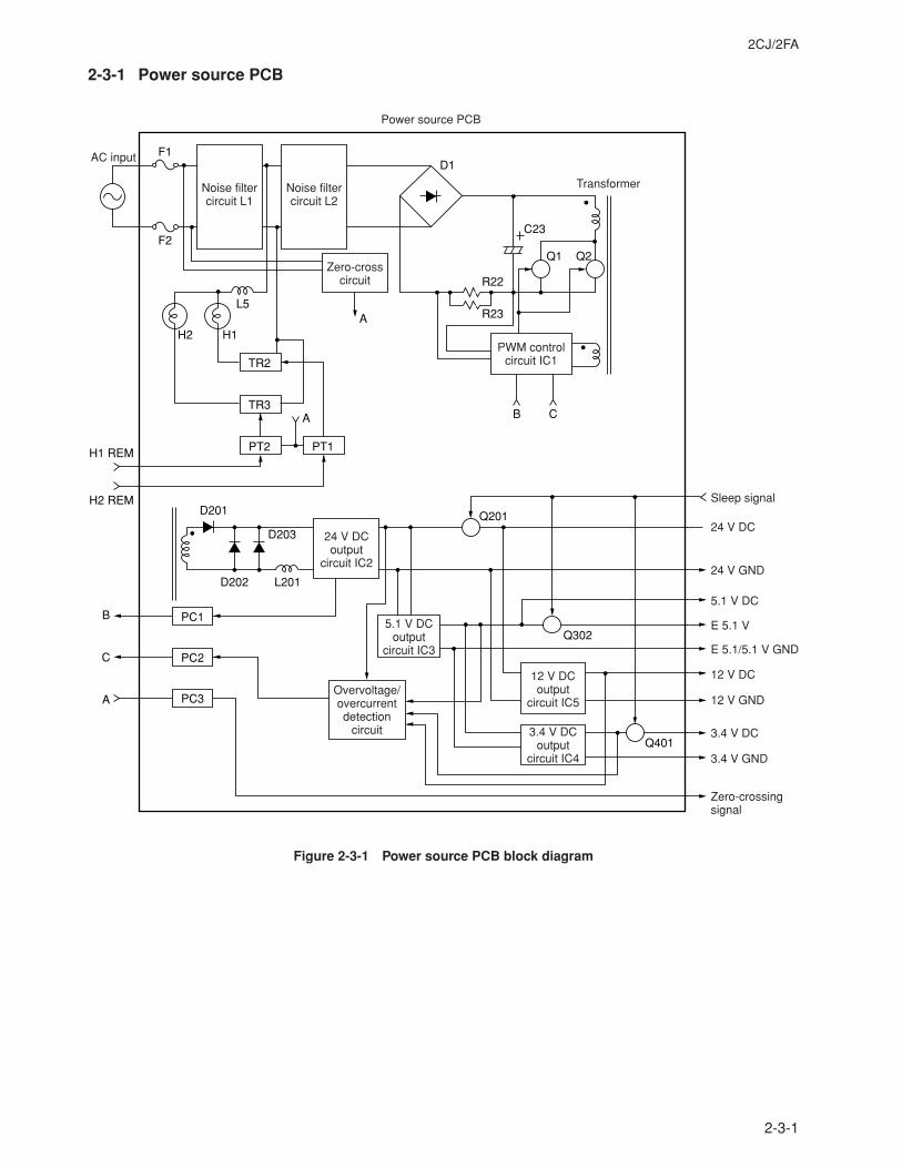
2CJ/2FA
2-3-1
2-3-1 Power source PCB
AC input
Noise filter circuit L1
Noise filter circuit L2
Zero-cross circuit
Power source PCB
24 V DC output
circuit IC2
5.1 V DC output
circuit IC3
Overvoltage/overcurrent detection
circuit
12 V DCoutput
circuit IC5
3.4 V DC output
circuit IC4
Transformer
PWM control circuit IC1
F1D1
C23
R23
R22
F2
L5
H1
Q1 Q2
H1 REM
H2 REM
TR2
TR3
PT2 PT1
PC1
D202 L201
Q201
Q4013.4 V GND
Zero-crossing signal
Sleep signal
E 5.1/5.1 V GND
12 V GND
24 V GND
24 V DC
5.1 V DC
3.4 V DC
12 V DC
E 5.1 VQ302
D203
D201
PC2
PC3
A
B CA
A
C
B
H2
Figure 2-3-1 Power source PCB block diagram
2CJ/2FA
2-3-2
The power source PCB (PSPCB) is a switching regulator which converts an AC input to generate 24 V DC, 5.1 V DC, 3.4 VDC and 12 V DC. It includes the components shown in Figure 2-3-1; noise filter circuits, a rectifier circuit, a PWM controlcircuit, a 24 V DC output circuit, a 5.1 V DC output circuit, a 3.4 V DC output circuit, a 12 V DC output circuit, a fixing heatercontrol circuit, an overvoltage/overcurrent detection circuit.The noise filter circuit, consisting mainly of noise filter circuits L1 and L2 in the power source section and capacitors,attenuates external noise from the AC input and prevents switching noise generated by the power source circuit fromleaving the machine via the AC line. Choke coil L5 prevents the noise generated in the heater circuit when the heater turnson from leaving the machine via the AC line.The rectifier circuit full-wave rectifies the AC input which has passed through the noise filter circuits L1 and L2 using thediode bridge D1.In the PWM control circuit, PWM controller IC1 turns FETs Q1 and Q2 on and off to convert DC voltage full-wave rectified viadiode bridge D1 and smoothed by electrolytic capacitor C23 to a high-frequency current, which is applied to the primary coilof the transformer.The 24 V DC output circuit smoothes the current induced on the secondary coil of the transformer via diodes D201, D202and D203 and smoothing choke coil L201, providing a more stable 24 V DC through 24 V DC control circuit including IC2.It also monitors the 24 V DC output status, which is fed back to PWM controller IC1 in the PWM control circuit viaphotocoupler PC1. PWM controller IC1 controls the switching duty width of switching FETs Q1 and Q2 based on the outputvoltage status, producing a stable 24 V DC output.The 5.1 V DC output circuit receives 24 V DC from the 24 V DC control circuit and outputs a stable 5.1 V DC via DC/DCconverter controller IC3.The 3.4 V DC output circuit receives 5.1 V DC from the 5.1 V DC control circuit and outputs a stable 3.4 V DC via DC/DCconverter controller IC4.The 12 V DC output circuit receives 24 V DC from the 24 V DC control circuit and outputs a stable 12 V DC via DC/DCconverter controller IC5.FETs Q201, Q302 and Q401 turn on/off the output based on the sleep signal they receive from the main PCB (MPCB). In theenergy saving mode, the FETs turn off to cut off the output of 24 V DC and 3.4 V DC, and some outputs of 5.1 V DC. Sincethe 12 V DC output is the input from output-controlling FET Q201, output of 12 V DC also ceases. As a result, all DC outputsexcept some 5.1 V DC outputs are cut off, by which means energy consumption is lowered to the Energy Star accreditationlevel while in the stand-by mode.Abnormal rise of voltage for all DC outputs and overcurrent in 5.1 V DC and 12 V DC outputs are monitored by theovervoltage/overcurrent detection circuit, and if any abnormal rise is detected, alarm signals are fed back to the PWMcontrol circuit IC1 via photocoupler PC2 instantly, by which means power supply is limited to the stand-by level. Overload ofthe 24 V DC output is monitored by resistors R22 and R23 as the total sum of all DC output power. If any abnormal conditionis detected, the power supply is latched off. To recover the power supply, remove the cause of abnormality and turn the ACinput off and back on. Overload of the 3.4 V DC output is monitored by the overcurrent detection function of IC4 of the 3.4 VDC circuit. If any abnormality is detected, only the 3.4 V DC output is shut down, while all other DC outputs remain live.When the abnormal output condition is removed, the 3.4 V DC output returns to the normal output condition.The fixing heater control circuit sends a zero-crossing signal from the zero-crossing circuit via the photocoupler PC3 to themain PCB (MPCB). These signals are in turn converted into signals to control the on/off timing and phases, which are theninput to the power source PCB (PSPCB) as H1 REM and H2 REM signals. The phototriacs PT1 and PT2 are turned on bythese signals, and current flows through triacs TR2 and TR3 to turn the fixing heaters on.
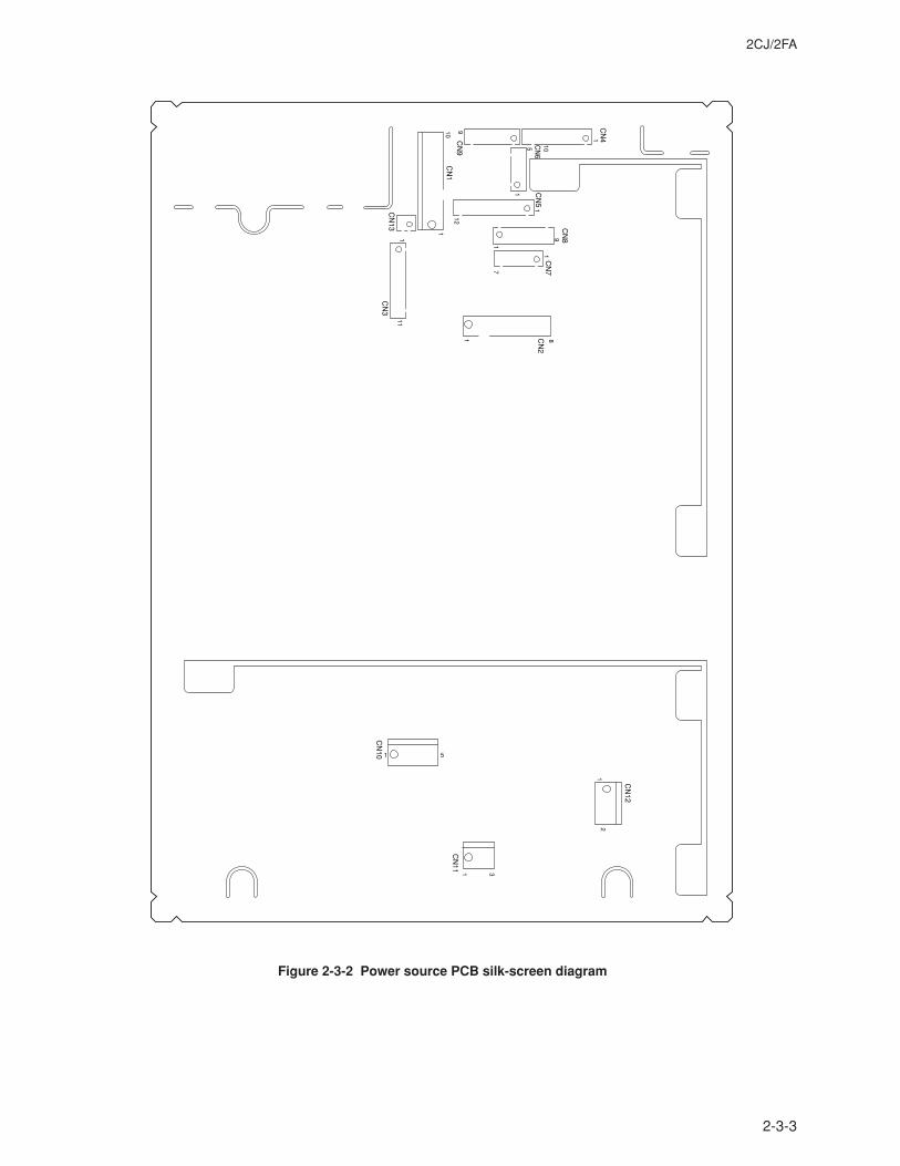
2CJ/2FA
2-3-3
CN
4
CN
5
CN
9
CN
13C
N3
CN
8
CN
7C
N2
CN
6105
1
1
1
111
910
9
1
1
CN
12
CN
11
1
1 3
CN
10 1 5
2
1
1
7
8
12C
N1
Figure 2-3-2 Power source PCB silk-screen diagram
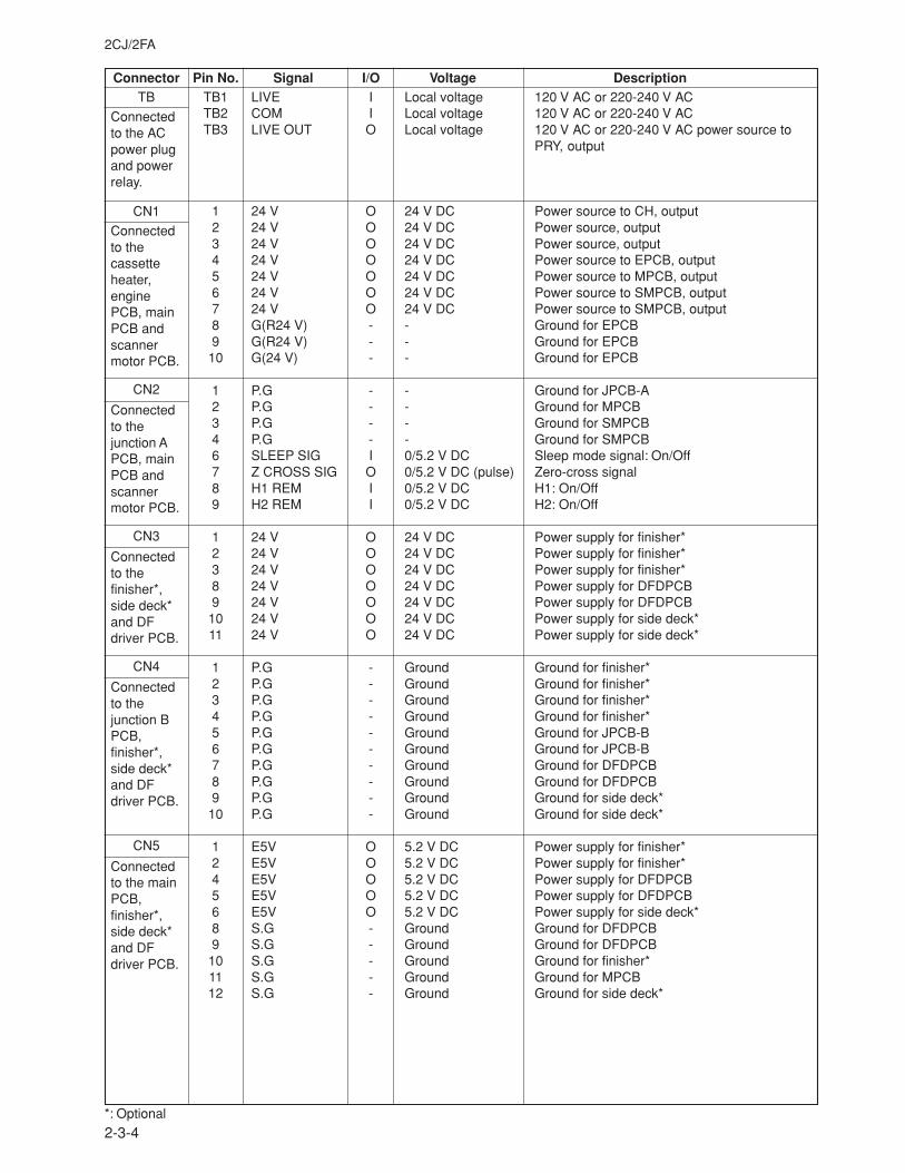
2CJ/2FA
2-3-4
Connector Pin No. Signal I/O Voltage DescriptionTB
Connectedto the ACpower plugand powerrelay.
CN1
Connectedto thecassetteheater,enginePCB, mainPCB andscannermotor PCB.
CN2
Connectedto thejunction APCB, mainPCB andscannermotor PCB.
CN3
Connectedto thefinisher*,side deck*and DFdriver PCB.
CN4
Connectedto thejunction BPCB,finisher*,side deck*and DFdriver PCB.
CN5
Connectedto the mainPCB,finisher*,side deck*and DFdriver PCB.
TB1 LIVE I Local voltage 120 V AC or 220-240 V ACTB2 COM I Local voltage 120 V AC or 220-240 V ACTB3 LIVE OUT O Local voltage 120 V AC or 220-240 V AC power source to
PRY, output
1 24 V O 24 V DC Power source to CH, output2 24 V O 24 V DC Power source, output3 24 V O 24 V DC Power source, output4 24 V O 24 V DC Power source to EPCB, output5 24 V O 24 V DC Power source to MPCB, output6 24 V O 24 V DC Power source to SMPCB, output7 24 V O 24 V DC Power source to SMPCB, output8 G(R24 V) - - Ground for EPCB9 G(R24 V) - - Ground for EPCB
10 G(24 V) - - Ground for EPCB
1 P.G - - Ground for JPCB-A2 P.G - - Ground for MPCB3 P.G - - Ground for SMPCB4 P.G - - Ground for SMPCB6 SLEEP SIG I 0/5.2 V DC Sleep mode signal: On/Off7 Z CROSS SIG O 0/5.2 V DC (pulse) Zero-cross signal8 H1 REM I 0/5.2 V DC H1: On/Off9 H2 REM I 0/5.2 V DC H2: On/Off
1 24 V O 24 V DC Power supply for finisher*2 24 V O 24 V DC Power supply for finisher*3 24 V O 24 V DC Power supply for finisher*8 24 V O 24 V DC Power supply for DFDPCB9 24 V O 24 V DC Power supply for DFDPCB
10 24 V O 24 V DC Power supply for side deck*11 24 V O 24 V DC Power supply for side deck*
1 P.G - Ground Ground for finisher*2 P.G - Ground Ground for finisher*3 P.G - Ground Ground for finisher*4 P.G - Ground Ground for finisher*5 P.G - Ground Ground for JPCB-B6 P.G - Ground Ground for JPCB-B7 P.G - Ground Ground for DFDPCB8 P.G - Ground Ground for DFDPCB9 P.G - Ground Ground for side deck*
10 P.G - Ground Ground for side deck*
1 E5V O 5.2 V DC Power supply for finisher*2 E5V O 5.2 V DC Power supply for finisher*4 E5V O 5.2 V DC Power supply for DFDPCB5 E5V O 5.2 V DC Power supply for DFDPCB6 E5V O 5.2 V DC Power supply for side deck*8 S.G - Ground Ground for DFDPCB9 S.G - Ground Ground for DFDPCB
10 S.G - Ground Ground for finisher*11 S.G - Ground Ground for MPCB12 S.G - Ground Ground for side deck*
*: Optional
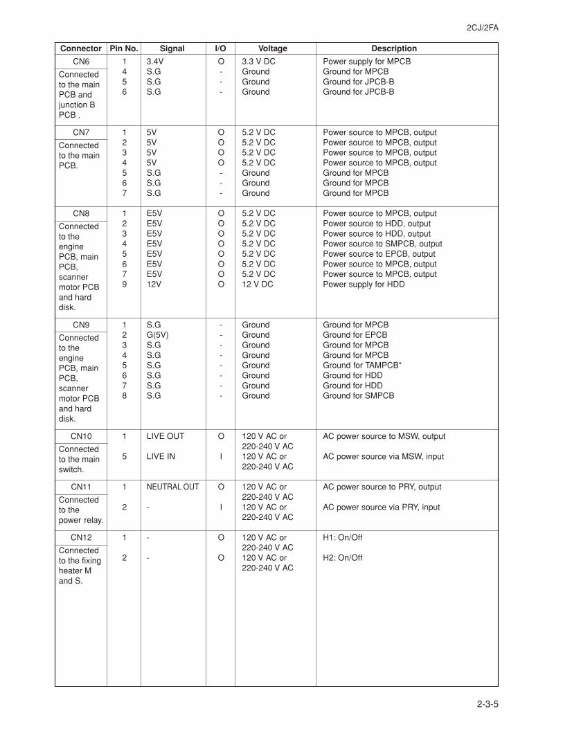
2CJ/2FA
2-3-5
Connector Pin No. Signal I/O Voltage Description
CN6
Connectedto the mainPCB andjunction BPCB .
CN7
Connectedto the mainPCB.
CN8
Connectedto theenginePCB, mainPCB,scannermotor PCBand harddisk.
CN9
Connectedto theenginePCB, mainPCB,scannermotor PCBand harddisk.
CN10
Connectedto the mainswitch.
CN11
Connectedto thepower relay.
CN12
Connectedto the fixingheater Mand S.
1 3.4V O 3.3 V DC Power supply for MPCB4 S.G - Ground Ground for MPCB5 S.G - Ground Ground for JPCB-B6 S.G - Ground Ground for JPCB-B
1 5V O 5.2 V DC Power source to MPCB, output2 5V O 5.2 V DC Power source to MPCB, output3 5V O 5.2 V DC Power source to MPCB, output4 5V O 5.2 V DC Power source to MPCB, output5 S.G - Ground Ground for MPCB6 S.G - Ground Ground for MPCB7 S.G - Ground Ground for MPCB
1 E5V O 5.2 V DC Power source to MPCB, output2 E5V O 5.2 V DC Power source to HDD, output3 E5V O 5.2 V DC Power source to HDD, output4 E5V O 5.2 V DC Power source to SMPCB, output5 E5V O 5.2 V DC Power source to EPCB, output6 E5V O 5.2 V DC Power source to MPCB, output7 E5V O 5.2 V DC Power source to MPCB, output9 12V O 12 V DC Power supply for HDD
1 S.G - Ground Ground for MPCB2 G(5V) - Ground Ground for EPCB3 S.G - Ground Ground for MPCB4 S.G - Ground Ground for MPCB5 S.G - Ground Ground for TAMPCB*6 S.G - Ground Ground for HDD7 S.G - Ground Ground for HDD8 S.G - Ground Ground for SMPCB
1 LIVE OUT O 120 V AC or AC power source to MSW, output220-240 V AC
5 LIVE IN I 120 V AC or AC power source via MSW, input220-240 V AC
1 NEUTRAL OUT O 120 V AC or AC power source to PRY, output220-240 V AC
2 - I 120 V AC or AC power source via PRY, input220-240 V AC
1 - O 120 V AC or H1: On/Off220-240 V AC
2 - O 120 V AC or H2: On/Off220-240 V AC
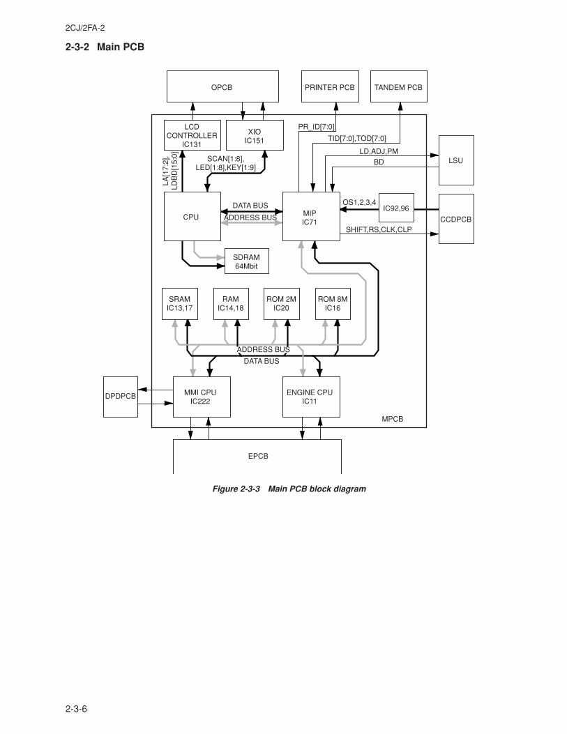
2CJ/2FA-2
2-3-6
2-3-2 Main PCB
ENGINE CPUIC11
MPCB
MIPIC71
CPU
LCDCONTROLLER
IC131
XIOIC151
PRINTER PCB TANDEM PCBOPCB
MMI CPUIC222
EPCB
DPDPCB
SRAMIC13,17
SDRAM64Mbit
RAMIC14,18
IC92,96DATA BUS
DATA BUS
OS1,2,3,4
SHIFT,RS,CLK,CLP
LD,ADJ,PM
TID[7:0],TOD[7:0]
SCAN[1:8],LED[1:8],KEY[1:9]
LA[1
7:2]
,LD
BD
[15:
0]
PR_ID[7:0]
BD
ADDRESS BUS
ROM 2MIC20
ROM 8MIC16
CCDPCB
LSU
ADDRESS BUS
Figure 2-3-3 Main PCB block diagram
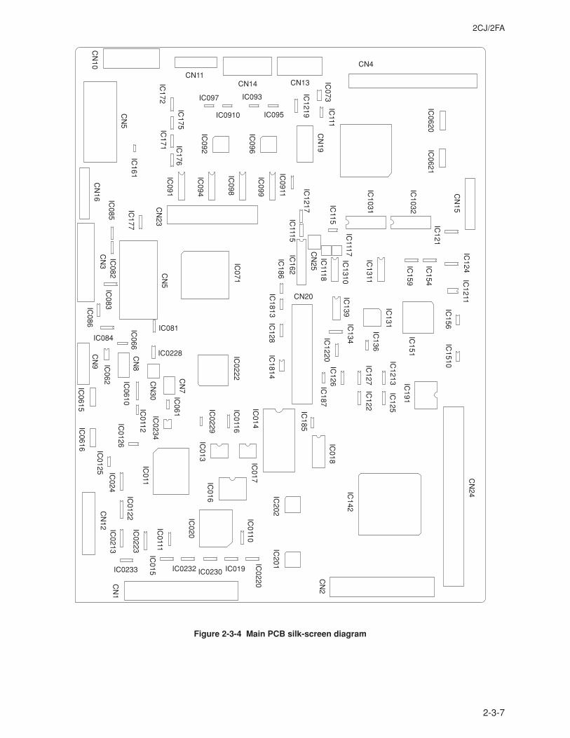
2CJ/2FA
2-3-7
IC136
IC191
IC1510
IC156
IC1211
IC124
IC121
IC154
IC159
IC1311
IC151
IC1213
IC125
IC122
IC127
IC126
IC1220
IC187
IC018
IC185
IC142
IC201
IC202
IC0110
IC020
IC0111
IC0223
IC0213
IC0122
IC024
IC0125
IC0616
IC0126
IC011
IC0234
IC061
IC0228
IC081IC
071
IC0112
IC0610
IC062
IC0615
IC086
IC083
IC082
IC085
IC177
IC161
IC171 IC
176
IC092
IC096
IC091
IC094
IC098
IC099
IC0911
IC1219
IC073
IC111
IC172
IC175
IC0229
IC0116
IC017IC
016IC
013
IC0222
IC014
IC1814
IC128
IC1813
IC186
IC162
IC1310
IC115
IC1117
IC1118
IC139
IC131IC
134
IC1115
IC1217
IC0220
IC019IC0230IC0232
IC015
IC084
IC066
IC097
IC0910
IC093
IC095
IC0233
IC1032
IC1031
IC0621
IC0620
CN
24
CN
2
CN
1
CN
12
CN
7
CN20
CN
30
CN
8
CN
9C
N3
CN
16
CN
5
CN
5C
N23
CN
10
CN11CN14 CN13
CN
19C
N25
CN4
CN
15
Figure 2-3-4 Main PCB silk-screen diagram
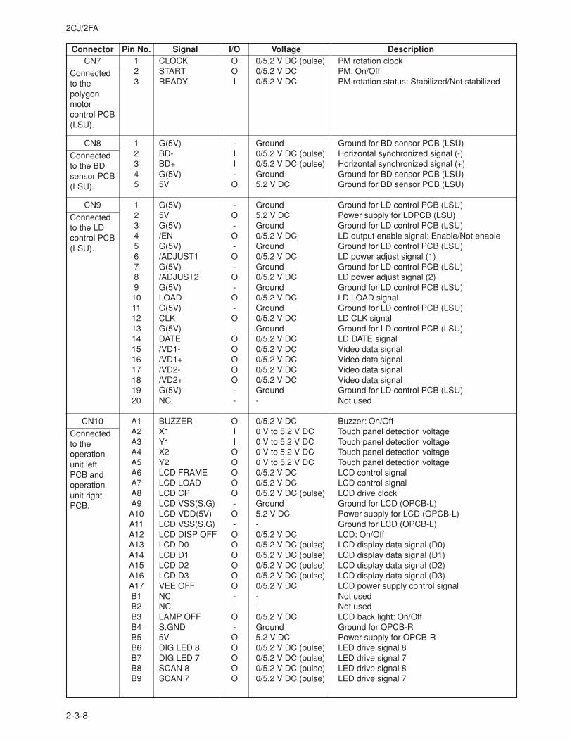
2CJ/2FA
2-3-8
Connector Pin No. Signal I/O Voltage DescriptionCN7
Connectedto thepolygonmotorcontrol PCB(LSU).
CN8
Connectedto the BDsensor PCB(LSU).
CN9
Connectedto the LDcontrol PCB(LSU).
CN10
Connectedto theoperationunit leftPCB andoperationunit rightPCB.
1 CLOCK O 0/5.2 V DC (pulse) PM rotation clock2 START O 0/5.2 V DC PM: On/Off3 READY I 0/5.2 V DC PM rotation status: Stabilized/Not stabilized
1 G(5V) - Ground Ground for BD sensor PCB (LSU)2 BD- I 0/5.2 V DC (pulse) Horizontal synchronized signal (-)3 BD+ I 0/5.2 V DC (pulse) Horizontal synchronized signal (+)4 G(5V) - Ground Ground for BD sensor PCB (LSU)5 5V O 5.2 V DC Ground for BD sensor PCB (LSU)
1 G(5V) - Ground Ground for LD control PCB (LSU)2 5V O 5.2 V DC Power supply for LDPCB (LSU)3 G(5V) - Ground Ground for LD control PCB (LSU)4 /EN O 0/5.2 V DC LD output enable signal: Enable/Not enable5 G(5V) - Ground Ground for LD control PCB (LSU)6 /ADJUST1 O 0/5.2 V DC LD power adjust signal (1)7 G(5V) - Ground Ground for LD control PCB (LSU)8 /ADJUST2 O 0/5.2 V DC LD power adjust signal (2)9 G(5V) - Ground Ground for LD control PCB (LSU)
10 LOAD O 0/5.2 V DC LD LOAD signal11 G(5V) - Ground Ground for LD control PCB (LSU)12 CLK O 0/5.2 V DC LD CLK signal13 G(5V) - Ground Ground for LD control PCB (LSU)14 DATE O 0/5.2 V DC LD DATE signal15 /VD1- O 0/5.2 V DC Video data signal16 /VD1+ O 0/5.2 V DC Video data signal17 /VD2- O 0/5.2 V DC Video data signal18 /VD2+ O 0/5.2 V DC Video data signal19 G(5V) - Ground Ground for LD control PCB (LSU)20 NC - - Not used
A1 BUZZER O 0/5.2 V DC Buzzer: On/OffA2 X1 I 0 V to 5.2 V DC Touch panel detection voltageA3 Y1 I 0 V to 5.2 V DC Touch panel detection voltageA4 X2 O 0 V to 5.2 V DC Touch panel detection voltageA5 Y2 O 0 V to 5.2 V DC Touch panel detection voltageA6 LCD FRAME O 0/5.2 V DC LCD control signalA7 LCD LOAD O 0/5.2 V DC LCD control signalA8 LCD CP O 0/5.2 V DC (pulse) LCD drive clockA9 LCD VSS(S.G) - Ground Ground for LCD (OPCB-L)
A10 LCD VDD(5V) O 5.2 V DC Power supply for LCD (OPCB-L)A11 LCD VSS(S.G) - - Ground for LCD (OPCB-L)A12 LCD DISP OFF O 0/5.2 V DC LCD: On/OffA13 LCD D0 O 0/5.2 V DC (pulse) LCD display data signal (D0)A14 LCD D1 O 0/5.2 V DC (pulse) LCD display data signal (D1)A15 LCD D2 O 0/5.2 V DC (pulse) LCD display data signal (D2)A16 LCD D3 O 0/5.2 V DC (pulse) LCD display data signal (D3)A17 VEE OFF O 0/5.2 V DC LCD power supply control signalB1 NC - - Not usedB2 NC - - Not usedB3 LAMP OFF O 0/5.2 V DC LCD back light: On/OffB4 S.GND - Ground Ground for OPCB-RB5 5V O 5.2 V DC Power supply for OPCB-RB6 DIG LED 8 O 0/5.2 V DC (pulse) LED drive signal 8B7 DIG LED 7 O 0/5.2 V DC (pulse) LED drive signal 7B8 SCAN 8 O 0/5.2 V DC (pulse) LED drive signal 8B9 SCAN 7 O 0/5.2 V DC (pulse) LED drive signal 7
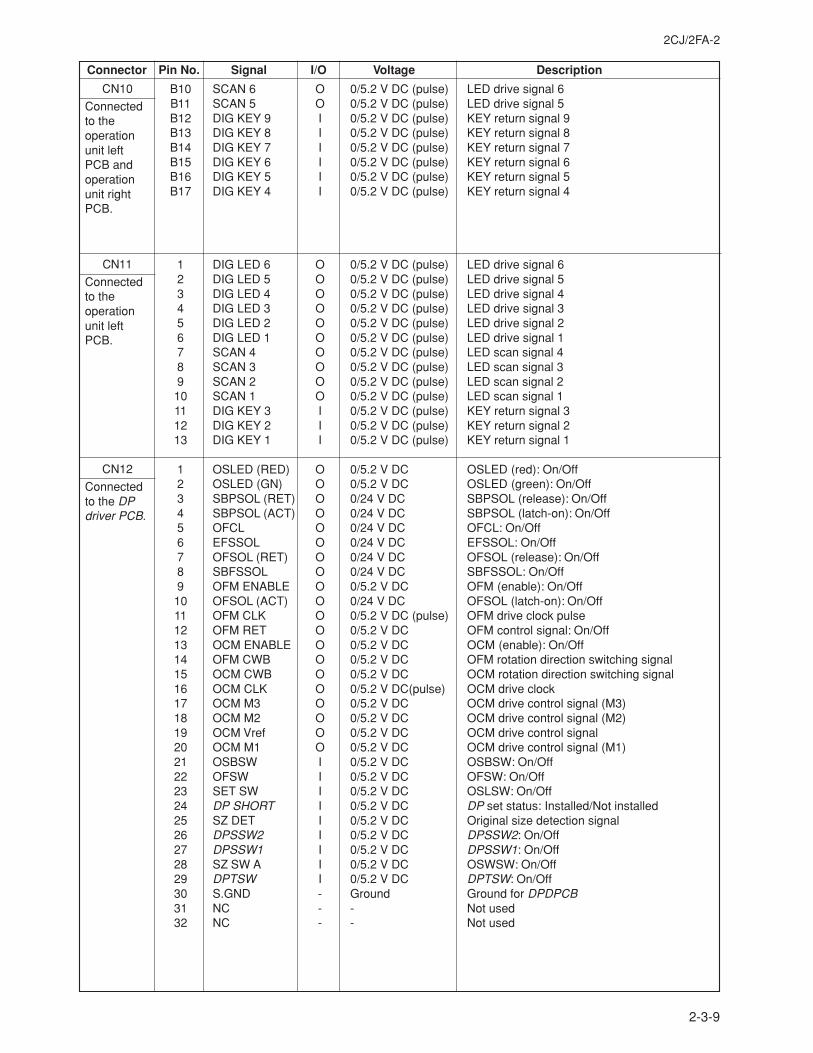
2CJ/2FA-2
2-3-9
Connector Pin No. Signal I/O Voltage Description
B10 SCAN 6 O 0/5.2 V DC (pulse) LED drive signal 6B11 SCAN 5 O 0/5.2 V DC (pulse) LED drive signal 5B12 DIG KEY 9 I 0/5.2 V DC (pulse) KEY return signal 9B13 DIG KEY 8 I 0/5.2 V DC (pulse) KEY return signal 8B14 DIG KEY 7 I 0/5.2 V DC (pulse) KEY return signal 7B15 DIG KEY 6 I 0/5.2 V DC (pulse) KEY return signal 6B16 DIG KEY 5 I 0/5.2 V DC (pulse) KEY return signal 5B17 DIG KEY 4 I 0/5.2 V DC (pulse) KEY return signal 4
1 DIG LED 6 O 0/5.2 V DC (pulse) LED drive signal 62 DIG LED 5 O 0/5.2 V DC (pulse) LED drive signal 53 DIG LED 4 O 0/5.2 V DC (pulse) LED drive signal 44 DIG LED 3 O 0/5.2 V DC (pulse) LED drive signal 35 DIG LED 2 O 0/5.2 V DC (pulse) LED drive signal 26 DIG LED 1 O 0/5.2 V DC (pulse) LED drive signal 17 SCAN 4 O 0/5.2 V DC (pulse) LED scan signal 48 SCAN 3 O 0/5.2 V DC (pulse) LED scan signal 39 SCAN 2 O 0/5.2 V DC (pulse) LED scan signal 210 SCAN 1 O 0/5.2 V DC (pulse) LED scan signal 111 DIG KEY 3 I 0/5.2 V DC (pulse) KEY return signal 312 DIG KEY 2 I 0/5.2 V DC (pulse) KEY return signal 213 DIG KEY 1 I 0/5.2 V DC (pulse) KEY return signal 1
1 OSLED (RED) O 0/5.2 V DC OSLED (red): On/Off2 OSLED (GN) O 0/5.2 V DC OSLED (green): On/Off3 SBPSOL (RET) O 0/24 V DC SBPSOL (release): On/Off4 SBPSOL (ACT) O 0/24 V DC SBPSOL (latch-on): On/Off5 OFCL O 0/24 V DC OFCL: On/Off6 EFSSOL O 0/24 V DC EFSSOL: On/Off7 OFSOL (RET) O 0/24 V DC OFSOL (release): On/Off8 SBFSSOL O 0/24 V DC SBFSSOL: On/Off9 OFM ENABLE O 0/5.2 V DC OFM (enable): On/Off10 OFSOL (ACT) O 0/24 V DC OFSOL (latch-on): On/Off11 OFM CLK O 0/5.2 V DC (pulse) OFM drive clock pulse12 OFM RET O 0/5.2 V DC OFM control signal: On/Off13 OCM ENABLE O 0/5.2 V DC OCM (enable): On/Off14 OFM CWB O 0/5.2 V DC OFM rotation direction switching signal15 OCM CWB O 0/5.2 V DC OCM rotation direction switching signal16 OCM CLK O 0/5.2 V DC(pulse) OCM drive clock17 OCM M3 O 0/5.2 V DC OCM drive control signal (M3)18 OCM M2 O 0/5.2 V DC OCM drive control signal (M2)19 OCM Vref O 0/5.2 V DC OCM drive control signal20 OCM M1 O 0/5.2 V DC OCM drive control signal (M1)21 OSBSW I 0/5.2 V DC OSBSW: On/Off22 OFSW I 0/5.2 V DC OFSW: On/Off23 SET SW I 0/5.2 V DC OSLSW: On/Off24 DP SHORT I 0/5.2 V DC DP set status: Installed/Not installed25 SZ DET I 0/5.2 V DC Original size detection signal26 DPSSW2 I 0/5.2 V DC DPSSW2: On/Off27 DPSSW1 I 0/5.2 V DC DPSSW1: On/Off28 SZ SW A I 0/5.2 V DC OSWSW: On/Off29 DPTSW I 0/5.2 V DC DPTSW: On/Off30 S.GND - Ground Ground for DPDPCB31 NC - - Not used32 NC - - Not used
CN10
Connectedto theoperationunit leftPCB andoperationunit rightPCB.
CN11
Connectedto theoperationunit leftPCB.
CN12
Connectedto the DPdriver PCB.
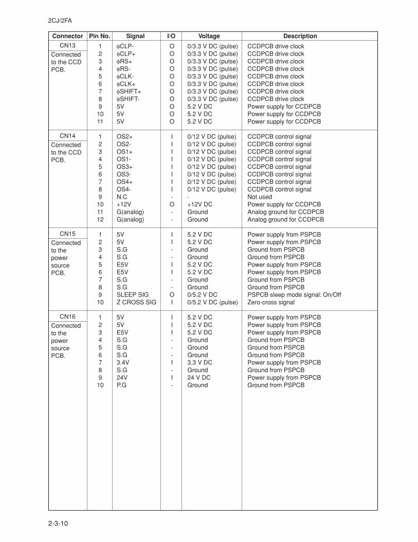
2CJ/2FA
2-3-10
Connector Pin No. Signal I/O Voltage Description
CN13
Connectedto the CCDPCB.
CN14
Connectedto the CCDPCB.
CN15
Connectedto thepowersourcePCB.
CN16
Connectedto thepowersourcePCB.
1 φCLP- O 0/3.3 V DC (pulse) CCDPCB drive clock2 φCLP+ O 0/3.3 V DC (pulse) CCDPCB drive clock3 φRS+ O 0/3.3 V DC (pulse) CCDPCB drive clock4 φRS- O 0/3.3 V DC (pulse) CCDPCB drive clock5 φCLK- O 0/3.3 V DC (pulse) CCDPCB drive clock6 φCLK+ O 0/3.3 V DC (pulse) CCDPCB drive clock7 φSHIFT+ O 0/3.3 V DC (pulse) CCDPCB drive clock8 φSHIFT- O 0/3.3 V DC (pulse) CCDPCB drive clock9 5V O 5.2 V DC Power supply for CCDPCB
10 5V O 5.2 V DC Power supply for CCDPCB11 5V O 5.2 V DC Power supply for CCDPCB
1 OS2+ I 0/12 V DC (pulse) CCDPCB control signal2 OS2- I 0/12 V DC (pulse) CCDPCB control signal3 OS1+ I 0/12 V DC (pulse) CCDPCB control signal4 OS1- I 0/12 V DC (pulse) CCDPCB control signal5 OS3+ I 0/12 V DC (pulse) CCDPCB control signal6 OS3- I 0/12 V DC (pulse) CCDPCB control signal7 OS4+ I 0/12 V DC (pulse) CCDPCB control signal8 OS4- I 0/12 V DC (pulse) CCDPCB control signal9 N.C - - Not used
10 +12V O +12V DC Power supply for CCDPCB11 G(analog) - Ground Analog ground for CCDPCB12 G(analog) - Ground Analog ground for CCDPCB
1 5V I 5.2 V DC Power supply from PSPCB2 5V I 5.2 V DC Power supply from PSPCB3 S.G - Ground Ground from PSPCB4 S.G - Ground Ground from PSPCB5 E5V I 5.2 V DC Power supply from PSPCB6 E5V I 5.2 V DC Power supply from PSPCB7 S.G - Ground Ground from PSPCB8 S.G - Ground Ground from PSPCB9 SLEEP SIG O 0/5.2 V DC PSPCB sleep mode signal: On/Off
10 Z CROSS SIG I 0/5.2 V DC (pulse) Zero-cross signal
1 5V I 5.2 V DC Power supply from PSPCB2 5V I 5.2 V DC Power supply from PSPCB3 E5V I 5.2 V DC Power supply from PSPCB4 S.G - Ground Ground from PSPCB5 S.G - Ground Ground from PSPCB6 S.G - Ground Ground from PSPCB7 3.4V I 3.3 V DC Power supply from PSPCB8 S.G - Ground Ground from PSPCB9 24V I 24 V DC Power supply from PSPCB
10 P.G - Ground Ground from PSPCB
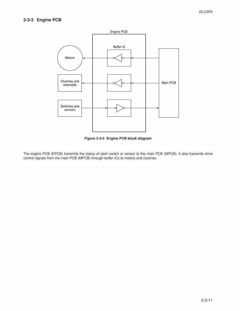
2CJ/2FA
2-3-11
2-3-3 Engine PCB
Engine PCB
Clutches andsolenoids
Switches andsensors
Motors
Buffer IC
Main PCB
Figure 2-3-5 Engine PCB block diagram
The engine PCB (EPCB) transmits the status of each switch or sensor to the main PCB (MPCB). It also transmits drivecontrol signals from the main PCB (MPCB) through buffer ICs to motors and clutches.
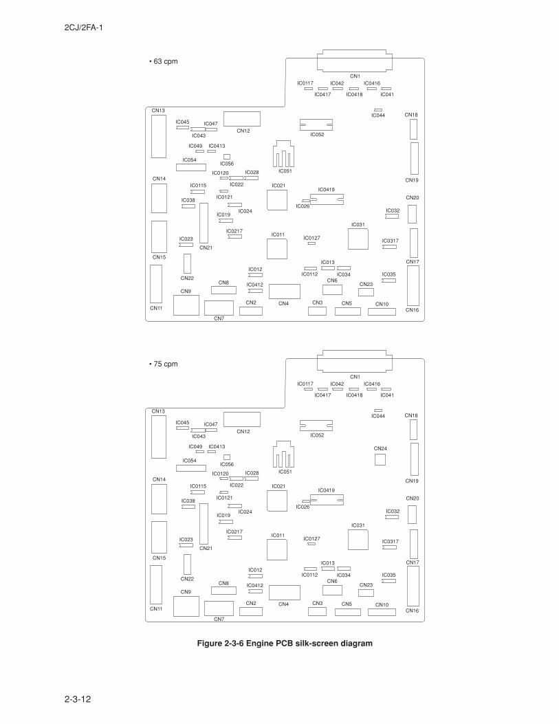
2CJ/2FA-1
2-3-12
Figure 2-3-6 Engine PCB silk-screen diagram
CN1
IC044
IC041
IC0416
IC0418
IC042
IC0417
IC0117
IC052
IC051
IC026
IC0419
IC032
IC0317
IC035IC034
IC013
IC0112
IC0127
IC031
IC011
IC021
IC019IC024
IC0217
IC0121
IC022
IC0120 IC028
IC0115
IC038
IC023
CN21
CN13
CN12
IC012
IC0412
IC045
IC043
IC047
IC049 IC0413
IC056
CN14
CN15
CN11
CN9
CN22CN8
CN2
CN7
CN4 CN3 CN5 CN10
CN23CN6
CN16
CN17
CN20
CN19
CN18
IC054
CN1
IC044
IC041
IC0416
IC0418
IC042
IC0417
IC0117
IC052
IC051
IC026
IC0419
IC032
IC0317
IC035IC034
IC013
IC0112
IC0127
IC031
IC011
IC021
IC019IC024
IC0217
IC0121
IC022
IC0120 IC028
IC0115
IC038
IC023
CN21
CN13
• 75 cpm
• 63 cpm
CN12
IC012
IC0412
IC045
IC043
IC047
IC049 IC0413
IC056
CN14
CN15
CN11
CN9
CN22CN8
CN2
CN7
CN4 CN3 CN5 CN10
CN23CN6
CN16
CN17
CN20
CN24
CN19
CN18
IC054
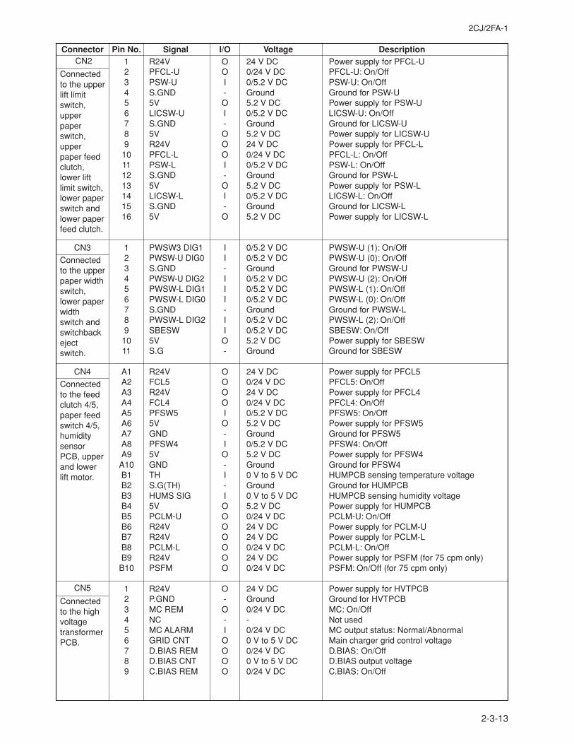
2CJ/2FA-1
2-3-13
Connector Pin No. Signal I/O Voltage Description CN2
Connectedto the upperlift limitswitch,upperpaperswitch,upperpaper feedclutch,lower liftlimit switch,lower paperswitch andlower paperfeed clutch.
CN3
Connectedto the upperpaper widthswitch,lower paperwidthswitch andswitchbackejectswitch.
CN4
Connectedto the feedclutch 4/5,paper feedswitch 4/5,humiditysensorPCB, upperand lowerlift motor.
CN5
Connectedto the highvoltagetransformerPCB.
1 R24V O 24 V DC Power supply for PFCL-U2 PFCL-U O 0/24 V DC PFCL-U: On/Off3 PSW-U I 0/5.2 V DC PSW-U: On/Off4 S.GND - Ground Ground for PSW-U5 5V O 5.2 V DC Power supply for PSW-U6 LICSW-U I 0/5.2 V DC LICSW-U: On/Off7 S.GND - Ground Ground for LICSW-U8 5V O 5.2 V DC Power supply for LICSW-U9 R24V O 24 V DC Power supply for PFCL-L
10 PFCL-L O 0/24 V DC PFCL-L: On/Off11 PSW-L I 0/5.2 V DC PSW-L: On/Off12 S.GND - Ground Ground for PSW-L13 5V O 5.2 V DC Power supply for PSW-L14 LICSW-L I 0/5.2 V DC LICSW-L: On/Off15 S.GND - Ground Ground for LICSW-L16 5V O 5.2 V DC Power supply for LICSW-L
1 PWSW3 DIG1 I 0/5.2 V DC PWSW-U (1): On/Off2 PWSW-U DIG0 I 0/5.2 V DC PWSW-U (0): On/Off3 S.GND - Ground Ground for PWSW-U4 PWSW-U DIG2 I 0/5.2 V DC PWSW-U (2): On/Off5 PWSW-L DIG1 I 0/5.2 V DC PWSW-L (1): On/Off6 PWSW-L DIG0 I 0/5.2 V DC PWSW-L (0): On/Off7 S.GND - Ground Ground for PWSW-L8 PWSW-L DIG2 I 0/5.2 V DC PWSW-L (2): On/Off9 SBESW I 0/5.2 V DC SBESW: On/Off
10 5V O 5.2 V DC Power supply for SBESW11 S.G - Ground Ground for SBESW
A1 R24V O 24 V DC Power supply for PFCL5A2 FCL5 O 0/24 V DC PFCL5: On/OffA3 R24V O 24 V DC Power supply for PFCL4A4 FCL4 O 0/24 V DC PFCL4: On/OffA5 PFSW5 I 0/5.2 V DC PFSW5: On/OffA6 5V O 5.2 V DC Power supply for PFSW5A7 GND - Ground Ground for PFSW5A8 PFSW4 I 0/5.2 V DC PFSW4: On/OffA9 5V O 5.2 V DC Power supply for PFSW4
A10 GND - Ground Ground for PFSW4B1 TH I 0 V to 5 V DC HUMPCB sensing temperature voltageB2 S.G(TH) - Ground Ground for HUMPCBB3 HUMS SIG I 0 V to 5 V DC HUMPCB sensing humidity voltageB4 5V O 5.2 V DC Power supply for HUMPCBB5 PCLM-U O 0/24 V DC PCLM-U: On/OffB6 R24V O 24 V DC Power supply for PCLM-UB7 R24V O 24 V DC Power supply for PCLM-LB8 PCLM-L O 0/24 V DC PCLM-L: On/OffB9 R24V O 24 V DC Power supply for PSFM (for 75 cpm only)
B10 PSFM O 0/24 V DC PSFM: On/Off (for 75 cpm only)
1 R24V O 24 V DC Power supply for HVTPCB2 P.GND - Ground Ground for HVTPCB3 MC REM O 0/24 V DC MC: On/Off4 NC - - Not used5 MC ALARM I 0/24 V DC MC output status: Normal/Abnormal6 GRID CNT O 0 V to 5 V DC Main charger grid control voltage7 D.BIAS REM O 0/24 V DC D.BIAS: On/Off8 D.BIAS CNT O 0 V to 5 V DC D.BIAS output voltage9 C.BIAS REM O 0/24 V DC C.BIAS: On/Off
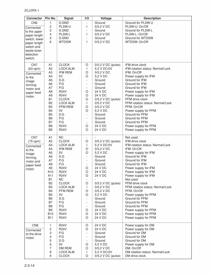
2CJ/2FA-1
2-3-14
Connector Pin No. Signal I/O Voltage DescriptionCN6
Connectedto the upperpaper lengthswitch, lowerpaper lengthswitch andwaste tonerdetectionswitch.
CN7(63 cpm)
Connectedto theimageformingmotor andpaper feedmotor.
CN7(75 cpm)
Connectedto theimageformingmotor andpaper feedmotor.
CN8
Connectedto the drivemotor.
1 S.GND - Ground Ground for PLSW-U2 PLSW-U I 0/5.2 V DC PLSW-U: On/Off3 S.GND - Ground Ground for PLSW-L4 PLSW-L I 0/5.2 V DC PLSW-L: On/Off5 S.GND - Ground Ground for WTDSW6 WTDSW I 0/5.2 V DC WTDSW: On/Off
A1 CLOCK O 0/5.2 V DC (pulse) IFM drive clockA2 LOCK ALM I 5.2 V DC/0V IFM rotation status: Normal/LockA3 IFM REM O 0/5.2 V DC IFM: On/OffA4 5V O 5.2 V DC Power supply for IFMA5 S.G - Ground Ground for IFMA6 P.G - Ground Ground for IFMA7 P.G - Ground Ground for IFMA8 R24V O 24 V DC Power supply for IFMA9 R24V O 24 V DC Power supply for IFMB1 CLOCK O 0/5.2 V DC (pulse) PFM drive clockB2 LOCK ALM I 0/5.2 V DC PFM rotation status: Normal/LockB3 PFM REM O 0/5.2 V DC PFM: On/OffB4 5V O 5.2 V DC Power supply for PFMB5 S.G - Ground Ground for PFMB6 P.G - Ground Ground for PFMB7 P.G - Ground Ground for PFMB8 R24V O 24 V DC Power supply for PFMB9 R24V O 24 V DC Power supply for PFM
A1 NC - - Not usedA2 CLOCK O 0/5.2 V DC (pulse) IFM drive clockA3 LOCK ALM I 5.2 V DC/0V IFM rotation status: Normal/LockA4 IFM REM O 0/5.2 V DC IFM: On/OffA5 5V O 5.2 V DC Power supply for IFMA6 S.G - Ground Ground for IFMA7 P.G - Ground Ground for IFMA8 P.G - Ground Ground for IFMA9 R24V O 24 V DC Power supply for IFM
A10 R24V O 24 V DC Power supply for IFMA11 R24V O 24 V DC Power supply for IFMB1 NC - - Not usedB2 CLOCK O 0/5.2 V DC (pulse) PFM drive clockB3 LOCK ALM I 0/5.2 V DC PFM rotation status: Normal/LockB4 PFM REM O 0/5.2 V DC PFM: On/OffB5 5V O 5.2 V DC Power supply for PFMB6 S.G - Ground Ground for PFMB7 P.G - Ground Ground for PFMB8 P.G - Ground Ground for PFMB9 R24V O 24 V DC Power supply for PFM
B10 R24V O 24 V DC Power supply for PFMB11 R24V O 24 V DC Power supply for PFM
1 R24V O 24 V DC Power supply for DM2 R24V O 24 V DC Power supply for DM3 P.G - Ground Ground for DM4 P.G - Ground Ground for DM5 S.G - Ground Ground for DM6 5V O 5.2 V DC Power supply for DM7 DM REM O 0/5.2 V DC DM: On/Off8 LOCK ALM I 5.2 V DC/0V DM rotation status: Normal/Lock9 CLOCK O 0/5.2 V DC (pulse) DM drive clock
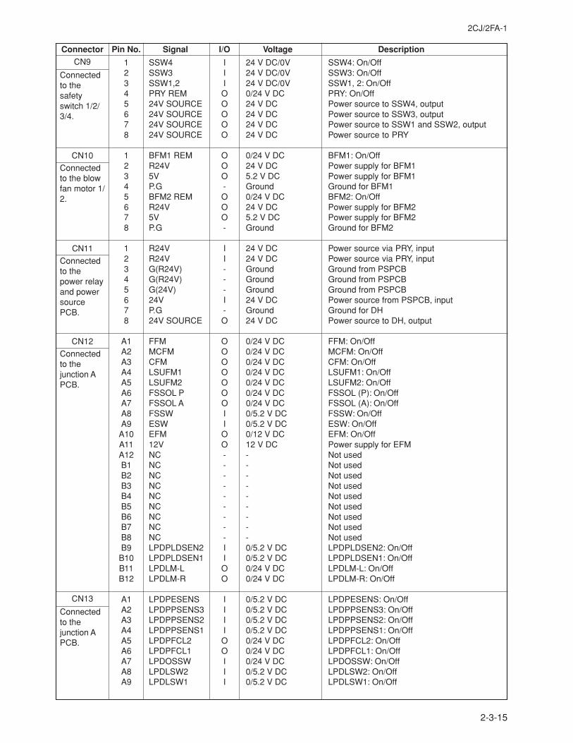
2CJ/2FA-1
2-3-15
Connector Pin No. Signal I/O Voltage DescriptionCN9
Connectedto thesafetyswitch 1/2/3/4.
CN10
Connectedto the blowfan motor 1/2.
CN11
Connectedto thepower relayand powersourcePCB.
CN12
Connectedto thejunction APCB.
CN13
Connectedto thejunction APCB.
1 SSW4 I 24 V DC/0V SSW4: On/Off2 SSW3 I 24 V DC/0V SSW3: On/Off3 SSW1,2 I 24 V DC/0V SSW1, 2: On/Off4 PRY REM O 0/24 V DC PRY: On/Off5 24V SOURCE O 24 V DC Power source to SSW4, output6 24V SOURCE O 24 V DC Power source to SSW3, output7 24V SOURCE O 24 V DC Power source to SSW1 and SSW2, output8 24V SOURCE O 24 V DC Power source to PRY
1 BFM1 REM O 0/24 V DC BFM1: On/Off2 R24V O 24 V DC Power supply for BFM13 5V O 5.2 V DC Power supply for BFM14 P.G - Ground Ground for BFM15 BFM2 REM O 0/24 V DC BFM2: On/Off6 R24V O 24 V DC Power supply for BFM27 5V O 5.2 V DC Power supply for BFM28 P.G - Ground Ground for BFM2
1 R24V I 24 V DC Power source via PRY, input2 R24V I 24 V DC Power source via PRY, input3 G(R24V) - Ground Ground from PSPCB4 G(R24V) - Ground Ground from PSPCB5 G(24V) - Ground Ground from PSPCB6 24V I 24 V DC Power source from PSPCB, input7 P.G - Ground Ground for DH8 24V SOURCE O 24 V DC Power source to DH, output
A1 FFM O 0/24 V DC FFM: On/OffA2 MCFM O 0/24 V DC MCFM: On/OffA3 CFM O 0/24 V DC CFM: On/OffA4 LSUFM1 O 0/24 V DC LSUFM1: On/OffA5 LSUFM2 O 0/24 V DC LSUFM2: On/OffA6 FSSOL P O 0/24 V DC FSSOL (P): On/OffA7 FSSOL A O 0/24 V DC FSSOL (A): On/OffA8 FSSW I 0/5.2 V DC FSSW: On/OffA9 ESW I 0/5.2 V DC ESW: On/Off
A10 EFM O 0/12 V DC EFM: On/OffA11 12V O 12 V DC Power supply for EFMA12 NC - - Not usedB1 NC - - Not usedB2 NC - - Not usedB3 NC - - Not usedB4 NC - - Not usedB5 NC - - Not usedB6 NC - - Not usedB7 NC - - Not usedB8 NC - - Not usedB9 LPDPLDSEN2 I 0/5.2 V DC LPDPLDSEN2: On/Off
B10 LPDPLDSEN1 I 0/5.2 V DC LPDPLDSEN1: On/OffB11 LPDLM-L O 0/24 V DC LPDLM-L: On/OffB12 LPDLM-R O 0/24 V DC LPDLM-R: On/Off
A1 LPDPESENS I 0/5.2 V DC LPDPESENS: On/OffA2 LPDPPSENS3 I 0/5.2 V DC LPDPPSENS3: On/OffA3 LPDPPSENS2 I 0/5.2 V DC LPDPPSENS2: On/OffA4 LPDPPSENS1 I 0/5.2 V DC LPDPPSENS1: On/OffA5 LPDPFCL2 O 0/24 V DC LPDPFCL2: On/OffA6 LPDPFCL1 O 0/24 V DC LPDPFCL1: On/OffA7 LPDOSSW I 0/24 V DC LPDOSSW: On/OffA8 LPDLSW2 I 0/5.2 V DC LPDLSW2: On/OffA9 LPDLSW1 I 0/5.2 V DC LPDLSW1: On/Off
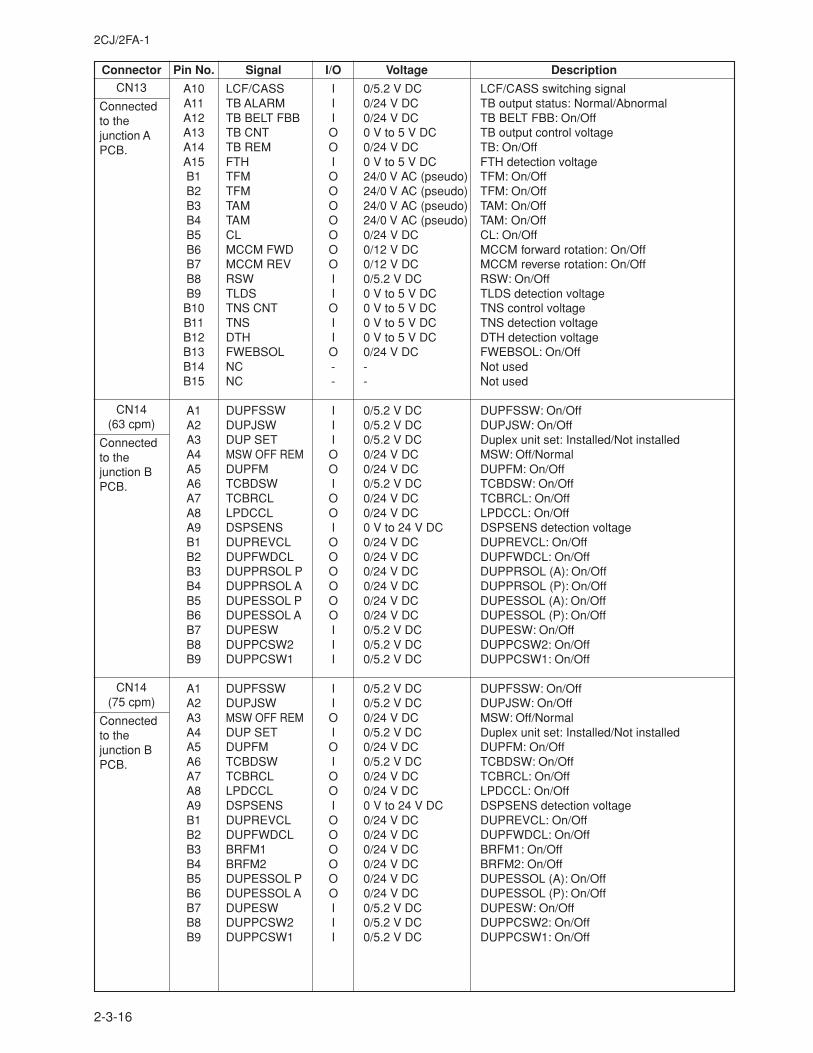
2CJ/2FA-1
2-3-16
Connector Pin No. Signal I/O Voltage DescriptionCN13
Connectedto thejunction APCB.
CN14(63 cpm)
Connectedto thejunction BPCB.
CN14(75 cpm)
Connectedto thejunction BPCB.
A10 LCF/CASS I 0/5.2 V DC LCF/CASS switching signalA11 TB ALARM I 0/24 V DC TB output status: Normal/AbnormalA12 TB BELT FBB I 0/24 V DC TB BELT FBB: On/OffA13 TB CNT O 0 V to 5 V DC TB output control voltageA14 TB REM O 0/24 V DC TB: On/OffA15 FTH I 0 V to 5 V DC FTH detection voltageB1 TFM O 24/0 V AC (pseudo) TFM: On/OffB2 TFM O 24/0 V AC (pseudo) TFM: On/OffB3 TAM O 24/0 V AC (pseudo) TAM: On/OffB4 TAM O 24/0 V AC (pseudo) TAM: On/OffB5 CL O 0/24 V DC CL: On/OffB6 MCCM FWD O 0/12 V DC MCCM forward rotation: On/OffB7 MCCM REV O 0/12 V DC MCCM reverse rotation: On/OffB8 RSW I 0/5.2 V DC RSW: On/OffB9 TLDS I 0 V to 5 V DC TLDS detection voltageB10 TNS CNT O 0 V to 5 V DC TNS control voltageB11 TNS I 0 V to 5 V DC TNS detection voltageB12 DTH I 0 V to 5 V DC DTH detection voltageB13 FWEBSOL O 0/24 V DC FWEBSOL: On/OffB14 NC - - Not usedB15 NC - - Not used
A1 DUPFSSW I 0/5.2 V DC DUPFSSW: On/OffA2 DUPJSW I 0/5.2 V DC DUPJSW: On/OffA3 DUP SET I 0/5.2 V DC Duplex unit set: Installed/Not installedA4 MSW OFF REM O 0/24 V DC MSW: Off/NormalA5 DUPFM O 0/24 V DC DUPFM: On/OffA6 TCBDSW I 0/5.2 V DC TCBDSW: On/OffA7 TCBRCL O 0/24 V DC TCBRCL: On/OffA8 LPDCCL O 0/24 V DC LPDCCL: On/OffA9 DSPSENS I 0 V to 24 V DC DSPSENS detection voltageB1 DUPREVCL O 0/24 V DC DUPREVCL: On/OffB2 DUPFWDCL O 0/24 V DC DUPFWDCL: On/OffB3 DUPPRSOL P O 0/24 V DC DUPPRSOL (A): On/OffB4 DUPPRSOL A O 0/24 V DC DUPPRSOL (P): On/OffB5 DUPESSOL P O 0/24 V DC DUPESSOL (A): On/OffB6 DUPESSOL A O 0/24 V DC DUPESSOL (P): On/OffB7 DUPESW I 0/5.2 V DC DUPESW: On/OffB8 DUPPCSW2 I 0/5.2 V DC DUPPCSW2: On/OffB9 DUPPCSW1 I 0/5.2 V DC DUPPCSW1: On/Off
A1 DUPFSSW I 0/5.2 V DC DUPFSSW: On/OffA2 DUPJSW I 0/5.2 V DC DUPJSW: On/OffA3 MSW OFF REM O 0/24 V DC MSW: Off/NormalA4 DUP SET I 0/5.2 V DC Duplex unit set: Installed/Not installedA5 DUPFM O 0/24 V DC DUPFM: On/OffA6 TCBDSW I 0/5.2 V DC TCBDSW: On/OffA7 TCBRCL O 0/24 V DC TCBRCL: On/OffA8 LPDCCL O 0/24 V DC LPDCCL: On/OffA9 DSPSENS I 0 V to 24 V DC DSPSENS detection voltageB1 DUPREVCL O 0/24 V DC DUPREVCL: On/OffB2 DUPFWDCL O 0/24 V DC DUPFWDCL: On/OffB3 BRFM1 O 0/24 V DC BRFM1: On/OffB4 BRFM2 O 0/24 V DC BRFM2: On/OffB5 DUPESSOL P O 0/24 V DC DUPESSOL (A): On/OffB6 DUPESSOL A O 0/24 V DC DUPESSOL (P): On/OffB7 DUPESW I 0/5.2 V DC DUPESW: On/OffB8 DUPPCSW2 I 0/5.2 V DC DUPPCSW2: On/OffB9 DUPPCSW1 I 0/5.2 V DC DUPPCSW1: On/Off
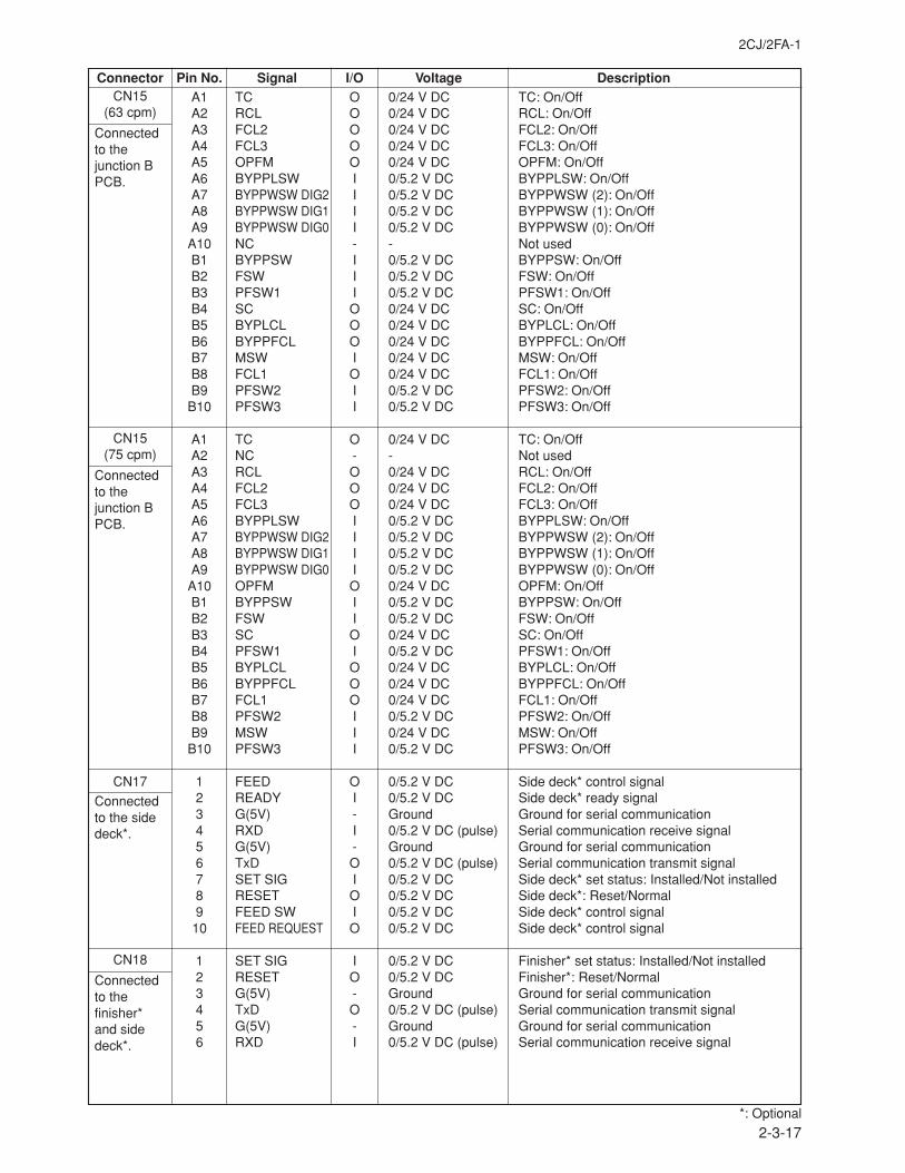
2CJ/2FA-1
2-3-17
Connector Pin No. Signal I/O Voltage DescriptionCN15
(63 cpm)
Connectedto thejunction BPCB.
CN15(75 cpm)
Connectedto thejunction BPCB.
CN17
Connectedto the sidedeck*.
CN18
Connectedto thefinisher*and sidedeck*.
A1 TC O 0/24 V DC TC: On/OffA2 RCL O 0/24 V DC RCL: On/OffA3 FCL2 O 0/24 V DC FCL2: On/OffA4 FCL3 O 0/24 V DC FCL3: On/OffA5 OPFM O 0/24 V DC OPFM: On/OffA6 BYPPLSW I 0/5.2 V DC BYPPLSW: On/OffA7 BYPPWSW DIG2 I 0/5.2 V DC BYPPWSW (2): On/OffA8 BYPPWSW DIG1 I 0/5.2 V DC BYPPWSW (1): On/OffA9 BYPPWSW DIG0 I 0/5.2 V DC BYPPWSW (0): On/Off
A10 NC - - Not usedB1 BYPPSW I 0/5.2 V DC BYPPSW: On/OffB2 FSW I 0/5.2 V DC FSW: On/OffB3 PFSW1 I 0/5.2 V DC PFSW1: On/OffB4 SC O 0/24 V DC SC: On/OffB5 BYPLCL O 0/24 V DC BYPLCL: On/OffB6 BYPPFCL O 0/24 V DC BYPPFCL: On/OffB7 MSW I 0/24 V DC MSW: On/OffB8 FCL1 O 0/24 V DC FCL1: On/OffB9 PFSW2 I 0/5.2 V DC PFSW2: On/Off
B10 PFSW3 I 0/5.2 V DC PFSW3: On/Off
A1 TC O 0/24 V DC TC: On/OffA2 NC - - Not usedA3 RCL O 0/24 V DC RCL: On/OffA4 FCL2 O 0/24 V DC FCL2: On/OffA5 FCL3 O 0/24 V DC FCL3: On/OffA6 BYPPLSW I 0/5.2 V DC BYPPLSW: On/OffA7 BYPPWSW DIG2 I 0/5.2 V DC BYPPWSW (2): On/OffA8 BYPPWSW DIG1 I 0/5.2 V DC BYPPWSW (1): On/OffA9 BYPPWSW DIG0 I 0/5.2 V DC BYPPWSW (0): On/Off
A10 OPFM O 0/24 V DC OPFM: On/OffB1 BYPPSW I 0/5.2 V DC BYPPSW: On/OffB2 FSW I 0/5.2 V DC FSW: On/OffB3 SC O 0/24 V DC SC: On/OffB4 PFSW1 I 0/5.2 V DC PFSW1: On/OffB5 BYPLCL O 0/24 V DC BYPLCL: On/OffB6 BYPPFCL O 0/24 V DC BYPPFCL: On/OffB7 FCL1 O 0/24 V DC FCL1: On/OffB8 PFSW2 I 0/5.2 V DC PFSW2: On/OffB9 MSW I 0/24 V DC MSW: On/Off
B10 PFSW3 I 0/5.2 V DC PFSW3: On/Off
1 FEED O 0/5.2 V DC Side deck* control signal2 READY I 0/5.2 V DC Side deck* ready signal3 G(5V) - Ground Ground for serial communication4 RXD I 0/5.2 V DC (pulse) Serial communication receive signal5 G(5V) - Ground Ground for serial communication6 TxD O 0/5.2 V DC (pulse) Serial communication transmit signal7 SET SIG I 0/5.2 V DC Side deck* set status: Installed/Not installed8 RESET O 0/5.2 V DC Side deck*: Reset/Normal9 FEED SW I 0/5.2 V DC Side deck* control signal
10 FEED REQUEST O 0/5.2 V DC Side deck* control signal
1 SET SIG I 0/5.2 V DC Finisher* set status: Installed/Not installed2 RESET O 0/5.2 V DC Finisher*: Reset/Normal3 G(5V) - Ground Ground for serial communication4 TxD O 0/5.2 V DC (pulse) Serial communication transmit signal5 G(5V) - Ground Ground for serial communication6 RXD I 0/5.2 V DC (pulse) Serial communication receive signal
*: Optional
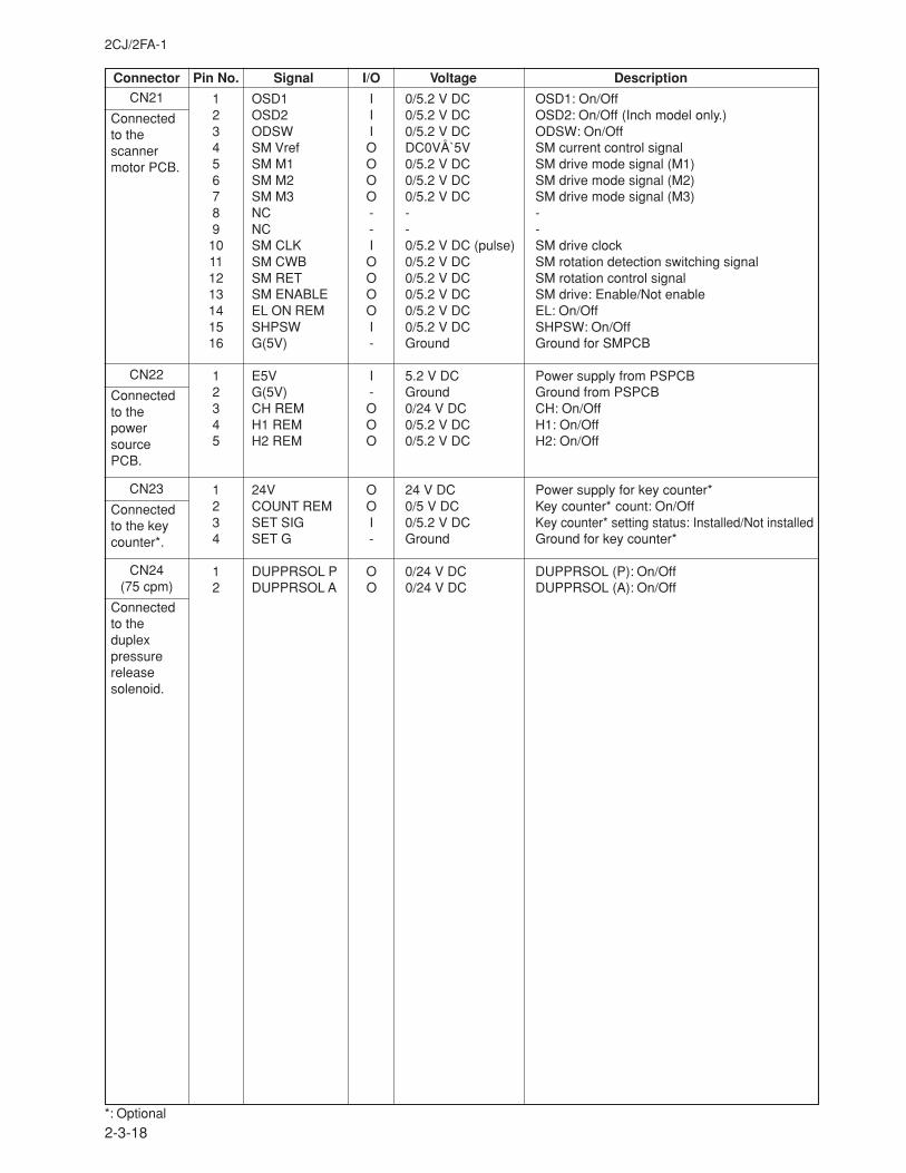
2CJ/2FA-1
2-3-18
Connector Pin No. Signal I/O Voltage DescriptionCN21
Connectedto thescannermotor PCB.
CN22
Connectedto thepowersourcePCB.
CN23
Connectedto the keycounter*.
CN24(75 cpm)
Connectedto theduplexpressurereleasesolenoid.
1 OSD1 I 0/5.2 V DC OSD1: On/Off2 OSD2 I 0/5.2 V DC OSD2: On/Off (Inch model only.)3 ODSW I 0/5.2 V DC ODSW: On/Off4 SM Vref O DC0VÅ`5V SM current control signal5 SM M1 O 0/5.2 V DC SM drive mode signal (M1)6 SM M2 O 0/5.2 V DC SM drive mode signal (M2)7 SM M3 O 0/5.2 V DC SM drive mode signal (M3)8 NC - - -9 NC - - -
10 SM CLK I 0/5.2 V DC (pulse) SM drive clock11 SM CWB O 0/5.2 V DC SM rotation detection switching signal12 SM RET O 0/5.2 V DC SM rotation control signal13 SM ENABLE O 0/5.2 V DC SM drive: Enable/Not enable14 EL ON REM O 0/5.2 V DC EL: On/Off15 SHPSW I 0/5.2 V DC SHPSW: On/Off16 G(5V) - Ground Ground for SMPCB
1 E5V I 5.2 V DC Power supply from PSPCB2 G(5V) - Ground Ground from PSPCB3 CH REM O 0/24 V DC CH: On/Off4 H1 REM O 0/5.2 V DC H1: On/Off5 H2 REM O 0/5.2 V DC H2: On/Off
1 24V O 24 V DC Power supply for key counter*2 COUNT REM O 0/5 V DC Key counter* count: On/Off3 SET SIG I 0/5.2 V DC Key counter* setting status: Installed/Not installed4 SET G - Ground Ground for key counter*
1 DUPPRSOL P O 0/24 V DC DUPPRSOL (P): On/Off2 DUPPRSOL A O 0/24 V DC DUPPRSOL (A): On/Off
*: Optional
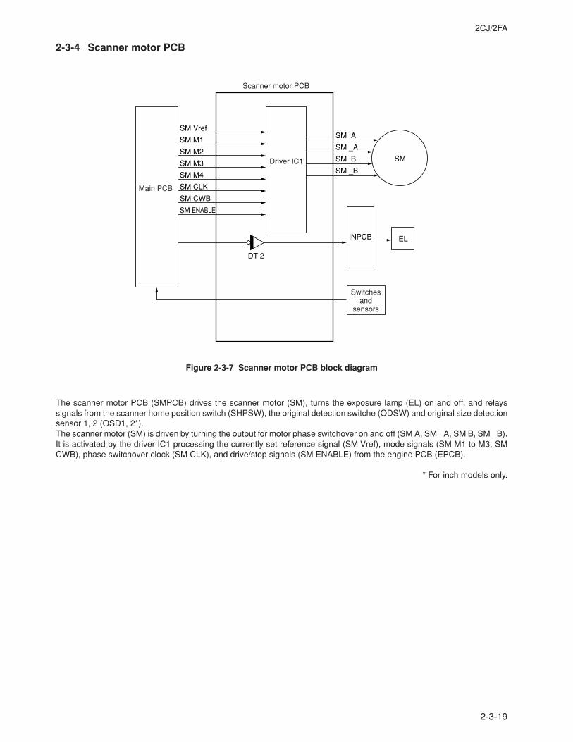
2CJ/2FA
2-3-19
2-3-4 Scanner motor PCB
Scanner motor PCB
Main PCB
Switches and
sensors
Driver IC1
SM Vref
SM M1SM A
SM _A
SM B
SM _B
SM M2
DT 2
INPCB EL
SMSM M3
SM M4
SM CLK
SM CWB
SM ENABLE
Figure 2-3-7 Scanner motor PCB block diagram
The scanner motor PCB (SMPCB) drives the scanner motor (SM), turns the exposure lamp (EL) on and off, and relayssignals from the scanner home position switch (SHPSW), the original detection switche (ODSW) and original size detectionsensor 1, 2 (OSD1, 2*).The scanner motor (SM) is driven by turning the output for motor phase switchover on and off (SM A, SM _A, SM B, SM _B).It is activated by the driver IC1 processing the currently set reference signal (SM Vref), mode signals (SM M1 to M3, SMCWB), phase switchover clock (SM CLK), and drive/stop signals (SM ENABLE) from the engine PCB (EPCB).
* For inch models only.
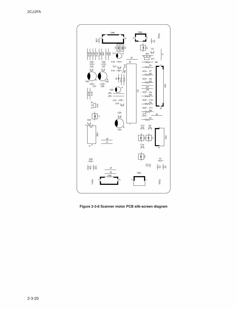
2CJ/2FA
2-3-20
FG
(2)
TP
1
L1L3L4
CN
7
16
C2
C3
FG
(1)
11 3
CN5
C1
C14
C13
C12
C11
C10
C9
C8
C7
C6
R7
R6
R5
R4
R3
R2
R1
R8
CN2
CN
3
C35
C33
1 1
16
IC1
1
CN
1
2
56C
36
J5
J4
J6
C20
C23
C16
C31 C26
C22
C25C30
C32 C27
C29 C24
C21
C19
C18
CN6 CN4
C17
C4
JP3
DT1E C B
1 6 3 1
C15
C34
JP4
J3
JP5
J2
JP2JP1
J7L7
DT
2
D1
R10
R9
22
JP13
JP14
JP12
JP11
JP10
JP9
JP8
C28
L5
C5
L2
J1
L6
JP7
JP6
JP15
BC
E
6
FG
(3)
Figure 2-3-8 Scanner motor PCB silk-screen diagram
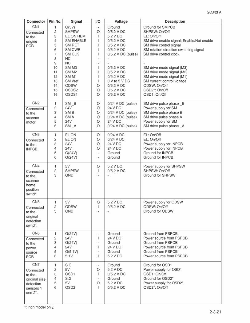
2CJ/2FA
2-3-21
Connector Pin No. Signal I/O Voltage Description
1 G(5V) - Ground Ground for SMPCB2 SHPSW O 0/5.2 V DC SHPSW: On/Off3 EL ON REM I 5.2 V DC EL: On/Off4 SM ENABLE I 0/5.2 V DC SM drive enable signal: Enable/Not enable5 SM RET I 0/5.2 V DC SM drive control signal6 SM CWB I 0/5.2 V DC SM rotation direction switching signal7 SM CLK I 0/5.2 V DC (pulse) SM drive control clock8 NC - - -9 NC - - -10 SM M3 I 0/5.2 V DC SM drive mode signal (M3)11 SM M2 I 0/5.2 V DC SM drive mode signal (M2)12 SM M1 I 0/5.2 V DC SM drive mode signal (M1)13 SM Vref I 0 V to 5 V DC SM current control voltage14 ODSW O 0/5.2 V DC ODSW: On/Off15 OSDS2 O 0/5.2 V DC OSD2*: On/Off16 OSDS1 O 0/5.2 V DC OSD1: On/Off
1 SM _B O 0/24 V DC (pulse) SM drive pulse phase _B2 24V O 24 V DC Power supply for SM3 SM B O 0/24 V DC (pulse) SM drive pulse phase B4 SM A O 0/24 V DC (pulse) SM drive pulse phase A5 24V O 24 V DC Power supply for SM6 SM _A O 0/24 V DC (pulse) SM drive pulse phase _A
1 EL ON O 0/24 V DC EL: On/Off2 EL ON O 0/24 V DC EL: On/Off3 24V O 24 V DC Power supply for INPCB4 24V O 24 V DC Power supply for INPCB5 G(24V) - Ground Ground for INPCB6 G(24V) - Ground Ground for INPCB
1 5V O 5.2 V DC Power supply for SHPSW2 SHPSW I 0/5.2 V DC SHPSW: On/Off3 GND - - Ground for SHPSW
1 5V O 5.2 V DC Power supply for ODSW2 ODSW I 0/5.2 V DC ODSW: On/Off3 GND - - Ground for ODSW
1 G(24V) - Ground Ground from PSPCB2 24V I 24 V DC Power source from PSPCB3 G(24V) - Ground Ground from PSPCB4 24V I 24 V DC Power source from PSPCB5 G(5.1V) - Ground Ground from PSPCB6 5.1V I 5.2 V DC Power source from PSPCB
1 S.G - Ground Ground for OSD12 5V O 5.2 V DC Power supply for OSD13 OSD1 I 0/5.2 V DC OSD1: On/Off4 S.G - Ground Ground for OSD2*5 5V O 5.2 V DC Power supply for OSD2*6 OSD2 I 0/5.2 V DC OSD2*: On/Off
CN1
Connectedto theenginePCB.
CN2
Connectedto thescannermotor.
CN3
Connectedto theINPCB.
CN4
Connectedto thescannerhomepositionswitch.
CN5
Connectedto theoriginaldetectionswitch.
CN6
Connectedto thepowersourcePCB.
CN7
Connectedto theoriginal sizedetectionsensors 1and 2*.
*: Inch model only.
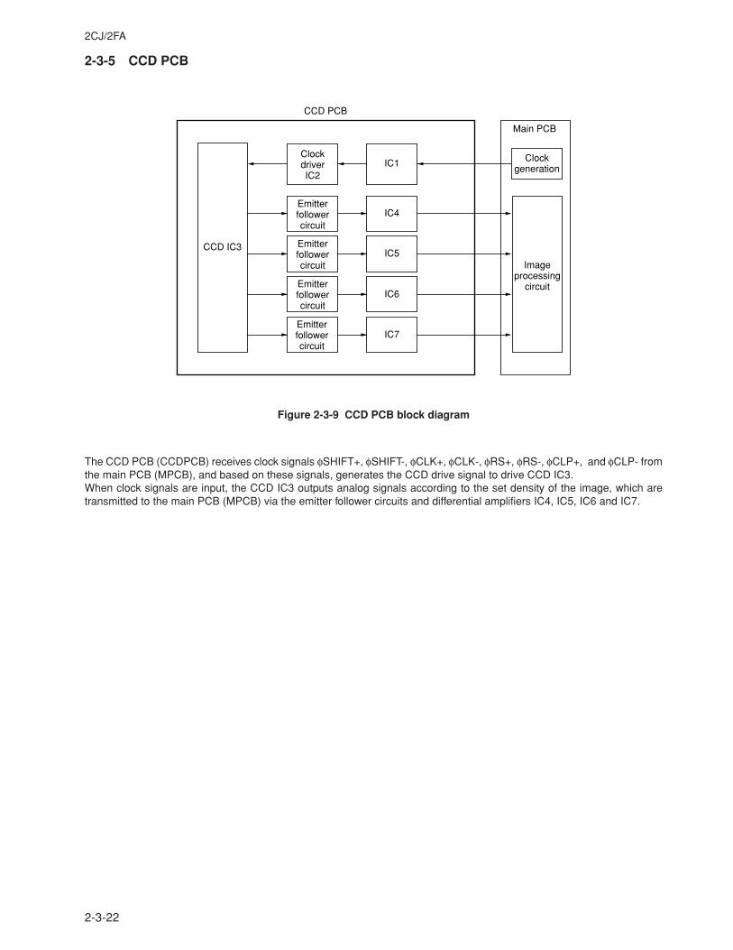
2CJ/2FA
2-3-22
2-3-5 CCD PCB
Emitter follower circuit
Emitter follower circuit
Emitter follower circuit
Emitter follower circuit
Clockdriver IC2
IC1
IC4
IC5
IC6
IC7
CCD IC3
Main PCB
CCD PCB
Clockgeneration
Imageprocessing
circuit
Figure 2-3-9 CCD PCB block diagram
The CCD PCB (CCDPCB) receives clock signals φSHIFT+, φSHIFT-, φCLK+, φCLK-, φRS+, φRS-, φCLP+, and φCLP- fromthe main PCB (MPCB), and based on these signals, generates the CCD drive signal to drive CCD IC3.When clock signals are input, the CCD IC3 outputs analog signals according to the set density of the image, which aretransmitted to the main PCB (MPCB) via the emitter follower circuits and differential amplifiers IC4, IC5, IC6 and IC7.
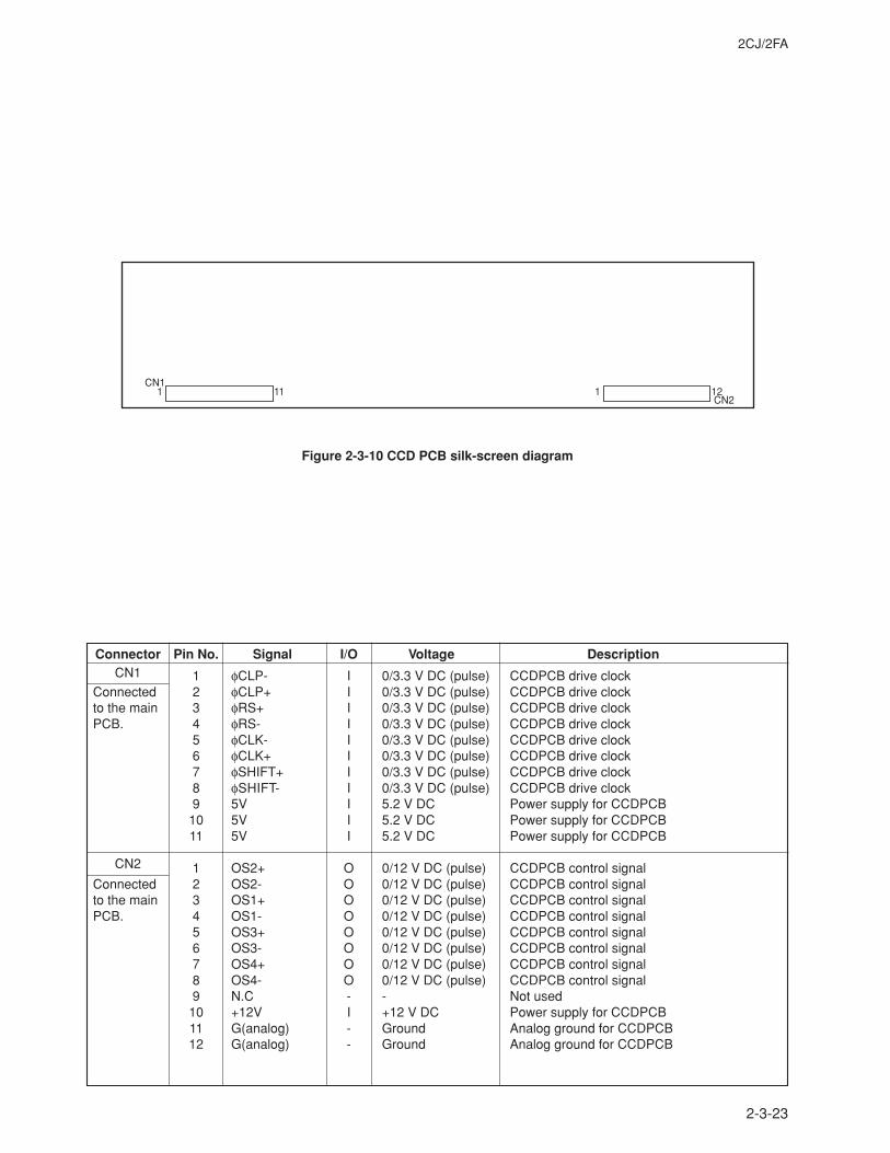
2CJ/2FA
2-3-23
Connector Pin No. Signal I/O Voltage DescriptionCN1
Connectedto the mainPCB.
CN2
Connectedto the mainPCB.
1 φCLP- I 0/3.3 V DC (pulse) CCDPCB drive clock2 φCLP+ I 0/3.3 V DC (pulse) CCDPCB drive clock3 φRS+ I 0/3.3 V DC (pulse) CCDPCB drive clock4 φRS- I 0/3.3 V DC (pulse) CCDPCB drive clock5 φCLK- I 0/3.3 V DC (pulse) CCDPCB drive clock6 φCLK+ I 0/3.3 V DC (pulse) CCDPCB drive clock7 φSHIFT+ I 0/3.3 V DC (pulse) CCDPCB drive clock8 φSHIFT- I 0/3.3 V DC (pulse) CCDPCB drive clock9 5V I 5.2 V DC Power supply for CCDPCB
10 5V I 5.2 V DC Power supply for CCDPCB11 5V I 5.2 V DC Power supply for CCDPCB
1 OS2+ O 0/12 V DC (pulse) CCDPCB control signal2 OS2- O 0/12 V DC (pulse) CCDPCB control signal3 OS1+ O 0/12 V DC (pulse) CCDPCB control signal4 OS1- O 0/12 V DC (pulse) CCDPCB control signal5 OS3+ O 0/12 V DC (pulse) CCDPCB control signal6 OS3- O 0/12 V DC (pulse) CCDPCB control signal7 OS4+ O 0/12 V DC (pulse) CCDPCB control signal8 OS4- O 0/12 V DC (pulse) CCDPCB control signal9 N.C - - Not used
10 +12V I +12 V DC Power supply for CCDPCB11 G(analog) - Ground Analog ground for CCDPCB12 G(analog) - Ground Analog ground for CCDPCB
CN1
CN21 11 1 12
Figure 2-3-10 CCD PCB silk-screen diagram
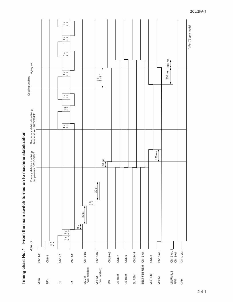
2CJ/2FA-1
2-4-1
Tim
ing
ch
art
No
. 1F
rom
th
e m
ain
sw
itch
tu
rned
on
to
mac
hin
e st
abili
zati
on
MS
WC
N11
-2
DB
RE
M
CB
RE
M
BE
LT F
BB
RE
M
PR
Y
EL
RE
M
MC
RE
M
LSU
FM
1, 2
CF
M
MS
W: O
nP
rimar
y st
abili
zatio
n fix
ing
tem
pera
ture
165
°C/3
29°F
Sec
onda
ry s
tabi
lizat
ion
fixin
g te
mpe
ratu
re 1
90°C
/374
°FA
ging
end
Cop
ying
ena
bled
1 s
1 s
1 s
1 s
1 s
1 s
1 s
3 s
2 m
in*
*: F
or 7
5 cp
m m
odel
2 s
1 s
1 s
1 s
3 s
20 s
20 s
100
ms 10
0 m
s
200
ms
300
ms
CN
9-4
H1
CN
12-1
H2
CN
12-2
MC
CM
(Fw
d. r
otat
ion)
CN
13-B
6
MC
CM
(Rev
. rot
atio
n)C
N13
-B7
IFM
CN
21-A
3
CN
5-7
CN
5-9
CN
21-1
4
CN
12-A
11
CN
5-3
MC
FM
CN
12-A
2
CN
12-A
4, 5
FF
MC
N12
-A1
CN
12-A
3
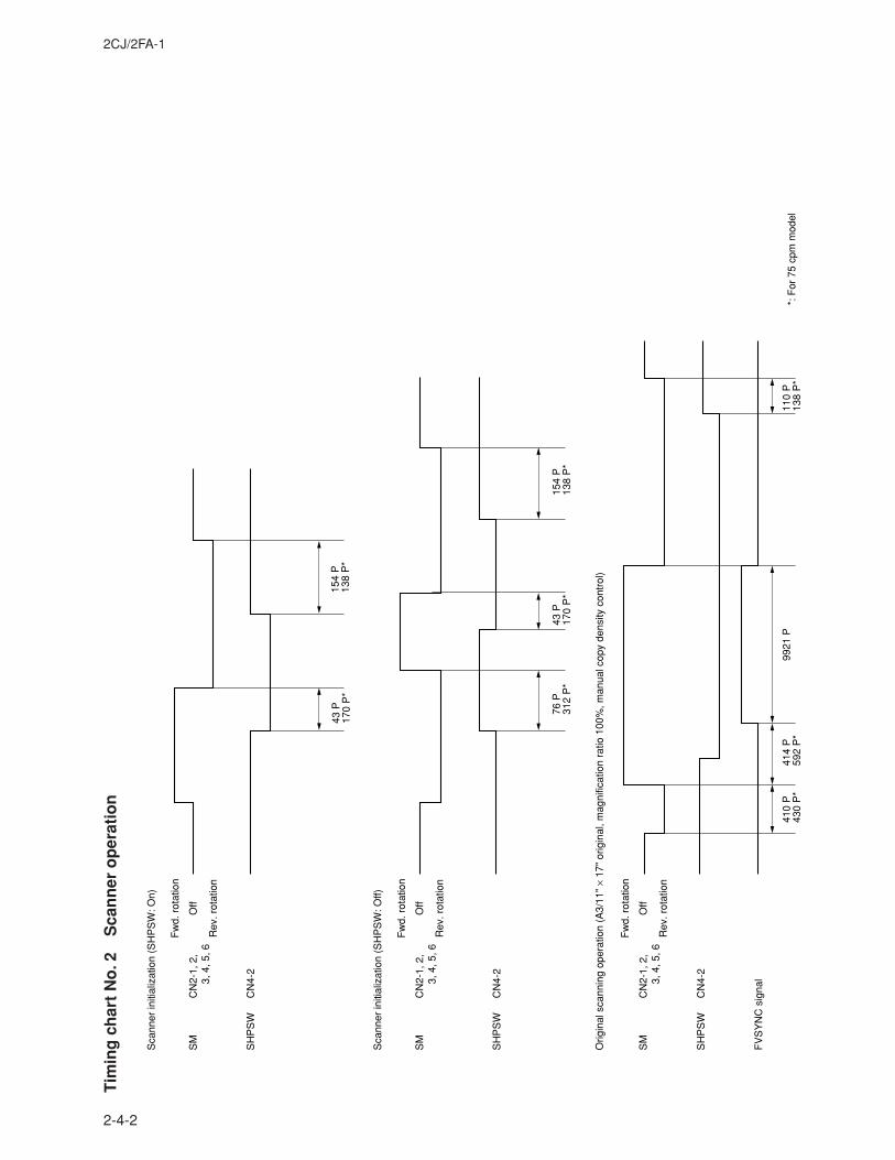
2CJ/2FA-1
2-4-2
Tim
ing
ch
art
No
. 2S
can
ner
op
erat
ion
43 P
170
P*
SM
Off
Fw
d. r
otat
ion
Sca
nner
initi
aliz
atio
n (S
HP
SW
: On)
Rev
. rot
atio
n
CN
2-1,
2,
3
, 4, 5
, 6
SH
PS
WC
N4-
2
SM
Off
Fw
d. r
otat
ion
Sca
nner
initi
aliz
atio
n (S
HP
SW
: Off)
Orig
inal
sca
nnin
g op
erat
ion
(A3/
11"
× 17
" or
igin
al, m
agni
ficat
ion
ratio
100
%, m
anua
l cop
y de
nsity
con
trol
)
Rev
. rot
atio
n
CN
2-1,
2,
3
, 4, 5
, 6
SH
PS
WC
N4-
2
SM
Off
Fw
d. r
otat
ion
Rev
. rot
atio
n
CN
2-1,
2,
3
, 4, 5
, 6
SH
PS
WC
N4-
2
FV
SY
NC
sig
nal
154
P13
8 P
*
43 P
170
P*
76 P
312
P*
410
P43
0 P
*41
4 P
592
P*
110
P13
8 P
*99
21 P
154
P13
8 P
*
*: F
or 7
5 cp
m m
odel
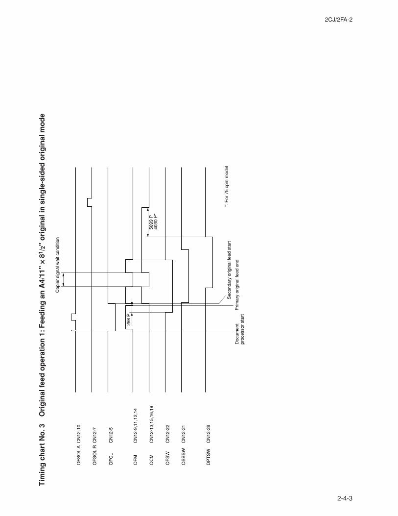
2CJ/2FA-2
2-4-3
Tim
ing
ch
art
No
. 3O
rig
inal
fee
d o
per
atio
n 1
: Fee
din
g a
n A
4/11
" ×××× ×
81/ 2
" o
rig
inal
in s
ing
le-s
ided
ori
gin
al m
od
e
Cop
ier
sign
al w
ait c
ondi
tion
298
P
5099
P40
30 P
*
Sec
onda
ry o
rigin
al fe
ed s
tart
Prim
ary
orig
inal
feed
end
Doc
umen
tpr
oces
sor
star
t
OF
MC
N12
-9,1
1,12
,14
OC
MC
N12
-13,
15,1
6,18
OF
SW
C
N12
-22
OS
BS
WC
N12
-21
OF
SO
L A
DP
TS
W
CN
12-1
0
OF
SO
L R
CN
12-7
OF
CL
CN
12-5
CN
12-2
9
*: F
or 7
5 cp
m m
odel
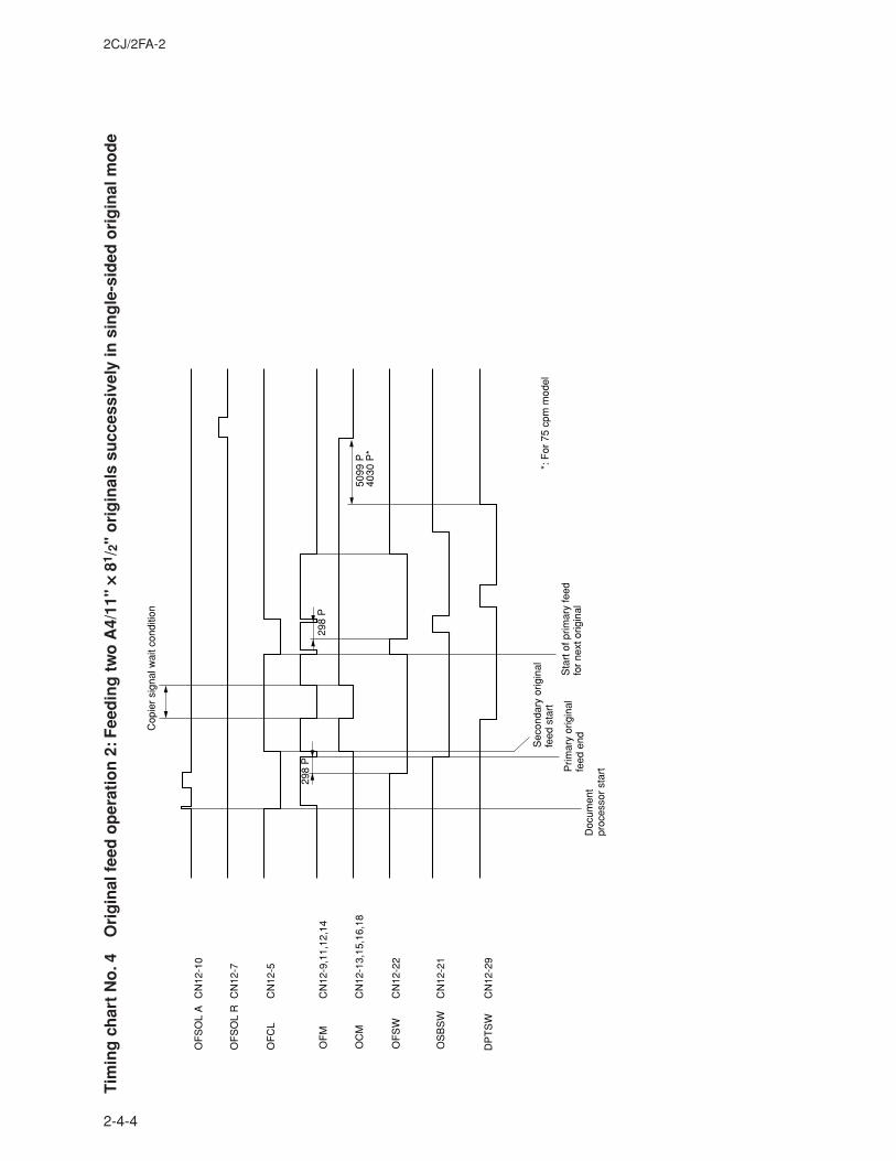
2CJ/2FA-2
2-4-4
Tim
ing
ch
art
No
. 4O
rig
inal
fee
d o
per
atio
n 2
: Fee
din
g t
wo
A4/
11"
×××× × 81
/ 2"
ori
gin
als
succ
essi
vely
in s
ing
le-s
ided
ori
gin
al m
od
e
Sec
onda
ry o
rigin
al
feed
sta
rt
Sta
rt o
f prim
ary
feed
fo
r ne
xt o
rigin
alP
rimar
y or
igin
al
feed
end
Doc
umen
tpr
oces
sor
star
t
OF
M
OF
SO
L A
CN
12-1
0
OF
SO
L R
CN
12-7
OF
CL
CN
12-5
DP
TS
W
Cop
ier
sign
al w
ait c
ondi
tion
298
P
298
P
5099
P40
30 P
*
OS
BS
W
CN
12-9
,11,
12,1
4
OC
MC
N12
-13,
15,1
6,18
OF
SW
CN
12-2
2
CN
12-2
1
CN
12-2
9
*: F
or 7
5 cp
m m
odel
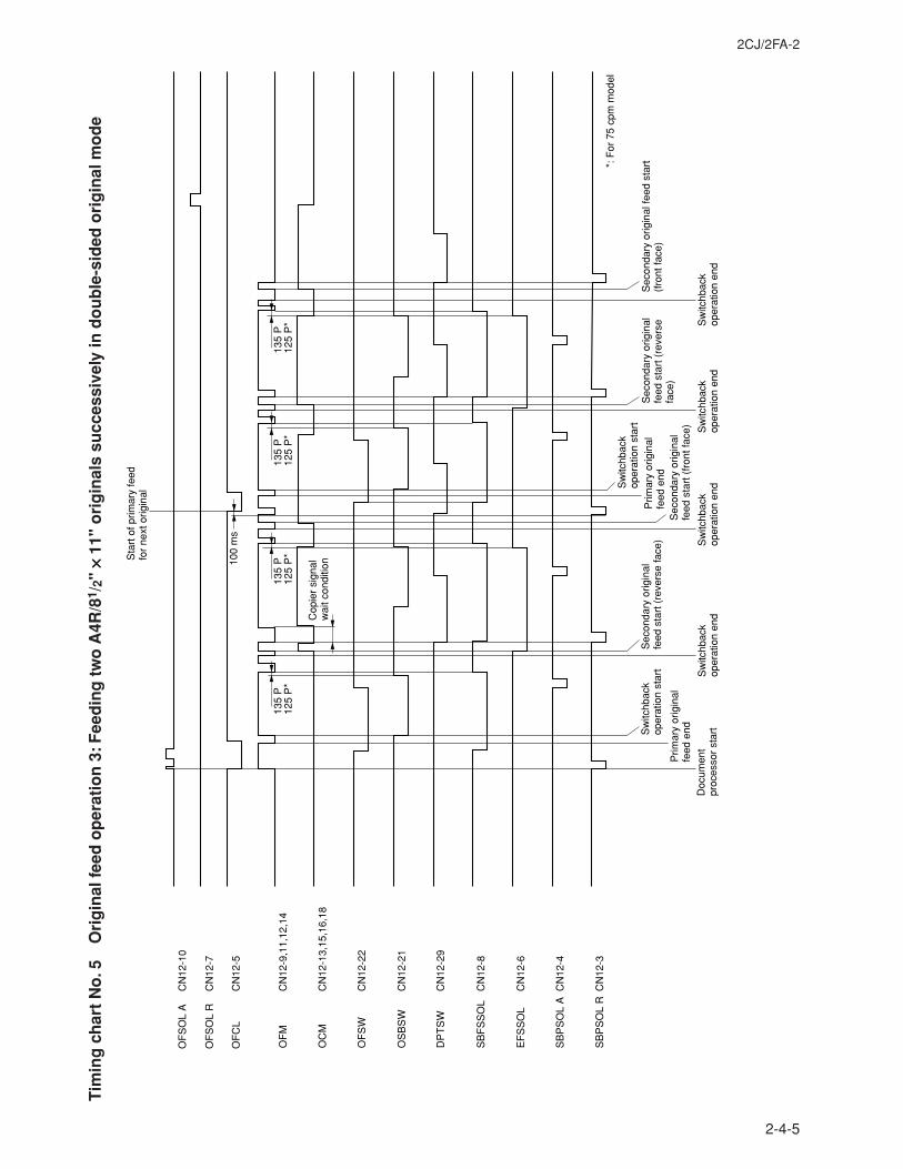
2CJ/2FA-2
2-4-5
Tim
ing
ch
art
No
. 5O
rig
inal
fee
d o
per
atio
n 3
: Fee
din
g t
wo
A4R
/81 /
2" ×××× ×
11"
ori
gin
als
succ
essi
vely
in d
ou
ble
-sid
ed o
rig
inal
mo
de
Sec
onda
ry o
rigin
al
feed
sta
rt (
reve
rse
face
)S
econ
dary
orig
inal
fe
ed s
tart
(re
vers
e fa
ce)
Sec
onda
ry o
rigin
al
feed
sta
rt (
fron
t fac
e)
Sec
onda
ry o
rigin
al fe
ed s
tart
(f
ront
face
)S
witc
hbac
k op
erat
ion
star
t
Sw
itchb
ack
oper
atio
n st
art
Sw
itchb
ack
oper
atio
n en
dS
witc
hbac
k op
erat
ion
end
Sw
itchb
ack
oper
atio
n en
dS
witc
hbac
k op
erat
ion
end
Sta
rt o
f prim
ary
feed
fo
r ne
xt o
rigin
al
Prim
ary
orig
inal
fe
ed e
nd
Prim
ary
orig
inal
fe
ed e
nd
Doc
umen
tpr
oces
sor
star
t
Cop
ier
sign
al
wai
t con
ditio
n
OF
M
100
ms
135
P12
5 P
*13
5 P
125
P*
135
P12
5 P
*13
5 P
125
P*
OF
SO
L A
CN
12-1
0
OF
SO
L R
CN
12-7
OF
CL
CN
12-5
CN
12-9
,11,
12,1
4
OC
M
CN
12-1
3,15
,16,
18
OF
SW
C
N12
-22
OS
BS
WC
N12
-21
DP
TS
WC
N12
-29
SB
FS
SO
LC
N12
-8
EF
SS
OL
CN
12-6
SB
PS
OL
AC
N12
-4
SB
PS
OL
RC
N12
-3*:
For
75
cpm
mod
el
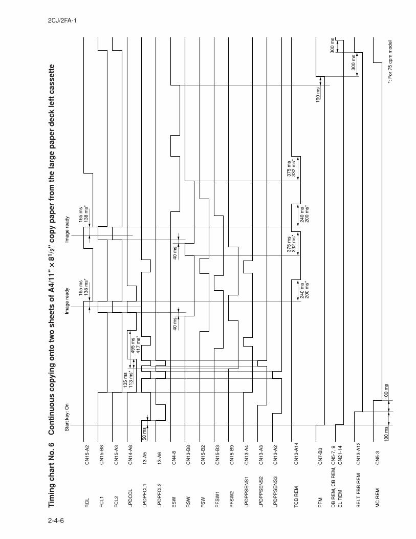
2CJ/2FA-1
2-4-6
Tim
ing
ch
art
No
. 6C
on
tin
uo
us
cop
yin
g o
nto
tw
o s
hee
ts o
f A
4/11
" ×××× ×
81/ 2
" co
py
pap
er f
rom
th
e la
rge
pap
er d
eck
left
cas
sett
e
165
ms
138
ms*
135
ms
113
ms*
495
ms
417
ms*
165
ms
138
ms*
100
ms
100
ms
190
ms
300
ms
300
ms
50 m
s
40 m
s40
ms
Sta
rt k
ey: O
nIm
age
read
yIm
age
read
y
CN
15-A
2R
CL
CN
15-B
8F
CL1
CN
15-A
3F
CL2
CN
14-A
8LP
DC
CL
13-A
5LP
DP
FC
L1
13-A
6LP
DP
FC
L2
CN
4-8
ES
W
CN
13-B
8R
SW
CN
15-B
2F
SW
CN
15-B
3P
FS
W1
CN
15-B
9P
FS
W2
CN
13-A
4LP
DP
PS
EN
S1
CN
13-A
3LP
DP
PS
EN
S2
CN
13-A
2LP
DP
PS
EN
S3
CN
13-A
14T
CB
RE
M
CN
7-B
3P
FM
CN
5-7,
9D
B R
EM
, CB
RE
M,
CN
21-1
4E
L R
EM
CN
13-A
12B
ELT
FB
B R
EM
CN
5-3
MC
RE
M
240
ms
200
ms*
240
ms
200
ms*
375
ms
332
ms*
375
ms
332
ms*
*: F
or 7
5 cp
m m
odel
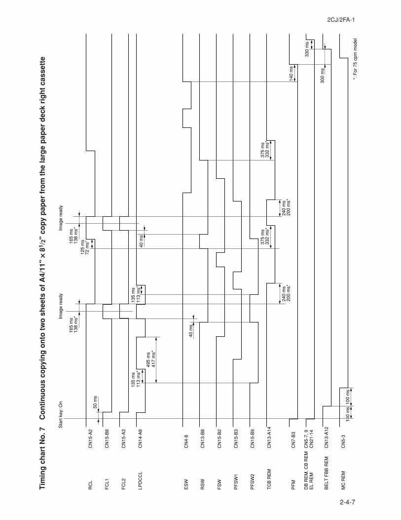
2CJ/2FA-1
2-4-7
Tim
ing
ch
art
No
. 7C
on
tin
uo
us
cop
yin
g o
nto
tw
o s
hee
ts o
f A
4/11
" ×××× ×
81/ 2
" co
py
pap
er f
rom
th
e la
rge
pap
er d
eck
rig
ht
cass
ette
Sta
rt k
ey: O
nIm
age
read
yIm
age
read
y
50 m
s
165
ms
138
ms*
165
ms
138
ms*
125
ms
72 m
s*
40 m
s
40 m
s
100
ms
140
ms
330
ms
300
ms
100
ms
RC
LC
N15
-A2
FC
L1C
N15
-B8
FC
L2C
N15
-A3
LPD
CC
LC
N14
-A8
ES
WC
N4-
8
RS
W
CN
13-B
8
FS
WC
N15
-B2
PF
SW
1C
N15
-B3
PF
SW
2C
N15
-B9
TC
B R
EM
CN
13-A
14
PF
MC
N7-
B3
DB
RE
M, C
B R
EM
CN
5-7,
9E
L R
EM
CN
21-1
4
BE
LT F
BB
RE
MC
N13
-A12
MC
RE
M
CN
5-3
240
ms
200
ms*
240
ms
200
ms*
375
ms
332
ms*
375
ms
332
ms*
*: F
or 7
5 cp
m m
odel
135
ms
113
ms*
135
ms
113
ms*
495
ms
417
ms*
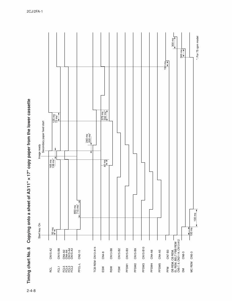
2CJ/2FA-1
2-4-8
Tim
ing
ch
art
No
. 8C
op
yin
g o
nto
a s
hee
t o
f A
3/11
" ×××× ×
17"
cop
y p
aper
fro
m t
he
low
er c
asse
tte
Sta
rt k
ey: O
nIm
age
read
yS
econ
dary
pap
er fe
ed s
tart
50 m
s
850
ms
715
ms*
125
ms
72 m
s*
165
ms
138
ms*
240
ms
200
ms*
40 m
s37
5 m
s33
2 m
s*
190
ms
300
ms
300
ms
100
ms
100
ms
RC
L
PF
CL-
L
CN
15-A
2
FC
L1C
N15
-B8
FC
L5C
N4-
A2
FC
L4C
N4-
A4
FC
L3C
N15
-A4
FC
L2C
N15
-A3
TC
B R
EM
CN
13-A
14
ES
WC
N4-
8
RS
WC
N13
-B8
FS
WC
N15
-B2
PF
SW
1C
N15
-B3
PF
SW
2C
N15
-B9
PF
SW
3C
N15
-B10
PF
SW
4C
N4-
A8
PF
SW
5C
N4-
A5
PF
MC
N7-
B3
DM
CN
8-3
MC
RE
MC
N5-
3
DB
RE
M, C
B R
EM
,E
L R
EM
, BE
LT F
BB
RE
M
CN
5-7,
9, C
N21
-14,
CN
13-A
12
CN
2-10
*: F
or 7
5 cp
m m
odel
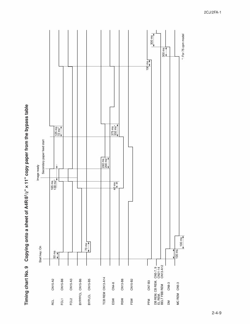
2CJ/2FA-1
2-4-9
Tim
ing
ch
art
No
. 9C
op
yin
g o
nto
a s
hee
t o
f A
4R/8
1 /2"
×××× × 1
1" c
op
y p
aper
fro
m t
he
byp
ass
tab
le
TC
B R
EM
CN
13-A
14
ES
WC
N4-
8
RS
WC
N13
-B8
FS
WC
N15
-B2
Sta
rt k
ey: O
nIm
age
read
y
Sec
onda
ry p
aper
feed
sta
rt
50 m
s 70 m
s
165
ms
138
ms*
125
ms
72 m
s*
240
ms
200
ms*
375
ms
332
ms*
40 m
s
100
ms
100
ms
190
ms
300
ms
300
ms
RC
L
DM
CN
8-3
MC
RE
MC
N5-
3
DB
RE
M, C
B R
EM
, C
N5-
7, 9
EL
RE
M,
CN
21-1
4B
ELT
FB
B R
EM
C
N13
-A12
PF
MC
N7-
B3
CN
15-A
2
FC
L1C
N15
-B8
FC
L2C
N15
-A3
BY
PP
FC
LC
N15
-B6
BY
PLC
LC
N15
-B5
*: F
or 7
5 cp
m m
odel
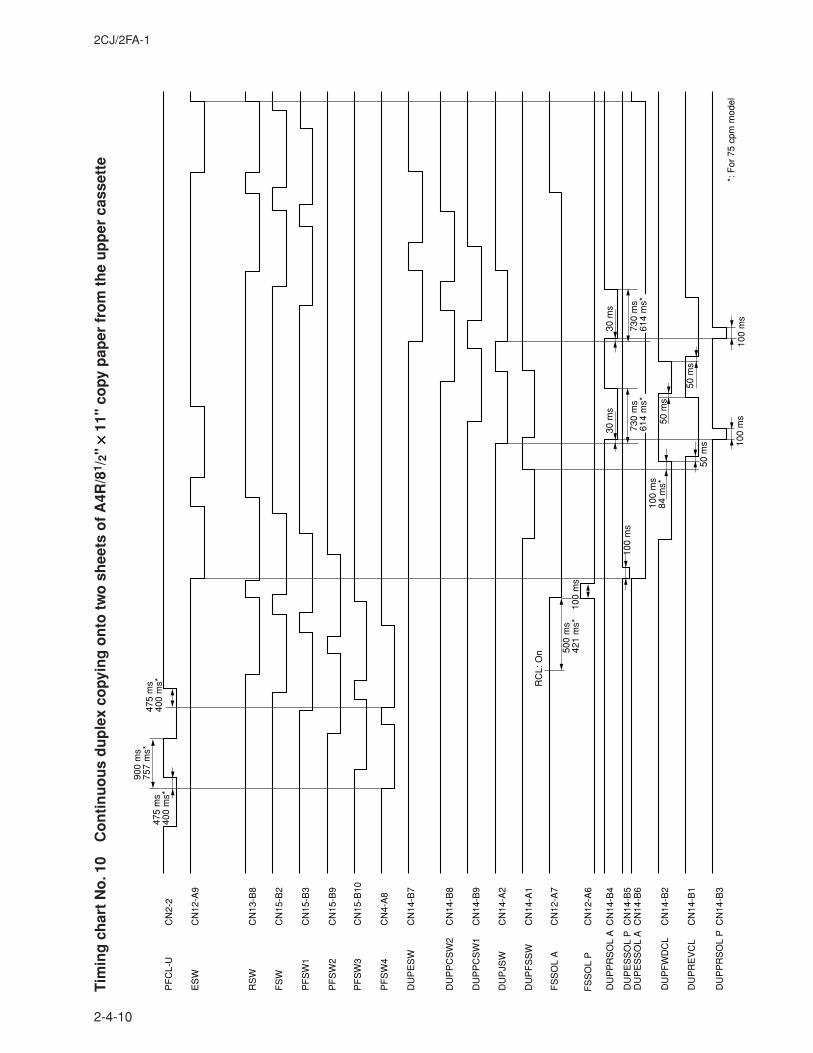
2CJ/2FA-1
2-4-10
Tim
ing
ch
art
No
. 10
Co
nti
nu
ou
s d
up
lex
copy
ing
on
to t
wo
sh
eets
of
A4R
/81 /
2" ×××× ×
11"
co
py p
aper
fro
m t
he
up
per
cas
sett
e
PF
CL-
U
ES
WC
N12
-A9
RS
WC
N13
-B8
FS
WC
N15
-B2
PF
SW
1C
N15
-B3
PF
SW
2C
N15
-B9
PF
SW
3C
N15
-B10
PF
SW
4C
N4-
A8
DU
PE
SW
CN
14-B
7
DU
PP
CS
W2
CN
14-B
8
DU
PP
CS
W1
CN
14-B
9
DU
PJS
WC
N14
-A2
DU
PF
SS
WC
N14
-A1
FS
SO
L A
CN
12-A
7
CN
2-2
FS
SO
L P
CN
12-A
6
DU
PP
RS
OL
AC
N14
-B4
DU
PE
SS
OL
PC
N14
-B5
DU
PE
SS
OL
AC
N14
-B6
DU
PF
WD
CL
CN
14-B
2
DU
PR
EV
CL
CN
14-B
1
DU
PP
RS
OL
PC
N14
-B3
900
ms
757
ms*
475
ms
400
ms*
475
ms
400
ms*
500
ms
421
ms*
100
ms
RC
L: O
n
100
ms
100
ms
84 m
s*
100
ms
50 m
s
30 m
s30
ms
50 m
s
50 m
s
100
ms
*: F
or 7
5 cp
m m
odel
730
ms
614
ms*
73
0 m
s61
4 m
s*
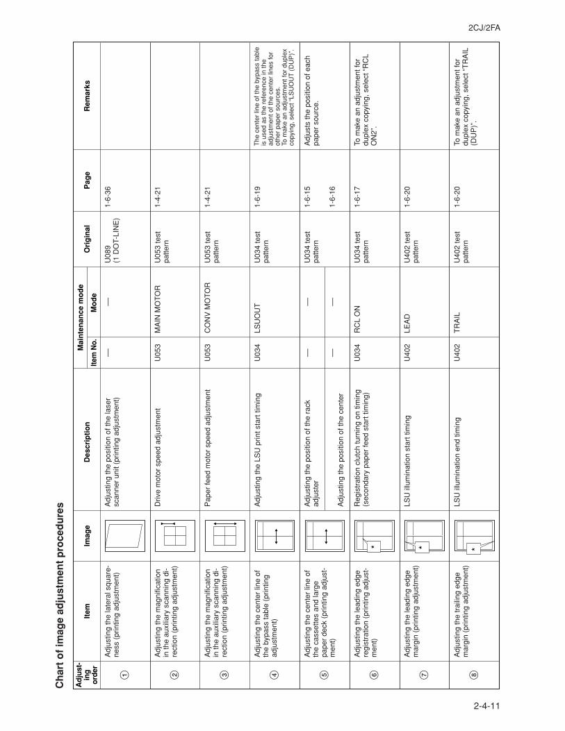
2CJ/2FA
2-4-11
Ch
art
of
imag
e ad
just
men
t p
roce
du
res
Item
Imag
eD
escr
ipti
on
Adj
ustin
g th
e po
sitio
n of
the
lase
r sc
anne
r un
it (p
rintin
g ad
just
men
t)A
djus
ting
the
late
ral s
quar
e-ne
ss (
prin
ting
adju
stm
ent)
––
1-6-
36––
Item
No.
Mo
de
Ori
gin
alP
age
Rem
arks
Mai
nte
nan
ce m
od
e
U08
9 (1
DO
T-LI
NE
)
Ad
just
-in
go
rder
1
Driv
e m
otor
spe
ed a
djus
tmen
tA
djus
ting
the
mag
nific
atio
n in
the
auxi
liary
sca
nnin
g di
-re
ctio
n (p
rintin
g ad
just
men
t)
MA
IN M
OT
OR
1-
4-21
U05
3U
053
test
pa
ttern
2
Adj
ustin
g th
e LS
U p
rint s
tart
tim
ing
Adj
ustin
g th
e ce
nter
line
of
the
bypa
ss ta
ble
(prin
ting
adju
stm
ent)
LSU
OU
TT
he c
ente
r lin
e of
the
bypa
ss ta
ble
is u
sed
as th
e re
fere
nce
in th
e ad
just
men
t of t
he c
ente
r lin
es fo
r ot
her
pape
r so
urce
s.To
mak
e an
adj
ustm
ent f
or d
uple
x co
pyin
g, s
elec
t “LS
UO
UT
(D
UP
)”.
1-6-
19U
034
U03
4 te
st
patte
rn4
Adj
ustin
g th
e ce
nter
line
of
the
cass
ette
s an
d la
rge
pape
r de
ck (
prin
ting
adju
st-
men
t)
–– ––
Adj
usts
the
posi
tion
of e
ach
pape
r so
urce
.1-
6-15
1-6-
16
–– ––
U03
4 te
st
patte
rn5
Reg
istr
atio
n cl
utch
turn
ing
on ti
min
g (s
econ
dary
pap
er fe
ed s
tart
tim
ing)
Adj
ustin
g th
e le
adin
g ed
ge
regi
stra
tion
(prin
ting
adju
st-
men
t)
RC
L O
NTo
mak
e an
adj
ustm
ent f
or
dupl
ex c
opyi
ng, s
elec
t “R
CL
ON
2”.
1-6-
17U
034
U03
4 te
st
patte
rn6
LSU
illu
min
atio
n st
art t
imin
gA
djus
ting
the
lead
ing
edge
m
argi
n (p
rintin
g ad
just
men
t)LE
AD
1-
6-20
U40
2U
402
test
pa
ttern
7
LSU
illu
min
atio
n en
d tim
ing
Adj
ustin
g th
e tr
ailin
g ed
ge
mar
gin
(prin
ting
adju
stm
ent)
TR
AIL
To m
ake
an a
djus
tmen
t for
du
plex
cop
ying
, sel
ect “
TR
AIL
(D
UP
)”.
1-6-
20
U40
2U
402
test
pa
ttern
8
Adj
ustin
g th
e po
sitio
n of
the
rack
ad
just
er
Adj
ustin
g th
e po
sitio
n of
the
cent
er
Pap
er fe
ed m
otor
spe
ed a
djus
tmen
tA
djus
ting
the
mag
nific
atio
n in
the
auxi
liary
sca
nnin
g di
-re
ctio
n (p
rintin
g ad
just
men
t)
CO
NV
MO
TO
R
1-4-
21U
053
U05
3 te
st
patte
rn3

2CJ/2FA-2
2-4-12
Item
Imag
eD
escr
ipti
on
Dat
a pr
oces
sing
Adj
ustin
g m
agni
ficat
ion
of
the
scan
ner
in th
e m
ain
scan
ning
dire
ctio
n (s
cann
ing
adju
stm
ent)
MA
IN S
CA
N A
DJ
No
adju
stm
ent f
or c
opyi
ng
usin
g th
e do
cum
ent
proc
esso
r.
1-6-
39U
065
Item
No.
Mo
de
Ori
gin
alP
age
Rem
arks
Mai
nte
nan
ce m
od
e
Test
cha
rt
Ad
just
-in
go
rder
!
Orig
inal
sca
nnin
g sp
eed
Adj
ustin
g m
agni
ficat
ion
of
the
scan
ner
in th
e au
xilia
ry
scan
ning
dire
ctio
n (s
cann
ing
adju
stm
ent)
SU
B S
CA
N A
DJ
––U
065:
For
cop
ying
an
orig
inal
pl
aced
on
the
cont
act g
lass
.U
070:
For
cop
ying
orig
inal
s fr
om th
e do
cum
ent p
roce
ssor
.
1-6-
40
1-
6-78
U06
5U
070
Test
cha
rt
@
Orig
inal
sca
n st
art t
imin
gA
djus
ting
the
lead
ing
edge
re
gist
ratio
n (s
cann
ing
ad-
just
men
t)
AD
JUS
T D
ATA
LEA
D E
DG
E A
DJ
U06
6: F
or c
opyi
ng a
n or
igin
al
plac
ed o
n th
e co
ntac
t gla
ss.
U07
1: F
or c
opyi
ng o
rigin
als
from
the
docu
men
t pro
cess
or.
1-6-
42
1-
6-80
U06
6U
071
Test
cha
rt
$
Adj
ustin
g th
e ce
nter
line
(s
cann
ing
adju
stm
ent)
AD
JUS
T D
ATA
––U
067:
For
cop
ying
an
orig
inal
pl
aced
on
the
cont
act g
lass
.U
072:
For
cop
ying
orig
inal
s fr
om th
e do
cum
ent p
roce
ssor
.
1-6-
411-
6-79
U06
7U
072
Test
cha
rt
#
Adj
ustin
g th
e or
igin
al s
can
data
(im
age
adju
stm
ent)
Adj
ustin
g th
e le
adin
g ed
ge
mar
gin
(sca
nnin
g ad
just
-m
ent)
B M
AR
GIN
B M
AR
GIN
U40
3: F
or c
opyi
ng a
n or
igin
al
plac
ed o
n th
e co
ntac
t gla
ss.
U40
4: F
or c
opyi
ng o
rigin
als
from
the
docu
men
t pro
cess
or.
1-6-
43
1-
6-82
U40
3U
404
Test
cha
rt
%
Adj
ustin
g th
e or
igin
al s
can
data
(im
age
adju
stm
ent)
Adj
ustin
g th
e tr
ailin
g ed
ge
mar
gin
(sca
nnin
g ad
just
-m
ent)
D M
AR
GIN
D M
AR
GIN
U40
3: F
or c
opyi
ng a
n or
igin
al
plac
ed o
n th
e co
ntac
t gla
ss.
U40
4: F
or c
opyi
ng o
rigin
als
from
the
docu
men
t pro
cess
or.
1-6-
43
1-
6-82
U40
3U
404
Test
cha
rt
^
Adj
ustin
g th
e or
igin
al s
can
data
(im
age
adju
stm
ent)
LSU
illu
min
atio
n st
art/e
nd ti
min
gA
djus
ting
the
left
and
right
m
argi
ns (
prin
ting
adju
st-
men
t)
A/C
1-
6-20
U40
2U
402
test
pa
ttern
9
Adj
ustin
g th
e po
sitio
n of
the
ISU
(sc
ann-
ing
adju
stm
ent)
Adj
ustin
g th
e la
tera
l squ
are-
ness
(sc
anni
ng a
djus
tmen
t)––
1-
6-38
––Te
st c
hart
0
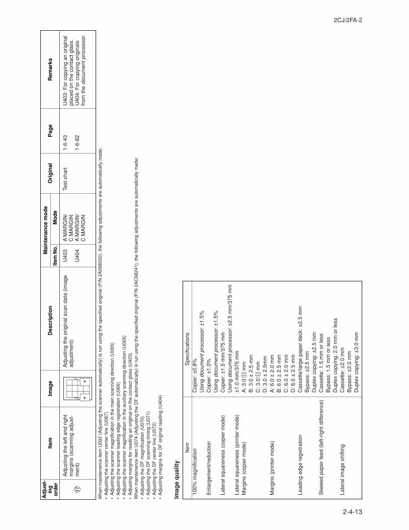
2CJ/2FA-2
2-4-13
Whe
n m
aint
enan
ce it
em U
092
(Adj
ustin
g th
e sc
anne
r au
tom
atic
ally
) is
run
usi
ng th
e sp
ecifi
ed o
rigin
al (
P/N
2A
0680
20),
the
follo
win
g ad
just
men
ts a
re a
utom
atic
ally
mad
e:•
Adj
ustin
g th
e sc
anne
r ce
nter
line
(U
067)
•A
djus
ting
the
scan
ner
mag
nific
atio
n in
the
mai
n sc
anni
ng d
irect
ion
(U06
5)•
Adj
ustin
g th
e sc
anne
r le
adin
g ed
ge r
egis
trat
ion
(U06
6)•
Adj
ustin
g th
e sc
anne
r m
agni
ficat
ion
in th
e au
xilia
ry s
cann
ing
dire
ctio
n (U
065)
•A
djus
ting
mar
gins
for
read
ing
an o
rigin
al o
n th
e co
ntac
t gla
ss (
U40
3)W
hen
mai
nten
ance
item
U07
4 (A
djus
ting
the
DF
aut
omat
ical
ly)
is r
un u
sing
the
spec
ified
orig
inal
(P
/N 2
AC
6824
1), t
he fo
llow
ing
adju
stm
ents
are
aut
omat
ical
ly m
ade:
•A
djus
ting
the
DF
mag
nific
atio
n (U
070)
•A
djus
ting
the
DF
sca
nnin
g tim
ing
(U07
1)•
Adj
ustin
g th
e D
F c
ente
r lin
e (U
072)
•A
djus
ting
mar
gins
for
DF
orig
inal
rea
ding
(U
404)
Item
Imag
eD
escr
ipti
on
Item
No.
Mo
de
Ori
gin
alP
age
Rem
arks
Mai
nte
nan
ce m
od
eA
dju
st-
ing
ord
er
Adj
ustin
g th
e or
igin
al s
can
data
(im
age
adju
stm
ent)
Adj
ustin
g th
e le
ft an
d rig
ht
mar
gins
(sc
anni
ng a
djus
t-m
ent)
A M
AR
GIN
/C
MA
RG
INA
MA
RG
IN/
C M
AR
GIN
U40
3: F
or c
opyi
ng a
n or
igin
al
plac
ed o
n th
e co
ntac
t gla
ss.
U40
4: F
or c
opyi
ng o
rigin
als
from
the
docu
men
t pro
cess
or.
1-6-
43
1-6-
82
U40
3
U40
4
Test
cha
rt
&
Imag
e q
ual
ity
Item
Spe
cific
atio
ns10
0% m
agni
ficat
ion
Cop
ier:
±0.
8%U
sing
doc
umen
t pro
cess
or: ±
1.5%
Enl
arge
men
t/red
uctio
nC
opie
r: ±
1.0%
Usi
ng d
ocum
ent p
roce
ssor
: ±1.
5%La
tera
l squ
aren
ess
(cop
ier
mod
e)C
opie
r: ±
1.5
mm
/375
mm
Usi
ng d
ocum
ent p
roce
ssor
: ±2.
5 m
m/3
75 m
mLa
tera
l squ
aren
ess
(prin
ter
mod
e)±
1.0
mm
/375
mm
Mar
gins
(co
pier
mod
e)A
: 3.0
+2.
0 mm
B: 3
.0 ±
2.5
mm
C: 3
.0+
2.0 m
mD
: 3.0
± 2
.5m
mM
argi
ns (
prin
ter
mod
e)A
: 6.0
± 2
.0 m
mB
: 6.0
± 2
.5 m
mC
: 6.0
± 2
.0 m
mD
: 6.0
± 2
.5 m
mLe
adin
g ed
ge r
egis
trat
ion
Cas
sette
/larg
e pa
per
deck
: ±2.
5 m
mB
ypas
s: ±
2.5
mm
Dup
lex
copy
ing:
±2.
5 m
mS
kew
ed p
aper
feed
(le
ft-rig
ht d
iffer
ence
)C
asse
tte: 1
.5 m
m o
r le
ssB
ypas
s: 1
.5 m
m o
r le
ssD
uple
x co
pyin
g: 2
.0 m
m o
r le
ssLa
tera
l im
age
shift
ing
Cas
sette
: ±2.
0 m
mB
ypas
s: ±
2.0
mm
Dup
lex
copy
ing:
±3.
0 m
m
–2.0
–2.0
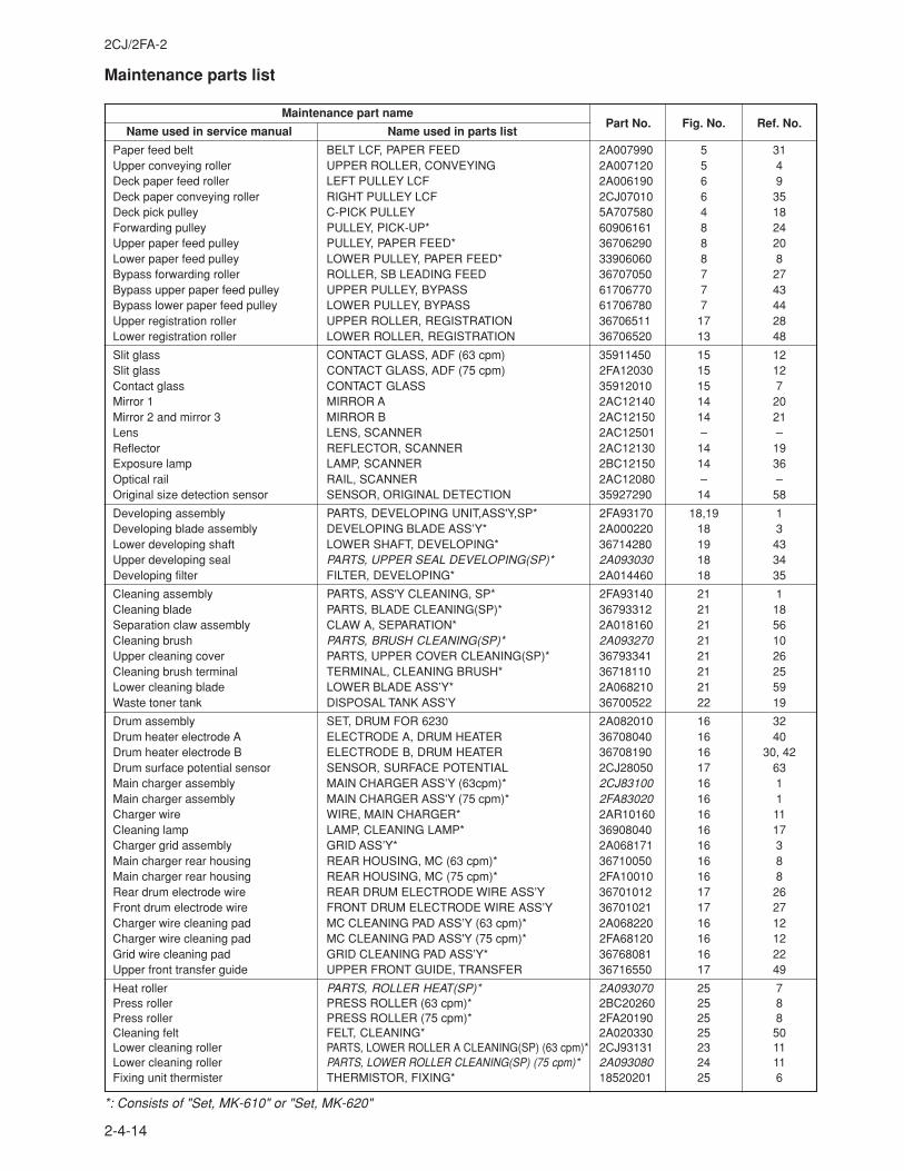
2CJ/2FA-2
2-4-14
Maintenance parts list
Maintenance part namePart No. Fig. No. Ref. No.
Name used in service manual Name used in parts list
Paper feed belt BELT LCF, PAPER FEED 2A007990 5 31Upper conveying roller UPPER ROLLER, CONVEYING 2A007120 5 4Deck paper feed roller LEFT PULLEY LCF 2A006190 6 9Deck paper conveying roller RIGHT PULLEY LCF 2CJ07010 6 35Deck pick pulley C-PICK PULLEY 5A707580 4 18Forwarding pulley PULLEY, PICK-UP* 60906161 8 24Upper paper feed pulley PULLEY, PAPER FEED* 36706290 8 20Lower paper feed pulley LOWER PULLEY, PAPER FEED* 33906060 8 8Bypass forwarding roller ROLLER, SB LEADING FEED 36707050 7 27Bypass upper paper feed pulley UPPER PULLEY, BYPASS 61706770 7 43Bypass lower paper feed pulley LOWER PULLEY, BYPASS 61706780 7 44Upper registration roller UPPER ROLLER, REGISTRATION 36706511 17 28Lower registration roller LOWER ROLLER, REGISTRATION 36706520 13 48
Slit glass CONTACT GLASS, ADF (63 cpm) 35911450 15 12Slit glass CONTACT GLASS, ADF (75 cpm) 2FA12030 15 12Contact glass CONTACT GLASS 35912010 15 7Mirror 1 MIRROR A 2AC12140 14 20Mirror 2 and mirror 3 MIRROR B 2AC12150 14 21Lens LENS, SCANNER 2AC12501 – –Reflector REFLECTOR, SCANNER 2AC12130 14 19Exposure lamp LAMP, SCANNER 2BC12150 14 36Optical rail RAIL, SCANNER 2AC12080 – –Original size detection sensor SENSOR, ORIGINAL DETECTION 35927290 14 58
Developing assembly PARTS, DEVELOPING UNIT,ASS'Y,SP* 2FA93170 18,19 1Developing blade assembly DEVELOPING BLADE ASS’Y* 2A000220 18 3Lower developing shaft LOWER SHAFT, DEVELOPING* 36714280 19 43Upper developing seal PARTS, UPPER SEAL DEVELOPING(SP)* 2A093030 18 34Developing filter FILTER, DEVELOPING* 2A014460 18 35
Cleaning assembly PARTS, ASS'Y CLEANING, SP* 2FA93140 21 1Cleaning blade PARTS, BLADE CLEANING(SP)* 36793312 21 18Separation claw assembly CLAW A, SEPARATION* 2A018160 21 56Cleaning brush PARTS, BRUSH CLEANING(SP)* 2A093270 21 10Upper cleaning cover PARTS, UPPER COVER CLEANING(SP)* 36793341 21 26Cleaning brush terminal TERMINAL, CLEANING BRUSH* 36718110 21 25Lower cleaning blade LOWER BLADE ASS’Y* 2A068210 21 59Waste toner tank DISPOSAL TANK ASS’Y 36700522 22 19
Drum assembly SET, DRUM FOR 6230 2A082010 16 32Drum heater electrode A ELECTRODE A, DRUM HEATER 36708040 16 40Drum heater electrode B ELECTRODE B, DRUM HEATER 36708190 16 30, 42Drum surface potential sensor SENSOR, SURFACE POTENTIAL 2CJ28050 17 63Main charger assembly MAIN CHARGER ASS’Y (63cpm)* 2CJ83100 16 1Main charger assembly MAIN CHARGER ASS'Y (75 cpm)* 2FA83020 16 1Charger wire WIRE, MAIN CHARGER* 2AR10160 16 11Cleaning lamp LAMP, CLEANING LAMP* 36908040 16 17Charger grid assembly GRID ASS’Y* 2A068171 16 3Main charger rear housing REAR HOUSING, MC (63 cpm)* 36710050 16 8Main charger rear housing REAR HOUSING, MC (75 cpm)* 2FA10010 16 8Rear drum electrode wire REAR DRUM ELECTRODE WIRE ASS’Y 36701012 17 26Front drum electrode wire FRONT DRUM ELECTRODE WIRE ASS’Y 36701021 17 27Charger wire cleaning pad MC CLEANING PAD ASS’Y (63 cpm)* 2A068220 16 12Charger wire cleaning pad MC CLEANING PAD ASS'Y (75 cpm)* 2FA68120 16 12Grid wire cleaning pad GRID CLEANING PAD ASS’Y* 36768081 16 22Upper front transfer guide UPPER FRONT GUIDE, TRANSFER 36716550 17 49
Heat roller PARTS, ROLLER HEAT(SP)* 2A093070 25 7Press roller PRESS ROLLER (63 cpm)* 2BC20260 25 8Press roller PRESS ROLLER (75 cpm)* 2FA20190 25 8Cleaning felt FELT, CLEANING* 2A020330 25 50Lower cleaning roller PARTS, LOWER ROLLER A CLEANING(SP) (63 cpm)* 2CJ93131 23 11Lower cleaning roller PARTS, LOWER ROLLER CLEANING(SP) (75 cpm)* 2A093080 24 11Fixing unit thermister THERMISTOR, FIXING* 18520201 25 6
*: Consists of "Set, MK-610" or "Set, MK-620"
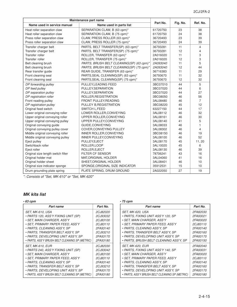
2CJ/2FA-2
2-4-15
Maintenance part namePart No. Fig. No. Ref. No.
Name used in service manual Name used in parts list
Heat roller separation claw SEPARATION CLAW, B (63 cpm)* 61720750 23 38Heat roller separation claw SEPARATION CLAW, B (75 cpm)* 61720750 24 38Press roller separation claw CLAW, PRESS ROLLER (63 cpm)* 36720493 23 39Press roller separation claw CLAW, PRESS ROLLER (75 cpm)* 36720493 24 39
Transfer charger belt PARTS, BELT TRANSFER(SP) (63 cpm)* 36793281 11 4Transfer charger belt PARTS, BELT TRANSFER(SP) (75 cpm)* 36793281 12 4Transfer roller ROLLER, TRANSFER (63 cpm)* 2A016020 11 3Transfer roller ROLLER, TRANSFER (75 cpm)* 2A016020 12 3Belt cleaning brush PARTS, BRUSH BELT CLEANING(SP) (63 cpm)* 2A093040 11 5Belt cleaning brush PARTS, BRUSH BELT CLEANING(SP) (75 cpm)* 2A093040 12 44Rear transfer guide REAR GUIDE, TRANSFER (63 cpm)* 36716383 11 29Front cleaning seal PARTS,SEAL CLEANING(SP) (63 cpm)* 36793670 11 32Front cleaning seal PARTS,SEAL CLEANING(SP) (75 cpm)* 36793670 12 32
DP forwarding pulley PULLEY,LEADING FEED 3BC07010 44 5DP feed pulley PULLEY,SEPARATION 3BC07020 44 6DP separation pulley PULLEY,SEPARATION 3BC07020 44 27DP registration roller ROLLER,REGISTRATION 3BC08050 46 56Front reading pulley FRONT PULLEY,READING 3AL08480 46 7DP registration pulley PULLEY B,REGISTRATION 3BC08220 45 12Original feed switch SWITCH L,FEED 63227150 44 17Lower original conveying roller LOWER ROLLER,CONVEYING 3AL08112 46 32Upper original conveying roller UPPER ROLLER,CONVEYING 3AL08161 46 30Upper original conveying pulley UPPER PULLEY,CONVEYING 3AL08140 41 5Original conveying guide GUIDE,CONVEYING 3AL08033 46 1Original conveying pulley cover COVER,CONVEYING PULLEY 3AL08302 46 4Middle original conveying roller INNER ROLLER,CONVEYING 3BC08150 46 19Middle original conveying pulley INNER PULLEY,CONVEYING 3AL08100 46 52Eject pulley PULLEY,EJECT 3AL08170 45 11, 20Switchback roller ROLLER,LOOP 3AL10020 45 6Eject roller ROLLER,EJECT 3AL08130 46 39Original size length switch filter FILTER CF SENSOR 78706241 43 16Original holder mat MAT,ORIGINAL HOLDER 3AL04060 41 16Original holder sheet SHEET,ORIGINAL HOLDER 3AL08401 46 10Original size indicator sponge SPONGE,ORIGINAL SIZE INDICATOR 35912531 15 10
Drum grounding plate spring PLATE SPRING, DRUM GROUND 2A022050 27 19
MK kits list
• 63 cpm
Part name Part No.
SET, MK-610, USA 2CJ82020• PARTS 120, ASS’Y FIXING UNIT (SP) 2CJ93032• SET, MAIN CHARGER, ASS’Y 2CJ83100• SET, PRIMARY PAPER FEED, ASS’Y 2CJ83110• PARTS, CLEANING ASS’Y, SP 2FA93140• PARTS, TRANSFER BELT ASS’Y, SP 2CJ93210• PARTS, DEVELOPING UNIT ASS’Y, SP 2FA93170• PARTS, ASS’Y BRUSH BELT CLEANING SP (METRIC) 2FA93180
SET, MK-610, EUR 2CJ82030• PARTS 240, ASS’Y FIXING UNIT (SP) 2CJ93042• SET, MAIN CHARGER, ASS’Y 2CJ83100• SET, PRIMARY PAPER FEED, ASS’Y 2CJ83110• PARTS, CLEANING ASS’Y, SP 2FA93140• PARTS, TRANSFER BELT ASS’Y, SP 2CJ93210• PARTS, DEVELOPING UNIT ASS’Y, SP 2FA93170• PARTS, ASS’Y BRUSH BELT CLEANING SP (METRIC) 2FA93180
• 75 cpm
Part name Part No.
SET, MK-620, USA 2FA82030• PARTS, FIXING UNIT ASS’Y 120, SP 2FA93021• SET, MAIN CHARGER, ASS’Y 2FA83020• SET, PRIMARY PAPER FEED, ASS’Y 2CJ83110• PARTS, CLEANING ASS’Y, SP 2FA93140• PARTS, TRANSFER BELT ASS’Y, SP 2FA93160• PARTS, DEVELOPING UNIT ASS’Y, SP 2FA93170• PARTS, BRUSH BELT CLEANING ASS’Y, SP 2FA93150
SET, MK-620, EUR 2FA82040• PARTS, FIXING UNIT ASS’Y 140, SP 2FA93031• SET, MAIN CHARGER, ASS’Y 2FA83020• SET, PRIMARY PAPER FEED, ASS’Y 2CJ83110• PARTS, CLEANING ASS’Y, SP 2FA93140• PARTS, TRANSFER BELT ASS’Y, SP 2FA93160• PARTS, DEVELOPING UNIT ASS’Y, SP 2FA93170• PARTS, ASS’Y BRUSH BELT CLEANING SP (METRIC) 2FA93180
*: Consists of "Set, MK-610" or "Set, MK-620"
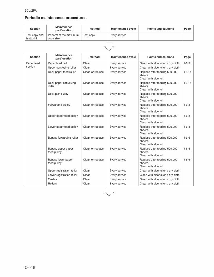
2CJ/2FA
2-4-16
Periodic maintenance procedures
MaintenanceSection part/location Method Maintenance cycle Points and cautions Page
Test copy and Perform at the maximum Test copy Every servicetest print copy size
MaintenanceSection part/location Method Maintenance cycle Points and cautions Page
Paper feed Paper feed belt Clean Every service Clean with alcohol or a dry cloth. 1-6-9section Upper conveying roller Clean Every service Clean with alcohol or a dry cloth.
Deck paper feed roller Clean or replace Every service Replace after feeding 500,000 1-6-11sheets.Clean with alcohol.
Deck paper conveying Clean or replace Every service Replace after feeding 500,000 1-6-11roller sheets.
Clean with alcohol.
Deck pick pulley Clean or replace Every service Replace after feeding 500,000sheets.Clean with alcohol.
Forwarding pulley Clean or replace Every service Replace after feeding 500,000 1-6-3sheets.Clean with alcohol.
Upper paper feed pulley Clean or replace Every service Replace after feeding 500,000 1-6-3sheets.Clean with alcohol.
Lower paper feed pulley Clean or replace Every service Replace after feeding 500,000 1-6-3sheets.Clean with alcohol.
Bypass forwarding roller Clean or replace Every service Replace after feeding 500,000 1-6-6sheets.Clean with alcohol.
Bypass upper paper Clean or replace Every service Replace after feeding 500,000 1-6-6feed pulley sheets.
Clean with alcohol.
Bypass lower paper Clean or replace Every service Replace after feeding 500,000 1-6-6feed pulley sheets.
Clean with alcohol.
Upper registration roller Clean Every service Clean with alcohol or a dry cloth.
Lower registration roller Clean Every service Clean with alcohol or a dry cloth.
Guides Clean Every service Clean with alcohol or a dry cloth.
Rollers Clean Every service Clean with alcohol or a dry cloth.
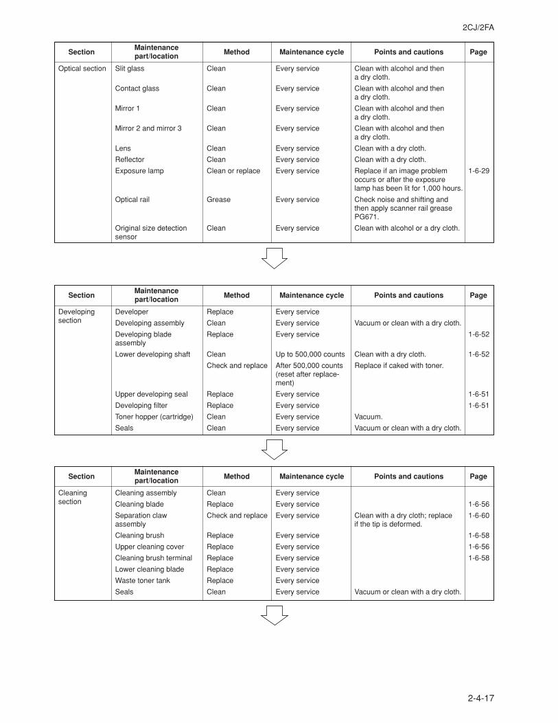
2CJ/2FA
2-4-17
MaintenanceSection part/location Method Maintenance cycle Points and cautions Page
Optical section Slit glass Clean Every service Clean with alcohol and thena dry cloth.
Contact glass Clean Every service Clean with alcohol and thena dry cloth.
Mirror 1 Clean Every service Clean with alcohol and thena dry cloth.
Mirror 2 and mirror 3 Clean Every service Clean with alcohol and thena dry cloth.
Lens Clean Every service Clean with a dry cloth.
Reflector Clean Every service Clean with a dry cloth.
Exposure lamp Clean or replace Every service Replace if an image problem 1-6-29occurs or after the exposurelamp has been lit for 1,000 hours.
Optical rail Grease Every service Check noise and shifting andthen apply scanner rail greasePG671.
Original size detection Clean Every service Clean with alcohol or a dry cloth.sensor
MaintenanceSection part/location Method Maintenance cycle Points and cautions Page
Developing Developer Replace Every servicesection Developing assembly Clean Every service Vacuum or clean with a dry cloth.
Developing blade Replace Every service 1-6-52assembly
Lower developing shaft Clean Up to 500,000 counts Clean with a dry cloth. 1-6-52
Check and replace After 500,000 counts Replace if caked with toner.(reset after replace-ment)
Upper developing seal Replace Every service 1-6-51
Developing filter Replace Every service 1-6-51
Toner hopper (cartridge) Clean Every service Vacuum.
Seals Clean Every service Vacuum or clean with a dry cloth.
MaintenanceSection part/location Method Maintenance cycle Points and cautions Page
Cleaning Cleaning assembly Clean Every servicesection Cleaning blade Replace Every service 1-6-56
Separation claw Check and replace Every service Clean with a dry cloth; replace 1-6-60assembly if the tip is deformed.
Cleaning brush Replace Every service 1-6-58
Upper cleaning cover Replace Every service 1-6-56
Cleaning brush terminal Replace Every service 1-6-58
Lower cleaning blade Replace Every service
Waste toner tank Replace Every service
Seals Clean Every service Vacuum or clean with a dry cloth.
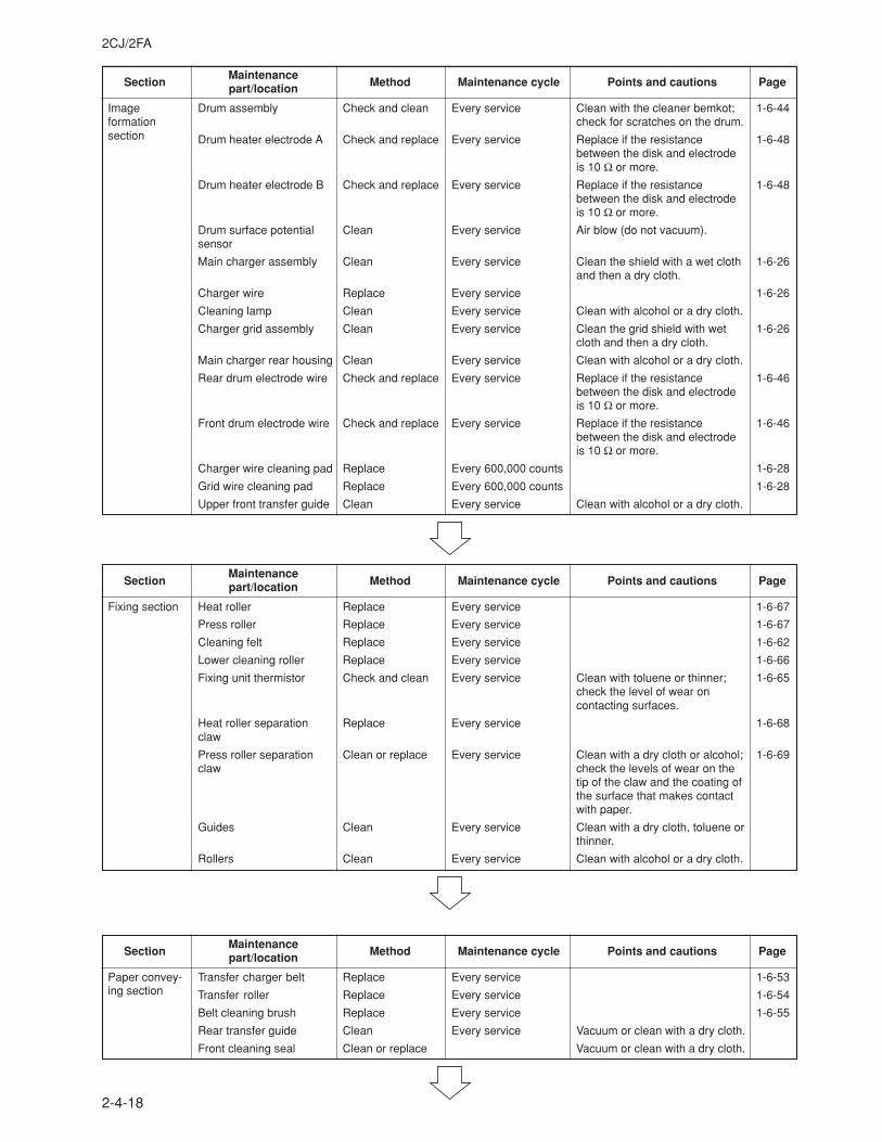
2CJ/2FA
2-4-18
MaintenanceSection part/location Method Maintenance cycle Points and cautions Page
Image Drum assembly Check and clean Every service Clean with the cleaner bemkot; 1-6-44formation check for scratches on the drum.section Drum heater electrode A Check and replace Every service Replace if the resistance 1-6-48
between the disk and electrodeis 10 Ω or more.
Drum heater electrode B Check and replace Every service Replace if the resistance 1-6-48between the disk and electrodeis 10 Ω or more.
Drum surface potential Clean Every service Air blow (do not vacuum).sensor
Main charger assembly Clean Every service Clean the shield with a wet cloth 1-6-26and then a dry cloth.
Charger wire Replace Every service 1-6-26
Cleaning lamp Clean Every service Clean with alcohol or a dry cloth.
Charger grid assembly Clean Every service Clean the grid shield with wet 1-6-26cloth and then a dry cloth.
Main charger rear housing Clean Every service Clean with alcohol or a dry cloth.
Rear drum electrode wire Check and replace Every service Replace if the resistance 1-6-46between the disk and electrodeis 10 Ω or more.
Front drum electrode wire Check and replace Every service Replace if the resistance 1-6-46between the disk and electrodeis 10 Ω or more.
Charger wire cleaning pad Replace Every 600,000 counts 1-6-28
Grid wire cleaning pad Replace Every 600,000 counts 1-6-28
Upper front transfer guide Clean Every service Clean with alcohol or a dry cloth.
MaintenanceSection part/location Method Maintenance cycle Points and cautions Page
Fixing section Heat roller Replace Every service 1-6-67
Press roller Replace Every service 1-6-67
Cleaning felt Replace Every service 1-6-62
Lower cleaning roller Replace Every service 1-6-66
Fixing unit thermistor Check and clean Every service Clean with toluene or thinner; 1-6-65check the level of wear oncontacting surfaces.
Heat roller separation Replace Every service 1-6-68claw
Press roller separation Clean or replace Every service Clean with a dry cloth or alcohol; 1-6-69claw check the levels of wear on the
tip of the claw and the coating ofthe surface that makes contactwith paper.
Guides Clean Every service Clean with a dry cloth, toluene orthinner.
Rollers Clean Every service Clean with alcohol or a dry cloth.
MaintenanceSection part/location Method Maintenance cycle Points and cautions Page
Paper convey- Transfer charger belt Replace Every service 1-6-53ing section Transfer roller Replace Every service 1-6-54
Belt cleaning brush Replace Every service 1-6-55
Rear transfer guide Clean Every service Vacuum or clean with a dry cloth.
Front cleaning seal Clean or replace Vacuum or clean with a dry cloth.
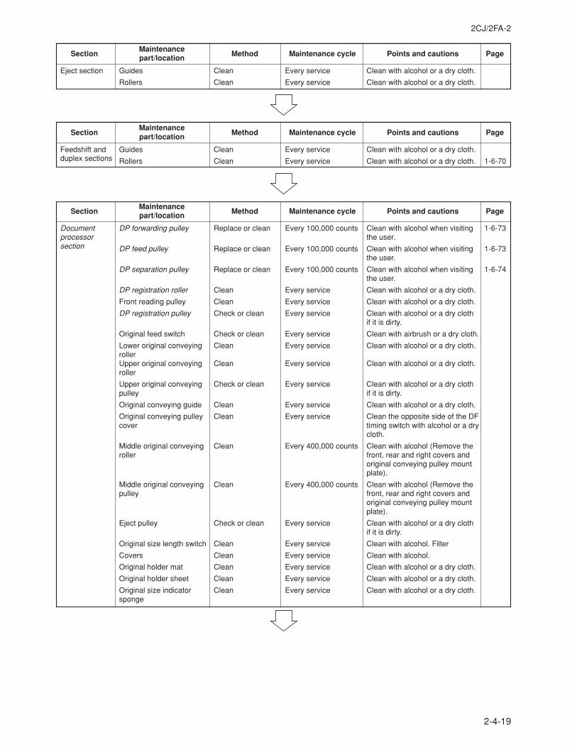
2CJ/2FA-2
2-4-19
MaintenanceSection part/location Method Maintenance cycle Points and cautions Page
Eject section Guides Clean Every service Clean with alcohol or a dry cloth.
Rollers Clean Every service Clean with alcohol or a dry cloth.
MaintenanceSection part/location Method Maintenance cycle Points and cautions Page
Feedshift and Guides Clean Every service Clean with alcohol or a dry cloth.duplex sections Rollers Clean Every service Clean with alcohol or a dry cloth. 1-6-70
MaintenanceSection part/location Method Maintenance cycle Points and cautions Page
Document DP forwarding pulley Replace or clean Every 100,000 counts Clean with alcohol when visiting 1-6-73processor the user.section DP feed pulley Replace or clean Every 100,000 counts Clean with alcohol when visiting 1-6-73
the user.
DP separation pulley Replace or clean Every 100,000 counts Clean with alcohol when visiting 1-6-74the user.
DP registration roller Clean Every service Clean with alcohol or a dry cloth.
Front reading pulley Clean Every service Clean with alcohol or a dry cloth.
DP registration pulley Check or clean Every service Clean with alcohol or a dry clothif it is dirty.
Original feed switch Check or clean Every service Clean with airbrush or a dry cloth.
Lower original conveying Clean Every service Clean with alcohol or a dry cloth.rollerUpper original conveying Clean Every service Clean with alcohol or a dry cloth.roller
Upper original conveying Check or clean Every service Clean with alcohol or a dry clothpulley if it is dirty.
Original conveying guide Clean Every service Clean with alcohol or a dry cloth.
Original conveying pulley Clean Every service Clean the opposite side of the DFcover timing switch with alcohol or a dry
cloth.
Middle original conveying Clean Every 400,000 counts Clean with alcohol (Remove theroller front, rear and right covers and
original conveying pulley mountplate).
Middle original conveying Clean Every 400,000 counts Clean with alcohol (Remove thepulley front, rear and right covers and
original conveying pulley mountplate).
Eject pulley Check or clean Every service Clean with alcohol or a dry clothif it is dirty.
Original size length switch Clean Every service Clean with alcohol. Filter
Covers Clean Every service Clean with alcohol.
Original holder mat Clean Every service Clean with alcohol or a dry cloth.
Original holder sheet Clean Every service Clean with alcohol or a dry cloth.
Original size indicator Clean Every service Clean with alcohol or a dry cloth.sponge
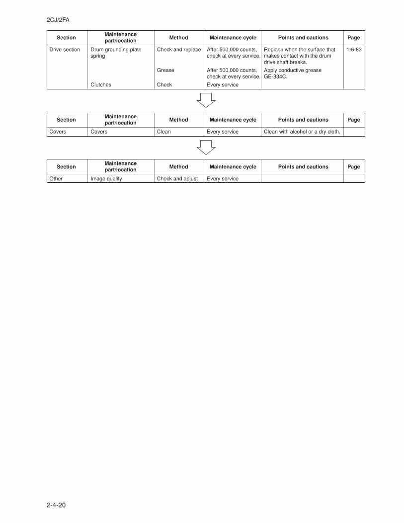
2CJ/2FA
2-4-20
MaintenanceSection part/location Method Maintenance cycle Points and cautions Page
Drive section Drum grounding plate Check and replace After 500,000 counts, Replace when the surface that 1-6-83spring check at every service. makes contact with the drum
drive shaft breaks.
Grease After 500,000 counts, Apply conductive greasecheck at every service. GE-334C.
Clutches Check Every service
MaintenanceSection part/location Method Maintenance cycle Points and cautions Page
Covers Covers Clean Every service Clean with alcohol or a dry cloth.
MaintenanceSection part/location Method Maintenance cycle Points and cautions Page
Other Image quality Check and adjust Every service
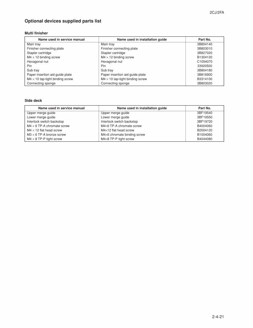
2CJ/2FA
2-4-21
Optional devices supplied parts list
Multi finisher
Name used in service manual Name used in installation guide Part No.Main tray Main tray 3B804140Finisher connecting plate Finisher connecting plate 3B803010Stapler cartridge Stapler cartridge 3B827020M4 × 12 binding screw M4 × 12 binding screw B1304120Hexagonal nut Hexagonal nut C1054070Pin Pin 33920500Sub tray Sub tray 3B804180Paper insertion aid guide plate Paper insertion aid guide plate 3B816900M4 × 10 tap-tight binding screw M4 × 10 tap-tight binding screw B3314100Connecting sponge Connecting sponge 3B803020
Name used in service manual Name used in installation guide Part No.Upper merge guide Upper merge guide 3BF19540Lower merge guide Lower merge guide 3BF19550Interlock switch backstop Interlock switch backstop 3BF19720M4 × 6 TP-A chromate screw M4×6 TP-A chromate screw B4004060M4 × 12 flat head screw M4×12 flat head screw B2004120M3 × 6 TP-A bronze screw M4×6 chromate binding screw B1004060M4 × 8 TP-P tight screw M4×8 TP-P tight screw B4044080
Side deck
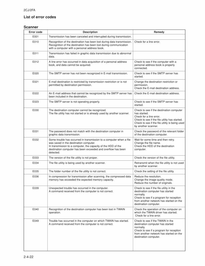
2CJ/2FA
2-4-22
List of error codes
ScannerError code Description Remedy
Transmission has been canceled and interrupted during transmission.
Recognition of the destination has been lost during data transmission.Recognition of the destination has been lost during communicationwith a computer with a personal address book.
Transmission has failed in graphic data transmission due to abnormaldata.
A line error has occurred in data acquisition of a personal addressbook, and data cannot be acquired.
The SMTP server has not been recognized in E-mail transmission.
E-mail destination is restricted by transmission restriction or is notpermitted by destination permission.
An E-mail address that cannot be recognized by the SMTP server hasbeen included in the destination.
The SMTP server is not operating properly.
The destination computer cannot be recognized.The file utility has not started or is already used by another scanner.
The password does not match with the destination computer ingraphic data transmission.
Some trouble has occurred in transmission to a computer when a filewas saved in the destination computer.In transmission to a computer, the capacity of the HDD of thedestination computer has been exceeded and overflow has beendetected.
The version of the file utility is not proper.
The file utility is being used by another scanner.
The folder number of the file utility is not correct.
In compression for transmission after scanning, the compressed datamemory has exceeded the expected memory capacity.
Unexpected trouble has occurred in the computer.A command received from the computer is not correct.
Recognition of the destination computer has been lost in TWAINoperation.
Trouble has occurred in the computer on which TWAIN has started.A command received from the computer is not correct.
Check for a line error.
Check to see if the computer with apersonal address book is properlyconnected.
Check to see if the SMTP server hasstarted.
Change the destination restriction orpermission.Check the E-mail destination address.
Check the E-mail destination address.
Check to see if the SMTP server hasstarted.
Check to see if the destination computerhas started.Check for a line error.Check to see if the file utility has started.Check to see if the file utility is being usedby another scanner.
Check the password of the relevant folderof the destination computer.
Wait for some time and then retry.Change the file name.Check the HDD of the destinationcomputer.
Check the version of the file utility.
Retransmit when the file utility is not usedby another scanner.
Check the setting of the file utility.
Reduce the resolution.Change the image quality mode.Reduce the number of originals.
Check to see if the file utility in thedestination computer has startednormally.Check to see if a program for receptionfrom another network has started on thedestination computer.
Check the operation of the computer onwhich the TWAIN driver has started. Check for a line error.
Check to see if the TWAIN in thedestination computer has startednormally.Check to see if a program for receptionfrom another network has started on thedestination computer.
E001
E010
E011
E012
E020
E021
E022
E023
E030
E031
E032
E033
E034
E035
E036
E039
E040
E049
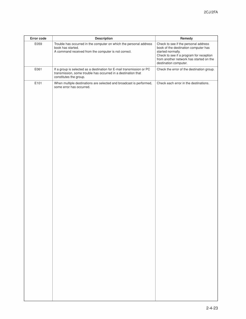
2CJ/2FA
2-4-23
Error code Description Remedy
E059
E061
E101
Trouble has occurred in the computer on which the personal addressbook has started.A command received from the computer is not correct.
If a group is selected as a destination for E-mail transmission or PCtransmission, some trouble has occurred in a destination thatconstitutes the group.
When multiple destinations are selected and broadcast is performed,some error has occurred.
Check to see if the personal addressbook of the destination computer hasstarted normally.Check to see if a program for receptionfrom another network has started on thedestination computer.
Check the error of the destination group.
Check each error in the destinations.
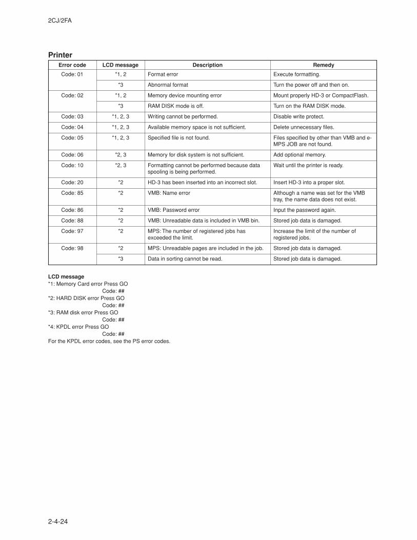
2CJ/2FA
2-4-24
PrinterError code LCD message Description Remedy
Format error
Abnormal format
Memory device mounting error
RAM DISK mode is off.
Writing cannot be performed.
Available memory space is not sufficient.
Specified file is not found.
Memory for disk system is not sufficient.
Formatting cannot be performed because dataspooling is being performed.
HD-3 has been inserted into an incorrect slot.
VMB: Name error
VMB: Password error
VMB: Unreadable data is included in VMB bin.
MPS: The number of registered jobs hasexceeded the limit.
MPS: Unreadable pages are included in the job.
Data in sorting cannot be read.
Execute formatting.
Turn the power off and then on.
Mount properly HD-3 or CompactFlash.
Turn on the RAM DISK mode.
Disable write protect.
Delete unnecessary files.
Files specified by other than VMB and e-MPS JOB are not found.
Add optional memory.
Wait until the printer is ready.
Insert HD-3 into a proper slot.
Although a name was set for the VMBtray, the name data does not exist.
Input the password again.
Stored job data is damaged.
Increase the limit of the number ofregistered jobs.
Stored job data is damaged.
Stored job data is damaged.
Code: 01
Code: 02
Code: 03
Code: 04
Code: 05
Code: 06
Code: 10
Code: 20
Code: 85
Code: 86
Code: 88
Code: 97
Code: 98
*1, 2
*3
*1, 2
*3
*1, 2, 3
*1, 2, 3
*1, 2, 3
*2, 3
*2, 3
*2
*2
*2
*2
*2
*2
*3
LCD message*1: Memory Card error Press GO
Code: ##*2: HARD DISK error Press GO
Code: ##*3: RAM disk error Press GO
Code: ##*4: KPDL error Press GO
Code: ##For the KPDL error codes, see the PS error codes.
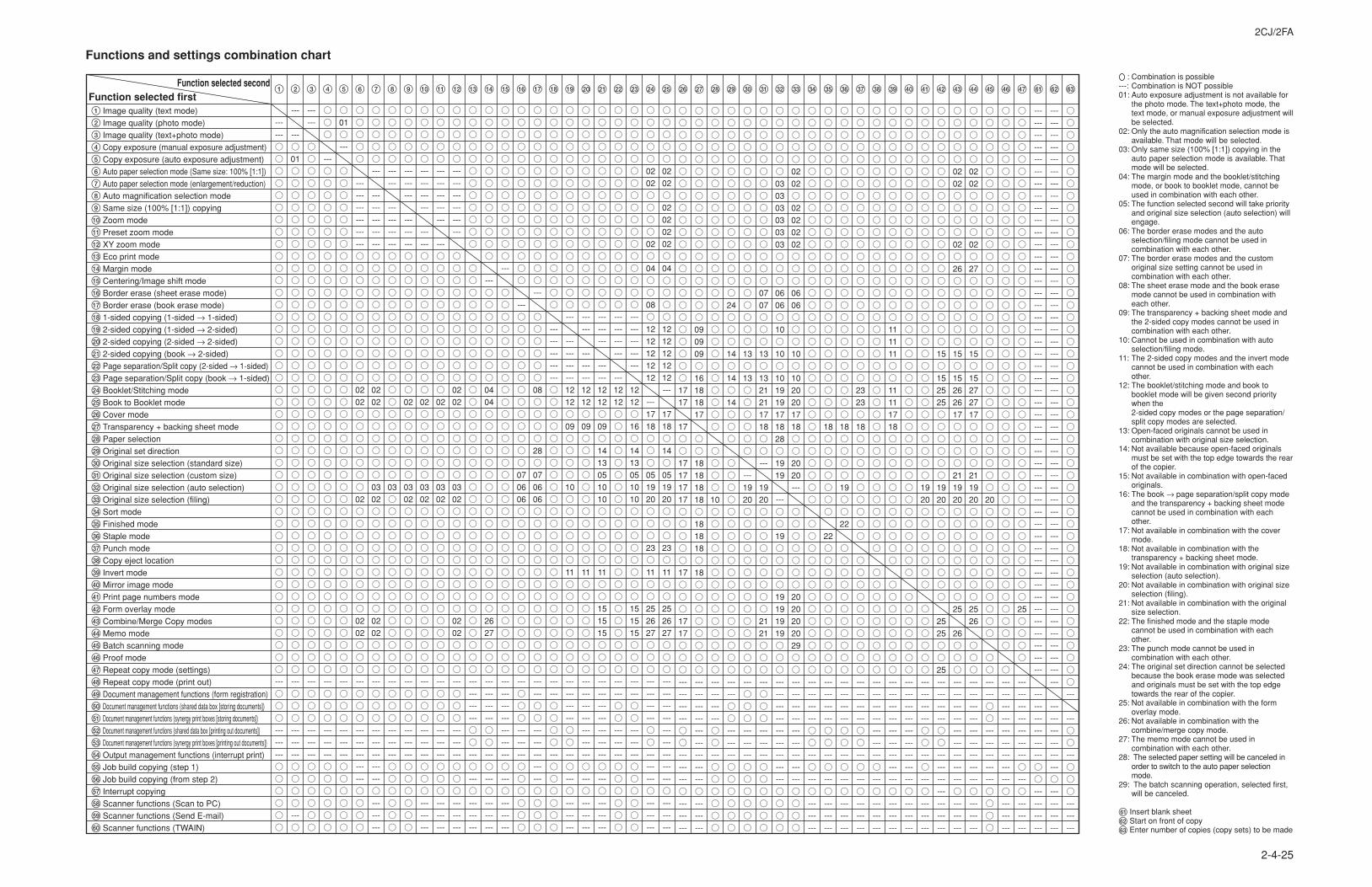
2CJ/2FA
2-4-25
Functions and settings combination chart
02
02
02
02
02
02
04
12
12
12
12
12
17
18
14
05
19
20
23
11
25
26
27
02
02
02
04
08
12
12
12
12
12
17
18
05
19
20
23
11
25
26
27
12
12
16
14
13
05
10
10
15
15
15
02
02
03
02
02
02
03
02
03
02
02
03
02
02
03
02
02
02
03
02
02
02
04
04
26
27
07
06
06
08
28
07
06
06
12
12
09
10
11
12
12
09
11
12
12
09
14
13
05
10
10
11
15
15
15
12
12
02
02
02
02
02
01
01
Image quality (text mode)
Image quality (photo mode)
Image quality (text+photo mode)
Copy exposure (manual exposure adjustment)
Copy exposure (auto exposure adjustment)
Auto paper selection mode (Same size: 100% [1:1])
Auto paper selection mode (enlargement/reduction)
Auto magnification selection mode
Same size (100% [1:1]) copying
Zoom mode
Preset zoom mode
XY zoom mode
Eco print mode
Margin mode
Centering/Image shift mode
Border erase (sheet erase mode)
Border erase (book erase mode)
1-sided copying (1-sided → 1-sided)
2-sided copying (1-sided → 2-sided)
2-sided copying (2-sided → 2-sided)
2-sided copying (book → 2-sided)
Page separation/Split copy (2-sided → 1-sided)
Page separation/Split copy (book → 1-sided)
Booklet/Stitching mode
Book to Booklet mode
Cover mode
Transparency + backing sheet mode
Paper selection
Original set direction
Original size selection (standard size)
Original size selection (custom size)
Original size selection (auto selection)
Original size selection (filing)
Sort mode
Finished mode
Staple mode
Punch mode
Copy eject location
Invert mode
Mirror image mode
Print page numbers mode
Form overlay mode
Combine/Merge Copy modes
Memo mode
Batch scanning mode
Proof mode
Repeat copy mode (settings)
Repeat copy mode (print out)
Document management functions (form registration)
Document management functions (shared data box [storing documents])
Document management functions (synergy print boxes [storing documents])
Document management functions (shared data box [printing out documents])
Document management functions (synergy print boxes [printing out documents])
Output management functions (interrupt print)
Job build copying (step 1)
Job build copying (from step 2)
Interrupt copying
Scanner functions (Scan to PC)
Scanner functions (Send E-mail)
Scanner functions (TWAIN)
Function selected secondFunction selected first
17
17
17
17
17
17
17
17
17
17
09
09
09
16
18
18
17
18
18
18
18
18
18
18
18
10
24
14
14
14
13
13
19
20
07
07
13
13
21
21
17
18
19
20
21
21
03
03
03
03
03
03
06
06
10
10
10
19
19
17
18
28
19
19
19
19
19
19
19
02
02
02
02
02
02
06
06
10
10
20
20
17
18
20
20
20
20
20
20
29
18
22
18
19
22
23
23
18
11
11
11
11
11
17
18
19
20
15
15
25
25
19
20
25
25
25
02
02
02
26
15
15
26
26
17
21
19
20
25
26
02
02
02
27
15
15
27
27
17
21
19
20
25
26
20
25
: Combination is possible---: Combination is NOT possible01: Auto exposure adjustment is not available for
the photo mode. The text+photo mode, thetext mode, or manual exposure adjustment willbe selected.
02: Only the auto magnification selection mode isavailable. That mode will be selected.
03: Only same size (100% [1:1]) copying in theauto paper selection mode is available. Thatmode will be selected.
04: The margin mode and the booklet/stitchingmode, or book to booklet mode, cannot beused in combination with each other.
05: The function selected second will take priorityand original size selection (auto selection) willengage.
06: The border erase modes and the autoselection/filing mode cannot be used incombination with each other.
07: The border erase modes and the customoriginal size setting cannot be used incombination with each other.
08: The sheet erase mode and the book erasemode cannot be used in combination witheach other.
09: The transparency + backing sheet mode andthe 2-sided copy modes cannot be used incombination with each other.
10: Cannot be used in combination with autoselection/filing mode.
11: The 2-sided copy modes and the invert modecannot be used in combination with eachother.
12: The booklet/stitching mode and book tobooklet mode will be given second prioritywhen the2-sided copy modes or the page separation/split copy modes are selected.
13: Open-faced originals cannot be used incombination with original size selection.
14: Not available because open-faced originalsmust be set with the top edge towards the rearof the copier.
15: Not available in combination with open-facedoriginals.
16: The book → page separation/split copy modeand the transparency + backing sheet modecannot be used in combination with eachother.
17: Not available in combination with the covermode.
18: Not available in combination with thetransparency + backing sheet mode.
19: Not available in combination with original sizeselection (auto selection).
20: Not available in combination with original sizeselection (filing).
21: Not available in combination with the originalsize selection.
22: The finished mode and the staple modecannot be used in combination with eachother.
23: The punch mode cannot be used incombination with each other.
24: The original set direction cannot be selectedbecause the book erase mode was selectedand originals must be set with the top edgetowards the rear of the copier.
25: Not available in combination with the formoverlay mode.
26: Not available in combination with thecombine/merge copy mode.
27: The memo mode cannot be used incombination with each other.
28: The selected paper setting will be canceled inorder to switch to the auto paper selectionmode.
29: The batch scanning operation, selected first,will be canceled.
¡ Insert blank sheet™ Start on front of copy£ Enter number of copies (copy sets) to be made
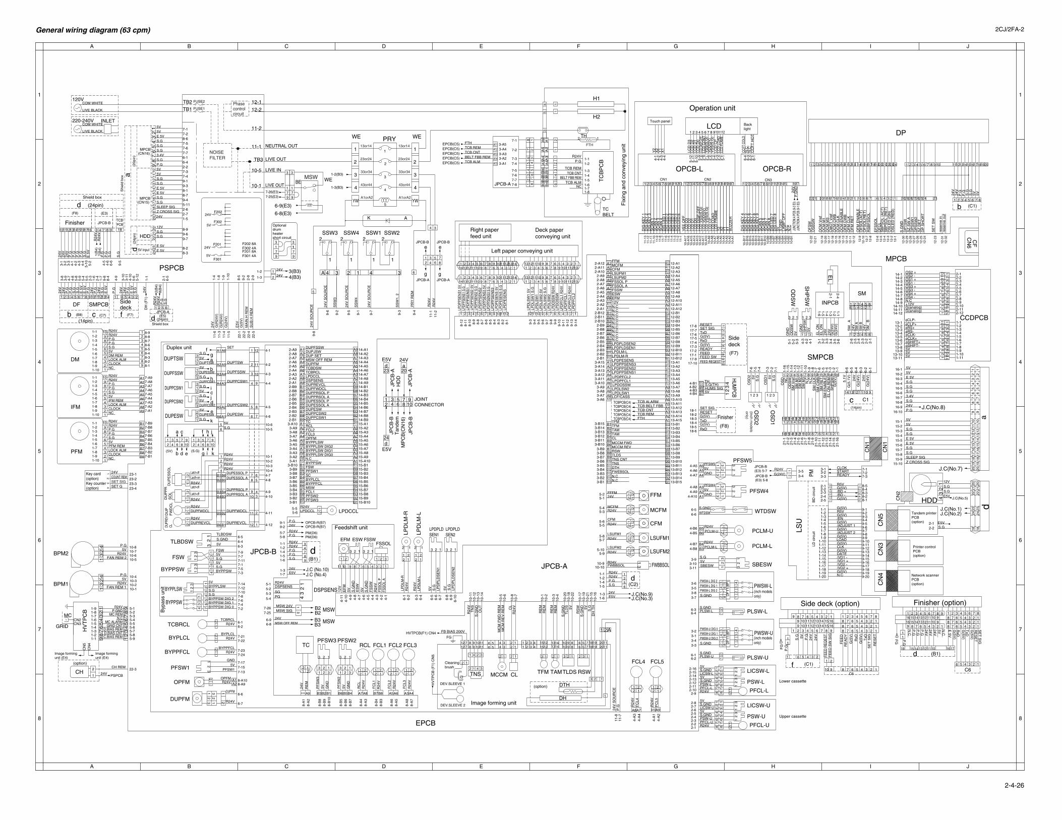
A B C D E F G H I J
A B C D E F G H I J
1
2
3
4
5
6
7
8
1
2
3
4
5
6
7
8
General wiring diagram (63 cpm) 2CJ/2FA-2
2-4-26
13or14
43or44
23or24
33or34
A1orA2
13or14
43or44
23or24
33or34
A1orA2YW YW
4
5
3
2
1
AK
WE WE
Phasecontrolcircuit
11-2
12-2
12-1FUSE2
FUSE1TB1
TB2
aS
hiel
d bo
x
(CN16)MPCB
(CN15)MPCB
NOISEFILTER
WEBE
7-25(E3)7-26(E3)
6-8(E3)
6-9(E3)
Optionaldrumheatershort circuit
5V
5V
24V
24VF201 8A F301 4A
F202 8A F302 4A
1-3(B3)
1-2(B3)
EPCB(C5)EPCB(C5)EPCB(C5)EPCB(C5)EPCB(C5)
P.G
P.G
P.G
24V
24V
S.G
7-47-2
7-1
7-3
FSW
S.G5V
5VS.GBYPPSW
5VBYPPLSWS.GS.G
3 13
26
54
21
32
1
76
54
32
132
1
Byp
ass
unit
7-67-87-107-127-14
7-5
7-117-77-9
BYPPSW DIG 2
BYPPSW DIG 0BYPPSW DIG 1
12
34
4-B3
5-4
4-B4
4-B14-B2
43
2
S.G(TH)
1
TH
HUMS SIG5V
WTDSWS.GND
RE
M24
V
PGSG
DSPSENSR24V
5-25-3
5-1
1
2
Finisher
P.G
24V
S.G
DF SMPCB
b
S.G
S.G
P.G
P.G
24V
24V
98
76
54
32
1
Printer controlPCB(option)
7-37-27-1
8-58-48-38-28-1
PM
LD c
ircui
tB
D c
ircui
t
3-5READYSTARTCLOK
3-23-1
3-4 3-3
G(5V)/BD -/BD +G(5V)R5V
2-32-22-1
2-42-5
1-131-121-111-101-9
1-31-21-1
1-41-5
1-8
1-61-7LS
U
HDD
2-12-22-32-42-52-62-7
1-11-21-31-41-51-61-71-81-91-101-11
CCDPCB
1 2 3
1 2 3 4 5 6
1-4
G(5
V)
(Inch models
only)
1-6
1-3
3-4
3-5
3-6
1-21-1
3-1
6-4
6-3
6-2
6-1
G(2
4V)
24V
SMPCB
21-1
521
-16
5-1
5-2
5-3
5VOD
SW
GN
DO
DS
WS
M V
ref
SM
M1
1-13
1-14
4-3
4-2
4-1
GN
DS
HP
SW
5VS
M M
3N
.C
SM
CLK
SM
CW
BS
M R
ET
SM
EN
AB
LEE
L O
N R
EM
SH
PS
W
1 2 3
3-2
3-3
24V
G(2
4V)
G(2
4V)
EL
ON
EL
ON
24V
1-51-4
2-1
2-2
2-3
2-4
2-5
2-6
SM
_ B
24V
SM
BS
M A
24V
SM
_ A
1-12
1-11
1-10
1-9
1-8
1-7
1-6
1-5
1-3
1-2
1-1
SM
M2
2-1
2-4
INPCB
SM
EL
DUPESW
DUPTSW
DUPPCSW1
SET
S.G
S.G
5V
5VDUPESW
5VS.G
DUPTSW
DUPESSW
DUPPCSW1S.G5V
FFM
MCFM
CFM
LSUFM1
LSUFM2
FWBBSOL
21
34
62
5
1
(20p
in)
A
A 4 3 4 32 1
4
3
2
1
4
3
2
1
9-8
9-3
9-5
4-5
4-6
6-6
5-2
4-2
4-3
5-104-4
4-1
3-3
3-2
3-1
6-5
2-1
1-1
5-12
3-10
3-11
4-10
5-6
4-9
8-4
2-3
1-6
2-4
1-7
5-8
5-9
5-5
5-4
4-7
4-8
3-9
3-8
2-9
2-8
9-2
8-5
1-9
1-10
1-8
1-4
24V1-5
8-38-2
8-99-69-7
2-7
9-45-112-6
9-38-18-7
9-17-47-3
6-16-42-2
7-57-67-7
8-67-27-1
J.C (No.4)J.C (No.10)
J.C(No.3)J.C(No.9)
J.C(No.5)
J.C(No.2)J.C(No.1)
J.C(No.7)
J.C(No.8)M
PC
B(C
N16
)T
ande
mH
DD
JPC
B-B
JPC
B-B
JPC
B-A
JPC
B-A
24V
E5V
E5V
20a
d24
d23
JOINT CONNECTOR
9108
76453
21
11
Shield box
Shield box
d98743
d6521
1716
11
19 15 14 13 1211 10
2020
d99
1818
E5V
(24p
in)
d 5V input
2423
E 5VE 5V
P.G
P.G
S.G
S.G
181917
65
43
21
(24pin)
(24pin)d
P.GR24V
TCB ALMBELT FBB REM
TCB CNTTCB REM
MSW
MSW
N.C
JPCB-B (E3) 5-8
JPCB-B (E3) 5-7
1516 1413121110 9 8 7 6 5 4 3 2 11 2 3 4 5 6 7 8 910111213141516
16151413121110987654321
JPCB-B JPCB-B
JPCB-A JPCB-A
910 8 7 6 5 4 3 2 1
9-149-159-169-179-189-199-20
9-139-129-119-109-9
9-39-29-1
9-49-5
9-8
9-69-7
DATE
CLK
LOAD
N.CG(5V)
G(5V)
G(5V)
G(5V)
G(5V)
G(5V)
G(5V)
G(5V)
/VD2 -/VD2 +
/VD1 -/VD1 +
/EN
/ADJUST 2
/ADJUST 1
R5V
HV
TP
CB
(F
1) C
N5 (B1)
(C1)
1 6 5 4 3 2
TCBPCB(C4)TCBPCB(C4)TCBPCB(C4)TCBPCB(C4)
87654321
JUNC
TION
A PC
B (9-
1 E3)
JUNC
TION
A PC
B (9-
2 E3)
(C1)
(E3)(F8)
(E5)(F7)(B8) (C7)
C1
12345678910111213
12345678910111213
13121110987654321
131211109876543211234567891011121314
1234567891011121314
1413121110987654321
1413121110987654321
e e
gg
(C2)
R24V
JPCB-A
S.G
P.G
8(B
4)2(
B4)
R24
VR
24V
(B1)
24V5V
7(B
4)1(
B4)
R24
VR
24V
JPCB-B
15 1614131211
TCBPCB
HDD S.GS.G12V
E 5V
S.G3.4VS.GS.GS.G
5V5V
E 5VE 5V
S.GS.G
S.GS.G5V
P.G5V
Z CROSS SIGSLEEP SIG
HVTPCB(F1) CN4
Image formingunit (E4)
Image formingunit (E4)
10-510-6
10-410-310-210-1
4(B3)3(B3)
B3B3B2B2
30292827262524 232221 20191817161514131211 10 9 8 7 6 5 4 3 2 1
(F8)
C6
(F7)
TCBPCB(C4)
PM(D6)
OPCB-R(B7)
87
6453
21
2122
2324
2019
1817
1615
1413
1211
106
78
2122
2324
2019
1817
1615
1413
1211
106
78
CN
2
S.GS.G
S.GS.G
S.GS.G
E 5V
E 5VE 5V
5V
5V5V
15-5
S.G
12-3
2re
serv
e ou
tre
serv
e in
12-3
1
242322212019181716151413121110987654321 10
5V
201918171615141312
S.G
ND
12-3
0
12-2
112
-22
12-2
3
12-2
412
-25
12-2
612
-27
12-2
812
-29
12-1
12-2
12-3
12-4
12-5
12-6
12-8
12-7
12-1
012
-9
12-1
212
-11
12-1
412
-13
12-1
612
-15
12-1
812
-17
12-2
012
-19
DP
TS
WS
Z S
W A
DP
SS
W1
SE
T S
W
DP
SS
W2
SZ
DE
TD
P S
HO
RT
OF
SW
OS
BS
W
119874 65321
b
S.G
5VP.G
P.G24V
24V
RS
BF
SS
OL
OF
SO
L(R
ET
)O
FS
OL(
AC
T)
OF
M C
LKO
FM
CW
BO
CM
EN
AB
LEO
CM
CLK
OC
M C
WB
CM
OT
Vre
fO
CM
M3
DP
OS
LED
(R
ED
)O
SLE
D (
GN
)S
BP
SO
L (R
ET
)S
BP
SO
L (A
CT
)O
FC
LE
FS
SO
L
OF
M E
NA
BLE
OF
M R
ET
OC
M M
1O
CM
Vre
f
10-1010-9
5-105-9
5-85-7
5-65-5
5-45-3
5-25-1
123456789101112
9-13
9-149-4
9-5
9-6
9-7
9-8
9-9
9-10
9-11
9-12
121110987654321
4-1
4-2
4-3
4-4
4-5
4-6
4-7
4-8
4-9
4-10
4-11
2 11 2
122 1
E5V
S.GP.G
24V
R24V
1-6
1-51-4
1-3
1-21-1
3-B103-B113-B123-B133-B143-B15
A14A13A12A11
A10A9A8A7A6A5A4A3A2
A15
A1
B15B14B13B12B11B10B9B8B7B6B5B4B3B2B1
B13B14B15
B12B11B10B9B8B7B6B5B4B3B2B1
A13A14A15
A1A2A3A4A5A6A7A8A9A10A11A12
B12B11B10B9B8B7B6B5B4B3B2B1
A1A2A3A4A5A6A7A8A9A10A11A12
B10B11B12
B1B2B3B4B5B6B7B8B9
A10A11A12
A1A2A3A4A5A6A7A8A9
PM(D6)
OPCB-R(B7)
P.G5-8
R24V5-7
24V9-2
P.G9-1
5-65-5
A9A10
A2A1
123123P.G
E5V
S.G
P.G
24V
R24VR24V
1-7
1-61-51-4
1-3
1-21-1
R24VFWBBSOL
A1A2A3A4A5A6A7A8A9A10B1B2B3B4B5B6B7B8B9B10
3-B10
B1B2B3B4B5B6B7B8B9
A1A2A3A4A5A6A7A8A9
B10
B3B2B1
B7B8
B4B5B6
B9
B3B2B1
B7B8
B4B5B6
B9
A10
A3A2A1
A7A8
A4A5A6
A9
A3A2A1
A7A8
A4A5A6
A9
PFSW3PFSW2FCL1MSWBYPPFCLBYPLCLSCPFSW1FSWBYPPSWN.CBYPPLSW DIG0BYPPLSW DIG1BYPPLSW DIG2BYPPLSWOPFMFCL3FCL2RCLTCDUPPCSW1DUPPCSW2DUPESWDUPESSOL ADUPESSOL P
DUPPRSOL PDUPPRSOL A
DUPFWDCLDUPREVCLDSPSENSLPDCCLTCBRCLTCBDSWDUPFMMSW OFF REMDUP SETDUPJSWDUPFSSW
A3A4A5A6B7B8A7A8
2 121
2 121
2 121
1221
CFMR24V
FFFM24V
LSUFM2R24V
MCFMR24V
N.CN.CFWEBSOLDTHTNSTNS CNTTLDSRSWMCCM REVMCCM FWDCLTAMTAMTFMTFM
13-B1413-B15
6-36-46-5
LPDLSW1LPDLSW2LPDOSSW
FTHTCB REMTCB CNTTCB BELT FBBTCB ALARM
LCF/CASS
LPDPFCL1LPDPFCL2LPDPPSENS1LPDPPSENS2LPDPPSENS3LPDPESENSLPDLM-RLPDLM-LLPDPLDSEN1LPDPLDSEN2
N.CN.C
N.CN.C
N.CN.CN.CN.C
2-A12
12-A12N.C12VEFMESWFSSWFSSOL AFSSOL PLSUFM2LSUFM1CFMMCFMFFM
22-3
OS
D2
5V S.G
21-1
21-2
21-3
21-4
21-5
21-6
21-7
21-8
21-9
21-1
021
-11
21-1
221
-13
21-1
4
FEED SWFEED REQEST
11-7
11-8
10-410-3
10-110-2
98765432110
123456789
B10B9B8B7
212
11221
FC
L5R
24V
4-A10
4-A7
4-A84-A9
4-A64-A5
GND5VPFSW4
4-B54-B6
4-B74-B8
2-92-102-112-122-132-142-152-16
2-12-22-32-42-52-62-72-8
6-26-1
3-33-43-13-2
6-46-3
3-73-83-53-6
3-113-103-9
1-141-151-161-171-181-191-20
8-A
78-
A8
8-A
58-
A6
8-B
38-
B4
8-A
38-
A4
8-B
78-
B6
8-B
5
8-B
108-
B9
8-B
8
8-A
28-
A1
8-1
8-2
8-3
8-4
8-5
8-6
8-7
8-8
8-9
8-10
8-11
8-12
4-A
24-
A1
4-A
44-
A3
6-106-
96-
8
6-4
6-3
6-7
6-6
6-5
6-2
6-1
10-1
610
-15
10-2
110
-19
10-1
7
10-2
210
-18
10-2
0
10-4
10-3
10-2
10-1
10-7
10-8
10-6
10-5
10-1
410
-13
10-1
210
-11
2-A82-A9
2-A72-A62-A52-A42-A32-A22-A12-B92-B82-B72-B62-B52-B42-B32-B22-B1
3-A103-A93-A83-A73-A63-A53-A43-A33-A23-A1
3-B93-B83-B73-B63-B53-B43-B33-B23-B1
6-7DUPFM
OPFM
PFSW1
BYPPFCL
BYPLCL
TCBRCL
BYPPSW
BYPPLSW
BYPPSW
FSW
TLBDSW
DSPSENS
6-6
8-A98-A10
7-137-157-17
7-247-23
7-227-21
6-26-1
4-12
4-11
4-104-9
4-84-7
4-6
4-5
4-4
4-3
4-2
4-1
3-B73-B83-B9
3-A93-A103-A113-A123-A133-A143-A15
3-B13-B23-B33-B43-B53-B6
2-A22-A1
2-A32-A42-A52-A62-A72-A82-A9
2-A102-A11
2-B12-B22-B32-B42-B52-B62-B72-B82-B9
2-B102-B112-B12
3-A1
3-A23-A33-A43-A5
3-A63-A73-A8
P.G
161514131211109
FEE
D R
EQ
ES
TF
EE
D S
W S
IG
RE
SE
T
SE
T S
IGT
xDG
(5V
)R
xDG
(5V
)R
EA
DY
FE
ED
S.G 5V 24V
24V
P.G
8 7 6 5 4 3 2 1
8 7 6 5 4 3 2 1
9
f
FG
2 3 4 5 6 7 8 91
1 2 3 4 5 6 7 8
9 10 11 12 13 14 15 168 7 6 5 4 3 2 18 7 6 5 4 3 2 1
Side deck (option)
17-917-10
910
Network scannerPCB(option)
15-215-1
15-415-3
16-6
16-10
16-716-816-9
CN
6C
F
13-B1213-B13
13-B713-B813-B913-B1013-B11
13-A913-A1013-A1113-A1213-A1313-A1413-A1513-B113-B213-B313-B413-B513-B6
12-A212-A1
12-A312-A412-A512-A612-A712-A812-A912-A1012-A11
12-B112-B212-B312-B412-B512-B612-B712-B812-B912-B1012-B1112-B1213-A113-A213-A313-A413-A513-A613-A713-A8
14-A214-A1
14-A314-A414-A514-A614-A714-A814-A914-B114-B214-B314-B414-B514-B614-B714-B814-B915-A115-A215-A315-A415-A515-A615-A715-A815-A915-A1015-B115-B215-B315-B415-B515-B615-B715-B815-B915-B10
JPCB-A
JPCB-B
2 11 2
2 11 2
2 11 2
2 11 2
21
R24VLSUFM1
LPD
LM-L
R24
V
1221
R24
VLP
DLM
-RLP
DLM
-R
LPD
LM-L
5V S.G
LPD
PLD
SE
N1
LPD
PLD
SE
N2
S.G
5V
RC
LR
24V
FC
L1R
24V
FC
L2R
24V
3 2 1
21
EFM ESW FSSWFSSOL
LPDPLDSEN1
LPDPLDSEN2
1 2 3
TC
98
76
54
32
1
12
34
56
78
9
7-87-77-67-5
7-47-3
7-2
7-1
JPCB-A
10-B
1610
-B17
10-A
17
11-1
311
-12
11-1
111
-10
11-9
11-8
11-7
11-6
11-5
11-4
11-3
11-2
11-1
10-B
1510
-B14
10-B
1310
-B12
10-B
1110
-B10
10-B
910
-B8
10-B
710
-B6
10-B
510
-B4
10-B
310
-B2
10-B
1
10-A
1610
-A15
10-A
1410
-A13
10-A
1210
-A11
10-A
1010
-A9
10-A
810
-A7
10-A
610
-A5
10-A
410
-A3
10-A
210
-A1
Backlight
CC
FT
HO
TN
.CN
.CCC
FT C
OLD
6-4
6-3
6-2
6-1
LCD
VS
S(S
.G)
CN1
5-9
5-10
5-11
5-12 5-5
5-6
5-7
5-8
5-1
5-2
5-3
5-4
4-4
4-3
4-2
4-1
X1
Y1
X2
Y2
N.C
N.C
BU
ZZ
ER
17
DIG
LE
D 6
13121110987654321
DIG
LE
D 4
DIG
LE
D 3
DIG
LE
D 2
DIG
LE
D 1
SC
AN
4
DIG
KE
Y 3
DIG
KE
Y 2
SC
AN
2S
CA
N 1
DIG
LE
D 5
DIG
KE
Y 1
SC
AN
3
LCD
CO
NT
LCD
DISP
OFF
CN2 CN3
Operation unit
VS
S(S
.G)
LCD
FLAM
ELC
D L
OA
DLC
D C
P
LCD
D0
LCD
D1
LCD
D2
LCD
D3
16151413121110987654321 1415 171613121110987654321
DIG
LE
D 8
DIG
KE
Y 4
SC
AN
7
5VLCD
LO
AD
LCD
CP
LCD
VS
S(S
.G)
LCD
VD
D(5
V)
LCD
D2
LCD
D3
LCD
D0
LCD
D1
12111098765432
S.G
ND
1
Y2
X2
VD
D(5
V)
VS
S(S
.G)
Y1
LCD
FR
AM
E
X1
24V
P.G
ND
LAM
P O
FF
Touch panel
VE
E O
FF
LCD
DIS
P O
FF
DIG
KE
Y 8
SC
AN
5D
IG K
EY
9
SC
AN
8D
IG L
ED
7
DIG
KE
Y 5
DIG
KE
Y 6
DIG
KE
Y 7
SC
AN
6
LCD
OPCB-ROPCB-L
6 56 5
1-8
12
33
21
42
31 1
3
12
34
11201120
21
24V PSPCB
DH
(F
1)24
V
42
31
9 8 7 6 5 4 3 2 1 8 7 6 5 4 3 2 1
NC
14-1114-1014-914-814-714-614-514-414-314-214-1
LPDCCL
2
Deck paperconveying unit
DH
(option) DTH
26 5 4 3 1
16 1514 13 12 11 10 9910111213141516
9876543211234567812345678
C6
P.G
P.G
FG P.G
N.C
N.C
P.G
24V24V
G(5V
)E
5V
1 2 3 4 5 6 7 8
d
RxD
G(5V
)T
xDG
(5V)
SE
T S
IGR
ES
ET
Finisher (option)
B5B6
B4B3
12
21
12
21
R24VPCLM-L
R24VPCLM-U
Sidedeck
87
65
43
21
32
2122
1718
1920
20
12
11
10
9
8
7
65
43
2
1
15-715-6
3.4V
CH
(option)
1
CN
5C
N3
CN
4
P.G
24V
SO
UR
CE
123
12
3
321
9713
79
3
77
S.G
OS
D1
1 2 3
3 1
21
24V
24V
1-3
1-2
1
F202
F201
F302
F301
1 2 3
2
A3
A4
A5
A6
B6
B5
B4
B31
23
45
67
8
B3B4
B2
B5
B1
B6
A4
A3
A5
A2
A6
A1
1110
98
76
54
32
112
1110
98
76
54
32
1
A9
5V
Right paperfeed unit
Left paper conveying unit
CH REM
6 4 3 25
12
3 PFSW15V
GND
6-56-6
1
9
3
1
S.G2-22-1
Tandem printerPCB(option)
FEEDREADYG(5V)RxDG(5V)TxDSET SIGRESET
R24VOPFM
12
11
109
87
6
5
4
3
2
1
(S.G)(5V)
1
31
9
3
1
B2
B1
k
j
i
h
gf
e
d
c
b
a
k
21 3
4 65 9
10879
1087
j
i
h
g
f
ed
c
b
a
6453
21
E 5
VE
5V
E 5
V
E 5
V
E 5
V
10 987
Sidedeck
d
5V5V5VfSHIFT-fSHIFT+
fCLP-fCLP+
fRS-fRS+
fCLK-fCLK+
G(analog)G(analog)+12VN.COS4 -OS4 +OS3 -OS3 +OS1 -OS1 +OS2 -OS2 +
14-12
13-1113-1013-913-813-713-613-513-413-313-213-1 11
109
87
65
43
21
1211
109
87
65
43
21
B4B5
A6A5A4
A3A2A1
B3B2B1 B6
A8A7 A10
R24VFAN REM 1
10-810-7
10-510-6
LPDCCL
123456789
10
10
123456789
B9B8B7B6B5B4B3B2B1
A9A8A7A6A5A4A3A2A1
7-B6
7-B87-B7
7-B9
7-B17-B27-B37-B47-B5
A2
A1
A3
A4
A5
DUPTSW
DUPPCSW1
DUPPCSW2
DUPESW
DUPFSSW
A6
B1B2
B3B4
B5
B6
4321
56
24V
P.G
24V
G(2
4V)
1314
P.G
24V
2-12
2-82-92-102-11
1516
1-15
1-16
OS
D N
C
6 5 4 3 2 1
654321
43
21
R24V
R24V
Latch-off
Latch-off
23
1
DUPPRSOL A
LPD
LSW
2
LPD
LSW
1 5V
LPD
PP
SE
NS
3
LPD
PP
SE
NS
2 5V
LPD
PE
SE
NS
5V
LPD
PE
SE
NS
S.G
LPD
PFC
L2 R
24V
LPD
PFC
L1 R
24V
LPD
OS
SW
R24
V
LPD
LSW
2 S
.GLP
DLS
W2
5VLP
DLS
W1
LPD
LSW
1 S
.G
LPD
PE
SE
NS
1516
P.G5V
P.G5V
FAN REM 2R24V
122
12
33
21
12
3PFSW55VGND
12
33
21
12
3
123321
123
PF
SW
35V G
ND
123321
123
PF
SW
25V G
ND
2 1 R24V
TCBRCL
12
34
512
34
5
R24
VF
CL3
R24
VF
CL4
1
5-7
S.G5V
R24V
R24VR24V
DUPREVCL
14 13
G(5
.1V
)5.
1V6-
66-
5
7-6
7-5
7-4
7-3
7-2
7-1
12V
E5V
S.GS.G
12
LPD
PP
SE
NS
1 5V
34
21
P.G
24V
R24V
DUPFM
LIVE OUT
LIVE IN
43
21
43
21
14
312
DUPR
EVCL
DU
PF
WD
CL
21
DUPREVCLR24V
21
DUPFWDCLR24V
7-25MSW SIG
7-26MSW 24V
4321
(14pin)
12111098765
(14pin)
87
65
43
21
17-1
17-4
17-217-3
17-517-617-717-8
c
18-618-518-418-318-218-1
MSW
Finisher
RxDG(5V)TxDG(5V)
SET SIGRESET
111098
DEV.SLEEVE 2
B4
B3
A4
A3
A2
A1
SH
PS
W
OD
SW
OS
D1
OS
D2
HUMPCB 12 11 10 9
c
1413121110 9 8 7 6 5 4 3 2 1
1310
1112
NC
NC
NC
P.G
R24V
S.G5VDM REMLOCK ALMCLOCK
R24V
P.G
FG
FB BIAS 200V
1919
1818
3412
LPDP
PSEN
S1 S
.G
321
3
21
321
32
1
DUPPCSW2
S.G5VDUPPCSW2
1-10
1-10
1-101-9
S.G
P.G
11108 91212
77 34
22
11
43214321
15 131315
1010
66
77
11
1212
1414
55
9 89 8
R24V
P.G1-41-3
7-A6
7-A8
P.G
R24V
1-81-9
1-81-9
8-28-1
CN
1
CN
1
24V
P.G
S.G
f
11-6
24V
FTH
DUPFSSW
12
24V
SO
UR
CE
24V
SO
UR
CE
Duplex unit
8-38-48-58-68-78-88-9
S.G5VIFM REMLOCK ALMCLOCK
R24V
P.G
R24V
5VPFM REMLOCK ALMCLOCK
35
4
65
32
14
1-71-61-51-41-3
1-2
Fix
ing
and
conv
eyin
g un
it
Feedshift unit
S.G
4
5-15-25-35-45-55-6
5-85-9
1
DH
TH
S.G
PSW-LS.GND
S.GND
5V
5V
PFCL-LR24V
12
31
23
21
12
34
56
78
41
23
56
78
LICSW-L
PSW-US.GND
S.GND
5V
5V
LICSW-U
Upper cassette
Lower cassette
PSW-U
PFCL-U
LICSW-L
PLSW-U
PLSW-L
PWSW-U
PWSW-L(inch modelsonly)
(inch modelsonly)
SBESW
PCLM-L
PCLM-U
WTDSW
PFSW4
PFSW5
PSW-L
PFCL-L
PFCL-UR24V
12
31
23
21
12
34
56
78
41
23
56
78
LICSW-U
12
4PWSW-U DIG 0
PWSW-U DIG 2S.GND
PWSW-U DIG 1
12
3
DF
11(8
P)
65
87
43
21
12
CN3CN2
CN
4C
N5
1
2 3 12 1
TLD
SS
.GN
D 5V
RE
MR
EM
RE
MR
EM
LPD
PF
CL2
LPD
PF
CL1
LPD
OS
SW
R24V
LPDP
PSEN
S3 S
.GLP
DP
PS
EN
S3
5VLP
DP
PS
EN
S2
LPDP
PSEN
S2 S
.G
LPD
PP
SE
NS
1
9-6
9-1
SS
W4
2SSW2SSW1SSW4SSW3
1
9-3
SS
W1,
2
1
2
1
2 2
1
9-7
9-2
SS
W3
24V
SO
UR
CE
9-5
12
3SBESW5V
CL
R24
V
11-3
G(R
24V
)
11-1
FSS
OL
A
1-8
7-A7
7-A9
7-A17-A27-A37-A47-A5
R24
V
11-1 NEUTRAL OUT
COM WHITE
LIVE BLACK
COM WHITE
LIVE BLACK
INLET220-240V
120V
233 1 2 1
1-71-61-5
1-21-1
1-61-7
1-11-2
1-51-41-3
1-61-7
1-11-2
1-51-41-3
21
21
FCL3FCL2FCL1RCLPFSW2PFSW3
FCL5FCL4
R24VBYPLCL
R24VBYPPFCL
PLSW-US.GND
S.GNDPLSW-L
4PWSW-L DIG 2
PWSW-L DIG 2S.GND
PWSW-L DIG 1
12
3
DF
11(8
P)
65
87
43
21
3 2 1
EF
M12
V
10 9 12678
5V ES
WS
.GN
D
345
5V R24
VFS
SO
L P
FS
SW
S.G
ND
S.GNDTLBDSW
5V
1TC BELT
TC
BP
CBTCB ALM
BELT FBB REMTCB CNT
1-1
TCB REM
MC S.G
ND 5V
Image forming unit
2 1
2 1
CLMCCMTNS
Cleaningbrush
DEV.SLEEVE 1
RSWTLDSTAMTFM
1-91-8
1-4
S.G
ND
OU
T
R24
VT
NS
C.BIAS REMD.BIAS CNTD.BIAS REM M
CM
FW
D R
EM
MC
M R
EV
RE
MR24V
1-7
GRID CNT
1-6 MC ALARM
P.GND
1-21-1
HV
TP
CB
1-3GRID
BPM1
BPM2
PFM
IFM
DM
Key card(option)Key counter(option)
1-5
MC REMN.C
RS
W
5 5
16-1
16-5
Z CROSS SIG
16-216-316-4 S.G
SLEEP SIG
5V
Lacth-on
3 DUPESSOL A
SU
B.H
RE
MM
AIN
.H R
EM
G(24V)R24V
9-4
9-8
6-86-9
22-5
11
12
TH
H1
H2
FTH
2 1
LIVE OUT
PR
Y R
EM
24V
SO
UR
CE
24V
PSPCB
R24
V11
-2
10-1
10-5
TB3
15-1015-915-8
S.G
P.G24V
a
G(R
24V
)
G(5
V)
E5V
G(2
4V)
22-4
11-4
22-2
22-1
11-5
MPCB
EPCB
23-423-323-223-1
MSW OFF REM
DUPESSOL P
DUPPRSOL P
DUPFWDCL
Latch-off
R24V
43
2
SET G
24VCOUNT REMSET SIG
1
21DU
PE
SS
OL
PRY
DU
PP
RS
OL
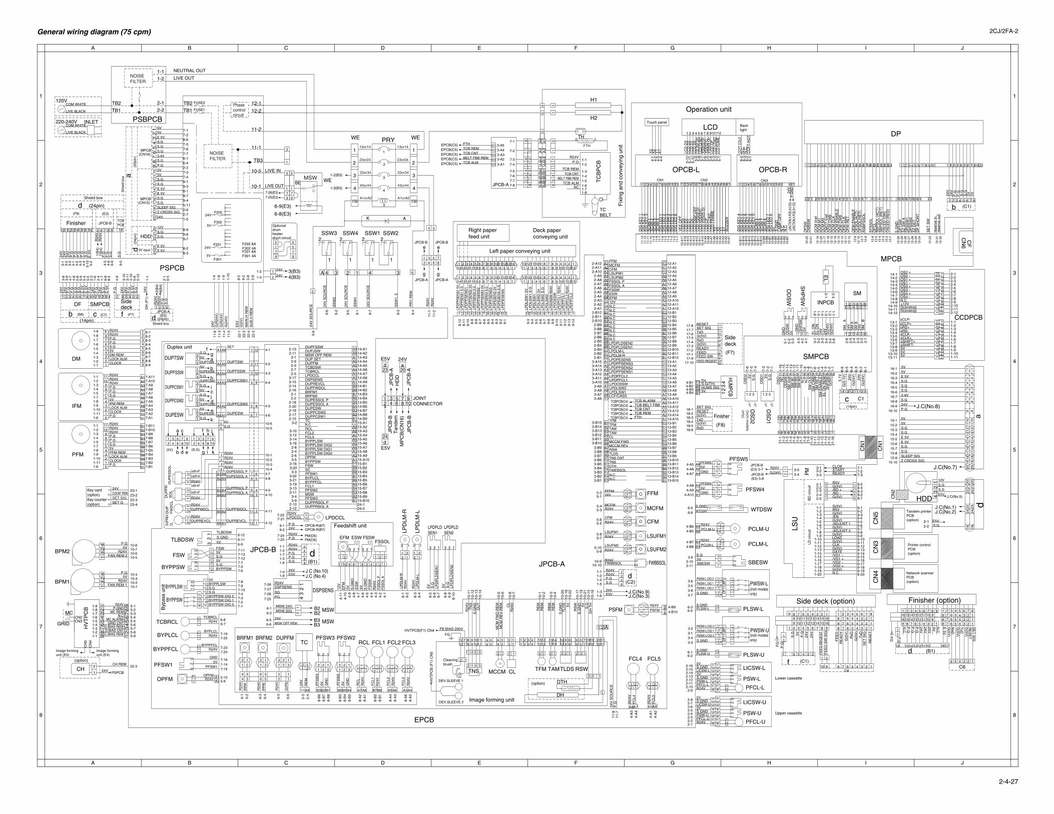
A B C D E F G H I J
A B C D E F G H I J
1
2
3
4
5
6
7
8
1
2
3
4
5
6
7
8
General wiring diagram (75 cpm) 2CJ/2FA-2
2-4-27
13or14
43or44
23or24
33or34
A1orA2
13or14
43or44
23or24
33or34
A1orA2YW YW
4
5
3
2
1
AK
WE WE
Phasecontrolcircuit
11-2
12-2
12-1FUSE2
FUSE1TB1
TB2
TB1
TB2
aS
hiel
d bo
x
(CN16)MPCB
(CN15)MPCB
NOISEFILTER
NOISEFILTER
WEBE
7-25(E3)7-26(E3)
6-8(E3)
6-9(E3)
Optionaldrumheatershort circuit
5V
5V
24V
24VF201 8A F301 4A
F202 8A F302 4A
1-3(B3)
1-2(B3)
EPCB(C5)EPCB(C5)EPCB(C5)EPCB(C5)EPCB(C5)
P.G
P.G
P.G
24V
24V
S.G
7-27-1
7-7
7-6
FSW
S.G5V
5VS.GBYPPSW
5VBYPPLSWS.GS.G
3 13
26
54
21
32
1
76
54
32
132
1
Byp
ass
unit
7-37-47-107-97-8
7-5
7-127-137-11
BYPPSW DIG 2
BYPPSW DIG 0BYPPSW DIG 1
12
34
4-B3
7-25
4-B4
4-B14-B2
43
2
S.G(TH)
1
TH
HUMS SIG5V
WTDSWS.GND
RE
M24
V
PGSG
DSPSENSR24V
7-277-28
7-26
1
2
Finisher
P.G
24V
S.G
DF SMPCB
b
S.G
S.G
P.G
P.G
24V
24V
98
76
54
32
1
Printer controlPCB(option)
7-37-27-1
8-58-48-38-28-1
PM
LD c
ircui
tB
D c
ircui
t
3-5READYSTARTCLOK
3-23-1
3-4 3-3
G(5V)/BD -/BD +G(5V)R5V
2-32-22-1
2-42-5
1-131-121-111-101-9
1-31-21-1
1-41-5
1-8
1-61-7LS
U
HDD
2-12-22-32-42-52-62-7
1-11-21-31-41-51-61-71-81-91-101-11
CCDPCB
1 2 3
1 2 3 4 5 6
1-4
G(5
V)
(Inch models
only)
1-6
1-3
3-4
3-5
3-6
1-21-1
3-1
6-4
6-3
6-2
6-1
G(2
4V)
24V
SMPCB
21-1
521
-16
5-1
5-2
5-3
5VOD
SW
GN
DO
DS
WS
M V
ref
SM
M1
1-13
1-14
4-3
4-2
4-1
GN
DS
HP
SW
5VS
M M
3N
.C
SM
CLK
SM
CW
BS
M R
ET
SM
EN
AB
LEE
L O
N R
EM
SH
PS
W
1 2 3
3-2
3-3
24V
G(2
4V)
G(2
4V)
EL
ON
EL
ON
24V
1-51-4
2-1
2-2
2-3
2-4
2-5
2-6
SM
_ B
24V
SM
BS
M A
24V
SM
_ A
1-12
1-11
1-10
1-9
1-8
1-7
1-6
1-5
1-3
1-2
1-1
SM
M2
2-1
2-4
INPCB
SM
EL
DUPESW
DUPTSW
DUPPCSW1
SET
S.G
S.G
5V
5VDUPESW
5VS.G
DUPTSW
DUPESSW
DUPPCSW1S.G5V
FFM
MCFM
CFM
LSUFM1
LSUFM2
FWBBSOL
21
34
62
5
1
(20p
in)
A
A 4 3 4 32 1
4
3
2
1
4
3
2
1
9-8
9-3
9-5
4-5
4-6
6-6
5-2
4-2
4-3
5-104-4
4-1
3-3
3-2
3-1
6-5
2-1
1-1
5-12
3-10
3-11
4-10
5-6
4-9
8-4
2-3
1-6
2-4
1-7
5-8
5-9
5-5
5-4
4-7
4-8
3-9
3-8
2-9
2-8
9-2
8-5
1-9
1-10
1-8
1-4
24V1-5
8-38-2
8-99-69-7
2-7
9-45-112-6
9-38-18-7
9-17-47-3
6-16-42-2
7-57-67-7
8-67-27-1
J.C (No.4)J.C (No.10)
J.C(No.3)J.C(No.9)
J.C(No.5)
J.C(No.2)J.C(No.1)
J.C(No.7)
J.C(No.8)M
PC
B(C
N16
)T
ande
mH
DD
JPC
B-B
JPC
B-B
JPC
B-A
JPC
B-A
24V
E5V
E5V
20a
d24
d23
JOINT CONNECTOR
9108
76453
21
11
Shield box
Shield box
d98743
d6521
1716
11
19 15 14 13 1211 10
2020
d99
1818
E5V
(24p
in)
d 5V input
2423
E 5VE 5V
P.G
P.G
S.G
S.G
181917
65
43
21
(24pin)
(24pin)d
P.GR24V
TCB ALMBELT FBB REM
TCB CNTTCB REM
MSW
MSW
N.C
JPCB-B (E3) 5-8
JPCB-B (E3) 5-7
1516 1413121110 9 8 7 6 5 4 3 2 11 2 3 4 5 6 7 8 910111213141516
16151413121110987654321
JPCB-B JPCB-B
JPCB-A JPCB-A
910 8 7 6 5 4 3 2 1
9-149-159-169-179-189-199-20
9-139-129-119-109-9
9-39-29-1
9-49-5
9-8
9-69-7
DATE
CLK
LOAD
N.CG(5V)
G(5V)
G(5V)
G(5V)
G(5V)
G(5V)
G(5V)
G(5V)
/VD2 -/VD2 +
/VD1 -/VD1 +
/EN
/ADJUST 2
/ADJUST 1
R5V
HV
TP
CB
(F
1) C
N5 (B1)
(C1)
1 6 5 4 3 2
TCBPCB(C4)TCBPCB(C4)TCBPCB(C4)TCBPCB(C4)
87654321
JUNC
TION
A PC
B (9-
1 E3)
JUNC
TION
A PC
B (9-
2 E3)
(C1)
(E3)(F8)
(E5)(F7)(B8) (C7)
C1
12345678910111213
12345678910111213
13121110987654321
131211109876543211234567891011121314
1234567891011121314
1413121110987654321
1413121110987654321
e e
gg
(C2)
R24V
JPCB-A
S.G
P.G
8(B
4)2(
B4)
R24
VR
24V
(B1)
24V5V
7(B
4)1(
B4)
R24
VR
24V
JPCB-B
15 1614131211
TCBPCB
HDD S.GS.G12V
E 5V
S.G3.4VS.GS.GS.G
5V5V
E 5VE 5V
S.GS.G
S.GS.G5V
P.G5V
Z CROSS SIGSLEEP SIG
HVTPCB(F1) CN4
Image formingunit (E4)
Image formingunit (E4)
10-510-6
10-410-310-210-1
4(B3)3(B3)
B3B3B2B2
30292827262524 232221 20191817161514131211 10 9 8 7 6 5 4 3 2 1
(F8)
C6
(F7)
TCBPCB(C4)
PM(D6)
OPCB-R(B7)
87
6453
21
2122
2324
2019
1817
1615
1413
1211
106
78
2122
2324
2019
1817
1615
1413
1211
106
78
CN
2
S.GS.G
S.GS.G
S.GS.G
E 5V
E 5VE 5V
5V
5V5V
15-5
S.G
12-3
2re
serv
e ou
tre
serv
e in
12-3
1
242322212019181716151413121110987654321 10
5V
201918171615141312
S.G
ND
12-3
0
12-2
112
-22
12-2
3
12-2
412
-25
12-2
612
-27
12-2
812
-29
12-1
12-2
12-3
12-4
12-5
12-6
12-8
12-7
12-1
012
-9
12-1
212
-11
12-1
412
-13
12-1
612
-15
12-1
812
-17
12-2
012
-19
DP
TS
WS
Z S
W A
DP
SS
W1
SE
T S
W
DP
SS
W2
SZ
DE
TD
P S
HO
RT
OF
SW
OS
BS
W
119874 65321
b
S.G
5VP.G
P.G24V
24V
RS
BF
SS
OL
OF
SO
L(R
ET
)O
FS
OL(
AC
T)
OF
M C
LKO
FM
CW
BO
CM
EN
AB
LEO
CM
CLK
OC
M C
WB
CM
OT
Vre
fO
CM
M3
DP
OS
LED
(R
ED
)O
SLE
D (
GN
)S
BP
SO
L (R
ET
)S
BP
SO
L (A
CT
)O
FC
LE
FS
SO
L
OF
M E
NA
BLE
OF
M R
ET
OC
M M
1O
CM
Vre
f
10-1010-9
5-105-9
5-85-7
5-65-5
5-45-3
5-25-1
123456789101112
9-13
9-149-4
9-5
9-6
9-7
9-8
9-9
9-10
9-11
9-12
121110987654321
4-1
4-2
4-3
4-4
4-5
4-6
4-7
4-8
4-9
4-10
4-11
2 11 2
122 1
E5V
S.GP.G
24V
R24V
1-6
1-51-4
1-3
1-21-1
3-B103-B113-B123-B133-B143-B15
A14A13A12A11
A10A9A8A7A6A5A4A3A2
A15
A1
B15B14B13B12B11B10B9B8B7B6B5B4B3B2B1
B13B14B15
B12B11B10B9B8B7B6B5B4B3B2B1
A13A14A15
A1A2A3A4A5A6A7A8A9A10A11A12
B12B11B10B9B8B7B6B5B4B3B2B1
A1A2A3A4A5A6A7A8A9A10A11A12
B10B11B12
B1B2B3B4B5B6B7B8B9
A10A11A12
A1A2A3A4A5A6A7A8A9
PM(D6)
OPCB-R(B7)
P.G7-23
R24V7-24
24V9-2
P.G9-1
7-217-22
A9A10
A2A1
123123
P.G
E5V
S.G
P.G
24V
R24VR24V
1-8
1-61-51-7
1-4
1-21-1
R24VFWBBSOL
3-20B10
B3B2B1
B7B8
B4B5B6
B9
B3B2B1
B7B8
B4B5B6
B9
A10
A3A2A1
A7A8
A4A5A6
A9
A3A2A1
A7A8
A4A5A6
A9
PFSW3MSW
DUPPRSOL ADUPPRSOL P
PFSW2FCL1BYPPFCLBYPLCLPFSW1SCFSWBYPPSWOPFM
N.C
BYPPLSW DIG0BYPPLSW DIG1BYPPLSW DIG2BYPPLSWFCL3FCL2RCL
TCDUPPCSW1DUPPCSW2DUPESWDUPESSOL ADUPESSOL P
BRFM1BRFM2
DUPFWDCLDUPREVCLDSPSENSLPDCCLTCBRCLTCBDSWDUPFMDUP SETMSW OFF REMDUPJSWDUPFSSW
A3A4A5A6B7B8
B1
B2
A7A8
2 121
2 121
2 121
1221
CFMR24V
FFFM24V
LSUFM2R24V
MCFMR24V
N.CN.CFWEBSOLDTHTNSTNS CNTTLDSRSWMCCM REVMCCM FWDCLTAMTAMTFMTFM
13-B1413-B15
6-96-116-12
LPDLSW1LPDLSW2LPDOSSW
FTHTCB REMTCB CNTTCB BELT FBBTCB ALARM
LCF/CASS
LPDPFCL1LPDPFCL2LPDPPSENS1LPDPPSENS2LPDPPSENS3LPDPESENSLPDLM-RLPDLM-LLPDPLDSEN1LPDPLDSEN2
N.CN.C
N.CN.C
N.CN.CN.CN.C
2-A12
12-A12N.C12VEFMESWFSSWFSSOL AFSSOL PLSUFM2LSUFM1CFMMCFMFFM
22-3
OS
D2
5V S.G
21-1
21-2
21-3
21-4
21-5
21-6
21-7
21-8
21-9
21-1
021
-11
21-1
221
-13
21-1
4
FEED SWFEED REQEST
11-7
11-8
10-410-3
10-110-2
9876543219
12345678
B10B9B8B7
212
11221
FC
L5R
24V
4-A10
4-A7
4-A84-A9
4-A64-A5
GND5VPFSW4
4-B54-B6
4-B74-B8
2-92-102-112-122-132-142-152-16
2-12-22-32-42-52-62-72-8
6-26-1
3-33-43-13-2
6-46-3
3-73-83-53-6
3-113-103-9
1-141-151-161-171-181-191-20
8-A
58-
A6
8-A
38-
A4
8-B
18-
B2
8-A
18-
A2
8-B
58-
B4
8-B
3
8-B
88-
B7
8-B
6
5-4
5-3
6-6
6-4
6-3
6-2
6-1
6-5
8-1
8-2
8-3
8-4
8-5
8-6
8-7
8-8
8-9
8-10
8-11
8-12
4-A
24-
A1
4-A
44-
A3
6-106-
96-
8
6-4
6-3
6-7
6-6
6-5
6-2
6-1
10-1
610
-15
10-2
110
-19
10-1
7
10-2
210
-18
10-2
0
10-4
10-3
10-2
10-1
10-7
10-8
10-6
10-5
10-1
410
-13
10-1
210
-11
2-112-13
3-12-92-32-72-5
3-173-152-142-162-12-2
2-182-202-192-172-15
3-2
3-103-123-143-182-82-42-63-5
3-16
3-33-223-213-193-133-113-43-9
2-102-12
DUPFMBRFM2
OPFM
PFSW1
BYPPFCL
BYPLCL
TCBRCL
BYPPSW
BYPPLSW
BYPPSW
FSW
TLBDSW
DSPSENS
5-95-10
7-157-147-16
7-247-23
7-207-19
6-76-8
4-12
4-11
4-104-9
4-84-7
4-6
4-5
4-4
4-3
4-2
4-1
3-B73-B83-B9
3-A93-A103-A113-A123-A133-A143-A15
3-B13-B23-B33-B43-B53-B6
2-A22-A1
2-A32-A42-A52-A62-A72-A82-A9
2-A102-A11
2-B12-B22-B32-B42-B52-B62-B72-B82-B9
2-B102-B112-B12
3-A1
3-A23-A33-A43-A5
3-A63-A73-A8
P.G
161514131211109
FEE
D R
EQ
ES
TF
EE
D S
W S
IG
RE
SE
T
SE
T S
IGT
xDG
(5V
)R
xDG
(5V
)R
EA
DY
FE
ED
S.G 5V 24V
24V
P.G
8 7 6 5 4 3 2 1
8 7 6 5 4 3 2 1
9
f
FG
2 3 4 5 6 7 8 91
1 2 3 4 5 6 7 8
9 10 11 12 13 14 15 168 7 6 5 4 3 2 18 7 6 5 4 3 2 1
Side deck (option)
17-917-10
910
Network scannerPCB(option)
15-215-1
15-415-3
16-6
16-10
16-716-816-9
CN
6C
F
13-B1213-B13
13-B713-B813-B913-B1013-B11
13-A913-A1013-A1113-A1213-A1313-A1413-A1513-B113-B213-B313-B413-B513-B6
12-A212-A1
12-A312-A412-A512-A612-A712-A812-A912-A1012-A11
12-B112-B212-B312-B412-B512-B612-B712-B812-B912-B1012-B1112-B1213-A113-A213-A313-A413-A513-A613-A713-A8
14-A214-A1
14-A314-A414-A514-A614-A714-A814-A914-B114-B214-B314-B414-B514-B614-B714-B814-B915-A115-A215-A315-A415-A515-A615-A715-A815-A915-A1015-B115-B215-B315-B415-B515-B615-B715-B815-B915-B1024-124-2
JPCB-A
JPCB-B
2 11 2
2 11 2
2 11 2
2 11 2
21
R24VLSUFM1
LPD
LM-L
R24
V
1221
R24
VLP
DLM
-RLP
DLM
-R
LPD
LM-L
5V S.G
LPD
PLD
SE
N1
LPD
PLD
SE
N2
S.G
5V
RC
LR
24V
FC
L1R
24V
FC
L2R
24V
3 2 1
21
EFM ESW FSSWFSSOL
LPDPLDSEN1
LPDPLDSEN2
1 2 3
TC
98
76
54
32
1
12
34
56
78
9
7-87-77-67-5
7-47-3
7-2
7-1
JPCB-A
10-B
1610
-B17
10-A
17
11-1
311
-12
11-1
111
-10
11-9
11-8
11-7
11-6
11-5
11-4
11-3
11-2
11-1
10-B
1510
-B14
10-B
1310
-B12
10-B
1110
-B10
10-B
910
-B8
10-B
710
-B6
10-B
510
-B4
10-B
310
-B2
10-B
1
10-A
1610
-A15
10-A
1410
-A13
10-A
1210
-A11
10-A
1010
-A9
10-A
810
-A7
10-A
610
-A5
10-A
410
-A3
10-A
210
-A1
Backlight
CC
FT
HO
TN
.CN
.CCC
FT C
OLD
6-4
6-3
6-2
6-1
LCD
VS
S(S
.G)
CN1
5-9
5-10
5-11
5-12 5-5
5-6
5-7
5-8
5-1
5-2
5-3
5-4
4-4
4-3
4-2
4-1
X1
Y1
X2
Y2
N.C
N.C
BU
ZZ
ER
17
DIG
LE
D 6
13121110987654321
DIG
LE
D 4
DIG
LE
D 3
DIG
LE
D 2
DIG
LE
D 1
SC
AN
4
DIG
KE
Y 3
DIG
KE
Y 2
SC
AN
2S
CA
N 1
DIG
LE
D 5
DIG
KE
Y 1
SC
AN
3
LCD
CO
NT
LCD
DISP
OFF
CN2 CN3
Operation unit
VS
S(S
.G)
LCD
FLAM
ELC
D L
OA
DLC
D C
P
LCD
D0
LCD
D1
LCD
D2
LCD
D3
16151413121110987654321 1415 171613121110987654321
DIG
LE
D 8
DIG
KE
Y 4
SC
AN
7
5VLCD
LO
AD
LCD
CP
LCD
VS
S(S
.G)
LCD
VD
D(5
V)
LCD
D2
LCD
D3
LCD
D0
LCD
D1
12111098765432
S.G
ND
1
Y2
X2
VD
D(5
V)
VS
S(S
.G)
Y1
LCD
FR
AM
E
X1
24V
P.G
ND
LAM
P O
FF
Touch panel
VE
E O
FF
LCD
DIS
P O
FF
DIG
KE
Y 8
SC
AN
5D
IG K
EY
9
SC
AN
8D
IG L
ED
7
DIG
KE
Y 5
DIG
KE
Y 6
DIG
KE
Y 7
SC
AN
6
LCD
OPCB-ROPCB-L
6 56 5
1-8
123321
1212
42
31 1
3
12
34
11201120
21
24V PSPCB
DH
(F
1)24
V
42
31
9 8 7 6 5 4 3 2 1 8 7 6 5 4 3 2 1
NC
14-1114-1014-914-814-714-614-514-414-314-214-1
LPDCCL
2
Deck paperconveying unit
DH
(option) DTH
26 5 4 3 1
16 1514 13 12 11 10 9910111213141516
9876543211234567812345678
C6
P.G
P.G
FG P.G
N.C
N.C
P.G
24V24V
G(5V
)E
5V
1 2 3 4 5 6 7 8
d
RxD
G(5V
)T
xDG
(5V)
SE
T S
IGR
ES
ET
Finisher (option)
B5B6
B4B3
12
21
12
21
R24VPCLM-L
R24VPCLM-U
Sidedeck
87
65
43
21
32
2122
1718
1920
20
12
11
10
9
8
7
65
43
2
1
15-715-6
3.4V
CH
(option)
1
CN
5C
N3
CN
4
P.G
24V
SO
UR
CE
123
12
3
321
9713
79
3
77
S.G
OS
D1
1 2 3
3 1
21
24V
24V
1-3
1-2
1
F202
F201
F302
F301
1 2 3
2
A3
A4
A5
A6
B6
B5
B4
B31
23
45
67
8
B3B4
B2
B5
B1
B6
A4
A3
A5
A2
A6
A1
1110
98
76
54
32
112
1110
98
76
54
32
1
A9
5V
Right paperfeed unit
Left paper conveying unit
CH REM
6 4 3 25
12
3 PFSW15V
GND
6-56-6
1
9
3
1
S.G2-22-1
Tandem printerPCB(option)
FEEDREADYG(5V)RxDG(5V)TxDSET SIGRESET
R24VOPFM
12
11
109
87
6
5
4
3
2
1
(S.G)(5V)
1
31
9
3
1
3
1
B2
B1
k
j
i
h
gf
e
d
c
b
a
k
21 3
4 65 9
10879
1087
j
i
h
g
f
ed
c
b
a
6453
21
E 5
VE
5V
E 5
V
E 5
V
E 5
V
10 987
Sidedeck
d
5V5V5VfSHIFT-fSHIFT+
fCLP-fCLP+
fRS-fRS+
fCLK-fCLK+
G(analog)G(analog)+12VN.COS4 -OS4 +OS3 -OS3 +OS1 -OS1 +OS2 -OS2 +
14-12
13-1113-1013-913-813-713-613-513-413-313-213-1 11
109
87
65
43
21
1211
109
87
65
43
21
B4B5
A6A5A4
A3A2A1
B3B2B1 B6
A8A7 A10
R24VFAN REM 1
10-810-7
10-510-6
LPDCCL
11
6
2345789
10
A9A8A7A6A5A4A3A2A1
A2
A1
A3
A4
A5
DUPTSW
DUPPCSW1
DUPPCSW2
DUPESW
DUPFSSW
A6
B1B2
B3B4
B5
B6
4321
56
24V
P.G
24V
G(2
4V)
1314
P.G
24V
2-12
2-82-92-102-11
1516
1-15
1-16
OS
D N
C
6 5 4 3 2 1
654321
43
21
R24V
R24V
Latch-off
Latch-off
23
1
DUPPRSOL A
LPD
LSW
2
LPD
LSW
1 5V
LPD
PP
SE
NS
3
LPD
PP
SE
NS
2 5V
LPD
PE
SE
NS
5V
LPD
PE
SE
NS
S.G
LPD
PFC
L2 R
24V
LPD
PFC
L1 R
24V
LPD
OS
SW
R24
V
LPD
LSW
2 S
.GLP
DLS
W2
5VLP
DLS
W1
LPD
LSW
1 S
.G
LPD
PE
SE
NS
1516
P.G5V
P.G5V
FAN REM 2R24V
122
12
33
21
12
3PFSW55VGND
12
33
21
12
3
123321
123
PF
SW
35V G
ND
123321
123
PF
SW
25V G
ND
2 1 R24V
TCBRCL
12
34
512
34
5
R24
VF
CL3
R24
VF
CL4
1
5-7
S.G5V
R24V
R24VR24V
DUPREVCL
14 13
G(5
.1V
)5.
1V6-
66-
5
7-6
7-5
7-4
7-3
7-2
7-1
12V
E5V
S.GS.G
12
LPD
PP
SE
NS
1 5V
34
21
P.G
24V
R24
V
DUPF
M
1221
5656
R24
VBR
FM2
BRFM1
1221
3434
R24
VBR
FM1
4-B104-B9
PSFM
12
21
R24VPSFM
LIVE OUT
LIVE IN
43
21
43
21
14
312
DUPR
EVCL
DU
PF
WD
CL
21
DUPREVCLR24V
21
DUPFWDCLR24V
6-2MSW SIG
6-1MSW 24V
4321
(14pin)
12111098765
(14pin)
87
65
43
21
17-1
17-4
17-217-3
17-517-617-717-8
c
18-618-518-418-318-218-1
MSW
Finisher
RxDG(5V)TxDG(5V)
SET SIGRESET
111098
DEV.SLEEVE 2
B4
B3
A4
A3
A2
A1
SH
PS
W
OD
SW
OS
D1
OS
D2
HUMPCB 12 11 10 9
c
1413121110 9 8 7 6 5 4 3 2 1
1310
1112
P.G
R24V
S.G5VDM REMLOCK ALMCLOCK
R24V
P.G
FG
FB BIAS 200V
1919
1818
3412
LPDP
PSEN
S1 S
.G
321
3
21
321
32
1
DUPPCSW2
S.G5VDUPPCSW2
1-6
11108 91212
77 34
22
11
43214321
15 131315
1010
66
77
11
1212
1414
55
9 89 8
7-A8
7-A10
P.G
R24V
1-9
11-101-11
1-21-1
8-88-9
CN
1
CN
1
24V
P.G
S.G
f
11-6
24V
FTH
DUPFSSW24
V S
OU
RC
E
24V
SO
UR
CE
Duplex unit
8-78-68-58-48-38-28-1
P.GS.G5VIFM REMLOCK ALM
R24V
R24V
35
4
65
32
14
1-71-61-51-41-3
1-2
Fix
ing
and
conv
eyin
g un
it
Feedshift unit
S.G
4
5-15-25-35-45-55-6
5-85-9
1
DH
TH
S.G
PSW-LS.GND
S.GND
5V
5V
PFCL-LR24V
12
31
23
21
12
34
56
78
41
23
56
78
LICSW-L
PSW-US.GND
S.GND
5V
5V
LICSW-U
Upper cassette
Lower cassette
PSW-U
PFCL-U
LICSW-L
PLSW-U
PLSW-L
PWSW-U
PWSW-L(inch modelsonly)
(inch modelsonly)
SBESW
PCLM-L
PCLM-U
WTDSW
PFSW4
PFSW5
PSW-L
PFCL-L
PFCL-UR24V
12
31
23
21
12
34
56
78
41
23
56
78
LICSW-U
12
4PWSW-U DIG 0
PWSW-U DIG 2S.GND
PWSW-U DIG 1
12
3
DF
11(8
P)
65
87
43
21
12
CN3CN2
CN
4C
N5
1
2 3 12 1
TLD
SS
.GN
D 5V
RE
MR
EM
RE
MR
EM
LPD
PF
CL2
LPD
PF
CL1
LPD
OS
SW
R24V
LPDP
PSEN
S3 S
.GLP
DP
PS
EN
S3
5VLP
DP
PS
EN
S2
LPDP
PSEN
S2 S
.G
LPD
PP
SE
NS
1
9-6
9-1
SS
W4
2SSW2SSW1SSW4SSW3
1
9-3
SS
W1,
2
1
2
1
2 2
1
9-7
9-2
SS
W3
24V
SO
UR
CE
9-5
12
3SBESW5V
CL
R24
V
11-3
G(R
24V
)
11-1
FSS
OL
A7-A9
7-A11
7-A37-A4
A11A10
CLOCKP.G 7-A1
7-A2
7-A57-A67-A7
R24
V
11-1
NEUTRAL OUT
COM WHITE
LIVE BLACK
COM WHITE
LIVE BLACK
INLET220-240V
120V
233 1 2 1
1-71-8
1-11-2
1-51-41-3
11
6
2345789
10
B9B8B7B6B5B4B3B2B1
1-6
7-B8
7-B10
P.G
R24V
1-9
11-101-11
P.GS.G5VPFM REMLOCK ALM
R24V
R24V 7-B9
7-B11
7-B37-B4
B11B10
CLOCKP.G 7-B1
7-B2
7-B57-B67-B7
1-71-8
1-11-2
1-51-41-3
1-41-3
1-91-8
1-51-61-7
21
21
FCL3FCL2FCL1RCLPFSW2PFSW3
FCL5FCL4
R24VBYPLCL
R24VBYPPFCL
PLSW-US.GND
S.GNDPLSW-L
4PWSW-L DIG 2
PWSW-L DIG 2S.GND
PWSW-L DIG 1
12
3
DF
11(8
P)
65
87
43
21
3 2 1
EF
M12
V
10 9 12678
5V ES
WS
.GN
D
345
5V R24
VFS
SO
L P
FS
SW
S.G
ND
S.GNDTLBDSW
5V
1TC BELT
TC
BP
CBTCB ALM
BELT FBB REMTCB CNT
1-1
TCB REM
MC S.G
ND 5V
Image forming unit
2 1
2 1
CLMCCMTNS
Cleaningbrush
DEV.SLEEVE 1
RSWTLDSTAMTFM
1-91-8
1-4
S.G
ND
OU
T
R24
VT
NS
C.BIAS REMD.BIAS CNTD.BIAS REM M
CM
FW
D R
EM
MC
M R
EV
RE
MR24V
1-7
GRID CNT
1-6 MC ALARM
P.GND
1-21-1
HV
TP
CB
1-3GRID
BPM1
BPM2
PFM
IFM
DM
Key card(option)Key counter(option)
1-5
MC REMN.C
RS
W
5 5
16-1
16-5
Z CROSS SIG
16-216-316-4 S.G
SLEEP SIG
5V
Lacth-on
3 DUPESSOL A
SU
B.H
RE
MM
AIN
.H R
EM
G(24V)R24V
9-4
9-8
6-66-5
22-5
11
12
TH
H1
H2
FTH
2 1
LIVE OUT
PR
Y R
EM
24V
SO
UR
CE
24V
PSPCB
PSBPCB
R24
V11
-2
10-1
10-5
2-22-1
1-21-1
TB3
15-1015-915-8
S.G
P.G24V
a
G(R
24V
)
G(5
V)
E5V
G(2
4V)
22-4
11-4
22-2
22-1
11-5
MPCB
EPCB
23-423-323-223-1
MSW OFF REM
DUPESSOL P
DUPPRSOL P
DUPFWDCL
Latch-off
R24V
43
2
SET G
24VCOUNT REMSET SIG
1
21DU
PE
SS
OL
PRY
DU
PP
RS
OL