kwik bond polymers high friction surface treatment · keith w. anderson. december 2015. mark...
TRANSCRIPT
December 2015Keith W. Anderson Mark Russell Jeff S. Uhlmeyer Jim Weston
WA-RD 851.1
Office of Research & Library Services
WSDOT Research Report
Kwik Bond Polymers® High Friction Surface Treatment
Experimental Feature Report __________________________________________________________
Final Report Experimental Feature 15-01
Kwik Bond Polymers® High Friction Surface Treatment QE9982 I-5 and I-90 High Friction Surface Treatment SR 526 EB to I-5 SB and 148th Avenue SE to I-90 WB
Engineering and Regional Operations Construction Division
State Materials Laboratory
Experimental Feature Report __________________________________________________________
December 2015 ii
1. REPORT NO. 2. GOVERNMENT ACCESSION NO. 3. RECIPIENT'S CATALOG NO.
WA-RD 851.1
4. TITLE AND SUBTITLE 5. REPORT DATE
Kwik Bond Polymers® High Friction Surface Treatment December 2015 6. PERFORMING ORGANIZATION CODE WA 15-01 7. AUTHOR(S) 8. PERFORMING ORGANIZATION REPORT NO.
Keith W. Anderson, Mark Russell, Jeff S. Uhlmeyer, and Jim Weston
. PERFORMING ORGANIZATION NAME AND ADDRESS 10. WORK UNIT NO.
Washington State Department of Transportation Materials Laboratory, MS-47365 11. CONTRACT OR GRANT NO.
Olympia, WA 98504-7365 12. SPONSORING AGENCY NAME AND ADDRESS 13. TYPE OF REPORT AND PERIOD COVERED
Washington State Department of Transportation Transportation Building, MS 47372
Post-Construction Report
Olympia, Washington 98504-7372 14. SPONSORING AGENCY CODE
Project Manager: Kim Willoughby, 360-705-7978 15. SUPPLEMENTARY NOTES
This study was conducted in cooperation with the U.S. Department of Transportation, Federal Highway Administration. 16. ABSTRACT
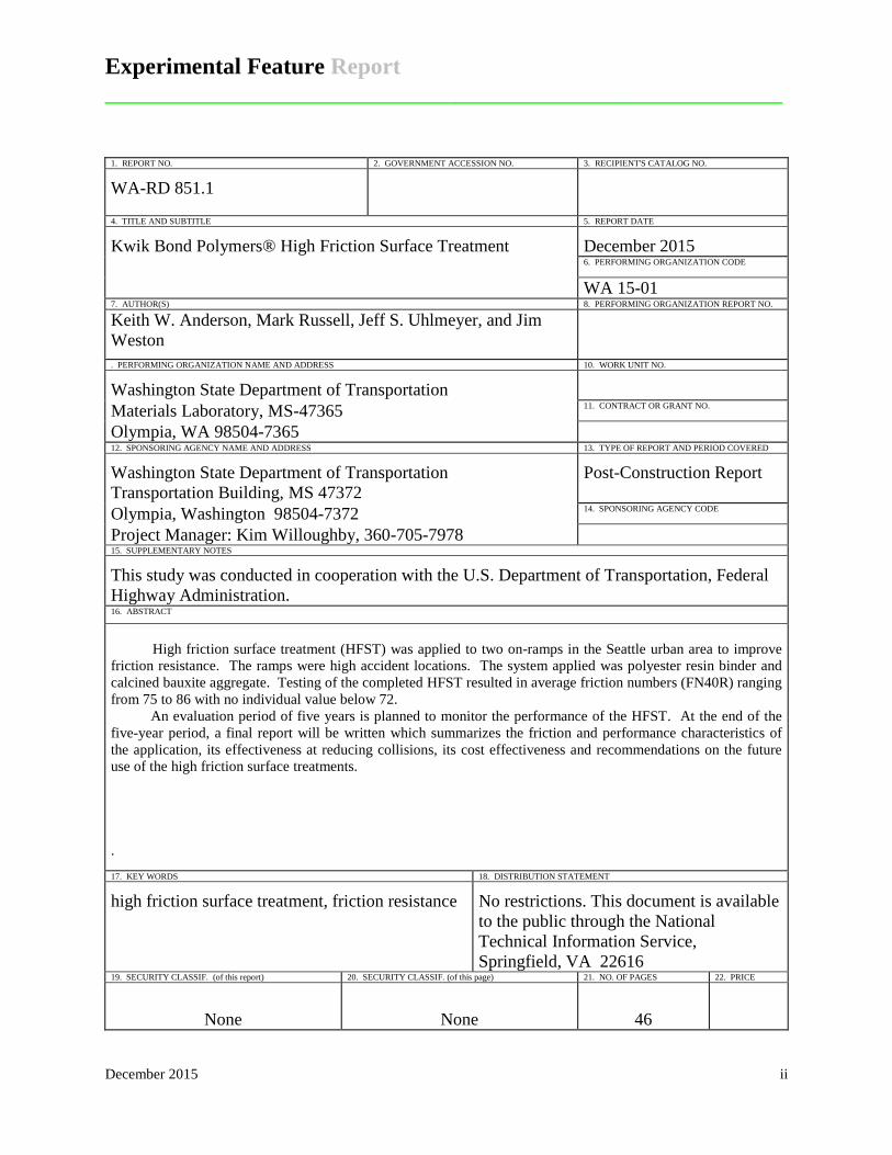
High friction surface treatment (HFST) was applied to two on-ramps in the Seattle urban area to improve
friction resistance. The ramps were high accident locations. The system applied was polyester resin binder and calcined bauxite aggregate. Testing of the completed HFST resulted in average friction numbers (FN40R) ranging from 75 to 86 with no individual value below 72.
An evaluation period of five years is planned to monitor the performance of the HFST. At the end of the five-year period, a final report will be written which summarizes the friction and performance characteristics of the application, its effectiveness at reducing collisions, its cost effectiveness and recommendations on the future use of the high friction surface treatments. . 17. KEY WORDS 18. DISTRIBUTION STATEMENT
high friction surface treatment, friction resistance
No restrictions. This document is available to the public through the National Technical Information Service, Springfield, VA 22616
19. SECURITY CLASSIF. (of this report) 20. SECURITY CLASSIF. (of this page) 21. NO. OF PAGES 22. PRICE
None None 46
Experimental Feature Report __________________________________________________________
December 2015 iii
DISCLAIMER
The contents of this report reflect the views of the authors, who are responsible for the
facts and the accuracy of the data presented herein. The contents do not necessarily reflect the
official views or policies of the Washington State Department of Transportation or the Federal
Highway Administration. This report does not constitute a standard, specification, or regulation.
Experimental Feature Report __________________________________________________________
December 2015 iv
TABLE OF CONTENTS Introduction ..................................................................................................................................... 1 Project Objectives ........................................................................................................................... 1 Project Location .............................................................................................................................. 1 Product Description ........................................................................................................................ 3 Construction Process ....................................................................................................................... 4 Post-Construction Testing ............................................................................................................... 9 Cost ............................................................................................................................................... 10 Discussion of Results .................................................................................................................... 10 Future Research ............................................................................................................................ 10 References ..................................................................................................................................... 10 Appendix A Contract Special Provisions .................................................................................... 11 Appendix B Manufacturer’s Certificate of Compliance .............................................................. 18 Appendix C Work Plan ................................................................................................................ 35
Experimental Feature Report __________________________________________________________
December 2015 v
LIST OF FIGURES Figure 1. HFST installation on SB 148th Avenue SE on- ramp to WB I-90. ............................... 2 Figure 2. HFST installation on EB SR 526 on-ramp to SB I-5. .................................................. 2 Figure 3. Inlet covered prior to HFST. ........................................................................................ 4 Figure 4. Lane line taped prior to HFST. ..................................................................................... 4 Figure 5. Taped expansion joint................................................................................................... 5 Figure 6. Diamond grinding to remove centerline stripe. ............................................................ 5 Figure 7. Application vehicle. ...................................................................................................... 5 Figure 8. Application vehicle, rear view. ..................................................................................... 5 Figure 9. Aggregate bin and circular bucket that service as the source for the augers which
distribute the aggregate. ................................................................................................ 6 Figure 10. Augers distributing aggregate across the width of the machine. .................................. 6 Figure 11. Binder storage tanks. .................................................................................................... 6 Figure 12. Binder is distributed through a number of rubber hoses to a ribbed plate. .................. 6 Figure 13. Red plastic squeegee protects ribbed plate from wear. Binder is spread on the
pavement followed by a curtain of aggregate. .............................................................. 6 Figure 14. Casting of aggregate onto wet spots to make sure of full coverage of the pavement. . 6 Figure 15. Clean-up operation, brushing excess binder and solvent into plastic trays. ................. 7 Figure 16. Suctioning excess binder and solvent from the trays. .................................................. 7 Figure 17. View of the HRST behind the paver on the I-5 section. .............................................. 7 Figure 18. Completed HFST, on-ramp to I-5. ............................................................................... 7 Figure 19. HFST on the left, original HMA on the right, on-ramp to I-90. ................................... 8 Figure 20. Completed HFST on the ramp to I-5. ........................................................................... 8
LIST OF TABLES Table 1. Physical properties of Kwik Bond PPC™HFST. ............................................................ 3 Table 2. Physical properties of calcined bauxite. .......................................................................... 4 Table 3. Project facts...................................................................................................................... 9 Table 4. Friction resistance before and after HFS treatment. ........................................................ 9
Experimental Feature Report __________________________________________________________
December 2015 1
Introduction Sharp curves can lead to higher than normal accident rates if the friction between tires
and the pavement is not sufficient to keep the car from skidding. Measures are taken to reduce
the number of accidents such as special warning signs and lowered speed limits. If these
measures are not effective the characteristics of the pavement are improved to increase friction.
The friction properties can be improved by replacing the pavement, placing a surface treatment
such as a chip seal over the existing pavement, or by grooving the pavement using diamond
grinding (concrete pavements). Replacing the pavement or diamond grinding are expensive
fixes. Chip seals are a less expensive solution than replacing the pavement or diamond grinding,
but may be prone to aggregate loss if applied on sharp curves due to a loss of bond between the
aggregate and binder. The alternative is to apply a thin, high friction surface treatment (HFST)
on the existing pavement. The special binders used for HFS treatments have higher bond
strengths than the asphalt binders used for chip seals. This is the alternative taken to improve the
friction resistance of two on-ramps in the Seattle urban area. HFST was part of FHWA’s Center
for Accelerated Innovation Every Day Counts program for 2012-2013(FHWA Every Day
Counts).
Project Objectives The three objectives of the study are:
• To measure the long-term performance of the HFST with respect to friction resistance, wear and aggregate retention.
• To measure any reduction in collisions.
• To develop a recommendation regarding the use of Kwik Bond PPC™HFST on WSDOT roadways.
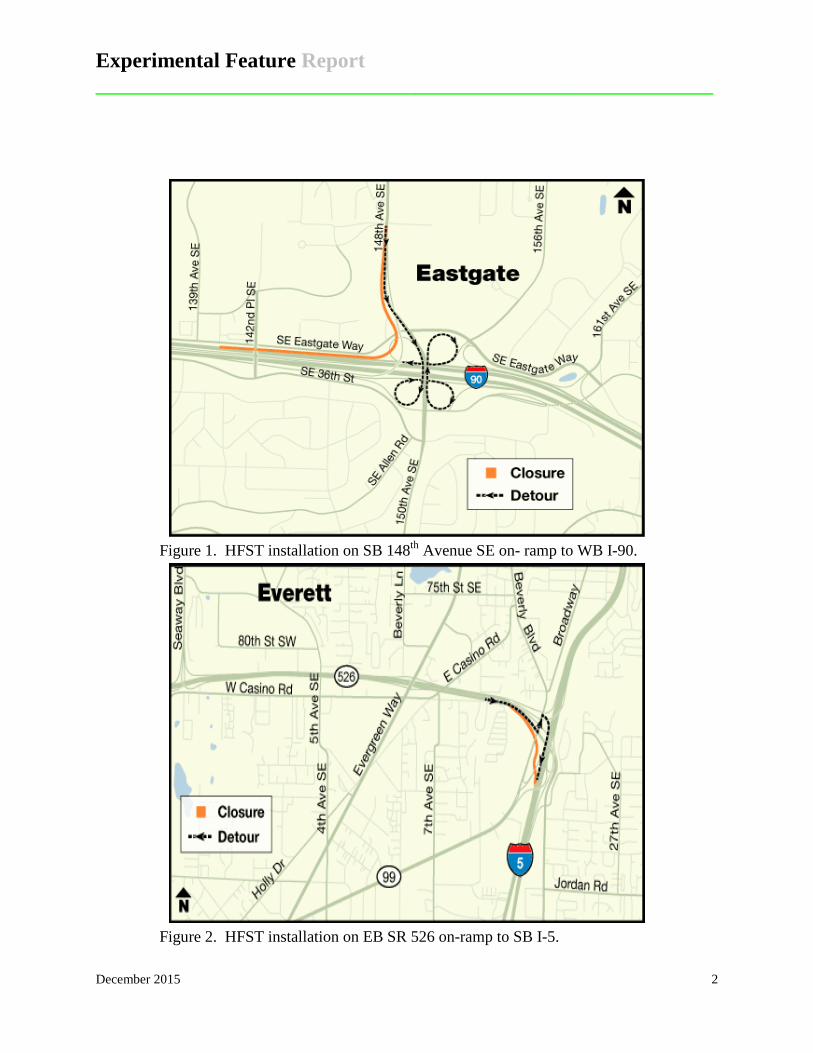
Project Location The two ramps are located on I-90 and I-5. The I-90 HFST was applied to the on-ramp
from 148th Avenue SE to westbound I-90 in Eastgate (Figure 1). The I-5 HFST was applied to
the on-ramp from SR 526 eastbound to I-5 southbound south of Everett (Figure 2).
Experimental Feature Report __________________________________________________________
December 2015 2
Figure 1. HFST installation on SB 148th Avenue SE on- ramp to WB I-90.
Figure 2. HFST installation on EB SR 526 on-ramp to SB I-5.
Experimental Feature Report __________________________________________________________
December 2015 3
Product Description The HFST system selected for this project was provided by Kwik Bond Polymers,
Benicia, CA. The system consists of a polyester resin binder and calcined bauxite aggregate.
Great Lakes Minerals, Wurtland, KT was the source of the bauxite aggregate. Kwik Bond’s
PPC™HFST is a polymer-based resin binder system designed specifically to get into the pores of
high friction aggregates and bond to various pavement substrates. The system can be mixed by
hand and applied with serrated squeegees, or with automated installation equipment which was
used on this project. The binder gains strength very quickly, so it can be applied to a roadway
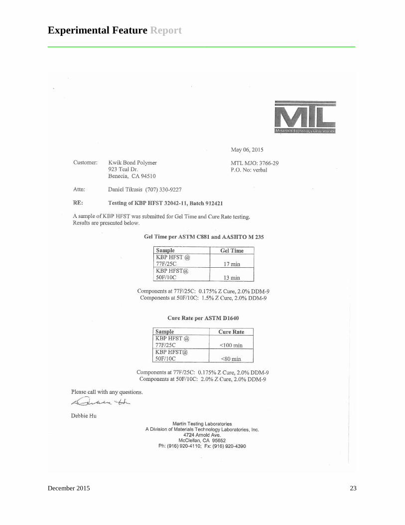
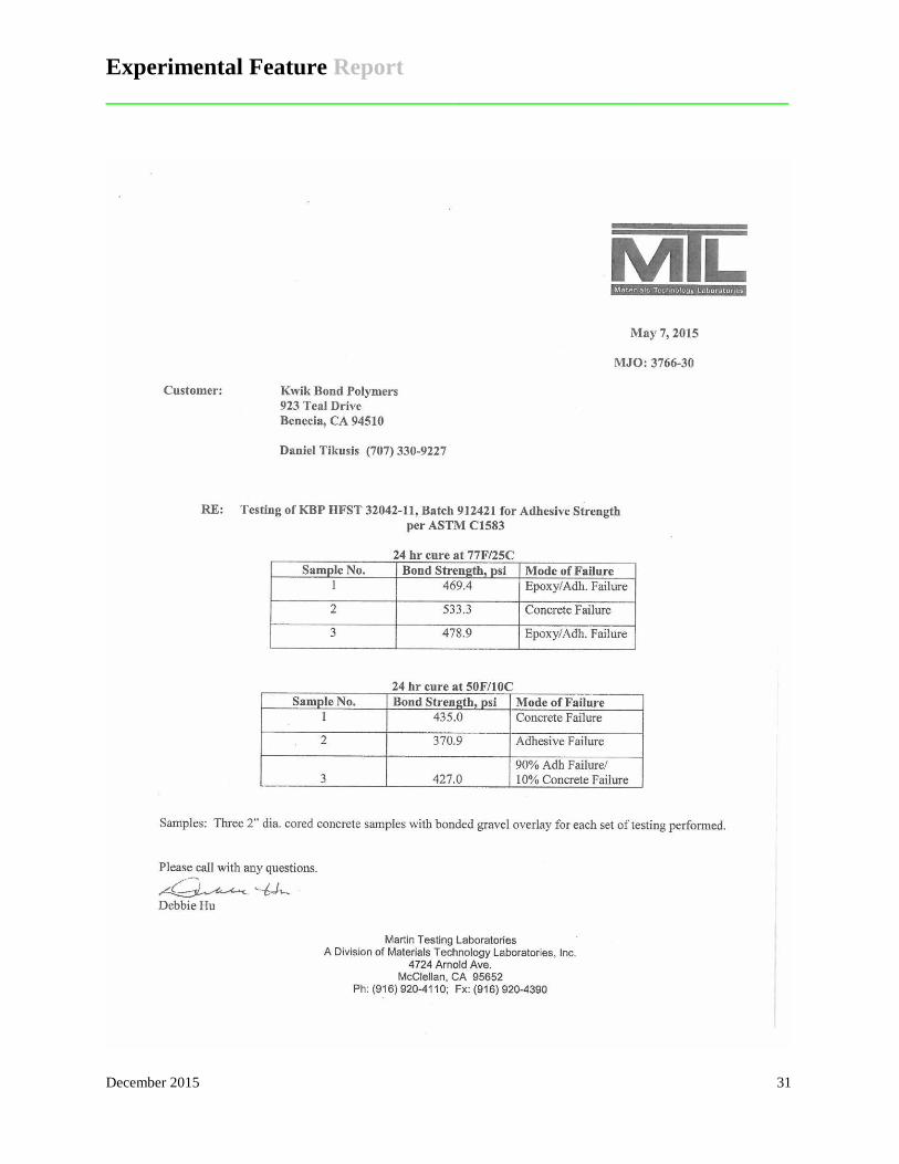
and returned to traffic within a normal production shift. The specifications and actual test results
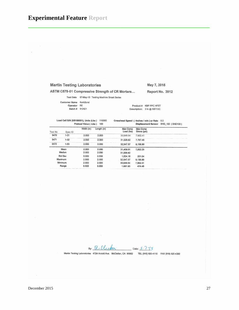
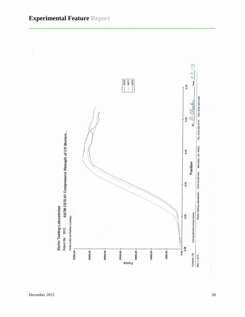
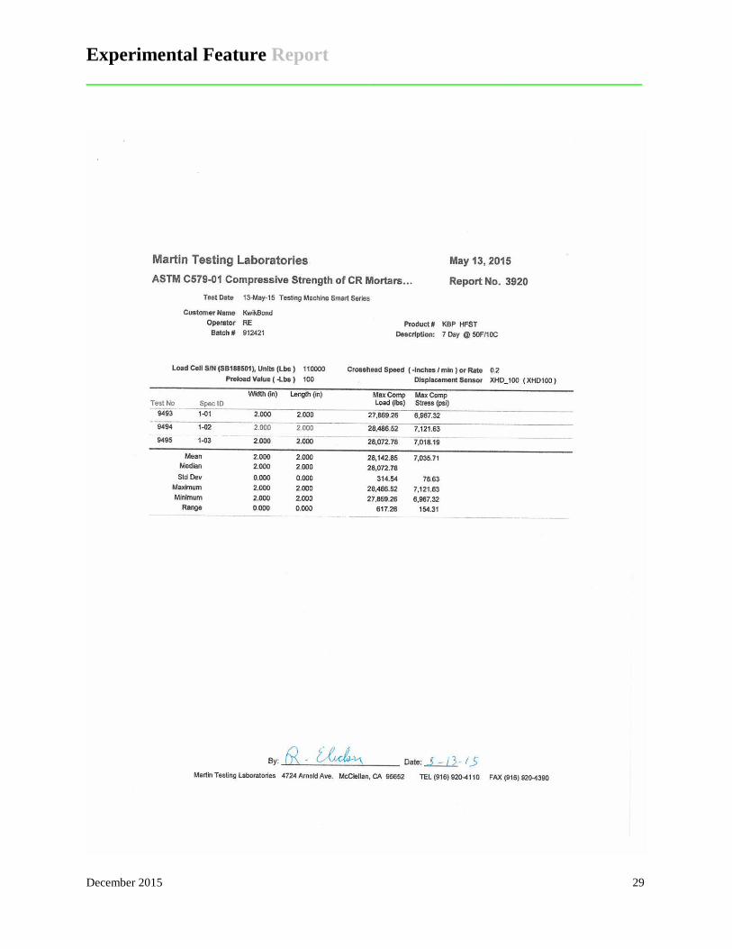
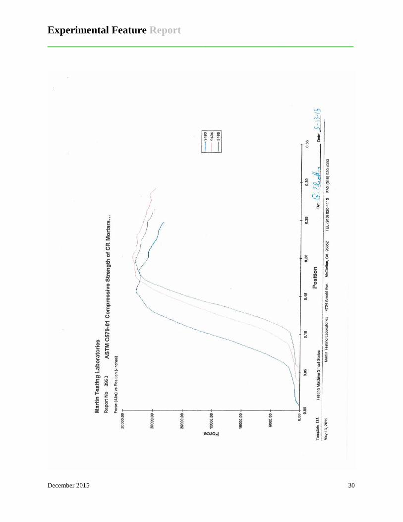
for the HRST are noted in Table 1 (see Appendix B for additional information).
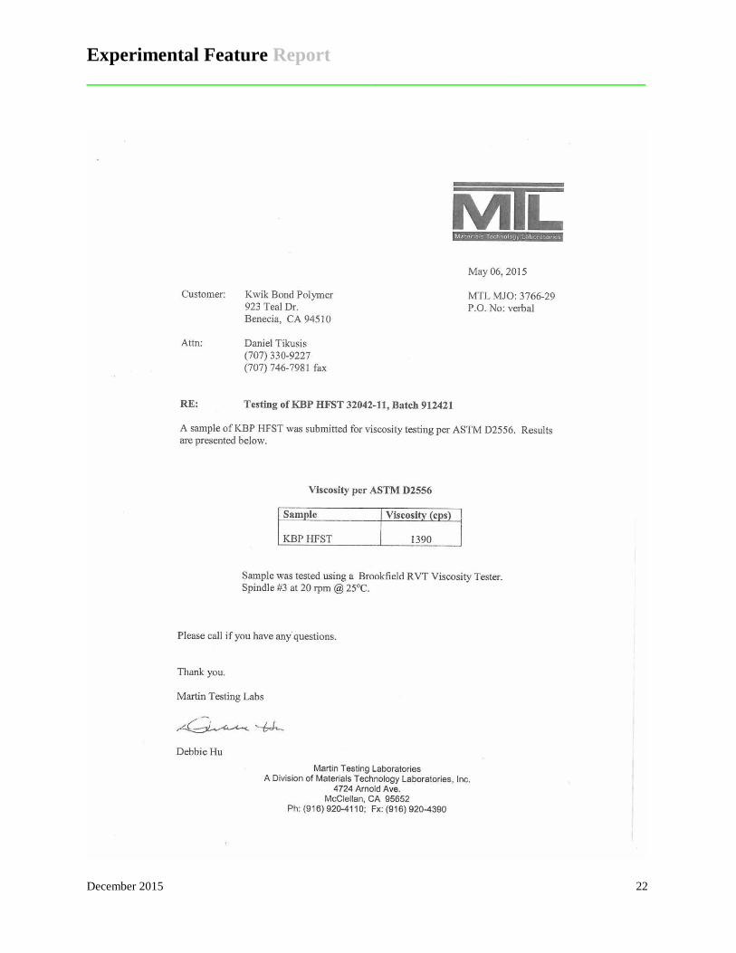
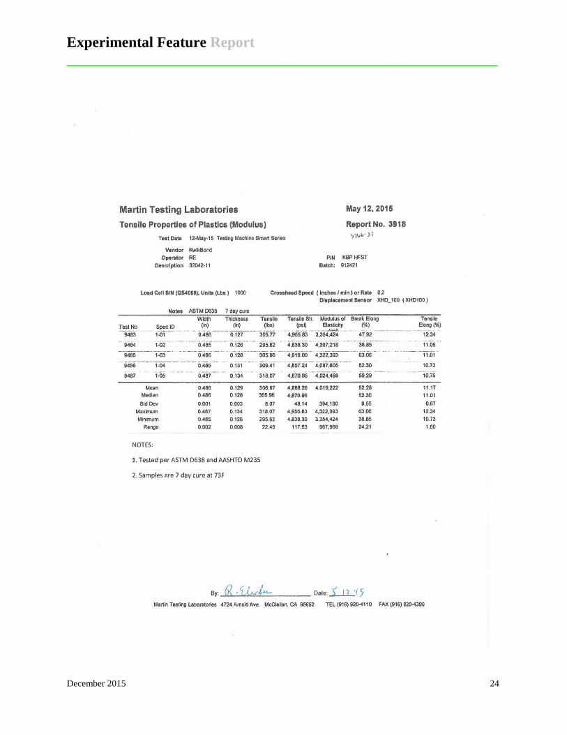
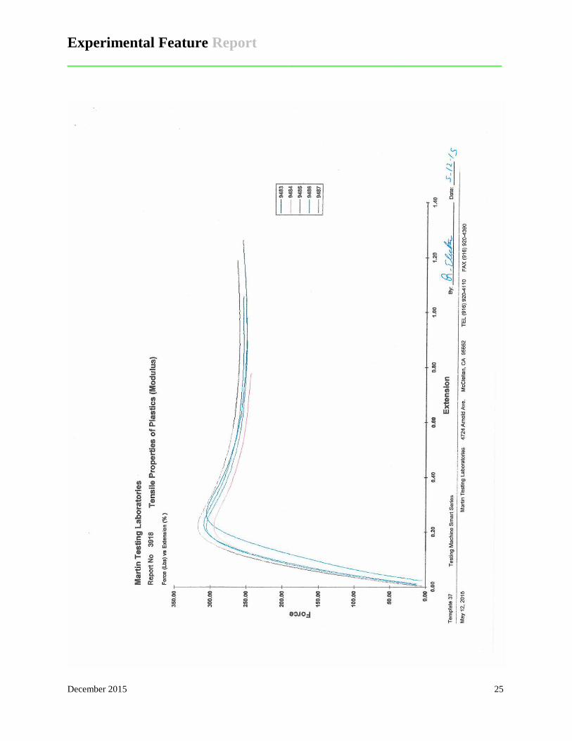
Table 1. Physical properties of Kwik Bond PPC™HFST. Test Specification Test Result
Viscosity 1,000 – 2,000 cps 1,390 cps Tensile Strength (ASTM D-638) 2,650 – 3,900 psi 4,888 psi Tensile Elongation at Break (ASTM D-638) >30% min 52% Compressive Strength (ASTM C-579) 5,000 psi at 24 hrs. 7,852 psi at 3 hrs.
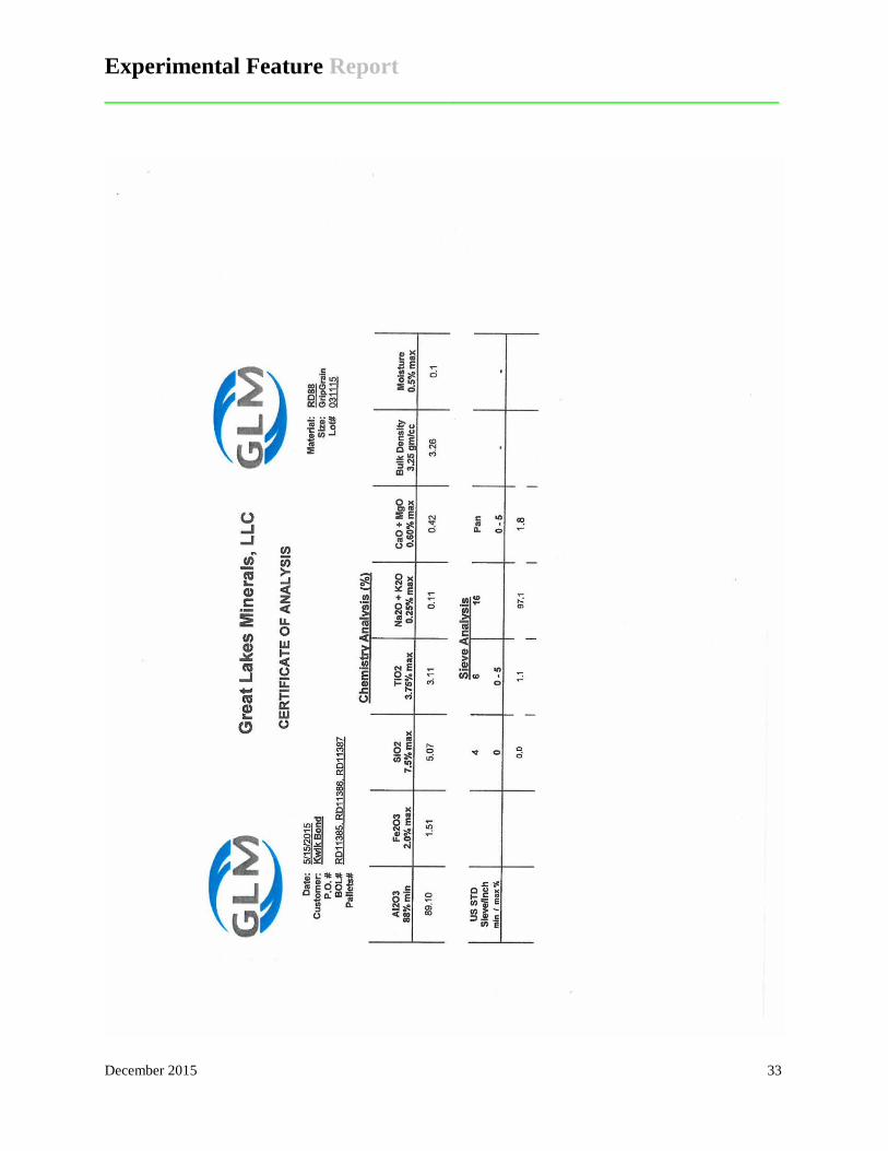
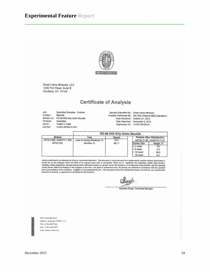
Bauxite is composed of aluminum oxide, silicon oxide, titanium oxide and iron oxide,
and is the source mineral for aluminum. Calcined bauxite is formed from a heating process that
removes the crystalline water. The heat transforms the bauxite rock from a hardness of between
1.0 and 3.0 on the Mohs scale to a hardness of 9.0 (Mohs scale of mineral hardness runs from
talc at 1.0 to diamond at 10.0, with 9.0 being corundum, Wikipedia). The physical properties of
calcined bauxite are listed in Table 2 (Bond Minerals, 2015).
Experimental Feature Report __________________________________________________________
December 2015 4
Table 2. Physical properties of calcined bauxite. Property Value
Particle Shape Angular Color Cream to Dark Grey Specific Gravity lb/ft3 3.70 Bulk Density lb/ft3 2.75 – 3.10 Hardness (Mohs scale) 9.0 Moisture Content 0.5 – 1.0% Polished Stone Value (1-3 mm) 70 minimum Aggregate Abrasion Value 10 maximum
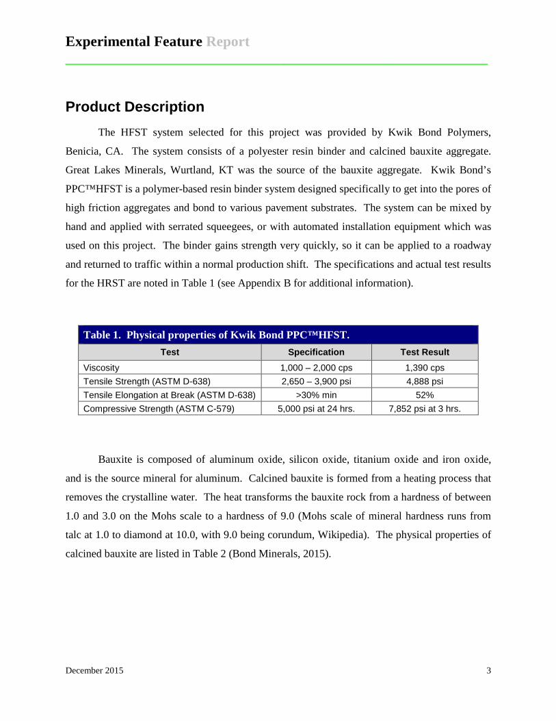
Construction Process The HFST was installed on the two ramps in the last two weeks of June, 2015. The
process is captured in a series of photographs. Figures 3-6 show the preparation prior to the
application of the HFST. The pavement receiving the HFST was cleaned to remove all dirt,
sand, oils and other debris using a combination of street sweepers and brooms. The paint stripes
were removed by diamond grinding if they were in the center of the roadway, or if they were the
edge stripes they were left in place or covered with duct tape. If the stripes were of the thermal
variety with raised lane marker bumps, duct tape was applied to prevent covering by the HFST.
Figure 3. Inlet covered prior to HFST. Figure 4. Lane line taped prior to HFST.
Experimental Feature Report __________________________________________________________
December 2015 5
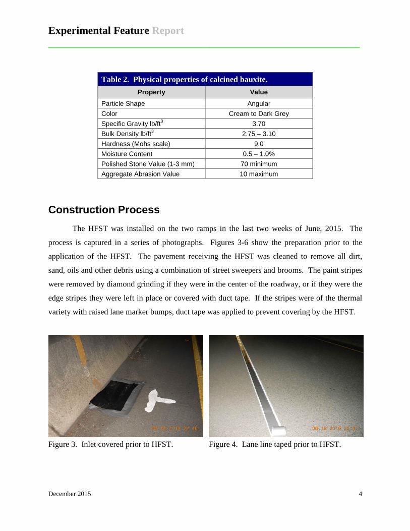
Figure 5. Taped expansion joint. Figure 6. Diamond grinding to remove
centerline stripe.
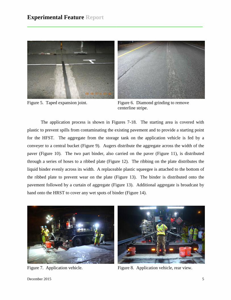
The application process is shown in Figures 7-18. The starting area is covered with
plastic to prevent spills from contaminating the existing pavement and to provide a starting point
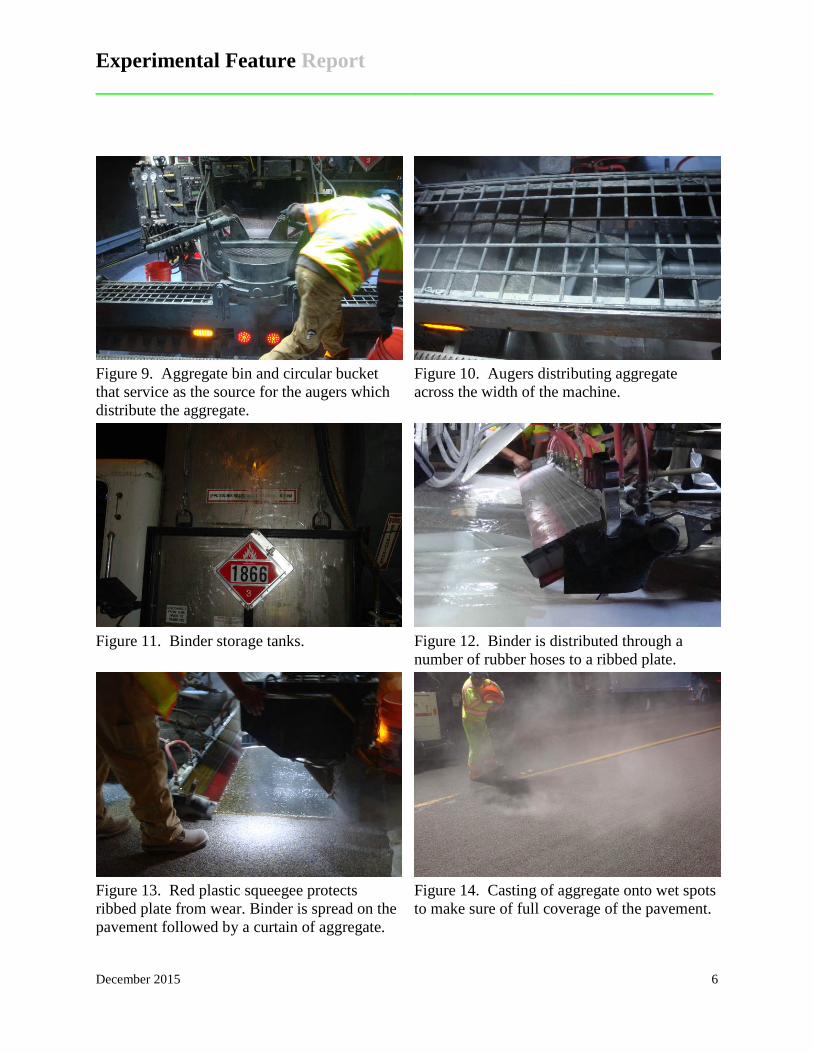
for the HFST. The aggregate from the storage tank on the application vehicle is fed by a
conveyer to a central bucket (Figure 9). Augers distribute the aggregate across the width of the
paver (Figure 10). The two part binder, also carried on the paver (Figure 11), is distributed
through a series of hoses to a ribbed plate (Figure 12). The ribbing on the plate distributes the
liquid binder evenly across its width. A replaceable plastic squeegee is attached to the bottom of
the ribbed plate to prevent wear on the plate (Figure 13). The binder is distributed onto the
pavement followed by a curtain of aggregate (Figure 13). Additional aggregate is broadcast by
hand onto the HRST to cover any wet spots of binder (Figure 14).
Figure 7. Application vehicle. Figure 8. Application vehicle, rear view.
Experimental Feature Report __________________________________________________________
December 2015 6
Figure 9. Aggregate bin and circular bucket that service as the source for the augers which distribute the aggregate.
Figure 10. Augers distributing aggregate across the width of the machine.
Figure 11. Binder storage tanks. Figure 12. Binder is distributed through a
number of rubber hoses to a ribbed plate.
Figure 13. Red plastic squeegee protects ribbed plate from wear. Binder is spread on the pavement followed by a curtain of aggregate.
Figure 14. Casting of aggregate onto wet spots to make sure of full coverage of the pavement.
Experimental Feature Report __________________________________________________________
December 2015 7
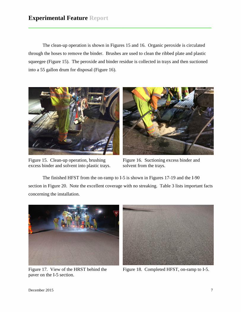
The clean-up operation is shown in Figures 15 and 16. Organic peroxide is circulated
through the hoses to remove the binder. Brushes are used to clean the ribbed plate and plastic
squeegee (Figure 15). The peroxide and binder residue is collected in trays and then suctioned
into a 55 gallon drum for disposal (Figure 16).
Figure 15. Clean-up operation, brushing excess binder and solvent into plastic trays.
Figure 16. Suctioning excess binder and solvent from the trays.
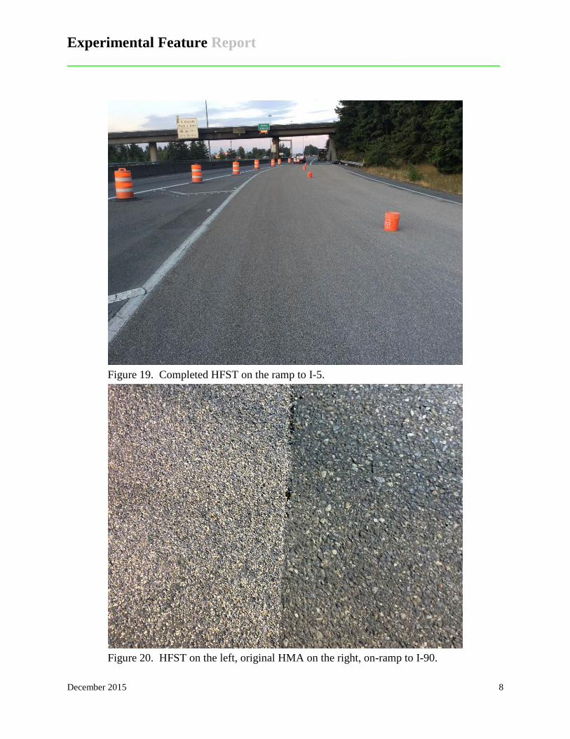
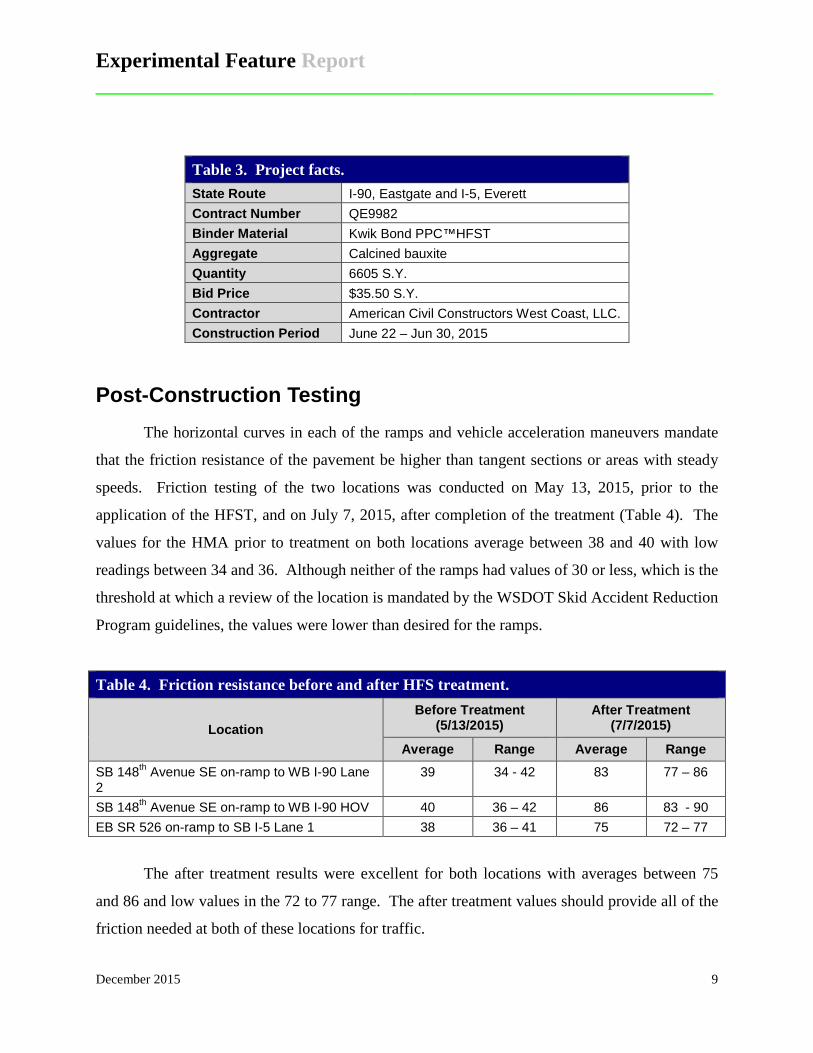
The finished HFST from the on-ramp to I-5 is shown in Figures 17-19 and the I-90
section in Figure 20. Note the excellent coverage with no streaking. Table 3 lists important facts
concerning the installation.
Figure 17. View of the HRST behind the paver on the I-5 section.
Figure 18. Completed HFST, on-ramp to I-5.
Experimental Feature Report __________________________________________________________
December 2015 8
Figure 19. Completed HFST on the ramp to I-5.
Figure 20. HFST on the left, original HMA on the right, on-ramp to I-90.
Experimental Feature Report __________________________________________________________
December 2015 9
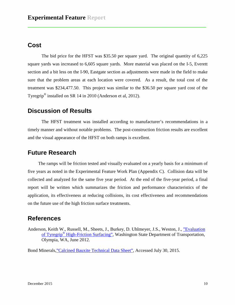
Table 3. Project facts. State Route I-90, Eastgate and I-5, Everett Contract Number QE9982 Binder Material Kwik Bond PPC™HFST Aggregate Calcined bauxite Quantity 6605 S.Y. Bid Price $35.50 S.Y. Contractor American Civil Constructors West Coast, LLC. Construction Period June 22 – Jun 30, 2015
Post-Construction Testing The horizontal curves in each of the ramps and vehicle acceleration maneuvers mandate
that the friction resistance of the pavement be higher than tangent sections or areas with steady
speeds. Friction testing of the two locations was conducted on May 13, 2015, prior to the
application of the HFST, and on July 7, 2015, after completion of the treatment (Table 4). The
values for the HMA prior to treatment on both locations average between 38 and 40 with low
readings between 34 and 36. Although neither of the ramps had values of 30 or less, which is the
threshold at which a review of the location is mandated by the WSDOT Skid Accident Reduction
Program guidelines, the values were lower than desired for the ramps.
Table 4. Friction resistance before and after HFS treatment.
Location Before Treatment
(5/13/2015) After Treatment
(7/7/2015)
Average Range Average Range SB 148th Avenue SE on-ramp to WB I-90 Lane 2
39 34 - 42 83 77 – 86
SB 148th Avenue SE on-ramp to WB I-90 HOV 40 36 – 42 86 83 - 90 EB SR 526 on-ramp to SB I-5 Lane 1 38 36 – 41 75 72 – 77
The after treatment results were excellent for both locations with averages between 75
and 86 and low values in the 72 to 77 range. The after treatment values should provide all of the
friction needed at both of these locations for traffic.
Experimental Feature Report __________________________________________________________
December 2015 10
Cost The bid price for the HFST was $35.50 per square yard. The original quantity of 6,225
square yards was increased to 6,605 square yards. More material was placed on the I-5, Everett
section and a bit less on the I-90, Eastgate section as adjustments were made in the field to make
sure that the problem areas at each location were covered. As a result, the total cost of the
treatment was $234,477.50. This project was similar to the $36.50 per square yard cost of the
Tyregrip® installed on SR 14 in 2010 (Anderson et al, 2012).
Discussion of Results The HFST treatment was installed according to manufacturer’s recommendations in a
timely manner and without notable problems. The post-construction friction results are excellent
and the visual appearance of the HFST on both ramps is excellent.
Future Research The ramps will be friction tested and visually evaluated on a yearly basis for a minimum of
five years as noted in the Experimental Feature Work Plan (Appendix C). Collision data will be
collected and analyzed for the same five year period. At the end of the five-year period, a final
report will be written which summarizes the friction and performance characteristics of the
application, its effectiveness at reducing collisions, its cost effectiveness and recommendations
on the future use of the high friction surface treatments.
References Anderson, Keith W., Russell, M., Sheets, J., Burkey, D. Uhlmeyer, J.S., Weston, J., ”Evaluation
of Tyregrip® High-Friction Surfacing”, Washington State Department of Transportation, Olympia, WA, June 2012.
Bond Minerals,”Calcined Bauxite Technical Data Sheet”, Accessed July 30, 2015.
Experimental Feature Report __________________________________________________________
December 2015 11
Appendix A Contract Special Provisions
Experimental Feature Report __________________________________________________________
December 2015 12
Division 5 Surface Treatments and Pavements
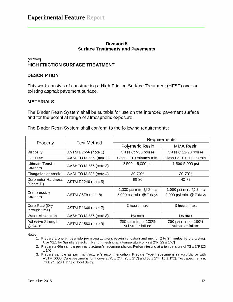
(******) HIGH FRICTION SURFACE TREATMENT DESCRIPTION This work consists of constructing a High Friction Surface Treatment (HFST) over an existing asphalt pavement surface. MATERIALS The Binder Resin System shall be suitable for use on the intended pavement surface and for the potential range of atmospheric exposure. The Binder Resin System shall conform to the following requirements:
Property Test Method Requirements
Polymeric Resin MMA Resin Viscosity ASTM D2556 (note 1) Class C:7-30 poises Class C 12-20 poises Gel Time AASHTO M 235 (note 2) Class C:10 minutes min. Class C: 10 minutes min. Ultimate Tensile Strength AASHTO M 235 (note 3) 2,500 – 5,000 psi 1,500-5,000 psi
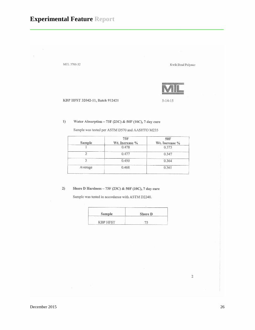
Elongation at break AASHTO M 235 (note 4) 30-70% 30-70% Durometer Hardness (Shore D) ASTM D2240 (note 5) 60-80 40-75
Compressive Strength ASTM C579 (note 6)
1,000 psi min. @ 3 hrs 5,000 psi min. @ 7 days
1,000 psi min. @ 3 hrs 2,000 psi min. @ 7 days
Cure Rate (Dry through time) ASTM D1640 (note 7) 3 hours max. 3 hours max.
Water Absorption AASHTO M 235 (note 8) 1% max. 1% max. Adhesive Strength @ 24 hr ASTM C1583 (note 9) 250 psi min. or 100%
substrate failure 250 psi min. or 100%
substrate failure Notes:
1. Prepare a one pint sample per manufacturer’s recommendation and mix for 2 to 3 minutes before testing. Use X1.1 for Spindle Selection. Perform testing at a temperature of 73 ± 2°F [23 ± 1°C].
2. Prepare a 60g sample per manufacturer’s recommendation. Perform testing at a temperature of 73 ± 2°F [23 ± 1°C].
3. Prepare sample as per manufacturer’s recommendation. Prepare Type I specimens in accordance with ASTM D638. Cure specimens for 7 days at 73 ± 2°F [23 ± 1°C] and 50 ± 2°F [10 ± 1°C]. Test specimens at 73 ± 2°F [23 ± 1°C] without delay.
Experimental Feature Report __________________________________________________________
December 2015 13
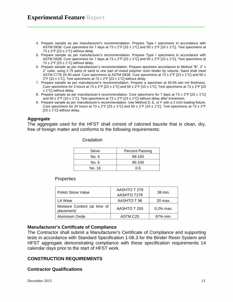
4. Prepare sample as per manufacturer’s recommendation. Prepare Type I specimens in accordance with ASTM D638. Cure specimens for 7 days at 73 ± 2°F [23 ± 1°C] and 50 ± 2°F [10 ± 1°C]. Test specimens at 73 ± 2°F [23 ± 1°C] without delay.
5. Prepare sample as per manufacturer’s recommendation. Prepare Type I specimens in accordance with ASTM D638. Cure specimens for 7 days at 73 ± 2°F [23 ± 1°C] and 50 ± 2°F [10 ± 1°C]. Test specimens at 73 ± 2°F [23 ± 1°C] without delay.
6. Prepare sample as per manufacturer’s recommendation. Prepare specimen accordance to Method “B”, 2” x 2” cube, using 2.75 parts of sand to one part of mixed polymer resin binder by volume. Sand shall meet ASTM C778 20-30 sand. Cure specimens at ASTM D638. Cure specimens at 73 ± 2°F [23 ± 1°C] and 50 ± 2°F [10 ± 1°C]. Test specimens at 73 ± 2°F [23 ± 1°C] without delay.
7. Prepare sample as per manufacturer’s recommendation. Prepare a specimen at 50-55 wet mil thickness. Cure specimens for 3 hours at 73 ± 2°F [23 ± 1°C] and 50 ± 2°F [10 ± 1°C]. Test specimens at 73 ± 2°F [23 ± 1°C] without delay.
8. Prepare sample as per manufacturer’s recommendation. Cure specimens for 7 days at 73 ± 2°F [23 ± 1°C] and 50 ± 2°F [10 ± 1°C]. Test specimens at 73 ± 2°F [23 ± 1°C] without delay after immersion.
9. Prepare sample as per manufacturer’s recommendation. Use Method D, E, or F with a 2 inch loading fixture. Cure specimens for 24 hours at 73 ± 2°F [23 ± 1°C] and 50 ± 2°F [10 ± 1°C]. Test specimens at 73 ± 2°F [23 ± 1°C] without delay.
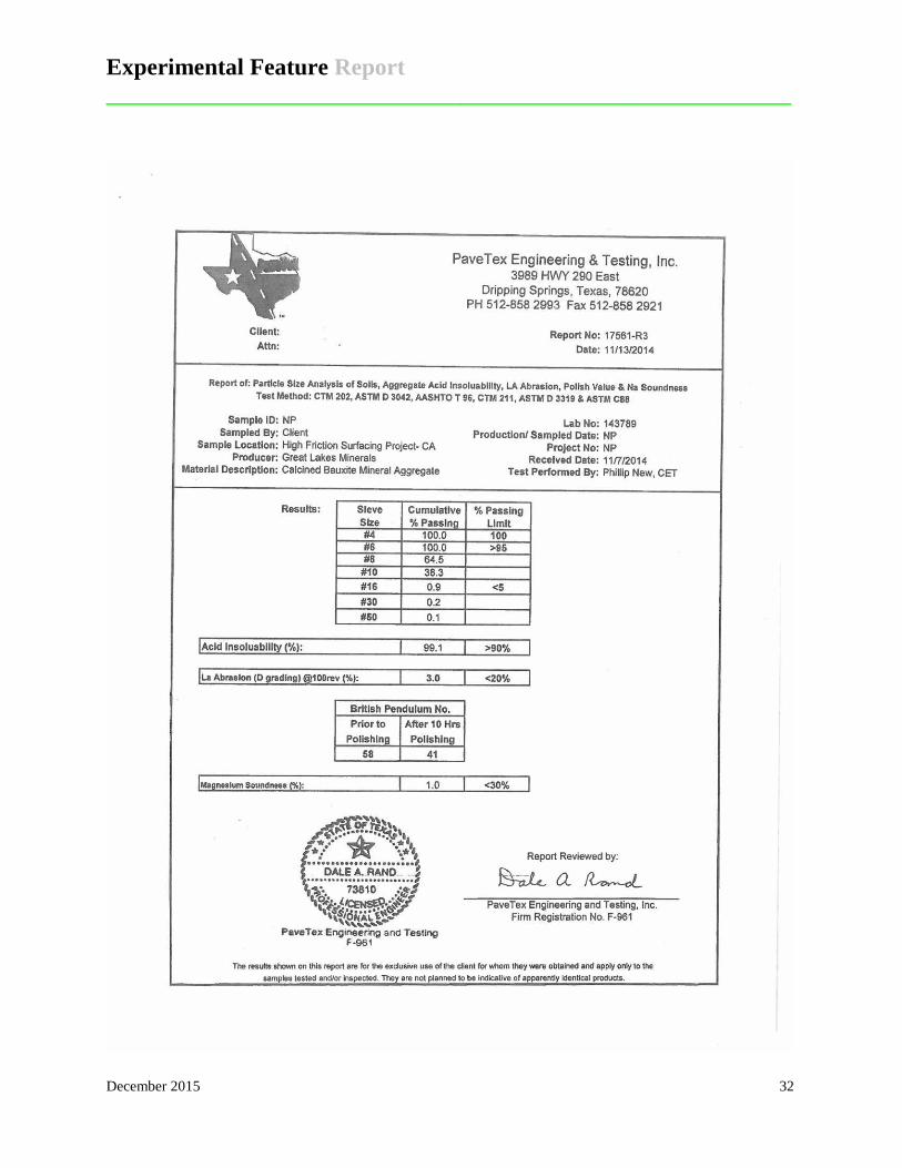
Aggregate The aggregate used for the HFST shall consist of calcined bauxite that is clean, dry, free of foreign matter and conforms to the following requirements: Gradation
Sieve Percent Passing No. 4 99-100 No. 6 95-100
No. 16 0-5
Properties
Polish Stone Value AASHTO T 279 AASHTO T278
38 min.
LA Wear AASHTO T 96 20 max. Moisture Content (at time of placement) AASHTO T 255 0.2% max.
Aluminum Oxide ASTM C25 87% min. Manufacturer’s Certificate of Compliance The Contractor shall submit a Manufacturer’s Certificate of Compliance and supporting tests in accordance with Standard Specification 1-06.3 for the Binder Resin System and HFST aggregate demonstrating compliance with these specification requirements 14 calendar days prior to the start of HFST work. CONSTRUCTION REQUIREMENTS Contractor Qualifications
Experimental Feature Report __________________________________________________________
December 2015 14
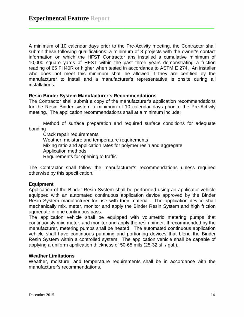
A minimum of 10 calendar days prior to the Pre-Activity meeting, the Contractor shall submit these following qualifications: a minimum of 3 projects with the owner’s contact information on which the HFST Contractor ahs installed a cumulative minimum of 10,000 square yards of HFST within the past three years demonstrating a friction reading of 65 FH40R or higher when tested in accordance to ASTM E 274. An installer who does not meet this minimum shall be allowed if they are certified by the manufacturer to install and a manufacturer’s representative is onsite during all installations. Resin Binder System Manufacturer’s Recommendations The Contractor shall submit a copy of the manufacturer’s application recommendations for the Resin Binder system a minimum of 10 calendar days prior to the Pre-Activity meeting. The application recommendations shall at a minimum include: Method of surface preparation and required surface conditions for adequate bonding Crack repair requirements
Weather, moisture and temperature requirements Mixing ratio and application rates for polymer resin and aggregate Application methods Requirements for opening to traffic
The Contractor shall follow the manufacturer’s recommendations unless required otherwise by this specification. Equipment Application of the Binder Resin System shall be performed using an applicator vehicle equipped with an automated continuous application device approved by the Binder Resin System manufacturer for use with their material. The application device shall mechanically mix, meter, monitor and apply the Binder Resin System and high friction aggregate in one continuous pass. The application vehicle shall be equipped with volumetric metering pumps that continuously mix, meter, and monitor and apply the resin binder. If recommended by the manufacturer, metering pumps shall be heated. The automated continuous application vehicle shall have continuous pumping and portioning devices that blend the Binder Resin System within a controlled system. The application vehicle shall be capable of applying a uniform application thickness of 50-65 mils (25-32 sf. / gal.). Weather Limitations Weather, moisture, and temperature requirements shall be in accordance with the manufacturer’s recommendations.
Experimental Feature Report __________________________________________________________
December 2015 15
HFST shall not be placed during weather and temperature condition with will not allow the Resin Binder System to adequately cure prior to the required time for opening to traffic. Surface Preparation Prior to placement of the HFST, the existing HOV diamond pavement markings and solid wide lane line on the Everett ramp shall be removed from pavement surfaces. Drainage structures, utility covers, and transverse expansion joints, within the enclosed surface area of HFST shall be covered or otherwise protected prior to HFST placement. The surface to receive the HFST shall be thoroughly clean, dry and free of all dust, oil, debris and deleterious other. Pavement surfaces contaminated with oils, greases, or other deleterious materials not removed by the surface preparation shall be washes with a detergent solution, rinsed with clean water, and dried using a hot compressed air lance. Clean asphalt pavement surfaces using mechanical sweepers and high pressure air wash with sufficient oil traps. Mechanically sweep all surfaces to remove dirt, loose aggregate, debris, and deleterious material. Vacuum sweep or air wash using a minimum of 180 cfm of clean and dry compressed air, all surfaces to remove all dust, debris, and deleterious material. Maintain the tip of the air lance within 12 inches of the surface. Cracks greater than 1/4 inch in width shall be filled with the mixed Binder Resin System. Prior to HFST application, the Engineer will mark all cracks that require treatment and will review these areas with the Contractor. Once the binder resin in the pre-treated areas has gelled, the installation may proceed. Application The Binder Resin System shall be mixed and placed onto the pavement using a Truck Mounted Application machine at a uniform application thickness of 50-65 mils (25-32 sf. /gal.). The Binder Resin System shall be blended and mixed within 2% of the ratio recommended by the manufacturer and shall be continuously applied once blended. The calcined bauxite aggregate shall be immediately applied using the same integrated application truck and at a uniform rate of 12-15 lbs. per square yard. The aggregate shall completely cover the Binder Resin System to achieve a uniform surface with no exposed resin binder visible on the surface. It is the responsibility of the HFST installer to ensure full embedment of the calcined bauxite aggregate. Irregular areas or areas inaccessible to truck mounted application machine may be placed by hand methods in accordance with the Binder Resin system manufacturer’s recommendations. Wet spots must be covered with the aggregate prior to the gelling of the Binder Resin System.
Experimental Feature Report __________________________________________________________
December 2015 16
Equipment and traffic shall not be allowed on the HFST until curing is complete. Opening to Traffic Prior to opening to traffic the roadway shall be swept clean with loose aggregate removed and disposed of in accordance with Section 2-03.3(7) C. As shown in the plans, all existing pavement markings either immediately adjacent to, or within the treated lanes, shall be reinstalled after placement of HSFT and roadway sweeping. All HFST areas, as well as untreated shoulders adjacent to the HFST, shall be re-swept three to five days after the initial installation is completed. Application of HFST The finished HFST surface shall have a uniform coverage of aggregate without streaks or areas of exposed polymer resin binder. After completion of the HFST, the Contractor shall notify the Project Engineer that the HFST is ready for testing. WSDOT State Materials Lab will perform the testing. Conditions permitting: testing will be completed within 30 calendar days of notification. No testing will be done unless the roadway surface temperatures is a minimum of 40°F and rising, and the requirements of ASTM E 274 are satisfied. The completed HFST shall attain an average friction number (FH40R) of 65 or greater when tested in accordance with ASTM E 274 with no individual test less than a friction number (FH40R) of 60. The average friction number will be based on a minimum of five tests points in each lane. The Engineer may isolate areas of exposed resin binder, insufficient aggregate of that otherwise appear defective for additional testing. These areas shall attain a friction number (FN40R) of 60 or greater. If the HFST fails to meet the requirements of this section, the contractor shall remove and replace the defective areas at the Contractor’s expense. The areas selected for reinstallation will be retested using the same methods and subject to the acceptance criteria as outlined above. Measurement High friction surface treatment shall be measured by the square yard. No deduction will be made for drainage structures or utility appurtenances within the HFST placement area. Payment
Experimental Feature Report __________________________________________________________
December 2015 17
“High Friction Surface Treatment”, per square yard. The area to be paid for will be based on the dimensions shown on the plans. No additional payment will be made for reinstallation of HFST where the initial installation was determined to be defective. The contract price paid per square yard for high friction surface treatment (HFST) shall include full compensation for furnishing all labor, materials, tools, equipment, and incidentals and for doing all the work involved in HFST, complete in place, including the submittals, surface preparation, roadway sweeping, and other work, all in accordance with the attached Contract Plans, these Contract Provisions, the Standard Specifications, and as directed by the Engineer.
Experimental Feature Report __________________________________________________________
December 2015 18
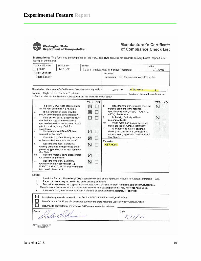
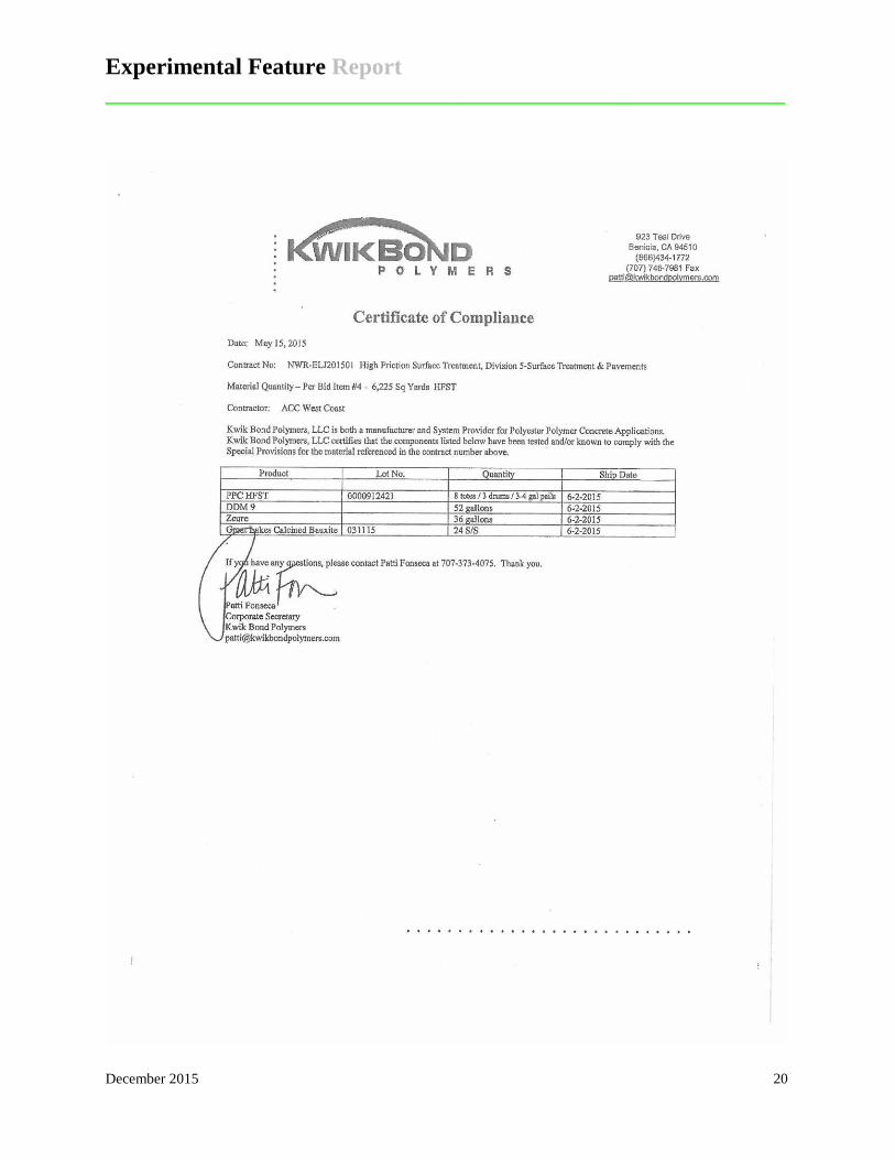
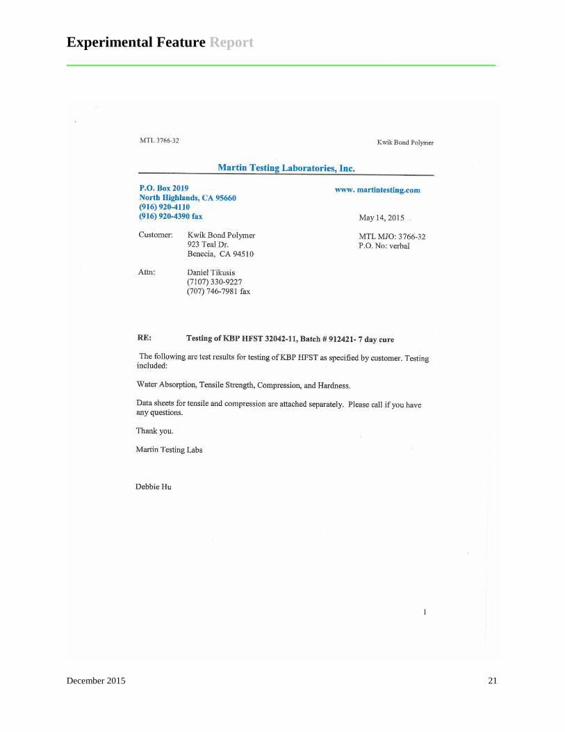
Appendix B Manufacturer’s Certificate of Compliance
Experimental Feature Report __________________________________________________________
December 2015 19
Experimental Feature Report __________________________________________________________
December 2015 20
Experimental Feature Report __________________________________________________________
December 2015 21
Experimental Feature Report __________________________________________________________
December 2015 22
Experimental Feature Report __________________________________________________________
December 2015 23
Experimental Feature Report __________________________________________________________
December 2015 24
Experimental Feature Report __________________________________________________________
December 2015 25
Experimental Feature Report __________________________________________________________
December 2015 26
Experimental Feature Report __________________________________________________________
December 2015 27
Experimental Feature Report __________________________________________________________
December 2015 28
Experimental Feature Report __________________________________________________________
December 2015 29
Experimental Feature Report __________________________________________________________
December 2015 30
Experimental Feature Report __________________________________________________________
December 2015 31
Experimental Feature Report __________________________________________________________
December 2015 32
Experimental Feature Report __________________________________________________________
December 2015 33
Experimental Feature Report __________________________________________________________
December 2015 34

Experimental Feature Report __________________________________________________________
December 2015 35
Appendix C Work Plan
Experimental Feature Report __________________________________________________________
December 2015 36
Washington State Department of Transportation
WORK PLAN
High Friction Surface Treatment
QE9982 Interstate 90
SB 148th Avenue SE on-ramp to I-90 Westbound I-5
SR 526 Eastbound on-ramp to I-5 Southbound
Keith W. Anderson Experimental Features Engineer
Washington State Department of Transportation
Experimental Feature Report __________________________________________________________
December 2015 37
Introduction Two ramps, one on I-90 and one on I-5, will have a High Friction Surface (HFS) applied
to the ramps to improve the frictional properties of the pavement. The I-90 section is the on-
ramp from 148th Avenue SE to westbound I-90 in Eastgate (Figure 1). The I-5 section is the on-
ramp from SR 526 eastbound to I-5 southbound south of Everett (Figure 2). Both on-ramps are
high accident locations. WSDOT installed warning signs to alert motorists to the hazard but
there is still a high occurrence of accidents. The ramp geometry and type of accidents indicate
that increasing the pavement friction may reduce the number of accidents.
There are several methods to increase friction on an existing pavement. These include
replacing the pavement, placing a surface treatment such as a chip seal over the existing
pavement or grooving the pavement by diamond grinding (PCC pavements). These methods are
costly and the existing HMA pavement on the subject ramps is not due for rehabilitation. A less
costly solution is to install a thin high-friction laminate surface over the existing pavement.
The HFS system selected for this project was provided by Kwik Bond Polymers, Benicia,
CA. The system consists of a polyester resin binder and calcined bauxite aggregate. Great
Lakes Minerals, Wurtland, KT was the source of the bauxite aggregate. The system can be
applied by machine or by hand depending on the size of the project.
Scope Kwik Bond HFS will be installed on the curved portions of the two ramps. The amount
of HFS to be installed is 6,225 square yards, 1520 ft. by 24 ft. on SR 526 and 1055 ft. by 16 ft.
on 148th Avenue SE. The contract special provisions require that the method of application be
by a mechanical device that mixes, monitors and applies the binder resin system and high friction
aggregate in one continuous pass.
Experimental Feature Report __________________________________________________________
December 2015 38
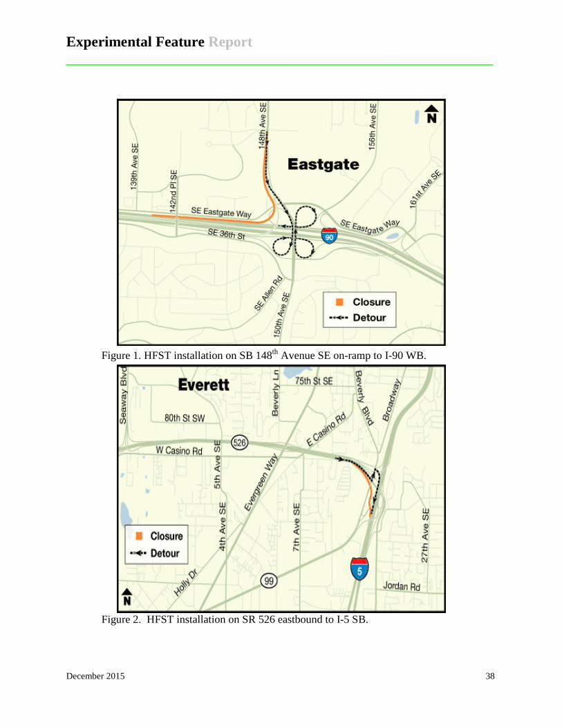
Figure 1. HFST installation on SB 148th Avenue SE on-ramp to I-90 WB.
Figure 2. HFST installation on SR 526 eastbound to I-5 SB.
Experimental Feature Report __________________________________________________________
December 2015 39
Staffing This installation will be constructed as a Northwest Region Traffic Office low cost
enhancement project. Representatives from and WSDOT Materials Laboratory (1 – 2 people)
will be involved in monitoring the installation to collect data and photos for the post-construction
report.
Contacts and Report Author Mark Russell State Pavement Design Engineer Washington State DOT (360) 709-5479 [email protected] Keith Anderson Experimental Features Engineer Washington State DOT (360) 584-8648 [email protected]
Testing Pavement performance will be monitored by the following methods:
• Friction will be measured before and after construction then annually.
• Accident data will be gathered by the Northwest Region Traffic Office
• Visual inspections will be conducted to collect data on cracking, delaminations (potholes) and other pavement distress.
Reporting A “Post Construction Report” will be written following completion of the ramps. This
report will include construction details, cost of the treatment, construction test results, and other
details concerning the overall process. Friction testing will be conducted annually and any
problems with the friction values or condition of the HFS reported to the NWR. At the end of
the five-year period, a final report will be written which summarizes the performance
Experimental Feature Report __________________________________________________________
December 2015 40
characteristics, effectiveness at reducing accidents and future recommendations for use of this
process.
Cost Estimate Construction Costs
No additional construction costs are required. This project will be constructed as a Region
HAL enhancement (QE program) project.
Testing Costs Pre and post-construction friction testing will be conducted as part of the Region Q
program project (estimated cost $2,500). Annual friction testing will be conducted in
conjunction with the annual post-construction testing of HMA preservation projects.
Annual inspections will be conducted to assess the condition of the HFS at a cost of
approximately $3,000.
Report Writing Costs Initial Report – 16 hours = $2,112
Final Report – 32 hours = $4,224
Total Cost = $9,336
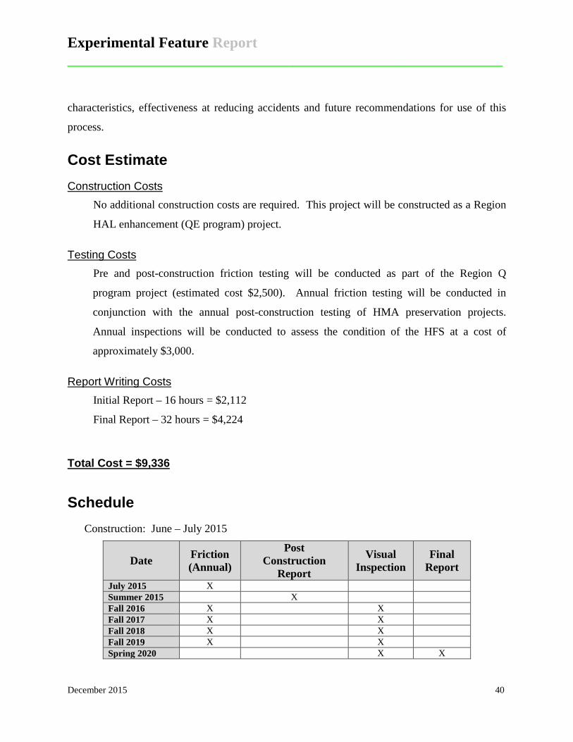
Schedule Construction: June – July 2015
Date Friction (Annual)
Post Construction
Report
Visual Inspection
Final Report
July 2015 X Summer 2015 X Fall 2016 X X Fall 2017 X X Fall 2018 X X Fall 2019 X X Spring 2020 X X