korado convectors catalogue - hydronic heating systems · 78 [korawall developed for low...
TRANSCRIPT


47
O P T I M I Z E D
C O N V E C T I O N
Products equipped with forced convection to increase
effi ciency in heating, cooling and dry-cooling
78
KORAWALL [
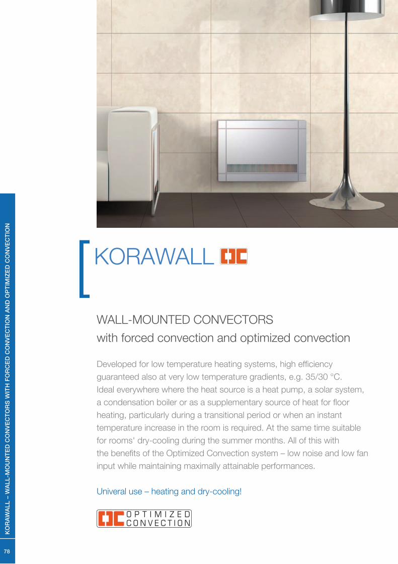
Developed for low temperature heating systems, high effi ciency
guaranteed also at very low temperature gradients, e.g. 35/30 °C.
Ideal everywhere where the heat source is a heat pump, a solar system,
a condensation boiler or as a supplementary source of heat for fl oor
heating, particularly during a transitional period or when an instant
temperature increase in the room is required. At the same time suitable
for rooms' dry-cooling during the summer months. All of this with
the benefi ts of the Optimized Convection system – low noise and low fan
input while maintaining maximally attainable performances.
Univeral use – heating and dry-cooling!
WALL-MOUNTED CONVECTORS
with forced convection and optimized convection
KO
RA
WA
LL
– W
AL
L-M
OU
NT
ED
CO
NV
EC
TO
RS
WIT
H F
OR
CE
D C
ON
VE
CT
ION
AN
D O
PT
IMIZ
ED
CO
NV
EC
TIO
N
79
• used for heating or dry-cooling
• high efficiency even at low temperatures of the heating system
• patented design solutions
• high-perfomance, low energy and quiet fans
• the same regulation as the one for floor convectors
KORAFLEX FV and free standing convectors with forced
convection KORALINE LV
• two-pipe system
• right bottom connection
• controls possible through BMS (Building Managing System)
• the convectors is intended for dry environment
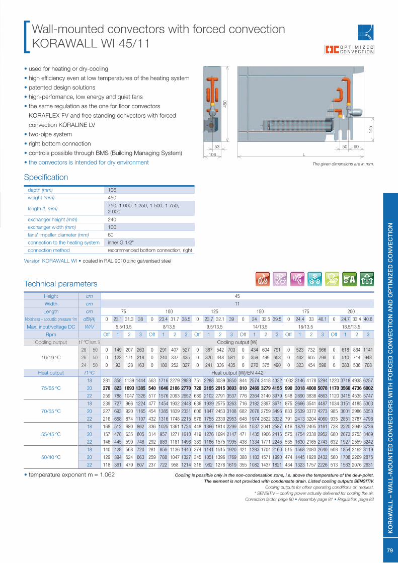
Wall-mounted convectors with forced convection
KORAWALL WI 45/11
depth (mm) 106
weight (mm) 450
length (L mm)750, 1 000, 1 250, 1 500, 1 750,
2 000
exchanger height (mm) 240
exchanger width (mm) 100
fans' impeller diameter (mm) 60
connection to the heating system inner G 1/2"
connection method recommended bottom connection, right
Specifi cation
The given dimensions are in mm.
14
5
45
0
106
53
Technical parameters
• temperature exponent m = 1.062 Cooling is possible only in the non-condensation zone, i.e. above the temperature of the dew-point.
The element is not provided with condensate drain. Listed cooling outputs SENSITIV.
Cooling outputs for other operating conditions on request.
* SENSITIV – cooling power actually delivered for cooling the air.
Correction factor page 80 • Assembly page 81 • Regulation page 82
Height cm 45
Width cm 11
Length cm 75 100 125 150 175 200
Noisiness – acoustic pressure 1m dB(A) 0 23.1 31.3 38 0 23.4 31.7 38.5 0 23.7 32.1 39 0 24 32.5 39.5 0 24.4 33 40.1 0 24.7 33.4 40.6
Max. input/voltage DC W/V 5.5/13.5 8/13.5 9.5/13.5 14/13.5 16/13.5 18.5/13.5
Rpm Off 1 2 3 Off 1 2 3 Off 1 2 3 Off 1 2 3 Off 1 2 3 Off 1 2 3
Cooling output t1 ºC hum. % Cooling output [W]
16/19 ºC
28 50 0 149 207 263 0 291 407 527 0 387 542 703 0 434 604 791 0 523 732 966 0 618 864 1141
26 50 0 123 171 218 0 240 337 435 0 320 448 581 0 359 499 653 0 432 605 798 0 510 714 943
24 50 0 93 128 163 0 180 252 327 0 241 336 435 0 270 375 490 0 323 454 598 0 383 536 708
Heat output t1 ºC Heat output [W]/EN 442
75/65 ºC
18 281 858 1139 1444 563 1716 2279 2888 751 2288 3039 3850 844 2574 3418 4332 1032 3146 4178 5294 1220 3718 4938 6257
20 270 823 1093 1385 540 1646 2186 2770 720 2195 2915 3693 810 2469 3279 4155 990 3018 4008 5078 1170 3566 4736 6002
22 259 788 1047 1326 517 1576 2093 2652 689 2102 2791 3537 776 2364 3140 3979 948 2890 3838 4863 1120 3415 4535 5747
70/55 ºC
18 239 727 966 1224 477 1454 1932 2448 636 1939 2575 3263 716 2182 2897 3671 875 2666 3541 4487 1034 3151 4185 5303
20 227 693 920 1165 454 1385 1839 2331 606 1847 2453 3108 682 2078 2759 3496 833 2539 3372 4273 985 3001 3986 5050
22 216 658 874 1107 432 1316 1748 2215 576 1755 2330 2953 648 1974 2622 3322 791 2413 3204 4060 935 2851 3787 4798
55/45 ºC
18 168 512 680 862 336 1025 1361 1724 448 1366 1814 2299 504 1537 2041 2587 616 1879 2495 3161 728 2220 2949 3736
20 157 478 635 805 314 957 1271 1610 419 1276 1694 2147 471 1435 1906 2415 575 1754 2330 2952 680 2073 2753 3489
22 146 445 590 748 292 889 1181 1496 389 1186 1575 1995 438 1334 1771 2245 535 1630 2165 2743 632 1927 2559 3242
50/40 ºC
18 140 428 568 720 281 856 1136 1440 374 1141 1515 1920 421 1283 1704 2160 515 1568 2083 2640 608 1854 2462 3119
20 129 394 524 663 259 788 1047 1327 345 1051 1396 1769 388 1183 1571 1990 474 1445 1920 2432 560 1708 2269 2875
22 118 361 479 607 237 722 958 1214 316 962 1278 1619 355 1082 1437 1821 434 1323 1757 2226 513 1563 2076 2631
50 90
L
KO
RA
WA
LL
– W
AL
L-M
OU
NT
ED
CO
NV
EC
TO
RS
WIT
H F
OR
CE
D C
ON
VE
CT
ION
AN
D O
PT
IMIZ
ED
CO
NV
EC
TIO
N
Version KORAWALL WI • coated in RAL 9010 zinc galvanised steel

80
Correction factor kt for a variant temperature difference ∆t (K)
∆t (K) 18 19 20 21 22 23 24 25 26 27 28 29 30 31 32 33
kt 0.338 0.358 0.378 0.398 0.418 0.438 0.459 0.479 0.499 0.520 0.540 0.561 0.581 0.602 0.623 0.643
∆t (K) 34 35 36 37 38 39 40 41 42 43 44 45 46 47 48 49
kt 0.664 0.685 0.705 0.726 0.747 0.768 0.789 0.810 0.831 0.852 0.873 0.894 0.915 0.936 0.958 0.979
∆t (K) 50 51 52 53 54 55 56 57 58 59 60
kt 1.000 1.021 1.043 1.064 1.085 1.107 1.128 1.149 1.171 1.192 1.214
KORAWALL WI 45/11
• temperature exponent m = 1.062
Weights and water volumes
of the wall-mounted radiator KORAWALL WI
Type 45/11
kg/linear meter 18.2
l/1 linear meter 1.4
The listed weights are without a packaging.
The contents of supplies and selectable specifi cations
Standard delivery contains• sheathing of zinc galvanised steel coated in shade
RAL 9010 – white
• AI/Cu heat exchanger with low water content, air vent
and uniquely shaped lamellas for a higher heat output
• group of low-energy fans
• connecting terminal (F Box)
• wall-mounting brackets
• mounting instructions
• the set is packed in a cardboard packaging
Optional accessories• in case of ordering more than 5 units it is possible to select
another sheathing colour shade (the manufacturer must be
consulted)
• shut off valve, thermostatic valve and thermoelectric drive
Note
• Standard supply does not include the regulation
• The regulation must be ordered separately in accordance with
the technical parameters
• Electrical regulation and regulation elements, see page 82
• Regulation is identical for all OC convectors
KO
RA
WA
LL
– W
AL
L-M
OU
NT
ED
CO
NV
EC
TO
RS
WIT
H F
OR
CE
D C
ON
VE
CT
ION
AN
D O
PT
IMIZ
ED
CO
NV
EC
TIO
N
81
Assembly electrical part• Regulation is identical with OC convectors
• We recommend to fit KORAWALL WI with the thermoelectric
drive
• Do not forget to provide power supply near the installation –
more details in the electrical assembly part on page 82 or in the
installation instructions
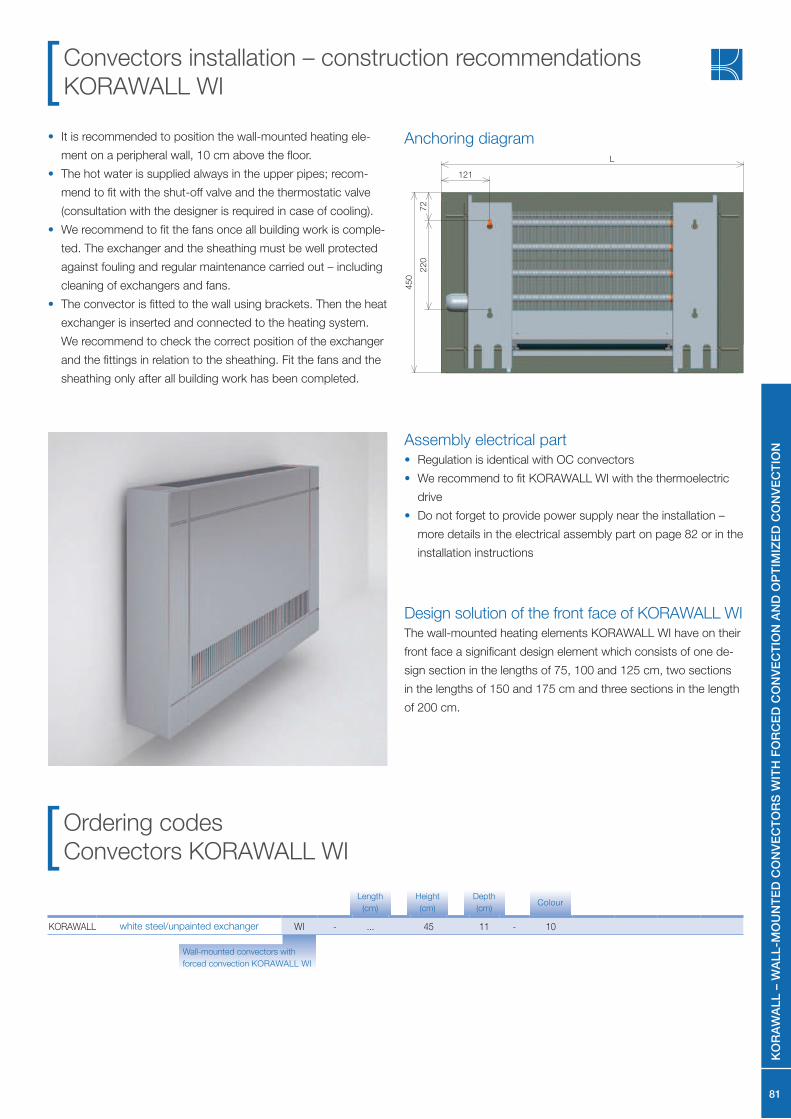
Anchoring diagram
Ordering codes
Convectors KORAWALL WI
• It is recommended to position the wall-mounted heating ele-
ment on a peripheral wall, 10 cm above the floor.
• The hot water is supplied always in the upper pipes; recom-
mend to fit with the shut-off valve and the thermostatic valve
(consultation with the designer is required in case of cooling).
• We recommend to fit the fans once all building work is comple-
ted. The exchanger and the sheathing must be well protected
against fouling and regular maintenance carried out – including
cleaning of exchangers and fans.
• The convector is fitted to the wall using brackets. Then the heat
exchanger is inserted and connected to the heating system.
We recommend to check the correct position of the exchanger
and the fittings in relation to the sheathing. Fit the fans and the
sheathing only after all building work has been completed.
Convectors installation – construction recommendations
KORAWALL WI
121
72
45
0
22
0
L
Design solution of the front face of KORAWALL WI The wall-mounted heating elements KORAWALL WI have on their
front face a significant design element which consists of one de-
sign section in the lengths of 75, 100 and 125 cm, two sections
in the lengths of 150 and 175 cm and three sections in the length
of 200 cm.
KO
RA
WA
LL
– W
AL
L-M
OU
NT
ED
CO
NV
EC
TO
RS
WIT
H F
OR
CE
D C
ON
VE
CT
ION
AN
D O
PT
IMIZ
ED
CO
NV
EC
TIO
N
KORAWALL white steel/unpainted exchanger WI - ... 45 11 - 10
Wall-mounted convectors with
forced convection KORAWALL WI
ColourLength
(cm)
Height
(cm)
Depth
(cm)

82
Regulation and acoustics[
EL
EC
TR
ICA
L R
EG
UL
AT
ION
OF
CO
NV
EC
TO
RS
83
Description of electrical regulation of convectors
Description of electrical regulation
of KORAFLEX FV, FV InPool, FI, FW,
KORALINE LV and KORAWALL WI
(hereinafter referred to as fan-coils)
Standard regulation:The regulation is designed for the control of the heating and cool-
ing output of convectors with blow fans. The standard part of the
fans is:
• Group of fans with a unique disk type synchronous engine
with permanent magnets. It is characterized mainly by very low
power consumption – the power input of the engine at the full
range of speed does not exceed 7.5 watts; the engine also runs
very quietly.
• Connecting terminal (F Box)
• Exchanger temperature sensor (switch)
Optional accessories The DC power supply source in accordance with the total power
input of the controlled fan-coil units. The offer includes 2 sizes, 60
W and 100 W. The power supply sources are supplied separately
for installation in the electrical switchboard on DIN rail.
• R-Box, containing the speed signal galvanic separation module,
controlling the fan speed and which also allows the selection
and optimization of various degrees of speed. The R-Box
is designed for mounting on DIN rail in the switchboard
• Plastic box for the placement of the DC power supply and the
R-Box for installations where the switchboard is too far
• Siemens thermostats
• Valves, thermoelectric drive 12 V DC
The performance is controlled by the working media On/Off
switching valve, if used, and by switching the On/Off the three
speed blower fan. When using a Siemens thermostat RDG100T
the speed is controlled automatically. All three speeds of the fan
can be smoothly adjusted. The fan speed is given by the size of
the voltage control signal CNTRL from the galvanic separation
signal module (R-Box). Detailed description of functions
and settings is available in the installation instructions supplied
with the product.
Fans are normally blocked by a temperature switch (TS1) at
a switching temperature of about 35 °C. This function may be
disconnected. This accessory is not supplied for KORAWALL
WI. For fan coils with dry-cooling effect it is still necessary to use
one cooling medium thermal switch (TS2) connected in parallel to
the temperature switch which activates at a temperature below
13 °C. The temperature and speed is controlled by Siemens
Thermostats RAB11, RDF600/IR or RDG 100T. Contact fields of
these thermostats (TS1) are connected to mains voltage, and that
is why it is necessary to use the R-Box signals' galvanic separa-
tion (the galvanic separation of signals is implemented by using
optocouplers).
The thermostat switches the DC power supply source of the
output voltage of approx. 13.5 V. Once the power supply source
is switched on the heating medium valves (if used) start opening.
Furthermore, the thermostat through galvanic separation module
generates the control voltage signal CNTRL. The control voltage
signal is of three levels, with each speed level smootly adjust-
able. The convectors control can be also carried out using a BMS
(Bulding Management System) higher-level output elements. One
BMS relay output controls the valve's opening/closing, and the
second continuous 0–10 V output controls the speed. The stand-
ard regulation enables the use of a themoelectric drive 12 V DC
that closes or opens the heating media valve. The function is set
in such a way that if heating is required, i.e. after the thermostat
switches on, the power supply is activated. The voltage from the
power supply source directly supplies the thermoelectric drives of
the valve for the control of the heating media inlet to the fan-coil
unit. If the heating output is not sufficient without the fan, it is pos-
sible to select the required speed of the fan (I. II. III.) with a switch.
Description of regulation of KORAFLEX FV InPool The above described system of regulation applies to pool applica-
tions for which this product is intended. The principle is the same
but the electrical equipment of the convectors differs the elec-
tronics of the motor, F box are located in a plastic box with high
degree of protection IP 67 which is placed inside the convectors.
When installing the connecting cables to the terminal block of the
F box must be connected as per instructions. In terms of tem-
perature and speed regulation the same types and variations of
thermostats are used with a restriction that the thermostats must
not be placed in the pool area. For these purposes we recom-
mend using the temperature sensor which senses the tempera-
ture in the pool area, see Accessories. The sensor is designed for
thermostats RDF 600 and RDG 100T.
The convectors is not designed for continuous flooding by pool
water. Get thoroughly familiar with the warranty and operating
conditions.
Installation must be performed according to valid standards
and safety regulations! The manufacturer is not liable for defects
or damage caused by improper installation.
EL
EC
TR
ICA
L R
EG
UL
AT
ION
OF
CO
NV
EC
TO
RS
84
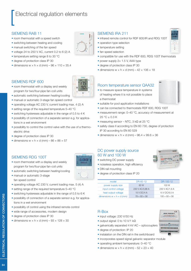
SIEMENS RDG 100T• room thermostat with a display and weekly
program for two/four-pipe fan-coil units
• automatic switching between heating/cooling
• manual or automatic 3-stage
fan speed control
• operating voltage AC 230 V, current loading max. 5 (4) A
• setting range of the required temperature 5–40 °C
• switching hystereses adjustable in the range of 0.5 to 6 K
• possibility of connection of a separate sensor e.g. for applica-
tions in a wet environment
• possibility of control using the infrared remote control
• wide range of accessories, modern design
• degree of protection class IP 30
• dimensions w × h × d (mm) – 93 × 128 × 30
SIEMENS IRA 211• infrared remote control for RDF 600/IR and RDG 100T
• operation type selection
• temperature setting
• fan speed selection
• compatible for use with the RDF 600, RDG 100T thermostats
• power supply 2× 1.5 V, AAA type
• degree of protection class IP 30
• dimensions w × h × d (mm) – 42 × 106 × 18
DC power supply source
60 W and 100 W• switching DC power supply
• noiseless operation, high efficiency
• DIN rail mounting
• degree of protection class IP 20
model DR-60-12 DR-100-12
power supply size 60 W 100 W
input control voltage 230 V AC/0,88 A 230 V AC/1,6 A
heat output voltage 15 V DC/4 A 15 V DC/6.5 A
dimensions w × h × d (mm) 78 × 93 × 56 100 × 93 × 56
SIEMENS RAB 11• room thermostat with a speed switch
• switching between heating and cooling
• manual switching of the fan speed
• voltage 24 to 250 V AC, current 0.2 to 6 (2) A
• temperature setting range 8 to 30 °C
• degree of protection class IP 30
• dimensions w × h × d (mm) – 96 × 110 × 35.4
SIEMENS RDF 600• room thermostat with a display and weekly
program for two/four-pipe fan-coil units
• automatic switching between heating/cooling
• manual or automatic 3-stage fan speed control
• operating voltage AC 230 V, current loading max. 4 (2) A
• setting range of the required temperature 5–40 °C
• switching hystereses adjustable in the range of 0.5 to 4 K
• possibility of connection of a separate sensor e.g. for applica-
tions in a wet environment
• possibility to control the control valve with the use of a thermo-
electric drive
• degree of protection class IP 30
• dimensions w × h × d (mm) – 86 × 86 × 57
Room temperature sensor QAA32• to measure space temperature in systems
of heating where it is not possible to place
a thermostat
• suitable for pool application installations
• can be connected to thermostats RDF 600, RDG 100T
• measurement range: 0–40 °C, accuracy of measurement at
25 °C ± 0.3 K
• measuring sensor – NTC, 3 kΩ at 25 °C
• safety class II according to EN 60 730, degree of protection
IP 30 according to EN 60 529
• dimensions w × h × d (mm) – 96.4 × 99.6 × 36
R-Box• input voltage: 230 V/50 Hz
• output signal: 0 to 10 V/1 kΩ
• galvanically separated 4 kV AC – optocouplers
• degree of protection: IP 20
• instalation on the DIN rail in the switchboard
• incorporates speed signal galvanic separator module
• operating ambient termperature: 0–40 °C
• dimensions w × h × d (mm) – 52 × 23 × 40
Electrical regulation elements
EL
EC
TR
ICA
L R
EG
UL
AT
ION
OF
CO
NV
EC
TO
RS

85
Shut-off valve• straight or corner section
(according to the order)
• dimension 1/2" G
• material – nickel-plated brass
Preset stage 1 2 3 4 5 6 7 8 9
speed 1 1/4 1 1/2 1 3/4 2 2 1/2 3 3 1/2 4Complete
opening
Kv 0.14 0.20 0.31 0.43 0.60 0.79 1.00 1.20 1.35
Kv fl ow coeffi cient (m3/h)
Heating control elements
(cooling) medium
Thermostatic head
fl uid with capillary• regulation range +6.5 to +28 °C
• installation of the actuator into the wall
• length of capilary 5 m
• hysteresis: ≤ 0.6 °C
Thermoelectric drive• power supply voltage:
12 V DC/150 m A/1.8 W
• CLOSED without power supply
• degree of protection: IP 54
• connection cable 2× 0.75 mm2, length 1 m
• closing/opening time < 3 min.
Thermostatic valve• straight or corner section (according to the order)
• with preset Kv value
• dimension 1/2" G
• connection dimension of the head M 30 × 1.5
• material – nickel-plated brass
• maximum operating pressure PN 10
• maximum operating temperature 90 °C
Preset stage 1 2 3 4 5 6
Kv (∆t = 2K) 0.10 0.20 0.30 0.40 0.50 0.60
Kvs 0.10 0.20 0.30 0.40 0.57 0.80
Kv fl ow coeffi cient (m3/h)
Kvs maximum fl ow (m3/h)
∆t = 2K valve proportionality band (K)
Installation box• wall built-in
• used for the DC power supply source installation
and the R-Box in cases where the
installation in switchboard is not possible
• IP 40
• dimensions w × h × d (mm) – 258 × 318 × 72
EL
EC
TR
ICA
L R
EG
UL
AT
ION
OF
CO
NV
EC
TO
RS
86
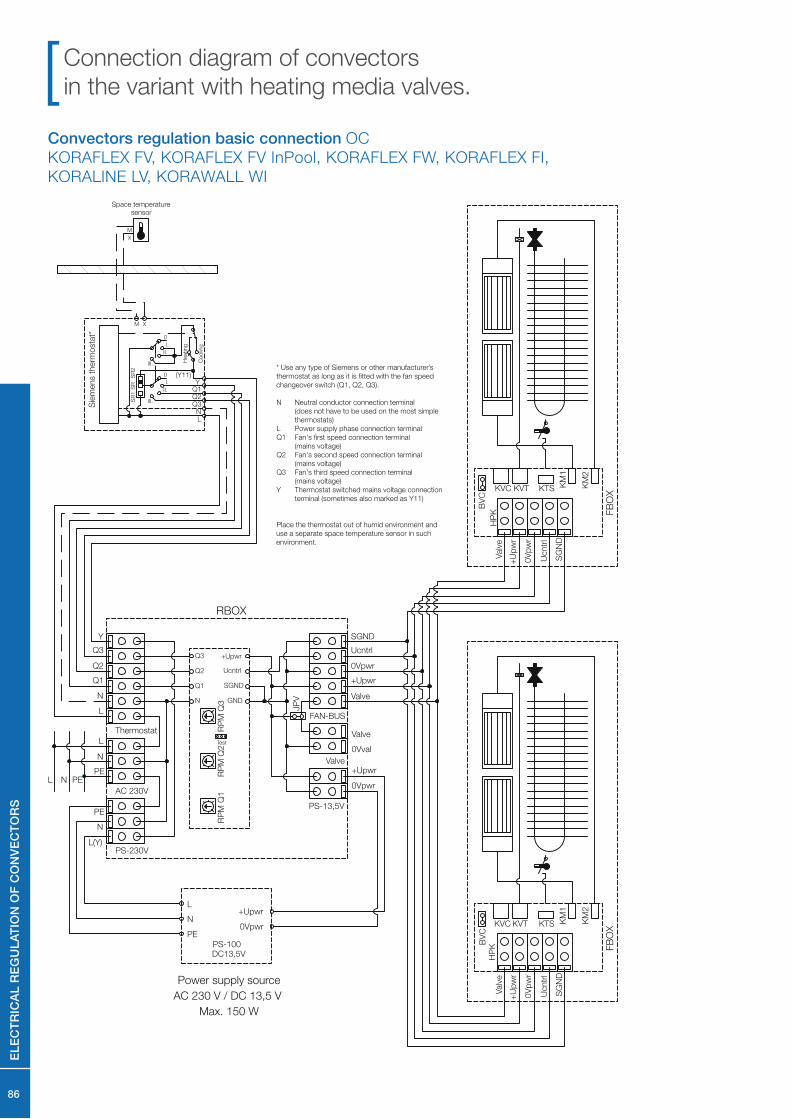
Convectors regulation basic connection OC
KORAFLEX FV, KORAFLEX FV InPool, KORAFLEX FW, KORAFLEX FI,
KORALINE LV, KORAWALL WI
HP
K
KTS KM
1
KM
2
FB
OX
KVC KVT
BV
C
SG
ND
Ucntr
l
Valv
e
+U
pw
r
0V
pw
r
RBOX
PE
N
L
PE
N
L(Y)
+Upwr
0Vpwr
SGND
Ucntrl
0Vpwr
+Upwr
ValveN
L
Q3
Q2
Q1
Y
Thermostat
AC 230V
0Vval
Valve
JP
V
PS-230V
PS-13,5V
Valve
FAN-BUS
PENL
Sie
mens t
herm
osta
t* 0
I.
I.
0
III.
II.
II.
III.
SR
SR
1S
R2
Heating
Coolin
g
LN
Y (Y11)
Q3Q2Q1
PS-100DC13,5V
PE
N
L+Upwr
0Vpwr
GND
SGND
Ucntrl
+Upwr
N
Q3
Q2
Q1
HP
KKTS K
M1
KM
2
FB
OX
KVC KVTB
VC
SG
ND
Ucntr
l
Valv
e
+U
pw
r
0V
pw
r
Test
RP
M Q
1R
PM
Q2
RP
M Q
3
Power supply source
AC 230 V / DC 13,5 V
Max. 150 W
XM
X
M
Space temperaturesensor
* Use any type of Siemens or other manufacturer’s
thermostat as long as it is fitted with the fan speed
changeover switch (Q1, Q2, Q3).
N Neutral conductor connection terminal
(does not have to be used on the most simple
thermostats)
L Power supply phase connection terminal
Q1 Fan's first speed connection terminal
(mains voltage)
Q2 Fan's second speed connection terminal
(mains voltage)
Q3 Fan's third speed connection terminal
(mains voltage)
Y Thermostat switched mains voltage connection
terminal (sometimes also marked as Y11)
Place the thermostat out of humid environment and
use a separate space temperature sensor in such
environment.
Connection diagram of convectors
in the variant with heating media valves.
EL
EC
TR
ICA
L R
EG
UL
AT
ION
OF
CO
NV
EC
TO
RS

87
OC convectors regulation connection
KORAFLEX FV, KORAFLEX FV InPool, KORAFLEX FW, KORAFLEX FI,
KORALINE LV, KORAWALL WI BMS control (Building Management System)
BMS Output module1× Potential-free contact (min. 24 V/1 A) 1× Analogue output (0 - 10 V/10 mA)K Valve control switching contactUcntrl analogue output for fan's speed control 0Vsgnd signal ground
Modul BMS
PS-100DC13,5V
PE
NLA
C 2
30
V
PE
N L
+U
pw
r
0V
pw
r
HPK
KT
S
KM1
KM2
FBOX
KV
CK
VT
BVC
SGND
Ucntrl
Valve
+Upwr
0Vpwr
HPK
KT
S
KM1
KM2
FBOX
KV
CK
VT
BVC
SGND
Ucntrl
Valve
+Upwr
0Vpwr
K1
2
K1
1
K
0V
sg
nd
Ucntr
l
Actuator
BMS - BUS
HPK
KTS
KM1
KM2
FBOX
KV
CK
VT
BVC
SGND
Ucntrl
Valve
+Upwr
0Vpwr
HPK
KTS
KM1
KM2
FBOX
KV
CK
VT
BVC
SGND
Ucntrl
Valve
+Upwr
0Vpwr
Power supplysource
AC 230 V / DC 13,5 V
Max. 150 W
Power supplysource
AC 230 V / DC 13,5 V
Max. 150 W
Thermostat
(Siemens)
PS-100DC13,5V
RBOX
+U
pw
r
0V
pw
r
SG
ND
Ucntr
l
0V
pw
r
+U
pw
r
Valv
e
0V
val
Valv
e
JPVPS-13,5V Valve FAN-BUS
Test
PE
N LPE
NL(Y
)
NL Q3
Q2
Q1
Y
ThermostatPS-230V AC 230V
PE
NLA
C 2
30V
PE
N L
+U
pw
r
0V
pw
r
NL
Q3
Q2
Q1 Y
RPM Q1 RPM Q2 RPM Q3
HPK
KTS
KM1
KM2
FBOX
KV
CK
VT
BVC
SGND
Ucntrl
Valve
+Upwr
0Vpwr
PS-100DC13,5V
RBOX
+U
pw
r
0V
pw
r
SG
ND
Ucntr
l
0V
pw
r
+U
pw
r
Valv
e
0V
val
Valv
e
JPVPS-13,5V Valve FAN-BUS
Test
PE
N LPE
NL(Y
)
NL Q3
Q2
Q1
Y
ThermostatPS-230V AC 230V
PE
N L
+U
pw
r
0V
pw
r
RPM Q1 RPM Q2 RPM Q3
HPK
KTS
KM1
KM2
FBOX
KV
CK
VT
BVC
SGND
Ucntrl
Valve
+Upwr
0Vpwr
OC convectors regulation connection
KORAFLEX FV, KORAFLEX FV InPool, KORAFLEX FW, KORAFLEX FI,
KORALINE LV, KORAWALL WI with more DC power supply sources
EL
EC
TR
ICA
L R
EG
UL
AT
ION
OF
CO
NV
EC
TO
RS

88
Example of the design calculation of the output
of the DC power supply
Acoustics
The electrical input must be calculated in terms of regulation so
that the correct size of the DC power supply source is selected.
The total input power will be a sum of all input power of the
convectors with forced convection which will be controlled
through one thermostat.
Apart from the input power one of the main parameters is the
noise level of the fan convectors. Manufacturer develops and
designs its products so that they do not exceed under any
circumstances the specified noice levels laid down by the health
standards for this type of equipment. Generally this limit is 30
dB (A) of the sound power that means that the product does
not exceed this limit at the minimum speed. Products marked
with the logo OC has been optimized for the noise/
performance ratio.
Manufacturer uses in its products always the most advanced
technology, as well as in the case of the fans. The used fans are
equipped with a patented disc engine with permanent magnets.
Among the main benefits is belong a significant noise reduction
and a low energy consumption compared to commercially
available fans with the rotor and stator.
Manufacturer indicates in its materials a parameter to assess
the noise level the acoustic pressure Lp (A) measured at 1 m
from the source. The measurements were carried out by
an authorised test laboratory.
The values of the sound power are available on request.
Acoustic pressure
The acoustic pressure is a change of the air pressure generated
by a source of noise. Such pressure fluctuations are measured
in N/m2 and expressed by the symbol "p". The acoustic
pressure represents the measure of volume. It depends on the
distance between the source of the noise and the place of the
measurement and also on the characteristics of the space.
Sound power
The energy converted by a piece of equipment (the source
of sound) to sound is referred to the sound power. This sound
power is brought to the air in the form of pressure fluctuations.
The sound power is not a directly measurable quantity. It is
determined by integrating of the acoustic pressure in the form
of a hemisphere or a sphere around the sound source.
The acoustic pressure is on this basis a quantity that is
independent of space and distance. It is used for all further
calculations. On request, will provide values of sound power of
its OC products. Although the acoustic pressure level and sound
power level use the same unit (dB), they are two different physical
quantities. The sound power level is the sound generated at the
sound source (energy introduced to the space) while the acoustic
pressure level is the sound registered at a certain distance from
the sound source. This means that the sound power level is
generally higher than the acoustic pressure level.
For example:
According to the project we have the following fan-coil unit types:
2 pcs of KORAFLEX FV 160/9/28 – we find the input power of 12 W in the table
1 pc of KORALINE LV 240/15/18 – we find the input power of 22.5 W in the table
2 pcs of KORAWALL WI 100/45/11 – we find the input power of 8 W in the table
(optionally 4 pieces of thermoelectric drives –
4 x 1.8 W = 7.2 W)
Total power input:
12 + 12 + 22.5 + 8 + 8 + (7) = 62.5 W (69.5 W)
Select source rated 100 W.
100
0 23.4 31.7 3
8 / 13.5
Off 1 2
0 291 407 5
Case with noise-absorbing foilFor further noise reduction, it is possible to order a convectors
case fi tted with noise-absorbing foil. The foil reduces the noisiness
by 1 to 3 dB depending on the type, length and speed of the
convectors.
Anti-noise foil
Anti-noise foil – cross section
acoustically absorbent sheet
EL
EC
TR
ICA
L R
EG
UL
AT
ION
OF
CO
NV
EC
TO
RS
89
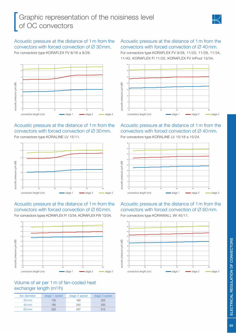
Acoustic pressure at the distance of 1 m from the
convectors with forced convection of ∅ 30 mm.For convectors type KORAFLEX FV 8/16 a 8/28.
Acoustic pressure at the distance of 1 m from the
convectors with forced convection of ∅ 40 mm.For convectors type KORAFLEX FV 9/28, 11/20, 11/28, 11/34,
11/42, KORAFLEX FI 11/20, KORAFLEX FV InPool 13/34.
Graphic representation of the noisiness level
of OC convectors
fan diameter stage 1 speed stage 2 speed stage 3 speed
30 mm 135 180 225
40 mm 180 240 300
60 mm 325 437 512
Volume of air per 1 m of fan-cooled heat
exchanger length (m3/h)
aco
ust
ic p
ress
ure
Lp
A (d
B)
aco
ust
ic p
ress
ure
Lp
A (d
B)
convectors length (cm)convectors length (cm) stage 1 stage 2 stage 3 stage 1 stage 2 stage 3
Acoustic pressure at the distance of 1 m from the
convectors with forced convection of ∅ 30 mm.For convectors type KORALINE LV 15/11.
Acoustic pressure at the distance of 1 m from the
convectors with forced convection of ∅ 40 mm.For convectors type KORALINE LV 15/18 a 15/24.
aco
ust
ic p
ress
ure
Lp
A (d
B)
aco
ust
ic p
ress
ure
Lp
A (d
B)
convectors length (cm)convectors length (cm) stage 1 stage 2 stage 3 stage 1 stage 2 stage 3
Acoustic pressure at the distance of 1 m from the
convectors with forced convection of ∅ 60 mm.For convectors types KORAFLEX FI 13/34, KORAFLEX FW 13/34.
Acoustic pressure at the distance of 1 m from the
convectors with forced convection of ∅ 60 mm.For convectors type KORAWALL WI 45/11.
aco
ust
ic p
ress
ure
Lp
A (d
B)
aco
ust
ic p
ress
ure
Lp
A (d
B)
convectors length (cm)convectors length (cm) stage 1 stage 2 stage 3 stage 1 stage 2 stage 3
EL
EC
TR
ICA
L R
EG
UL
AT
ION
OF
CO
NV
EC
TO
RS

90
Pressure losses of convectors
0
50
100
150
200
250
300
350
400
0 50 100 150 200 250 300 350 400 450 500
KORAFLEX FK 9/16, 11/16
KORABASE 10
KO
RA
BA
SE
10
specifi
c p
ress
ure
dro
p R
(P
a/m
)
water mass fl ow rate qM (kg/h)
1500
2000
2500
3000200 cm 220 cm 240 cm 260 cm 280 cm 300 cm
0
500
1000
0 50 100 150 200 250 300 350 400 450 500
KORAFLEX FK 9/20, 9/28, 11/20, 11/28
KORALINE 9/18 and 9/24, KORABASE 20
KORAFLEX FV 8/28, 9/28, 11/28
KORAFLEX FV InPool 13/34
KO
RA
BA
SE
20
pre
ssure
loss
es
∆p
(P
a)
water mass fl ow rate qM (kg/h)
80 cm 100 cm 120 cm 140 cm 160 cm 180 cm
200 cm 220 cm 240 cm 260 cm 280 cm 300 cm
600
800
1000
1200
1400
0
200
400
0 50 100 150 200 250 300 350 400 450 500
KORAFLEX FK 15/28, 19/28, 30/28, 45/28
KORALINE LK 15/18, 30/18, 45/18, 60/18
KORABASE 22
KO
RA
BA
SE
22
pre
ssure
loss
es
∆p
(P
a)
water mass fl ow rate qM (kg/h)
80 cm 100 cm 120 cm 140 cm 160 cm 180 cm
200 cm 220 cm 240 cm 260 cm 280 cm 300 cm
1500
2000
2500
3000
3500
0
500
1000
0 50 100 150 200 250 300 350 400 450 500
KORAFLEX FK 15/34, 19/34, 30/42, 45/42
KORALINE LK 15/24, 45/24, 60/24
KORABASE 33
KO
RA
BA
SE
33
pre
ssure
loss
es
∆p
(P
a)
water mass fl ow rate qM (kg/h)
80 cm 100 cm 120 cm 140 cm 160 cm 180 cm
200 cm 220 cm 240 cm 260 cm 280 cm 300 cm
800
1000
1200
1400
1600
1800
2000
0
200
400
600
800
0 50 100 150 200 250 300 350 400 450 500
KORAFLEX 9/34, 11/34
KORAFLEX FV 11/34, KORABASE 30
KO
RA
BA
SE
30
pre
ssure
loss
es
∆p
(P
a)
water mass fl ow rate qM (kg/h)
80 cm 100 cm 120 cm 140 cm 160 cm 180 cm
200 cm 220 cm 240 cm 260 cm 280 cm 300 cm
0
500
1000
1500
2000
2500
3000
3500
4000
4500
5000
5500
6000
0 50 100 150 200 250 300 350 400 450 500
KORAFLEX FK 9/42, 11/42
KORAFLEX FV 11/42
KO
RA
BA
SE
40
pre
ssure
loss
es
∆p
(P
a)
water mass fl ow rate qM (kg/h)
80 cm 100 cm 120 cm 140 cm 160 cm 180 cm
200 cm 220 cm 240 cm 260 cm 280 cm 300 cm
PR
ES
SU
RE
LO
SS
ES
OF
CO
NV
EC
TO
RS
91
0
1000
2000
3000
4000
5000
6000
7000
8000
9000
10000
11000
12000
0 50 100 150 200 250 300 350 400 450 500
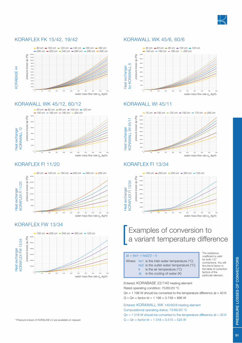
KORAFLEX FK 15/42, 19/42
KO
RA
BA
SE
44
pre
ssure
loss
es
∆p
(P
a)
water mass fl ow rate qM (kg/h)
80 cm 100 cm 120 cm 140 cm 160 cm 180 cm
200 cm 220 cm 240 cm 260 cm 280 cm 300 cm
0
500
1000
1500
2000
2500
3000
3500
4000
0 50 100 150 200 250 300 350 400 450 500
KORAWALL WK 45/6, 60/6
Heat
exc
hang
er
for
KO
RA
WA
LL 6
pre
ssure
loss
es
∆p
(P
a)
water mass fl ow rate qM (kg/h)
40 cm 60 cm 80 cm 100 cm 120 cm
140 cm 160 cm 180 cm 200 cm
0
1000
2000
3000
4000
5000
6000
0 50 100 150 200 250 300 350 400 450 500
Heat exc
hanger
KO
RA
WA
LL 1
2
pre
ssure
loss
es
∆p
(P
a)
water mass fl ow rate qM (kg/h)
40 cm 60 cm 80 cm 100 cm 120 cm
140 cm 160 cm 180 cm 200 cm
KORAWALL WK 45/12, 60/12
0
5000
10000
15000
20000
25000
30000
0 50 100 150 200 250 300 350 400 450 500
Heat exc
hanger
KO
RA
FLE
X F
I 11/2
0
pre
ssure
loss
es
∆p
(P
a)
water mass fl ow rate qM (kg/h)
80 cm 120 cm 160 cm 200 cm 240 cm 280 cm
KORAFLEX FI 11/20
0
10000
20000
30000
40000
50000
60000
0 50 100 150 200 250 300 350 400 450 500
Heat
exc
hang
er
KO
RA
FLE
X F
W 1
3/3
4
pre
ssure
loss
es
∆p
(P
a)
water mass fl ow rate qM (kg/h)
150 cm 200 cm 250 cm 300 cm 120 cm
KORAFLEX FW 13/34
0
1000
2000
3000
4000
5000
6000
7000
8000
9000
0 50 100 150 200 250 300 350 400 450 500
KORAWALL WI 45/11
Heat
exc
hang
er
KO
RA
WA
LL W
I 45/1
1
pre
ssure
loss
es
∆p
(P
a)
water mass fl ow rate qM (kg/h)
75 cm 100 cm 125 cm 150 cm 175 cm 200 cm
0
2000
4000
6000
8000
10000
12000
14000
16000
0 50 100 150 200 250 300 350 400 450 500
KORAFLEX FI 13/34
Heat
exc
hang
er
KO
RA
FLE
X F
I 1
3/3
4
pre
ssure
loss
es
∆p
(P
a)
water mass fl ow rate qM (kg/h)
150 cm 200 cm 250 cm 300 cm 120 cm
Examples of conversion to
a variant temperature difference
Entered: KORABASE 22/140 heating element
Rated operating condition: 75/65/20 °C
Qn = 1 198 W should be converted to the temperature difference ∆t = 40 K
Q = Qn × factor kt = 1 198 × 0.748 = 896 W
Entered: KORAWALL WK 140/60/6 heating element
Computational operating status: 75/65/20 °C
Qn = 1 018 W should be converted to the temperature difference ∆t = 30 K
Q = Qn × factor kt = 1 018 × 0.515 = 525 W
∆t = (tw1 + tw2)/2 – ti
Where: tw1 is the inlet water temperature (°C)
tw2 is the outlet water temperature (°C)
ti is the air temperature (°C)
∆t is the cooling of water (K)
The resistance
coefficient is valid
for both 1/2"
connections. You will
find the kt factor in
the table of correction
factors of the
particular element.
PR
ES
SU
RE
LO
SS
ES
OF
CO
NV
EC
TO
RS
* Pressure losses of KORALINE LV are available on request.
92
General information about products
Heating elements are produced using the state-of-the-art
technologies. Most production operations are executed on CNC
machines. The surface of elements is treated with powder coating
of epoxy-polystyrene paints on an environment-friendly line. In-
house production of high performance heat exchangers (copper
pipe, aluminium lamellas) guarantees high quality and wide variety
of products offered. To achieve an "invisible" impression you can
order a black coated exchanger.
The case supplied as the standard is made of a black coated gal-
vanised steel sheet. For use in wet environments you can order a
case of a high corrosion resistance stainless steel. Thanks to our
advanced production technology we are able to produce atypical
dimensions, including angled and arc convectors' designs.
The shortest possible delivery periods are offered, from 3 to 10
working days. Guaranteed warranty and after-warranty service.
Transport and
storage instruction
Quality Warranties
Maintenance
During transport the elements must be handled with extreme care
and must be secured against motion and damage. The trans-
port and storage area must be dry and protected from climatic
influences.
Manufacturer is a holder of the certified quality management system
as per ISO 9001:2008. The products are manufactured and tested
according to EN 422. By using CE mark the producer confirms
that the convectors are in conformity with the characteristics stated
in the Declaration of Performance issued in conformity with the
directive of EP and the Council (EU) No. 305/2011. This conformity
was approved by the notified body No.1015, Strojírenský zkušební
ústav, s.p. Brno.
The products are subject to 2-year warranty. 10-year warranty is
provided for the tightness of the heat exchanger. Full service and
warranty terms and conditions are available on demand.
Manufacturer KORADO, a.s. is not responsible for damage cau-
sed by improper installation, or damages arising from poor electri-
cal or thermal installations (such as fluctuating voltage or hydraulic
pressure which deviates significantly from normal values).
Manufacturer reserves the right to change technical specifications
without a prior notice.
The convectors must be kept clean and especially before the
heating season any dirt and dust should be removed from the
convectors. The fan convectors must be checked if the fans are
not mechanically blocked (by fallen objects, a layer of dust, etc.).
Universal
regulation
Forced
convection
Cooling Dry-cooling Minimal
Energy
consumption
Higher
performance
Natural
convection
Quiet
operation
Heating Swimming
pools
design
Environmentally
friendly
Information
GE
NE
RA
L I
NF
OR
MA
TIO
N O
F P
RO
DU
CT
S
Proven heating and cooling performances