koken dam 02
TRANSCRIPT
Foundation treatment Foundation treatment (grout) for dam (grout) for dam constructionconstruction
Hydraulic Engineering Consultants Corp.2169 Tran Quoc Thao, Dist.3, HCMC
http://www.hec2.com.vn
Koken Boring Machine Co.,Ltd1st Floor, Mejiro Nakano Bldg., 17-22, Takada 2-Chome, Toshima-ku, Tokyo 171-8572
http://www.koken-boring.co.jp
IntroductionIntroductionDefinition of groutInjection of a cement based material to fill cracks or clearance
-Rock grouting : rock stabilization, impermeation-Chemical grouting : impermeation-Jet grouting : soil stabilization-Sleeve grouting : soil stabilization
Grouting for dam constructionTo improve geological characters of rock and/or soil at foundation area of dam with pressurized cement based material into the ground. And also to fill the clearance of structures injecting grout material

Type and purpose of groutType and purpose of groutConsolidation/Blanket grout
Curtain grout
Back fill groutOthers
-Joint grout-Contact grout
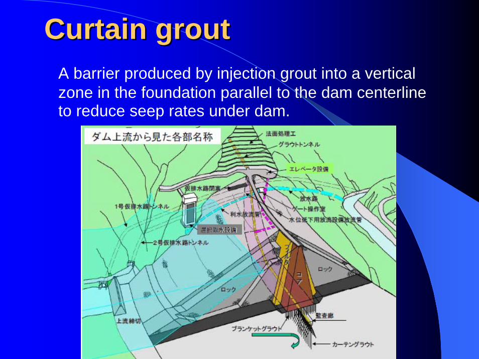
A barrier produced by injection grout into a vertical zone in the foundation parallel to the dam centerline to reduce seep rates under dam.
Curtain groutCurtain grout
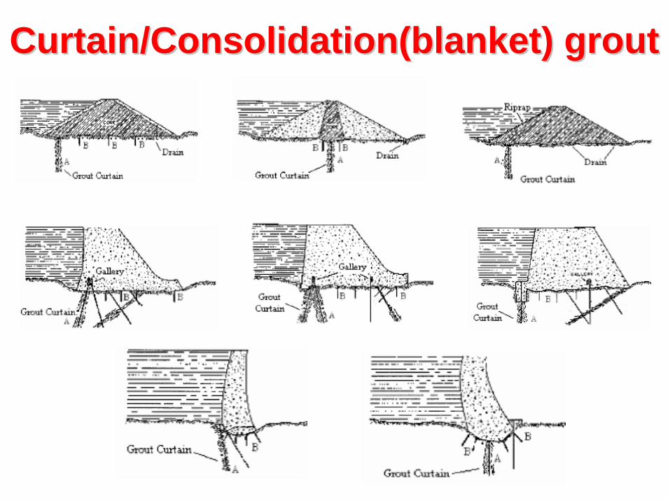
Curtain/Consolidation(blanket) groutCurtain/Consolidation(blanket) grout

Filling any voids existing with cement grout or mortar, e.g.., between a concrete tunnel lining and the surrounding rock.
Back fill groutBack fill grout
Other groutOther grout-Joint grout : Grout joint parts between concrete and concrete-Contact grout : Grout for contact between existing concrete structure and steel pipe or new concrete structure
Back fill groutBack fill grout
Contact grout
Joint grout
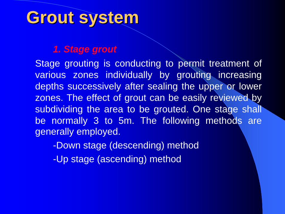
1. Stage groutStage grouting is conducting to permit treatment of various zones individually by grouting increasing depths successively after sealing the upper or lower zones. The effect of grout can be easily reviewed by subdividing the area to be grouted. One stage shall be normally 3 to 5m. The following methods are generally employed.
-Down stage (descending) method-Up stage (ascending) method
Grout systemGrout system
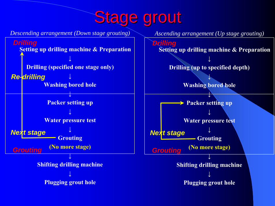
Descending arrangement (Down stage grouting)
Setting up drilling machine & Preparation↓
Drilling (specified one stage only)↓
Washing bored hole↓
Packer setting up↓
Water pressure test↓
Grouting(No more stage)
↓Shifting drilling machine
↓Plugging grout hole
Stage groutStage groutDrilling
Re-drilling
Grouting
Next stage
Ascending arrangement (Up stage grouting)
Setting up drilling machine & Preparation↓
Drilling (up to specified depth)↓
Washing bored hole↓
Packer setting up↓
Water pressure test↓
Grouting(No more stage)
↓Shifting drilling machine
↓Plugging grout hole
Drilling
Grouting
Next stage

2. Lu(Lugeon) testIn order to measure permeability of dam foundation area, lugeon test shall be conducted. Lu(lugeonvalue) is water volume injected at 10kgf/cm2 for 10 minutes per meter. The target Lu value after foundation treatment is generally 3 to 5.
Grout systemGrout system
Stage Pressure (bar)Time duration of each step
Pilot/Control hole Other hole
1st 1→3→1 9 min. 5 min.
2nd 2→5→2 9 min. 5 min.
3rd 2→5→6→5→2 9 min. 5 min.
4th 2→5→7→5→2 9 min. 5 min.
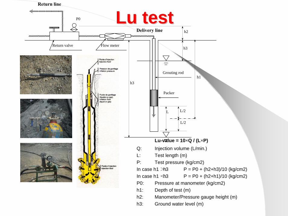
Lu-value = 10×Q / (L×P)Q: Injection volume (L/min.)L: Test length (m)P: Test pressure (kg/cm2)In case h1 >h3 P = P0 + (h2+h3)/10 (kg/cm2)In case h1 <h3 P = P0 + (h2+h1)/10 (kg/cm2)P0: Pressure at manometer (kg/cm2)h1: Depth of test (m)h2: Manometer/Pressure gauge height (m)h3: Ground water level (m)
Lu testLu test
h1
h2
h3
h3
L
L/2
L/2
P0
Return line
Delivery line
Grouting rod
Packer
Return valve Flow meter
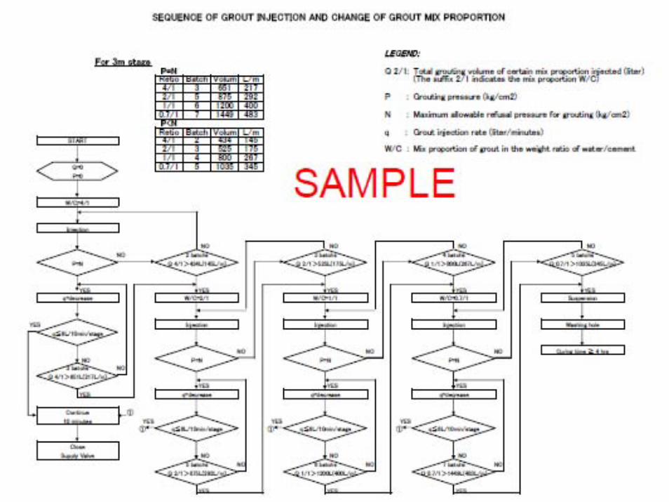
3. Grout-Mix ratioBased on Lu test result, the first mix ratio of grout shall be determined. Thin grout travels farther than thick grout. Therefore, it is generally to start with a thin mixture which is 4/1 or 5/1(W/C) mixing ratio. Then, the mixture shall be changed to thick proportion.-Grout pressureThe maximum grout pressure shall be determined based on grout test result not exceeding the critical pressure of original ground.
Grout systemGrout system
4.Back fill/contact/joint groutThe grout for filling purpose is not necessary to change the grout mixing ratio. And the grout shall be conducted with ow grouting pressure not to damage the existing structure.
Grout systemGrout system
Evaluation of grout resultEvaluation of grout result1. Producing lugeon mapStandard lugeon test or instant lugeon test shall be conducted before grouting at every stage. The result shall be showing on a map for evaluating grout effect. The map shall be produced every row(primarily, secondary……).
2. Producing grout intake mapActual grout intake which is injected cement volume per meter shall be calculated and shown on a grout intake map for all grout. The map also shall be produced for every row.
Evaluation of grout resultEvaluation of grout result3. Evaluation of groutThe results of lugeon map and grout intake map shall be evaluated. Lugeon value and grout intake is basically related. If a stage, where is high lugeonvalue, results low grout intake. The grout will be considered non effective or fairer of grout. In this case, additional grout shall be conducted.
4. Check holeCheck hole shall be conducted for verifying the effect of grouting works. The grout is completed when the measured Lu value from check hole achieves the target Lu value.
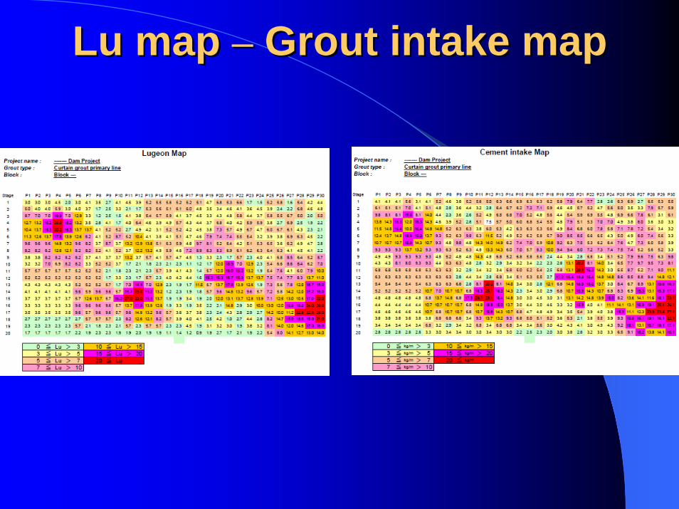
Lu map Lu map –– Grout intake mapGrout intake map
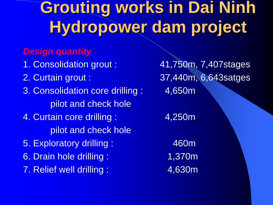
Grouting works in Dai Grouting works in Dai NinhNinhHydropower dam projectHydropower dam project
Design quantity1. Consolidation grout : 41,750m, 7,407stages2. Curtain grout : 37,440m, 6,643satges3. Consolidation core drilling : 4,650m
pilot and check hole4. Curtain core drilling : 4,250m
pilot and check hole5. Exploratory drilling : 460m6. Drain hole drilling : 1,370m7. Relief well drilling : 4,630m
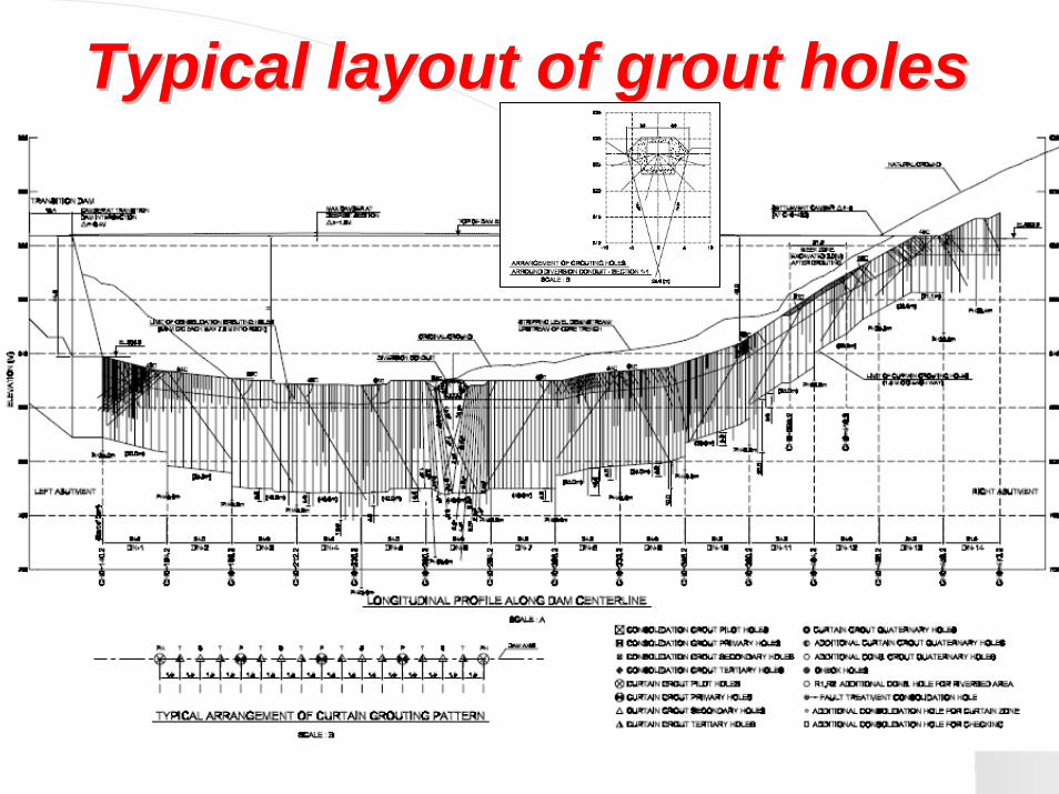
Typical layout of grout holesTypical layout of grout holes
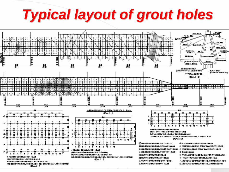
Typical layout of grout holesTypical layout of grout holes

--DrillingDrilling--Rotary drilling Rotary drilling on stage Rotary drilling on stage
Rotary percussion drilling Rotary percussion drillingDrilling site & core

--GroutingGrouting--Main plant Sub plant Flow meter
Manifold GroutingPacker & gas regulator
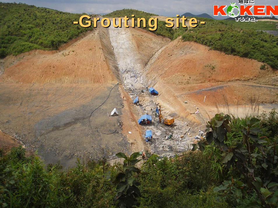
--Grouting siteGrouting site--
Latest grout technologyLatest grout technology
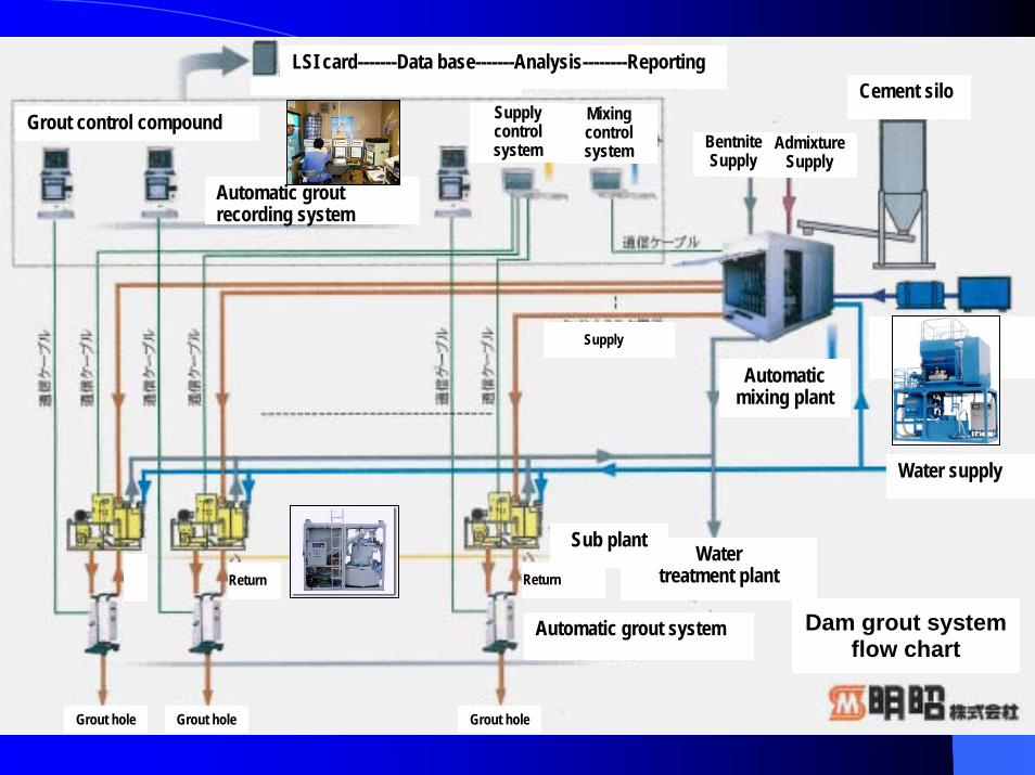
Dam grout system flow chart
Grout hole Grout hole Grout hole
Watertreatment plant
Sub plant
Water supply
ReturnReturn
Automatic grout system
Supply
Automaticmixing plant
Cement siloGrout control compound
Automatic groutrecording system
Supplycontrol system
Mixingcontrol system
LSI card-------Data base-------Analysis--------Reporting
AdmixtureSupply
BentniteSupply

KOKENKOKEN PRODUCTPRODUCT–– for Dam Constructionfor Dam Construction--
Anchoring Drain hole drilling
GroutingShaft drilling