kern 572/573/kb/ds/fkb gb - frank's hospital...
TRANSCRIPT

572/573/KB/DS/FKB-BA-defsi-0651 24
GB
KERN 572/573/KB/DS/FKB Version 5.1 05/2006 Operating Instructions Electronic Precision and Platform Balances
Table of contents:
1 MODE - MENUE __________________________________________________________ 26
2 Technical data _____________________________________________________________ 27 2.1 KERN 572 __________________________________________________________________ 27 2.2 KERN 573 __________________________________________________________________ 28 2.3 KERN KB __________________________________________________________________ 29 2.4 KERN FKB _________________________________________________________________ 29 2.5 KERN DS ___________________________________________________________________ 30
3 Fundamental information (general) ___________________________________________ 31 3.1 Intended use_________________________________________________________________ 31 3.2 Inappropriate use ____________________________________________________________ 31 3.3 Guarantee __________________________________________________________________ 31 3.4 Monitoring the test substances__________________________________________________ 31
4 Fundamental safety information ______________________________________________ 32 4.1 Observe the information in the operating instructions ______________________________ 32 4.2 Staff training ________________________________________________________________ 32
5 Transport and storage_______________________________________________________ 32 5.1 Acceptance check ____________________________________________________________ 32 5.2 Packaging___________________________________________________________________ 32
6 Unpacking, installation and commissioning _____________________________________ 32 6.1 Place of installation, place of use ________________________________________________ 32 6.2 Unpacking __________________________________________________________________ 33
6.2.1 Installation _______________________________________________________________________ 33 6.3 Mains supply ________________________________________________________________ 33 6.4 Connecting peripheral equipment _______________________________________________ 33 6.5 Initial start-up _______________________________________________________________ 33 6.6 Adjustment _________________________________________________________________ 33 6.7 Adjusting ___________________________________________________________________ 33
6.7.1 Adjusting for verification (KERN 573) _________________________________________________ 34 6.8 Verification _________________________________________________________________ 34

572/573/KB/DS/FKB-BA-defsi-0651 25
7 Operation_________________________________________________________________ 35 7.1 Display control panel _________________________________________________________ 35 7.2 Operation ___________________________________________________________________ 36
7.2.1 Weighing with Tare ________________________________________________________________ 36 7.2.2 Count – Selection Preference Piece ____________________________________________________ 36 7.2.3 Percent % ________________________________________________________________________ 36 7.2.4 Formula Weighing _________________________________________________________________ 36 7.2.5 Tolerance Weighing ________________________________________________________________ 36 7.2.6 Adjust ___________________________________________________________________________ 38 7.2.7 Preselect Tare _____________________________________________________________________ 38 7.2.8 Auto Tare ________________________________________________________________________ 38 7.2.9 Speed ___________________________________________________________________________ 38 7.2.10 Auto Off_______________________________________________________________________ 38 7.2.11 Variable Factor__________________________________________________________________ 38 7.2.12 Preselect Unit ___________________________________________________________________ 38
7.3 Interface RS 232 C ___________________________________________________________ 40 7.4 RS 232 C Data output via interface RS 232 C _____________________________________ 40
7.4.1 There are 4 methods for the data output via RS 232 C______________________________________ 40 7.4.2 Description of the data transfer________________________________________________________ 41 7.4.3 Numerator________________________________________________________________________ 41
7.5 Printer _____________________________________________________________________ 41 7.6 Underfloor weighing __________________________________________________________ 41
8 Maintenance, upkeep, disposal________________________________________________ 42 8.1 Cleaning ____________________________________________________________________ 42 8.2 Maintenance, upkeep _________________________________________________________ 42 8.3 Disposal ____________________________________________________________________ 42
9 Troubleshooting ___________________________________________________________ 42
10 Declaration of conformity__________________________________________________ 43

572/573/KB/DS/FKB-BA-defsi-0651 26
1 MODE - MENUE
MODE
CAL?Mode
PLACE CALWEIGHT
Y
g N/Y Mode Esc
Preselect Units ? Mode
Y
b N/Y Mode Esc
AUTO OFF? N/Y Mode
weighing
REF=1 N/Y Mode Esc
COUNT? N/Y Mode
Y
REF=5 N/Y Mode Esc
REF=10 N/Y Mode Esc
REF=20 N/Y Mode Esc
% ? N/Y Mode
g, kg, oz, ozt,*, dwt, GN,lb, ct, tLT,tLH, tLM,tLS, tL, t,
mo, m, b, o,
Preselect Tare? Mode
Y 1 l 0.000g ModeY N - -
Variable Factor ? Mode
Y 1 l 0.000g ModeY N - -
2400Bd N/Y Mode Esc
PRINTER? Mode
Y
4800Bd N/Y Mode Esc
9600Bd N/Y Mode Esc
19200Bd N/Y Mode Esc
Numerator N/Y Mode Esc
AUTOPRINT N/Y Mode Esc
AUTOPRT PC N/Y Mode Esc
AUTOTARE? N/Y Mode
FAST 3 Mode
Manufacture Setting: Count?: YES REF10: YES 9600bd: YES Preselect Units?: g/kg Autotare: YES Fast: 3

572/573/KB/DS/FKB-BA-defsi-0651 27
2 Technical data 2.1 KERN 572
KERN 572-31 572-33 572-35 572-45 572-49 572-57 Readout 0,001 g 0,01 g 0,01 g 0,1 g 0,1 g 0,2 g
Weighing range 161 g 1.210 g 1.510 g 12.100 g 15.100 g 20.100 g
Taring range (subtractive) 161 g 1.210 g 1.510 g 12.100 g 15.100 g 20.100 g
Reproducibility 0,001 g 0,01 g 0,01 g 0,1 g 0,1 g 0,2g
Linearity ±0,003 g ±0,03 g ±0,03 g ±0,3 g ±0,3 g ± 0,6 g Minimum weight for counting parts 0,001 g 0,01 g 0,01 g 0,1 g 0,1 g 0,2 g
Test weight (included) tolerance as per M1 50 g (F1) 500 g 500 g 5.000 g 5.000g 5.000 g
Recommended adjusting weight F2
100g 1 kg 1 kg 10 kg 10 kg 10 kg
Verifiable No No No No No No
Stabilisation time (typical) 3 sec.
Permissible ambient temperature +10 °C ... + 40 °C
Casing (W x H x D) mm 180 x 310 x 90
Weighing plate mm Ø 106 Ø 150 Ø 150 160 x 200
Net weight kg 4
Interface Yes (RS232)

572/573/KB/DS/FKB-BA-defsi-0651 28
2.2 KERN 573 KERN 573-46 573-52 Class of accuracy II II
Readout (d) 0,1 g 0,2 g
Verification value (e) 1g 2g
Weighing range (max.) 6500 g 13000 g
Minimum load (Min) 5g 10g
Taring range (subtractive) 6500 g 13000 g
Reproducibility 0,1 g 0,2 g
Linearity ±0,2 g ±0,4 g
Minimum weight for counting parts 0,3 g 0,6 g
Test weight (included) tolerance as per M1 5000 g 5000 g
Recommended adjusting weight F2 5 kg 10 kg
Verifiable Yes Yes Air humidity max. 80 % relative (not condensing)
Stabilization time 2 sec.
Permissible ambient temperature 0° C to + 50° C
Temperature range for verifiable applications +10 °C ... + 40 °C
Casing (W x H x D) mm 180 x 310 x 90
Weighing plate mm 160 x 200 160 x 200
Data interface Yes (RS232)
Weighing units g, kg
Vibratory filter Yes
Net weight (kg) 4

572/573/KB/DS/FKB-BA-defsi-0651 29
2.3 KERN KB
KERN KB100-3 KB1000-2 KB10000-1 Readout 0,001 g 0,01 g 0,1 g
Weighing range 101 g 1010 g 10.100 g
Taring range (subtractive) 101 g 1000 g 10.100 g
Reproducibility 0,001 g 0,01 g 0,1 g
Linearity ±0,003 g ±0,03 g ±0,3 g
Minimum weight for counting parts 0,001 g 0,01 g 0,1 g
Test weight (included) tolerance as per M1 50 g 200 g 1.000 g
Adjusting weight (not included)tolerance as per F2
100 g F1 1000 g 10.000 g
Verifiable No No No
Stabilisation time (typical) 3 sec.
Permissible ambient temperature + 10° C … + 40° C
Casing (W x H x D) mm 165 x 230 x 85
Weighing plate mm Ø 85 130 x 130 150 x 170
Net weight kg 1,8 2,7
Data interface Yes (RS232)
2.4 KERN FKB KERN FKB 4K0.5 FKB 8K0.1 FKB 16K0.2 FKB 36K0.5 FKB 65K1 Readout 0,05 g 0,1 g 0,2 g 0,5 g 1 g
Weighing range 4.100 g 8.100 g 16.100 g 36.100 g 65.100 g
Taring range (subtractive) 4.100 g 8.100 g 16.100 g 36.100 g 65.100 g
Reproducibility 0,05 g 0,1 g 0,2 g 0,05 g 1 g
Linearity 0,15 g 0,3 g 0,6 g 1,5 g 3 g
Minimum weight for counting parts
0,05 g 0,1 g 0,2 g 0,5 g 1 g
Adjusting weight (not included ) tolerance as per F2
2 kg 5 kg 10 kg 20 kg 50 kg
Air humidity max. 80% relative (not condensing)
Verifiable No
Stabilisation time (typical) 2 sec.
Permissible ambient temperature + 10 °C ... + 40 °C
Casing (W x H x D) mm 350 x 390 x 120
Weighing plate mm 340 x 240
Vibratory filter Yes
Net weight kg 6,5
Data interface Yes (RS232)

572/573/KB/DS/FKB-BA-defsi-0651 30
2.5 KERN DS
KERN DS4
K0.05 S DS8
K0.1S DS8 K0.1
DS16 K0.2
DS36 K0.5
DS36 K0.5L
DS65 K1
DS100 K1
DS150 K2
Readout 0,05 g 0,1 g 0,1 g 0,2 g 0,5 g 0,5 g 1g 1g 2g
Weighing range 4.100 g 8.100 g 8.100 g 16.100 g 36.100 g 36.100 g 65.100g 101.000g 151.000g
Taring range (subtractive)
4.100 g 8.100 g 8.100 g 16.100 g 36.100 g 36.100 g 65.100g 101.000g 151.000g
Reproducibility 0,05 g 0,1 g 0,1 g 0,2 g 0,5 g 0,5 g 1g 1g 2g
Linearity 0,15 g 0,3 g 0,3 g 0,6 g 1,5 g 1,5 g 3 g 3 g 6g
Minimum weight for counting parts
0,05 g 0,1 g 0,1 g 0,2 g 0,5 g 0,5 g 1g 1g 2g
Adjusting weight (not included ) tolerance as per F2
2 kg 5 kg 5 kg 10 kg 10 kg 20 kg 50 kg 50 kg 50 kg
Verifiable No
Stabilisation time (typical)
2 sec.
Permissible ambient temperature
+ 10 °C ... + 40 °C
Vibratory filter Yes
Casing (W x H x D) mm
228 x 228 x 70
315 x 305 x 70
450 x 350 x 115
Weighing plate mm
228x228
315 x 305
Net weight kg 5,5 8 12,5
Data interface Yes (RS232)
572/573/KB/DS/FKB-BA-defsi-0651 31
3 Fundamental information (general) It is essential to read through and observe the complete operating instructions before installing and commis-sioning.
3.1 Intended use The balance you have acquired serves to determine the weighing value of the material to be weighed. It is intended to be used as a “non-automatic“ balance, i.e. the material to be weighed is manually and carefully placed in the centre of the weighing plate. The weighing value can be read off after a stable weighing value has been obtained.
3.2 Inappropriate use Do not use the balance for dynamic weighing. In the event that small quantities are removed or added to the material to be weighed, incorrect weighing results can be displayed due to the “stability compensation“ in the balance. (Example: Slowly draining fluids from a container on the balance.) Do not leave a permanent load on the weighing plate. This can damage the measuring equipment. Be sure to avoid impact shock and overloading the balance in excess of the prescribed maximum load rating (max.), minus any possible tare weight that is already present. This could cause damage to the balance. Never operate the balance in hazardous locations. The series design is not explosion-proof. Structural alterations may not be made to the balance. This can lead to incorrect weighing results, faults concerning safety regulations as well as to destruction of the balance. The balance may only be used in compliance with the described guidelines. Varying areas of applica-tion/planned use must be approved by KERN in writing.
3.3 Guarantee The guarantee is not valid following
- non-observation of our guidelines in the operating instructions - use outside the described applications - alteration to or opening of the device - mechanical damage and damage caused by media, liquids - natural wear and tear - inappropriate erection or electric installation - overloading of the measuring equipment
3.4 Monitoring the test substances The metrology features of the balance and any possible available adjusting weight must be checked at regu-lar intervals within the scope of quality assurance. For this purpose, the answerable user must define a suit-able interval as well as the nature and scope of this check. Information is available on KERN’s home page (www.kern-sohn.com) with regard to the monitoring of balance test substances and the test weights required for this. Test weights and balances can be adjusted quickly and at a reasonable price in KERN’s accredited DKD calibration laboratory (return to national normal).

572/573/KB/DS/FKB-BA-defsi-0651 32
4 Fundamental safety information 4.1 Observe the information in the operating instructions Please read the operating instructions carefully before erecting and commissioning, even if you already have experience with KERN balances.
4.2 Staff training The device may only be operated and looked after by trained members of staff.
5 Transport and storage 5.1 Acceptance check Please check the packaging immediately upon delivery and the device during unpacking for any visible signs of external damage. In the case of visible damages please obtain a signature from the bearer to serve as confirmation of dam-age. Do not make alterations to the goods and packaging, do not remove any consignment parts. Report the damage to the parcel service immediately in writing ( within 24 hours).
5.2 Packaging Please retain all parts of the original packaging in case it should be necessary to return items at any time. Only the original packaging should be used for return consignments. Before despatch, disconnect all attached cables and loose/movable parts, remove weighing plate. Apply any intended transport security devices. Secure all parts, e.g. glass windshield, weighing plate, power unit etc., to prevent slipping and damage.
6 Unpacking, installation and commissioning
6.1 Place of installation, place of use The balance is constructed in such a way that reliable weighing results can be achieved under normal appli-cation conditions. By selecting the correct location for your balance, you will be able to work quickly and precisely. Therefore please observe the following at the place of installation:
- Place the balance on a firm, level surface; - Avoid extreme heat as well as temperature fluctuation caused by installing next to a radiator or in the
direct sunlight; - Protect the balance against direct draughts due to open windows and doors; - Avoid jarring during weighing; - Protect the balance against high humidity, vapours and dust; - Do not expose the device to extreme dampness for longer periods of time. Inadmissible bedewing
(condensation of air moisture on the device) can occur if a cold device is taken into a significantly warmer environment. In this case, please acclimatise the device for approx. 2 hours at room tem-perature after it has been disconnected from the mains.
- Avoid static charging of the material to be weighed, weighing container and windshield. Major display deviations (incorrect weighing results) are possible if electromagnetic fields occur as well as due to static charging and instable power supply. It is then necessary to change the location.

572/573/KB/DS/FKB-BA-defsi-0651 33
6.2 Unpacking Carefully remove the balance from its packaging, remove the plastic wrapping and position the balance in its intended working location.
6.2.1 Installation Install the balance in such a fashion that the weighing plate is absolutely horizonta
6.3 Mains supply Electric power supply is by means of the external mains supply circuit. The printed voltage level must comply with the local voltage. Only use original KERN mains supply circuits. The use of other makes is subject to approval by Kern.
6.4 Connecting peripheral equipment The balance must be disconnected from the mains before connecting or disconnecting additional equipment (printer, PC) to or from the data interface. Only use KERN accessories and peripheral equipment with your balance. These have been ideally coordina-ted to your balance.
6.5 Initial start-up A warm-up time of 15 minutes stabilises the measured values after switching on.
The accuracy of the balance depends on the local acceleration of the fall. Please be sure to observe the information in the chapter on adjusting.
6.6 Adjustment As the acceleration value due to gravity is not the same at every location on earth, each balance must be coordinated – in compliance with the underlying physical weighing principle - to the existing acceleration due to gravity at its place of location ( only if the balance has not already been adjusted to the location in the factory). This adjustment process must be carried out during the initial start-up, after change in location and variation of surrounding temperature. It is also recommendable to adjust the balance periodically during weighing operation in order to obtain exact measured values.
6.7 Adjusting Using a precision weight, the accuracy of the balance can be checked at any time and adjusted. Warning: With verified balances, this precision adjustment is not possible
Adjustment procedure: Check that the surrounding conditions are stable. A short warm-up time of about 15 minutes is recommended for stabilisation.

572/573/KB/DS/FKB-BA-defsi-0651 34
6.7.1 Adjusting for verification (KERN 573) General Information: Prior to the procedure of verification the balance has to be adjusted. Remark: The adjusting is only possible when not being blocked by the adjusting switch.
The switch for this step is located at the bottom of the housing between the two turning feet.
Switch to the right Adjusting function is released.
This setting has to be selected before starting the adjusting.
Executing the adjusting according to chapter 7.2 “Operation“.
After the adjusting has been completed successfully it is nec-essary to turn the adjusting switch to the left for blocking.
Switch to the left Adjusting function is blocked.
After the adjusting has been completed successfully the ad-justing has to be blocked by switching to the left.
The balance is now prepared for the procedure of verification.
After the verification the adjusting switch has to be secured by a verification mark against access.
6.8 Verification General: According to the EU guideline 90/384/EEC balances must be verified officially if they are to be used as fol-lows (legally regulated area):
a) For commercial transactions if the price of goods is determined by weighing b) For the production of medines in pharmacies as well as for analyses in the medical and pharmaceu-
tical laboratory c) For official purposes d) For the production of finished packages
In case of doubt, please contact your local office of weights and measures.
Verification information An EU qualification approval is available for those balances marked as appropriate for verification in the technical data. In the event that the balance is applied in an area subject to verification as described above, it must be officially verified and re-verified at regular intervals. Re-verification of a balance is carried out in compliance with the respective legal provisions of the states. The term of verification validity for balances in Germany, for example, is normally 2 years. The legal provisions of the country of use are to be observed.

572/573/KB/DS/FKB-BA-defsi-0651 35
7 Operation
7.1 Display control panel
Keyboard
ON / OFF
Print weighing result in MODE: No / descending
in % and counting mode: Form reference in MODE: Yes / ascending MODE configuration (see mode structure diagram page 2)
Formula weighing in MODE: to left Change g-pieces Unit changeover in MODE: to right Tare in MODE: back in weighing operation
Display-Symbol Meaning
==OVERLOAD== Overload: Weighing range has been exceeded
= ============ Underload: Weighing range has been fallen short of
<< . In counting and % mode: part too light
.
Automatic tare active
PTA .
Preselect tare Tare pre-selection active
D .
Difference in % during percentage weighing
Net .
Net weight of the components during formula preparation
SUM .
Gross weight of several components during formula prepa-ration
. Balance is in counting mode and currently displaying the weight value of the counting amount

572/573/KB/DS/FKB-BA-defsi-0651 36
7.2 Operation
7.2.1 Weighing with Tare
7.2.2 Count – Selection Preference Piece
7.2.3 Percent %
7.2.4 Formula Weighing
7.2.5 Tolerance Weighing

572/573/KB/DS/FKB-BA-defsi-0651 37

572/573/KB/DS/FKB-BA-defsi-0651 38
7.2.6 Adjust
7.2.7 Preselect Tare
7.2.8 Auto Tare
7.2.9 Speed
7.2.10 Auto Off
7.2.11 Variable Factor
7.2.12 Preselect Unit

572/573/KB/DS/FKB-BA-defsi-0651 39

572/573/KB/DS/FKB-BA-defsi-0651 40
7.3 Interface RS 232 C Technical Data
8-bit ASCII Code 1 start bit, 8 data bits, 1 stop bits, no parity bit Baud rate adjustable to 2400, 4800 and 9600 baud (default), 19200 baud Sup-D- 9 pol. is necessary . When working with an interface correct operation is secured only if the corresponding KERN-interface-
cable (max. 2m) is used.
Description of the jack Sup-D- 9 pol.
5 1
9 6
Pin 2: Transmit data Pin 3: Receive data Pin 5: Signal ground
Baudrate The Baud rate for the data transfer is adjusted with the MODE-key. The following example demonstrates how to set the Baud rate 4800. Select Baud rate Display1. Press MODE-key repeatedly until "PRINTER" is displayed. 2. Press YES-key. 3. Press MODE-key repeatedly until the desired Baud rate appears (for
instance 4800 Baud). 4. Press YES-key to select 4800 Baud. The tick-mark (X) confirms the new
setting. 5. Press MODE-key repeatedly until the balance displays in grams again,
or press tare key.
PRINTER? 2400 Baud
4800 Baud
4800 Baud X0,0 g
7.4 RS 232 C Data output via interface RS 232 C RS 232 C Data output via interface RS 232 C General information As a condition for the data transfer between the balance and a peripheral device (for instance printer, PC ...) both devise have to be set on the same interface parameter (for instance baud rate, parity ...).
7.4.1 There are 4 methods for the data output via RS 232 C Data output via PRINT-Key The printing process can be released by the PRINT-key. In this case the settings AUTOPRINT and AUT-PRINT PC should be deselected.
AUTOPRINT (Data output, after having loaded the balance) The setting AUTOPRINT is in the PRINTER-routine, and there it can be selected or deselected. When AUTOPRINT is active the actual weighing value will be sent via the RS 232 interface when the balance has been unloaded and then loaded after having achieved the stability.
AUTOPRINT PC (Continuous data output) The setting AUTPRINT PC is in the PRINTER-routine, and there it can be selected or deselected. When AUTOPRINT PC is active the actual weighing values will be sent continuously via the RS 232 interface.
Data output by transfer of remote controls The following functions can be released by the remote controls that will be transferred as ASCII signs to the balance.
t Tare. w a weighing value (or unstable) is sent via RS 232 interface. s a stable weighing value is sent via RS 232 interface. If the balance receives the command w or s, it acts without printing delay.

572/573/KB/DS/FKB-BA-defsi-0651 41
7.4.2 Description of the data transfer Structure of each data transfer:
Without Numerator:
Bit-Nr. 1 2 3 4 5 6 7 8 9 10 11 12 13 14 15 16 17 18 B B B B B B B B 0 . 0 B g B B CR LF B*
B*: = Blank or % in the range of zero point. B, 0, ., g: = Blank or weighing value with unit, depending on the load on the weighing plate. CR: = Carriage Return LF: = Line Feed
With Enumerator: Bit.Nr. 1 2 3 4 5 6 7 8 9 10 11 12 13 14 15 16 17 18 19 20 N N N B* B B B B B B B 0 . 0 B G B B CR LFN: = Enumerator
7.4.3 Numerator The Numerator is found under the menu point “Printer” and can be activated and deactivated. When editing data with the use of the print option, the range of the numerator will increase by one place.
7.5 Printer With the serial data output RS 232 a printer can be connected. The printout shows the weight in grams. When the counting mode is selected the number of pieces or the weight is printed. When the percent mode is selected, the percentage or the weight will be printed. Press The PRINT-key to print weighing results. Select the enumerator to number the weighing continuously. Turn off the balance or use the CLEAR function to Reset the enumerator to (000).
7.6 Underfloor weighing Objects which, because of their size or shape, cannot be put on the scale, can be weighed by means of un-derfloor weighing.
Proceed as follows:
• Switch off the balance.
• Turn the balance over, without loading the balance plate.
• Open the cover plate on the base of the balance.
• Hang on the hook for underfloor weighing .
• Place the balance over an opening.
• Hang the item to be weighed on the hook and carry out weighing.
! CAUTION !
Take care that the hooks used for the underfloor weighing are stable enough to hold the goods which you wish to weigh (risk of breakage). Always make sure that there are no living beings or materials below the load that could be injured or damaged.
! NOTE !
After completing the underfloor weighing, the opening in the floor of the balance must be closed again (dust protection).

572/573/KB/DS/FKB-BA-defsi-0651 42
8 Maintenance, upkeep, disposal
8.1 Cleaning Please disconnect the device from the operating voltage before cleaning. Only use a cloth dampened with mild suds and not aggressive cleaning agents (solvents or similar). Please ensure that fluids are not able to get into the device and rub off using a clean, soft cloth. Loose sample residue/powder can be removed carefully using a brush or hand vacuum cleaner. Remove any spilt material to be weighed immediately.
8.2 Maintenance, upkeep The device may only be opened by trained service engineers authorised by KERN. Disconnect from the mains supply before opening.
8.3 Disposal The operating company shall dispose of the packaging and the device in compliance with the valid national or regional law of the operating location.
9 Troubleshooting The balance should be switched off for a short time following an interruption in the programme sequence and disconnected from the mains supply. It is then necessary to repeat the weighing process from the be-ginning.
Help: Interruption Possible cause Weight display is not illuminated. • The balance is not switched on. • The mains supply connection has been interrupted
(mains cable not plugged in/faulty). • Power supply interrupted. . The weight display changes continually • Draught/air movement • Table/floor vibrations • The weighing plate is in contact with foreign mat-
ter.
• Electromagnetic fields / static charging (choose different location/switch off interfering device if possible)
The weighing result is obviously incorrect • The balance display is not set to zero • Adjustment is no longer correct. • Great fluctuations in temperature.
• Electromagnetic fields / static charging (choose different location/switch off interfering device if possible)
Switch the balance off if other error messages should appear and then switch on again. Contact the manu-facturer if the error message does not disappear.

572/573/KB/DS/FKB-BA-defsi-0651 43
10 Declaration of conformity
Declaration of conformity
The electronic precision and platform balances Typ: KERN 572-31
KERN 572-33 KERN 572-35 KERN 572-45 KERN 572-49 KERN 572-57 KERN KB 100-3 KERN KB1000-2 KERN KB10000-1
KERN DS4K0.05 S KERN DS8K0.1 + S KERN DS16K0.2 KERN DS36K0.5 + L KERN DS65K1 KERN DS100K1 KERN DS150K2
KERN FKB 4K0.05 KERN FKB 8K0.1 KERN FKB 16K0.2 KERN FKB 36K0.5 KERN FKB 65K1
Correspond to the production model described in the EC type-approval certificate
and to the requirements of the following EC directives:
EC EMC directive Version 89/336/ECC Applied harmonised norms, in particular EN 61326: 1997
+ A1: 1998 +A2:2001
EN 61000-3-2: 1995 + A1/A2 1998 + A14 2000
EN 61000-3-3: 1995
If a change is made to the above mentioned appliances without consulting KERN
this declaration will become invalid.
Date: 07/01/2004 Signature: Gottl. KERN & Sohn GmbH Management Gottl. KERN & Sohn GmbH, Ziegelei 1, D-72322 Balingen-Frommern, Tel. +49-07433/9933-0, Fax +49-07433/9933-149

572/573/KB/DS/FKB-BA-defsi-0651 44
KERN & Sohn GmbH D-72322 Balingen-Frommern Postfach 4052 E-Mail: [email protected]
Tel: 0049-[0]7433- 9933-0 Fax: 0049-[0]7433-9933-149 Internet: www.kern-sohn.com
Konformitätserklärungen
Declaration of conformity for apparatus with CE mark
Konformitätserklärung für Geräte mit CE-Zeichen Déclaration de conformité pour appareils portant la marque CE Declaración de conformidad para aparatos con disitintivo CE
Dichiarazione di conformitá per apparecchi contrassegnati con la marcatura CE English We hereby declare that the product to which this declaration refers conforms with the fol-
lowing standards.
Deutsch Wir erklären hiermit, daß das Produkt, auf das sich diese Erklärung bezieht, mit den nach-stehenden Normen übereinstimmt.
Français Nous déclarons avec cela responsabilité que le produit, auquel se rapporte la présente déclaration, est conforme aux normes citées ci-après.
Español Manifestamos en la presente que el producto al que se refiere esta declaración est´´a de acuerdo con las normas siguientes
Italiano Dichiariamo con ciò che il prodotto al quale la presente dichiarazione si riferisce è confor-me alle norme di seguito citate.
Balance lines: 573 Mark applied EU Directive Standards
89/336EEC EMC EN45501
EN55022
Date: 03.06.2004
Signature:
Gottl. KERN & Sohn GmbH Management Gottl. KERN & Sohn GmbH, Ziegelei 1, D-72336 Balingen, Tel. +49-07433/9933-0,Fax +49-074433/9933-149
572/573/KB/DS/FKB-BA-defsi-0651 45
KERN & Sohn GmbH D-72322 Balingen-Frommern Postfach 4052 E-Mail: [email protected]
Tel: 0049-[0]7433- 9933-0 Fax: 0049-[0]7433-9933-149 Internet: www.kern-sohn.com
Konformitätserklärungen
Declaration of conformity for apparatus with CE mark Konformitätserklärung für Geräte mit CE-Zeichen
Déclaration de conformité pour appareils portant la marque CE Declaración de conformidad para aparatos con disitintivo CE
Dichiarazione di conformitá per apparecchi contrassegnati con la marcatura CE English We hereby declare that the product to which this declaration refers conforms with the fol-
lowing standards. This declaration is only valid with the certificate of conformity by a notified body.
Deutsch Wir erklären hiermit, daß das Produkt, auf das sich diese Erklärung bezieht, mit den nach-stehenden Normen übereinstimmt. Diese Erklärung gilt nur in Verbindung mit der Konformitätsbescheinigung einer benannten Stelle.
Français Nous déclarons avec cela responsabilité que le produit, auquel se rapporte la présente déclaration, est conforme aux normes citées ci-après. Cette déclaration est valide seulement avec un certificat de conformité dún orga-nisme notifié.
Español Manifestamos en la presente que el producto al que se refiere esta declaración est´´a de acuerdo con las normas siguientes. Esta declaratión solo será válida acompañada del certificado de conformidad de conformidad de la parte nominal.
Italiano Dichiariamo con ciò che il prodotto al quale la presente dichiarazione si riferisce è confor-me alle norme di seguito citate. Questa dichiarazione sarà valida solo se accompagnata dal certificato di conformità della parte nominale.
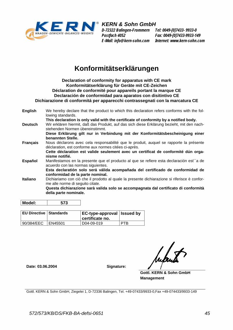
Model: 573 EU Directive Standards EC-type-approval
certificate no. Issued by
90/384/EEC EN45501 D04-09-019 PTB
Date: 03.06.2004
Signature:
Gottl. KERN & Sohn GmbH Management
Gottl. KERN & Sohn GmbH, Ziegelei 1, D-72336 Balingen, Tel. +49-07433/9933-0,Fax +49-074433/9933-149