keck adaptive optics note 218 keck adaptive optics status ... · system commissioning, ... cara)...
TRANSCRIPT
1
Keck Adaptive Optics Note 218 Keck Adaptive Optics Status and Discussion of Future Directions
Prepared for the Adaptive Optics Working Group
Peter Wizinowich & David Le Mignant for the Keck AO Team May 9, 2002 (revised June 3, 2002)
Table of Contents
1. Introduction 1.1. Purpose and Philosophy of Document 1.2. Overview of AO Facilities 1.3. Performance Summary versus Requirements 1.4. Overview of AO Operations 1.5. The Future
2. Science 2.1. Instruments 2.2. Publications 2.3. Discussion
3. Operations 3.1. Overview of AO Operations on Keck I and II 3.2. Operating the System for Science 3.3. Observing Procedures 3.4. Operations Issues 3.5. Documentation, Fault Recovery, Maintenance & Spares
4. AO NGS Facilities 4.1. Overview 4.2. Control Loops
5. AO LGS System 5.1. Laser 5.2. LGS AO Tools 5.3. Laser Safety Systems
6. Future Directions 6.1. Strehl 6.2. Sky Coverage 6.3. Emissivity and Throughput 6.4. Operations 6.5. Science Capabilities 6.6. Performance Characterization and Modeling
7. Program Management 7.1. Organization 7.2. Personnel 7.3. Budget 7.4. Schedule
8. Appendices 8.1. Refereed Keck AO Science Papers 8.2. Overview of the AO Bench Components 8.3. Performance Characterization 8.4. Keck AO Notes List 8.5. Keck AO Error Budget
Revision History: June 3, 2002: Modified section 1.3 & added appendix 8.5. Added items 13, 27 & 28 to section 6.
2
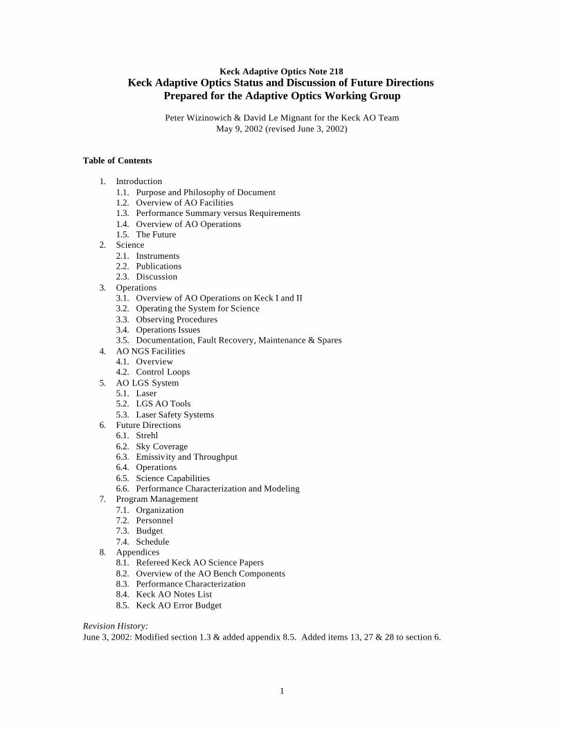
1. Introduction 1.1 Purpose and Philosophy of Document The Keck Adaptive Optics (AO) Working Group (WG) is in the process of being established. The purpose of this document is to bring this group up to a common understanding of the current status of the Keck AO Facilities. We apologize in advance for the length of this document and at the same time for errors, including errors of omission and incompleteness, in this document. There is a lot of material to cover and we hope that this document will serve as a useful starting point for the AOWG. 1.2 Overview of AO Facilities The Keck AO facilities consist of two, essentially identical, Natural Guide Star (NGS) AO systems on the left Nasmyth platforms of the twin Keck telescopes (Figure 1). The Keck II (K2) AO system has been operated for science with the NIRSPEC and NIRC2 science instruments. Only a simple engineering camera, KCAM, is available with the K1 AO system. The two AO systems have been operated simultaneously as part of the Keck Interferometer (IF).
Figure 1. Left: The AO enclosure on the left Nasmyth platform of the Keck II telescope. Right: A schematic view of the AO enclosure with its roof removed.
The first Keck AO system, the K2 AO system, was designed from the start to be used with a laser. The laser is currently mounted on the telescope and had its first light projection in Dec./01. However, the Laser Guide Star (LGS) AO tools are still being developed for completion in Sept./02, with integration of the LGS AO system on the telescope as our highest priority in FY03. We hope to begin shared risk LGS science in semester 03B. 1.3 Performance Summary versus Requirements The Keck AO systems are capable of achieving Strehl ratios of 0.5 at H-band under good seeing conditions with a V < 7 magnitude star. Under median seeing conditions we typically achieve a Strehl of 0.3 for V< 10. This performance is poorer than the design requirement (see KOR 208) prediction of Strehl = 0.79
NIRC2 Or
KCAM
NIRSPEC
Telescope Elevation
Ring
Electronics Room
3
under excellent conditions, and 0.64 under median conditions. Our best H-band images have a FWHM of 38 to 40 milli-arcsec compared to the diffraction-limit of 34 milli-arcsec. The requirement and error budget are discussed in Appendix 8.5. The error budget presented in this Appendix predicts a best H-band Strehl of 0.48 with an average Strehl of 0.33 for bright stars, which is reasonably consistent with the observed values. The limiting magnitude where the AO system is no longer able to close the loops occurs between a V-magnitude of 13 and 14. We can close the tip/tilt loop on stars as faint as V = 14. Some detailed performance data can be found in Appendix 8.3. 1.4 Overview of AO Operations The K2 AO system has been operated for 30 to 40 science nights per 6-month semester since semester 2000A. Initial operations required an AO expert. The K2 AO system is now operated by the Observing Assistant (OA), with an AO expert on-call. Both NIRSPEC and NIRC2 are routinely scheduled for science with K2 AO. We are now at a fairly mature level of K2 AO science operation, although there is still room for improvement. Both AO systems are now routinely used for interferometer engineering observing. 1.5 The Future As part of the FY03 planning process the AO team has defined a number of potential projects for improving the AO system and its capabilities. Currently our major project is completing the K2 LGS AO system commissioning, while continuing to support AO science observing. We define these proposed projects in section 6 to provide the AOWG with some insight into our thinking. 2. Science 2.1 Instruments Table 1 provides a summary of the current and planned Keck AO science instruments.
Table 1. Science Instruments Name Date of 1st
AO Light Detector
(# pixels & type) Plate Scale (arcsec/pixel)
Spectral Resolution
Notes
KCAM (UCLA) Feb., 1999 256x256 NICMOS3 (HgCdTe)
0.017 N/a Focus stage; 12-position external filter wheel; J,H,K’ internal filters
Feb., 2000 for spectra
1024x1024 InSb
0.0185 high R 0.013 low R
Low=2000 High=27000
NIRSPEC (UCLA)
Apr., 2000 for imaging
256x256 PICNIC for slit viewing
0.017 N/a
10.6 magnification provided by 2 spherical mirrors on AO bench; 12-position
external filter wheel Interferometer (JPL, CARA)
Mar., 2001 Hawaii AO on both Kecks
NIRC2 (Caltech)
July, 2001 1024x1024 InSb 0.01, 0.02 & 0.04
~5000 with grisms
Designed for AO system
OSIRIS (UCLA )
2005A OH-Suppression IR Integral field Spectrograph
AO Acquisition Camera
Apr., 1999 1024x1024 CCD Photometrics PXL
0.0075 high R 0.134 normal
N/a Only tried once in high res. Potential visible science camera
2.2 Publications A total of 13 refereed science papers, and 3 IAU circulars, have been published using Keck AO results. A summary table of these publications can be found in Appendix 8.1. Three papers were published in 2000, 5
4
papers in 2001, and 5 papers so far in 2002. The mix of these papers is 2 planetary, 8 galactic and 2 extra-galactic. A bibliography of refereed AO science papers is maintained at http://www2.keck.hawaii.edu:3636/realpublic/inst/ao/ao_sci_list.html. 2.3 Discussion We are somewhat disappointed in the number of science publications so far achieved with the Keck AO facility. It would be useful to understand the reason for this limited publication rate. For example, from our 1999 engineering science verification observing program the only results that have been published so far are the faint galaxy observations and a binary system. The observations of the galactic center, Neptune, Vesta and two Seyfert galaxies have not been published, and only the Neptune data is likely to be published. Some potential explanations for this apparently low rate of publication:
• We were extremely limited initially by our first light science instrument, KCAM. • Our observing efficiency was low initially. • The AO system was not capable of performing some of the science being tried. For example, the
performance when Seyfert galaxies are used as the guide star is borderline. • AO performance is more dependent on seeing conditions and wind shake. Observers may not
have had a useful backup program for these conditions. • AO observing, and even IR observing, may be new to some observers
o Initial observers may not have taken all of the data they needed to properly reduce their science data.
o Some observers may not have had the tools they needed to reduce their science data. • Some observers are too busy to publish their data in a timely manner.
3. Operations The purpose of this section is to present how the Adaptive Optics system is operated during science observing. 3.1 Overview of AO operations on Keck I and Keck II To allow the Keck staff to operate the AO system in science mode, the AO team and the software team have developed various software tools that differ from the AO engineering software. These include a (Graphical) User Interface and automated scripts used for setup, calibration, acquisition and troubleshooting. The Keck AO system is a complex system working with various instruments in science mode. Note that even for the experts, it is difficult to step manually through the WFS calibrations without documentation. Such a complex system should be operated under configuration control whoever the user. This has become a requirement for science operation during system setup, calibrations and observing. Following these ideas, we targeted the following Keck AO team priorities:
• User-friendly access to the AO tools • Higher reliability of the AO tools (hardware and software) • Keck staff training for AO science • AO operations in a very controlled environment
As an example, the software team has been working on increasing the reliability of the AO tools and implementing easier access to these tools. At the same time, the AO team has been concentrating on the development of IDL routines that automatically:
• configure the AO system for calibrations and/or night time observing, • calibrate the AO system depending on the instrument and telescope,
5
• set and optimize the AO system optics and WFC parameters for the observed target, given its brightness and color,
• handle FSM pointing reference depending on instrument, • detect and fixed faulted devices on the Optics Bench, • halt the AO system
3.2 Operating the system for science During science nights, the following operation scheme has been in use for more than a year:
• The Support Astronomer (SA) introduces the visiting astronomer to the operation of the NIR camera in the afternoon. The visiting astronomer and the SA review the observing plan and investigate any issues (either instrument or AO related). The SA is usually present for the first half of the night and remains on-call otherwise.
• The Observing Assistant (OA), located at the summit, is responsible for the telescope and its
subsystems (Drive Control System, Active Control System, dome, meteorology, etc.). The OA also operates the adaptive optics system.
• Once the telescope is pointing to the target and the AO loops closed on the AO guide star, the
visiting astronomer is in charge of recording the science data. The astronomer configures the near-infrared camera (NIRSPAO or NIRC2) for the target and integrates on the target. Both Nirspao and Nirc2 observing software include a set of dithering scripts. During observing, opening/closing AO loops and moving Field Steering Mirror are automated and synchronized with telescope moves. For most observing schemes, the AO system operations remain "transparent" to the astronomer.
• The AO Support person calibrates the AO system in the afternoon. He stays in contact with the
observers for the first part of the night, making sure that the AO systems works optimally for the given atmospheric conditions. The AO support is on-call for any AO night.
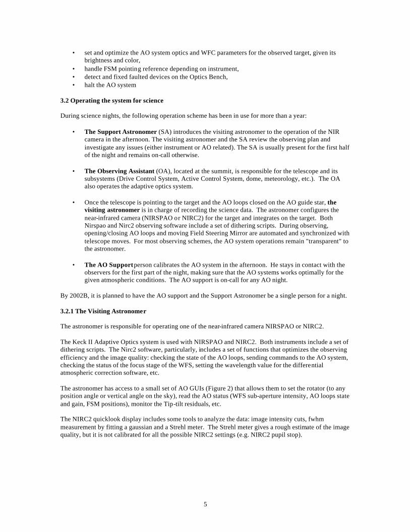
By 2002B, it is planned to have the AO support and the Support Astronomer be a single person for a night. 3.2.1 The Visiting Astronomer The astronomer is responsible for operating one of the near-infrared camera NIRSPAO or NIRC2. The Keck II Adaptive Optics system is used with NIRSPAO and NIRC2. Both instruments include a set of dithering scripts. The Nirc2 software, particularly, includes a set of functions that optimizes the observing efficiency and the image quality: checking the state of the AO loops, sending commands to the AO system, checking the status of the focus stage of the WFS, setting the wavelength value for the differential atmospheric correction software, etc. The astronomer has access to a small set of AO GUIs (Figure 2) that allows them to set the rotator (to any position angle or vertical angle on the sky), read the AO status (WFS sub-aperture intensity, AO loops state and gain, FSM positions), monitor the Tip-tilt residuals, etc. The NIRC2 quicklook display includes some tools to analyze the data: image intensity cuts, fwhm measurement by fitting a gaussian and a Strehl meter. The Strehl meter gives a rough estimate of the image quality, but it is not calibrated for all the possible NIRC2 settings (e.g. NIRC2 pupil stop).
6
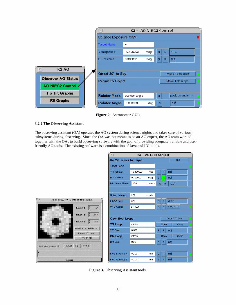
Figure 2. Astronomer GUIs 3.2.2 The Observing Assistant The observing assistant (OA) operates the AO system during science nights and takes care of various subsystems during observing. Since the OA was not meant to be an AO expert, the AO team worked together with the OAs to build observing software with the goal of providing adequate, reliable and user-friendly AO tools. The existing software is a combination of Java and IDL tools.
Figure 3. Observing Assistant tools.
7
The Java User Interfaces (UI) displays the state of the system (Figure 3 left) and includes a set of automation units to send commands to move devices and monitor their state. The automation units included in the Java interface do more complicated operation like setting the AO bench rotator depending on the instrument in use and the telescope pointing direction. The IDL software includes widgets, functions and scripts with more built-in complexity to acquire a target, adjust the Field Steering Mirrors (FSM) pointing, adjust the WFS settings, display the WFS intensity map (Figure 3 right), configures the AO system for observing, auto-recover from faulted stages, etc. The observing assistants monitor the AO performance by referring to:
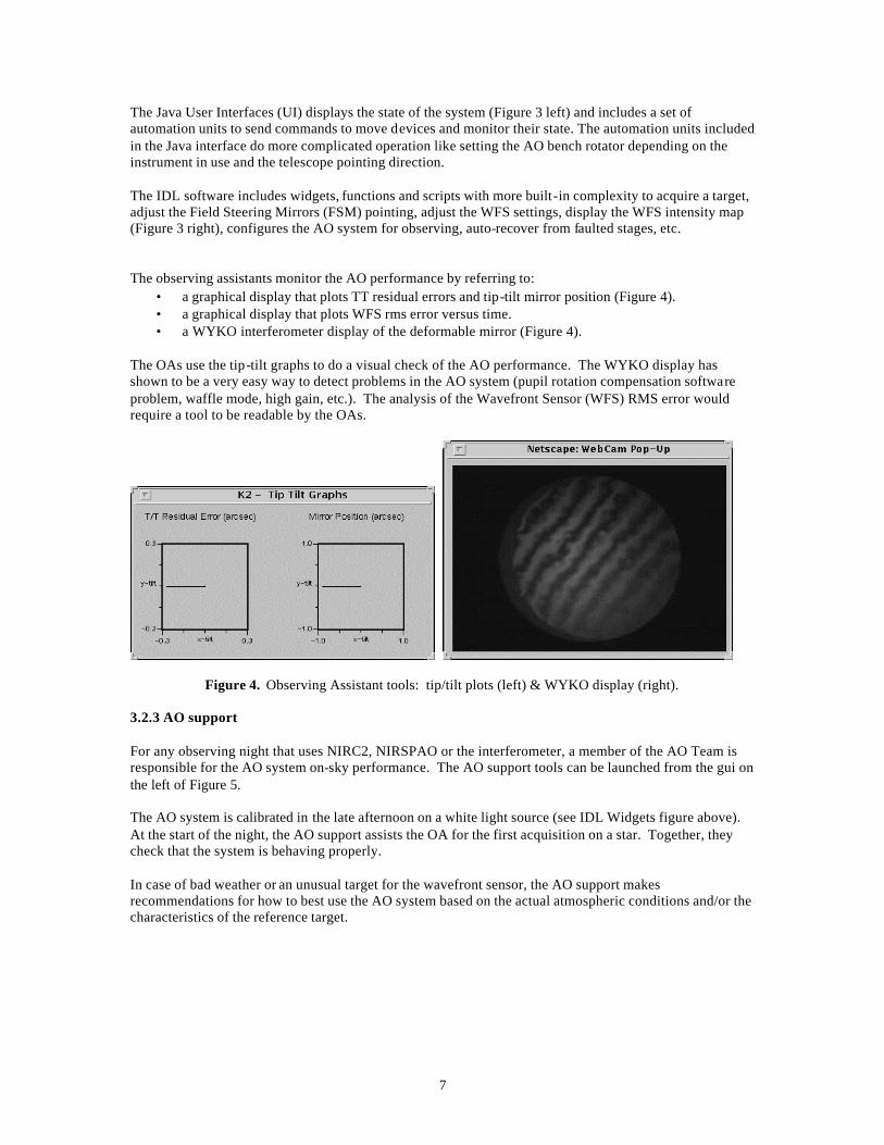
• a graphical display that plots TT residual errors and tip-tilt mirror position (Figure 4). • a graphical display that plots WFS rms error versus time. • a WYKO interferometer display of the deformable mirror (Figure 4).
The OAs use the tip-tilt graphs to do a visual check of the AO performance. The WYKO display has shown to be a very easy way to detect problems in the AO system (pupil rotation compensation software problem, waffle mode, high gain, etc.). The analysis of the Wavefront Sensor (WFS) RMS error would require a tool to be readable by the OAs.
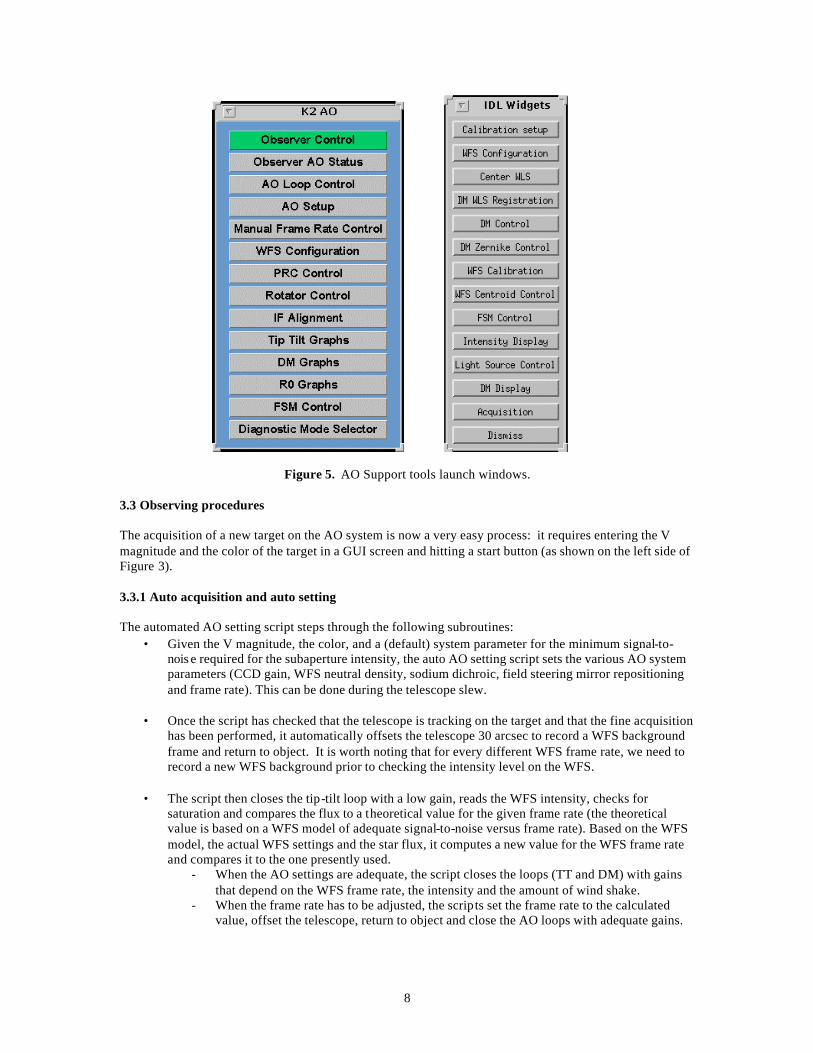
Figure 4. Observing Assistant tools: tip/tilt plots (left) & WYKO display (right). 3.2.3 AO support For any observing night that uses NIRC2, NIRSPAO or the interferometer, a member of the AO Team is responsible for the AO system on-sky performance. The AO support tools can be launched from the gui on the left of Figure 5. The AO system is calibrated in the late afternoon on a white light source (see IDL Widgets figure above). At the start of the night, the AO support assists the OA for the first acquisition on a star. Together, they check that the system is behaving properly. In case of bad weather or an unusual target for the wavefront sensor, the AO support makes recommendations for how to best use the AO system based on the actual atmospheric conditions and/or the characteristics of the reference target.
8
Figure 5. AO Support tools launch windows. 3.3 Observing procedures The acquisition of a new target on the AO system is now a very easy process: it requires entering the V magnitude and the color of the target in a GUI screen and hitting a start button (as shown on the left side of Figure 3). 3.3.1 Auto acquisition and auto setting The automated AO setting script steps through the following subroutines:
• Given the V magnitude, the color, and a (default) system parameter for the minimum signal-to-nois e required for the subaperture intensity, the auto AO setting script sets the various AO system parameters (CCD gain, WFS neutral density, sodium dichroic, field steering mirror repositioning and frame rate). This can be done during the telescope slew.
• Once the script has checked that the telescope is tracking on the target and that the fine acquisition
has been performed, it automatically offsets the telescope 30 arcsec to record a WFS background frame and return to object. It is worth noting that for every different WFS frame rate, we need to record a new WFS background prior to checking the intensity level on the WFS.
• The script then closes the tip-tilt loop with a low gain, reads the WFS intensity, checks for
saturation and compares the flux to a theoretical value for the given frame rate (the theoretical value is based on a WFS model of adequate signal-to-noise versus frame rate). Based on the WFS model, the actual WFS settings and the star flux, it computes a new value for the WFS frame rate and compares it to the one presently used.
- When the AO settings are adequate, the script closes the loops (TT and DM) with gains that depend on the WFS frame rate, the intensity and the amount of wind shake.
- When the frame rate has to be adjusted, the scripts set the frame rate to the calculated value, offset the telescope, return to object and close the AO loops with adequate gains.
9
The duration of the AO acquisition and AO setting procedure varies between 35 to 90 sec. When the intensity counts on the WFS do not correspond to the expected brightness (perhaps brighter or fainter due to clouds or an error in the V magnitude value set for the target) the script will take longer but will finally converge to the correct settings for the star. 3.3.2 Other obs erving scripts Other observing scripts include:
• Managing and setting the FSM positions at acquisition so that the star falls at any desired position on the NIR array (center of a quadrant, onto a slit or behind an occulting mask),.
• Detecting any FSM or rotator fault and fixing it automatically. • Fixing any problem between the AO and DCS by a proper re-initalization of the communications.
3.4 Operation issues The main science operation issue with the present state of the AO systems is related to its performance. This may be expressed by the following assumptions:
• We haven’t achieved a complete characterization of the AO system and its subsystems. Hence we miss a clear understanding of the error budget contribution from the WFS optics, from the noise propagation, etc.
• The present design of the wavefront controller does not allow us to implement the tools needed to optimize the AO system and run it at its best performance.
The complete characterization of the AO system has not been achieved because the priority was given to science observing. Over the last two years, the AO Team has concentrated on getting the two AO systems on-line and getting them up to a point where they can be operated by the Observing Assistant. Since the AO team resources were concentrated on these tasks, plus providing support for AO science (30 to 40 nights a semester), we were only able to carry on with a limited number of tasks related to the characterization of the system. We have identified various sources of errors:
• The WFS camera has a dark current of 2000 e-/sec for K2AO and ~ 900 e-/sec for K1AO. • The WFS background intensity has been reduced by a factor 5. The light contamination was
coming from inside the AO enclosure, from the encoders on the optics bench. • We have been trying to study the performance of the AO system as a function of TT and DM
gains. We realized that the performance remains at the same level for a wide range of gains. We observed an under-sensitivity of the system gains.
• Through collaboration with Matthias Schoeck (CfAO/UCI), we have measured the spot size on the WFS quad-cell. The preliminary results indicate that the spot size is a factor 4 larger than what it should be. We are presently working on this issue as this would partly explain the system gain problem.
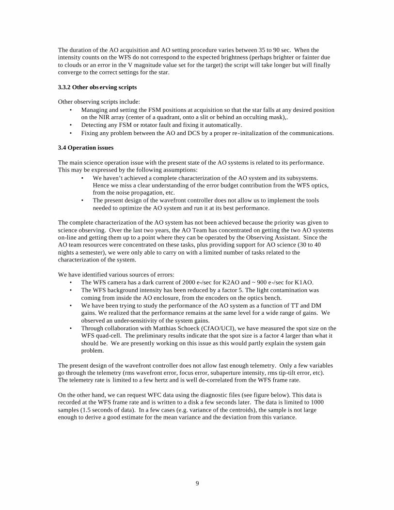
The present design of the wavefront controller does not allow fast enough telemetry. Only a few variables go through the telemetry (rms wavefront error, focus error, subaperture intensity, rms tip-tilt error, etc). The telemetry rate is limited to a few hertz and is well de-correlated from the WFS frame rate. On the other hand, we can request WFC data using the diagnostic files (see figure below). This data is recorded at the WFS frame rate and is written to a disk a few seconds later. The data is limited to 1000 samples (1.5 seconds of data). In a few cases (e.g. variance of the centroids), the sample is not large enough to derive a good estimate for the mean variance and the deviation from this variance.
10
Figure 6. Diagnostic mode selector tool. We hope that the EPICS upgrade of the WFC will provide an opportunity to increase the telemetry rate. To increase the number of sample of data inside the diagnostic files, it will be necessary to upgrade the memory on the WFC mercury board. We also face another problem: we are missing good documentation of the diagnostics and telemetry modes that have been implemented. For example, the units for the Zernike errors measured by the WFS that we can request through the diagnostic files are not understood. The same happens with the rms wavefront error and the DM Zernike errors. For most of these modes, we need reverse engineering to find out from the WFC code what the calculation is doing and what the units are. With the arrival of new members in the AO team, we are now starting along this process and we hope to get a better understanding of the WFC telemetry and diagnostic modes. 3.5 Documentation, fault recovery, maintenance & spares The majority of our documentation can be found on the KeckShare internal web site, including our series of Keck Adaptive Optics Notes (see Appendix 8.4 for a summary list), mechanical and electronics drawings, subsystem manuals, vendor manuals and performance data. Procedures for starting and calibrating the AO systems can be found on the optics internal web page. Observer information for AO can be found on the public instrument web page at http://www2.keck.hawaii.edu:3636/realpublic/inst/. Some fault recovery procedures exist. Electronics spares are controlled via the electronics group database. 4. AO NGS Facilities 4.1 Overview The NGS AO facility is located on the left Nasmyth platform of the Keck II telescope at the f/15 focus. The entire facility is enclosed in the thermally insulated enclosure shown in Figure 1. The enclosure is divided into two rooms, one for the AO bench and science instruments and the other for the electronics racks. The electronics room contains an air to glycol heat exchanger to remove heat from the telescope.
The NGS AO facility consists of multiple subsystems that communicate over an ethernet connection using EPICS (Experimental Physics and Industrial Control System). These subsystems include the optics bench subsystem, wavefront controller subsystem, supervisory controller subsystem and user interface. With the exception of the user interface and acquisition camera servers, which run on Sun/Unix machines, all of the subsystem computers are mounted in two VME crates. There are two electronics racks for the optics bench subsystem, one for the wavefront controller and one for the deformable mirror.
11
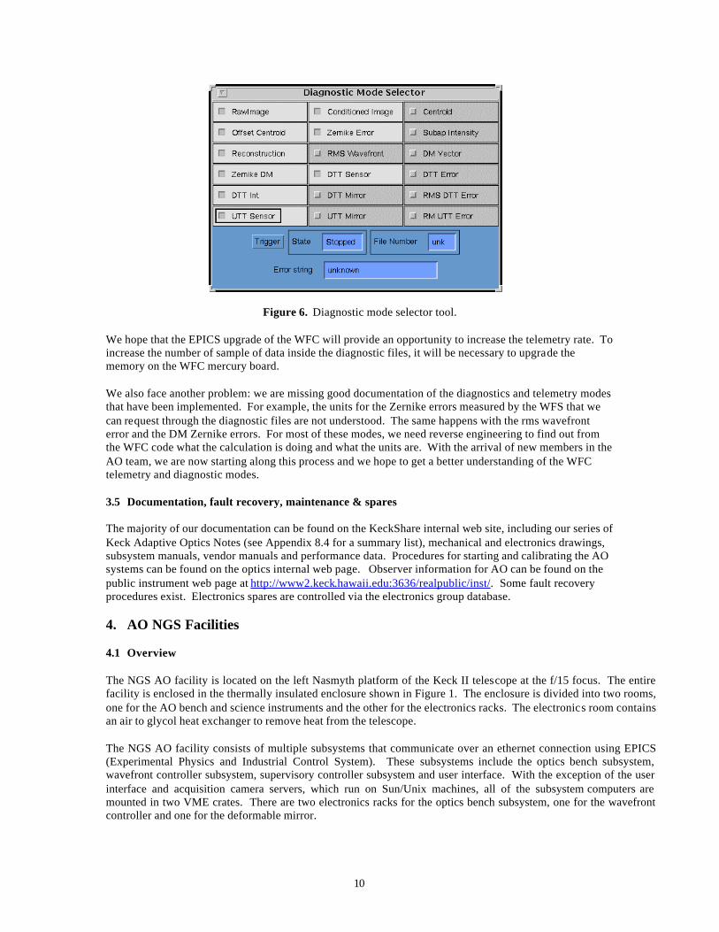
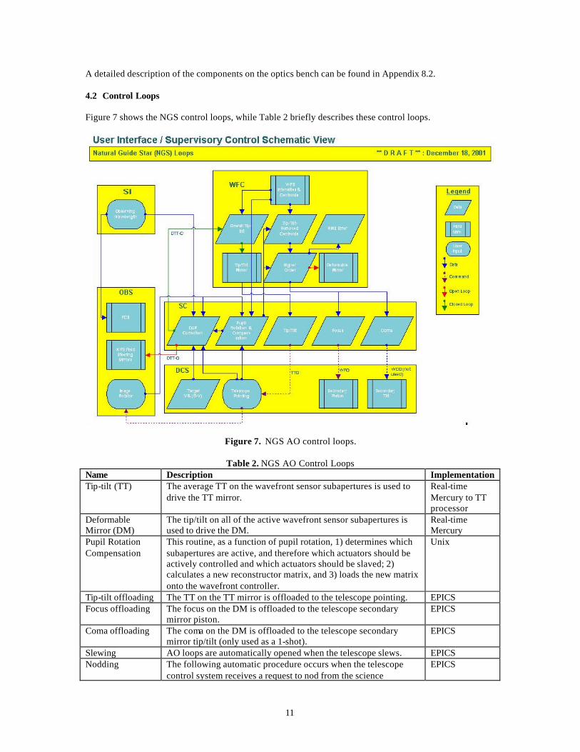
A detailed description of the components on the optics bench can be found in Appendix 8.2. 4.2 Control Loops Figure 7 shows the NGS control loops, while Table 2 briefly describes these control loops.
Figure 7. NGS AO control loops.
Table 2. NGS AO Control Loops Name Description Implementation Tip-tilt (TT) The average TT on the wavefront sensor subapertures is used to
drive the TT mirror. Real-time Mercury to TT processor
Deformable Mirror (DM)
The tip/tilt on all of the active wavefront sensor subapertures is used to drive the DM.
Real-time Mercury
Pupil Rotation Compensation
This routine, as a function of pupil rotation, 1) determines which subapertures are active, and therefore which actuators should be actively controlled and which actuators should be slaved; 2) calculates a new reconstructor matrix, and 3) loads the new matrix onto the wavefront controller.
Unix
Tip-tilt offloading The TT on the TT mirror is offloaded to the telescope pointing. EPICS Focus offloading The focus on the DM is offloaded to the telescope secondary
mirror piston. EPICS
Coma offloading The coma on the DM is offloaded to the telescope secondary mirror tip/tilt (only used as a 1-shot).
EPICS
Slewing AO loops are automatically opened when the telescope slews. EPICS Nodding The following automatic procedure occurs when the telescope
control system receives a request to nod from the science EPICS
12
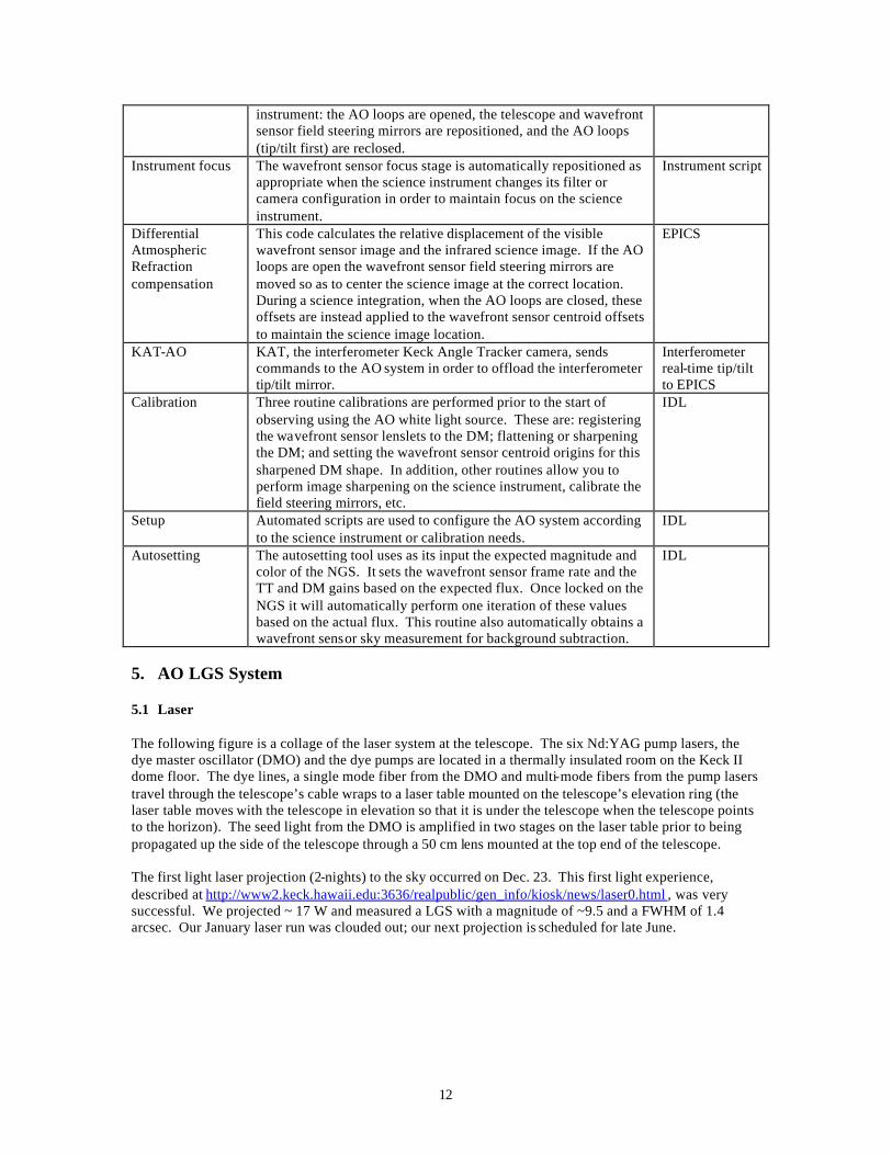
instrument: the AO loops are opened, the telescope and wavefront sensor field steering mirrors are repositioned, and the AO loops (tip/tilt first) are reclosed.
Instrument focus The wavefront sensor focus stage is automatically repositioned as appropriate when the science instrument changes its filter or camera configuration in order to maintain focus on the science instrument.
Instrument script
Differential Atmospheric Refraction compensation
This code calculates the relative displacement of the visible wavefront sensor image and the infrared science image. If the AO loops are open the wavefront sensor field steering mirrors are moved so as to center the science image at the correct location. During a science integration, when the AO loops are closed, these offsets are instead applied to the wavefront sensor centroid offsets to maintain the science image location.
EPICS
KAT-AO KAT, the interferometer Keck Angle Tracker camera, sends commands to the AO system in order to offload the interferometer tip/tilt mirror.
Interferometer real-time tip/tilt to EPICS
Calibration Three routine calibrations are performed prior to the start of observing using the AO white light source. These are: registering the wavefront sensor lenslets to the DM; flattening or sharpening the DM; and setting the wavefront sensor centroid origins for this sharpened DM shape. In addition, other routines allow you to perform image sharpening on the science instrument, calibrate the field steering mirrors, etc.
IDL
Setup Automated scripts are used to configure the AO system according to the science instrument or calibration needs.
IDL
Autosetting The autosetting tool uses as its input the expected magnitude and color of the NGS. It sets the wavefront sensor frame rate and the TT and DM gains based on the expected flux. Once locked on the NGS it will automatically perform one iteration of these values based on the actual flux. This routine also automatically obtains a wavefront sensor sky measurement for background subtraction.
IDL
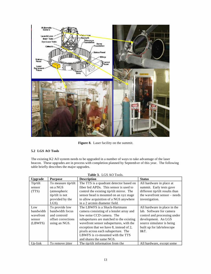
5. AO LGS System 5.1 Laser The following figure is a collage of the laser system at the telescope. The six Nd:YAG pump lasers, the dye master oscillator (DMO) and the dye pumps are located in a thermally insulated room on the Keck II dome floor. The dye lines, a single mode fiber from the DMO and multi-mode fibers from the pump lasers travel through the telescope’s cable wraps to a laser table mounted on the telescope’s elevation ring (the laser table moves with the telescope in elevation so that it is under the telescope when the telescope points to the horizon). The seed light from the DMO is amplified in two stages on the laser table prior to being propagated up the side of the telescope through a 50 cm lens mounted at the top end of the telescope. The first light laser projection (2-nights) to the sky occurred on Dec. 23. This first light experience, described at http://www2.keck.hawaii.edu:3636/realpublic/gen_info/kiosk/news/laser0.html , was very successful. We projected ~ 17 W and measured a LGS with a magnitude of ~9.5 and a FWHM of 1.4 arcsec. Our January laser run was clouded out; our next projection is scheduled for late June.
13
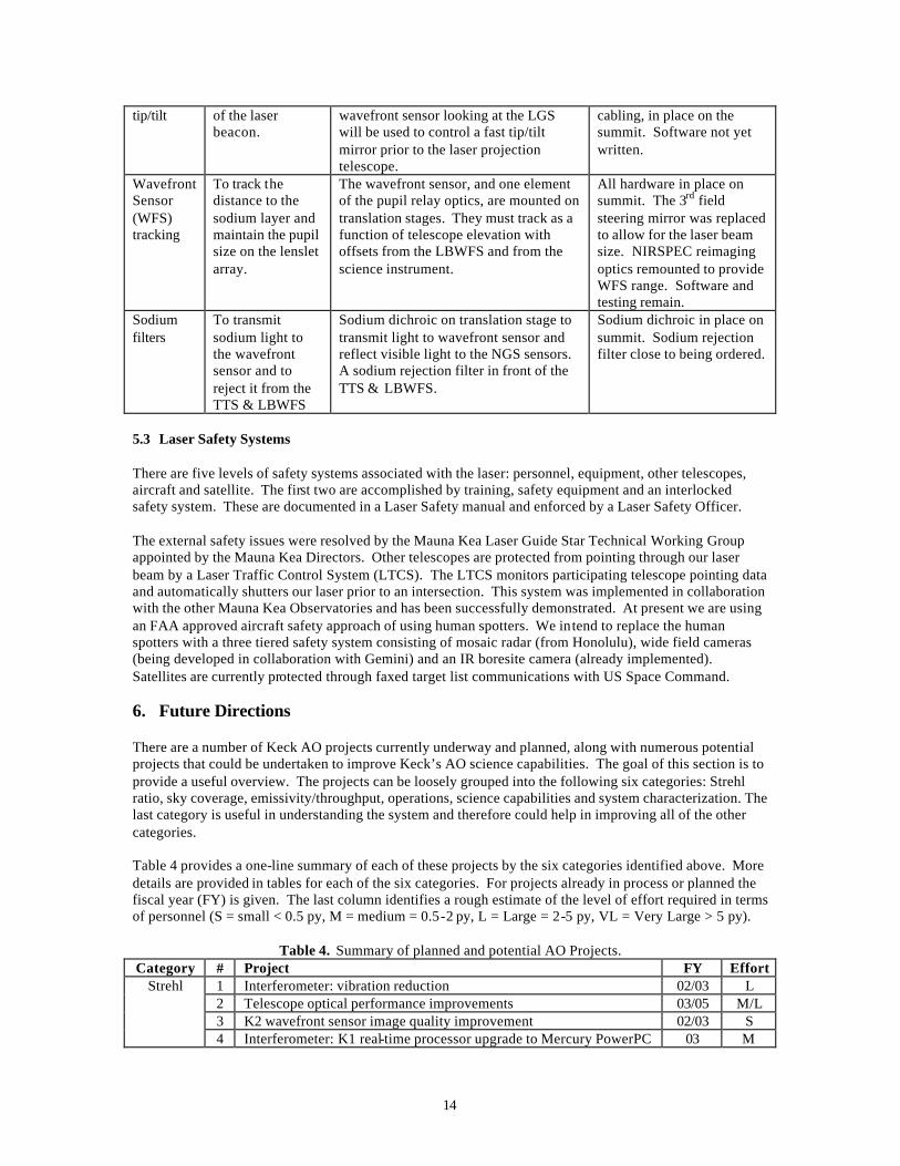
Figure 8. Laser facility on the summit. 5.2 LGS AO Tools The existing K2 AO system needs to be upgraded in a number of ways to take advantage of the laser beacon. These upgrades are in process with completion planned by Septemb er of this year. The following table briefly describes the major upgrades.
Table 3. LGS AO Tools. Upgrade Purpose Description Status Tip/tilt sensor (TTS)
To measure tip/tilt on a NGS (atmospheric tip/tilt is not provided by the LGS).
The TTS is a quadrant detector based on fiber fed APDs. This sensor is used to control the existing tip/tilt mirror. The sensor head is mounted on an xyz stage to allow acquisition of a NGS anywhere in a 2 arcmin diameter field.
All hardware in place at summit. Early tests gave different tip/tilt results than the wavefront sensor – needs investigation.
Low bandwidth wavefront sensor (LBWFS)
To provide low bandwidth focus and centroid offset corrections using an NGS.
The LBWFS is a Shack-Hartmann camera consisting of a lenslet array and low noise CCD camera. The subapertures are matched to the existing wavefront sensor subapertures, with the exception that we have 8, instead of 2, pixels across each subaperture. The LBWFS is co-mounted with the TTS and shares the same NGS.
All hardware in place in the lab. Software for camera control and processing under development. An LGS source simulator is being built up for lab/telescope I&T.
Up-link To remove jitter The tip/tilt information from the All hardware, except some
14
tip/tilt of the laser beacon.
wavefront sensor looking at the LGS will be used to control a fast tip/tilt mirror prior to the laser projection telescope.
cabling, in place on the summit. Software not yet written.
Wavefront Sensor (WFS) tracking
To track the distance to the sodium layer and maintain the pupil size on the lenslet array.
The wavefront sensor, and one element of the pupil relay optics, are mounted on translation stages. They must track as a function of telescope elevation with offsets from the LBWFS and from the science instrument.
All hardware in place on summit. The 3rd field steering mirror was replaced to allow for the laser beam size. NIRSPEC reimaging optics remounted to provide WFS range. Software and testing remain.
Sodium filters
To transmit sodium light to the wavefront sensor and to reject it from the TTS & LBWFS
Sodium dichroic on translation stage to transmit light to wavefront sensor and reflect visible light to the NGS sensors. A sodium rejection filter in front of the TTS & LBWFS.
Sodium dichroic in place on summit. Sodium rejection filter close to being ordered.
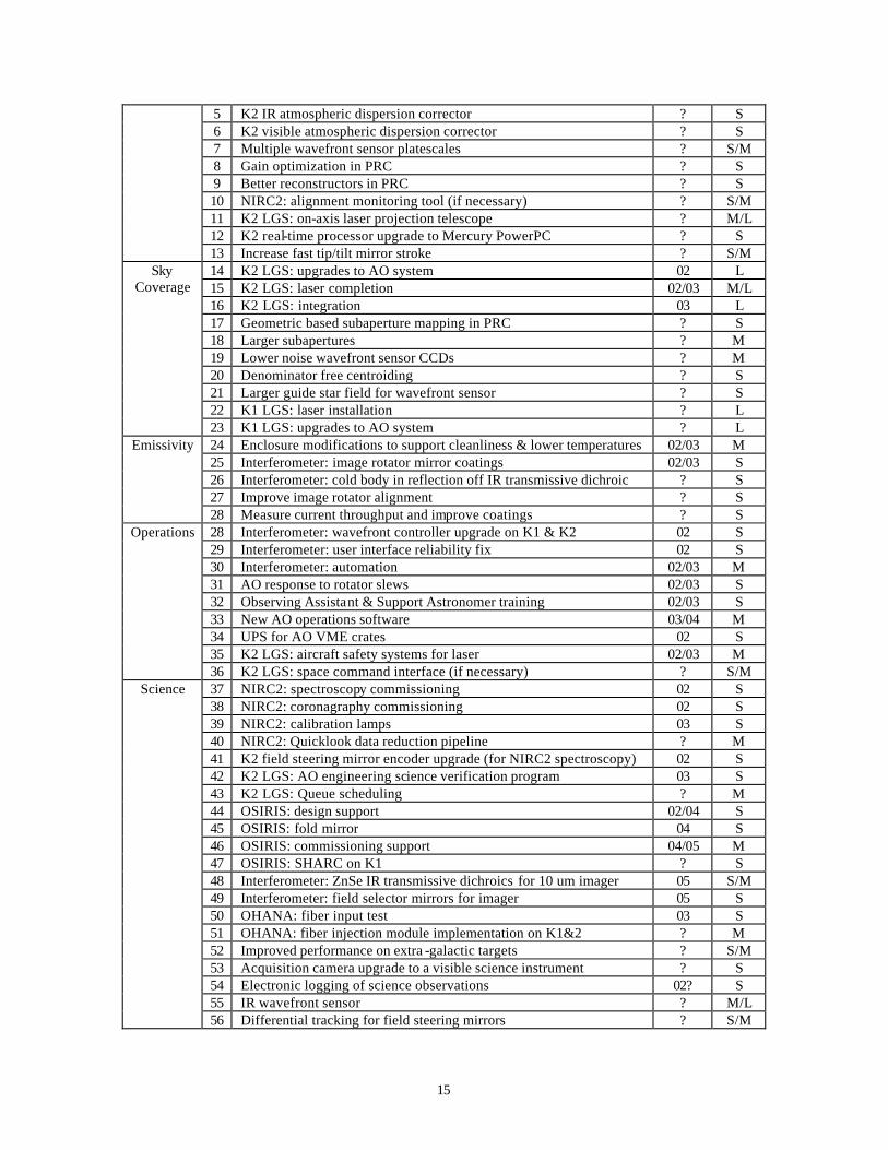
5.3 Laser Safety Systems There are five levels of safety systems associated with the laser: personnel, equipment, other telescopes, aircraft and satellite. The first two are accomplished by training, safety equipment and an interlocked safety system. These are documented in a Laser Safety manual and enforced by a Laser Safety Officer. The external safety issues were resolved by the Mauna Kea Laser Guide Star Technical Working Group appointed by the Mauna Kea Directors. Other telescopes are protected from pointing through our laser beam by a Laser Traffic Control System (LTCS). The LTCS monitors participating telescope pointing data and automatically shutters our laser prior to an intersection. This system was implemented in collaboration with the other Mauna Kea Observatories and has been successfully demonstrated. At present we are using an FAA approved aircraft safety approach of using human spotters. We intend to replace the human spotters with a three tiered safety system consisting of mosaic radar (from Honolulu), wide field cameras (being developed in collaboration with Gemini) and an IR boresite camera (already implemented). Satellites are currently protected through faxed target list communications with US Space Command. 6. Future Directions There are a number of Keck AO projects currently underway and planned, along with numerous potential projects that could be undertaken to improve Keck’s AO science capabilities. The goal of this section is to provide a useful overview. The projects can be loosely grouped into the following six categories: Strehl ratio, sky coverage, emissivity/throughput, operations, science capabilities and system characterization. The last category is useful in understanding the system and therefore could help in improving all of the other categories. Table 4 provides a one-line summary of each of these projects by the six categories identified above. More details are provided in tables for each of the six categories. For projects already in process or planned the fiscal year (FY) is given. The last column identifies a rough estimate of the level of effort required in terms of personnel (S = small < 0.5 py, M = medium = 0.5-2 py, L = Large = 2-5 py, VL = Very Large > 5 py).
Table 4. Summary of planned and potential AO Projects. Category # Project FY Effort
1 Interferometer: vibration reduction 02/03 L 2 Telescope optical performance improvements 03/05 M/L 3 K2 wavefront sensor image quality improvement 02/03 S
Strehl
4 Interferometer: K1 real-time processor upgrade to Mercury PowerPC 03 M
15
5 K2 IR atmospheric dispersion corrector ? S 6 K2 visible atmospheric dispersion corrector ? S 7 Multiple wavefront sensor platescales ? S/M 8 Gain optimization in PRC ? S 9 Better reconstructors in PRC ? S 10 NIRC2: alignment monitoring tool (if necessary) ? S/M 11 K2 LGS: on-axis laser projection telescope ? M/L 12 K2 real-time processor upgrade to Mercury PowerPC ? S
13 Increase fast tip/tilt mirror stroke ? S/M 14 K2 LGS: upgrades to AO system 02 L 15 K2 LGS: laser completion 02/03 M/L 16 K2 LGS: integration 03 L 17 Geometric based subaperture mapping in PRC ? S 18 Larger subapertures ? M 19 Lower noise wavefront sensor CCDs ? M 20 Denominator free centroiding ? S 21 Larger guide star field for wavefront sensor ? S 22 K1 LGS: laser installation ? L
Sky Coverage
23 K1 LGS: upgrades to AO system ? L 24 Enclosure modifications to support cleanliness & lower temperatures 02/03 M 25 Interferometer: image rotator mirror coatings 02/03 S 26 Interferometer: cold body in reflection off IR transmissive dichroic ? S 27 Improve image rotator alignment ? S
Emissivity
28 Measure current throughput and improve coatings ? S 28 Interferometer: wavefront controller upgrade on K1 & K2 02 S 29 Interferometer: user interface reliability fix 02 S 30 Interferometer: automation 02/03 M 31 AO response to rotator slews 02/03 S 32 Observing Assistant & Support Astronomer training 02/03 S 33 New AO operations software 03/04 M 34 UPS for AO VME crates 02 S 35 K2 LGS: aircraft safety systems for laser 02/03 M
Operations
36 K2 LGS: space command interface (if necessary) ? S/M 37 NIRC2: spectroscopy commissioning 02 S 38 NIRC2: coronagraphy commissioning 02 S 39 NIRC2: calibration lamps 03 S 40 NIRC2: Quicklook data reduction pipeline ? M 41 K2 field steering mirror encoder upgrade (for NIRC2 spectroscopy) 02 S 42 K2 LGS: AO engineering science verification program 03 S 43 K2 LGS: Queue scheduling ? M 44 OSIRIS: design support 02/04 S 45 OSIRIS: fold mirror 04 S 46 OSIRIS: commissioning support 04/05 M 47 OSIRIS: SHARC on K1 ? S 48 Interferometer: ZnSe IR transmissive dichroics for 10 um imager 05 S/M 49 Interferometer: field selector mirrors for imager 05 S 50 OHANA: fiber input test 03 S 51 OHANA: fiber injection module implementation on K1&2 ? M 52 Improved performance on extra -galactic targets ? S/M 53 Acquisition camera upgrade to a visible science instrument ? S 54 Electronic logging of science observations 02? S 55 IR wavefront sensor ? M/L
Science
56 Differential tracking for field steering mirrors ? S/M
16
57 Next generation Keck AO CoDR ? L 58 Next generation Keck AO PDR, CDR, fab, I&T, commissioning ? VL 59 Atmospheric characterization tool 02 S 60 CfAO postdoc performance modeling & characterization effort 03/04 S/M
Character- ization
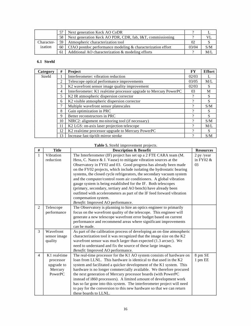
61 Additional AO characterization & modeling efforts ? M/L 6.1 Strehl Category # Project FY Effort
1 Interferometer: vibration reduction 02/03 L 2 Telescope optical performance improvements 03/05 M/L 3 K2 wavefront sensor image quality improvement 02/03 S 4 Interferometer: K1 real-time processor upgrade to Mercury PowerPC 03 M 5 K2 IR atmospheric dispersion corrector ? S 6 K2 visible atmospheric dispersion corrector ? S 7 Multiple wavefront sensor platescales ? S/M 8 Gain optimization in PRC ? S 9 Better reconstructors in PRC ? S 10 NIRC2: alignment mo nitoring tool (if necessary) ? S/M 11 K2 LGS: on-axis laser projection telescope ? M/L 12 K2 real-time processor upgrade to Mercury PowerPC ? S
Strehl
13 Increase fast tip/tilt mirror stroke ? S/M
Table 5. Strehl improvement projects. # Title Description & Benefit Resources 1 Vibration
reduction The Interferometer (IF) project has set up a 2 FTE CARA team (M. Hess, C. Nance & J. Vause) to mitigate vibration sources at the Observatory in FY02 and 03. Good progress has already been made on the FY02 projects, which include isolating the hydrostatic bearing systems, the closed cycle refrigerators, the secondary vacuum system and the computer/control room air conditioners. A global vibration gauge system is being established for the IF. Both telescopes (primary, secondary, tertiary and AO bench) have already been outfitted with accelerometers as part of the IF feed forward vibration compensation system. Benefit: Improved AO performance.
2 py /year in FY02 & 03
2 Telescope performance
The Observatory is planning to hire an optics engineer to primarily focus on the wavefront quality of the telescope. This engineer will generate a new telescope wavefront error budget based on current performance and recommend areas where significant improvements can be made.
3 Wavefront sensor image quality
As part of the calibration process of developing an on-line atmospheric characterization tool it was recognized that the image size on the K2 wavefront sensor was much larger than expected (1.3 arcsec). We need to understand and fix the source of these large images. Benefit: Improved AO performance.
4 K1 real-time processor upgrade to Mercury PowerPC
The real-time processor for the K1 AO system consists of hardware on loan from LLNL. This hardware is identical to that used in the K2 system and facilitated a quicker development of the K1 system. This hardware is no longer commercially available. We therefore procured the next generation of Mercury processor boards (with PowerPC instead of i860 processors). A limited amount of development work has so far gone into this system. The interferometer project will need to pay for the conversion to this new hardware so that we can return these boards to LLNL.
8 pm SE 1 pm EE
17
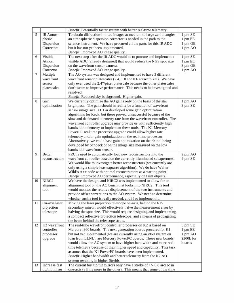
Benefit: Potentially faster system with better real-time telemetry. 5 IR Atmos-
pheric Dispersion Correctors
To obtain diffraction-limited images at medium to large zenith angles an atmospheric dispersion corrector is needed in the path to the science instrument. We have procured all the parts for this IR ADC but it has not yet been implemented. Benefit: Improved AO image quality.
1 pm SE 1 pm EE 1 pm OE 1 pm AO
6 Visible Atmos. Dispersion Corrector
The next step after the IR ADC would be to procure and implement a visible ADC (already designed) that would reduce the NGS spot size on the wavefront sensor camera. Benefit: Improved AO image quality.
1 pm SE 1 pm EE 3 pm OE 1 pm AO
7 Multiple wavefront sensor platescales
The AO system was designed and implemented to have 3 different wavefront sensor platescales (2.4, 1.0 and 0.6 arcsec/pixel). We have only ever used the 2.4”/pixel platescale because the other platescales don’t seem to improve performance. This needs to be investigated and resolved. Benefit: Reduced sky background. Higher gain.
8 Gain optimization
We currently optimize the AO gains only on the basis of the star brightness. The gain should in reality be a function of wavefront sensor image size. O. Lai developed some gain optimization algorithms for Keck, but these proved unsuccessful because of the slow and decimated telemetry rate from the wavefront controller. The wavefront controller upgrade may provide us with sufficiently high bandwidth telemetry to implement these tools. The K1 Mercury PowerPC real-time processor upgrade could allow higher rate telemetry and/or gain optimization on the real-time processor. Alternatively, we could base gain optimization on the r0 tool being developed by Schoeck or on the image size measured on the low bandwidth wavefront sensor.
1 pm AO 3 pm SE
9 Better reconstructors
PRC is used to automatically load new reconstructors into the wavefront controller based on the currently illuminated subapertures. We would like to investigate better reconstructors (we currently are only using a simple least-squares algorithm). We do have Walter Wild’s A++ code with optimal reconstructors as a starting point. Benefit: Improved AO performance, especially on faint objects.
2 pm AO 4 pm SE
10 NIRC2 alignment tool
We have the design, and NIRC2 was implemented to allow for an alignment tool on the AO bench that looks into NIRC2. This tool would monitor the relative displacement of the two instruments and provide offset corrections to the AO system. We need to determine whether such a tool is really needed, and if so implement it.
11 On-axis laser projection telescope
Moving the laser projection telescope on-axis, behind the f/15 secondary mirror, would effectively halve the measurement error by halving the spot size. This would require designing and implementing a compact reflective projection telescope, and a means of propagating the beam behind the telescope struts.
12 K2 wavefront controller processor upgrade
The real-time wavefront controller processor on K2 is based on Mercury i860 boards. The next generation boards procured for K1, but not yet implemented (we are currently using an i860 system on loan from LLNL), are Mercury PowerPC boards. These new boards would allow the AO system to have higher bandwidth and more real-time telemetry because of their higher speed and capability. This task assumes that the K1 PowerPC boards have been implemented. Benefit: Higher bandwidth and better telemetry from the K2 AO system resulting in higher Strehls.
5 pm SE 1 pm EE 1 pm AO $200k for boards
13 Increase fast tip/tilt mirror
The current fast tip/tilt mirrors only have a stroke of +/- 0.8 arcsec in one-axis (a little more in the other). This means that some of the time
18
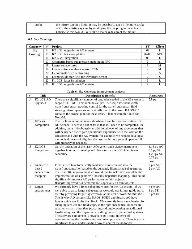
stroke the mirror can hit a limit. It may be possible to get a little more stroke out of the existing system by modifying the coupling to the actuator. Otherwise this would likely take a major redesign of the mount.
6.2 Sky Coverage Category # Project FY Effort
14 K2 LGS: upgrades to AO system 02 L 15 K2 LGS: laser completion 02/03 M/L 16 K2 LGS: integration 03 L 17 Geometric based subaperture mapping in PRC ? S 18 Larger subapertures ? M 19 Lower noise wavefront sensor CCDs ? M 20 Denominator free centroiding ? S 21 Larger guide star field for wavefront sensor ? S 22 K1 LGS: laser installation ? L
Sky Coverage
23 K1 LGS: upgrades to AO system ? L
Table 6. Sky Coverage improvement projects. # Title Description & Benefit Resources 14 K2 LGS AO
upgrades There are a significant number of upgrades needed to the K2 system to support LGS AO. This includes a tip/tilt sensor, a low bandwidth wavefront sensor, tracking control for the wavefront sensor, field steering mirror upgrades and a tip/tilt loop to the laser. KAON 216 contains the project plan for these tasks. Planned completion is for Nov./02.
5.8 py
15 K2 laser completion
The K2 laser is not yet in a state where it can be used for routine LGS AO science. There is a list of tasks that still need to be completed. In addition, there is doubtlessly an additional level of imp rovements that will be needed as we gain operational experience with the laser on the telescope and with the AO system (for example, we need to develop a methodical means of aligning the laser table. A top-level operator UI will probably be needed).
16 K2 LGS integration
On-sky operation of the laser, AO system and science instrument together in order to develop and characterize the LGS AO science capability.
1.15 py AO 0.5 py SA 1.25 py SE 0.75 py laser
17 Geometric based subaperture mapping
PRC is used to automatically load new reconstructors into the wavefront controller based on the currently illuminated subapertures. The first PRC improvement we would like to make is to complete the implementation of a geometric -based subaperture mapping. This could significantly improve AO performance on faint objects. Benefit: Improved AO performance, especially on faint objects.
2 pm SE 2 pw AO
18 Larger subapertures
We currently have a fixed subaperture size for the AO system. If we were able to go to larger subapertures we could use fainter guide stars, thereby providing larger sky coverage at the cost of lower Strehl ratios. This is why AO systems like NAOS, PUEO and Subaru AO have fainter guide star limits than Keck. We currently have a mechanism for changing lenslets and field stops, so the opto-mechanical impacts are relatively small, other than procuring and implementing an additional lenslet array, and the impact on installing these in operational systems. The software component is however significant, in terms of reprogramming the real-time and command processors. There is also a significant task in understanding how to control the no longer
4 pm AO 1 py SE 3 pm OE
19
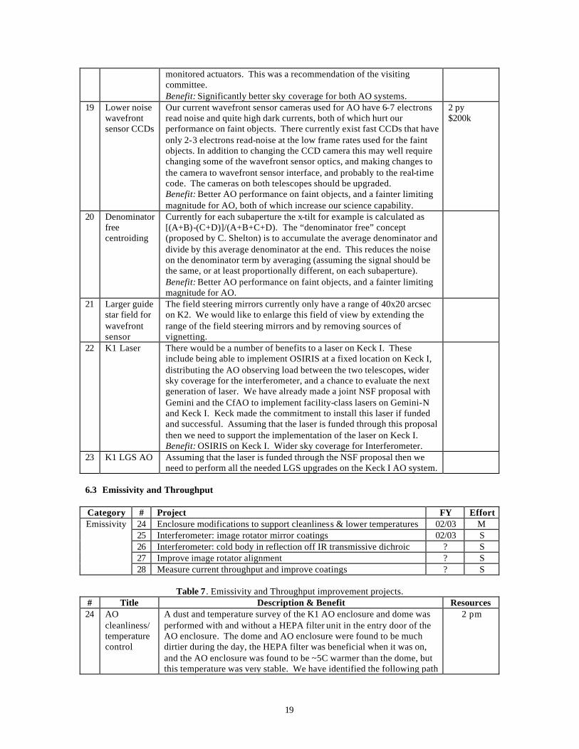
monitored actuators. This was a recommendation of the visiting committee. Benefit: Significantly better sky coverage for both AO systems.
19 Lower noise wavefront sensor CCDs
Our current wavefront sensor cameras used for AO have 6-7 electrons read noise and quite high dark currents, both of which hurt our performance on faint objects. There currently exist fast CCDs that have only 2-3 electrons read-noise at the low frame rates used for the faint objects. In addition to changing the CCD camera this may well require changing some of the wavefront sensor optics, and making changes to the camera to wavefront sensor interface, and probably to the real-time code. The cameras on both telescopes should be upgraded. Benefit: Better AO performance on faint objects, and a fainter limiting magnitude for AO, both of which increase our science capability.
2 py $200k
20 Denominator free centroiding
Currently for each subaperture the x-tilt for example is calculated as [(A+B)-(C+D)]/(A+B+C+D). The “denominator free” concept (proposed by C. Shelton) is to accumulate the average denominator and divide by this average denominator at the end. This reduces the noise on the denominator term by averaging (assuming the signal should be the same, or at least proportionally different, on each subaperture). Benefit: Better AO performance on faint objects, and a fainter limiting magnitude for AO.
21 Larger guide star field for wavefront sensor
The field steering mirrors currently only have a range of 40x20 arcsec on K2. We would like to enlarge this field of view by extending the range of the field steering mirrors and by removing sources of vignetting.
22 K1 Laser There would be a number of benefits to a laser on Keck I. These include being able to implement OSIRIS at a fixed location on Keck I, distributing the AO observing load between the two telescopes, wider sky coverage for the interferometer, and a chance to evaluate the next generation of laser. We have already made a joint NSF proposal with Gemini and the CfAO to implement facility-class lasers on Gemini-N and Keck I. Keck made the commitment to install this laser if funded and successful. Assuming that the laser is funded through this proposal then we need to support the implementation of the laser on Keck I. Benefit: OSIRIS on Keck I. Wider sky coverage for Interferometer.
23 K1 LGS AO Assuming that the laser is funded through the NSF proposal then we need to perform all the needed LGS upgrades on the Keck I AO system.
6.3 Emissivity and Throughput Category # Project FY Effort
24 Enclosure modifications to support cleanliness & lower temperatures 02/03 M 25 Interferometer: image rotator mirror coatings 02/03 S 26 Interferometer: cold body in reflection off IR transmissive dichroic ? S 27 Improve image rotator alignment ? S
Emissivity
28 Measure current throughput and improve coatings ? S
Table 7. Emissivity and Throughput improvement projects. # Title Description & Benefit Resources 24 AO
cleanliness/ temperature control
A dust and temperature survey of the K1 AO enclosure and dome was performed with and without a HEPA filter unit in the entry door of the AO enclosure. The dome and AO enclosure were found to be much dirtier during the day, the HEPA filter was beneficial when it was on, and the AO enclosure was found to be ~5C warmer than the dome, but this temperature was very stable. We have identified the following path
2 pm
20
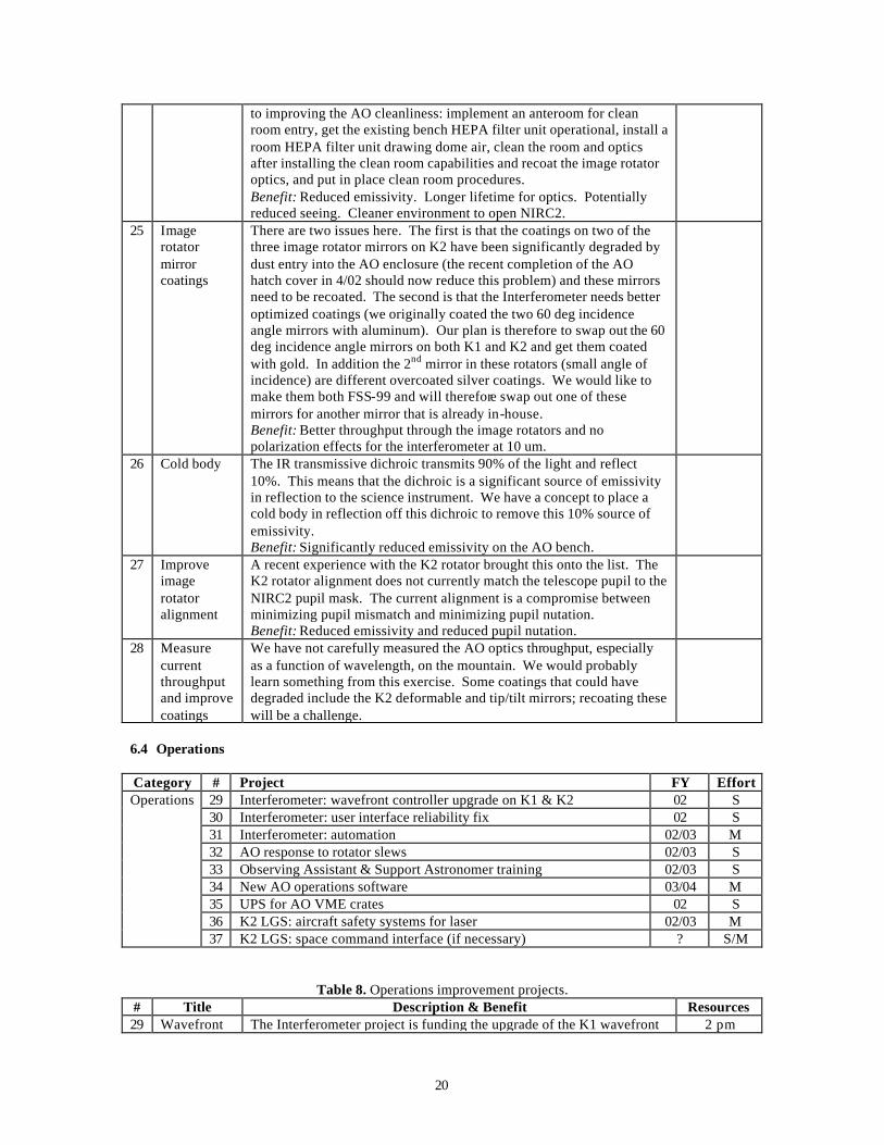
to improving the AO cleanliness: implement an anteroom for clean room entry, get the existing bench HEPA filter unit operational, install a room HEPA filter unit drawing dome air, clean the room and optics after installing the clean room capabilities and recoat the image rotator optics, and put in place clean room procedures. Benefit: Reduced emissivity. Longer lifetime for optics. Potentially reduced seeing. Cleaner environment to open NIRC2.
25 Image rotator mirror coatings
There are two issues here. The first is that the coatings on two of the three image rotator mirrors on K2 have been significantly degraded by dust entry into the AO enclosure (the recent completion of the AO hatch cover in 4/02 should now reduce this problem) and these mirrors need to be recoated. The second is that the Interferometer needs better optimized coatings (we originally coated the two 60 deg incidence angle mirrors with aluminum). Our plan is therefore to swap out the 60 deg incidence angle mirrors on both K1 and K2 and get them coated with gold. In addition the 2nd mirror in these rotators (small angle of incidence) are different overcoated silver coatings. We would like to make them both FSS-99 and will therefore swap out one of these mirrors for another mirror that is already in-house. Benefit: Better throughput through the image rotators and no polarization effects for the interferometer at 10 um.
26 Cold body The IR transmissive dichroic transmits 90% of the light and reflect 10%. This means that the dichroic is a significant source of emissivity in reflection to the science instrument. We have a concept to place a cold body in reflection off this dichroic to remove this 10% source of emissivity. Benefit: Significantly reduced emissivity on the AO bench.
27 Improve image rotator alignment
A recent experience with the K2 rotator brought this onto the list. The K2 rotator alignment does not currently match the telescope pupil to the NIRC2 pupil mask. The current alignment is a compromise between minimizing pupil mismatch and minimizing pupil nutation. Benefit: Reduced emissivity and reduced pupil nutation.
28 Measure current throughput and improve coatings
We have not carefully measured the AO optics throughput, especially as a function of wavelength, on the mountain. We would probably learn something from this exercise. Some coatings that could have degraded include the K2 deformable and tip/tilt mirrors; recoating these will be a challenge.
6.4 Operations Category # Project FY Effort
29 Interferometer: wavefront controller upgrade on K1 & K2 02 S 30 Interferometer: user interface reliability fix 02 S 31 Interferometer: automation 02/03 M 32 AO response to rotator slews 02/03 S 33 Observing Assistant & Support Astronomer training 02/03 S 34 New AO operations software 03/04 M 35 UPS for AO VME crates 02 S 36 K2 LGS: aircraft safety systems for laser 02/03 M
Operations
37 K2 LGS: space command interface (if necessary) ? S/M
Table 8. Operations improvement projects. # Title Description & Benefit Resources 29 Wavefront The Interferometer project is funding the upgrade of the K1 wavefront 2 pm
21
controller upgrade
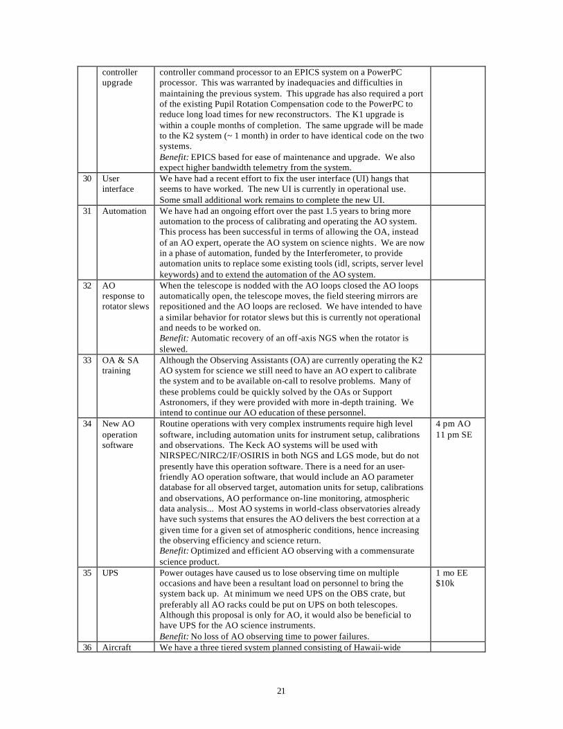
controller command processor to an EPICS system on a PowerPC processor. This was warranted by inadequacies and difficulties in maintaining the previous system. This upgrade has also required a port of the existing Pupil Rotation Compensation code to the PowerPC to reduce long load times for new reconstructors. The K1 upgrade is within a couple months of completion. The same upgrade will be made to the K2 system (~ 1 month) in order to have identical code on the two systems. Benefit: EPICS based for ease of maintenance and upgrade. We also expect higher bandwidth telemetry from the system.
30 User interface
We have had a recent effort to fix the user interface (UI) hangs that seems to have worked. The new UI is currently in operational use. Some small additional work remains to complete the new UI.
31 Automation We have had an ongoing effort over the past 1.5 years to bring more automation to the process of calibrating and operating the AO system. This process has been successful in terms of allowing the OA, instead of an AO expert, operate the AO system on science nights. We are now in a phase of automation, funded by the Interferometer, to provide automation units to replace some existing tools (idl, scripts, server level keywords) and to extend the automation of the AO system.
32 AO response to rotator slews
When the telescope is nodded with the AO loops closed the AO loops automatically open, the telescope moves, the field steering mirrors are repositioned and the AO loops are reclosed. We have intended to have a similar behavior for rotator slews but this is currently not operational and needs to be worked on. Benefit: Automatic recovery of an off-axis NGS when the rotator is slewed.
33 OA & SA training
Although the Observing Assistants (OA) are currently operating the K2 AO system for science we still need to have an AO expert to calibrate the system and to be available on-call to resolve problems. Many of these problems could be quickly solved by the OAs or Support Astronomers, if they were provided with more in-depth training. We intend to continue our AO education of these personnel.
34 New AO operation software
Routine operations with very complex instruments require high level software, including automation units for instrument setup, calibrations and observations. The Keck AO systems will be used with NIRSPEC/NIRC2/IF/OSIRIS in both NGS and LGS mode, but do not presently have this operation software. There is a need for an user-friendly AO operation software, that would include an AO parameter database for all observed target, automation units for setup, calibrations and observations, AO performance on-line monitoring, atmospheric data analysis... Most AO systems in world-class observatories already have such systems that ensures the AO delivers the best correction at a given time for a given set of atmospheric conditions, hence increasing the observing efficiency and science return. Benefit: Optimized and efficient AO observing with a commensurate science product.
4 pm AO 11 pm SE
35 UPS Power outages have caused us to lose observing time on multiple occasions and have been a resultant load on personnel to bring the system back up. At minimum we need UPS on the OBS crate, but preferably all AO racks could be put on UPS on both telescopes. Although this proposal is only for AO, it would also be beneficial to have UPS for the AO science instruments. Benefit: No loss of AO observing time to power failures.
1 mo EE $10k
36 Aircraft We have a three tiered system planned consisting of Hawaii-wide
22
safety systems
mosaic radar, wide field visible cameras and an IR boresite camera. Only the boresite camera is currently in place. Once developed the entire system needs FAA approval. We are currently using human spotters.
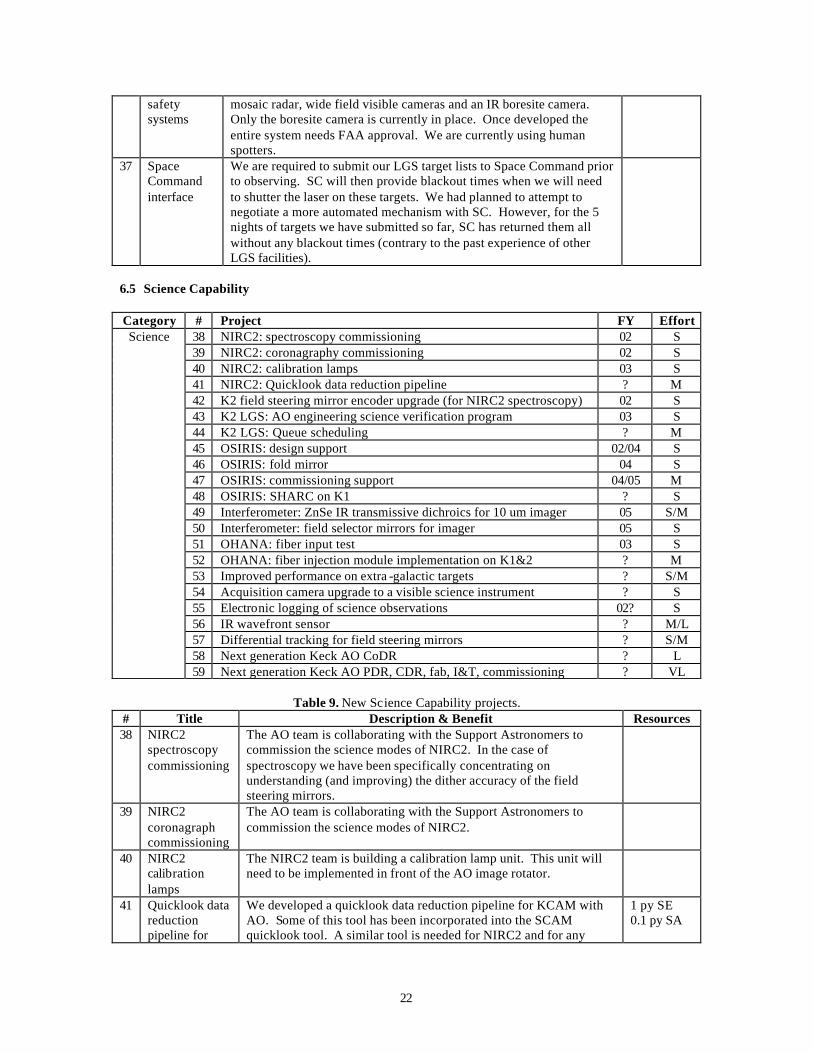
37 Space Command interface
We are required to submit our LGS target lists to Space Command prior to observing. SC will then provide blackout times when we will need to shutter the laser on these targets. We had planned to attempt to negotiate a more automated mechanism with SC. However, for the 5 nights of targets we have submitted so far, SC has returned them all without any blackout times (contrary to the past experience of other LGS facilities).
6.5 Science Capability Category # Project FY Effort
38 NIRC2: spectroscopy commissioning 02 S 39 NIRC2: coronagraphy commissioning 02 S 40 NIRC2: calibration lamps 03 S 41 NIRC2: Quicklook data reduction pipeline ? M 42 K2 field steering mirror encoder upgrade (for NIRC2 spectroscopy) 02 S 43 K2 LGS: AO engineering science verification program 03 S 44 K2 LGS: Queue scheduling ? M 45 OSIRIS: design support 02/04 S 46 OSIRIS: fold mirror 04 S 47 OSIRIS: commissioning support 04/05 M 48 OSIRIS: SHARC on K1 ? S 49 Interferometer: ZnSe IR transmissive dichroics for 10 um imager 05 S/M 50 Interferometer: field selector mirrors for imager 05 S 51 OHANA: fiber input test 03 S 52 OHANA: fiber injection module implementation on K1&2 ? M 53 Improved performance on extra -galactic targets ? S/M 54 Acquisition camera upgrade to a visible science instrument ? S 55 Electronic logging of science observations 02? S 56 IR wavefront sensor ? M/L 57 Differential tracking for field steering mirrors ? S/M 58 Next generation Keck AO CoDR ? L
Science
59 Next generation Keck AO PDR, CDR, fab, I&T, commissioning ? VL
Table 9. New Science Capability projects. # Title Description & Benefit Resources 38 NIRC2
spectroscopy commissioning
The AO team is collaborating with the Support Astronomers to commission the science modes of NIRC2. In the case of spectroscopy we have been specifically concentrating on understanding (and improving) the dither accuracy of the field steering mirrors.
39 NIRC2 coronagraph commissioning
The AO team is collaborating with the Support Astronomers to commission the science modes of NIRC2.
40 NIRC2 calibration lamps
The NIRC2 team is building a calibration lamp unit. This unit will need to be implemented in front of the AO image rotator.
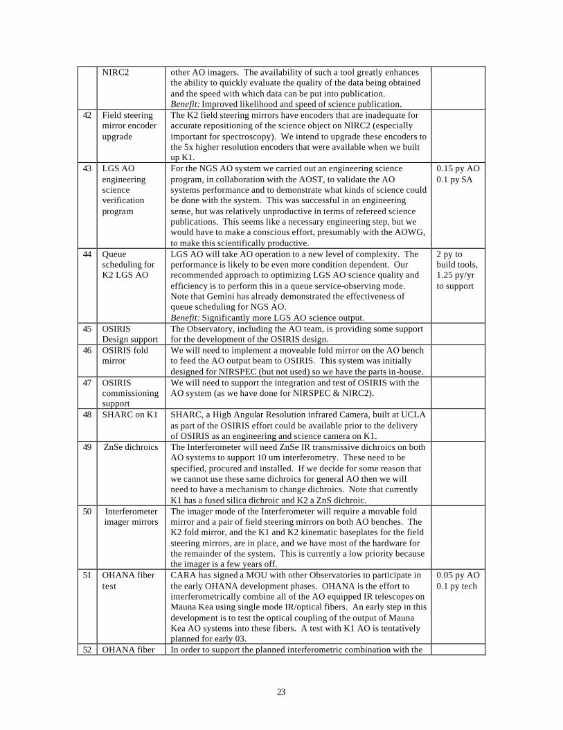
41 Quicklook data reduction pipeline for
We developed a quicklook data reduction pipeline for KCAM with AO. Some of this tool has been incorporated into the SCAM quicklook tool. A similar tool is needed for NIRC2 and for any
1 py SE 0.1 py SA
23
NIRC2 other AO imagers. The availability of such a tool greatly enhances the ability to quickly evaluate the quality of the data being obtained and the speed with which data can be put into publication. Benefit: Improved likelihood and speed of science publication.
42 Field steering mirror encoder upgrade
The K2 field steering mirrors have encoders that are inadequate for accurate repositioning of the science object on NIRC2 (especially important for spectroscopy). We intend to upgrade these encoders to the 5x higher resolution encoders that were available when we built up K1.
43 LGS AO engineering science verification program
For the NGS AO system we carried out an engineering science program, in collaboration with the AOST, to validate the AO systems performance and to demonstrate what kinds of science could be done with the system. This was successful in an engineering sense, but was relatively unproductive in terms of refereed science publications. This seems like a necessary engineering step, but we would have to make a conscious effort, presumably with the AOWG, to make this scientifically productive.
0.15 py AO 0.1 py SA
44 Queue scheduling for K2 LGS AO
LGS AO will take AO operation to a new level of complexity. The performance is likely to be even more condition dependent. Our recommended approach to optimizing LGS AO science quality and efficiency is to perform this in a queue service-observing mode. Note that Gemini has already demonstrated the effectiveness of queue scheduling for NGS AO. Benefit: Significantly more LGS AO science output.
2 py to build tools, 1.25 py/yr to support
45 OSIRIS Design support
The Observatory, including the AO team, is providing some support for the development of the OSIRIS design.
46 OSIRIS fold mirror
We will need to implement a moveable fold mirror on the AO bench to feed the AO output beam to OSIRIS. This system was initially designed for NIRSPEC (but not used) so we have the parts in-house.
47 OSIRIS commissioning support
We will need to support the integration and test of OSIRIS with the AO system (as we have done for NIRSPEC & NIRC2).
48 SHARC on K1 SHARC, a High Angular Resolution infrared Camera, built at UCLA as part of the OSIRIS effort could be available prior to the delivery of OSIRIS as an engineering and science camera on K1.
49 ZnSe dichroics The Interferometer will need ZnSe IR transmissive dichroics on both AO systems to support 10 um interferometry. These need to be specified, procured and installed. If we decide for some reason that we cannot use these same dichroics for general AO then we will need to have a mechanism to change dichroics. Note that currently K1 has a fused silica dichroic and K2 a ZnS dichroic.
50 Interferometer imager mirrors
The imager mode of the Interferometer will require a movable fold mirror and a pair of field steering mirrors on both AO benches. The K2 fold mirror, and the K1 and K2 kinematic baseplates for the field steering mirrors, are in place, and we have most of the hardware for the remainder of the system. This is currently a low priority because the imager is a few years off.
51 OHANA fiber test
CARA has signed a MOU with other Observatories to participate in the early OHANA development phases. OHANA is the effort to interferometrically combine all of the AO equipped IR telescopes on Mauna Kea using single mode IR/optical fibers. An early step in this development is to test the optical coupling of the output of Mauna Kea AO systems into these fibers. A test with K1 AO is tentatively planned for early 03.
0.05 py AO 0.1 py tech
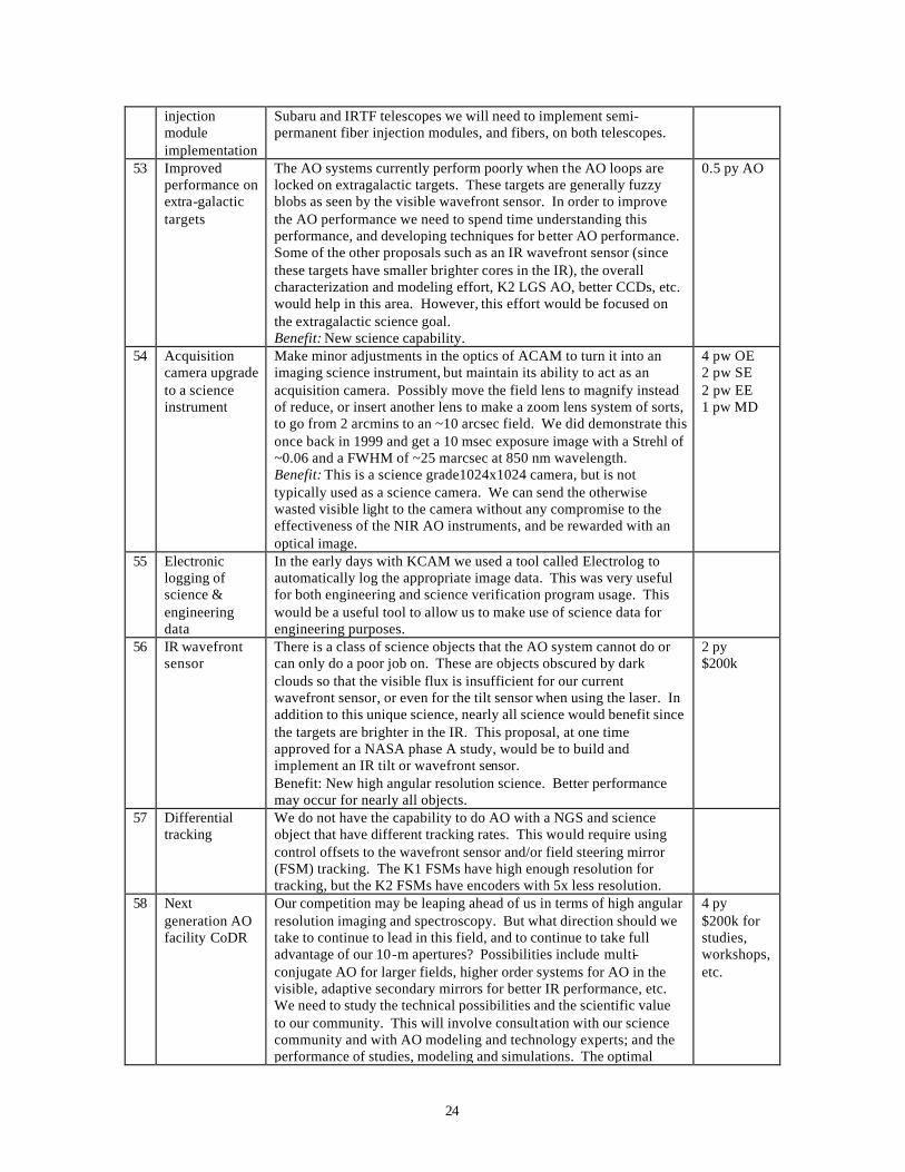
52 OHANA fiber In order to support the planned interferometric combination with the
24
injection module implementation
Subaru and IRTF telescopes we will need to implement semi-permanent fiber injection modules, and fibers, on both telescopes.
53 Improved performance on extra-galactic targets
The AO systems currently perform poorly when the AO loops are locked on extragalactic targets. These targets are generally fuzzy blobs as seen by the visible wavefront sensor. In order to improve the AO performance we need to spend time understanding this performance, and developing techniques for better AO performance. Some of the other proposals such as an IR wavefront sensor (since these targets have smaller brighter cores in the IR), the overall characterization and modeling effort, K2 LGS AO, better CCDs, etc. would help in this area. However, this effort would be focused on the extragalactic science goal. Benefit: New science capability.
0.5 py AO
54 Acquisition camera upgrade to a science instrument
Make minor adjustments in the optics of ACAM to turn it into an imaging science instrument, but maintain its ability to act as an acquisition camera. Possibly move the field lens to magnify instead of reduce, or insert another lens to make a zoom lens system of sorts, to go from 2 arcmins to an ~10 arcsec field. We did demonstrate this once back in 1999 and get a 10 msec exposure image with a Strehl of ~0.06 and a FWHM of ~25 marcsec at 850 nm wavelength. Benefit: This is a science grade1024x1024 camera, but is not typically used as a science camera. We can send the otherwise wasted visible light to the camera without any compromise to the effectiveness of the NIR AO instruments, and be rewarded with an optical image.
4 pw OE 2 pw SE 2 pw EE 1 pw MD
55 Electronic logging of science & engineering data
In the early days with KCAM we used a tool called Electrolog to automatically log the appropriate image data. This was very useful for both engineering and science verification program usage. This would be a useful tool to allow us to make use of science data for engineering purposes.
56 IR wavefront sensor
There is a class of science objects that the AO system cannot do or can only do a poor job on. These are objects obscured by dark clouds so that the visible flux is insufficient for our current wavefront sensor, or even for the tilt sensor when using the laser. In addition to this unique science, nearly all science would benefit since the targets are brighter in the IR. This proposal, at one time approved for a NASA phase A study, would be to build and implement an IR tilt or wavefront sensor. Benefit: New high angular resolution science. Better performance may occur for nearly all objects.
2 py $200k
57 Differential tracking
We do not have the capability to do AO with a NGS and science object that have different tracking rates. This would require using control offsets to the wavefront sensor and/or field steering mirror (FSM) tracking. The K1 FSMs have high enough resolution for tracking, but the K2 FSMs have encoders with 5x less resolution.
58 Next generation AO facility CoDR
Our competition may be leaping ahead of us in terms of high angular resolution imaging and spectroscopy. But what direction should we take to continue to lead in this field, and to continue to take full advantage of our 10-m apertures? Possibilities include multi-conjugate AO for larger fields, higher order systems for AO in the visible, adaptive secondary mirrors for better IR performance, etc. We need to study the technical possibilities and the scientific value to our community. This will involve consultation with our science community and with AO modeling and technology experts; and the performance of studies, modeling and simulations. The optimal
4 py $200k for studies, workshops, etc.
25
science instruments to go with next generation AO should also be addressed. The results should be published in a blue book, which we should then use to seek approval from the CARA community and funding from the appropriate organization(s). Benefit: Unprecedented high angular resolution science.
59 Next generation AO facility
This task included the remaining design review process, fabrication, assembly, lab and telescope integration and test, pre-ship and acceptance reviews, engineering science verification, etc.
6.6 Performance Characterization & Modeling Category # Project FY Effort
60 Atmospheric characterization tool 02 S 61 CfAO postdoc performance modeling & characterization effort 03/04 S/M
Character- ization
62 Additional AO characterization & modeling efforts ? M/L
Table 10. Performance Characterization and Modeling projects. # Title Description & Benefit Resources 60 Atmospheric
characterization tool
We have been collaborating with M. Schoeck at UCI to build a tool to calculate r0 and tau0 both using telemetry and diagnostics data. We are currently working on calibrating this tool (and are learning about our system in the process). Benefit: An on-line tool to inform of us the current seeing conditions. This will provide a guide to how the AO system should be performing.
61 Performance modeling & character-ization I
A proposal was submitted to the CfAO by Bruce Macintosh for a Postdoc to work collaboratively between Keck and the CfAO. The postdoc has been identified and will start work this fall. Our current plan is for this postdoc to develop a model of the Keck AO system and to start characterizing the Keck AO performance via this model.
62 Performance modeling & character-ization II
We only have an anecdotal understanding of the current performance of our AO systems. Understanding the performance will require a process of careful characterization and modeling of the system (note that the knowledge gained in this process would be useful in developing our next generation AO system). This understanding is needed to understand where and how to improve performance. These performance improvements should then be undertaken at a level of effort (unless additional proposals are made). Benefit: Better characterization would benefit the astronomers using the system. Improved understanding of the AO system would result in performance improvements.
1 py AO
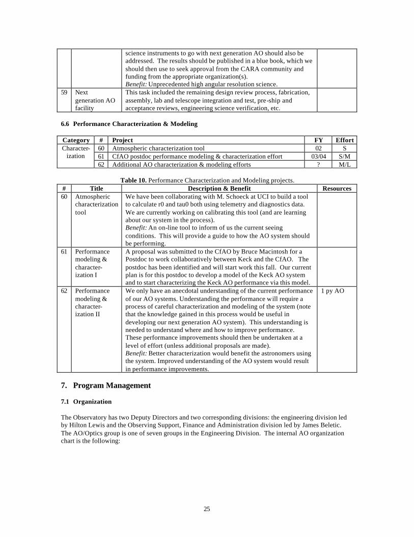
7. Program Management 7.1 Organization The Observatory has two Deputy Directors and two corresponding divisions: the engineering division led by Hilton Lewis and the Observing Support, Finance and Administration division led by James Beletic. The AO/Optics group is one of seven groups in the Engineering Division. The internal AO organization chart is the following:
26
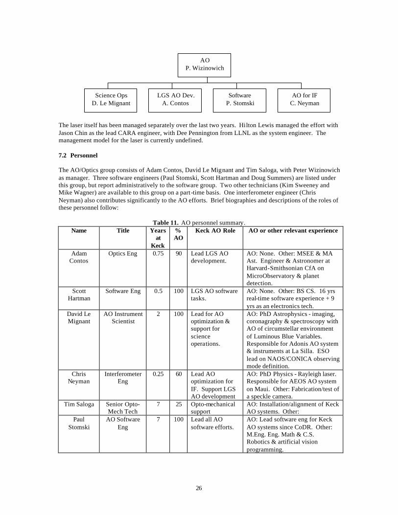
The laser itself has been managed separately over the last two years. Hilton Lewis managed the effort with Jason Chin as the lead CARA engineer, with Dee Pennington from LLNL as the system engineer. The management model for the laser is currently undefined. 7.2 Personnel The AO/Optics group consists of Adam Contos, David Le Mignant and Tim Saloga, with Peter Wizinowich as manager. Three software engineers (Paul Stomski, Scott Hartman and Doug Summers) are listed under this group, but report administratively to the software group. Two other technicians (Kim Sweeney and Mike Wagner) are available to this group on a part-time basis. One interferometer engineer (Chris Neyman) also contributes significantly to the AO efforts. Brief biographies and descriptions of the roles of these personnel follow:
Table 11. AO personnel summary. Name Title Years
at Keck
% AO
Keck AO Role AO or other relevant experience
Adam Contos
Optics Eng 0.75 90 Lead LGS AO development.
AO: None. Other: MSEE & MA Ast. Engineer & Astronomer at Harvard-Smithsonian CfA on MicroObservatory & planet detection.
Scott Hartman
Software Eng 0.5 100 LGS AO software tasks.
AO: None. Other: BS CS. 16 yrs real-time software experience + 9 yrs as an electronics tech.
David Le Mignant
AO Instrument Scientist
2 100 Lead for AO optimization & support for science operations.
AO: PhD Astrophysics - imaging, coronagraphy & spectroscopy with AO of circumstellar environment of Luminous Blue Variables. Responsible for Adonis AO system & instruments at La Silla. ESO lead on NAOS/CONICA observing mode definition.
Chris Neyman
Interferometer Eng
0.25 60 Lead AO optimization for IF. Support LGS AO development
AO: PhD Physics - Rayleigh laser. Responsible for AEOS AO system on Maui. Other: Fabrication/test of a speckle camera.
Tim Saloga Senior Opto-Mech Tech
7 25 Opto-mechanical support
AO: Installation/alignment of Keck AO systems. Other:
Paul Stomski
AO Software Eng
7 100 Lead all AO software efforts.
AO: Lead software eng for Keck AO systems since CoDR. Other: M.Eng. Eng. Math & C.S. Robotics & artificial vision programming.
AO P. Wizinowich
Science Ops D. Le Mignant
LGS AO Dev. A. Contos
Software P. Stomski
AO for IF C. Neyman
27
Doug Summers
Software Eng 0.75 100 LGS AO software tasks. Laser software.
AO: Built/implemented the Keck Laser Traffic Control system software. Other: BS CS. 15-yrs experience in real-time applications.
Kim Sweeney
Mechanical Draftsman
5 40 Opto-mechanical drawings.
AO: Produced all of the AO opto-mechanical drawings in 3-D ACAD. Similar previous role at CFHT.
Mike Wagner
Electronics Tech
33 Electronics support.
Peter Wizinowich
AO/Optics/IF Manager
10 33 Mgmt & system eng.
AO: Mgmt/system eng for Keck AO since inception. Started Steward Obs AO group. Other: PhD in Optical Eng. Optics/instrument mgr/eng/tech at Keck, Steward Obs., CFHT & UofT Southern Obs.
New hire Laser Optics Engineer
0 100 Laser completion, integration with LGS AO, & operation
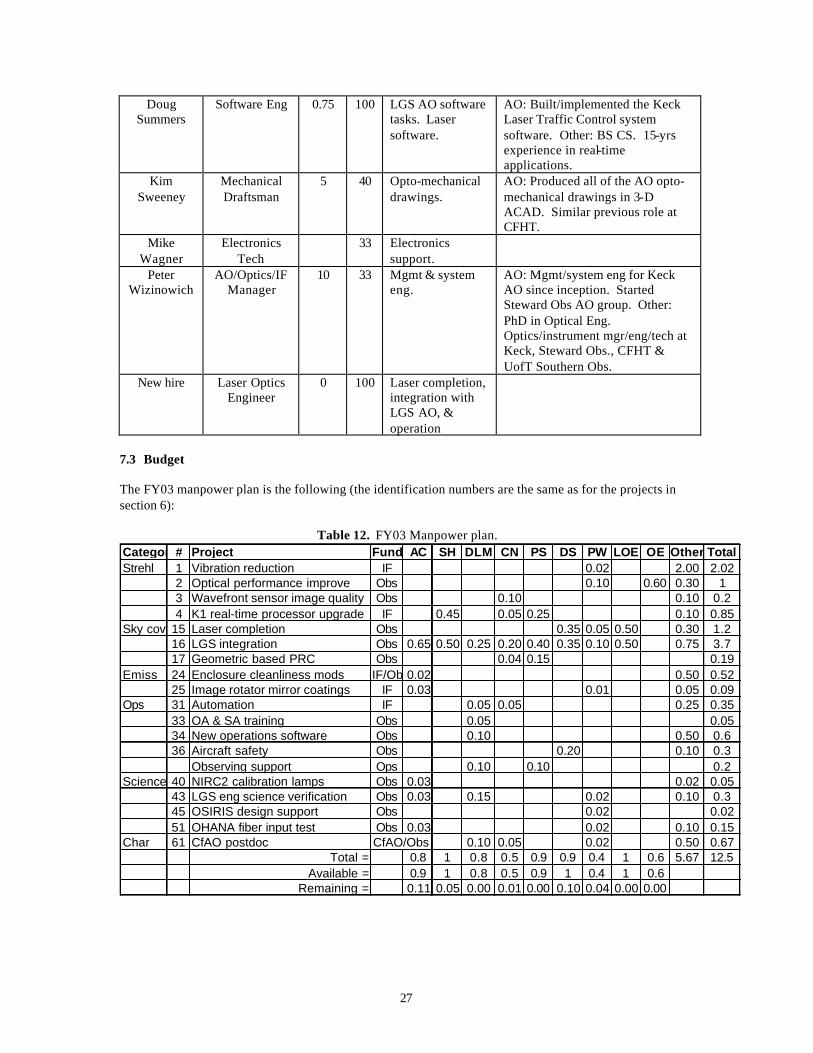
7.3 Budget The FY03 manpower plan is the following (the identification numbers are the same as for the projects in section 6):
Table 12. FY03 Manpower plan. Category# Project Fund AC SH DLM CN PS DS PW LOE OE Other TotalStrehl 1 Vibration reduction IF 0.02 2.00 2.02
2 Optical performance improve Obs 0.10 0.60 0.30 13 Wavefront sensor image quality Obs 0.10 0.10 0.24 K1 real-time processor upgrade IF 0.45 0.05 0.25 0.10 0.85
Sky cov 15 Laser completion Obs 0.35 0.05 0.50 0.30 1.216 LGS integration Obs 0.65 0.50 0.25 0.20 0.40 0.35 0.10 0.50 0.75 3.717 Geometric based PRC Obs 0.04 0.15 0.19
Emiss 24 Enclosure cleanliness mods IF/Ob 0.02 0.50 0.5225 Image rotator mirror coatings IF 0.03 0.01 0.05 0.09
Ops 31 Automation IF 0.05 0.05 0.25 0.3533 OA & SA training Obs 0.05 0.0534 New operations software Obs 0.10 0.50 0.636 Aircraft safety Obs 0.20 0.10 0.3
Observing support Ops 0.10 0.10 0.2Science 40 NIRC2 calibration lamps Obs 0.03 0.02 0.05
43 LGS eng science verification Obs 0.03 0.15 0.02 0.10 0.345 OSIRIS design support Obs 0.02 0.0251 OHANA fiber input test Obs 0.03 0.02 0.10 0.15
Char 61 CfAO postdoc CfAO/Obs 0.10 0.05 0.02 0.50 0.67Total = 0.8 1 0.8 0.5 0.9 0.9 0.4 1 0.6 5.67 12.5
Available = 0.9 1 0.8 0.5 0.9 1 0.4 1 0.6Remaining = 0.11 0.05 0.00 0.01 0.00 0.10 0.04 0.00 0.00
28
7.4 Schedule We have a detailed schedule for the LGS AO tools (KAON 216); weekly LGS AO group meetings are held including weekly status reports with respect to the schedule. There is a detailed list of prioritized software tasks and a weekly AO software meeting. None of the other projects have a schedule, other than approximate need dates.
29
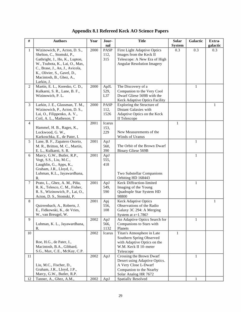
Appendix 8.1 Refereed Keck AO Science Papers
# Authors Year Jour-nal
Title Solar System
Galactic Extra-galactic
1 Wizinowich, P., Acton, D. S., Shelton, C., Stomski, P., Gathright, J., Ho, K., Lupton, W., Tsubota, K., Lai, O., Max, C., Brase, J., An, J., Avicola, K., Olivier, S., Gavel, D., Macintosh, B., Ghez, A., Larkin, J.
2000 PASP 112, 315
First Light Adaptive Optics Images from the Keck II Telescope: A New Era of High Angular Resolution Imagery
0.3 0.3 0.3
2 Martín, E. L., Koresko, C. D., Kulkarni, S. R., Lane, B. F., Wizinowich, P. L.
2000 ApJL 529, L37
The Discovery of a Companion to the Very Cool Dwarf Gliese 569B with the Keck Adaptive Optics Facility
1
3 Larkin, J. E., Glassman, T. M., Wizinowich, P., Acton, D. S., Lai, O., Filippenko, A. V., Coil, A. L., Matheson, T
2000 PASP 112, 1526
Exploring the Structure of Distant Galaxies with Adaptive Optics on the Keck II Telescope
1
4 Hammel, H. B., Rages, K., Lockwood, G. W., Karkoschka, E., de Pater, I.
2001 Icarus 153, 229
New Measurements of the Winds of Uranus
1
5 Lane, B. F., Zapatero Osorio, M. R., Britton, M. C., Martín, E. L., Kulkarni, S. R.
2001 ApJ 560, 390
The Orbit of the Brown Dwarf Binary Gliese 569B
1
6 Marcy, G.W., Butler, R.P., Vogt, S.S., Liu, M.C., Laughlin, G., Apps, K., Graham, J.R., Lloyd, J., Luhman, K.L., Jayawardhana, R.
2001 ApJ 555, 418
Two Substellar Companions Orbiting HD 168443
1
7 Prato, L., Ghez, A. M., Piña, R. K., Telesco, C. M., Fisher, R. S., Wizinowich, P., Lai, O., Acton, D. S., Stomski, P.
2001 ApJ 549, 590
Keck Diffraction-limited Imaging of the Young Quadruple Star System HD 98800
1
8 Quirrenbach, A., Roberts, J. E., Fidkowski, K., de Vries, W., van Breugel, W.
2001 Apj 556, 108
Keck Adaptive Optics Observations of the Radio Galaxy 3C 294: A Merging System at z=1.786?
1
9 Luhman, K. L., Jayawardhana, R.
2002 ApJ 566, 1132
An Adaptive Optics Search for Companions to Stars with Planets
1
10
Roe, H.G., de Pater, I., Macintosh, B.A., Gibbard, S.G., Max, C.E., McKay, C.P.
2002 Icarus Titan's Atmosphere in Late Southern Spring Observed with Adaptive Optics on the W.M. Keck II 10-meter Telescope
1
11
Liu, M.C., Fischer, D., Graham, J.R., Lloyd, J.P., Marcy, G.W., Butler, R.P.
2002 ApJ Crossing the Brown Dwarf Desert using Adaptive Optics. A Very Close L-Dwarf Companion to the Nearby Solar Analog HR 7672
1
12 Tanner, A., Ghez, A.M., 2002 ApJ Spatially Resolved 1
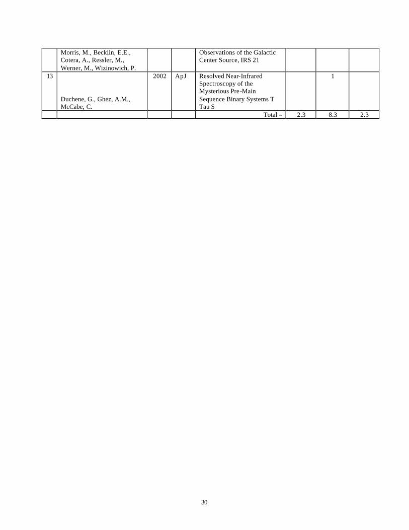
30
Morris, M., Becklin, E.E., Cotera, A., Ressler, M., Werner, M., Wizinowich, P.
Observations of the Galactic Center Source, IRS 21
13
Duchene, G., Ghez, A.M., McCabe, C.
2002 ApJ Resolved Near-Infrared Spectroscopy of the Mysterious Pre-Main Sequence Binary Systems T Tau S
1
Total = 2.3 8.3 2.3
31
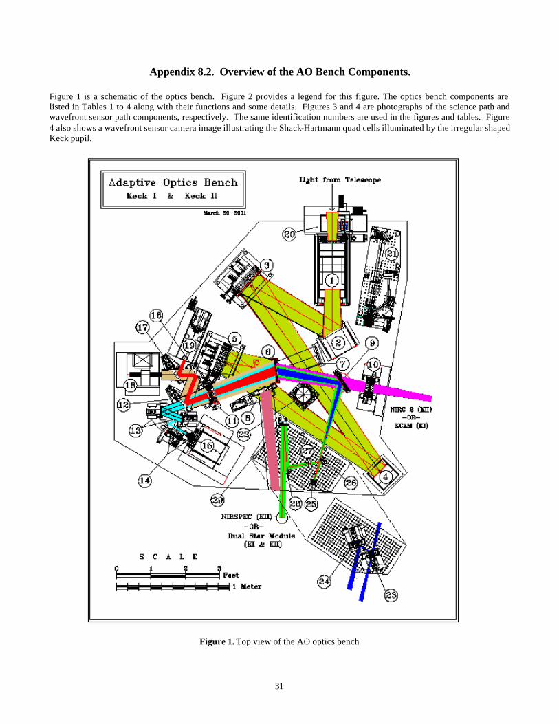
Appendix 8.2. Overview of the AO Bench Components.
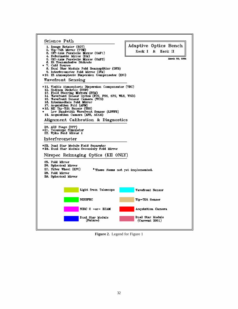
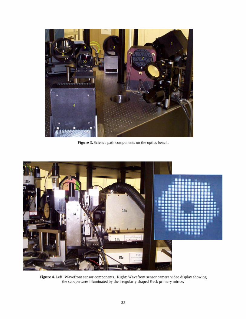
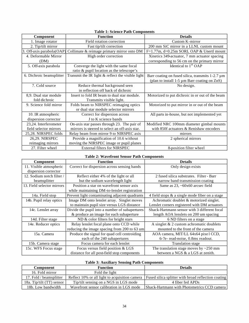
Figure 1 is a schematic of the optics bench. Figure 2 provides a legend for this figure. The optics bench components are listed in Tables 1 to 4 along with their functions and some details. Figures 3 and 4 are photographs of the science path and wavefront sensor path components, respectively. The same identification numbers are used in the figures and tables. Figure 4 also shows a wavefront sensor camera image illustrating the Shack-Hartmann quad cells illuminated by the irregular shaped Keck pupil.
Figure 1. Top view of the AO optics bench
32
Figure 2. Legend for Figure 1
33
4
Figure 3. Science path components on the optics bench.
Figure 4. Left: Wavefront sensor components. Right: Wavefront sensor camera video display showing the subapertures illuminated by the irregularly shaped Keck primary mirror.
4
2
1
5
3
22
6
15a
15b
15c
14 13
12 18b
34
Table 1: Science Path Components Component Function Details
1. Image rotator Field rotation correction Custom K-mirror 2. Tip/tilt mirror Fast tip/tilt correction 200 mm SiC mirror in a LLNL custom mount
3. Off-axis parabola(OAP) Collimate & reimage primary mirror onto DM F=1.77m, d=0.25m SORL OAP & Unertl mount 4. Deformable Mirror
(DM) High order correction Xinetics 349-actuator, 7 mm actuator spacing
corresponding to 56 cm on the primary mirror 5. Off-axis parabola Converge the light with the same focal
ratio & pupil location as the telescope’s Identical to 1st OAP
6. Dichroic beamsplitter Transmit the IR light & reflect the visible light Barr coating on fused silica, transmits 1-2.7 µm (plan to install 1-5 µm Barr coating on ZnS)
7. Cold source Reduce thermal background seen in reflection off back of dichroic
No design.
8,9. Dual star module fold dichroic
Insert to fold IR beam to dual star module. Transmits visible light.
Motorized to put dichroic in or out of the beam
9. Science fold mirror Folds beam to NIRSPEC reimaging optics or dual star module selector mirrors
Motorized to put mirror in or out of the beam
10. IR atmospheric dispersion corrector
Correct for dispersion across J to K science bands
All parts in-house, but not implemented yet
23,24. Interferometer field selector mirrors
On-axis star passes through 23. The pair of mirrors is steered to select an off-axis star.
Modified NRC 100mm diameter gimbal mounts with 850f actuators & Renishaw encoders
25,28. NIRSPEC folds Relay beam from mirror 9 to NIRSPEC axis mirrors 26,29. NIRSPEC reimaging mirrors
Provide a magnification of 10.6 without moving the NIRSPEC image or pupil planes
2 spherical mirrors
27. Filter wheel External filters for NIRSPEC 8-position filter wheel
Table 2: Wavefront Sensor Path Components Component Function Details
11. Visible atmospheric dispersion corrector
Correct for dispersion across sensing bands Only design exists
12. Sodium notch filter / beamsplitter
Reflect either 4% of the light or all but the sodium wavelength light
2 fused silica substrates. Filter - Barr narrow band transmission coating
13. Field selector mirrors Position a star on wavefront sensor axis while maintaining DM-to-lenslet registration
Same as 23, ~60x60 arcsec field
14a. Field stop Prevent light contaminating adjacent quadrants 4 field stops & a single mode fiber on a stage 14b. Pupil relay optics Image DM onto lenslet array. Singlet moves
to maintain pupil size versus LGS distance Achromatic doublet & motorized singlet.
Lenslet corners registered with DM actuators 14c. Lenslet array Divide the pupil into a number of subapertures
& produce an image for each subaperture Shack-Hartmann sensor with 3 different focal
length AOA lenslets on 200 um spacing 14d. Filter stage ND & color filters for bright stars 6 ND filters on a stage
14e. Reducer optics Relay lenslet focal plane onto CCD while reducing the image spacing from 200 to 63 um
A singlet & 2 custom achromatic doublets mounted to the front of the camera
15a. Camera Produce the signal for quad cell centroiding each of the 240 subapertures
AOA camera, MIT/LL 64x64 pixe l CCD, 6-7e- read-noise, 0.8ms readout.
15b. Camera stage Focus camera for each lenslet Translation stage 15c. WFS Focus stage
Focus versus field position & LGS
distance for all post-field stop components The translation stage moves by ~250 mm
between a NGS & a LGS at zenith.
Table 3: Auxiliary Sensing Path Components Component Function Details
16. Fold mirror Fold the light 17. Fold / beamsplitter Reflect 10% or all light to acquisition camera Fused silica splitter with broad reflection coating
18a. Tip/tilt (TT) sensor Tip/tilt sensing on a NGS in LGS mode 4 fiber fed APDs 18b. Low bandwidth Wavefront sensor calibration in LGS mode Shack-Hartmann with Photometrics CCD camera
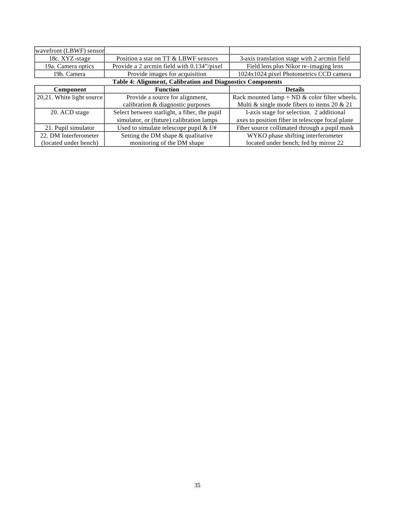
35
wavefront (LBWF) sensor 18c. XYZ -stage Position a star on TT & LBWF sensors 3-axis translation stage with 2 arcmin field
19a. Camera optics Provide a 2 arcmin field with 0.134”/pixel Field lens plus Nikor re-imaging lens 19b. Camera Provide images for acquisition 1024x1024 pixel Photometrics CCD camera
Table 4: Alignment, Calibration and Diagnostics Components Component Function Details
20,21. White light source Provide a source for alignment, calibration & diagnostic purposes
Rack mounted lamp + ND & color filter wheels. Multi & single mode fibers to items 20 & 21
20. ACD stage Select between starlight, a fiber, the pupil simulator, or (future) calibration lamps
1-axis stage for selection. 2 additional axes to position fiber in telescope focal plane
21. Pupil simulator Used to simulate telescope pupil & f/# Fiber source collimated through a pupil mask 22. DM Interferometer (located under bench)
Setting the DM shape & qualitative monitoring of the DM shape
WYKO phase shifting interferometer located under bench; fed by mirror 22
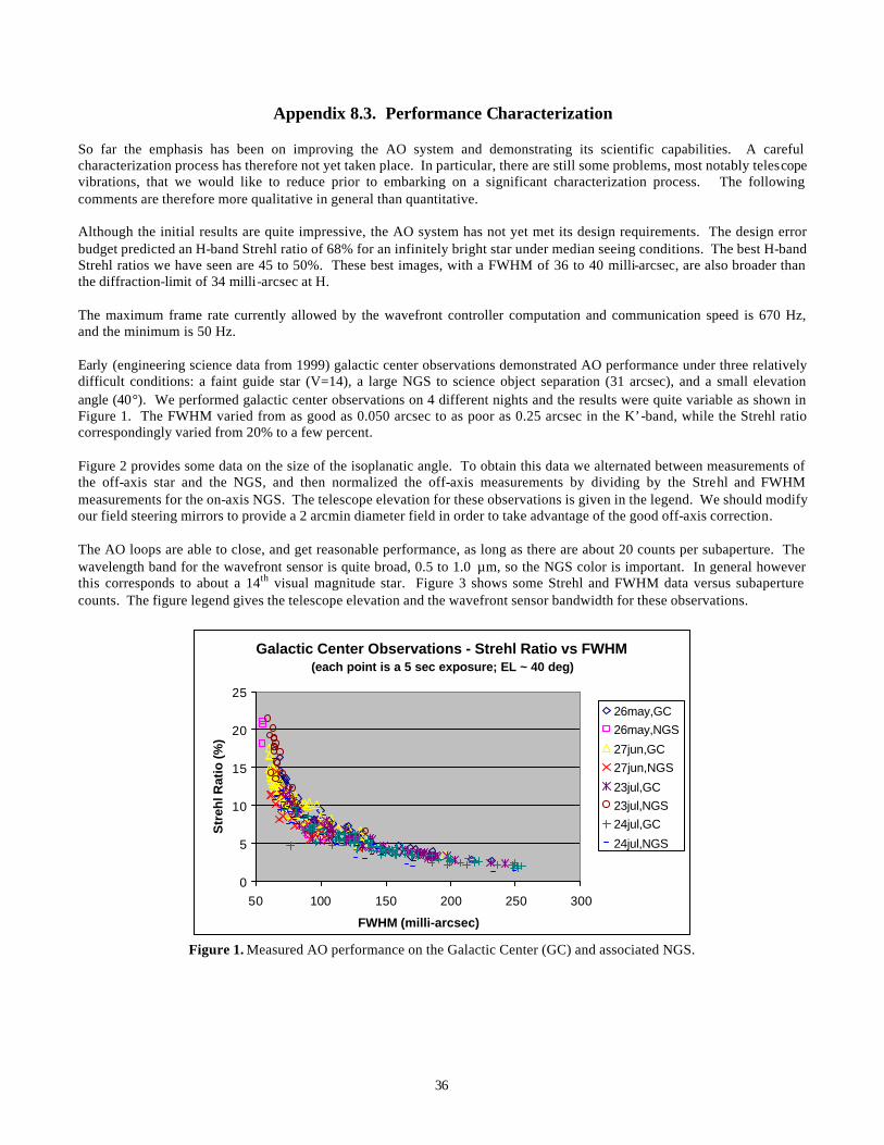
36
Appendix 8.3. Performance Characterization
So far the emphasis has been on improving the AO system and demonstrating its scientific capabilities. A careful characterization process has therefore not yet taken place. In particular, there are still some problems, most notably telescope vibrations, that we would like to reduce prior to embarking on a significant characterization process. The following comments are therefore more qualitative in general than quantitative. Although the initial results are quite impressive, the AO system has not yet met its design requirements. The design error budget predicted an H-band Strehl ratio of 68% for an infinitely bright star under median seeing conditions. The best H-band Strehl ratios we have seen are 45 to 50%. These best images, with a FWHM of 36 to 40 milli-arcsec, are also broader than the diffraction-limit of 34 milli-arcsec at H. The maximum frame rate currently allowed by the wavefront controller computation and communication speed is 670 Hz, and the minimum is 50 Hz. Early (engineering science data from 1999) galactic center observations demonstrated AO performance under three relatively difficult conditions: a faint guide star (V=14), a large NGS to science object separation (31 arcsec), and a small elevation angle (40°). We performed galactic center observations on 4 different nights and the results were quite variable as shown in Figure 1. The FWHM varied from as good as 0.050 arcsec to as poor as 0.25 arcsec in the K’-band, while the Strehl ratio correspondingly varied from 20% to a few percent. Figure 2 provides some data on the size of the isoplanatic angle. To obtain this data we alternated between measurements of the off-axis star and the NGS, and then normalized the off-axis measurements by dividing by the Strehl and FWHM measurements for the on-axis NGS. The telescope elevation for these observations is given in the legend. We should modify our field steering mirrors to provide a 2 arcmin diameter field in order to take advantage of the good off-axis correction. The AO loops are able to close, and get reasonable performance, as long as there are about 20 counts per subaperture. The wavelength band for the wavefront sensor is quite broad, 0.5 to 1.0 µm, so the NGS color is important. In general however this corresponds to about a 14th visual magnitude star. Figure 3 shows some Strehl and FWHM data versus subaperture counts. The figure legend gives the telescope elevation and the wavefront sensor bandwidth for these observations.
Galactic Center Observations - Strehl Ratio vs FWHM (each point is a 5 sec exposure; EL ~ 40 deg)
0
5
10
15
20
25
50 100 150 200 250 300
FWHM (milli-arcsec)
Str
ehl R
atio
(%)
26may,GC26may,NGS
27jun,GC27jun,NGS
23jul,GC23jul,NGS24jul,GC
24jul,NGS
Figure 1. Measured AO performance on the Galactic Center (GC) and associated NGS.
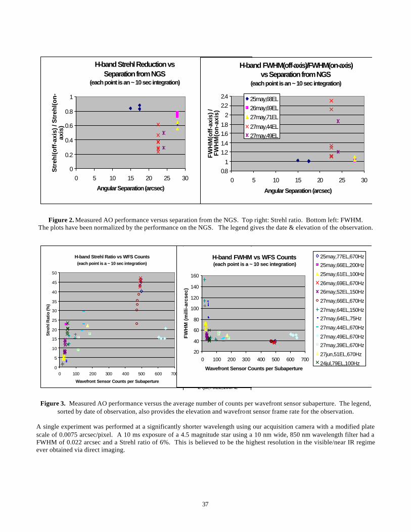
37
Figure 2. Measured AO performance versus separation from the NGS. Top right: Strehl ratio. Bottom left: FWHM.
The plots have been normalized by the performance on the NGS. The legend gives the date & elevation of the observation.
Figure 3. Measured AO performance versus the average number of counts per wavefront sensor subaperture. The legend,
sorted by date of observation, also provides the elevation and wavefront sensor frame rate for the observation.
A single experiment was performed at a significantly shorter wavelength using our acquisition camera with a modified plate scale of 0.0075 arcsec/pixel. A 10 ms exposure of a 4.5 magnitude star using a 10 nm wide, 850 nm wavelength filter had a FWHM of 0.022 arcsec and a Strehl ratio of 6%. This is believed to be the highest resolution in the visible/near IR regime ever obtained via direct imaging.
H-band Strehl Ratio vs WFS Counts (each point is a ~ 10 sec integration)
0
5
10
15
20
25
30
35
40
45
50
0 100 200 300 400 500 600 700
Wavefront Sensor Counts per Subaperture
Str
ehl R
atio
(%)
25may,77EL,670Hz
25may,66EL,200Hz
25may,61EL,100Hz
26may,69EL,670Hz
26may,52EL,150Hz
27may,66EL,670Hz
27may,64EL,150Hz
27may,64EL,75Hz
27may,44EL,670Hz
27may,49EL,670Hz
27may,39EL,670Hz
27jun,51EL,670Hz
24jul,79EL,100Hz
H-band FWHM vs WFS Counts (each point is a ~ 10 sec integration)
20
40
60
80
100
120
140
160
0 100 200 300 400 500 600 700
Wavefront Sensor Counts per Subaperture
FW
HM
(m
illi-
arcs
ec)
25may,77EL,670Hz
25may,66EL,200Hz
25may,61EL,100Hz
26may,69EL,670Hz
26may,52EL,150Hz
27may,66EL,670Hz
27may,64EL,150Hz
27may,64EL,75Hz
27may,44EL,670Hz
27may,49EL,670Hz
27may,39EL,670Hz
27jun,51EL,670Hz
24jul,79EL,100Hz
H-band Strehl Reduction vs Separation from NGS
(each point is an ~ 10 sec integration)
0
0.2
0.4
0.6
0.8
1
0 5 10 15 20 25 30
Angular Separation (arcsec)
Str
ehl(
off
-axi
s) /
Str
ehl(
on
-ax
is)
25may,68EL26may,69EL27may,71EL27may,44EL27may,49EL
H-band FWHM(off-axis)/FWHM(on-axis)vs Separation from NGS
(each point is an ~ 10 sec integration)
0.81
1.21.4
1.61.8
2
2.22.4
0 5 10 15 20 25 30
Angular Separation (arcsec)
FW
HM
(off
-axi
s) /
FW
HM
(on
-axi
s)
25may,68EL26may,69EL27may,71EL
27may,44EL27may,49EL
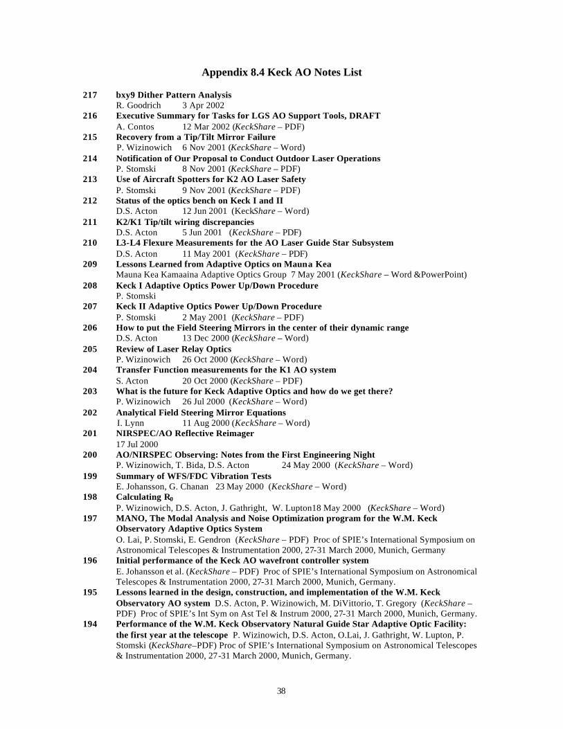
38
Appendix 8.4 Keck AO Notes List
217 bxy9 Dither Pattern Analysis R. Goodrich 3 Apr 2002
216 Executive Summary for Tasks for LGS AO Support Tools, DRAFT A. Contos 12 Mar 2002 (KeckShare – PDF) 215 Recovery from a Tip/Tilt Mirror Failure P. Wizinowich 6 Nov 2001 (KeckShare – Word) 214 Notification of Our Proposal to Conduct Outdoor Laser Operations
P. Stomski 8 Nov 2001 (KeckShare – PDF) 213 Use of Aircraft Spotters for K2 AO Laser Safety
P. Stomski 9 Nov 2001 (KeckShare – PDF) 212 Status of the optics bench on Keck I and II D.S. Acton 12 Jun 2001 (KeckShare – Word) 211 K2/K1 Tip/tilt wiring discrepancies D.S. Acton 5 Jun 2001 (KeckShare – PDF) 210 L3-L4 Flexure Measurements for the AO Laser Guide Star Subsystem D.S. Acton 11 May 2001 (KeckShare – PDF) 209 Lessons Learned from Adaptive Optics on Mauna Kea Mauna Kea Kamaaina Adaptive Optics Group 7 May 2001 (KeckShare – Word &PowerPoint) 208 Keck I Adaptive Optics Power Up/Down Procedure P. Stomski 207 Keck II Adaptive Optics Power Up/Down Procedure P. Stomski 2 May 2001 (KeckShare – PDF) 206 How to put the Field Steering Mirrors in the center of their dynamic range D.S. Acton 13 Dec 2000 (KeckShare – Word) 205 Review of Laser Relay Optics P. Wizinowich 26 Oct 2000 (KeckShare – Word) 204 Transfer Function measurements for the K1 AO system S. Acton 20 Oct 2000 (KeckShare – PDF) 203 What is the future for Keck Adaptive Optics and how do we get there? P. Wizinowich 26 Jul 2000 (KeckShare – Word) 202 Analytical Field Steering Mirror Equations I. Lynn 11 Aug 2000 (KeckShare – Word) 201 NIRSPEC/AO Reflective Reimager
17 Jul 2000 200 AO/NIRSPEC Observing: Notes from the First Engineering Night
P. Wizinowich, T. Bida, D.S. Acton 24 May 2000 (KeckShare – Word) 199 Summary of WFS/FDC Vibration Tests
E. Johansson, G. Chanan 23 May 2000 (KeckShare – Word) 198 Calculating R0 P. Wizinowich, D.S. Acton, J. Gathright, W. Lupton18 May 2000 (KeckShare – Word) 197 MANO, The Modal Analysis and Noise Optimization program for the W.M. Keck
Observatory Adaptive Optics System O. Lai, P. Stomski, E. Gendron (KeckShare – PDF) Proc of SPIE’s International Symposium on Astronomical Telescopes & Instrumentation 2000, 27-31 March 2000, Munich, Germany
196 Initial performance of the Keck AO wavefront controller system E. Johansson et al. (KeckShare – PDF) Proc of SPIE’s International Symposium on Astronomical Telescopes & Instrumentation 2000, 27-31 March 2000, Munich, Germany.
195 Lessons learned in the design, construction, and implementation of the W.M. Keck Observatory AO system D.S. Acton, P. Wizinowich, M. DiVittorio, T. Gregory (KeckShare – PDF) Proc of SPIE’s Int Sym on Ast Tel & Instrum 2000, 27-31 March 2000, Munich, Germany.
194 Performance of the W.M. Keck Observatory Natural Guide Star Adaptive Optic Facility: the first year at the telescope P. Wizinowich, D.S. Acton, O.Lai, J. Gathright, W. Lupton, P. Stomski (KeckShare–PDF) Proc of SPIE’s International Symposium on Astronomical Telescopes & Instrumentation 2000, 27-31 March 2000, Munich, Germany.
39
193 Vibration Meeting Results (17-18 Nov meeting) P. Wizinowich 4 Jan 2000 (KeckShare – Word) 192 Vibration Meeting Presentation Materials (LLNL) (17-18 Nov meeting)
E. Johansson 17 Nov 1999 (KeckShare – PowerPoint) 191 Vibration Meeting Presentation Materials (CARA) P. Wizinowich 4 Jan 2000 (KeckShare – PowerPoint) 190 NIRSPEC AO Reimager
Peter Wizinowich 22 Nov 99 (KeckShare – Word) 189 AO for OAs
William Lupton 24 Sep 1999 188 Acceptance Review Committee Report, Keck II NGS AO Facility
7 Sep 1999 (KeckShare – Word) 187 Keck II NGS AO Facility Acceptance Review Presentation
30 Aug 1999 (KeckShare – PowerPoint) 186 Revised Plan for Laser Subsystem Completion
C. Shelton, D. Pennington 16 Sep 1999 185 Adaptive Optics Task List
P. Wizinowich 26 Aug 99 (KeckShare – Word) 184 Keck Adaptive Optics Facility Hardware Manual #1, Nasmyth Platform (DRAFT)
16 Aug 99 (KeckShare – Word) 183 Report of the Review Committee; Keck II AO Facility ; NGS AO Readiness Review
Review Committee, R.Q. Fugate, chair 22 Jan 98, revised 2 Jan 99 (KeckShare – Word&PDF) 182 Characterization of the lenslet arrays. ( DRAFT )
D. Scott Acton 13 May 99 (rev. 9/2/99) (KeckShare --PDF) 181 Tip / tilt performance measurements
D. Scott Acton 13 May 99 (KeckShare --PDF) 180 Yag Timing System Programmer's Guide 179 Computer Control System and Software 178 Wavefront Controller Subsystem
H. Jones 05 May 99 177 DM Controller Interface Description
Erik Johansson 19 Mar 99 176 Keck II Adaptive Optics Facility NGS AO Readiness Review
19 Jan 99 (KeckShare --PDF) 175 Servo Control of the Movable Stages using PMAC Controllers for the W.M. Keck Telescope
Adaptive Optics System Kevin Ho, Paul Stomski, Mark Sirota, KevinTsubota 20 Mar 98 174 First Sky Tests of KCAM with the AO Science Path
Peter Wizinowich 11 Jan 99 (Keck Share – Word) 173 Keck Adaptive Optics Program Status Report Peter Wizinowich 13 Nov 98 (KeckShare – PDF & Word) 172 WFC System Upgrades CARA & LLNL 11 Nov 98 171 Phased Plan for Laser Subsystem Completion, Integration and Test Peter Wizinowich, Chris Shelton 14 Dec 98 (KeckShare – Word) 170 Center of Rotation of the El -bearings on Keck II
D. Scott Acton, Michael DiVittorio 21 Oct 98 (KeckShare – PDF) 169 Mauna Kea Laser Guide Star Technical Working Group Report to the Mauna Kea Users
Peter Wizinowich 24 Sep 98 168 Calculating AO Control Matrices
Paul Stomski 19 Oct 98 167 AO WFC File Naming and Format Conventions
Paul Stomski 19 Oct 98 166 Adaptive Optics Science Team Workshop
Peter Wizinowich 06 Oct 98 (KeckShare – PDF) 165 Issues related to the location of the Keck I Adaptive Optics Bench.
Peter Wizinowich 31Aug 98 (KeckShare – Word)
40
164 Modal control: a primer. Olivier Lai {16Jul98}
163 Wavefront controller subsystem pre-ship review. Peter Wizinowich, D. Scott Acton, Paul Stomski 07Jul98
162 Design and performance of the tip-tilt subsystem for the Keck II telescope AO system. K. Avicola, J. Watson, B. Beeman, T. Kuklo, and J. Taylor Proceedings of SPIE Astronomical Telescopes & Instrumentation Conference, 20-28 March 1998, Kona, Hawaii. (KeckShare – PDF)
161 The wavefront control system for the Keck Telescope J.M. Brase, J. An, K. Avicola, et.al. Proceedings of SPIE Astronomical Telescopes & Instrumentation Conference, 20- 28 March 1998, Kona, Hawaii. (KeckShare – Word)
160 WFC Keywords (KeckShare – PDF ) 159 AO Supervisory Control Subsystem Review
William Lupton 29May98 158 OBS FSM Coordinated Moves
Kevin Tsubota, Paul Stomski 07 May 98 157 OBS Keyword Description
Kevin Tsubota, Paul Stomski 07 May 98 156 Engineering Science with Keck AO
Olivier Lai 05 May 98 155 Status of the W.M. Keck Observatory Adaptive Optics Facility
Peter Wizinowich, D. Scott Acton, Thomas Gregory, Paul Stomski, Jong An, Ken Avicola, Jim Brase, Herb Friedman, Don Gavel, Claire Max Proceedings of SPIE Astronomical Telescopes & Instrumentation Conference, 20- 28 March 1998, Kona, Hawaii.
154 Laboratory Calibration of the W.M. Keck Observatory Adaptive Optics Facility D. Scott Acton, Peter Wizinowich, Paul Stomski, Chris Shelton, Olivier Lai, J. Brase Proceedings of SPIE Astronomical Telescopes & Instrumentation Conference, 20-28 Mar 1998, Kona, Hawaii.
153 Coordination and Use of Laser Beacons for Adaptive Optics on Mauna Kea Peter Wizinowich, Doug Simons, Hideki Takami, Christian Veillet, and Richard Wainscoat. (KeckShare – Word) Proc of SPIE Ast Tel & Instrum Conf, 20- 28 March 1998, Kona, Hawaii.
152 Optics Bench Subsystem Review Peter Wizinowich, Paul Stomski, D. Scott Acton 09 Apr 98 (KeckShare – PDF & Word)
151 Comments on Program Status Report, KAON 150 Claire Max 13 Mar 98 (KeckShare – Word)
150 Keck Adaptive Optics Program Status Report Peter Wizinowich 10 Mar 98 (KeckShare – Word)
149 Implementation of KCAM with the AO Facility Peter Wizinowich, James Larkin 16 Jan 97 (KeckShare – PDF)
148 Laser Subsystem Pre-Ship Review Peter Wizinowich, D. Scott Acton 25 Feb 98 (KeckShare – PDF & Word)
147 Subsystem Completion, Integration and Test Peter Wizinowich 15 Feb 98
146 Neutral Density and Color Filters for the Wavefront Sensor Peter Wizinowich 9 Feb 98 (KeckShare – Word)
145 Setting up the Laser Subsystem at Keck Headquarters Peter Wizinowich 27 Jan 98
144 Laser Deliverables and Acceptance Testing Chris Shelton, Peter Wizinowich, Paul Stomski 10 Dec 97 revised 11 Feb 98
143 Low Bandwidth Wavefront Sensor Optical Design Peter Wizinowich 12 Dec 97
142 Keck Adaptive Optics Program Status Report Peter Wizinowich 12 Nov 97 (KeckShare – Word)
141 Mauna Kea Laser Guide Star Technical Working Group Report to the Mauna Kea Directors and Users Peter Wizinowich 25 Sep 97
140 AO Supervisory Control William Lupton 17 Sep 97
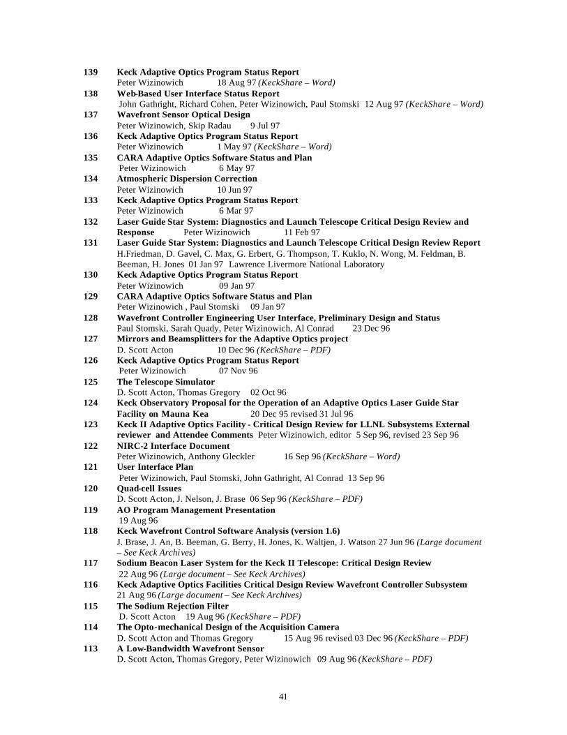
41
139 Keck Adaptive Optics Program Status Report Peter Wizinowich 18 Aug 97 (KeckShare – Word)
138 Web-Based User Interface Status Report John Gathright, Richard Cohen, Peter Wizinowich, Paul Stomski 12 Aug 97 (KeckShare – Word)
137 Wavefront Sensor Optical Design Peter Wizinowich, Skip Radau 9 Jul 97
136 Keck Adaptive Optics Program Status Report Peter Wizinowich 1 May 97 (KeckShare – Word)
135 CARA Adaptive Optics Software Status and Plan Peter Wizinowich 6 May 97
134 Atmospheric Dispersion Correction Peter Wizinowich 10 Jun 97
133 Keck Adaptive Optics Program Status Report Peter Wizinowich 6 Mar 97
132 Laser Guide Star System: Diagnostics and Launch Telescope Critical Design Review and Response Peter Wizinowich 11 Feb 97
131 Laser Guide Star System: Diagnostics and Launch Telescope Critical Design Review Report H.Friedman, D. Gavel, C. Max, G. Erbert, G. Thompson, T. Kuklo, N. Wong, M. Feldman, B. Beeman, H. Jones 01 Jan 97 Lawrence Livermore National Laboratory
130 Keck Adaptive Optics Program Status Report Peter Wizinowich 09 Jan 97
129 CARA Adaptive Optics Software Status and Plan Peter Wizinowich , Paul Stomski 09 Jan 97
128 Wavefront Controller Engineering User Interface, Preliminary Design and Status Paul Stomski, Sarah Quady, Peter Wizinowich, Al Conrad 23 Dec 96
127 Mirrors and Beamsplitters for the Adaptive Optics project D. Scott Acton 10 Dec 96 (KeckShare – PDF)
126 Keck Adaptive Optics Program Status Report Peter Wizinowich 07 Nov 96
125 The Telescope Simulator D. Scott Acton, Thomas Gregory 02 Oct 96
124 Keck Observatory Proposal for the Operation of an Adaptive Optics Laser Guide Star Facility on Mauna Kea 20 Dec 95 revised 31 Jul 96
123 Keck II Adaptive Optics Facility - Critical Design Review for LLNL Subsystems External reviewer and Attendee Comments Peter Wizinowich, editor 5 Sep 96, revised 23 Sep 96
122 NIRC-2 Interface Document Peter Wizinowich, Anthony Gleckler 16 Sep 96 (KeckShare – Word)
121 User Interface Plan Peter Wizinowich, Paul Stomski, John Gathright, Al Conrad 13 Sep 96
120 Quad-cell Issues D. Scott Acton, J. Nelson, J. Brase 06 Sep 96 (KeckShare – PDF)
119 AO Program Management Presentation 19 Aug 96
118 Keck Wavefront Control Software Analysis (version 1.6) J. Brase, J. An, B. Beeman, G. Berry, H. Jones, K. Waltjen, J. Watson 27 Jun 96 (Large document – See Keck Archives)
117 Sodium Beacon Laser System for the Keck II Telescope: Critical Design Review 22 Aug 96 (Large document – See Keck Archives)
116 Keck Adaptive Optics Facilities Critical Design Review Wavefront Controller Subsystem 21 Aug 96 (Large document – See Keck Archives)
115 The Sodium Rejection Filter D. Scott Acton 19 Aug 96 (KeckShare – PDF)
114 The Opto-mechanical Design of the Acquisition Camera D. Scott Acton and Thomas Gregory 15 Aug 96 revised 03 Dec 96 (KeckShare – PDF)
113 A Low-Bandwidth Wavefront Sensor D. Scott Acton, Thomas Gregory, Peter Wizinowich 09 Aug 96 (KeckShare – PDF)
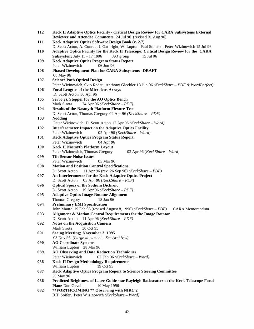
42
112 Keck II Adaptive Optics Facility - Critical Design Review for CARA Subsystems External Reviewer and Attendee Comments 24 Jul 96 (revised 01 Aug 96)
111 Keck Adaptive Optics Software Design Book (v. 2.7) D. Scott Acton, A. Conrad, J. Gathright, W. Lupton, Paul Stomski, Peter Wizinowich 15 Jul 96
110 Adaptive Optics Facility for the Keck II Telescope: Critical Design Review for the CARA Subsystem, July 15 - 17 1996 AO group 15 Jul 96
109 Keck Adaptive Optics Program Status Report Peter Wizinowich 06 Jun 96
108 Phased Development Plan for CARA Subsystems - DRAFT 08 May 96
107 Science Path Optical Design Peter Wizinowich, Skip Radau, Anthony Gleckler 18 Jun 96 (KeckShare – PDF & WordPerfect)
106 Focal Lengths of the Microlens Arrays D. Scott Acton 30 Apr 96
105 Servo vs. Stepper for the AO Optics Bench Mark Sirota 24 Apr 96 (KeckShare – PDF)
104 Results of the Nasmyth Platform Flexure Test D. Scott Acton, Thomas Gregory 02 Apr 96 (KeckShare – PDF)
103 Nodding Peter Wizinowich, D. Scott Acton 12 Apr 96 (KeckShare – Word)
102 Interferometer Impact on the Adaptive Optics Facility Peter Wizinowich 05 Apr 96 (KeckShare – Word)
101 Keck Adaptive Optics Program Status Report Peter Wizinowich 04 Apr 96
100 Keck II Nasmyth Platform Layout Peter Wizinowich, Thomas Gregory 02 Apr 96 (KeckShare – Word)
099 Tilt Sensor Noise Issues Peter Wizinowich 05 Mar 96
098 Motion and Position Control Specifications D. Scott Acton 11 Apr 96 (rev. 26 Sep 96) (KeckShare – PDF)
097 An Interferometer for the Keck Adaptive Optics Project D. Scott Acton 05 Apr 96 (KeckShare – PDF)
096 Optical Specs of the Sodium Dichroic D. Scott Acton 19 Apr 96 (KeckShare – PDF)
095 Adaptive Optics Image Rotator Alignment Thomas Gregory 18 Jan 96
094 Preliminary EMI Specification John Maute 19 Feb 96 (revised August 8, 1996) (KeckShare – PDF) CARA Memorandum
093 Alignment & Motion Control Requirements for the Image Rotator D. Scott Acton 11 Apr 96 (KeckShare – PDF)
092 Notes on the Acquisition Camera Mark Sirota 30 Oct 95
091 Seeing Meeting; November 3, 1995 03 Nov 95 (Large document – See Archives)
090 AO Coordinate Systems William Lupton 28 Mar 96
089 AO Observing and Data Reduction Techniques Peter Wizinowich 02 Feb 96 (KeckShare – Word)
088 Keck II Design Methodology Requirements William Lupton 19 Oct 95
087 Keck Adaptive Optics Program Report to Science Steering Committee 20 May 96
086 Predicted Brightness of Laser Guide star Rayleigh Backscatter at the Keck Telescope Focal Plane Don Gavel 10 May 1996
082 **FORTHCOMING ** Observing with NIRC 2 B.T. Soifer, Peter W izinowich (KeckShare – Word)
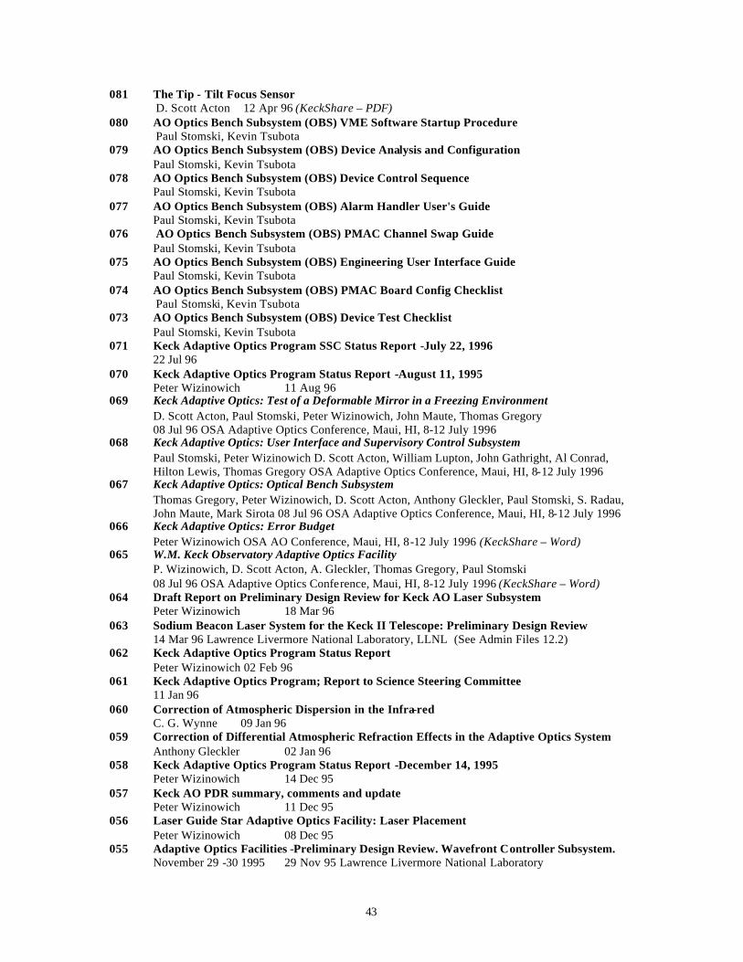
43
081 The Tip - Tilt Focus Sensor D. Scott Acton 12 Apr 96 (KeckShare – PDF)
080 AO Optics Bench Subsystem (OBS) VME Software Startup Procedure Paul Stomski, Kevin Tsubota
079 AO Optics Bench Subsystem (OBS) Device Analysis and Configuration Paul Stomski, Kevin Tsubota
078 AO Optics Bench Subsystem (OBS) Device Control Sequence Paul Stomski, Kevin Tsubota
077 AO Optics Bench Subsystem (OBS) Alarm Handler User's Guide Paul Stomski, Kevin Tsubota
076 AO Optics Bench Subsystem (OBS) PMAC Channel Swap Guide Paul Stomski, Kevin Tsubota
075 AO Optics Bench Subsystem (OBS) Engineering User Interface Guide Paul Stomski, Kevin Tsubota
074 AO Optics Bench Subsystem (OBS) PMAC Board Config Checklist Paul Stomski, Kevin Tsubota
073 AO Optics Bench Subsystem (OBS) Device Test Checklist Paul Stomski, Kevin Tsubota
071 Keck Adaptive Optics Program SSC Status Report -July 22, 1996 22 Jul 96
070 Keck Adaptive Optics Program Status Report -August 11, 1995 Peter Wizinowich 11 Aug 96
069 Keck Adaptive Optics: Test of a Deformable Mirror in a Freezing Environment D. Scott Acton, Paul Stomski, Peter Wizinowich, John Maute, Thomas Gregory 08 Jul 96 OSA Adaptive Optics Conference, Maui, HI, 8-12 July 1996
068 Keck Adaptive Optics: User Interface and Supervisory Control Subsystem Paul Stomski, Peter Wizinowich D. Scott Acton, William Lupton, John Gathright, Al Conrad, Hilton Lewis, Thomas Gregory OSA Adaptive Optics Conference, Maui, HI, 8-12 July 1996
067 Keck Adaptive Optics: Optical Bench Subsystem Thomas Gregory, Peter Wizinowich, D. Scott Acton, Anthony Gleckler, Paul Stomski, S. Radau, John Maute, Mark Sirota 08 Jul 96 OSA Adaptive Optics Conference, Maui, HI, 8-12 July 1996
066 Keck Adaptive Optics: Error Budget Peter Wizinowich OSA AO Conference, Maui, HI, 8-12 July 1996 (KeckShare – Word)
065 W.M. Keck Observatory Adaptive Optics Facility P. Wizinowich, D. Scott Acton, A. Gleckler, Thomas Gregory, Paul Stomski 08 Jul 96 OSA Adaptive Optics Conference, Maui, HI, 8-12 July 1996 (KeckShare – Word)
064 Draft Report on Preliminary Design Review for Keck AO Laser Subsystem Peter Wizinowich 18 Mar 96
063 Sodium Beacon Laser System for the Keck II Telescope: Preliminary Design Review 14 Mar 96 Lawrence Livermore National Laboratory, LLNL (See Admin Files 12.2)
062 Keck Adaptive Optics Program Status Report Peter Wizinowich 02 Feb 96
061 Keck Adaptive Optics Program; Report to Science Steering Committee 11 Jan 96
060 Correction of Atmospheric Dispersion in the Infra-red C. G. Wynne 09 Jan 96
059 Correction of Differential Atmospheric Refraction Effects in the Adaptive Optics System Anthony Gleckler 02 Jan 96
058 Keck Adaptive Optics Program Status Report -December 14, 1995 Peter Wizinowich 14 Dec 95
057 Keck AO PDR summary, comments and update Peter Wizinowich 11 Dec 95
056 Laser Guide Star Adaptive Optics Facility: Laser Placement Peter Wizinowich 08 Dec 95
055 Adaptive Optics Facilities -Preliminary Design Review. Wavefront Controller Subsystem. November 29 -30 1995 29 Nov 95 Lawrence Livermore National Laboratory
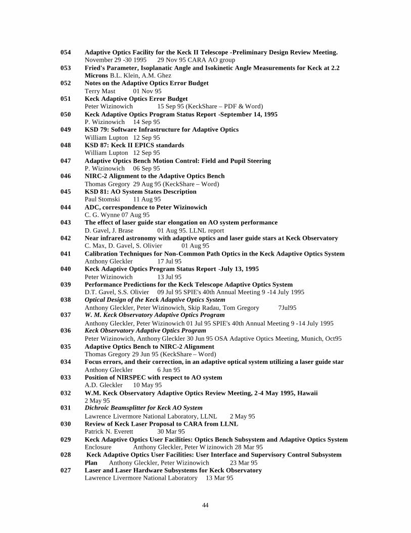
44
054 Adaptive Optics Facility for the Keck II Telescope -Preliminary Design Review Meeting. November 29 -30 1995 29 Nov 95 CARA AO group
053 Fried's Parameter, Isoplanatic Angle and Isokinetic Angle Measurements for Keck at 2.2 Microns B.L. Klein, A.M. Ghez
052 Notes on the Adaptive Optics Error Budget Terry Mast 01 Nov 95
051 Keck Adaptive Optics Error Budget Peter Wizinowich 15 Sep 95 (KeckShare – PDF & Word)
050 Keck Adaptive Optics Program Status Report -September 14, 1995 P. Wizinowich 14 Sep 95
049 KSD 79: Software Infrastructure for Adaptive Optics William Lupton 12 Sep 95
048 KSD 87: Keck II EPICS standards William Lupton 12 Sep 95
047 Adaptive Optics Bench Motion Control: Field and Pupil Steering P. Wizinowich 06 Sep 95
046 NIRC-2 Alignment to the Adaptive Optics Bench Thomas Gregory 29 Aug 95 (KeckShare – Word)
045 KSD 81: AO System States Description Paul Stomski 11 Aug 95
044 ADC, correspondence to Peter Wizinowich C. G. Wynne 07 Aug 95
043 The effect of laser guide star elongation on AO system performance D. Gavel, J. Brase 01 Aug 95. LLNL report
042 Near infrared astronomy with adaptive optics and laser guide stars at Keck Observatory C. Max, D. Gavel, S. Olivier 01 Aug 95
041 Calibration Techniques for Non-Common Path Optics in the Keck Adaptive Optics System Anthony Gleckler 17 Jul 95
040 Keck Adaptive Optics Program Status Report -July 13, 1995 Peter Wizinowich 13 Jul 95
039 Performance Predictions for the Keck Telescope Adaptive Optics System D.T. Gavel, S.S. Olivier 09 Jul 95 SPIE's 40th Annual Meeting 9 -14 July 1995
038 Optical Design of the Keck Adaptive Optics System Anthony Gleckler, Peter Wizinowich, Skip Radau, Tom Gregory 7Jul95
037 W. M. Keck Observatory Adaptive Optics Program Anthony Gleckler, Peter Wizinowich 01 Jul 95 SPIE's 40th Annual Meeting 9 -14 July 1995
036 Keck Observatory Adaptive Optics Program Peter Wizinowich, Anthony Gleckler 30 Jun 95 OSA Adaptive Optics Meeting, Munich, Oct95
035 Adaptive Optics Bench to NIRC-2 Alignment Thomas Gregory 29 Jun 95 (KeckShare – Word)
034 Focus errors, and their correction, in an adaptive optical system utilizing a laser guide star Anthony Gleckler 6 Jun 95
033 Position of NIRSPEC with respect to AO system A.D. Gleckler 10 May 95
032 W.M. Keck Observatory Adaptive Optics Review Meeting, 2-4 May 1995, Hawaii 2 May 95
031 Dichroic Beamsplitter for Keck AO System Lawrence Livermore National Laboratory, LLNL 2 May 95
030 Review of Keck Laser Proposal to CARA from LLNL Patrick N. Everett 30 Mar 95
029 Keck Adaptive Optics User Facilities: Optics Bench Subsystem and Adaptive Optics System Enclosure Anthony Gleckler, Peter W izinowich 28 Mar 95
028 Keck Adaptive Optics User Facilities: User Interface and Supervisory Control Subsystem Plan Anthony Gleckler, Peter Wizinowich 23 Mar 95
027 Laser and Laser Hardware Subsystems for Keck Observatory Lawrence Livermore National Laboratory 13 Mar 95
45
026 Wavefront Controller Subsystem for Keck Adaptive Optics Lawrence Livermore National Laboratory 28 Feb 95
025 Near Infrared Atmospheric Characterization at Keck Andrea Ghez Date: 28 Feb 95
024 Keck Adaptive Optics Wavefront Controller: Proposal No. 70-4140 Jet Propulsion Laboratory 28 Feb 95
023 Near Infrared Image Motion and Differential Motion at Keck Beth Klein and Andrea Ghez 28 Feb 95 UCLA , Dept. of Physics and Astrophysics
022 Documentation for Adaptive Optics Subsystems P. Wizinowich 07 Feb 95
021 Conceptual Design Meeting: Keck AO Facilities II and III 07 Dec 94
020 Atmospheric Characterization for Adaptive Optics Gary Chanan 06 Dec 94
019 Guidelines for Keck Adaptive Optics Subsystem Proposals Peter Wizinowich 05 Dec 94
018 Keck AO Program Preliminary Schedule and Budget P. Wizinowich 23 Nov 94
017 LLNL f/15 Adaptive Optics Layout UCRL-JC-119371 J.T. Salmon 23 Nov 94
016 System Architecture and Subsystem Definitions for Keck AO System Anthony Gleckler, Peter Wizinowich 11 Nov 94
015 Wavefront Reconstructor Information A.D. Gleckler 28 Oct 94
014 Layout alternatives for the AO system A.D Gleckler, P. Wizinowich 13 Oct 94
013 Evaluation of the f/15 and f/40 secondary mirror options for the AO facilities A. D. Gleckler, P. Wizinowich, S. Radau 03 Oct 94
012 Adaptive Optics for Keck Observatory Keck Staff and California Community 01 Sep 94
011 Report on Measured Image Motion on the Keck Telescope Anthony Gleckler 01 Jun 94
010 Adaptive Optics Facility I Design Review April 28, 1994 28 Apr 94
009 High Speed Seeing Measurements at the Keck Telescope F. Dekens, D. Kirkman, G. Chanan, T. Mast, J. Nelson, G. Illingworth, P. Wizinowich 3 Mar 94 SPIE vol. 2201 Adaptive Optics in Astronomy.
008 Issues in the Design and Optimization of Adaptive Optics and Laser Guide Stars for the Keck Telescopes C. Max, D. Gavel, S. Olivier, J. Brase, H. Friedman, K. Avicola, J. Salmon, A. Gleckler, T. Mast, J. Nelson, P. Wizinowich 01 Mar 94 SPIE vol. 2201 AO in Astronomy.
007 W.M. Keck Observatory Adaptive Optics Program Peter Wizinowich, Jerry Nelson, Terry Mast, Anthony Gleckler 01 Mar 94 SPIE vol. 2201 Adaptive Optics in Astronomy.
006 Atmospheric-Seeing Data Analysis Terry Mast (editor), Bill Bradford, Jim Brase, Frank Dekens, Don Gavel, Tony Gleckler, Jerry Nelson, Scot Olivier, Peter Wizinowich 01 Jan 94
005 Calculating atmospheric parameters from image motion P. Wizinowich 16 Nov 93
004 Atmospheric Characterization P. Wizinowich, A. Gleckler 16 Nov 93
003 Keck Seeing Monitor (KSM) User Manual Gary Chanan, David Kirkman 15 Sep 93
002 Keck Adaptive Optics: Predicted Performance for Low Order Correction Peter Wizinowich 18 Mar 93
001 The Adaptive Optics Program for Keck Observatory The Adaptive Optics Working Group 01 Oct 92
46
Appendix 8.5 Keck AO Error Budget The NGS AO image improvement requirement from KOR 208, section 5.4.2, is:
"When using a bright, on-axis reference star the facility must reduce the atmospheric wavefront errors and the errors internal to the facility, as delivered to the science instrument entrance window, in order to achieve a Strehl ratio >= exp[-(2*pi*sigma/lambda)^2] over the optimized wavelength range, where the rms wavefront error, sigma, is 70 nm under the Set A seeing conditions and at the zenith 140 nm under the Set B seeing conditions and a zenith angle of 30 deg 400 nm under the Set C seeing conditions and a zenith angle of 60 deg The facility must reduce the sum of the static segment warping harness residuals, the segment stacking errors and the science instrument aberrations, assuming the optimized telescope aberrations shown in Table 5-3, to less than 70 nm rms wavefront. The facility is not expected to deal with segment piston errors, segment vibration errors or ACS noise errors. The wavefront sensor noise and quantum efficiency must not reduce the signal-to-noise ration to less than 10, assuming 400 incident photons per subaperture, and a 100 ms integration."
The uncorrectable segment piston, segment vibration and ACS noise errors were assumed to be 82 nm in KOR 208. The numbers above correspond to a requirement of a best H-band Strehl of >= exp[-(2*pi*(0.070^2+0.070^2+0.082^2)^0.5/1.65)^2] = 0.79 and a median H-band Strehl of >= 0.64 (for an infinitely bright star). KAON 051 discusses the error budget for the Keck AO system. The error budget spreadsheet, originally presented in this KAON, has been updated to reflect what we currently believe we know about the AO system (still with lots of assumptions as well). This revised error budget is provided as an attachment.
AOERROR.XLS
This error budget predicts a best Strehl at H of 0.48 and a median of 0.33 (again for bright stars). This is reasonably close to our performance (at least back in 1999). The major changes in this new error budget with respect to the initial error budget are the following: • The measured tip/tilt and higher order closed loop bandwidths have been used. • A bright, but not infinitely bright, NGS is used. • A term has been added to the spot size measurement error to include the current aberrations of the
wavefront sensor optics. • The warping residuals and segment vibrations are assumed to be higher than the values given in KOR
208. • Some uncorrected science instrument aberrations are included. The top contributors to Strehl reduction under the best seeing conditions are the measurement error due to spot size and the segment vibration errors. Two similar sized errors also contribute to the Strehl reduction under median seeing conditions, namely fitting and bandwidth errors. All but the fitting error could potentially be improved for our existing system.