kat-7/meerkat commissioning
DESCRIPTION
KAT-7/MeerKAT Commissioning. SPT and Commissioning teams * http://public.ska.ac.za/kat-7/kat-7-operations. - PowerPoint PPT PresentationTRANSCRIPT
KAT-7/MeerKAT Commissioning
SPT and Commissioning teams *http://public.ska.ac.za/kat-7/kat-7-operations
* Bennett, T., Blose, S., Booth, R., de Villiers, M., Dikgale, A., Foley, T., Frank, B., Goedhart, S., Hess, K., Horrell, J., Lucero, D., Magnus, L., Mauch, T., Nemalili, T., Oozeer, N., Passmoor, S., Ratcliffe, S., Richter, L., Schwardt, L., Smirnov, O., Spann, R., Williams, L., Wilson, S., Wolleben, M., Zwart, J.,
Overview
• The commissioning plan• The Single-dish Continuum Analysis
PackagE SCAPE• Work done so far• Science verification process
Industrial commissioning• High priority early in the project to document
procedures that will be repeated often. PnP mentality
• Verification procedures will be built upon the foundations of previous procedures.
• Multiple commissioning teams will be implemented.
• Operations will be handled by a distinct set of personnel who then become responsible for operations and maintenance.
MeerKAT rollout
• 2014 - install test and commission 6 antennas
• 2015 - 29 antenna at about 3 per month • 2016 - 29 in 8 months at about 4 per
month• Basic rule ... don't' panic
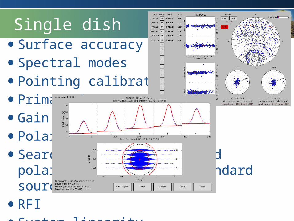
Single dish• Surface accuracy• Spectral modes• Pointing calibration• Primary beam• Gain calibration• Polarisation• Search for unpolarized and polarized, but
stable standard sources• RFI• System linearity
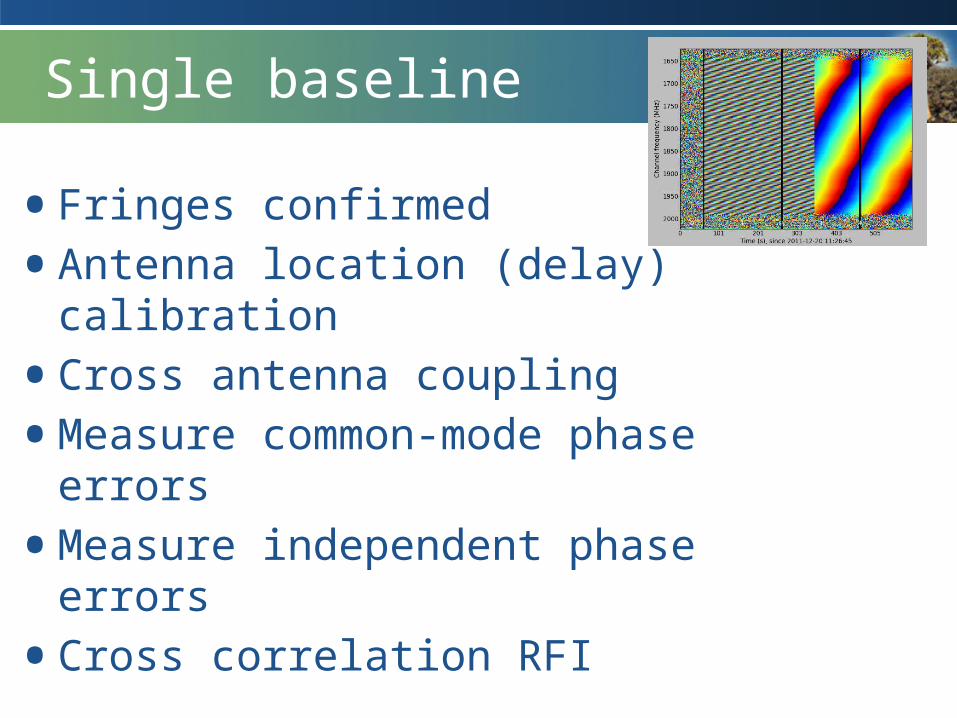
Single baseline
• Fringes confirmed• Antenna location (delay) calibration• Cross antenna coupling• Measure common-mode phase errors• Measure independent phase errors• Cross correlation RFI
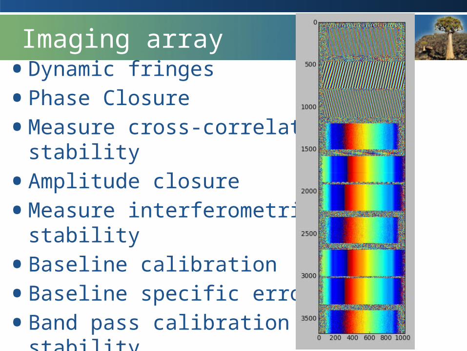
Imaging array• Dynamic fringes • Phase Closure• Measure cross-correlation phase stability• Amplitude closure• Measure interferometric gain stability• Baseline calibration • Baseline specific errors• Band pass calibration and stability • Absolute flux calibration• Interferometric polarisation and calibration

Science verification• Track commissioning parameters with time• Imaging tests with a range of spectral resolutions,
source complexity, brightness, in single-field interferometric mode, Dynamic range, Reproducibility, Noise level
• Mosaicing• Polarization• Fine tune observation procedures• Calibrator surveys• Spectral mode imaging, beamformer and VLBI still
to be confirmed
SCAPE
• In-house suite of reduction software that is used to commission either a single dish or single baseline developed by L Schwardt
• Functionality includeso basic h5 data extraction, simple data plotting
including time series, spectra, spectrograms, beam fits, noise diode based temperature calibrations, fringe plotting, baseline fitting (position and delay), pointing model determination, basic RFI detection, source catalogues, as well as a whole suite of mathematical tools packaged together for ease of use.
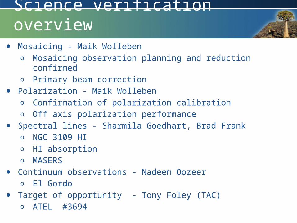
Science verification overview• Mosaicing - Maik Wolleben
o Mosaicing observation planning and reduction confirmedo Primary beam correction
• Polarization - Maik Wollebeno Confirmation of polarization calibrationo Off axis polarization performance
• Spectral lines - Sharmila Goedhart, Brad Franko NGC 3109 HIo HI absorptiono MASERS
• Continuum observations - Nadeem Oozeero El Gordo
• Target of opportunity - Tony Foley (TAC)o ATEL #3694
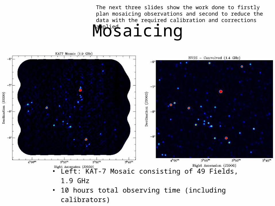
Mosaicing
• Left: KAT-7 Mosaic consisting of 49 Fields, 1.9 GHz• 10 hours total observing time (including calibrators)• Right: NVSS at 1.4 GHz shown for comparison
The next three slides show the work done to firstly plan mosaicing observations and second to reduce the data with the required calibration and corrections applied.
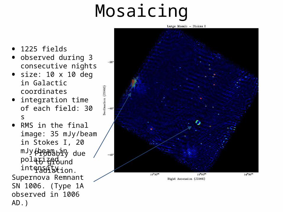
Mosaicing
• 1225 fields• observed during 3
consecutive nights • size: 10 x 10 deg in
Galactic coordinates• integration time of each
field: 30 s• RMS in the final image:
35 mJy/beam in Stokes I, 20 mJy/beam in polarized intensity.
Supernova Remnant SN 1006. (Type 1A observed in 1006 AD.)
Probably due to ground radiation.
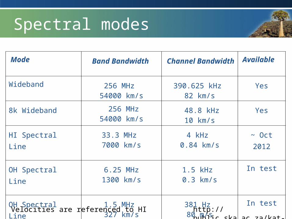
Spectral modes
Mode Band Bandwidth Channel Bandwidth
Available
Wideband 256 MHz 54000 km/s
390.625 kHz 82 km/s
Yes
8k Wideband 256 MHz54000 km/s
48.8 kHz10 km/s
Yes
HI Spectral Line 33.3 MHz 7000 km/s
4 kHz 0.84 km/s
~ Oct 2012
OH Spectral Line 6.25 MHz1300 km/s
1.5 kHz 0.3 km/s
In test
OH Spectral Line 1.5 MHz 327 km/s
381 Hz 80 m/s
In test
http://public.ska.ac.za/kat-7Velocities are referenced to HI
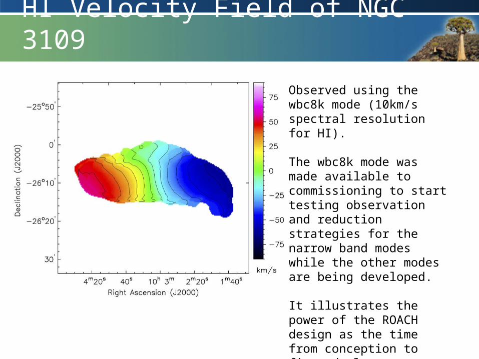
HI Velocity Field of NGC 3109
Observed using the wbc8k mode (10km/s spectral resolution for HI).
The wbc8k mode was made available to commissioning to start testing observation and reduction strategies for the narrow band modes while the other modes are being developed.
It illustrates the power of the ROACH design as the time from conception to first deployment was one day.
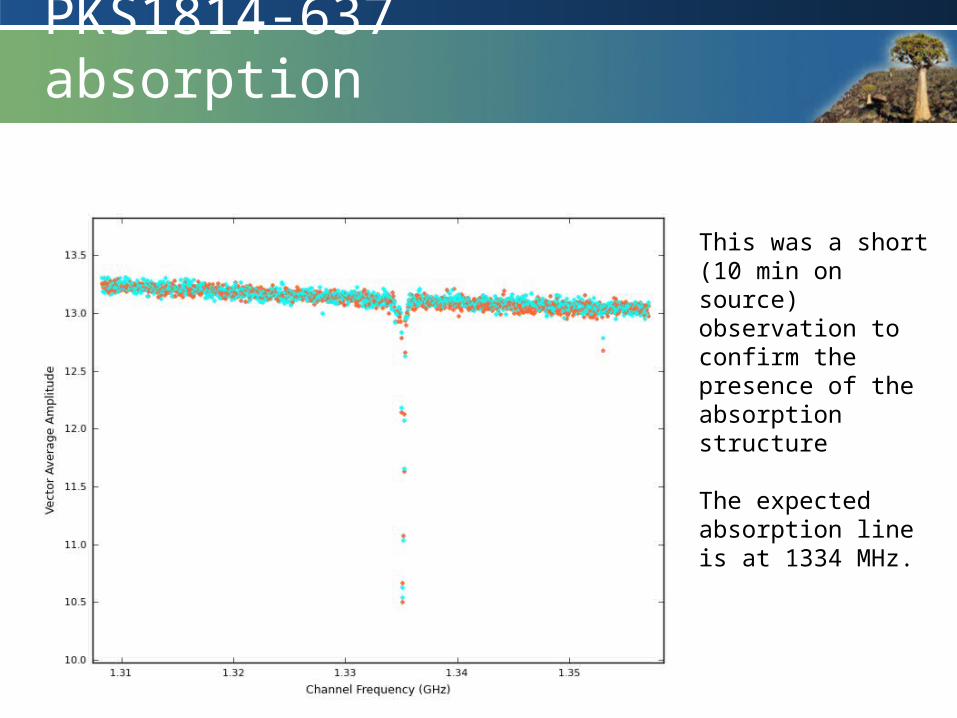
PKS1814-637 absorption
This was a short (10 min on source) observation to confirm the presence of the absorption structure
The expected absorption line is at 1334 MHz.
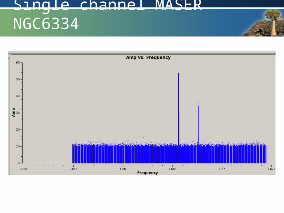
Single channel MASER NGC6334
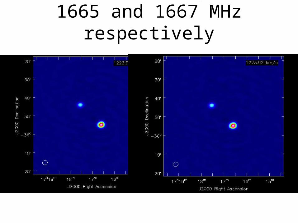
Images (line maps) at 1665 and 1667 MHz respectively
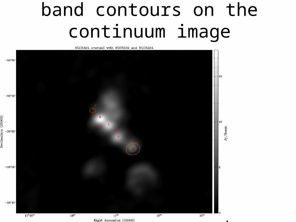
Overlay of the narrow band contours on the continuum image
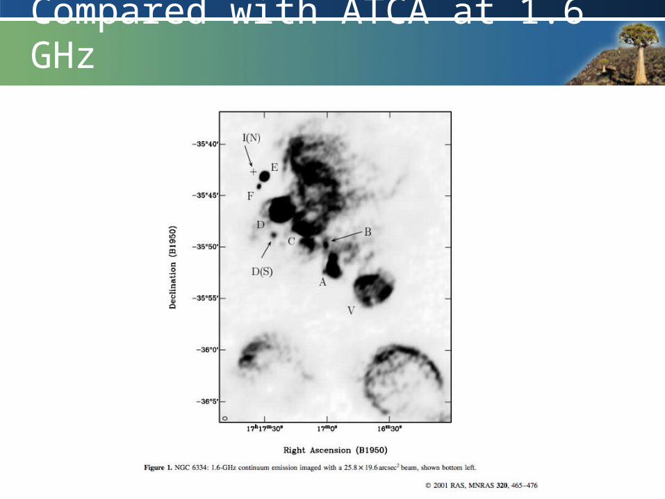
Compared with ATCA at 1.6 GHz
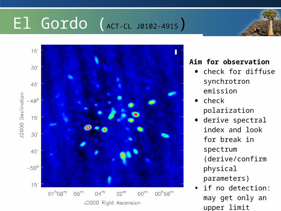
Aim for observation• check for diffuse
synchrotron emission• check polarization• derive spectral index
and look for break in spectrum (derive/confirm physical parameters)
• if no detection: may get only an upper limit
• check expected rms using long integration.
El Gordo (ACT-CL J0102-4915)
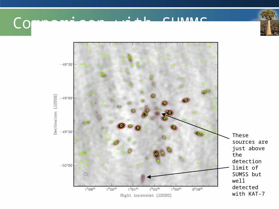
Comparison with SUMMS
These sources are just above the detection limit of SUMSS but well detected with KAT-7
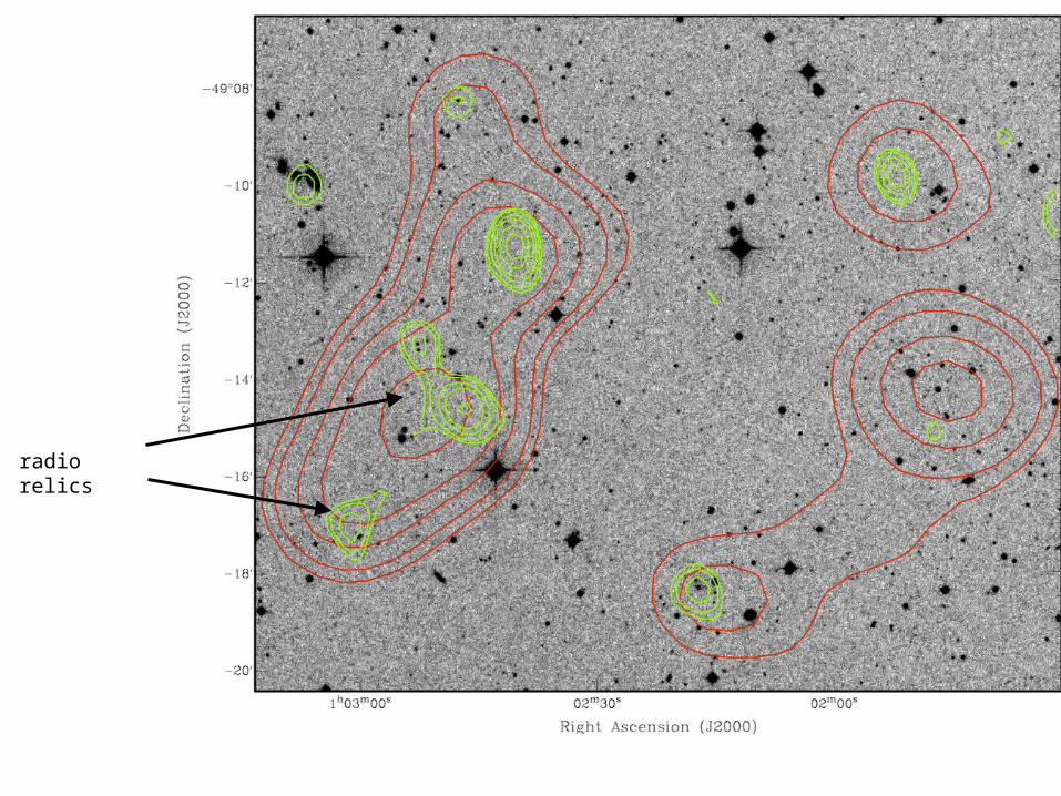
radio relics
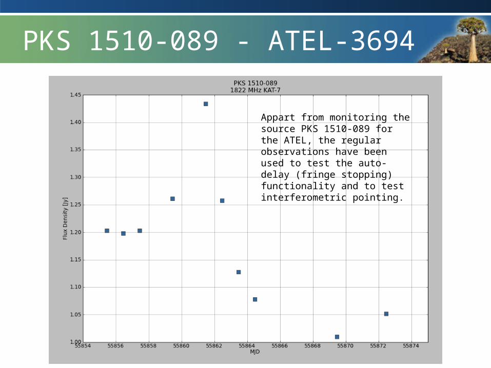
PKS 1510-089 - ATEL-3694
Appart from monitoring the source PKS 1510-089 for the ATEL, the regular observations have been used to test the auto-delay (fringe stopping) functionality and to test interferometric pointing.
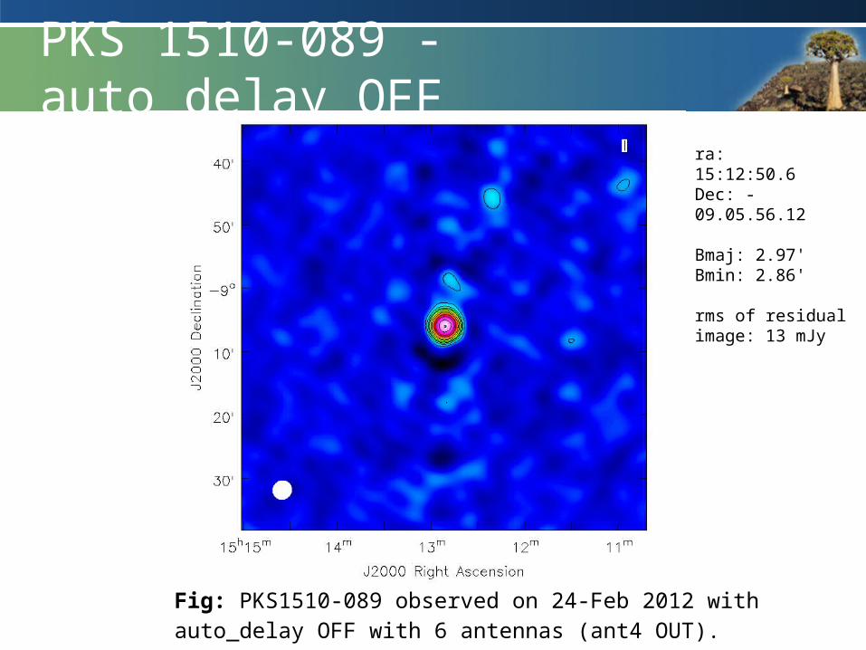
PKS 1510-089 - auto_delay OFFra: 15:12:50.6Dec: -09.05.56.12
Bmaj: 2.97'Bmin: 2.86'
rms of residual image: 13 mJy
Fig: PKS1510-089 observed on 24-Feb 2012 with auto_delay OFF with 6 antennas (ant4 OUT).
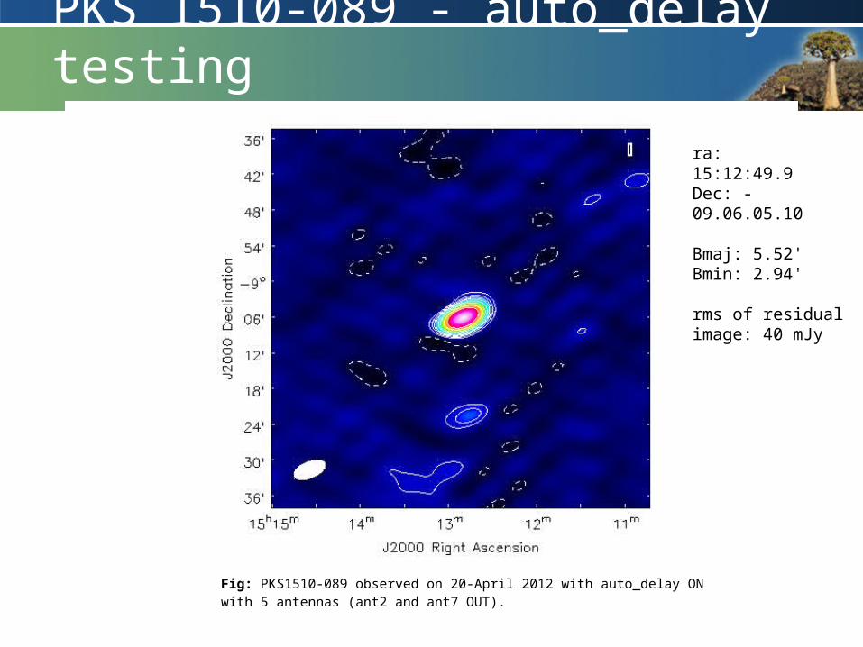
PKS 1510-089 - auto_delay testing
Fig: PKS1510-089 observed on 20-April 2012 with auto_delay ON with 5 antennas (ant2 and ant7 OUT).
ra: 15:12:49.9Dec: -09.06.05.10
Bmaj: 5.52'Bmin: 2.94'
rms of residual image: 40 mJy

Summary
• The industrial commissioning plan is being fine tuned
• The software tools are in place to characterize the system
• The operations and commissioning teams are getting valuable experience in using KAT-7
• We are already doing some continuum/transient science