kapitel 0-1 s210e englisch,englisch · insiden sales fotios tsapkinis tel: +49(0) 2204 40 42 11...
TRANSCRIPT

1
INITIAL OPERATION
OPERATION
MAINTENANCE
ELEKTRICAL SYSTEM
SPARE PARTS
FAULT DIAGNOSTIC
Änderung technischer Daten vorbehalten. Stand: 4/05 Changes of technical datas is possible. Version: April 2005
IMPACTS GmbH IMPACTS GmbH Zöllnerstrasse 7 D-51491 Overath Tel.: +49(0)2204 -4042-0 Fax: +49(0)2204 -4042 22 e-Mail: [email protected] Internet: www.impactsgmbh.de
IMPACTS GmbH Sales, Service and Application Advice Elmar Koster Neusser Strasse 53 D-50181 Bedburg Tel.: +49(0) 151 180 58 454 Fax: +49(0) 2272 90 62 78 E-Mail: [email protected] IMPACTS GmbH Sales,Service and Application Advice Michael Zutter Heider Mühle 12 D-51491 Overath Tel.: +49(0) 151 180 58 456 Fax: +49(0) 2204 40 42 22 E-Mail: [email protected] IMPACTS GmbH Insiden Sales Fotios Tsapkinis Tel: +49(0) 2204 40 42 11 Fax: +49(0) 2204 40 42 22 E-Mail: [email protected] IMPACTS GmbH Sales and Application Advice Werner Geilenkirchen Welscher Heide 14 D-51465 Bensberg Tel: +49 (0) 151 180 58 51 FAX: +49(0) 2204 40 42 22 E.-Mail: [email protected]
TECHNICAL DATA
SAFETY INSTRUCTIOS
GENERAL
TRANSPORTATION

HERE You will find us here
2
NOTIZEN: A4 Ausfahrt Untereschbach,- an der Ampel der Ausfahrt links abbiegen ,- bis zur nächsten Ampel nach ca. 200m(Kreuzung), - dort links einordnen und abbiegen , ca. 300m geradeaus über kleinere Brücke , hinter der an der Brücke gelegenen Tankstelle links einordnen und abbiegen . Nach ca. 20 m sofort wieder links auf den hinter der Tankstelle gelegenen Platz abbiegen.

S210E Operating Manual
Safety Advices
1
Chapter 2
2.0 Explanation of warnings and symbols PAGE: 2
2.1 Organisationel measures PAGE: 4-5
2.2 Personnel selection and qualification PAGE: 5
2.3 Safety precautions applicable to different operating conditions PAGE:
6
2.4 Repair work , maintenance activities, and default repair on the job side PAGE:
7-8
2.5 Definition of the Safety off position PAGE: 9
2.6 Dangerous aspects of the machine PAGE: 9
2.7 Electrical engineering regulations PAGE: 10
2.8 For special attention PAGE: 11

Operating Manual S210E
Safety Instructions
2
2.0 Warnings and symbols
The following denominations and symbols are used in the Operating Instructions to highlight areas of particular importance:
Symbol of operational safety. This symbol will be shown in these Operating Instructions next to all safety precautions that are to be taken in order to ensure prevention to life and injury. Follow always these instructions and take special care in these circumstances. In addition to these instructions, the general safety precautions and the local accident prevention guidelines are also to be followed. Please check, whether there are special regulations for the particular job side.
Information, instructions and restrictions with regards to possible risks to persons or extensive material damages.
Particular details regarding the economical use of the equipment

S210E Operating Manual
Safety Advices
3
Warning against dangerous voltages.
Indications relating to protective devices of electrical equipment.
Indications where consultation with the manufacturer is necessary
Instructions relating to periodical checks
Reference to important instructions contained in the Operating Instructions

Operating Manual S210E
Safety Instructions
4
The Oprerating Instructions are to be kept near the location where the machine is located and must be reachable all the time! In addition to the Operating Instructions general and legal regulations regarding accident prevention and environmental protection must be with and indicated every time.! Such duties may for example relate to the handling of hazardous substances or to the provision and wearing of personal protection equipment as well as compliance with local traffic regulations.. The Operating Instructions must be supplemented by instructions including the duty to supervise and report relating to particular local working pratices, for example work organisation, work procedures and personnel allocation. Personnel entrusted with working with the machine must have read the Operating Instructions before starting the work, in particular the chapter about Safety Instructions.These has to be done before starting any work with the machine.This particularly applies to incidental activities such as setting up the machine, carrying out maintenance work or training staff to work with the machine. From time to time the working practices of the staff are to be checked regarding awareness of safety and hazards. Personnel must tie back long hair and not wear loose clothing or jewellery rings. There is a risk of injury through getting stuck or being drawn into moving machinery.
Use personal protection equipment if necessary or required by regulations! Take notice of allsafety and hazard notices on the machine.
All safety and hazard notices on the machine must be keept complete and readable
2.1 Organisational measures
S210E Operating Manual
Safety Advices
5
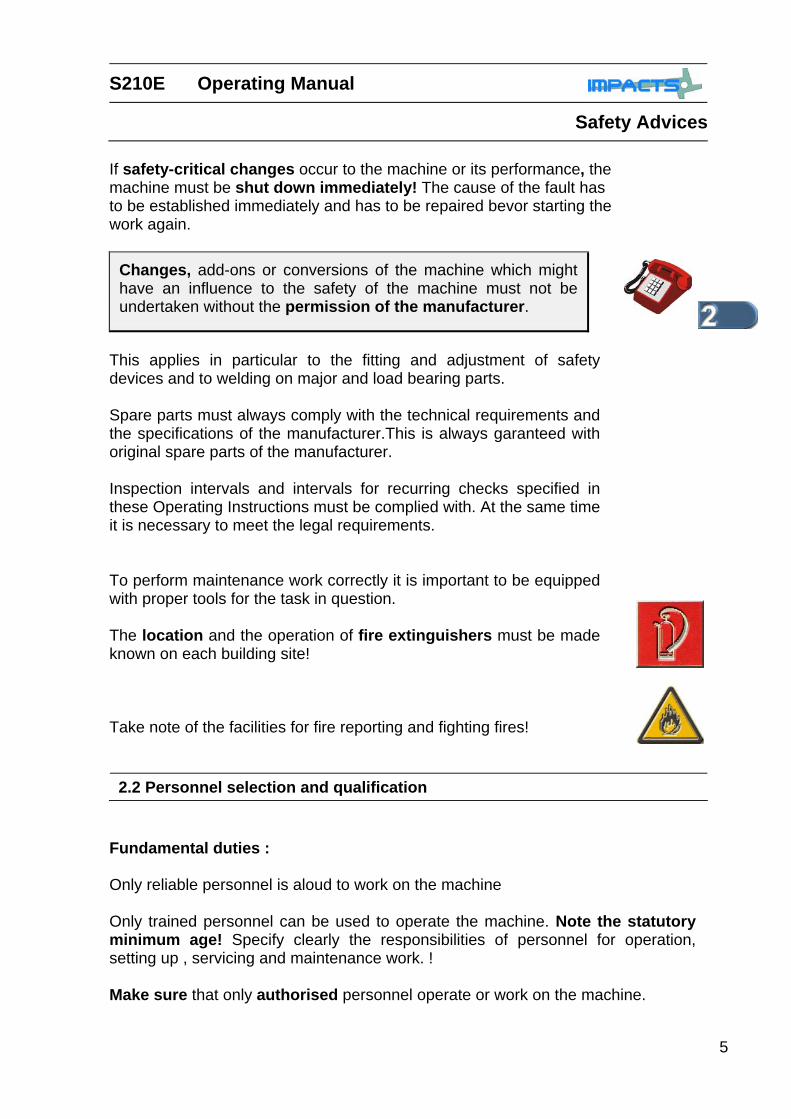
If safety-critical changes occur to the machine or its performance, the machine must be shut down immediately! The cause of the fault has to be established immediately and has to be repaired bevor starting the work again.
Changes, add-ons or conversions of the machine which might have an influence to the safety of the machine must not be undertaken without the permission of the manufacturer.
This applies in particular to the fitting and adjustment of safety devices and to welding on major and load bearing parts. Spare parts must always comply with the technical requirements and the specifications of the manufacturer.This is always garanteed with original spare parts of the manufacturer. Inspection intervals and intervals for recurring checks specified in these Operating Instructions must be complied with. At the same time it is necessary to meet the legal requirements. To perform maintenance work correctly it is important to be equipped with proper tools for the task in question. The location and the operation of fire extinguishers must be made known on each building site! Take note of the facilities for fire reporting and fighting fires! 2.2 Personnel selection and qualification
Fundamental duties : Only reliable personnel is aloud to work on the machine Only trained personnel can be used to operate the machine. Note the statutory minimum age! Specify clearly the responsibilities of personnel for operation, setting up , servicing and maintenance work. ! Make sure that only authorised personnel operate or work on the machine.

Operating Manual S210E
Safety Instructions
6
Select clearly the machine operator. Define his responsibilities also regarding to traffic safety regulations and empower him to decline instructions from third parties which are not complying with the safety requirements. Personnel being trained or made acquainted with the equipment may onlyn be deployed under constant supervision of an experienced person.
Work on the electrical parts of the equipment may only be undertaken by a skilled electrician or by a trained person under the guidance and supervision of a skilled electrician as well as in accordance with the electrical engineering regulations.
2.3 Safety precautions applicable to different operating conditions Avoid any method of working that impairs safety! All precautions have to be taken, that the machine will only be used in a safe and functional status.
Only operate the machine when all safety devices and related safety equipment , e.g. detachable safety devices , emergency stops and suction devices are present and operational!
The machinen has to be checked visually at least once a day for any demage and defects. In the event of operational malfunctions the machine must be shut down immediately andsecured. The fault must be rectified before starting the machine again!
Secure the work area around the machine in public areas
providing a safety distance of at least 2 m around the machine.

S210E Operating Manual
Safety Advices
7
Default must be rectified immediately!
Start up and switch off operations and control devices have to be handle in accordance with the Operating Instructions.
Use only extention cables for extending the main cable that are sized and marked in accordance with the overall power consumption of the machine and the valid VDE and local guidelines..
Before starting the machine make sure that nobody can be endangered when the machines starts running.! Do not switch of or remove the exhaust and ventilation devicews when the machine is running!
Mechanical servicing work : Before starting any servicing work on the machine, put the machine in the Safety off position as described in chapter 2.5 in order to prevent the machine from being switched on accidentally. Please follow any spezial safety instructions in the various chapters on servicing the machine. See chapter 7 Adjustments,servicing and inspection work and inspection intervals specified in these Operating Instructions as well as any information on the replacement on parts and systems of the machine must be undertaken and / or complied with. These activities can only be undertaken by qualified personnel.
All persons in the proximity of the machine must wear safety glasses with lateral protection as well as safety shoes. Ear protection may be required. The operator is obliged to wear close fitting protective clothing.
2.4 Special work within the scope of use of the machine and maintenance activities as well as repairs during operation.
Operating Manual S210E
Safety Instructions
8
Before starting any maintenance or repair work the operator of the machine has to be informed about it.
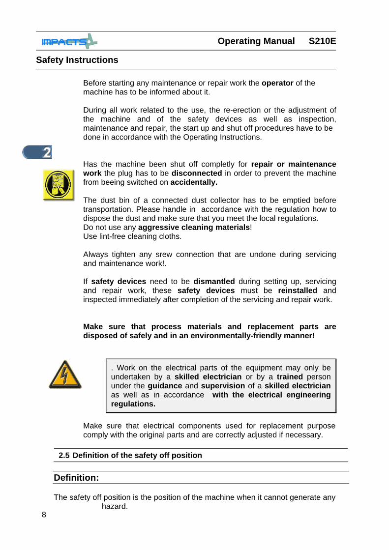
During all work related to the use, the re-erection or the adjustment of the machine and of the safety devices as well as inspection, maintenance and repair, the start up and shut off procedures have to be done in accordance with the Operating Instructions. Has the machine been shut off completly for repair or maintenance work the plug has to be disconnected in order to prevent the machine from beeing switched on accidentally. The dust bin of a connected dust collector has to be emptied before transportation. Please handle in accordance with the regulation how to dispose the dust and make sure that you meet the local regulations. Do not use any aggressive cleaning materials! Use lint-free cleaning cloths. Always tighten any srew connection that are undone during servicing and maintenance work!. If safety devices need to be dismantled during setting up, servicing and repair work, these safety devices must be reinstalled and inspected immediately after completion of the servicing and repair work. Make sure that process materials and replacement parts are disposed of safely and in an environmentally-friendly manner!
Make sure that electrical components used for replacement purpose comply with the original parts and are correctly adjusted if necessary.
2.5 Definition of the safety off position Definition: The safety off position is the position of the machine when it cannot generate any
hazard.
. Work on the electrical parts of the equipment may only be undertaken by a skilled electrician or by a trained person under the guidance and supervision of a skilled electrician as well as in accordance with the electrical engineering regulations.

S210E Operating Manual
Safety Advices
9
Putting the machine in the safety off position means: Switch off the blast machine. Switch off the dust collector. Wait for standstill of all drives.
Pull out main plugs. Secure the machine against accidental start up. 2.6 Particular dangerous aspects of the machine
Every machine, i fit is not used according to the regulations, may be hazardous for operating, setting-up and service personnel.The operating authority is responsible for compliance with the safety regulations during operation and maintenance of safety devices supplied with the machine as well as the provision of appropriate additional safety devices.
Danger of injury ! Abrasive leaves housing with high speed!
Moving parts !
Lift and kant the machine only when it is in Safety off position!
It is not allowed to stay within the working radius of the machine!
Operating Manual S210E
Safety Instructions
10
If work on life parts is necessary, a second person must be deployed who can pull out the plug in an emergency. The working area must be sealed with a red and white safety chain and a danger sign. Use tools that are insulated against voltages. Only start work, once you are familar with the electrical engineering regulations that apply to your area. Only use voltage seekers that comply with the regulations when troubleshooting. From time to time check voltage seekers to ensure that they are operationally efficient.
2.7 Electrical engineering regulations
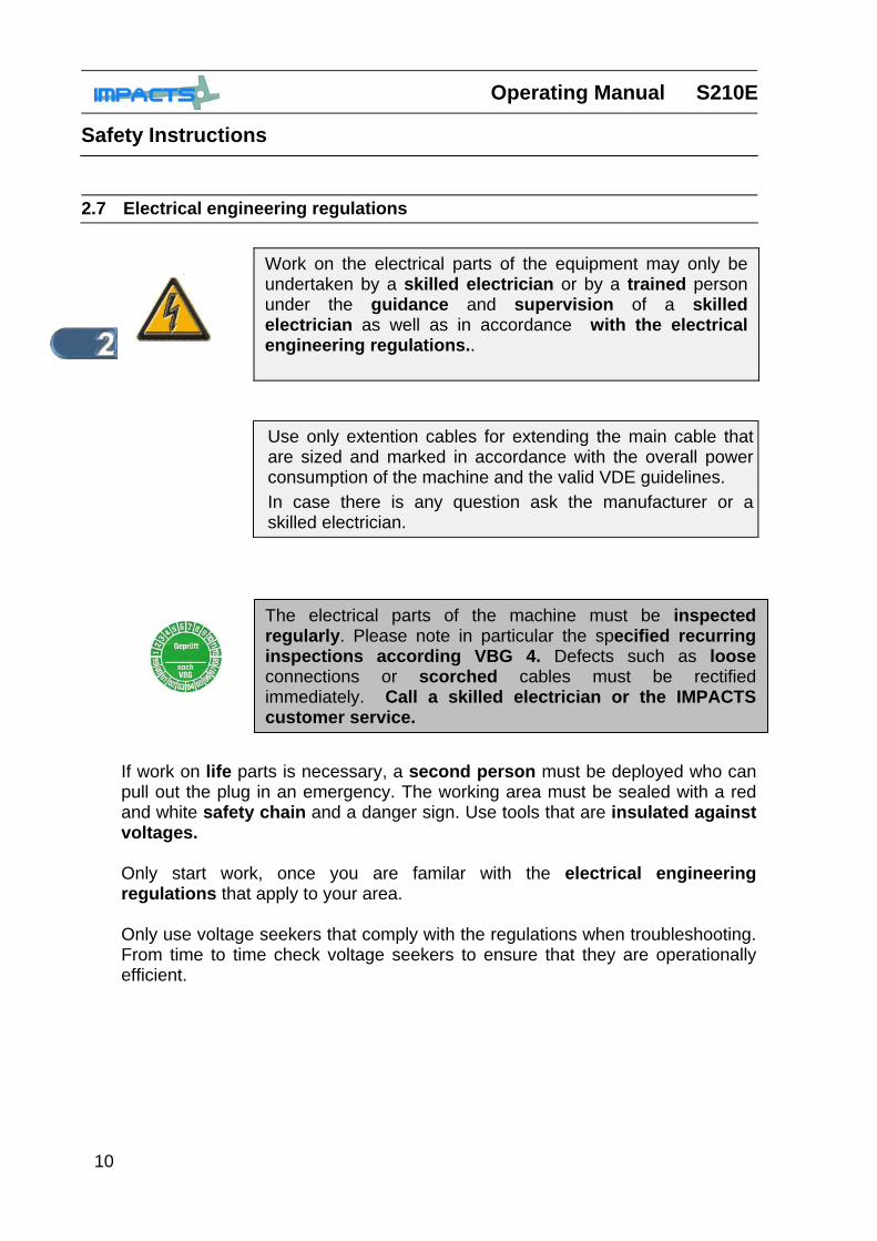
Work on the electrical parts of the equipment may only be undertaken by a skilled electrician or by a trained person under the guidance and supervision of a skilled electrician as well as in accordance with the electrical engineering regulations..
Use only extention cables for extending the main cable that are sized and marked in accordance with the overall power consumption of the machine and the valid VDE guidelines. In case there is any question ask the manufacturer or a skilled electrician.
The electrical parts of the machine must be inspected regularly. Please note in particular the specified recurring inspections according VBG 4. Defects such as loose connections or scorched cables must be rectified immediately. Call a skilled electrician or the IMPACTS customer service.
S210E Operating Manual
Safety Advices
11
2.8 For special attention
Use only proper and default free tools for your work. Damaged tools have to be repaired immediately or to be replaced. Use during your work for your own safety the requitred safety equipment qand safety cloths ( e.g. safety glasses, safety shoes ,safety gloves) Please instruct your operators and the repair personnel about the following points:
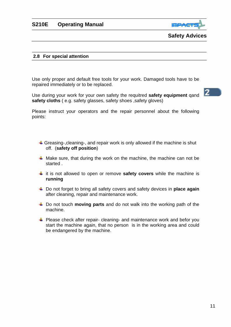
Greasing-,cleaning-, and repair work is only allowed if the machine is shut off. (safety off position)
Make sure, that during the work on the machine, the machine can not be started .
it is not allowed to open or remove safety covers while the machine is running
Do not forget to bring all safety covers and safety devices in place again after cleaning, repair and maintenance work.
Do not touch moving parts and do not walk into the working path of the machine.
Please check after repair- cleaning- and maintenance work and befor you start the machine again, that no person is in the working area and could be endangered by the machine.

Operating Manual S210E
Safety Instructions
12

S210E Operating Instructions
Generals
1
Chapter 3
3.1 Introduction PAGE: 2
3.2 Operating Instructions PAGE: 2
3.3 Connections PAGE: 3
3.4 Care and maintenance PAGE: 3
3.5 Scope of supply PAGE: 3
3.6 Description PAGE: 4-5
3.7 Operating elements PAGE: 5
3.8 Blast wheel PAGE: 6
3.9 Separator PAGE: 7
3.10 Abrasive feed PAGE: 8
3.11 Blast head sealing PAGE: 9
3.12 Suction system PAGE: 10-11
3.13 Abrasive media PAGE: 12
Operating Instructions S210E
Generals
2
3.1 Introduction
IMPACTS GmbH is pleased about your decision, to use the blast machine S210E for the preparation of horizontal surfaces. The machine is a downward blasting machine with a closed abrasive circuit and an incorporated dust extraction. If correctly operated the machine avoids the damage of environment and of the operating personnel. The blast machine S210E is designed to remove surface contaminants, thin coatings, paints and sealants and can be used on different horizontal surfaces like concrete , asphalt and steel.
3.2 Operating Instructions
This hand book has been developed, to help the operators of the machine to operate it in an optimal way, to show how the machine performs and to guarantee an optimal repair and maintenance work.
Because of that, it is mandatory, that all persons, which operate the machine, which do maintenance and repair work to the machine, read this hand book very carefully and understand all the instructions. The machine has been produced fort he use in the country supplied to. All descriptions and comments are according to the legal regulations of the country and formulated in the language of the countrxy or in english language and the PIKTO GRAMS are in occordance with UVV 1.16. If the operators of thre customers can not read the Operating instructions, it is the clear responsibility of the customer, to train the operators in all details.
Before using the machine the personnel must be familiar with all aspects how to operate the machine, with the safety devices and with the measurements and the weight of the machine.
IMPACTS GmbH offer an intensive training for operaters and maintenance personnel to lern how to operate and maintain the machine The first start up of the machine has to be done very carefully. The operator must completly understand the sequence how to start the different functions and must know how the machine works.
S210E Operating Instructions
Generals
3
Special care and regular maintenance of the machine and its parts are imperative for functioning and safety. In order to prevent unnecessary downtimes it is recommended to keep original spare and ware parts on stock as listed in the tool box. A list of contents of the tool box is provided in Chapter 10 to enable the above mentioned work to be carried out quickly.
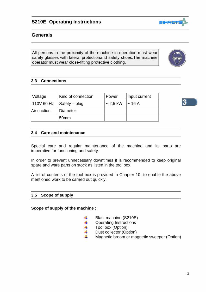
Scope of supply of the machine :
Blast machine (S210E) Operating Instructions Tool box (Option) Dust collector (Option) Magnetic broom or magnetic sweeper (Option)
All persons in the proximity of the machine in operation must wear safety glasses with lateral protectionand safety shoes.The machine operator must wear close-fitting protective clothing.
3.3 Connections
Voltage Kind of connection Power Input current
110V 60 Hz Safety – plug ~ 2,5 kW ~ 16 A
Air suction Diameter
50mm
3.4 Care and maintenance
3.5 Scope of supply
Operating Instructions S210E
Generals
4
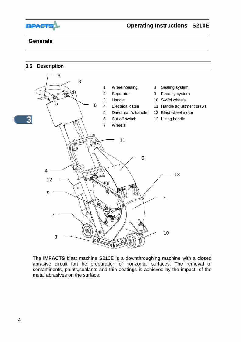
3.6 Description
The IMPACTS blast machine S210E is a downthroughing machine with a closed abrasive circuit fort he preparation of horizontal surfaces. The removal of contaminents, paints,sealants and thin coatings is achieved by the impact of the metal abrasives on the surface.
1 Wheelhousing 8 Sealing system 2 Separator 9 Feeding system 3 Handle 10 Swifel wheels 4 Electrical cable 11 Handle adjustment srews 5 Daed man`s handle 12 Blast wheel motor 6 Cut off switch 13 Lifting handle 7 Wheels
1
2
3
4
5
6
7
8
9
10
11
12 13

S210E Operating Instructions
Generals
5
The wheel blast method is based on a simple principle: after mechanical pre-acceleration the abrasive is thrown onto the surface by the blast wheel. Once the abrasive has impacted on the surface it rebounds into a rebound plenum. The rebound plenum deflects the abrasives into a separator. Here dust and other contaminants are removed from the abrasive so that only abrasive containing a very smal amount of remaining dust is fed back into the abrasive storage hopper for re-use by the blast wheel. For the removal of the dust it is necessary to connect the blast machine with a capable dust collector. -IMPACTS recommends the DC 3003K-. The hight of the blast machine can varied by the adjustable handle.This in connection with the lifting handle on the housing makes it easy to transport the machine. The connection of the machine with the right dust collector gives an enviromental friendly usage of the machine and clean air at the working place.
The dead man`s switch (1), at the handle opens the magnetic valve and switches via the incorporated micro switch (2) the wheel motor ON and OFF.
If the dead man`s switch (1) is released it goes down through a feather mechanism, the motor is cut off and at the same time the magnetic valve is closed and the abrasive feed is stopped In case of an emergency the wheel motor can be stopped through the emergency stopp switch (3)
3.7 Operating elements
2
1
3
Operating Instructions S210E
Generals
6
3.8 The blast wheel
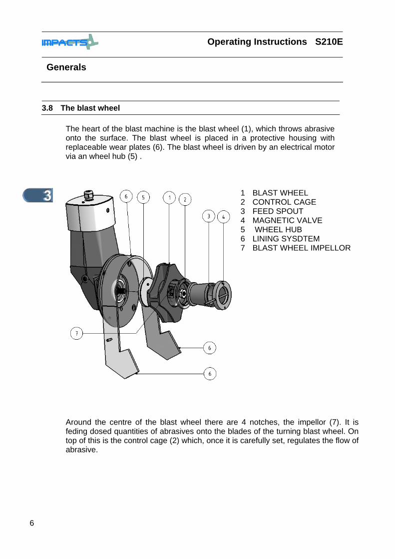
The heart of the blast machine is the blast wheel (1), which throws abrasive onto the surface. The blast wheel is placed in a protective housing with replaceable wear plates (6). The blast wheel is driven by an electrical motor via an wheel hub (5) .
1 BLAST WHEEL 2 CONTROL CAGE 3 FEED SPOUT 4 MAGNETIC VALVE 5 WHEEL HUB 6 LINING SYSDTEM 7 BLAST WHEEL IMPELLOR
Around the centre of the blast wheel there are 4 notches, the impellor (7). It is feding dosed quantities of abrasives onto the blades of the turning blast wheel. On top of this is the control cage (2) which, once it is carefully set, regulates the flow of abrasive.
S210E Operating Instructions
Generals
7
3.9 Separator
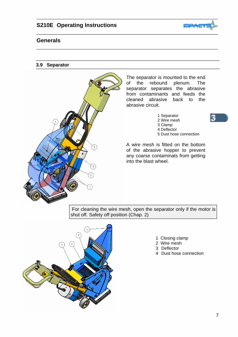
The separator is mounted to the end of the rebound plenum. The separator separates the abrasive from contaminants and feeds the cleaned abrasive back to the abrasive circuit.
1 Separator 2 Wire mesh 3 Clamp 4 Deflector 5 Dust hose connection
A wire mesh is fitted on the bottom of the abrasive hopper to prevent any coarse contaminats from getting into the blast wheel.
For cleaning the wire mesh, open the separator only if the motor is shut off. Safety off position (Chap. 2)
1 Closing clamp 2 Wire mesh 3 Deflector 4 Dust hose connection
Operating Instructions S210E
Generals
8
3.10 Abrasive feed
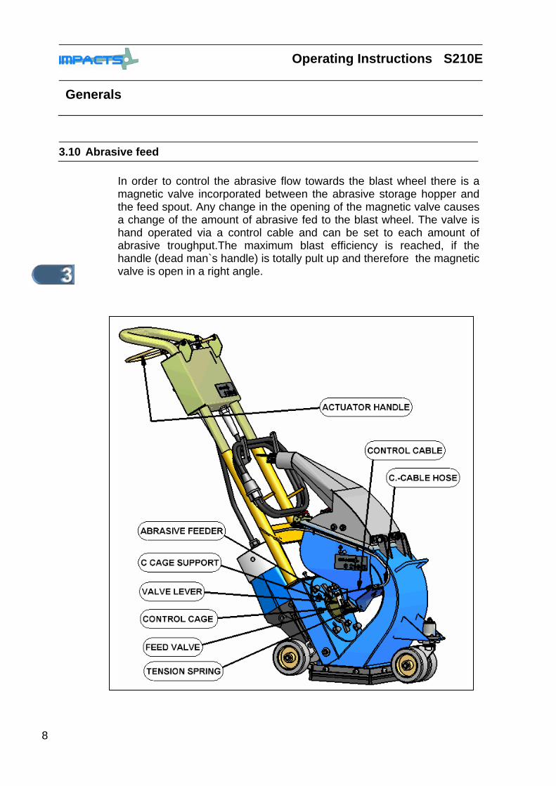
In order to control the abrasive flow towards the blast wheel there is a magnetic valve incorporated between the abrasive storage hopper and the feed spout. Any change in the opening of the magnetic valve causes a change of the amount of abrasive fed to the blast wheel. The valve is hand operated via a control cable and can be set to each amount of abrasive troughput.The maximum blast efficiency is reached, if the handle (dead man`s handle) is totally pult up and therefore the magnetic valve is open in a right angle.
S210E Operating Instructions
Generals
9
3.11 Blast head sealing
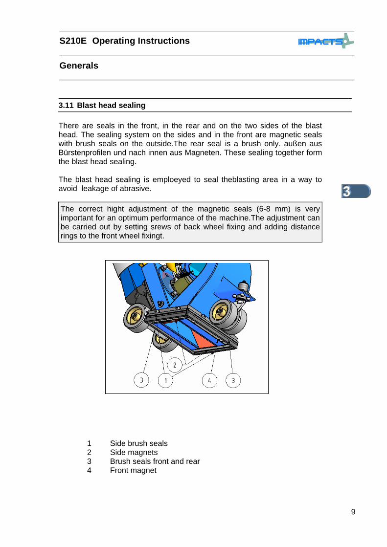
There are seals in the front, in the rear and on the two sides of the blast head. The sealing system on the sides and in the front are magnetic seals with brush seals on the outside.The rear seal is a brush only. außen aus Bürstenprofilen und nach innen aus Magneten. These sealing together form the blast head sealing. The blast head sealing is emploeyed to seal theblasting area in a way to avoid leakage of abrasive.
The correct hight adjustment of the magnetic seals (6-8 mm) is very important for an optimum performance of the machine.The adjustment can be carried out by setting srews of back wheel fixing and adding distance rings to the front wheel fixingt.
1 Side brush seals 2 Side magnets 3 Brush seals front and rear 4 Front magnet
Operating Instructions S210E
Generals
10
3.12 The suction system
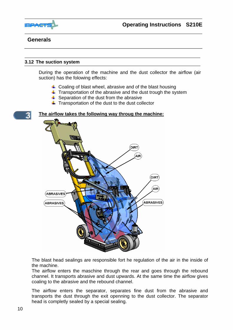
During the operation of the machine and the dust collector the airflow (air suction) has the folowing effects:
Coaling of blast wheel, abrasive and of the blast housing Transportation of the abrasive and the dust trough the system Separation of the dust from the abrasive Transportation of the dust to the dust collector
The airflow takes the following way throug the machine:
The blast head sealings are responsible fort he regulation of the air in the inside of the machine. The airflow enters the maschine through the rear and goes through the rebound channel. It transports abrasive and dust upwards. At the same time the airflow gives coaling to the abrasive and the rebound channel. The airflow enters the separator, separates fine dust from the abrasive and transports the dust through the exit openning to the dust collector. The separator head is completly sealed by a special sealing.
S210E Operating Instructions
Generals
11
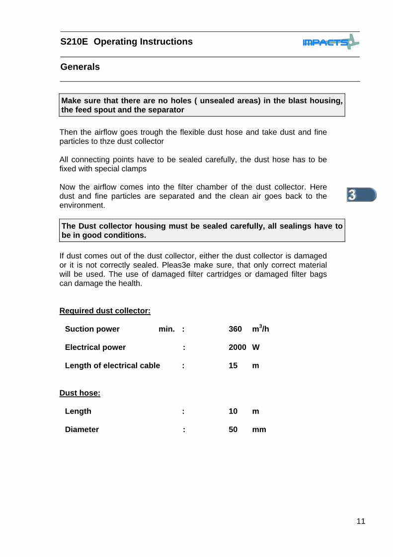
Then the airflow goes trough the flexible dust hose and take dust and fine particles to thze dust collector All connecting points have to be sealed carefully, the dust hose has to be fixed with special clamps Now the airflow comes into the filter chamber of the dust collector. Here dust and fine particles are separated and the clean air goes back to the environment.
The Dust collector housing must be sealed carefully, all sealings have to be in good conditions.
If dust comes out of the dust collector, either the dust collector is damaged or it is not correctly sealed. Pleas3e make sure, that only correct material will be used. The use of damaged filter cartridges or damaged filter bags can damage the health.
Required dust collector: Suction power min. : 360 m3/h Electrical power : 2000 W Length of electrical cable : 15 m
Dust hose: Length : 10 m Diameter : 50 mm
Make sure that there are no holes ( unsealed areas) in the blast housing, the feed spout and the separator

Operating Instructions S210E
Generals
12
3.13 Abrasive media
In order to operate the IMPACTS blast machine S210E you need hardened , round abrasive. The IMPACTS abrasives IMPACTOR S330 and S390 are standard abrasives, which can be used for most of the applications. The machine has been specially designd to use these abrasives.l The IMPACTS abrasive IMPACTOR is a very high quality blast media. It has the right rebound power to use the S210E blast machine very efficient.. The selection of the blast media is very important, if you consider that this is the material which gives the treatment to the surface.
S210E Operating Manual
Transport
1
Chapter 4
4.1 Manual moving of the machine PAGE: 2
4.2 Transport with hoisting equipment PAGE: 3
4.3 Transport of the machine in vehicles PAGE: 4
4.4 Moving the machine during blasting work
PAGE: 4

Operating Manual S210E
Transport
2
4.1 Manual moving of the machine
In order to move the machine on a building site, you have to push the handle down so that the front of the machine will lift and is around 10-20 cm above the floor.
Keep the handle pushed down and move the machine by using the rear wheels.into the new position. Make sure, that you do not draw the lever ( deeds man handle), otherwise you open the magnetic valve and abrasive will dropp on the floor. The transport of the machine has to be done separatly:
• Blast machine S210E • Dust colléctor DC3003G or DC3003K • other material

S210E Operating Manual
Transport
3
4.2 Transport of the machine with hoisting equipment
When transporting the machine with hoisting equipment like a crane or a lift, check the total weight permitted. (Chapter 1.2 dimensions) Please use only appropriate, allowed and qualified hoisting equipment (2) as well as roaps and chains (1). You willm find the weight of the equipment in chapter 1.2 or on the serial plate on the machine. Do not fix any roap or chain (1) to the handle (3), The handle is only fixed with two fixing srews and can not at all been used for transport or to fix roaps or hoisting equipment !
Operating Manual S210E
Transport
4
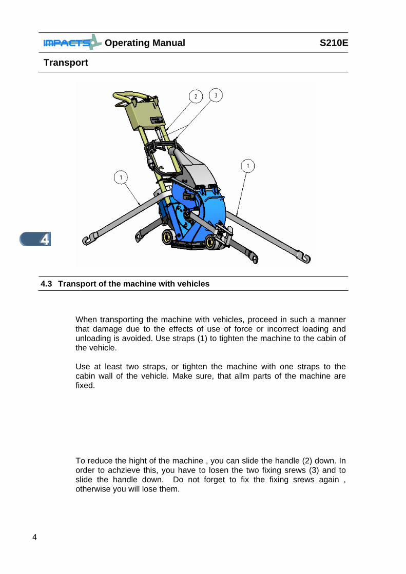
When transporting the machine with vehicles, proceed in such a manner that damage due to the effects of use of force or incorrect loading and unloading is avoided. Use straps (1) to tighten the machine to the cabin of the vehicle. Use at least two straps, or tighten the machine with one straps to the cabin wall of the vehicle. Make sure, that allm parts of the machine are fixed.
To reduce the hight of the machine , you can slide the handle (2) down. In order to achzieve this, you have to losen the two fixing srews (3) and to slide the handle down. Do not forget to fix the fixing srews again , otherwise you will lose them.
4.3 Transport of the machine with vehicles

S210E Operating Manual
Transport
5
4.4 Moving the machine during blasting work
Please look into chapter 5 , START UP

S210E Operating Manual
Start Up
1
Chapter 5
5.1 Preparation for Start up PAGE: 2
5.2 Filling the abrasive hopper PAGE: 3
5.3 Start up PAGE: 4-5

Operating Manual S210E
Start Up
2
5.1 Preparation for start up Move the balst machine and the dust colector to the working site. Check the blast wheel, control cage, feed spoud, all liners and the separator for damages and wear. Worn and damaged parts have to be changed before starting the work. Before switching on make sure that all existing protective housings are mounted and that a sufficient dust collector is connected correctly.
All persons in the proximity of the machine must wear safety glases with lateral protection as well as safety shoes. The operator of the machine is obliged to wear close-fitting protective clothing
Handle all plugs, cables, hoses and operating devices with care . Avoid any contact with live wires. Works on the electrical system must only be carried out by a qualified electrician. Check the surface to be treated for loose parts( stones,srews, etc).The surface must be sweept if necessary. Make sure that the machine can travel over all inequalities on the surface. Smal inequalities like welding seams or floor joints are no barriers for the machine.
Before start up the operation pesonnel must be familiar with the safety regulations given in this operating instructions.
Check the height adjustment of the (approx. 6 .- 8 mm) of the blast machine. Chapter 7 of the operating instructions. Check the main electrical cable and the dust hose for damages. Exchange or repair all damaged parts before starting the machine. Connect the blast machine and the dust collector unit with the dust hose. Use hose clamps at the connections. Connect the supply cable of the dust collector with the site supply. Connect the supply cable of the blast machine with the site supply. Make sure, that the right connection (230 V, 50 Hz, 16A) is available.
S210E Operating Manual
Start Up
3
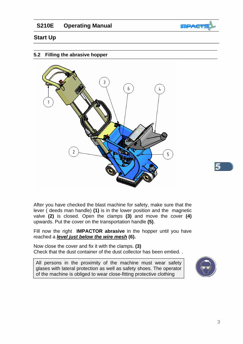
After you have checked the blast machine for safety, make sure that the lever ( deeds man handle) (1) is in the lower position and the magnetic valve (2) is closed. Open the clamps (3) and move the cover (4) upwards. Put the cover on the transportation handle (5). Fill now the right IMPACTOR abrasive in the hopper until you have reached a level just below the wire mesh (6). Now close the cover and fix it with the clamps. (3) Check that the dust container of the dust collector has been emtied. .
5.2 Filling the abrasive hopper
All persons in the proximity of the machine must wear safety glases with lateral protection as well as safety shoes. The operator of the machine is obliged to wear close-fitting protective clothing

Operating Manual S210E
Start Up
4
5.2 Start up The working and moving direction of the blast machine is in the direction of the arrow (V) shown on the picture. The blast machine and the dust collector will be started in the following sequence:
1) Switch on the dust collector. 2) After the dust collector is running start up the balst machine as
described below.
3) Make sure that the emergency switch (1) is in the upper position and
not pushed down. 4) Push the machine by using the handle (2) slowly in the direction of the
arrow (S) forward (V) and at the same time pull the lever (3) slowly up as much as you can. This action starts th wheelmotor and at the same time the magnetic valve opens and abrasive flows into the blast wheel.
5) Continue to push the machine slowly in direction of the arrow (V) and watch carfully the blasted area. If necessary change the moving speed to achieve the blasting patent you requirer.
S210E Operating Manual
Start Up
5
Do not push the machine down or move it up on the handle (2) during the blast pro cleaning process
When blast cleaning concrete or asphalt the magnetic valve may only be opened when the blast machineis travelling!! If the machine does not move and the valve is open, deep holes may be blasted into the surface within seconds. Alter the travel direction (V) only after having closed the magnetic valve. The dust bin of the dust collector must be emptied regularly. Comply with the local waste treatment regulations considering the removed material.

Operating Manual S210E
Start Up
6

S210E Operating Manual
Operation
1
Chapter 6
6.1 Daily operation PAGE: 2 6.2 Information about travelling speed
and abrasive feeding PAGE: 3-4
6.3 Switching –off the machine PAGE: 5 6.4 What to do if a fault occurs PAGE: 6 6.5 Restarting after a fault PAGE: 7 6.6 Measures before and after a long
standstill PAGE: 7
NOTES 8
Operating Manual S210E
Operation
2
6.1 Daily operation
The operating manual has to be always with the machine at the working site! Use only educated and trained personnel Personal ! Take note of the legal minimum age. Clearly define the responsibility of the personnel for operating, repair and maintenance. Make sure that only those people work on the machine who have been empowered to do so.
Regular inspections are important in order to avoid downtimes ofb your blast machine. Chapter 7 maintenance
For daily operation of the Blast machine S210E please consider the following points: Check daily before starting the operation whether all machine parts are assembled safely and correctly . Before switching on the machine,it must be checked, that all safety covers are in the right position and that the dust collector is connected correctly. IMPACTS recommends hartly , to use only such a dust collector which has the right suction power and gives an optimalm dust separation. Treat all plugs, cables, hoses, and operating devices with special care. Avoid any contact with live wires. Check the surface to be treated for loose parts (Stones,srews, etc) The surface must be swept if necessary. Remove any obsticles from the surface in order to avoid damage to the machine sealing
Using the dust collector make sure to comply with the health and safety regulations and the local waste treatment regulations considering the removed material .
For start up look into Chapter 5.2 of this operating manual
S210E Operating Manual
Operation
3
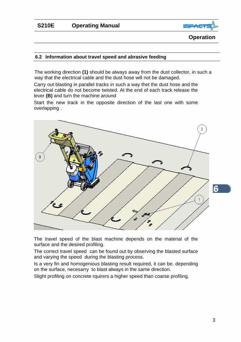
6.2 Information about travel speed and abrasive feeding The working direction (1) should be always away from the dust collector, in such a way that the electrical cable and the dust hose will not be damaged. Carry out blasting in parallel tracks in such a way thet the dust hose and the electrical cable do not become twisted. At the end of each track release the lever (B) and turn the machine around Start the new track in the opposite direction of the last one with some overlapping .
The travel speed of the blast machine depends on the material of the surface and the desired profiling. The correct travel speed can be found out by observing the blasted surface and varying the speed during the blasting process. Is a very fin and homogenious blasting result required, it can be, depending on the surface, necesarry to blast always in the same direction. Slight profiling on concrete rquirers a higher speed than coarse profiling.
Operating Manual S210E
Operation
4
Blasting on steel requires a very low travel speed of the machine.. The selected abrasive will as well influence the profiling of the surface , The selection of a fine or coarse abrasive in relation to the surface to be blasted can give an advantage in connection with the profiling as well as for the blasting capacity. The selection of the right travel speed of the blast machine is important fort he blasting result. If the surface shows different charateristics (hardness or different thickness of the overlayment), a uniform blast result can be achieved by varying the travel speed of the blast machine during blasting. Make sure that no vehicles , such as forklift trucks and othet equipment run over the electrical cable and the dust hose.
S210E Operating Manual
Operation
5
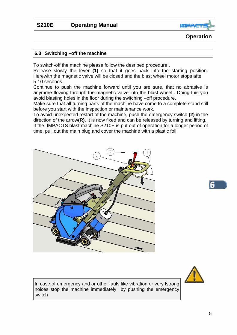
To switch-off the machine please follow the desribed procedure:. Release slowly the lever (1) so that it goes back into the starting position. Herewith the magnetic valve will be closed and the blast wheel motor stops afte 5-10 seconds. Continue to push the machine forward until you are sure, that no abrasive is anymore flowing through the magnetic valve into the blast wheel . Doing this you avoid blasting holes in the floor during the switching –off procedure. Make sure that all turning parts of the machine have come to a complete stand still before you start with the inspection or maintenance work. To avoid unexpected restart of the machine, push the emergency switch (2) in the direction of the arrow(R), It is now fixed and can be released by turning and lifting. If the IMPACTS blast machine S210E is put out of operation for a longer period of time, pull out the main plug and cover the machine with a plastic foil.
6.3 Switching –off the machine
In case of emergency and or other fauls like vibration or very lstrong noices stop the machine immediately by pushing the emergency switch

Operating Manual S210E
Operation
6
6.4 What to do if a fault occurs
In a case of emergency you can stop the machine immediately by pushing the emergency switch . To release the emergency switch,turn the red button and move it upwards .
For repair work bring the machine in the safety-off positon (Chapter 2 )
Make sure that all turning machine parts have come to a standstill before any inspection or maintenance works are started. ( safety off position Chapter 2)
Irrespective of the following information in Chapter 7, the local safety regulations are valid in any case fort he operation of the machine.
S210E Operating Manual
Operation
7
6.5 Restarting after a fault After a fault make sure that you find the reason of the fault before you restart the machine. Leave the emergency switch pushed down and bring the machine in the safety-off position before you start to find out the fault. If you do not find the fault or if you are unsure about the rfeason forb the fault, please contact your IMPACTS contact person and ask for help. Please consider in special the regulations in VBG 4 and VDE-0701. These regulations describe the necessarry considerations and actions after repairing and changing electrical Equipment. For start up the machine see chapter 5 6.6 Measures before and after long stand stills
Before a long standstill period
In case a long standstill of the IMPACTS blast machine S210E is planed, please consider the following points:
1) Remove all abrasive out of the machine 2) Remove all abrasive from the magnetic seals 3) Clean the machine carfully 4) Storage the machine in a dry area. 5) Preserve bright parts of themachine with oil or greace 6) Cover the machine with a plastic foil.
After a long standstill
Look into Chapter 5 Initial operation

Operating Manual S210E
Operation
8
Notes
Date

S210E Operating Manual
Maintenance
1
Chapter 7 Maintenance 7.1 Recommendations PAGE: 2 7.2 Maintenance and inspection list PAGE: 3 7.3 Repairing PAGE: 4 7.4 The blast pattern PAGE: 5 7.5 Setting the magnetic seals PAGE: 6 7.6 Chance of the blast wheel PAGE: 7-8 7.7 Changing the liners PAGE: 9-10 7.8 Maintenance intervalls PAGE: 11 7.9 General maintenance PAGE: 12 7.10 Recommended spare parts list PAGE: 12
Operating Manual S210E
Maintenance
2
7.1 Recommendations
Prior to any repair work on the machine and ist drives, securen the machine against unintentional switching on. Putt he machine to ist safety off position .Chapter 2
Failures due to inadequate or incorrect maintenance may generate very high repair costs and long standstill periods of the machine. Regular maintenance is therefore imperative. Operational safety and service life of the machine depend, among other things, on proper maintenance. The following table shows recommendations about time, inspection and maintenance for thze normal use of the machine. The time indications are based on uninterrupted operation. When the indicated number of working hours is not achieved during the corresponding period, the period can be extended. However a full overhaul must be carried out at least once a year. Due to the different working conditions it cannot be foreseenhow frequently inspections for wear checkings, inspection, maintenance and repair work ought to be carried out. Prepare a suitable inspection shedule considering your own working conditions. Our specialists will be happy to assist you with more advise.
The subsupplier`s operating and maintenance instructions shouls be also followed during service and maintenance. This applies especially to the instructions for electric components
S210E Operating Manual
Maintenance
3
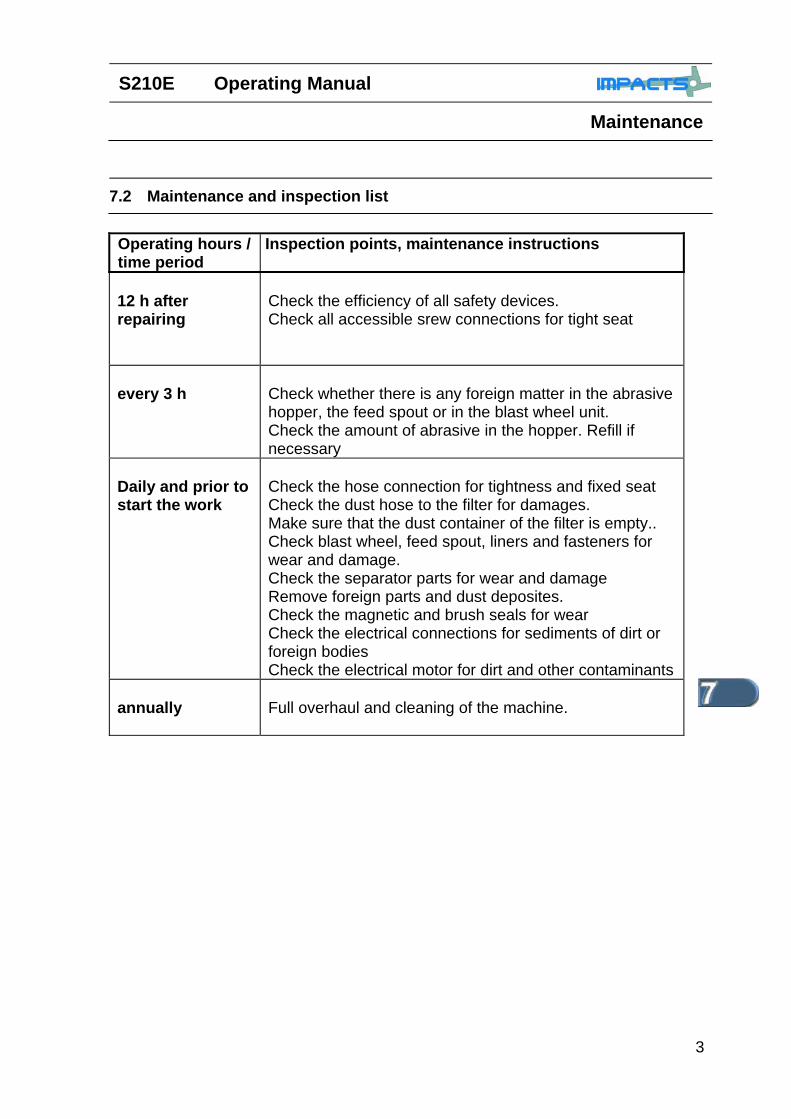
7.2 Maintenance and inspection list Operating hours / time period
Inspection points, maintenance instructions
12 h after repairing
Check the efficiency of all safety devices. Check all accessible srew connections for tight seat
every 3 h
Check whether there is any foreign matter in the abrasive hopper, the feed spout or in the blast wheel unit. Check the amount of abrasive in the hopper. Refill if necessary
Daily and prior to start the work
Check the hose connection for tightness and fixed seat Check the dust hose to the filter for damages. Make sure that the dust container of the filter is empty.. Check blast wheel, feed spout, liners and fasteners for wear and damage. Check the separator parts for wear and damage Remove foreign parts and dust deposites. Check the magnetic and brush seals for wear Check the electrical connections for sediments of dirt or foreign bodies Check the electrical motor for dirt and other contaminants
annually
Full overhaul and cleaning of the machine.
Operating Manual S210E
Maintenance
4
7.3 Repairing
As already mentioned in the chapter initial operation we recommend to execute the first repair works on the machine with the help of IMPACTS-personnel. With this your maintenance personnel gets the opportunity to be trained intensely.
Only those repair works are described which occur within the context of maintenance or which are required to replace wear parts. If you replace parts yourself for specific reasons , the following instructions and work sequence have to be observed. You should stock all spare or wear parts that cannot be supplied quickly. As a rule, production standstill periods are more expensive than the cost for the corresponding spare part. Srews that have been removed must be replaced with those of the same quality ( strength, material) and design.
Prior to any repair work on the machine and ist drives, secure the machine against unintentional switching-on. Pull the main plugs in order to do this. Chapter 2 safety-off position
S210E Operating Manual
Maintenance
5
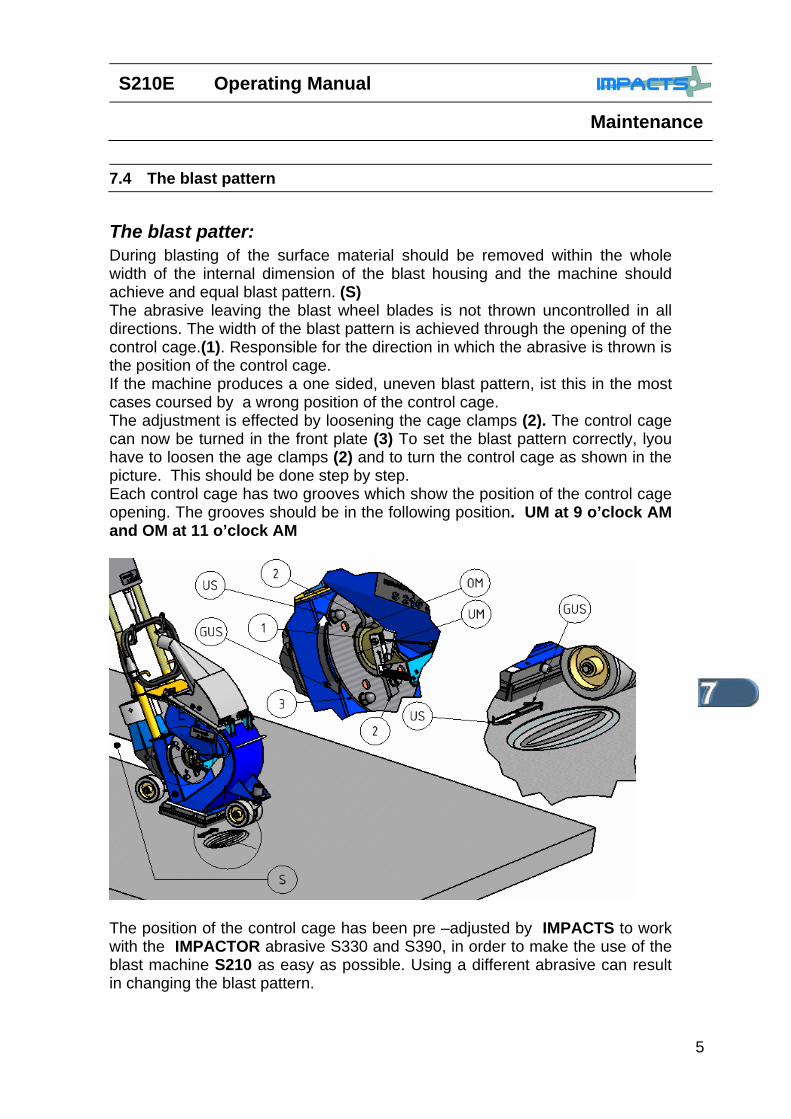
The blast patter: During blasting of the surface material should be removed within the whole width of the internal dimension of the blast housing and the machine should achieve and equal blast pattern. (S) The abrasive leaving the blast wheel blades is not thrown uncontrolled in all directions. The width of the blast pattern is achieved through the opening of the control cage.(1). Responsible for the direction in which the abrasive is thrown is the position of the control cage. If the machine produces a one sided, uneven blast pattern, ist this in the most cases coursed by a wrong position of the control cage. The adjustment is effected by loosening the cage clamps (2). The control cage can now be turned in the front plate (3) To set the blast pattern correctly, lyou have to loosen the age clamps (2) and to turn the control cage as shown in the picture. This should be done step by step. Each control cage has two grooves which show the position of the control cage opening. The grooves should be in the following position. UM at 9 o’clock AM and OM at 11 o’clock AM
The position of the control cage has been pre –adjusted by IMPACTS to work with the IMPACTOR abrasive S330 and S390, in order to make the use of the blast machine S210 as easy as possible. Using a different abrasive can result in changing the blast pattern.
7.4 The blast pattern
Operating Manual S210E
Maintenance
6
7.5 Magnetic seals
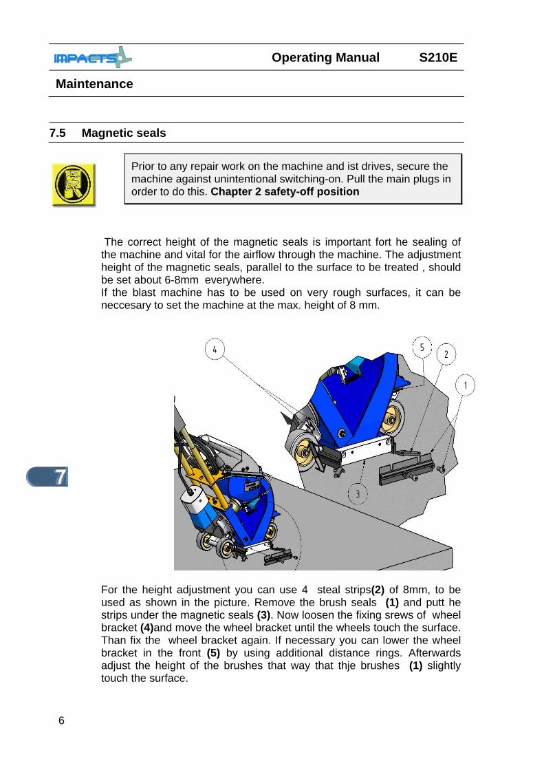
The correct height of the magnetic seals is important fort he sealing of the machine and vital for the airflow through the machine. The adjustment height of the magnetic seals, parallel to the surface to be treated , should be set about 6-8mm everywhere. If the blast machine has to be used on very rough surfaces, it can be neccesary to set the machine at the max. height of 8 mm.
For the height adjustment you can use 4 steal strips(2) of 8mm, to be used as shown in the picture. Remove the brush seals (1) and putt he strips under the magnetic seals (3). Now loosen the fixing srews of wheel bracket (4)and move the wheel bracket until the wheels touch the surface. Than fix the wheel bracket again. If necessary you can lower the wheel bracket in the front (5) by using additional distance rings. Afterwards adjust the height of the brushes that way that thje brushes (1) slightly touch the surface.
Prior to any repair work on the machine and ist drives, secure the machine against unintentional switching-on. Pull the main plugs in order to do this. Chapter 2 safety-off position
S210E Operating Manual
Maintenance
7
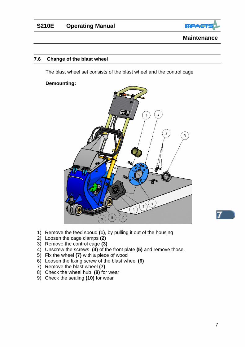
The blast wheel set consists of the blast wheel and the control cage Demounting:
1) Remove the feed spoud (1), by pulling it out of the housing 2) Loosen the cage clamps (2) 3) Remove the control cage (3) 4) Unscrew the screws (4) of the front plate (5) and remove those. 5) Fix the wheel (7) with a piece of wood 6) Loosen the fixing screw of the blast wheel (6) 7) Remove the blast wheel (7) 8) Check the wheel hub (8) for wear 9) Check the sealing (10) for wear
7.6 Change of the blast wheel
Operating Manual S210E
Maintenance
8
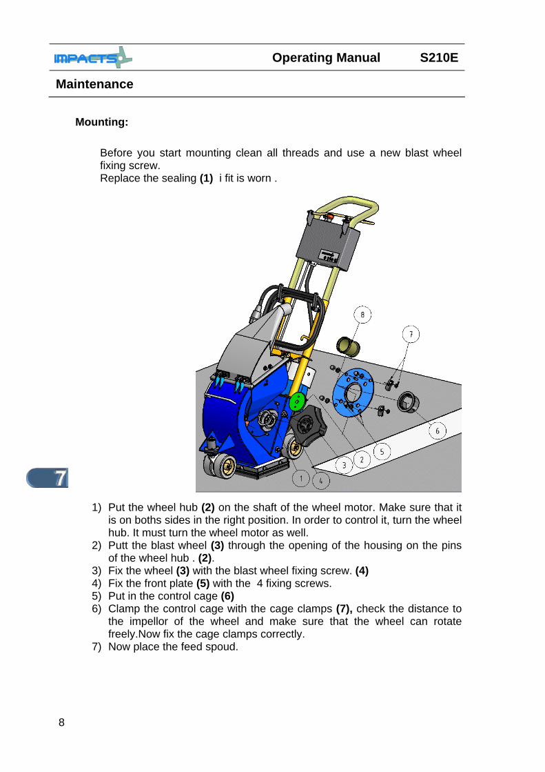
Mounting:
Before you start mounting clean all threads and use a new blast wheel fixing screw. Replace the sealing (1) i fit is worn .
1) Put the wheel hub (2) on the shaft of the wheel motor. Make sure that it is on boths sides in the right position. In order to control it, turn the wheel hub. It must turn the wheel motor as well.
2) Putt the blast wheel (3) through the opening of the housing on the pins of the wheel hub . (2).
3) Fix the wheel (3) with the blast wheel fixing screw. (4) 4) Fix the front plate (5) with the 4 fixing screws. 5) Put in the control cage (6) 6) Clamp the control cage with the cage clamps (7), check the distance to
the impellor of the wheel and make sure that the wheel can rotate freely.Now fix the cage clamps correctly.
7) Now place the feed spoud.

S210E Operating Manual
Maintenance
9
7.7 Changing the liners
Demounting: The removing of the liners is only possible if the blast wheel is
removed as well. Before starting to remove the liners, remove the blast wheel and the wheel hub as described in Chapter 7 .
1) Loosen the fastening screw of the left hand (3) and right hand (4) liner, turn the liners towards the inside ofb the blast housing and take them out at the bottom of the housing.
2) Loosen the counter screw (2) of the pressure screw of the top liner
(5) and turn it completly up.
3) Loosen the pressure screw (2) of the top liner (5) to the end and turn it back til you can remove it. Now put a smal nail through the threat opening and hit it down onto the top liner (5) til it slides downwards. Turn the top liner around the motor shaft and take it out through the bottom of the housing.
4) Take the top liner out trough the bottom opening of the housing.

Operating Manual S210E
Maintenance
10
Mounting: Prior to mounting new liners you should check the wheelhousing and specially the corners for wear.
1) Put the pressure screw (1) fort the top liner in place. 2) Move the top liner (2) through the opening of the wheel housing and turn
it around the motorshaft (6) into the upper part of the housingl. 3) Place the side liners (3 u.4) that way in the housing, that the bolts can
be pushed through the holes in the side of the housing. 4) Put the screws (5) on the bolts and tighten them slightly. 5) Place the side liners (3 u.4) inside the housing in a way that the liner
sticks out approx. 2 mm at the bottom of the housing. Fasten the side liners now with the screws.
6) Now fix the pressure screw (1) that way, that the edges of the top liner sitting on the the upper edges of the side liners..
7) Now mount the remaining components (A), as described in Chapter 7.6, mounting of the blast wheel
8) Set the control cage as described in Chapter 7.6
S210E Operating Manual
Maintenance
11
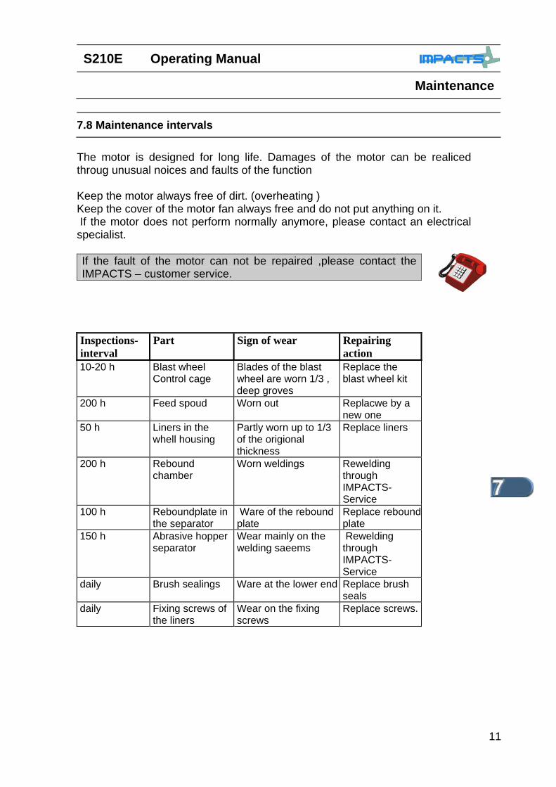
7.8 Maintenance intervals The motor is designed for long life. Damages of the motor can be realiced throug unusual noices and faults of the function Keep the motor always free of dirt. (overheating ) Keep the cover of the motor fan always free and do not put anything on it. If the motor does not perform normally anymore, please contact an electrical specialist. If the fault of the motor can not be repaired ,please contact the IMPACTS – customer service.
Inspections-interval
Part Sign of wear Repairing action
10-20 h Blast wheel Control cage
Blades of the blast wheel are worn 1/3 , deep groves
Replace the blast wheel kit
200 h Feed spoud Worn out Replacwe by a new one
50 h Liners in the whell housing
Partly worn up to 1/3 of the origional thickness
Replace liners
200 h Rebound chamber
Worn weldings Rewelding through IMPACTS-Service
100 h Reboundplate in the separator
Ware of the rebound plate
Replace rebound plate
150 h Abrasive hopper separator
Wear mainly on the welding saeems
Rewelding through IMPACTS-Service
daily Brush sealings Ware at the lower end Replace brush seals
daily Fixing screws of the liners
Wear on the fixing screws
Replace screws.
Operating Manual S210E
Maintenance
12
7.9 Other maintenance
Watch the wear of the brush seals and change them latest, when their is no sufficient sealing anymore. Doing that you stop dust coming to the environment. This saves additional cost From time to time you should put oil on the dead men handle and other moving parts.
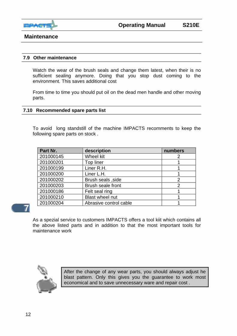
7.10 Recommended spare parts list To avoid long standstill of the machine IMPACTS recomments to keep the following spare parts on stock .
Part Nr. description numbers 201000145 Wheel kit 2 201000201 Top liner 1 201000199 Liner R.H. 1 201000200 Liner L.H. 1 201000202 Brush seals ,side 2 201000203 Brush seale front 2 201000186 Felt seal ring 1 201000210 Blast wheel nut 1 201000204 Abrasive control cable 1
As a spezial service to customers IMPACTS offers a tool kiit which contains all the above listed parts and in addition to that the most important tools for maintenance work
After the change of any wear parts, you should always adjust he blast pattern. Only this gives you the guarantee to work most economical and to save unnecessary ware and repair cost .

S210E Bedienungsanleitung/Operating Manual
Elektrik/Electrics
1
Chapter 8
8.1 Hint s for the Electrics PAGE: 2
8.1 Circuit Diagramm PAGE: 3
Bedienungsanleitung/Operating Manual S210E
Elektrik/Electrics
2
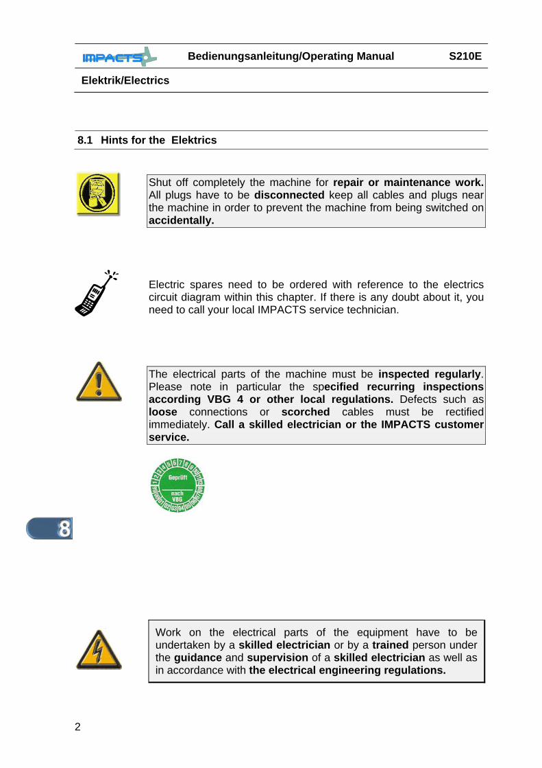
8.1 Hints for the Elektrics
Shut off completely the machine for repair or maintenance work. All plugs have to be disconnected keep all cables and plugs near the machine in order to prevent the machine from being switched on accidentally.
Electric spares need to be ordered with reference to the electrics circuit diagram within this chapter. If there is any doubt about it, you need to call your local IMPACTS service technician.
The electrical parts of the machine must be inspected regularly. Please note in particular the specified recurring inspections according VBG 4 or other local regulations. Defects such as loose connections or scorched cables must be rectified immediately. Call a skilled electrician or the IMPACTS customer service.
Work on the electrical parts of the equipment have to be undertaken by a skilled electrician or by a trained person under the guidance and supervision of a skilled electrician as well as in accordance with the electrical engineering regulations.

S210E Bedienungsanleitung/Operating Manual
Elektrik/Electrics
3
8.2 Circuit Diagram

Bedienungsanleitung/Operating Manual S210E
Elektrik/Electrics
4
NOTES DATE

S210E Bedienungsanleitung/Operating Manual
Diagnosis
1
Chapter 9
9.1 Diagnosis of failures PAGE: 2-3
9.2 Diagnosis of electrical failures PAGE: 4
Bedienungsanleitung/Operation Manual S210E
Diagnosis
2
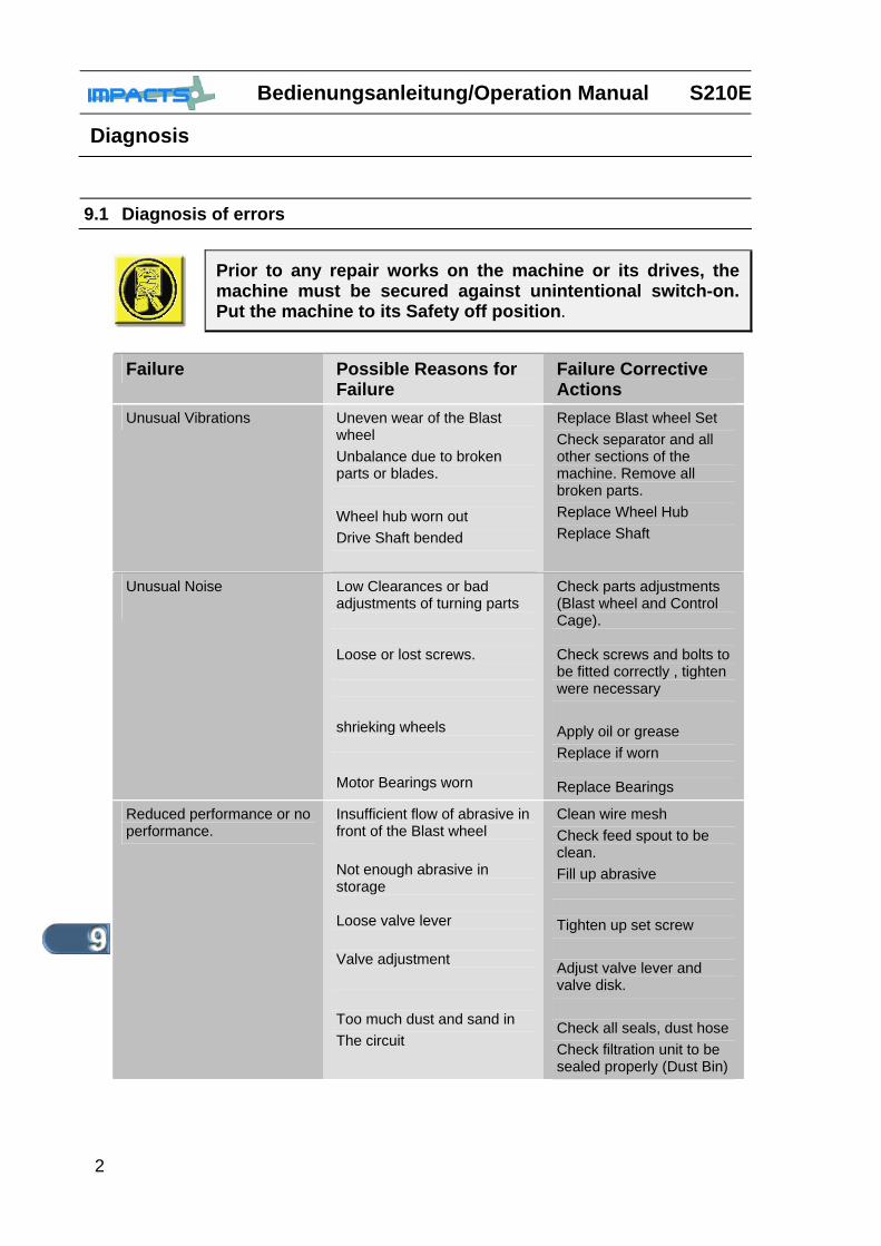
9.1 Diagnosis of errors
Prior to any repair works on the machine or its drives, the machine must be secured against unintentional switch-on. Put the machine to its Safety off position.
Failure Possible Reasons for
Failure Failure Corrective Actions
Unusual Vibrations Uneven wear of the Blast wheel Unbalance due to broken parts or blades. Wheel hub worn out Drive Shaft bended
Replace Blast wheel Set Check separator and all other sections of the machine. Remove all broken parts. Replace Wheel Hub Replace Shaft
Unusual Noise
Low Clearances or bad adjustments of turning parts Loose or lost screws. shrieking wheels Motor Bearings worn
Check parts adjustments (Blast wheel and Control Cage). Check screws and bolts to be fitted correctly , tighten were necessary Apply oil or grease Replace if worn Replace Bearings
Reduced performance or no performance.
Insufficient flow of abrasive in front of the Blast wheel Not enough abrasive in storage Loose valve lever Valve adjustment Too much dust and sand in The circuit
Clean wire mesh Check feed spout to be clean. Fill up abrasive Tighten up set screw Adjust valve lever and valve disk. Check all seals, dust hose Check filtration unit to be sealed properly (Dust Bin)
S210E Bedienungsanleitung/Operating Manual
Diagnosis
3
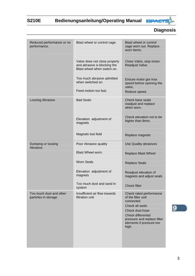
Reduced performance or no performance.
Blast wheel or control cage. Valve does not close properly and abrasive is blocking the Blast wheel when switch on. Too much abrasive admitted when switched on. Feed motion too fast.
Blast wheel or control cage worn out. Replace worn items. Close Valve, stop motor. Readjust Valve. Ensure motor got max speed before opening the valve, Reduce speed.
Loosing Abrasive. Bad Seals Elevation adjustment of magnets Magnets lost field
Check base seals readjust and replace when worn. Check elevation not to be higher than 8mm. Replace magnets
Dumping or loosing Abrasive
Poor Abrasive quality Blast Wheel worn. Worn Seals Elevation adjustment of magnets Too much dust and sand in system
Use Quality abrasives Replace Blast Wheel Replace Seals Readjust elevation of magnets and adjust seals Check filter
Too much dust and other particles in storage
Insufficient air flow towards filtration unit
Check rated performance of the filter unit connected. Check all seals Check dust hose Check differential pressure and replace filter elements if pressure too high.

Bedienungsanleitung/Operation Manual S210E
Diagnosis
4
9.2 Diagnosis of electric errors
Prior to any repair works on the machine or its drives the machine must be secured against unintentional switching-on. Put the machine to its Safety off position.
Work on electrical equipment or operating materials may only be undertaken by a skilled electrician or by trained persons under the guidance and supervision of a skilled electrician as well as in accordance with the electrical engineering regulations.
Failure Possible Reasons for Failure
Failure Corrective Actions
Motor does not start up
Missing Phase Faulty Switch or relays Emergency Stop
Check power supply Diagnosis and replacement by electrician Unlock Emergency Stop Bottom
Motor stops during operation
current too high power supply circuit breaker disengaged Motor is damaged
Disconnect plug Reset Circuit breaker or replace fuse. Adjust max. abrasive feeding. (Needs Amp meter) Check Motor