kapco internship report
DESCRIPTION
KAPCO field study of six weeks.TRANSCRIPT
1
Chapter 01
Introduction
Kot Addu Power Plant (the "Power Plant") was built by the Pakistan Water and Power
Development Authority ("WAPDA") in five phases between 1985 and 1996 at its present
location in Kot Addu, District Muzaffargarh, and Punjab. In April 1996, Kot Addu Power
Company Limited ("KAPCO") was incorporated as a public limited company under the
Companies Ordinance, 1984 with the objective of acquiring the Power Plant from WAPDA.
The principal activities of KAPCO include the ownership, operation and maintenance of the
Power Plant.
Kot Addu Power Company Limited ("KAPCO") was incorporated in 1996 with the purpose to
contribute economic power to the national grid. KAPCO has shown exceptional results in the
area of plant maintenance, availability, quality standards and financial performance. In April
2005 KAPCO was formally listed on all the three Stock Exchanges.
KAPCO is committed to contributing to Pakistan's economy by powering the lives of its
people by continuously improving its performance through efficient systems, capable
workforce and good governance.
Kot Addu site is situated in District Muzaffargah, 100 KM north east of Multan on the left
bank of river INDUS at a distance of 16 Km from TAUNSA BARRAGE. The area is surrounded
by agricultural land stretched on the north and west side of Kot Addu. There are some
adjacent areas covered with wind blown sand dunes which were formed with the passage of
time. These sand dunes too are being gradually converted into agricultural land.
Apart from above, there were very little educational facilities available in the area prior to
setting up of this Power Station which has now almost been doubled and some of the
School has been upgraded. The essential amenities are also now made available to the
residents.
1.2 BRIEF HISTORY OF POWER HOUSE COMPLEX The complex comprises three blocks, 1, 2, and 3. Each block is independent in it and can be
considered a separate power station. There are 2 combined cycle modules in each block no.
1 and 2 whereas block 3 has only one module. This is the physical distribution. For the
2
commercial purpose the complex is divided into three blocks called Energy block 1, 2, and 3.
The power purchase agreement provides different energy charges for the electricity
generated and dispatched from each block. The energy block 1 (plant block 3) is the latest
and was in commissioning stage when NP took over management in June 1996 whereas
other blocks were completed and commissioned between 1986-1995. The plant block 3,
being latest, is the most efficient plant and provides the cheapest electricity to customer. Its
total capacity is 397 MW. In order of priority, whenever there is generation demand from
the customer, this block is run first. When the demand exceeds then only other plants are
run. The complex history over past 4 years shows that plant block 3 runs round the clock
throughout the year at maximum capacity. In case this plant can not run at full capacity due
to any fault or break down of machines, the customer need is made up from other available
plants that are relatively expensive but the customer pays lowest energy charges (of block
3) for the deficit generation. This results in significant loss. Therefore this block is the most
valuable asset of the company.
1.2.1 HEAT RECOVERY STEAM GENERATING SYSTEM
The gas turbines, despite of their low installation cost, easy and speedy erection and high
loading rate could not win the deserving popularity over the steam turbines due to the poor
efficiency of the former. In the conventional gas turbine unit, substantial amount of heat
energy was lost through the turbine exhaust gases which leave the turbine at about 580
Deg. Centigrade. To make use of this wasteful energy, an innovative concept of combined
cycle plant, now has been introduced by the gas turbine manufacturers. Under this design,
the exhaust of the gas turbine is made to pass through a conduction type boiler (commonly
called as HEAT RECOVERY STEAM GENERATOR). High-pressure steam so generated is then
used to run the steam turbine, which thus produces power without any fuel. This raises the
plant efficiency to nearly 49 % against the 28 % of the conventional gas turbine.
1.2.2 AGREEMENTS BETWEEN WAPDA & KAPCO
WAPDA entered into an agreement with KAPCO for the purchase of the power for next 25
years from this plant. The tariff covered two kinds of payments viz. capacity and energy
payment. The capacity payment is made on the available capacity of the plant and is mainly
used by the company to meet the fixed expenses and 756 million dollar debt liability that it
3
inherited from WAPDA. The energy payment is done on the actual dispatch from the plant.
It covers the fuel cost and there is hardly and saving from this part.
The agreement allows 36 complex days for the scheduled outages and 500 complex hours
for the unscheduled / forced outages. In case the accumulated outage period over the year
exceeds the agreed allowance, the company is liable to pay the liquidated damages at a rate
of 1.6 times of what it gets as capacity payment.
The first year of the business went very well. WAPDA was prompt in making payments, but
it did not lost very long. WAPDA as well as Govt. of Pakistan were in financial crises because
of corruption and in efficiencies. Ultimately WAPDA engaged KAPCO and National Power in
a complicated legal battle over the tariff issue by filing petitions in the high court. The court
finally passed an interim order in October 1998 that restricts KAPCO to receive Rs. 1.98 per
KWh of electricity. The objective behind this legal wrangling was to pressurize KAPCO /
National Power to agree and out of court settlement for deduction of tariff. With the
incoming of present Govt. the matters have been solved to fair extent.
1.2.3 VISION STATEMENT
To be a leading power generation company, driven to exceed shareholders’ expectations
and meet customer’s requirements.
1.2.4 MISSION STATEMENT
• To be a responsible corporate citizen
• To maximize shareholders' return
• To provide reliable and economic power for our customer
• To excel in all aspects relating to safety, quality and environment
1.3 Blocks
There are three blocks in the power plant.
Block-1
GT 1,2,3,4 and ST 9, 10
GT 1, 2
Manufacturer Siemens, Germany
Base load rating of GT at 15 °C 125 MW (HSD)
Base load rating of GT at 50 °C 96 MW (HSD)
4
GT 3, 4
Manufacturer GIE, Italy
Base load rating of GT at 15 °C 96 MW (HSD)
Base load rating of GT at 50 °C 73 MW (HSD)
ST 9, 10
Manufacturer ABB, Germany
Rated power Steam turbine 112 MW with 2 HRSG’s
Block-2
GT 5,6,7,8 and ST 11, 12
GT 5,6,7,8
Manufacturer Alstom, France
Base load rating of GT at 15 °C 106 MW (HSD)
Base load rating of GT at 50 °C 81 MW (HSD)
ST 11, 12
Manufacturer RATEAU, France
Rated power Steam turbine 103.4 MW with 2 HRSG’s
Block-3
GT 13, 14 and ST 15
GT 13, 14
Manufacturer Siemens, Germany
Base load rating of GT at 15 °C 139 MW (HSD)
Base load rating of GT at 50 °C 108.6 MW (HSD)
ST 11, 12
Manufacturer Siemens, Germany
Rated power Steam turbine 148.6 MW with 2 HRSG’s
5
Chapter 02
Safety
The basic need of the safety is to prevent human being from any type of injury.
2.1 General Safety:
Security is first stage of safety.
When we working in the plant area we should use PPE’s (Personal Protection Equipment’s)
They are mention as below:
Helmet
Overall
Safety shoes
Goggles
Ear plug/ muff
Gloves
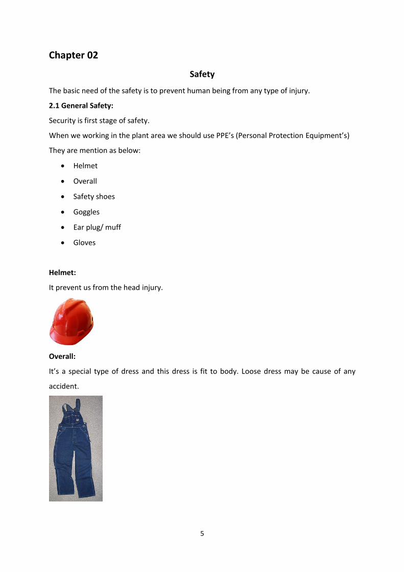
Helmet:
It prevent us from the head injury.
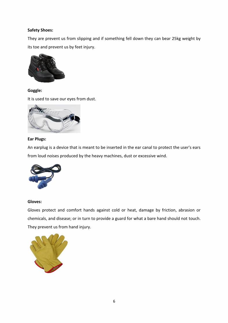
Overall:
It’s a special type of dress and this dress is fit to body. Loose dress may be cause of any
accident.
6
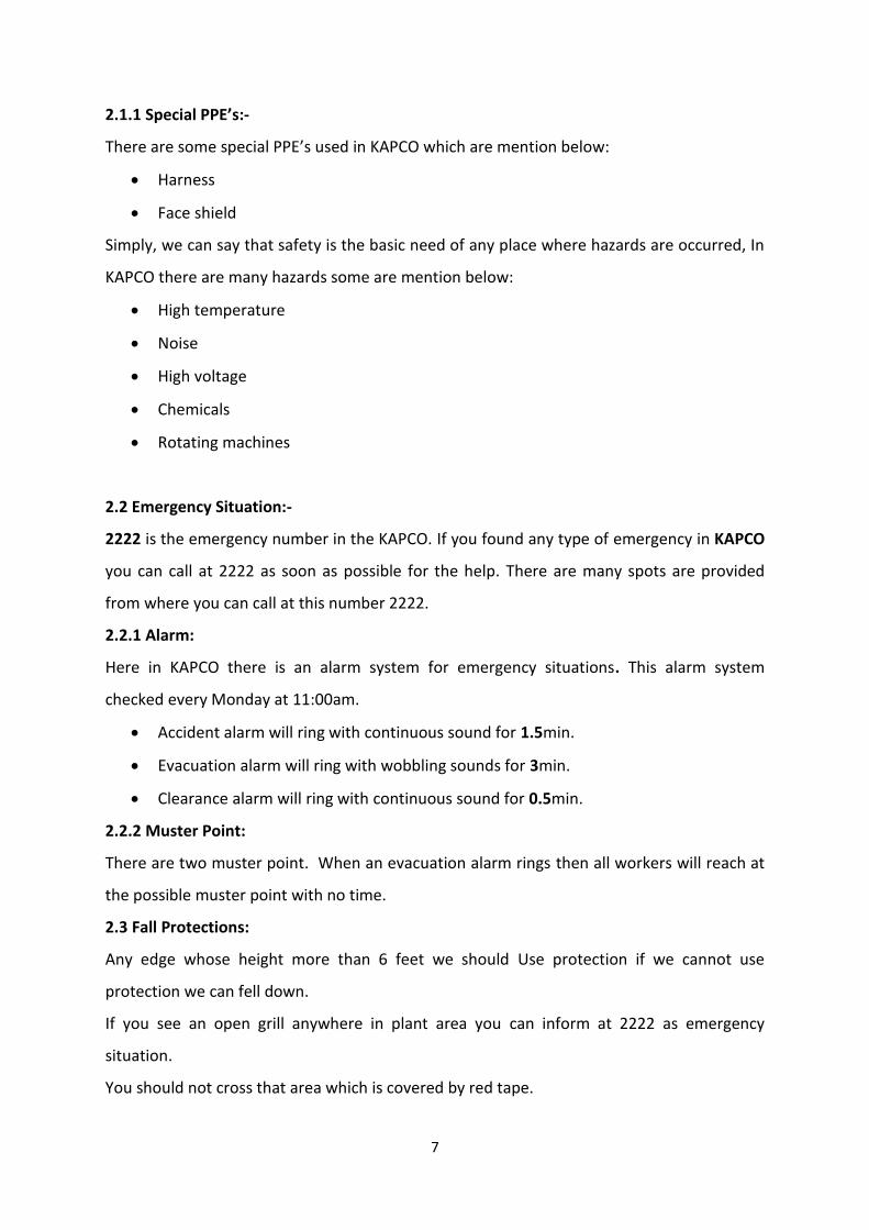
Safety Shoes:
They are prevent us from slipping and if something fell down they can bear 25kg weight by
its toe and prevent us by feet injury.
Goggle:
It is used to save our eyes from dust.
Ear Plugs:
An earplug is a device that is meant to be inserted in the ear canal to protect the user's ears
from loud noises produced by the heavy machines, dust or excessive wind.
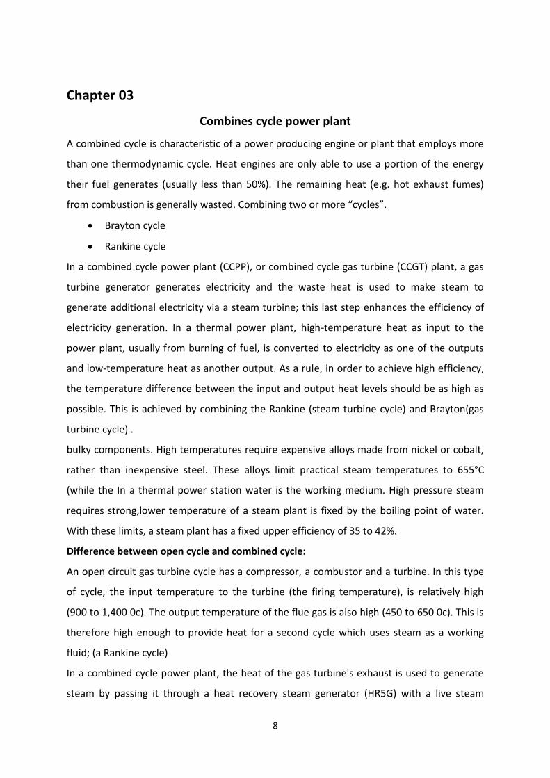
Gloves:
Gloves protect and comfort hands against cold or heat, damage by friction, abrasion or
chemicals, and disease; or in turn to provide a guard for what a bare hand should not touch.
They prevent us from hand injury.
7
2.1.1 Special PPE’s:-
There are some special PPE’s used in KAPCO which are mention below:
Harness
Face shield
Simply, we can say that safety is the basic need of any place where hazards are occurred, In
KAPCO there are many hazards some are mention below:
High temperature
Noise
High voltage
Chemicals
Rotating machines
2.2 Emergency Situation:-
2222 is the emergency number in the KAPCO. If you found any type of emergency in KAPCO
you can call at 2222 as soon as possible for the help. There are many spots are provided
from where you can call at this number 2222.
2.2.1 Alarm:
Here in KAPCO there is an alarm system for emergency situations. This alarm system
checked every Monday at 11:00am.
Accident alarm will ring with continuous sound for 1.5min.
Evacuation alarm will ring with wobbling sounds for 3min.
Clearance alarm will ring with continuous sound for 0.5min.
2.2.2 Muster Point:
There are two muster point. When an evacuation alarm rings then all workers will reach at
the possible muster point with no time.
2.3 Fall Protections:
Any edge whose height more than 6 feet we should Use protection if we cannot use
protection we can fell down.
If you see an open grill anywhere in plant area you can inform at 2222 as emergency
situation.
You should not cross that area which is covered by red tape.
8
Chapter 03
Combines cycle power plant
A combined cycle is characteristic of a power producing engine or plant that employs more
than one thermodynamic cycle. Heat engines are only able to use a portion of the energy
their fuel generates (usually less than 50%). The remaining heat (e.g. hot exhaust fumes)
from combustion is generally wasted. Combining two or more “cycles”.
Brayton cycle
Rankine cycle
In a combined cycle power plant (CCPP), or combined cycle gas turbine (CCGT) plant, a gas
turbine generator generates electricity and the waste heat is used to make steam to
generate additional electricity via a steam turbine; this last step enhances the efficiency of
electricity generation. In a thermal power plant, high-temperature heat as input to the
power plant, usually from burning of fuel, is converted to electricity as one of the outputs
and low-temperature heat as another output. As a rule, in order to achieve high efficiency,
the temperature difference between the input and output heat levels should be as high as
possible. This is achieved by combining the Rankine (steam turbine cycle) and Brayton(gas
turbine cycle) .
bulky components. High temperatures require expensive alloys made from nickel or cobalt,
rather than inexpensive steel. These alloys limit practical steam temperatures to 655°C
(while the In a thermal power station water is the working medium. High pressure steam
requires strong,lower temperature of a steam plant is fixed by the boiling point of water.
With these limits, a steam plant has a fixed upper efficiency of 35 to 42%.
Difference between open cycle and combined cycle:
An open circuit gas turbine cycle has a compressor, a combustor and a turbine. In this type
of cycle, the input temperature to the turbine (the firing temperature), is relatively high
(900 to 1,400 0c). The output temperature of the flue gas is also high (450 to 650 0c). This is
therefore high enough to provide heat for a second cycle which uses steam as a working
fluid; (a Rankine cycle)
In a combined cycle power plant, the heat of the gas turbine's exhaust is used to generate
steam by passing it through a heat recovery steam generator (HR5G) with a live steam
9
temperature between 420 and 580 0c. The condenser of the Rankine cycle is usually cooled
by water from a lake, river, sea or cooling towers. This temperature can be as low as 15 °C.
Combined cycle plants are usually powered by natural gas; although fuel oil, synthesis gas,
Furnace Oil, High speed diesel or other fuels can be used. The supplementary fuel may be
natural gas, fuel oil.
Combined cycle components:
Gas turbine
Heat recovery steam generator (HRSGs)
3.1 Gas turbine:
The major component of the combine cycle power plant is the gas turbine. In installation
where the gas turbine exhausts directly to the atmosphere, it is said to be operating in
“open cycle” mode. When a gas turbine exhausts into a heat recovery steam generator
(HRSG) the resultant steam is used to operate a steam turbine generator, the plant is
referred to as a combined cycle power plant.
A common arrangement of a gas turbine driving an electric generator is shown in figure. The
basic gas turbine consists of a compressor, a combustion chamber and a turbine. The air is
drawn into the compressor, which raise the pressure. The temperature also increases with
compression and may be as high as 350°C at the compressor discharge.
Main components of gas turbine:
Intake air filters
Compressor
Combustion chamber
Turbine
Exhaust diffuser
10
3.2 HEAT RECOVERY STEAM GENERATOR(HRSG)
The HRSG is basically a heat exchanger composed of a series of economiser,evaporator and
super heater sections.These sections are positioned from gas inlet to gas outlet to maximize
heat recovery from the gas turbine exhaust gases. The heat recovered in the HRSG is used to
supply steam to the steam turbine at the proper temperature and pressure.
In open cycle mode of operation,the temperature of exhaust gases of unit 1 and 2 leaving
KAPCO is 500° C to 550° C.
High temperature gas represents a source of heat energy,some of which can be recovered if
the means to do are available. By recovering some of this waste heat,the output and the
efficiency of a power plant is increased.
The function of heat recoThe function of heat recovery steam generator (HRSG) is to
recover the waste heat available in these exhaust gases and transfer that waste heat to
water and steam.The heat is used to generate steam at high pressure and high
temperature.The steam is then used to generate additional power in a steam turbine driven
generator.The HRSG provides the critical link between the gas turbine and the rankine cycle
in a combined cycle plant. The HRSG is a key component in combined cycle efficiency.
HP section
The HP section consists of Economizer, Evaporator, and Circulation system for economizer
and evaporator and Super heater.
LP section
The LP section consists of Evaporator and Circulation system for evaporator.
The re-circulating pumps cause the mechanically induced circulation in the boiler.
3.3 Generator:
Synchronous generator or alternator is used to convert mechanical energy into electrical
energy. Its working principle is as follows:
Working principle:
According to Faraday’s law of electromagnetic induction:
“If there is a relative motion between conductor and magnetic field, then an EMF will be
induced into the conductor”.
To create this relative movement, it doesn’t matter whether the magnet is rotating
and the conductor is stationary or weather the conductor is moving and magnet is
stationary.
11
The magnitude of the induced EMF is directly proportional to the No of conductors
(N) and the rate of change of magnetic flux crossing the conductors.
E = N (dΦ/dt)
Difference between AC generator and DC generator:
There is one important difference between an AC and DC generator. In DC Generator the
armature rotates but the field system remains stationary but in AC generator the case is
reverse because here armature remains stationary but field winding rotates.
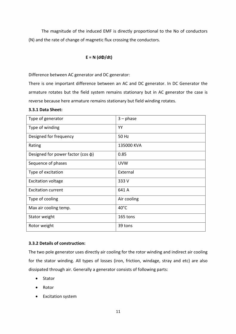
3.3.1 Data Sheet:
Type of generator 3 – phase
Type of winding YY
Designed for frequency 50 Hz
Rating 135000 KVA
Designed for power factor (cos φ) 0.85
Sequence of phases UVW
Type of excitation External
Excitation voltage 333 V
Excitation current 641 A
Type of cooling Air cooling
Max air cooling temp. 40°C
Stator weight 165 tons
Rotor weight 39 tons
3.3.2 Details of construction:
The two pole generator uses directly air cooling for the rotor winding and indirect air cooling
for the stator winding. All types of losses (iron, friction, windage, stray and etc) are also
dissipated through air. Generally a generator consists of following parts:
Stator
Rotor
Excitation system
12
Carbon brushes and Slip rings
Retaining rings
Bearing
Rotor grounding system
Cooling system
3.3.3 Stator:
It is a stationary part of the generator. The stator has two main components:
Stator frame
Magnetic core
Stator winding
Stator End shields
Stator frame:
The frame is for to support the laminated core and winding and also for to increase
the mechanical strength of the machine. It is the heaviest part of the generator. Air ducts
are provided for the rigidity of stator frame. End shields are also bolted to this frame. For
the foundation purposes feet are provided.
Magnetic core:
The stator core is stacked from insulated electrical sheet-steel laminations with a low
loss index and suspended in the stator frame from insulated guide bars.
The entire magnetic core is buildup of thin laminations in order to minimize the
hysteretic and eddy current losses of rotating magnetic field which interact with core. Each
lamination core is made up from a number of individual segments. The segments are
punched in one operation from .35 thick electrical sheet steel lamination having high silicon
content. The core is stacked with lamination segments in individual layers while being
supported on the pressure plate. The segments are staggered from layer to layer so that a
core of high mechanical strength and uniform permeability to magnetic flux is obtained. The
No of slots are created in the core to accommodate the stator winding. The complete stack
is kept under pressure and located in the frame by means of clamping bolts and pressure
plates.

13
If there is any damage to the core occur during operation, then Alcid test is
performed to check the insulation between layers.
Stator winding:
It is noble part of the generator. It is composed of conductors wedged into the magnetic
core. Each stator slot accommodates two bars. There are two distinct parts of stator
winding:
The straight part is within magnetic core.
The end winding which are outside the core and which serve to connect bars of different
slots together to complete the winding.
This winding is fractional pitch two layer type consisting of individual bars. In order to
minimize the stray losses, the bars are composed of insulated strands which are transposed
by 360°.
According to the Moralistic system, high voltage insulation is provided by which several half-
overlapped layers of mica are applied to the bars. The mica tapped is sandwiched between
two fabric layers with epoxy as an adhesive. The No of layers depends upon the machine
voltage.
This high voltage insulation obtained is characterized by excellent electrical,
mechanical and thermal properties in addition to being fully waterproof and oil resinant.
To minimize the Corona discharge between the insulation and the slot wall, a final
coat of semiconducting varnish is applied to the surface of all bars within the slot range.
Stator End shields
The stator end shields are attached to the end of the stator frame. It contains the
generator bearings and also the generator coolers. The generator coolers are
accommodated in the vertical wells of stator end shields.
The bearing oil is supplied to the bearing saddle via a piece permanently installed in
the end shield and is then passed on to the lubricating gap via ducts in the lower bearing
sleeve. The oil drained from the bearing is collected in the bearing compartment, then it is
discharged from the lower half of the end shield and then is returned to the turbine oil tank.
Electrical connection of bars and Phase connectors
Electrical connection between the top and bottom bars is made by brazing. One top
bar strand being brazed to one strand of associated bottom bar, so that the beginning of
each strand is connected without having any electrical contact with the remaining strands.
14
This connection offers the advantage that circulating current losses in the stator bars are
kept small.
The phase connectors consist of flat copper sections, the cross section of which
results in a low specific current loading. The ends of each phase are attached to the circular
phase connector, which leads from winding ends to the top of the frame. The phase
connectors are mounted on the winding support, using clamping pieces and glass fabric
tape.
3.3.4 Rotor:
It is the rotating part of the generator. It is driven by the turbine and it creates
rotating magnetic field. There are two types of rotor:
Cylindrical type
Salient-pole type
The cylindrical type rotor is used in turbo alternators and a having a uniform air gap.
Normally it is used in all types of thermal power stations where the rotating speed of rotor
is high like 3000 rpm in PAKISTAN. For 3000 rpm, it has two poles. The field winding is
accumulated in slots on the solid rotor.
Salient pole rotors are used for low speed operation like about 167 rpm for 50 Hz. For
this arrangement, we use 36 poles of the rotor.
Rotor has the following main components:
Rotor shaft:
The rotor shaft is made of single gorging whose ingot is made in an electric furnace
and then vacuum cast. The rotor consists of an electrically active portion and the two shaft
ends. A forged coupling is used to couple the rotor to the turbine. The longitudinal slots hold
the field winding. Slot pitch is selected so that two solid poles are displaced by 180°
electrical. In these slots field coils are milled into shaft body and is arranged so as to
generate magneto motive force wave approaching a sine wave.
Rotor teeth are provided with axial and radial ducts enabling the cooling air to be
discharged into the air gap for intensive cooling of the end winding.
15
Rotor winding:
Rotor winding has also two distinct parts:
The shaft contained in shaft body.
The part outside the shaft body.
The rotor winding consists of several coils which are inserted into the slots and series
connected such that two coil groups form one pole. Each coil consists of several series
connected turns, each of which consists of two half turns which are connected by brazing in
the end section.
The insulated turns are insulated from each other by strips of laminated glass fabric.
The edges of slots is made up of high conductivity material and they are there to act as
damper winding. At the ends the clots are short circuited by retaining rings.
3.3.5 Excitation system:
The excitation system is to supply the direct current to rotor which allows the
generator to maintain a controlled voltage between it’s terminals when connected to the
network. The excitation system is driven by a voltage regulator. The excitation power for the
generator is supplied by an exciter with rotating diodes that are fitted at the end of main
generator shaft.
The excitation voltage is developed by rotating diode bridge that supplies the rotor
winding. These rectifying diodes are given supply by an excitation transformer of which the
primary winding is supplied by the main generator. Then the secondary winding is rectified
by a three phase thyrister bridge.
The excitation equipment, Slip ring, and carbon brushes are used to supply the
excitation current to the rotor.
If there comes a need to change the brushes of the machine during operation at full
load or any load, brush gear assembly is used to do this job.
During start up and in case of stator voltage drop, the excitation power is supplied by
220 V DC source. De- excitation of the generator is performed by the opening of the
excitation contactor and a non linear resistor ensures the discharging of the exciter.
Excitation connection:
16
The current supplied by excitation unit to the rotor winding is sent through D bars
(central shaft connection), radial connecting rod, and outer axial connection that feed
directly into the winding.
It is made up of two D shaped solid bars, separated by a layer of insulation and
housed in shaft bore.
Carbon brushes and two slip rings arranged at the end of the shaft. The electrical
connection between slip rings and rotor winding is established by means of radial bolts and
insulated conductors arranged in hollow bore of rotor at the exciter end.
3.3.6 Carbon brushes and slip rings:
Field connection provides electrical connection between rotor winding and slip ring.
Steel slip rings are fitted to the shaft extension at the non-drive end and insulated
from the end. The slip ring contains a uniform current distribution.
Carbon brushes are used to make live connection between the excitation system and rotor
winding, because our rotor is moving continuously and this is the only option to make such a
connection.
The slip rings have axial and radial holes for ventilation of slip ring. This forced ventilation
system ensure the removal of carbon dust sue to brush wear.
3.3.7 Retaining ring:
The end winding which are extend beyond the shaft body are held against centrifugal
forces by retaining ring of nonmagnetic steel cylinders.
One end of each ring is shrunk on the rotor body, while other end of the ring over
hangs the end winding without contacting the shaft.
The shrunk on the end ring at the free end of the retaining ring serves to reinforce
the retaining ring and also secures the winding in the axial direction.
A snap ring is provided for additional protection against axial displacement of the
retaining ring.
To reduce the straw losses the ring is made up of non-magnetic material. Comprehensive
tests such as ultra-sonic examination and liquid penetration examination ensure the
specified mechanical properties.
17
3.3.7 Bearings:
Bearing are used to lift the shaft, to make the vibration of rotor as small as possible
and to make the friction during the movement of the shaft. As shaft is connected with
bearing, this shaft is lifted by oil flowing in the bearing.
Ta main purpose of using oil in these bearings is cooling of bearings which are heated
because of running of the shaft. Friction is also reduced when we use oil in the bearing.
To eliminate the shaft currents, all bearings are insulated from the stator and base plate
respectively. The temperature of the bearing is monitored by thermocouples mounted in
the lower bearing part so that the measuring points are located directly below the Babbitt.
3.3.8 Rotor grounding:
Grounding system is necessary thing to make the generator grounded because when
we are working at the generator then flux or static charge which was stored in the rotor
winding during operation is needed to be grounded. That flux can be harmful if not
grounded
Grounding brushes are fitted to the stator end shield.
3.3.9 Generator cooling system
The heat losses arising in the generator interior are dissipated to the secondary
coolant (cooling water) through air. Direct cooling of rotor removes hot spots and
differential temperature between the adjacent components. Indirect cooling is used for
stator winding.
Air and hydrogen are two cooling media for the generator cooling. The field and
armature copper losses are evacuated by air/ hydrogen gas flowing inside the generator.
The axial fans circulate the air. In KAPCO all generators are air cooled.
Advantages of Air cooling
1. lower cost price
2. Easy maintenance
3. Short inspection
18
3.3.10 Advantages of hydrogen cooling system
1. Windage losses of the rotor turning are only 1% of those in air.
2. The higher thermal conductivity of Hydrogen allows generator to develop 25% more
output than those of air.
3. Hydrogen increases the life of generator because of the absence of Oxygen.
4. The η of generator can be taken as 98% with air cooling and 99% with hydrogen
cooling.
3.3.11 Drawbacks of Hydrogen cooling
1. Generator body must be gas tight.
2. Special type of oil seal is used on the bearing to stop the leakage of Hydrogen.
3. Precaution should be taken to prevent any air leakage into the machine.
4. A mixture of air and hydrogen inside the machine casing is risky and may cause in
explosion
3.3.12 Stator cooling:
The magnetic core is cooled by the air flowing through the radial vent ducts under the
action of the fans. The vent ducts are formed by splitting up the core, along it’s whole length
into packets separated from each other by radial spacer ribs. Core cooling is thus of radial
type.
The current flowing through the stator winding creates heat losses which are
escaped to the core due to close contact between the winding and core. This is called
indirect cooling. The end winding area is cooled circulation of air.
3.3.13 Rotor cooling:
The main rotor heat losses occur in the field winding. It is dissipated by direct contact
with air flowing through the coil. The slot portion of the winding is cooled circulating air.
All rotor winding is subdivided into four cooling zones. One cooling zone includes the
slots from center to the end of the rotor body, while another cover s half of the end
winding.
19
This generator is now connected to the unit transformer converting the out put voltage into
132 kv(block 1) or 220 kv (block 2 & 3) which then goes to the switch yard for the
transmission purposes.
The cooling air for the slot portion is admitted into the slot bottom ducts below the
rotor winding. The hot air is then discharged into the air gap between the rotor body and
stator sore though radial opening in the conductors and in the rotor slot wedges.
The cooling air is drawn from below the rotor end winding. It rises radially along the
individual coils and is then discharged into the air gap via axial and radial slots in the end
portion of the rotor teeth.
3.3.13 End winding cooling
The end winding cooling circuit is independent of the slot portion cooling circuit. Part
of the cold air passing under the end winding flows through the space between coil. Cold air
enters through longitudinal ducts and warm air flows to the air gap through radial ducts.
3.3.14 Air cooling circuit
Cooling air is circulated in the generator by two axial-flow fans on the rotor shaft.
Cold air is drawn by fans from cooler and then divided into three parts.
Flow path 1:
Is directed into the rotor end winding and cools the rotor winding. Along this
path heat of the rotor winding is directly transferred to the cooling air.
Flow path 2:
Is directed over the stator end winding to the cold air ducts and in the stator frame
space between the generator housing and the stator core.
Flow path 3:
Is directed into the air gap via the rotor retaining rings. This path mainly cools the rotor
retaining rings, the end of the rotor body and end portion of the stator frame.
Then this flow of air is mixed up in air gap from where it goes for the cooling of the other
remaining portion of the stator core and the stator winding. The hot air is returned to the
cooler via hot air ducts recooling and draw again by the fans.
Air cooler:
20
Air cooler is shell and tube type heat exchanger which cools the air in the generator.
Four identical coolers are provided. The stator end shields contain the vertically mounted
coolers. The cooler section is solidly bolted to the upper half of the stator end shield. All four
coolers are parallel connected on their water side. The required cooling water flow depends
on the generator output and is adjusted by control valves on the hot water side.
3.3.15 Abnormalities in generators:
Abnormal conditions that may occur with rotating elements include the following:
Faults in windings
Overheating of winding
Over speed
Over load
Loss of excitation
Motoring of generator
Unbalance current operation
Out of step
Several of these conditions do not require that the unit is tripped automatically; they can be
corrected while the machine remains in service. These conditions are signaled by alarms.
Other conditions, however, such as faults, require prompt removal of the machine from
service
21
Chapter 04
Transformers
A transformer is a static machine used for transforming power from one circuit to another
without changing frequency. This is very basic definition of transformer.
4.1 Working Principle of transformer
The working principle of transformer is very simple. It depends upon Faraday’s laws of
Electromagnetic Induction. Actually mutual induction between two or more winding is
responsible for transformation action in an electrical transformer.
4.2 Faraday’s laws of Electromagnetic Induction
According to these Faraday’s laws,
"Rate of change of flux linkage with respect to time is directly proportional to the induced
EMF in a conductor or coil".
e= M dI / dt
where
e = Induced voltage
M = mutual inductance
dI = rete of change in the current
dt = rate of change in time
If the circuit of the second coil is closed, current flows in it and so in this way electric energy
is transferred from one coil to the coil. The first coil in which electric supply is connected is
called the primary coil and other coil to which the power is supplied is called the secondary
coil. In a brief transformer is a device that
4.3 Transfers electric power form one circuit to the other:
It does so without change in frequency.
It accomplishes it by the electromagnetic induction.
Where two circuits are electrically isolated but magnetically coupled.
22
4.4 Voltage Ratio of Transformer:
This above said ratio is also known as voltage ratio of transformer if it is expressed as ratio
of the primary and secondary voltages of transformer.
4.5 Turns Ratio of Transformer:
As the voltages in primary and secondary of transformer is directly proportional to number
of turns in the respective winding, the transformation ratio of transformer is sometime
expressed in ratio of turns and referred as turns ratio of transformer.
4.6 Types of the transformer
In all types of transformer, the core is constructed of transformer sheets, steel laminations
to provide a continuous magnetic path with minimum air gap. Transformers are classified by
several means,
According to Construction.
According function.
According to consumer.
According to connections.
4.6.1 According to Construction:
Construction ally, transformers are of two general types.
Shell type.
Core type.
4.6.2 According to functions:
Power transformer
4.6.2.1 Power transformer:
Two winding transformer
Three winding transformer
Auto transformer
4.6.2.2Special transformer:
CT (Current Transformer)
PT (Potential Transformer)
23
4.6.3 According to consumer
Transformers are also classified by means that how a consumers uses it.
Step up transformer
Here turns of secondary are large then that of primary. i.e. output voltage is greater than
input voltage but on the other hand, primary current is large than that of secondary.
Step down transformer
Here reverse process takes place than that of the step up transformer.
Generally following type of transformers are used in our power house.
24
Chapter 05
Switch Yard
Inside the switch yard
Mainly there are different but most important things for the protection, measurement,
metering and for the other purposes.
Circuit Breaker
Isolator
Insulator
Insulator strings
Bus Bar
Current transformer (C.T.)
Potential transformer (P.T.)
Conductor
Control Switch
Relays
There are different type of schemes are used but in our block III one and half scheme is
used.
ONE AND HALF SCHEME:
The benefit of this scheme is that if for example any fault occurs on any bus bar then the
supply of the feeder will not disconnect. Then the supply will go to the second bus bar
without an interruption.
CIRCUIT BREAKER:
As we know circuit breaker is an on load device it means that it can do proper work and do
ON and OFF with safety due to supply. In these circuit breaker we used SF6 for arc
quenching medium and these circuit breaker are air operated. And the air pressure becomes
18 bar.
25
ISOLATERS:
While isolators are off load device means that it just like work as a fuse it do work only at off
supply. Because it did not keep any arc quenching medium if we use at an on load supply
then it will become damage ,So every bay consists of six isolators three circuit breaker and
three current transformers, which measure the current and give protection. One isolator is
used for generator protection it is installed in start of the bay.
CURRENT TRANSFORMER:
We also use the current transformer in Series of every bay. There are five coils of CT and
three basic purposes of using CT.
Measurement of the current.
Protection of the relays and breakers etc.
Metering
For the Breaker failure protection.
POTENTIAL TRANSFORMER:
We also use the potential transformer in parallel of the bus bar. It is used to measure the
voltages and it has been installed with the bus bar to measure the voltage across the bus
bar.
We are checking for high voltage and low voltage but carefully for the low voltage because
the auxiliaries which we are running from this voltage will draw very high current if the
voltage is very low and this can damage our equipment.
So, we keep on checking for the low voltage and the high voltage. We have to use P.T.
because we can’t design such a big voltmeter.
BUS BAR:
Now we discussed about the bus bars we are using two bus bars in KAPCO power plant, first
of all we will define bus bar
“Bus bar is a conducting piece of bar which connect among the source and the distribution
circuit”
It work as a medium between feeder and source. The bus bar voltages remain same. So the
six feeders go out from the KAPCO power plant of 220KV and the six are 132KV.
26
Relays:
These are operated by taking information from C.T. and P.T. Each and every thing of the
system even in the switchyard is being protected by relays because they are made very
much sensitive for the faults. They sense every fault for which it has been designed and then
some other important devices are operated from the signal of the relay.
There are many types of the relays,
Differential over current relay.
Over current relay.
Over and under voltage relay.
Directional over current relay.
Similarly there are many other types of the relays which we will discuss later.