+k8n4-e deluxe front
TRANSCRIPT

Mot
herb
oard
K8N4-EDeluxe

i ii ii ii ii i
Copyright © 2005 ASUSTeK COMPUTER INC. All Rights Reserved.No part of this manual, including the products and software described in it, may be reproduced,transmitted, transcribed, stored in a retrieval system, or translated into any language in any formor by any means, except documentation kept by the purchaser for backup purposes, without theexpress written permission of ASUSTeK COMPUTER INC. (“ASUS”).
Product warranty or service will not be extended if: (1) the product is repaired, modified oraltered, unless such repair, modification of alteration is authorized in writing by ASUS; or (2)the serial number of the product is defaced or missing.
ASUS PROVIDES THIS MANUAL “AS IS” WITHOUT WARRANTY OF ANY KIND, EITHEREXPRESS OR IMPLIED, INCLUDING BUT NOT LIMITED TO THE IMPLIED WARRANTIESOR CONDITIONS OF MERCHANTABILITY OR FITNESS FOR A PARTICULAR PURPOSE.IN NO EVENT SHALL ASUS, ITS DIRECTORS, OFFICERS, EMPLOYEES OR AGENTS BELIABLE FOR ANY INDIRECT, SPECIAL, INCIDENTAL, OR CONSEQUENTIAL DAMAGES(INCLUDING DAMAGES FOR LOSS OF PROFITS, LOSS OF BUSINESS, LOSS OF USEOR DATA, INTERRUPTION OF BUSINESS AND THE LIKE), EVEN IF ASUS HAS BEENADVISED OF THE POSSIBILITY OF SUCH DAMAGES ARISING FROM ANY DEFECT ORERROR IN THIS MANUAL OR PRODUCT.
SPECIFICATIONS AND INFORMATION CONTAINED IN THIS MANUAL ARE FURNISHEDFOR INFORMATIONAL USE ONLY, AND ARE SUBJECT TO CHANGE AT ANY TIMEWITHOUT NOTICE, AND SHOULD NOT BE CONSTRUED AS A COMMITMENT BY ASUS.ASUS ASSUMES NO RESPONSIBILITY OR LIABILITY FOR ANY ERRORS ORINACCURACIES THAT MAY APPEAR IN THIS MANUAL, INCLUDING THE PRODUCTSAND SOFTWARE DESCRIBED IN IT.
Products and corporate names appearing in this manual may or may not be registeredtrademarks or copyrights of their respective companies, and are used only for identification orexplanation and to the owners’ benefit, without intent to infringe.
E2009E2009E2009E2009E2009
Revis ion Edit ion V2Revis ion Edit ion V2Revis ion Edit ion V2Revis ion Edit ion V2Revis ion Edit ion V2March 2005March 2005March 2005March 2005March 2005

i i ii i ii i ii i ii i i
Contents
Notices ............................................................................................... vii
Safety information ............................................................................ viii
About this guide ................................................................................. ix
K8N4-E Deluxe specifications summary .............................................. xi
Chapter 1:Chapter 1:Chapter 1:Chapter 1:Chapter 1: Product introductionProduct introductionProduct introductionProduct introductionProduct introduction
1.1 Welcome! .............................................................................. 1-1
1.2 Package contents ................................................................. 1-1
1.3 Special features .................................................................... 1-2
1.3.1 Product highlights ................................................... 1-2
1.3.2 ASUS Proactive feature .......................................... 1-5
1.3.3 Innovative ASUS features ....................................... 1-5
Chapter 2:Chapter 2:Chapter 2:Chapter 2:Chapter 2: Hardware informationHardware informationHardware informationHardware informationHardware information
2.1 Before you proceed .............................................................. 2-1
2.2 Motherboard overview .......................................................... 2-2
2.2.1 Placement direction ................................................ 2-2
2.2.2 Screw holes ............................................................ 2-2
2.2.3 Motherboard layout ................................................ 2-3
2.2.4 Layout Contents ..................................................... 2-4
2.3 Central Processing Unit (CPU) .............................................. 2-6
2.4 System memory ................................................................... 2-8
2.4.1 Overview ................................................................. 2-8
2.4.2 Memory Configurations ........................................... 2-8
2.4.3 Installing a DDR DIMM ........................................... 2-12
2.4.4 Removing a DDR DIMM .......................................... 2-12
2.5 Expansion slots ................................................................... 2-13
2.5.1 Installing an expansion card .................................. 2-13
2.5.2 Configuring an expansion card .............................. 2-13
2.5.3 Interrupt assignments .......................................... 2-14
2.5.4 PCI slots ................................................................ 2-15
2.5.5 PCI Express x16 slot ............................................. 2-15
2.5.6 PCI Express x1 slot ............................................... 2-15

i vi vi vi vi v
Contents
2.6 Jumpers .............................................................................. 2-16
2.7 Connectors ......................................................................... 2-18
2.7.1 Rear panel connectors .......................................... 2-18
2.7.2 Internal connectors ............................................... 2-20
Chapter 3:Chapter 3:Chapter 3:Chapter 3:Chapter 3: Powering upPowering upPowering upPowering upPowering up
3.1 Starting up for the first time ................................................ 3-1
3.2 Powering off the computer .................................................. 3-2
3.2.1 Using the OS shut down function ........................... 3-2
3.2.2 Using the dual function power switch .................... 3-2
3.3 ASUS POST Reporter™ .......................................................... 3-3
3.3.1 Vocal POST messages ............................................ 3-3
3.3.2 Winbond Voice Editor ............................................. 3-5
Chapter 4:Chapter 4:Chapter 4:Chapter 4:Chapter 4: BIOS setupBIOS setupBIOS setupBIOS setupBIOS setup
4.1 Managing and updating your BIOS ........................................ 4-1
4.1.1 Creating a bootable floppy disk .............................. 4-1
4.1.2 AwardBIOS Flash Utility .......................................... 4-2
4.1.3 ASUS EZ Flash utility .............................................. 4-6
4.1.4 ASUS CrashFree BIOS 2 utility ................................ 4-7
4.1.5 ASUS Update utility ................................................ 4-8
4.2 BIOS Setup program ........................................................... 4-11
4.2.1 BIOS menu bar ...................................................... 4-12
4.2.2 Legend bar ........................................................... 4-12
4.3 Main Menu........................................................................... 4-14
4.3.1 System Time......................................................... 4-14
4.3.2 System Date ......................................................... 4-14
4.3.3 Language .............................................................. 4-14
4.3.4 Legacy Diskette A ................................................ 4-14
4.3.5 HDD SMART Monitoring ........................................ 4-15
4.3.6 Installed Memory .................................................. 4-15
4.3.7 Primary and Secondary IDE Master/Slave ............. 4-15
4.3.8 First, Second, Third, and Fourth SATA Master ..... 4-17
vvvvv
Contents
4.4 Advanced Menu .................................................................. 4-19
4.4.1 CPU configuration ................................................. 4-20
4.4.2 PCIPnP ................................................................... 4-22
4.4.3 Onboard device configuration ............................. 4-24
4.4.4 JumperFree Configuration .................................... 4-30
4.4.5 LAN Cable Status ................................................. 4-32
4.4.6 PEG Link Mode ...................................................... 4-33
4.4.7 Speech Configuration ........................................... 4-34
4.4.8 Instant Music ........................................................ 4-35
4.5 Power Menu ........................................................................ 4-36
4.5.1 ACPI Suspend Type............................................... 4-36
4.5.2 ACPI APIC Support ................................................ 4-36
4.5.3 APM configuration ................................................ 4-37
4.5.4 Hardware monitor ................................................. 4-40
4.6 Boot Menu .......................................................................... 4-41
4.6.1 Boot Device Priority .............................................. 4-41
4.6.2 Removable drives ................................................. 4-42
4.6.3 Hard Disk Drives ................................................... 4-42
4.6.4 CD-ROM drives ...................................................... 4-43
4.6.5 Boot settings configuration .................................. 4-43
4.6.6 Security ................................................................ 4-45
4.7 Exit menu ........................................................................... 4-46
v iv iv iv iv i
Contents
Chapter 5:Chapter 5:Chapter 5:Chapter 5:Chapter 5: Software supportSoftware supportSoftware supportSoftware supportSoftware support
5.1 Installing an operating system ............................................. 5-1
5.2 Support CD information ........................................................ 5-1
5.2.1 Running the support CD ......................................... 5-1
5.2.2 Drivers menu .......................................................... 5-2
5.2.3 Utilities menu .......................................................... 5-3
5.2.4 Manuals menu ......................................................... 5-5
5.2.5 ASUS Contact information ...................................... 5-6
5.2.6 Other information ................................................... 5-6
5.3 Software information ........................................................... 5-8
5.3.1 ASUS MyLogo2™ .................................................... 5-8
5.3.2 AI NET2 ................................................................ 5-10
5.3.3 ASUS Instant Music ............................................... 5-11
5.3.4 Cool ‘n’ Quiet!™ Technology ................................. 5-14
5.3.5 Audio configurations ............................................ 5-17
5.3.6 Using the NVIDIA® Firewall™ ................................. 5-24
5.3.7 Using the NVIDIA® nTune™ utility ......................... 5-27
5.4 RAID configurations ............................................................ 5-31
5.4.1 Installing hard disks .............................................. 5-32
5.4.2 NVIDIA® RAID configurations ................................ 5-33
5.4.3 Silicon Image RAID configurations ........................ 5-40
5.5 Creating a RAID driver disk ................................................. 5-50

v i iv i iv i iv i iv i i
Notices
Federal Communications Commission StatementFederal Communications Commission StatementFederal Communications Commission StatementFederal Communications Commission StatementFederal Communications Commission Statement
This device complies with Part 15 of the FCC Rules. Operation is subject tothe following two conditions:
• This device may not cause harmful interference, and
• This device must accept any interference received including interferencethat may cause undesired operation.
This equipment has been tested and found to comply with the limits for aClass B digital device, pursuant to Part 15 of the FCC Rules. These limits aredesigned to provide reasonable protection against harmful interference in aresidential installation. This equipment generates, uses and can radiate radiofrequency energy and, if not installed and used in accordance withmanufacturer’s instructions, may cause harmful interference to radiocommunications. However, there is no guarantee that interference will notoccur in a particular installation. If this equipment does cause harmfulinterference to radio or television reception, which can be determined byturning the equipment off and on, the user is encouraged to try to correctthe interference by one or more of the following measures:
• Reorient or relocate the receiving antenna.
• Increase the separation between the equipment and receiver.
• Connect the equipment to an outlet on a circuit different from that towhich the receiver is connected.
• Consult the dealer or an experienced radio/TV technician for help.
Canadian Department of Communications StatementCanadian Department of Communications StatementCanadian Department of Communications StatementCanadian Department of Communications StatementCanadian Department of Communications Statement
This digital apparatus does not exceed the Class B limits for radio noiseemissions from digital apparatus set out in the Radio InterferenceRegulations of the Canadian Department of Communications.
This class B digital apparatus complies with CanadianThis class B digital apparatus complies with CanadianThis class B digital apparatus complies with CanadianThis class B digital apparatus complies with CanadianThis class B digital apparatus complies with CanadianICES-003.ICES-003.ICES-003.ICES-003.ICES-003.
The use of shielded cables for connection of the monitor to the graphicscard is required to assure compliance with FCC regulations. Changes ormodifications to this unit not expressly approved by the partyresponsible for compliance could void the user’s authority to operatethis equipment.

v i i iv i i iv i i iv i i iv i i i
Safety information
Electrical safetyElectrical safetyElectrical safetyElectrical safetyElectrical safety
• To prevent electrical shock hazard, disconnect the power cable from theelectrical outlet before relocating the system.
• When adding or removing devices to or from the system, ensure that thepower cables for the devices are unplugged before the signal cables areconnected. If possible, disconnect all power cables from the existingsystem before you add a device.
• Before connecting or removing signal cables from the motherboard,ensure that all power cables are unplugged.
• Seek professional assistance before using an adapter or extension cord.These devices could interrupt the grounding circuit.
• Make sure that your power supply is set to the correct voltage in yourarea. If you are not sure about the voltage of the electrical outlet you areusing, contact your local power company.
• If the power supply is broken, do not try to fix it by yourself. Contact aqualified service technician or your retailer.
Operation safetyOperation safetyOperation safetyOperation safetyOperation safety
• Before installing the motherboard and adding devices on it, carefully readall the manuals that came with the package.
• Before using the product, make sure all cables are correctly connectedand the power cables are not damaged. If you detect any damage,contact your dealer immediately.
• To avoid short circuits, keep paper clips, screws, and staples away fromconnectors, slots, sockets and circuitry.
• Avoid dust, humidity, and temperature extremes. Do not place theproduct in any area where it may become wet.
• Place the product on a stable surface.
• If you encounter technical problems with the product, contact a qualifiedservice technician or your retailer.
i xi xi xi xi x
About this guide
This user guide contains the information you need when installing andconfiguring the motherboard.
How this guide is organizedHow this guide is organizedHow this guide is organizedHow this guide is organizedHow this guide is organized
This user guide contains the following parts:
••••• Chapter 1: Product introduct ionChapter 1: Product introduct ionChapter 1: Product introduct ionChapter 1: Product introduct ionChapter 1: Product introduct ion
This chapter describes the features of the motherboard and the newtechnology it supports.
••••• Chapter 2: Hardware informat ionChapter 2: Hardware informat ionChapter 2: Hardware informat ionChapter 2: Hardware informat ionChapter 2: Hardware informat ion
This chapter lists the hardware setup procedures that you have toperform when installing system components. It includes description ofthe switches, jumpers, and connectors on the motherboard.
••••• Chapter 3: Power ing upChapter 3: Power ing upChapter 3: Power ing upChapter 3: Power ing upChapter 3: Power ing up
This chapter describes the power up sequence, the vocal POSTmessages, and ways of shutting down the system.
••••• Chapter 4: B IOS setupChapter 4: B IOS setupChapter 4: B IOS setupChapter 4: B IOS setupChapter 4: B IOS setup
This chapter tells how to change system settings through the BIOSSetup menus. Detailed descriptions of the BIOS parameters are alsoprovided.
••••• Chapter 5: Software supportChapter 5: Software supportChapter 5: Software supportChapter 5: Software supportChapter 5: Software support
This chapter describes the contents of the support CD that comeswith the motherboard package.
Where to find more informationWhere to find more informationWhere to find more informationWhere to find more informationWhere to find more information
Refer to the following sources for additional information and for productand software updates.
1 .1 .1 .1 .1 . ASUS webs itesASUS webs itesASUS webs itesASUS webs itesASUS webs ites
The ASUS website provides updated information on ASUS hardwareand software products. Refer to the ASUS contact information.
2 .2 .2 .2 .2 . Opt ional documentat ionOpt ional documentat ionOpt ional documentat ionOpt ional documentat ionOpt ional documentat ion
Your product package may include optional documentation, such aswarranty flyers, that may have been added by your dealer. Thesedocuments are not part of the standard package.

xxxxx
Conventions used in this guideConventions used in this guideConventions used in this guideConventions used in this guideConventions used in this guide
To make sure that you perform certain tasks properly, take note of thefollowing symbols used throughout this manual.
TypographyTypographyTypographyTypographyTypography
Bo l d t e x tBo l d t e x tBo l d t e x tBo l d t e x tBo l d t e x t Indicates a menu or an item to select.
Italics Used to emphasize a word or a phrase.
<Key> Keys enclosed in the less-than and greater-than sign meansthat you must press the enclosed key.
Example: <Enter> means that you must press the Enter orReturn key.
<Key1+Key2+Key3> If you must press two or more keys simultaneously, the
key names are linked with a plus sign (+).
Example: <Ctrl+Alt+D>
Command Means that you must type the command exactly as shown,then supply the required item or value enclosed inbrackets.
Example: At the DOS prompt, type the command line:afudos /i[filename]afudos /iK8N4-E.ROM
DANGER/WARNING: DANGER/WARNING: DANGER/WARNING: DANGER/WARNING: DANGER/WARNING: Information to prevent injury to yourselfwhen trying to complete a task.
CAUTION:CAUTION:CAUTION:CAUTION:CAUTION: Information to prevent damage to the componentswhen trying to complete a task.
NOTE: NOTE: NOTE: NOTE: NOTE: Tips and additional information to help you complete atask.
IMPORTANT: IMPORTANT: IMPORTANT: IMPORTANT: IMPORTANT: Instructions that you MUST follow to complete atask.

x ix ix ix ix i
K8N4-E Deluxe specifications summary
C P UC P UC P UC P UC P U
Ch ipsetCh ipsetCh ipsetCh ipsetCh ipset
System busSystem busSystem busSystem busSystem bus
MemoryMemoryMemoryMemoryMemory
Expans ion s lotsExpans ion s lotsExpans ion s lotsExpans ion s lotsExpans ion s lots
Sto rageSto rageSto rageSto rageSto rage
A I Aud ioA I Aud ioA I Aud ioA I Aud ioA I Aud io
IEEE 1394aIEEE 1394aIEEE 1394aIEEE 1394aIEEE 1394a
U S BU S BU S BU S BU S B
L A NL A NL A NL A NL A N
BIOS featuresB IOS featuresB IOS featuresB IOS featuresB IOS features
ASUS AI ProactiveASUS AI ProactiveASUS AI ProactiveASUS AI ProactiveASUS AI ProactiveFeatureFeatureFeatureFeatureFeature
(continued on the next page)
Socket 754 for AMD Athlon™ 64/AMD Sempron™processors
AMD64 architecture enables simultaneous 32- and64-bit computing
Supports AMD Cool ‘n’ Quiet™ Technology
NVIDIA® nForce™4-4X
1600 MT per second
3 x 184-pin DIMM sockets support unbufferred non-ECC400/333/266 MHz DDR memory modules
Suppports up to 3GB system memory
1 x PCI Express™ x16 slot for discrete graphics card3 x PCI Express™ x1 slots3 x PCI slots
NVIDIA® nForce™4-4X chipset supports:- 4 x Ultra DMA 133/100/66/33 hard disks- 4 x Serial ATA hard disks with RAID 0, RAID 1,
RAID 0+1, and JBOD configurations
Silicon Image Sil3114 RAID controller supports:- 4 x Serial ATA 1 hard disks with RAID 0, RAID 1,
RAID 10, and RAID 5 configurations
Realtek® ALC850 High Definition Audio solutionwith 8-channel CODEC
Audio Sensing and Enumeration Technology support3 x Universal Audio Jacks (UAJ®)1 x Coaxial S/PDIF out port1 x Optical S/PDIF out port
T1 IEEE 1394a controller supports two IEEE 1394a ports
Supports up to 10 USB 2.0 ports
Marvell® 88E81111 Gigabit LAN PHYSupports Marvell® Virtual Cable Tester Technology
4 Mb Flash ROM, Phoenix-AWARD BIOS, PnP, DMI2.0,SM BIOS 2.3, WfM2.0
AI NET 2

x i ix i ix i ix i ix i i
ASUS CrashFree BIOS 2ASUS Instant MusicASUS Q-Fan 2ASUS POST ReporterASUS Multi-language BIOSASUS MyLogo™ 2NVIDIA® Firewall
ASUS AI Overclocking (intelligent CPU frequency tuner)ASUS PEG Link for single graphics cardASUS C.P.R. (CPU Parameter Recall)Precision Tweaker:
- DIMM voltage: 9-step DRAM voltage control- vCore: Adjustable CPU voltage at 0.0125
increment- Stepless Frequency Selection (SFS) allows FSB
tuning from 200 MHz up to 400 MHz at 1 MHzincrement
- PCIe Frequency allows PCI Express frequencyadjustment from 100 MHz up to 200 MHz at1 MHz increment
1 x Floppy disk drive connector1 x Primary IDE connector1 x Secondary IDE connector4 x Serial ATA connectors4 x Serial ATA RAID connectors1 x CPU fan connector1 x Chipset fan connector2 x Chassis fan connectors1 x Power fan connector3 x USB 2.0 connectors1 x IEEE 1394a connector1 x 24-pin ATX power connector1 x 4-pin ATX 12 V power connector1 x CD audio connector1 x AUX connector1 x Game/MIDI port connector1 x Chassis intrusion connector1 x Front panel audio connector1 x System panel connector
K8N4-E Deluxe specifications summary
Spec ia l featuresSpec ia l featuresSpec ia l featuresSpec ia l featuresSpec ia l features
Overc lock ingOverc lock ingOverc lock ingOverc lock ingOverc lock ingfeatu resfeatu resfeatu resfeatu resfeatu res
In te rna lI n te rna lI n te rna lI n te rna lI n te rna lconnectorsconnectorsconnectorsconnectorsconnectors
(continued on the next page)

x i i ix i i ix i i ix i i ix i i i
*Specifications are subject to change without notice.
1 x PS/2 mouse port1 x Parallel port1 x IEEE 1394a port1 x LAN (RJ-45) port4 x USB 2.0 ports1 x Serial (COM1) port1 x Optical S/PDIF out port1 x Coaxial S/PDIF Out port1 x PS/2 keyboard port8-Channel audio ports
DriversASUS PC Probe IIASUS Live UpdateASUS Cool ‘n’ Quiet!™ utilityNVIDIA® nTune™ utilityAnti-virus software (OEM version)
ATX form factor: 12 in x 9.6 in (30.5 cm x 24.5 cm)
K8N4-E Deluxe specifications summary
Rear pane lRear pane lRear pane lRear pane lRear pane l
Support CDSupport CDSupport CDSupport CDSupport CDcontentscontentscontentscontentscontents
Form factorForm factorForm factorForm factorForm factor

x i vx i vx i vx i vx i v

1Productintroduction
This chapter describes the motherboardfeatures and the new technologiesit supports.
ASUS K8N4-E De luxeASUS K8N4-E De luxeASUS K8N4-E De luxeASUS K8N4-E De luxeASUS K8N4-E De luxe
Chapter summary
11.1 Welcome! .............................................................................. 1-1
1.2 Package contents ................................................................. 1-1
1.3 Special features .................................................................... 1-2
ASUS K8N4-E De luxeASUS K8N4-E De luxeASUS K8N4-E De luxeASUS K8N4-E De luxeASUS K8N4-E De luxe 1 - 11 - 11 - 11 - 11 - 1
1.1 Welcome!
Thank you for buying an ASUSThank you for buying an ASUSThank you for buying an ASUSThank you for buying an ASUSThank you for buying an ASUS®®®®® K8N4-E Deluxe motherboard! K8N4-E Deluxe motherboard! K8N4-E Deluxe motherboard! K8N4-E Deluxe motherboard! K8N4-E Deluxe motherboard!
The motherboard delivers a host of new features and latest technologies,making it another standout in the long line of ASUS quality motherboards!
Before you start installing the motherboard, and hardware devices on it,check the items in your package with the list below.
1.2 Package contents
Check your motherboard package for the following items.
MotherboardMotherboardMotherboardMotherboardMotherboard ASUS K8N4-E Deluxe motherboard
I/O moduleI/O moduleI/O moduleI/O moduleI/O module 1 x 2-port USB 2.0/Game module1 x 4-port USB 2.0 module1 x IEEE 1394a module
Cab lesCab lesCab lesCab lesCab les 1 x 4-in-1 FDD/IDE/ATA cable3 x Serial ATA signal cables3 x Serial ATA power cable
AccessoryAccessoryAccessoryAccessoryAccessory I/O shield
Appl icat ion CDAppl icat ion CDAppl icat ion CDAppl icat ion CDAppl icat ion CD ASUS motherboard support CDIntervideo® WinDVD® Suite (OEM version)
Documentat ionDocumentat ionDocumentat ionDocumentat ionDocumentat ion User guide
If any of the above items is damaged or missing, contact your retailer.

1 - 21 - 21 - 21 - 21 - 2 Chapter 1 : Product int roduct ionChapter 1 : Product int roduct ionChapter 1 : Product int roduct ionChapter 1 : Product int roduct ionChapter 1 : Product int roduct ion
1.3 Special features
1.3.11.3.11.3.11.3.11.3.1 Product highlightsProduct highlightsProduct highlightsProduct highlightsProduct highlights
Latest processor technology Latest processor technology Latest processor technology Latest processor technology Latest processor technology
The motherboard comes with a 754-pin surface mount, Zero InsertionForce (ZIF) socket that supports AMD Athlon™ 64/AMD Sempron™processors. With an integrated low-latency high-bandwidth memorycontroller and a highly-scalable HyperTransport™ technology-based systembus, the motherboard provides a powerful platform for your diversecomputing needs, increased office productivity, and enhanced digital mediaexperience. See page 2-6.
NVIDIANVIDIANVIDIANVIDIANVIDIA®®®®® nForce™4-4X chipset nForce™4-4X chipset nForce™4-4X chipset nForce™4-4X chipset nForce™4-4X chipset
The NVIDIA® nForce™4-4X chipset supports the vital interfaces of themotherboard in a single chip architecture for 64-bit platforms. The NVIDIA®
nForce™4-4X chipset features PCI Express™ support for the latest graphicsand expansion cards, increased security with NVIDIA® Firewall™, andadvanced storage solutions with NVIDIA® RAID technology for faster andmore reliable computing.
Built-in NVFirewall™ Built-in NVFirewall™ Built-in NVFirewall™ Built-in NVFirewall™ Built-in NVFirewall™
The NVIDIA® Firewall™ (NVFirewall™) is an easy-to-use high-performancedesktop firewall application that protects your system from intruders.Integrated into the NVIDIA® nForce4®-4X chipset with the NVIDIA® GigabitEthernet, it provides advanced anti-computer-hacking technologies, remotemanagement capabilities, and a user-friendly setup wizard that improvesoverall system security. See page 5-24 for details.
AMD Cool ‘n’ Quiet!™ Technology AMD Cool ‘n’ Quiet!™ Technology AMD Cool ‘n’ Quiet!™ Technology AMD Cool ‘n’ Quiet!™ Technology AMD Cool ‘n’ Quiet!™ Technology
The motherboard supports the AMD Cool ‘n’ Quiet!™ Technology thatdynamically and automatically changes the CPU speed, voltage, and amountof power depending on the task the CPU performs. See page 5-14 fordetails.
ASUS K8N4-E De luxeASUS K8N4-E De luxeASUS K8N4-E De luxeASUS K8N4-E De luxeASUS K8N4-E De luxe 1 - 31 - 31 - 31 - 31 - 3
PCI Express™ interface PCI Express™ interface PCI Express™ interface PCI Express™ interface PCI Express™ interface
The motherboard fully supports PCI Express, the latest I/O interconnecttechnology that speeds up the PCI bus. PCI Express features point-to-pointserial interconnections between devices and allows higher clockspeeds bycarrying data in packets. This high speed interface is software compatiblewith existing PCI specifications. See page 2-15 for details.
S/PDIF digital sound ready S/PDIF digital sound ready S/PDIF digital sound ready S/PDIF digital sound ready S/PDIF digital sound ready
The motherboard supports the S/PDIF Out function through the S/PDIFinterfaces on the rear panel and at midboard. The S/PDIF technology turnsyour computer into a high-end entertainment system with digitalconnectivity to powerful audio and speaker systems. See page 2-19 fordetails.
8-channel high definition audio 8-channel high definition audio 8-channel high definition audio 8-channel high definition audio 8-channel high definition audio
Onboard is the Realtek ALC850 High Definition Audio solution with8-channel CODEC, featuring Audio Sensing and Enumeration Technologysupport. With the CODEC, 8-channel audio ports, and S/PDIF interfaces,you can connect your computer to home theater decoders to producecrystal-clear digital audio.
The Realtek ALC850 audio CODEC comes with a software application thatfeatures jack detection to monitor the plugging status of each jack,impedance sensing to determine audio device classes, and pre-definedequalization for various audio devices. See page 5-17 for details.
Serial ATA technology Serial ATA technology Serial ATA technology Serial ATA technology Serial ATA technology
The motherboard supports the Serial ATA technology through the Serial ATAinterfaces and the NVIDIA® nForce™4-4X chipset. The Serial ATAspecification allows for thinner, more flexible cables with lower pin count,reduced voltage requirement, and up to 150 MB/s data transfer rate. Seepage 2-22 for details.
1 - 41 - 41 - 41 - 41 - 4 Chapter 1 : Product int roduct ionChapter 1 : Product int roduct ionChapter 1 : Product int roduct ionChapter 1 : Product int roduct ionChapter 1 : Product int roduct ion
Dual RAID solution Dual RAID solution Dual RAID solution Dual RAID solution Dual RAID solution
Onboard RAID controllers provide the motherboard with dual-RAIDfunctionality that allows you to select the best RAID solution using SerialATA devices.
The NVIDIA® nForce™4-4X chipset allows four Serial ATA hard disks withRAID 0, RAID 1, RAID 1+0, and JBOD configurations. See section “5.4.2NVIDIA® RAID configurations” for details
The Silicon Image Sil3114 RAID controller supports RAID 0, RAID 1, RAID0+1, and RAID 5 configurations for four Serial ATA hard disks. See page2-23 and section “5.4.3 Silicon Image RAID configurations” for details.
Gigabit LAN Gigabit LAN Gigabit LAN Gigabit LAN Gigabit LAN
The motherboard comes with a Gigabit LAN controller built into theNVIDIA® nForce™4-4X chipset to meet your growing networking needs.The controller uses the PCI Express segment to provide faster databandwidth for your Internet, LAN, and file sharing requirements. See page2-18 for details.
IEEE 1394a support IEEE 1394a support IEEE 1394a support IEEE 1394a support IEEE 1394a support
The IEEE 1394a interface provides high-speed and flexible PC connectivityto a wide range of peripherals and devices compliant to IEEE 1394astandards. The IEEE 1394a interface allows up to 400 Mbps transfer ratesthrough simple, low-cost, high-bandwidth asynchronous (real-time) datainterfacing between computers, peripherals, and consumer electronicdevices such as camcorders, VCRs, printers,TVs, and digital cameras. Seepages 2-18 and 2-28 for details.
USB 2.0 technology USB 2.0 technology USB 2.0 technology USB 2.0 technology USB 2.0 technology
The motherboard implements the Universal Serial Bus (USB) 2.0specification, dramatically increasing the connection speed from the12 Mbps bandwidth on USB 1.1 to a fast 480 Mbps on USB 2.0. USB 2.0 isbackward compatible with USB 1.1. See pages 2-19 and 2-25 for details.

ASUS K8N4-E De luxeASUS K8N4-E De luxeASUS K8N4-E De luxeASUS K8N4-E De luxeASUS K8N4-E De luxe 1 - 51 - 51 - 51 - 51 - 5
1.3.21.3.21.3.21.3.21.3.2 ASUS Proactive featuresASUS Proactive featuresASUS Proactive featuresASUS Proactive featuresASUS Proactive features
AI NET 2 AI NET 2 AI NET 2 AI NET 2 AI NET 2
AI NET 2 is a BIOS-based diagnostic tool that detects and reports Ethernetcable faults and shorts. With this utility, you can easily monitor thecondition of the Ethernet cable(s) connected to the LAN (RJ-45) port(s).During the bootup process, AI NET 2 immediately diagnoses the LANcable(s) and reports shorts and faults up to 100 meters at 1 meteraccuracy. See page 5-10 for details.
AI Audio technology AI Audio technology AI Audio technology AI Audio technology AI Audio technology
The motherboard supports 8-channel audio through the onboard ALC850CODEC with 16-bit DAC, a stereo 16-bit ADC, and an AC97 2.3 compatiblemulti-channel audio designed for PC multimedia systems. It also providesJack-Sensing function, S/PDIF out support, interrupt capability and includesthe Realtek® proprietary UAJ® (Universal Audio Jack) technology. See pages2-18 and 5-17 for details.
1.3.31.3.31.3.31.3.31.3.3 Innovative ASUS featuresInnovative ASUS featuresInnovative ASUS featuresInnovative ASUS featuresInnovative ASUS features
ASUS CrashFree BIOS 2 ASUS CrashFree BIOS 2 ASUS CrashFree BIOS 2 ASUS CrashFree BIOS 2 ASUS CrashFree BIOS 2
This feature allows you to restore the original BIOS data from the support CDin case when the BIOS codes and data are corrupted. This protectioneliminates the need to buy a replacement ROM chip. See page 4-7 fordetails.
ASUS Q-Fan 2 technology ASUS Q-Fan 2 technology ASUS Q-Fan 2 technology ASUS Q-Fan 2 technology ASUS Q-Fan 2 technology The ASUS Q-Fan 2 technology smartly adjusts the CPU fan speedaccording to the system loading to ensure quiet, cool, and efficientoperation. See page 4-40 for details.
1 - 61 - 61 - 61 - 61 - 6 Chapter 1 : Product int roduct ionChapter 1 : Product int roduct ionChapter 1 : Product int roduct ionChapter 1 : Product int roduct ionChapter 1 : Product int roduct ion
ASUS POST Reporter™ ASUS POST Reporter™ ASUS POST Reporter™ ASUS POST Reporter™ ASUS POST Reporter™
The motherboard offers a new exciting feature called the ASUS POSTReporter™ to provide friendly voice messages and alerts during thePower-On Self-Tests (POST) informing you of the system boot status andcauses of boot errors, if any. The bundled Winbond Voice Editor softwarelets you to customize the voice messages in different languages. See page3-3 for details.
ASUS Multi-language BIOS ASUS Multi-language BIOS ASUS Multi-language BIOS ASUS Multi-language BIOS ASUS Multi-language BIOS
The multi-language BIOS allows you to select the language of your choicefrom the available options. The localized BIOS menus allow you to configureeasier and faster. Visit the ASUS website for information on the supportedlanguages. See page 4-14 for details.
ASUS EZ Flash BIOS ASUS EZ Flash BIOS ASUS EZ Flash BIOS ASUS EZ Flash BIOS ASUS EZ Flash BIOS
With the ASUS EZ Flash, you can easily update the system BIOS evenbefore loading the operating system. No need to use a DOS-based utility orboot from a floppy disk. See page 4-6 for details.
ASUS MyLogo2™ ASUS MyLogo2™ ASUS MyLogo2™ ASUS MyLogo2™ ASUS MyLogo2™
This feature allows you to personalize and add style to your system withcustomizable boot logos. See page 4-44 for details.
ASUS Instant Music ASUS Instant Music ASUS Instant Music ASUS Instant Music ASUS Instant Music
This unique feature allows you to play back audio files even before enteringthe operating system. Just press the ASUS Instant Music special functionkeys and enjoy the music! See page 5-11 for details.
IntervideoIntervideoIntervideoIntervideoIntervideo®®®®® WinDVD WinDVD WinDVD WinDVD WinDVD®®®®® Suite Suite Suite Suite Suite
Bundled with the motherboard is Intervideo® WinDVD® Suite, themultimedia software package that includes the latest DVD playback,creator, and copy utilities.

2Hardwareinformation
This chapter lists the hardware setupprocedures that you have to performwhen installing system components.It includes description of the jumpersand connectors on the motherboard.

ASUS K8N4-E De luxeASUS K8N4-E De luxeASUS K8N4-E De luxeASUS K8N4-E De luxeASUS K8N4-E De luxe
Chapter summary 22.1 Before you proceed .............................................................. 2-1
2.2 Motherboard overview .......................................................... 2-2
2.3 Central Processing Unit (CPU) .............................................. 2-6
2.4 System memory ................................................................... 2-8
2.5 Expansion slots ................................................................... 2-13
2.6 Jumpers .............................................................................. 2-16
2.7 Connectors ......................................................................... 2-18

ASUS K8N4-E De luxeASUS K8N4-E De luxeASUS K8N4-E De luxeASUS K8N4-E De luxeASUS K8N4-E De luxe 2 - 12 - 12 - 12 - 12 - 1
Onboard LEDOnboard LEDOnboard LEDOnboard LEDOnboard LED
The motherboard comes with a standby power LED that lights up toindicate that the system is ON, in sleep mode, or in soft-off mode.This is a reminder that you should shut down the system and unplugthe power cable before removing or plugging in any motherboardcomponent. The illustration below shows the location of the onboardLED.
2.1 Before you proceed
Take note of the following precautions before you install motherboardcomponents or change any motherboard settings.
• Unplug the power cord from the wall socket before touching anycomponent.
• Use a grounded wrist strap or touch a safely grounded object or ametal object, such as the power supply case, before handlingcomponents to avoid damaging them due to static electricity
• Hold components by the edges to avoid touching the ICs on them.
• Whenever you uninstall any component, place it on a groundedantistatic pad or in the bag that came with the component.
• Before you insta l l o r remove any component , ensureBefore you insta l l o r remove any component , ensureBefore you insta l l o r remove any component , ensureBefore you insta l l o r remove any component , ensureBefore you insta l l o r remove any component , ensurethat the ATX power supp ly i s sw itched of f or thethat the ATX power supp ly i s sw itched of f or thethat the ATX power supp ly i s sw itched of f or thethat the ATX power supp ly i s sw itched of f or thethat the ATX power supp ly i s sw itched of f or thepower cord i s detached f rom the power supp ly . power cord i s detached f rom the power supp ly . power cord i s detached f rom the power supp ly . power cord i s detached f rom the power supp ly . power cord i s detached f rom the power supp ly . Failureto do so may cause severe damage to the motherboard, peripherals,and/or components.
K8N4-E
®
K8N4-E DELUXE Onboard LED
SB_PWR
ONStandbyPower
OFFPowered
Off
2 - 22 - 22 - 22 - 22 - 2 Chapter 2 : Hardware in format ionChapter 2 : Hardware in format ionChapter 2 : Hardware in format ionChapter 2 : Hardware in format ionChapter 2 : Hardware in format ion
K8N4-E
®
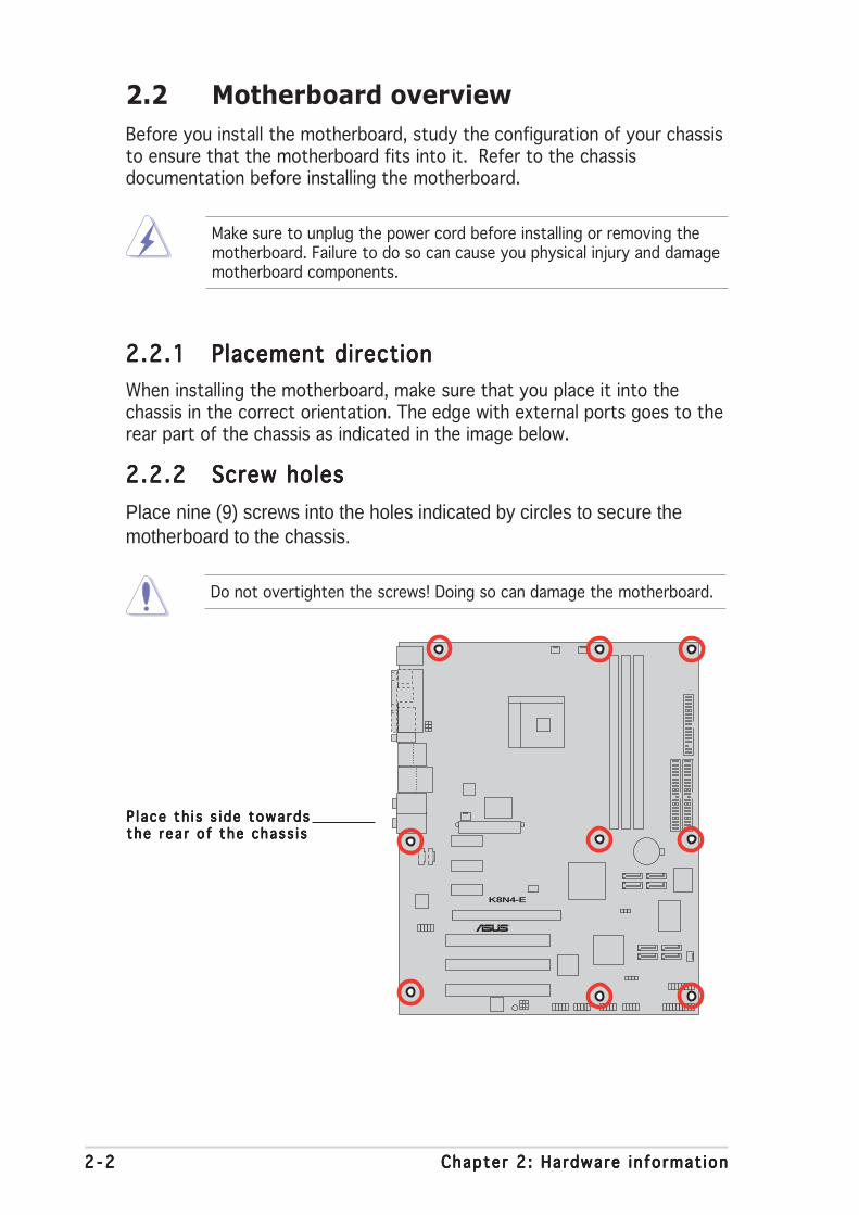
2.2 Motherboard overview
Before you install the motherboard, study the configuration of your chassisto ensure that the motherboard fits into it. Refer to the chassisdocumentation before installing the motherboard.
Make sure to unplug the power cord before installing or removing themotherboard. Failure to do so can cause you physical injury and damagemotherboard components.
Do not overtighten the screws! Doing so can damage the motherboard.
2.2.12.2.12.2.12.2.12.2.1 Placement directionPlacement directionPlacement directionPlacement directionPlacement direction
When installing the motherboard, make sure that you place it into thechassis in the correct orientation. The edge with external ports goes to therear part of the chassis as indicated in the image below.
2.2.22.2.22.2.22.2.22.2.2 Screw holesScrew holesScrew holesScrew holesScrew holes
Place nine (9) screws into the holes indicated by circles to secure themotherboard to the chassis.
P l ace th i s s i de towa rdsP l ace th i s s i de towa rdsP l ace th i s s i de towa rdsP l ace th i s s i de towa rdsP l ace th i s s i de towa rdsthe r ea r o f the chass i sthe r ea r o f the chass i sthe r ea r o f the chass i sthe r ea r o f the chass i sthe r ea r o f the chass i s
ASUS K8N4-E De luxeASUS K8N4-E De luxeASUS K8N4-E De luxeASUS K8N4-E De luxeASUS K8N4-E De luxe 2 - 32 - 32 - 32 - 32 - 3
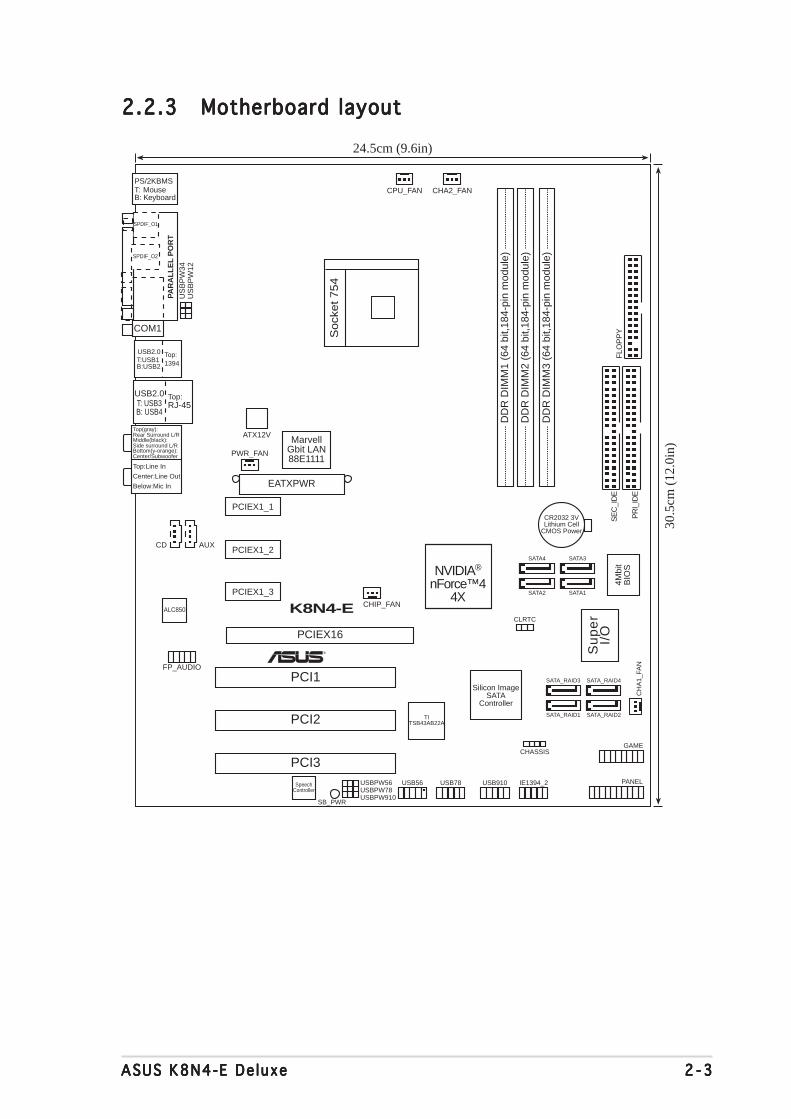
2.2.32.2.32.2.32.2.32.2.3 Motherboard layoutMotherboard layoutMotherboard layoutMotherboard layoutMotherboard layout
PANEL
K8N4-E
®
CR2032 3VLithium Cell
CMOS Power
CD AUX
Su
pe
rI/
O4M
bit
BIO
S
FP_AUDIO
ALC850
USB2.0T: USB3B: USB4
Top:RJ-45
GAME
ATX12V
CHASSIS
PR
I_ID
E
SE
C_I
DE
EATXPWR
1394Top:
T:USB1B:USB2
USB2.0
NVIDIA®
nForce™44X
MarvellGbit LAN88E1111
SB_PWR
CH
A1_
FAN
US
BP
W12
US
BP
W34
24.5cm (9.6in)
30.5
cm (
12.0
in)
PS/2KBMST: MouseB: Keyboard
DD
R D
IMM
1 (6
4 bi
t,184
-pin
mod
ule)
DD
R D
IMM
2 (6
4 bi
t,184
-pin
mod
ule)
DD
R D
IMM
3 (6
4 bi
t,184
-pin
mod
ule)
PCIEX16
PCI1
PCI2
PCI3USB56
SATA4
CPU_FAN
PWR_FAN
So
cke
t 7
54
SATA2
SATA3
SATA1
CLRTC
Below:Mic In
Center:Line Out
Top:Line In
FLO
PP
Y
Bottom(y-orange):Center/Subwoofer
Middle(black):Side surround L/R
Top(gray):Rear Surround L/R
SpeechController
PAR
AL
LE
L P
OR
T
COM1
SPDIF_O1
SPDIF_O2
Silicon ImageSATA
Controller
USBPW78USBPW910
PCIEX1_1
CHA2_FAN
PCIEX1_2
PCIEX1_3
USBPW56 USB78 USB910 IE1394_2
SATA_RAID3
SATA_RAID1
SATA_RAID4
SATA_RAID2
CHIP_FAN
TITSB43AB22A

2 - 42 - 42 - 42 - 42 - 4 Chapter 2 : Hardware in format ionChapter 2 : Hardware in format ionChapter 2 : Hardware in format ionChapter 2 : Hardware in format ionChapter 2 : Hardware in format ion
2.2.42.2.42.2.42.2.42.2.4 Layout ContentsLayout ContentsLayout ContentsLayout ContentsLayout Contents
S l o t sS l o t sS l o t sS l o t sS l o t s P a g eP a g eP a g eP a g eP a g e
1. DDR DIMM slots 2-8
2. PCI slots 2-15
3. PCI Express slots 2-15
Jumpe r sJ umpe r sJ umpe r sJ umpe r sJ umpe r s P a g eP a g eP a g eP a g eP a g e
1. Clear RTC RAM (3-pin CLRTC1) 2-16
2. USB device wake-up (3-pin USBPW12, USBPW34, USBPW56, 2-17
USBPW78, USBPW910)
Rea r pane l connec to r sRea r pane l connec to r sRea r pane l connec to r sRea r pane l connec to r sRea r pane l connec to r s P a g eP a g eP a g eP a g eP a g e
1. PS/2 mouse port 2-18
2. Parallel port 2-18
3. IEEE 1394a port 2-18
4. LAN (RJ-45) port 2-18
5. Rear Speaker Out port 2-18
6. Side Speaker Out port 2-18
7. Line In port 2-18
8. Line Out port 2-18
9. Microphone port 2-19
10. Center/Subwoofer port 2-19
11. USB 2.0 ports 3 and 4 2-19
12. USB 2.0 ports 1 and 2 2-19
13. Serial (COM1) port 2-19
14. Optical S/PDIF Out port 2-19
15. Coaxial S/PDIF Out port 2-19
16. PS/2 keyboard port 2-19

ASUS K8N4-E De luxeASUS K8N4-E De luxeASUS K8N4-E De luxeASUS K8N4-E De luxeASUS K8N4-E De luxe 2 - 52 - 52 - 52 - 52 - 5
In te rna l connec to r sI n te rna l connec to r sI n te rna l connec to r sI n te rna l connec to r sI n te rna l connec to r s P a g eP a g eP a g eP a g eP a g e
1. Floppy disk drive connector (34-1 pin FLOPPY) 2-20
2. IDE connectors (40-1 pin PRI_IDE, SEC_IDE) 2-21
3. Serial ATA connectors (7-pin SATA1 [black], SATA2 [black], 2-22SATA3 [black], SATA4 [black])
4. Serial ATA RAID connectors (7-pin SATA_RAID1 [red], 2-23 SATA_RAID2 [red], SATA_RAID3 [red], SATA_RAID4 [red])
5. CPU fan connector (3-pin CPU_FAN) 2-24
6. Chassis fan connectors (3-pin CHA1_FAN, 3-pin CHA2_FAN) 2-24
7. Chipset fan connector (3-pin CHIP_FAN) 2-24
8. Power fan connector (3-pin PWR_FAN) 2-24
9. USB connectors (10-1 pin USB56, USB78, USB910) 2-25
10. ATX power connectors (24-pin EATXPWR, 4-pin ATX12V) 2-26
11. Internal audio connectors (4-pin CD, AUX) 2-27
12. GAME/MIDI port connector (16-1 pin GAME) 2-27
13. Chassis intrusion connector (4-1 pin CHASSIS) 2-28
14. IEEE 1394a connector (10-1 pin IE1394_2) 2-28
15. Front panel audio connector (10-1 pin 2 x 5-pin FP_AUDIO) 2-29
16. System panel connector (20-pin PANEL) 2-30- System Power LED (Green 3-pin PLED)- Hard Disk activity (Red 2-pin IDE_LED)- System warning speaker (Orange 4-pin SPEAKER)- Power/Soft-off button(Yellow 2-pin PWRSW)- Reset switch (Blue 2-pin RESET)

2 - 62 - 62 - 62 - 62 - 6 Chapter 2 : Hardware in format ionChapter 2 : Hardware in format ionChapter 2 : Hardware in format ionChapter 2 : Hardware in format ionChapter 2 : Hardware in format ion
Installing the CPUInstalling the CPUInstalling the CPUInstalling the CPUInstalling the CPU
To install a CPU:
1. Locate the 754-pin ZIF socket on the motherboard.
2.3 Central Processing Unit (CPU)
The motherboard comes with a surface mount754-pin Zero Insertion Force (ZIF) socketdesigned for the AMD Athlon™ 64/AMDSempron™ processor.
Take note of the marked corner (with goldtriangle) on the CPU. This mark should matcha specific corner on the socket to ensurecorrect installation.
Incorrect installation of the CPU into the socket may bend the pins andseverely damage the CPU!
Go l d t r i a ng l eGo l d t r i a ng l eGo l d t r i a ng l eGo l d t r i a ng l eGo l d t r i a ng l e
K8N4-E
®
K8N4-E DELUXE Socket 754
USB 2.0 connectors
Gold Arrow

ASUS K8N4-E De luxeASUS K8N4-E De luxeASUS K8N4-E De luxeASUS K8N4-E De luxeASUS K8N4-E De luxe 2 - 72 - 72 - 72 - 72 - 7
2. Unlock the socket by pressingthe lever sideways, then lift it upto a 90°-100° angle.
S o c k e tS o c k e tS o c k e tS o c k e tS o c k e tl e v e rl e v e rl e v e rl e v e rl e v e r
Make sure that the socketlever is lifted up to 90°-100°angle; otherwise the CPU doesnot fit in completely.
3. Position the CPU above thesocket such that the CPU cornerwith the gold triangle matchesthe socket corner with a smalltriangle.
4. Carefully insert the CPU into thesocket until it fits in place.
5. When the CPU is in place, pushdown the socket lever to securethe CPU. The lever clicks on theside tab to indicate that it islocked.
6. Install a CPU heatsink and fanfollowing the instructions thatcame with the heatsink package.
7. Connect the CPU fan cable to theCPU_FAN connector on themotherboard.
G o l dG o l dG o l dG o l dG o l dt r i a ng l et r i a ng l et r i a ng l et r i a ng l et r i a ng l e

2 - 82 - 82 - 82 - 82 - 8 Chapter 2 : Hardware in format ionChapter 2 : Hardware in format ionChapter 2 : Hardware in format ionChapter 2 : Hardware in format ionChapter 2 : Hardware in format ion
2.4 System memory
2.4.12.4.12.4.12.4.12.4.1 OverviewOverviewOverviewOverviewOverview
The motherboard comes with three 184-pin Double Data Rate (DDR) DualInline Memory Modules (DIMM) sockets.
The following figure illustrates the location of the sockets:
2.4.22.4.22.4.22.4.22.4.2 Memory ConfigurationsMemory ConfigurationsMemory ConfigurationsMemory ConfigurationsMemory Configurations
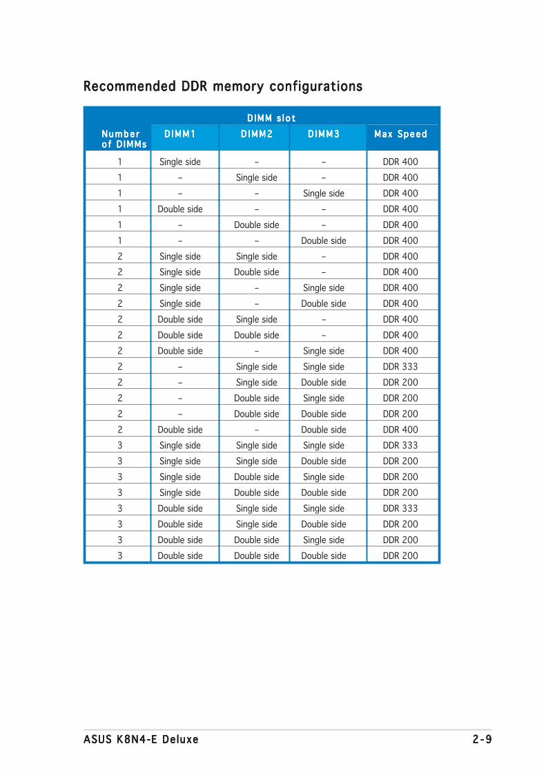
You may install 256 MB, 512 MB, and 1 GB unbuffered non-ECC DDR DIMMsinto the DIMM sockets using the memory configurations in this section.
• Installing DDR DIMMs other than the recommended configurationsmay cause memory sizing error or system boot failure. Use any ofthe recommended configurations on the next page.
• Always install DIMMs with the same CAS latency. For optimumcompatibility, we recommend that you obtain memory modules fromthe same vendor.
• Due to chipset resource allocation, the system may detect less than3 GB system memory when you installed three 1 GB DDR memorymodules.
• This motherboard does not support memory modules made up of128 Mb chips or double sided x16 memory modules.
K8N4-E
®
K8N4-E DELUXE184-pin DDR DIMM sockets
80 P
ins
104
Pin
sD
IMM
1
DIM
M2
DIM
M3
ASUS K8N4-E De luxeASUS K8N4-E De luxeASUS K8N4-E De luxeASUS K8N4-E De luxeASUS K8N4-E De luxe 2 - 92 - 92 - 92 - 92 - 9
Recommended DDR memory configurationsRecommended DDR memory configurationsRecommended DDR memory configurationsRecommended DDR memory configurationsRecommended DDR memory configurations
D IMM s l o tD IMM s l o tD IMM s l o tD IMM s l o tD IMM s l o t
N u m b e rN u m b e rN u m b e rN u m b e rN u m b e r D I M M 1D I M M 1D I M M 1D I M M 1D I M M 1 D I M M 2D I M M 2D I M M 2D I M M 2D I M M 2 D I M M 3D I M M 3D I M M 3D I M M 3D I M M 3 Max SpeedMax SpeedMax SpeedMax SpeedMax Speedo f D IMMso f D IMMso f D IMMso f D IMMso f D IMMs
1 Single side – – DDR 400
1 – Single side – DDR 400
1 – – Single side DDR 400
1 Double side – – DDR 400
1 – Double side – DDR 400
1 – – Double side DDR 400
2 Single side Single side – DDR 400
2 Single side Double side – DDR 400
2 Single side – Single side DDR 400
2 Single side – Double side DDR 400
2 Double side Single side – DDR 400
2 Double side Double side – DDR 400
2 Double side – Single side DDR 400
2 – Single side Single side DDR 333
2 – Single side Double side DDR 200
2 – Double side Single side DDR 200
2 – Double side Double side DDR 200
2 Double side – Double side DDR 400
3 Single side Single side Single side DDR 333
3 Single side Single side Double side DDR 200
3 Single side Double side Single side DDR 200
3 Single side Double side Double side DDR 200
3 Double side Single side Single side DDR 333
3 Double side Single side Double side DDR 200
3 Double side Double side Single side DDR 200
3 Double side Double side Double side DDR 200
2 -102 -102 -102 -102 -10 Chapter 2 : Hardware in format ionChapter 2 : Hardware in format ionChapter 2 : Hardware in format ionChapter 2 : Hardware in format ionChapter 2 : Hardware in format ion
DDR (400 MHz) Qualified Vendors ListDDR (400 MHz) Qualified Vendors ListDDR (400 MHz) Qualified Vendors ListDDR (400 MHz) Qualified Vendors ListDDR (400 MHz) Qualified Vendors List
S i z eS i z eS i z eS i z eS i z e V e n d o rV e n d o rV e n d o rV e n d o rV e n d o r M o d e lM o d e lM o d e lM o d e lM o d e l B r a n dB r a n dB r a n dB r a n dB r a n d S i d e / s *S i d e / s *S i d e / s *S i d e / s *S i d e / s * C o m p o n e n tC o m p o n e n tC o m p o n e n tC o m p o n e n tC o m p o n e n t C LC LC LC LC L
256MB KINGSTON KVR400X64C3A/256 Hynix SS HY5DU56822BT-D43 –
512MB KINGSTON KVR400X64C3A/512 Hynix DS HY5DU56822BT-D43 –
256MB KINGSTON KVR400X72C3A/256 Mosel SS V58C2256804SAT5(ECC) –
512MB KINGSTON KVR400X72C3A/512 Mosel DS V58C2256804SAT5(ECC) –
256MB KINGSTON KVR400X64C3A/256 Infineon SS HYB25D256800BT-5B –
512MB KINGSTON KVR400X64C3A/512 Infineon DS HYB25D256809BT-5B –
256MB KINGSTON KVR400X64C3A/256 KINGSTON SS D3208DL2T-5 –
512MB KINGSTON KHX3200A/512 – DS – 3
1024MB KINGSTON KVR400X64C3A/1G – DS HYB25D512800BE-5B 3
1024MB KINGSTON KHX3200ULK2/1G – DS – 2
256MB SAMSUNG M381L3223ETM-CCC SAMSUNG SS K4H560838E-TCCC(ECC) 3ECC
512MB SAMSUNG M381L6423ETM-CCC SAMSUNG DS K4H560838E-TCCC(ECC) –
256MB SAMSUNG M368L3223ETM-CCC SAMSUNG SS K4H560838E-TCCC –
256MB SAMSUNG M368L3223FTN-CCC SAMSUNG SS K4H560838F-TCCC 4
512MB SAMSUNG M368L6423FTN-CCC SAMSUNG DS K4H560838F-TCCC 4
512MB SAMSUNG M368L6523BTM-CCC SAMSUNG SS K4H510838B-TCCC 4
256MB MICRON MT8VDDT3264AG-40BCB MICRON SS MT46V32M8TG-5BC –
512MB MICRON MT16VDDT6464AG-40BCB MICRON DS MT46V32M8TG-5BC –
256MB Infineon HYS64D32300HU-5-C Infineon SS HYB25D256800CE-5C 3
512MB Infineon HYS64D64320HU-5-C Infineon DS HYB25D256800CE-5C –
256MB CORSAIR CMX256A-3200C2PT Winbond SS W942508BH-5 2
512MB CORSAIR VS512MB400 VALUE seLecT DS VS32M8-5 2.5
512MB CORSAIR CMX512-3200C2 – DS – 3
1024MB CORSAIR TWINX2048-3200C2 – DS – –
256MB Hynix HYMD232645D8J-D43 Hynix SS HY5DU56822DT-D43 3
512MB Hynix HYMD264646D8J-D43 Hynix DS HY5DU56822DT-D43 3
256MB TwinMOS M2G9I08AIATT9F081AADT TwinMOS SS TMD7608F8E50D 2.5
512MB TwinMOS M2G9J16AJATT9F081AADT TwinMOS DS TMD7608F8E50D 2.5
256MB TwinMOS M2G9I08A8ATT9F081AADT TwinMOS SS TMD7608F8E50D 2.5
512MB TwinMOS M2G9J16A8ATT9F081AADT TwinMOS DS TMD7608F8E50D 2.5
256MB Transcend TS32MLD64V4F3 SAMSUNG SS K4H560838F-TCCC 3
512MB Transcend TS64MLD64V4F3 SAMSUNG DS K4H560838F-TCCC 3
1024MB Transcend TS128MLD64V4J SAMSUNG DS K4H510838B-TCCC 3
256MB Apacer 77.10636.33G Infineon SS HYB25D256800CE-5C 3
512MB Apacer 77.10736.33G Infineon DS HYB25D256800CE-5C 3
256MB Apacer 77.10639.60G ProMOS SS V58C2256804SCT5B 2.5
512MB Apacer 77.10739.60G ProMOS DS V58C2256804SCT5B 2.5
256MB A DATA MDOSS6F3G31Y0K1E0Z SAMSUNG SS K4H560838E-TCCC 3
512MB A DATA MDOSS6F3H41Y0N1E0Z SAMSUNG DS K4H560838F-TCCC 3
256MB A DATA MDOHY6F3G31Y0N1E0Z Hynix SS HY5DU56822CT-D43 3
512MB A DATA MDOHY6F3H41Y0N1E0Z Hynix DS HY5DU56822CT-D43 3
256MB A DATA MDOAD5F3G31Y0D1E02 – SS ADD8608A8A-5B 2.5
512MB A DATA MDOAD5F3H41Y0D1E02 – DS ADD8608A8A-5B 2.5
256MB Winbond W9425GCDB-5 Winbond SS W942508CH-5 3
512MB Winbond W9451GCDB-5 Winbond DS W942508CH-5 –
256MB PSC AL5D8B53T-5B1K PSC SS A2S56D30BTP 2.5
D I M M s u p p o r tD I M M s u p p o r tD I M M s u p p o r tD I M M s u p p o r tD I M M s u p p o r t

ASUS K8N4-E De luxeASUS K8N4-E De luxeASUS K8N4-E De luxeASUS K8N4-E De luxeASUS K8N4-E De luxe 2 -112 -112 -112 -112 -11
DDR (400 MHz) Qualified Vendors ListDDR (400 MHz) Qualified Vendors ListDDR (400 MHz) Qualified Vendors ListDDR (400 MHz) Qualified Vendors ListDDR (400 MHz) Qualified Vendors List
D I M M s u p p o r t D I M M s u p p o r t D I M M s u p p o r t D I M M s u p p o r t D I M M s u p p o r t
Legend:Legend:Legend:Legend:Legend:
S SS SS SS SS S - Single-sided
D SD SD SD SD S - Double-sided
C LC LC LC LC L - CAS Latency
Visit the ASUS website (www.asus.com) for the latest DDR 400 QualifiedVendors List.
S i z eS i z eS i z eS i z eS i z e V e n d o rV e n d o rV e n d o rV e n d o rV e n d o r M o d e lM o d e lM o d e lM o d e lM o d e l B r a n dB r a n dB r a n dB r a n dB r a n d S i d e / s *S i d e / s *S i d e / s *S i d e / s *S i d e / s * C o m p o n e n tC o m p o n e n tC o m p o n e n tC o m p o n e n tC o m p o n e n t C LC LC LC LC L
512MB PSC AL6D8B53T-5B1K PSC DS A2S56D30BTP 2.5
256MB KINGMAX MPXB62D-38KT3R – SS KDL388P4LA-50 –
512MB KINGMAX MPXC22D-38KT3R – DS KDL388P4LA-50 –
256MB NANYA NT256D64S88C0G-5T – SS NT5DS32M8CT-5T 3
512MB NANYA NT512D64S8HC0G-5T – DS NT5DS32M8CT-5T 3
256MB BRAIN POWER B6U808-256M-SAM-400 SAMSUNG SS K4H560838D-TCC4 –
512MB BRAIN POWER B6U808-512M-SAM-400 SAMSUNG DS K4H560838D-TCC4 –
256MB CENTURY DXV6S8SSCCE3K27E SAMSUNG SS K4H560838E-TCCC –
512MB CENTURY DXV2S8SSCCE3K27E SAMSUNG DS K4H560838E-TCCC –
256MB CENTURY DXV6S8EL5BM3T27C – SS DD2508AMTA –
512MB CENTURY DXV2S8EL5BM3T27C – DS DD2508AMTA –
256MB elixir M2U25664DS88C3G-5T – SS N2DS25680CT-5T –
512MB elixir M2U51264DS8HC1G-5T – DS N2DS25680CT-5T –
256MB Kreton – VT SS VT3225804T-5 –
512MB Kreton – VT DS VT3225804T-5 –
256MB Veritech VT400FMV/2561103 VT SS VT56DD32M8PC-5 3
512MB Veritech VT400FMV/5121003 VT DS VT56DD32M8PC-5 3
256MB Pmi MD44256VIT3208GMHA01 MOSEL SS V58C2256804SAT5B 2.5
512MB Pmi MD44512VIT3208GATA03 MOSEL DS V58C2256804SAT5B 2.5
256MB ProMOS V826632K24SCTG-D0 – SS V58C2256804SCT5B 2.5
512MB ProMOS V826664K24SCTG-D0 – DS V58C2256804SCT5B 2.5
256MB Deutron AL5D8C53T-5B1T PSC SS A2S56D30CTP 2.5
512MB Deutron AL6D8C53T-5B1T PSC DS A2S56D30CTP 2.5
256MB GEIL GL5123200DC – SS GL3LC32G88TG-35 –
512MB GEIL GL1GB3200DC – DS GL3LC32G88TG-35 –
256MB GEIL GLX2563200UP – SS GL3LC32G88TG-5A –
256MB GEIL GD3200-512DC – SS WLCSP Package –
256MB crucial BL3264Z402.8TG Ballistix SS – 2
512MB crucial BL6464Z402.16TG Ballistix DS – 2
256MB Novax 96M425653CE-40TB6 CEON SS C2S56D30TP-5 2.5
512MB Novax 96M451253CE-40TB6 CEON DS C2S56D30TP-5 2.5
2 -122 -122 -122 -122 -12 Chapter 2 : Hardware in format ionChapter 2 : Hardware in format ionChapter 2 : Hardware in format ionChapter 2 : Hardware in format ionChapter 2 : Hardware in format ion
2.4.42.4.42.4.42.4.42.4.4 Removing a DDR DIMMRemoving a DDR DIMMRemoving a DDR DIMMRemoving a DDR DIMMRemoving a DDR DIMM
To remove a DIMM:
1. Simultaneously press theretaining clips outward to unlockthe DIMM.
2. Remove the DIMM from the socket.
Support the DIMM lightly with your fingers when pressing the retainingclips. The DIMM might get damaged when it flips out with extra force.
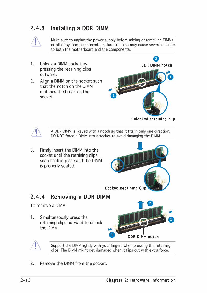
2.4.32.4.32.4.32.4.32.4.3 Installing a DDR DIMMInstalling a DDR DIMMInstalling a DDR DIMMInstalling a DDR DIMMInstalling a DDR DIMM
3. Firmly insert the DIMM into thesocket until the retaining clipssnap back in place and the DIMMis properly seated.
1. Unlock a DIMM socket bypressing the retaining clipsoutward.
2. Align a DIMM on the socket suchthat the notch on the DIMMmatches the break on thesocket.
Locked Re ta i n i ng C l i pLocked Re ta i n i ng C l i pLocked Re ta i n i ng C l i pLocked Re ta i n i ng C l i pLocked Re ta i n i ng C l i p
Make sure to unplug the power supply before adding or removing DIMMsor other system components. Failure to do so may cause severe damageto both the motherboard and the components.
A DDR DIMM is keyed with a notch so that it fits in only one direction.DO NOT force a DIMM into a socket to avoid damaging the DIMM.
Un locked re ta i n i ng c l i pUn locked re ta i n i ng c l i pUn locked re ta i n i ng c l i pUn locked re ta i n i ng c l i pUn locked re ta i n i ng c l i p
DDR D IMM no tchDDR D IMM no tchDDR D IMM no tchDDR D IMM no tchDDR D IMM no tch
1
2
1
DDR D IMM no tchDDR D IMM no tchDDR D IMM no tchDDR D IMM no tchDDR D IMM no tch1
2
1

ASUS K8N4-E De luxeASUS K8N4-E De luxeASUS K8N4-E De luxeASUS K8N4-E De luxeASUS K8N4-E De luxe 2 -132 -132 -132 -132 -13
2.5 Expansion slots
In the future, you may need to install expansion cards. The followingsub-sections describe the slots and the expansion cards that they support.
2.5.12.5.12.5.12.5.12.5.1 Installing an expansion cardInstalling an expansion cardInstalling an expansion cardInstalling an expansion cardInstalling an expansion card
To install an expansion card:
1. Before installing the expansion card, read the documentation thatcame with it and make the necessary hardware settings for the card.
2. Remove the system unit cover (if your motherboard is alreadyinstalled in a chassis).
3. Remove the bracket opposite the slot that you intend to use. Keepthe screw for later use.
4. Align the card connector with the slot and press firmly until the card iscompletely seated on the slot.
5. Secure the card to the chassis with the screw you removed earlier.
6. Replace the system cover.
2.5.22.5.22.5.22.5.22.5.2 Configuring an expansion cardConfiguring an expansion cardConfiguring an expansion cardConfiguring an expansion cardConfiguring an expansion card
After installing the expansion card, configure it by adjusting the softwaresettings.
1. Turn on the system and change the necessary BIOS settings, if any.See Chapter 4 for information on BIOS setup.
2. Assign an IRQ to the card. Refer to the tables on the next page.
3. Install the software drivers for the expansion card.
Make sure to unplug the power cord before adding or removingexpansion cards. Failure to do so may cause you physical injury anddamage motherboard components.

2 -142 -142 -142 -142 -14 Chapter 2 : Hardware in format ionChapter 2 : Hardware in format ionChapter 2 : Hardware in format ionChapter 2 : Hardware in format ionChapter 2 : Hardware in format ion
2.5.32.5.32.5.32.5.32.5.3 Interrupt assignmentsInterrupt assignmentsInterrupt assignmentsInterrupt assignmentsInterrupt assignments
Standard interrupt assignmentsStandard interrupt assignmentsStandard interrupt assignmentsStandard interrupt assignmentsStandard interrupt assignments
I R QI R QI R QI R QI R Q P r i o r i t yP r i o r i t yP r i o r i t yP r i o r i t yP r i o r i t y S tanda rd Func t i onStanda rd Func t i onStanda rd Func t i onStanda rd Func t i onStanda rd Func t i on
0 1 System Timer1 2 Keyboard Controller2 — Programmable Interrupt3* 11 IRQ holder for PCI steering4* 12 Communications Port (COM1)5* 13 IRQ holder for PCI steering6 14 Floppy Disk Controller7* 15 Printer Port (LPT1)8 3 System CMOS/Real Time Clock9* 4 IRQ holder for PCI steering10* 5 IRQ holder for PCI steering11* 6 IRQ holder for PCI steering12* 7 PS/2 Compatible Mouse Port13 8 Numeric Data Processor14* 9 Primary IDE Channel15* 10 Secondary IDE Channel
* These I RQs a re usua l l y ava i l ab l e fo r I SA o r PC I dev i ces .* These I RQs a re usua l l y ava i l ab l e fo r I SA o r PC I dev i ces .* These I RQs a re usua l l y ava i l ab l e fo r I SA o r PC I dev i ces .* These I RQs a re usua l l y ava i l ab l e fo r I SA o r PC I dev i ces .* These I RQs a re usua l l y ava i l ab l e fo r I SA o r PC I dev i ces .
IRQ assignments for this motherboardIRQ assignments for this motherboardIRQ assignments for this motherboardIRQ assignments for this motherboardIRQ assignments for this motherboard
AAAAA BBBBB CCCCC DDDDD EEEEE FFFFF GGGGG HHHHH
PCI slot 1 shared — — — — — — —PCI slot 2 — shared — — — — — —PCI slot 3 — — shared — — — — —Onboard USB 2.0 controller shared — — — — — — —Onboard LAN1 shared — — — — — — —Onboard PCI SATA RAID (SI) — — — shared — — — —Onboard 1394a shared — — — — — — —
When using PCI cards on shared slots, ensure that the drivers support“Share IRQ” or that the cards do not need IRQ assignments. Otherwise,conflicts will arise between the two PCI groups, making the systemunstable and the card inoperable.

ASUS K8N4-E De luxeASUS K8N4-E De luxeASUS K8N4-E De luxeASUS K8N4-E De luxeASUS K8N4-E De luxe 2 -152 -152 -152 -152 -15
2.5.42.5.42.5.42.5.42.5.4 PCI slotsPCI slotsPCI slotsPCI slotsPCI slots
The PCI slots support cards such as aLAN card, SCSI card, USB card, andother cards that comply with PCIspecifications. The figure shows aLAN card installed on a PCI slot.
2.5.52.5.52.5.52.5.52.5.5 PCI Express x16 slotPCI Express x16 slotPCI Express x16 slotPCI Express x16 slotPCI Express x16 slot
This motherboard supports PCIExpress x16 graphic cards thatcomply with the PCI Expressspecifications. The following figureshows a graphics card installed onthe PCI Express x16 slot.
2.5.62.5.62.5.62.5.62.5.6 PCI Express x1 slotPCI Express x1 slotPCI Express x1 slotPCI Express x1 slotPCI Express x1 slot
This motherboard supports PCIExpress x1 network cards, SCSI cards,and other cards that comply with thePCI Express specifications. Thefollowing figure shows a network cardinstalled on the PCI Express x1 slot.

2 -162 -162 -162 -162 -16 Chapter 2 : Hardware in format ionChapter 2 : Hardware in format ionChapter 2 : Hardware in format ionChapter 2 : Hardware in format ionChapter 2 : Hardware in format ion
2.6 Jumpers
Except when clearing the RTC RAM, never remove the cap on CLRTCjumper default position. Removing the cap will cause system boot failure!
You do not need to clear the RTC when the system hangs due tooverclocking. For system failure due to overclocking, use the C.P.R. (CPUParameter Recall) feature. Shut down and reboot the system so the BIOScan automatically reset parameter settings to default values.
21 32K8N4-E
®
K8N4-E DELUXE Clear RTC RAM
CLRTC
Normal Clear CMOS(Default)
1 .1 .1 .1 .1 . C lear RTC RAM (CLRTC)Clear RTC RAM (CLRTC)Clear RTC RAM (CLRTC)Clear RTC RAM (CLRTC)Clear RTC RAM (CLRTC)
This jumper allows you to clear the Real Time Clock (RTC) RAM inCMOS. You can clear the CMOS memory of date, time, and systemsetup parameters by erasing the CMOS RTC RAM data. The onboardbutton cell battery powers the RAM data in CMOS, which includesystem setup information such as system passwords.
To erase the RTC RAM:
1. Turn OFF the computer and unplug the power cord.
2. Remove the onboard battery.
3. Move the jumper cap from pins 1-2 (default) to pins 2-3. Keep thecap on pins 2-3 for about 5~10 seconds, then move the cap back topins 1-2.
4. Re-install the battery.
5. Plug the power cord and turn ON the computer.
6. Hold down the <Del> key during the boot process and enter BIOSsetup to re-enter data.

ASUS K8N4-E De luxeASUS K8N4-E De luxeASUS K8N4-E De luxeASUS K8N4-E De luxeASUS K8N4-E De luxe 2 -172 -172 -172 -172 -17
2 .2 .2 .2 .2 . USB device wake-up (3-pin USBPW12, USBPW34,USB device wake-up (3-pin USBPW12, USBPW34,USB device wake-up (3-pin USBPW12, USBPW34,USB device wake-up (3-pin USBPW12, USBPW34,USB device wake-up (3-pin USBPW12, USBPW34,USBPW56, USBPW78, USBPW910)USBPW56, USBPW78, USBPW910)USBPW56, USBPW78, USBPW910)USBPW56, USBPW78, USBPW910)USBPW56, USBPW78, USBPW910)
Set these jumpers to +5V to wake up the computer from S1 sleepmode (CPU stopped, DRAM refreshed, system running in low powermode) using the connected USB devices. Set to +5VSB to wake upfrom S3 and S4 sleep modes (no power to CPU, DRAM in slow refresh,power supply in reduced power mode).
The USBPWR12 and USBPWR34 jumpers are for the rear USB ports.The USBPWR56, USBPWR78, and USBPW910 jumpers are for theinternal USB connectors that you can connect to additional USB ports.
• The USB device wake-up feature requires a power supply that canprovide 500mA on the +5VSB lead for each USB port; otherwise,the system would not power up.
• The total current consumed must NOT exceed the power supplycapability (+5VSB) whether under normal condition or in sleep mode.
K8N4-E
®
322
1
3221
K8N4-E DELUXE USB device wake up+5V
(Default)+5VSB
USBPW56USBPW78
+5V(Default)
+5VSB
USBPW12USBPW34
USBPW910

2 -182 -182 -182 -182 -18 Chapter 2 : Hardware in format ionChapter 2 : Hardware in format ionChapter 2 : Hardware in format ionChapter 2 : Hardware in format ionChapter 2 : Hardware in format ion
2.7 Connectors
2.7.12.7.12.7.12.7.12.7.1 Rear panel connectorsRear panel connectorsRear panel connectorsRear panel connectorsRear panel connectors
1 .1 .1 .1 .1 . PS/2 mouse port (green).PS/2 mouse port (green).PS/2 mouse port (green).PS/2 mouse port (green).PS/2 mouse port (green). This port is for a PS/2 mouse.
2 .2 .2 .2 .2 . Para l le l port .Para l le l port .Para l le l port .Para l le l port .Para l le l port . This 25-pin port connects a parallel printer, a scanner,or other devices.
3 .3 .3 .3 .3 . IEEE 1394a port .IEEE 1394a port .IEEE 1394a port .IEEE 1394a port .IEEE 1394a port . This 6-pin IEEE 1394a port provides high-speedconnectivity for audio/video devices, storage peripherals, PCs, orportable devices.
4 .4 .4 .4 .4 . LAN (RJ-45) port .LAN (RJ-45) port .LAN (RJ-45) port .LAN (RJ-45) port .LAN (RJ-45) port . This port allows Gigabit connection to a LocalArea Network (LAN) through a network hub. Refer to the table belowfor the LAN port LED indications.
5 .5 .5 .5 .5 . Rear Speaker Out port (gray).Rear Speaker Out port (gray).Rear Speaker Out port (gray).Rear Speaker Out port (gray).Rear Speaker Out port (gray). This port connects the rearspeakers on a 4-channel, 6-channel, or 8-channel audio configuration.
6 .6 .6 .6 .6 . S ide Speaker Out port (b lack).S ide Speaker Out port (b lack).S ide Speaker Out port (b lack).S ide Speaker Out port (b lack).S ide Speaker Out port (b lack). This port connects the sidespeakers in an 8-channel audio configuration.
7 .7 .7 .7 .7 . L ine In port ( l ight b lue).L ine In port ( l ight b lue).L ine In port ( l ight b lue).L ine In port ( l ight b lue).L ine In port ( l ight b lue). This port connects a tape, CD, DVDplayer, or other audio sources.
8 .8 .8 .8 .8 . L ine Out port ( l ime).L ine Out port ( l ime).L ine Out port ( l ime).L ine Out port ( l ime).L ine Out port ( l ime). This port connects a headphone or aspeaker. In 4-channel, 6-channel, and 8-channel configuration, thefunction of this port becomes Front Speaker Out.
LAN port LED indicationsLAN port LED indicationsLAN port LED indicationsLAN port LED indicationsLAN port LED indications
ACT/L INK LEDACT/L INK LEDACT/L INK LEDACT/L INK LEDACT/L INK LED SPEED LED SPEED LED SPEED LED SPEED LED SPEED LED
S t a t u sS t a t u sS t a t u sS t a t u sS t a t u s Desc r i p t i onDesc r i p t i onDesc r i p t i onDesc r i p t i onDesc r i p t i on S t a t u sS t a t u sS t a t u sS t a t u sS t a t u s Desc r i p t i onDesc r i p t i onDesc r i p t i onDesc r i p t i onDesc r i p t i on
OFF No link OFF 10Mbps connection
GREEN Linked ORANGE 100Mbps connection
BLINKING Acting GREEN 1Gbps connectionLAN po r tLAN po r tLAN po r tLAN po r tLAN po r t
ACT/L INKACT/L INKACT/L INKACT/L INKACT/L INKL E DL E DL E DL E DL E D
S P E E DS P E E DS P E E DS P E E DS P E E DL E DL E DL E DL E DL E D
1
16 11
2 4
1315
7
8
9
5 6
1014
3
12

ASUS K8N4-E De luxeASUS K8N4-E De luxeASUS K8N4-E De luxeASUS K8N4-E De luxeASUS K8N4-E De luxe 2 -192 -192 -192 -192 -19
11 .11 .11 .11 .11 . USB 2.0 ports 3 and 4.USB 2.0 ports 3 and 4.USB 2.0 ports 3 and 4.USB 2.0 ports 3 and 4.USB 2.0 ports 3 and 4. These two 4-pin Universal Serial Bus(USB) ports are available for connecting USB 2.0 devices.
12 .12 .12 .12 .12 . USB 2.0 ports 1 and 2.USB 2.0 ports 1 and 2.USB 2.0 ports 1 and 2.USB 2.0 ports 1 and 2.USB 2.0 ports 1 and 2. These two 4-pin Universal Serial Bus(USB) ports are available for connecting USB 2.0 devices.
13 .13 .13 .13 .13 . Ser ia l portSer ia l portSer ia l portSer ia l portSer ia l port. This 9-pin COM1 port is for pointing devices or otherserial devices.
14 .14 .14 .14 .14 . Opt ica l S/PDIF Out port . Opt ica l S/PDIF Out port . Opt ica l S/PDIF Out port . Opt ica l S/PDIF Out port . Opt ica l S/PDIF Out port . This port connects an external audiooutput device via an optical S/PDIF cable.
15 .15 .15 .15 .15 . Coaxia l S/PDIF Out port . Coaxia l S/PDIF Out port . Coaxia l S/PDIF Out port . Coaxia l S/PDIF Out port . Coaxia l S/PDIF Out port . This port connects an external audiooutput device via a coaxial S/PDIF cable.
16 .16 .16 .16 .16 . PS/2 keyboard port (purple) .PS/2 keyboard port (purple) .PS/2 keyboard port (purple) .PS/2 keyboard port (purple) .PS/2 keyboard port (purple) . This port is for a PS/2 keyboard.
Audio 2, 4, 6, or 8-channel configurationAudio 2, 4, 6, or 8-channel configurationAudio 2, 4, 6, or 8-channel configurationAudio 2, 4, 6, or 8-channel configurationAudio 2, 4, 6, or 8-channel configuration
Light Blue Line In Line In Line In Line In
Lime Line Out Front Speaker Out Front Speaker Out Front Speaker Out
Pink Mic In Mic In Mic In Mic In
Gray - Rear Speaker Out Rear Speaker Out Rear Speaker Out
Black - - - Side Speaker Out
Yellow Orange - - Center/Subwoofer Center/Subwoofer
P o r tP o r tP o r tP o r tP o r t H e a d s e tH e a d s e tH e a d s e tH e a d s e tH e a d s e t 4 - channe l4 - channe l4 - channe l4 - channe l4 - channe l 6 - channe l6 - channe l6 - channe l6 - channe l6 - channe l 8 - channe l8 - channe l8 - channe l8 - channe l8 - channe l2-channel2-channel2-channel2-channel2-channel
Refer to the audio configuration table for the function of the audio portsin 2, 4, 6, or 8-channel configuration.
9 .9 .9 .9 .9 . Microphone port (p ink). Microphone port (p ink). Microphone port (p ink). Microphone port (p ink). Microphone port (p ink). This port connects a microphone.
10 .10 .10 .10 .10 . Center/Subwoofer port (yel low orange).Center/Subwoofer port (yel low orange).Center/Subwoofer port (yel low orange).Center/Subwoofer port (yel low orange).Center/Subwoofer port (yel low orange). This port connectsthe center/subwoofer speakers.

2 -202 -202 -202 -202 -20 Chapter 2 : Hardware in format ionChapter 2 : Hardware in format ionChapter 2 : Hardware in format ionChapter 2 : Hardware in format ionChapter 2 : Hardware in format ion
2.7.22.7.22.7.22.7.22.7.2 Internal connectorsInternal connectorsInternal connectorsInternal connectorsInternal connectors
1 .1 .1 .1 .1 . F loppy disk dr ive connector (34-1 pin FLOPPY)Floppy disk dr ive connector (34-1 pin FLOPPY)Floppy disk dr ive connector (34-1 pin FLOPPY)Floppy disk dr ive connector (34-1 pin FLOPPY)Floppy disk dr ive connector (34-1 pin FLOPPY)
This connector is for the provided floppy disk drive (FDD) signal cable.Insert one end of the cable to this connector, then connect the otherend to the signal connector at the back of the floppy disk drive.
Pin 5 on the connector is removed to prevent incorrect cable connectionwhen using an FDD cable with a covered Pin 5.
K8N4-E
®
K8N4-E DELUXE Floppy disk drive connector
NOTE: Orient the red markings onthe floppy ribbon cable to PIN 1.
FLOPPY
PIN 1
ASUS K8N4-E De luxeASUS K8N4-E De luxeASUS K8N4-E De luxeASUS K8N4-E De luxeASUS K8N4-E De luxe 2 -212 -212 -212 -212 -21
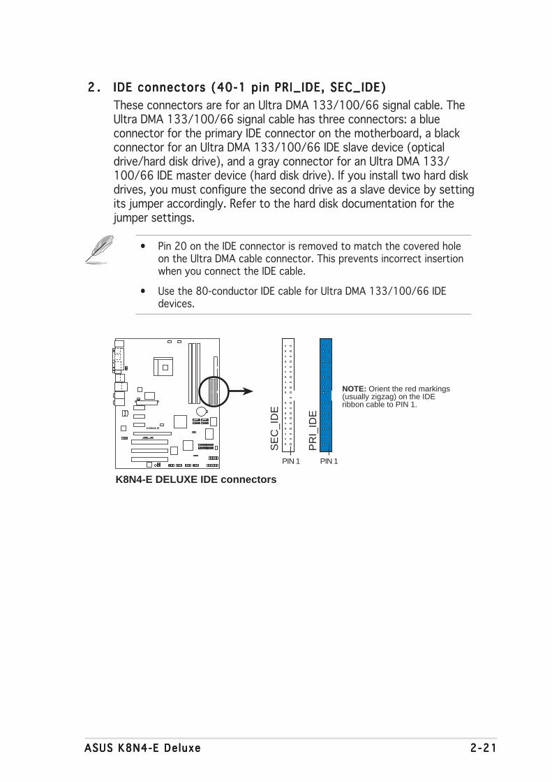
2 .2 .2 .2 .2 . IDE connectors (40-1 pin PRI_IDE, SEC_IDE)IDE connectors (40-1 pin PRI_IDE, SEC_IDE)IDE connectors (40-1 pin PRI_IDE, SEC_IDE)IDE connectors (40-1 pin PRI_IDE, SEC_IDE)IDE connectors (40-1 pin PRI_IDE, SEC_IDE)
These connectors are for an Ultra DMA 133/100/66 signal cable. TheUltra DMA 133/100/66 signal cable has three connectors: a blueconnector for the primary IDE connector on the motherboard, a blackconnector for an Ultra DMA 133/100/66 IDE slave device (opticaldrive/hard disk drive), and a gray connector for an Ultra DMA 133/100/66 IDE master device (hard disk drive). If you install two hard diskdrives, you must configure the second drive as a slave device by settingits jumper accordingly. Refer to the hard disk documentation for thejumper settings.
• Pin 20 on the IDE connector is removed to match the covered holeon the Ultra DMA cable connector. This prevents incorrect insertionwhen you connect the IDE cable.
• Use the 80-conductor IDE cable for Ultra DMA 133/100/66 IDEdevices.
K8N4-E
®
K8N4-E DELUXE IDE connectors
SE
C_I
DE
PR
I_ID
E
PIN 1PIN 1
NOTE: Orient the red markings(usually zigzag) on the IDEribbon cable to PIN 1.

2 -222 -222 -222 -222 -22 Chapter 2 : Hardware in format ionChapter 2 : Hardware in format ionChapter 2 : Hardware in format ionChapter 2 : Hardware in format ionChapter 2 : Hardware in format ion
3 .3 .3 .3 .3 . Ser ia l ATA connectorsSer ia l ATA connectorsSer ia l ATA connectorsSer ia l ATA connectorsSer ia l ATA connectors(7-pin SATA1 [black], SATA2 [black], SATA3 [black],(7-pin SATA1 [black], SATA2 [black], SATA3 [black],(7-pin SATA1 [black], SATA2 [black], SATA3 [black],(7-pin SATA1 [black], SATA2 [black], SATA3 [black],(7-pin SATA1 [black], SATA2 [black], SATA3 [black],SATA4 [b lack])SATA4 [b lack])SATA4 [b lack])SATA4 [b lack])SATA4 [b lack])
Supported by the NVIDIA® nForce4-4X chipset, these connectors arefor the Serial ATA signal cables for Serial ATA hard disk drives thatallow up to 3Gb/s of data transfer rate.
If you installed Serial ATA hard disk drives, you can create RAID 0,RAID 1, RAID 1+0, or JBOD configuration that spans across the ParallelATA drives. Refer to Chapter 5 for details on how to set up RAIDconfigurations.
Important notes on Ser ia l ATAImportant notes on Ser ia l ATAImportant notes on Ser ia l ATAImportant notes on Ser ia l ATAImportant notes on Ser ia l ATA
••••• The actual data transfer rate depends on the speed of Serial ATAhard disks installed.
••••• See the Appendix for instructions on how to install the Serial ATAextension module.
These connectors are set to SATA SATA SATA SATA SATA by default. In SATA mode, you canconnect Serial ATA boot or data hard disk drives to these connectors. Ifyou intend to create a Serial ATA RAID set using these connectors,enable the RA ID RA ID RA ID RA ID RA ID function of each port from the NVRA IDNVRA IDNVRA IDNVRA IDNVRA IDconf igurat ion conf igurat ion conf igurat ion conf igurat ion conf igurat ion sub-item in the BIOS. See section “4.4.3 Onboarddevice configuration” for details.
K8N4-E
®
K8N4-E DELUXE SATA connectors
SATA2
GN
DR
SAT
A_T
XP
2R
SAT
A_T
XN
2G
ND
RS
ATA
_RX
P2
RS
ATA
_RX
N2
GN
D
SATA1
GN
DR
SAT
A_T
XP
1R
SAT
A_T
XN
1G
ND
RS
ATA
_RX
P1
RS
ATA
_RX
N1
GN
DSATA4
GN
DR
SAT
A_T
XP
4R
SAT
A_T
XN
4G
ND
RS
ATA
_RX
P4
RS
ATA
_RX
N4
GN
D
SATA3
GN
DR
SAT
A_T
XP
3R
SAT
A_T
XN
3G
ND
RS
ATA
_RX
P3
RS
ATA
_RX
N3
GN
D

ASUS K8N4-E De luxeASUS K8N4-E De luxeASUS K8N4-E De luxeASUS K8N4-E De luxeASUS K8N4-E De luxe 2 -232 -232 -232 -232 -23
4 .4 .4 .4 .4 . Ser ia l ATA RAID connectors (7-pin SATA_RAID1 [red],Ser ia l ATA RAID connectors (7-pin SATA_RAID1 [red],Ser ia l ATA RAID connectors (7-pin SATA_RAID1 [red],Ser ia l ATA RAID connectors (7-pin SATA_RAID1 [red],Ser ia l ATA RAID connectors (7-pin SATA_RAID1 [red],SATA_RAID2 [red], SATA_RAID3 [red], SATA_RAID4SATA_RAID2 [red], SATA_RAID3 [red], SATA_RAID4SATA_RAID2 [red], SATA_RAID3 [red], SATA_RAID4SATA_RAID2 [red], SATA_RAID3 [red], SATA_RAID4SATA_RAID2 [red], SATA_RAID3 [red], SATA_RAID4[red])[ red])[ red])[ red])[ red])
These connectors are for Serial ATA signal cables. These connectorssupport up to four Serial ATA hard disk drives that you can configureas a disk array through the onboard SATA RAID controller. Refer toChapter 5 for details on how to set up Serial ATA RAID configurations.
These connectors are set to RA ID ModeRA ID ModeRA ID ModeRA ID ModeRA ID Mode by default. If you want toconnect Serial ATA boot/data hard disk drives to these connectors, setthe S i l i con SATA Contro l le rS i l i con SATA Contro l le rS i l i con SATA Contro l le rS i l i con SATA Contro l le rS i l i con SATA Contro l le r item in the BIOS to [Disabled]. Seesection “4.4.3 Onboard Device Configuration” for details.
• Before creating a RAID set using Serial ATA hard disks, make surethat you have connected the Serial ATA signal cable and installedSerial ATA hard disk drives; otherwise, you cannot enter the SiliconImage RAID utility and SATA BIOS setup during POST.
• You can only create RAID 5 configuration using the SATALink™ SATARAID Management software. See Chapter 5 for details. The RAID 5feature is not Windows® Hardware Quality Labs (WHQL)-certified.
K8N4-E
®
K8N4-E DELUXE SATA RAID Connectors
GN
DR
SAT
A_T
XP
2R
SAT
A_T
XN
2G
ND
RS
ATA
_RX
P2
RS
ATA
_RX
N2
GN
D
GN
DR
SAT
A_T
XP
1R
SAT
A_T
XN
1G
ND
RS
ATA
_RX
P1
RS
ATA
_RX
N1
GN
D
SATA_RAID2SATA_RAID1
GN
DR
SAT
A_T
XP
4R
SAT
A_T
XN
4G
ND
RS
ATA
_RX
P4
RS
ATA
_RX
N4
GN
D
GN
DR
SAT
A_T
XP
3R
SAT
A_T
XN
3G
ND
RS
ATA
_RX
P3
RS
ATA
_RX
N3
GN
DSATA_RAID4SATA_RAID3

2 -242 -242 -242 -242 -24 Chapter 2 : Hardware in format ionChapter 2 : Hardware in format ionChapter 2 : Hardware in format ionChapter 2 : Hardware in format ionChapter 2 : Hardware in format ion
5 .5 .5 .5 .5 . CPU, Chass is and Power fan connectorsCPU, Chass is and Power fan connectorsCPU, Chass is and Power fan connectorsCPU, Chass is and Power fan connectorsCPU, Chass is and Power fan connectors(3-pin CPU_FAN, 3-pin CHA1_FAN, 3-pin CHA2_FAN,(3-pin CPU_FAN, 3-pin CHA1_FAN, 3-pin CHA2_FAN,(3-pin CPU_FAN, 3-pin CHA1_FAN, 3-pin CHA2_FAN,(3-pin CPU_FAN, 3-pin CHA1_FAN, 3-pin CHA2_FAN,(3-pin CPU_FAN, 3-pin CHA1_FAN, 3-pin CHA2_FAN,3-pin CHIP_FAN, 3-p in PWR_FAN)3-pin CHIP_FAN, 3-p in PWR_FAN)3-pin CHIP_FAN, 3-p in PWR_FAN)3-pin CHIP_FAN, 3-p in PWR_FAN)3-pin CHIP_FAN, 3-p in PWR_FAN)
The fan connectors support cooling fans of 350 mA ~ 2000 mA (24 Wmax.) or a total of 1 A ~ 3.48 A (41.76 W max.) at +12 V. Connectthe fan cables to the fan connectors on the motherboard, making surethat the black wire of each cable matches the ground pin of theconnector.
Do not forget to connect the fan cables to the fan connectors.Insufficient air flow inside the system may damage the motherboardcomponents. These are not jumpers! DO NOT place jumper caps on thefan connectors.
K8N4-E
®
K8N4-E DELUXE Fan connectors
CPU_FAN
CHA1_FAN
GN
D
Rot
atio
n+
12V
PWR_FAN
GN
D
Rot
atio
n+
12V GND
Rotation+12V
GN
D
Rot
atio
n+
12V
GN
D
Rot
atio
n+
12V
CHA2_FAN
CHIP_FAN

ASUS K8N4-E De luxeASUS K8N4-E De luxeASUS K8N4-E De luxeASUS K8N4-E De luxeASUS K8N4-E De luxe 2 -252 -252 -252 -252 -25
Never connect a 1394 cab le1394 cab le1394 cab le1394 cab le1394 cab le to the USB connectors. Doing so willdamage the motherboard!
6 .6 .6 .6 .6 . USB connectors (10-1 pin USB56, USB78, USB910)USB connectors (10-1 pin USB56, USB78, USB910)USB connectors (10-1 pin USB56, USB78, USB910)USB connectors (10-1 pin USB56, USB78, USB910)USB connectors (10-1 pin USB56, USB78, USB910)
These connectors are for USB 2.0 ports. Connect the USB/GAMEmodule cable to any of these connectors, then install the module to aslot opening at the back of the system chassis. These USB connectorscomply with USB 2.0 specification that supports up to 480 Mbpsconnection speed.
K8N4-E
®
K8N4-E DELUXEUSB 2.0 connectors
USB56
US
B+
5VU
SB
_P6-
US
B_P
6+G
ND
NC
US
B+
5VU
SB
_P5-
US
B_P
5+G
ND
1USB78
US
B+
5VU
SB
_P8-
US
B_P
8+G
ND
NC
US
B+
5VU
SB
_P7-
US
B_P
7+G
ND
1USB910
US
B+
5VU
SB
_P10
-U
SB
_P10
+G
ND
NC
US
B+
5VU
SB
_P9-
US
B_P
9+G
ND
1

2 -262 -262 -262 -262 -26 Chapter 2 : Hardware in format ionChapter 2 : Hardware in format ionChapter 2 : Hardware in format ionChapter 2 : Hardware in format ionChapter 2 : Hardware in format ion
7 .7 .7 .7 .7 . ATX power connectors (24-pin EATXPWR, 4-pin ATX12V)ATX power connectors (24-pin EATXPWR, 4-pin ATX12V)ATX power connectors (24-pin EATXPWR, 4-pin ATX12V)ATX power connectors (24-pin EATXPWR, 4-pin ATX12V)ATX power connectors (24-pin EATXPWR, 4-pin ATX12V)
These connectors are for an ATX power supply. The plugs from thepower supply are designed to fit these connectors in only oneorientation. Find the proper orientation and push down firmly until theconnectors completely fit.
• We recommend that you use an ATX 12 V Specification2.0-compliant power supply unit (PSU) with a minimum of 350 Wpower rating. This PSU type has 24-pin and 4-pin power plugs.
• If you intend to use a PSU with 20-pin and 4-pin power plugs, makesure that the 20-pin power plug can provide at least 15A on +12Vand that the PSU has a minimum power rating of 350 W. The systemmay become unstable or may not boot up if the power isinadequate.
• Do not forget to connect the 4-pin ATX +12 V power plug;otherwise, the system will not boot up.
• We recommend that you use a PSU with higher power output whenconfiguring a system with more power-consuming devices. Thesystem may become unstable or may not boot up if the power isinadequate.
• The ATX 12 V Specification 2.0-compliant PSU passed themotherboard power requirement test with the followingconfiguration:
CPU : Intel® Pentium® 4 3.6 GHzMemory : 512 MB DDR (x 4)Graphics card : PCI Express x16 Nvidia EN5900Parallel ATA devices : IDE hard disk drive (x 2)Serial ATA device : SATA hard disk driveOptical drives : CD-ROM (x 2)SCSI devices : SCSI card and SCSI hard disk drive
• You must install a PSU with a higher power rating if you intend toinstall additional devices.

ASUS K8N4-E De luxeASUS K8N4-E De luxeASUS K8N4-E De luxeASUS K8N4-E De luxeASUS K8N4-E De luxe 2 -272 -272 -272 -272 -27
8 .8 .8 .8 .8 . Internal audio connectors (4-pin CD, AUX)Internal audio connectors (4-pin CD, AUX)Internal audio connectors (4-pin CD, AUX)Internal audio connectors (4-pin CD, AUX)Internal audio connectors (4-pin CD, AUX)
These connectors allow you to receive stereo audio input from soundsources such as a CD-ROM, TV tuner, or MPEG card.
9 .9 .9 .9 .9 . GAME/MIDI port connector (16-1 pin GAME)GAME/MIDI port connector (16-1 pin GAME)GAME/MIDI port connector (16-1 pin GAME)GAME/MIDI port connector (16-1 pin GAME)GAME/MIDI port connector (16-1 pin GAME)
This connector is for a GAME/MIDI port. Connect the USB/GAMEmodule cable to this connector, then install the module to a slotopening at the back of the system chassis. The GAME/MIDI portconnects a joystick or game pad for playing games, and MIDI devicesfor playing or editing audio files.
K8N4-E
®
K8N4-E DELUXE Internal audio connectors
AUX (White)
Right Audio Channel
Left Audio Channel
Ground
CD (Black)
K8N4-E
®
K8N4-E DELUXE Game connectorGAME
+5V
+5V
J2B
1J2
CX
MID
I_O
UT
J2C
YJ2
B2
MID
I_IN
J1B
1J1
CX
GN
DG
ND
J1C
YJ1
B2
+5V

2 -282 -282 -282 -282 -28 Chapter 2 : Hardware in format ionChapter 2 : Hardware in format ionChapter 2 : Hardware in format ionChapter 2 : Hardware in format ionChapter 2 : Hardware in format ion
10 .10 .10 .10 .10 . Chass is intrus ion connector (4-1 pin CHASSIS)Chass is intrus ion connector (4-1 pin CHASSIS)Chass is intrus ion connector (4-1 pin CHASSIS)Chass is intrus ion connector (4-1 pin CHASSIS)Chass is intrus ion connector (4-1 pin CHASSIS)
This connector is for a chassis-mounted intrusion detection sensor orswitch. Connect one end of the chassis intrusion sensor or switchcable to this connector. The chassis intrusion sensor or switch sends ahigh-level signal to this connector when a chassis component isremoved or replaced. The signal is then generated as a chassisintrusion event.
By default, the pins labeled “Chassis Signal” and “Ground” are shortedwith a jumper cap. Remove the jumper caps only when you intend touse the chassis intrusion detection feature.
NEVER connect a USB cab le USB cab le USB cab le USB cab le USB cab le to the IEEE 1394a connector. Doing sowill damage the motherboard!
11 .11 .11 .11 .11 . IEEE 1394a connector (10-1 pin IE1394_2)IEEE 1394a connector (10-1 pin IE1394_2)IEEE 1394a connector (10-1 pin IE1394_2)IEEE 1394a connector (10-1 pin IE1394_2)IEEE 1394a connector (10-1 pin IE1394_2)
This connector is for an IEEE 1394a port. Connect the IEEE 1394amodule cable to this connector, then install the module to a slotopening at the back of the system chassis.
K8N4-E
®
K8N4-E DELUXE Chassis intrusion connector
CHASSIS+
5VS
B_M
B
Cha
ssis
Sig
nal
GN
D
(Default)
K8N4-E
®
K8N4-E DELUXE IEEE-1394 connector
IE1394_21
TP
A0-
GN
DT
PB
0-+
12V
GN
D
TP
A0+
GN
DT
PB
0++
12V

ASUS K8N4-E De luxeASUS K8N4-E De luxeASUS K8N4-E De luxeASUS K8N4-E De luxeASUS K8N4-E De luxe 2 -292 -292 -292 -292 -29
12 .12 .12 .12 .12 . FFFFFront panel audio connector (10-1 pin 2 x 5-pin FP_AUDIO)ront panel audio connector (10-1 pin 2 x 5-pin FP_AUDIO)ront panel audio connector (10-1 pin 2 x 5-pin FP_AUDIO)ront panel audio connector (10-1 pin 2 x 5-pin FP_AUDIO)ront panel audio connector (10-1 pin 2 x 5-pin FP_AUDIO)
This connector is for a chassis-mounted front panel audio I/O modulethat supports either HD Audio or legacy AC ‘97 audio standard.Connect one end of the front panel audio I/O module cable to thisconnector.
We recommend that you connect a high-definition front panel audiomodule to this connector to avail of the motherboard’s high-definitionaudio capability.
K8N4-E
®
K8N4-E DELUXE Front panel audio connector
FP_AUDIO
BLI
NE
_OU
T_L
MIC
2
Line
out
_R
Line
out
_L
BLI
NE
_OU
T_R
NC
MIC
PW
R+
5VA
AG
ND

2 -302 -302 -302 -302 -30 Chapter 2 : Hardware in format ionChapter 2 : Hardware in format ionChapter 2 : Hardware in format ionChapter 2 : Hardware in format ionChapter 2 : Hardware in format ion
13 .13 .13 .13 .13 . System panel connector (20-pin PANEL)System panel connector (20-pin PANEL)System panel connector (20-pin PANEL)System panel connector (20-pin PANEL)System panel connector (20-pin PANEL)
This connector supports several chassis-mounted functions.
The sytem panel connector is color-coded for easy connection. Refer tothe connector description below for details.
• System power LED (Green 3-pin PLED)System power LED (Green 3-pin PLED)System power LED (Green 3-pin PLED)System power LED (Green 3-pin PLED)System power LED (Green 3-pin PLED)This 3-pin connector is for the system power LED. Connect thechassis power LED cable to this connector. The system power LEDlights up when you turn on the system power, and blinks when thesystem is in sleep mode.
• Hard d isk dr ive act iv ity (Red 2-pin IDE_LED)Hard d isk dr ive act iv ity (Red 2-pin IDE_LED)Hard d isk dr ive act iv ity (Red 2-pin IDE_LED)Hard d isk dr ive act iv ity (Red 2-pin IDE_LED)Hard d isk dr ive act iv ity (Red 2-pin IDE_LED)This 2-pin connector is for the HDD Activity LED. Connect the HDDActivity LED cable to this connector. The IDE LED lights up or flasheswhen data is read from or written to the HDD.
• System warning speaker (Orange 4-pin SPEAKER)System warning speaker (Orange 4-pin SPEAKER)System warning speaker (Orange 4-pin SPEAKER)System warning speaker (Orange 4-pin SPEAKER)System warning speaker (Orange 4-pin SPEAKER)This 4-pin connector is for the chassis-mounted system warningspeaker. The speaker allows you to hear system beeps and warnings.
• Power/Soft-off button (Yel low 2-pin PWRSW)Power/Soft-off button (Yel low 2-pin PWRSW)Power/Soft-off button (Yel low 2-pin PWRSW)Power/Soft-off button (Yel low 2-pin PWRSW)Power/Soft-off button (Yel low 2-pin PWRSW)This connector is for the system power button. Pressing the powerbutton turns the system ON or puts the system in SLEEP or SOFT-OFFmode depending on the BIOS settings. Pressing the power switch formore than four seconds while the system is ON turns the system OFF.
• Reset button (Blue 2-pin RESET)Reset button (Blue 2-pin RESET)Reset button (Blue 2-pin RESET)Reset button (Blue 2-pin RESET)Reset button (Blue 2-pin RESET)This 2-pin connector is for the chassis-mounted reset button forsystem reboot without turning off the system power.
K8N4-E
®
K8N4-E DELUXE System panel connector* Requires an ATX power supply.
PANEL
PLE
D-
PW
R+
5V Spe
aker
PLED
Gro
und
RESET
Gro
und
Res
etG
roun
dG
roun
d
PLE
D+
IDE
_LE
D-
IDE
_LE
D+
IDE_LED
SPEAKER
PWRSW

3Powering up
This chapter describes the power upsequence, the vocal POST messages,and ways of shutting down thesystem.
ASUS K8N4-E De luxeASUS K8N4-E De luxeASUS K8N4-E De luxeASUS K8N4-E De luxeASUS K8N4-E De luxe
Chapter summary 33.1 Starting up for the first time ................................................ 3-1
3.2 Powering off the computer .................................................. 3-2
3.3 ASUS POST Reporter™ .......................................................... 3-3
3.3.1 Vocal POST messages ............................................ 3-3
3.3.2 Winbond Voice Editor ............................................. 3-5

ASUS K8N4-E De luxeASUS K8N4-E De luxeASUS K8N4-E De luxeASUS K8N4-E De luxeASUS K8N4-E De luxe 3 - 13 - 13 - 13 - 13 - 1
3.1 Starting up for the first time
1. After making all the connections, replace the system case cover.
2. Be sure that all switches are off.
3. Connect the power cord to the power connector at the back of thesystem chassis.
4. Connect the power cord to a power outlet that is equipped with asurge protector.
5. Turn on the devices in the following order:
a. Monitor
b. External SCSI devices (starting with the last device on the chain)
c. System power
6. After applying power, the system power LED on the system frontpanel case lights up. For systems withATX power supplies, the systemLED lights up when you press the ATX power button. If your monitorcomplies with “green” standards or if it has a “power standby”feature, the monitor LED may light up or switch between orange andgreen after the system LED turns on.
The system then runs the power-on self tests or POST. While thetests are running, the BIOS beeps (see BIOS beep codes table below)or additional messages appear on the screen. If you do not seeanything within 30 seconds from the time you turned on the power,the system may have failed a power-on test. Check the jumpersettings and connections or call your retailer for assistance.
7. At power on, hold down the <Delete> key to enter the BIOS Setup.Follow the instructions in Chapter 4.

3 - 23 - 23 - 23 - 23 - 2 Chapter 3 : Power ing upChapter 3 : Power ing upChapter 3 : Power ing upChapter 3 : Power ing upChapter 3 : Power ing up
3.2 Powering off the computer
3.2.13.2.13.2.13.2.13.2.1 Using the OS shut down functionUsing the OS shut down functionUsing the OS shut down functionUsing the OS shut down functionUsing the OS shut down function
If you are using Windows® 2000:
1. Click the Start Start Start Start Start button then click Shut Down. . .Shut Down. . .Shut Down. . .Shut Down. . .Shut Down. . .
2. Make sure that the Shut DownShut DownShut DownShut DownShut Down option button is selected, then clickthe OK OK OK OK OK button to shut down the computer.
3. The power supply should turn off after Windows® shuts down.
If you are using Windows® XP:
1. Click the Start Start Start Start Start button then select Turn Off Computer .Turn Off Computer .Turn Off Computer .Turn Off Computer .Turn Off Computer .
2. Click the Turn Off Turn Off Turn Off Turn Off Turn Off button to shut down the computer.
3. The power supply should turn off after Windows® shuts down.
3.2.23.2.23.2.23.2.23.2.2 Using the dual function power switchUsing the dual function power switchUsing the dual function power switchUsing the dual function power switchUsing the dual function power switch
While the system is ON, pressing the power switch for less than fourseconds puts the system to sleep mode or to soft-off mode, depending onthe BIOS setting. Pressing the power switch for more than four secondslets the system enter the soft-off mode regardless of the BIOS setting.Refer to section “4.5 Power Menu” in Chapter 4 for details.

ASUS K8N4-E De luxeASUS K8N4-E De luxeASUS K8N4-E De luxeASUS K8N4-E De luxeASUS K8N4-E De luxe 3 - 33 - 33 - 33 - 33 - 3
3.3 ASUS POST Reporter™
This motherboard includes the Winbond speech controller to support aspecial feature called the ASUS POST Reporter™. This feature gives youvocal POST messages and alerts you of system events and boot status. Incase of a boot failure, you will hear the specific cause of the problem.
These POST messages are customizable using the Winbond Voice Editorsoftware that came with your package. You can record your own messagesto replace the default messages.
3.3.13.3.13.3.13.3.13.3.1 Vocal POST messagesVocal POST messagesVocal POST messagesVocal POST messagesVocal POST messages
Following is a list of the default POST messages and the correspondingactions you can take:
POST MessagePOST MessagePOST MessagePOST MessagePOST Message A c t i o nA c t i o nA c t i o nA c t i o nA c t i o n
No CPU installed • Install a supported processor intothe CPU socket. See section “2.3Central Processing Unit (CPU)” forsupported processors.
System failed CPU test • Check the CPU if properly installed.• Call ASUS technical support for
assistance. See the “ASUS contactinformation” on the inside front coverof this manual.
System failed memory test • Install supported DDR DIMMs into thesockets.
• Check if the DIMMs on the DIMM socketsare properly installed.
• Make sure that your DIMMs are notdefective.
• Refer to section “2.4 System memory”for instructions on installing a DIMM.
System failed VGA test • Install a PCI VGA card into one of thePCI slots, or a 1.5V AGP card into theAGP slot.
• Make sure that your VGA/AGP card isnot defective.
System failed due to CPU • Check your CPU settings in the BIOSoverclocking and set only to the recommended
No keyboard detected • Check if your keyboard is properlyconnected to the purple PS/2connector on the rear panel.
• See section “2.7.1 Rear panelconnectors” for the location of theconnector.
No IDE hard disk detected • Make sure you have connected an IDEhard disk drive to one of the IDEconnectors on the motherboard.

3 - 43 - 43 - 43 - 43 - 4 Chapter 3 : Power ing upChapter 3 : Power ing upChapter 3 : Power ing upChapter 3 : Power ing upChapter 3 : Power ing up
You can disable the ASUS POST Reporter™ in the BIOS setup. See section“4.4.7 Speech configuration.”
POST MessagePOST MessagePOST MessagePOST MessagePOST Message A c t i o nA c t i o nA c t i o nA c t i o nA c t i o n
CPU temperature too high • Check if the CPU fan is workingproperly.
CPU fan failed • Check the CPU fan and make sureit turns on after you apply powerto the system.
• Make sure that your CPU fansupports the fan speed detectionfunction.
CPU voltage out of range • Check your power supply andmake sure it is not defective.
• Call ASUS technical support forassistance. See the “ASUS contactinformation” on the inside frontcover of this manual.
System completed Power-On Self Test • No action required
Computer now booting from operating • No action requiredsystem

ASUS K8N4-E De luxeASUS K8N4-E De luxeASUS K8N4-E De luxeASUS K8N4-E De luxeASUS K8N4-E De luxe 3 - 53 - 53 - 53 - 53 - 5
3.3.23.3.23.3.23.3.23.3.2 Winbond Voice EditorWinbond Voice EditorWinbond Voice EditorWinbond Voice EditorWinbond Voice Editor
The Winbond Voice Editor software allows you to customize the vocalPOST messages. Install the software from the utilities menu of the supportCD. See section “5.2.3 Utilities menu” for details.
To avoid conflicts, do not run the Winbond Voice Editor while runningthe ASUS PC Probe.
Follow these steps to use the Winbond Voice Editor.
Launching the programLaunching the programLaunching the programLaunching the programLaunching the program
Launch the program either from the Winbond Voice Editor icon on yourdesktop, or from the Windows Start menu, select Programs->WinbondPrograms->WinbondPrograms->WinbondPrograms->WinbondPrograms->WinbondVoice Editor->Voice EditorVoice Editor->Voice EditorVoice Editor->Voice EditorVoice Editor->Voice EditorVoice Editor->Voice Editor.
The Winbond Voice Editor screen appears.
Playing the default wave fi lesPlaying the default wave fi lesPlaying the default wave fi lesPlaying the default wave fi lesPlaying the default wave fi les
To play the default wave files, simply click on a POST event on the left sideof the screen, then click the Play button.
The default language setting is English.
De fau l t MessagesDe fau l t MessagesDe fau l t MessagesDe fau l t MessagesDe fau l t MessagesPOST Even t sPOST Even t sPOST Even t sPOST Even t sPOST Even t s

3 - 63 - 63 - 63 - 63 - 6 Chapter 3 : Power ing upChapter 3 : Power ing upChapter 3 : Power ing upChapter 3 : Power ing upChapter 3 : Power ing up
For some languages, not all events have a corresponding message dueto file size constraints.
3. Click the Wr i te Wr i te Wr i te Wr i te Wr i te button toupdate the EEPROM.
4. Click Yes Yes Yes Yes Yes on the confirmationwindow that appears.
The next time you boot your computer, the POST messages are announcedin the language that you selected .
1. Click the LoadLoadLoadLoadLoad button. Awindow showing the availablelanguages appears.
2. Select your desired language,then click OpenOpenOpenOpenOpen. The eventmessages for the language youselected appear on the VoiceEditor screen.
Changing the default languageChanging the default languageChanging the default languageChanging the default languageChanging the default language
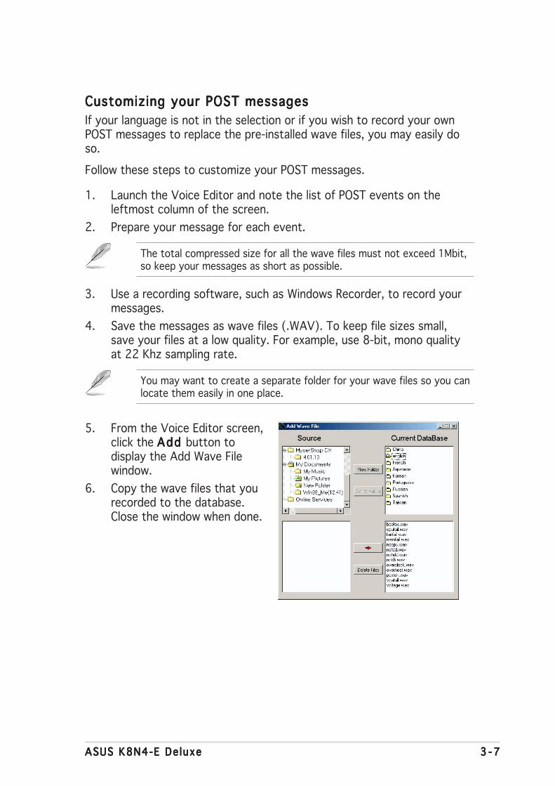
ASUS K8N4-E De luxeASUS K8N4-E De luxeASUS K8N4-E De luxeASUS K8N4-E De luxeASUS K8N4-E De luxe 3 - 73 - 73 - 73 - 73 - 7
You may want to create a separate folder for your wave files so you canlocate them easily in one place.
Customizing your POST messagesCustomizing your POST messagesCustomizing your POST messagesCustomizing your POST messagesCustomizing your POST messages
If your language is not in the selection or if you wish to record your ownPOST messages to replace the pre-installed wave files, you may easily doso.
Follow these steps to customize your POST messages.
1. Launch the Voice Editor and note the list of POST events on theleftmost column of the screen.
2. Prepare your message for each event.
The total compressed size for all the wave files must not exceed 1Mbit,so keep your messages as short as possible.
3. Use a recording software, such as Windows Recorder, to record yourmessages.
4. Save the messages as wave files (.WAV). To keep file sizes small,save your files at a low quality. For example, use 8-bit, mono qualityat 22 Khz sampling rate.
5. From the Voice Editor screen,click the Add Add Add Add Add button todisplay the Add Wave Filewindow.
6. Copy the wave files that yourecorded to the database.Close the window when done.

3 - 83 - 83 - 83 - 83 - 8 Chapter 3 : Power ing upChapter 3 : Power ing upChapter 3 : Power ing upChapter 3 : Power ing upChapter 3 : Power ing up
If you receive an error message telling you that the files exceed the totalallowable size, do one or all of the following.
• Shorten your messages.
• Save the wave files at a lower quality
• Skip seldom-used events like FDD Detection, IDE HDD Detection, etc.
7. Select a POST event on theVoice Editor screen, then clickthe Ed i t Ed i t Ed i t Ed i t Ed i t button. The EventSound Editor window appears.
8. Locate and select your wavefile for the event, then clickon the arrow opposite Voice1.The file you select appears onthe space next to it.
9. Click OK OK OK OK OK to return to theVoice Editor screen.
10. Do steps 7 to 9 for the otherevents.
11. When done, click SaveSaveSaveSaveSave. Awindow appears promptingyou to save yourconfiguration.
12. Type a file name with an . f l h. f l h. f l h. f l h. f l hextension, then click Save.
13. Click the Wr i te Wr i te Wr i te Wr i te Wr i te button tocompress the file and copyinto the EEPROM.
14. Click Yes Yes Yes Yes Yes on the confirmationwindow that appears.

4BIOS setup
This chapter tells how to changethe system settings through the BIOSSetup menus. Detailed descriptionsof the BIOS parameters are alsoprovided.

ASUS K8N4-E De luxeASUS K8N4-E De luxeASUS K8N4-E De luxeASUS K8N4-E De luxeASUS K8N4-E De luxe
Chapter summary 44.1 Managing and updating your BIOS ........................................ 4-1
4.2 BIOS setup program ........................................................... 4-11
4.3 Main menu .......................................................................... 4-14
4.4 Advanced menu .................................................................. 4-19
4.5 Power menu ........................................................................ 4-36
4.6 Boot menu .......................................................................... 4-41
4.7 Exit menu ........................................................................... 4-46

ASUS K8N4-E De luxeASUS K8N4-E De luxeASUS K8N4-E De luxeASUS K8N4-E De luxeASUS K8N4-E De luxe 4 - 14 - 14 - 14 - 14 - 1
4.1 Managing and updating your BIOS
Important notesImportant notesImportant notesImportant notesImportant notes
• Save a copy of the or ig ina l motherboard B IOS f i l eor ig ina l motherboard B IOS f i l eor ig ina l motherboard B IOS f i l eor ig ina l motherboard B IOS f i l eor ig ina l motherboard B IOS f i l e to abootab le f loppy d iskbootab le f loppy d iskbootab le f loppy d iskbootab le f loppy d iskbootab le f loppy d isk in case you need to restore the BIOS inthe future. Copy the original motherboard BIOS using the ASUSUpdate or AFLASH utilities.
• Visit the system builder’s website and download the latest BIOS filefor this motherboard using the ASUS Update utility.
4.1.14.1.14.1.14.1.14.1.1 Creating a bootable floppy diskCreating a bootable floppy diskCreating a bootable floppy diskCreating a bootable floppy diskCreating a bootable floppy disk
1. Do either one of the following to create a bootable floppy disk.
DOS environment
a. Insert a 1.44 MB floppy disk into the drive.
b. At the DOS prompt, type format A:/S then press <Enter>.
Windows® XP environment
a. Insert a 1.44 MB floppy disk to the floppy disk drive.
b. Click Start Start Start Start Start from the Windows® desktop, then select M yM yM yM yM yComputerComputerComputerComputerComputer.
c. Select the 3 1/2 Floppy Drive icon.
d. Click F i l e F i l e F i l e F i l e F i l e from the menu, then select FormatFormatFormatFormatFormat. A Format 3 1/2Format 3 1/2Format 3 1/2Format 3 1/2Format 3 1/2Floppy D iskF loppy D iskF loppy D iskF loppy D iskF loppy D isk window appears.
e. Select Create an MS-DOS startup d isk Create an MS-DOS startup d isk Create an MS-DOS startup d isk Create an MS-DOS startup d isk Create an MS-DOS startup d isk from the formatoptions field, then click Sta r tSta r tSta r tSta r tSta r t.
The following utilities allow you to manage and update the motherboardBasic Input/Output System (BIOS) setup.
1. AwardBIOS F lash Ut i l i ty AwardBIOS F lash Ut i l i ty AwardBIOS F lash Ut i l i ty AwardBIOS F lash Ut i l i ty AwardBIOS F lash Ut i l i ty (Updates the BIOS using a floppy diskduring POST.)
2. ASUS EZ F lash ASUS EZ F lash ASUS EZ F lash ASUS EZ F lash ASUS EZ F lash (Updates the BIOS using a floppy disk during POST.)
3. ASUS CrashFree B IOSASUS CrashFree B IOSASUS CrashFree B IOSASUS CrashFree B IOSASUS CrashFree B IOS Ut i l i tyUt i l i tyUt i l i tyUt i l i tyUt i l i ty (Updates the BIOS using a bootablefloppy disk when the BIOS gets corrupted.)
4. ASUS UpdateASUS UpdateASUS UpdateASUS UpdateASUS Update (Updates the BIOS in Windows® environment.)
Refer to the corresponding section for details on these utilities.

4 - 24 - 24 - 24 - 24 - 2 Chapter 4 : B IOS setupChapter 4 : B IOS setupChapter 4 : B IOS setupChapter 4 : B IOS setupChapter 4 : B IOS setup
4.1.24.1.24.1.24.1.24.1.2 AwardBIOS Flash UtilityAwardBIOS Flash UtilityAwardBIOS Flash UtilityAwardBIOS Flash UtilityAwardBIOS Flash Utility
The Basic Input/Output System (BIOS) can be updated using the built-inFlash Memory Writer utility or using a bootable floppy disk with theexecutable Flash Memory Writer Utility (AWDFLASH.EXE). Follow theseinstructions to update the BIOS using this utility.
Save only the updated BIOS file in the floppy disk to avoid loading awrong BIOS file.
Updating the BIOS fi leUpdating the BIOS fi leUpdating the BIOS fi leUpdating the BIOS fi leUpdating the BIOS fi le
1. Download the latest BIOS file from the system builder’s website. .Rename the file to (BIOS file name on the support CD).BIN and save itto the bootable floppy disk you created earlier.
2. Copy the AwardBIOS Flash Utility (awdflash.exe) from the Softwarefolder of the support CD to the floppy disk with the latest BIOS file.
3. Boot the system in DOS mode using the bootable floppy disk youcreated earlier.
The succeeding screens are for reference only. The actual displays maynot exactly match what you see on your screen.
Windows® 2000 environment
To create a set of boot disks for Windows® 2000:
a. Insert a formatted, high density 1.44 MB floppy disk into the drive.
b. Insert the Windows® 2000 CD to the optical drive.
c. Click Sta r tSta r tSta r tSta r tSta r t, then select R unRunRunRunRun.
d. From the Open field, type
D:\bootdisk\makeboot a:
assuming that D: is your optical drive.
e. Press <Enter>, then follow screen instructions to continue.
2. Copy the original or the latest motherboard BIOS file to the bootablefloppy disk.

ASUS K8N4-E De luxeASUS K8N4-E De luxeASUS K8N4-E De luxeASUS K8N4-E De luxeASUS K8N4-E De luxe 4 - 34 - 34 - 34 - 34 - 3
4. When the A : >A : >A : >A : >A : > appears, replace the bootable floppy disk with thefloppy disk containing the new BIOS file and the Award BIOS FlashUtility.
5. At the prompt, typeawdf lashawdf lashawdf lashawdf lashawdf lash then press<Enter>. The AwardBIOS Flash Utility screenappears.
AwardBIOS Flash Utility for ASUS V1.09(C) Phoenix Technologies Ltd. All Rights Reserved
Message: Please input File Name!
For NF-CK804-K8N4-E-00 DATE: 12/16/2004Flash Type - SST 49LF004A/B /3.3V
File Name to Program:
6. Type the BIOS file namein the F i le Name toF i le Name toF i le Name toF i le Name toF i le Name toProgramProgramProgramProgramProgram field, thenpress <Enter>.
7. The utility prompts you to save the current BIOS file. Press <Y> tosave the current BIOS file to the floppy disk, or <N> to continue.
If you intend to save the current BIOS file, make sure that the floppydisk has enough disk space to save the file. See the next section fordetails on saving the current BIOS file.
AwardBIOS Flash Utility for ASUS V1.09(C) Phoenix Technologies Ltd. All Rights Reserved
For NF-CK804-K8N4-E-00 DATE: 12/16/2004Flash Type - SST 49LF004A/B /3.3V
File Name to Program: 1231A.bin
Message: Do You Want To Save Bios (Y/N)

4 - 44 - 44 - 44 - 44 - 4 Chapter 4 : B IOS setupChapter 4 : B IOS setupChapter 4 : B IOS setupChapter 4 : B IOS setupChapter 4 : B IOS setup
8. The utility verifies theBIOS file in the floppydisk and starts flashingthe BIOS file.
Do not turn off or reset the system during the flashing process!
AwardBIOS Flash Utility for ASUS V1.09(C) Phoenix Technologies Ltd. All Rights Reserved
Warning: Don’t Turn Off Power Or Reset System!
For NF-CK804-K8N4-E-00 DATE: 12/16/2004Flash Type - SST 49LF004A/B /3.3V
File Name to Program: 1231A.bin
Program Flashing Memory - OFE00 OK
Write OK No Update Write Fail123123123
1234567890123456789012345678901123456789012345678901234567890112345678901234567890123456789011234567890123456789012345678901
123123123
123123123
9. The utility displays aF lash ing CompleteF lash ing CompleteF lash ing CompleteF lash ing CompleteF lash ing Completemessage indicating thatyou have successfullyflashed the BIOS file.Remove the floppy diskthen press <F1> torestart the system.
AwardBIOS Flash Utility for ASUS V1.09(C) Phoenix Technologies Ltd. All Rights Reserved
123123123
123123123
123123123
F1 Reset
For NF-CK804-K8N4-E-00 DATE: 12/16/2004Flash Type - SST 49LF004A/B /3.3V
File Name to Program: 1231A.bin Flashing Complete Press <F1> to Continue
Write OK No Update Write Fail

ASUS K8N4-E De luxeASUS K8N4-E De luxeASUS K8N4-E De luxeASUS K8N4-E De luxeASUS K8N4-E De luxe 4 - 54 - 54 - 54 - 54 - 5
3. Type a filename for thecurrent BIOS file in theSave current B IOSSave current B IOSSave current B IOSSave current B IOSSave current B IOSa s a s a s a s a s field, then press<Enter>.
4. The utility saves thecurrent BIOS file to thefloppy disk, then returnsto the BIOS flashingprocess.
Saving the current BIOS fi leSaving the current BIOS fi leSaving the current BIOS fi leSaving the current BIOS fi leSaving the current BIOS fi le
You can use the AwardBIOS Flash Utility to save the current BIOS file. Youcan load the current BIOS file when the BIOS file gets corrupted during theflashing process.
To save the current BIOS file using the AwardBIOS Flash Utility:
1. Follow steps 1 to 6 of the previous section.
2. Press <Y> when theutility prompts you tosave the current BIOSfile. The following screenappears.
AwardBIOS Flash Utility for ASUS V1.09(C) Phoenix Technologies Ltd. All Rights Reserved
Message:
For NF-CK804-K8N4-E-00 DATE: 12/16/2004Flash Type - SST 49LF004A/B /3.3V
File Name to Program: 1231A.bin
Save current BIOS as:
AwardBIOS Flash Utility for ASUS B107A(C) Phoenix Technologies Ltd. All Rights Reserved
Message: Please Wait!
For NF-CK804-K8N4-E-00 DATE: 12/16/2004Flash Type - SST 49LF004A/B /3.3V
File Name to Program: 1231A.bin Checksum: 6772HSave current BIOS as: old.bin
AwardBIOS Flash Utility for ASUS V1.09(C) Phoenix Technologies Ltd. All Rights Reserved
123456789012345678901234567890112345678901234567890123456789011234567890123456789012345678901
Message: Please Wait!
For NF-CK804-K8N4-E-00 DATE: 12/16/2004Flash Type - SST 49LF004A/B /3.3V
File Name to Program: 1231A.bin Now Backup System BIOS to File!

4 - 64 - 64 - 64 - 64 - 6 Chapter 4 : B IOS setupChapter 4 : B IOS setupChapter 4 : B IOS setupChapter 4 : B IOS setupChapter 4 : B IOS setup
4.1.34.1.34.1.34.1.34.1.3 ASUS EZ Flash utilityASUS EZ Flash utilityASUS EZ Flash utilityASUS EZ Flash utilityASUS EZ Flash utility
The ASUS EZ Flash feature allows you to update the BIOS without having togo through the long process of booting from a floppy disk and using aDOS-based utility. The EZ Flash utility is built-in the BIOS chip so it isaccessible by pressing <Alt> + <F2> during the Power-On Self Tests(POST).
To update the BIOS using EZ Flash:
1. Visit the ASUS website (www.asus.com) to download the latest BIOSfile for the motherboard and rename the same to K8N4-E.ROMK8N4-E.ROMK8N4-E.ROMK8N4-E.ROMK8N4-E.ROM.
2. Save the BIOS file to a floppy disk, then restart the system.
3. Press <Alt> + <F2> during POST to display the following.
EZFlash starting BIOS update
Checking for floppy...
4. Insert the floppy disk that contains the BIOS file to the floppy diskdrive. When the correct BIOS file is found, EZ Flash performs the BIOSupdate process and automatically reboots the system when done.
EZFlash starting BIOS update
Checking for floppy...
Floppy found!
Reading file “K8N4-E.ROM”. Completed.
Start erasing.......|
Start programming...|
Flashed successfully. Rebooting.
• Do not shut down or reset the system while updating the BIOS toprevent system boot failure!
• A “Floppy not found!” error message appears if there is no floppydisk in the drive. An “K8N4-E.ROM not found!” error messageappears if the correct BIOS file is not found in the floppy disk. Makesure that you rename the BIOS file to K8N4-E.ROM.

ASUS K8N4-E De luxeASUS K8N4-E De luxeASUS K8N4-E De luxeASUS K8N4-E De luxeASUS K8N4-E De luxe 4 - 74 - 74 - 74 - 74 - 7
4.1.44.1.44.1.44.1.44.1.4 ASUS CrashFree BIOS 2 utilityASUS CrashFree BIOS 2 utilityASUS CrashFree BIOS 2 utilityASUS CrashFree BIOS 2 utilityASUS CrashFree BIOS 2 utility
The ASUS CrashFree BIOS is an auto recovery tool that allows you torestore the BIOS file when it fails or gets corrupted during the updatingprocess. You can update a corrupted BIOS file using the motherboardsupport CD or the floppy disk that contains the updated BIOS file.
• Prepare the floppy disk containing the updated motherboard BIOSbefore using this utility.
• Make sure that you rename the original or updated BIOS file in thefloppy disk to K8N4-E .ROMK8N4-E .ROMK8N4-E .ROMK8N4-E .ROMK8N4-E .ROM.
Recovering the BIOS from a floppy diskRecovering the BIOS from a floppy diskRecovering the BIOS from a floppy diskRecovering the BIOS from a floppy diskRecovering the BIOS from a floppy disk
To recover the BIOS from a floppy disk:
1. Turn on the system.
2. Insert the floppy disk with the original or updated BIOS file to thefloppy disk drive.
3. The utility displays the following message and automatically checksthe floppy disk for the original or updated BIOS file.
Bad BIOS checksum. Starting BIOS recovery...
Checking for floppy...
4. Restart the system after the utility completes the updating process.
Bad BIOS checksum. Starting BIOS recovery...
Checking for floppy...
Floppy found!
Reading file “K8N4-E.ROM”. Completed.
Start flashing...
When found, the utility reads the BIOS file and starts flashing thecorrupted BIOS file.
DO NOT shut down or reset the system while updating the BIOS! Doingso can cause system boot failure!
4 - 84 - 84 - 84 - 84 - 8 Chapter 4 : B IOS setupChapter 4 : B IOS setupChapter 4 : B IOS setupChapter 4 : B IOS setupChapter 4 : B IOS setup
Install ing ASUS UpdateInstall ing ASUS UpdateInstall ing ASUS UpdateInstall ing ASUS UpdateInstall ing ASUS Update
To install ASUS Update:
1. Place the support CD in the optical drive. The Dr ivers Dr ivers Dr ivers Dr ivers Dr ivers menu appears.
2. Click the Ut i l i t ies Ut i l i t ies Ut i l i t ies Ut i l i t ies Ut i l i t ies tab, then click Insta l l ASUS UpdateInsta l l ASUS UpdateInsta l l ASUS UpdateInsta l l ASUS UpdateInsta l l ASUS UpdateVX.XX.XXVX.XX.XXVX.XX.XXVX.XX.XXVX.XX.XX. See page 5-3 for the Ut i l i t ies Ut i l i t ies Ut i l i t ies Ut i l i t ies Ut i l i t ies screen menu.
3. The ASUS Update utility is copied to your system.
4.1.54.1.54.1.54.1.54.1.5 ASUS Update utilityASUS Update utilityASUS Update utilityASUS Update utilityASUS Update utility
The ASUS Update is a utility that allows you to manage, save, and updatethe motherboard BIOS in Windows® environment. The ASUS Update utilityallows you to:
• Save the current BIOS file
• Download the latest BIOS file from the Internet
• Update the BIOS from an updated BIOS file
• Update the BIOS directly from the Internet, and
• View the BIOS version information.
This utility is available in the support CD that comes with the motherboardpackage.
ASUS Update requires an Internet connection either through a networkor an Internet Service Provider (ISP).
Quit all Windows® applications before you update the BIOS using thisutility.

ASUS K8N4-E De luxeASUS K8N4-E De luxeASUS K8N4-E De luxeASUS K8N4-E De luxeASUS K8N4-E De luxe 4 - 94 - 94 - 94 - 94 - 9
3. Select the ASUS FTP sitenearest you to avoid networktraffic, or click Auto Se lectAuto Se lectAuto Se lectAuto Se lectAuto Se lect.Click NextNextNextNextNext.
Updating the BIOS through the InternetUpdating the BIOS through the InternetUpdating the BIOS through the InternetUpdating the BIOS through the InternetUpdating the BIOS through the Internet
To update the BIOS through the Internet:
1. Launch the ASUS Update utility from the Windows® desktop by clickingStart Start Start Start Start > Programs Programs Programs Programs Programs > ASUS ASUS ASUS ASUS ASUS > ASUSUpdate ASUSUpdate ASUSUpdate ASUSUpdate ASUSUpdate > ASUSUpdateASUSUpdateASUSUpdateASUSUpdateASUSUpdate. TheASUS Update main window appears.
2. Select Update B IOS fromUpdate B IOS fromUpdate B IOS fromUpdate B IOS fromUpdate B IOS fromthe Internet the Internet the Internet the Internet the Internet option from thedrop-down menu, then clickNextNextNextNextNext.

4 -104 -104 -104 -104 -10 Chapter 4 : B IOS setupChapter 4 : B IOS setupChapter 4 : B IOS setupChapter 4 : B IOS setupChapter 4 : B IOS setup
Updating the BIOS through a BIOS fi leUpdating the BIOS through a BIOS fi leUpdating the BIOS through a BIOS fi leUpdating the BIOS through a BIOS fi leUpdating the BIOS through a BIOS fi le
To update the BIOS through a BIOS file:
1. Launch the ASUS Update utility from the Windows® desktop byclicking Start Start Start Start Start > Programs Programs Programs Programs Programs > ASUS ASUS ASUS ASUS ASUS > ASUSUpdate ASUSUpdate ASUSUpdate ASUSUpdate ASUSUpdate >ASUSUpdateASUSUpdateASUSUpdateASUSUpdateASUSUpdate. The ASUS Update main window appears.
2. Select Update B IOS from aUpdate B IOS from aUpdate B IOS from aUpdate B IOS from aUpdate B IOS from af i l e f i l e f i l e f i l e f i l e option from the drop-downmenu, then click NextNextNextNextNext.
4. From the FTP site, select theBIOS version that you wish todownload. Click Next.
5. Follow the screen instructions tocomplete the update process.
The ASUS Update utility iscapable of updating itselfthrough the Internet. Alwaysupdate the utility to avail allits features.
3. Locate the BIOS file from theOpen Open Open Open Open window, then click SaveSaveSaveSaveSave.
4. Follow the screen instructions tocomplete the update process.

ASUS K8N4-E De luxeASUS K8N4-E De luxeASUS K8N4-E De luxeASUS K8N4-E De luxeASUS K8N4-E De luxe 4 -114 -114 -114 -114 -11
4.2 BIOS Setup program
This motherboard supports a programmable Flash ROM that you can updateusing the provided utility described in secti 4.1 Managing and updating yourBIOS.”
Use the BIOS Setup program when you are installing a motherboard,reconfiguring your system, or prompted to “Run Setup.” This sectionexplains how to configure your system using this utility.
Even if you are not prompted to use the Setup program, you may want tochange the configuration of your computer in the future. For example, youmay want to enable the security password feature or make changes to thepower management settings. This requires you to reconfigure your systemusing the BIOS Setup program so that the computer can recognize thesechanges and record them in the CMOS RAM of the Flash ROM.
The Flash ROM on the motherboard stores the Setup utility. When you startup the computer, the system provides you with the opportunity to run thisprogram. Press <Delete> during the Power-On Self Test (POST) to enterthe Setup utility; otherwise, POST continues with its test routines.
To enter Setup after POST, restart the system by pressing <Ctrl> + <Alt>+ <Delete>, or by pressing the reset button on the system chassis. Youcan also restart by turning the system off and then back on. Do this lastoption only if the first two failed.
The Setup program is designed to make it as easy to use as possible. It is amenu-driven program, which means you can scroll through the varioussub-menus and make your selections among the predetermined choices.
Because the BIOS software is constantly being updated, the followingBIOS setup screens and descriptions are for reference purposes only, andmay not exactly match what you see on your screen.
4 -124 -124 -124 -124 -12 Chapter 4 : B IOS setupChapter 4 : B IOS setupChapter 4 : B IOS setupChapter 4 : B IOS setupChapter 4 : B IOS setup
4.2.14.2.14.2.14.2.14.2.1 BIOS menu barBIOS menu barBIOS menu barBIOS menu barBIOS menu bar
The top of the screen has a menu bar with the following selections:
MA INMA INMA INMA INMA IN Use this menu to make changes to the basic systemconfiguration.
ADVANCEDADVANCEDADVANCEDADVANCEDADVANCED Use this menu to enable and make changes to theadvanced features.
POWERPOWERPOWERPOWERPOWER Use this menu to configure and enable PowerManagement features.
BOOTBOOTBOOTBOOTBOOT Use this menu to configure the default system deviceused to locate and load the Operating System.
EX ITEX ITEX ITEX ITEX IT Use this menu to exit the current menu or to exit theSetup program.
To access the menu bar items, press the right or left arrow key on thekeyboard until the desired item is highlighted.
4.2.24.2.24.2.24.2.24.2.2 Legend barLegend barLegend barLegend barLegend bar
At the bottom of the Setup screen is a legend bar. The keys in the legendbar allow you to navigate through the various setup menus. The followingtable lists the keys found in the legend bar with their correspondingfunctions.
Nav iga t i on Key(s )Nav iga t i on Key(s )Nav iga t i on Key(s )Nav iga t i on Key(s )Nav iga t i on Key(s ) Func t i on Desc r i p t i onFunc t i on Desc r i p t i onFunc t i on Desc r i p t i onFunc t i on Desc r i p t i onFunc t i on Desc r i p t i on
<F1> or <A l t + H><F1> or <A l t + H><F1> or <A l t + H><F1> or <A l t + H><F1> or <A l t + H> Displays the General Help screen fromanywhere in the BIOS Setup
<Esc><Esc><Esc><Esc><Esc> Jumps to the Exit menu or returns to themain menu from a sub-menu
Left or R ight a r rowLeft or R ight a r rowLeft or R ight a r rowLeft or R ight a r rowLeft or R ight a r row Selects the menu item to the left or right
Up or Down ar rowUp or Down ar rowUp or Down ar rowUp or Down ar rowUp or Down ar row Moves the highlight up or down betweenfields
- (m inus key)- (m inus key)- (m inus key)- (m inus key)- (m inus key) Scrolls backward through the values for thehighlighted field
+ (p lus key) or spacebar+ (p lus key) or spacebar+ (p lus key) or spacebar+ (p lus key) or spacebar+ (p lus key) or spacebar Scrolls forward through the values for thehighlighted field
<Ente r><Ente r><Ente r><Ente r><Ente r> Brings up a selection menu for thehighlighted field
<Home> or <PgUp><Home> or <PgUp><Home> or <PgUp><Home> or <PgUp><Home> or <PgUp> Moves the cursor to the first field
<End> or <PgDn><End> or <PgDn><End> or <PgDn><End> or <PgDn><End> or <PgDn> Moves the cursor to the last field
< F 5 >< F 5 >< F 5 >< F 5 >< F 5 > Resets the current screen to its SetupDefaults
<F10><F10><F10><F10><F10> Saves changes and exits Setup

ASUS K8N4-E De luxeASUS K8N4-E De luxeASUS K8N4-E De luxeASUS K8N4-E De luxeASUS K8N4-E De luxe 4 -134 -134 -134 -134 -13
General helpGeneral helpGeneral helpGeneral helpGeneral help
In addition to the Item Specific Help window, the BIOS setup program alsoprovides a General Help screen. You may launch this screen from any menuby simply pressing <F1>. The General Help screen lists the legend keys andtheir corresponding functions.
Saving changes and exiting the Setup program
See “4.7 Exit Menu” for detailed information on saving changes and exitingthe setup program.
Scrol l barScrol l barScrol l barScrol l barScrol l bar
When a scroll bar appears to the right of a help window, it indicates thatthere is more information to be displayed that will not fit in the window.Use <PgUp> and <PgDn> or the up and down arrow keys to scroll throughthe entire help document. Press <Home> to display the first page, press<End> to go to the last page. To exit the help window, press <Enter> or<Esc>.
Sub-menuSub-menuSub-menuSub-menuSub-menu
Note that a right pointer symbol (as shown on theleft) appears to the left of certain fields. This pointerindicates that you can display a sub-menu from thisfield. A sub-menu contains additional options for afield parameter. To display a sub-menu, move thehighlight to the field and press <Enter>. The sub-menu appears. Use the legend keys to enter valuesand move from field to field within a sub-menu asyou would within a menu. Use the <Esc> key toreturn to the main menu.
Take some time to familiarize yourself with thelegend keys and their corresponding functions. Practice navigating throughthe various menus and sub-menus. If you accidentally make unwantedchanges to any of the fields, use the set default hot key <F5> to load theSetup default values. While moving around through the Setup program,note that explanations appear in the Item Specific Help window located tothe right of each menu. This window displays the help text for the currentlyhighlighted field.

4 -144 -144 -144 -144 -14 Chapter 4 : B IOS setupChapter 4 : B IOS setupChapter 4 : B IOS setupChapter 4 : B IOS setupChapter 4 : B IOS setup
4.3.14.3.14.3.14.3.14.3.1 System Time [xx:xx:xx]System Time [xx:xx:xx]System Time [xx:xx:xx]System Time [xx:xx:xx]System Time [xx:xx:xx]
Sets the system to the time that you specify (usually the current time).The format is hour, minute, second. Valid values for hour, minute andsecond are Hour: (00 to 23), Minute: (00 to 59), Second: (00 to 59). Usethe <Tab> key to move between the hour, minute, and second fields.
4.3.24.3.24.3.24.3.24.3.2 System Date [xx/xx/xxxx]System Date [xx/xx/xxxx]System Date [xx/xx/xxxx]System Date [xx/xx/xxxx]System Date [xx/xx/xxxx]
Sets the system to the date that you specify (usually the current date).The format is month, day, year. Valid values for month, day, and year areMonth: (1 to 12), Day: (1 to 31), Year: (up to 2084). Use the <Tab> keyto move between the month, day, and year fields.
4.3.34.3.34.3.34.3.34.3.3 Language [English]Language [English]Language [English]Language [English]Language [English]
Allows you to select the language. Configuration options: [English] [French][Deutsch]
4.3.44.3.44.3.44.3.44.3.4 Legacy Diskette A [1.44M, 3.5 in.]Legacy Diskette A [1.44M, 3.5 in.]Legacy Diskette A [1.44M, 3.5 in.]Legacy Diskette A [1.44M, 3.5 in.]Legacy Diskette A [1.44M, 3.5 in.]
Sets the type of floppy drive installed. Configuration options: [Disabled][360K, 5.25 in.] [1.2M , 5.25 in.] [720K , 3.5 in.] [1.44M, 3.5 in.][2.88M, 3.5 in.]
4.3 Main Menu
When you enter the Setup program, the following screen appears.
System Time 17:8:12System Date Wed, Jan 5 2005Language [English]
Legacy Diskette A [1.44M, 3.5 in.]
Primary IDE Master [ST320410A]Primary IDE Slave [ASUS CD--S520/]Secondary IDE Master [None]Secondary IDE Slave [None]First SATA Master [None]Second SATA Master [None]Third SATA Master [None]Fourth SATA Master [None]HDD SMART Monitoring [Disabled]
Installed Memory [256MB]
Select Menu
Item Specific Help
Change the internalclock.

ASUS K8N4-E De luxeASUS K8N4-E De luxeASUS K8N4-E De luxeASUS K8N4-E De luxeASUS K8N4-E De luxe 4 -154 -154 -154 -154 -15
4.3.54.3.54.3.54.3.54.3.5 HDD SMART Monitoring [Disabled]HDD SMART Monitoring [Disabled]HDD SMART Monitoring [Disabled]HDD SMART Monitoring [Disabled]HDD SMART Monitoring [Disabled]
Enables or disables Hard Disk SMART capability support.Configuration options: [Disabled] [Enabled]
4.3.64.3.64.3.64.3.64.3.6 Installed Memory [xxx MB]Installed Memory [xxx MB]Installed Memory [xxx MB]Installed Memory [xxx MB]Installed Memory [xxx MB]
This field automatically displays the amount of conventional memorydetected by the system during the boot process.
4.3.74.3.74.3.74.3.74.3.7 Primary and Secondary IDE Master/SlavePrimary and Secondary IDE Master/SlavePrimary and Secondary IDE Master/SlavePrimary and Secondary IDE Master/SlavePrimary and Secondary IDE Master/Slave
PIO Mode [Auto]UDMA Mode [Auto]
Primary IDE Master [Auto]Access Mode [Auto]
Capacity 20021 MB
Cylinder 38792Head 16Sector 63Transfer Mode UDMA 5
Select Menu
Item Specific Help
Set a PIO Mode for theIDE device. Mode0through 4 successiveincrease inperformance.
Primary IDE Master
PIO Mode [Auto]PIO Mode [Auto]PIO Mode [Auto]PIO Mode [Auto]PIO Mode [Auto]
This option lets you set a PIO (Programmed Input/Output) mode for theIDE device. Modes 0 through 4 provide successive increase in performance.Configuration options: [Auto] [Mode 0] [Mode 1] [Mode 2] [Mode 3][Mode 4]
UDMA Mode [Auto]UDMA Mode [Auto]UDMA Mode [Auto]UDMA Mode [Auto]UDMA Mode [Auto]
Ultra DMA capability allows improved transfer speeds and data integrity forcompatible IDE devices. Set to [Disabled] to suppress Ultra DMA capability.Configuration options: [Disabled] [Auto]

4 -164 -164 -164 -164 -16 Chapter 4 : B IOS setupChapter 4 : B IOS setupChapter 4 : B IOS setupChapter 4 : B IOS setupChapter 4 : B IOS setup
Access Mode [Auto]Access Mode [Auto]Access Mode [Auto]Access Mode [Auto]Access Mode [Auto]
This item allows the user to select the sector addressing mode. CHS(cylinder, head, sector) mode supports 528 MB hard disks. LBA (logicalblock addressing) mode supports hard disks up to 128 GB in size. Largemode (also called extended CHS mode) supports hard disks above 528 MBin size, but does not support LBA mode. Configuration options: [CHS][LBA] [Large] [Auto]
CapacityCapacityCapacityCapacityCapacity
Displays the auto-detected hard disk capacity. This item is notconfigurable.
Cyl inderCyl inderCyl inderCyl inderCyl inder
Shows the number of the hard disk cylinders. This item is not configurable.
HeadHeadHeadHeadHead
Shows the number of the hard disk read/write heads. This item is notconfigurable.
SectorSectorSectorSectorSector
Shows the number of sectors per track. This item is not configurable.
Transfer ModeTransfer ModeTransfer ModeTransfer ModeTransfer Mode
Shows the Transfer mode. This item is not configurable.
Primary IDE Master [Auto]Primary IDE Master [Auto]Primary IDE Master [Auto]Primary IDE Master [Auto]Primary IDE Master [Auto]
Select [Auto] to automatically detect an IDE hard disk drive. If automaticdetection is successful, Setup automatically fills in the correct values forthe remaining fields on this sub-menu. If automatic detection fails, this maybe because the hard disk drive is too old or too new. If the hard disk wasalready formatted on an older system, Setup may detect incorrectparameters. In these cases, select [Manual] to manually enter the IDE harddisk drive parameters. Refer to the next section for details. Configurationoptions: [None] [Auto] [Manual]
Before attempting to configure a hard disk drive, make sure you havethe correct configuration information supplied by the drivemanufacturer. Incorrect settings may cause the system to fail torecognize the installed hard disk.

ASUS K8N4-E De luxeASUS K8N4-E De luxeASUS K8N4-E De luxeASUS K8N4-E De luxeASUS K8N4-E De luxe 4 -174 -174 -174 -174 -17
Extended IDE Drive [Auto]Access Mode [Auto]
Capacity 0 MB
Cylinder 0Head 0Precomp 0Landing Zone 0Sector 0
Select Menu
Item Specific Help
Selects the type offixed disk connectedto the system.
First SATA Master
4.3.84.3.84.3.84.3.84.3.8 First, Second, Third, and Fourth SATA MasterFirst, Second, Third, and Fourth SATA MasterFirst, Second, Third, and Fourth SATA MasterFirst, Second, Third, and Fourth SATA MasterFirst, Second, Third, and Fourth SATA Master
Extended IDE Drive [Auto]Extended IDE Drive [Auto]Extended IDE Drive [Auto]Extended IDE Drive [Auto]Extended IDE Drive [Auto]
Select [Auto] to automatically detect a SATA hard disk drive. If automaticdetection is successful, Setup automatically fills in the correct values forthe remaining fields on this sub-menu. Configuration options: [None][Auto]
Access Mode [Auto]Access Mode [Auto]Access Mode [Auto]Access Mode [Auto]Access Mode [Auto]
Allows the user to select the sector addressing mode. Refer to theprevious page for detailed descriptions of the different modes.Configuration options: [Large] [Auto]
CapacityCapacityCapacityCapacityCapacity
Displays the auto-detected hard disk capacity. This item is notconfigurable.
Cyl inderCyl inderCyl inderCyl inderCyl inder
Shows the number of the hard disk cylinders. This item is not configurable.
After entering the IDE hard disk drive information into BIOS, use a diskutility, such as FDISK, to partition and format new IDE hard disk drives.This is necessary so that you can write or read data from the hard disk.Make sure to set the partition of the Primary IDE hard disk drives toactive.

4 -184 -184 -184 -184 -18 Chapter 4 : B IOS setupChapter 4 : B IOS setupChapter 4 : B IOS setupChapter 4 : B IOS setupChapter 4 : B IOS setup
HeadHeadHeadHeadHead
Shows the number of the hard disk read/write heads. This item is notconfigurable.
PrecompPrecompPrecompPrecompPrecomp
Shows the number of precomp per track. This item is not configurable.
Landing ZoneLanding ZoneLanding ZoneLanding ZoneLanding Zone
Shows the number of landing zone per track. This item is not configurable.
SectorSectorSectorSectorSector
Shows the number of sectors per track. This item is not configurable.
After entering the IDE hard disk drive information into BIOS, use a diskutility, such as FDISK, to partition and format new IDE hard disk drives.This is necessary so that you can write or read data from the hard disk.Make sure to set the partition of the Primary IDE hard disk drives toactive.

ASUS K8N4-E De luxeASUS K8N4-E De luxeASUS K8N4-E De luxeASUS K8N4-E De luxeASUS K8N4-E De luxe 4 -194 -194 -194 -194 -19
4.4 Advanced Menu
The Advanced menu items allow you to change the settings for the CPUand other system devices.
CPU Configuration PCIPnP Onboard Device Configuration JumperFree Configuration LAN Cable Status PEG Link Mode Speech Configuration Instant Music
Select Menu
Item Specific Help
Press Enter to Set.
Take caution when changing the settings of the Advanced menu items.Incorrect field values may cause the system to malfunction.

4 -204 -204 -204 -204 -20 Chapter 4 : B IOS setupChapter 4 : B IOS setupChapter 4 : B IOS setupChapter 4 : B IOS setupChapter 4 : B IOS setup
DRAM ConfigurationDRAM ConfigurationDRAM ConfigurationDRAM ConfigurationDRAM Configuration
The items in this sub-menu show the DRAM-related information that theBIOS auto-detects.
Timing Mode [Auto]Memclock Index Value (MHz) [100MHz]CAS# Latency (Tcl) [2.5]Min RAS# active time (Tras) [8T]RAS# to CAS# delay (Trcd) [4T]Row precharge time (Trp) [4T]1T/2T Memory Timing [2T]Master ECC Enable [Disabled]
Select Menu
Item Specific Help
Places an artificialmemory clock limiton the system.Memory is preventedfrom running fasterthan this frequency.
DRAM Configuration
4.4.14.4.14.4.14.4.14.4.1 CPU configurationCPU configurationCPU configurationCPU configurationCPU configuration
The items in this menu show the CPU-related information auto-detected bythe BIOS.
CPU Type AMD Athlon(tm) 64 Processor 3200+CPU Speed 2000MHzCache RAM 1024K DRAM ConfigurationHyper Transport Frequency [4x]AMD K8 Cool ‘n’ Quiet control [Enabled]
Select Menu
Item Specific Help
CPU Configuration

ASUS K8N4-E De luxeASUS K8N4-E De luxeASUS K8N4-E De luxeASUS K8N4-E De luxeASUS K8N4-E De luxe 4 -214 -214 -214 -214 -21
Timing Mode [Auto]
Sets the timing mode.Configuration options: [Auto] [Manual]
Memclock Index Value (MHz) [100MHz]
Sets the maximum operating memory clock.Configuration options: [100MHz] [133MHz] [166MHz] [200MHz]
CAS# latency (Tcl) [2.5]
Sets the CAS# latency, which is the CAS # to read valid data.Configuration options: [2.0] [2.5] [3.0]
Min RAS# active time (Tras) [8T]
Sets the minimum RAS# active time.Configuration options: [5] [6] [7] [8] [9] [10] [11] [12] [13] [14][15]
RAS# to CAS# delay (Trcd) [4T]
Sets the RAS# to CAS# delay to Read/Write command on the samebank. Configuration options: [2] [3] [4] [5] [6] [7]
Row precharge Time (Trp) [4T]
Sets the Row precharge time. Precharge to Active or Auto-Refresh ofthe same bank. Configuration options: [2] [3] [4] [5] [6]
1T/2T Memory Timing [2T]
Sets the memory timing. Configuration options: [1T] [2T]
Master ECC Enable [Disabled]
Enables or disables the master ECC function.Configuration options: [Disabled] [Enabled]
Hyper Transport Frequency [4x]Hyper Transport Frequency [4x]Hyper Transport Frequency [4x]Hyper Transport Frequency [4x]Hyper Transport Frequency [4x]
Sets the Hyper Transport frequency.Configuration options: [1x] [2x] [3x] [4x]
AMD K8 Cool ‘n’ Quiet control [Enabled]AMD K8 Cool ‘n’ Quiet control [Enabled]AMD K8 Cool ‘n’ Quiet control [Enabled]AMD K8 Cool ‘n’ Quiet control [Enabled]AMD K8 Cool ‘n’ Quiet control [Enabled]
Enables or disables the AMD K8 Cool ‘n’ Quiet!™ technology.Configuration options: [Disabled] [Enabled]

4 -224 -224 -224 -224 -22 Chapter 4 : B IOS setupChapter 4 : B IOS setupChapter 4 : B IOS setupChapter 4 : B IOS setupChapter 4 : B IOS setup
4.4.24.4.24.4.24.4.24.4.2 PCIPnPPCIPnPPCIPnPPCIPnPPCIPnP
The items in this menu show the PCIPnP configuration settings. Select anitem then press <Enter> to display a pop-up menu with the configurationoptions.
Plug & Play O/S [No]Init Display First [PCI Slot]
Resources Controlled By [Auto]x IRQ Resources
PCI/VGA Palette Snoop [Disabled]
Select Menu
Item Specific Help
Select Yes if youare using a Plug andPlay capable system.Select No if youneed the BIOS toconfigure non-bootdevices.
PCIPnP
Plug & Play OS [No]Plug & Play OS [No]Plug & Play OS [No]Plug & Play OS [No]Plug & Play OS [No]
When set to [No], the BIOS configures all the devices in the system. Whenset to [Yes] and if you install a Plug and Play operating system, theoperating system configures the Plug and Play devices not required forboot. Configuration options: [No] [Yes]
Init Display First [PCI Slot]Init Display First [PCI Slot]Init Display First [PCI Slot]Init Display First [PCI Slot]Init Display First [PCI Slot]
Allows you to select which graphics controller to use as the primary bootdevice. Configuration options: [PCI slot] [PCIEx]
Resources Controlled By [Auto]Resources Controlled By [Auto]Resources Controlled By [Auto]Resources Controlled By [Auto]Resources Controlled By [Auto]
When set to [Auto], the BIOS automatically configures all the boot andPlug and Play devices. Set to [Manual] if you want to assign the IRQ DMAand memory base address fields. Configuration options: [Auto] [Manual]
When the item Resources Contro l led ByResources Contro l led ByResources Contro l led ByResources Contro l led ByResources Contro l led By is set to [Auto], the itemIRQ Resources is grayed out and is not user-configurable. Refer to thesection “IRQ Resources” for information on how to enable this item.

ASUS K8N4-E De luxeASUS K8N4-E De luxeASUS K8N4-E De luxeASUS K8N4-E De luxeASUS K8N4-E De luxe 4 -234 -234 -234 -234 -23
IRQ-3 assigned to [PCI Device]IRQ-5 assigned to [PCI Device]IRQ-7 assigned to [PCI Device]IRQ-9 assigned to [PCI Device]IRQ-10 assigned to [PCI Device]IRQ-11 assigned to [PCI Device]IRQ-12 assigned to [PCI Device]IRQ-14 assigned to [PCI Device]IRQ-15 assigned to [PCI Device]
Select Menu
Item Specific Help
Legacy ISA for devicescompliant with theorginal PC AT busspecification, PCI/ISAPnP for devicescompliant with the Plugand Play Standardwhether designed forPCI or ISA busarchitecture.
IRQ Resources
IRQ ResourcesIRQ ResourcesIRQ ResourcesIRQ ResourcesIRQ Resources
IRQ-xx assigned to
When set to [PCI Device], the specific IRQ is free for use of PCI/PnPdevices. When set to [Reserved], the IRQ is reserved for legacy ISAdevices. Configuration options: [PCI Device] [Reserved]
PCI/VGA Palette Snoop [Disabled]PCI/VGA Palette Snoop [Disabled]PCI/VGA Palette Snoop [Disabled]PCI/VGA Palette Snoop [Disabled]PCI/VGA Palette Snoop [Disabled]
When set to [Enabled], the palette snooping feature informs the PCIdevices that an ISA graphics device is installed in the system so that thelatter can function correctly. Configuration options: [Disabled] [Enabled]

4 -244 -244 -244 -244 -24 Chapter 4 : B IOS setupChapter 4 : B IOS setupChapter 4 : B IOS setupChapter 4 : B IOS setupChapter 4 : B IOS setup
IDE Function SetupIDE Function SetupIDE Function SetupIDE Function SetupIDE Function Setup
This sub-menu contains IDE function-related items. Select an item thenpress <Enter> to edit.
OnChip Channel0 [Enabled]OnChip IDE Channel1 [Enabled]IDE DMA transfer access [Enabled]SATA Port 1, 2 [Enabled]SATA DMA transfer [Enabled]SATA Port 3, 4 [Enabled]SATA2 DMA transfer [Enabled]IDE Prefetch Mode [Enabled]
Select Menu
Item Specific Help
IDE Function Setup
4.4.34.4.34.4.34.4.34.4.3 Onboard device configuration Onboard device configuration Onboard device configuration Onboard device configuration Onboard device configuration
The items in this menu show the onboard device configuration settings.Select an item then press <Enter> to display a pop-up menu with theconfiguration options.
IDE Function SetupNVRAID ConfigurationUSB ConfigurationOnboard 1394 [Enabled]Onboard Giga LAN [Enabled]Onboard LAN Boot ROM [Disabled]AC97 Audio [Enabled]Silicon SATA Controller [Enabled]Serial Port 1 Address [3F8/IRQ4]Parallel Port Address [378/IRQ7]Parallel Port Mode [ECP+EPP]ECP Mode Use DMA [3]Game Port Address [201]Midi Port Address [330]Midi Port IRQ 10
Select Menu
Item Specific Help
Onboard Device Configuration

ASUS K8N4-E De luxeASUS K8N4-E De luxeASUS K8N4-E De luxeASUS K8N4-E De luxeASUS K8N4-E De luxe 4 -254 -254 -254 -254 -25
OnChip IDE Channel0 [Enabled]
Allows you to enable or disable the onchip IDE channel 0 controller .Configuration options: [Disabled] [Enabled]
OnChip IDE Channel1 [Enabled]
Allows you to enable or disable the onchip IDE channel 1 controller .Configuration options: [Disabled] [Enabled]
IDE DMA transfer access [Enabled]
Allows you to enable or disable the IDE DMA transfer access.Configuration options: [Disabled] [Enabled]
SATA Port 1,2 [Enabled]
Allows you to enable or disable the SATA 1 and 2 ports.Configuration options: [Disabled] [Enabled]
SATA DMA transfer [Enabled]
Allows you to enable or disable the SATA DMA transfer access.Configuration options: [Disabled] [Enabled]
SATA Port 3, 4 [Enabled]
Allows you to enable or disable the SATA 3 and 4 ports.Configuration options: [Disabled] [Enabled]
SATA2 DMA transfer [Enabled]
Allows you to enable or disable the SATA2 DMA transfer access.Configuration options: [Disabled] [Enabled]
IDE Prefetch Mode [Enabled]
Allows you to enable or disable the IDE prefetch mode.Configuration options: [Disabled] [Enabled]

4 -264 -264 -264 -264 -26 Chapter 4 : B IOS setupChapter 4 : B IOS setupChapter 4 : B IOS setupChapter 4 : B IOS setupChapter 4 : B IOS setup
NVRAID ConfigurationNVRAID ConfigurationNVRAID ConfigurationNVRAID ConfigurationNVRAID Configuration
This sub-menu contains NVRAID function-related items. Select an item thenpress <Enter> to edit.
RAID Enable [Disabled]
x IDE Primary Master RAID Disabled
x IDE Primary Slave RAID Disabled
x IDE Secondary Master RAID Disabled
x IDE Secondary Slave RAID Disabled
x First SATA Master RAID Disabled
x Second SATA Master RAID Disabled
x Third SATA Master RAID Disabled
x Fourth SATA Master RAID Disabled
Select Menu
Item Specific Help
NVRAID Configuration
RAID Enable [Disabled]
Enables or disables the onboard RAID controller.Configuration options: [Enabled] [Disabled]
The following items become user-configurable when the RA ID Enab leRA ID Enab leRA ID Enab leRA ID Enab leRA ID Enab leitem is set to [Enabled].
IDE Primary and Secondary Master/Slave RAID [Disabled]
Enables or disables the RAID function of the primary or secondarymaster or slave IDE. Configuration options: [Enabled] [Disabled]
First, Second, Third, Fourth SATA Master RAID [Disabled]
Enables or disables the RAID function of the first, second, third, orfourth SATA master drive. Configuration options: [Enabled] [Disabled]

ASUS K8N4-E De luxeASUS K8N4-E De luxeASUS K8N4-E De luxeASUS K8N4-E De luxeASUS K8N4-E De luxe 4 -274 -274 -274 -274 -27
USB configurationUSB configurationUSB configurationUSB configurationUSB configuration
The items in this menu show the USB configuration settings. Select an itemthen press <Enter> to display a pop-up menu with the configurationoptions.
USB Controller [Enabled]USB 2.0 Controller [Enabled]USB Legacy Support [Enabled]
Select Menu
Item Specific Help
USB Configuration
USB Controller [Enabled]
Allows you to enable or disable the onchip USB controller.Configuration options: [Disabled] [Enabled]
USB 2.0 Controller [Enabled]
Allows you to enable or disable the USB 2.0 controller.Configuration options: [Disabled] [Enabled]
USB Legacy Support [Enabled]
Allows you to enable or disable support for USB devices on legacyoperating systems (OS). Configuration options: [Disabled] [Enabled]

4 -284 -284 -284 -284 -28 Chapter 4 : B IOS setupChapter 4 : B IOS setupChapter 4 : B IOS setupChapter 4 : B IOS setupChapter 4 : B IOS setup
Onboard 1394 [Enabled]Onboard 1394 [Enabled]Onboard 1394 [Enabled]Onboard 1394 [Enabled]Onboard 1394 [Enabled]
Allows you to enable or disable the onboard IEEE 1394a device support.Configuration options: [Disabled] [Enabled]
Onboard Giga LAN [Enabled]Onboard Giga LAN [Enabled]Onboard Giga LAN [Enabled]Onboard Giga LAN [Enabled]Onboard Giga LAN [Enabled]
Allows you to enable or disable the onboard NVDIA® Gigabit LAN controller.Configuration options: [Disabled] [Enabled]
Onboard LAN Boot ROM [Disabled]Onboard LAN Boot ROM [Disabled]Onboard LAN Boot ROM [Disabled]Onboard LAN Boot ROM [Disabled]Onboard LAN Boot ROM [Disabled]
Allows you to enable or disable the boot ROM of the onboard LAN chip.Configuration options: [Enabled] [Disabled]
AC97 Audio [Enabled]AC97 Audio [Enabled]AC97 Audio [Enabled]AC97 Audio [Enabled]AC97 Audio [Enabled]
Allows you to enable or disable the onboard AC`97 Audio controller.Configuration options: [Disabled] [Enabled]
Sil icon SATA Controller [Enabled]Sil icon SATA Controller [Enabled]Sil icon SATA Controller [Enabled]Sil icon SATA Controller [Enabled]Sil icon SATA Controller [Enabled]
Allows you to enable or disable the onboard Silicon Image RAID controller.Configuration options: [Disabled] [Enabled]
Serial Port1 Address [3F8/IRQ4]Serial Port1 Address [3F8/IRQ4]Serial Port1 Address [3F8/IRQ4]Serial Port1 Address [3F8/IRQ4]Serial Port1 Address [3F8/IRQ4]
Allows you to select the Serial Port1 base address.Configuration options: [Disabled] [3F8/IRQ4] [2F8/IRQ3] [3E8/IRQ4][2E8/IRQ3]
Parallel Port Address [378/IRQ7]Parallel Port Address [378/IRQ7]Parallel Port Address [378/IRQ7]Parallel Port Address [378/IRQ7]Parallel Port Address [378/IRQ7]
Allows you to select the Parallel Port base addresses.Configuration options: [Disabled] [378/IRQ7] [278/IRQ5] [3BC/IRQ7]
Parallel Port Mode [ECP+EPP]Parallel Port Mode [ECP+EPP]Parallel Port Mode [ECP+EPP]Parallel Port Mode [ECP+EPP]Parallel Port Mode [ECP+EPP]
Allows you to select the Parallel Port mode.Configuration options: [SPP] [EPP] [ECP] [ECP+EPP]
ECP Mode Use DMA [3]ECP Mode Use DMA [3]ECP Mode Use DMA [3]ECP Mode Use DMA [3]ECP Mode Use DMA [3]
Allows you to select the ECP Mode. This item becomes configurable only ifthe Para l le l Port ModePara l le l Port ModePara l le l Port ModePara l le l Port ModePara l le l Port Mode is set to [ECP] or [ECP+EPP]. Configurationoptions: [1] [3]

ASUS K8N4-E De luxeASUS K8N4-E De luxeASUS K8N4-E De luxeASUS K8N4-E De luxeASUS K8N4-E De luxe 4 -294 -294 -294 -294 -29
Game Port Address [201]Game Port Address [201]Game Port Address [201]Game Port Address [201]Game Port Address [201]
Allows you to select the Game port address or to disable the port.Configuration options: [Disabled] [201] [209]
Midi Port Address [330]Midi Port Address [330]Midi Port Address [330]Midi Port Address [330]Midi Port Address [330]
Allows you to select the MIDI port address or to disable the port.Configuration options: [Disabled] [330] [300]
Midi Port IRQ [10]Midi Port IRQ [10]Midi Port IRQ [10]Midi Port IRQ [10]Midi Port IRQ [10]
Allows you to set the Midi port IRQ address. This item becomesconfigurable only if the Mid i Port AddressMid i Port AddressMid i Port AddressMid i Port AddressMid i Port Address item is set to [300] or [330]Configuration options: [5] [10]

4 -304 -304 -304 -304 -30 Chapter 4 : B IOS setupChapter 4 : B IOS setupChapter 4 : B IOS setupChapter 4 : B IOS setupChapter 4 : B IOS setup
4.4.44.4.44.4.44.4.44.4.4 JumperFree ConfigurationJumperFree ConfigurationJumperFree ConfigurationJumperFree ConfigurationJumperFree Configuration
Overclock Profile [Auto]x Overclock Options Disabledx CPU Frequency 200.00x PCI Express Clock 100MHzx DDR Voltage Autox CPU Multiplier Auto
Select Menu
Item Specific Help
JumperFree Configuration
Overclock Profi le [Auto]Overclock Profi le [Auto]Overclock Profi le [Auto]Overclock Profi le [Auto]Overclock Profi le [Auto]
Allows selection of CPU overclocking options to achieve desired CPUinternal frequency. Select either one of the preset overclockingconfiguration options:
Manua lManua lManua lManua lManua l Allows you to individually set overclocking parameters.
Au toAu toAu toAu toAu to Loads the optimal settings for the system.
StandardStandardStandardStandardStandard Loads the standard settings for the system.
A I Overc lockA I Overc lockA I Overc lockA I Overc lockA I Overc lock Loads overclocking profiles with optimal parameters for stabilitywhen overclocking.

ASUS K8N4-E De luxeASUS K8N4-E De luxeASUS K8N4-E De luxeASUS K8N4-E De luxeASUS K8N4-E De luxe 4 -314 -314 -314 -314 -31
The following items are user-configurable only when the OverclockProfile item is set to [Manual].
Selecting a very high CPU frequency may cause the system to becomeunstable! If this happens, revert to the default setting.
CPU Frequency [XXX] (value is auto-detected)CPU Frequency [XXX] (value is auto-detected)CPU Frequency [XXX] (value is auto-detected)CPU Frequency [XXX] (value is auto-detected)CPU Frequency [XXX] (value is auto-detected)
Indicates the frequency sent by the clock generator to the system bus andPCI bus. The bus frequency (external frequency) multiplied by the busmultiple equals the CPU speed. The value of this item is auto-detected byBIOS. The values range from 200 to 400. Refer to the following table forthe correct Front Side Bus and CPU External Frequency settings.
PCI Express Clock [100MHz]PCI Express Clock [100MHz]PCI Express Clock [100MHz]PCI Express Clock [100MHz]PCI Express Clock [100MHz]
Allows you to set the PCI Express clock. Key-in a decimal value between100-200 MHz. Configuration options: [100Mhz] [101Mhz~[145Mhz]
DDR Voltage [Auto]DDR Voltage [Auto]DDR Voltage [Auto]DDR Voltage [Auto]DDR Voltage [Auto]
Sets the operating DDR voltage. Configuration options: [Auto] [2.60V][2.65V] [2.70V] [2.75V] [2.80V] [2.85V] [2.90V] [2.95V] [3.00V]
CPU Multipl ier [Auto]CPU Multipl ier [Auto]CPU Multipl ier [Auto]CPU Multipl ier [Auto]CPU Multipl ier [Auto]
Sets the operating CPU multiplier. The configuration options varydepending on the type of CPU installed. Configuration options: [Auto] [x4][x4.5] [x5] [x5.5] [x6] [x6.5] [x7] [x7.5] [x7.5] [x8] [x8.5] [x9] [x9.5][x10] [x10.5] [x11] [x11.5] [x12] [x12.5] [x13] [x13.5] [x14] [x14.5][x15] [x15.5] [x16] [x16.5] [x17] [x17.5] [x18] [x18.5] [x19] [x19.5][x20]

4 -324 -324 -324 -324 -32 Chapter 4 : B IOS setupChapter 4 : B IOS setupChapter 4 : B IOS setupChapter 4 : B IOS setupChapter 4 : B IOS setup
POST Check LAN cable [Disabled]POST Check LAN cable [Disabled]POST Check LAN cable [Disabled]POST Check LAN cable [Disabled]POST Check LAN cable [Disabled]
Enables or disables checking of the LAN cable during the Power-OnSelf-Test (POST). Configuration options: [Disabled] [Enabled]
The following item is user-configurable only when the AI Overclockingitem is set to [AI Overclock].
Overclock Options [Disabled]Overclock Options [Disabled]Overclock Options [Disabled]Overclock Options [Disabled]Overclock Options [Disabled]
Allows you to set the oveclocking options.Configuration options: [Disabled] [Overclock 3%] [Overclock 5%][Overclock 8%] [Overclock 10%]
4.4.54.4.54.4.54.4.54.4.5 LAN Cable StatusLAN Cable StatusLAN Cable StatusLAN Cable StatusLAN Cable Status
The items in this menu displays the status of the Local Area Network(LAN) cable.
POST Check LAN Cable [Disabled]
Pair Status Length1-2 Open N/A3-6 Open N/A4-5 Open N/A7-8 Open N/A
Select Menu
Item Specific Help
LAN Cable Status

ASUS K8N4-E De luxeASUS K8N4-E De luxeASUS K8N4-E De luxeASUS K8N4-E De luxeASUS K8N4-E De luxe 4 -334 -334 -334 -334 -33
4.4.64.4.64.4.64.4.64.4.6 PEG Link ModePEG Link ModePEG Link ModePEG Link ModePEG Link Mode
PEG Link Mode [Auto]PEG Root Control [Auto]PEG Buffer Length [Auto]
Select Menu
Item Specific HelpEnhance performanceon PCIE serialgraphic card
PEG Link Mode
PEG Link Mode [Auto]PEG Link Mode [Auto]PEG Link Mode [Auto]PEG Link Mode [Auto]PEG Link Mode [Auto]
Allows you to enhance the performance of your PCI Express graphics card.Configuration options: [Auto] [Disabled] [Normal] [Fast] [Faster]
PEG Root Control [Auto]PEG Root Control [Auto]PEG Root Control [Auto]PEG Root Control [Auto]PEG Root Control [Auto]
Allows you to enable or disable the PCI Express graphics root control.Configuration options: [Auto] [Enabled] [Disabled]
PEG Buffer Length [Auto]PEG Buffer Length [Auto]PEG Buffer Length [Auto]PEG Buffer Length [Auto]PEG Buffer Length [Auto]
Allows you to set the PCI Express graphics buffer length.Configuration options: [Auto] [Long] [Short]
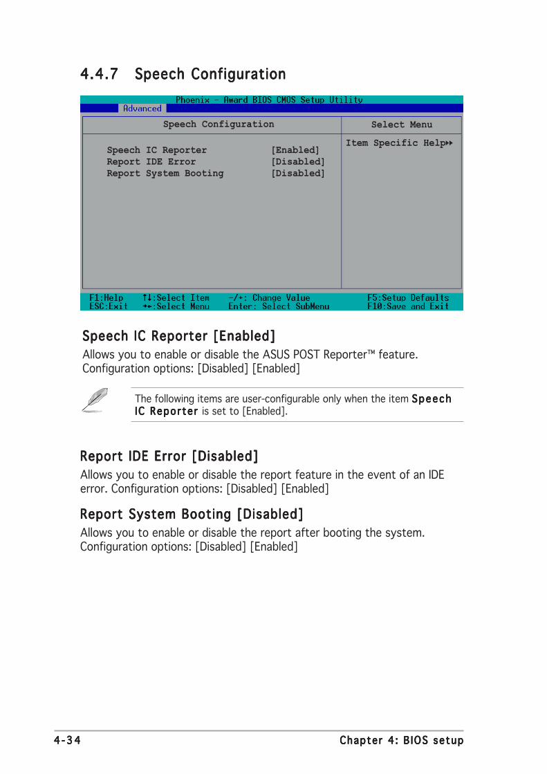
4 -344 -344 -344 -344 -34 Chapter 4 : B IOS setupChapter 4 : B IOS setupChapter 4 : B IOS setupChapter 4 : B IOS setupChapter 4 : B IOS setup
4.4.74.4.74.4.74.4.74.4.7 Speech ConfigurationSpeech ConfigurationSpeech ConfigurationSpeech ConfigurationSpeech Configuration
Speech IC Reporter [Enabled]Report IDE Error [Disabled]Report System Booting [Disabled]
Select Menu
Item Specific Help
Speech Configuration
The following items are user-configurable only when the item SpeechSpeechSpeechSpeechSpeechIC Reporter IC Reporter IC Reporter IC Reporter IC Reporter is set to [Enabled].
Speech IC Reporter [Enabled]Speech IC Reporter [Enabled]Speech IC Reporter [Enabled]Speech IC Reporter [Enabled]Speech IC Reporter [Enabled]
Allows you to enable or disable the ASUS POST Reporter™ feature.Configuration options: [Disabled] [Enabled]
Report IDE Error [Disabled]Report IDE Error [Disabled]Report IDE Error [Disabled]Report IDE Error [Disabled]Report IDE Error [Disabled]
Allows you to enable or disable the report feature in the event of an IDEerror. Configuration options: [Disabled] [Enabled]
Report System Booting [Disabled]Report System Booting [Disabled]Report System Booting [Disabled]Report System Booting [Disabled]Report System Booting [Disabled]
Allows you to enable or disable the report after booting the system.Configuration options: [Disabled] [Enabled]

ASUS K8N4-E De luxeASUS K8N4-E De luxeASUS K8N4-E De luxeASUS K8N4-E De luxeASUS K8N4-E De luxe 4 -354 -354 -354 -354 -35
4.4.84.4.84.4.84.4.84.4.8 Instant MusicInstant MusicInstant MusicInstant MusicInstant Music
Instant Music [Disabled]x Instant Music CD-ROM Drive Primary Master
Select Menu
Item Specific Help
Instant Music
Instant Music [Disabled]Instant Music [Disabled]Instant Music [Disabled]Instant Music [Disabled]Instant Music [Disabled]
Allows you to enable or disable the ASUS Instant Music feature.Configuration options: [Disabled] [Enabled]
Instant Music CD-ROM Drive [Primary Master]Instant Music CD-ROM Drive [Primary Master]Instant Music CD-ROM Drive [Primary Master]Instant Music CD-ROM Drive [Primary Master]Instant Music CD-ROM Drive [Primary Master]
Allows you to select the CD-ROM drive that you wish to use for the InstantMusic CD playback. This item is configurable only if the Instant Mus icInstant Mus icInstant Mus icInstant Mus icInstant Mus icitem is set to [Enabled]. Configuration options: [Primary Master] [PrimarySlave] [Secondary Master] [Secondary Slave]
Enabling Instant Music automatically disables the PS/2 keyboard powerup feature.

4 -364 -364 -364 -364 -36 Chapter 4 : B IOS setupChapter 4 : B IOS setupChapter 4 : B IOS setupChapter 4 : B IOS setupChapter 4 : B IOS setup
4.5 Power Menu
The Power menu allows you to reduce power consumption. This featureturns off the video display and shuts down the hard disk after a period ofinactivity.
4.5.14.5.14.5.14.5.14.5.1 ACPI Suspend Type [S1&S3]ACPI Suspend Type [S1&S3]ACPI Suspend Type [S1&S3]ACPI Suspend Type [S1&S3]ACPI Suspend Type [S1&S3]
Allows you to select the ACPI state used for system suspend.Configuration options: [S1(POS)] [S3(STR)] [S1&S3]
4.5.24.5.24.5.24.5.24.5.2 ACPI APIC Support [Enabled]ACPI APIC Support [Enabled]ACPI APIC Support [Enabled]ACPI APIC Support [Enabled]ACPI APIC Support [Enabled]
Allows you enable or disable the ACPI feature on the operating system.Configuration options: [Disabled] [Enabled]
ACPI Suspend Type [S1&S3]ACPI APIC Support [Enabled]APM Configuration Hardware Monitor
Select Menu
Item Specific Help
Select the ACPIstate used forSystem Suspend.
ASUS K8N4-E De luxeASUS K8N4-E De luxeASUS K8N4-E De luxeASUS K8N4-E De luxeASUS K8N4-E De luxe 4 -374 -374 -374 -374 -37
4.5.34.5.34.5.34.5.34.5.3 APM configurationAPM configurationAPM configurationAPM configurationAPM configuration
This menu shows the Advanced Power Management (APM) configurationsettings. Select an item then press <Enter> to display a pop-up menu withthe configuration options.
Select Menu
Item Specific HelpRestore on AC Power Loss [Disabled]PWR Button < 4 secs [Instant-Off]Power On by PCI Devices [Disabled]Power On by External Modems [Disabled]Power On by RTC Alarm [Disabled]
x Date (of Month) 0x Resume Time (hh:mm:ss) 0 : 0 : 0PPower On by PS/2 Mouse [Disabled]Power On by PS/2 Keyboard [Disabled]
APM Configuration
Restore on AC Power Loss [Disabled]Restore on AC Power Loss [Disabled]Restore on AC Power Loss [Disabled]Restore on AC Power Loss [Disabled]Restore on AC Power Loss [Disabled]
Allows you to enable or disable system reboot after power interruptions.Configuration options: [Disabled] [Enabled]
PWR Button < 4 secs [Instant-Off]PWR Button < 4 secs [Instant-Off]PWR Button < 4 secs [Instant-Off]PWR Button < 4 secs [Instant-Off]PWR Button < 4 secs [Instant-Off]
Allows you to set the event after the power button is pressed for morethan 4 seconds. Configuration options: [Suspend] [Instant-Off]
Power On by PCI Devices [Disabled]Power On by PCI Devices [Disabled]Power On by PCI Devices [Disabled]Power On by PCI Devices [Disabled]Power On by PCI Devices [Disabled]
When set to [Enabled], this parameter allows you to turn on the systemthrough a PCI LAN or modem card. This feature requires an ATX powersupply that provides at least 1A on the +5VSB lead.Configuration options: [Disabled] [Enabled]

4 -384 -384 -384 -384 -38 Chapter 4 : B IOS setupChapter 4 : B IOS setupChapter 4 : B IOS setupChapter 4 : B IOS setupChapter 4 : B IOS setup
The two succeeding items become configurable only when thePower-On By RTC A la rmPower-On By RTC A la rmPower-On By RTC A la rmPower-On By RTC A la rmPower-On By RTC A la rm item is set to [Enabled].
Day of Month Alarm [0]Day of Month Alarm [0]Day of Month Alarm [0]Day of Month Alarm [0]Day of Month Alarm [0]
To set the date of alarm, highlight this item and press <Enter> to displaythe Day of Month Alarm pop-up menu. Key-in a value within the specifiedrange then press <Enter>. Configuration options: [Min=0] [Max=31]
Time (hh:mm:ss) Alarm [0:0:0]Time (hh:mm:ss) Alarm [0:0:0]Time (hh:mm:ss) Alarm [0:0:0]Time (hh:mm:ss) Alarm [0:0:0]Time (hh:mm:ss) Alarm [0:0:0]
To set the time of alarm:
1. Highlight this item and press <Enter> to display a pop-up menu for thehour field.
2. Key-in a value (Min=0, Max=23), then press <Enter>.
3. Press <TAB> to move to the minutes field then press <Enter>.
4. Key-in a minute value (Min=0, Max=59), then press <Enter>.
5. Press <TAB> to move to the seconds field then press <Enter>.
6. Key-in a value (Min=0, Max=59), then press <Enter>.
The computer cannot receive or transmit data until the computer andaplications are fully running. Thus, connectino cannot be made on thefirst try. Turning an external modem off and then back on while thecomputer is off causes an initialization string that turns the systempower on.
Power-On By Alarm [Disabled]Power-On By Alarm [Disabled]Power-On By Alarm [Disabled]Power-On By Alarm [Disabled]Power-On By Alarm [Disabled]
Allows you to enable or disable RTC to generate a wake event. When thisitem is set to Enabled, the items Date of Month Alarm and Time (hh:mm:ss)Alarm items become user-configurable with set values.Configuration options: [Disabled] [Enabled]
Power On by External Modems [Disabled]Power On by External Modems [Disabled]Power On by External Modems [Disabled]Power On by External Modems [Disabled]Power On by External Modems [Disabled]
This allows either settings of [Enabled] or [Disabled] for powering up thecomputer when the external modem receives a call while the computer is inSoft-off mode. Configuration options: [Disabled] [Enabled]

ASUS K8N4-E De luxeASUS K8N4-E De luxeASUS K8N4-E De luxeASUS K8N4-E De luxeASUS K8N4-E De luxe 4 -394 -394 -394 -394 -39
Power On by PS/2 Mouse [Disabled]Power On by PS/2 Mouse [Disabled]Power On by PS/2 Mouse [Disabled]Power On by PS/2 Mouse [Disabled]Power On by PS/2 Mouse [Disabled]
Allows you to disable the Power On by PS/2 keyboard function or setspecific keys on the PS/2 keyboard to turn on the system. This featurerequires an ATX power supply that provides at least 1A on the +5VSB lead.Configuration options: [Disabled] [Enabled]
Power On by PS/2 Keyboard [Disabled]Power On by PS/2 Keyboard [Disabled]Power On by PS/2 Keyboard [Disabled]Power On by PS/2 Keyboard [Disabled]Power On by PS/2 Keyboard [Disabled]
This parameter allows you to turn on the system using specified keyboardkeys. This feature requires an ATX power supply that provides at least 1Aon the +5VSB lead. Configuration options: [Disabled] [Space Bar][Ctrl+ESC] [Power key]
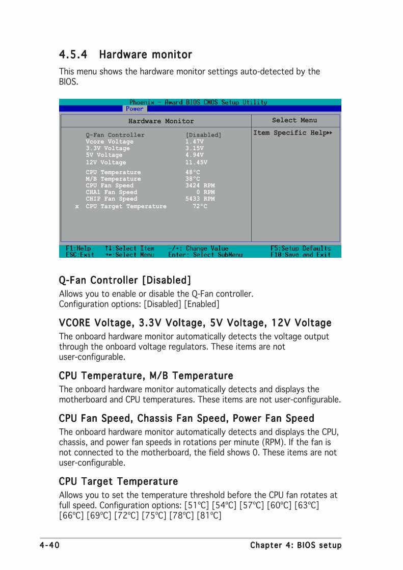
4 -404 -404 -404 -404 -40 Chapter 4 : B IOS setupChapter 4 : B IOS setupChapter 4 : B IOS setupChapter 4 : B IOS setupChapter 4 : B IOS setup
4.5.44.5.44.5.44.5.44.5.4 Hardware monitorHardware monitorHardware monitorHardware monitorHardware monitor
This menu shows the hardware monitor settings auto-detected by theBIOS.
Q-Fan Controller [Disabled]Vcore Voltage 1.47V3.3V Voltage 3.15V5V Voltage 4.94V12V Voltage 11.45V
CPU Temperature 48ºCM/B Temperature 38ºCCPU Fan Speed 3424 RPMCHA1 Fan Speed 0 RPMCHIP Fan Speed 5433 RPM
x CPU Target Temperature 72ºC
Select Menu
Item Specific Help
Hardware Monitor
Q-Fan Controller [Disabled]Q-Fan Controller [Disabled]Q-Fan Controller [Disabled]Q-Fan Controller [Disabled]Q-Fan Controller [Disabled]
Allows you to enable or disable the Q-Fan controller.Configuration options: [Disabled] [Enabled]
VCORE Voltage, 3.3V Voltage, 5V Voltage, 12V VoltageVCORE Voltage, 3.3V Voltage, 5V Voltage, 12V VoltageVCORE Voltage, 3.3V Voltage, 5V Voltage, 12V VoltageVCORE Voltage, 3.3V Voltage, 5V Voltage, 12V VoltageVCORE Voltage, 3.3V Voltage, 5V Voltage, 12V Voltage
The onboard hardware monitor automatically detects the voltage outputthrough the onboard voltage regulators. These items are notuser-configurable.
CPU Temperature, M/B TemperatureCPU Temperature, M/B TemperatureCPU Temperature, M/B TemperatureCPU Temperature, M/B TemperatureCPU Temperature, M/B Temperature
The onboard hardware monitor automatically detects and displays themotherboard and CPU temperatures. These items are not user-configurable.
CPU Fan Speed, Chassis Fan Speed, Power Fan SpeedCPU Fan Speed, Chassis Fan Speed, Power Fan SpeedCPU Fan Speed, Chassis Fan Speed, Power Fan SpeedCPU Fan Speed, Chassis Fan Speed, Power Fan SpeedCPU Fan Speed, Chassis Fan Speed, Power Fan Speed
The onboard hardware monitor automatically detects and displays the CPU,chassis, and power fan speeds in rotations per minute (RPM). If the fan isnot connected to the motherboard, the field shows 0. These items are notuser-configurable.
CPU Target TemperatureCPU Target TemperatureCPU Target TemperatureCPU Target TemperatureCPU Target Temperature
Allows you to set the temperature threshold before the CPU fan rotates atfull speed. Configuration options: [51ºC] [54ºC] [57ºC] [60ºC] [63ºC][66ºC] [69ºC] [72ºC] [75ºC] [78ºC] [81ºC]

ASUS K8N4-E De luxeASUS K8N4-E De luxeASUS K8N4-E De luxeASUS K8N4-E De luxeASUS K8N4-E De luxe 4 -414 -414 -414 -414 -41
1st ~ xth Boot Device1st ~ xth Boot Device1st ~ xth Boot Device1st ~ xth Boot Device1st ~ xth Boot Device
These items specify the boot device priority sequence from the availabledevices. The number of devices that appears on the screen depends on thenumber of devices installed in the system. Configuration options:[Removable] [Hard Disk] [CDROM] [Legacy LAN] [Disabled]
4.6 Boot Menu
This Boot menu items allow you to change the system boot settings.Select an item then press <Enter> to display a pop-up menu with theconfiguration options.
Boot Device Priority Removable DrivesHard Drisk DrivesCDROM DrivesBoot Settings ConfigurationSecurity
Select Menu
Item Specific Help
Select Boot DevicePriority
4.6.14.6.14.6.14.6.14.6.1 Boot Device PriorityBoot Device PriorityBoot Device PriorityBoot Device PriorityBoot Device Priority
Select Menu
Item Specific Help
Select your BootDevice Priority
1st Boot Device [Removable]2nd Boot Device [Hard Disk]3rd Boot Device [CDROM]4th Boot Device [Disabled]
Boot Device Priority

4 -424 -424 -424 -424 -42 Chapter 4 : B IOS setupChapter 4 : B IOS setupChapter 4 : B IOS setupChapter 4 : B IOS setupChapter 4 : B IOS setup
4.6.24.6.24.6.24.6.24.6.2 Removable drivesRemovable drivesRemovable drivesRemovable drivesRemovable drives
Removable Drives
1. Floppy Disks Item Specific Help
Use <up> or <down>arrow to select adevice, then press<+> to move it up,or <-> to move itdown the list. Press<ESC> to exit thismenu.
Select Menu
4.6.34.6.34.6.34.6.34.6.3 Hard Disk DrivesHard Disk DrivesHard Disk DrivesHard Disk DrivesHard Disk Drives
Hard Disk Drives
1. 1st Master: ST320410A2. Bootable Add-in Cards
Item Specific Help
Use <up> or <down>arrow to select adevice, then press<+> to move it up,or <-> to move itdown the list. Press<ESC> to exit thismenu.
Select Menu

ASUS K8N4-E De luxeASUS K8N4-E De luxeASUS K8N4-E De luxeASUS K8N4-E De luxeASUS K8N4-E De luxe 4 -434 -434 -434 -434 -43
4.6.44.6.44.6.44.6.44.6.4 CD-ROM drivesCD-ROM drivesCD-ROM drivesCD-ROM drivesCD-ROM drives
CDROM Drives
1. 1st Slave: ASUS CD-S520/A Item Specific Help
Use <up> or <down>arrow to select adevice, then press<+> to move it up,or <-> to move itdown the list. Press<ESC> to exit thismenu.
Select Menu
4.6.54.6.54.6.54.6.54.6.5 Boot settings configurationBoot settings configurationBoot settings configurationBoot settings configurationBoot settings configuration
Boot Settings COnfiguration
Case Open Warning [Enabled]Quick Boot [Enabled]Boot Up Floppy Seek [Disabled]Bootup Num-Lock [On]Typematic Rate Setting [Disabled]
x Typematic Rate (Chars/Sec) 6x Typematic Delay(Msec) 250
OS Select for DRAM > 64MB [Non-OS2]Full Screen LOGO [Enabled]Halt On [All Errors]
Item Specific Help
Allows the system toskip certain testswhile booting. Thiswill decrease thetime needed to bootthe system.
Select Menu
Case Open Warning[Enabled]Case Open Warning[Enabled]Case Open Warning[Enabled]Case Open Warning[Enabled]Case Open Warning[Enabled]
Setting to [Enabled] allows the system to send off a warning if the case orchassis is opened. Configuration options: [Disabled] [Enabled]
Quick Boot [Enabled]Quick Boot [Enabled]Quick Boot [Enabled]Quick Boot [Enabled]Quick Boot [Enabled]
Setting to [Enabled] allows the system to skip certain tests while booting,decreasing the time needed to boot the system.Configuration options: [Disabled] [Enabled]

4 -444 -444 -444 -444 -44 Chapter 4 : B IOS setupChapter 4 : B IOS setupChapter 4 : B IOS setupChapter 4 : B IOS setupChapter 4 : B IOS setup
The items Typemat ic Rate (Chars/Sec)Typemat ic Rate (Chars/Sec)Typemat ic Rate (Chars/Sec)Typemat ic Rate (Chars/Sec)Typemat ic Rate (Chars/Sec) and Typemat ic De layTypemat ic De layTypemat ic De layTypemat ic De layTypemat ic De lay(Msec)(Msec)(Msec)(Msec)(Msec) becomes user-configurable only when the item Typematic RateSetting is enabled.
Boot Up Floppy Seek [Disabled]Boot Up Floppy Seek [Disabled]Boot Up Floppy Seek [Disabled]Boot Up Floppy Seek [Disabled]Boot Up Floppy Seek [Disabled]
Enables or disables the chassis open status feature. Setting to Enabled,clears the chassis open status. Configuration options: [Disabled] [Enabled]
Bootup Num-Lock [On]Bootup Num-Lock [On]Bootup Num-Lock [On]Bootup Num-Lock [On]Bootup Num-Lock [On]
Allows you to select the power-on state for the NumLock.Configuration options: [Off] [On]
Typematic Rate Setting [Disabled]Typematic Rate Setting [Disabled]Typematic Rate Setting [Disabled]Typematic Rate Setting [Disabled]Typematic Rate Setting [Disabled]
Allows you to set the keystroke rate. Enable this item to configure theTypematic Rate (Chars/Sec) Typematic Rate (Chars/Sec) Typematic Rate (Chars/Sec) Typematic Rate (Chars/Sec) Typematic Rate (Chars/Sec) and the Typematic Delay (Msec)Typematic Delay (Msec)Typematic Delay (Msec)Typematic Delay (Msec)Typematic Delay (Msec).Configuration options: [Disabled] [Enabled]
Typematic Rate (Chars/Sec) [6]Typematic Rate (Chars/Sec) [6]Typematic Rate (Chars/Sec) [6]Typematic Rate (Chars/Sec) [6]Typematic Rate (Chars/Sec) [6]
Allows you to select the rate at which a character repeats when you hold akey. Configuration options: [6] [8] [10] [12] [15] [20] [24] [30]
Typematic Delay (Msec) [250]Typematic Delay (Msec) [250]Typematic Delay (Msec) [250]Typematic Delay (Msec) [250]Typematic Delay (Msec) [250]
Allows you to set the delay before keystrokes begin to repeat.Configuration options: [250] [500] [750] [1000]
OS Select for DRAM > 64MB [Non-OS2]OS Select for DRAM > 64MB [Non-OS2]OS Select for DRAM > 64MB [Non-OS2]OS Select for DRAM > 64MB [Non-OS2]OS Select for DRAM > 64MB [Non-OS2]
Set this item to OS2 only when you are running on an OS/2 operatingsystem with an installed RAM of greater than 64 KB.Configuration options: [Non-OS2] [OS2]
Full Screen LOGO [Enabled]Full Screen LOGO [Enabled]Full Screen LOGO [Enabled]Full Screen LOGO [Enabled]Full Screen LOGO [Enabled]
Allows you to enable or disable the full screen logo display feature.Configuration options: [Disabled] [Enabled]
• Make sure that the above item is set to [Enabled] if you want to usethe ASUS MyLogo2™ feature.
• See section “5.3.1 ASUS MyLogo2™” for details.
Halt On [All Errors]Halt On [All Errors]Halt On [All Errors]Halt On [All Errors]Halt On [All Errors]
Allows you to error report type.Configuration options: [All Errors] [No Errors] [All, But Keyboard][All, But Diskette] [All, But Disk/Key]

ASUS K8N4-E De luxeASUS K8N4-E De luxeASUS K8N4-E De luxeASUS K8N4-E De luxeASUS K8N4-E De luxe 4 -454 -454 -454 -454 -45
Supervisor Password [Clear]Supervisor Password [Clear]Supervisor Password [Clear]Supervisor Password [Clear]Supervisor Password [Clear]User Password [Clear]User Password [Clear]User Password [Clear]User Password [Clear]User Password [Clear]
These fields allow you to set passwords.
To set a password:
1. Highlight an item then press <Enter>.
2. Type in a password using eight (8) alphanumeric characters, thenpress <Enter>.
3. When prompted, confirm the password by typing the exact charactersagain, then press <Enter>. The password field setting is changed to[Set].
To clear the password:
1. Highlight the password field, and press <Enter> twice. The followingmessage appears:
“PASSWORD DISABLED!!! Press any key to continue...”
2. Press any key to return to the menu.
A note about passwordsA note about passwordsA note about passwordsA note about passwordsA note about passwords
The Supervisor password is required to enter the BIOS Setup programpreventing unauthorized access. The User password is required to boot thesystem preventing unauthorized use.
4.6.64.6.64.6.64.6.64.6.6 SecuritySecuritySecuritySecuritySecurity
Security
Supervisor Password ClearUser Password ClearPassword Check [Setup]
Item Specific Help
Supervisor passwordcontrols fullaccess, <Enter> tochange password.
Select Menu

4 -464 -464 -464 -464 -46 Chapter 4 : B IOS setupChapter 4 : B IOS setupChapter 4 : B IOS setupChapter 4 : B IOS setupChapter 4 : B IOS setup
Forgot the password?
If you forget your password, you can clear it by erasing the CMOS RealTime Clock (RTC) RAM. The RAM data containing the passwordinformation is powered by the onboard button cell battery. If you needto erase the CMOS RAM, refer to section “2.6 Jumpers” forinstructions.
Password Check [Setup]Password Check [Setup]Password Check [Setup]Password Check [Setup]Password Check [Setup]
This field requires you to enter the password before entering the BIOSsetup or the system. Select [Setup] to require the password beforeentering the BIOS Setup. Select [System] to require the password beforeentering the system. Configuration options: [Setup] [System]
4.7 Exit menu
The Exit menu items allow you to load the BIOS setup default settings,save or discard any changes you made, or exit the Setup utility.
Exit & Save ChangesExit & Discard ChangesLoad Setup DefaultDiscard Changes
Item Specific Help
This option savesdata to CMOS andexits the setupmenu.
Select Menu
Exit & Save ChangesExit & Save ChangesExit & Save ChangesExit & Save ChangesExit & Save Changes
Select this option then press <Enter>, or simply press <F10>, to save yourchanges to CMOS before exiting the Setup utility.
When a confirmation window appears (with a blinking [Y]):
• press <Enter> to save and exit
• type [N], then press <Enter>, or simply press <Esc>, to cancel thecommand and return to the Exit menu

ASUS K8N4-E De luxeASUS K8N4-E De luxeASUS K8N4-E De luxeASUS K8N4-E De luxeASUS K8N4-E De luxe 4 -474 -474 -474 -474 -47
Exit & Discard ChangesExit & Discard ChangesExit & Discard ChangesExit & Discard ChangesExit & Discard Changes
Select this option only if you do not want to save the changes that youmade to the Setup program. If you made changes to fields other thansystem date, system time, and password, the BIOS asks for a confirmationbefore exiting.
Load Setup DefaultsLoad Setup DefaultsLoad Setup DefaultsLoad Setup DefaultsLoad Setup Defaults
This option allows you to load the default values for each of theparameters on the Setup menus. When you select this option or if youpress <F5>, a confirmation window appears. Select [Yes] to load defaultvalues. Select Exit Saving Changes or make other changes before savingthe values to the non-volatile RAM.
Discard ChangesDiscard ChangesDiscard ChangesDiscard ChangesDiscard Changes
This option allows you to discard the selections you made and restore thepreviously saved values. After selecting this option, a confirmation appears.Select [Yes] to discard any changes and load the previously saved values.

4 -484 -484 -484 -484 -48 Chapter 4 : B IOS setupChapter 4 : B IOS setupChapter 4 : B IOS setupChapter 4 : B IOS setupChapter 4 : B IOS setup

5Softwaresupport
This chapter describes the contentsof the support CD that comes withthe motherboard package.

ASUS K8N4-E De luxeASUS K8N4-E De luxeASUS K8N4-E De luxeASUS K8N4-E De luxeASUS K8N4-E De luxe
Chapter summary 55.1 Installing an operating system ............................................. 5-1
5.2 Support CD information ........................................................ 5-1
5.3 Software information ........................................................... 5-8
5.4 RAID configurations ............................................................ 5-31
5.5 Creating a RAID driver disk ................................................. 5-50
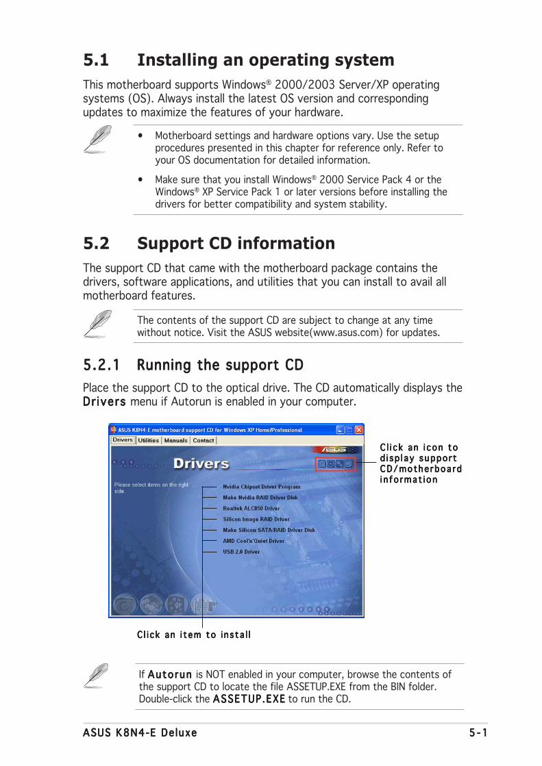
ASUS K8N4-E De luxeASUS K8N4-E De luxeASUS K8N4-E De luxeASUS K8N4-E De luxeASUS K8N4-E De luxe 5 - 15 - 15 - 15 - 15 - 1
If Auto run Auto run Auto run Auto run Auto run is NOT enabled in your computer, browse the contents ofthe support CD to locate the file ASSETUP.EXE from the BIN folder.Double-click the ASSETUP .EXEASSETUP .EXEASSETUP .EXEASSETUP .EXEASSETUP .EXE to run the CD.
C l i c k an i t em to i n s ta l lC l i c k an i t em to i n s ta l lC l i c k an i t em to i n s ta l lC l i c k an i t em to i n s ta l lC l i c k an i t em to i n s ta l l
5.1 Installing an operating system
This motherboard supports Windows® 2000/2003 Server/XP operatingsystems (OS). Always install the latest OS version and correspondingupdates to maximize the features of your hardware.
5.2 Support CD information
The support CD that came with the motherboard package contains thedrivers, software applications, and utilities that you can install to avail allmotherboard features.
5.2.15.2.15.2.15.2.15.2.1 Running the support CDRunning the support CDRunning the support CDRunning the support CDRunning the support CD
Place the support CD to the optical drive. The CD automatically displays theDr ivers Dr ivers Dr ivers Dr ivers Dr ivers menu if Autorun is enabled in your computer.
• Motherboard settings and hardware options vary. Use the setupprocedures presented in this chapter for reference only. Refer toyour OS documentation for detailed information.
• Make sure that you install Windows® 2000 Service Pack 4 or theWindows® XP Service Pack 1 or later versions before installing thedrivers for better compatibility and system stability.
The contents of the support CD are subject to change at any timewithout notice. Visit the ASUS website(www.asus.com) for updates.
C l i c k an i con toC l i c k an i con toC l i c k an i con toC l i c k an i con toC l i c k an i con tod i sp l ay suppo r td i sp l ay suppo r td i sp l ay suppo r td i sp l ay suppo r td i sp l ay suppo r tCD/mothe rboa rdCD/mothe rboa rdCD/mothe rboa rdCD/mothe rboa rdCD/mothe rboa rdi n f o rmat i oni n f o rmat i oni n f o rmat i oni n f o rmat i oni n f o rmat i on

5 - 25 - 25 - 25 - 25 - 2 Chapter 5 : Software supportChapter 5 : Software supportChapter 5 : Software supportChapter 5 : Software supportChapter 5 : Software support
5.2.25.2.25.2.25.2.25.2.2 Drivers menuDrivers menuDrivers menuDrivers menuDrivers menu
The drivers menu shows the available device drivers if the system detectsinstalled devices. Install the necessary drivers to activate the devices.
Nvidia Chipset Driver ProgramNvidia Chipset Driver ProgramNvidia Chipset Driver ProgramNvidia Chipset Driver ProgramNvidia Chipset Driver Program
Installs the NVIDIA® chipset drivers for the NVIDIA® nForce™4-4X chipset.
Make an Nvidia Chipset Driver DiskMake an Nvidia Chipset Driver DiskMake an Nvidia Chipset Driver DiskMake an Nvidia Chipset Driver DiskMake an Nvidia Chipset Driver Disk
Allows you to create the NVIDIA® driver disk for Serial ATA and RAIDfeatures.
Realtek ALC850 DriverRealtek ALC850 DriverRealtek ALC850 DriverRealtek ALC850 DriverRealtek ALC850 Driver
Allows you to install the Realtek ALC850 driver.
Si l icon Image RAID DriverSil icon Image RAID DriverSil icon Image RAID DriverSil icon Image RAID DriverSil icon Image RAID Driver
Installs the Silicon Image RAID Driver. See section “5.4.2 Silicon Image RAIDconfigurations” for details.
Make Sil icon SATA/RAID Driver DiskMake Sil icon SATA/RAID Driver DiskMake Sil icon SATA/RAID Driver DiskMake Sil icon SATA/RAID Driver DiskMake Sil icon SATA/RAID Driver Disk
Allows you to make a Silicon Image SATA Link™ Sil 3114 driver disk.
AMD Cool ‘n’ Quiet DriverAMD Cool ‘n’ Quiet DriverAMD Cool ‘n’ Quiet DriverAMD Cool ‘n’ Quiet DriverAMD Cool ‘n’ Quiet Driver
Installs the AMD Cool ‘n’ Quiet!™ Technology driver. Cool ‘n’ Quiet!™Technology allows the system to dynamically and automatically select theCPU speed, voltage, and power combination that matches the user’sperformance requirements. See section “5.3.2 Cool ‘n’ Quiet!™Technology” for details.
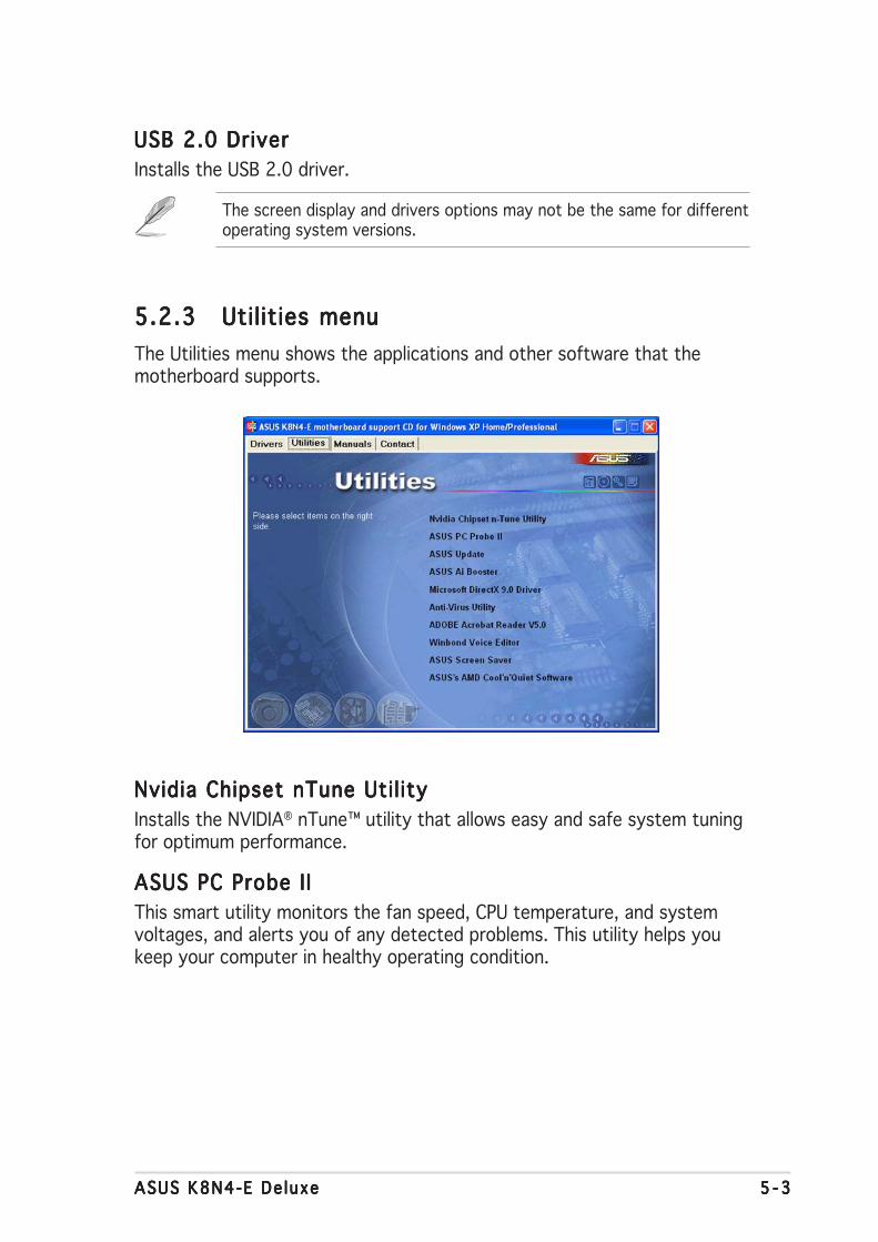
ASUS K8N4-E De luxeASUS K8N4-E De luxeASUS K8N4-E De luxeASUS K8N4-E De luxeASUS K8N4-E De luxe 5 - 35 - 35 - 35 - 35 - 3
The screen display and drivers options may not be the same for differentoperating system versions.
5.2.35.2.35.2.35.2.35.2.3 Utilities menuUtilities menuUtilities menuUtilities menuUtilities menu
The Utilities menu shows the applications and other software that themotherboard supports.
Nvidia Chipset nTune Util ityNvidia Chipset nTune Util ityNvidia Chipset nTune Util ityNvidia Chipset nTune Util ityNvidia Chipset nTune Util ity
Installs the NVIDIA® nTune™ utility that allows easy and safe system tuningfor optimum performance.
ASUS PC Probe I IASUS PC Probe I IASUS PC Probe I IASUS PC Probe I IASUS PC Probe I I
This smart utility monitors the fan speed, CPU temperature, and systemvoltages, and alerts you of any detected problems. This utility helps youkeep your computer in healthy operating condition.
USB 2.0 DriverUSB 2.0 DriverUSB 2.0 DriverUSB 2.0 DriverUSB 2.0 Driver
Installs the USB 2.0 driver.

5 - 45 - 45 - 45 - 45 - 4 Chapter 5 : Software supportChapter 5 : Software supportChapter 5 : Software supportChapter 5 : Software supportChapter 5 : Software support
ASUS UpdateASUS UpdateASUS UpdateASUS UpdateASUS Update
The ASUS Update utility that allows you to update the motherboard BIOS inWindows® environment. This utility requires an Internet connection eitherthrough a network or an Internet Service Provider (ISP). See section “4.1.5ASUS Update utility” for details.
Before using the ASUS Update, make sure that you have an Internetconnection so you can connect to the ASUS website.
The screen display and utilities option may not be the same for differentoperating system versions.
ASUS ASUS ASUS ASUS ASUS AI BoosterAI BoosterAI BoosterAI BoosterAI Booster
The ASUS AI Booster application allows you to overclock the CPU speed inWindows® environment.
Microsoft DirectX 9.0 DriverMicrosoft DirectX 9.0 DriverMicrosoft DirectX 9.0 DriverMicrosoft DirectX 9.0 DriverMicrosoft DirectX 9.0 Driver
Installs the Microsoft® DirectX 9.0 driver.
Anti-virus uti l ityAnti-virus uti l ityAnti-virus uti l ityAnti-virus uti l ityAnti-virus uti l ity
The anti-virus application scans, identifies, and removes computer viruses.View the online help for detailed information.
ADOBE Acrobat ReaderADOBE Acrobat ReaderADOBE Acrobat ReaderADOBE Acrobat ReaderADOBE Acrobat Reader
Installs the Adobe® Acrobat® Reader V5.0 that allows you to open, view,and print documents in Portable Document Format (PDF).
Winbond Voice EditorWinbond Voice EditorWinbond Voice EditorWinbond Voice EditorWinbond Voice Editor
This program is for recording and customizing wave files for the ASUSPOST Reporter™. Use this program to change the default vocal POSTmessages. See section “3.3 Vocal POST Messages” for a list of the defaultmessages.
ASUS Screen SaverASUS Screen SaverASUS Screen SaverASUS Screen SaverASUS Screen Saver
Installs the ASUS screen saver.
ASUS AMD Cool ‘n’ Quiet SoftwareASUS AMD Cool ‘n’ Quiet SoftwareASUS AMD Cool ‘n’ Quiet SoftwareASUS AMD Cool ‘n’ Quiet SoftwareASUS AMD Cool ‘n’ Quiet Software
Installs the AMD Cool ‘n’ Quiet!™ Technology software.

ASUS K8N4-E De luxeASUS K8N4-E De luxeASUS K8N4-E De luxeASUS K8N4-E De luxeASUS K8N4-E De luxe 5 - 55 - 55 - 55 - 55 - 5
5.2.45.2.45.2.45.2.45.2.4 Manuals menuManuals menuManuals menuManuals menuManuals menu
The Manua ls Manua ls Manua ls Manua ls Manua ls menu contains the user manuals for third party componentsand applications.
• Most user manual files are in Portable Document Format (PDF).Install the Adobe® Acrobat® Reader from the Ut i l i t i es Ut i l i t i es Ut i l i t i es Ut i l i t i es Ut i l i t i es menu beforeopening a user manual file.
• Some user manuals listed in this menu may not be applicable for thismotherboard model.
NVIDIA Firewall Administrator’s GuideNVIDIA Firewall Administrator’s GuideNVIDIA Firewall Administrator’s GuideNVIDIA Firewall Administrator’s GuideNVIDIA Firewall Administrator’s Guide
Allows you to open the NVIDIA® ForceWare Networking and FirewallAdministrator’s Guide.
NVIDIA RAID User’s GuideNVIDIA RAID User’s GuideNVIDIA RAID User’s GuideNVIDIA RAID User’s GuideNVIDIA RAID User’s Guide
Allows you to open the NVIDIA® RAID User’s Guide.
Si l3114 User’s ManualSil3114 User’s ManualSil3114 User’s ManualSil3114 User’s ManualSil3114 User’s Manual
Allows you to open the Silicon Image SATARaid™ Serial ATA RAIDManagement Software user’s manual.
NVIDIA nTune ManualNVIDIA nTune ManualNVIDIA nTune ManualNVIDIA nTune ManualNVIDIA nTune Manual
Allows you to open the NVIDIA® nTune™ user’s manual.
NvRAID Disk Alert User’s GuideNvRAID Disk Alert User’s GuideNvRAID Disk Alert User’s GuideNvRAID Disk Alert User’s GuideNvRAID Disk Alert User’s Guide
Allows you to open the NVIDIA® NvRAID™ user’s manual.

5 - 65 - 65 - 65 - 65 - 6 Chapter 5 : Software supportChapter 5 : Software supportChapter 5 : Software supportChapter 5 : Software supportChapter 5 : Software support
5.2.65.2.65.2.65.2.65.2.6 Other informationOther informationOther informationOther informationOther information
The icons on the top right corner of the screen give additional informationon the motherboard and the contents of the support CD. Click an icon todisplay the specified information.
Motherboard InfoMotherboard InfoMotherboard InfoMotherboard InfoMotherboard Info
Displays the general specifications of the motherboard.
5.2.55.2.55.2.55.2.55.2.5 ASUS Contact informationASUS Contact informationASUS Contact informationASUS Contact informationASUS Contact information
Click the Contact Contact Contact Contact Contact tab to display the ASUS contact information. You canalso find this information on the inside front cover of this user guide.

ASUS K8N4-E De luxeASUS K8N4-E De luxeASUS K8N4-E De luxeASUS K8N4-E De luxeASUS K8N4-E De luxe 5 - 75 - 75 - 75 - 75 - 7
Technical support FormTechnical support FormTechnical support FormTechnical support FormTechnical support Form
Displays the ASUS Technical Support Request Form that you have to fill outwhen requesting technical support.
Fi le l istFi lel istFi lel istFi lel istFi lel ist
Displays the contents of the support CD and a brief description of each intext format.
Browse this CDBrowse this CDBrowse this CDBrowse this CDBrowse this CD
Displays the support CD contents in graphical format.
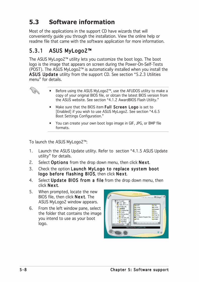
5 - 85 - 85 - 85 - 85 - 8 Chapter 5 : Software supportChapter 5 : Software supportChapter 5 : Software supportChapter 5 : Software supportChapter 5 : Software support
5.3 Software information
Most of the applications in the support CD have wizards that willconveniently guide you through the installation. View the online help orreadme file that came with the software application for more information.
5.3.15.3.15.3.15.3.15.3.1 ASUS MyLogo2™ASUS MyLogo2™ASUS MyLogo2™ASUS MyLogo2™ASUS MyLogo2™
The ASUS MyLogo2™ utility lets you customize the boot logo. The bootlogo is the image that appears on screen during the Power-On-Self-Tests(POST). The ASUS MyLogo2™ is automatically installed when you install theASUS Update ASUS Update ASUS Update ASUS Update ASUS Update utility from the support CD. See section “5.2.3 Utilitiesmenu” for details.
To launch the ASUS MyLogo2™:
1. Launch the ASUS Update utility. Refer to section “4.1.5 ASUS Updateutility” for details.
2. Select Opt ions Opt ions Opt ions Opt ions Opt ions from the drop down menu, then click NextNextNextNextNext.
3. Check the option Launch MyLogo to replace system bootLaunch MyLogo to replace system bootLaunch MyLogo to replace system bootLaunch MyLogo to replace system bootLaunch MyLogo to replace system bootlogo before f lash ing BIOSlogo before f lash ing BIOSlogo before f lash ing BIOSlogo before f lash ing BIOSlogo before f lash ing BIOS, then click NextNextNextNextNext.
4. Select Update BIOS from a f i leUpdate BIOS from a f i leUpdate BIOS from a f i leUpdate BIOS from a f i leUpdate BIOS from a f i le from the drop down menu, thenclick NextNextNextNextNext.
5. When prompted, locate the newBIOS file, then click NextNextNextNextNext. TheASUS MyLogo2 window appears.
6. From the left window pane, selectthe folder that contains the imageyou intend to use as your bootlogo.
• Before using the ASUS MyLogo2™, use the AFUDOS utility to make acopy of your original BIOS file, or obtain the latest BIOS version fromthe ASUS website. See section “4.1.2 AwardBIOS Flash Utility.”
• Make sure that the BIOS item Fu l l Screen Logo Fu l l Screen Logo Fu l l Screen Logo Fu l l Screen Logo Fu l l Screen Logo is set to[Enabled] if you wish to use ASUS MyLogo2. See section “4.6.5Boot Settings Configuration.”
• You can create your own boot logo image in GIF, JPG, or BMP fileformats.

ASUS K8N4-E De luxeASUS K8N4-E De luxeASUS K8N4-E De luxeASUS K8N4-E De luxeASUS K8N4-E De luxe 5 - 95 - 95 - 95 - 95 - 9
9. When the screen returns to the ASUS Update utility, flash the originalBIOS to load the new boot logo.
10. After flashing the BIOS, restart the computer to display the new bootlogo during POST.
8. Adjust the boot image to yourdesired size by selecting a valueon the Rat io Rat io Rat io Rat io Rat io box.
7. When the logo images appear onthe right window pane, select animage to enlarge by clicking on it.

5 -105 -105 -105 -105 -10 Chapter 5 : Software supportChapter 5 : Software supportChapter 5 : Software supportChapter 5 : Software supportChapter 5 : Software support
3. Click the R unRunRunRunRun button to perform a cable test.
5.3.25.3.25.3.25.3.25.3.2 AI NET2AI NET2AI NET2AI NET2AI NET2
The AI NET2 features the Marvell® Virtual Cable Tester™ (VCT). VCT is acable diagnostic utility that reports LAN cable faults and shorts using theTime Domain Reflectometry (TDR) technology. The VCT detects andreports open and shorted cables, impedance mismatches, pair swaps, pairpolarity problems, and pair skew problems of up to 64 ns at one meteraccuracy.
The VCT feature reduces networking and support costs through a highlymanageable and controlled network system. This utility can be incorporatedin the network systems sofware for ideal field support as well asdevelopment diagnostics.
Using the Virtual Cable Tester™Using the Virtual Cable Tester™Using the Virtual Cable Tester™Using the Virtual Cable Tester™Using the Virtual Cable Tester™
To use the the Marvell® Virtual Cable Tester™ utility:
1. Launch the VCT utility from the Windows® desktop by clickingStart > Al l Programs > Marvel l > Virtua l Cable TesterStart > Al l Programs > Marvel l > Virtua l Cable TesterStart > Al l Programs > Marvel l > Virtua l Cable TesterStart > Al l Programs > Marvel l > Virtua l Cable TesterStart > Al l Programs > Marvel l > Virtua l Cable Tester.
2. Click Virtua l Cable Tester Virtua l Cable Tester Virtua l Cable Tester Virtua l Cable Tester Virtua l Cable Tester from the menu to display the screenbelow.
• The VCT only runs on systems with Windows® XP or Windows® 2000operating systems.
• The VCT utility only tests Ethernet cables connected to Gigabit LANport(s).
• The R u nR u nR u nR u nR u n button on the Virtual Cable Tester™ main window isdisabled if no problem is detected on the LAN cable(s) connected tothe LAN port(s).
• If you want the system to check the status of the LAN cable beforeentering the OS, enable the item Post Check LAN Cab le Post Check LAN Cab le Post Check LAN Cab le Post Check LAN Cab le Post Check LAN Cab le in theBIOS Setup.
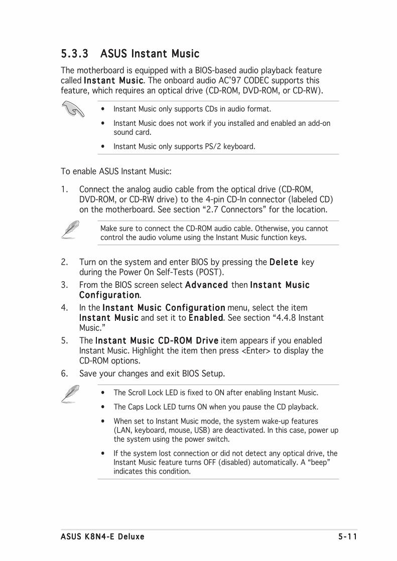
ASUS K8N4-E De luxeASUS K8N4-E De luxeASUS K8N4-E De luxeASUS K8N4-E De luxeASUS K8N4-E De luxe 5 -115 -115 -115 -115 -11
• Instant Music only supports CDs in audio format.
• Instant Music does not work if you installed and enabled an add-onsound card.
• Instant Music only supports PS/2 keyboard.
To enable ASUS Instant Music:
1. Connect the analog audio cable from the optical drive (CD-ROM,DVD-ROM, or CD-RW drive) to the 4-pin CD-In connector (labeled CD)on the motherboard. See section “2.7 Connectors” for the location.
Make sure to connect the CD-ROM audio cable. Otherwise, you cannotcontrol the audio volume using the Instant Music function keys.
5.3.35.3.35.3.35.3.35.3.3 ASUS Instant MusicASUS Instant MusicASUS Instant MusicASUS Instant MusicASUS Instant Music
The motherboard is equipped with a BIOS-based audio playback featurecalled Instant Mus icInstant Mus icInstant Mus icInstant Mus icInstant Mus ic. The onboard audio AC’97 CODEC supports thisfeature, which requires an optical drive (CD-ROM, DVD-ROM, or CD-RW).
2. Turn on the system and enter BIOS by pressing the De lete De lete De lete De lete De lete keyduring the Power On Self-Tests (POST).
3. From the BIOS screen select Advanced Advanced Advanced Advanced Advanced then Instant Mus icInstant Mus icInstant Mus icInstant Mus icInstant Mus icConf igurat ionConf igurat ionConf igurat ionConf igurat ionConf igurat ion.
4. In the Instant Music Conf igurat ionInstant Music Conf igurat ionInstant Music Conf igurat ionInstant Music Conf igurat ionInstant Music Conf igurat ion menu, select the itemInstant Mus icInstant Mus icInstant Mus icInstant Mus icInstant Mus ic and set it to Enab ledEnab ledEnab ledEnab ledEnab led. See section “4.4.8 InstantMusic.”
5. The Instant Music CD-ROM Dr iveInstant Music CD-ROM Dr iveInstant Music CD-ROM Dr iveInstant Music CD-ROM Dr iveInstant Music CD-ROM Dr ive item appears if you enabledInstant Music. Highlight the item then press <Enter> to display theCD-ROM options.
6. Save your changes and exit BIOS Setup.
• The Scroll Lock LED is fixed to ON after enabling Instant Music.
• The Caps Lock LED turns ON when you pause the CD playback.
• When set to Instant Music mode, the system wake-up features(LAN, keyboard, mouse, USB) are deactivated. In this case, power upthe system using the power switch.
• If the system lost connection or did not detect any optical drive, theInstant Music feature turns OFF (disabled) automatically. A “beep”indicates this condition.

5 -125 -125 -125 -125 -12 Chapter 5 : Software supportChapter 5 : Software supportChapter 5 : Software supportChapter 5 : Software supportChapter 5 : Software support
To use ASUS Instant Music:To use ASUS Instant Music:To use ASUS Instant Music:To use ASUS Instant Music:To use ASUS Instant Music:
1. Ensure that the power cord is plugged to a grounded power source, sothat the system has a standby power.
2. Use either one of the two sets of special function keys on yourkeyboard to play audio CDs. These keys only function as indicated ifyou enabled the Instant Music item in BIOS.
To guide you in using Instant Music, place the Instant Music label overthe function keys on the keyboard. The Instant Music keyboard labelcomes with your motherboard package.
Instant Music function keys (Set 2)
3. Connect speakers or a headphone to the Line Out (lime colored) porton the rear panel for audio output. You may also connect a headphoneto the headphone jack on the CD-ROM drive front panel.
4. Press <Esc> to turn ON Instant Music.
5. Place an audio CD on the CD-ROM drive.
6. Press <F1> or the <Space Bar> to play the first track on the CD.
Instant Music function keys (Set 1)
ASUS K8N4-E De luxeASUS K8N4-E De luxeASUS K8N4-E De luxeASUS K8N4-E De luxeASUS K8N4-E De luxe 5 -135 -135 -135 -135 -13
If there is no CD on the drive and you press < F 1 >< F 1 >< F 1 >< F 1 >< F 1 > or <Space Bar><Space Bar><Space Bar><Space Bar><Space Bar>,the drive tray ejects.
7. Refer to the Instant Music function key definitions on the previouspage to select other tracks or control the volume.
8. Press <F2> or <Enter> once to stop playing the CD.Press <F2> or <Enter> one more time to eject the CD.

5 -145 -145 -145 -145 -14 Chapter 5 : Software supportChapter 5 : Software supportChapter 5 : Software supportChapter 5 : Software supportChapter 5 : Software support
5.3.45.3.45.3.45.3.45.3.4 Cool ‘n’ Quiet!™ TechnologyCool ‘n’ Quiet!™ TechnologyCool ‘n’ Quiet!™ TechnologyCool ‘n’ Quiet!™ TechnologyCool ‘n’ Quiet!™ Technology
The motherboard supports the AMD Cool ‘n’ Quiet!™ Technology thatdynamically and automatically change the CPU speed, voltage, and amountof power depending on the task the CPU performs.
Enabling Cool ‘n’ Quiet!™ TechnologyEnabling Cool ‘n’ Quiet!™ TechnologyEnabling Cool ‘n’ Quiet!™ TechnologyEnabling Cool ‘n’ Quiet!™ TechnologyEnabling Cool ‘n’ Quiet!™ Technology
To enable Cool ‘n’ Quiet!™ Technology:
1. Turn on the system and enter BIOS by pressing the <Del> key duringthe Power On Self-Tests (POST).
2. Go to Advanced -> CPU Conf igurat ion -> AMD K8 CoolAdvanced -> CPU Conf igurat ion -> AMD K8 CoolAdvanced -> CPU Conf igurat ion -> AMD K8 CoolAdvanced -> CPU Conf igurat ion -> AMD K8 CoolAdvanced -> CPU Conf igurat ion -> AMD K8 Cool‘n ’Qu iet‘n ’Qu iet‘n ’Qu iet‘n ’Qu iet‘n ’Qu iet Contro l Contro l Contro l Contro l Contro l and set it to [Enabled]. See section “4.4Advanced Menu.”
3. In the Power Power Power Power Power menu, select the item ACPI 2.0 SupportACPI 2.0 SupportACPI 2.0 SupportACPI 2.0 SupportACPI 2.0 Support and set itto [Enabled]. See section “4.5 Power Menu.”
4. Save your changes and exit BIOS Setup.
5. Reboot your computer and set your Power Option Propertiesdepending on your operating system.
Windows® 2000/XP
1. From the Windows® 2000/XP operating system, click the Sta r tSta r tSta r tSta r tSta r tbutton. Select Sett ingsSett ingsSett ingsSett ingsSett ings, then Contro l Pane lContro l Pane lContro l Pane lContro l Pane lContro l Pane l.
2. Make sure the Control Panel is set to Classic View.
3. Double-click the D isp lay D isp lay D isp lay D isp lay D isp lay icon in the Control Panel then select theScreen SaverScreen SaverScreen SaverScreen SaverScreen Saver tab.
4. Click the Power . . .Power . . .Power . . .Power . . .Power . . . button.The following dialog boxappears.
5. From the Power schemesPower schemesPower schemesPower schemesPower schemescombo list box, selectMin imal PowerMin imal PowerMin imal PowerMin imal PowerMin imal PowerManagementManagementManagementManagementManagement.
6. Click OK OK OK OK OK to effect settings.
Make sure to install theCool ‘n’ Quiet!™ driver andapplication before usingthis feature.

ASUS K8N4-E De luxeASUS K8N4-E De luxeASUS K8N4-E De luxeASUS K8N4-E De luxeASUS K8N4-E De luxe 5 -155 -155 -155 -155 -15
Windows® 98 SE/Me
1. From the Windows® 98 SE/Me operating system, click the Sta r tSta r tSta r tSta r tSta r tbutton. Select Sett ingsSett ingsSett ingsSett ingsSett ings, then Contro l Pane lContro l Pane lContro l Pane lContro l Pane lContro l Pane l.
2. Double-click the D isp lay D isp lay D isp lay D isp lay D isp lay iconin the Control Panel thenselect the Screen SaverScreen SaverScreen SaverScreen SaverScreen Saver tab.
3. From the Energy sav ingEnergy sav ingEnergy sav ingEnergy sav ingEnergy sav ingfeatures of monitorfeatures of monitorfeatures of monitorfeatures of monitorfeatures of monitor group,click the Sett ings. . .Sett ings. . .Sett ings. . .Sett ings. . .Sett ings. . . button.
• Make sure to install the AMD Cool ‘n’ Quiet!™ driver and applicationbefore using this feature.
• The AMD Cool ‘n’ Quiet!™ technology feature works only with theAMD heatsink and fan assembly with monitor chip
• If you purchased a separate heatsink and fan package, use theASUS Q-Fan technology feature to automatically adjust the CPU fanspeed according to your system loading.
4. From the Power Opt ionsPower Opt ionsPower Opt ionsPower Opt ionsPower Opt ionsPropert iesPropert iesPropert iesPropert iesPropert ies dialog box,select the AMD’s Cool ‘n ’AMD’s Cool ‘n ’AMD’s Cool ‘n ’AMD’s Cool ‘n ’AMD’s Cool ‘n ’Quiet(tm) TechnologyQuiet(tm) TechnologyQuiet(tm) TechnologyQuiet(tm) TechnologyQuiet(tm) Technologytab.
5. Click the PerformancePerformancePerformancePerformancePerformancecombo list box to selectdesired mode. AutomaticMode is the recommendedsetting.
6. Click OK OK OK OK OK to effect settings.

5 -165 -165 -165 -165 -16 Chapter 5 : Software supportChapter 5 : Software supportChapter 5 : Software supportChapter 5 : Software supportChapter 5 : Software support
Launching the Cool ‘n’ Quiet!™ softwareLaunching the Cool ‘n’ Quiet!™ softwareLaunching the Cool ‘n’ Quiet!™ softwareLaunching the Cool ‘n’ Quiet!™ softwareLaunching the Cool ‘n’ Quiet!™ software
The motherboard support CD includes the Cool ‘n’ Quiet!™ software thatenables you to view your system’s real-time CPU Frequency and voltage.
To launch the Cool ‘n’ Quiet!™ program:
1. If you are using Windows® 98SE/Me/2000, click the Sta r tSta r tSta r tSta r tSta r t button.Select Programs-> ASUS -> Cool & Quiet -> Cool & Quiet.Programs-> ASUS -> Cool & Quiet -> Cool & Quiet.Programs-> ASUS -> Cool & Quiet -> Cool & Quiet.Programs-> ASUS -> Cool & Quiet -> Cool & Quiet.Programs-> ASUS -> Cool & Quiet -> Cool & Quiet.
2. If you are using Windows® XP, click the Sta r tSta r tSta r tSta r tSta r t button. Select A l lA l lA l lA l lA l lPrograms-> ASUS -> Cool & Quiet -> Cool & Quiet.Programs-> ASUS -> Cool & Quiet -> Cool & Quiet.Programs-> ASUS -> Cool & Quiet -> Cool & Quiet.Programs-> ASUS -> Cool & Quiet -> Cool & Quiet.Programs-> ASUS -> Cool & Quiet -> Cool & Quiet.
3. The Cool ‘n’ Quiet!™ technology screen appears and displays thecurrent CPU Frequency and CPU Voltage.
Make sure to install the Cool ‘n’ Quiet!™ software from the motherboardsupport CD. Refer to section “5.2.3 Utilities menu” for details.

ASUS K8N4-E De luxeASUS K8N4-E De luxeASUS K8N4-E De luxeASUS K8N4-E De luxeASUS K8N4-E De luxe 5 -175 -175 -175 -175 -17
5.3.55.3.55.3.55.3.55.3.5 Audio configurationsAudio configurationsAudio configurationsAudio configurationsAudio configurations
The Realtek® ALC850 AC ‘97 audio CODEC provides 8-channel audiocapability to deliver the ultimate audio experience on your PC. The softwareprovides Jack-Sensing function (Line-In, Line-Out, Mic-In), S/PDIF outsupport and interrupt capability. The ALC850 also includes the Realtek®
proprietary UAJ® (Universal Audio Jack) technology for three ports (Line-In,Line-Out and Mic-In), eliminating cable connection errors and giving usersplug and play convenience.
Follow the installation wizard to install the Realtek ALC850 AudioRealtek ALC850 AudioRealtek ALC850 AudioRealtek ALC850 AudioRealtek ALC850 AudioDr iver and Appl icat ionDr iver and Appl icat ionDr iver and Appl icat ionDr iver and Appl icat ionDr iver and Appl icat ion from the support CD that came with themotherboard package.
If the Realtek audio software is correctly installed, you will find theSoundEffect icon on the taskbar.
From the taskbar, double-click on theSoundEffect SoundEffect SoundEffect SoundEffect SoundEffect icon to display theRealtek Audio Contro l PanelRealtek Audio Contro l PanelRealtek Audio Contro l PanelRealtek Audio Contro l PanelRealtek Audio Contro l Panel.
Sound Effect optionsSound Effect optionsSound Effect optionsSound Effect optionsSound Effect options
The Realtek® ALC850 Audio CODEC allows you to set your listeningenvironment, adjust the equalizer, set the karaoke, or selectpre-programmed equalizer settings for your listening pleasure.
The Jack-sensing and UAJ® technology features are supported on theLine-In, Line-Out, and Mic jacks only.
Rea l t ek SoundE f fec t i conRea l tek SoundE f fec t i conRea l tek SoundE f fec t i conRea l tek SoundE f fec t i conRea l tek SoundE f fec t i con

5 -185 -185 -185 -185 -18 Chapter 5 : Software supportChapter 5 : Software supportChapter 5 : Software supportChapter 5 : Software supportChapter 5 : Software support
S/PDIF optionsS/PDIF optionsS/PDIF optionsS/PDIF optionsS/PDIF options
The Sony/Philips Digital Interface (S/PDIF) options allows you to changeyour S/PDIF output settings.
To set the S/PDIF options:
1. From the Realtek Audio Control Panel, click the SPD IF SPD IF SPD IF SPD IF SPD IF button.
2. Click the option buttons to change your S/PDIF out settings.
3. Click the Exit (XXXXX) button on the upper-right hand corner of the windowto exit.
To set the sound effect options:
1. From the Realtek Audio Control Panel, click the Sound EffectSound EffectSound EffectSound EffectSound Effectbutton.
2. Click the shortcut buttons to change the acoustic environment, adjustthe equalizer, or set the karaoke to your desired settings.
3. The audio settings take effect immediately after you click on thebuttons.
4. Click the Exit (XXXXX) button on the upper-right hand corner of the windowto exit.
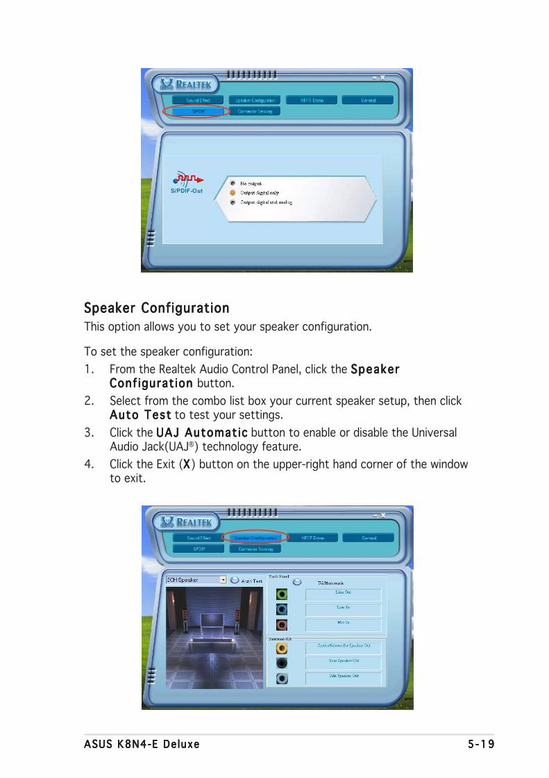
ASUS K8N4-E De luxeASUS K8N4-E De luxeASUS K8N4-E De luxeASUS K8N4-E De luxeASUS K8N4-E De luxe 5 -195 -195 -195 -195 -19
Speaker ConfigurationSpeaker ConfigurationSpeaker ConfigurationSpeaker ConfigurationSpeaker Configuration
This option allows you to set your speaker configuration.
To set the speaker configuration:
1. From the Realtek Audio Control Panel, click the SpeakerSpeakerSpeakerSpeakerSpeakerConf igurat ion Conf igurat ion Conf igurat ion Conf igurat ion Conf igurat ion button.
2. Select from the combo list box your current speaker setup, then clickAuto TestAuto TestAuto TestAuto TestAuto Test to test your settings.
3. Click the UAJ Automat icUAJ Automat icUAJ Automat icUAJ Automat icUAJ Automat ic button to enable or disable the UniversalAudio Jack(UAJ®) technology feature.
4. Click the Exit (XXXXX) button on the upper-right hand corner of the windowto exit.
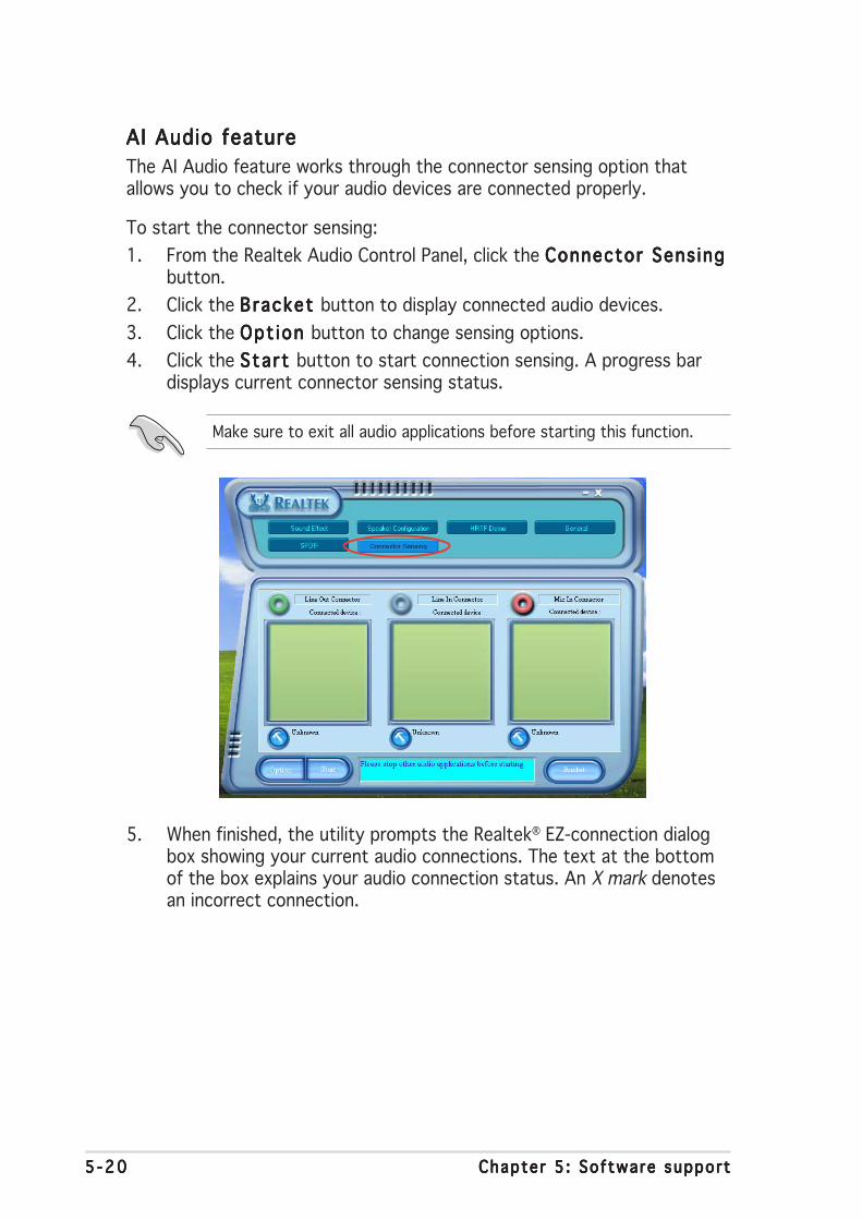
5 -205 -205 -205 -205 -20 Chapter 5 : Software supportChapter 5 : Software supportChapter 5 : Software supportChapter 5 : Software supportChapter 5 : Software support
5. When finished, the utility prompts the Realtek® EZ-connection dialogbox showing your current audio connections. The text at the bottomof the box explains your audio connection status. An X mark denotesan incorrect connection.
AI Audio featureAI Audio featureAI Audio featureAI Audio featureAI Audio feature
The AI Audio feature works through the connector sensing option thatallows you to check if your audio devices are connected properly.
To start the connector sensing:
1. From the Realtek Audio Control Panel, click the Connector Sens ingConnector Sens ingConnector Sens ingConnector Sens ingConnector Sens ingbutton.
2. Click the Bracket Bracket Bracket Bracket Bracket button to display connected audio devices.
3. Click the Opt ion Opt ion Opt ion Opt ion Opt ion button to change sensing options.
4. Click the Start Start Start Start Start button to start connection sensing. A progress bardisplays current connector sensing status.
Make sure to exit all audio applications before starting this function.

ASUS K8N4-E De luxeASUS K8N4-E De luxeASUS K8N4-E De luxeASUS K8N4-E De luxeASUS K8N4-E De luxe 5 -215 -215 -215 -215 -21
6. If there are detected problems, make sure that your audio cables areconnected to the proper audio jack and repeat connector sensing.
7. Click the X X X X X button to exit EZ-connection dialog box.
8. Click the Exit (XXXXX) button on the upper-right hand corner of the windowto exit audio control panel.
HRTF DemoHRTF DemoHRTF DemoHRTF DemoHRTF Demo
This option shows a demo of the Head-Related Transfer Functions (HRTF).
To start the HRTF demo:
1. From the Realtek Audio Control Panel, click the HRTF Demo HRTF Demo HRTF Demo HRTF Demo HRTF Demo button.
2. Click the option buttons to change the sound, moving path or EAXsettings.
3. Click the P l ay P l ay P l ay P l ay P l ay button to start or the Stop Stop Stop Stop Stop button to stop.
4. Click the Exit (XXXXX) button on the upper-right hand corner of the windowto exit.

5 -225 -225 -225 -225 -22 Chapter 5 : Software supportChapter 5 : Software supportChapter 5 : Software supportChapter 5 : Software supportChapter 5 : Software support
General settingsGeneral settingsGeneral settingsGeneral settingsGeneral settings
This option shows the audio settings and allows you to change thelanguage setting or toggle the SoundEffect icon display on the Windowstaskbar.
To display the general settings:
1. From the Realtek Audio Control Panel, click the Genera l Genera l Genera l Genera l Genera l button.
2. Click the option button to enable or disable the icon display on theWindows taskbar.
3. Click the Language Language Language Language Language combo list box to change language display.
4. Click the Exit (XXXXX) button on the upper-right hand corner of the windowto exit.

ASUS K8N4-E De luxeASUS K8N4-E De luxeASUS K8N4-E De luxeASUS K8N4-E De luxeASUS K8N4-E De luxe 5 -235 -235 -235 -235 -23
Rear panel audio ports function variationRear panel audio ports function variationRear panel audio ports function variationRear panel audio ports function variationRear panel audio ports function variation
The functions of the Line Out (lime), Line In (blue), Mic (pink), Center/Subwoofer (Yellow Orange), Rear Speaker Out (Black), and Side SpeakerOut (Gray) ports on the rear panel change when you select the 4-channel,6-channel or 8-channel audio configuration as shown in the following table.
Audio 2, 4, 6, or 8-channel configurationAudio 2, 4, 6, or 8-channel configurationAudio 2, 4, 6, or 8-channel configurationAudio 2, 4, 6, or 8-channel configurationAudio 2, 4, 6, or 8-channel configuration
Light Blue Line In Line In Line In Line In
Lime Line Out Front Speaker Out Front Speaker Out Front Speaker Out
Pink Mic In Mic In Mic In Mic In
Gray - Rear Speaker Out Rear Speaker Out Rear Speaker Out
Black - - - Side Speaker Out
Yellow Orange - - Center/Subwoofer Center/Subwoofer
P o r tP o r tP o r tP o r tP o r t H e a d s e tH e a d s e tH e a d s e tH e a d s e tH e a d s e t 4 - channe l4 - channe l4 - channe l4 - channe l4 - channe l 6 - channe l6 - channe l6 - channe l6 - channe l6 - channe l 8 - channe l8 - channe l8 - channe l8 - channe l8 - channe l2-channel2-channel2-channel2-channel2-channel

5 -245 -245 -245 -245 -24 Chapter 5 : Software supportChapter 5 : Software supportChapter 5 : Software supportChapter 5 : Software supportChapter 5 : Software support
5.3.65.3.65.3.65.3.65.3.6 Using the NVIDIAUsing the NVIDIAUsing the NVIDIAUsing the NVIDIAUsing the NVIDIA®®®®® Firewall™ Firewall™ Firewall™ Firewall™ Firewall™
The motherboard supports the NVIDIA® Firewall™ (NVFirewall™) applicationthat protects your computer from intruders. The NVFirewall™ is classifiedas a personal firewall or desktop firewall that works at the device level toprotect your system from malicious computer code by controlling theconnections to and from your computer and alerting you for attemptedintrusions. The following sections describe how to use the NVIDIA®
Firewall™.
Launching the NVFirewall™ summaryLaunching the NVFirewall™ summaryLaunching the NVFirewall™ summaryLaunching the NVFirewall™ summaryLaunching the NVFirewall™ summary
After you install the NVFirewall™ application from the motherboard supportCD, it is automatically activated with a Med ium Med ium Med ium Med ium Med ium security profile as itsdefault setting. The setup summary of NVFirewall™ is displayed in thesummary menu.
To launch the NVFirewall™ summary menu:
1. Click the NVID IANVID IANVID IANVID IANVID IA®®®®® F i rewal l™ icon F i rewal l™ icon F i rewal l™ icon F i rewal l™ icon F i rewal l™ icon fromthe Windows® taskbar.
N V I D I AN V I D I AN V I D I AN V I D I AN V I D I A®®®®® F i r ewa l l™ i con F i r ewa l l™ i con F i r ewa l l™ i con F i r ewa l l™ i con F i r ewa l l™ i con
2. Double-click the icon to displaythe NVFirewall™ Summarymenu.
C l i c k to se l ec t f i r ewa l l p ro f i l eC l i c k to se l ec t f i r ewa l l p ro f i l eC l i c k to se l ec t f i r ewa l l p ro f i l eC l i c k to se l ec t f i r ewa l l p ro f i l eC l i c k to se l ec t f i r ewa l l p ro f i l e
C l i c k to v i ew p ro f i l e de ta i l sC l i c k to v i ew p ro f i l e de ta i l sC l i c k to v i ew p ro f i l e de ta i l sC l i c k to v i ew p ro f i l e de ta i l sC l i c k to v i ew p ro f i l e de ta i l s
C l i c k to v i ew the f i r ewa l l l ogC l i c k to v i ew the f i r ewa l l l ogC l i c k to v i ew the f i r ewa l l l ogC l i c k to v i ew the f i r ewa l l l ogC l i c k to v i ew the f i r ewa l l l og
C l i c k to v i ew the f i r ewa l l s ta t sC l i c k to v i ew the f i r ewa l l s ta t sC l i c k to v i ew the f i r ewa l l s ta t sC l i c k to v i ew the f i r ewa l l s ta t sC l i c k to v i ew the f i r ewa l l s ta t s

ASUS K8N4-E De luxeASUS K8N4-E De luxeASUS K8N4-E De luxeASUS K8N4-E De luxeASUS K8N4-E De luxe 5 -255 -255 -255 -255 -25
Setting security profi lesSetting security profi lesSetting security profi lesSetting security profi lesSetting security profi les
The NVFirewall™ application allows several security profiles to match yoursystem security needs. The following describes the NVFirewall™ securityprofiles:
• L o wL o wL o wL o wL o w - allows safe incoming connections and deny those that areknown to be dangerous connections. This profile also enables someanti-hacking features.
• Med ium Med ium Med ium Med ium Med ium - blocks most incoming connections. Incoming connectionsto some ports must be set to allow file transfers using some onlinemessaging applications. This profile also enables some anti-hackingfeatures.
• H igh H igh H igh H igh H igh - allows the least traffic through. Only outbound connectionsare allowed. This profile also includes the “stealth mode’ feature thatmakes your system invisible to intruders. This also enables someanti-hacking features.
• LockdownLockdownLockdownLockdownLockdown - blocks all incoming and outgoing connections.
• Ant i -hack ing onlyAnt i -hack ing onlyAnt i -hack ing onlyAnt i -hack ing onlyAnt i -hack ing only - this profile enables all anti-hacking features butdisables the firewall. This security profile is useful if you want to use athird-party firewall application.
• Custom 1, 2, 3 Custom 1, 2, 3 Custom 1, 2, 3 Custom 1, 2, 3 Custom 1, 2, 3 - these are reserved for customized profiles.
• Of f O f f O f f O f f O f f - deactivates the firewall.
To set a security profile:
1. From the NVFirewall™ summarymenu, click the Cur rentCur rentCur rentCur rentCur rentF i rewal l Prof i leF i rewal l Prof i leF i rewal l Prof i leF i rewal l Prof i leF i rewal l Prof i le combo listbox then select a securityprofile.
The following confirmation boxappears.
2. Click Change Prof i leChange Prof i leChange Prof i leChange Prof i leChange Prof i le to applysettings or D o n ’ t C h a n g eD o n ’ t C h a n g eD o n ’ t C h a n g eD o n ’ t C h a n g eD o n ’ t C h a n g eP r o f i l eP r o f i l eP r o f i l eP r o f i l eP r o f i l e to return to previousmenu.

5 -265 -265 -265 -265 -26 Chapter 5 : Software supportChapter 5 : Software supportChapter 5 : Software supportChapter 5 : Software supportChapter 5 : Software support
Turning the NVFirewall™ offTurning the NVFirewall™ offTurning the NVFirewall™ offTurning the NVFirewall™ offTurning the NVFirewall™ off
Take caution when using this option. Your computer becomes vulnerableto viruses, hackers or intruders after you turn off the firewall.
To turn off the NVFirewall:
1. From the NVIDIA Firewallsummary menu, click theCurrent F i rewal l Prof i leCurrent F i rewal l Prof i leCurrent F i rewal l Prof i leCurrent F i rewal l Prof i leCurrent F i rewal l Prof i lecombo list box then select O f fO f fO f fO f fO f f.
The following confirmation boxappears.
2. Click Turn F i rewal l OFFTurn F i rewal l OFFTurn F i rewal l OFFTurn F i rewal l OFFTurn F i rewal l OFF.

ASUS K8N4-E De luxeASUS K8N4-E De luxeASUS K8N4-E De luxeASUS K8N4-E De luxeASUS K8N4-E De luxe 5 -275 -275 -275 -275 -27
5.3.75.3.75.3.75.3.75.3.7 Using the NVIDIAUsing the NVIDIAUsing the NVIDIAUsing the NVIDIAUsing the NVIDIA®®®®® nTune™ utility nTune™ utility nTune™ utility nTune™ utility nTune™ utility
The motherboard supports the NVIDIA® nTune™ utility that allows easy andsafe system tuning for optimum performance. This utility provides thesafest and easiest way to tweak voltages or change system bus speedsand memory timings for maximum system performance.
Follow the NVIDIA Chipset Dr iver ProgramNVIDIA Chipset Dr iver ProgramNVIDIA Chipset Dr iver ProgramNVIDIA Chipset Dr iver ProgramNVIDIA Chipset Dr iver Program installation wizard toinstall the NVIDIA® nTune™ utility from the motherboard support CD.
After you have successfully installed the utility in your computer, launchthe nTune™ utility from the Windows® desktop by clicking Start > Al lStart > Al lStart > Al lStart > Al lStart > Al lPrograms > NVIDIA Corporat ion > nTune > nTunePrograms > NVIDIA Corporat ion > nTune > nTunePrograms > NVIDIA Corporat ion > nTune > nTunePrograms > NVIDIA Corporat ion > nTune > nTunePrograms > NVIDIA Corporat ion > nTune > nTune from theWindows® taskbar.
Managing your nForce™ systemManaging your nForce™ systemManaging your nForce™ systemManaging your nForce™ systemManaging your nForce™ system
The Manage my nForce™ system menu allows you to benchmark andautomatically tune your system, manage your nTune™ profiles, monitoryour system, troubleshoot performance, create a log, get online support, orupdate the BIOS. This menu also provides shortcuts to manage yournForceware™ settings.
C l i c k to l aunch ManageC l i c k to l aunch ManageC l i c k to l aunch ManageC l i c k to l aunch ManageC l i c k to l aunch Managemy nFo rce™ sys tem menumy nFo rce™ sys tem menumy nFo rce™ sys tem menumy nFo rce™ sys tem menumy nFo rce™ sys tem menu
5 -285 -285 -285 -285 -28 Chapter 5 : Software supportChapter 5 : Software supportChapter 5 : Software supportChapter 5 : Software supportChapter 5 : Software support
Clock controlClock controlClock controlClock controlClock control
The Clock control menu allows dynamic modifications for system busspeeds and memory controller timing. The system bus speed includes thefront side bus (FSB) and AGP bus.
C l i c k to l aunch theC l i c k to l aunch theC l i c k to l aunch theC l i c k to l aunch theC l i c k to l aunch theC lock cont ro l menuC lock cont ro l menuC lock cont ro l menuC lock cont ro l menuC lock cont ro l menu
Voltage/Fan controlVoltage/Fan controlVoltage/Fan controlVoltage/Fan controlVoltage/Fan control
The Voltage/Fan control menu allows tweaking options for the CPU andmemory voltage. This menu also allows dynamic modifications for the CPUand auxiliary fan speeds.
C l i c k to l aunch theC l i c k to l aunch theC l i c k to l aunch theC l i c k to l aunch theC l i c k to l aunch theVo l t age/Fan menuVo l t age/Fan menuVo l t age/Fan menuVo l t age/Fan menuVo l t age/Fan menu

ASUS K8N4-E De luxeASUS K8N4-E De luxeASUS K8N4-E De luxeASUS K8N4-E De luxeASUS K8N4-E De luxe 5 -295 -295 -295 -295 -29
InformationInformationInformationInformationInformation
The information page displays related information about the processor,memory, motherboard, nForce™ profile, version information, and thecalculated system performance results.
Other optionsOther optionsOther optionsOther optionsOther options
Other option buttons allow you to easily save or revert your settings andsave or load nTune™ profiles.
C l i c k to l aunch theC l i c k to l aunch theC l i c k to l aunch theC l i c k to l aunch theC l i c k to l aunch theI n fo rmat i on pageI n fo rmat i on pageI n fo rmat i on pageI n fo rmat i on pageI n fo rmat i on page
C l i c k to save se t t i ngs and ex i tC l i c k to save se t t i ngs and ex i tC l i c k to save se t t i ngs and ex i tC l i c k to save se t t i ngs and ex i tC l i c k to save se t t i ngs and ex i t
C l i c k to save se t t i ngs on l yC l i c k to save se t t i ngs on l yC l i c k to save se t t i ngs on l yC l i c k to save se t t i ngs on l yC l i c k to save se t t i ngs on l y
C l i c k to r eve r t changesC l i c k to r eve r t changesC l i c k to r eve r t changesC l i c k to r eve r t changesC l i c k to r eve r t changes
C l i c k to l oad saved nTune™ p ro f i l eC l i c k to l oad saved nTune™ p ro f i l eC l i c k to l oad saved nTune™ p ro f i l eC l i c k to l oad saved nTune™ p ro f i l eC l i c k to l oad saved nTune™ p ro f i l e
C l i c k to save se t t i ngs i n a p ro f i l eC l i c k to save se t t i ngs i n a p ro f i l eC l i c k to save se t t i ngs i n a p ro f i l eC l i c k to save se t t i ngs i n a p ro f i l eC l i c k to save se t t i ngs i n a p ro f i l e

5 -305 -305 -305 -305 -30 Chapter 5 : Software supportChapter 5 : Software supportChapter 5 : Software supportChapter 5 : Software supportChapter 5 : Software support

ASUS K8N4-E De luxeASUS K8N4-E De luxeASUS K8N4-E De luxeASUS K8N4-E De luxeASUS K8N4-E De luxe 5 -315 -315 -315 -315 -31
5.4 RAID configurations
The motherboard comes with the NVIDIA® nForce4-4X chipset RAIDcontroller and the Silicon Image RAID utility that allow you to configureSerial ATA hard disk drives as RAID sets. The motherboard supports thefollowing RAID configurations.
RA ID 0RAID 0RAID 0RAID 0RAID 0 (Data striping) optimizes two identical hard disk drives to read andwrite data in parallel, interleaved stacks. Two hard disks perform the samework as a single drive but at a sustained data transfer rate, double that ofa single disk alone, thus improving data access and storage. Use of twonew identical hard disk drives is required for this setup.
RA ID 1RAID 1RAID 1RAID 1RAID 1 (Data mirroring) copies and maintains an identical image of datafrom one drive to a second drive. If one drive fails, the disk arraymanagement software directs all applications to the surviving drive as itcontains a complete copy of the data in the other drive. This RAIDconfiguration provides data protection and increases fault tolerance to theentire system. Use two new drives or use an existing drive and a new drivefor this setup. The new drive must be of the same size or larger than theexisting drive.
RAID 0+1RAID 0+1RAID 0+1RAID 0+1RAID 0+1 is data striping and data mirroring combined without parity(redundancy data) having to be calculated and written. With the RAID 0+1configuration you get all the benefits of both RAID 0 and RAID 1configurations. Use four new hard disk drives or use an existing drive andthree new drives for this setup.
RA ID 5RAID 5RAID 5RAID 5RAID 5 stripes both data and parity information across three or more harddisk drives. Among the advantages of RAID 5 configuration include betterHDD performance, fault tolerance, and higher storage capacity. The RAID 5configuration is best suited for transaction processing, relational databaseapplications, enterprise resource planning, and other business systems.Use a minimum of three identical hard disk drives for this setup.
RAID 10RAID 10RAID 10RAID 10RAID 10 is a striped configuration with RAID 1 segments whose segmentsare RAID 1 arrays. This configuration has the same fault tolerance asRAID 1, and has the same overhead for fault-tolerance as mirroring alone.RAID 10 achieves high input/output rates by striping RAID 1 segments. Insome instances, a RAID 10 configuration can sustain multiple simultaneousdrive failure. A minimum of four hard disk drives is required for this setup.
JBODJBODJBODJBODJBOD (Spanning) stands for Just a Bunch of DisksJust a Bunch of DisksJust a Bunch of DisksJust a Bunch of DisksJust a Bunch of Disks and refers to harddisk drives that are not yet configured as a RAID set. This configurationstores the same data redundantly on multiple disks that appear as a singledisk on the operating system. Spanning does not deliver any advantageover using separate disks independently and does not provide faulttolerance or other RAID performance benefits.
5 -325 -325 -325 -325 -32 Chapter 5 : Software supportChapter 5 : Software supportChapter 5 : Software supportChapter 5 : Software supportChapter 5 : Software support
5.4.15.4.15.4.15.4.15.4.1 Installing hard disksInstalling hard disksInstalling hard disksInstalling hard disksInstalling hard disks
The motherboard supports Serial ATA hard disk drives. For optimalperformance, install identical drives of the same model and capacity whencreating a disk array.
Install ing Serial ATA (SATA) hard disksInstall ing Serial ATA (SATA) hard disksInstall ing Serial ATA (SATA) hard disksInstall ing Serial ATA (SATA) hard disksInstall ing Serial ATA (SATA) hard disks
To install the SATA hard disks for a RAID configuration:
1. Install the SATA hard disks into the drive bays.
2. Connect the SATA signal cables.
3. Connect a SATA power cable to the power connector on each drive.
If you use either Windows® XP or Windows® 2000 operating system(OS), copy first the RAID driver from the support CD to a floppy diskbefore creating RAID configurations. Refer to section “5.5 Creating aRAID driver disk” for details.
• If you are creating a RA ID 0 (st r ip ing)RA ID 0 (st r ip ing)RA ID 0 (st r ip ing)RA ID 0 (st r ip ing)RA ID 0 (st r ip ing) array for performance,use two new drives.
• If you are creating a RA ID 1 (mi r ror ing) RA ID 1 (mi r ror ing) RA ID 1 (mi r ror ing) RA ID 1 (mi r ror ing) RA ID 1 (mi r ror ing) array for protection,you can use two new drives or use an existing drive and a new drive(the new drive must be of the same size or larger than the existingdrive).
• If you are creating a RA ID 0+1 RA ID 0+1 RA ID 0+1 RA ID 0+1 RA ID 0+1 array for protection, you can usefour new drives or use an existing drive and three new drives.
• If you are creating a RA ID 10RA ID 10RA ID 10RA ID 10RA ID 10 array for very high reliabilitycombined with high performance, a minimum of four disk drives isrequired.
• If you are creating a RA ID 5RA ID 5RA ID 5RA ID 5RA ID 5 configuration, use a minimum of threedisk drives; the maximum number of drives is set by controller. Useof disk drives with identical size and type is recommended.

ASUS K8N4-E De luxeASUS K8N4-E De luxeASUS K8N4-E De luxeASUS K8N4-E De luxeASUS K8N4-E De luxe 5 -335 -335 -335 -335 -33
5.4.25.4.25.4.25.4.25.4.2 NVIDIANVIDIANVIDIANVIDIANVIDIA®®®®® RAID configurations RAID configurations RAID configurations RAID configurations RAID configurations
The motherboard includes a high performance IDE RAID controllerintegrated in the NVIDIA® nForce™ 4-4X chipset. The chipset supports RAID0, RAID 1, RAID 0+1, and JBOD configurations. Use the NVIDIA® RAID utilityto configure a disk array.
Setting the BIOS RAID itemsSetting the BIOS RAID itemsSetting the BIOS RAID itemsSetting the BIOS RAID itemsSetting the BIOS RAID items
After installing the hard disk drives, make sure to set the necessary RAIDitems in the BIOS before setting your RAID configuration.
To set the BIOS RAID items:
1. Boot the system and press <Del> during the Power-On Self-Test(POST) to enter the BIOS Setup Utility.
2. From the Advanced > Onboard Devices Conf igurat ion >Advanced > Onboard Devices Conf igurat ion >Advanced > Onboard Devices Conf igurat ion >Advanced > Onboard Devices Conf igurat ion >Advanced > Onboard Devices Conf igurat ion >NVRAID Conf igurat ion NVRAID Conf igurat ion NVRAID Conf igurat ion NVRAID Conf igurat ion NVRAID Conf igurat ion menu item in the BIOS set the RA IDRA IDRA IDRA IDRA IDEnab led Enab led Enab led Enab led Enab led item to Enabled. The succeeding items becomeuser-configurable.
3. Select and enable the IDE or SATA drive(s) that you want to configureas RAID. See section “4.4.3 Onboard Devices Configuration” fordetails.
4. Save your changes and Exit Setup.
For detailed descriptions on the NVIDIA® RAID configuration, refer tothe “NVIDIA® RAID User’s Manual” found in your motherboard supportCD.

5 -345 -345 -345 -345 -34 Chapter 5 : Software supportChapter 5 : Software supportChapter 5 : Software supportChapter 5 : Software supportChapter 5 : Software support
Entering the NVIDIAEntering the NVIDIAEntering the NVIDIAEntering the NVIDIAEntering the NVIDIA®®®®® RAID uti l ity RAID uti l ity RAID uti l ity RAID uti l ity RAID uti l ity
To enter the NVIDIA® RAID utility:
1. Boot up your computer.
2. During POST, press <F10> to display the main menu of the utility.
The RAID BIOS setup screens shown in this section are for referenceonly, and may not exactly match the items on your screen.
[F6] Back [F7] Finish [TAB] Navigate [↑↓ ] Select [ENTER] Popup
At the bottom of the screen are the navigation keys. These keys allow youto move through and select menu options.
NVIDIA RAID Utility Oct 5 2004
- Define a New Array -
RAID Mode: Striping Striping Block: Optimal
Free Disks Array Disks
Loc Disk Model Name Loc Disk Model Name
1.0.M XXXXXXXXXXXXXXXXXX1.1.M XXXXXXXXXXXXXXXXXX [→] Add2.0.M XXXXXXXXXXXXXXXXXX2.1.M XXXXXXXXXXXXXXXXXX
[←] Del
Creating a RAID VolumeCreating a RAID VolumeCreating a RAID VolumeCreating a RAID VolumeCreating a RAID Volume
To create a RAID volume:
1. From the NVIDIA® RAID utility Define a New Array menu, select RA IDRA IDRA IDRA IDRA IDMode Mode Mode Mode Mode then press <Enter>. The following submenu appears.
Use the up or down arrow keys toselect a RAID mode then press<Enter>.
Mirroring
Striping
Stripe Mirroring
Spanning
ASUS K8N4-E De luxeASUS K8N4-E De luxeASUS K8N4-E De luxeASUS K8N4-E De luxeASUS K8N4-E De luxe 5 -355 -355 -355 -355 -35
T I P : T I P : T I P : T I P : T I P : For server systems, use of a lower array block size isrecommended. For multimedia computer systems used mainly for audioand video editing, a higher array block size is recommended for optimumperformance.
Take caution in using this option. All data on the RAID drives will be lost!
2. Press <TAB> select the StripingBlock then press <Enter>. Thefollowing submenu appears:
If you selected Striping or Stripe Mirroring, use the up or down arrowkeys to select the stripe size for your RAID 0 array then press<Enter>.The available values range from 8 KB to 128 KB. The defaultselection is 128 KB. The strip value should be chosen based on theplanned drive usage.
• 8 /16 KB - low disk usage
• 64 KB - typical disk usage
• 128 KB - performance disk usage
3.` Press <TAB> to select the Free Disks area. Use the left or right arrowkeys to assign the array disks.
4. Press <F7> to create RAID set. The following message box appears.
Clear disk data?
[Y] YES [N]
5. Press <Y> to clear the selected disks or <N> to proceed withoutclearing the disks. The following screen appears.
8K ↑ ↑ ↑ ↑ ↑16K32K64K128KOptim↓↓↓↓↓
5 -365 -365 -365 -365 -36 Chapter 5 : Software supportChapter 5 : Software supportChapter 5 : Software supportChapter 5 : Software supportChapter 5 : Software support
Rebuilding a RAID arrayRebuilding a RAID arrayRebuilding a RAID arrayRebuilding a RAID arrayRebuilding a RAID array
To rebuild a RAID array:
1. From the Array List menu, use the up or down arrow keys to select aRAID array then press <Enter>. The RAID Array details appear.
[Ctrl-X]Exit [↑↓↑↓↑↓↑↓↑↓ ]Select [B]Set Boot [N]New Array [ENTER]Detail
NVIDIA RAID Utility Oct 5 2004
- Array List -
Boot Id Status Vendor Array Model Name
No 4 Healthy NVIDIA MIRROR XXX.XXG
A new set of navigation keys is displayed on the bottom of thescreen.
6. Press <Ctrl+X> to save settings and exit.
[R] Rebuild [D] Delete [C] Clear Disk [ENTER] Return
Array 1 : NVIDIA MIRROR XXX.XXG
- Array Detail -
RAID Mode: Mirroring
Striping Width: 1 Striping Block: 64K
Adapt Channel M/S Index Disk Model Name Capacity
2 1 Master 0 XXXXXXXXXXXXXXXXX XXX.XXGB 1 0 Master 1 XXXXXXXXXXXXXXXXX XXX.XXGB

ASUS K8N4-E De luxeASUS K8N4-E De luxeASUS K8N4-E De luxeASUS K8N4-E De luxeASUS K8N4-E De luxe 5 -375 -375 -375 -375 -37
A new set of navigation keys is displayed on the bottom of thescreen.
2. Press <R> to rebuild a RAID array. The following screen appears.
3. Use the up or down arrow keys to select a RAID array to rebuild, thenpress <F7>. The following confirmation message appears.
[↑↓ ] Select [F6] Back [F7] Finish
Array 1 : NVIDIA MIRROR XXX.XXG
- Select Disk Inside Array -
RAID Mode: Mirroring
Striping Width: 1 Striping Block: 64K
Adapt Channel M/S Index Disk Model Name Capacity
2 1 Master 0 XXXXXXXXXXXXXXXXX XXX.XXGB 1 0 Master 1 XXXXXXXXXXXXXXXXX XXX.XXGB
Rebuild array?
[ENTER] OK [ESC] Cancel
4. Press <Enter> to start rebuilding array or press <Esc> to cancel.
5. After the rebuild process, the Array list menu appears.
5 -385 -385 -385 -385 -38 Chapter 5 : Software supportChapter 5 : Software supportChapter 5 : Software supportChapter 5 : Software supportChapter 5 : Software support
Deleting a RAID arrayDeleting a RAID arrayDeleting a RAID arrayDeleting a RAID arrayDeleting a RAID array
To delete a RAID array:
1. From the Array List menu, use the up or down arrow keys to select aRAID array then press <Enter>. The RAID Array details appear.
[R] Rebuild [D] Delete [C] Clear Disk [ENTER] Return
Array 1 : NVIDIA MIRROR XXX.XXG
- Array Detail -
RAID Mode: Mirroring
Striping Width: 1 Striping Block: 64K
Adapt Channel M/S Index Disk Model Name Capacity
2 1 Master 0 XXXXXXXXXXXXXXXXX XXX.XXGB 1 0 Master 1 XXXXXXXXXXXXXXXXX XXX.XXGB
A new set of navigation keys is displayed on the bottom of thescreen.
2. Press <D> to delete a RAID array. The following confirmation messageappears.
Delete this array?
[Y] YES [N] No
4. If you selected Yes, the Define a New Array menu appears.
Take caution in using this option. All data on the RAID drives will be lost!
3. Press <Y> to delete array or press <N> to cancel.

ASUS K8N4-E De luxeASUS K8N4-E De luxeASUS K8N4-E De luxeASUS K8N4-E De luxeASUS K8N4-E De luxe 5 -395 -395 -395 -395 -39
Clearing a disk dataClearing a disk dataClearing a disk dataClearing a disk dataClearing a disk data
To clear disk data:
1. From the Array List menu, use the up or down arrow keys to select aRAID array then press <Enter>. The RAID Array details appear.
[R] Rebuild [D] Delete [C] Clear Disk [ENTER] Return
Array 1 : NVIDIA MIRROR XXX.XXG
- Array Detail -
RAID Mode: Mirroring
Striping Width: 1 Striping Block: 64K
Adapt Channel M/S Index Disk Model Name Capacity
2 1 Master 0 XXXXXXXXXXXXXXXXX XXX.XXGB 1 0 Master 1 XXXXXXXXXXXXXXXXX XXX.XXGB
A new set of navigation keys is displayed on the bottom of thescreen.
2. Press <C> to clear disk. The following confirmation message appears.
Take caution in using this option. All data on the RAID drives will be lost!
Clear disk data?
[Y] YES [N]
5. Press <Y> to clear the disk data or press <N> to cancel.

5 -405 -405 -405 -405 -40 Chapter 5 : Software supportChapter 5 : Software supportChapter 5 : Software supportChapter 5 : Software supportChapter 5 : Software support
5.4.35.4.35.4.35.4.35.4.3 Silicon Image RAID configurationsSilicon Image RAID configurationsSilicon Image RAID configurationsSilicon Image RAID configurationsSilicon Image RAID configurations
The Silicon Image RAID controller supports RAID 0, RAID 1, RAID 10, andRAID 5 configurations. Use the Silicon Image RAID utility to configure a diskarray.
Setting the BIOS RAID itemsSetting the BIOS RAID itemsSetting the BIOS RAID itemsSetting the BIOS RAID itemsSetting the BIOS RAID items
After installing the hard disk drives, make sure to set the necessary RAIDitems in the BIOS before setting your RAID configuration.
To set the BIOS RAID items:
1. Boot the system and press <Del> during the Power-On Self-Test(POST) to enter the BIOS Setup Utility.
2. From the Advanced > Onboard Devices Conf igurat ion Advanced > Onboard Devices Conf igurat ion Advanced > Onboard Devices Conf igurat ion Advanced > Onboard Devices Conf igurat ion Advanced > Onboard Devices Conf igurat ion menuitem in the BIOS set the S i l icon Image Contro l ler S i l icon Image Contro l ler S i l icon Image Contro l ler S i l icon Image Contro l ler S i l icon Image Contro l ler item to RAIDMode. See section “4.4.3 Onboard Devices Configuration” for details.
3. Save your changes and Exit Setup.
Launching the Sil icon Image Array Management SoftwareLaunching the Sil icon Image Array Management SoftwareLaunching the Sil icon Image Array Management SoftwareLaunching the Sil icon Image Array Management SoftwareLaunching the Sil icon Image Array Management Software
Launch the Silicon Image Array Management software from Windows® XP byclicking the Sta r tSta r tSta r tSta r tSta r t button and selecting Al l Programs > S i l icon ImageAl l Programs > S i l icon ImageAl l Programs > S i l icon ImageAl l Programs > S i l icon ImageAl l Programs > S i l icon Image> Sam> Sam> Sam> Sam> Sam
• For details on the Silicon Image SATARaid™ RAID configuration, referto the “Sil3114 User’s Manual” in your motherboard support CD.
• You can only set the SATALink™ RAID 5 configuration using theSATALink™ SATA RAID Management Software.
• Make sure to install the Silicon Image SATA Link Sil 3114 driver andthe Silicon Image RAID 5 Array Management Utility from the supportCD before using RAID 5 configuration.

ASUS K8N4-E De luxeASUS K8N4-E De luxeASUS K8N4-E De luxeASUS K8N4-E De luxeASUS K8N4-E De luxe 5 -415 -415 -415 -415 -41
Entering the Sil icon Image BIOS RAID Configuration Util ityEntering the Sil icon Image BIOS RAID Configuration Util ityEntering the Sil icon Image BIOS RAID Configuration Util ityEntering the Sil icon Image BIOS RAID Configuration Util ityEntering the Sil icon Image BIOS RAID Configuration Util ity
To enter the Silicon Image BIOS RAID configuration utility:
1. Boot up your computer.
2. During POST, press <Ctrl+S> or <F4>.
The RAID BIOS setup screens shown in this section are for referenceonly, and may not exactly match the items on your screen.
The Main Menu on the upper left corner allows you to select an operationto be performed. The Main Menu options include the following:
Create RAID setCreate RAID setCreate RAID setCreate RAID setCreate RAID set - creates a new legacy RAID set or allocates spare drives.
Delete RAID set Delete RAID set Delete RAID set Delete RAID set Delete RAID set - deletes a RAID set or deallocates a spare drive.
Rebui ld RAID1 set Rebui ld RAID1 set Rebui ld RAID1 set Rebui ld RAID1 set Rebui ld RAID1 set - rebuilds a RAID 1 set (e.g. swapped drives).
Resolve Conf l icts Resolve Conf l icts Resolve Conf l icts Resolve Conf l icts Resolve Conf l icts - automatically restores disrupted drives on a RAID set.
Low Level FormatLow Level FormatLow Level FormatLow Level FormatLow Level Format - creates a pattern of reference marks on a drive.Formatting the disks erases all data previously stored in the drive.
Logica l Dr ive InfoLogica l Dr ive InfoLogica l Dr ive InfoLogica l Dr ive InfoLogica l Dr ive Info -shows the current configuration of each RAID set.
On the upper right corner of the screen is the Help message box. Themessage describes the function of each menu item. At the bottom of thescreen is the legend box. The keys on the legend box allow you to navigatethrough the setup menu options. The following lists the keys found in thelegend box and their corresponding functions.
↑↑↑↑↑ , , , , , ↓↓↓↓↓ : Select/Move to the next itemE S CE S CE S CE S CE S C : Previous MenuEnterEnte rEnte rEnte rEnte r : SelectCt r l -ECt r l -ECt r l -ECt r l -ECt r l -E : Exit
Create RAID setDelete RAID setRebuild Raid1 setResolve ConflictsLow Level FormatLogical Drive Info
RAID Configuration Utility - Silicon Image Inc. Copyright (C) 2004
↑↓↑↓↑↓↑↓↑↓ :Select Menu ESC:Previous Menu Enter:Select Ctrl-E:Exit
MAIN MENU
PHYSICAL DRIVE
0 XXXXXXXXXXX XXXXXXMB1 XXXXXXXXXXX XXXXXXMB2 XXXXXXXXXXX XXXXXXMB3 XXXXXXXXXXX XXXXXXMB
STXXXXXXXXX XXXXXXMBSTXXXXXXXXX XXXXXXMBSTXXXXXXXXX XXXXXXMBSTXXXXXXXXX XXXXXXMB
LOGICAL DRIVE
HELP
Press “Enter” to createRAID set

5 -425 -425 -425 -425 -42 Chapter 5 : Software supportChapter 5 : Software supportChapter 5 : Software supportChapter 5 : Software supportChapter 5 : Software support
Manual conf igurat ionManual conf igurat ionManual conf igurat ionManual conf igurat ionManual conf igurat ion
a. Select Manua lManua lManua lManua lManua lconf igurat ionconf igurat ionconf igurat ionconf igurat ionconf igurat ion andpress <Enter>. Thefollowing pop-up
menu appears.
b. Use the up or downarrow keys toselect a chunk sizeappropriate to yourdrive usage thenpress <Enter>.
MAIN MENU
Auto configurationManual configuration
chunk size4K8K16K32K64K128K
Creating a RAID 0 set (Striped)Creating a RAID 0 set (Striped)Creating a RAID 0 set (Striped)Creating a RAID 0 set (Striped)Creating a RAID 0 set (Striped)
To create a RAID set:
1. From the Silicon Imageconfiguration utilitymain menu, selectCreate RAID setCreate RAID setCreate RAID setCreate RAID setCreate RAID setthen press <Enter> todisplay an option menu.
2. Select RA ID 0RAID 0RAID 0RAID 0RAID 0 thenpress <Enter> todisplay the following.
3. Select your desired method of configuration.
Auto conf igurat ionAuto conf igurat ionAuto conf igurat ionAuto conf igurat ionAuto conf igurat ion
a. Select Auto Configuration the press <Enter>.
b. The utility prompts a message to input the RAID size, use the upor down arrow keys to set the RAID size then press <Enter>.
c. Press <Y> to confirm or <N> to return to the Main Menu.
MAIN MENU
Auto configurationManual configuration
By default, Auto configuration sets the stripe size to 64K and sets thelogical drives based on the physical drives installed.
MAIN MENU
Create RAID setDelete RAID setRebuild Raid1 setResolve ConflictsLow Level FormatLogical Drive Info
RAID0RAID1RAID5RAID10
SPARE DRIVEJBOD

ASUS K8N4-E De luxeASUS K8N4-E De luxeASUS K8N4-E De luxeASUS K8N4-E De luxeASUS K8N4-E De luxe 5 -435 -435 -435 -435 -43
2. Select RA ID 1RAID 1RAID 1RAID 1RAID 1 thenpress <Enter> todisplay the following.
MAIN MENU
Auto configurationManual configuration
c. The selection bar moves tothe Physical Drive menu.Using the up or down arrowkeys, select a drive thenpress <Enter> to set thefirst drive of the RAID set.
d. Repeat step c to set the second, third, and fourth drive. Thenumber of available drives depend on the installed and enabledphysical drives in the system.
e. The utility prompts a message to input the RAID size, use the upor down arrow keys to set the RAID size then press <Enter>.
f. Press <Y> to confirm or <N> to return to the Main Menu.
T I P : T I P : T I P : T I P : T I P : For server systems, use of a lower array block size isrecommended. For multimedia computer systems used mainly for audioand video editing, a higher array block size is recommended for optimumperformance.
PHYSICAL DRIVE
0 XXXXXXXXXXX XXXXXXMB1 XXXXXXXXXXX XXXXXXMB2 XXXXXXXXXXX XXXXXXMB3 XXXXXXXXXXX XXXXXXMB
Creating a RAID 1 set (Mirrored)Creating a RAID 1 set (Mirrored)Creating a RAID 1 set (Mirrored)Creating a RAID 1 set (Mirrored)Creating a RAID 1 set (Mirrored)
To create a RAID 1 set:
1. From the Silicon Imageconfiguration utilitymain menu, selectCreate RAID setCreate RAID setCreate RAID setCreate RAID setCreate RAID setthen press <Enter>. Thefollowing sub-menuappears.
MAIN MENU
Create RAID setDelete RAID setRebuild Raid1 setResolve ConflictsLow Level FormatLogical Drive Info
RAID0RAID1RAID10
SPARE DRIVE
RAID0RAID1RAID5RAID10
SPARE DRIVEJBOD

5 -445 -445 -445 -445 -44 Chapter 5 : Software supportChapter 5 : Software supportChapter 5 : Software supportChapter 5 : Software supportChapter 5 : Software support
PHYSICAL DRIVE
0 XXXXXXXXXXX XXXXXXMB1 XXXXXXXXXXX XXXXXXMB2 XXXXXXXXXXX XXXXXXMB3 XXXXXXXXXXX XXXXXXMB
c. Repeat step b to select the target drive.
d. After selecting thesource and targetdrives, the followingpop-up menuappears.
Manual conf igurat ionManual conf igurat ionManual conf igurat ionManual conf igurat ionManual conf igurat ion
a. Select Manua lManua lManua lManua lManua lconf igurat ionconf igurat ionconf igurat ionconf igurat ionconf igurat ion and press<Enter>. The selectionbar moves to the PhysicalDrives menu.
b. Using the up or down arrowkeys, select the source driveand press <Enter>.
3. Select your desired method of configuration.
Auto conf igurat ionAuto conf igurat ionAuto conf igurat ionAuto conf igurat ionAuto conf igurat ion
a. Select Auto Configuration then press <Enter>.
b. The utility prompts a message to input the RAID size, use the upor down arrow keys to set the RAID size then press <Enter>.
c. Press <Y> to confirm or <N> to return to the Main Menu.
• Auto-configuration creates a RAID 1 set without a backup copy ofthe current source disk data.
• When migrating a single hard disk drive to a RAID 1 set, use of theManual configuration is recommended.
MAIN MENU
Auto configurationManual configuration
Create with data copyCreate without data copy
• The Create w i th data copyCreate w i th data copyCreate w i th data copyCreate w i th data copyCreate w i th data copy option allows you to copy thecurrent data from the source drive to the mirror drive.
• Select Create w i th data copy Create w i th data copy Create w i th data copy Create w i th data copy Create w i th data copy if you have important data inyour source drive.
• The Create w i thout data copy Create w i thout data copy Create w i thout data copy Create w i thout data copy Create w i thout data copy option disables the disk copyfunction of the Mirrored set.
• If you selected Create w i thout data copyCreate w i thout data copyCreate w i thout data copyCreate w i thout data copyCreate w i thout data copy, the RAID 1 set mustbe repartitioned and reformatted to guarantee the consistency of itscontents.

ASUS K8N4-E De luxeASUS K8N4-E De luxeASUS K8N4-E De luxeASUS K8N4-E De luxeASUS K8N4-E De luxe 5 -455 -455 -455 -455 -45
e. If you selectedCreate with dataCreate with dataCreate with dataCreate with dataCreate with datacopycopycopycopycopy, the followingpop-up menuappears.
MAIN MENU
Auto configurationManual configuration
online copyoffline copy
The on l i ne copyon l i ne copyon l i ne copyon l i ne copyon l i ne copy option automatically copies the data to the targetdrives on the background while writing to the source drives. The o f f l i neo f f l i neo f f l i neo f f l i neo f f l i necopycopycopycopycopy option allows you to copy the contents of the source drive to thetarget drives now.
f. Use the up or down arrow keys to select desired copy method,then press <Enter>.
g. The utility prompts a message to input the RAID size, use the upor down arrow keys to set the RAID size then press <Enter>.
h. Press <Y> to confirm or <N> to return to the Main Menu.
A copy progress appears if you previously selected offline copy.
2. Select RA ID 5RAID 5RAID 5RAID 5RAID 5 thenpress <Enter> todisplay the following.
MAIN MENU
Auto configurationManual configuration
Creating a RAID 5 set (Parity)Creating a RAID 5 set (Parity)Creating a RAID 5 set (Parity)Creating a RAID 5 set (Parity)Creating a RAID 5 set (Parity)
To create a RAID 5 set:
1. From the Silicon Imageconfiguration utilitymain menu, selectCreate RAID setCreate RAID setCreate RAID setCreate RAID setCreate RAID setthen press <Enter>. Thefollowing sub-menuappears.
MAIN MENU
Create RAID setDelete RAID setRebuild Raid1 setResolve ConflictsLow Level FormatLogical Drive Info
RAID0RAID1RAID10
SPARE DRIVE
RAID0RAID1RAID5RAID10
SPARE DRIVEJBOD

5 -465 -465 -465 -465 -46 Chapter 5 : Software supportChapter 5 : Software supportChapter 5 : Software supportChapter 5 : Software supportChapter 5 : Software support
3. Select your desired method of configuration.
Auto conf igurat ionAuto conf igurat ionAuto conf igurat ionAuto conf igurat ionAuto conf igurat ion
a. Select Auto Configuration then press <Enter>.
b. The utility prompts a message to input the RAID size, use the upor down arrow keys to set the RAID size then press <Enter>.
c. Press <Y> to confirm or <N> to return to the Main Menu.
MAIN MENU
Auto configurationManual configuration
chunk size4K8K16K32K64K128K
Manual conf igurat ionManual conf igurat ionManual conf igurat ionManual conf igurat ionManual conf igurat ion
a. Select Manua lManua lManua lManua lManua lconf igurat ionconf igurat ionconf igurat ionconf igurat ionconf igurat ion andpress <Enter>. Thefollowing pop-up
menu appears.
b. Use the up or downarrow keys toselect a chunk sizeappropriate to yourdrive usage then press <Enter>.
T I P : T I P : T I P : T I P : T I P : For server systems, use of a lower array block size isrecommended. For multimedia computer systems used mainly for audioand video editing, a higher array block size is recommended for optimumperformance.
PHYSICAL DRIVE
0 XXXXXXXXXXX XXXXXXMB1 XXXXXXXXXXX XXXXXXMB2 XXXXXXXXXXX XXXXXXMB3 XXXXXXXXXXX XXXXXXMB
c. The selection bar moves tothe Physical Drive menu.Using the up or down arrowkeys, select a drive thenpress <Enter> to set thefirst drive of the RAID set.
d. Repeat step c to set the second, third and fourth drive. Thenumber of available drives depend on the installed and enabledphysical drives in the system.
e. The utility prompts a message to input the RAID size, use the upor down arrow keys to set the RAID size then press <Enter>.
f. Press <Y> to confirm or <N> to return to the Main Menu.
ASUS K8N4-E De luxeASUS K8N4-E De luxeASUS K8N4-E De luxeASUS K8N4-E De luxeASUS K8N4-E De luxe 5 -475 -475 -475 -475 -47
3. Select your desired method of configuration.
Auto conf igurat ionAuto conf igurat ionAuto conf igurat ionAuto conf igurat ionAuto conf igurat ion
a. Select Auto Configuration then press <Enter>.
b. The utility prompts a message to input the RAID size, use the upor down arrow keys to set the RAID size then press <Enter>.
c. Press <Y> to confirm or <N> to return to the Main Menu.
Auto-configuration creates a RAID 10 set without a backup copy of thecurrent source disk data.
MAIN MENU
Auto configurationManual configuration
chunk size4K8K16K32K64K128K
Manual conf igurat ionManual conf igurat ionManual conf igurat ionManual conf igurat ionManual conf igurat ion
a. Select Manua lManua lManua lManua lManua lconf igurat ionconf igurat ionconf igurat ionconf igurat ionconf igurat ion andpress <Enter>. Thefollowing pop-up
menu appears.
b. Use the up or downarrow keys toselect a chunk sizeappropriate to yourdrive usage then press <Enter>.
2. Select RA ID 10RAID 10RAID 10RAID 10RAID 10 thenpress <Enter> todisplay the following.
MAIN MENU
Auto configurationManual configuration
Creating a RAID 10 set (Mirrored+Striped)Creating a RAID 10 set (Mirrored+Striped)Creating a RAID 10 set (Mirrored+Striped)Creating a RAID 10 set (Mirrored+Striped)Creating a RAID 10 set (Mirrored+Striped)
To create a RAID 10 set:
1. From the Silicon Imageconfiguration utilitymain menu, selectCreate RAID setCreate RAID setCreate RAID setCreate RAID setCreate RAID setthen press <Enter>. Thefollowing sub-menuappears.
MAIN MENU
Create RAID setDelete RAID setRebuild Raid1 setResolve ConflictsLow Level FormatLogical Drive Info
RAID0RAID1RAID10
SPARE DRIVE
RAID0RAID1RAID5RAID10
SPARE DRIVEJBOD

5 -485 -485 -485 -485 -48 Chapter 5 : Software supportChapter 5 : Software supportChapter 5 : Software supportChapter 5 : Software supportChapter 5 : Software support
T I P : T I P : T I P : T I P : T I P : For server systems, use of a lower array block size isrecommended. For multimedia computer systems used mainly for audioand video editing, a higher array block size is recommended for optimumperformance.
PHYSICAL DRIVE
0 XXXXXXXXXXX XXXXXXMB1 XXXXXXXXXXX XXXXXXMB2 XXXXXXXXXXX XXXXXXMB3 XXXXXXXXXXX XXXXXXMB
c. The selection bar moves tothe Physical Drive menu.Using the up or down arrowkeys, select a drive thenpress <Enter> to set thefirst drive of the RAID set.
d. Repeat step c to set the second, third, and fourth drive. Thenumber of available drives depend on the installed and enabledphysical drives in the system.
• The Create w i th data copyCreate w i th data copyCreate w i th data copyCreate w i th data copyCreate w i th data copy option allows you to copy thecurrent data from the source drive to the mirror drive. The C rea teC rea teC rea teC rea teC rea tewithout data copy w i thout data copy w i thout data copy w i thout data copy w i thout data copy option disables the disk copy function of theMirrored set.
• If you selected Create w i thout data copyCreate w i thout data copyCreate w i thout data copyCreate w i thout data copyCreate w i thout data copy , the RAID 1 setmust be repartitioned and reformatted to guarantee the consistencyof its contents.
• Select Create w i th data copy Create w i th data copy Create w i th data copy Create w i th data copy Create w i th data copy if you have important data inyour source drive.
MAIN MENU
Auto configurationManual configuration
Create with data copyCreate without data copy
e. After setting theRAID drives, thefollowing pop-upmenu appears.
f. If you selectedCreate with dataCreate with dataCreate with dataCreate with dataCreate with datacopycopycopycopycopy, the followingpop-up menuappears.
MAIN MENU
Auto configurationManual configuration
online copyoffline copy

ASUS K8N4-E De luxeASUS K8N4-E De luxeASUS K8N4-E De luxeASUS K8N4-E De luxeASUS K8N4-E De luxe 5 -495 -495 -495 -495 -49
The on l i ne copyon l i ne copyon l i ne copyon l i ne copyon l i ne copy option automatically copies the data to the targetdrives on the background while writing to the source drives. The o f f l i neo f f l i neo f f l i neo f f l i neo f f l i necopycopycopycopycopy option allows you to copy the contents of the source drive to thetarget drives now.
g. Use the up or down arrow keys to select desired copy method,then press <Enter>.
h. The utility prompts a message to input the RAID size, use the upor down arrow keys to set the RAID size then press <Enter>.
i. Press <Y> to confirm or <N> to return to the Main Menu. A copyprogress appears if you previously selected offline copy.
• You can also create a RAID set using the SATARAID5 GUI utilityunder a Windows® environment.
• For details on the Silicon Image SATARaid™ RAID 5 configuration,refer to the “Sil3114 User’s Manual” found in your motherboardsupport CD.

5 -505 -505 -505 -505 -50 Chapter 5 : Software supportChapter 5 : Software supportChapter 5 : Software supportChapter 5 : Software supportChapter 5 : Software support
5.5 Creating a RAID driver disk
A floppy disk with the RAID driver is required when installing Windows®
2000/XP operating system. You can create a RAID driver disk using yourmotherboard support CD.
To create a RAID driver disk:
1. Insert the motherboard support CD into the CD-ROM drive.
2. Insert a clean floppy disk into the floppy disk drive.
3. To create an NVIDIA® RAID driver disk, click Make an Nvid iaMake an Nvid iaMake an Nvid iaMake an Nvid iaMake an Nvid iaChipset Dr iver DiskChipset Dr iver DiskChipset Dr iver DiskChipset Dr iver DiskChipset Dr iver Disk item from the Dr ivers Dr ivers Dr ivers Dr ivers Dr ivers menu.
To create a Silicon Image SATARaid™ RAID driver disk, click MakeMakeMakeMakeMakeSi l icon SATA/RAID Dr iver DiskSi l icon SATA/RAID Dr iver DiskSi l icon SATA/RAID Dr iver DiskSi l icon SATA/RAID Dr iver DiskSi l icon SATA/RAID Dr iver Disk item from the Dr ivers Dr ivers Dr ivers Dr ivers Dr ivers menu.
For additional information on RAID installation and configuration, refer tothe Manuals menu of the support CD.
4. Follow succeeding screen information to complete process.
5. Write-protect the floppy disk to avoid computer virus infection.
To install the RAID driver:
1. During the OS installation, the system prompts you to press the F 6F 6F 6F 6F 6key to install third-party SCSI or RAID driver.
2. Press <F6> then insert the floppy disk with RAID driver into the floppydisk drive.
3. Follow the succeeding screen instructions to complete the installation.
Refer to section “5.2.2 Drivers menu” for details.