k. salah 1 label switching and mpls & rsvp k. salah 2 mpls q layer 2.5 q lies between l2 and l3...
TRANSCRIPT

K. Salah 1
Label Switching and MPLS&
RSVP
K. Salah 2
MPLS Layer 2.5
Lies between L2 and L3 Packet switched network using circuit switching
technology with variable size packets Fixed size packet are mostly around 1500 bytes and do
not incur significant queuing delays MPLS is now replacing FR and ATM in the marketplace
mostly because it is better aligned with IP networks MPLS was
IP Switching by group of engineers at Ipsilon Inc. Tag Switching by Cisco Label Switching by IETF
K. Salah 3
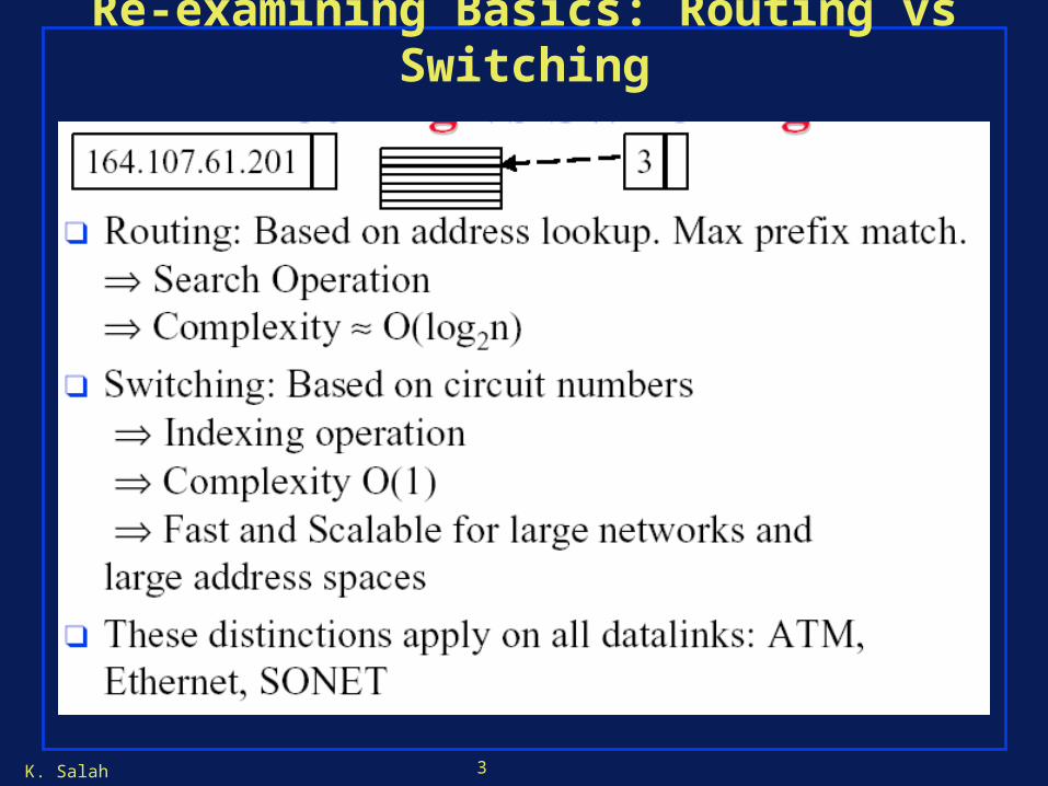
Re-examining Basics: Routing vs Switching

K. Salah 4
IP Routing vs IP Switching
K. Salah 5
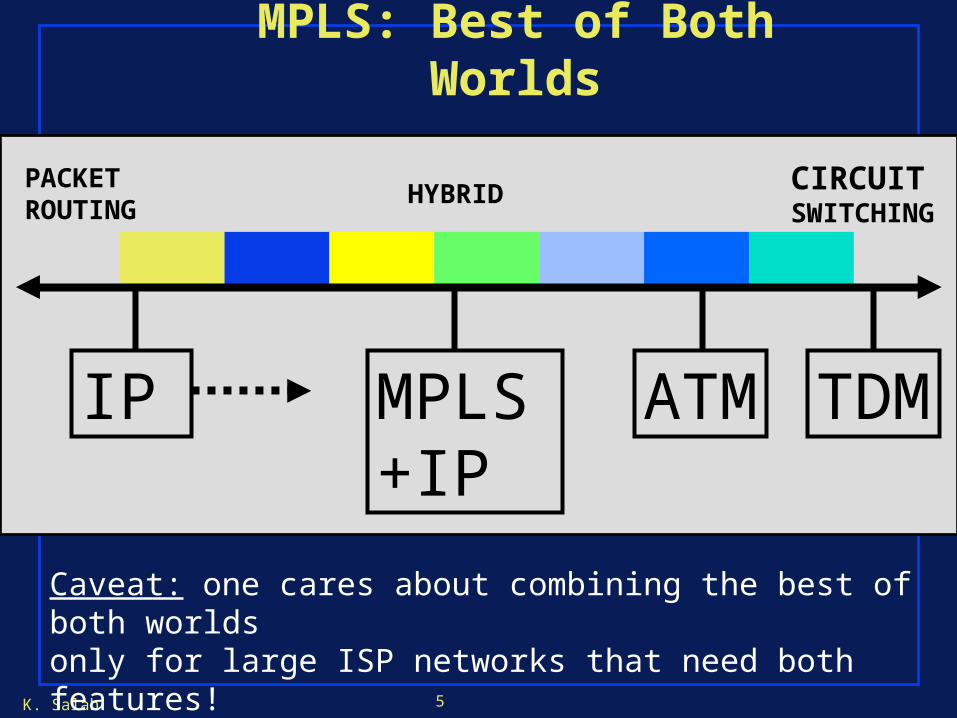
MPLS: Best of Both Worlds
PACKETROUTING
CIRCUITSWITCHING
MPLS+IP
IP ATM
HYBRID
Caveat: one cares about combining the best of both worlds only for large ISP networks that need both features!
TDM
K. Salah 6
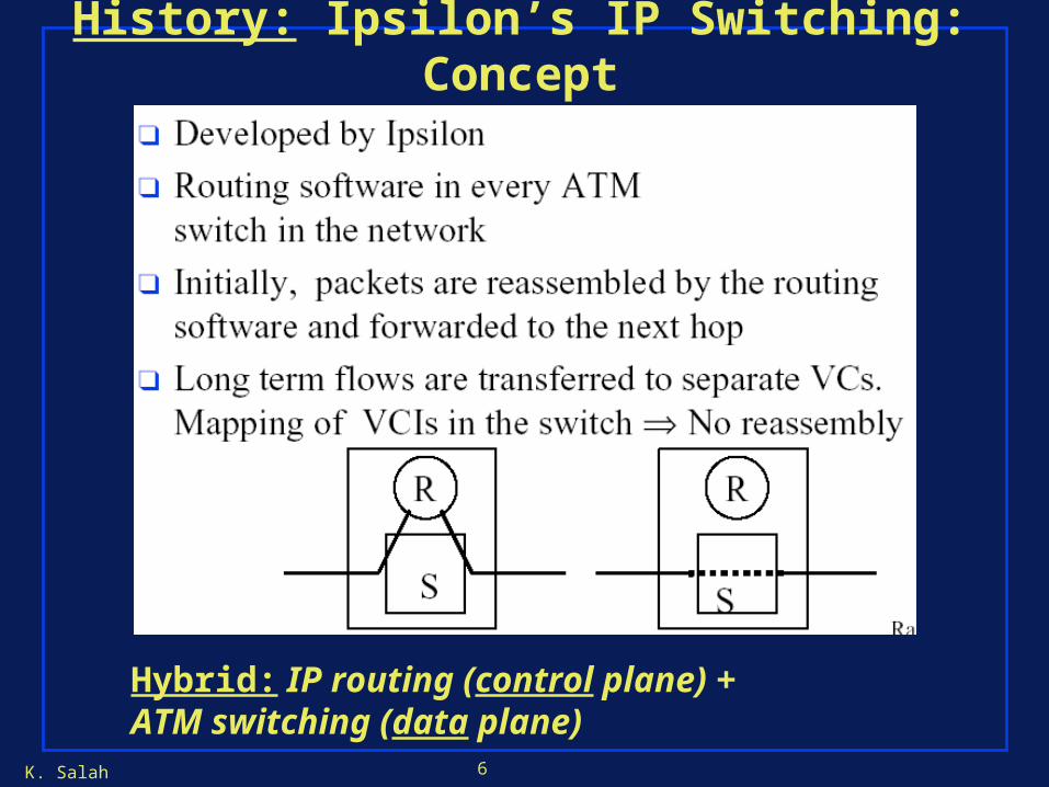
History: Ipsilon’s IP Switching: Concept
Hybrid: IP routing (control plane) + ATM switching (data plane)
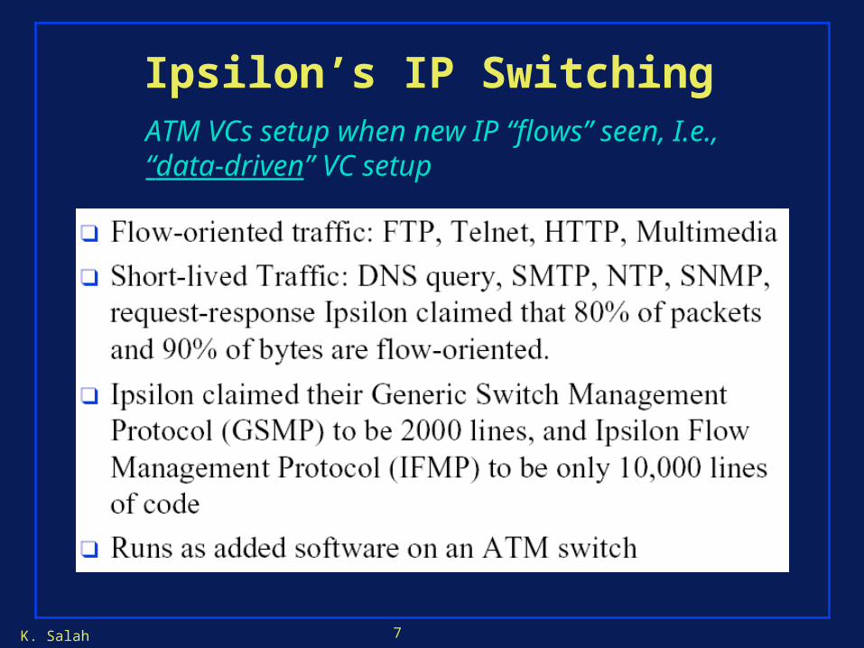
K. Salah 7
Ipsilon’s IP SwitchingATM VCs setup when new IP “flows” seen, I.e., “data-driven” VC setup
K. Salah 8
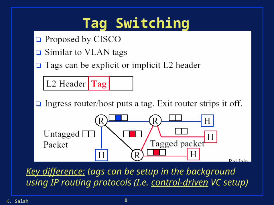
Tag Switching
Key difference: tags can be setup in the background using IP routing protocols (I.e. control-driven VC setup)

K. Salah 9
MPLS Broad Concept: Route at Edge, Switch in Core
IP ForwardingLABEL SWITCHINGIP Forwarding
IP IP #L1 IP #L2 IP #L3 IP
K. Salah 10
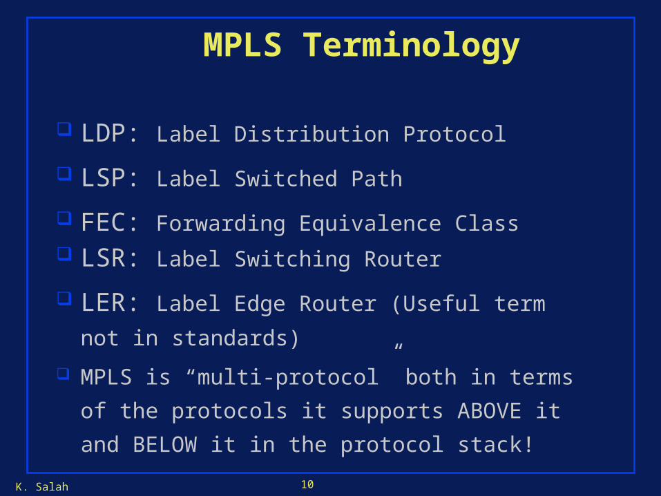
MPLS Terminology
LDP: Label Distribution Protocol
LSP: Label Switched Path
FEC: Forwarding Equivalence Class LSR: Label Switching Router
LER: Label Edge Router (Useful term not in
standards)
MPLS is “multi-protocol” both in terms of the
protocols it supports ABOVE it and BELOW it in the
protocol stack!

K. Salah 11
MPLS Header
IP packet is encapsulated in MPLS header and sent down LSP
IP packet is restored at end of LSP by egress router
…IP Packet
32-bitMPLS Header
K. Salah 12
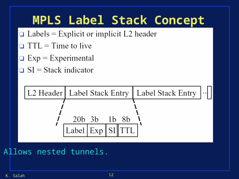
MPLS Label Stack Concept
Allows nested tunnels.
K. Salah 13
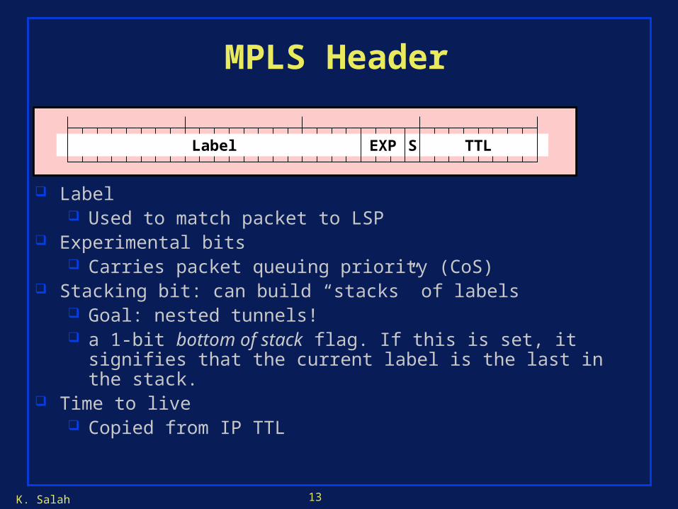
MPLS Header
Label Used to match packet to LSP
Experimental bits Carries packet queuing priority (CoS)
Stacking bit: can build “stacks” of labels Goal: nested tunnels! a 1-bit bottom of stack flag. If this is set, it signifies that the
current label is the last in the stack. Time to live
Copied from IP TTL
TTLLabel EXP S

K. Salah 14
Multi-protocol operationThe abstract notion of a “label” can be mapped to multiple circuit- or VC-oriented technologies!
• ATM - label is called VPI/VCI and travels with cell.
• Frame Relay - label is called a DLCI and travels with frame.
• TDM - label is called a timeslot its implied, like a lane.
• X25 - a label is an LCN
• Proprietary labels: TAG (in tag switching) etc..
• Frequency or Wavelength substitution where “label” is a light frequency/wavelength? (idea in G-MPLS)
K. Salah 15
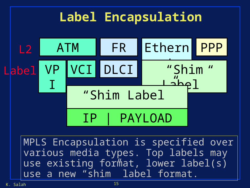
Label Encapsulation
ATM FR Ethernet PPP
MPLS Encapsulation is specified over various media types. Top labels may use existing format, lower label(s) use a new “shim” label format.
VPI VCI DLCI “Shim Label”
L2
Label
“Shim Label” …….
IP | PAYLOAD

K. Salah 16
MPLS Forwarding: Example
An IP packet destined to 134.112.1.5/32 arrives in SF San Francisco has route for 134.112/16
Next hop is the LSP to New York
SanFrancisco
New YorkIP
Santa Fe
134.112/16
134.112.1.5
19651026
0
K. Salah 17
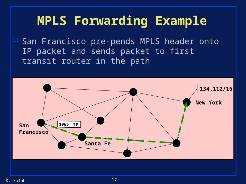
MPLS Forwarding Example
San Francisco pre-pends MPLS header onto IP packet and sends packet to first transit router in the path
SanFrancisco
New York
Santa Fe
134.112/16
IP1965

K. Salah 18
MPLS Forwarding Example Because the packet arrived at Santa Fe with an MPLS
header, Santa Fe forwards it using the MPLS forwarding table
MPLS forwarding table derived from mpls.0 switching table
SanFrancisco
New York
Santa Fe
134.112/16
IP1026

K. Salah 19
MPLS Forwarding Example
Packet arrives from penultimate router with label 0 Penultimate (i.e., next to the last)
Egress router sees label 0 and strips MPLS header Egress router performs standard IP forwarding decision
SanFrancisco
New York
Santa Fe
IP134.112/16
IP0

K. Salah 20
Label Setup/Signaling: MPLS Using IP Routing Protocols
47.1
47.247.3
Dest Out
47.1 147.2 2
47.3 3
1
23
Dest Out
47.1 147.2 2
47.3 3
Dest Out
47.1 147.2 2
47.3 3
1
23
1
2
3
• Destination based forwarding tables as built by OSPF, IS-IS, RIP, etc.

K. Salah 21
Regular IP Forwarding
47.1
47.247.3
IP 47.1.1.1
Dest Out
47.1 147.2 2
47.3 3
1
23
Dest Out
47.1 147.2 2
47.3 3
1
2
1
2
3
IP 47.1.1.1
IP 47.1.1.1IP 47.1.1.1
Dest Out
47.1 147.2 2
47.3 3
IP destination address unchanged in packet header!
K. Salah 22
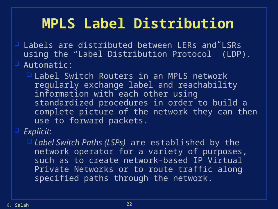
MPLS Label Distribution Labels are distributed between LERs and LSRs using the
“Label Distribution Protocol” (LDP). Automatic:
Label Switch Routers in an MPLS network regularly exchange label and reachability information with each other using standardized procedures in order to build a complete picture of the network they can then use to forward packets.
Explicit: Label Switch Paths (LSPs) are established by the
network operator for a variety of purposes, such as to create network-based IP Virtual Private Networks or to route traffic along specified paths through the network.

K. Salah 23
IntfIn
LabelIn
Dest IntfOut
3 0.40 47.1 1
IntfIn
LabelIn
Dest IntfOut
LabelOut
3 0.50 47.1 1 0.40
MPLS Label Distribution
47.1
47.247.3
1
2
31
2
1
2
3
3IntfIn
Dest IntfOut
LabelOut
3 47.1 1 0.50 Mapping: 0.40
Request: 47.1
Mapping: 0.50
Request: 47.1

K. Salah 24
Label Switched Path (LSP)
IntfIn
LabelIn
Dest IntfOut
3 0.40 47.1 1
IntfIn
LabelIn
Dest IntfOut
LabelOut
3 0.50 47.1 1 0.40
47.1
47.247.3
1
2
31
2
1
2
3
3IntfIn
Dest IntfOut
LabelOut
3 47.1 1 0.50
IP 47.1.1.1
IP 47.1.1.1

K. Salah 25
#216
#612
#5#311
#14
#99
#963
#462
- A Vanilla LSP is actually part of a tree from every source to that destination (unidirectional).
- Vanilla LDP builds that tree using existing IP forwarding tables to route the control messages.
#963
#14
#99
#311
#311
#311
A General Vanilla LSP
K. Salah 26
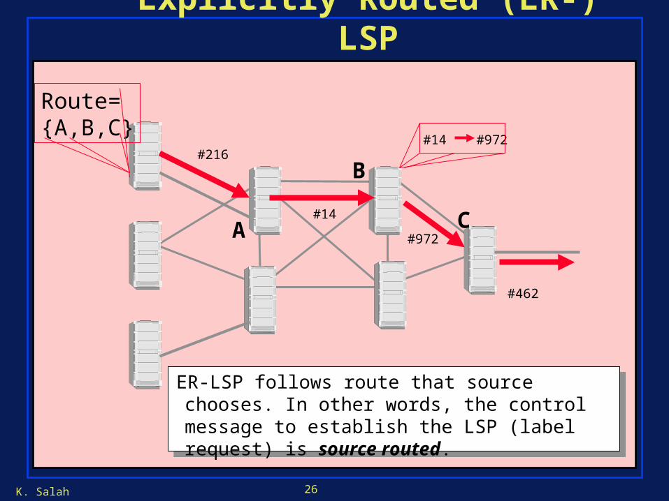
#216
#14
#462
ER-LSP follows route that source chooses. In other words, the control message to establish the LSP (label request) is source routed.
#972
#14 #972
A
B
C
Route={A,B,C}
Explicitly Routed (ER-) LSP
K. Salah 27
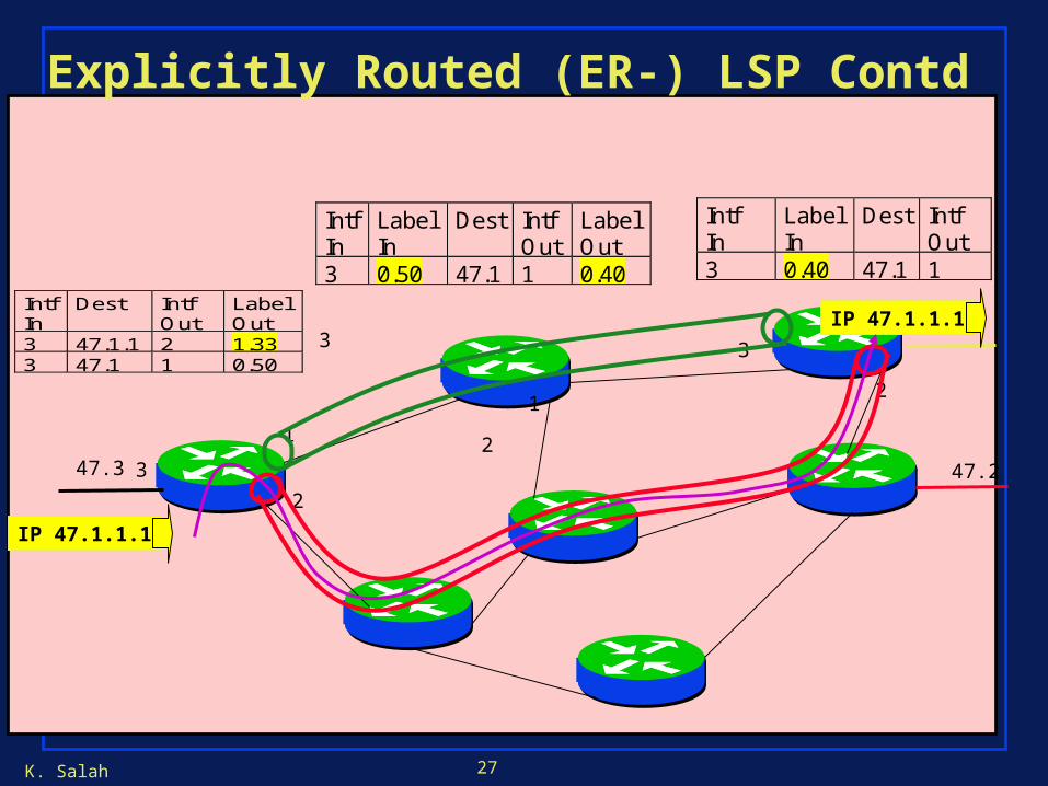
IntfIn
LabelIn
Dest IntfOut
3 0.40 47.1 1
IntfIn
LabelIn
Dest IntfOut
LabelOut
3 0.50 47.1 1 0.40
47.1
47.247.3
1
2
31
2
1
2
3
3
IntfIn
Dest IntfOut
LabelOut
3 47.1.1 2 1.333 47.1 1 0.50
IP 47.1.1.1
IP 47.1.1.1
Explicitly Routed (ER-) LSP Contd
K. Salah 28
ER LSP - advantages
•Operator has routing flexibility (policy-based, QoS-based)
•Can use routes other than shortest path
•Can compute routes based on constraints in exactly the same manner as ATM based on distributed topology database.(traffic engineering)
K. Salah 29
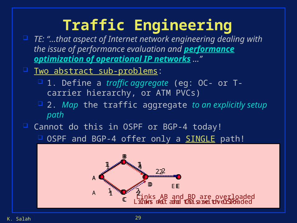
Traffic Engineering TE: “…that aspect of Internet network engineering dealing with
the issue of performance evaluation and performance optimization of operational IP networks …’’
Two abstract sub-problems: 1. Define a traffic aggregate (eg: OC- or T-carrier hierarchy,
or ATM PVCs) 2. Map the traffic aggregate to an explicitly setup path
Cannot do this in OSPF or BGP-4 today! OSPF and BGP-4 offer only a SINGLE path!
A
B
C
D
1
1 2
1
E
2
Can not do this with OSPFA
B
C
D
1
1 2
1
E
2
Links AB and BD are overloaded
A
B
C
D
1
1 2
4
E
2
Links AC and CD are overloaded

K. Salah 30
Why not TE with OSPF/BGP? Internet connectionless routing protocols designed to find only one route
(path) The “connectionless” approach to TE is to “tweak” (I.e. change) link
weights in IGP (OSPF, IS-IS) or EGP (BGP-4) protocols Limitations:
Performance is fundamentally limited by the single shortest/policy path nature:
All flows to a destination prefix mapped to the same path Desire to map traffic to different route (eg: for load-balancing
reasons) => the single default route MUST be changed Changing parameters (eg: OSPF link weights) changes routes AND
changes the traffic mapped to the routes Leads to extra control traffic (eg: OSPF floods or BGP-4 update
message), convergence problems and routing instability! Summary: Traffic mapping coupled with route availability in OSPF/BGP!
MPLS de-couples traffic trunking from path setup
K. Salah 31
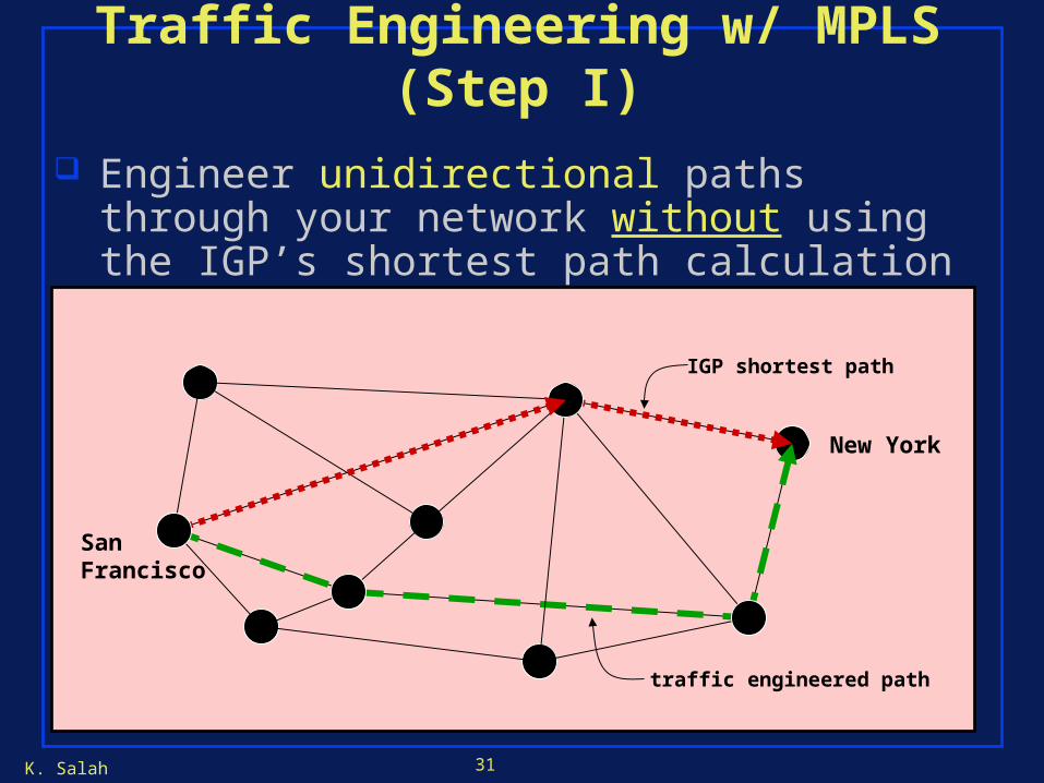
Traffic Engineering w/ MPLS (Step I)
Engineer unidirectional paths through your network without using the IGP’s shortest path calculation
SanFrancisco
IGP shortest path
traffic engineered path
New York

K. Salah 32
Traffic Engineering w/ MPLS (Part II)
IP prefixes (or traffic aggregates) can now be bound to MPLS Label Switched Paths (LSPs)
SanFrancisco
New York192.168.1/24
134.112/16
K. Salah 33
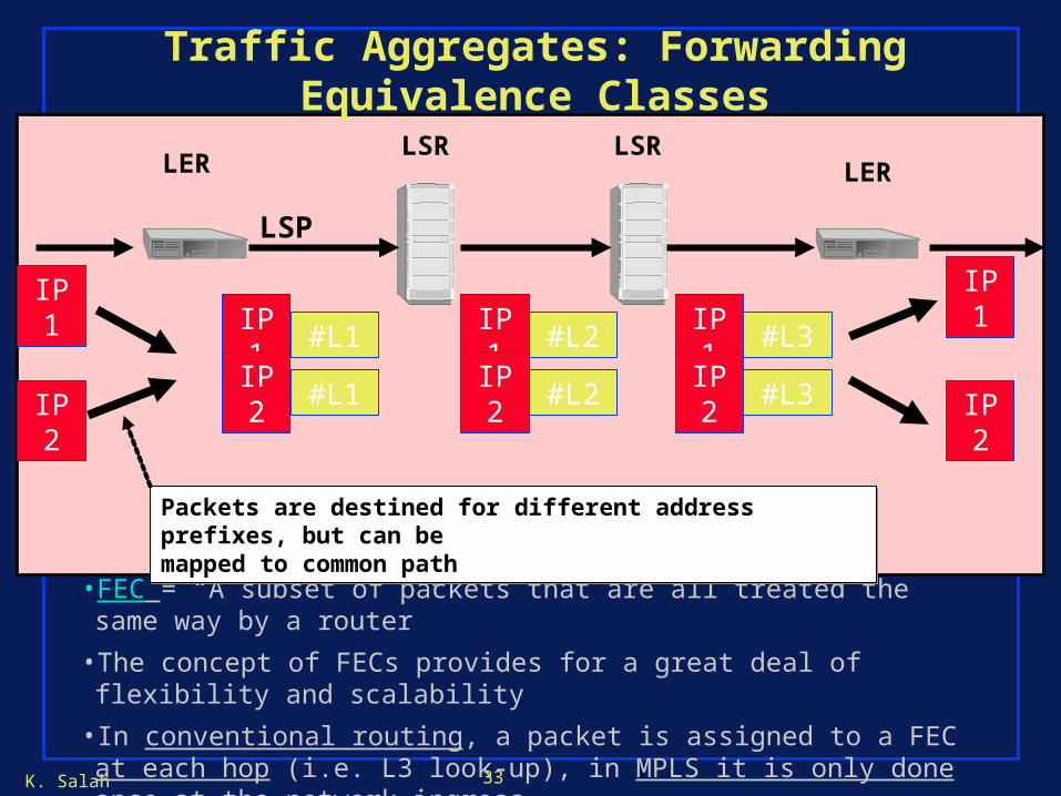
Traffic Aggregates: Forwarding Equivalence Classes
• FEC = “A subset of packets that are all treated the same way by a router”
• The concept of FECs provides for a great deal of flexibility and scalability
• In conventional routing, a packet is assigned to a FEC at each hop (i.e. L3 look-up), in MPLS it is only done once at the network ingress
Packets are destined for different address prefixes, but can bemapped to common pathPackets are destined for different address prefixes, but can bemapped to common path
IP1
IP2
IP1
IP2
LSRLSRLER LER
LSP
IP1 #L1
IP2 #L1
IP1 #L2
IP2 #L2
IP1 #L3
IP2 #L3

K. Salah 34
Signaled TE Approach (eg: MPLS) Features:
In MPLS, the choice of a route (and its setup) is orthogonal to the problem of traffic mapping onto a route
Signaling maps global IDs (addresses, path-specification) to local IDs (labels)
FEC mechanism is for defining traffic aggregates label stacking is for multi-level opaque tunneling
K. Salah 35
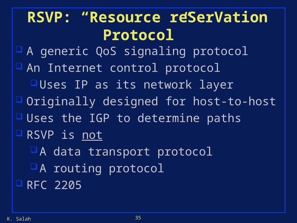
RSVP: “Resource reSerVation Protocol”
A generic QoS signaling protocol An Internet control protocol
Uses IP as its network layer Originally designed for host-to-host Uses the IGP to determine paths RSVP is not
A data transport protocolA routing protocol
RFC 2205
K. Salah 36
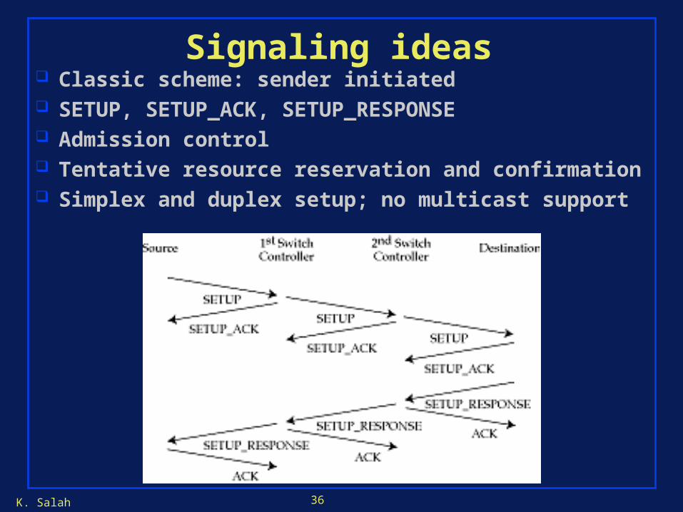
Signaling ideas Classic scheme: sender initiated SETUP, SETUP_ACK, SETUP_RESPONSE Admission control Tentative resource reservation and confirmation Simplex and duplex setup; no multicast support

K. Salah 37
RSVP: Internet Signaling Creates and maintains distributed reservation state De-coupled from routing & also to support IP multicast
model: Multicast trees setup by routing protocols, not RSVP
Key features of RSVP: Receiver-initiated: scales for multicast Soft-state: reservation times out unless refreshed
Latest paths discovered through “PATH” messages (forward direction) and used by RESV mesgs (reverse direction). Again dictated by needs of de-coupling from IP routing
and to support IP multicast model

K. Salah 38
RSVP Path Signaling Example
Signaling protocol sets up path from San Francisco to New York, reserving bandwidth along the way
PATH
Miami
Seattle
PATH
PA
TH
SanFrancisco(Ingress)
New York(Egress)

K. Salah 39
RSVP Path Signaling Example
Once path is established, signaling protocol assigns label numbers in reverse order from New York to San Francisco
SanFrancisco(Ingress)
New York(Egress)
19651026
3
Miami
Seattle
RESV
RESV
RESV
K. Salah 40
Call Admission
Session must first declare its QOS requirement and characterize the traffic it will send through the network
R-spec: defines the QOS being requested T-spec: defines the traffic characteristics A signaling protocol is needed to carry the R-spec and T-
spec to the routers where reservation is required; RSVP is a leading candidate for such signaling protocol

K. Salah 41
Call Admission
Call Admission: routers will admit calls based on their R-spec and T-spec and base on the current resource allocated at the routers to other calls.
K. Salah 42
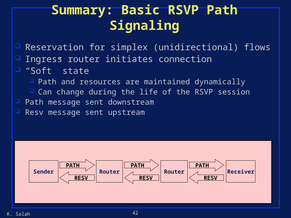
Summary: Basic RSVP Path Signaling
Sender ReceiverRouterRouter
Reservation for simplex (unidirectional) flows Ingress router initiates connection “Soft” state
Path and resources are maintained dynamically Can change during the life of the RSVP session
Path message sent downstream Resv message sent upstream
PATH
RESV
PATH
RESV
PATH
RESV
K. Salah 43
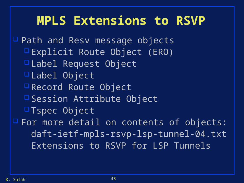
MPLS Extensions to RSVP
Path and Resv message objectsExplicit Route Object (ERO)Label Request ObjectLabel ObjectRecord Route ObjectSession Attribute ObjectTspec Object
For more detail on contents of objects:daft-ietf-mpls-rsvp-lsp-tunnel-04.txtExtensions to RSVP for LSP Tunnels

K. Salah 44
Explicit Route Object
Used to specify the explicit route RSVP Path messages take for setting up LSP
Can specify loose or strict routesLoose routes rely on routing table to find
destinationStrict routes specify the directly-connected
next router A route can have both loose and strict
components
K. Salah 45
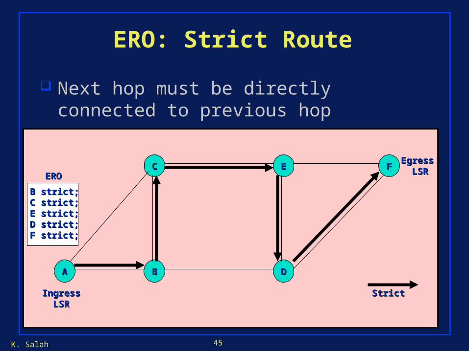
ERO: Strict Route
AA
FFEE
DD
CC
BB
IngressIngressLSRLSR
Egress Egress LSRLSR
Next hop must be directly connected to previous hop
B strict;B strict;C strict;C strict;E strict;E strict;D strict;D strict;F strict;F strict;
EROERO
StrictStrict
K. Salah 46
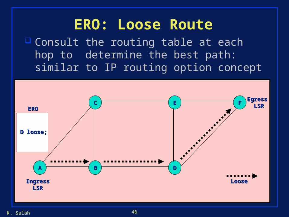
ERO: Loose Route
AA
FFEE
DD
CC
BB
Egress Egress LSRLSR
Consult the routing table at each hop to determine the best path: similar to IP routing option concept
IngressIngressLSRLSR
D loose;D loose;
EROERO
LooseLoose
K. Salah 47
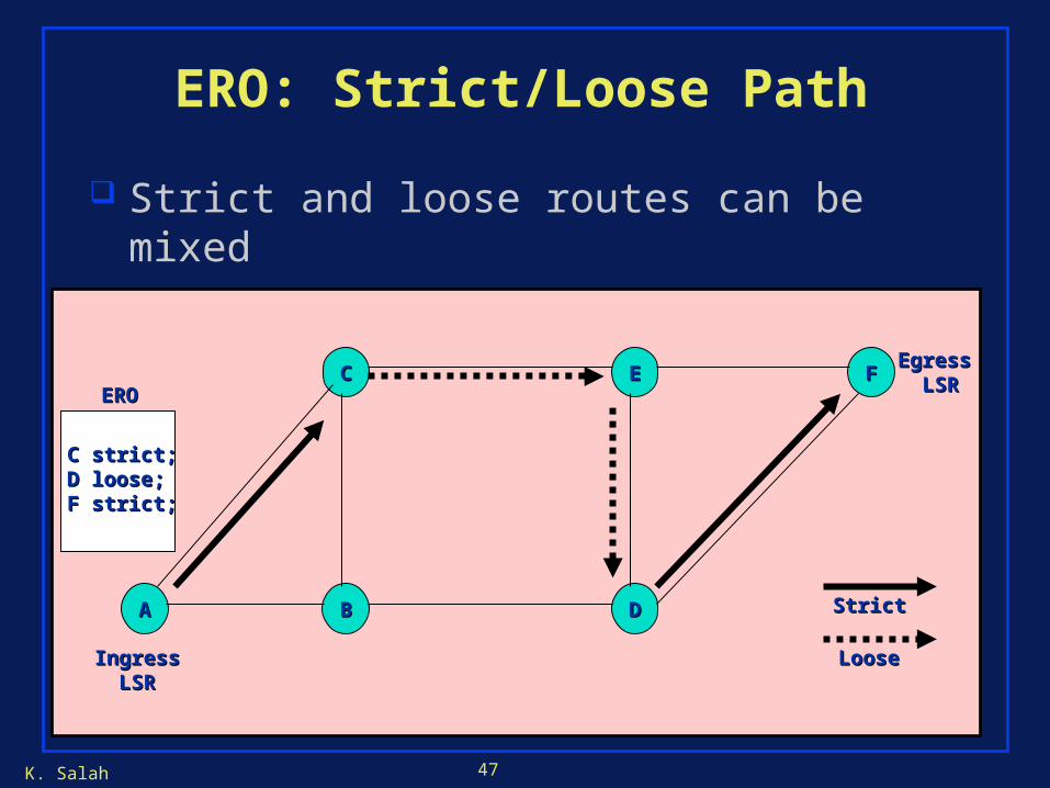
ERO: Strict/Loose Path
AA
FFEE
DD
CC
BB
Egress Egress LSRLSR
Strict and loose routes can be mixed
IngressIngressLSRLSR
C strict;C strict;D loose;D loose;F strict;F strict;
EROERO
StrictStrict
LooseLoose
K. Salah 48
RSVP Message Aggregation
Bundles up to 30 RSVP messages within single PDU
Controls Flooding of PathTear or PathErr messagesPeriodic refresh messages (PATH and RESV)
Enhances protocol efficiency and reliability Disabled by default