juliana justino de andrade - core.ac.uk · juliana justino de andrade ... escola de ciências ... i...
TRANSCRIPT
Juliana Justino de Andrade
October of 2012
Universidade do Minho
Escola de Ciências
UM
inho
|201
2Ju
liana
Jus
tino
de A
ndra
de
Self-assembled noncovalent hydrogels based on dehydrodipeptides
Se
lf-a
sse
mb
led
no
nco
vale
nt
hyd
rog
els
ba
sed
on
de
hyd
rod
ipe
pti
de
s
Juliana Justino de Andrade
October of 2012
Universidade do Minho
Escola de Ciências
This work was accomplished under the supervision of:Paula Margarida Vidigal Soares Teixeira FerreiraJosé Alberto Ribeiro Martins
Master dissertation in Medicinal Chemistry
Self-assembled noncovalent hydrogels based on dehydrodipeptides
Autora:
Juliana Justino de Andrade
E-mail: [email protected]
Dissertação de Mestrado em Ciências. Área de Conhecimento: Química Medicinal.
Título: Hidrogéis preparados a partir da automontagem de desidrodipéptidos.
Ano de Publicação: 2012.
Orientadores:
Paula Margarida Vidigal Soares Teixeira Ferreira.
José Alberto Ribeiro Martins.
É AUTORIZADA A REPRODUÇÃO PARCIAL DESTA TESE APENAS PARA EFEITOS
DE INVESTIGAÇÃO, MEDIANTE DECLARAÇÃO ESCRITA DO INTERESSADO, QUE A TAL SE
COMPROMETE;
Universidade do Minho, ___/___/______
Assinatura: ________________________________________________

This work was supported by:

“A felicidade aparece para aqueles que choram. Para aqueles que se machucam. Para
aqueles que buscam e tentam sempre. E para aqueles que reconhecem a importância das
pessoas que passam por suas vidas.”
Clarice Lispector

v
Acknowledgements
I would like to thank my supervisors Paula Margarida Ferreira and José Alberto Martins
for all the support during the development of this work. I definitely will keep a special
place for them in my heart and will remember all the lessons taught by them.
I am grateful to the Chemistry Department and Chemistry Center of the University of
Minho for providing the technical and human conditions that made this work possible.
I take special pleasure in acknowledge Professor Rui Brito from the Department of
Chemistry, University of Coimbra, for providing the conditions for the CD study.
I really owe sincere thankfulness to my laboratory colleagues Goreti and Helena who
helped me with important discussions about the work and with some procedures that
were crucial for having all work done successfully.
To my department friends Janaina, Alexandra, Raquel, Gonçalo and António I offer my
gratitude for all special moments spent together and for receiving me open heartily
during my mobility. These fellows really made it easier to accomplish this work and
gave me courage to overcome difficulties.
I am truly indebted and thankful to my special friends Ana Luisa Rodrigues and Jorge
Manuel Ferreira that were like rocks to me and with whom I could count during all my
stay in Portugal. They are angels that appeared to light my way and to make my journey
less arduous.
Finally, but not less relevant, I would like to thank my parents, my sister, my family
and brazilian friends that always believed me and gave all the love and strength I
needed to carry on following my dreams, mainly in the most difficult moments.
vi
Abstract
Self-assembly of nanometric structures from molecular building blocks is an effective
way to make new functional materials for biological and technological applications.
In this work we synthesized new N-modified dehydrodipeptides based on phenylalanine
and dehydroamino acid units attached to aromatic modifiers, namely trimesoyl,
terephtaloyl, diphenylacetyl and 2,2´-(1,3-phenylene)diacetyl in a pattern that afforded
mono or polysubstitued organic molecules. The potential use of these new compounds
as hydrogelators was evaluated. The results showed that most of the prepared
compounds behave as efficient molecular hydrogelators forming hydrogels at minimum
gelation concentrations of 0.3-0.8 wt%.
Two new compounds failed to form hydrogels probably due to unfavorable
thermodynamic contribution of intermolecular interactions.
The self-aggregation pattern of the hydrogelators was investigated by STEM
microscopy technique, revealing different shapes depending on the N-aromatic moiety.
A circular dichroism analysis was also performed in order to evaluate if the peptides
aggregate into any characteristic secondary structure, usually found in protein folding.
We found that the 5 hydrogelators had characteristic signals, demonstrating the presence
of organized structures even below the minimum gelation concentration. At elevated pH
or for the non-hydrogelating compounds, it was not observed signals indicative of the
presence of such structures.
Keywords: hydrogels; hydrogelators; dehydrodipeptides; dehydroamino acids.
vii
Resumo
A automontagem de estruturas manométricas, a partir de entes de dimensão molecular,
consiste em uma alternativa eficiente para a síntese de novos materiais funcionais para
aplicações biotecnológicas.
Neste trabalho, foram sintetizados novos desidrodipéptidos modificados em sua porção
N-terminal. Os dipéptidos continham fenilalanina e desidroaminoácidos e os grupos
modificadores foram grupos aromáticos (trimesoil, tereftaloil, difenilacetil e o 2,2´-(1,3-
phenileno)diacetil) os quais foram conjugados de forma a gerar compostos mono ou
polissubstituídos. A capacidade de gelificar em meio aquoso, destes novos compostos,
foi avaliada e os resultados mostraram que a maioria deles conseguiram gelificar em
meio aquoso em concentrações mínimas na faixa 0.3-0.8 m%.
Dois destes compostos não conseguiram originar hidrogéis, provavelmente devido a um
balanço termodinamicamente desfavorável das interacções intermoleculares entre os
constituintes do sistema.
O padrão morfológico resultante da auto-agregação dos compostos que geraram os
hidrogéis foi investigado pela técnica de microscopia electrónica de transmissão por
scaneamento (STEM). Esta análise revelou que houve a ocorrência de diferentes tipos
de estruturas nos hidrogéis, dependendo de qual modificador aromático foi utilizado.
Também realizou-se uma análise de Dicroísmo Circular para avaliar se os péptidos
agregavam-se em algum padrão de estrutura secundária característica de enovelamento
proteico. Detectou-se que nos 5 agentes gelificates haviam sinais característicos da
presença de estruturas organizadas mesmo abaixo da concentração de gelificação
mínima. Em pH elevado e nas moléculas não gelificantes, não se observam sinais
indicativos da presença deste tipo de estruturas.
Palavras-chave: hidrogéis; desidro-aminoácidos; desidrodipéptidos.
viii
Table of contents
Acknowledgements ........................................................................................................... v
Abstract ........................................................................................................................... vii
Resumo .......................................................................................................................... viii
Table of contents ............................................................................................................. ix
List of abbreviations and symbols .................................................................................. xii
List of Illustrations ........................................................................................................ xiv
List of Tables ................................................................................................................. xvi
1. Introduction ................................................................................................................... 1
1.1 Gels and Hydrogels ............................................................................................ 1
1.2 Classification of hydrogels. ................................................................................ 3
1.3 LMWGs and self-assembly process ..................................................................... 4
1.4 Design of LMWGs ............................................................................................... 6
1.5 Methods for the characterization of hydrogels ................................................... 15
2. Objectives .................................................................................................................... 21
3. Results and discussions ............................................................................................... 23
3.1 Synthesis of the modified α,β-insaturated peptides .......................................... 23
3.2 Synthesis of the dehydropeptides ............................................................................ 24
3.3 Peptide coupling to the aromatic modifiers ............................................................ 27
3.4 Attempt to reach the final compounds bearing the catecholamine derivatives
(25) and (27) ............................................................................................................ 35
3.5 Hydrogel preparation .......................................................................................... 39
3.6 Characterization of hydrogels ............................................................................ 41
3.6.1 Scanning transmission electron microscopy (STEM) ................................... 41
3.6.2 Circular dichroism analysis .............................................................................. 45
4. Conclusions and future perspectives ........................................................................... 47
5. Experimental section ................................................................................................... 48
5.1 Synthesis of dehydroamino acid derivatives 8a and 8b ................................... 49
ix
5.1.1 Synthesis of H-L-Thr-OMe·HCl (3a): ........................................................ 49
5.1.2 Synthesis of H-DL-Phe(β-OH)-OMe·HCl (3b) .......................................... 49
5.1.3 Synthesis of Boc-L-Phe-OH (4) ................................................................ 50
5.1.4 Synthesis of Boc-L-Phe-L-Thr-OMe (6a) .................................................. 51
5.1.5 Synthesis of Boc-L-Phe-DL-Phe(β-OH)-OMe (6b) .................................. 51
5.1.6 Synthesis of Boc-L-Phe-∆Abu-OMe (7a) ................................................. 52
5.1.7 Synthesis of Boc-L-Phe-∆Phe-OMe (7b) .................................................. 53
5.1.8 Synthesis of H-L-Phe-Z-∆Abu-OMe,TFA (8a) ........................................ 53
5.1.9 Synthesis of H-L-Phe-Z-∆Phe-OMe,TFA (8b) ......................................... 54
5.2 Coupling of the dehydrodipeptides to the organic modifiers .............................. 54
5.2.1 Synthesis of compound 13a ....................................................................... 54
5.2.2 Synthesis of compound 13b ........................................................................ 55
5.2.3 Synthesis of compound 14a ....................................................................... 56
5.2.4 Synthesis of compound 14b ....................................................................... 57
5.2.5 Synthesis of compound 15 .......................................................................... 57
5.2.5.1 Method 1 ..................................................................................... 57
5.2.5.1.1 Synthesis of 22 ............................................................. 58
5.2.5.1.2 Synthesis of 23 ............................................................. 59
5.2.5.1.3 Dehydration of 23 ......................................................... 59
5.2.5.2 Method 2 ..................................................................................... 60
5.2.6 Synthesis of compound 16a ........................................................................ 61
5.2.7 Synthesis of compound 16b ........................................................................ 61
5.2.8 Synthesis of compound 24 .......................................................................... 62
x
5.2.8.1 Acetylation of the caffeic acid (CA) ........................................... 62
5.2.8.2 Coupling of the diacetylated caffeic acyl chloride to the
dehydrodipeptide 8b ............................................................................................ 63
5.2.9 Synthesis of compound 26 .......................................................................... 64
5.2.9.1 Acetylation of the dihydrocaffeic acid (DHCA) ........................ 64
5.2.9.2 Coupling of the diacetylated dihydrocaffeic acyl chloride to the
dehydrodipeptide 8b ............................................................................................ 64
5.3 Basic hydrolysis of the methyl esters ................................................................ 65
5.3.1 Synthesis of compound 17a ....................................................................... 66
5.3.2 Synthesis of compound 17b ....................................................................... 66
5.3.3 Synthesis of compound 18a ....................................................................... 67
5.3.4 Synthesis of compound 18b ....................................................................... 67
5.3.5 Synthesis of compound 19 .......................................................................... 68
5.3.6 Synthesis of compound 20a ....................................................................... 68
5.3.7 Synthesis of compound 20b ....................................................................... 69
6. Bibliography ................................................................................................................ 70
xi
List of Abbreviations and Symbols
% Percentage °C Celsius degrees 2D Bidimensional 3D Tridimensional aa Amino acid Abs Absorvance Abu Aminobutyric acid ACN Acetonitrile Ar Aromatic Boc tert-butylcarbonyl
Boc2O Di-tert-butyl dicarbonate
br. s broad singlet CD circular dichroism
CDCl3 Deuterated chloroform
cgc Critical gelation concentration
CH2Cl2 Dichloromethane
d Doublet DCC Dicyclohexylcarbodiimide dd double doublet DHD Dehydrodipeptide DMAP 4-dimethylaminopyridine
DMF Dimethylformamide
DMSO-d6 deuterated dimethylsulfoxide
Fmoc 9-fluorenylmethoxycarbonyl g Grams G´ storage modulus G´´ loss modulus Gly Glycine h Hours HMBC Heteronuclear Multiple Bond Coherence HOBt Hydroxybenzotriazole HSQC Heteronuclear Multiple Quantum Coherence Hz Hertz J coupling constant LMWGs Low molecular weight gelators m Multiplet m Meta
M Molar (mmol/mL) m.p. melting point
xii
mg Miligrams MHz Megahetz min Minutes mL Mililitre mmol Milimol Nap Naphtalene NHS N-hydroxysucinimide nm Nanometer NMR Nuclear magnetic resonance 13C-NMR Nuclear magnetic resonance of 13C 1H-NMR Nuclear magnetic resonance of 1H
o Ortho
p Para
pH Hydrogenionic potencial Phe Phenylalanine ppm Parts per million q Quartet r.t. Room temperature s Singlet STEM Scanning electron microscopy t Triplet TEA Triethylamine TFA trifluoracetic acid THF Tetrahydrofurane Thr Threonine t.l.c Thin layer chromatography TMG N,N,N,N’ – tetramethylguanidine
UV Ultraviolet Val Valine δ Chemical shift ∆Abu Dehydroaminobutyric acid ∆Phe Dehydrophenylalanine µm Micrometer
xiii
List of Illustrations
Figure 1 Data retrieved from Web of science with the search “Self-Assembled Low Molecular Weight Hydrogels” - until June of 2012. ........................................................ 1 Figure 2 Log-log plot of storage modulus, G'(ω), and loss modulus, G"(ω), versus angular frequency for a 13.9% (w/w) solution of polystyrene in di(2-ethylhexyl) phthalate ........................................................................................................ 2 Figure 3 Schematic representation of different aggregation modes for peptide-based molecular hydrogelators. .................................................................................................. 6 Figure 4 Series of hierarchical structures based on β-sheet fibres depending on the concentration. ................................................................................................................... 7 Figure 5 β-harpin structure: (A) peptidic sequence; (B) cartoon scheme of the β-harpin turn .................................................................................................................................... 8 Figure 6 Schematic representation of a dimeric coiled-coil ............................................ 9 Figure 7 (A) Basic overall chemical structure of a peptide amphiphile. (B) Cartoon representation showing the supramolecular arrangement of the peptide amphiphiles ..... 9 Figure 8 Schematic diagram of nanotube assembly from cyclic D,L-peptides ............. 10 Figure 9 Chemical structure of one amphiphile peptide synthesized by Hartgerink et al
........................................................................................................................................ 11 Figure 10 Molecular modeling of the structures formed from the peptides with negatively charged heads and glycine tail ...................................................................... 11 Figure 11 Peptide RADA16-I: amino acid sequence and molecular model of RADA16-I ....................................................................................................................................... 12 Figure 12 Examples of π-stacking inducing groups frequently employed in the synthesis of hydrogelators. ............................................................................................. 13 Figure 13 CD spectra of poly-L-lysine and placental collagen. .................................. 16 Figure 14 Class of C2-symmetric compounds synthesized in this work as potential hydrogelators. ................................................................................................................. 19 Figure 15 Class of C3-symmetric compounds synthesized in this work as potential hydrogelators. ................................................................................................................. 19 Figure 16 DHD monosustitued derivatives containing diphenylacetyl N-capping organic modifiers, synthesized in this work as potential hydrogelators. ........................ 20 Figure 17 Chemical structure of dihydrocaffeic acid (DHCA) and caffeic acid (CA) molecules used as organic modifiers in this work. ......................................................... 20 Figure 18 Mechanism for the DMF-catalyzed conversion of the carboxylic acid functional group into an acyl chloride via the Vilsmeier-Haack intermediate. .............. 30 Figure 19 1H-NMR (400MHz) spectrum of compound 13b in DMSO......................... 33 Figure 20 1H NMR (400 MHz) spectrum of compound 20a in DMSO. ....................... 34 Figure 21 1H NMR (400 MHz, DMSO) spectrum for compound 19 with added TFA. 35 Figure 22 1H-NMR (400 MHz, DMSO) spectrum for compound 24............................ 36 Figure 23 1H NMR (400 MHz, DMSO) spectrum for compound 26. ........................... 37
xiv
Figure 24 HRMS (ESI positive ionization) for the product obtained in the hydrolysis of compound 24. ................................................................................................................. 38 Figure 25 HRMS (ESI, positive ionization) for the product obtained in the hydrolysis of the compound 27. ........................................................................................................... 38 Figure 26 Structures of the modified peptides that were hydrogelators under the tested conditions. ...................................................................................................................... 39 Figure 27 Hydrogels formed by hydrogelators 17b (A), 18a (B), 19 (C), 20a (D) and 20b (E). ........................................................................................................................... 41 Figure 28 STEM images of the hydrogels formed by compounds 17b, 18a, 19, 20a and 20b. ................................................................................................................................. 42 Figure 29 Reversible transition between peptide nanotubes and vesicle-like structure. 44 Figure 30 CD spectra of hydrogelators 17a, 17b, 18a, 8b, 19, 20a and 20b; hydrogelator 17b at pH 6 , hydrogelator 17b at pH 12, hydrogel of compound 17b .... 45
Scheme 1 Schematic diagram for (A) polymeric hydrogel and (B) molecular hydrogel. 4 Scheme 2 Chemical structures of the synthesized dehydrodipeptide derivatives. ......... 21 Scheme 3 Caffeic acid (25) and dihydrocaffeic acid (27) peptide derivatives designed in this work as potential hydrogelators. .............................................................................. 22 Scheme 4 Overview of the synthetic methodology employed for the synthesis of potential dehydropeptide hydrogelators. ........................................................................ 23 Scheme 5 Retrosynthetic analysis for the synthesis of the dehydrodipeptides Boc-L-Phe-Z-∆Abu-OMe (8a) and Boc-L-Phe-Z-∆Phe-OMe (8b). ......................................... 24 Scheme 6 Activation of the carboxylic acid group with a carbodiimide reagent and possible side reactions. ................................................................................................... 26 Scheme 7 Mechanism for the DCC/HOBt coupling reaction. ....................................... 26 Scheme 8 Structure of the compounds obtained from the coupling reaction of 8a and 8b with organic modifiers. Isolated yields (%) are also indicated....................................... 28 Scheme 9 Synthetic route to compound 15. ................................................................... 31 Scheme 10 Mechanism of DCC/NHS coupling. ............................................................ 31 Scheme 11 Synthetic route for the coupling of dehydropeptide 8b with caffeic acid (CA) and dihydocaffeic acid (DHCA) leading to the compounds 24 and 26................. 36 Scheme 12 Representation of the spherical packing hypothesis for compound 19. The formation of spheres may result from closure of the sheet along two axes.................... 43
xv
List of tables
Table 1 Study of the effect of solvents on the isolated yield of the coupling reaction between organic modifiers 9 and 10 and dehydrodipeptides 8a and 8b. ....................... 29 Table 2 Critical gelation concentration (wt%) and the pH of the resulting hydrogels. . 39
1
1. Introduction
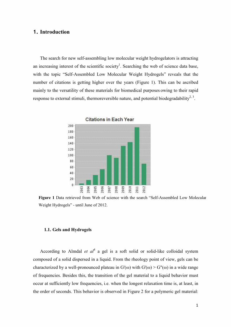
The search for new self-assembling low molecular weight hydrogelators is attracting
an increasing interest of the scientific society1. Searching the web of science data base,
with the topic “Self-Assembled Low Molecular Weight Hydrogels” reveals that the
number of citations is getting higher over the years (Figure 1). This can be ascribed
mainly to the versatility of these materials for biomedical purposes owing to their rapid
response to external stimuli, thermoreversible nature, and potential biodegradability2, 3.
1.1. Gels and Hydrogels
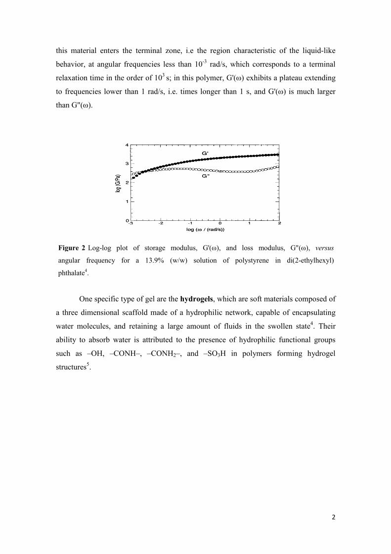
According to Almdal et al4 a gel is a soft solid or solid-like colloidal system
composed of a solid dispersed in a liquid. From the rheology point of view, gels can be
characterized by a well-pronounced plateau in G'(ω) with G'(ω) > G"(ω) in a wide range
of frequencies. Besides this, the transition of the gel material to a liquid behavior must
occur at sufficiently low frequencies, i.e. when the longest relaxation time is, at least, in
the order of seconds. This behavior is observed in Figure 2 for a polymeric gel material:
Figure 1 Data retrieved from Web of science with the search “Self-Assembled Low Molecular
Weight Hydrogels” - until June of 2012.
2
this material enters the terminal zone, i.e the region characteristic of the liquid-like
behavior, at angular frequencies less than 10-3 rad/s, which corresponds to a terminal
relaxation time in the order of 103 s; in this polymer, G'(ω) exhibits a plateau extending
to frequencies lower than 1 rad/s, i.e. times longer than 1 s, and G'(ω) is much larger
than G"(ω).
One specific type of gel are the hydrogels, which are soft materials composed of
a three dimensional scaffold made of a hydrophilic network, capable of encapsulating
water molecules, and retaining a large amount of fluids in the swollen state4. Their
ability to absorb water is attributed to the presence of hydrophilic functional groups
such as –OH, –CONH–, –CONH2–, and –SO3H in polymers forming hydrogel
structures5.
Figure 2 Log-log plot of storage modulus, G'(ω), and loss modulus, G"(ω), versus
angular frequency for a 13.9% (w/w) solution of polystyrene in di(2-ethylhexyl)
phthalate4.
3
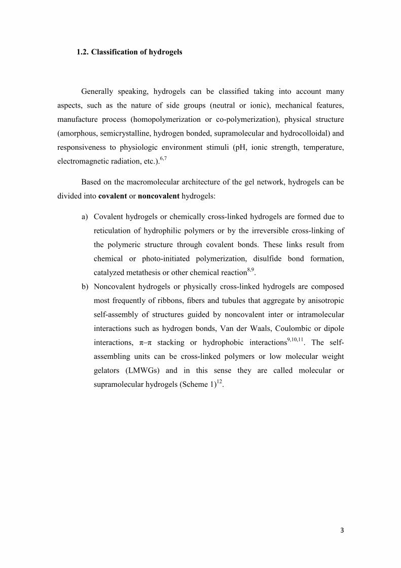
1.2. Classification of hydrogels
Generally speaking, hydrogels can be classified taking into account many
aspects, such as the nature of side groups (neutral or ionic), mechanical features,
manufacture process (homopolymerization or co-polymerization), physical structure
(amorphous, semicrystalline, hydrogen bonded, supramolecular and hydrocolloidal) and
responsiveness to physiologic environment stimuli (pH, ionic strength, temperature,
electromagnetic radiation, etc.).6,7
Based on the macromolecular architecture of the gel network, hydrogels can be
divided into covalent or noncovalent hydrogels:
a) Covalent hydrogels or chemically cross-linked hydrogels are formed due to
reticulation of hydrophilic polymers or by the irreversible cross-linking of
the polymeric structure through covalent bonds. These links result from
chemical or photo-initiated polymerization, disulfide bond formation,
catalyzed metathesis or other chemical reaction8,9.
b) Noncovalent hydrogels or physically cross-linked hydrogels are composed
most frequently of ribbons, fibers and tubules that aggregate by anisotropic
self-assembly of structures guided by noncovalent inter or intramolecular
interactions such as hydrogen bonds, Van der Waals, Coulombic or dipole
interactions, π–π stacking or hydrophobic interactions9,10,11. The self-
assembling units can be cross-linked polymers or low molecular weight
gelators (LMWGs) and in this sense they are called molecular or
supramolecular hydrogels (Scheme 1)12.
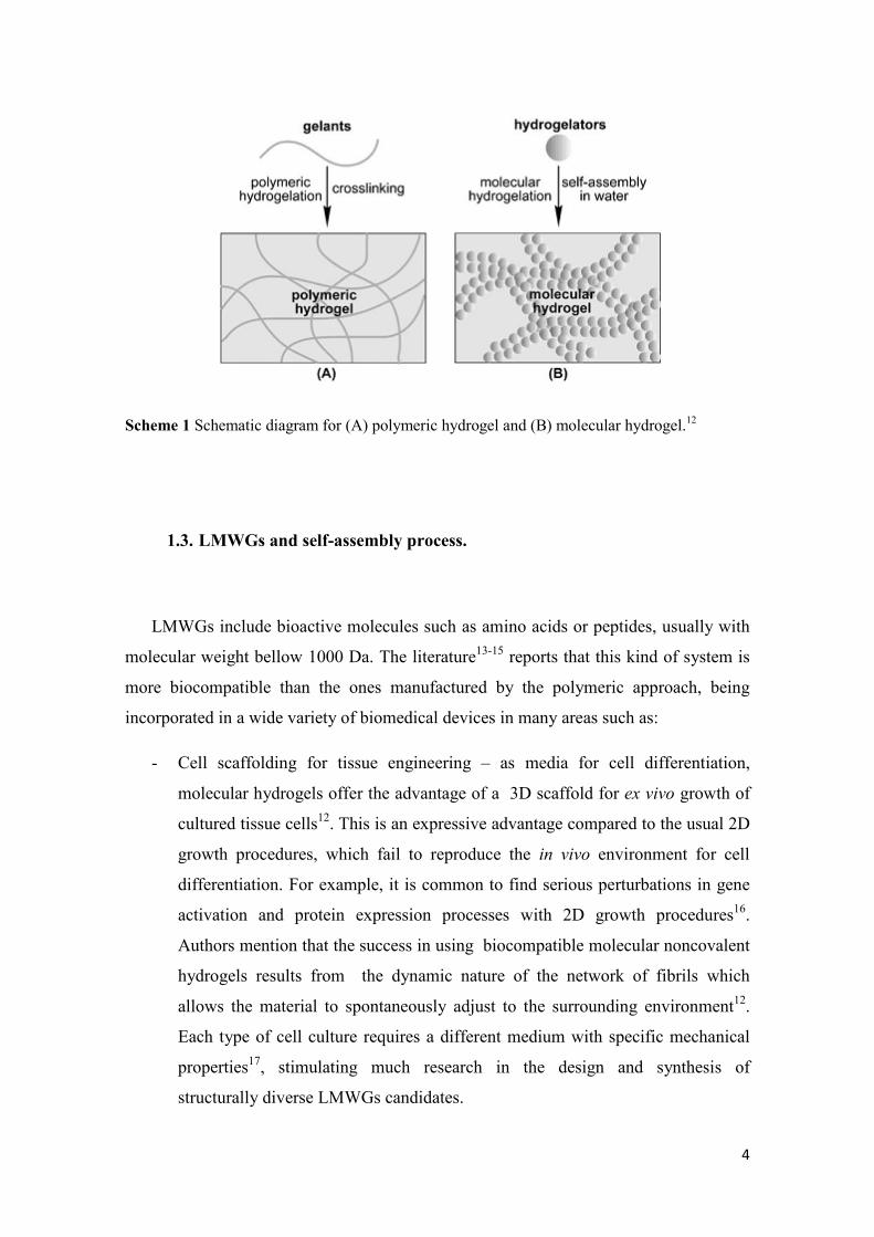
4
Scheme 1 Schematic diagram for (A) polymeric hydrogel and (B) molecular hydrogel.12
1.3. LMWGs and self-assembly process.
LMWGs include bioactive molecules such as amino acids or peptides, usually with
molecular weight bellow 1000 Da. The literature13-15 reports that this kind of system is
more biocompatible than the ones manufactured by the polymeric approach, being
incorporated in a wide variety of biomedical devices in many areas such as:
- Cell scaffolding for tissue engineering – as media for cell differentiation,
molecular hydrogels offer the advantage of a 3D scaffold for ex vivo growth of
cultured tissue cells12. This is an expressive advantage compared to the usual 2D
growth procedures, which fail to reproduce the in vivo environment for cell
differentiation. For example, it is common to find serious perturbations in gene
activation and protein expression processes with 2D growth procedures16.
Authors mention that the success in using biocompatible molecular noncovalent
hydrogels results from the dynamic nature of the network of fibrils which
allows the material to spontaneously adjust to the surrounding environment12.
Each type of cell culture requires a different medium with specific mechanical
properties17, stimulating much research in the design and synthesis of
structurally diverse LMWGs candidates.
5
- In the pharmaceutical technology field: the intrinsic network of hydrogels can
protect drugs from environmental factors, like the presence of enzymes or
different pH environments found in living organisms. Hydrogels can also control
drug release through gel structural changes trigged by sol-gel phase transition
processes18.
- In regenerative medicinal processes: this approach is based on the ability of this
kind of colloidal systems to assist cell adhesion, promote growth of neurons or
to direct bone mineralization19.
Molecular self-assembly can be described as the spontaneous formation of ordered
structures under thermodynamic and kinetic control, through noncovalent interactions
between molecules20,21. Hierarchical nanostructures or macroscale fragments arise from
the self-association process.
Self-assembly is crucial for life maintenance processes, like the organization of
phospholipids into biological membranes, DNA double helix assembly through
hydrogen bond interactions, disposal of microtubules or microfilaments along the
cellular life cycle phases. It also gives rise to the amyloid fibrils, which are proposed to
be the cause of neurological diseases like Alzheimer´s21.
Despite the high number of publications reporting the preparation of noncovalent
self-assembled hydrogels, there is a lack of understanding on how media composition
determines the properties of colloidal network structures and about the laws that govern
the dynamics of molecular gelation phenomena. In other words, there is a need for the
development of a relationship between the noncovalent forces that drive self-assembly
processes and hydrogelation22.
Amongst self-assembling LMWGs systems, peptide-based molecular
hydrogelators attracted the most extensive research efforts, owing probably to its
versatile synthetic pathways, excellent gelation ability, good biocompatibility and easy
tuning of bioactivity23-25.
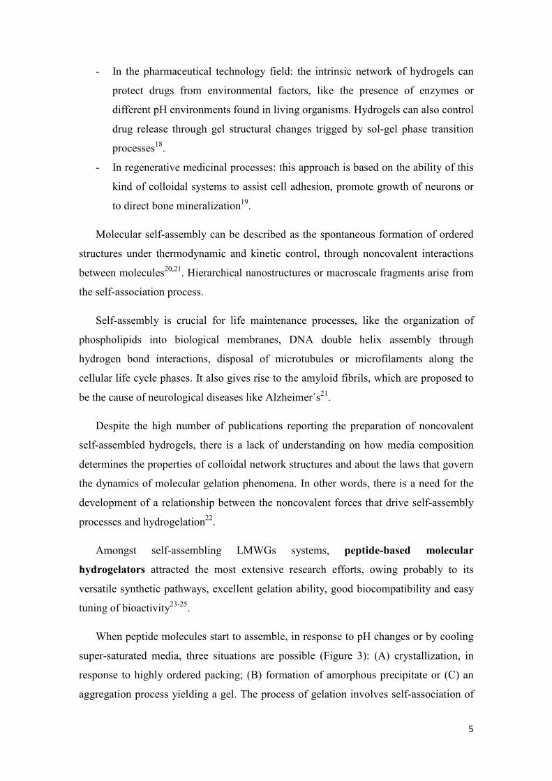
When peptide molecules start to assemble, in response to pH changes or by cooling
super-saturated media, three situations are possible (Figure 3): (A) crystallization, in
response to highly ordered packing; (B) formation of amorphous precipitate or (C) an
aggregation process yielding a gel. The process of gelation involves self-association of
6
molecules to form long, polymer-like fibrous aggregates, which get entangled during
the aggregation process leading to a matrix that traps solvent, mainly by surface tension.
This process prevents the flow of solvent under gravity and the material appears like a
solid26.
Figure 3 Schematic representation of different aggregation modes for peptide-based
molecular hydrogelators.26
1.4. Design of LMWGs.
Observing the protein motifs pattern, researchers realized that peptide self-assembly
is driven by intermolecular interactions, such as hydrogen bonding, ionic, electrostatic,
hydrophobic and Van der Waals interactions. Knowledge from molecular and structural
biology has inspired the design and synthesis of increasingly complex self-assembled
biomaterials for biomedicine and bionanotechnology. By engineering the amino acid
sequence, the secondary structure of peptides can be manipulated to optimize
interactions between adjacent peptides. Long-range organization of peptide monomers
produces nanofibrils which aggregate into 3D fibrous networks27.
7
There are many strategies to design self-assembling molecular materials based on
peptides and their derivatives. For peptides containing at least ten amino acids, the
supra-molecular structures observed are more frequently coiled-coils (α helical based
systems), β-sheets, β-hairpins, π-stacking systems and peptide amphiphiles 28a.
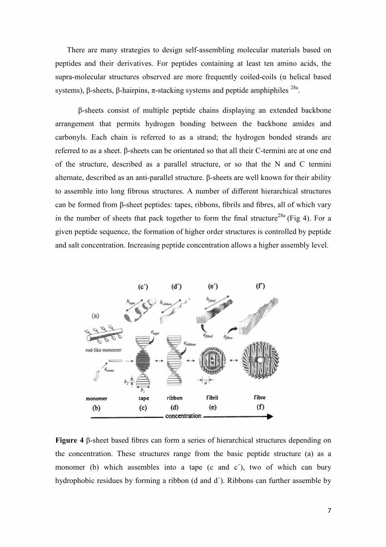
β-sheets consist of multiple peptide chains displaying an extended backbone
arrangement that permits hydrogen bonding between the backbone amides and
carbonyls. Each chain is referred to as a strand; the hydrogen bonded strands are
referred to as a sheet. β-sheets can be orientated so that all their C-termini are at one end
of the structure, described as a parallel structure, or so that the N and C termini
alternate, described as an anti-parallel structure. β-sheets are well known for their ability
to assemble into long fibrous structures. A number of different hierarchical structures
can be formed from β-sheet peptides: tapes, ribbons, fibrils and fibres, all of which vary
in the number of sheets that pack together to form the final structure28a (Fig 4). For a
given peptide sequence, the formation of higher order structures is controlled by peptide
and salt concentration. Increasing peptide concentration allows a higher assembly level.
Figure 4 β-sheet based fibres can form a series of hierarchical structures depending on
the concentration. These structures range from the basic peptide structure (a) as a
monomer (b) which assembles into a tape (c and c´), two of which can bury
hydrophobic residues by forming a ribbon (d and d´). Ribbons can further assemble by
8
lying face to face to form fibrils (e and e´) and additionally side by side to form fibres (f
and f´). Adapted from Ref. 27a 28a.
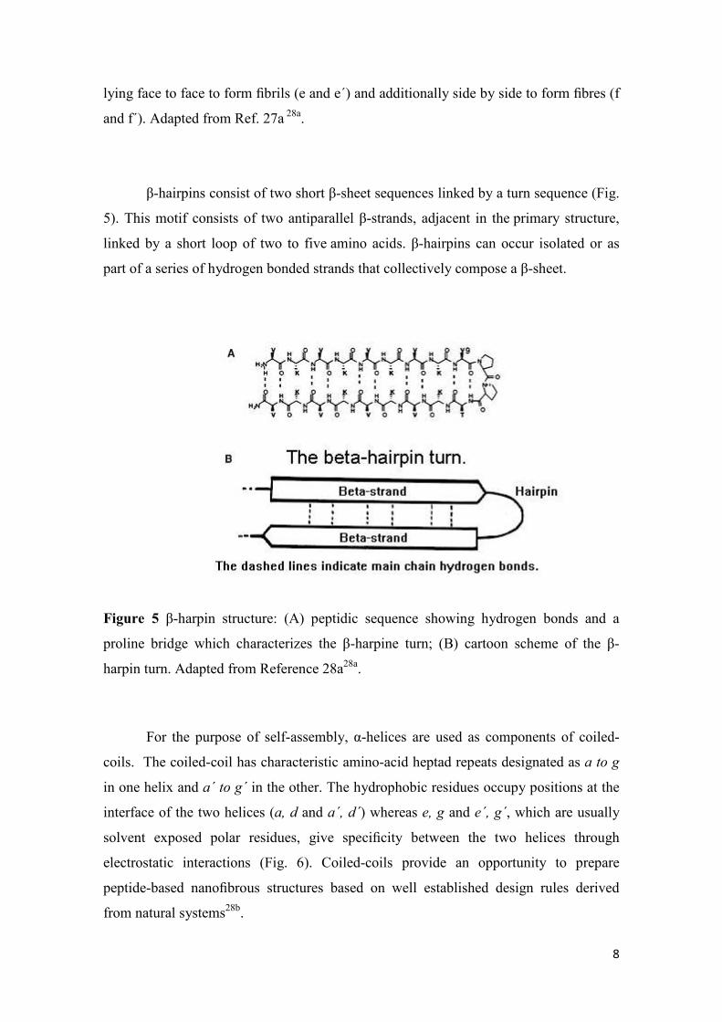
β-hairpins consist of two short β-sheet sequences linked by a turn sequence (Fig.
5). This motif consists of two antiparallel β-strands, adjacent in the primary structure,
linked by a short loop of two to five amino acids. β-hairpins can occur isolated or as
part of a series of hydrogen bonded strands that collectively compose a β-sheet.
Figure 5 β-harpin structure: (A) peptidic sequence showing hydrogen bonds and a
proline bridge which characterizes the β-harpine turn; (B) cartoon scheme of the β-
harpin turn. Adapted from Reference 28a28a.
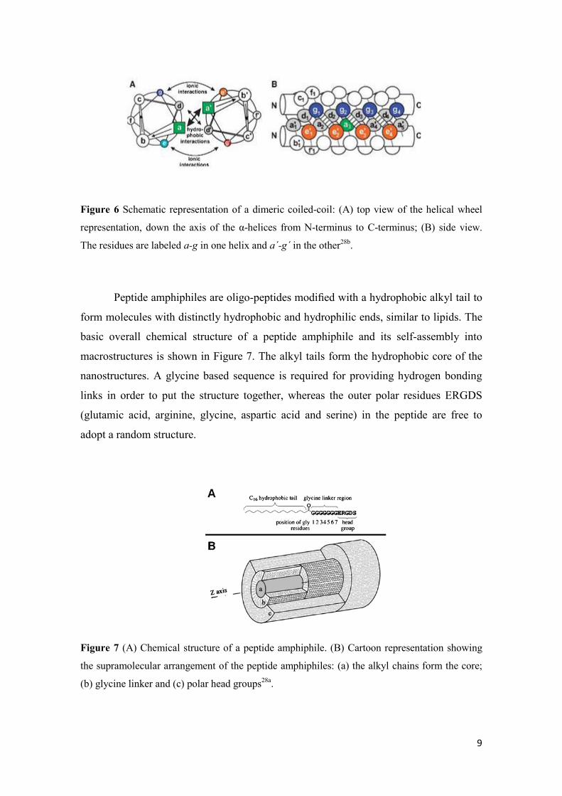
For the purpose of self-assembly, α-helices are used as components of coiled-
coils. The coiled-coil has characteristic amino-acid heptad repeats designated as a to g
in one helix and a´ to g´ in the other. The hydrophobic residues occupy positions at the
interface of the two helices (a, d and a´, d´) whereas e, g and e´, g´, which are usually
solvent exposed polar residues, give specificity between the two helices through
electrostatic interactions (Fig. 6). Coiled-coils provide an opportunity to prepare
peptide-based nanofibrous structures based on well established design rules derived
from natural systems28b.
9
Figure 6 Schematic representation of a dimeric coiled-coil: (A) top view of the helical wheel
representation, down the axis of the α-helices from N-terminus to C-terminus; (B) side view.
The residues are labeled a-g in one helix and a´-g´ in the other28b.
Peptide amphiphiles are oligo-peptides modified with a hydrophobic alkyl tail to
form molecules with distinctly hydrophobic and hydrophilic ends, similar to lipids. The
basic overall chemical structure of a peptide amphiphile and its self-assembly into
macrostructures is shown in Figure 7. The alkyl tails form the hydrophobic core of the
nanostructures. A glycine based sequence is required for providing hydrogen bonding
links in order to put the structure together, whereas the outer polar residues ERGDS
(glutamic acid, arginine, glycine, aspartic acid and serine) in the peptide are free to
adopt a random structure.
Figure 7 (A) Chemical structure of a peptide amphiphile. (B) Cartoon representation showing
the supramolecular arrangement of the peptide amphiphiles: (a) the alkyl chains form the core;
(b) glycine linker and (c) polar head groups28a.
10
Taking into account the motifs present in naturally occurring proteins, scientists
have moved towards designing new short self-assembling peptides amenable to
functionalization27. As peptides are so versatile building blocks, small peptides or even
single modified amino acids can self-assemble into networks, capable of entrapping
water and form hydrogels. This bottom-up approach lays its foundation on the high
level of self-assembly specificity of peptides, which is mainly dependent on the
recognition of intermolecular interactions between side chains in the peptide sequence.
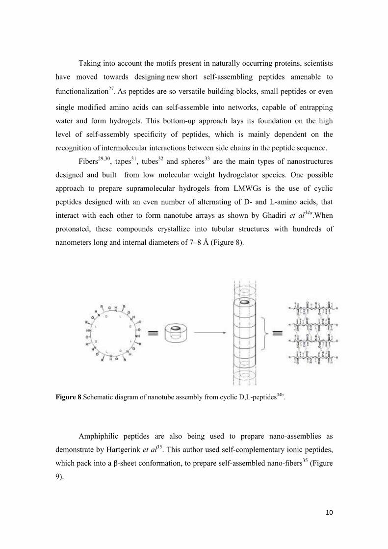
Fibers29,30, tapes31, tubes32 and spheres33 are the main types of nanostructures
designed and built from low molecular weight hydrogelator species. One possible
approach to prepare supramolecular hydrogels from LMWGs is the use of cyclic
peptides designed with an even number of alternating of D- and L-amino acids, that
interact with each other to form nanotube arrays as shown by Ghadiri et al34a.When
protonated, these compounds crystallize into tubular structures with hundreds of
nanometers long and internal diameters of 7–8 Å (Figure 8).
Figure 8 Schematic diagram of nanotube assembly from cyclic D,L-peptides34b.
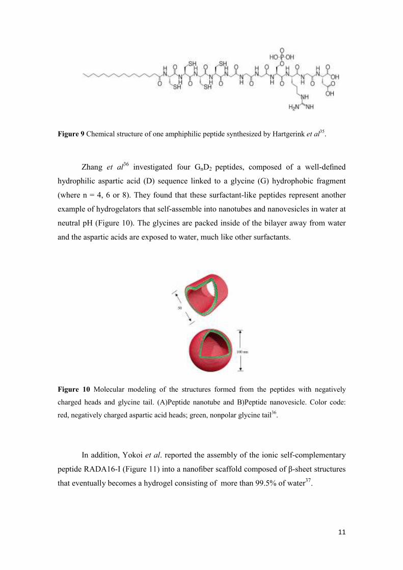
Amphiphilic peptides are also being used to prepare nano-assemblies as
demonstrate by Hartgerink et al35. This author used self-complementary ionic peptides,
which pack into a β-sheet conformation, to prepare self-assembled nano-fibers35 (Figure
9).
11
Figure 9 Chemical structure of one amphiphilic peptide synthesized by Hartgerink et al35.
Zhang et al36 investigated four GnD2 peptides, composed of a well-defined
hydrophilic aspartic acid (D) sequence linked to a glycine (G) hydrophobic fragment
(where n = 4, 6 or 8). They found that these surfactant-like peptides represent another
example of hydrogelators that self-assemble into nanotubes and nanovesicles in water at
neutral pH (Figure 10). The glycines are packed inside of the bilayer away from water
and the aspartic acids are exposed to water, much like other surfactants.
Figure 10 Molecular modeling of the structures formed from the peptides with negatively
charged heads and glycine tail. (A)Peptide nanotube and B)Peptide nanovesicle. Color code:
red, negatively charged aspartic acid heads; green, nonpolar glycine tail36.
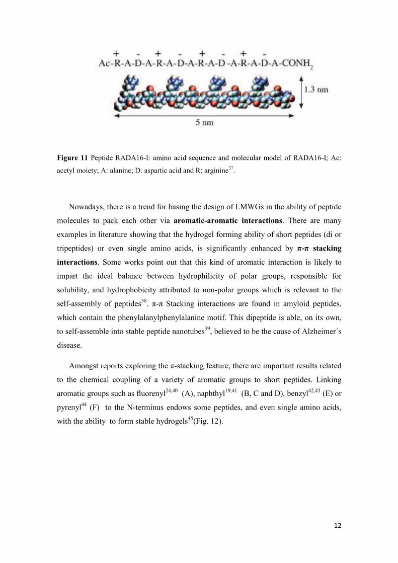
In addition, Yokoi et al. reported the assembly of the ionic self-complementary
peptide RADA16-I (Figure 11) into a nanofiber scaffold composed of β-sheet structures
that eventually becomes a hydrogel consisting of more than 99.5% of water37.
12
Figure 11 Peptide RADA16-I: amino acid sequence and molecular model of RADA16-I; Ac:
acetyl moiety; A: alanine; D: aspartic acid and R: arginine37.
Nowadays, there is a trend for basing the design of LMWGs in the ability of peptide
molecules to pack each other via aromatic-aromatic interactions. There are many
examples in literature showing that the hydrogel forming ability of short peptides (di or
tripeptides) or even single amino acids, is significantly enhanced by π-π stacking
interactions. Some works point out that this kind of aromatic interaction is likely to
impart the ideal balance between hydrophilicity of polar groups, responsible for
solubility, and hydrophobicity attributed to non-polar groups which is relevant to the
self-assembly of peptides38. π-π Stacking interactions are found in amyloid peptides,
which contain the phenylalanylphenylalanine motif. This dipeptide is able, on its own,
to self-assemble into stable peptide nanotubes39, believed to be the cause of Alzheimer´s
disease.
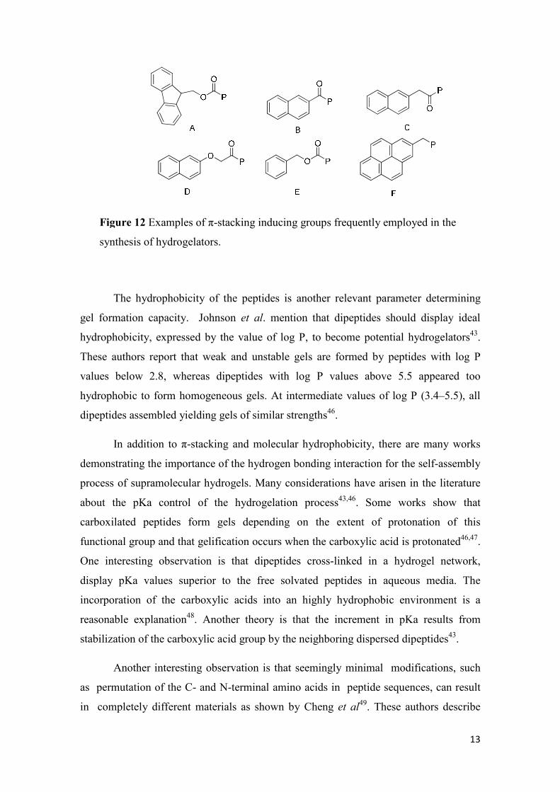
Amongst reports exploring the π-stacking feature, there are important results related
to the chemical coupling of a variety of aromatic groups to short peptides. Linking
aromatic groups such as fluorenyl24,40 (A), naphthyl19,41 (B, C and D), benzyl42,43 (E) or
pyrenyl44 (F) to the N-terminus endows some peptides, and even single amino acids,
with the ability to form stable hydrogels45(Fig. 12).
13
The hydrophobicity of the peptides is another relevant parameter determining
gel formation capacity. Johnson et al. mention that dipeptides should display ideal
hydrophobicity, expressed by the value of log P, to become potential hydrogelators43.
These authors report that weak and unstable gels are formed by peptides with log P
values below 2.8, whereas dipeptides with log P values above 5.5 appeared too
hydrophobic to form homogeneous gels. At intermediate values of log P (3.4–5.5), all
dipeptides assembled yielding gels of similar strengths46.
In addition to π-stacking and molecular hydrophobicity, there are many works
demonstrating the importance of the hydrogen bonding interaction for the self-assembly
process of supramolecular hydrogels. Many considerations have arisen in the literature
about the pKa control of the hydrogelation process43,46. Some works show that
carboxilated peptides form gels depending on the extent of protonation of this
functional group and that gelification occurs when the carboxylic acid is protonated46,47.
One interesting observation is that dipeptides cross-linked in a hydrogel network,
display pKa values superior to the free solvated peptides in aqueous media. The
incorporation of the carboxylic acids into an highly hydrophobic environment is a
reasonable explanation48. Another theory is that the increment in pKa results from
stabilization of the carboxylic acid group by the neighboring dispersed dipeptides43.
Another interesting observation is that seemingly minimal modifications, such
as permutation of the C- and N-terminal amino acids in peptide sequences, can result
in completely different materials as shown by Cheng et al49. These authors describe
Figure 12 Examples of π-stacking inducing groups frequently employed in the
synthesis of hydrogelators.
14
that the hydrogel formed by tripeptide Fmoc-Lys-Leu-Val-OH is composed by a
network of fibrils while the Fmoc-Val-Leu-Lys-OH hydrogel shows high level of
alignment in its fibrils. An additional example is provided by Adams et al50, who found
that the dipeptide Nap–Ala–Gly–OH is able to form hydrogels by just tuning pH, whilst
Nap–Gly–Ala–OH precipitates under the same conditions. Molecular modeling based
on X-ray diffraction studies, suggests that the different behavior observed for peptides
Nap–Ala–Gly–OH and Nap–Gly–Ala–OH could be ascribed to different conformations
and hydrogen bond preferences.
The degradation kinetics of hydrogels´s matrix has to be taken into account in
the design of hydrogelators. In this context, it is reasonable to assume that hydrogels
formed by natural proteinogenic peptide sequences are prone to degradation by
endogenous proteolitic enzymes. Introducing non proteinogenic amino acids into
peptide sequences could be useful to increase the proteolitic stability of hydrogels.
Peptides bearing non proteinogenic amino acids are being investigated in our research
group and in other research groups as potential hydrogelators. Non proteinous β-amino
acids, namely β-alanine residues, have recently been incorporated into dipeptide
hydrogelators. This modification yielded enzyme resistant hydrogels, which were used
as matrix for controlled-release of vitamins B12 and B2 at physiologic conditions51. A
supramolecular hydrogel based on (non natural) D-amino acids, resistant to proteinase
K catalysed-hydrolysis and exhibiting, thus, long-term bio-stability and in vivo
controlled drug release, was prepared by Xu et al.52
The introduction of non proteinogenic amino acids into peptides was also
explored by Gupta et al53
who evaluated the self-assembly process of a dipeptide made
of phenylalanine and α,β-dehydrophenylalanine. This non-coded achiral amino acid is
known to introduce constraints into molecular structures54,55,56. Non-proteinogenic
peptides offer the advantage of being less susceptible to enzyme degradation. Moreover,
non proteinogenic amino acids can add a positive contribution to the balance of the
thermodynamic forces that modulate peptide aggregation and water swelling processes.
More rigid structures should lead to a lower reduction in entropy when molecules self-
assemble.
Hydrogels with intrinsic medicinal properties can be created by incorporating
known therapeutic motifs, as organic modifiers, into hydrogelators. Anti-oxidants such
15
as catechol-derivatives have been introduced into chitosan/pluronic composite
hydrogels. These materials revealed improved tissue adhesion, characteristic of this type
of hydrogels, ideal for developing drug delivery systems, tissue engineering
applications or even as tissue adhesives to arrest bleeding57.
1.5. Methods for characterization of hydrogels
The usual methods for characterizing the molecular arrangement of nanofibrils in
hydrogels are inherently low-resolution9. UV-vis absorption, Fourier Transform
Infrared spectroscopy (FTIR), fluorescence and circular dichroism (CD) spectroscopy
can be used to evaluate the characteristics of the secondary structure and electronic
properties of these materials58.
FTIR spectroscopy is employed to confirm the presence of H-bonds and determine
the protonation state of carboxylic acids59-62. The C=O and N-H stretching vibration
bands from terminal carboxyl and amide groups directly reflect their ionization state and
potential involvement in hydrogen bonds62,63. Some bands of interest (like NH stretch)
can appear overlapping the OH stretch of water. Thus, FTIR analysis of hydrogels is
often performed using dehydrated samples. These outputs need to be analyzed with
caution, since structural modifications may occur due to water loss.
UV/Vis characterization of hydrogels is usually conducted using two different
approaches. One possibility is to incorporate spectroscopic fluorescent probes into
gelators64,65. This is an effective design strategy; the large, flat aromatic surfaces of
fluorophores are likely to promote aggregation and, at the same time, a powerful tool for
evaluating the aggregation hydrophobic pockets66. UV/Vis is also used to detect
changes of hydrophobicity in the surroundings of reporter groups. Both, intrinsic
reporter groups, making part of the gelator molecule, or added extrinsic probes, can be
used to identify π-π stacking or metal coordination trigged aggregation58.
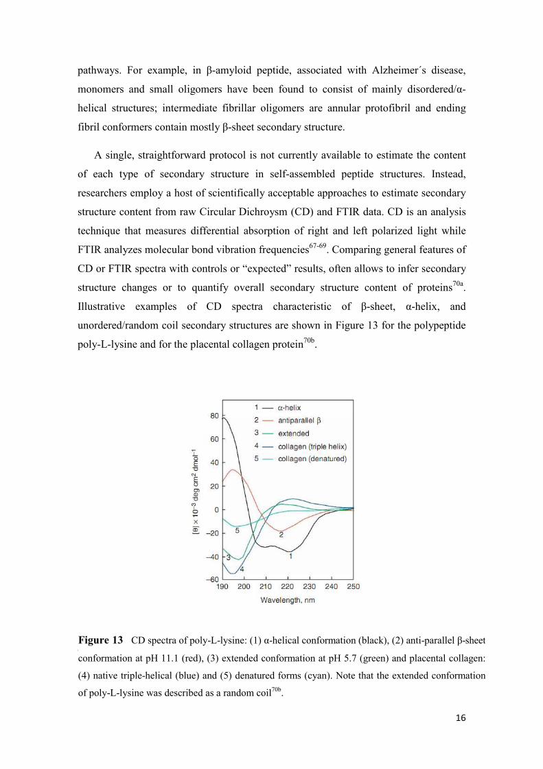
The secondary structure content of protein aggregates is an important parameter as
specific secondary structures are characteristic of different stages in aggregation
16
pathways. For example, in β-amyloid peptide, associated with Alzheimer´s disease,
monomers and small oligomers have been found to consist of mainly disordered/α-
helical structures; intermediate fibrillar oligomers are annular protofibril and ending
fibril conformers contain mostly β-sheet secondary structure.
A single, straightforward protocol is not currently available to estimate the content
of each type of secondary structure in self-assembled peptide structures. Instead,
researchers employ a host of scientifically acceptable approaches to estimate secondary
structure content from raw Circular Dichroysm (CD) and FTIR data. CD is an analysis
technique that measures differential absorption of right and left polarized light while
FTIR analyzes molecular bond vibration frequencies67-69. Comparing general features of
CD or FTIR spectra with controls or “expected” results, often allows to infer secondary
structure changes or to quantify overall secondary structure content of proteins70a.
Illustrative examples of CD spectra characteristic of β-sheet, α-helix, and
unordered/random coil secondary structures are shown in Figure 13 for the polypeptide
poly-L-lysine and for the placental collagen protein70b.
In a typical protein CD spectrum, there is a weak but broad n-π* transition
centered around 210 nm and an intense π-π* transition about 190 nm. Studies of far UV
Figure 13 CD spectra of poly-L-lysine: (1) α-helical conformation (black), (2) anti-parallel β-sheet
conformation at pH 11.1 (red), (3) extended conformation at pH 5.7 (green) and placental collagen:
(4) native triple-helical (blue) and (5) denatured forms (cyan). Note that the extended conformation
of poly-L-lysine was described as a random coil70b.
17
In a typical CD spectrum of a protein, there is a weak, but broad, n-π* transition
centered around 210 nm and an intense π-π* transition about 190 nm. Studies of far UV
CD can be used to assess quantitatively the overall secondary structure content of the
protein, since it has been known for many years that the different forms of regular
secondary structure found in peptides and proteins exhibit distinct spectra70c.
The near UV CD of proteins arises from the environments of each aromatic amino
acid side chain as well as possible contributions from disulphide bonds or non-protein
cofactors which might absorb in this spectral region. Small model compounds of the
aromatic amino acids exhibit CD spectra because the chromophore is linked to the
nearby chiral α-carbon atom. In the case of proteins in their native states, the side chains
of these amino acids will be placed in a variety of asymmetric environments
characteristic of the tertiary structure of the folded protein. A number of factors can
influence the CD spectra of aromatic amino acids. Among these are: the rigidity of the
protein, with the more highly mobile side chains having lower intensities; the nature of
the environment in terms of hydrogen bonding, polar groups and polarizability. In
addition the CD spectrum can be altered by interactions between aromatic amino acids
which are especially significant if the distance between them is less than 1 nm. In the
“exciton coupling” model, two excited states of chromophores, in close proximity,
result from exciton mixing of the two strong transitions; the states correspond to
symmetric and antisymmetric combinations of the excited state wave functions. The
two resulting CD bands will overlap with some cancellation (the extent of which
depends on the size of the interaction), giving rise to a sigmoidal CD curve. A final
factor is the number of aromatic amino acids in a protein. Proteins with large numbers
of such amino acids can have smaller CD bands than might be expected because of
cancelling effects of positive and negative contributions70c.
TEM, cryo-TEM and SEM are electron microscopy techniques useful to elucidate
fibril dimension and morphology, parameters relevant to infer length-to-mass
information about fibril building blocks22. Diffraction methods, including small-and
wide-angle X-ray, neutron and electron diffraction are appropriate to reveal the
molecular packing distances in the nanostructures and its dimensions in situ9.
18
However, to establish a better relationship between monomer structure, assembled
nanostructures and emergent hydrogel properties, it´s imperative to apply high-
resolution structural characterization methodologies9.
Crystallographic techniques are suitable for characterizing the atomic structure of
molecules. However, in order to be analyzed by these methods, the peptide
hydrogelators have to be crystalline materials, which often is not the case, as observed
for the amyloid peptides. That’s why sometimes is hard to implement this method for
the characterization of peptide self-assembled materials22,71. Moreover, it is necessary to
take into consideration that the scattering pattern obtained from single crystals differs
from that obtained from the nanofibers that compose hydrogels. Despite these
observations, it is accepted that single crystals provide good approximations of the
hydrogel state and that crystallographic methods are a powerful tool to allow further
insight into the architecture of self-assembled hydrogels at the molecular level72,73.
Solution phase NMR is ineffective for investigating self-assembled materials as
hydrogelator assembly into higher order structures broadens NMR signals due to
anisotropy effects74,75. On the other hand, the successful application of solid state (SS-
NMR) to the analysis of amyloid fibrils76, gives rise to the possibility of using this
methodology to analyze hydrogels on its native gel state. Isotopic labeling
bidimensional SS-NMR methods have been shown effective for mapping β-strand
motifs in several amyloid-forming proteins77-79. This opens the possibility of
characterizing cross-β fibril structures, which have many similarities to the nanofibers
observed in hydrogels´s network.
The information acquired through both low and high resolution techniques, can give
more robust insight into the parameters that govern the self-assembling process. These
techniques can provide constraints crucial for the development of computational models
that can describe hydrogels systems and help to design new hydrogelators displaying
desirable rheological properties or targeted behavior features. This kind of approach has
been implemented to develop theoretical models to the amyloid systems, and seems
satisfactory9.
This work reports the synthesis and characterization of new modified peptides that
contain phenylalanine and a dehydroamino acid and investigates their potential as
hydrogelator agents. The temperature and pH dependence of the gelification process
19
were also evaluated. The organic modifiers were chosen aiming to increase the aromatic
character of the peptides, which could lead to more efficient hydrogelators suitable as
biomaterials.
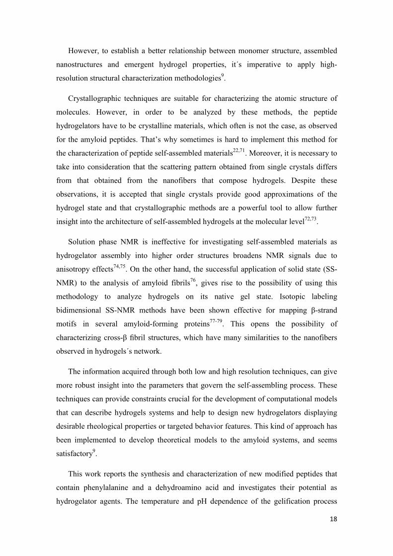
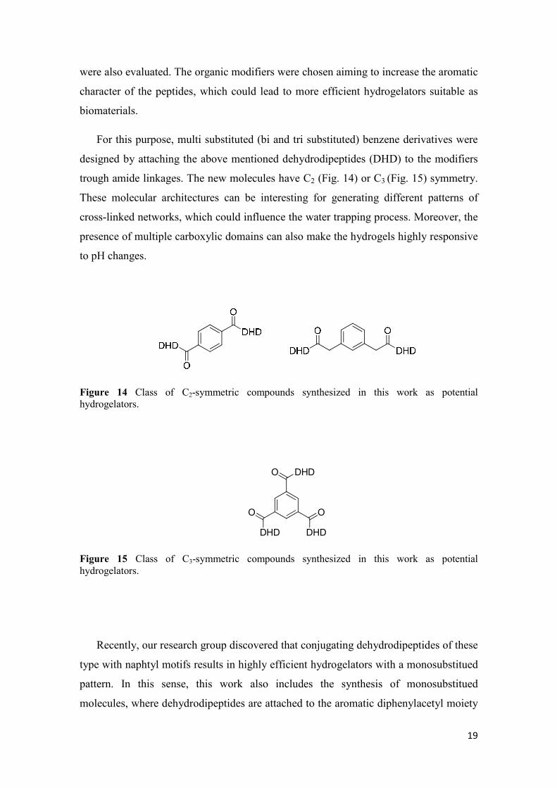
For this purpose, multi substituted (bi and tri substituted) benzene derivatives were
designed by attaching the above mentioned dehydrodipeptides (DHD) to the modifiers
trough amide linkages. The new molecules have C2 (Fig. 14) or C3 (Fig. 15) symmetry.
These molecular architectures can be interesting for generating different patterns of
cross-linked networks, which could influence the water trapping process. Moreover, the
presence of multiple carboxylic domains can also make the hydrogels highly responsive
to pH changes.
Figure 14 Class of C2-symmetric compounds synthesized in this work as potential hydrogelators.
O
O O
DHD
DHD
DHD
Figure 15 Class of C3-symmetric compounds synthesized in this work as potential hydrogelators.
Recently, our research group discovered that conjugating dehydrodipeptides of these
type with naphtyl motifs results in highly efficient hydrogelators with a monosubstitued
pattern. In this sense, this work also includes the synthesis of monosubstitued
molecules, where dehydrodipeptides are attached to the aromatic diphenylacetyl moiety
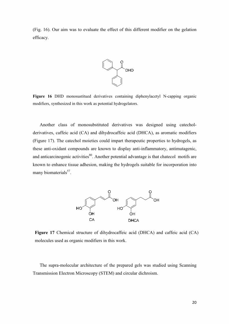
20
(Fig. 16). Our aim was to evaluate the effect of this different modifier on the gelation
efficacy.
Figure 16 DHD monosustitued derivatives containing diphenylacetyl N-capping organic
modifiers, synthesized in this work as potential hydrogelators.
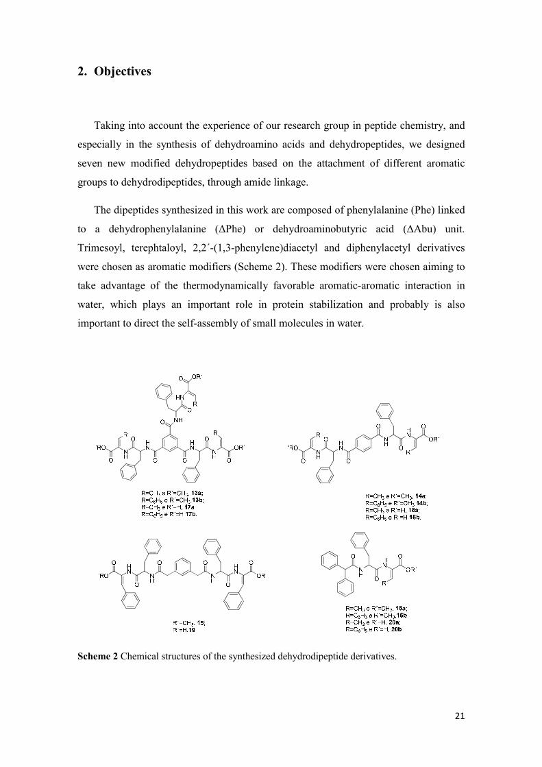
Another class of monosubstituted derivatives was designed using catechol-
derivatives, caffeic acid (CA) and dihydrocaffeic acid (DHCA), as aromatic modifiers
(Figure 17). The catechol moieties could impart therapeutic properties to hydrogels, as
these anti-oxidant compounds are known to display anti-inflammatory, antimutagenic,
and anticarcinogenic activities80. Another potential advantage is that chatecol motifs are
known to enhance tissue adhesion, making the hydrogels suitable for incorporation into
many biomaterials57.
The supra-molecular architecture of the prepared gels was studied using Scanning
Transmission Electron Microscopy (STEM) and circular dichroism.
Figure 17 Chemical structure of dihydrocaffeic acid (DHCA) and caffeic acid (CA)
molecules used as organic modifiers in this work.
21
2. Objectives
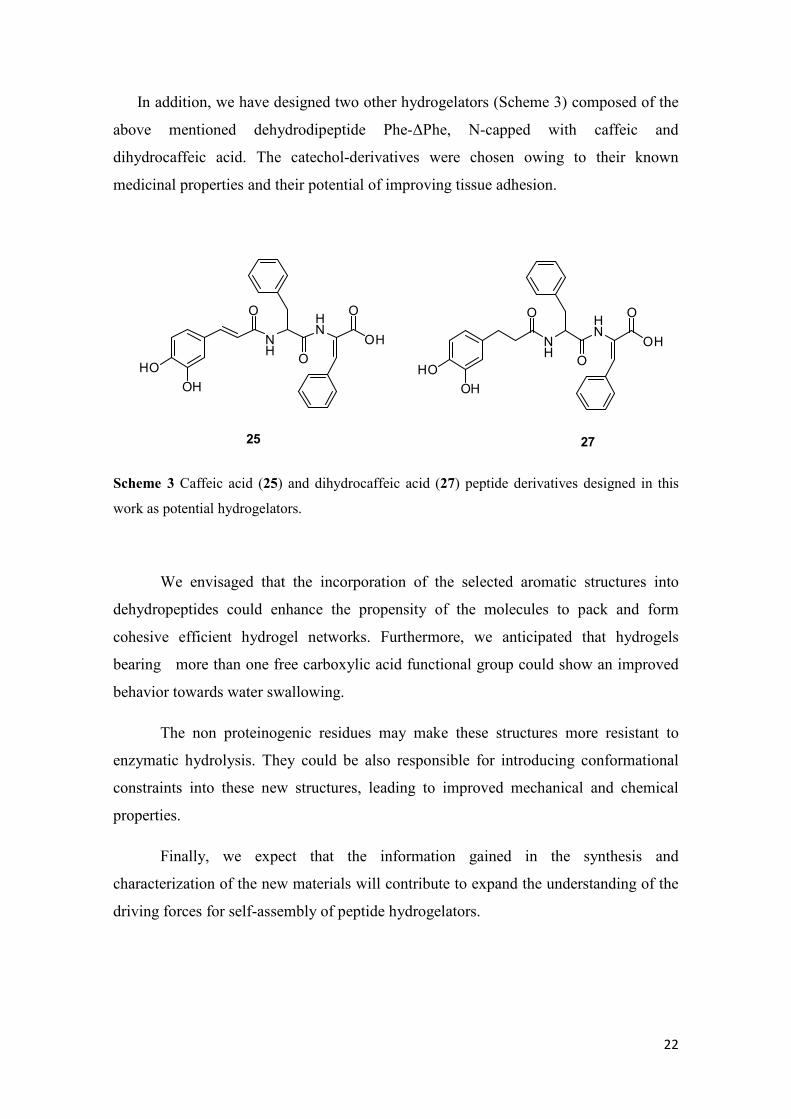
Taking into account the experience of our research group in peptide chemistry, and
especially in the synthesis of dehydroamino acids and dehydropeptides, we designed
seven new modified dehydropeptides based on the attachment of different aromatic
groups to dehydrodipeptides, through amide linkage.
The dipeptides synthesized in this work are composed of phenylalanine (Phe) linked
to a dehydrophenylalanine (∆Phe) or dehydroaminobutyric acid (∆Abu) unit.
Trimesoyl, terephtaloyl, 2,2´-(1,3-phenylene)diacetyl and diphenylacetyl derivatives
were chosen as aromatic modifiers (Scheme 2). These modifiers were chosen aiming to
take advantage of the thermodynamically favorable aromatic-aromatic interaction in
water, which plays an important role in protein stabilization and probably is also
important to direct the self-assembly of small molecules in water.
Scheme 2 Chemical structures of the synthesized dehydrodipeptide derivatives.
22
In addition, we have designed two other hydrogelators (Scheme 3) composed of the
above mentioned dehydrodipeptide Phe-∆Phe, N-capped with caffeic and
dihydrocaffeic acid. The catechol-derivatives were chosen owing to their known
medicinal properties and their potential of improving tissue adhesion.
HO
OH
O
NH
HN
O
O
OH
HO
OH
O
NH
HN
O
O
OH
25 27
Scheme 3 Caffeic acid (25) and dihydrocaffeic acid (27) peptide derivatives designed in this
work as potential hydrogelators.
We envisaged that the incorporation of the selected aromatic structures into
dehydropeptides could enhance the propensity of the molecules to pack and form
cohesive efficient hydrogel networks. Furthermore, we anticipated that hydrogels
bearing more than one free carboxylic acid functional group could show an improved
behavior towards water swallowing.
The non proteinogenic residues may make these structures more resistant to
enzymatic hydrolysis. They could be also responsible for introducing conformational
constraints into these new structures, leading to improved mechanical and chemical
properties.
Finally, we expect that the information gained in the synthesis and
characterization of the new materials will contribute to expand the understanding of the
driving forces for self-assembly of peptide hydrogelators.
23
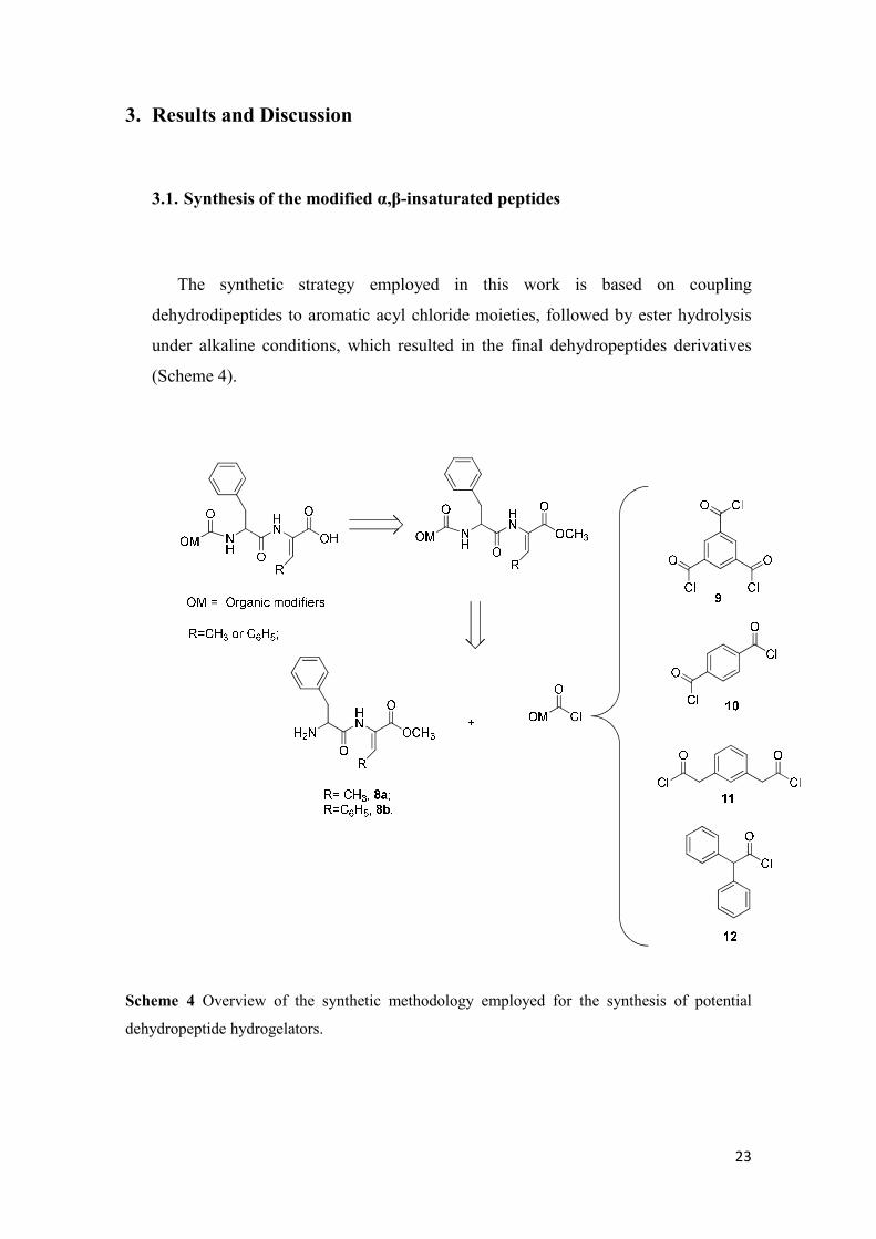
3. Results and Discussion
3.1. Synthesis of the modified α,β-insaturated peptides
The synthetic strategy employed in this work is based on coupling
dehydrodipeptides to aromatic acyl chloride moieties, followed by ester hydrolysis
under alkaline conditions, which resulted in the final dehydropeptides derivatives
(Scheme 4).
Scheme 4 Overview of the synthetic methodology employed for the synthesis of potential
dehydropeptide hydrogelators.
24
3.2. Synthesis of the dehydropeptides
The production of the α,β-dehydroamino acids was the key step in the synthetic
route. Amongst all the methods described in literature for the synthesis of
α,β-dehydroamino acids, the most widespread is the dehydration of β-hydroxyamino
acids, like serine or threonine, which yield the corresponding ∆Ala and ∆Abu
residues81-83. Other methodologies include the Hoffman degradation of α,β-
diaminopropionyl residues84, hydrolysis of unsaturated oxazolinones, reduction of
azidoacrylates85 or condensation of α-ketoacids with amines or nitriles86,87. However,
most of these are low-yielding, multistep and non stereospecific methods, requiring a lot
of effort to remove side products.
In this work, we have used methodologies developed in our research group for the
synthesis of the α,β-dehydroamino acid synthetic blocks88. These consisted of 4-
dimethylaminopyridine (DMAP) catalyzed reaction of β-hydroxyamino acids with tert-
butyl pyrocarbonate [Boc2O], followed by treatment with N,N,N’,N’-tetramethylguanidine
(TMG), which is known to lead to dehydroamino acids in high yields. The
retrosynthetic pathway for the synthesis of dehydropeptides 8a and 8b is presented in
Scheme 5.
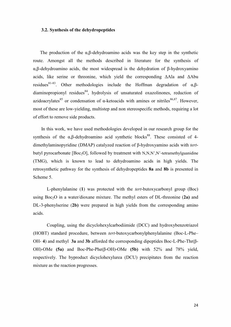
L-phenylalanine (1) was protected with the tert-butoxycarbonyl group (Boc)
using Boc2O in a water/dioxane mixture. The methyl esters of DL-threonine (2a) and
DL-3-phenylserine (2b) were prepared in high yields from the corresponding amino
acids.
Coupling, using the dicyclohexylcarbodiimide (DCC) and hydroxybenzotriazol
(HOBT) standard procedure, between tert-butoxycarbonylphenylalanine (Boc-L-Phe–
OH- 4) and methyl 3a and 3b afforded the corresponding dipeptides Boc-L-Phe-Thr(β-
OH)-OMe (5a) and Boc-Phe-Phe(β-OH)-OMe (5b) with 52% and 78% yield,
respectively. The byproduct dicyclohexylurea (DCU) precipitates from the reaction
mixture as the reaction progresses.
25
Scheme 5 Retrosynthetic analysis for the synthesis of the dehydrodipeptides Boc-L-Phe-Z-
∆Abu-OMe (8a) and Boc-L-Phe-Z-∆Phe-OMe (8b).
Carbodiimide activation of amino acid derivatives often results in partial
racemization of the amino acid. This happens because the intermediate O-acyl ureas are
highly reactive and can lead to oxazolone intermediates, which rearrange giving
undesired racemized products (Scheme 6).

26
Scheme 6 Activation of the carboxylic acid group with a carbodiimide reagent and possible side
reactions. I: rearrangement of the N-acyl urea derivative; II: racemization (P = protecting group,
R = lateral chain of the amino acid, R2 = carbon chain of the coupling amino acid; R3 = alkyl
chain of the carbodiimide compound).
To avoid this problem is useful to add to the reaction mixture one molar
equivalent of 1-hydroxybenzotriazole (HOBt). The active hydroxybenzotriazole esters,
formed as intermediates, couple to primary amines with little racemization. The
mechanism is shown in Scheme 7.
Scheme 7 Mechanism for the DCC/HOBt coupling reaction.
27
Dipeptides 5a and 5b were dehydrated by treatment with 1.1 molar equivalent of
Boc2O in the presence of a catalytic amount of DMAP. Without being isolated, the
resulting O-tert-butylcarbonyl peptides 6a and 6b were reacted with TMG affording
dedydrodipeptides 7a and 7b in good yields. DMAP catalyzes the acylation process
promoted by the di-tert-butyldicarbonate reactant to yield O-tert-butyl carbonates which
finally were dehydrated (in a one pot reaction) by the use of TMG. This reaction step
appears to be stereospecific towards the more thermodynamically stable Z-isomer.
The stereochemistry of the α,β-dehydroamino acids was elucidated by NOE
difference experiments, irradiating the α-NH protons and observing a NOE effect on the
β-methyl or β-phenyl protons.
The Boc group was removed by treatment with trifluoracetic acid (TFA) (which
protonates the nitrogen in the amide functional group, resulting in release of CO2 and
formation of t-butanol side-product) giving the desired products 8a and 8b as
trifluoracetate salts with 87% and 92% yield, respectively.
3.3. Peptide coupling to aromatic modifiers
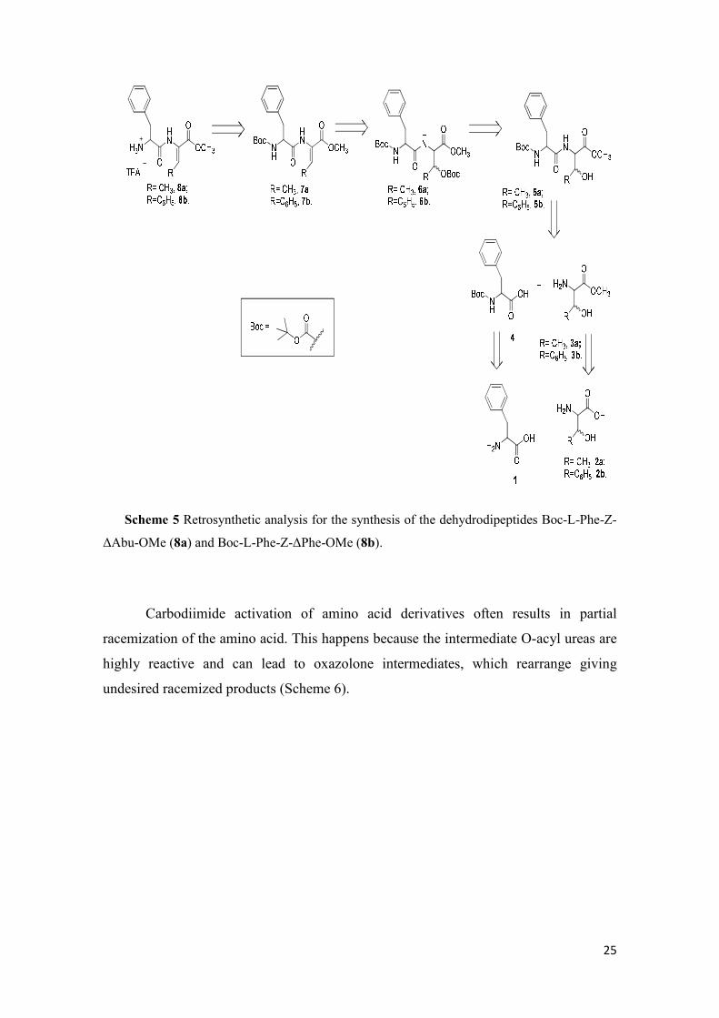
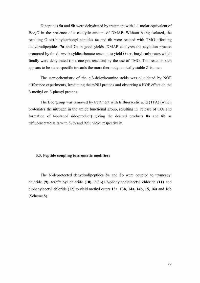
The N-deprotected dehydrodipeptides 8a and 8b were coupled to trymesoyl
chloride (9), tereftaloyl chloride (10), 2,2´-(1,3-phenylene)diacetyl chloride (11) and
diphenylacetyl chloride (12) to yield methyl esters 13a, 13b, 14a, 14b, 15, 16a and 16b
(Scheme 8).
28
Scheme 8 Structure of the compounds obtained from the coupling reaction of 8a and 8b with
organic modifiers. Isolated yields (%) are also indicated.
It was anticipated that the synthesis of multi-substituted hydrogelators based on
the organic modifiers trimesoyl (9) and terephtaloyl (10) could reveal more challenging
than the synthesis of simpler mono-substituted hydrogelators owing to steric crowding
and unfavorable entropy contribution to the process.
In order to optimize the reaction yield, four different solvents were tested in the
coupling reactions between peptides and the multi-substituted organic modifiers 9 and
10. The best choice for both dehydrodipeptides was dry THF which afforded the highest
yields (Table 1).
29
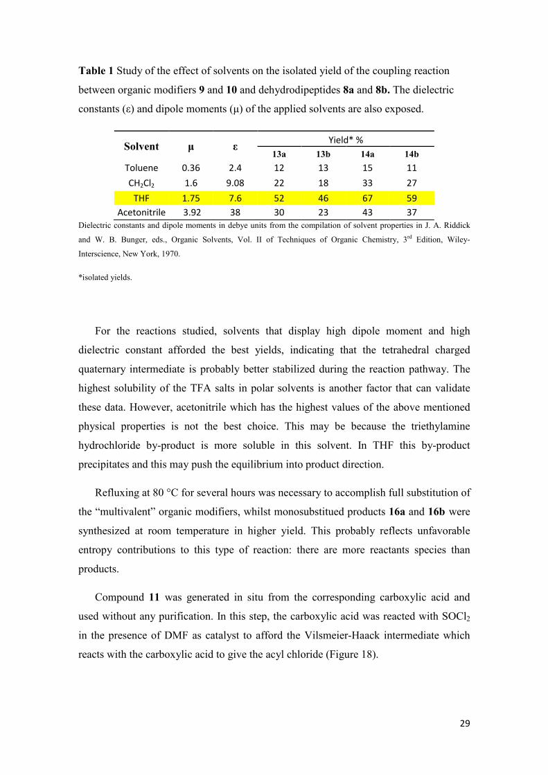
Table 1 Study of the effect of solvents on the isolated yield of the coupling reaction
between organic modifiers 9 and 10 and dehydrodipeptides 8a and 8b. The dielectric
constants (ε) and dipole moments (µ) of the applied solvents are also exposed.
Solvent µ ε Yield* %
13a 13b 14a 14b
Toluene 0.36 2.4 12 13 15 11
CH2Cl2 1.6 9.08 22 18 33 27
THF 1.75 7.6 52 46 67 59
Acetonitrile 3.92 38 30 23 43 37
Dielectric constants and dipole moments in debye units from the compilation of solvent properties in J. A. Riddick
and W. B. Bunger, eds., Organic Solvents, Vol. II of Techniques of Organic Chemistry, 3rd Edition, Wiley-
Interscience, New York, 1970.
*isolated yields.
For the reactions studied, solvents that display high dipole moment and high
dielectric constant afforded the best yields, indicating that the tetrahedral charged
quaternary intermediate is probably better stabilized during the reaction pathway. The
highest solubility of the TFA salts in polar solvents is another factor that can validate
these data. However, acetonitrile which has the highest values of the above mentioned
physical properties is not the best choice. This may be because the triethylamine
hydrochloride by-product is more soluble in this solvent. In THF this by-product
precipitates and this may push the equilibrium into product direction.
Refluxing at 80 °C for several hours was necessary to accomplish full substitution of
the “multivalent” organic modifiers, whilst monosubstitued products 16a and 16b were
synthesized at room temperature in higher yield. This probably reflects unfavorable
entropy contributions to this type of reaction: there are more reactants species than
products.
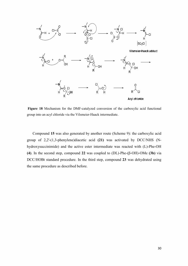
Compound 11 was generated in situ from the corresponding carboxylic acid and
used without any purification. In this step, the carboxylic acid was reacted with SOCl2
in the presence of DMF as catalyst to afford the Vilsmeier-Haack intermediate which
reacts with the carboxylic acid to give the acyl chloride (Figure 18).
30
Figure 18 Mechanism for the DMF-catalyzed conversion of the carboxylic acid functional
group into an acyl chloride via the Vilsmeier-Haack intermediate.
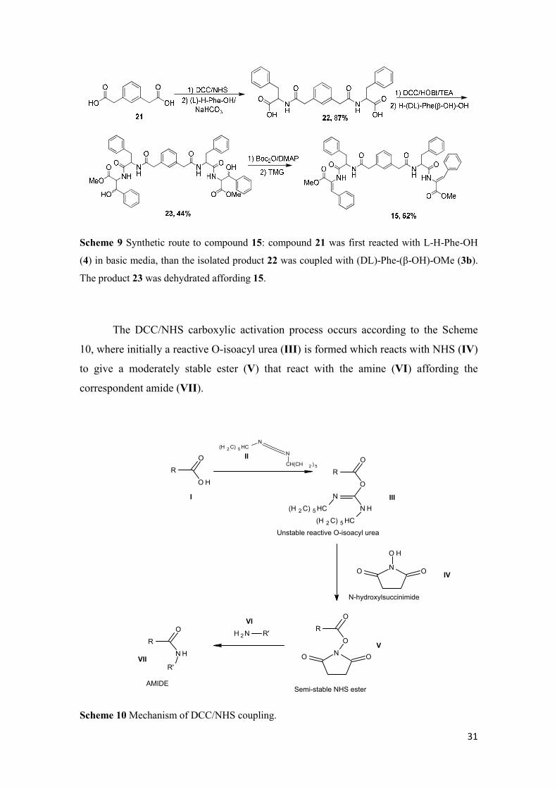
Compound 15 was also generated by another route (Scheme 9): the carboxylic acid
group of 2,2'-(1,3-phenylene)diacetic acid (21) was activated by DCC/NHS (N-
hydroxysuccinimide) and the active ester intermediate was reacted with (L)-Phe-OH
(4). In the second step, compound 22 was coupled to (DL)-Phe-(β-OH)-OMe (3b) via
DCC/HOBt standard procedure. In the third step, compound 23 was dehydrated using
the same procedure as described before.
31
Scheme 9 Synthetic route to compound 15: compound 21 was first reacted with L-H-Phe-OH
(4) in basic media, than the isolated product 22 was coupled with (DL)-Phe-(β-OH)-OMe (3b).
The product 23 was dehydrated affording 15.
The DCC/NHS carboxylic activation process occurs according to the Scheme
10, where initially a reactive O-isoacyl urea (III) is formed which reacts with NHS (IV)
to give a moderately stable ester (V) that react with the amine (VI) affording the
correspondent amide (VII).
R
O H
O
N
N
(H 2C) 5HC
CH(CH 2 ) 5
R
O
O
NH
N
(H 2C) 5HC
(H 2C) 5HC
Unstable reactive O-isoacyl urea
N
O H
OO
N-hydroxylsuccinimide
R
O
O
NO O
Semi-stable NHS ester
NH 2 R'R
NH
O
R'
AMIDE
I
II
III
IV
V
VI
VII
Scheme 10 Mechanism of DCC/NHS coupling.
32
The 1H-NMR spectrum showed clear evidence of amide linkage formation without
any evidence of isomerization of the target compounds. In Figure 19 is presented the
spectra of compound 13b. Characteristic signals and features, common to all
dehydrodipeptide conjugates, are briefly discussed:
- The β protons (yellow) of phenylalanine appears as double doublets (dd) in the
range of 3.0-3.3 ppm. These protons are classified as diasterotopic protons due
to the presence of the chiral center at the α-carbon. There is a strong coupling
between these geminal hydrogens and they couple with the α-proton with
significantly different coupling constants. The α-proton and the β-protons have
to be evaluated as an ABX system and the spectrum needs to be seen as a second
order one. A and B represent the CH2 β-protons which have similar chemical
shifts and X corresponds to the α-proton that displays a significantly different
chemical shift. The one that is less shielded couples with a higher coupling
constant with the α-proton and its dd have a more complicated pattern because
the relation ∆νβH-αH/JβH-αH is lower than the one for the other germinal proton;
- The ester protons (green) appear around 3.6-3.7 ppm as a singlet;
- The α-proton (orange) appears as multiplet in the range of 4.7-5.0 ppm and
results from the couplings with the diasterotopic protons of the β-CH2 and with
the α-NH
- The aromatic protons appear in the region of 7.0-8.4 ppm;
- The amide proton (blue), that results from the coupling, has its signal around
8.6-9.0 ppm and is a doublet, because it couples with the α-proton;
- The amide ∆Phe α-NH proton (red) or the ∆Abu α-NH one appears as a singlet
between 9.5 and 10.0 ppm.

33
Figure 19 1H-NMR (400MHz) spectrum of compound 13b in DMSO.
One peculiarity of dehydropeptide derivatives composed of phenylalanine and
dehydropenylalanine is that the signal of the β-CH of ∆Phe (pink) appears in the
aromatic region as a broad singlet.
The dehydropeptide derivatives containing the dehydroaminobutyric amino acid
display the same pattern in the 1H-NMR spectra as described above, with the difference
that the β-CH of ∆Abu gives a quartet around 6.5-6.7 ppm and the γ-CH3 protons
appear in the region between 1.5 and 1.7 ppm as a doublet. These protons can be
considered an A3X system (two magnetic and chemically different groups of protons)
originating a first order like spectrum with a coupling constant around 7.2 Hz in all
compounds.
The final step in the synthesis involves ester hydrolysis under alkaline conditions in
dioxane. The carboxylic acid derivatives were tested for hydrogel formation, as
potential hydrogelators. In Figure 20 is shown the 1H-NMR spectrum for hydrogelator
20a.
HN N
O O
NH
ON
O
OO
O O
NH
HN
OO
O
O
H
HH
H
HH´H
34
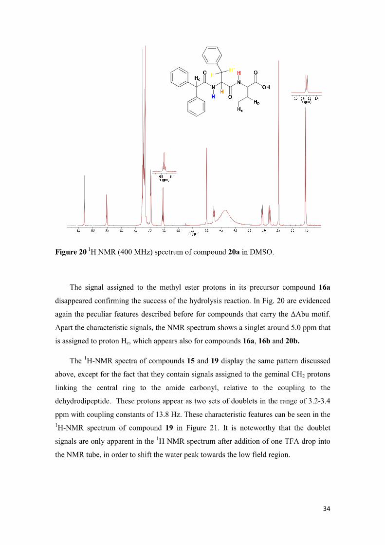
Figure 20 1H NMR (400 MHz) spectrum of compound 20a in DMSO.
The signal assigned to the methyl ester protons in its precursor compound 16a
disappeared confirming the success of the hydrolysis reaction. In Fig. 20 are evidenced
again the peculiar features described before for compounds that carry the ∆Abu motif.
Apart the characteristic signals, the NMR spectrum shows a singlet around 5.0 ppm that
is assigned to proton Hc, which appears also for compounds 16a, 16b and 20b.
The 1H-NMR spectra of compounds 15 and 19 display the same pattern discussed
above, except for the fact that they contain signals assigned to the geminal CH2 protons
linking the central ring to the amide carbonyl, relative to the coupling to the
dehydrodipeptide. These protons appear as two sets of doublets in the range of 3.2-3.4
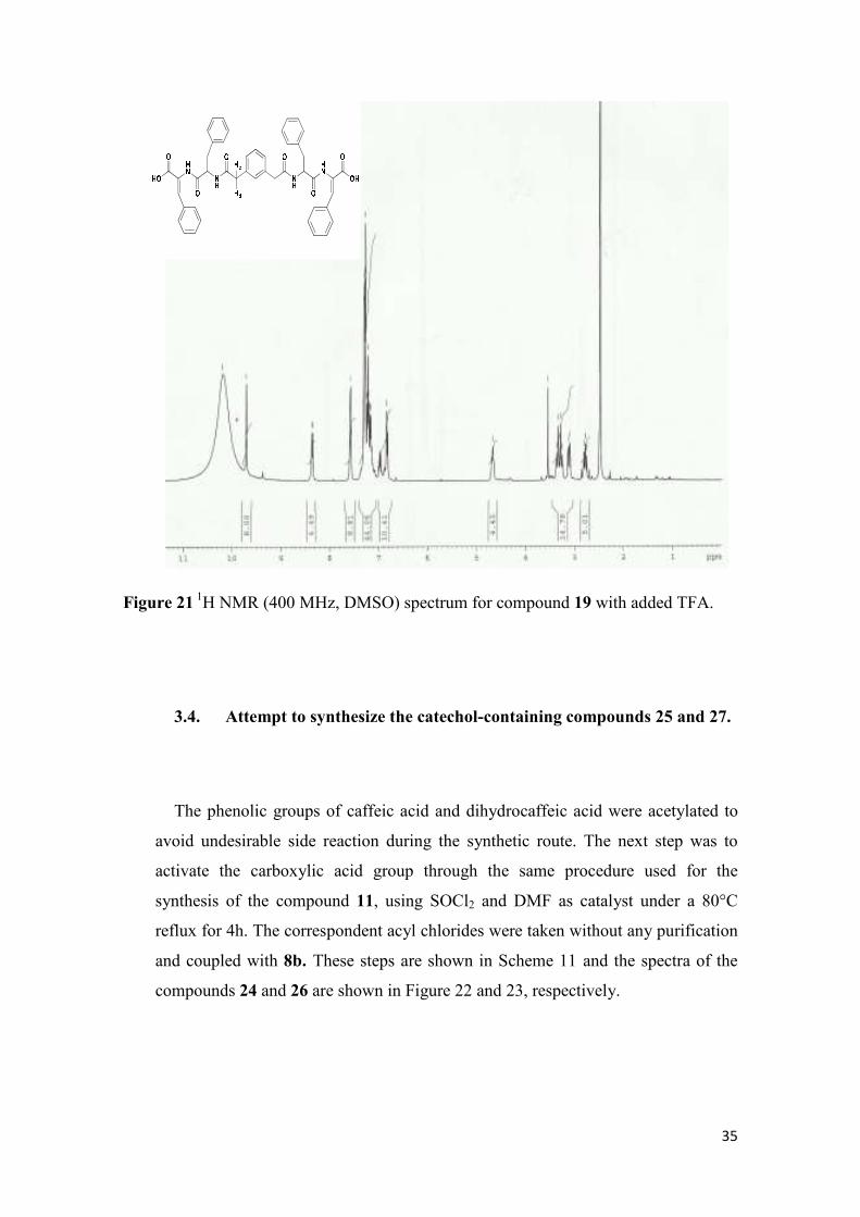
ppm with coupling constants of 13.8 Hz. These characteristic features can be seen in the 1H-NMR spectrum of compound 19 in Figure 21. It is noteworthy that the doublet
signals are only apparent in the 1H NMR spectrum after addition of one TFA drop into
the NMR tube, in order to shift the water peak towards the low field region.
35
Figure 21 1H NMR (400 MHz, DMSO) spectrum for compound 19 with added TFA.
3.4. Attempt to synthesize the catechol-containing compounds 25 and 27.
The phenolic groups of caffeic acid and dihydrocaffeic acid were acetylated to
avoid undesirable side reaction during the synthetic route. The next step was to
activate the carboxylic acid group through the same procedure used for the
synthesis of the compound 11, using SOCl2 and DMF as catalyst under a 80°C
reflux for 4h. The correspondent acyl chlorides were taken without any purification
and coupled with 8b. These steps are shown in Scheme 11 and the spectra of the
compounds 24 and 26 are shown in Figure 22 and 23, respectively.
36
Scheme 11 Synthetic route for the coupling of dehydropeptide 8b with caffeic acid (CA)
and dihydocaffeic acid (DHCA) leading to the compounds 24 and 26.
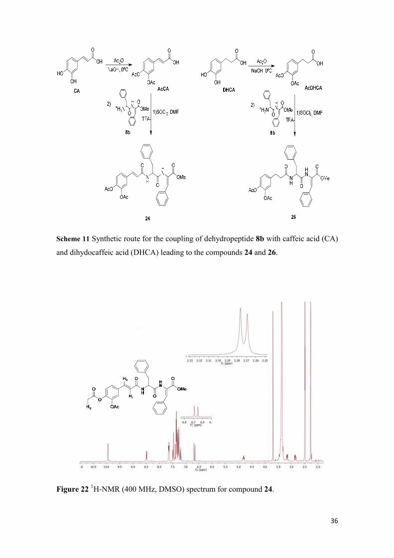
Figure 22 1H-NMR (400 MHz, DMSO) spectrum for compound 24.
37
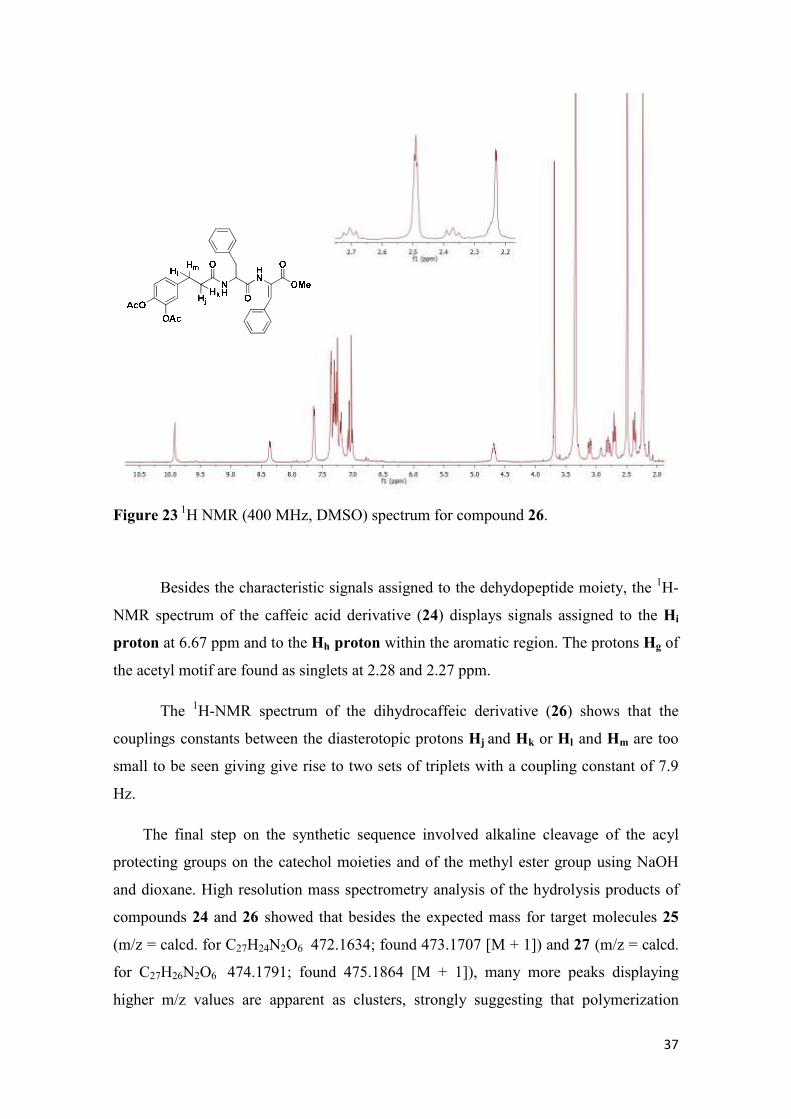
Figure 23 1H NMR (400 MHz, DMSO) spectrum for compound 26.
Besides the characteristic signals assigned to the dehydopeptide moiety, the 1H-
NMR spectrum of the caffeic acid derivative (24) displays signals assigned to the Hi
proton at 6.67 ppm and to the Hh proton within the aromatic region. The protons Hg of
the acetyl motif are found as singlets at 2.28 and 2.27 ppm.
The 1H-NMR spectrum of the dihydrocaffeic derivative (26) shows that the
couplings constants between the diasterotopic protons Hj and Hk or Hl and Hm are too
small to be seen giving give rise to two sets of triplets with a coupling constant of 7.9
Hz.
The final step on the synthetic sequence involved alkaline cleavage of the acyl
protecting groups on the catechol moieties and of the methyl ester group using NaOH
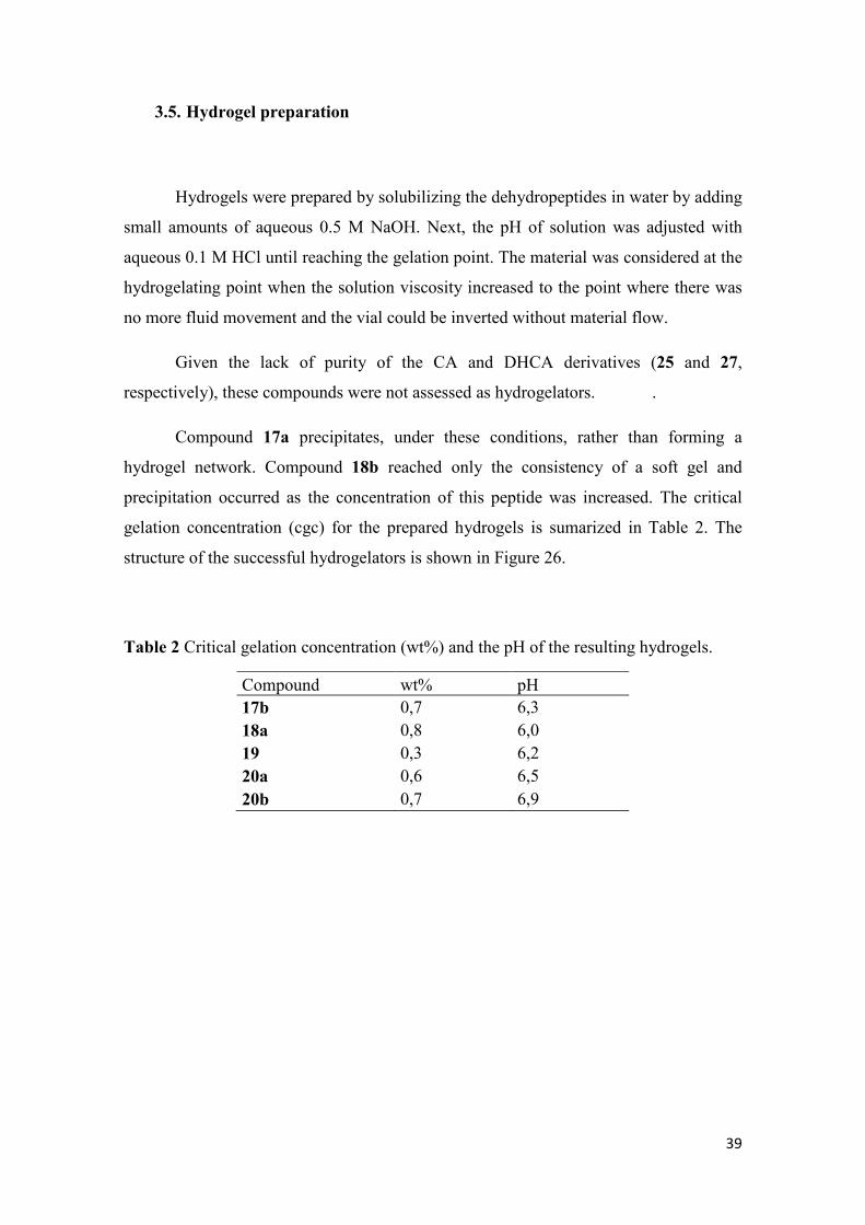
and dioxane. High resolution mass spectrometry analysis of the hydrolysis products of
compounds 24 and 26 showed that besides the expected mass for target molecules 25
(m/z = calcd. for C27H24N2O6 472.1634; found 473.1707 [M + 1]) and 27 (m/z = calcd.
for C27H26N2O6 474.1791; found 475.1864 [M + 1]), many more peaks displaying
higher m/z values are apparent as clusters, strongly suggesting that polymerization
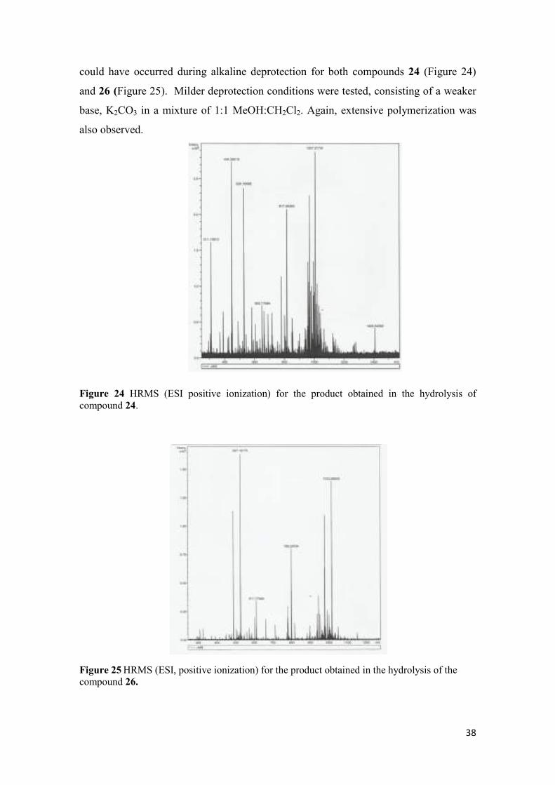
38
could have occurred during alkaline deprotection for both compounds 24 (Figure 24)
and 26 (Figure 25). Milder deprotection conditions were tested, consisting of a weaker
base, K2CO3 in a mixture of 1:1 MeOH:CH2Cl2. Again, extensive polymerization was
also observed.
Figure 24 HRMS (ESI positive ionization) for the product obtained in the hydrolysis of compound 24.
Figure 25 HRMS (ESI, positive ionization) for the product obtained in the hydrolysis of the compound 26.
39
3.5. Hydrogel preparation
Hydrogels were prepared by solubilizing the dehydropeptides in water by adding
small amounts of aqueous 0.5 M NaOH. Next, the pH of solution was adjusted with
aqueous 0.1 M HCl until reaching the gelation point. The material was considered at the
hydrogelating point when the solution viscosity increased to the point where there was
no more fluid movement and the vial could be inverted without material flow.
Given the lack of purity of the CA and DHCA derivatives (25 and 27,
respectively), these compounds were not assessed as hydrogelators. .
Compound 17a precipitates, under these conditions, rather than forming a
hydrogel network. Compound 18b reached only the consistency of a soft gel and
precipitation occurred as the concentration of this peptide was increased. The critical
gelation concentration (cgc) for the prepared hydrogels is sumarized in Table 2. The
structure of the successful hydrogelators is shown in Figure 26.
Table 2 Critical gelation concentration (wt%) and the pH of the resulting hydrogels.
Compound wt% pH 17b 0,7 6,3 18a 0,8 6,0 19 0,3 6,2 20a 0,6 6,5 20b 0,7 6,9
40
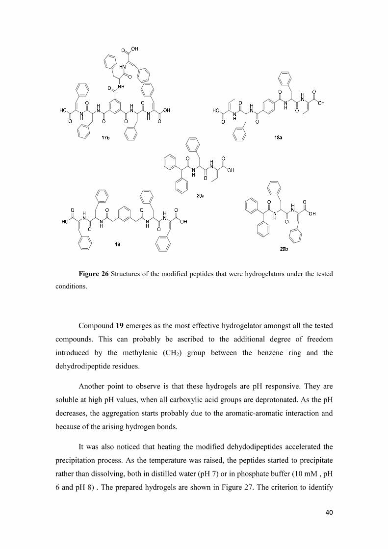
Figure 26 Structures of the modified peptides that were hydrogelators under the tested
conditions.
Compound 19 emerges as the most effective hydrogelator amongst all the tested
compounds. This can probably be ascribed to the additional degree of freedom
introduced by the methylenic (CH2) group between the benzene ring and the
dehydrodipeptide residues.
Another point to observe is that these hydrogels are pH responsive. They are
soluble at high pH values, when all carboxylic acid groups are deprotonated. As the pH
decreases, the aggregation starts probably due to the aromatic-aromatic interaction and
because of the arising hydrogen bonds.
It was also noticed that heating the modified dehydodipeptides accelerated the
precipitation process. As the temperature was raised, the peptides started to precipitate
rather than dissolving, both in distilled water (pH 7) or in phosphate buffer (10 mM , pH
6 and pH 8) . The prepared hydrogels are shown in Figure 27. The criterion to identify
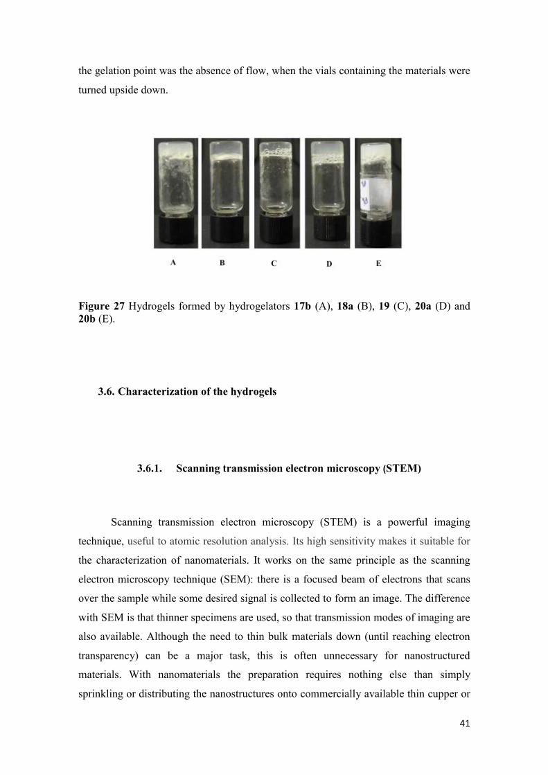
41
the gelation point was the absence of flow, when the vials containing the materials were
turned upside down.
Figure 27 Hydrogels formed by hydrogelators 17b (A), 18a (B), 19 (C), 20a (D) and 20b (E).
3.6. Characterization of the hydrogels
3.6.1. Scanning transmission electron microscopy (STEM)
Scanning transmission electron microscopy (STEM) is a powerful imaging
technique, useful to atomic resolution analysis. Its high sensitivity makes it suitable for
the characterization of nanomaterials. It works on the same principle as the scanning
electron microscopy technique (SEM): there is a focused beam of electrons that scans
over the sample while some desired signal is collected to form an image. The difference
with SEM is that thinner specimens are used, so that transmission modes of imaging are
also available. Although the need to thin bulk materials down (until reaching electron
transparency) can be a major task, this is often unnecessary for nanostructured
materials. With nanomaterials the preparation requires nothing else than simply
sprinkling or distributing the nanostructures onto commercially available thin cupper or
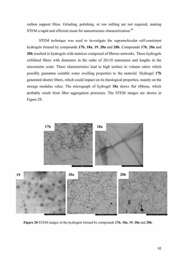
42
carbon support films. Grinding, polishing, or ion milling are not required, making
STEM a rapid and efficient mean for nanostructure characterization.88
STEM technique was used to investigate the supramolecular self-consistent
hydrogels formed by compounds 17b, 18a, 19, 20a and 20b. Compounds 17b, 20a and
20b resulted in hydrogels with matrices composed of fibrous networks. These hydrogels
exhibited fibers with diameters in the order of 28±10 nanometer and lengths in the
micrometer scale. These characteristics lead to high surface to volume ratios which
possibly guarantee suitable water swelling properties to the material. Hydrogel 17b
generated shorter fibers, which could impact on its rheological properties, mainly on the
storage modulus value. The micrograph of hydrogel 18a shows flat ribbons, which
probably result from fiber aggregation processes. The STEM images are shown in
Figure 28.
Figure 28 STEM images of the hydrogels formed by compounds 17b, 18a, 19, 20a and 20b.
17b 18a
19 20a 20b
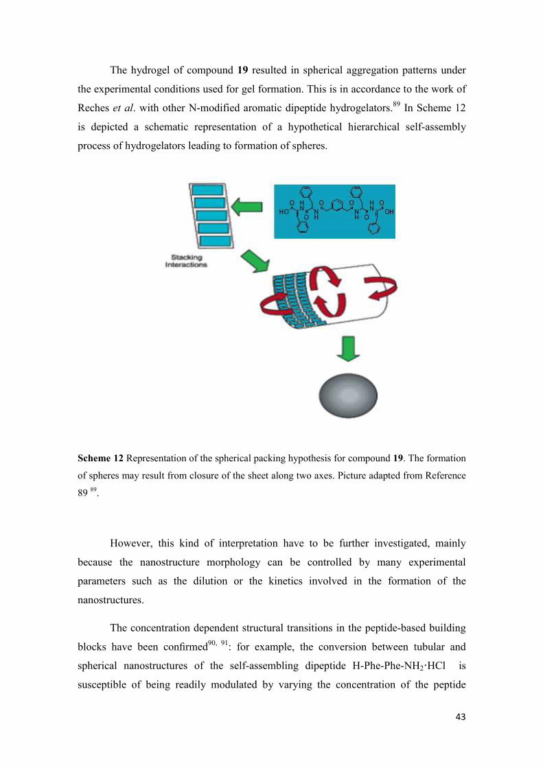
43
The hydrogel of compound 19 resulted in spherical aggregation patterns under
the experimental conditions used for gel formation. This is in accordance to the work of
Reches et al. with other N-modified aromatic dipeptide hydrogelators.89 In Scheme 12
is depicted a schematic representation of a hypothetical hierarchical self-assembly
process of hydrogelators leading to formation of spheres.
Scheme 12 Representation of the spherical packing hypothesis for compound 19. The formation
of spheres may result from closure of the sheet along two axes. Picture adapted from Reference
89 89.
However, this kind of interpretation have to be further investigated, mainly
because the nanostructure morphology can be controlled by many experimental
parameters such as the dilution or the kinetics involved in the formation of the
nanostructures.
The concentration dependent structural transitions in the peptide-based building
blocks have been confirmed90, 91: for example, the conversion between tubular and
spherical nanostructures of the self-assembling dipeptide H-Phe-Phe-NH2·HCl is
susceptible of being readily modulated by varying the concentration of the peptide
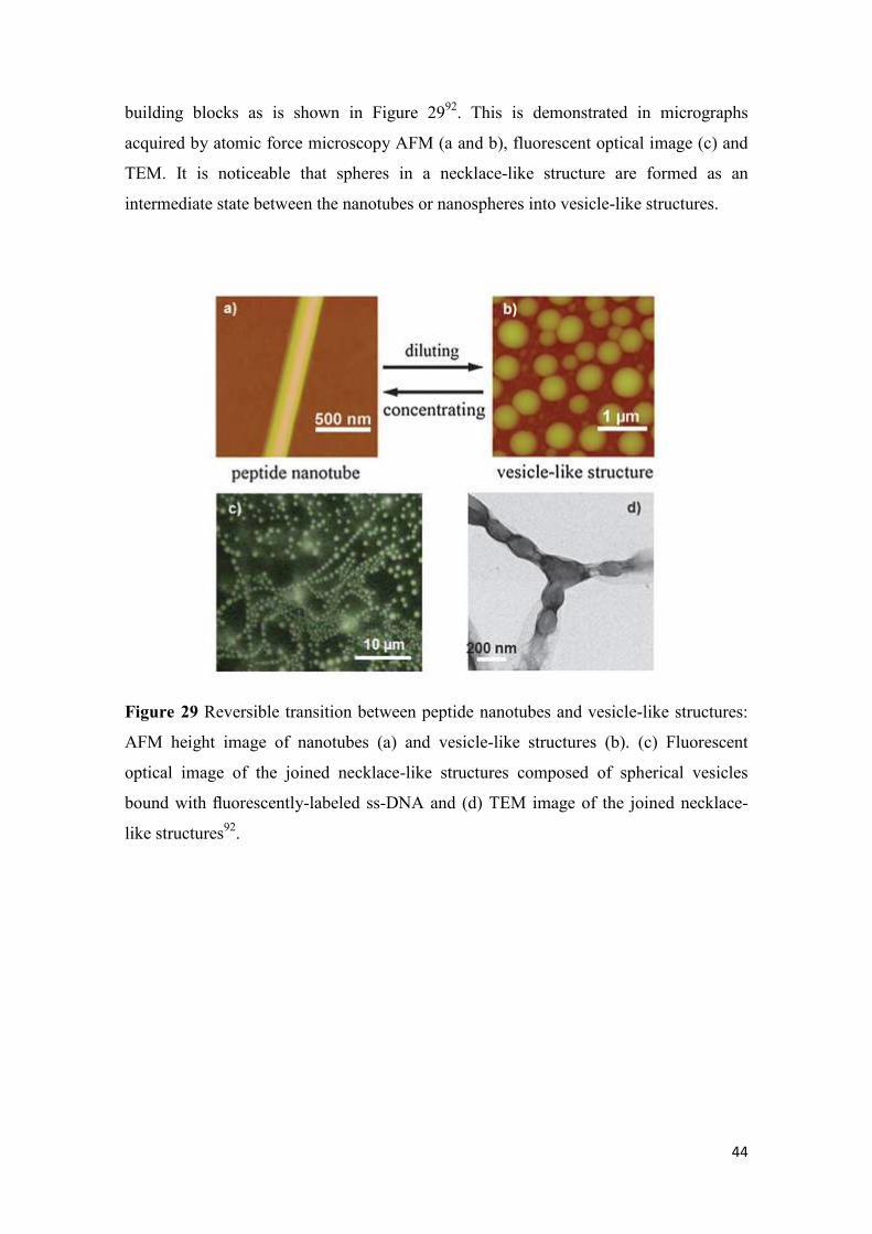
44
building blocks as is shown in Figure 2992. This is demonstrated in micrographs
acquired by atomic force microscopy AFM (a and b), fluorescent optical image (c) and
TEM. It is noticeable that spheres in a necklace-like structure are formed as an
intermediate state between the nanotubes or nanospheres into vesicle-like structures.
Figure 29 Reversible transition between peptide nanotubes and vesicle-like structures:
AFM height image of nanotubes (a) and vesicle-like structures (b). (c) Fluorescent
optical image of the joined necklace-like structures composed of spherical vesicles
bound with fluorescently-labeled ss-DNA and (d) TEM image of the joined necklace-
like structures92.
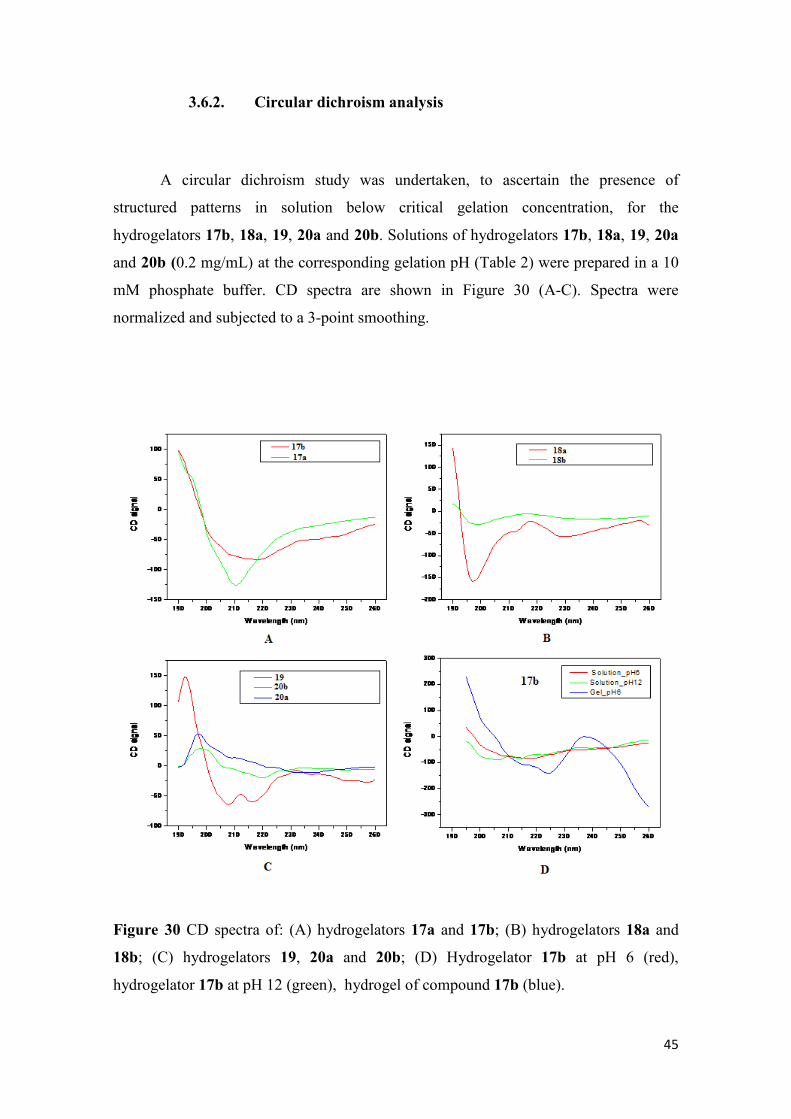
45
3.6.2. Circular dichroism analysis
A circular dichroism study was undertaken, to ascertain the presence of
structured patterns in solution below critical gelation concentration, for the
hydrogelators 17b, 18a, 19, 20a and 20b. Solutions of hydrogelators 17b, 18a, 19, 20a
and 20b (0.2 mg/mL) at the corresponding gelation pH (Table 2) were prepared in a 10
mM phosphate buffer. CD spectra are shown in Figure 30 (A-C). Spectra were
normalized and subjected to a 3-point smoothing.
Figure 30 CD spectra of: (A) hydrogelators 17a and 17b; (B) hydrogelators 18a and
18b; (C) hydrogelators 19, 20a and 20b; (D) Hydrogelator 17b at pH 6 (red),
hydrogelator 17b at pH 12 (green), hydrogel of compound 17b (blue).
46
CD spectra were acquired in the wavelength range 195-260 nm. In this spectral
window, CD signals resulting mainly from absorbances of the peptide bonds, are
expected.
Compound 17a shows the CD amide absorption (around 210 nm), at a lower
wavelength than compound 17b (215 nm) suggesting that, under these experimental
conditions, non-hydrogelating compound 17a displays less ordered structures in
solution than hydrogelator 17b. Based on the shape of its spectra, compound 17b seems
to have propensity for aggregating into β-sheets.
The CD spectrum for hydrogelator 18a shows that the concentration used in this
experiment is insufficient to produce any aggregation pattern. This could reflect the fact
that this hydrogelator displays the highest critical gelation concentration (0.8%).
On the other hand, compound 19, which displays the lowest cgc (0.3%), showed
strong evidence of aggregating into an α-helical pattern. As expected, compound 18b,
which failed to form hydrogel, does not shows evidence of any organized structures.
The CD spectra of the compounds 20a and 20b show an amide absorption in the
wavelength range from 205 to 220 nm suggesting the presence of some kind of pre-
organized nanostructures in solution, probably β-sheet packing, under this set of
experimental conditions.
Besides these experiments, compound 17b was also evaluated at its cgc, as gel,
and at pH 12 (Fig. 26 D). The hydrogel 17b was adjusted to pH 12 by treatment with
aqueous NaOH 1 M, resulting in a solution of 17b at a concentration similar to its cgc.
According to these data, we can infer that at basic pH there are no pre-organized
structures. This is in accordance to the fact that at pH 12 the hydrogelator molecules are
mostly deprotonated. In these conditions electrostatic repulsion prevails making
hydrogelator molecules more prone to aqueous solvation rather than undergoing self-
assembly. The CD spectrum for the hydrogel of 17b reveals the presence of more
organized structures possibly self-assembly into a β-sheet pattern.
47
4. Conclusions and Future Perspectives
In this work we have synthesized a small library of novel chemically diverse N-
dehydrodipeptides designed as novel hydrogelators. The ability of the members of the
library to form hydrogels was evaluated. It was found that five, out of seven compounds
tested, were able to self-assemble into a water swelling network giving self-consistent
pH-controlled hydrogel materials. STEM microscopy revealed that the hydrogels are
composed of fibers, ribbons and even spheres. The results also suggest that a spacer
between the organic modifier and the dipeptide moiety could lead to lower cgc´s.
The preliminary CD study, that was performed to ascertain the degree of
organization of the hydrogelator molecules, suggested that at extremely high pH, there
are no pre-organized structures and the hydrogelators presented some kind of
organizational pattern in the tested conditions, specially the compound 19 probably due
to its lowest cgc. The non-hydrogelating ones didn´t show any ordered pattern.
Mechanical characterization, which can elucidate the rheological behavior of the
hydrogels and a deeper investigation of their supra-molecular organization are essential
to direct the use of these hydrogels into new devices.
A future perspective for this work is to combine the experimental data developed
around the synthesized molecules with molecular modeling techniques, especially
molecular dynamics, in order to have more insight into the understanding about the
driving forces involved in the self-assembly process of these low molecular weight
hydrogelators.
48
5. Experimental Section
All the reagents were commercially acquired with a high level of purity and were
used without any kind of pre-treatment.
Melting points (ºC) were determined in a Gallenkamp apparatus and are
uncorrected. 1H and 13C-NMR spectra were recorded on a Varian Unity Plus at 300 and
75.4 MHz, respectively or on a Bruker Avance II+ at 400 and 100.6 MHz, respectively. 1H-1H spin-spin decoupling, bidimensional NMR techniques (HMBC, HSQC) and
DEPT θ 45º were used. Chemical shifts are given in ppm and coupling constants in Hz.
MS and HRMS data were recorded by the mass spectrometry service of the University
of Vigo, Spain; elemental analysis was performed on a Leco CHNS 932 elemental
analyser.
The reactions were monitored by thin layer chromatography (t.l.c.) in Merck-
Kieselgel 60 F254 plates. T.l.c were revealed with an UV lamp (ν = 50 Hz) in a UV
chamber CN-6 or with iodine. Column chromatography was performed on silica gel
MN Kieselgel 60 M 230-400 mesh. Petroleum ether refers to the boiling range 40-60
ºC. When solvent gradient was used, the increase of polarity was made from neat
petroleum ether to mixtures of ethyl acetate/petroleum ether, with increasing steps of
10% of ethyl acetate, until the isolation of the product was accomplished.
The dry toluene was commercially acquired and the DCM, acetonitrile and THF
were dried using the standards procedures described in Vogel's Textbook of Practical
Organic Chemistry93. Briefly, DCM was, at first, treated with calcium chloride (CaCl2)
and calcium hydride (CaH2) and then distillated. The acetonitrile was treated with silica
and calcium hydride (CaH2), distilled and stored with molecular sieves. The THF was
mixtured with thin slices of metallic sodium for 24 hours and next it was refluxed with
benzophenone until the media got in a blue-purple color. Next, it was distilled and
stored with molecular sieves.
The hydrogel preparation was accomplished by weighting the appropriate amount of
the final modified dipeptides into 2 mL glass vials and then 300µL of distilled water
was added. The samples were submitted to sonication for 60s. Next, drops of 10 µL of a
NaOH 0,5 M solution was added until the suspended solid was completely dissolved. In
49
this step, a vortex was used to mix the system more efficiently. Then, drops of 10 µL of
HCl 0,1M solution were added, carefully and followed by mixing, until media reach the
gelation point. The final pH values were estimated by putting a spatula tip of the
hydrogel onto a tape of universal indicator paper and then this pH values were précised
using a Crison Micro TT 2050 pHmeter.
The STEM analysis was performed using the microscopy service of the University
of Minho (Guimarães) and the CD spectra were recorded in the University of Coimbra.
5.1. Synthesis of dehydroamino acid derivatives 8a and 8b.
5.1.1. Synthesis of H-L-Thr-OMe·HCl (3a):
A 250 mL reaction flask containing methanol (1ml/mmol of aa, 50mL) was cooled with
an ice bath and then SOCl2 (3.4 eq., 170 mmol, 42.5 ml) was added, drop-wise, under
stirring. Next, the H-L-Thr-OH (50 mmol, 5.96 g) was slowly joined and the reaction
was kept under a 40°C reflux for 4 hours. Then the solvent was evaporated and resulted
in an transparent oil with 80% yield. It was not possible to crystallize the product.
1H-NMR (400 MHz, DMSO): δ = 1.19 (d, 3H, J= 6.6 Hz, CH3); 3.72 (s, 3H, OCH3);
3.89 (m, 1H, β-CH); 4.10 (m, J = 6.6, 3.9 Hz, 1H, α-CH); 5.02 (br s, 1H, β-OH); 8.53-
8.47 (m, 3H, NH3+).
5.1.2. Synthesis of H-DL-Phe(β-OH)-OMe·HCl (3b):
A 250 mL reaction flask containing 50 mL of methanol (1mL/mmol of the a.a) was
cooled with an ice bath and then SOCl2 (3.4 eq., 170 mmol, 42.5 mL) was added, drop-
wise, under stirring. Next, the H-DL-Phe(β-OH)-OH (50 mmol, 9.06g) was slowly
50
joined and the reaction was kept under a 40°C reflux for 4 hours. Then the solvent was
evaporated and the resulting material was recrystallized from methanol/diethyl ether. A
white solid with 100% yield was obtained.
1H-NMR (400 MHz, DMSO): δ = 3.60 (s, 3H, OCH3); 4.13 (d, 1H, J = 5.6 Hz; α-CH);
5.01 (d, 1H, J = 5.6 Hz; β-CH); 6.60-6.53 (br s, 1H, β-OH); 7.31-7.40 (m, 5H, H-Ar);
8.50 (br s, 3H, NH3+).
5.1.3. Synthesis of Boc-L-Phe-OH94
(4):
L-Phe-OH (50 mmol; 8.26 g) was dissolved in a mixture of dioxane (100 mL), water
(50 mL) and a solution of NaOH 1M (1.0 eq., 50 mmol, 50 mL) under vigorous stirring.
The system was cooled with an ice bath and then Boc2O (1.1 eq., 55 mmol, 12.00 g)
was added. After stirring at room temperature for 4 hours, the dioxane was evaporated
and the resulting material was cooled in a water bath. Ethyl acetate (100 mL) was added
to the reaction vial and the pH was adjusted to 2 by using a solution of KHSO4 1M (60
mL). The aqueous phase was extracted with ethyl acetate (2x 30 mL). All the organic
phases were gathered and washed with water (2x 30 mL), dried over MgSO4 and
evaporated under reduced pressure to give transparent oil that was crystallized in ethyl
acetate/hexane giving a white solid with quantitative yields.
1H-NMR (300 MHz, DMSO): δ = 1.306 (s, 9H, C(CH3)3); 2.850-2.770 (dd, 1H, J =
10.2 and 13.7 Hz; β-CH2); 2.976-3.037 (dd, 1H, J = 4.5 and 13.7 Hz; β-CH2); 4.091 (m,
1H, α-CH); 7.064-7.091 (d, 1H, J = 8.1Hz; N-H); 7.161-7.291 (m, 5H, H-Ar); 12.60 (br
s, 1H, OH).
51
5.1.4. Synthesis of Boc-L-Phe-L-Thr-OMe (5a):
Boc-L-Phe–OH (1.0 eq., 12.1 mmol, 3.2 g) was dissolved in acetonitrile (30 mL) and
immersed in an ice bath. HOBt (1.0 eq., 12.1 mmol, 1.64 g), DCC (1.2 eq., 14.5 mmol,
3.0 g), H-L-Thr-OMe (1.0 eq., 12.1 mmol, 2.05 g) and triethylamine (2.0 eq., 24.2
mmol, 3.37 mL) were added, waiting about 2 minutes between each addiction. The
mixture was left stirring overnight. Next, the reaction was filtered to exclude the DCU
(dicyclohexyl urea) and the liquid was evaporated under reduced pressure. Then 60 mL
of acetone was added and the flask was stored in the freezer for 3 hours to precipitate
more DCU. So the reaction is filtered again and the liquid was evaporated again. To the
resulting yellow oil 80 mL of ethyl acetate was added and this organic phase was
washed successively with aqueous KHSO4 1M (3x 30 ml), NaHCO3 1M (3x 30 mL)
and saturated NaCl (3x 30 ml) solutions. The organic phase was dried over anhydrous
MgSO4 and the solvent removed in vacuum. The compound 6a was obtained as 52%.
1H-NMR (400 MHz, CDCl3): δ = 1.150-1.172 (d, 3H, 6.6 Hz; CH3); 1.391 (s, 9H,
C(CH3)3); 2.987-3.057 (dd, 1H, J = 13.7 and 6.3 Hz; β-CH2); 3.108-3.175 (dd, 1H, J=
13.7 and 6.3 Hz; β-CH2); 3.719 (s, 3H, OCH3); 4.287 (br s, 1H, β-CH); 4.390-4.460
(m,1H, α-CH); 4.563-4.602 (dd, 1H, J = 6.3 and 9.0 Hz; α-CH); 5.160-5.185 (d, 1H, J=
7.5 Hz; N-H ); 6.881-6.911 (d, 1H, J= 9.0 Hz; N-H); 7.208–7.284 (m, 5H, H-Ar).
5.1.5. Synthesis of Boc-L-Phe-DL-Phe(β-OH)-OMe (5b):
Boc-L-Phe–OH (1.0 eq., 12.3 mmol, 3.3 g) was dissolved in acetonitrile (30 mL) and
immersed in an ice bath. HOBt (1.0 eq., 12.3 mmol, 1.66 g), DCC (1.2 eq., 14.7 mmol,
3.04 g), H-DL-Phe(β-OH)-OMe (1.0 eq., 12.3 mmol, 2.84 g) and triethylamine (2.0 eq.,
24.6 mmol, 3.42 mL) were added, waiting about 2 minutes between each addiction. The
mixture was left stirring overnight. Next, the reaction was filtered to exclude the DCU
(dicyclohexyl urea) and the liquid was evaporated under reduced pressure. Then 60 mL
of acetone was added and the flask was stored in the freezer for 3 hours to precipitate
52
more DCU. So the reaction is filtered again and the liquid was evaporated again. To the
resulting yellow oil 80 mL of ethyl acetate was added and this organic phase was
washed successively with aqueous KHSO4 1M (3x 30 ml), NaHCO3 1M (3x 30 mL)
and saturated NaCl (3x 30 ml) solutions. The organic phase was dried over MgSO4
anhydrous and the solvent removed in vacuum. The compound 6a was obtained as a
diasteroisomeric mixture with a 78% yield.
1H-NMR (400 MHz, CDCl3): δ = 7.33-7.23 (m, 10 H, H-Ar), 7.04 (dd, J = 7.3, 1.9 Hz,
1H), 6.87 and 6.71 (d, J = 8.8 Hz, 1H), 5.24 – 5.17 (br s, 1H, OH), 4.93 – 4.81 (m, 1H,
α H Phe), 4.33-4.36 (m, 1H, α H Phe (β-OH) ), 3.68 and 3.71 (s, 3 H, OCH3), 3.19 (d, J
= 4.2 Hz, 1H, β H Phe (β-OH)), 3.09 – 2.96 (m, 1H, β H Phe), 2.92 – 2.85 (m, 1H, β H
Phe), 1.40 (s, 9H, C(CH3)3).
5.1.6. Synthesis of Boc-L-Phe-∆Abu-OMe (7a):
Boc-L-Phe-(L)-Thr-OMe (6.21 mmol, 2.36 g) was dissolved in 15 mL of dry
acetonitrile and the. DMAP (0.11 eq, 0.68 mmol, 0,083g), Boc2O (1.1 eq., 6.83 mmol,
1.49g) were added under stirring at room temperature. The reaction flask was sealed
with a CaCl2 tube and the synthesis has been followed by 1H-NMR. After proving that
the initial material was converted to Boc-L-Phe-L-Thr-(β-Boc)-OMe, TMG (0,02
mL/mL of solvent; 0,3 mL) was joined to the reaction. After 24 hours there was
evidence, by 1H-NMR, that all the material was converted into the product 7a. The
solvent was evaporated and the orange resulting oil was dissolved in ethyl acetate (80
ml). This organic phase was washed successively with aqueous KHSO4 1M (3x 30 ml),
NaHCO3 1M (3x 30 mL) and saturated NaCl (3x 30 ml) solutions. The organic phase
was dried over anhydrous MgSO4 and the solvent removed in vacuum. A yellow solid
(1.52 g; 71%) was obtained.
1H-NMR (400 MHz, CDCl3): δ = 7.37-7.21 (m, 6H, H-Ar), 6.80 (q, J = 7.2 Hz, 1H, β
H ∆Abu), 5.00 (br s, 1H, α NH Phe ), 4.48 (m, 1H, α NH Phe), 3.74 (s, 3H, OCH3),
3.16-3.21 (dd, 1H, J = 14.0 and 6.4 Hz, β H Phe), 3.06-3.11 (dd, 1H, J = 14.0 and 7.2
Hz, β H Phe), 1.70 (d, J = 7.2 Hz, 3H, β CH3 ∆Abu), 1.43 (s, 9H, C(CH3)3) ppm.
53
5.1.7. Synthesis of Boc-L-Phe-∆Phe-OMe (7b):
The procedure described above was followed with compound 6b (9.32 mmol; 4.12 g)
giving the product 7b (86%; 2.90 g) as a yellow solid.
1H-NMR (400 MHz, CDCl3): δ = 7.67 (s, 1H, α NH ∆Phe), 7.42-7.21 (m, 11H, H-Ar
+ β H ∆Phe), 5.01-4.94 (m, 1H, α NH Phe), 4.14 – 4.06 (m, 1H, α H Phe), 3.83 (s, 3H,
OCH3), 3.21 (dd, J = 14.0, 6.6 Hz, 1H), 3.08 (dd, J = 14.0, 7.2 Hz, 1H), 1.41 (s, 9H,
C(CH3)3) ppm.
5.1.8. Synthesis of H-L-Phe-Z-∆Abu-OMe,TFA (8a):
Boc-(L)-Phe-∆Abu OMe , 7a, (4.8 mmol, 1.74 g) was dissolved in TFA (3 mL/mmol;
14.4 mL) and the reaction stayed under stirring for 3 hours when there was evidence, by
following the process with TLC (with ethyl acetate as eluent), that all the reactant 7a
had been consumed, giving the compound 8a (87 %, 1.56 g) as an yellow oil. 1H-NMR (400 MHz, DMSO): δ = 1.60 (d, 3 H, J = 7.2 Hz, γCH3 ∆Abu), 2.99-3.05
(dd, 1 H, J = 14.0 and 8.0 Hz, βCH2), 3.14-3.19 (dd, 1 H, J = 14.0 and 6.0 Hz, βCH2
Phe), 3.66 (s, 3 H, OCH3), 4.18-4.20 (m, 1 H, αCH Phe), 6.60 (q, 1 H, J = 7.2 Hz, βCH
∆Abu), 7.27-7.34 (m, 5 H, HAr), 8.29 (s br, 3 H, αNH3+), 9.89 (s, 1 H, αNH ∆Abu)
ppm. 13
C-NMR (100.6 MHz, DMSO): δ = 13.45 (γCH3 ∆Abu), 37.04 (βCH2 Phe), 52.00
(OCH3), 53.41 (αCH Phe), 126.71 (αC), 127.22 (CH), 128.57 (CH), 129.57 (CH),
133.68 (βCH ∆Abu), 134.74 (C), 164.11 (C=O), 167.22 (C=O) ppm. HRMS
(micrOTOF): calcd. for C14H19N2O3 263.13902; found 263.13925.
54
5.1.9. Synthesis of H-L-Phe-Z-∆Phe-OMe,TFA (8b):
The general procedure described above was followed using compound 7b (1.95 mmol,
0.862 g) giving compound 3a (92 %, 0.79g) as a white solid, m.p. 87.0-88.0ºC. 1H-NMR (400 MHz, DMSO): δ = 2.94–3.00 (dd, 1 H, J = 14.0 and 8.8 Hz, βCH2 Phe),
3.24–3.29 (dd, 1 H, J = 4.8 and 14.0 Hz, βCH2 Phe), 3.73 (s, 3H, OCH3), 4.25 (m, 1H,
αCH Phe), 7.30–7.41 (m, 9 H, ArH and βCH ∆Phe), 7.58-7.60 (dd, J = 2.0 and 4.0 Hz,
2 H, ArH), 8.26 (s br, 3 H, NH3+), 10.37 (s, 1 H, NH ∆Phe) ppm.
13C-NMR (100.6 MHz, DMSO): δ = 36.69 (βCH2 Phe), 52.37 (OCH3), 53.61 (αCH
Phe), 125.03 (αC), 127.31 (CH), 128.64 (CH), 128.71 (CH), 129.57 (CH), 129.72 (CH),
130.01 (CH), 132.31 (βCH ∆Phe), 132.83 (C), 134.80 (C), 164.87 (C=O), 168.30 (C=O)
ppm. HRMS (micrOTOF): calcd. for C19H21N2O3 325.15467; found 325.15545.
5.2. Coupling of the dehypeptides to the organic modifiers.
5.2.1. Synthesis of compound 13a:
To a stirred solution of trimesoyl chloride (72 mg, 0.27 mmol) in dry THF (5 mL),
triethylamine (7.0 eq., 1.89 mmol, 0.27 mL) was added and then H-L-Phe-Z-
∆Abu-OMe,TFA, 8b, (3.5 eq., 0.95 mmol, 357.2 mg) was added under nitrogen
atmosphere. This mixture was stirred for 1 h at room temperature and then refluxed
for 48 h under 80°C. The reaction was filtered; the solid was, separately, washed with
water and proved to be just Et3NHCl (because the entire solid was dissolved in water).
The filtered organic THF phase was evaporated and 50 mL of CH2Cl2 was added to the
resultant material. This organic solution was successively washed with aqueous KHSO4
1M (2x 10 ml), NaHCO3 1M (2x 10 mL) and Brine (2x 10 ml) solutions. The organic
phase was dried over anhydrous MgSO4 and the solvent removed under reduced
pressure. In order to crystallize the material, 30 mL of ethyl acetate was added and this
suspension was stored in the freezer for 24h. The suspension was filtered and the
compound 13a was obtained as a white solid that was washed with ethyl ether and dried
under vacuum. Yield: 52%; mp: 231 – 233°C.
55
1H-NMR (400 MHz, DMSO-d6): δ = 1.646-1.664 (d, 9 H, J = 7.2 Hz, γCH3 ∆Abu),
3.037-3.097 (dd, 3 H, J = 13.6 and 10.4 Hz, βCH2), 3.162- 3.206 (dd, 3 H, J = 4.4 and
13.6 Hz, βCH2 Phe), 3.632 (s, 9 H, OCH3), 4.901-4.908 (m, 3 H, αCH Phe), 6.552-
6.570 (q, 1 H, J = 7.2 Hz, βCH ∆Abu), 7.224-7.2614 (t, 3H, J=7.2 Hz, H-pAr), 7.136-
7.173 (m, 6 H, H-mAr), 7.364-7.382 (d, 6 H, J= 7.2 Hz, H-oAr), 8.35 (s, 3H, H-Ar;
central ring), 8.903-8.924 (d, 3H, J= 8.4 Hz, αNH Phe), 9.546 (s, 3 H, αNH ∆Abu) ppm.
13C-NMR (100.6 MHz, DMSO): δ = 13.49 (γCH3 ∆Abu), 37.26 (βCH2 Phe), 51.85
(OCH3), 54.91 (αCH Phe), 127.65 (αC), 126.29 (CH), 128.10 (CH), 129.19 (2 CH),
132.73 (βCH ∆Abu), 134.25 (C), 138.04 (C); 164.54 (C=O), 165.45 (C=O), 170.37
(C=O) ppm.
HRMS (ESI): calcd. for C51H54N6O12 942.37997; found 943.39039 [M+1].
5.2.2. Synthesis of compound 13b:
To a stirred solution of trimesoyl chloride (72 mg, 0.27 mmol) in dry THF (5 mL),
triethylamine (7.0 eq., 1.89 mmol, 0.27 mL) was added and then H-(L)-Phe-Z-
∆Phe-OMe,TFA, 8b, (3.5 eq., 0.95 mmol, 413.8 mg) was gathered under nitrogen
atmosphere. This mixture was stirred for 1 h at room temperature and then refluxed
for 48 h under 80°C The white precipitate was filtered and washed several times with
cold water to remove the byproduct Et3NHCl and finally with ethyl ether. This white
solid was dried under vacuum. Yield: 46%; mp: 272 – 275°C.
1H-NMR (400 MHz, DMSO-d6): δ = 3.081-3.111 (dd, 3H, J =13.7 and 10.4 Hz, β-
CH2 ); 3.22-3.249 (dd, 3H, J =13.7 and 4.1 Hz , β-CH2 ); 3.704 (s, 9H, OCH3);
4.912-4.965 (m, 3H, α-CH); 7.156-7.192 (t, 3H, J = 7.2 Hz); 7.247-7.278 (m,
6H, H-Ar; Phe); 7.278 (s, 3H, β-H; ∆Phe); 7.305-7.353 (m, 9H, H-Ar; ∆Phe);
7.404-7.423 (d, 6H, J =7.6 Hz, H-Ar; Phe); 7.660-7.678 (d, 6H, H-Ar; ∆Phe);
8.402 (m, 3H, H-Ar; central ring); 8.979 (d, 3H, J = 7.6 Hz; αNH Phe); 10.006
(s, 3H, αNH ∆Phe). 13
C-NMR (100.6 MHz, DMSO): δ = 36.58 (βCH2 Phe), 52.19 (OCH3), 55.13 (αCH
Phe), 125.97 (αC), 126.33 (CH), 128.15 (CH), 128.55 (CH), 129.18 (CH), 129.31 (CH),
56
129.46 (CH), 130.05 (CH), 131.97 (βCH ∆Phe), 133.22 (C), 134.33 (C), 138.14 (C),
165.34 (C=O), 165.75 (C=O), 171.38 (C=O) ppm.
HRMS (ESI): calcd. for C66H60N6O12 1128.42692; found 1129.43155 [M+1].
5.2.3. Synthesis of compound 14a:
To a stirred solution of terephtaloyl chloride (50.75 mg, 0.25 mmol) in dry THF (5
mL), triethylamine (5.0 eq., 1.25 mmol, 0.18 mL) and H-(L)-Phe-Z-∆Abu-OMe,
TFA, 8a, (2.4 eq., 0.6 mmol, 225.6 mg) were successively added under nitrogen
atmosphere. This mixture was stirred for 1 h at room temperature and then refluxed
for 48 h under 80°C. The reaction was filtered; the solid was, separately, washed with
water and proved to be just Et3NHCl because of its water solubility. The filtered organic
THF phase was evaporated and 50 mL of CH2Cl2 was added to the resultant material.
This organic solution was successively washed with aqueous KHSO4 1M (2x 10 ml),
NaHCO3 1M (2x 10 mL) and Brine (2x 10 ml) solutions. The organic phase was dried
over anhydrous MgSO4 and the solvent was removed under reduced pressure. In order
to crystallize the material, 30 mL of ethyl acetate was added and this suspension was
stored in the freezer for 24h. The suspension was filtered and the compound 13a was
obtained as a white solid that was washed with ethyl ether and dried under vacuum.
Yield: 67%; mp: 219 – 221°C.
1H-NMR (400 MHz, DMSO-d6): δ = 1.653-1.671 (d, 6 H, J = 7.2 Hz, γCH3 ∆Abu),
3.000-3.061 (dd, 2 H, J = 13.6 and 10.8 Hz, βCH2), 3.157-3.201 (dd, 2 H, J = 4.4 and
13.6 Hz, βCH2 Phe), 3.638 (s, 6 H, OCH3), 4.819-4.877 (m, 2 H, αCH Phe), 6.560-
6.578 (q, 1 H, J = 7.2 Hz, βCH ∆Abu), 7.234-7.272 (t, 3H, J = 7.2 Hz, H-pAr), 7.138-
7.175 (m, 4 H, H-mAr), 7.368-7.386 (d, 4 H, J = 7.2 Hz, H-oAr), 7.820 (s, 4H, H-Ar;
central ring), 8.740 (d, 2H, J = 8.4 Hz, αNH Phe), 9.498 (s, 2 H, αNH ∆Abu) ppm.
13C-NMR (100.6 MHz, DMSO): δ = 13.55 (γCH3 ∆Abu), 37.19 (βCH2 Phe), 51.93
(OCH3), 54.90 (αCH Phe), 127.65 (αC), 126.36 (CH), 127.34 (CH), 128.13 (CH),
129.24 (C), 132.86 (βCH ∆Abu), 136.33 (C), 138.20 (C); 164.60 (C=O), 165.75 (C=O),
170.54 (C=O) ppm.
HRMS (ESI): calcd. for C36H38N4O8 654.26896; found 655.27653 [M+1].
57
5.2.4. Synthesis of compound 14b:
To a stirred solution of trerephtaloyl chloride (50.75 mg, 0.25 mmol) in dry THF (5
mL), triethylamine (5.0 eq., 1.25 mmol, 0.18 mL) and H-(L)-Phe-Z-∆Phe-
OMe,TFA, 8b, (2.4 eq., 0.6 mmol, 262.8 mg) were successively added under
nitrogen atmosphere. This mixture was stirred for 1 h at room temperature and then
refluxed for 48 h under 80°C. The white precipitate was filtered and washed several
times with abundant cold water to remove the byproduct Et3NHCl and finally with ethyl
ether. This white solid was dried under vacuum. Yield: 59%; mp: 240 – 243°C.
1H-NMR (400 MHz, DMSO-d6): δ = 3.031-3.092 (dd, 2H, J = 13.8 and 3.9 Hz, β-
CH2 ); 3.207-3.242 (dd, 2H, J = 13.8 and 10.8 Hz, β-CH2 ); 3.703 (s, 6H, OCH3);
4.862 (m, 2H, α-CH); 7.157-7.345 (m, 16H, H-Ar); 7.681 (m, 4H, H-Ar; ∆Phe);
7.278 (s, 3H, β-H; ∆Phe); 7.305-7.353 (m, 9H, H-Ar; ∆Phe); 7.875 (s, 4H, H-Ar,
central ring); 8.844 (d, 2H, J = 8.0 Hz; αNH Phe); 9.963 (s, 2H, αNH ∆Phe). 13
C-NMR (100.6 MHz, DMSO): δ = 36.44 (βCH2 Phe), 52.23 (OCH3), 55.20 (αCH
Phe), 125.93 (αC), 126.35 (CH), 127.37 (CH), 128.13 (CH), 128.57 (CH), 129.21 (CH),
129.52 (CH), 130.13 (CH), 132.04 (βCH ∆Phe), 133.25 (C), 136.26 (C), 138.27 (C),
165.36 (C=O), 165.86 (C=O), 171.46 (C=O) ppm.
HRMS (ESI): calcd. for C46H42N4O8 778.30026; found 779.30759 [M+1]
5.2.5. Synthesis of compound 15:
5.2.5.1. Method 1:
This method uses the 2-2´-(1,3-phenylene) diacetic acid 21 and consisted in the
synthesis of one amide linkage per each single step and the dehydration process only
happens in the end of the synthetic route (Scheme 9).
58
5.2.5.1.1. Synthesis of 22:
The compound 21 (1.0 mmol, 0.1942 g) was dissolved in CH2Cl2 (10 mL) and
the system was cooled in an ice bath. Next, DCC (1.1 eq., 2.2 mmol. 0.453 g) and NHS
(1.1 eq., 2.2 mmol, 0.194 g) were added and the reaction was kept under stirring at
room temperature for 3 hours. Then this suspension was filtered and the organic phase
had its solvent evaporated. In another vial, the H-L-Phe-OH (1.1 eq., 2.2 mmol, 0.36 g)
was dissolved in water (10 mL) and NaHCO3 (2.3 eq. of the aa, 5 mmol, 0.34 mmol).
The material, that was evaporated before, was dissolved in acetone (5 mL) and added to
this aqueous reaction flask under vigorous stirring. The reaction was left reacting
overnight and after the acetone was evaporated, the aqueous phase was acidified with
aqueous HCl 1M until the pH got around 2. The reaction was filterd and resulted in a
gel. An aliquote of this material was dissolved in ethyl acetate and the mixture was put
in a separation funnel to exclude water from the material. The obtained organic phase
was dried over anydrous MgSO4 and evaporated. The final compound was isolated as
an oil that after 1H -NMR analyses revealed that the reaction was incomplete. So the rest
of the filtred gel was dissolved in a mixture of dioxane (10 mL), water (10 mL) and
aqueous NaOH 1M (2 mmol, 2 mL). This system was cooled in an ice bath, H-L-Phe-
OH (1.1 eq., 2.2 mmol, 0.36 g) was added again and the pH was adjusted to 9 using
aqueous NaOH 1M. The reaction was maintained under vigorous stirring at room
temperature overnight. Next, the dioxane was evaporated and ethyl acetate (100 mL)
was added to the reaction. The mixture was put in a separation funnel and aqueous
KHSO4 1M was added until the pH reached 2. The organic phase was dried under
anhydrous MgSO4 and the solvent was evaporated under reduced pressure. This resulted
in a pure white solid (87%, 0.424 g). mp. 145 – 146°C.
1H-NMR (300 MHz, DMSO-d6): 2.812-2.889 (dd, 2H, J = 13.8 and 9.3 Hz, CH2;
Phe), 3.013-3.075 (dd, 2H, J = 13.8 and 4.8 Hz, CH2; Phe), 3.314 (d, 2H, J = 10.5Hz,
CH2), 3.368 (d, 2H, J = 10.5Hz, CH2), 4.394-4.415 (m, 2H, αCH Phe), 6.930-7.270 (m,
14H, H-Ar), 8.339-8.366 (d, 2H, J = 8.1 Hz, N-H). 13
C-NMR (100.6 MHz, DMSO): δ= 36.777 (β CH2 Phe), 41.822 (CH2), 53.538 (α CH
Phe), 126.409 (CH), 126.863 (CH), 127.836 (CH), 128.171 (CH), 129.140 (CH),
129.899 (CH), 135.864 (C), 137.549 (C), 169.971 (C=O), 173.060 (C=O) ppm.
HRMS (ESI): calcd. for C28H28N2O6 488.19474; found 511.18432 [M + Na+].
59
5.2.5.1.2. Synthesis of 23:
The compound 22 (1.0 eq., 0.8 mmol, 0.39 g) was dissolved in acetonitrile (15 mL) and
immersed in an ice bath. HOBt (2.0 eq., 1.6 mmol, 0.22 g), DCC (2.2 eq., 1.76 mmol,
0.364 g), H-DL-Phe(β-OH)-OMe (2.0 eq., 1.6 mmol, 2.84 g) and triethylamine (4.4 eq.,
3.52 mmol, 0.5 mL) were added, waiting about 2 minutes between each addiction. The
mixture was left stirring overnight. Next, the reaction was filtered to exclude the DCU
and the liquid has been evaporated under reduced pressure. Then 60 mL of acetone was
added and the flask was stored in the freezer for 3 hours to precipitate more DCU. So
the reaction is filtered again and the liquid was evaporated. To the resulting yellow oil,
80 mL of ethyl acetate was added and this organic phase was washed successively with
aqueous KHSO4 1M (3x 30 ml), NaHCO3 1M (3x 30 mL) and saturated NaCl (3x 30
ml) solutions. The organic phase was dried over anhydrous MgSO4 and the solvent
removed in vacuum. It resulted in a white solid that was recrystalized from
dichloromethane/petroleum ether. The compound 6a was obtained as a disteroisomeric
mixture (44%, 0.30 g). This mixture was used with no purification in the next reaction
step.
HRMS (ESI): calcd. for C48H50N4O10 842.35269; found 843.35927 [M + 1].
5.2.5.1.3. Dehydration of 23:
The compound 23 (0.20 mmol, 0.165 g) was dissolved in 7 mL of dry acetonitrile.
DMAP (0.11 eq.0.04 mmol, 6 mg) and Boc2O (1.1 eq., 0.4 mmol, 0.105 g) were added
under stirring at room temperature. The reaction has been followed by 1H -NMR and
after proving that the initial material was all consumed, TMG (0,02 mL/mL of solvent;
0,14 mL) was joined to the reaction. After 24 hours there was evidence, by 1H –NMR,
that all the material was converted into the desirable product, 15, which precipitated in
the reaction media. So the reaction was filtrated and 59 mg of a solid was collected. The
organic liquid phase was evaporated and the resulting oil was dissolved in CH2Cl2 (50
ml) and this material was washed successively with aqueous KHSO4 1M (2x 30 ml),
and saturated NaCl (1x 50 ml) solutions. The organic phase was dried over anhydrous
60
MgSO4 and the solvent removed in vacuum. It was obtained an oil that was crystalized
from CH2Cl2/ petroleum ether. A white solid (99 mg; 62%) was obtained.
1H-NMR (300 MHz, DMSO-d6): 2.784-2.843 (dd, 2 H, J = 13.6 and 10.0 Hz, β CH2
Phe), 3.088-3.133 (dd, 2 H, J = 13.6 and 4.0 Hz, β CH2 Phe), 3.283 (d, 2H, J = 13.8 Hz,
CH2), 3.353 (d, 2H, J = 13.8 Hz, CH2), 3.684 (s, 6 H, OCH3), 4.649-4.703 (m, 2 H, α
CH), 6.860-6.879 (d, 2 H, J = 7.6 Hz, H-Ar; central ring), 6.891 (s, 1 H, H-Ar, central
ring), 6.995-7.032 (t, 1H, J = 7.6 Hz, H-Ar; central ring), 7.279 (s, 2 H, β H ∆Phe),
7.167-7.333 (m, 16 H, H-Ar, Phe + ∆Phe), 7.587-7.609 (m, 4 H, H-Ar, o-∆Phe), 8.415-
8.435 (d, 2 H, J = 8.0 Hz, αNH Phe), 9.896 (s, 2H, αNH ∆Phe).
13C-NMR (100.6 MHz, DMSO): δ = 37.14 (βCH2 Phe), 41.88 (CH2), 52.17 (OCH3),
54.09 (αCH Phe), 126.31 (CH), 126.75 (CH), 127.77 (CH), 128.07 (CH), 128.55 (CH),
129.22 (CH), 129.40 (CH), 129.96 (CH), 130.03 (CH), 131.90 (βCH ∆Phe), 125.98 (C),
133.24 (C), 135.86 (C), 137.76 (C), 165.40 (C=O), 170.04 (C=O), 171.46 (C=O) ppm.
HRMS (ESI): calcd. for C48H46N4O8 806.33156; found 807.33796 [M+1].
5.2.5.2.Method 2:
In a 50-mL round-bottom flask equipped with a stir bar and a condenser, containing 2-
2´-(1,3-phenylene)diacetic acid (0.097 g, 0.50 mmol) 21 thionyl chloride (117.03 mmol,
8.5 mL) was added with an addition funnel. Then four drops of DMF was gathered and
the reaction was kept under a 60 °C reflux for 6 hours. Then the excess of thionyl
chloride was evaporated and the resulting residue was dissolved in dry THF (5 mL).
Next, triethylamine (5.0 eq., 2.5 mmol, 0.35 mL) and H-L-Phe-Z-∆Phe-OMe,TFA,
8b, (2.4 eq., 1.2 mmol, 525.6 mg) were added under nitrogen atmosphere. This
mixture was stirred for 1 h at room temperature and then refluxed for 48 h under 80°C.
The white precipitate was filtered and washed several times with abundant cold water to
remove the byproduct Et3NHCl and finally with ethylic ether. This white solid was
dried under vacuum. Yield: 47%.
61
5.2.6. Synthesis of compound 16a:
To a stirred solution of diphenyl acetyl chloride (97.5 mg, 0.43 mmol) in dry THF (5
mL), triethylamine (2.5 eq., 1.07 mmol, 0.15 mL) and then H-L-Phe-Z-∆Abu-
OMe,TFA, 8b, (1.1 eq., 0.47 mmol, 175 mg) were added under nitrogen
atmosphere. This mixture was stirred for 48h at room temperature and then the
reaction was filtered, the solid was, separated, washed with water, to remove Et3NHCl,
and successively washed with aqueous KHSO4 1M (10 mL), NaHCO3 1M (10 mL) and
Brine (10 mL) and ethyl ether. The filtered organic THF phase was evaporated and 20
mL of ethyl acetate was added to the resultant material and the suspension was stored in
the freezer for 24h. The suspension was filtered and the solid was washed again
following the same procedure as had been done before. All the solids were pure and
corresponded to the compound 13a that was obtained as a white solid. Yield: 82%; mp:
173 – 175°C.
1H-NMR (400 MHz, DMSO-d6): δ = 1.555-1.573 (d, 3 H, J = 7.2 Hz, γCH3 ∆Abu),
2.791-2.849 (dd, 1 H, J = 13.6 and 9.6 Hz, βCH2), 3.034-3.081 (dd, 3 H, J = 4.8 and
13.6 Hz, βCH2 Phe), 3.593 (s, 3 H, OCH3), 4.711-4.769 (m, 1 H, αCH Phe), 5.029 (s,
1H, H-C(Phe)2) 6.501 (q, 1 H, J = 7.2 Hz, βCH ∆Abu), 6.973-6.996 (dd, 2H, J=7.2 and
1.6 Hz, H-mAr, Phe), 7.154-7.264 (m, 13 H, H-Ar), 8.609 (d, 1H, J = 8.4 Hz, αNH
Phe), 9.493 (s, 3 H, αNH ∆Abu) ppm.
13C-NMR (100.6 MHz, DMSO): δ = 13.35 (γCH3 ∆Abu), 37.83 (βCH2 Phe), 51.81
(OCH3), 53.76 (αCH Phe), 56.00 (C-(Phe)2), 127.59 (αC), 126.39 (CH), 128.01 (CH),
128.11 (CH), 128.40 (CH), 128.70 (CH), 129.27 (CH), 132.47(βCH ∆Abu), 137.43 (C),
140.07(C), 140.30 (C), 164.54 (C=O), 170.24 (C=O), 170.79 (C=O) ppm.
HRMS (ESI): calcd. for C28H28N2O4 456.20491; found 457.21191 [M + 1].
5.2.7. Synthesis of compound 16b:
To a stirred solution of diphenyl acetyl chloride (57.5 mg, 0.25 mmol) in dry THF (5
mL) was added triethylamine (2.5 eq., 0.63 mmol, 0.10 mL) and then H-L-Phe-Z-
∆Phe-OMe,TFA, 8b, (1.1 eq., 0.28 mmol, 120.5 mg) was added under nitrogen
62
atmosphere. This mixture was stirred for 48 h at room temperature and then the white
precipitate was filtered and washed several times with water to remove the byproduct
Et3NHCl and finally with aqueous KHSO4 1M (10 mL), NaHCO3 1M (10 mL) and
Brine (10 mL) and eyhyl ether. The filtered THF phase was taken apart and diethyl
ether was added and the dispersion was stored into the freezer for 24 h to precipitate
more product. This new solid was filtered and washed the same way as before. Both
solids were pure and corresponded to the desired product 16b. Yield: 71%; 197 –
198°C.
1H-NMR (400 MHz, DMSO-d6): δ = 2.778-2.838 (dd, 1H, J= 13.8 and 10.2 Hz,
βCH2); 3.073-3.118 (dd, 1H, J = 13.8 and 4.4 Hz, βCH2 ); 3.647 (s, 3H, OCH3); 4.746-
4.781 (m, 1H, α-CH); 5.002 (s, 1H, H-C(Phe)2); 6.953-6.977 (m, 2H, Phe), 7.144-7.312
(m, 17H, H-Ar + βH ∆Phe), 7.554-7.572 (d, 2H, J = 7.2 Hz, H-oAr; ∆Phe), 8.638 (d,
1H, J = 8.4 Hz, αNH Phe), 9.951 (s, 1 H, αNH ∆Phe) ppm.
13C-NMR (100.6 MHz, DMSO): δ = 37.41 (βCH2 Phe), 52.35 (OCH3), 54.10 (αCH
Phe), 56.14 (C-(Phe)2), 125.81 (αC), 126.49 (CH), 128.18 (CH), 128.20 (CH), 128.44
(CH), 128.71 (CH), 128.87 (CH), 129.36 (CH), 130.14 (CH), 132.33 (βCH ∆Phe),
133.23 (C), 137.62 (C), 140.11(C), 140.48 (C), 165.50 (C=O), 171.12 (C=O), 171.44
(C=O) ppm.
HRMS (ESI): calcd. for C33H30N2O4 518.22056; found 519.22815 [M + 1].
5.2.8. Synthesis of compound 24
5.2.8.1. Acetylation of the caffeic acid (CA):
In a 50-mL round-bottom flask, caffeic acid (5.5 mmol, 1 g) was dissolved in a solution
of NaOH 1M (15 mL) with magnetic stirring. To this solution, acetic anhydride (2 mL,
2.164 g, 21.2 mmol) was added. The reaction mixture was stirred for 30 minutes in an
ice bath. The impure solid product was isolated using vacuum filtration. The solid was
washed with a minimal amount of ice-cold distilled water. The crude product was
recrystalized by dissolving it in 15 mL of boiling ethanol (95%). The solution rested to
allow the solution to cool slowly to room temperature, and let the crystals form for half
63
an hour. The pure product was isolated using vacuum filtration after cooling in an ice
bath for 10 minutes. The product was left resting in an open vial for half an hour, in
order to dry. 1.27 g of a white solid was obtained with 87% yield. mp 190-192 oC. 1H-NMR (DMSO-d6): δ = 7.7 (br s, 1H, Har), 7.55 (d, 1H, J = 18.6 Hz, CHCar), 7.2 (d,
2H, J = 8.6 Hz, Har), 6.5 (d, 1H, J = 18.6 Hz, CHCO), 2.3 (s, 6H, 2 x OAc); 13
C-NMR (DMSO-d6): δ = 168.2, 168.1, 167.4, 143.3, 142.3, 142.2, 133.1, 126.7,
124.1, 123.0, 120.3, 20.4, 20.3; LRMS: 265.1, 205.1, 163.1, 145.1, 117.1, 89.1;
HRMS: calc. for C13H12O6 + (Na+): 287.0526; found: 287.0522.
5.2.8.2. Coupling of the diacetylated caffeic acyl chloride to the
dehydropeptide 8b
4 mL of thionyI chloride was slowly added to a 10-mL round-bottom flask equipped
with a stir bar and condenser, containing the diacetylcaffeic acid (0.47 mmol, 125 mg).
Then two drops of DMF was gathered to the reaction media and the reaction was kept in
a 60°C reflux for 4 hours. Then the excess of thionyl chloride was evaporated and the
resulting residue was dissolved in dry THF (5 mL). Next, triethylamine (1.25 eq.,
1.19 mmol, 0.17 mL) and H-L-Phe-Z-∆Phe-OMe,TFA, 8b, (1.1 eq., 0.52 mmol,
226.5 mg) were added under nitrogen atmosphere. This mixture was stirred for 1
h at room temperature and then refluxed for 24 h under 80°C. Then the reaction was
filtered to eliminate the triethylamonium chloride. The THF was evaporated and the
residue was dissolved in 100 mL of CH2Cl2. This solution was washed successively with
aqueous KHSO4 1M (4x 30 mL), NaHCO3 1M (1x 30 mL) and Brine (3x 30 mL). The
organic phase was dried over anhydrous MgSO4, filtered and evaporated under reduced
pressure. It was obtained an oil that crystallized in ethyl acetate/diethylic ether. After
filtration of the precipitate, it resulted in the product 24 as an orange solid (142 mg,
52%). 1H-NMR (DMSO-d6): δ = 2.273 (s, 3H, CH3-Ac), 2.280 (s, 3H, CH3-Ac), 2.829-2.889
(dd, 1H, J = 13.9, 10.2 Hz, β CH2), 3.140-3.186 (dd, J = 13.9, 4.3 Hz, 1H), 3.701 (s, 3H,
OCH3), 4.794-4.816 (ddd, J = 10.2, 8.2, 4.3 Hz, 1H, αCH), 6.670 (d, 1H, J = 15.8 Hz,
=CH), 7.173 – 7.215 (m, 1H, H-Ar), 7.255 (br s, 1H, βH ∆Phe), 7.279-7.402 (m, 9H,
=CH + H-Ar), 7.496 – 7.460 (m, 2H, H-Ar), 7.628 – 7.652 (m, 2H, H-Ar), 8.483 (d, 1H,
J = 8.4 Hz, αNH Phe), 9.940(s, 1H, αNH ∆Phe).
64
13C-NMR (100.6 MHz, DMSO): δ = 20.37 (CH3 Ac), 37.10 (βCH2 Phe), 52.24
(OCH3), 54.39 (αCH Phe), 125.92 (αC), 122.33 (CH), 122.82 (CH), 124.18 (CH),
125.94 (CH), 126.44 (CH), 128.18 (CH), 128.62 (CH), 129.21 (CH), 129.52 (CH),
130.13 (CH), 137.48 (CH), 132.05 (βCH ∆Phe), 133.22 (C), 133.69 (C), 137.80(C),
142.32 (C), 142.76 (C), 164.77 (C=O), 165.35 (C=O), 168.19 (C=O), 168.23 (C=O),
171.43 (C=O) ppm.
HRMS (ESI): calcd. for C32H30N2O8 570.20022; found 571.20805 [M + 1].
5.2.9. Synthesis of compound 26
5.2.9.1.Acetylation of the dihydrocaffeic acid (DHCA):
In a 50-mL round-bottom flask, dihydrocaffeic acid (5.5 mmol, 1 g) was dissolved in a
solution of NaOH 1M (15 mL) under magnetic stirring. To this solution, acetic
anhydride was added. The reaction mixture was stirred for 2 hours in an ice bath. An oil
was formed in the bottom of the reaction flask. The aqueous media was removed with a
Pasteur pipette and the excess of solvent was removed from the oil by evaporation
under reduced pressure. In the end, an slightly yellow oil was obtained (1.05 g, 72%). 1H-NMR (300 MHz, DMSO-d6): δ = 2.233 (s, 3H, OAc), 2.240 (s, 3H, OAc), 2.342 (t,
3H, J = 8.1 Hz, CH2), 2.775 (t, 3H, J = 8.1 Hz, CH2), 7.107-7.073 (m, 3H, Har).
5.2.9.2.Coupling of the diacetylated dihydrocaffeic acyl chloride to
the dehydropeptide 8b:
4 mL of thionyI chloride was slowly added to a 10-mL round-bottom flask equipped
with a stir bar and condenser, containing the diacetyldihydrocaffeic acid (0.47 mmol,
125 mg). Then two drops of DMF was gathered to the reaction media and the reaction
was kept under a 60°C reflux for 4 hours. Then the excess of thionyl chloride was
evaporated and the resulting residue was dissolved in dry THF (5 mL). Next,
triethylamine (1.25 eq., 1.19 mmol, 0.17 mL) and H-L-Phe-Z-∆Phe-OMe,TFA, 8b,
(1.1 eq., 0.52 mmol, 226.5 mg) were added under nitrogen atmosphere. This
65
mixture was stirred for 1 h at room temperature and then refluxed for 24 h under 80°C.
Then the reaction was filtered to eliminate the triethylamonium chloride. The THF was
evaporated and the residue was dissolved in 100 mL of CH2Cl2. This solution was
washed successively with aqueous KHSO4 1M (4x 30 mL), NaHCO3 1M (1x 30 mL)
and Brine (3x 30 mL). The organic phase was dried over anhydrous MgSO4, filtered
and evaporated under reduced pressure. It was obtained an oil that crystallized in ethyl
acetate/diethyl ether. After filtration of the precipitate, it resulted in the product 26 as an
orange solid (176 mg; 64%). 1H-NMR (400 Hz, DMSO-d6): δ = 2.228 (s, 3H, CH3-Ac), 2.231 (s, 3H, CH3-Ac),
2.371 (t, J = 7.9 Hz, 2H, CH2), 2.704 (t, J = 7.9 Hz, 2H, CH2), 2.829-2.889 (dd, 1H, J =
13.8, 10.2 Hz, β CH2), 3.085-3.130 (dd, J = 13.8, 4.4 Hz, 1H), 3.688 (s, 3H, OCH3),
4.652-4.709 (m, 1H, αCH), 7.004 – 7.057 (m, 2H, H-Ar), 7.189-7.207 (m, 2H, H-Ar),
7.247 (s, 1 H, βH ∆Phe), 7.265-7.362 (m, 7 H, H-Ar), 8.357 (d, 1H, J = 8.4 Hz, αNH
Phe), 9.922 (s, 1H, αNH ∆Phe). 13
C-NMR (100.6 MHz, DMSO): δ = 20.31 (CH3 Ac), 20.33 (CH3 Ac), 30.24 (CH2),
36.45 (CH2), 37.08 (βCH2 Phe), 52.16 (OCH3), 54.10 (αCH Phe), 125.96 (αC), 123.06
(CH), 123.19 (CH), 126.13 (CH), 126.30 (CH), 128.04 (CH), 128.53 (CH), 129.21
(CH), 129.45 (CH), 130.08 (CH), 131.99 (βCH ∆Phe ), 133.20 (C), 137.91 (C),
140.01(C), 140.08 (C), 141.65 (C), 165.35 (C=O), 168.16 (C=O), 168.27 (C=O), 171.30
(C=O), 171.58 (C=O) ppm.
HRMS (ESI): calcd. for C32H32N2O8 572.21587; found 595.20453 [M + Na+].
5.3. Basic hydrolysis of the methyl esters
The general procedure for the hydrolysis of the methyl esters groups was to dissolve the
proper amount of each compound into a mixture of dioxane (3 mL/0.1 mmol of the
ester) and aqueous NaOH 1M (1.5 eq. / each ester group) under vigorous stirring and at
room temperature. This process was followed by t.l.c. (eluent: ethyl acetate). When all
the initial reactant was consumed, the solvent was evaporated and 10 mL of KHSO4 1M
was added to the reaction vial to assure that the pH reached values around 2-3. This
system was kept at the freezer for 24 h and then the product was filtered, washed with
aqueous KHSO4 1M and with a minimum amount of diethyl ether. The solid obtained
was dried under vacuum.
66
5.3.1. Synthesis of compound 17a:
The general procedure described above was followed using compound 13a (0.075
mmol, 80 mg), giving compound 17a (82 %) as a white solid, that decomposes at
197°C. 1H-NMR (400 MHz, DMSO-d6): δ = 1.613-1.631 (d, 9 H, J = 7.2 Hz, γCH3 ∆Abu),
3.003-3.064 (dd, 3 H, J = 13.6 and 10.8 Hz, βCH2), 3.171-3.205 (dd, 3 H, J = 3.6 and
13.6 Hz, βCH2 Phe), 4.888-4.946 (m, 3 H, αCH Phe), 6.571-6.589 (q, 3 H, J = 7.2 Hz,
βCH ∆Abu), 7.130-7.166 (m, 6 H, H-mAr), 7.217-7.276 (t, 3H, J = 7.6 Hz, H-pAr),
7.357-7.375 (d, 6 H, J = 7.2 Hz, H-oAr), 8.293 (s, 3H, H-Ar; central ring), 8.804-8.825
(d, 3H, J = 8.4 Hz, αNH Phe), 9.373 (s, 3 H, αNH ∆Abu) ppm. 13
C-NMR (100.6 MHz, DMSO): δ = 13.72 (γCH3 ∆Abu), 39.34 (βCH2 Phe), 54.93
(αCH Phe), 128.14 (αC), 126.30 (CH), 128.11 (CH), 129.14 (2CH)*, 129.19, 132.43
(βCH ∆Abu), 134.32 (C), 138.09 (C); 165.45 (C=O), 165.47 (C=O), 170.10 (C=O)
ppm.
HRMS (ESI): calcd. for C48H48N6O12 900.33302; found 901.33976 [M + 1].
5.3.2. Synthesis of compound 17b:
The general procedure described above was followed using compound 13b (0.053
mmol, 60 mg) giving compound 17b (85 %, 49 mg) as a white solid, that decomposes at
224°C. 1H-NMR (400 MHz, DMSO-d6): δ = 3.016-3.078 (dd, 3H, J = 13.9 and 10.8 Hz,
βCH2 ); 3.016-3.078 (dd, 3H, J=13.9 and 4.0 Hz, βCH2 ); 4.886-4.943 (m, 3H,
αCH); 7.131-7.202 (t, 3H, J = 7.2 Hz); 7.220-7.354 (m, 15H, H-Ar); 7.298 (s,
3H, β-H; ∆Phe); 7.386-7.404 (m, 6H, H-Ar); 7.638-7.659 (m, 6H, H-Ar; ∆Phe);
8.341 (s, 3H, H-Ar; central ring); 8.899-8.920 (d, 3H, J = 8.4 Hz; αNH Phe);
9.819 (s, 3H, αNH ∆Phe). 13
C-NMR (100.6 MHz, DMSO): δ = 33.33 (βCH2 Phe), 55.16 (αCH Phe), 126.65 (αC),
126.29 (CH), 128.17 (CH), 128.48 (CH), 129.17 (2 CH), 129.23 (CH), 129.94 (CH),
131.84 (βCH ∆Phe), 133.56 (C), 134.35 (C), 138.22 (C), 165.71 (C=O), 166.18 (C=O),
171.08 (C=O) ppm.
HRMS (ESI): calcd. for C63H54N6O12 1086.37997; found 1087.38470 [M + 1].
67
5.3.3. Synthesis of compound 18a:
The general procedure described above was followed using compound 14a (0.153
mmol, 100 mg) giving compound 18a (68 %, 43 mg) as a white solid, that decomposes
at 190°C. 1H-NMR (400 MHz, DMSO-d6): δ = 1.626-1.644 (d, 6 H, J = 7.2 Hz, γCH3 ∆Abu),
3.994-3.056 (dd, 2 H, J = 13.6 and 10.0 Hz, βCH2), 3.157-3.201 (dd, 2 H, J = 4.0 and
13.6 Hz, βCH2 Phe), 4.827-4.886 (m, 2 H, αCH Phe), 6.575-6.593 (q, 2 H, J = 7.2 Hz,
βCH ∆Abu), 7.226-7.264 (t, 3H, J = 7.6 Hz, H-pAr), 7.375-7.394 (d, 4 H, J = 7.2 Hz,
H-oAr), 7.129-7.166 (m, 4 H, H-mAr), 7.814 (s, 4H, H-Ar; central ring), 8.706-8.727
(d, 2H, J = 8.4 Hz, αNH Phe), 9.353 (s, 2 H, αNH ∆Abu) ppm.
13C-NMR (100.6 MHz, DMSO): δ = 13.73 (γCH3 ∆Abu), 37.28 (βCH2 Phe), 54.94
(αCH Phe), 128.19 (αC), 126.28 (CH), 127.28 (CH), 128.06 (CH), 129.22 (C), 132.37
(βCH ∆Abu), 136.33 (C), 138.27 (C); 165.49 (C=O), 165.66 (C=O), 170.17 (C=O)
ppm.
HRMS (ESI): calcd. for C34H34N4O8 626.23766; found 627.24519 [M + 1].
5.3.4. Synthesis of compound 18b:
The general procedure described above was followed using compound 14b (0.077
mmol, 60 mg) giving compound 18b (78%, 45 mg) as a white solid, that decomposes at
218°C. 1H-NMR (400 MHz, DMSO-d6): δ =.3.015-3.077 (dd, 2H, J = 13.7 and 10.8 Hz,
βCH2 ); 3.207-3.242 (dd, 2H, J = 13.7 and 3.6, βCH2 ); 4.838-4.886 (m, 2H,
αCH); 7.143-7.334 (m, 14H, H-Ar + βCH ∆Phe ); 7.400-7.418 (d, 4H, J = 7.2
Hz, H-Ar; Phe); 7.651-7.669 (m, 4H, H-Ar; ∆Phe); 7.854-7.865 (m, 4H, H-Ar,
central ring); 8.786-8.807 (d, 2H, J = 8.4 Hz; αNH Phe); 9.789 (s, 2H, αNH
∆Phe). 13
C-NMR (100.6 MHz, DMSO): δ = 36.52 (βCH2 Phe), 55.24 (αCH Phe), 126.60 (αC),
126.30 (CH), 127.33 (CH), 128.09 (CH), 128.47 (CH), 129.21 (CH), 129.24 (CH),
130.02 (CH), 131.87 (βCH ∆Phe), 133.60 (C), 136.28 (C), 138.36 (C), 165.80 (C=O),
166.20 (C=O), 171.12 (C=O) ppm.
68
HRMS (ESI): calcd. for C44H38N4O8 750.26896; found 751.27670 [M + 1].
5.3.5. Synthesis of compound 19:
The general procedure described above was followed using compound 15 (0.081 mmol,
65 mg) giving compound 19 (64%, 40 mg) as a white solid, that decomposes at 198°C. 1H-NMR (300 MHz, DMSO-d6): 2.759-2.820 (dd, 2 H, J = 13.8 and 10.6 Hz, β CH2
Phe), 3.100-3.144 (dd, 2 H, J = 13.8 and 3.8 Hz, β CH2 Phe), 3.283 (d, 2H, J =13.8 Hz,
CH2), 3.353 (d, 2H, J = 13.8 Hz, CH2), 4.653-4.709 (m, 2 H, α CH), 6.822-6.841 (m, 3
H, H-Ar; central ring), 6.968-7.006 (t, 1H, J = 8 Hz, H-Ar; central ring), 7.280 (s, 2 H, β
H ∆Phe), 7.156-7.323 (m, 16 H, H-Ar, Phe + ∆Phe), 7.586-7.601 (m, 4 H, H-Ar, o-
∆Phe), 8.354-8.375 (d, 2 H, J = 8.4 Hz, αNH Phe), 9.713 (s, 2H, αNH ∆Phe). 13
C-NMR (100.6 MHz, DMSO): δ = 37.14 (βCH2 Phe), 41.88 (CH2), 54.07 (αCH
Phe), 126.26 (CH), 126.70 (CH), 127.73 (CH), 128.02 (CH), 128.11 (CH), 128.45 (CH),
129.18 (CH), 129.22 (CH), 129.92 (CH), 131.80 (βCH ∆Phe), 126.56 (C), 133.54 (C),
135.82 (C), 137.82 (C), 166.18 (C=O), 170.00 (C=O), 171.13 (C=O) ppm.
HRMS (ESI): calcd. for C46H42N4O8 778.30026; found 779.30758 [M + 1].
5.3.6. Synthesis of compound 20a:
The general procedure described above was followed using compound 16a (0.30 mmol,
136 mg) giving compound 20a (71%, 91.2 mg) as a white solid, that decomposes at
190°C. 1H-NMR (400 MHz, DMSO-d6): δ = 1.536-1.553 (d, 3 H, J = 6.8 Hz, γCH3 ∆Abu),
2.775-2.834 (dd, 2 H, J = 14.0 and 9.8 Hz, β CH2 Phe), 3.044-3.090 (dd, 2 H, J = 14.0
and 4.5 Hz, β CH2 Phe), 4.76 (ddd, 1 H, J = 9.8, 8.4, 4.5 Hz, α CH Phe), 5.016 (s, 1H,
H-C(Phe)2) 6.516-6.569 (q, 1 H, J = 7.2 Hz, βCH ∆Abu), 6.955-6.979 (m, 2H, H-mAr,
Phe), 7.152-7.283 (m, 13H, H-Ar), 8.501-8.522 (d, 1H, J = 8.4 Hz, αNH Phe), 9.298 (s,
3 H, αNH ∆Abu) ppm. 13
C-NMR (100.6 MHz, DMSO): δ = 13.61 (γCH3 ∆Abu), 37.92 (βCH2 Phe), 53.75
(αCH Phe), 56.02 (C-(Phe)2), 128.01 (αC), 126.21 (CH), 126.35 (CH), 126.55 (CH),
127.97 (CH), 127.98 (CH), 128.11 (CH), 128.40 (CH), 128.70 (CH), 129.28 (CH),
69
132.22 (βCH ∆Abu), 137.50 (C), 140.05 (C), 140.30 (C), 165.42 (C=O), 169.85 (C=O),
170.77 (C=O) ppm.
HRMS (ESI): calcd. for C27H26N2O4 442.18926; found 443.19717 [M + 1].
5.3.7. Synthesis of compound 20b:
The general procedure described above was followed using compound 16b (0.108
mmol, 50 mg) giving compound 20b (73%, 35 mg) as a white solid, that decomposes at
197°C. 1H-NMR (400 MHz, DMSO-d6): δ = 2.778-2.838 (dd, 1H, J = 13.8 and 10.8 Hz,
βCH2 ); 3.073-3.118 (dd, 1H, J = 13.8 and 4.0 Hz, βCH2 ); 4.755-4.812 (m, 1H,
α-CH); 4.995 (s, 1H, H-C(Phe)2); 6.932-6.952 (m, 2H, Phe), 7.148-7.299 (m, 17 H, H-
Ar + βH ∆Phe), 7.554-7.572 (dd, 2H, J = 7.2 and 1.2 Hz, H-oAr; ∆Phe), 8.569-8.590
(d, 1H, J = 8.4 Hz, αNH Phe), 9.773 (s, 1 H, αNH ∆Phe) ppm. 13
C-NMR (100.6 MHz, DMSO): δ = 37.28 (βCH2 Phe), 53.93 (αCH Phe), 56.00 (C-
(Phe)2), 126.35 (αC), 126.32 (CH), 127.97 (CH), 128.10 (CH), 128.30 (CH), 128.43
(CH), 128.75 (CH), 129.24 (CH), 129.88 (CH), 131.94 (βCH ∆Phe), 133.52 (C), 137.61
(C), 140.00 (C), 140.40 (C), 166.16 (C=O), 170.87 (C=O), 170.92 (C=O) ppm
HRMS (ESI): calcd. for C32H28N2O4 504.20491; found 505.21252 [M + 1].
70
6. Bibliography
1. de Loos, M.; Feringa, B. L.; van Esch, J. H. Eur.J.Org.Chem. 2005, 2005, 3615-3631.
2. Mitra, R. N.; Das, D.; Roy, S.; Das, P. K. Journal of Physical Chemistry B 2007, 111, 14107-14113.
3. Hamidi, M.; Azadi, A.; Rafiei, P. Advanced Drug Delivery Reviews 2008, 60, 1638-1649.
4. Almdal, K.; Dyre, J.; Hvidt, S.; Kramer, O. Polymer Gels and Networks 1993, 1, 5-17.
5. Peppas, N. A.; Khare, A. R. Advanced Drug Delivery Reviews 1993, 11, 1-35. 6. M. Hamidi, A. Azadi, P. Rafiei. Advanced Drug Delivery Reviews 60 (2008)
1638–1649. 7. Peppas, N. A.; Bures, P.; Leobandung, W.; Ichikawa, H. European Journal of
Pharmaceutics and Biopharmaceutics 2000, 50, 27-46. 8. Satish, C. S.; Kumar, C.; Narasimhamurthy, S.; Shivakumar, H. G. Indian
Journal of Pharmaceutical Education and Research 2007, 41, 195-204. 9. Ryan, D. M.; Nilsson, B. L. Polymer Chemistry 2012, 3, 18-33. 10. Hennink, W. E.; van Nostrum, C. F. Advanced Drug Delivery Reviews 2002, 54,
13-36. 11. Blanco, M. D.; Garcia, O.; Trigo, R. M.; Teijon, J. M.; Katime, I. Biomaterials
1996, 17, 1061-1067. 12. Tibbitt, M. W.; Anseth, K. S. Biotechnology and Bioengineering 2009, 103,
655-663. 13. Lakshmanan, A.; Hauser, C. A. E. International Journal of Molecular Sciences
2011, 12, 5736-5746. 14. Fung, S. Y.; Keyes, C.; Duhamel, J.; Chen, P. Biophysical Journal 2003, 85,
537-548. 15. Truong, W. T.; Su, Y. Y.; Meijer, J. T.; Thordarson, P.; Braet, F. Chemistry-An
Asian Journal 2011, 6, 30-42. 16. Chen, C. S.; Mrksich, M.; Huang, S.; Whitesides, G. M.; Ingber, D. E. Science
1997, 276, 1425-1428. 17. Discher, D. E.; Janmey, P.; Wang, Y. L. Science 2005, 310, 1139-1143. 18. Qiu, Y.; Park, K. Advanced Drug Delivery Reviews 2001, 53, 321-339. 19. Yang, Z. M.; Liang, G. L.; Ma, M. L.; Gao, Y.; Xu, B. Journal of Materials
Chemistry 2007, 17, 850-854. 20. Lehn, J. M. Proceedings of the National Academy of Sciences of the United
States of America 2002, 99, 4763-4768. 21. Yan, X. H.; Zhu, P. L.; Li, J. B. Chemical Society Reviews 2010, 39, 1877-1890. 22. van Esch, J. H. Langmuir 2009, 25, 8392-8394. 23. Yang, Z.; Liang, G.; Xu, B. Accounts of Chemical Research 2008, 41, 315-326. 24. Jayawarna, V.; Ali, M.; Jowitt, T. A.; Miller, A. E.; Saiani, A.; Gough, J. E.;
Ulijn, R. V. Advanced Materials 2006, 18, 611-+. 25. Wang, H. M.; Ren, C. H.; Song, Z. J.; Wang, L.; Chen, X. M.; Yang, Z. M.
Nanotechnology 2010, 21. 26. Sangeetha, N. M.; Maitra, U. Chem.Soc.Rev. 2005, 34, 821-836. 27. Loo, Y.; Zhang, S. G.; Hauser, C. A. E. Biotechnology Advances 2012, 30, 593-
603.
71
28. (a) Ulijn, R. V.; Smith, A. M. Chemical Society Reviews 2008, 37, 664-675; (b) Cavalli S., Albericio F., Kros A. Chem.Soc.Rev., 2010, 39, 241–263.
29. Madhavaiah, C.; Verma, S. Chemical Communications 2004, 638-639. 30. Matsumura, S.; Uemura, S.; Mihara, H. Chemistry-A European Journal 2004,
10, 2789-2794. 31. Aggeli, A.; Bell, M.; Boden, N.; Keen, J. N.; Knowles, P. F.; Mcleish, T. C. B.;
Pitkeathly, M.; Radford, S. E. Nature 1997, 386, 259-262. 32. Zhao, X. J.; Zhang, S. G. Trends in Biotechnology 2004, 22, 470-476. 33. Matsuura, K.; Murasato, K.; Kimizuka, N. Journal of the American Chemical
Society 2005, 127, 10148-10149. 34. a) Khazanovich, N.; Granja, J. R.; McRee, D. E.; Milligan, R. A.; Ghadiri, M. R.
J.Am.Chem.Soc. 1994, 116, 6011-6012; b) Bong, D. T.; Clark, T. D.; Granja, J. R.; Ghadiri, M. R. Angewandte Chemie International Edition 2001, 40, 988-1011.
35. Hartgerink, J. D.; Beniash, E.; Stupp, S. I. Proceedings of the National Academy
of Sciences of the United States of America 2002, 99, 5133-5138. 36. Santoso, S.; Hwang, W.; Hartman, H.; Zhang, S. G. Nano Letters 2002, 2, 687-
691. 37. Yokoi, H.; Kinoshita, T.; Zhang, S. G. Proceedings of the National Academy of
Sciences of the United States of America 2005, 102, 8414-8419. 38. Kar, T.; Mandal, S. K.; Das, P. K. Chemistry-A European Journal 2011, 17,
14952-14961. 39. Reches, M.; Gazit, E. Science 2003, 300, 625-627. 40. Zhang, Y.; Gu, H. W.; Yang, Z. M.; Xu, B. Journal of the American Chemical
Society 2003, 125, 13680-13681. 41. Chen, L.; Morris, K.; Laybourn, A.; Elias, D.; Hicks, M. R.; Rodger, A.; Serpell,
L.; Adams, D. J. Langmuir 2010, 26, 5232-5242. 42. Reches, M.; Gazit, E. Isr.J.Chem. 2005, 45, 363-371. 43. Johnson, E. K.; Adams, D. J.; Cameron, P. J. Journal of Materials Chemistry
2011, 21, 2024-2027. 44. Zhang, Y.; Yang, Z. M.; Yuan, F.; Gu, H. W.; Gao, P.; Xu, B. Journal of the
American Chemical Society 2004, 126, 15028-15029. 45. Yang, Z. M.; Gu, H. W.; Zhang, Y.; Wang, L.; Xu, B. Chemical
Communications 2004, 208-209. 46. Adams, D. J.; Mullen, L. M.; Berta, M.; Chen, L.; Frith, W. J. Soft Matter 2010,
6, 1971-1980. 47. Adams, D. J.; Butler, M. F.; Frith, W. J.; Kirkland, M.; Mullen, L.; Sanderson,
P. Soft Matter 2009, 5, 1856-1862. 48. Xu, H. X.; Das, A. K.; Horie, M.; Shaik, M. S.; Smith, A. M.; Luo, Y.; Lu, X.
F.; Collins, R.; Liem, S. Y.; Song, A. M.; Popelier, P. L. A.; Turner, M. L.; Xiao, P.; Kinloch, I. A.; Ulijn, R. V. Nanoscale 2010, 2, 960-966.
49. Cheng, G.; Castelletto, V.; Moulton, C. M.; Newby, G. E.; Hamley, I. W. Langmuir 2010, 26, 4990-4998.
50. Chen, L.; Revel, S.; Morris, K.; Serpell, L. C.; Adams, D. J. Langmuir 2010, 26, 13466-13471.
51. Nanda, J.; Banerjee, A. Soft Matter 2012, 8, 3380-3386. 52. Liang, G. L.; Yang, Z. M.; Zhang, R. J.; Li, L. H.; Fan, Y. J.; Kuang, Y.; Gao,
Y.; Wang, T.; Lu, W. W.; Xu, B. Langmuir 2009, 25, 8419-8422. 53. Gupta, M.; Bagaria, A.; Mishra, A.; Mathur, P.; Basu, A.; Ramakumar, S.;
Chauhan, V. S. Advanced Materials 2007, 19, 858-+.
72
54. Rajashankar, K. R.; Ramakumar, S.; Mal, T. K.; Chauhan, V. S. Angewandte
Chemie-International Edition in English 1994, 33, 970-973. 55. Ramagopal, U. A.; Ramakumar, S.; Sahal, D.; Chauhan, V. S. Proceedings of
the National Academy of Sciences of the United States of America 2001, 98, 870-874.
56. Lisowski, M.; Jaremko, +.; Jaremko, M.; Mazur, A.; Latajka, R.; Makowski, M. Biopolymers 2010, 93, 1055-1064.
57. Ryu, J. H.; Lee, Y. H.; Kong, W. H.; Kim, T. G.; Park, T. G. Journal of
Controlled Release 2011, 152, E236-E237. 58. Estroff, L. A.; Hamilton, A. D. Chemical Reviews 2004, 104, 1201-1217. 59. Makarevic, J.; Jokic, M.; Peric, B.; Tomisic, V.; Kojic-Prodic, B.; Zinic, M.
Chemistry-A European Journal 2001, 7, 3328-3341. 60. Iwaura, R.; Yoshida, K.; Masuda, M.; Ohnishi-Kameyama, M.; Yoshida, M.;
Shimizu, T. Angewandte Chemie-International Edition 2003, 42, 1009-+. 61. Shimizu, T.; Kogiso, M.; Masuda, M. Journal of the American Chemical Society
1997, 119, 6209-6210. 62. Kogiso, M.; Ohnishi, S.; Yase, K.; Masuda, M.; Shimizu, T. Langmuir 1998, 14,
4978-4986. 63. Doan, V.; Koppe, R.; Kasai, P. H. Journal of the American Chemical Society
1997, 119, 9810-9815. 64. Hanabusa, K.; Hirata, T.; Inoue, D.; Kimura, I.; Shirai, H. Colloids and Surfaces
A-Physicochemical and Engineering Aspects 2000, 169, 307-315. 65. Reddy, A.; Sharma, A.; Srivastava, A. Chemistry-A European Journal 2012, 18,
7575-7581. 66. Maitra, U.; Mukhopadhyay, S.; Sarkar, A.; Rao, P.; Indi, S. S. Angewandte
Chemie-International Edition 2001, 40, 2281-+. 67. Toyama, B. H.; Weissman, J. S. Annual Review of Biochemistry, Vol 80 2011,
80, 557-585. 68. Perczel, A.; Park, K.; Fasman, G. D. Proteins-Structure Function and Genetics
1992, 13, 57-69. 69. Whitmore, L.; Wallace, B. A. Biopolymers 2008, 89, 392-400. 70. (a) Gregoire, S.; Irwin, J.; Kwon, I. Korean Journal of Chemical Engineering
2012, 29, 693-702; (b) Greenfield, N. J. Nature Protocols 2006, 1, 2527-2535; (c) Kelly, S. M.,. Price, N. C. Current Protein and Peptide Science, 2000, 1, 349-384.
71. Greenfield, N. Current Contents/Life Sciences 1982, 28. 72. Morris, K.; Serpell, L. Chemical Society Reviews 2010, 39, 3445-3453. 73. Goldschmidt, L.; Teng, P. K.; Riek, R.; Eisenberg, D. Proceedings of the
National Academy of Sciences of the United States of America 2010, 107, 3487-3492.
74. Hirst, A. R.; Coates, I. A.; Boucheteau, T. R.; Miravet, J. F.; Escuder, B.; Castelletto, V.; Hamley, I. W.; Smith, D. K. Journal of the American Chemical
Society 2008, 130, 9113-9121. 75. Escuder, B.; LLusar, M.; Miravet, J. F. J.Org.Chem. 2006, 71, 7747-7752. 76. Tycko, R. Quarterly Reviews of Biophysics 2006, 39, 1-55. 77. Paravastu, A. K.; Leapman, R. D.; Yau, W. M.; Tycko, R. Proceedings of the
National Academy of Sciences of the United States of America 2008, 105, 18349-18354.
73
78. Mehta, A. K.; Lu, K.; Childers, W. S.; Liang, Y.; Dublin, S. N.; Dong, J. J.; Snyder, J. P.; Pingali, S. V.; Thiyagarajan, P.; Lynn, D. G. Journal of the
American Chemical Society 2008, 130, 9829-9835. 79. Liang, Y.; Pingali, S. V.; Jogalekar, A. S.; Snyder, J. P.; Thiyagarajan, P.; Lynn,
D. G. Biochemistry 2008, 47, 10018-10026. 80. Challis, B. C.; Bartlett, C. D. Nature 1975, 254, 532-533. 81. Jung, G. Angewandte Chemie-International Edition in English 1991, 30, 1051-
1068. 82. Barbaste, M.; Rolland-Fulcrand, V.; Roumestant, M. L.; Viallefont, P.;
Martinez, J. Tetrahedron Letters 1998, 39, 6287-6290. 83. Ferreira, P. M. T.; Maia, H. L. S.; Monteiro, L. S. Tetrahedron Letters 1999, 40,
4099-4102. 84. Wieland, T.; Ohnacker, G.; Ziegler, W. Chemische Berichte-Recueil 1957, 90,
194-201. 85. Schmidt, U.; Lieberknecht, A.; Wild, J. Synthesis-Stuttgart 1988, 159-172. 86. Nakagawa, Y.; Nakajima, K.; Okawa, K.; Tsuno, T.; Iwai, M.; Kawai, H.
Bulletin of the Chemical Society of Japan 1972, 45, 1162-&. 87. Sommerfeld, T. L.; Seebach, D. Helvetica Chimica Acta 1993, 76, 1702-1714. 88. Ferreira, P. M. T.; Monteiro, L. S.; Pereira, G.; Ribeiro, L.; Sacramento, J.;
Silva, L. European Journal of Organic Chemistry 2007, 5934-5949. 89. Pennycook S.J., Lupini A.R., Varela M., Borisevich A.Y., Peng Y., Oxley M.P.,
van Benthem K., and Chisholm M.F. Scanning transmission electron microscopy for nanostructure characterization. Scanning microscopy for nanotechnology: techniques and applications [Chapter 6], 152-191. 2007. New York, NY, Springer.
90. Reches, M.; Gazit, E. Nano Letters 2004, 4, 581-585. 91. Vauthey, S.; Santoso, S.; Gong, H. Y.; Watson, N.; Zhang, S. G. Proceedings of
the National Academy of Sciences of the United States of America 2002, 99, 5355-5360.
92. Song, Y. J.; Challa, S. R.; Medforth, C. J.; Qiu, Y.; Watt, R. K.; Pena, D.; Miller, J. E.; van Swol, F.; Shelnutt, J. A. Chemical Communications 2004, 1044-1045.
93. Vogel, A.I.; Tatchell, A.R., Furnis B.S.; Hannaford, A.J.; Smith, P.W.G. Vogel's Textbook of Practical Organic Chemistry, 5th. London, Longman Group UK Limited.
94. Yan, X. H.; He, Q.; Wang, K. W.; Duan, L.; Cui, Y.; Li, J. B. Angewandte
Chemie-International Edition 2007, 46, 2431-2434.