journal of constructional steel research - core.ac.uk a. formisano et al. / journal of...
TRANSCRIPT
Journal of Constructional Steel Research 126 (2016) 37–49
Contents lists available at ScienceDirect
Journal of Constructional Steel Research
Perforated metal shear panels as bracing devices ofseismic-resistant structures
A. Formisano ⁎, L. Lombardi, F.M. MazzolaniDepartment of Structures for Engineering and Architecture, University of Naples “Federico II”, P.le Tecchio 80, 80125 Naples, Italy
⁎ Corresponding author.E-mail addresses: [email protected] (A. Formisano), l
(L. Lombardi), [email protected] (F.M. Mazzolani).
http://dx.doi.org/10.1016/j.jcsr.2016.07.0060143-974X/© 2016 Elsevier Ltd. All rights reserved.
a b s t r a c t
a r t i c l e i n f oArticle history:Received 8 May 2015Received in revised form 4 July 2016Accepted 11 July 2016Available online 15 July 2016
Steel Plate ShearWalls (SPSWs) are innovative systems able to confer to either new or existing structures a signif-icant capacity to resist earthquake and wind loads. Many tests have shown that these devices may exhibit highstrength, initial stiffness and ductility, as well as an excellent ability to dissipate energy. When full SPSWs areused as bracing devices of buildings, they may induce excessive stresses in the surrounding main structurewhere they are inserted, so to require the adoption of large cross-section profiles. For this reason, perforated steelpanels,which areweakened by holes aiming at limiting the actions transmitted to the surrounding framemembers,represent a valid alternative to full panels. In this work, aiming at showing the advantages of such devices, a FEMmodel of perforated panels has been calibrated on the basis of recent experimental tests. Subsequently, a parametricFEM analysis on different series of perforated panels, by changing the number and diameter of the holes, the platethickness and themetalmaterial, has been carried-out. Finally, the achieved numerical results have been used to setup an analytical tool to correctly estimate the strength and stiffness of perforated metal shear panels.
© 2016 Elsevier Ltd. All rights reserved.
Keywords:Steel Plate Shear WallsPerforated panelsCircular holesFEM modelParametric analysisDesign charts
1. Introduction
The seismic protection systems based on the use of Steel PlateShear Walls (SPSWs) consist of stiff horizontal and vertical boundaryframe elements and infill plates. SPSWs possess good ductility and highenergy dissipating capability under cyclic loading and they are also char-acterized by high initial stiffness, resulting very effectively in limiting theinter-storey drift of concrete or steel framed buildings. In addition, byusing shop-welded or bolted connection type, the erection process canbe facilitated, allowing a considerable reduction of constructional costs.
There are two types of SPSWsystems, namely the “standard system”and the “dual system” [1]. In the “standard system”, SPSWs are used asthe lateral load resisting system, so beams and columns are designed totransfer vertical loads only. In the “dual system”, also the boundarymembers, generating amoment resisting frame, contribute to resist lat-eral loads. Generally, these systems are located in perimeter frames ofthe main structure or around staircases, they occupying an entire spanor a part thereof. Moreover, they can be stiffened or unstiffened, de-pending on the design philosophy. In the first case, SPSW may be pro-vided with bending stiffeners, which improve the structure dissipativebehaviour. Alternatively, the same behaviour can be attained by usinglow yield strength metals, namely low yield steel [2] or aluminium [3],as base materials for plates. When unstiffened thin panels are used,
they immediately buckle under in-plane loads, but additional loadscan be carried due to the tension-fieldmechanism, i.e. the developmentof tensile strips in the plate main diagonal direction [4]. From recentstudies, it was found that the panel ideal behaviour is obtained forwidth/height ratios between 0.8 and 2.5 [5]. As a consequence, theboundary frame members have to be designed to support the tension-field mechanism developed by the plate. The tension-field action mayinduce in the frame members large forces demand, which gives rise tothe adoption of high depth profiles. A number of solutions have beenproposed to alleviate this condition, based on connection of the infillplate to the beams only [6], on vertical slits [7], on thin light-gaugecold-rolled steel [8], on low-yield strength steel [9,10], on perforatedSPSW [11] and on aluminium plates [12,13].
In this paper, the attention is focused on the use of perforated SPSWs,in order to limit the construction costs deriving from their installationinto the structure. Therefore, a FEM model, implemented with ABAQUS[14] and calibrated on the basis of previous literature experimental testson panels with a central hole, has been developed in order to set up aparametric analysis on devices having different configurations of holes.
In conclusion, the achieved numerical results have been used to pro-pose analytical tools under form of design charts for evaluating both theshear capacity and the initial stiffness of perforated metal shear panels.
2. Previous researches on unstiffened perforated panels
The first studies aimed at evaluating the behaviour of unstiffenedsteel panels were presented during the first '80s of the last century
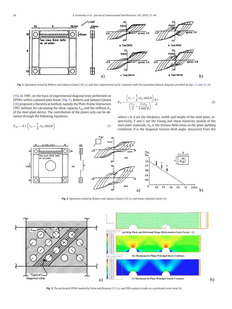
Fig. 1. Specimens tested by Roberts and Sabouri-Ghomi [16] (a) and their experimental cyclic responses with the equivalent bilinear diagrams provided by Eqs. (1) and (2) (b).
38 A. Formisano et al. / Journal of Constructional Steel Research 126 (2016) 37–49
[15]. In 1991, on the basis of experimental diagonal tests performed onSPSWswithin a pinned joint frame (Fig. 1), Roberts and Sabouri-Ghomi[16] proposed a theoreticalmethod, namely the Plate-Frame Interaction(PFI) method, for calculating the shear capacity Fwu and the stiffness Kw
of the steel plate device. The contribution of the plates only can be ob-tained through the following equations:
Fwu ¼ b t τcr þ 12σ ty sin2ϑ
� �ð1Þ
Fig. 2. Specimens tested by Roberts and Sabouri-G
Fig. 3. The perforated SPSW studied by Purba and Bruneau [11]
Kw ¼τcr þ 1
2σ ty sin2ϑ
� �
τcrG
þ 2 σ ty
E sin2ϑ
� � b td
ð2Þ
where t, b, d are the thickness, width and height of the steel plate, re-spectively, E and G are the Young and shear elasticity moduli of thesteel plate materials, σty is the tension-field stress in the plate yieldingcondition, ϑ is the diagonal tension-field angle, measured from the
homi [18] (a) and linear reduction factor (b).
(a) and FEM analysis results on a perforated semi-strip (b).
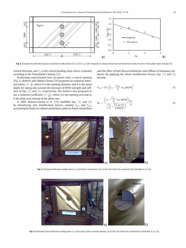
Fig. 4. Example of perforation layouts examined by Bhowmick et al. [20,21] (a) and comparison among theoretical and numerical results in terms of the plate shear strength (b).
39A. Formisano et al. / Journal of Constructional Steel Research 126 (2016) 37–49
vertical direction, and τcr is the critical buckling shear stress, evaluatedaccording to the Timoshenko's theory [17].
Performing experimental tests on panels with a central opening(Fig. 2), Roberts and Sabouri-Ghomi [18] proposed an empirical reduc-tion factor ð1− D
dÞ, where D is the opening diameter and d is the paneldepth, for taking into account the decrease of SPSW strength and stiff-ness in Eqs. (1) and (2), respectively. The Authors also proposed touse a reduction coefficient ð1− A
A0Þ, where A is the opening area and A0
is the plate area, instead of the above one.In 2005 Sabouri-Ghomi et al. [19] modified Eqs. (1) and (2)
by introducing two modification factors, namely Cm1 and Cm2,accounting for beam-to-columnconnections, plate-to-frame connections
Fig. 5. Full panel deformed configuration (a) and failure mechanism
Fig. 6. Perforated panel deformed configuration (a) and tearing failure aroun
and the effect of both flexural behaviour and stiffness of boundary ele-ments. By applying the above modification factors, Eqs. (1) and (2)became:
Fwu ¼ b t τcr þ Cm1
2σ ty sin2ϑ
� �ð3Þ
Kw ¼τcr þ Cm1
2σ ty sin2ϑ
� �
τcrG
þ 2 Cm2 σ ty
E sin2ϑ
� � b td
ð4Þ
s (b) at the end of the test conducted by Valizadeh et al. [22].
d opening (b) at the end of the test conducted by Valizadeh et al. [22].
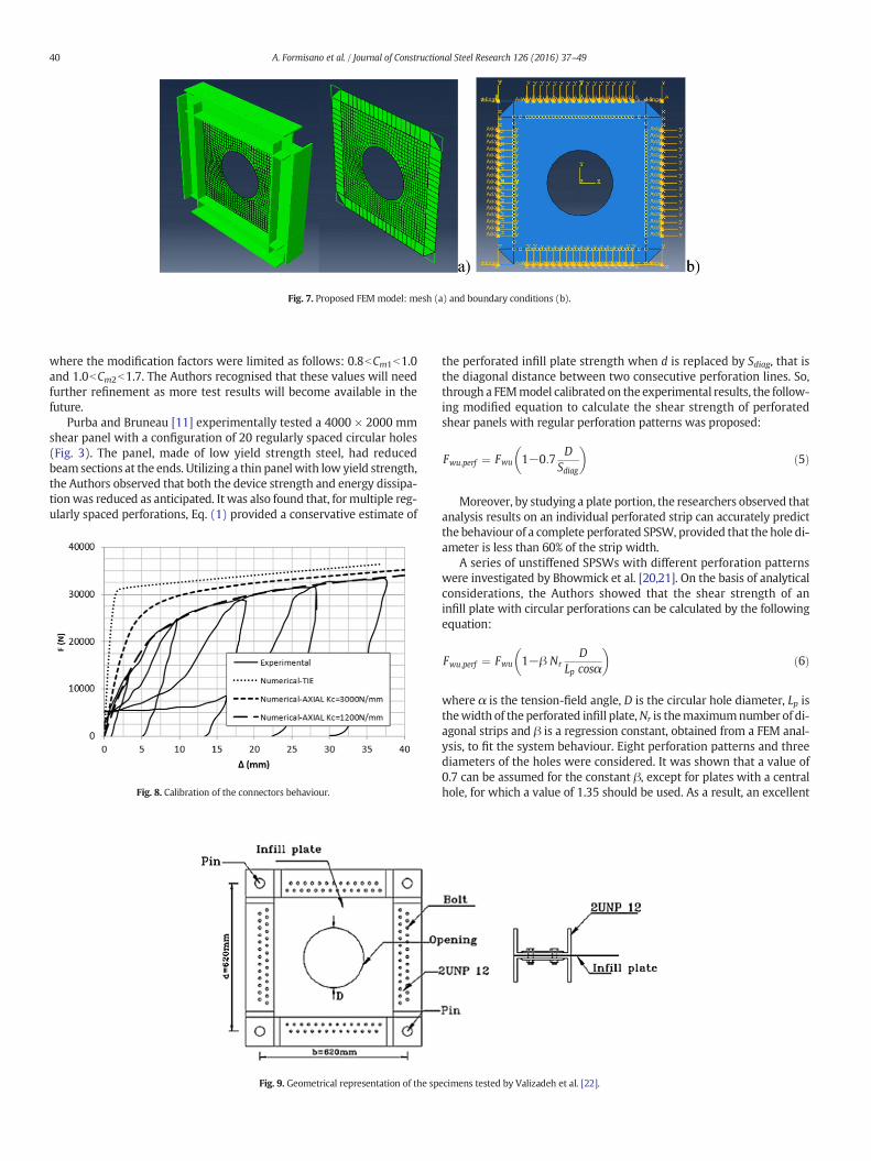
Fig. 7. Proposed FEM model: mesh (a) and boundary conditions (b).
40 A. Formisano et al. / Journal of Constructional Steel Research 126 (2016) 37–49
where the modification factors were limited as follows: 0.8bCm1b1.0and 1.0bCm2b1.7. The Authors recognised that these values will needfurther refinement as more test results will become available in thefuture.
Purba and Bruneau [11] experimentally tested a 4000 × 2000 mmshear panel with a configuration of 20 regularly spaced circular holes(Fig. 3). The panel, made of low yield strength steel, had reducedbeam sections at the ends. Utilizing a thin panel with low yield strength,the Authors observed that both the device strength and energy dissipa-tionwas reduced as anticipated. It was also found that, for multiple reg-ularly spaced perforations, Eq. (1) provided a conservative estimate of
Fig. 8. Calibration of the connectors behaviour.
Fig. 9. Geometrical representation of the sp
the perforated infill plate strength when d is replaced by Sdiag, that isthe diagonal distance between two consecutive perforation lines. So,through a FEMmodel calibrated on the experimental results, the follow-ing modified equation to calculate the shear strength of perforatedshear panels with regular perforation patterns was proposed:
Fwu;perf ¼ Fwu 1−0:7D
Sdiag
� �ð5Þ
Moreover, by studying a plate portion, the researchers observed thatanalysis results on an individual perforated strip can accurately predictthe behaviour of a complete perforated SPSW, provided that the hole di-ameter is less than 60% of the strip width.
A series of unstiffened SPSWs with different perforation patternswere investigated by Bhowmick et al. [20,21]. On the basis of analyticalconsiderations, the Authors showed that the shear strength of aninfill plate with circular perforations can be calculated by the followingequation:
Fwu;perf ¼ Fwu 1−β NrD
Lp cosα
� �ð6Þ
where α is the tension-field angle, D is the circular hole diameter, Lp isthewidth of the perforated infill plate,Nr is themaximumnumber of di-agonal strips and β is a regression constant, obtained from a FEM anal-ysis, to fit the system behaviour. Eight perforation patterns and threediameters of the holes were considered. It was shown that a value of0.7 can be assumed for the constant β, except for plates with a centralhole, for which a value of 1.35 should be used. As a result, an excellent
ecimens tested by Valizadeh et al. [22].
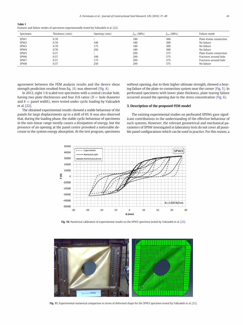
Table 1Features and failure modes of specimens experimentally tested by Valizadeh et al. [22].
Specimen Thickness (mm) Opening (mm) fym (MPa) fum (MPa) Failure mode
SPW1 0.70 / 180 300 Plate-frame connectionSPW2 0.70 100 180 300 No failureSPW3 0.70 175 180 300 No failureSPW4 0.70 250 180 300 No failureSPW5 0.37 / 299 375 Plate-frame connectionSPW6 0.37 100 299 375 Fractures around holeSPW7 0.37 175 299 375 Fractures around holeSPW8 0.37 250 299 375 No failure
41A. Formisano et al. / Journal of Constructional Steel Research 126 (2016) 37–49
agreement between the FEM analysis results and the device shearstrength prediction resulted from Eq. (6) was observed (Fig. 4).
In 2012, eight 1:6 scaled test specimens with a central circular hole,having two plate thicknesses and four D/b ratios (D = hole diameterand b = panel width), were tested under cyclic loading by Valizadehet al. [22].
The obtained experimental results showed a stable behaviour of thepanels for large displacements up to a drift of 6%. It was also observedthat, during the loading phase, the stable cyclic behaviour of specimensin the non-linear range mostly causes a dissipation of energy, but thepresence of an opening at the panel centre provoked a noticeable de-crease in the system energy absorption. At the test program, specimens
Fig. 10. Numerical calibration of experimental results on
Fig. 11. Experimental-numerical comparison in terms of deformed
without opening, due to their higher ultimate strength, showed a bear-ing failure of the plate-to-connection system near the corner (Fig. 5). Inperforated specimens with lower plate thickness, plate tearing failureoccurred around the opening due to the stress concentration (Fig. 6).
3. Description of the proposed FEM model
The existing experimental studies on perforated SPSWs gave signif-icant contributions to the understanding of the effective behaviour ofsuch systems. However, the relevant geometrical and mechanical pa-rameters of SPSW investigated in laboratory tests do not cover all possi-ble panel configurationswhich can be used in practice. For this reason, a
the SPW3 specimen tested by Valizadeh et al. [22].
shape for the SPW3 specimen tested by Valizadeh et al. [22].
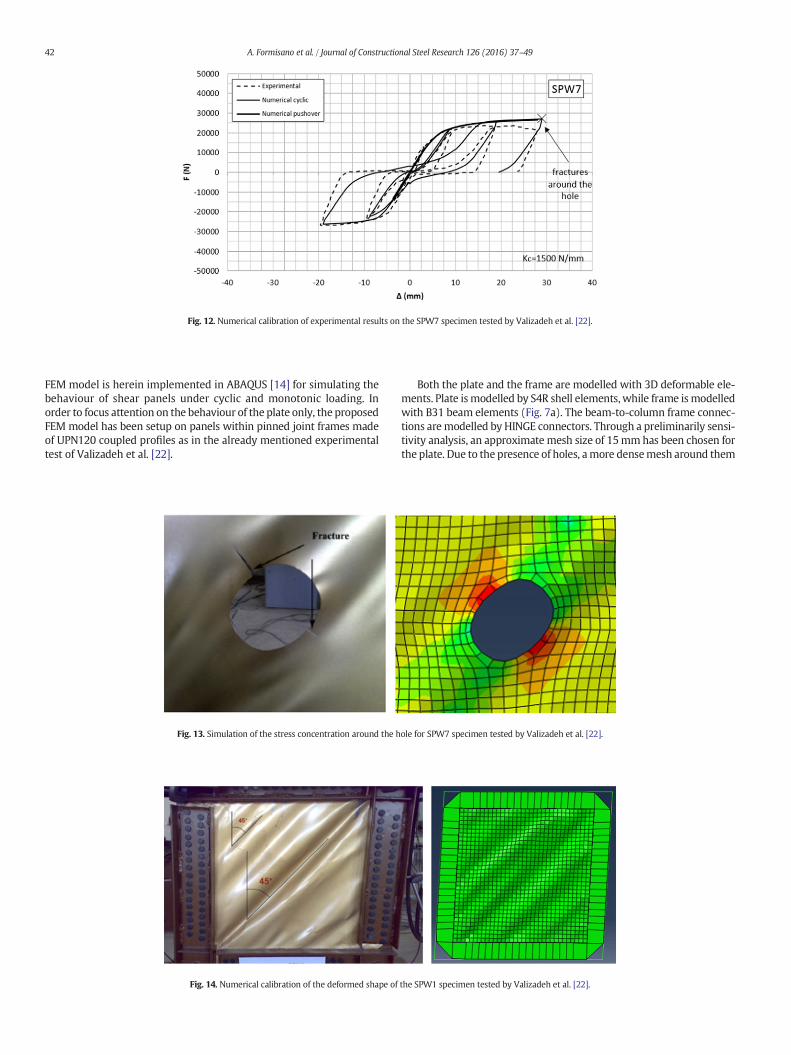
Fig. 12. Numerical calibration of experimental results on the SPW7 specimen tested by Valizadeh et al. [22].
42 A. Formisano et al. / Journal of Constructional Steel Research 126 (2016) 37–49
FEM model is herein implemented in ABAQUS [14] for simulating thebehaviour of shear panels under cyclic and monotonic loading. Inorder to focus attention on the behaviour of the plate only, the proposedFEM model has been setup on panels within pinned joint frames madeof UPN120 coupled profiles as in the already mentioned experimentaltest of Valizadeh et al. [22].
Fig. 13. Simulation of the stress concentration around the h
Fig. 14. Numerical calibration of the deformed shape of
Both the plate and the frame are modelled with 3D deformable ele-ments. Plate ismodelled by S4R shell elements, while frame ismodelledwith B31 beam elements (Fig. 7a). The beam-to-column frame connec-tions aremodelled by HINGE connectors. Through a preliminarily sensi-tivity analysis, an approximate mesh size of 15mmhas been chosen forthe plate. Due to the presence of holes, amore densemesh around them
ole for SPW7 specimen tested by Valizadeh et al. [22].
the SPW1 specimen tested by Valizadeh et al. [22].
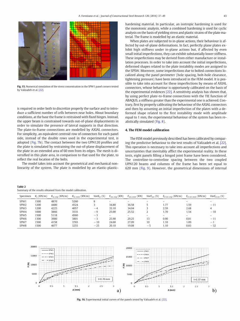
Fig. 15.Numerical simulation of the stress concentration in the SPW1panel corners testedby Valizadeh et al. [22].
43A. Formisano et al. / Journal of Constructional Steel Research 126 (2016) 37–49
is required in order both to discretize properly the surface and to intro-duce a sufficient number of cells between near holes. About boundaryconditions, at the base the frame is restrainedwithfixed hinges. Instead,the upper beam is constrained towards out-of-plane displacements inorder to simulate the presence of lateral supports in that direction.The plate-to-frame connections are modelled by AXIAL connectors.For simplicity, an equivalent centroid row of connectors for each panelside, instead of the double rows used in the experimental test, isadopted (Fig. 7b). The contact between the two UPN120 profiles andthe plate is simulated by restraining the out-of-plane displacement ofthe plate in an extended area of 60 mm from its edges. The mesh is di-versified in this plate area, in comparison to that used for the plate, toreflect the real location of the bolts.
The model takes into account the geometrical and mechanical non-linearity of the system. The plate is modelled by an elastic-plastic-
Table 2Summary of the results obtained from the model calibration.
Specimen Kc (KN/m) Kw ,exp (KN/m) Kw ,num (KN/m) VarKw (%) Fwu ,exp (KN)
SPW1 1500 4870 5260 8 –SPW2 1200 4400 4524 3 34.80SPW3 1200 4225 4057 −4 33.10SPW4 1000 3866 3535 −9 25.00SPW5 1500 5118 4960 −3 –SPW6 1300 3900 3801 −3 25.90SPW7 1500 4158 3765 −10 24.60SPW8 1500 4077 3255 −25 20.10
Fig. 16. Experimental initial curves of the
hardening material. In particular, an isotropic hardening is used forthe monotonic analysis, while a combined hardening is used for cyclicanalysis on the basis of yielding stress andplastic strains of theplatema-terial. The frame is modelled by an elastic material.
When plates are subjected to in-plane actions, their behaviour is af-fected by out-of-plane deformations. In fact, perfectly plane plates ex-hibit high stiffness under in-plane actions but, if affected by evensmall initial imperfections, they can exhibit substantially lower stiffness.These imperfections may be derived from either manufacture or instal-lation processes. In order to take into account the initial imperfections,deformed shapes related to the plate instability modes are assigned tothe SPSW. Moreover, some imperfections due to bolted connections lo-calized along the panel perimeter (hole spacing, bolt-hole clearance,tightening pressure) have been introduced in the FEMmodel. It is pos-sible to take into account for these imperfections by means of AXIALconnectors, whose behaviour is opportunely calibrated on the basis ofthe experimental evidences [22]. A sensitivity analysis has shown that,by using perfect plate-to-frame connections with the TIE function ofABAQUS, a stiffness greater than the experimental one is achieved. Con-trary,first by properly calibrating the behaviour of theAXIAL connectorsand then by assuming an initial imperfection of the plates with a de-formed shape related to the first instability mode with amplitudeequal to 1 mm, the experimental behaviour of the system has been re-alistically simulated (Fig. 8).
4. The FEMmodel calibration
The FEMmodel previously described has been calibrated by compar-ing the predictive behaviour to the test results of Valizadeh et al. [22].This operation is necessary to take into account all imperfections anduncertainties that inevitably afflict the experimental reality. In thesetests, eight panels filling a hinged joint frame have been considered.The centreline-to-centreline spacing between the two coupledUPN120 beams and columns of the frame has been set equal to620 mm (Fig. 9). However, the geometrical dimensions of internal
Fwu ,num (KN) VarFwu (%) Ed ,tot ,exp (KN/m) Ed ,tot ,num (KN/m) VarEd ,tot (%)
– – – – –36.58 5 1.77 1.59 −1134.04 3 2.59 2.68 425.52 2 1.70 1.54 −10– – – – –29.25 13 0.90 0.81 −1127.09 10 1.10 1.09 −119.08 −5 1.10 0.83 −32
panels tested by Valizadeh et al. [22].
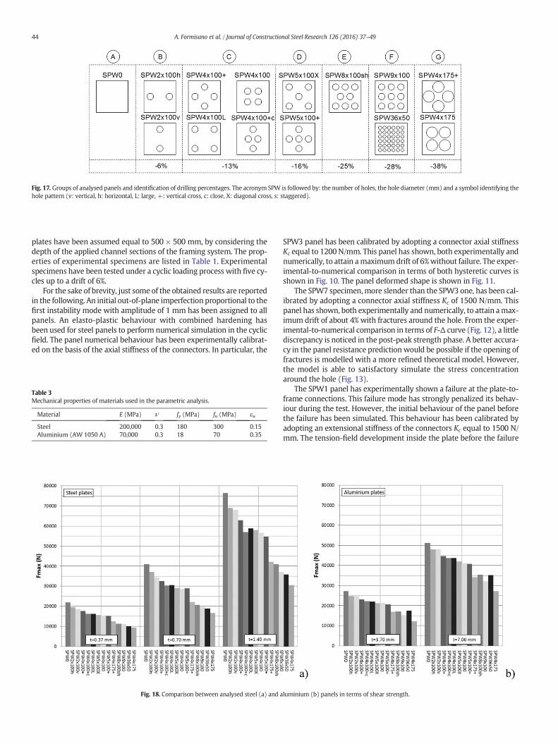
Fig. 17. Groups of analysed panels and identification of drilling percentages. The acronym SPW is followed by: the number of holes, the hole diameter (mm) and a symbol identifying thehole pattern (v: vertical, h: horizontal, L: large, +: vertical cross, c: close, X: diagonal cross, s: staggered).
44 A. Formisano et al. / Journal of Constructional Steel Research 126 (2016) 37–49
plates have been assumed equal to 500 × 500 mm, by considering thedepth of the applied channel sections of the framing system. The prop-erties of experimental specimens are listed in Table 1. Experimentalspecimens have been tested under a cyclic loading process with five cy-cles up to a drift of 6%.
For the sake of brevity, just some of the obtained results are reportedin the following. An initial out-of-plane imperfection proportional to thefirst instability mode with amplitude of 1 mm has been assigned to allpanels. An elasto-plastic behaviour with combined hardening hasbeen used for steel panels to perform numerical simulation in the cyclicfield. The panel numerical behaviour has been experimentally calibrat-ed on the basis of the axial stiffness of the connectors. In particular, the
Table 3Mechanical properties of materials used in the parametric analysis.
Material E (MPa) ν fy (MPa) fu (MPa) εu
Steel 200,000 0.3 180 300 0.15Aluminium (AW 1050 A) 70,000 0.3 18 70 0.35
Fig. 18. Comparison between analysed steel (a) and a
SPW3 panel has been calibrated by adopting a connector axial stiffnessKc equal to 1200 N/mm. This panel has shown, both experimentally andnumerically, to attain amaximumdrift of 6%without failure. The exper-imental-to-numerical comparison in terms of both hysteretic curves isshown in Fig. 10. The panel deformed shape is shown in Fig. 11.
The SPW7 specimen,more slender than the SPW3 one, has been cal-ibrated by adopting a connector axial stiffness Kc of 1500 N/mm. Thispanel has shown, both experimentally and numerically, to attain amax-imum drift of about 4% with fractures around the hole. From the exper-imental-to-numerical comparison in terms of F-Δ curve (Fig. 12), a littlediscrepancy is noticed in the post-peak strength phase. A better accura-cy in the panel resistance prediction would be possible if the opening offractures is modelled with a more refined theoretical model. However,the model is able to satisfactory simulate the stress concentrationaround the hole (Fig. 13).
The SPW1 panel has experimentally shown a failure at the plate-to-frame connections. This failure mode has strongly penalized its behav-iour during the test. However, the initial behaviour of the panel beforethe failure has been simulated. This behaviour has been calibrated byadopting an extensional stiffness of the connectors Kc equal to 1500 N/mm. The tension-field development inside the plate before the failure
luminium (b) panels in terms of shear strength.
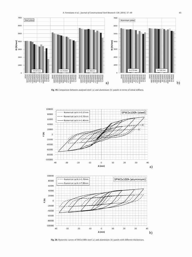
Fig. 19. Comparison between analysed steel (a) and aluminium (b) panels in terms of initial stiffness.
Fig. 20. Hysteretic curves of SW2x100h steel (a) and aluminium (b) panels with different thicknesses.
45A. Formisano et al. / Journal of Constructional Steel Research 126 (2016) 37–49
46 A. Formisano et al. / Journal of Constructional Steel Research 126 (2016) 37–49
is shown in Fig. 14. Moreover, the FEM model is able to simulate thestress concentration in the panel corners (Fig. 15).
The final results of the calibration phase in terms of initial stiffness(Kw), shear strength (Fwu) and total energy dissipated during the testingprocess (Ed ,tot) have been listed in Table 2. Since the experimental testresults on the more slender panels have shown a dependence fromboth the initial buckling for low load levels and the initial slipping (i.e.SPW6 and SPW7 panels), a secant stiffness at a displacement of 3 mmhas been conventionally assumed for a more realistic representationof the initial experimental behaviour of the panels. With these assump-tions, the results have shown that the FEMmodel is able to satisfactorysimulate the behaviour of shear panels in terms of stiffness, with the ex-ception of SPW8 panel, which has experimentally shown a larger stiff-ness than that of the other panels with the same thickness, despite thepresence of the greatest hole diameter (see Fig. 16b). The comparisonbetween experimental and numerical results in terms of strength forSPW6 and SPW7 panels has shown a greater difference due to the lackof modelling of the fracture observed around the holes during the ex-perimental tests (see Fig. 12). Less accuracy has been also observed insimulating the pinching effect, due to local instabilities occurrence.However, except for the SPW8 panel, the FEMmodel can be consideredas sufficiently reliable, as it accurately estimates the three basic param-eters (Kw, Fwu, Ed ,tot) characterizing the physical behaviour of the panelscoming from the experimental evidence.
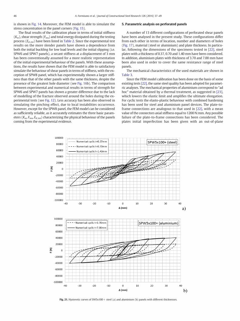
Fig. 21. Hysteretic curves of SW5x100+ steel (a) and
5. Parametric analysis on perforated panels
A number of 13 different configurations of perforated shear panelshave been analysed in the present study. These configurations differfrom each other in terms of location, number and diameters of holes(Fig. 17), material (steel or aluminium) and plate thickness. In particu-lar, following the dimensions of the specimens tested in [22], steelplates with a thickness of 0.37, 0.70 and 1.40mmhave been considered.In addition, aluminium plates with thickness of 3.70 and 7.00 mm havebeen also used in order to cover the same resistance range of steelpanels.
The mechanical characteristics of the used materials are shown inTable 3.
Since the FEMmodel calibration has been done on the basis of someexisting tests [22], the same steel quality has been adopted for paramet-ric analyses. Themechanical properties of aluminium correspond to “adhoc” material obtained by a thermal treatment, as suggested in [23],which lowers the elastic limit and amplifies the ultimate elongation.For cyclic tests the elasto-plastic behaviour with combined hardeninghas been used for steel and aluminium panel devices. The plate-to-frame connections are analogous to that used in [22], with a meanvalue of the connectors axial stiffness equal to 1200N/mm. Anypossiblefailure of the plate-to-frame connections has been considered. Theplates initial imperfection has been given with an out-of-plane
aluminium (b) panels with different thicknesses.
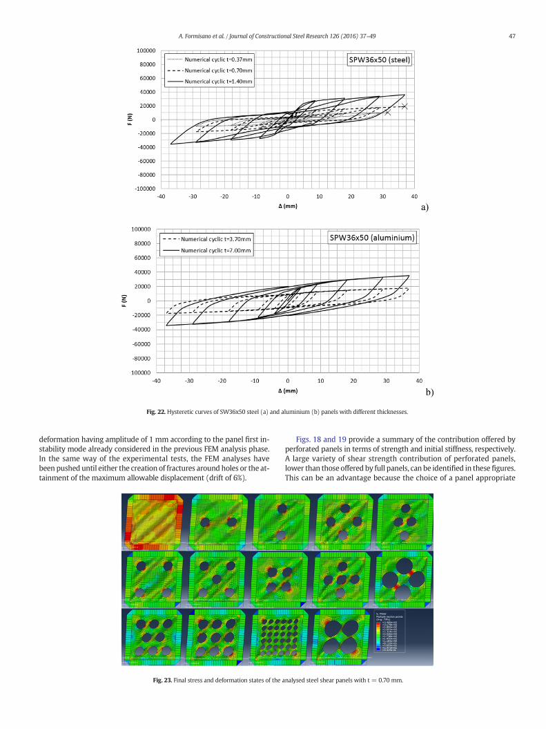
Fig. 22. Hysteretic curves of SW36x50 steel (a) and aluminium (b) panels with different thicknesses.
47A. Formisano et al. / Journal of Constructional Steel Research 126 (2016) 37–49
deformation having amplitude of 1 mm according to the panel first in-stability mode already considered in the previous FEM analysis phase.In the same way of the experimental tests, the FEM analyses havebeen pushed until either the creation of fractures around holes or the at-tainment of the maximum allowable displacement (drift of 6%).
Fig. 23. Final stress and deformation states of the a
Figs. 18 and 19 provide a summary of the contribution offered byperforated panels in terms of strength and initial stiffness, respectively.A large variety of shear strength contribution of perforated panels,lower than those offered by full panels, can be identified in these figures.This can be an advantage because the choice of a panel appropriate
nalysed steel shear panels with t = 0.70 mm.
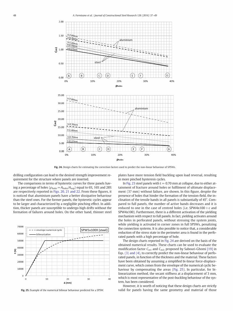
Fig. 24. Design charts for estimating the correction factors used to predict the non-linear behaviour of SPSWs.
48 A. Formisano et al. / Journal of Constructional Steel Research 126 (2016) 37–49
drilling configuration can lead to the desired strength improvement re-quirement for the structure where panels are inserted.
The comparisons in terms of hysteretic curves for three panels hav-ing a percentage of holes (ρholes=Aholes/Asup) equal to 6%, 16% and 28%are respectively reported in Figs. 20, 21 and 22. From these figures, itis noticed that aluminium panels have a better dissipative behaviourthan the steel ones. For the former panels, the hysteretic cycles appearto be larger and characterized by a negligible pinching effect. In addi-tion, thicker panels are susceptible to undergo high drifts without theformation of failures around holes. On the other hand, thinner steel
Fig. 25. Example of the numerical bilinear behaviour predicted for a SPSW.
plates have more tension field buckling upon load reversal, resultingin more pinched hysteresis cycles.
In Fig. 23 steel panels with t= 0.70mmat collapse, due to either at-tainment of fracture around holes or fulfilment of ultimate displace-ment (37 mm) without failure, are shown. In this figure, despite thepresence of holes that hinder the formation of the tension-field, the in-clination of the tensile bands in all panels is substantially of 45°. Com-pared to full panels, the number of active bands decreases and it isreduced to one in the case of centred holes (i.e. SPW4x100+c andSPW4x100). Furthermore, there is a different activation of the yieldingmechanismwith respect to full panels. In fact, yielding activates aroundthe holes in perforated panels, without stressing the system joints,while yielding is activated in corner zones in full SPSWs, penalizingthe connection systems. It is also possible to notice that, a considerablereduction of the stress state in the perimeter area is found in the perfo-rated panels with a high percentage of hole.
The design charts reported in Fig. 24 are derived on the basis of theobtained numerical results. These charts can be used to evaluate themodification factor Cm1 and Cm2, proposed by Sabouri-Ghomi [19] inEqs. (3) and (4), to correctly predict the non-linear behaviour of perfo-rated panels, in function of the thickness and thematerial. These factorshave been obtained by assuming a simplified bi-linear force-displace-ment curve, which comes from the envelope of the numerical cyclic be-haviour by compensating the areas (Fig. 25). In particular, for bi-linearization method, the secant stiffness at a displacement of 3 mm,which is most representative of the post-buckling behaviour of the sys-tem, has been considered.
However, it is worth of noticing that these design charts are strictlyvalid for panels having the same geometry and material of those
49A. Formisano et al. / Journal of Constructional Steel Research 126 (2016) 37–49
considered in the parametric analysis. Therefore, additional studiesshould be developed to extend the achieved results to other cases.
Fig. 24 shows that the values of Cm1 and Cm2 assigned to aluminiumpanels are always higher than those used for steel ones. This trend canbe explained as follows: the increasing of Cm1, which affects the strength(Eq. (3)), is due to the higher value of strain-hardening for aluminium;the increasing of Cm2, which affects the initial stiffness (Eq. (4)), de-pends on the lower value of the Young's modulus of aluminium respectto the steel one, being Cm2 at the denominator in the formula.
6. Conclusions
The results of a wide FEM study on unstiffened perforated shearpanels are presented in this paper. This paper represents a detailed ex-tension of the contents already presented in [24]. The available experi-mental results on panels with a central opening have allowed to setupand calibrate an appropriate FEM model, where geometric imperfec-tions and material non-linearity have been considered. The presenceof the bolted plate-to-frame connections and their imperfections havebeen also simply taken into account in this model. The proper calibra-tion of the FEM model has guaranteed to obtain a satisfactory numeri-cal-to-experimental agreement in terms of both the overall behaviourand the consequential deformed shape of the system.
On this consolidated basis, a parametric FEM analysis on panels withdifferent perforation patterns, material and thickness has been carried-out. The different perforation patterns have been considered bymodify-ing location, number and diameter of the holes. Two types of materialhave been assumed: steel and aluminium. From the results it is ob-served that, despite the presence of holes, the inclination of tension-field essentially remains about 45°. The number of active bands de-creases in comparison to the one full panels and it depends on theholes location, as also declared in [11]. Furthermore, the activationmode of the yielding mechanism is favourable for perforated panels,as it occurs in the areas around the holes instead of the perimeterzones like in full panels, which penalize the connection systems. A con-siderable reduction of the stresses in the perimeter area is found in per-forated panels with a high percentage of holes. In addition, by adoptingthicker perforated plates, very large drifts can be attained without fail-ure around holes. In conclusion, the aluminium panels showed a moredissipative behaviour than steel panel ones, with the hysteretic curvesafflicted by a negligible pinching effect.
Finally, it is shown that the use of conventional steel panelswith dif-ferent perforation patterns can be a viable alternative to full panels forstrengthening and stiffening both new and existing structures. In fact,if perforated panels are applied for example to an existing structure,by choosing an appropriate drilling configuration, the resistance of theoriginal building can be improved without overloading the main struc-ture with high stresses deriving from the tension-field generated in theplates. Furthermore, due toweakening effect induced by theholes in theplates, perforated panels, other beingmore economic than full ones, re-quire, when applied into existing buildings, less local reinforcement in-terventions to structural members in comparison to those imposed byfull panels.
References
[1] A. Astaneh-Asl, Seismic behaviour and design of steel shear walls, Steel Technical In-formation and Product Services Report, Structural Steel Educational Council,Moraga, CA, 2000.
[2] G. De Matteis, A. Formisano, F.M. Mazzolani, S. Panico, Design of low-yield metalshear panels for energy dissipation, Proc. of the Final Conference of COST ACTIONC12, Innsbruck, Austria January 20–22 2005, pp. 665–675.
[3] A. Formisano, F.M. Mazzolani, G. Brando, G. De Matteis, Numerical evaluation of thehysteretic performance of pure aluminium shear panels, Proc. of the 5th Int. Confer-ence on the Behaviour of Steel Structures in Seismic Areas (STESSA ‘06), Yokohama,Japan, Taylor & Francis Group plc, London, UK August 14–17 2006, pp. 211–217.
[4] K. Basler, Strength of plate girders in shear, J. Struct. Div. ASCE 87 (7) (1961)150–180.
[5] A. Formisano, F.M. Mazzolani, G. De Matteis, Numerical analysis of slender steelshear panels for assessing design formulas, Int. J. Struct. Stab. Dyn. 7 (2007)273–294.
[6] M. Xue, L.W. Lu, Interaction of infilled steel shear wall panels with surroundingframe members, Proc. Annual Task Group Technical Session, Structural Stability Re-search Council: Reports on Current Research Activities, Lehigh University, Bethle-hem, PA June 20, 1994, pp. 339–354.
[7] T. Hitaka, C. Matsui, Experimental study on steel shear wall with slits, J. Struct. Eng.129 (5) (2003) 586–595.
[8] J.W. Berman,M. Bruneau, Experimental investigation of light-gauge steel plate shearwalls, J. Struct. Eng. 131 (2) (2005) 259–267.
[9] D. Vian, M. Bruneau, Steel plate shear walls for seismic design and retrofit of build-ing structures, Technical Rep. No. MCEER-05-0010, Multidisciplinary Center forEarthquake Engineering Research, State Univ. of New York, Buffalo, N.Y., 2005
[10] E.S. Mistakidis, G. DeMatteis, A. Formisano, Low yieldmetal shear panels as an alter-native for the seismic upgrading of concrete structures, Adv. Eng. Softw. 38 (2007)626–636.
[11] R. Purba, M. Bruneau, Design recommendations for perforated steel plate shearwalls, Technical Rep. No. MCEER-07-0011, Multidisciplinary Center for EarthquakeEngineering Research, State Univ. of New York, Buffalo, N.Y., 2007
[12] A. Formisano, G. DeMatteis, F.M. Mazzolani, Numerical and experimental behaviourof a full-scale RC structure upgraded with steel and aluminium shear panels,Comput. Struct. 88 (2010) 1348–1360.
[13] G. De Matteis, A. Formisano, F.M. Mazzolani, An innovativemethodology for seismicretrofitting of existing RC buildings by metal shear panels, Earthq. Eng. Struct. Dyn.38 (2009) 61–78.
[14] Hibbitt, Karlsson, and Sorenson, ABAQUS/CAE User's Manual, Version 6.10, HKS Inc.,Pawtucket, RI, 2010.
[15] L.J. Thorburn, G.L. Kulak, C.J. Montgomery, Analysis of steel plate shear walls, Struct.Eng. Rep. No. 107, Dept. of Civ. Eng., University of Alberta, Edmonton, Alta., Canada,1983.
[16] T.M. Roberts, S. Sabouri-Ghomi, Hysteretic characteristics of unstiffened steel plateshear panels, Thin-Walled Struct. 14 (1991) 145–162.
[17] S.P. Timoshenko, J.M. Gere, Theory of Elastic Stability, McGraw-Hill Book Company,1961.
[18] T.M. Roberts, S. Sabouri-Ghomi, Hysteretic characteristics of unstiffened perforatedsteel plate shear panels, Thin-Walled Struct. 14 (1992) 139–151.
[19] S. Sabouri-Ghomi, C.E. Ventura, M.H.K. Kharrazi, Shear analysis and design of ductilesteel plate walls, J. Struct. Eng. 131 (2005) 878–889.
[20] A.K. Bhowmick, Seismic behaviour of steel plate shear walls with centrally placedcircular perforations, Thin-Walled Struct. 75 (2014) 30–42.
[21] A.K. Bhowmick, G.Y. Grondin, R.G. Driver, Nonlinear seismic analysis of perforatedsteel plate shear walls, J. Constr. Steel Res. 94 (2014) 103–113.
[22] H. Valizadeh, M. Sheidaii, H. Showkati, Experimental investigation on cyclic behav-iour of perforated steel plate shear walls, J. Constr. Steel Res. 70 (2012) 308–316.
[23] G. De Matteis, A. Formisano, F.M. Mazzolani, S. Panico, Numerical and experimentalanalysis of pure aluminium shear panels with welded stiffeners, Comput. Struct. 30(2008) 545–555.
[24] A. Formisano, L. Lombardi, F.M. Mazzolani, On the use of perforated metal shearpanels for seismic-resistant application, 8th International Conference on Behaviorof Steel Structures in Seismic Areas, Shanghai, China, July 1–3 2015.