j1708 – j1587 protocol multiple ecu description … features j1708 – j1587 protocol multiple ecu...
TRANSCRIPT
1
Features
J1708 – J1587Protocol Multiple ECU Simulator
● Simulates up to 4 DTC’s at a time➢ 3 DTC’s are triggered when values exceed certain thresholds➢ 1 DTC is available on button press
● Strongly compliant to the J1587 standard➢ DTC’s interact with each other as defined by the standard
● Implemented Transfer Protocol➢ Segmented messages and handshaking sequences can be
simulated
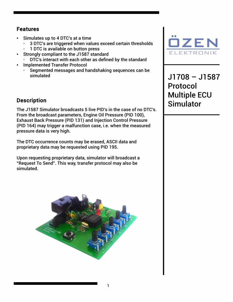
Description
The J1587 Simulator broadcasts 5 live PID’s in the case of no DTC’s. From the broadcast parameters, Engine Oil Pressure (PID 100), Exhaust Back Pressure (PID 131) and Injection Control Pressure (PID 164) may trigger a malfunction case, i.e. when the measured pressure data is very high.
The DTC occurrence counts may be erased, ASCII data and proprietary data may be requested using PID 195.
Upon requesting proprietary data, simulator will broadcast a “Request To Send”. This way, transfer protocol may also be simulated.
2
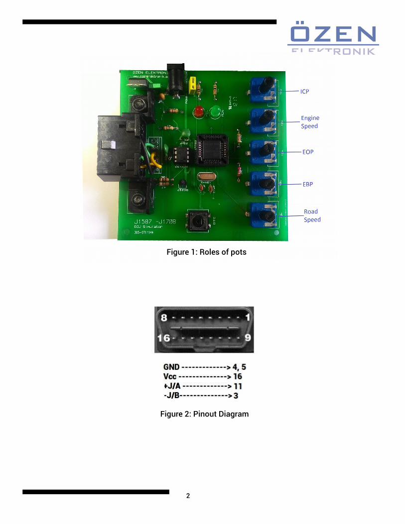
Figure 1: Roles of pots
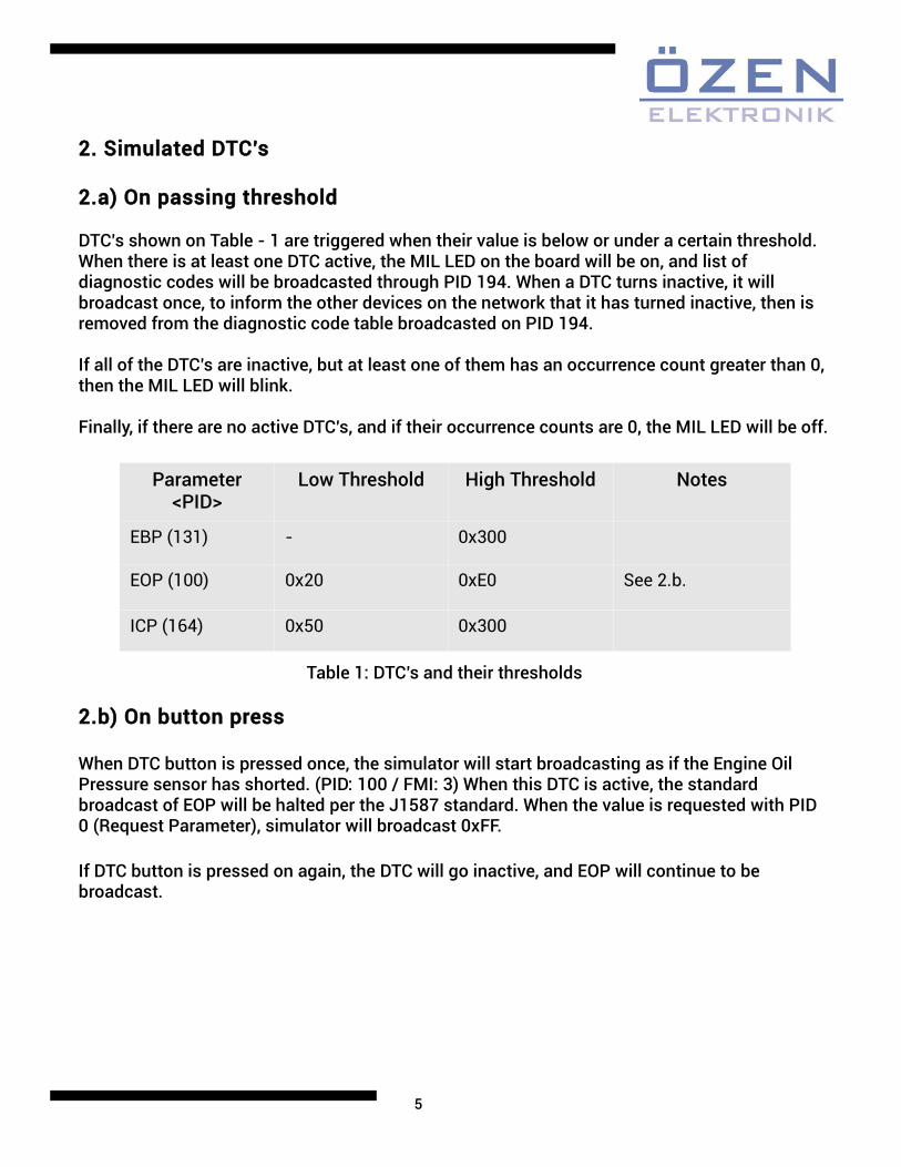
Figure 2: Pinout Diagram

3
1. Simulated Parameters
1.1) Road Speed— Indicated vehicle velocity. (MID: 144 / PID: 84)
Parameter Data Length: 1 CharacterData Type: Unsigned Short IntegerBit Resolution: 0.805 km/h (0.5 mph)Maximum Range: 0.0 to 205.2 km/h (0.0 to 127.5 mph)Transmission Update Period: 0.1 sMessage Priority: 1Format:PID Data84 aa— Road speed
1.2) Exhaust Back Pressure— Gage pressure of exhaust gas measured at the exhaust manifold. (MID: 128 / PID: 131)
Parameter Data Length: 2 CharactersData Type: Unsigned IntegerBit Resolution: 6.733 x 10 –3 kPa (1/1024 lbf/in 2 )Maximum Range: 0.0 to 441.258 kPa (0.0 to 63.999 lbf/in 2 )Transmission Update Period: 1 sMessage Priority: 4Format:PID Data131 a aa a— Exhaust back pressure
1.3) Engine Oil Pressure— Gage pressure of oil in engine lubrication system as provided by oil pump. (MID: 128 / PID: 100)
Parameter Data Length: 1 CharacterData Type: Unsigned Short IntegerBit Resolution: 3.45 kPa (0.5 lbf/in 2 )Maximum Range: 0.0 to 879.0 kPa (0.0 to 127.5 lbf/in 2 )Transmission Update Period: 1.0 sMessage Priority: 2Format:PID Data100 aa— Engine oil pressure
4
1.4) Engine Speed— Rotational velocity of crankshaft. (MID: 128 / PID: 190)
Parameter Data Length: 2 CharactersData Type: Unsigned IntegerBit Resolution: 0.25 rpmMaximum Range: 0.0 to 16383.75 rpmTransmission Update Period: 0.1 sMessage Priority: 1Format:PID Data190 a aa a— Engine speed
1.5) Injection Control Pressure— The gage pressure of the hydraulic accumulator that powers fuel injection. (MID: 128 / PID: 164)
Parameter Data Length: 2 CharactersData Type: Unsigned IntegerBit Resolution: 1/256 MPaMaximum Range: 0 to 255.996 MPaTransmission Update Period: 1.0 sMessage Priority: 5Format:PID Data164 a aa a— Injection control pressure
1.6) Brake Primary Pressure— Gage pressure of air in the primary, or supply side, of the air brake system. (PID: 117/ MID: 136)
Parameter Data Length: 1 CharacterData Type: Unsigned Short IntegerBit Resolution: 4.14 kPa (0.6 lbf/in 2 )Maximum Range: 0.0 to 1055 kPa (0.0 to 153.0 lbf/in 2 )Transmission Update Period: On request*Message Priority: 1Format:PID Data117 aa— Brake primary pressure
Note: This parameter’s value is fixed to 0xBB.
*Transmission periods marked with asterisks are different from the values recommended by SAE.
5
2. Simulated DTC’s
2.a) On passing threshold
DTC’s shown on Table - 1 are triggered when their value is below or under a certain threshold. When there is at least one DTC active, the MIL LED on the board will be on, and list of diagnostic codes will be broadcasted through PID 194. When a DTC turns inactive, it will broadcast once, to inform the other devices on the network that it has turned inactive, then is removed from the diagnostic code table broadcasted on PID 194.
If all of the DTC’s are inactive, but at least one of them has an occurrence count greater than 0, then the MIL LED will blink.
Finally, if there are no active DTC’s, and if their occurrence counts are 0, the MIL LED will be off.
2.b) On button press
When DTC button is pressed once, the simulator will start broadcasting as if the Engine Oil Pressure sensor has shorted. (PID: 100 / FMI: 3) When this DTC is active, the standard broadcast of EOP will be halted per the J1587 standard. When the value is requested with PID 0 (Request Parameter), simulator will broadcast 0xFF.
If DTC button is pressed on again, the DTC will go inactive, and EOP will continue to be broadcast.
Parameter <PID>
Low Threshold High Threshold Notes
EBP (131) - 0x300
EOP (100) 0x20 0xE0 See 2.b.
ICP (164) 0x50 0x300
Table 1: DTC’s and their thresholds
6
3. Supported Commands
3.a) Request Parameter (PID 0)
All of the parameters listed in Section 1 can be requested. Simulator will respond with the latest measured value of the corresponding parameter.
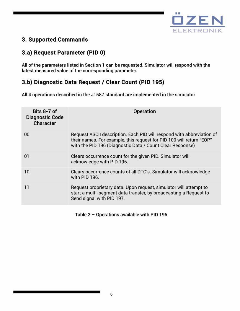
3.b) Diagnostic Data Request / Clear Count (PID 195)
All 4 operations described in the J1587 standard are implemented in the simulator.
Bits 8-7 of Diagnostic Code
Character
Operation
00 Request ASCII description. Each PID will respond with abbreviation of their names. For example, this request for PID 100 will return “EOP” with the PID 196 (Diagnostic Data / Count Clear Response)
01 Clears occurrence count for the given PID. Simulator will acknowledge with PID 196.
10 Clears occurrence counts of all DTC’s. Simulator will acknowledge with PID 196.
11 Request proprietary data. Upon request, simulator will attempt to start a multi-segment data transfer, by broadcasting a Request to Send signal with PID 197.
Table 2 – Operations available with PID 195

7
4. Transport Protocol Simulation
J1587 uses a handshake based transport protocol. It can be simulated by requesting proprietary data from any DTC, as told in Section 3. When done so, simulator will broadcast a Request to Send message, requesting to send 5 segments. Each segment has the string “ThisIsSegment<segment number>”, ending with a null character.
If the request is accepted by the off-board user device, by responding with Clear To Send, simulator will start to broadcast the segments, with the number depending on the data sent with Clear To Send message.
Figure 3: Example application of transport protocol
8
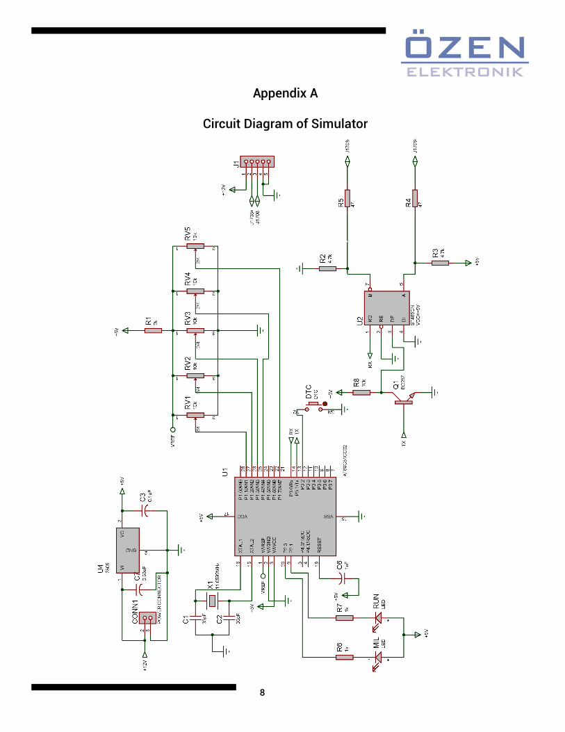
Appendix A
Circuit Diagram of Simulator