iv 1 concept of an innovative passenger-car hybrid drive ... · concept of an innovative...
TRANSCRIPT
Concept of an Innovative Passenger-Car Hybrid Drive
for European Driving Conditions
Kemper, Hans; Hellenbroich, Gereon; Esch, Thomas
FEV Motorentechnik Aachen
Neuenhofstraße 181, 52078 Aachen
Tel: 0241-5689-6713, Fax: 0241-5689-76713, [email protected]
Abstract
The downsizing of spark ignition engines in conjunction with turbocharging is considered to be a promising method for reducing CO2 emissions. Using this concept, FEV has developed a new, highly efficient drivetrain to demonstrate fuel consumption reduction and drivability in a vehicle based on the Ford Focus ST. The newly designed 1.8L turbocharged gasoline engine incorporates infinitely variable intake and outlet control timing and direct fuel injection utilizing piezo injectors centrally located. In addition, this engine uses a prototype FEV engine control system, with software that was developed and adapted entirely by FEV. The vehicle features a 160 kW engine with a maximum mean effective pressure of 22.4 bar and 34% savings in simulated fuel consumption. During the first stage, a new electrohydraulically actuated hybrid transmission with seven forward gears and one reverse gear and a single dry starting clutch will be integrated. The electric motor of the hybrid is directly connected to the gear set of the transmission. Utilizing the special gear set layout, the electric motor can provide boost during a change of gears, so that there is no interruption in traction. Therefore, the transmission system combines the advantages of a double clutch controlled gear change (gear change without an interruption in traction) with the efficient, cost-effective design of an automated manual transmission system. Additionally, the transmission provides a purely electric drive system and the operation of an air-conditioning compressor during the engine stop phases. One other alternative is through the use of CAI (Controlled Auto Ignition), which incorporates a process developed by FEV for controlled compression ignition.
Introduction In contrast to the American and Japanese car market, the European car market is still dominated by the manual transmission. There are several reasons for this. Beside customer preferences and high price premiums for automatic transmissions another vital factor has been the efficiency of manual transmissions, which for a long time had been far better than that of any automatic transmission. The success of the dual clutch transmission (DCT) in Europe is therefore also based on the fact that the additional comfort is not compromised by excessive fuel consumption. Compared to the manual transmission, the inherent disadvantages of the actuation such as higher drag losses and the energy consumption system are partially compensated by a driver-independent, optimized shift strategy and by an increased number of gear ratios and larger total ratio spreads. Although it is expected that the manual transmission can keep its dominant position for the time being, the market share of the DCT will steadily increase as the rising fuel prices and the ongoing CO2-debate pave the way for even more efficient powertrains: Hybrids. The Transmission of the „Europahybrid“ Especially when developing a hybrid powertrain for the European market, the transmission efficiency plays a key role, as the basis of comparison will be the manual transmission because of its high market share. Therefore, AMT (automated manual transmission) technology was chosen as a basis for the development of the “EuropaHybrid” transmission. AMTs are not only the most efficient automatic transmissions, but also the most inexpensive ones. In order to maintain this cost advantage for the entire hybrid system, it was decided to go for a parallel hybrid configuration with one electric motor. Previous investigations have shown that a parallel hybrid configuration represents the best compromise between fuel efficiency and costs /1/.
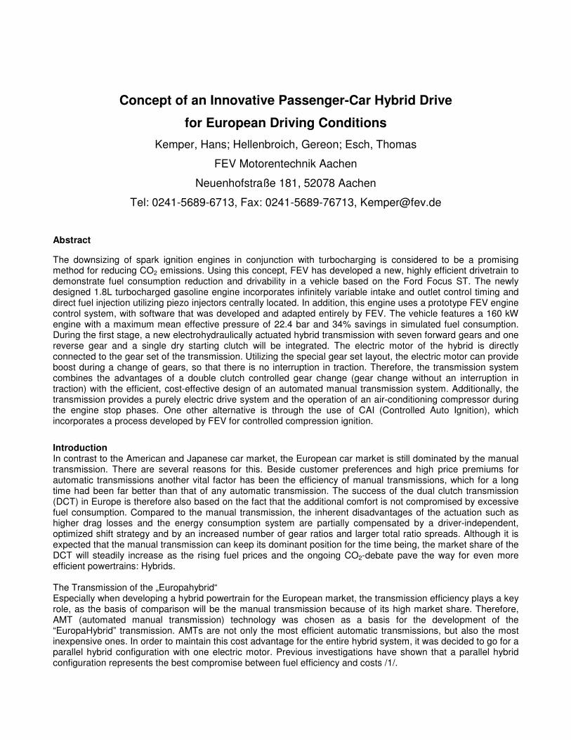
The main disadvantage of AMTs compared to DCTs or conventional automatic transmissions is the torque interruption during shifts. Because of this, the conventional AMT does not fulfill today’s comfort requirements and is only found in vehicles of the compact- and sub-compact classes or in sports cars, where shift comfort does not play a key role. The basic idea of the “EuropaHybrid” is to bring back AMT technology by eliminating its torque interruption using the electric motor. In general, there are several different possibilities to integrate the electric motor into a parallel hybrid powertrain. Figure 1 shows concepts where the electric motor is located either in front or behind a conventional AMT transmission. Only configuration “P3” allows for a torque support during shifts. However, only one fixed gear ratio is available for the electric motor.
CECE
EMEM
T/MT/M
+ EM can use gear ratios of transmission
- no torque support during shifts
1
CE – combustion engine
EM – electric motor
T/M - transmission
„P1“ or „P2“ configuration
CECE
T/MT/M
+ EM can provide torque support during shifts
- no gear ratios for EM => limited E-torque
2
EMEM
„P3“ configuration
CECE
T/MT/M
+ EM can provide torque support during shifts
- no gear ratios for EM => limited E-torque
2
EMEM
„P3“ configuration
CECE
T/MT/M
+ EM can provide torque support during shifts
- no gear ratios for EM => limited E-torque
2
EMEM
„P3“ configuration
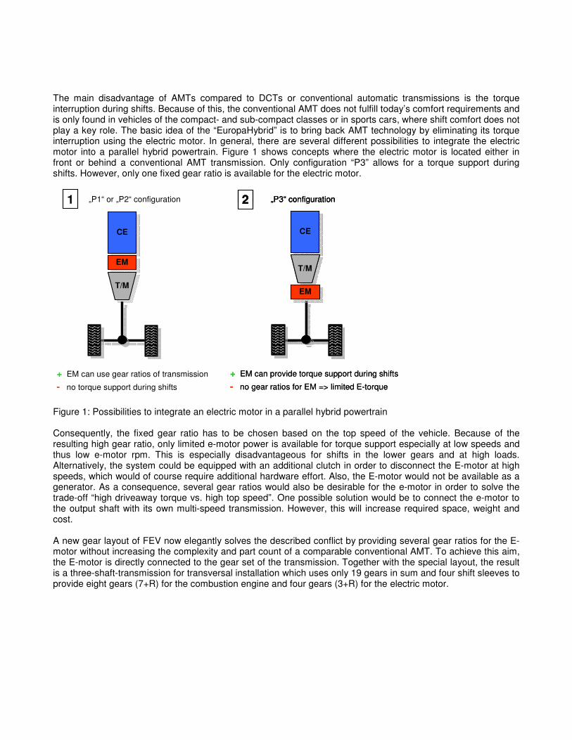
Figure 1: Possibilities to integrate an electric motor in a parallel hybrid powertrain Consequently, the fixed gear ratio has to be chosen based on the top speed of the vehicle. Because of the resulting high gear ratio, only limited e-motor power is available for torque support especially at low speeds and thus low e-motor rpm. This is especially disadvantageous for shifts in the lower gears and at high loads. Alternatively, the system could be equipped with an additional clutch in order to disconnect the E-motor at high speeds, which would of course require additional hardware effort. Also, the E-motor would not be available as a generator. As a consequence, several gear ratios would also be desirable for the e-motor in order to solve the trade-off “high driveaway torque vs. high top speed”. One possible solution would be to connect the e-motor to the output shaft with its own multi-speed transmission. However, this will increase required space, weight and cost. A new gear layout of FEV now elegantly solves the described conflict by providing several gear ratios for the E-motor without increasing the complexity and part count of a comparable conventional AMT. To achieve this aim, the E-motor is directly connected to the gear set of the transmission. Together with the special layout, the result is a three-shaft-transmission for transversal installation which uses only 19 gears in sum and four shift sleeves to provide eight gears (7+R) for the combustion engine and four gears (3+R) for the electric motor.
CECE
EMEM
T/MT/MT/MT/M
+ EM can provide torque support during shifts
+ EM can use gear ratios of transmission
- increased complexity, weight and cost
3
CECE
EMEMT/MT/M
+ EM can provide torque support during shifts
+ EM can use gear ratios of transmission
+ same mechanical complexity as standard AMT
7H7H--AMT AMT conceptconcept7H7H--AMT AMT conceptconcept7H7H--AMT AMT conceptconcept
Figure 2: FEVs new 7+R Hybrid AMT concept In the following table, some characteristic values of the FEV prototype are compared to a hybrid transmission concept based on a seven-speed DCT with dry clutches.
7-speed DCT hybrid FEV 7H-AMT
Example for a DCT hybrid concept with connection of e-motor to one of the input-shafts Prototype
Number of gear ratios / combustion engine 7+R 7+R
Number of gear ratios / electric motor 4 or 3+R (depending on e-motor connection) 3+R
Power capacity 125 kW 160 kW + 35 kW (EM)
Torque capacity 250 Nm 320 Nm + 70 Nm (EM)
Number of shafts 5 3
Number of gears 20 w/o connection of e-motor 19 including connection of e-motor
Number of shift-forks / shift-sleeves 4/5 4/4
Number of actuators 4 + 2 (dual dry clutches) 4 + 1 (single dry clutch)
Mass1 77 kg 85 kg (transmission only: 59 kg)
Parking lock yes (clutches normally open) no (clutch normally closed)
Installation length 369 mm 356 mm
1 including actuation and dual mass flywheel, w/o e-motor and air contidioning compressor
Concept
Table 1: Comparison of 7-speed DCT hybrid and FEVs 7H-AMT concept The comparison shows the simple construction of the FEV prototype and its excellent torque-to-weight-ratio. As an additional feature, a conventional air conditioning compressor can be connected to one of the transmission input shafts via a belt drive. During start-stop phases, the E-motor of the hybrid system can then be used to drive the compressor thus eliminating the need for a separate electric motor just for the A/C-compressor. Top speed during all-electric driving is only limited by the power of the electric motor. Furthermore, no shifts need to be performed up to a speed of around 70 km/h. Shift comfort of FEVs new concept is of course highly dependant on the power of the E-motor vs. the power of the combustion engine. By concept, no torque reduction during shifts will be noticeable up to the short time peak power of the electric motor, which will be around 60 kW for the “EuropaHybrid”. Above that power, a torque reduction during shifts will occur. However, due to the gear layout, the inertia which has to be synchronized during shifts is very low. This will allow for very short, sporty shifts thus reducing the influence of the torque reduction.
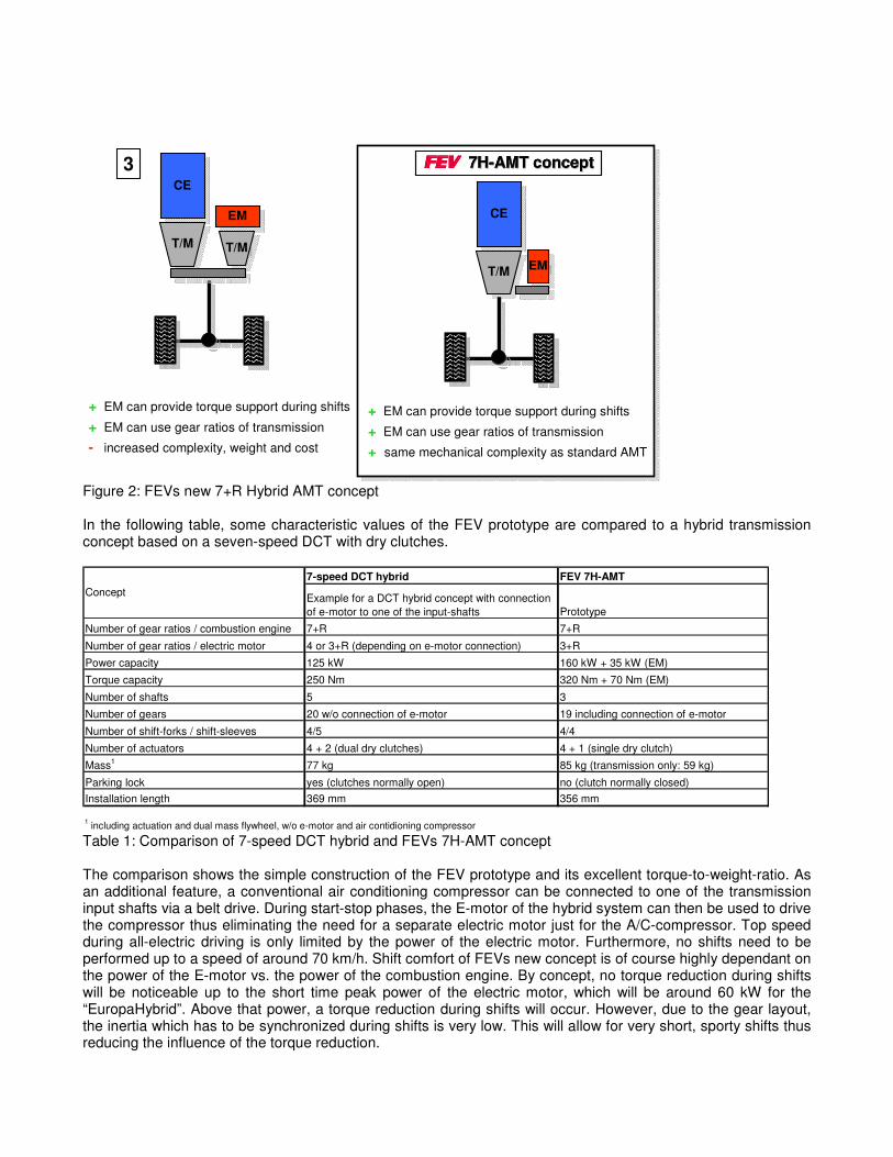
Figure 3: Design of FEVs 7H AMT Controlled Auto Ignition Combustion in Combination with a Hybrid Drivetrain The challenge in the reduction of CO2 emissions of gasoline engines leads to the implementation of new technologies. The project’s objective is to develop a state of the art hybrid drivetrain that joins premium driveability with a 30 % cut down in fuel consumption in contrast to a conventional gasoline engine. Additionally a ‘Near Zero Emission Mode’ for intra-urban operation has to be assured. One promising future combustion process that has the ability to assure the defined objectives is the controlled auto ignition (CAI) of the fuel air mixture. Previous profound investigations at FEV have proven very high potential of CAI to reduce fuel consumption and NOx emissions at part load conditions. The controlled self ignition of a highly diluted, homogeneous cylinder charge permits a strong reduction of gas exchange losses and an improvement of thermodynamic properties of the cylinder mixture. Both lead to lower fuel consumption and therefore less CO2 emissions. Peak and post combustion temperatures are explicitly lower in contrast to conventional spark ignited combustion (< 2000 K). As a result, NO emissions are decreased dramatically, since the chemical reactions for the creation of Zeldovich-NO (equals about 90 to 95 % of the total NO emissions of conventional gasoline engines) are just weakly active. Despite lean operation, exhaust after treatment can be obtained with a conventional three way catalyst compared to stratified lean burn combustion systems. Self ignition is determined by three factors. First reaction kinetics, which are influenced by fuel attributes and the amount of residual gas trapped in the cylinder. Second by the temperature of the mixture, that is primarily affected by the amount of internal EGR, injection timing, compression ratio, etc. Third by stratification, that is determined by the used EGR strategy. The dilution of the cylinder charge is obtained by a strongly lean mixture and very high internal EGR amounts in order to reach the self ignition temperature. Because of the high homogeneity of the charge, self ignition occurs at several spots in the combustion chamber at the same time enabling a fast burning duration. In that respect the CAI mode is limited to part load operation, due to the strong pressure rise at high loads. Misfiring terminates the possible range towards lower loads, as exhaust temperatures are not high enough to promote self ignition. Beyond the CAI operation map conventional spark ignition (SI) is required. Challenges exist in the implementation of a closed-loop control for changing the two combustion modes.
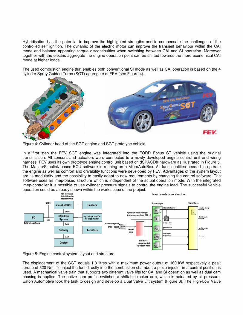
Hybridisation has the potential to improve the highlighted strengths and to compensate the challenges of the controlled self ignition. The dynamic of the electric motor can improve the transient behaviour within the CAI mode and balance appearing torque discontinuities when switching between CAI and SI operation. Moreover together with the electric aggregate the engine operation point can be shifted towards the more economical CAI mode at higher loads. The used combustion engine that enables both conventional SI mode as well as CAI operation is based on the 4 cylinder Spray Guided Turbo (SGT) aggregate of FEV (see Figure 4).
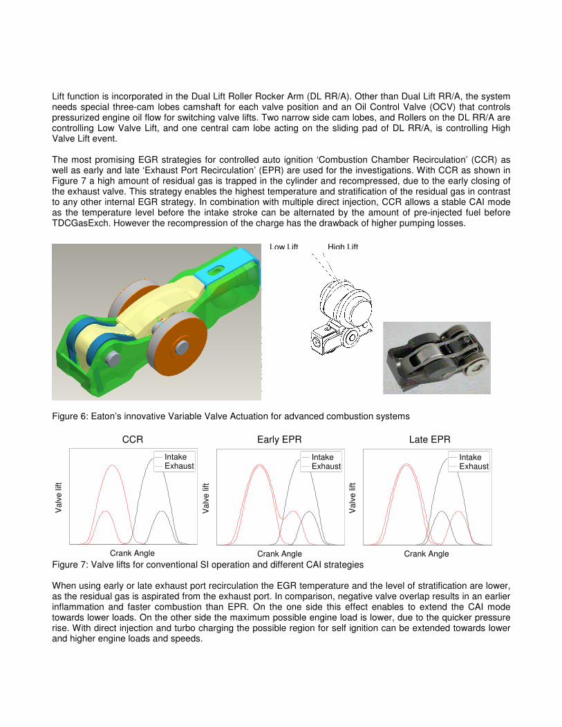
Figure 4: Cylinder head of the SGT engine and SGT prototype vehicle In a first step the FEV SGT engine was integrated into the FORD Focus ST vehicle using the original transmission. All sensors and actuators were connected to a newly developed engine control unit and wiring harness. FEV uses its own prototype engine control unit based on dSPACE® hardware as illustrated in Figure 5. The Matlab/Simulink based ECU software is running on a MicroAutoBox. All functionalities needed to operate the engine as well as comfort and drivability functions were developed by FEV. Advantages of the system layout are its modularity and the possibility to easily adapt to new requirements by changing the control software. The software uses an imep-based structure which is independent of the actual operation mode. With the integrated imep-controller it is possible to use cylinder pressure signals to control the engine load. The successful vehicle operation could be already shown within the work scope of the project.
MicroAutoBox
RapidPro
System
Gateway
Cockpit
PC
Sensors
Actuators
USB
LVDS
LVDS
CAN
CAN
FEV developedMatlab/Simulink
based software
Calibration software
high voltage amplifier
for piezo injectors
Figure 5: Engine control system layout and structure The displacement of the SGT equals 1.8 litres with a maximum power output of 160 kW respectively a peak torque of 320 Nm. To inject the fuel directly into the combustion chamber, a piezo injector in a central position is used. A mechanical valve train that supports two different valve lifts for CAI and SI operation as well as dual cam phasing is applied. The active cam profile switches a shiftable rocker arm, which is actuated by oil pressure. Eaton Automotive took the task to design and develop a Dual Valve Lift system (Figure 6). The High-Low Valve
pmi
N
η1
23i
pmi
Nλ
pmi
N
pmi
N
ZW
AGR
12
3
12
3
∗
pmi
Nxyz
12
3
Fahrpedal
Drehzahl
pmi
N
EZP
pmi-basiert
pmi
N
λ1
23
Wunsch-Mittel-druck
mL
Struktur istunabhängigvon derBetriebsart
Betriebsarten-manager
imep based control structure
accelerator pedal
engine speed
desired
imep
operation mode manager
(homogeneous, lean, CAI, …)
structure is
independent of
operation mode
indicated efficiency
air mass flow
base maps controllers
ignition angle
exhaust gas
recirculation
injection timing
throttle angle
ignition angle
…
Lift function is incorporated in the Dual Lift Roller Rocker Arm (DL RR/A). Other than Dual Lift RR/A, the system needs special three-cam lobes camshaft for each valve position and an Oil Control Valve (OCV) that controls pressurized engine oil flow for switching valve lifts. Two narrow side cam lobes, and Rollers on the DL RR/A are controlling Low Valve Lift, and one central cam lobe acting on the sliding pad of DL RR/A, is controlling High Valve Lift event. The most promising EGR strategies for controlled auto ignition ‘Combustion Chamber Recirculation’ (CCR) as well as early and late ‘Exhaust Port Recirculation’ (EPR) are used for the investigations. With CCR as shown in Figure 7 a high amount of residual gas is trapped in the cylinder and recompressed, due to the early closing of the exhaust valve. This strategy enables the highest temperature and stratification of the residual gas in contrast to any other internal EGR strategy. In combination with multiple direct injection, CCR allows a stable CAI mode as the temperature level before the intake stroke can be alternated by the amount of pre-injected fuel before TDCGasExch. However the recompression of the charge has the drawback of higher pumping losses.
Figure 6: Eaton’s innovative Variable Valve Actuation for advanced combustion systems
Figure 7: Valve lifts for conventional SI operation and different CAI strategies When using early or late exhaust port recirculation the EGR temperature and the level of stratification are lower, as the residual gas is aspirated from the exhaust port. In comparison, negative valve overlap results in an earlier inflammation and faster combustion than EPR. On the one side this effect enables to extend the CAI mode towards lower loads. On the other side the maximum possible engine load is lower, due to the quicker pressure rise. With direct injection and turbo charging the possible region for self ignition can be extended towards lower and higher engine loads and speeds.
Low Lift High Lift
Val
ve li
ft
Crank Angle
Intake Exhaust
Val
ve li
ft
Crank Angle
Intake Exhaust
Val
ve li
ft
Crank Angle
Intake Exhaust
CCR Early EPR Late EPR
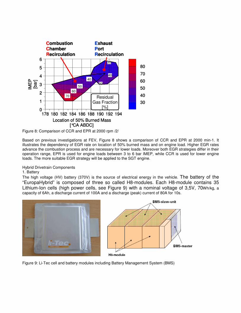
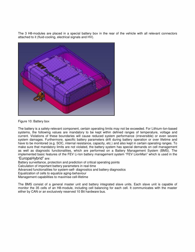
Figure 8: Comparison of CCR and EPR at 2000 rpm /2/ Based on previous investigations at FEV, Figure 8 shows a comparison of CCR and EPR at 2000 min-1. It illustrates the dependency of EGR rate on location of 50% burned mass and on engine load. Higher EGR rates advance the combustion process and are necessary for lower loads. Moreover both EGR strategies differ in their operation range, EPR is used for engine loads between 3 to 6 bar IMEP, while CCR is used for lower engine loads. The more suitable EGR strategy will be applied to the SGT engine. Hybrid Drivetrain Components 1. Battery The high voltage (HV) battery (370V) is the source of electrical energy in the vehicle. The battery of the “EuropaHybrid” is composed of three so called H8-modules. Each H8-module contains 35 Lithium-Ion cells (high power cells, see Figure 9) with a nominal voltage of 3,5V, 70Wh/kg, a capacity of 6Ah, a discharge current of 100A and a discharge (peak) current of 80A for 10s.
Figure 9: Li-Tec cell and battery modules including Battery Management System (BMS)
IME
P[b
ar]
0
1
2
3
4
5
6
Location of 50% Burned Mass[°CA ABDC]
178 180 182 184 186 188 190 192 194
30
50
40
70
60
50
40
ResidualGas Fraction
[%]30
40
50
60
70
80
Combustion ChamberRecirculation
ExhaustPort Recirculation
IME
P[b
ar]
0
1
2
3
4
5
6
Location of 50% Burned Mass[°CA ABDC]
178 180 182 184 186 188 190 192 194
30
50
40
70
60
50
40
ResidualGas Fraction
[%]30
40
50
60
70
80
Combustion ChamberRecirculation
ExhaustPort Recirculation
The 3 H8-modules are placed in a special battery box in the rear of the vehicle with all relevant connectors attached to it (fluid-cooling, electrical signals and HV).
Figure 10: Battery box The battery is a safety-relevant component, certain operating limits may not be exceeded. For Lithium-Ion-based systems, the following values are mandatory to be kept within defined ranges of temperature, voltage and current. Violations of these boundaries will cause reduced system performance (irreversible) or even severe system damages. Furthermore, specific battery parameters drift during battery operation or over lifetime and have to be monitored (e.g. SOC, internal resistance, capacity, etc.) and also kept in certain operating ranges. To make sure that mandatory limits are not violated, the battery system has special demands on cell management as well as diagnostic functionalities, which are performed on a Battery Management System (BMS). The implemented basic features of the FEV Li-Ion battery management system “FEV LiionMan” which is used in the “EuropaHybrid” are: Battery surveillance, protection and prediction of critical operating points Calculation of important battery parameters in real-time Advanced functionalities for system-self- diagnostics and battery diagnostics Equalization of cells to equalize aging-behaviour Management capabilities to maximise cell-lifetime The BMS consist of a general master unit and battery integrated slave units. Each slave unit is capable of monitor the 35 cells of an H8-module, including cell balancing for each cell. It communicates with the master either by CAN or an exclusively reserved 10 Bit hardware bus.
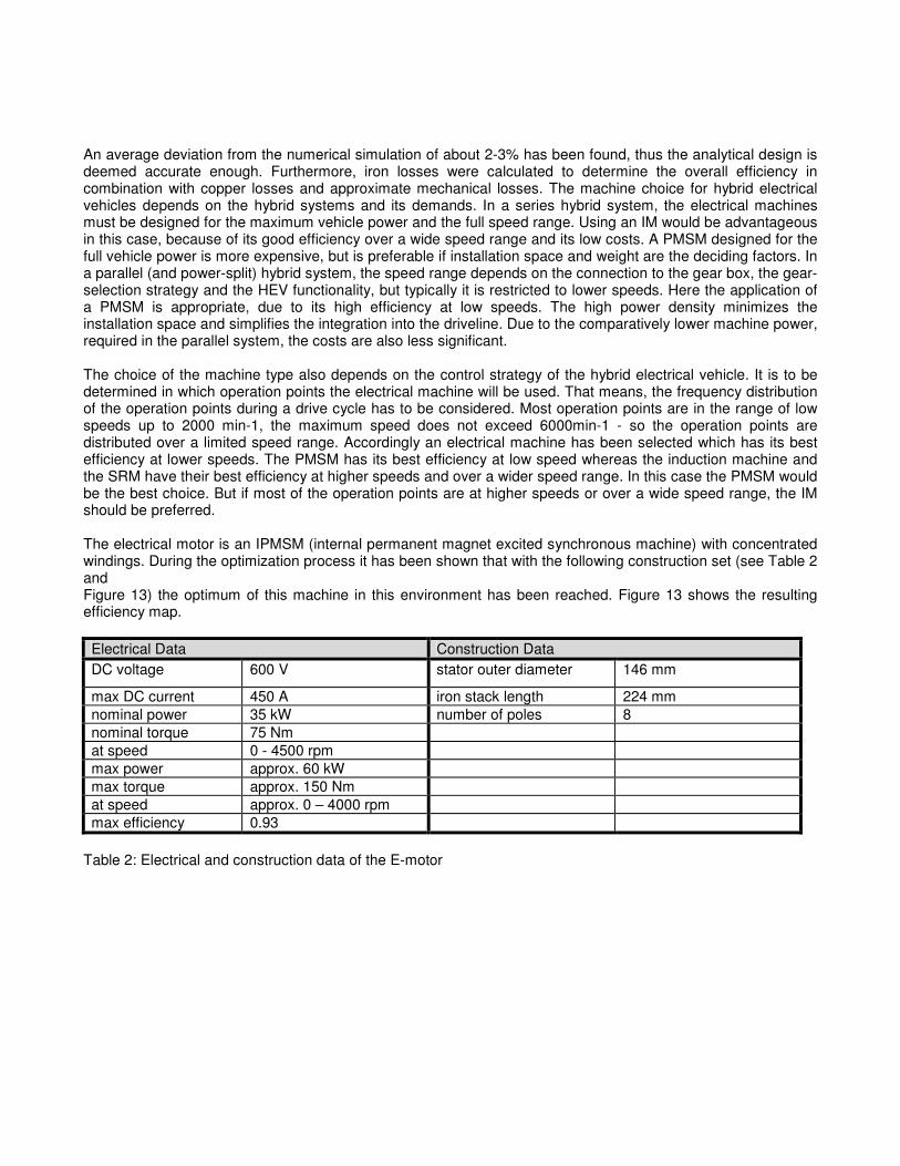
Figure 11: FEVs BMS Unit Another key-task is to guarantee sufficient cooling of the battery in all operating points. The battery of the “EuropaHybrid” is fluid-cooled (Refrigerant R134a). The H8-modules are connected to the existing vehicle climate circuit. The vehicle climate circuit is extended with a parallel battery cooling bypass as shown in Figure 12. The original and extended cooling circuits are switchable by solenoid valves. That ensures that the climate system capability can completely be dedicated to the battery system if necessary. This is due to safety reasons since the temperature is one of the ‘mandatory to be kept’-boundaries to avoid battery damages.
Figure 12: Principle sketch of the hydraulic circuit of the A/C system 2. E-Motor Considering the development and the prototype presentations of electrical and hybrid electrical vehicles over the last decade, one can see that several machine types were applied, the direct current machine (DC), the induction machine (IM), the permanent magnet excited synchronous machine (PMSM) and the switched reluctance machine (SRM). The application of all these machines suggests that they have advantages and disadvantages of their own which render them interesting in different hybrid vehicle concepts. To compare the power density, an analytical pre-design was performed for a nominal power of 30kW, a nominal speed of 3000min-1 as well as a nominal line voltage of 400V. These values are based on an average of commonly applied machines in HEVs. To assure a maximum utilization and a sufficient comparability, a quadratic design was used for each machine. The analytical pre-designs were validated by finite element computations (FE). Parameterized geometrical models were used to generate the FE-models based on the geometry determined by the analytical design. By this means, the analytically calculated values of the induced voltage, the torque, the power and the expected air-gap induction were verified.
An average deviation from the numerical simulation of about 2-3% has been found, thus the analytical design is deemed accurate enough. Furthermore, iron losses were calculated to determine the overall efficiency in combination with copper losses and approximate mechanical losses. The machine choice for hybrid electrical vehicles depends on the hybrid systems and its demands. In a series hybrid system, the electrical machines must be designed for the maximum vehicle power and the full speed range. Using an IM would be advantageous in this case, because of its good efficiency over a wide speed range and its low costs. A PMSM designed for the full vehicle power is more expensive, but is preferable if installation space and weight are the deciding factors. In a parallel (and power-split) hybrid system, the speed range depends on the connection to the gear box, the gear-selection strategy and the HEV functionality, but typically it is restricted to lower speeds. Here the application of a PMSM is appropriate, due to its high efficiency at low speeds. The high power density minimizes the installation space and simplifies the integration into the driveline. Due to the comparatively lower machine power, required in the parallel system, the costs are also less significant. The choice of the machine type also depends on the control strategy of the hybrid electrical vehicle. It is to be determined in which operation points the electrical machine will be used. That means, the frequency distribution of the operation points during a drive cycle has to be considered. Most operation points are in the range of low speeds up to 2000 min-1, the maximum speed does not exceed 6000min-1 - so the operation points are distributed over a limited speed range. Accordingly an electrical machine has been selected which has its best efficiency at lower speeds. The PMSM has its best efficiency at low speed whereas the induction machine and the SRM have their best efficiency at higher speeds and over a wider speed range. In this case the PMSM would be the best choice. But if most of the operation points are at higher speeds or over a wide speed range, the IM should be preferred. The electrical motor is an IPMSM (internal permanent magnet excited synchronous machine) with concentrated windings. During the optimization process it has been shown that with the following construction set (see Table 2 and Figure 13) the optimum of this machine in this environment has been reached. Figure 13 shows the resulting efficiency map. Electrical Data Construction Data DC voltage 600 V stator outer diameter 146 mm
max DC current 450 A iron stack length 224 mm nominal power 35 kW number of poles 8 nominal torque 75 Nm at speed 0 - 4500 rpm max power approx. 60 kW max torque approx. 150 Nm at speed approx. 0 – 4000 rpm max efficiency 0.93
Table 2: Electrical and construction data of the E-motor
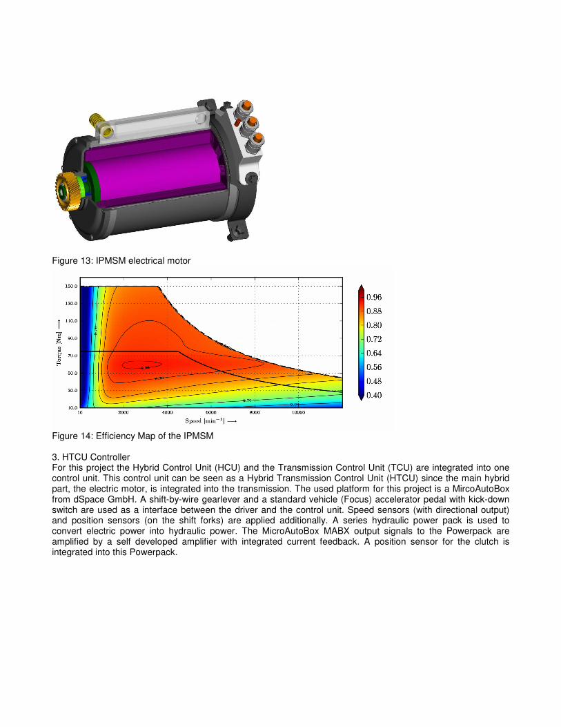
Figure 13: IPMSM electrical motor
Figure 14: Efficiency Map of the IPMSM 3. HTCU Controller For this project the Hybrid Control Unit (HCU) and the Transmission Control Unit (TCU) are integrated into one control unit. This control unit can be seen as a Hybrid Transmission Control Unit (HTCU) since the main hybrid part, the electric motor, is integrated into the transmission. The used platform for this project is a MircoAutoBox from dSpace GmbH. A shift-by-wire gearlever and a standard vehicle (Focus) accelerator pedal with kick-down switch are used as a interface between the driver and the control unit. Speed sensors (with directional output) and position sensors (on the shift forks) are applied additionally. A series hydraulic power pack is used to convert electric power into hydraulic power. The MicroAutoBox MABX output signals to the Powerpack are amplified by a self developed amplifier with integrated current feedback. A position sensor for the clutch is integrated into this Powerpack.
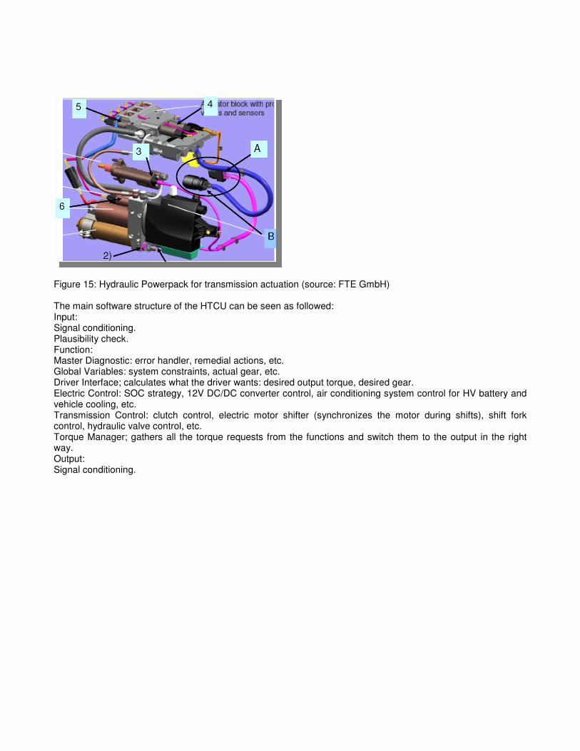
Figure 15: Hydraulic Powerpack for transmission actuation (source: FTE GmbH) The main software structure of the HTCU can be seen as followed: Input: Signal conditioning. Plausibility check. Function: Master Diagnostic: error handler, remedial actions, etc. Global Variables: system constraints, actual gear, etc. Driver Interface; calculates what the driver wants: desired output torque, desired gear. Electric Control: SOC strategy, 12V DC/DC converter control, air conditioning system control for HV battery and vehicle cooling, etc. Transmission Control: clutch control, electric motor shifter (synchronizes the motor during shifts), shift fork control, hydraulic valve control, etc. Torque Manager; gathers all the torque requests from the functions and switch them to the output in the right way. Output: Signal conditioning.
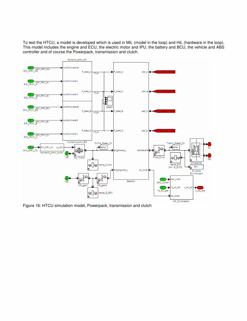
To test the HTCU, a model is developed which is used in MiL (model in the loop) and HiL (hardware in the loop). This model includes the engine and ECU, the electric motor and IPU, the battery and BCU, the vehicle and ABS controller and of course the Powerpack, transmission and clutch.
Figure 16: HTCU simulation model, Powerpack, transmission and clutch

To simulate shafts SimDriveLine is used. In the SimDriveLine library are included; friction clutch, differential, gear, torque actuator, motion sensor, inertia and vehicle. Unfortunately SimDriveLine does not offer a synchronizer. Therefore it is simulated with Simulink in this project. To integrate the Simulink synchronizer into the SimDriveLine model, a friction clutch is used as interface. Also the simulated synchronizer outputs the position of the shift fork, which is used as a main input on the transmission shift fork control.
Figure 17: Simulation model “EuropaHybrid” transmission The main purposes of the project is a fuel efficient and drivable car with reproducible behavior. To demonstrate pure electrical drive, the maximum motor output is not limited, as would make sense from a fuel efficiency point of view. To limit pure electric drive during bench emission tests, limits other then power only are added to the
strategy. To optimize energy recuperation a special coast function is developed which enables pure electrical drive during coast down situations. As soon as the driver requests torque again, the engine is restarted. Because the engine has no starter, restart out of E-drive is only possible using the friction clutch. In this situation the transmission clutch control calculates the torque being drawn from the transmission. This deficit torque is added on to the electric motor torque which has a special overboost function (allowing twice the power for one second). Safety Concept Development process Talking about safety of hybrid electric vehicles, one has to consider two main aspects on top of the safety aspects already taken into account in conventional vehicles. On the one hand, the implementation of high voltage components forces the vehicle designers to pay particularly attention to all hazards linked to these components such as high voltage access by any third party, may it be direct or indirect (i.e. through a loss of insulation), arcing, thermal runaway of Li-Ion battery, etc. In addition, the new functions in the control of the vehicle such as gearbox actuation or torque split between E-motor and internal combustion engine further increases the complexity of electronic control unit networking, hence rising the need to deeply study the functional safety of these new functions. The whole safety concept of the vehicle (i.e. addressing both HV related issues and functional safety related issues) was obtained using a risk based approach. The main steps of the risk based safety concept development are as follows: Item definition: Aims at defining the system with regard to its functionality, interfaces, environmental conditions, etc. Hazard analysis and risk assessment: The hazards associated to the vehicle are assessed through their probability of exposure, their severity and controllability. For each hazard studied, a general Safety goal is specified at the vehicle level. Example of a safety goal would be: “Direct access to any HV potential shall be prevented”, or for functional safety: “The vehicle shall not move more than 10 cm in case of unintended rotation of the E-machine in stop phase”. In addition, for functional safety related aspects, this hazard analysis and risk assessments yields the Automotive Safety Integrity Level (ASIL) as defined in ISO CD 26262-1. Specification of general safety requirements: For each safety goal defined, and according to the safety integrity required (i.e. according to the risk reduction level required), some general safety related requirements are established for all components concerned by the safety goal in focus. These general safety requirements are divided into two parts, one dealing with purely HV related requirements and the other one related to functional safety aspects. Establishment of detailed safety specifications: The general safety requirements at the vehicle level are distributed to the responsible stakeholders of the different vehicle’s sub-systems. These responsible have to write down the technical specification for the solution they chose to follow to fulfil the general safety goal. These specifications are then the input for the development phase during which the different safety functions are assessed at different steps, such as testing, verification and validations phases. 1. High voltage safety concept The high voltage safety concept developed for the “EuropaHybrid” vehicle addresses all issues linked to electrical hazards for Class B (Voltage level > 60VDC/25VAC) components such as: Direct access to HV Indirect access to HV Incorrect HV connection Arcing Inverted connection
Heat-release of HV components Thermal runaway of HV battery Release of toxic substance Gas Electrolyte
The developers of the high voltage safety concept followed a three step risk reduction principle which gave birth to a three level high voltage safety concept. These three levels are: Safe design of the HV components
The measures taken at this level mainly focus on the design of the high voltage components themselves. For example, all high voltage components shall be covered in order to prevent direct access to high voltage potential, they should fulfil the appropriate IP protection class. The HV connectors shall be mechanically encoded in order to prevent inverted connections. The HV network shall be galvanically isolated from the low voltage boardnet, etc. Use of protective devices The second level consists in adding the necessary protective devices such as a fuse in the HV battery to protect against over-current, a service plug, still in the HV battery to disconnect the HV network during service. A pilot line, going through all HV component’s cover open detect switches and HV connectors is also implemented to immediately open the HV connectors in case of direct access to HV is possible through opening of a HV component’s cover or in case of arcing due to a wrong connection of any HV connector. At this level, some measures may also be taken by dedicated control units such as the Battery Monitoring System which has to ensure that the HV battery is still operating in a non-hazardous region (over temperature, over voltage, etc.) or which has to monitor the insulation level of the HV boardnet against the LV boardnet. Warning measures The last level of the high voltage safety concept is the warning level which aim is to give an obvious warning to the user, in order that he can also take some risk reduction measures. Examples of the measures taken at this level are the HV warning signs put on every HV component’s cover and the notes written down in the user and service manual aiming at drawing the attention on the particular aspects of hybrid electric vehicles. Another warning measure taken at his level is the orange colour used to cover all HV cables in the vehicle. 2. Functional safety concept The functional safety concept developed for the “EuropaHybrid” vehicle is based on the outcome of the risk analysis as already explained, in particular on the safety goal and the safety integrity as well as on the defined safe state for the function in focus. As the vehicle is intended to be a demonstrator vehicle and as the risk analysis showed no need for “fail functional” architectures, as one could expect from a steer-by-wire system for example, the designers of the functional safety concept have focused on “fail safe” architectures. The aim of this concept is to detect any potentially hazardous failure in the system and to bring it to a safe state. The designers of the vehicle have selected two types of emergency stops. On the one hand, a hardware emergency stop, actuated through red emergency stop switches placed within driver’s reach and under the vehicle hood (or through the pilot line, as explained in Section 1.2) which aim is to immediately shutdown the vehicle through opening the HV relays and cutting fuel injection and ignition. Next to this hardware “last chance” emergency stop, the designers of the safety concept are working on a software emergency stop solution, which aim is to bring the system to a safe state in a controlled way. In order to do so, many mechanisms are used to detect potentially hazardous failures, such as cycle counters and checksum for the CAN communication and monitoring of the sensors and actuators through plausibility checks and redundant sensors for the important I/Os. The different control units in the system are responsible for the safety of their sub-systems, the ECU for the internal combustion engine, the IPU for the E-machine, the BMS for the HV battery, etc. The hybrid controller, HCU, is responsible for the overall monitoring of the system, being a kind of redundant safety measures in case where the control of any sub-system would have failed. Each control unit is then responsible for detecting any failure of their sub-system and the other control units are responsible for checking the correct functionality of the control unit of this sub-system through the monitoring of the CAN communication. Each control unit is able to initiate an emergency stop through an additional hardware hand shake line, a kind of redundancy to the CAN communication checks implemented. Summary Compared to the base vehicle, Ford Focus ST, equipped with a 2.5 l turbocharged, port fuel injected (PFI) engine and manual transmission, computer simulations show for FEVs Spray Guided Turbo Demonstrator Vehicle a saving in fuel consumption for the downsizing concept with a 1.8L turbocharged engine and shift operation of 26%. For the new FEVs 7H AMT hybrid powertrain a fuel consumption reduction in the NEDC
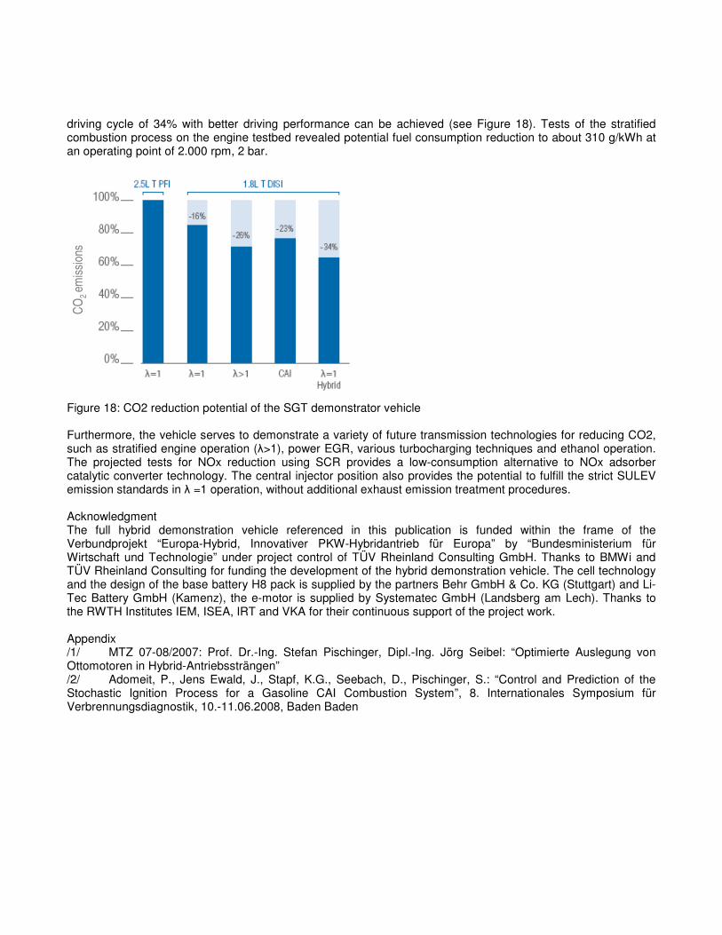
driving cycle of 34% with better driving performance can be achieved (see Figure 18). Tests of the stratified combustion process on the engine testbed revealed potential fuel consumption reduction to about 310 g/kWh at an operating point of 2.000 rpm, 2 bar.
CO
2 e
mis
sio
ns
Figure 18: CO2 reduction potential of the SGT demonstrator vehicle Furthermore, the vehicle serves to demonstrate a variety of future transmission technologies for reducing CO2, such as stratified engine operation (λ>1), power EGR, various turbocharging techniques and ethanol operation. The projected tests for NOx reduction using SCR provides a low-consumption alternative to NOx adsorber catalytic converter technology. The central injector position also provides the potential to fulfill the strict SULEV emission standards in λ =1 operation, without additional exhaust emission treatment procedures. Acknowledgment The full hybrid demonstration vehicle referenced in this publication is funded within the frame of the Verbundprojekt “Europa-Hybrid, Innovativer PKW-Hybridantrieb für Europa” by “Bundesministerium für Wirtschaft und Technologie” under project control of TÜV Rheinland Consulting GmbH. Thanks to BMWi and TÜV Rheinland Consulting for funding the development of the hybrid demonstration vehicle. The cell technology and the design of the base battery H8 pack is supplied by the partners Behr GmbH & Co. KG (Stuttgart) and Li-Tec Battery GmbH (Kamenz), the e-motor is supplied by Systematec GmbH (Landsberg am Lech). Thanks to the RWTH Institutes IEM, ISEA, IRT and VKA for their continuous support of the project work. Appendix /1/ MTZ 07-08/2007: Prof. Dr.-Ing. Stefan Pischinger, Dipl.-Ing. Jörg Seibel: “Optimierte Auslegung von Ottomotoren in Hybrid-Antriebssträngen” /2/ Adomeit, P., Jens Ewald, J., Stapf, K.G., Seebach, D., Pischinger, S.: “Control and Prediction of the Stochastic Ignition Process for a Gasoline CAI Combustion System”, 8. Internationales Symposium für Verbrennungsdiagnostik, 10.-11.06.2008, Baden Baden