it's really not a rendering bug, you see… andrew...
TRANSCRIPT
IEEE Computer Graphics and Applications September 1996 21
Most rendering algorithms
deliberately employ
approximations and other
shortcuts for efficiency.
These economies—not
coding errors—produce
characteristic image artifacts.
This article classifies the
best-known varieties.
rtifacts of rendering, though oftentreated on a case-by-case basis, havenot yet been treated as a class. We
propose the non-exhaustive taxonomy shown in Table 1.Each category is treated at greater length in the followingsections, and some workarounds are provided.
Surface acneWhen ray tracing, you are intersecting rays with
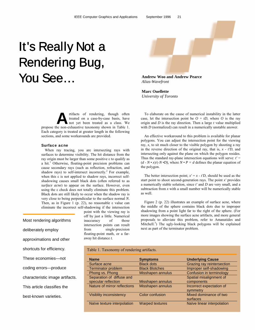
surfaces to determine visibility. The hit distance from theray origin must be larger than some positive ε to qualify asa hit.1 Otherwise, floating-point precision problems cancause secondary rays (such as reflection, refraction, andshadow rays) to self-intersect incorrectly.2 For example,when this ε is not applied to shadow rays, incorrect self-shadowing causes small black dots (often referred to assurface acne) to appear on the surface. However, evenusing the ε check does not totally eliminate this problem.Black dots are still likely to occur when the shadow ray isvery close to being perpendicular to the surface normal N.Then, as in Figure 1 (p. 22), no reasonable ε value caneliminate the incorrect self-shadowing if the intersection
point with the viewing ray isoff by just a little. Numericalinaccuracy of thoseintersection points can resultfrom single-precisionfloating-point math, or a far-away hit distance t.
To elaborate on the cause of numerical instability in the lattercase, let the intersection point be O + tD, where O is the rayorigin and D is the ray direction. Then a large t value multipliedwith D (normalized) can result in a numerically unstable answer.
An effective workaround to this problem is available for planarpolygons. You can adjust the intersection point for the viewingray, x, to sit much closer to the visible polygon by shooting a rayin the reverse direction of the original ray, that is, x - t'D, andintersecting only against the plane on which the polygon resides.Thus the standard ray-plane intersection equations will serve: t' =(d - N • x)/(-N •D), where N • P = d defines the planar equation ofthe polygon.
The better intersection point; x' = x - t'D, should be used as thestart point to shoot second-generation rays. The point x' providesa numerically stable solution, since t' and D are very small, and asubtraction from x with a small number will be numerically stableas well.
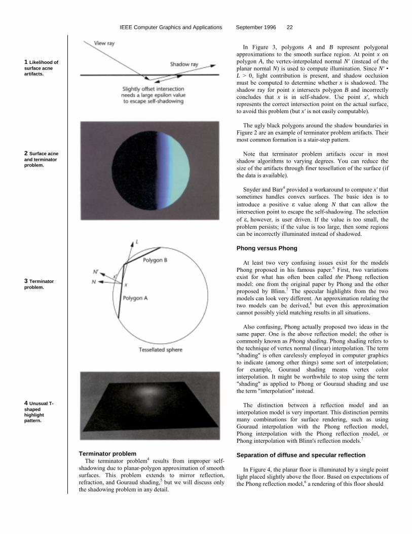
Figure 2 (p. 22) illustrates an example of surface acne, wherethe middle of the sphere contains black dots due to impropershadowing from a point light far to the right of the sphere. (Formore images showing the surface acne artifacts, and more generalproposals to alleviate this problem, refer to Amanatides andMitchell.3) The ugly-looking black polygons will be explainednext as part of the terminator problem.
A
It's Really Not aIt's Really Not aIt's Really Not aIt's Really Not aRendering Bug,Rendering Bug,Rendering Bug,Rendering Bug,You See…You See…You See…You See… Andrew Woo and Andrew Pearce
Alias-Wavefront
Marc OuelletteUniversity of Toronto
Table 1. Taxonomy of rendering artifacts.
Name Symptoms Underlying CauseSurface acne Black dots Grazing ray reintersectionTerminator problem Black Blotches Improper self-shadowingPhong vs. Phong Misshapen annulus Confusion in terminologySeparation of diffuse andspecular reflection Misshapen annulus
Spatial misalignment ofcomponents
Nature of mirror reflections Misshapen annulus Incorrect expectation ofsymmetry
Visiblity inconsistency Color confusion Mixed dominance of twosurfaces
Naïve texture interpolation Warped textures Naïve linear interpolation
IEEE Computer Graphics and Applications September 1996 22
1 Likelihood ofsurface acneartifacts.
2 Surface acneand terminatorproblem.
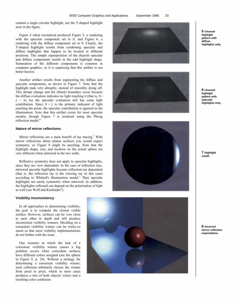
3 Terminatorproblem.
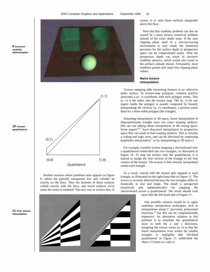
4 Unusual T-shapedhighlightpattern.
Terminator problemThe terminator problem4 results from improper self-
shadowing due to planar-polygon approximation of smoothsurfaces. This problem extends to mirror reflection,refraction, and Gouraud shading,5 but we will discuss onlythe shadowing problem in any detail.
In Figure 3, polygons A and B represent polygonalapproximations to the smooth surface region. At point x onpolygon A, the vertex-interpolated normal N' (instead of theplanar normal N) is used to compute illumination. Since N' •L > 0, light contribution is present, and shadow occlusionmust be computed to determine whether x is shadowed. Theshadow ray for point x intersects polygon B and incorrectlyconcludes that x is in self-shadow. Use point x', whichrepresents the correct intersection point on the actual surface,to avoid this problem (but x' is not easily computable).
The ugly black polygons around the shadow boundaries inFigure 2 are an example of terminator problem artifacts. Theirmost common formation is a stair-step pattern.
Note that terminator problem artifacts occur in mostshadow algorithms to varying degrees. You can reduce thesize of the artifacts through finer tessellation of the surface (ifthe data is available).
Snyder and Barr4 provided a workaround to compute x' thatsometimes handles convex surfaces. The basic idea is tointroduce a positive ε value along N that can allow theintersection point to escape the self-shadowing. The selectionof ε, however, is user driven. If the value is too small, theproblem persists; if the value is too large, then some regionscan be incorrectly illuminated instead of shadowed.
Phong versus Phong
At least two very confusing issues exist for the modelsPhong proposed in his famous paper.6 First, two variationsexist for what has often been called the Phong reflectionmodel: one from the original paper by Phong and the otherproposed by Blinn.7 The specular highlights from the twomodels can look very different. An approximation relating thetwo models can be derived,8 but even this approximationcannot possibly yield matching results in all situations.
Also confusing, Phong actually proposed two ideas in thesame paper. One is the above reflection model; the other iscommonly known as Phong shading. Phong shading refers tothe technique of vertex normal (linear) interpolation. The term"shading" is often carelessly employed in computer graphicsto indicate (among other things) some sort of interpolation;for example, Gouraud shading means vertex colorinterpolation. It might be worthwhile to stop using the term"shading" as applied to Phong or Gouraud shading and usethe term "interpolation" instead.
The distinction between a reflection model and aninterpolation model is very important. This distinction permitsmany combinations for surface rendering, such as usingGouraud interpolation with the Phong reflection model,Phong interpolation with the Phong reflection model, orPhong interpolation with Blinn's reflection models.7
Separation of diffuse and specular reflection
In Figure 4, the planar floor is illuminated by a single pointlight placed slightly above the floor. Based on expectations ofthe Phong reflection model,6 a rendering of this floor should
IEEE Computer Graphics and Applications September 1996 23
contain a single circular highlight, not the T-shaped highlightseen in the figure.
Figure 4 when rerendered produced Figure 5, a renderingwith the specular component set to 0, and Figure 6, arendering with the diffuse component set to 0. Clearly, theT-shaped highlight results from combining specular anddiffuse highlights that happen to be located at differentpositions. The simple superposition of the disjoint specularand diffuse components results in the odd highlight shape.Summation of the different components is common incomputer graphics, so it is surprising that this artifact is notbetter known.
Another artifact results from segmenting the diffuse andspecular components, as shown in Figure 7. Note that thehighlight ends very abruptly, instead of smoothly dying off.This abrupt change and the (black) boundary occur becausethe diffuse evaluation indicates no light reaching it (that is, N •L < 0), but the specular evaluation still has some lightcontribution. Since N • L is the primary indicator of lightreaching the point, the specular contribution is ignored in theillumination. Note that this artifact exists for most specularmodels, though Figure 7 is rendered using the Phongreflection model.6
Nature of mirror reflections
Mirror reflections are a main benefit of ray tracing.1 Withmirror reflections about planar surfaces you would expectsymmetry, so Figure 8 might be puzzling. Note that thehighlight shape, size, and location on the actual sphere arevery different when mirrored in the two walls.
Reflective symmetry does not apply to specular highlights,since they are view dependent. In the case of reflection rays,mirrored specular highlights become reflection-ray dependent(that is, the reflection ray is the viewing ray in this case)according to Whitted's illumination model.1 Thus specularhighlights are rarely symmetric when mirrored. In addition,the highlights reflected can depend on the polarization of lightas well (see Wolf and Kurlander9).
Visibility inconsistency
In all approaches to determining visibility,the goal is to compute the closest visiblesurface. However, surfaces can be very closeto each other in depth and still produceinconsistent visibility winners. Deciding on aconsistent visibility winner can be tricky-somuch so that most visibility implementationsdo not bother with the issue.
One scenario in which the lack of aconsistent visibility winner causes a bigproblem occurs when coincident surfaceshave different colors assigned (see the spherein Figure 9, p. 24). Without a strategy fordetermining a consistent visibility winner,such collisions arbitrarily choose the winnerfrom pixel to pixel, which in most casesproduces a mix of both objects' colors and aresulting color confusion.
5 Unusualhighlightpattern withdiffusehighlights only.
6 Unusualhighlightpattern withspecularhighlights only.
7 Highlightcutoff.
8 Incorrectmirror reflectionexpectations.
IEEE Computer Graphics and Applications September 1996 24
9 Incorrectvisibilitydetermination.
10 Unevenquadrilateral.
11 Poor textureinterpolation.
course, is to raise those surfaces marginally
Another scenario where problems arise appears in Figure9, where the partially transparent box and cylinder sitexactly on the floor. Thus the bottoms of those surfacescollide exactly with the floor, and weird artifacts occurwhen the scene is rendered. The easy way to resolve this, of
above the floor.
Note that this visibility problem can also becaused by a more serious numerical probleminstead of the exact depth issue. If the nearclipping plane used in a non-ray-tracingenvironment is very small, the numericalprecision for the surface depth in perspectivespace can be compromised easily. Then theperspective depth can result in incorrectvisibility answers, which would also result inthe artifacts already shown. Fortunately, mostrenderers permit user input into clipping planevalues.
Naive textureinterpolation
Texture mapping adds interesting features to an otherwisematte surface. To texture-map polygons, common practiceassociates a (u, v) coordinate with each polygon vertex. This(u, v) is the index into the texture map. The (u, v) for anyregion inside the polygon is usually computed by linearlyinterpolating the vertices' (u, v) coordinates, a process easilydone for a three-sided polygon (the triangle).
Assuming interpolation in 3D space, linear interpolation ofdisproportionate triangle sizes can cause warping artifacts.(We are not talking about interpolation in the wrong space.Some papers10,11 have discussed interpolation in perspectivespace that can result in bad warping artifacts. This is actuallya coding and logic error, and can be alleviated by employinghyperbolic interpolation11 or by interpolating in 3D space.)
For example, consider texture mapping a checkerboard ontoa quadrilateral subdivided into two triangles, as illustrated inFigure 10. To map the texture onto the quadrilateral, it isnatural to assign the four vertices of the triangle to the fourcorners of the texture. The texture is then linearly interpolatedwithin each triangle.
As a result, exactly half the texture gets mapped to eachtriangle, as illustrated on the right-hand side of Figure 11. Thetexture is severely distorted because the two triangles differ sodrastically in size and shape. The result is unexpected(intuitively and mathematically) for mapping thecheckerboard across a quadrilateral. The result should look
more like the left-hand side of Figure 11.
One possible solution would be to applynonlinear interpolation techniques, such asinterpolation using C1 piecewise polynomialfunctions,12 but this can be computationallyexpensive. An alternative solution to thisproblem is to tessellate the quadrilateralmore in both the u and v directions,assigning the correct vertex (u, v) so that thelinear interpolation error within the smallertriangles is negligible (the left-handquadrilateral in Figure 11 subdivided theobject 15 times in u and v).
IEEE Computer Graphics and Applications September 1996 25
If you continue to use linear interpolation, itsunfortunate limitations require an additional criterion forgood polygon reduction and tessellation algorithms whentexture mapping is involved. For tessellation algorithms,the poor texture interpolation problem is avoided byproducing evenly sized polygons. For reduction orsimplification algorithms, it is best to consider thelinearity of the (u, v) coordinates before consideringsimplification of the region.
Conclusions
We wrote this article in hopes of saving programmersa lot of time debugging something that is really not abug, but instead a limitation of the algorithm. Ourtaxonomy is not exhaustive, but it does include manycommon rendering problems that we have encounteredover the years.
Most of these limitations can be circumvented withthe proposed solutions. In reality, there are moreworkarounds than true solutions. This imbalancewarrants more research into proper solutions to these andsimilar problems.
Acknowledgments
Many thanks to Changyaw Wang, Eugene Fiume,Atjeng Gunawan, and Alan Paeth for proofreading thisarticle and providing useful suggestions. Thanks also goto the reviewers for their useful comments.
References
1. T. Whitted, "An Improved Illumination for Shaded Display," Comm.ACM, Vol. 23, No. 6, June 1980, pp. 343-349.
2. E. Haines, Essential Ray Tracing Algorithms, An Introduction to RayTracing, Academic Press, Cambridge, Mass., 1989, pp. 46-47.
3. J. Amanatides and D. Mitchell, "Some Regularization Problems inRay Tracing," Graphics Interface, May 1990, pp. 221-228.
4. J. Snyder and A. Barr, "Ray Tracing Complex Models ContainingSurface Tessellations," Computer Graphics, Vol. 21, No. 4, July1987, pp. 119-128.
5. H. Gouraud, "Computer Display of Curved Surfaces," IEEE Trans.Computers, Vol. C-20, No. 6, June 1971, pp. 623-629.
6. B. Phong, "Illumination for Computer Generated Pictures," Comm.ACM, Vol. 18, No. 6, June 1975, pp. 311-317.
7. J. Blinn, "Models of Light Reflection for Computer SynthesizedPictures," Computer Graphics, Vol. 11, No. 2, July 1977, pp.192-198.
8. F. Fisher and A. Woo, "R.E Versus N.H Specular Highlights," inGraphics Gems IV, P. Heckbert, ed., Academic Press, Cambridge,Mass., Aug. 1994, pp. 388-400.
9. L. Wolf and D. Kurlander, "Ray Tracing with PolarizationParameters," IEEE CG&A, Vol. 10, No. 6, Nov. 1990, pp. 44-55.
10. P. Heckbert, "Survey of Texture Mapping," IEEE CG&A, Vol. 11, No.6, Nov. 1986, pp. 56-67.
11. J. Blinn, "Jim Blinn's Corner: Hyperbolic Interpolation," IEEE CG&A,Vol. 12, No. 4, July 1992, pp. 89-94.
12. N. Max, "Smooth Appearance for Polygonal Surfaces," VisualComputer, Vol. 4, 1989, pp. 160-173.
Andrew Woo is senior R&Dmanager and has been at AliasResearch (now Alias-Wavefront)for the last six years, havingworked on Sketch! andStudio/PowerAnimator Hisinterests lie in general renderingissues. Woo received a BS in1987 for computer science andcommerce, and an MS in 1989for computer science, both at the
University of Toronto. He is a member of IEEE, ACM, andCHCCS, and served as treasurer for the 'Toronto LocalSiggraph group from 1989-1992.
Andrew Pearce is seniorarchitect and has been involvedin rendering at Alias-Wavefrontfor more than nine years,working on Studio/PowerAni-mator He received a BS in 1984,and an MS in 1987, in computerscience from the University ofCalgary.
Marc Ouellette is a PhDcandidate at the University ofToronto in the field of computergraphics, specializing inrendering. He has also beeninvolved in rendering at AliasResearch (now Alias-Wavefront)for the past two years. Ouellettereceived a Bmath in 1987 for
pure mathematics and computer science from the Universityof Waterloo, and an MS for computer science in 1989 fromthe University of Toronto.
Readers can contact Woo and Pearce at Alias-Wavefront, 110Richmond Street East, Toronto, Ontario, Canada, M5C 1P1; e-mail{awoo, pearce}@aw.sgi.com, and Ouellette at 10 King's CollegeRoad, Dept. of Computer Science, University of Toronto, Toronto,Ontario, Canada, M5S 3G4; e-mail [email protected].