itl - intenet teaching lab
TRANSCRIPT

THE FLORIDA STATE UNIVERSITYCOLLEGE OF ARTS AND SCIENCES
FLORIDA STATE UNIVERSITYCOMPUTER SCIENCE
INTERNET TEACHING LAB
By
Raymond R. Curci
A Project submitted to theDepartment of Computer Science
in partial fulfillment of therequirements for the degree of
Master of ScienceComputer Network and System Administration Track
FSU Computer Science Technical Report #TR-001201
FALL 2000
PROJECT COMMITTEE:Dr. Lois Hawkes – Computer Science
Jeff Bauer – Office of Technology IntegrationDr. Xin Yuan – Computer ScienceDr. Steve Bellenot - Mathematics
Revision 1.0 Page 1 5/3/2023
CONTENTS
1 Introduction.......................................................................................................................22 Review of Existing Lab Instruction Resources................................................................2
2.1 Textbooks..................................................................................................................22.2 Software Simulations.................................................................................................22.3 CCIE Lab Bootcamps................................................................................................2
3 Project Overview..............................................................................................................23.1 FSU Computer Science ITL Network Lab................................................................23.2 Framework for Naming and Addressing..................................................................2
3.2.1 Device Names.....................................................................................................23.2.2 IP Addressing......................................................................................................23.2.3 Frame-Relay PVC DLCI Labels.........................................................................2
3.3 Router and Switch Hardware.....................................................................................24 FSU Computer Science ITL Implementation...................................................................2
4.1 Out-of-band Communications...................................................................................24.2 Firewall......................................................................................................................24.3 Network Address Translation (NAT)........................................................................24.4 Flexible Interconnections...........................................................................................2
4.4.1 Layer 2 Ethernet Switch VLANs........................................................................24.4.2 Physical Serial Cable Mesh................................................................................24.4.3 Frame-Relay WAN Emulation...........................................................................24.4.4 GRE Tunnels......................................................................................................2
4.5 Physical Router Cabling............................................................................................24.5.1 Serial Interfaces..................................................................................................24.5.2 FDDI Interfaces..................................................................................................24.5.3 Ethernet and Fast Ethernet Interfaces.................................................................2
4.6 Guidelines for Creating Labs.....................................................................................24.6.1 Loopback Interfaces............................................................................................24.6.2 Team Challenges................................................................................................24.6.3 Hints and Tools...................................................................................................24.6.4 Network Diagrams..............................................................................................24.6.5 Instructor Notes..................................................................................................2
4.7 Sample Lab Exercises................................................................................................25 Conclusion........................................................................................................................2
5.1 ITL as an Inexpensive Learning Tool........................................................................25.2 Future Directions.......................................................................................................2
Appendices..........................................................................................................................2Appendix A: Router Hardware Overview.......................................................................2
Cisco 7000 Core Router...............................................................................................2Cisco 4500 Mid-Size Router.......................................................................................2Cisco 2511 Access Server / Router.............................................................................2Cisco 3548XL and 3524XL Ethernet Switches...........................................................2
Appendix B: Router IOS Software..................................................................................2Appendix C: IOS Software Documentation....................................................................2Appendix D: Cisco Router Password Recovery Procedure.............................................2
Revision 1.0 Page 2 5/3/2023
Appendix E: Cisco 2511 Firewall Router Configuration................................................2Appendix F: Baseline Router Configuration...................................................................2Appendix G: Linux Scripts..............................................................................................2Appendix H: Project CD-ROM.......................................................................................2Appendix I: Acronyms....................................................................................................2
Revision 1.0 Page 3 5/3/2023
1 Introduction
With the increased importance of large computer networks including the Internet it is desirable to provide Computer Science students with exposure to practical hands-on computer networking. The Internet Teaching Lab (ITL) is a national project sponsored by the Cooperative Association for Internet Data Analysis (CAIDA) to implement hands-on teaching laboratories at 25 U.S. universities during the year 2000. The project aim is to improve curriculum resources as a step toward better preparing the next generation of network engineers and technology workers. The FSU Internet Teaching Lab combines computer networking equipment donated through CAIDA and the FSU Department of Computer Science to build a model instructional networking lab. This FSU Computer Science ITL project implementation includes designing a flexible network of inexpensive routers and switches along with sample lab exercises to augment existing Computer Science coursework. This paper includes many computer networking acronyms that are defined in Appendix I.
2 Review of Existing Lab Instruction Resources
2.1 Textbooks
There are many good books on computer networking such as Tannenbaum1, but they tend to focus on theory and are lacking the practical information required for building real-world computer networks. As a response to this lack of practical computer network material, one of the major network equipment vendors, Cisco Systems, has created their own publishing company. Cisco Press has published several texts with extensive practical network examples on network architecture2, TCP/IP protocol3 and routing protocols4 to fill this void. Additionally, they have published texts on router5 and switch6 configuration that include configuration details with examples in a manner easier to understand than the technical product manuals. There are a few texts focused on teaching practical networking with examples such as Caslow 7and Hutnik8, but these require the student have access to a large number of expensive routers to try out the examples. In general, textbooks tend to either ignore practical hands-on networking, or provide examples with exercises requiring expensive equipment out of reach for the average student.
1 Andrew Tanenbaum. Computer Networks, 3rd edition. Prentice Hall. 1996.2 Bassam Halabi. Internet Routing Architectures. Cisco Press. 1997.3 Jeff Doyle. CCIE Professional Development: Routing TCP/IP Volume I. Cisco Press. 1998.4 Thomas M. Thomas II. OSPF Network Design Solutions. Cisco Press. 1998.5 Laura Chappell. Advanced Cisco Router Configuration. Cisco Press. 1999.6 Kennedy Clark and Kevin Hamilton. CCIE Professional Development: Cisco LAN Switching. Cisco Press. 1999.7 Andrew Bruce Caslow and Valeriy Pavlichenko. Cisco Certification: Bridges, Routers and Switches for CCIEs. Prentice Hall. 1999.8 Stephen Hutnik and Michael Satterlee. All-In-One CCIE Lab Study Guide. McGraw-Hill. 2000.
Revision 1.0 Page 4 5/3/2023
2.2 Software Simulations
Cisco Systems has developed a series of PC-based software lab simulations to help train engineers without expensive hardware. These simulations are included in a product called Cisco Interactive Mentor (CIM). As of this writing, there are CIM modules on IP routing, ISDN, Voice over IP, Voice/Video, and LAN switching. These are helpful as training material but only simulate a small subset of router functions. Many tools that are helpful in a lab learning environment such as internal testing tools (PING, TRACEROUTE, TTCP), debug mode output, and the ability to simultaneously debug from two different devices on a real network are lacking.
2.3 CCIE Lab Bootcamps
Some vendors offer “bootcamp” classes, generally focused on preparing students for passing certification tests such as the CCIE (Cisco Certified Internetworking Expert) Lab practical exam. CCIE is a very marketable certification. Starting salaries for professionals holding the CCIE certification are typically in excess of $100K per year. In these bootcamp classes, each student typically has an identical stack of 6-8 routers for building sample networks during the course of an accelerated one week class. Because of the complexity and volume of material to cover, these classes do not work nearly as well as when the training is delivered over a longer period of time. The cost for these bootcamp classes is also prohibitively expensive, typically $3,000 in tuition for a single one-week course.
Revision 1.0 Page 5 5/3/2023
3 Project Overview
3.1 FSU Computer Science ITL Network Lab
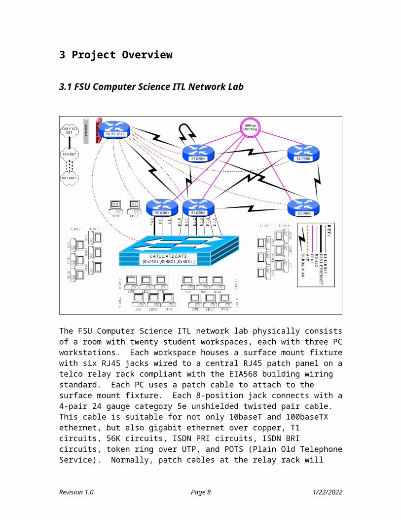
The FSU Computer Science ITL network lab physically consists of a room with twenty student workspaces, each with three PC workstations. Each workspace houses a surface mount fixture with six RJ45 jacks wired to a central RJ45 patch panel on a telco relay rack compliant with the EIA568 building wiring standard. Each PC uses a patch cable to attach to the surface mount fixture. Each 8-position jack connects with a 4-pair 24 gauge category 5e unshielded twisted pair cable. This cable is suitable for not only 10baseT and 100baseTX ethernet, but also gigabit ethernet over copper, T1 circuits, 56K circuits, ISDN PRI circuits, ISDN BRI circuits, token ring over UTP, and POTS (Plain Old Telephone Service). Normally, patch cables at the relay rack will connect the active connections to 10/100 ethernet ports on a pair of Cisco 3548XL layer 2 switches. Since only 3 of the 6 cables to each workspace will normally be in use, there is flexibility to add additional devices at the workspace to connect back to the central relay rack or to another workspace. The two Cisco 3548XL switches use an IEEE 802.1Q 1000baseSX gigabit ethernet trunk to connect to each other, and to a Cisco 3524XL switch at a remote location over multimode 62.5/125 fiber. The remote Cisco 3524XL switch connects to ethernet and fast ethernet ports on the lab routers. The VLAN capabilities of the layer-2 switches allow the student PC ethernet ports and router ethernet ports to be grouped into
Revision 1.0 Page 6 5/3/2023

VLANs with software reconfiguration. The core routers also have serial and FDDI interconnections between each other. A Cisco 2511 router provides firewalled access to the departmental network, network address translation, and out-of-band communication to the EIA RS-232-C console ports on lab devices.
3.2 Framework for Naming and Addressing
Many different naming addressing schemes are possible for a network lab environment, however, adopting some conventions as outlined below help eliminate confusion. These conventions also help keep a focus on the interesting aspects of networking with less time spent on the mechanics.
3.2.1 Device Names
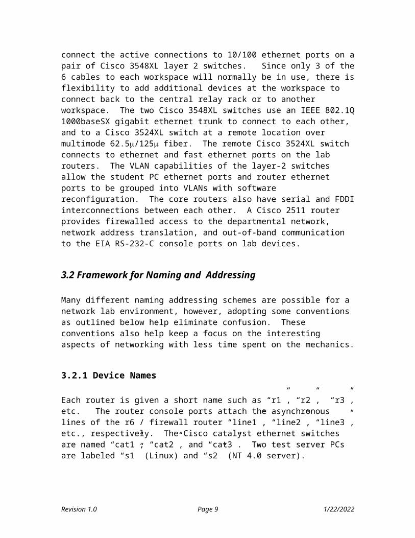
Each router is given a short name such as “r1”, “r2”, “r3”, etc. The router console ports attach the asynchronous lines of the r6 / firewall router “line1”, “line2”, “line3”, etc., respectively. The Cisco catalyst ethernet switches are named “cat1”, “cat2”, and “cat3”. Two test server PCs are labeled “s1” (Linux) and “s2” (NT 4.0 server).
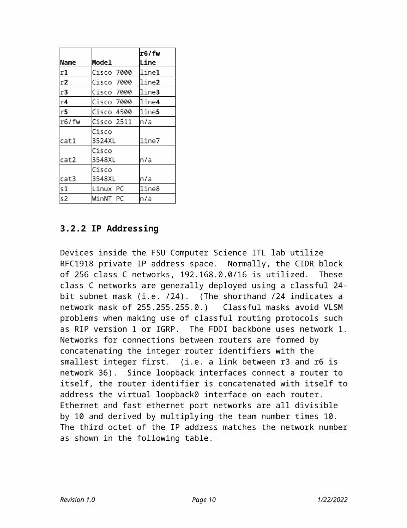
Name Model r6/fw Liner1 Cisco 7000 line1r2 Cisco 7000 line2r3 Cisco 7000 line3r4 Cisco 7000 line4r5 Cisco 4500 line5r6/fw Cisco 2511 n/acat1 Cisco 3524XL line7cat2 Cisco 3548XL n/acat3 Cisco 3548XL n/as1 Linux PC line8s2 WinNT PC n/a
3.2.2 IP Addressing
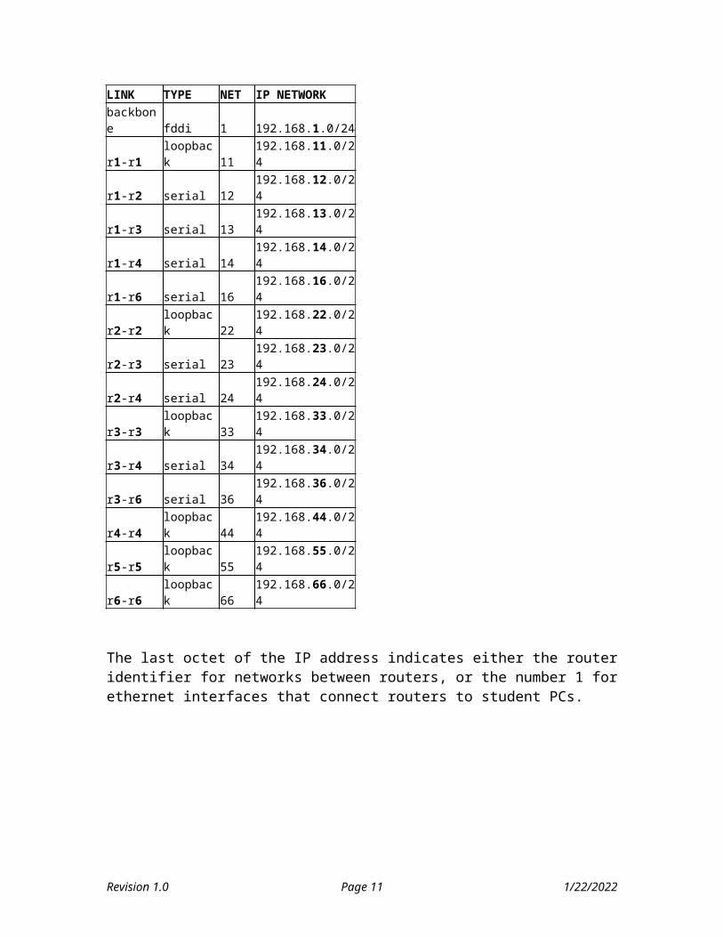
Devices inside the FSU Computer Science ITL lab utilize RFC1918 private IP address space. Normally, the CIDR block of 256 class C networks, 192.168.0.0/16 is utilized. These class C networks are generally deployed using a classful 24-bit subnet mask (i.e. /24). (The shorthand /24 indicates a network mask of 255.255.255.0.) Classful masks avoid VLSM problems when making use of classful routing protocols such as RIP version 1 or IGRP. The FDDI backbone uses network 1. Networks for connections between routers are formed by concatenating the integer router identifiers with the smallest integer first. (i.e. a link between r3 and r6 is network 36). Since loopback interfaces connect a router to itself, the router identifier is concatenated with itself to address the virtual loopback0 interface on each router. Ethernet and fast ethernet port
Revision 1.0 Page 7 5/3/2023
networks are all divisible by 10 and derived by multiplying the team number times 10. The third octet of the IP address matches the network number as shown in the following table.
LINK TYPE NET IP NETWORKbackbone fddi 1 192.168.1.0/24r1-r1 loopback 11 192.168.11.0/24r1-r2 serial 12 192.168.12.0/24r1-r3 serial 13 192.168.13.0/24r1-r4 serial 14 192.168.14.0/24r1-r6 serial 16 192.168.16.0/24r2-r2 loopback 22 192.168.22.0/24r2-r3 serial 23 192.168.23.0/24r2-r4 serial 24 192.168.24.0/24r3-r3 loopback 33 192.168.33.0/24r3-r4 serial 34 192.168.34.0/24r3-r6 serial 36 192.168.36.0/24r4-r4 loopback 44 192.168.44.0/24r5-r5 loopback 55 192.168.55.0/24r6-r6 loopback 66 192.168.66.0/24
The last octet of the IP address indicates either the router identifier for networks between routers, or the number 1 for ethernet interfaces that connect routers to student PCs.
Revision 1.0 Page 8 5/3/2023
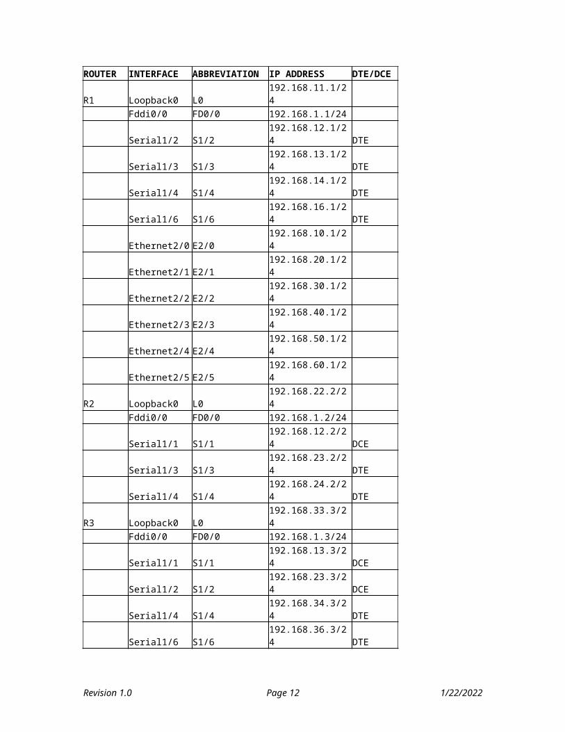
ROUTER INTERFACE ABBREVIATION IP ADDRESS DTE/DCER1 Loopback0 L0 192.168.11.1/24
Fddi0/0 FD0/0 192.168.1.1/24Serial1/2 S1/2 192.168.12.1/24 DTESerial1/3 S1/3 192.168.13.1/24 DTESerial1/4 S1/4 192.168.14.1/24 DTESerial1/6 S1/6 192.168.16.1/24 DTEEthernet2/0 E2/0 192.168.10.1/24Ethernet2/1 E2/1 192.168.20.1/24Ethernet2/2 E2/2 192.168.30.1/24Ethernet2/3 E2/3 192.168.40.1/24Ethernet2/4 E2/4 192.168.50.1/24Ethernet2/5 E2/5 192.168.60.1/24
R2 Loopback0 L0 192.168.22.2/24Fddi0/0 FD0/0 192.168.1.2/24Serial1/1 S1/1 192.168.12.2/24 DCESerial1/3 S1/3 192.168.23.2/24 DTESerial1/4 S1/4 192.168.24.2/24 DTE
R3 Loopback0 L0 192.168.33.3/24Fddi0/0 FD0/0 192.168.1.3/24Serial1/1 S1/1 192.168.13.3/24 DCESerial1/2 S1/2 192.168.23.3/24 DCESerial1/4 S1/4 192.168.34.3/24 DTESerial1/6 S1/6 192.168.36.3/24 DTE
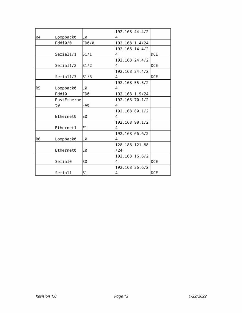
R4 Loopback0 L0 192.168.44.4/24Fddi0/0 FD0/0 192.168.1.4/24Serial1/1 S1/1 192.168.14.4/24 DCESerial1/2 S1/2 192.168.24.4/24 DCESerial1/3 S1/3 192.168.34.4/24 DCE
R5 Loopback0 L0 192.168.55.5/24Fddi0 FD0 192.168.1.5/24FastEthernet0 FA0 192.168.70.1/24Ethernet0 E0 192.168.80.1/24Ethernet1 E1 192.168.90.1/24
R6 Loopback0 L0 192.168.66.6/24Ethernet0 E0 128.186.121.88/24Serial0 S0 192.168.16.6/24 DCESerial1 S1 192.168.36.6/24 DCE
Revision 1.0 Page 9 5/3/2023
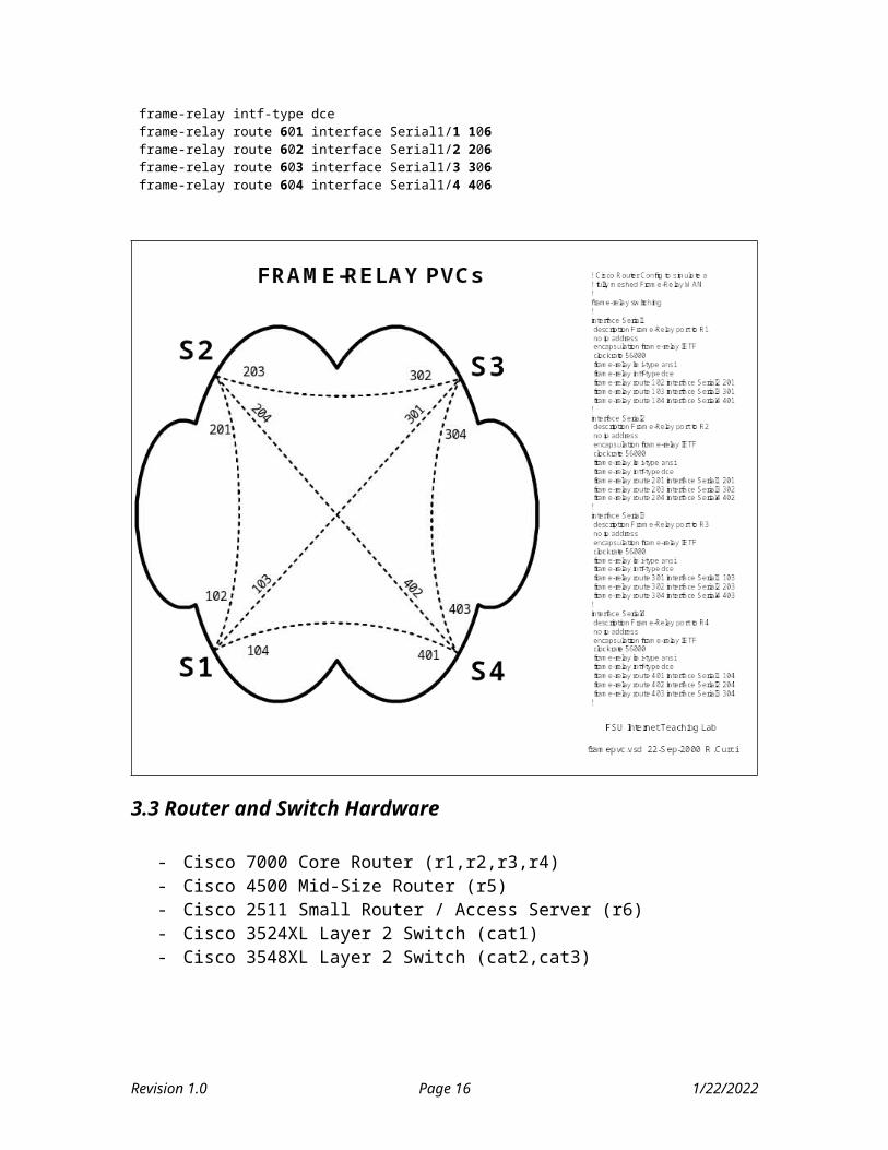
3.2.3 Frame-Relay PVC DLCI Labels
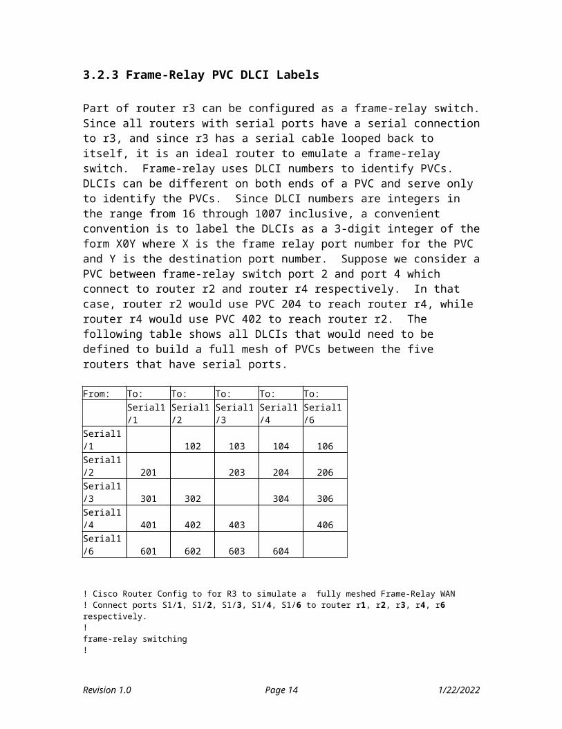
Part of router r3 can be configured as a frame-relay switch. Since all routers with serial ports have a serial connection to r3, and since r3 has a serial cable looped back to itself, it is an ideal router to emulate a frame-relay switch. Frame-relay uses DLCI numbers to identify PVCs. DLCIs can be different on both ends of a PVC and serve only to identify the PVCs. Since DLCI numbers are integers in the range from 16 through 1007 inclusive, a convenient convention is to label the DLCIs as a 3-digit integer of the form X0Y where X is the frame relay port number for the PVC and Y is the destination port number. Suppose we consider a PVC between frame-relay switch port 2 and port 4 which connect to router r2 and router r4 respectively. In that case, router r2 would use PVC 204 to reach router r4, while router r4 would use PVC 402 to reach router r2. The following table shows all DLCIs that would need to be defined to build a full mesh of PVCs between the five routers that have serial ports.
From: To: To: To: To: To:Serial1/1 Serial1/2 Serial1/3 Serial1/4 Serial1/6
Serial1/1 102 103 104 106Serial1/2 201 203 204 206Serial1/3 301 302 304 306Serial1/4 401 402 403 406Serial1/6 601 602 603 604
! Cisco Router Config to for R3 to simulate a fully meshed Frame-Relay WAN! Connect ports S1/1, S1/2, S1/3, S1/4, S1/6 to router r1, r2, r3, r4, r6 respectively.!frame-relay switching!interface Serial1/1 description Frame-Relay port to R1 no ip address encapsulation frame-relay IETF clockrate 2000000 frame-relay lmi-type ansi frame-relay intf-type dce frame-relay route 102 interface Serial1/2 201 frame-relay route 103 interface Serial1/3 301 frame-relay route 104 interface Serial1/4 401 frame-relay route 106 interface Serial1/6 601!interface Serial1/2 description Frame-Relay port to R2 no ip address encapsulation frame-relay IETF clockrate 2000000 frame-relay lmi-type ansi frame-relay intf-type dce frame-relay route 201 interface Serial1/1 102 frame-relay route 203 interface Serial1/3 302 frame-relay route 204 interface Serial1/4 402 frame-relay route 206 interface Serial1/6 602!interface Serial1/3
Revision 1.0 Page 10 5/3/2023
description Frame-Relay port to R3 no ip address encapsulation frame-relay IETF clockrate 2000000 frame-relay lmi-type ansi frame-relay intf-type dce frame-relay route 301 interface Serial1/1 103 frame-relay route 302 interface Serial1/2 203 frame-relay route 304 interface Serial1/4 403 frame-relay route 306 interface Serial1/6 603!interface Serial1/4 description Frame-Relay port to R4 no ip address encapsulation frame-relay IETF frame-relay lmi-type ansi frame-relay intf-type dce frame-relay route 401 interface Serial1/1 104 frame-relay route 402 interface Serial1/2 204 frame-relay route 403 interface Serial1/3 304 frame-relay route 406 interface Serial1/6 604!interface Serial1/6 description Frame-Relay port to R6 no ip address encapsulation frame-relay IETF frame-relay lmi-type ansi frame-relay intf-type dce frame-relay route 601 interface Serial1/1 106 frame-relay route 602 interface Serial1/2 206 frame-relay route 603 interface Serial1/3 306 frame-relay route 604 interface Serial1/4 406
Revision 1.0 Page 11 5/3/2023
3.3 Router and Switch Hardware
- Cisco 7000 Core Router (r1,r2,r3,r4)- Cisco 4500 Mid-Size Router (r5)- Cisco 2511 Small Router / Access Server (r6)- Cisco 3524XL Layer 2 Switch (cat1)- Cisco 3548XL Layer 2 Switch (cat2,cat3)
The Cisco 7000 routers are large systems once deployed on the MCI Internet backbone. They have both FDDI and serial interface cards. One additionally has a 6-port ethernet card. The Cisco 4500 has a FDDI port, two ethernet ports, and a fast ethernet port. The 7000 and 4500 routers are programmed by the students in these labs. The Cisco 2511 router provides two serial ports, an ethernet port, and 16 asynchronous ports. It provides both firewall functionality and out-of-band access to other lab devices through their console ports. The Cisco 3524XL and 3548XL switches provide connectivity between the router ethernet ports and student PC ethernet ports. They also tie together the router equipment with the network lab through a gigabit ethernet trunk. This allows for the router equipment and student PCs to be located in different rooms to reduce the ambient
Revision 1.0 Page 12 5/3/2023
noise level in the student network lab and provide a higher level of physical security for the router equipment. See the Appendix A for more detailed information.
4 FSU Computer Science ITL Implementation
4.1 Out-of-band Communications
It is important in a network lab environment to be able to configure the environment quickly. Because changes typically include modifying the addressing scheme, changing the routing protocols, or even erasing the configuration, it is not always possible to use the TCP/IP protocol to remotely access the router and switch devices directly. All router and switch devices in the ITL lab have RS232 console ports that can be used to configure the devices using a directly connected dumb terminal or terminal emulator. This approach solves the problem of configuring the network devices but requires physically moving the console cable from one device to the next for access. Moving cables is possible when the operator is near the equipment but inconvenient or impossible when distance separates the user from the router equipment. A router feature called “reverse telnet” on the Cisco 2511 router/access server solves this problem. A user can log into the firewall 2511 router and type an alias such as “r1”, “r2”, etc., to connect to the corresponding router console port. Since the 2511 router has 16 async RS232 ports, it is possible to leave one async port permanently attached to each router and switch console port. For example, when an instructor wants to reconfigure the setup on all five student routers, each router can be erased, rebooted, and reprogrammed in a matter of minutes. With the appropriate passwords, this reconfiguration can even be performed remotely.
4.2 Firewall
Router r6 doubles as a firewall. It has a permanent ethernet connection to the FSU Computer Science network and serves as the gateway between the ITL lab network and the outside. Since this is the only lab device connecting to the outside network, it provides a convenient single “choke point.” Access lists on this router’s ethernet port are used to help secure the lab by controlling what traffic is permitted to flow between the lab and outside networks. In general, the firewall limits access from outside into the lab network, but allows the lab network devices to access the outside. Since many assignments in the networking lab call for students to access the web to download files, this is very convenient. During times when more dangerous assignments are assigned, these access lists can be adapted to be more restrictive. For example, when security network probe tools like NMAP are explored, it may be prudent to prevent lab devices from accessing systems outside the Computer Science Department. The two serial ports on this router normally provide two 2Mbit/sec links to routers r1 and r3. See the appendix for a sample configuration of this router.
4.3 Network Address Translation (NAT)
Revision 1.0 Page 13 5/3/2023
Router r6 contains runs Cisco IOS v12.0 software which contains a Network Address Translation feature. The ethernet on router r6 is tagged as “outside” while all other interfaces are “inside.” When an IP packet is routed between an outside and inside interface, network address translation takes place. Normally, all devices inside the lab are configured with RFC1918 private IP address space. When a lab device attempts to reach a device outside the lab, the packet follows the default route to r6 where an unused port number is selected and the packet sent out the ethernet port. To devices outside the lab, router r6 appears as if it is a multiuser computer system. Response packets are translated in the opposite direction. Since lab devices only have private addresses, they are generally protected from the Internet, yet have access to the Internet. The command “show ip nat translation” can be used to see a snapshot of the current global and local address and port mappings. Normally, these mappings occur dynamically and overload the r6 ethernet port IP address by multiplexing using unused 16-bit port numbers. It is also possible to statically map an IP address. For example, in the course of this project, it has been handy to be able to access Linux server S1 and NT server S2. Inside the lab network, S1 and S2 have IP addresses 192.168.10.2/24 and 192.168.10.3/24 respectively. By statically mapping these local IP addresses to global addresses 128.186.121.89 and 128.186.121.90, and further defining the names itl2.cs.fsu.edu and itl3.cs.fsu.edu, these servers can be reached from outside using the fully qualified domain name.
4.4 Flexible Interconnections
Flexibility in how the lab network devices are interconnected improves the lab versatility. It is especially desirable to have the capability of reconfiguring the network connections without the need to physically move cables. Moving cables requires physical access and is inconvenient when the user is located remotely and is also prone to hardware problems such as bending cable connector pins or fouling fiber optic connectors. Flexibility in how routers are connected without the need for manual cable moves is achieved with three techniques:
1. Layer 2 Ethernet Switch VLANs2. Physical Serial Cable Mesh3. Frame-Relay WAN Emulation4. GRE Tunnels
4.4.1 Layer 2 Ethernet Switch VLANs
Modern layer 2 ethernet switches such as the Cisco Catalyst 3524XL and 3548XL have the capability of implementing Virtual Local Area Networks (VLANs) and trunking. Most layer 2 ethernet switches default to logically acting as a multiport bridge where all ports are part of the same layer 2 network. VLANs allow the ports to be grouped, or colored, and segregated into different virtual LANs. Additionally, trunking protocols like IEEE 802.1Q and ISL (Inter Switch Link) allow single physical connections between switches to carry multiple VLANs by prepending data link frames with a header indicating the VLAN. In effect, trunking allows a set of interconnected switches to
Revision 1.0 Page 14 5/3/2023

logically act as a single large switch even when the switches are in different locations. For example, the student routers have a total of nine ethernet and fast ethernet ports that can each be assigned a different VLAN. The student lab PCs can then be logically connected to any router ethernet or fast ethernet port by assigning their ports to the appropriate matching VLAN. This technique allows the set of router ethernet ports and lab PC ethernet ports to be logically grouped in any combination of mutually exclusive subsets.
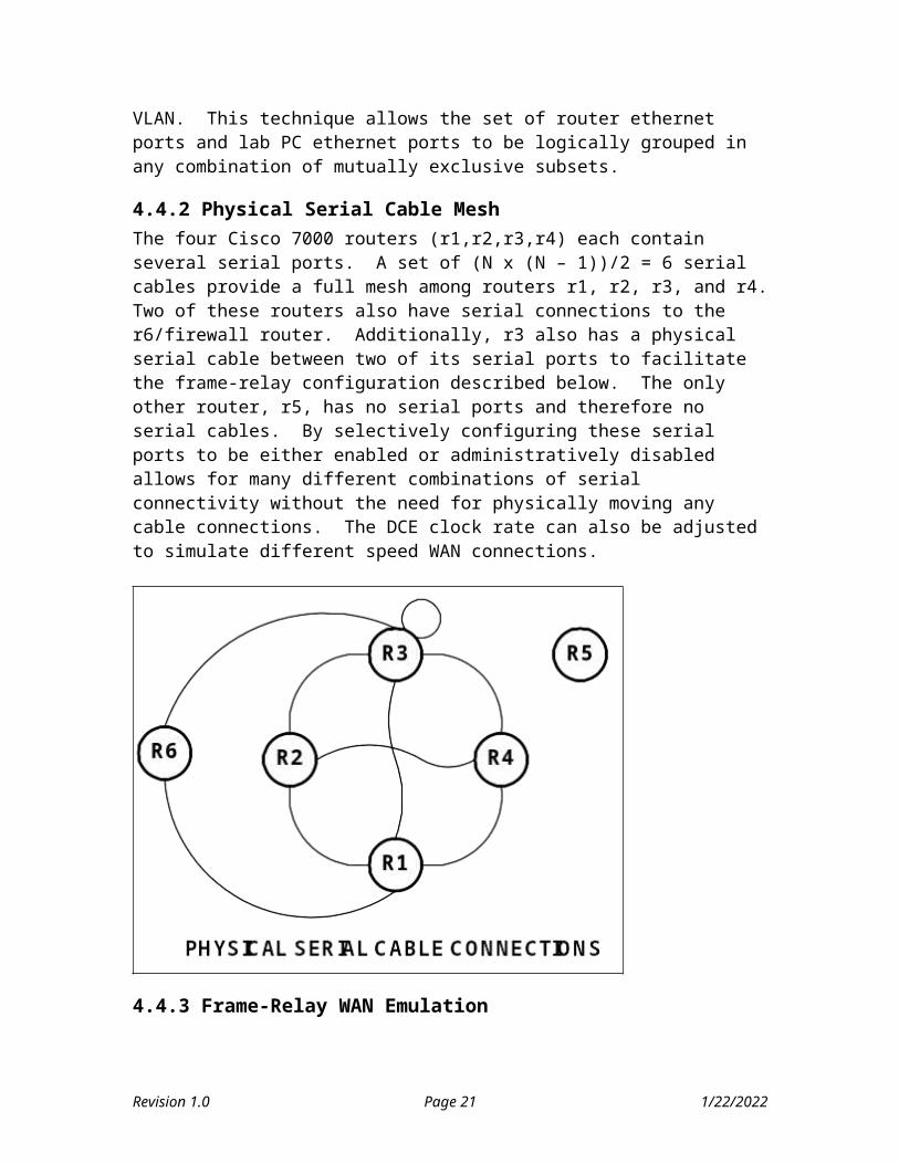
4.4.2 Physical Serial Cable MeshThe four Cisco 7000 routers (r1,r2,r3,r4) each contain several serial ports. A set of (N x (N – 1))/2 = 6 serial cables provide a full mesh among routers r1, r2, r3, and r4. Two of these routers also have serial connections to the r6/firewall router. Additionally, r3 also has a physical serial cable between two of its serial ports to facilitate the frame-relay configuration described below. The only other router, r5, has no serial ports and therefore no serial cables. By selectively configuring these serial ports to be either enabled or administratively disabled allows for many different combinations of serial connectivity without the need for physically moving any cable connections. The DCE clock rate can also be adjusted to simulate different speed WAN connections.
4.4.3 Frame-Relay WAN Emulation
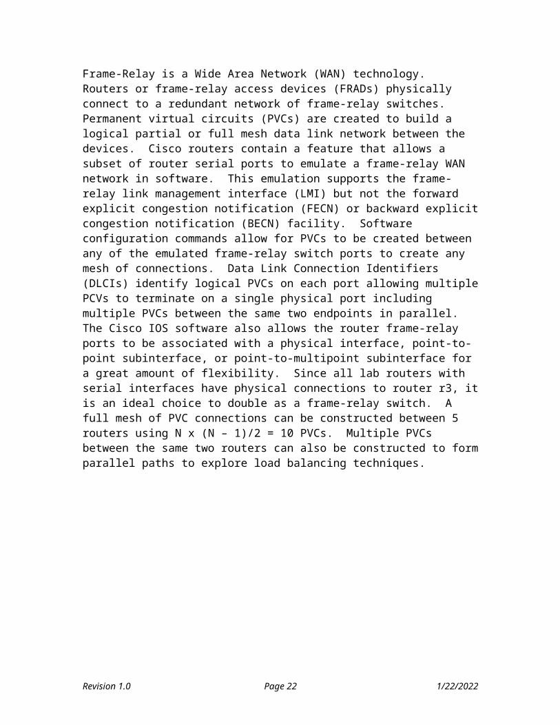
Frame-Relay is a Wide Area Network (WAN) technology. Routers or frame-relay access devices (FRADs) physically connect to a redundant network of frame-relay switches. Permanent virtual circuits (PVCs) are created to build a logical partial or full mesh data link network between the devices. Cisco routers contain a feature that allows a subset of router serial ports to emulate a frame-relay WAN network in software. This emulation
Revision 1.0 Page 15 5/3/2023
supports the frame-relay link management interface (LMI) but not the forward explicit congestion notification (FECN) or backward explicit congestion notification (BECN) facility. Software configuration commands allow for PVCs to be created between any of the emulated frame-relay switch ports to create any mesh of connections. Data Link Connection Identifiers (DLCIs) identify logical PVCs on each port allowing multiple PCVs to terminate on a single physical port including multiple PVCs between the same two endpoints in parallel. The Cisco IOS software also allows the router frame-relay ports to be associated with a physical interface, point-to-point subinterface, or point-to-multipoint subinterface for a great amount of flexibility. Since all lab routers with serial interfaces have physical connections to router r3, it is an ideal choice to double as a frame-relay switch. A full mesh of PVC connections can be constructed between 5 routers using N x (N – 1)/2 = 10 PVCs. Multiple PVCs between the same two routers can also be constructed to form parallel paths to explore load balancing techniques.
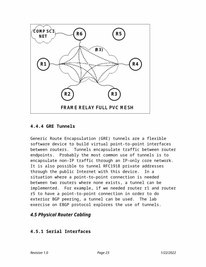
4.4.4 GRE Tunnels
Generic Route Encapsulation (GRE) tunnels are a flexible software device to build virtual point-to-point interfaces between routers. Tunnels encapsulate traffic between router endpoints. Probably the most common use of tunnels is to encapsulate non-IP traffic through an IP-only core network. It is also possible to tunnel RFC1918 private addresses through the public Internet with this device. In a situation where a point-to-point connection is needed between two routers where none exists, a tunnel can be implemented. For example, if we needed router r1 and router r5 to have a point-to-point connection in order to do exterior BGP peering, a tunnel can be used. The lab exercise on EBGP protocol explores the use of tunnels.
Revision 1.0 Page 16 5/3/2023

4.5 Physical Router Cabling
4.5.1 Serial Interfaces
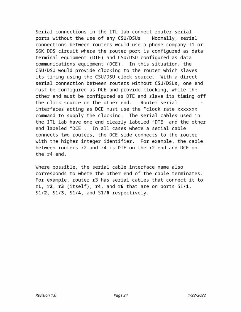
Serial connections in the ITL lab connect router serial ports without the use of any CSU/DSUs. Normally, serial connections between routers would use a phone company T1 or 56K DDS circuit where the router port is configured as data terminal equipment (DTE) and CSU/DSU configured as data communications equipment (DCE). In this situation, the CSU/DSU would provide clocking to the router which slaves its timing using the CSU/DSU clock source. With a direct serial connection between routers without CSU/DSUs, one end must be configured as DCE and provide clocking, while the other end must be configured as DTE and slave its timing off the clock source on the other end. Router serial interfaces acting as DCE must use the “clock rate xxxxxxx” command to supply the clocking. The serial cables used in the ITL lab have one end clearly labeled “DTE” and the other end labeled “DCE”. In all cases where a serial cable connects two routers, the DCE side connects to the router with the higher integer identifier. For example, the cable between routers r2 and r4 is DTE on the r2 end and DCE on the r4 end.
Where possible, the serial cable interface name also corresponds to where the other end of the cable terminates. For example, router r3 has serial cables that connect it to r1, r2, r3 (itself), r4, and r6 that are on ports S1/1, S1/2, S1/3, S1/4, and S1/6 respectively.
4.5.2 FDDI Interfaces
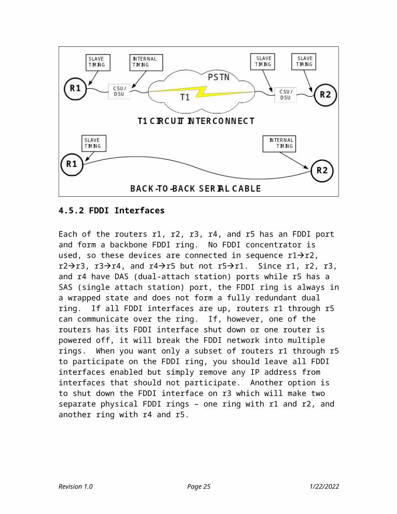
Each of the routers r1, r2, r3, r4, and r5 has an FDDI port and form a backbone FDDI ring. No FDDI concentrator is used, so these devices are connected in sequence r1r2,
Revision 1.0 Page 17 5/3/2023
r2r3, r3r4, and r4r5 but not r5r1. Since r1, r2, r3, and r4 have DAS (dual-attach station) ports while r5 has a SAS (single attach station) port, the FDDI ring is always in a wrapped state and does not form a fully redundant dual ring. If all FDDI interfaces are up, routers r1 through r5 can communicate over the ring. If, however, one of the routers has its FDDI interface shut down or one router is powered off, it will break the FDDI network into multiple rings. When you want only a subset of routers r1 through r5 to participate on the FDDI ring, you should leave all FDDI interfaces enabled but simply remove any IP address from interfaces that should not participate. Another option is to shut down the FDDI interface on r3 which will make two separate physical FDDI rings – one ring with r1 and r2, and another ring with r4 and r5.
4.5.3 Ethernet and Fast Ethernet Interfaces
Router r1 has six ethernet interfaces while router r5 has one fast ethernet and two ethernet interfaces. These nine interfaces connect to the Cisco Catalyst 3524XL on ports FastEthernet0/1 through FastEthernet0/9 using standard RJ45 category 5 patch cables. Since the r1 ports use DB15 AUI connectors, Allied Telesyn 210TS tranceivers adapt these ports to the 10baseT standard. R5 has both 10baseT and AUI ports on its ethernet interfaces, and 100baseTX and MII ports on its fast ethernet interface. Because r5 contains RJ45 connections, tranceivers are unnecessary but care must be taken to active the correct physical connector with the interface “media-type” command. By default, the switch ports are configured to auto sense the port speed and duplex settings. Normally, these nine ports are each placed in different VLANs as indicated in the table below.
Revision 1.0 Page 18 5/3/2023

Router Router Interface Cat3524XL VLANr1 Ethernet2/0 FastEthernet0/1 10
Ethernet2/1 FastEthernet0/2 20Ethernet2/2 FastEthernet0/3 30Ethernet2/3 FastEthernet0/4 40Ethernet2/4 FastEthernet0/5 50Ethernet2/5 FastEthernet0/6 60
r5 FastEthernet0 FastEthernet0/9 70Ethernet0 FastEthernet0/10 80Ethernet1 FastEthernet0/11 90
4.6 Guidelines for Creating Labs
4.6.1 Loopback Interfaces
Loopback interfaces are virtual router interfaces that can be created on demand which never fail. When a router is connected to a network through multiple physical connections, it is possible for a physical interface to go down while the router remains connected to the network. If a communication session such as a tunnel, ntp, telnet, bgp peering session, etc., is referencing the down interface, it will fail. For this reason, loopback interfaces are often created and an IP address assigned that is used to reference the router which will remain up as long as the router has some connectivity and an appropriate routing protocol.
Revision 1.0 Page 19 5/3/2023
In the FSU Computer Science ITL lab environment, loopback interfaces are also useful. No matter what model Cisco IOS router and IOS software is available, many loopback interfaces can be created to make more complex and interesting lab exercises. For example, in the VLSM lab, each router has 4 loopback addresses named loopback0, loopback1, loopback2, and loopback3 each with different addresses and network mask. One aspect of this lab is the focus on using OSPF’s ability to summarize a group of directly connected networks into a single aggregate routing advertisement. Another example is the RIP lab where some routers that have no physical ethernet ports use a loopback interface as a substitute. Although not functional like an ethernet interface, a loopback interface is treated almost the same in Cisco IOS and is ideal for experimenting with routing protocols.
4.6.2 Team Challenges
In practice, building and troubleshooting data networks requires a lot of teamwork. For example, if you are configuring a router for your organization, it will often need to communicate or connect to a router in a different organization where you are unlikely to have access. For this reason, it becomes important to clearly define the point of demarcation, IP addressing schemes, routing protocols, announcements of routes, OSPF area numbers, BGP autonomous system numbers, etc. Many of the sample labs include a detailed blueprint -- a detailed network diagram, information on the IP addressing scheme and routing protocols. If each team closely follows the instructions, the network will interoperate. It is also helpful to expose students to the process of working with the entire class of students to define the blueprint for the network. For example, the sample VLSM lab requires the entire class of students to first define a blueprint that defines the IP addressing and subnetting scheme before it can be implemented. This type of exposure is helpful to prepare students for team challenges they will face outside of school.
4.6.3 Hints and Tools
Many of the sample labs try to give students hints and tools rather than answers to questions. Helping students learn where to seek information will help with future challenges. Some hints suggest that the student read the manual section that describes a particular Cisco IOS configuration, show, or debug command. Understanding how to utilize tools and utilities such as IP PING, IP TRACEROUTE, IPX PING, Appletalk PING, and TTCP are helpful for debugging and isolating problems. Less frequently used options like extended IP PING or extended IP TRACEROUTE are also handy tools. With an understanding of how the various network protocols function, even a simple tool like TELNET can be used to connect to services such as WWW, SMTP, and POP3 for testing. When testing access lists, the /SOURCE-INTERFACE option inside the Cisco IOS TELNET can change the source IP address of the session which can be enormously helpful for debugging. The use of DEBUG mode and SYSLOG to send debug messages
Revision 1.0 Page 20 5/3/2023
to a UNIX host where the many messages can be post-processed is also a powerful tool. Many of these tools are explored in the sample lab exercises.
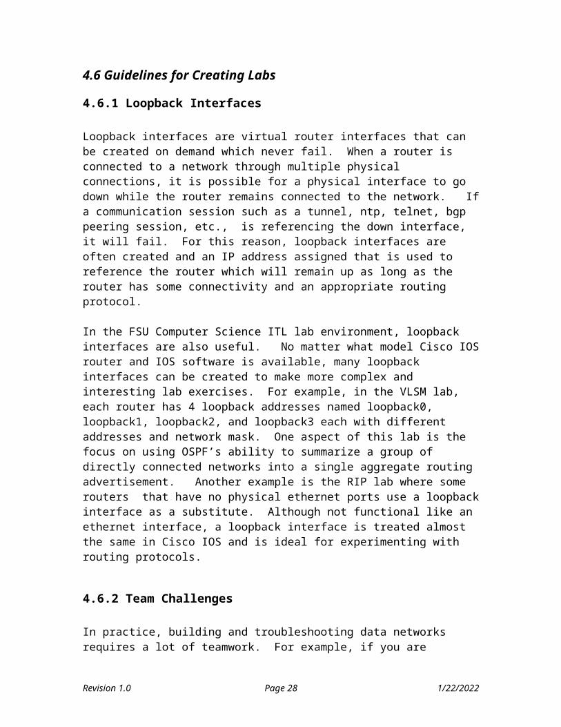
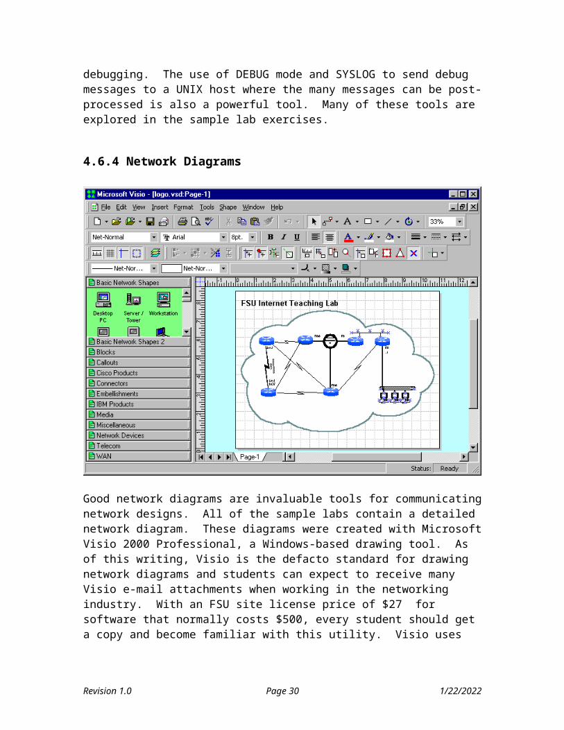
4.6.4 Network Diagrams
Good network diagrams are invaluable tools for communicating network designs. All of the sample labs contain a detailed network diagram. These diagrams were created with Microsoft Visio 2000 Professional, a Windows-based drawing tool. As of this writing, Visio is the defacto standard for drawing network diagrams and students can expect to receive many Visio e-mail attachments when working in the networking industry. With an FSU site license price of $27 for software that normally costs $500, every student should get a copy and become familiar with this utility. Visio uses “stencils”9 of graphic elements and connectors to speed the drawing process. Many graphics representing networking and computer components are included with the package. In preparing the sample labs, additional stencils downloaded from Cisco Systems were also used. Copies of these stencils are included in two ZIP archive files on the project CD-ROM.
9 These are similar to AutoCAD component libraries.
Revision 1.0 Page 21 5/3/2023
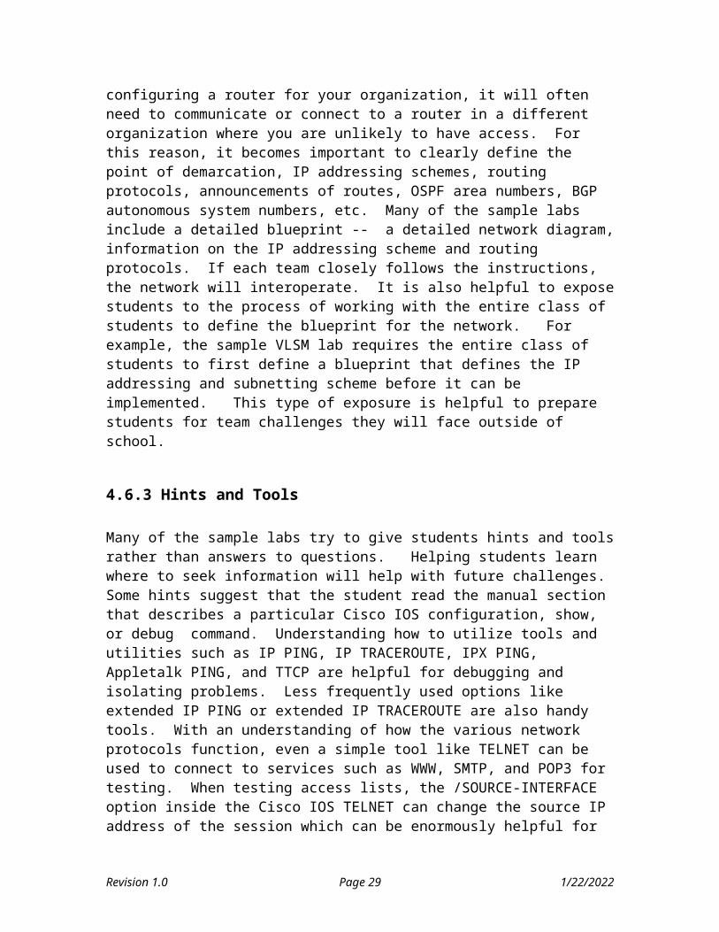
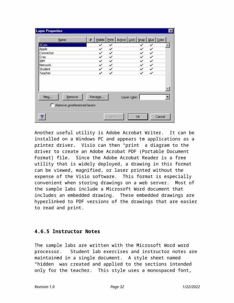
Another useful feature of Visio is its layering ability. Individual items can be assigned to different layers. Each layer can then be selected to be visible or printed. Some of the drawings for the sample labs have several common layers plus a “student” and “teacher” layer. For example, in the sample Topology Discovery Lab, the drawing can be printed with the student layer turned on and teacher layer turned off for the student, and printed with the settings reversed for the teacher. For many drawings, most of the work in their creation is in the components in the common layers. Maintaining a single drawing with two layers to be toggled on and off is much easier than maintaining separate drawings.
Revision 1.0 Page 22 5/3/2023
Another useful utility is Adobe Acrobat Writer. It can be installed on a Windows PC and appears to applications as a printer driver. Visio can then “print” a diagram to the driver to create an Adobe Acrobat PDF (Portable Document Format) file. Since the Adobe Acrobat Reader is a free utility that is widely deployed, a drawing in this format can be viewed, magnified, or laser printed without the expense of the Visio software. This format is especially convenient when storing drawings on a web server. Most of the sample labs include a Microsoft Word document that includes an embedded drawing. These embedded drawings are hyperlinked to PDF versions of the drawings that are easier to read and print.
4.6.5 Instructor Notes
The sample labs are written with the Microsoft Word word processor. Student lab exercises and instructor notes are maintained in a single document. A style sheet named “hidden” was created and applied to the sections intended only for the teacher. This style uses a monospaced font, hidden attribute, and a 4 ½ point red border on the right. This allows for printing both a student and teacher version of the lab by selecting whether to print the hidden text. When the hidden text enabled, the teacher notes appear interspersed and can be easily identified by the thick border on the right.
The instructor notes include answers, comments on common pitfalls, sample solutions, additional tables and diagrams, sample command output, etc.
It is much easier to maintain a single lab document file with both student and teacher components than separate documents.
4.7 Sample Lab Exercises
Several sample lab exercises have been written. There are three different types of sample labs.
1. Generic Labsa. Cisco Router Basics (inverse telnet, modes, etc.)b. Cisco Router Debugging (show commands, debug mode)
2. CIS5406 (Computer Network and System Admin) Labsa. Topology Discovery Lab (RIP,SNMP,IPERF,TROUTE)b. Start-From-Scratch Lab (RIP)c. Multiprotocol Lab (IPX, Appletalk)d. Routing Information Protocol Lab (RIP)e. IGP Lab (RIP,OSPF,IGRP,EIGRP,ISIS)f. ACL Lab (access lists, NTP, SYSLOG)g. Frame-Relay Lab (Frame-Relay emulation, RIP, Split-Horizon)
Revision 1.0 Page 23 5/3/2023
h. BGP Lab (Exterior BGP protocol, tunnels)i. VLSM Lab (variable length subnetting, OSPF)
3. CEN5515 (Data and Computer Communications) Labsa. Spanning Tree Lab (802.1D)b. Count-To-Infinity / Split Horizon Lab (RIP)
The generic labs include exercises to help students become familiar with the mechanics of the Cisco routers. This includes topics like how to log into a router, how to use reverse telnet to access a router console port, regular and enabled modes, configuration mode, etc. It also includes information on common “show” and “debug” commands for isolating and resolving network problems.
The CIS5406 labs are intended to be used as a hands-on lab component of this graduate Computer Network and Systems Administration class. They explore tools to measure network performance, routing management tools, routing protocols, subnetting, access lists, non-IP protocols, etc.
The CEN5515 labs are intended to explore data communications algorithms such as the 802.1D spanning tree protocol, distance vector routing protocols, and link state routing protocols.
Each lab contains a Microsoft Word writeup containing diagrams and exercises. The writeups also contain hidden text for instructors to point out common pitfalls, sample solutions, hints, and examples. By incorporating both components in each document, it can be printed in both a student and teacher version by disabling or enabling the hidden text. Each student version of the writeup is also available in hypertext format for easy web browser access. The hypertext version also has a hyperlink to a detailed network diagram in Adobe portable document format allowing easy printing of high resolution laser copies of the diagrams. All drawings were created in Microsoft Visio 2000 but also available in PDF format. The accompanying CD-ROM includes many other files related to the labs that include sample router configurations, captures of various show commands, routing tables, etc. Many also include additional information in Microsoft Excel spreadsheet format.
5 Conclusion
5.1 ITL as an Inexpensive Learning Tool
Computer networks and computer system administration have become increasingly important topics with the recent proliferation of computer networks, multiuser computer systems, and the Internet. Demand in the job market for professionals to build and maintain these systems continues to grow. Employers are seeking professionals with the right combination of theoretical background, problem solving skills, and practical
Revision 1.0 Page 24 5/3/2023
experience. Unfortunately, many Computer Science degree programs ignore the practical topics of the industry and focus solely on the theoretical aspects. This is a very similar paradigm to the situation 10 years ago when many students graduating with Computer Science degrees had experience with mainframe computers but little or no exposure to microcomputers. The Florida State University Department of Computer Science has been a leader in this area and has developed the Computer Networking and Systems Administration Masters Track to help prepare students for this important profession.
The FSU Internet Teaching Lab utilizes mostly older networking equipment that has been removed from production networks. Many of the donated items such as the Cisco 7000 routers once deployed on the MCI Internet backbone have been replaced with newer models. Although this equipment is unsupported and will not run the latest IOS software and somewhat obsolete, there is plenty of functionality to be useful as a learning tool. This gives universities like FSU equipment at little or no cost that can be used to help teach students. The students, in turn, will graduate with better practical networking experience and be more desirable as prospective employees of the high tech companies including those who have donated equipment.
Obviously, the goal of a program like the CNSA track should not be to train network technicians who only understand practical aspects with no theoretical background. A better approach is to educate professionals with a broad range of skills and knowledge and in both theoretical and practical areas of this industry who have the ability to learn, grow, and adapt as the computer networking industry changes. The ability to solve problems, grow, and adapt is critical in such a rapidly changing industry.
5.2 Future Directions
There are many topics that could not be explored in this Internet Teaching Lab due to a lack of equipment. Some topics could not be explored because many of the routers only support older IOS software and lack some of the newer features. Still other topics can be explored with the existing lab equipment but were not developed due to project time constraints.
- ISDNWith additional router ISDN PRI and/or BRI ports and an ISDN emulator, it would be possible to explore lab experiments that implement dial on demand routing (DDR). This feature allows for routers to establish backup dial connections upon detecting a failure in the network.
- VoIP / TelephonyVoice over IP is a hot topic. IP telephones and programs like Microsoft NetMeeting can be used to establish voice calls over an IP data network. ISDN PRI, ISDN BRI, FXO, and FXS interfaces are available on routers to experiment with these protocols. With the proper hardware and software, for example, a
Revision 1.0 Page 25 5/3/2023

router can be connected to a telephone or ISDN line and configured as an H.323 gateway and accessed from a remote IP telephone or PC running NetMeeting. These experiments would require additional hardware and some phone lines, ISDN lines, or simulator.
- ATMAsynchronous Transfer Mode is an important topic in wide area networks. Lab experimenting would require some rather expensive router ATM interface cards and an ATM switch. Many topics could be covered such as PVCs, SVCs, classical IP over ATM, and LANE.
- QoSQuality of service is an important topic in modern networks. Use of the IP type of service (TOS) bits to classify traffic and implement different queuing strategies could be explored. These issues are becoming more important with the high cost of Internet bandwidth and the mixing of voice, video, and data traffic that place different demands on a network. For example, video and audio are very sensitive to jitter and insensitive to some packet loss, while data is usually unaffected by jitter but packet loss is intolerable. Newer router hardware that supports newer IOS software has many QoS features.
- IPSEC / VPNs / MPLSIPSEC tunneling, virtual private networks, and multiprotocol label switching can also be explored. These techniques are used to build virtual private networks across public Internetworks and are very important topics. Access to these features again is restricted to newer routers that can run the latest IOS software.
- IP MulticastIP Multicast is an important feature to distribute datastreams to multiple receipients. Protocols such as PIM, DVRMP, IGMP, and CGMP are supported in recent IOS software images. These topics can be explored without additional lab equipment.
- HSRPThe hot standby routing protocol enables two routers on a LAN segment to work together to provide a reliable virtual router. This is handy for hosts that do not understand routing protocols configured with a static default route pointing at the highly available virtual router. No additional lab hardware is required to experiment with this protocol.
- ISL TrunkingAn important topic is to be able to use router in a “one armed router” or “router on a stick” configuration. A single router port capable of ISL trunking such as the fast ethernet port on r5 is connected to a switch and programmed to trunk. Many subinterfaces on the router can be created which can expand the number of logical ethernet ports on the router. Each physical port on the switch can be logically
Revision 1.0 Page 26 5/3/2023

configured as a separate router interface on a different network. No additional lab equipment is required to experiment with this protocol, although only the single fast ethernet interface is capable of this feature.
Revision 1.0 Page 27 5/3/2023
Appendices
Appendix A: Router Hardware Overview
Cisco 7000 Core Router
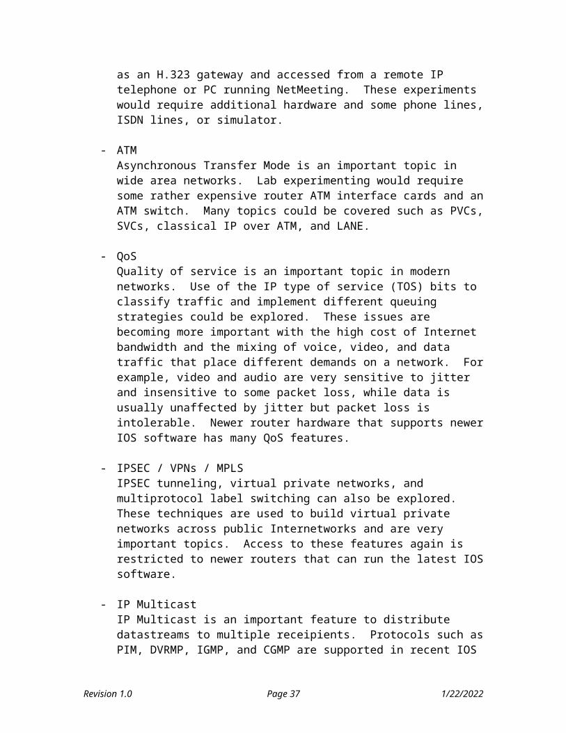
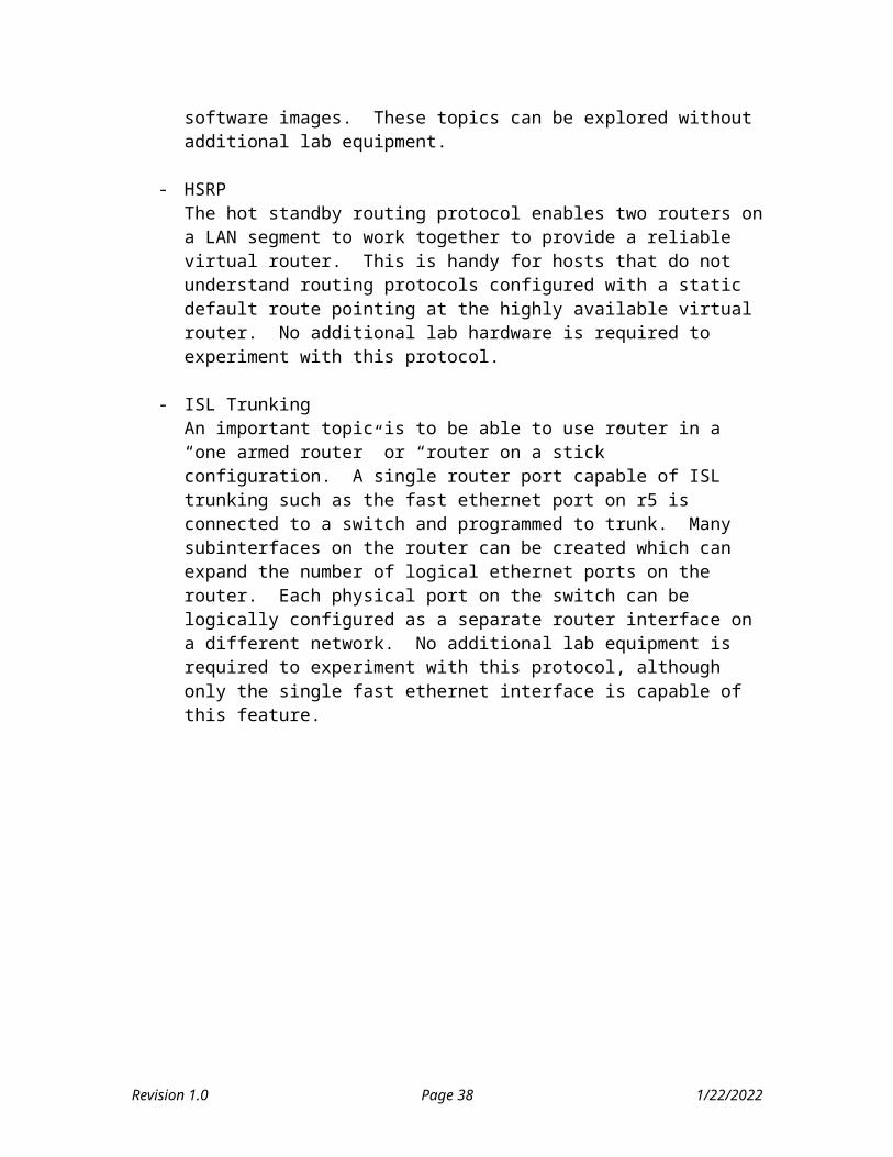
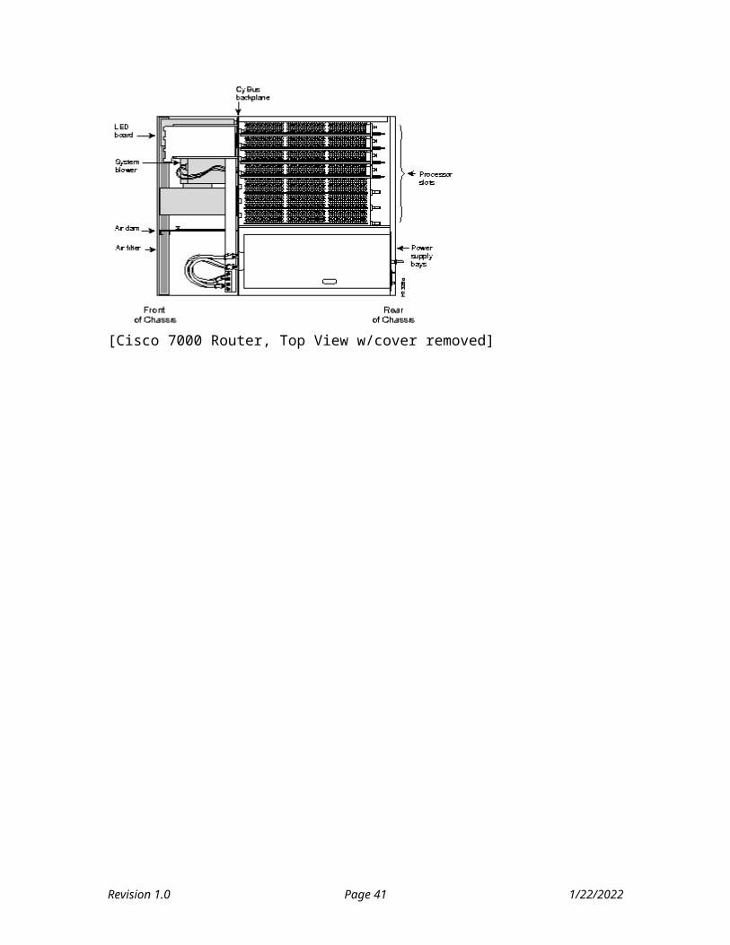
The Cisco 7000 is a core router designed for network backbone applications. It has dual power supplies for redundancy and 7 card slots for route processor, silicon switch processor and interface cards. The system backplane uses a “CX” bus. The route processor or “RP” and silicon switch processor or “SP” are required and contain the CPU, flash memory, DRAM memory, RS-232 console port, and switching hardware. This leaves 5 slots to accommodate “Interface Processor” cards. At the rear of the chassis from left to right, the slots are labeled “slot0”, “slot1”, “slot2”, “slot3”, “slot4”, “SP”, and “RP”. In our lab environment, the four 7000s have a FDDI card in slot 1, serial card in slot 2, and on R1 only an ethernet card in slot 2. The interface names in IOS depend on the slot containg the card. For example, an 8-port serial card in slot1 corresponds to interface names “serial1/0”, “serial1/1”, … “serial1/7”. The same card in slot 4 would be labeled “serial4/0”, “serial4/1”, … “serial4/7”. The 7000 chassis weighs 145 pounds when fully populated.
[Cisco 7000 Router, Front View]
Revision 1.0 Page 28 5/3/2023
[Cisco 7000 Router, Rear View]
[Cisco 7000 Router, Top View w/cover removed]
Revision 1.0 Page 29 5/3/2023
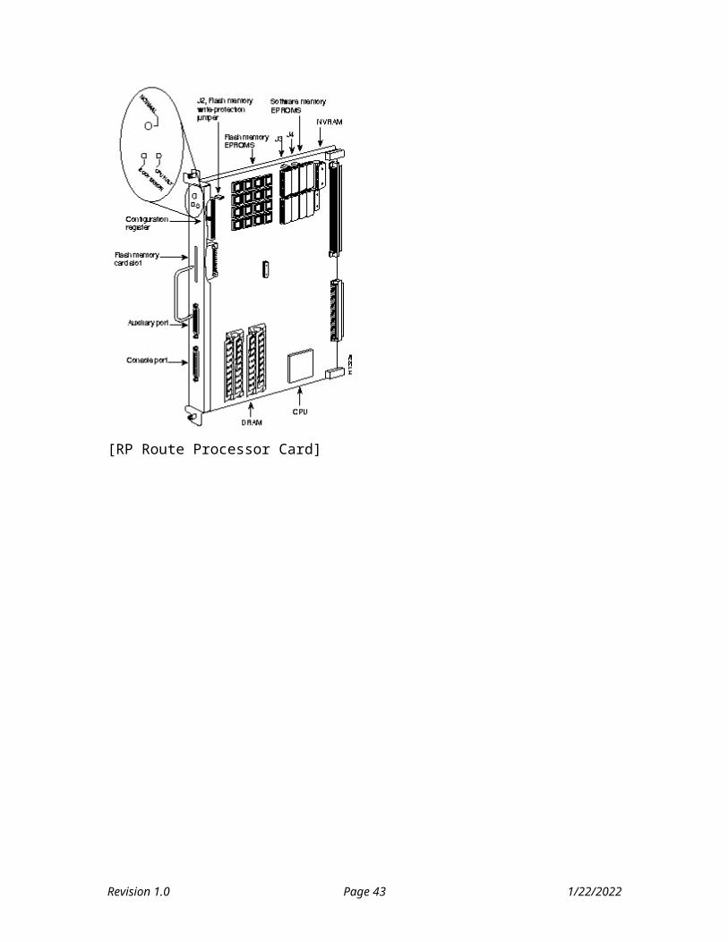
The route processor is the brains of the router and contains the CPU, configuration register, boot ROMs, FLASH, DRAM, console port, auxiliary port, etc. The CPU is a Motorola 68040. Our systems are configured with 64M DRAM and 4M flash. There is also a special NVRAM memory device (Non-Volatile RAM) used to hold the configuration file. When the system boots, it executes code in the boot ROM similar to a PC BIOS. The system checks the configuration register to determine whether to boot into the ROM monitor, load an image from flash, boot from the network ,etc. Normally, the system loads an IOS (Internetwork Operating System) image from FLASH memory into DRAM and begins execution. Executing from DRAM requires additional memory but has a performance advantage since DRAM access times are faster than FLASH memory access times. The routers can also accommodate additional FLASH memory in the form of a PCMCIA FLASH card that can be used for storing IOS images or configuration files.
[RP Route Processor Card]
Revision 1.0 Page 30 5/3/2023

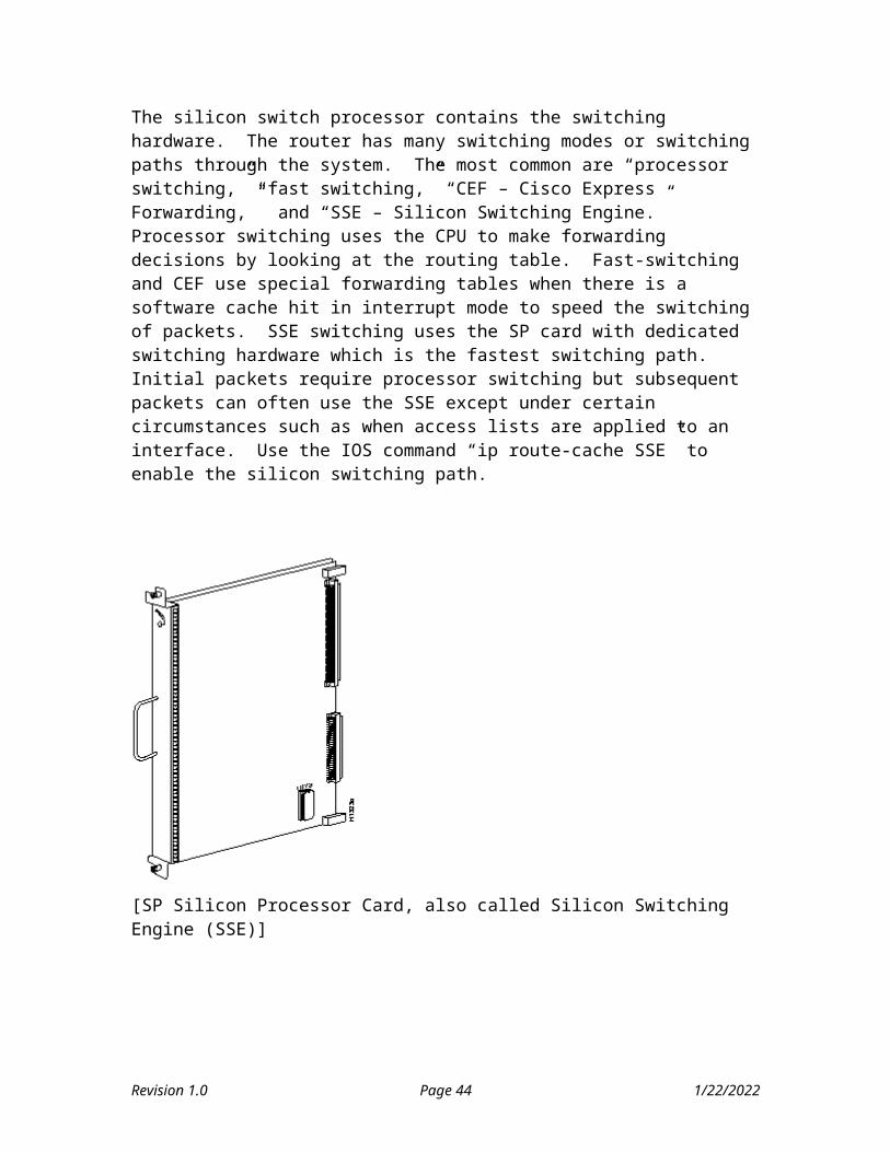
The silicon switch processor contains the switching hardware. The router has many switching modes or switching paths through the system. The most common are “processor switching,” “fast switching,” “CEF – Cisco Express Forwarding,” and “SSE – Silicon Switching Engine.” Processor switching uses the CPU to make forwarding decisions by looking at the routing table. Fast-switching and CEF use special forwarding tables when there is a software cache hit in interrupt mode to speed the switching of packets. SSE switching uses the SP card with dedicated switching hardware which is the fastest switching path. Initial packets require processor switching but subsequent packets can often use the SSE except under certain circumstances such as when access lists are applied to an interface. Use the IOS command “ip route-cache SSE” to enable the silicon switching path.
[SP Silicon Processor Card, also called Silicon Switching Engine (SSE)]
Revision 1.0 Page 31 5/3/2023
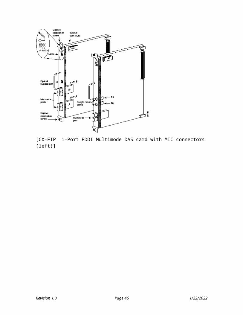
The CX-FIP or “CS-Bus FDDI Interface Processor” is a single port FDDI interface card. Our lab uses the type shown on the left with two multimode “MIC” FDDI connectors. It is a DAS (Dual-Attached Station) card with physical “A” and “B” ports. DAS devices are normally physically wired in a ring with a cable from the “A” port of router X to the “B” port of router X+1, where the last router’s “A” port connects to the first router’s “B” port. Each MIC connector has two singlemode 62.5/125 fibers, to form two counter-routing rings. FDDI is a reliable 100Mbps backbone token-ring technology that can survive a break by going into a “WRAP” state. All four lab 7000 routers have DAS ports and the lab 4500 router has a SAS port. Because they are not all DAS, our lab network is normally in a “WRAP” state and does not make a complete ring and therefore will not sustain a cut.
[Physical FDDI Wiring Diagram]
[FDDI MIC Connector]
[CX-FIP 1-Port FDDI Multimode DAS card with MIC connectors (left)]
Revision 1.0 Page 32 5/3/2023
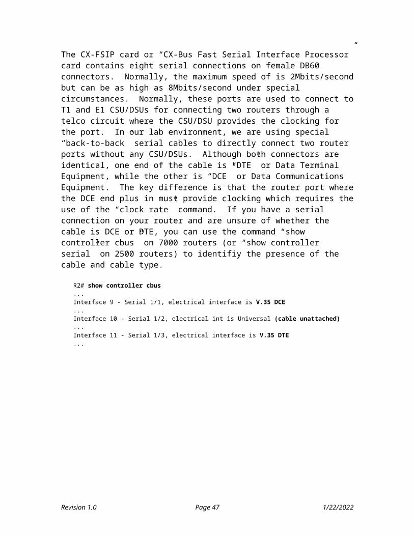
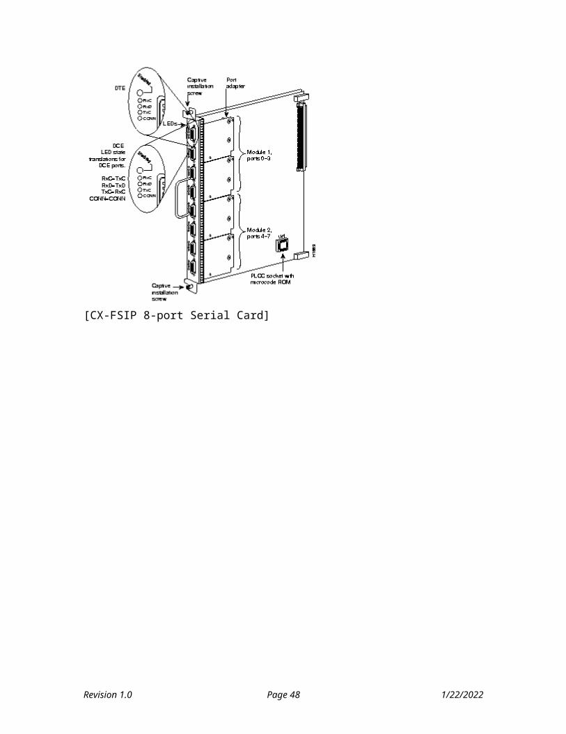
The CX-FSIP card or “CX-Bus Fast Serial Interface Processor” card contains eight serial connections on female DB60 connectors. Normally, the maximum speed of is 2Mbits/second but can be as high as 8Mbits/second under special circumstances. Normally, these ports are used to connect to T1 and E1 CSU/DSUs for connecting two routers through a telco circuit where the CSU/DSU provides the clocking for the port. In our lab environment, we are using special “back-to-back” serial cables to directly connect two router ports without any CSU/DSUs. Although both connectors are identical, one end of the cable is “DTE” or Data Terminal Equipment, while the other is “DCE” or Data Communications Equipment. The key difference is that the router port where the DCE end plus in must provide clocking which requires the use of the “clock rate” command. If you have a serial connection on your router and are unsure of whether the cable is DCE or DTE, you can use the command “show controller cbus” on 7000 routers (or “show controller serial” on 2500 routers) to identifiy the presence of the cable and cable type.
R2# show controller cbus...Interface 9 - Serial 1/1, electrical interface is V.35 DCE...Interface 10 - Serial 1/2, electrical int is Universal (cable unattached)...Interface 11 - Serial 1/3, electrical interface is V.35 DTE...
[CX-FSIP 8-port Serial Card]
Revision 1.0 Page 33 5/3/2023
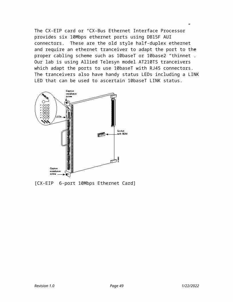
The CX-EIP card or “CX-Bus Ethernet Interface Processor” provides six 10Mbps ethernet ports using DB15F AUI connectors. These are the old style half-duplex ethernet and require an ethernet tranceiver to adapt the port to the proper cabling scheme such as 10baseT or 10base2 “thinnet”. Our lab is using Allied Telesyn model AT210TS tranceivers which adapt the ports to use 10baseT with RJ45 connectors. The tranceivers also have handy status LEDs including a LINK LED that can be used to ascertain 10baseT LINK status.
[CX-EIP 6-port 10Mbps Ethernet Card]
Revision 1.0 Page 34 5/3/2023
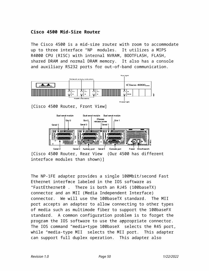
Cisco 4500 Mid-Size Router
The Cisco 4500 is a mid-size router with room to accommodate up to three interface “NP” modules. It utilizes a MIPS R4000 CPU (RISC) with internal NVRAM, BOOTFLASH, FLASH, shared DRAM and normal DRAM memory. It also has a console and auxiliary RS232 ports for out-of-band communication.
[Cisco 4500 Router, Front View]
[Cisco 4500 Router, Rear View (Our 4500 has different interface modules than shown)]
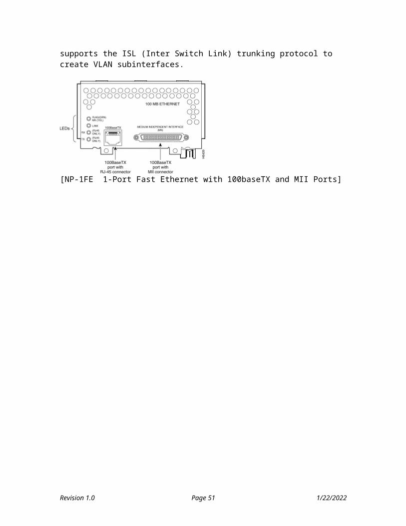
The NP-1FE adapter provides a single 100Mbit/second Fast Ethernet interface labeled in the IOS software as “FastEthernet0”. There is both an RJ45 (100baseTX) connector and an MII (Media Independent Interface) connector. We will use the 100baseTX standard. The MII port accepts an adapter to allow connecting to other types of media such as multimode fiber to support the 100baseFX standard. A common configuration problem is to forget the program the IOS software to use the appropriate connector. The IOS command “media-type 100baseX” selects the R45 port, while “media-type MII” selects the MII port. This adapter can support full duplex operation. This adapter also supports the ISL (Inter Switch Link) trunking protocol to create VLAN subinterfaces.
Revision 1.0 Page 35 5/3/2023
[NP-1FE 1-Port Fast Ethernet with 100baseTX and MII Ports]
Revision 1.0 Page 36 5/3/2023
The NP-1F-S-M adapter provides a single attached FDDI MIC interface using multimode fiber. Use a FDDI MIC/MIC cable to connect this device’s physical “S” port to one of the 7000 DAS “B” ports.
[NP-1F-S-M 1-Port FDDI Multimode SAS with MIC connector]
The NP-2E adapter provides two legacy 10Mbits/second half-duplex ethernet ports. It provides both an RJ45 (10baseT) and AUI interfaces. Under IOS, these interfaces are labeled as “Ethernet0” (bottom connector) and “Ethernet1” (top connector). The AUI interface is used with a transceiver to adapt to different ethernet media types such as 10base2. In our lab, we will be using the RJ45 10baseT port. A common configuration problem is to forget to specify which connector you are using under IOS. Use the command “media-type 10baseT” to select the RJ45 connector, or “media-type AUI” to select the AUI port.
[NP-2E 2-Port Ethernet with both 10baseT (RJ45) and AUI (DB15S) Connectors]
Revision 1.0 Page 37 5/3/2023
Cisco 2511 Access Server / Router
The Cisco 2511 is a small, non-expandable router. It utilizes a Motorola 68030 CPU with internal NVRAM, ROM, FLASH, and DRAM memory. It has two high speed serial ports suitable for speeds up to 2Mbits/second, a 10Mbit/second ethernet AUI port, and 16 asynchronous RS-232 ports. Two 68-pin SCSI style connectors provide 8 asynchronous ports each and use an octopus breakout cable (p/n CAB-OCTAL-ASYNC) to break into individual ports CAB-25AS-MMOD adapters adapt the octal cable to DB25M connectors which attach to the 7000 and 4500 DB25F console ports. This router was designed to provide a small platform to support up to 16 analog dialup modems, but in our lab environment we will be using a feature called “inverse telnet.” This feature allows us to connect to the router with a TELNET session and establish an RS232 terminal session with one of the async lines. These async lines are programmed for 9600 baud and connect to individual router console ports. This provides out-of-band access to program the lab routers, even when they are not in a working configuration.
[Cisco 2511 Access Server / Router]
[Octopus Cable CAB-OCTAL-ASYNC]
[RJ45S-DB25M Adapter CAB-25AS-MMOD]
Revision 1.0 Page 38 5/3/2023
Cisco 3548XL and 3524XL Ethernet Switches
A Cisco 3524XL ethernet switch is used to connect the lab router ethernet and fast ethernet ports. This switch uses a 1000baseSX GBIC adapter across multimode fiber cable to physically connect to two 3548XL ethernet switches that provide 96 10/100 ethernet ports to connect to student PCs in the networking lab. The switches use the ISL trunking protocols to implement VLANs that span the three switching allowing the switches to be configured to group the router ethernet ports and student computer ports in any desired configuration. This provides a lot of flexability for building different labs. For ease of programming, the console port of the switch connects to an async line on the 2511 to provide out-of-band access for configuration.
[Cisco 3524XL Ethernet Switch with 24 10/100 ethernet ports + 2 GigE ports]
[Cisco 3548XL Ethernet Switch with 48 10/100 ethernet ports + 2 GigE ports]
Revision 1.0 Page 39 5/3/2023
Appendix B: Router IOS Software
The ITL lab Cisco routers use the Internetwork Operating System (IOS) software. The IOS software is typically stored as a compressed binary image in flash. Lower end platforms (25xx) execute code directly from flash while higher end platforms (45xx,7xxx) copy the code from FLASH to DRAM to take advantage of faster DRAM memory access times. Most of IOS is written in the C Programming Language and cross-compiled with the GNU C compiler for each router architecture. Software is distributed as binary images, usually through downloading from a password protected area on the Cisco web site. There are many different versions indicated by a major version number, minor version number, release level, and optionally “train”. Within a given version, there are “feature sets” which generally determine which protocols are supported. Sometimes features available only in the enterprise feature set are incorporated into the baseline IP feature set in subsequent versions such as network address translation (NAT). There are about twenty different feature sets, but the most important are as follows:
- IP (IP Protocol and Bridging Only)- DESKTOP (adds support for IPX, Appletalk, and DECnet)- ENTERPRISE (adds support for Apollo,Banyan,ISO CLNS,XNS,etc.)
Software versions have minimum DRAM and FLASH memory requirements. On the Cisco ITL routers, we have chosen to use the most stable version of IOS software with the largest feature sets that will fit in available memory to maximize flexibility as follows:
MODEL DRAM FLASH VER FEATURE IMAGER1 7000 64M 4M 11.1(24) ENTERPRISE gs7-j-mz.111-24.binR2 7000 64M 4M 11.1(24) ENTERPRISE gs7-j-mz.111-24.binR3 7000 64M 4M 11.1(24) ENTERPRISE gs7-j-mz.111-24.binR4 7000 64M 4M 11.1(24) ENTERPRISE gs7-j-mz.111-24.binR5 4500 48M 8M 12.0(13) ENTERPRISE + IPSEC c4500-js56i-mz.120-13.binR6 2511 4M 8M 12.0(13) DESKTOP c2500-d-l.120-13.bin
As of this writing, the most current IOS software version is 12.1(5) which is supported on the 4500 and 2511 platforms but would require additional memory. The Cisco 7000 has reached its end of life and the most recent software version supported is 11.2(24). Running the enterprise 11.2(24) software is possible on the lab 7000s but would require a 8M PCMCIA flash card and BIOS BOOT ROM upgrade as the current v10.0(7) BOOT ROMs do not understand PCMCIA flash cards and the image will not fit in the internal 4M flash memory.
In summary, the most important protocols like IP, IPX, and Appletalk are present on all routers. Network Address Translation (NAT) which was not incorporated until version 11.3 is only present on routers R5 and R6.
Revision 1.0 Page 40 5/3/2023
Appendix C: IOS Software Documentation
The Cisco IOS documentation is available in three forms – (1) world-wide-web, (2) CD-ROM, and (3) hardcopy manuals.
- WORLD-WIDE-WEBThe documentation on the Cisco web page does not require any special accounts or passwords. The URL is http://www.cisco.com. From the home page, go to Technical Documents Documentation Home Page Cisco IOS Software Configuration. From this point, choose the appropriate software version. The documents are available in both hypertext (for viewing) and PDF (for printing).
- CD-ROMThe same documentation is available on a single CD-ROM which is distributed with new router equipment. It requires a Microsoft Windows 95/98/NT/2000 PC and contains the manuals in hypertext format and includes a search engine. This is a handy form when your network is broken or you do not have access to the Internet.
- HARDCOPY The manuals are also available as a set of hard copy volumes. Two small volumes have an index of the command reference volumes and configuration guide volumes. The volumes are 8.5”x11”. As of version 12.1, the full set requires approximately 5 linear feet of shelf space.
Since IOS v11.1, many new features have been added and the number of manual pages has increased around five-fold as of version 12.1. Most of the commands in the earlier versions will still work with newer software although occasionally some of the default behaviors have changed. When studying the core IP routing protocols, the v11.1 manuals are probably the best source of information as much of the extraneous new features are not present. The IOS v11.1 manuals are organized as follows:
- Configuration Fundamentalso User Interfaceo Configuration Files
- Access Serviceso Terminal Lineso PPP/SLIPo Telnet
- Wide Area Networkso ATMo Frame-Relayo ISDNo X.25
- Network Protocols, Part 1
Revision 1.0 Page 41 5/3/2023

o Appletalko IPo IPXo IP Routing Protocols
RIP OSPF IGRP EIGRP BGP IS-IS
- Network Protocols, Part 2o Apollo Domaino Banyan Vineso DECneto ISO CLNSo Xerox XNS
- Bridging and IBM Networkingo Transparent Bridgingo Source-Route Bridgingo DLSW
For each topic, there are configuration guides and command references. The configuration guides address groups of related commands, explain more of the theory, and have more complex examples. The command references are generally alphabetized listings of configuration commands that detail the command syntax
Revision 1.0 Page 42 5/3/2023
Appendix D: Cisco Router Password Recovery Procedure
On occasion, the router password may be forgotten and need to be recovered. The following procedure may be used to recover from a situation where the password is lost provided you have physical access to the router.
Cisco routers use a 16 bit configuration register to control how the system will boot and are normally set to the value 0x2102. Bit 6 of this register controls whether the router will load the startup configuration upon booting (bit 6 is clear), or simply start with an empty configuration (bit 6 is set). The basic idea is to power cycle the router with a dumb terminal or emulator attached to the console port. Within the first 60 seconds of booting, send a BREAK signal to the router to make it stop the boot process. You then change the configuration register from the default value of 0x2102 to 0x2142, and reboot the system. You will often get a configuration dialog when the system reboots where you simply press control-C to abort the dialog. You will now be at the command prompt “Router>” where you type the “enable” command where the prompt will change to “Router#” without prompting for a password. At this point, you copy the startup configuration into the running configuration, however, all interfaces are shut down and must be manually enabled. Now you can change the console, vty, and enable passwords. You must then copy the new running configuration to the startup configuration, change the configuration register back to 0x2102, then reboot. The procedure is slightly different among the different router platforms and is detailed below.
1. Physically connect a dumb terminal or PC with a terminal emulator such as HyperTerm to the router console port.
2. Configure your terminal or emulator for the following settings:a. 9600 baud rateb. no parityc. 8 data bitsd. 1 stop bite. no flow control
3. Power cycle the router to make it reboot and send a BREAK signal from the terminal within the first 60 seconds to stop the boot process and enter the ROM monitor. (Control-BREAK in HyperTerm).
4. Change the configuration register from the default value 0x2102 to 0x2142 so the router will ignore the stored configuration with unknown passwords upon reboot. Afterwards, reboot the router.
Cisco 7000 Routers:System Bootstrap, Version 5.0(7), RELEASE SOFTWARECopyright (c) 1986-1994 by cisco SystemsRP1 processor with 65536 Kbytes of main memory
Revision 1.0 Page 43 5/3/2023
F3: 3559856+114640+289292 at 0x1000Abort at 0x2C8AC (PC)>o/r 0x2142>i
Cisco 4500 Routers:System Bootstrap, Version 5.1(1) [daveu1], RELEASE SOFTWARECopyright (c) 1994 by cisco Systems, Inc. monitor: command "cisco2-C4500" aborted due to user interruptrommon 1 > confreg 0x2142You must reset or power cycle for new config to take effectrommon 2 > reset
Cisco 2500 Routers:System Bootstrap, Version 5.2(8a), RELEASE SOFTWARECopyright (c) 1986-1995 by cisco Systems2500 processor with 2048 Kbytes of main memoryAbort at 0x10EA87C (PC)>o/r 0x2142>i
5. Upon rebooting, the router will normally start a dialog asking if you want it to help you configure the system. Abort this dialog by typing control-C (^C).
Would you like to enter the initial config dialog? [yes]: ^C
6. Wait a moment and hit return a few times. You should get the non-enabled router prompt “Router>”. Type “enable” <cr> and the prompt should change to “Router#”.
Router> enable
7. Copy the startup configuration to the running configuration as your starting point.
Router# copy startup-config running-config
8. Note which interfaces are present as they will be administratively shut down and will need to be manually enabled.
Router# show ip interface brief
9. Go into configuration mode and enable each interface as appropriate.
Router# config termRouter(config)#int e0Router(config-if)#no shutdown Router(config)#int fddi0Router(config-if)#no shutdown
10. Set the enable, console, and vty password. If you are using the “enable secret” mechanism, set it as well. Here we will use the password “cisco”.
Router(config-if)#enable password cisco {weak encryption}Router(config-if)#enable secret cisco {strong encryption}Router(config)#line con 0Router(config-line)#password ciscoRouter(config-line)#line vty 0 4
Revision 1.0 Page 44 5/3/2023

Router(config-line)#password cisco. . .
11. Change the configuration register back to the default value 0x2102 to take effect upon the next reboot.
Router(config-line)# config-reg 0x2102
12. Get out of the configuration mode by pressing control-Z (^Z) and save your changes by copying them to the startup configuration.
Router(config)# ^ZRouter# copy running-config startup-config
13. Reboot the router
Router# reloadProceed with reload? [confirm] y
14. After rebooting, the router will accept the new password.
Revision 1.0 Page 45 5/3/2023
Appendix E: Cisco 2511 Firewall Router Configuration
version 12.0service timestamps debug datetime localtime show-timezoneservice timestamps log datetime localtime show-timezoneservice password-encryptionservice udp-small-serversservice tcp-small-servers!hostname fw/r6!enable secret level 2 5 $1$wLUZ$SjI2kZwadyltWehijBOvj0enable secret 5 $1$I9LE$c5KYutJeq/gmRcYNb4z3B0!ip subnet-zeroip host r1 2001 128.186.121.88ip host r2 2002 128.186.121.88ip host r3 2003 128.186.121.88ip host r4 2004 128.186.121.88ip host r5 2005 128.186.121.88ip host cat1 2007 128.186.121.88ip host s1 2008 128.186.121.88ip name-server 128.186.121.10clock timezone EST -5clock summer-time EDT recurring!!interface Loopback0 ip address 192.168.66.6 255.255.255.0 no ip directed-broadcast ip nat inside!interface Ethernet0 ip address 128.186.121.88 255.255.255.0 no ip directed-broadcast ip nat outside!interface Serial0 description Link to R1 S1/6 ip address 192.168.16.6 255.255.255.0 no ip directed-broadcast ip nat inside clockrate 2000000!interface Serial1 description Link to R3 S1/6 bandwidth 2000 ip address 192.168.36.6 255.255.255.0 no ip directed-broadcast ip nat inside clockrate 2000000!router eigrp 100 redistribute static metric 10000 100 255 128 1500 network 192.168.16.0 network 192.168.36.0 network 192.168.66.0!router ospf 100 network 192.168.16.0 0.0.0.255 area 0 network 192.168.36.0 0.0.0.255 area 0
Revision 1.0 Page 46 5/3/2023
default-information originate always!router rip network 192.168.16.0 network 192.168.36.0 network 192.168.66.0 default-metric 5!router igrp 100 network 192.168.16.0 network 192.168.36.0 network 192.168.66.0!ip nat inside source list rfc1918 interface Ethernet0 overloadip nat inside source static 192.168.10.2 128.186.121.90ip nat inside source static 192.168.10.3 128.186.121.89ip http serverip classlessip route 0.0.0.0 0.0.0.0 128.186.121.1!ip access-list standard rfc1918 permit 192.168.0.0 0.0.255.255 permit 172.16.0.0 0.15.255.255 permit 10.0.0.0 0.255.255.255 deny any!ip access-list extended fw-in permit tcp any any established permit ip host 128.186.121.41 any permit ip host 128.186.121.10 any permit ip host 128.186.2.206 any deny tcp any any eq telnet deny tcp any host 128.186.121.88 range 2001 2017 permit udp any any eq ntp permit udp any any eq snmp permit udp any any eq 22 permit udp any eq ntp any permit udp any eq snmp any permit udp any eq 22 any deny tcp any any deny udp any any permit icmp any anysnmp-server community public ROprivilege router level 15 networkprivilege interface level 15 ip addressprivilege interface level 15 ipprivilege configure level 15 interfaceprivilege exec level 2 moreprivilege exec level 2 tracerouteprivilege exec level 2 pingprivilege exec level 2 show running-configprivilege exec level 2 show configurationprivilege exec level 2 showprivilege exec level 2 clear lineprivilege exec level 2 clear countersprivilege exec level 2 clear!line con 0 password 7 030752180500 login transport input noneline 1 16 no exec
Revision 1.0 Page 47 5/3/2023
modem InOut transport input all transport output noneline aux 0 password 7 09495E0410091201line vty 0 4 exec-timeout 60 0 password 7 104D000A0618 login!ntp server 128.186.121.10end
Revision 1.0 Page 48 5/3/2023
Appendix F: Baseline Router Configuration
In order to quickly get the student ITL routers r1, r2, r3, r4, and r5 working with a rudimentary RIP setup, baseline configurations have been written. Since routers r1 through r5 each had a small amount of free space on their internal flash memory used to hold the Cisco IOS software, a small baseline configuration file has been saved. This may be a bit more convenient than using a terminal emulator copy and paste capabilities. On each router r1 through r5, two steps are required:
1. Copy the appropriate baseline configuration file in flash to the startup-configuration non-volatile memory using the command (Replace X with the integer router identifier):
RouterX# copy flash:base-rX.cfg startup-config
2. Reboot the router using the “reload” command:
RouterX# reload
r5#dir flash:Directory of flash:/
1 -rw- 6558840 <no date> c4500-js56i-mz.120-13.bin 2 -rw- 1148 <no date> base-r5.cfg
8388608 bytes total (1828492 bytes free)r5#copy flash:base-r5.cfg startup-configDestination filename [startup-config]? [OK]1148 bytes copied in 0.156 secsr5#reloadProceed with reload? [confirm]y00:02:11: %SYS-5-RELOAD: Reload requestedSystem Bootstrap, Version 5.1(1) [daveu 1], RELEASE SOFTWARE (fc1)Copyright (c) 1994 by cisco Systems, Inc.C4500 processor with 32768 Kbytes of main memory
Self decompressing the image : ####[OK]
Cisco Internetwork Operating System Software IOS (tm) 4500 Software (C4500-JS56I-M), Version 12.0(13), RELEASE SOFTWARE (fc1)...cisco 4500 (R4K) processor (revision 0x00) with 32768K/16384K bytes of memory....Press RETURN to get started!r5>enablePassword: r5#
Alternatively, you can erase the startup configuration, reboot the router, skip the initial configuration dialog, enter privileged mode, enter configuration mode, and paste the appropriate configuration commands.
Revision 1.0 Page 49 5/3/2023
1. Erase the startup configuration using the “write erase” command.2. Reboot the router using the “reload” command.3. After reboot, when prompted by the initial configuration dialog, exit with
control-C.4. Enter the enable mode with the command “enable”.5. Enter the configuration mode with the command “config term”6. Copy the appropriate text configuration into the clipboard. (In notepad,
wordpad, or Microsoft Word, highlight the configuration text and select EditCopy.)
7. Inside your terminal emulator, paste the clipboard contents to the router. (In the MS-Windows TELNET program, use EditPaste.)
8. Exit the configuration mode with control-Z.9. Issue the “write” command to save your changes to non-volatile memory.
r5#write eraseErasing nvram filesystem will remove all files! Continue? [confirm]y[OK]Erase of nvram: completer5#r5#reloadProceed with reload? [confirm]y00:17:06: %SYS-5-RELOAD: Reload requestedSystem Bootstrap, Version 5.1(1) [daveu 1], RELEASE SOFTWARE (fc1)
--- System Configuration Dialog ---
Would you like to enter the initial configuration dialog? [yes/no]:^C...Press RETURN to get started!...Router>Router>enableRouter#config termEnter configuration commands, one per line. End with CNTL/Z.Router(config)#(Paste the configuration text here)Router(config)#^ZRouter#00:02:40: %SYS-5-CONFIG_I: Configured from console by consoleRouter#writeBuilding configuration...[OK]Router#
Revision 1.0 Page 50 5/3/2023
The following is the baseline router configuration. See also the “baseline” subdirectory on the accompanying project CD-ROM.
COMMON:service udp-small-serversservice tcp-small-serversenable password ciscono ip domain-lookupno ip classlesslogging bufferedsnmp-server community public ROline con 0 exec-timeout 0 0line aux 0line vty 0 4 password cisco login
R1:hostname r1interface Loopback0 ip address 192.168.11.1 255.255.255.0 no shutdowninterface Fddi0/0 ip address 192.168.1.1 255.255.255.0 no shutdowninterface Serial1/2 description Link to R2 S1/1 ip address 192.168.12.1 255.255.255.0 bandwidth 2000 no shutdowninterface Serial1/3 description Link to R3 S1/1 ip address 192.168.13.1 255.255.255.0 bandwidth 2000 no shutdowninterface Serial1/4 description Link to R4 S1/1 ip address 192.168.14.1 255.255.255.0 bandwidth 2000 no shutdowninterface Serial1/6 description Link to R6 S0 ip address 192.168.16.1 255.255.255.0 bandwidth 2000 no shutdowninterface E2/0 description Vlan 10 to cat1 FA0/1 ip address 192.168.10.1 255.255.255.0 no shutdowninterface E2/1 description Vlan 20 to cat1 FA0/2 ip address 192.168.20.1 255.255.255.0 no shutdowninterface E2/2 description Vlan 30 to cat1 FA0/3 ip address 192.168.30.1 255.255.255.0 no shutdowninterface E2/3 description Vlan 40 to cat1 FA0/4 ip address 192.168.40.1 255.255.255.0 no shutdowninterface E2/4 description Vlan 50 to cat1 FA0/5 ip address 192.168.50.1 255.255.255.0 no shutdowninterface E2/5 description Vlan 60 to cat1 FA0/6
ip address 192.168.60.1 255.255.255.0 no shutdownrouter rip network 192.168.11.0 network 192.168.12.0 network 192.168.13.0 network 192.168.14.0 network 192.168.16.0 network 192.168.1.0 network 192.168.10.0 network 192.168.20.0 network 192.168.30.0 network 192.168.40.0 network 192.168.50.0 network 192.168.60.0
R2:hostname r2interface Loopback0 ip address 192.168.22.2 255.255.255.0 no shutdowninterface Fddi0/0 ip address 192.168.1.2 255.255.255.0 no shutdowninterface Serial1/1 description Link to R1 S1/2 ip address 192.168.12.2 255.255.255.0 bandwidth 2000 clockrate 2000000 no shutdowninterface Serial1/3 description Link to R3 S1/2 ip address 192.168.23.2 255.255.255.0 bandwidth 2000 no shutdowninterface Serial1/4 description Link to R4 S1/2 ip address 192.168.24.2 255.255.255.0 bandwidth 2000 no shutdownrouter rip network 192.168.12.0 network 192.168.22.0 network 192.168.23.0 network 192.168.24.0 network 192.168.1.0
R3:hostname r3interface Loopback0 ip address 192.168.33.3 255.255.255.0 no shutdowninterface Fddi0/0 ip address 192.168.1.3 255.255.255.0 no shutdowninterface Serial1/0 description Link to self no ip address bandwidth 2000 no shutdowninterface Serial1/1 description Link to R1 S1/3 ip address 192.168.13.3 255.255.255.0 bandwidth 2000
Revision 1.0 Page 51 5/3/2023
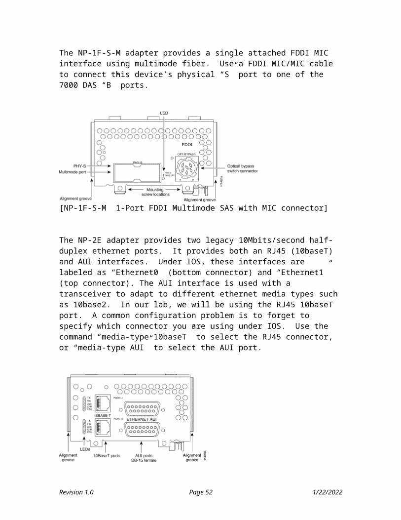
clockrate 2000000 no shutdowninterface Serial1/2 description Link to R2 S1/3 ip address 192.168.23.3 255.255.255.0 bandwidth 2000 clockrate 2000000 no shutdowninterface Serial1/3 description Link to self no ip address bandwidth 2000 clockrate 2000000 no shutdowninterface Serial1/4 description Link to R4 S1/3 ip address 192.168.34.3 255.255.255.0 bandwidth 2000 no shutdowninterface Serial1/6 description Link to R6 S1 ip address 192.168.36.3 255.255.255.0 bandwidth 2000 no shutdownrouter rip network 192.168.33.0 network 192.168.13.0 network 192.168.23.0 network 192.168.34.0 network 192.168.36.0 network 192.168.1.0
R4:hostname r4interface Loopback0 ip address 192.168.44.4 255.255.255.0 no shutdowninterface Fddi0/0 description Link to R5 FDDI0 ip address 192.168.1.4 255.255.255.0 no shutdowninterface Serial1/1 description Link to R1 S1/4 ip address 192.168.14.4 255.255.255.0 bandwidth 2000 clockrate 2000000 no shutdowninterface Serial1/2 description Link to R2 S1/4
ip address 192.168.24.4 255.255.255.0 bandwidth 2000 clockrate 2000000 no shutdowninterface Serial1/3 description Link to R3 S1/4 ip address 192.168.34.4 255.255.255.0 bandwidth 2000 clockrate 2000000 no shutdownrouter rip network 192.168.44.0 network 192.168.14.0 network 192.168.24.0 network 192.168.34.0 network 192.168.1.0
R5:hostname r5interface loopback0 ip address 192.168.55.5 255.255.255.0 no shutdowninterface FastEthernet0 description Vlan70 to cat1 FA0/7 ip address 192.168.70.1 255.255.255.0 media-type 100BaseX no shutdowninterface Ethernet0 description Vlan80 to cat1 FA0/8 ip address 192.168.80.1 255.255.255.0 media-type 10BaseT no shutdowninterface Ethernet1 description Vlan90 to cat1 FA0/9 ip address 192.168.90.1 255.255.255.0 media-type 10BaseT no shutdowninterface Fddi0 description Link to R4 FDDI0/0 ip address 192.168.1.5 255.255.255.0 no keepalive no shutdownrouter rip network 192.168.55.0 network 192.168.70.0 network 192.168.80.0 network 192.168.90.0 network 192.168.1.0
Revision 1.0 Page 52 5/3/2023

Appendix G: Linux Scripts
There an expect script available to execute commands on routers, cisexec, and another more dangerous script, ciscfg, that can automatically modify a router’s configuration. These two scripts were downloaded from the Chesapeake Computer Consultants web site http://www.ccci.com and were modified slightly to work under Linux. A small PERL script, cis2inv.pl, was also written to take output from one of the expect scripts to produce a comma delimited file suitable for Microsoft Excel import with IOS and memory information on the router to produce tables like that shown below.
ROUTER CPU IOS VER IOS IMAGE BOOT ROM FLASH DRAM192.168.11.1 RP1 (68040) 11.1(24) gs7-j-mz.111-24.bin 5.0(7) 4096 65536192.168.22.2 RP1 (68040) 11.1(24) gs7-j-mz.111-24.bin 5.0(7) 4096 65536192.168.33.3 RP1 (68040) 11.1(24) gs7-j-mz.111-24.bin 5.0(5) 4096 65536192.168.44.4 RP1 (68040) 11.1(24) gs7-j-mz.111-24.bin 5.2(9) 4096 65536192.168.55.5 4500 (R4K) 12.0(13) flash:c4500-js56i-mz.120-13.bin 5.1(1) 4096 49152192.168.66.6 2511 (68030) 12.0(13) flash:c2500-d-l.120-13.bin 5.2(8a) 8192 4096
To use these scripts, you must create a text file with the router passwords. For example, if the login password is “cisco” and enable password also “cisco”, a text file like this is required. The first column specifies the router name which can include the wildcard ‘*’.
[curci@s1 cisinfo]$ cat key.dat* cisco cisco
Before using the expect scripts, you must set an environment variable named “CISCOPASSWORDS” to point to the file with the passwords.
[Borne Shell Example]Linux$ CISCOPASSWORDS=key.datLinux$ export CISCOPASSWORDS
[C-Shell Example]Linux$ setenv CISCOPASSWORDS key.dat
It is also convenient to have a text file with a list of router IP addresses that can be given as an argument.
[curci@s1 cisinfo]$ cat routers192.168.11.1192.168.22.2192.168.33.3192.168.44.4192.168.55.5
The cisexec script simply uses TELNET to log into each router specified and executes a list of commands given as arguments. Here is an example where I use cisexec to display the clock on routers r1 through r5. The first try is unsuccessful, because I forget to define the environment variable CISCOPASSWORDS, while the second try works.
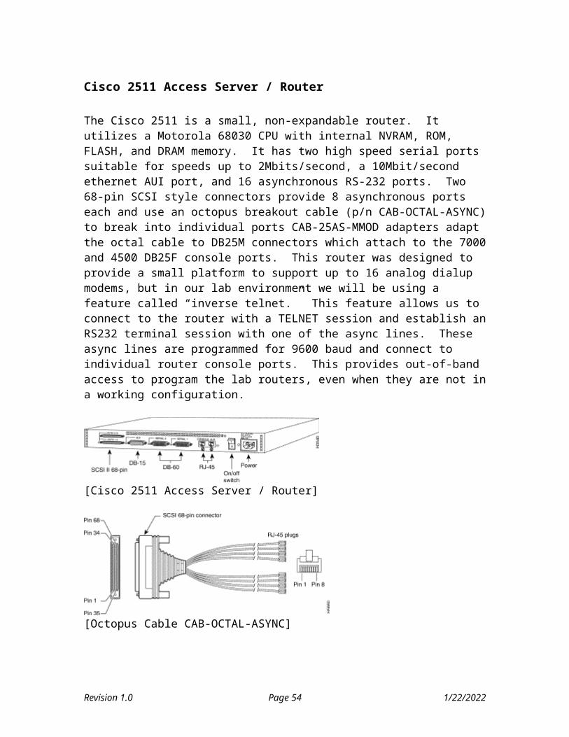
[curci@s1 cisinfo]$ ./cisexec "show clock" ./routersEnvironment variable CISCOPASSWORDS not set, exiting...
[curci@s1 cisinfo]$ CISCOPASSWORDS=key.dat[curci@s1 cisinfo]$ export CISCOPASSWORDS[curci@s1 cisinfo]$ ./cisexec "show clock" ./routers
spawn telnet 192.168.11.1 Trying 192.168.11.1...Connected to 192.168.11.1.User Access VerificationPassword: r1>terminal length 0r1> show clock 12:52:56.077 EST Fri Nov 24 2000r1>
spawn telnet 192.168.22.2 Trying 192.168.22.2...Connected to 192.168.22.2.User Access VerificationPassword: r2>terminal length 0r2> show clock *17:52:53.474 UTC Fri Nov 24 2000r2>
spawn telnet 192.168.33.3 Trying 192.168.33.3...Connected to 192.168.33.3.User Access VerificationPassword: r3>terminal length 0r3> show clock *17:53:01.310 UTC Fri Nov 24 2000r3>
spawn telnet 192.168.44.4 Trying 192.168.44.4...Connected to 192.168.44.4.User Access VerificationPassword: r4>terminal length 0r4> show clock *17:52:44.474 UTC Fri Nov 24 2000r4>
spawn telnet 192.168.55.5 Trying 192.168.55.5...Connected to 192.168.55.5.User Access VerificationPassword: r5>terminal length 0r5> show clock *17:53:02.346 UTC Fri Nov 24 2000r5>
To execute a privileged command, you must use the ‘-p’ option which forces the script to first change the router to enabled mode before executing the commands. It is also
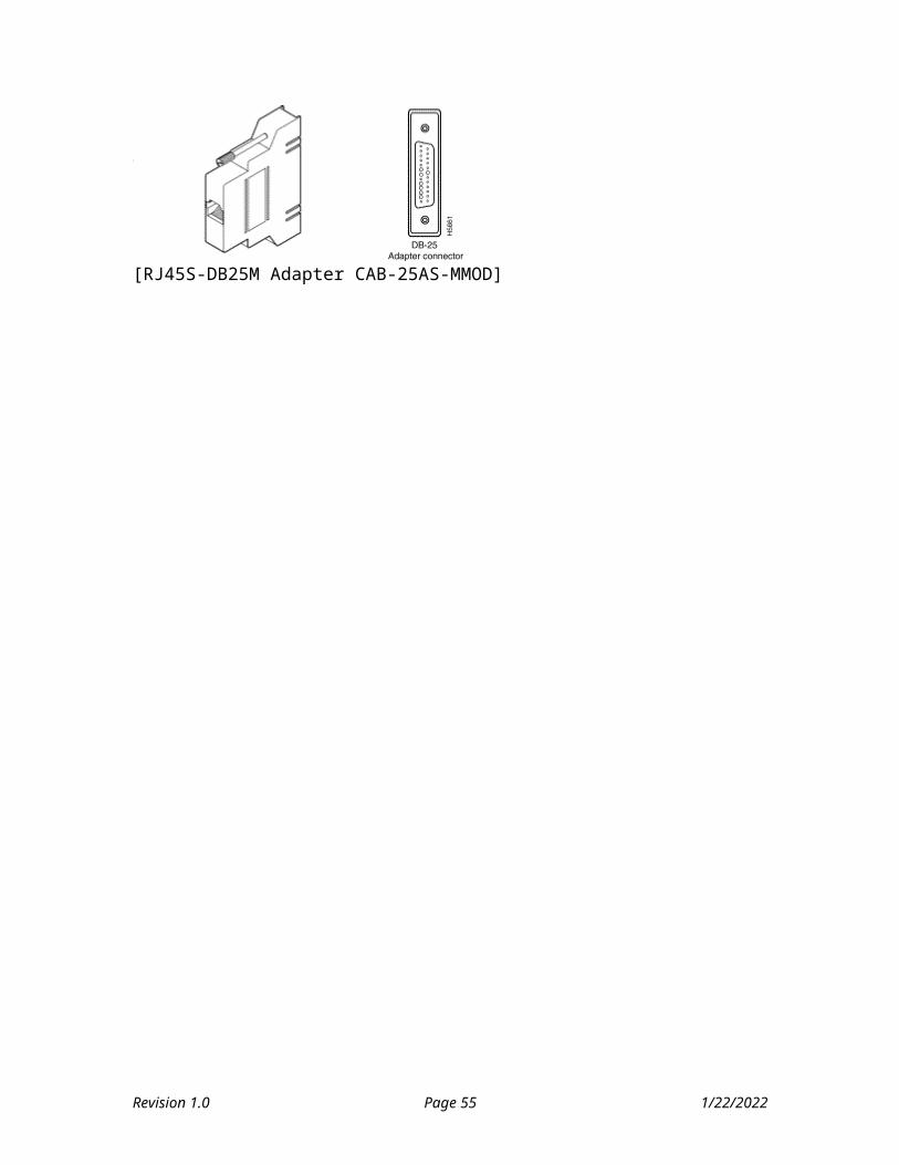
possible to execute multiple commands separated with a semi-colon. Instead of using a filename containing IP addresses of the routers, you can list the routers individually.
Linux$./cisexec -p “sh run;sh ver;sh ip ro” 192.168.11.1 192.168.22.2
With the cisexec utility, several extraneous lines, blank lines, and carriage return characters get logged in the capture. I have also written a small wrapper script to remove these.
Linux$ cat go#! /bin/sh## 20-Nov-2000 R.Curci# Borne shell script to execute ./cisexec but remove extranous# parts of the captured session, consecutive blank lines, # and carriage return '\r' (ASCII 13 decimal) characters.#CISCOPASSWORDS=key.datexport CISCOPASSWORDS#for x in 1 2 3 4 5do h=192.168.$x$x.$x ./cisexec -p "$1" $hdone |egrep -v '(^spawn|^Trying|^Connect|^User Acc|>enable)' |egrep -v '(terminal length 0|^Password:|^Escape character)' |tr -d '\r' | uniq
Here is a sample execution where we execute the “show cdp neighbor” command to see which devices are adjacent using the data link Cisco Discovery Protocol (CDP).
[curci@s1 cisinfo]$ ./go "show cdp neighbor"r1# show cdp neighbors Capability Codes: R - Router, T - Trans Bridge, B - Source Route Bridge S - Switch, H - Host, I - IGMP, r - Repeater
Device ID Local Intrfce Holdtme Capability Platform Port IDr2 Ser 1/2 122 R RP1 Ser 1/1r2 Fddi0/0 122 R RP1 Fddi0/0r3 Ser 1/3 135 R RP1 Ser 1/1r3 Fddi0/0 135 R RP1 Fddi0/0r4 Ser 1/4 134 R RP1 Ser 1/1r4 Fddi0/0 134 R RP1 Fddi0/0cat1 Eth 2/5 162 T S WS-C3524-XFas 0/6cat1 Eth 2/4 162 T S WS-C3524-XFas 0/5cat1 Eth 2/3 162 T S WS-C3524-XFas 0/4cat1 Eth 2/2 162 T S WS-C3524-XFas 0/3cat1 Eth 2/1 162 T S WS-C3524-XFas 0/2cat1 Eth 2/0 162 T S WS-C3524-XFas 0/1r5 Fddi0/0 121 R 4500 Fddi0fw/r6 Ser 1/6 144 R 2511 Ser 0r1#
r2# show cdp neighbors Capability Codes: R - Router, T - Trans Bridge, B - Source Route Bridge S - Switch, H - Host, I - IGMP, r - Repeater
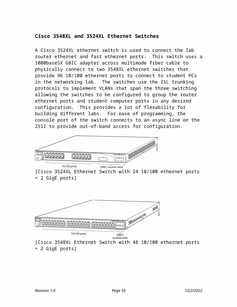
Device ID Local Intrfce Holdtme Capability Platform Port IDr3 Ser 1/3 131 R RP1 Ser 1/2r3 Fddi0/0 131 R RP1 Fddi0/0r1 Fddi0/0 139 R RP1 Fddi0/0r1 Ser 1/1 139 R RP1 Ser 1/2r4 Ser 1/4 130 R RP1 Ser 1/2r4 Fddi0/0 130 R RP1 Fddi0/0r5 Fddi0/0 177 R 4500 Fddi0r2#
r3# show cdp neighbors Capability Codes: R - Router, T - Trans Bridge, B - Source Route Bridge S - Switch, H - Host, I - IGMP, r - Repeater
Device ID Local Intrfce Holdtme Capability Platform Port IDr2 Ser 1/2 174 R RP1 Ser 1/3r2 Fddi0/0 173 R RP1 Fddi0/0r3 Ser 1/3 127 R RP1 Ser 1/0r3 Ser 1/0 127 R RP1 Ser 1/3r1 Fddi0/0 135 R RP1 Fddi0/0r1 Ser 1/1 135 R RP1 Ser 1/3r4 Ser 1/4 126 R RP1 Ser 1/3r4 Fddi0/0 125 R RP1 Fddi0/0r5 Fddi0/0 173 R 4500 Fddi0fw/r6 Ser 1/6 136 R 2511 Ser 1r3#
r4# show cdp neighbors Capability Codes: R - Router, T - Trans Bridge, B - Source Route Bridge S - Switch, H - Host, I - IGMP, r - Repeater
Device ID Local Intrfce Holdtme Capability Platform Port IDr2 Fddi0/0 169 R RP1 Fddi0/0r2 Ser 1/2 169 R RP1 Ser 1/4r3 Fddi0/0 123 R RP1 Fddi0/0r3 Ser 1/3 123 R RP1 Ser 1/4r1 Fddi0/0 131 R RP1 Fddi0/0r1 Ser 1/1 131 R RP1 Ser 1/4r5 Fddi0/0 169 R 4500 Fddi0r4#
r5# show cdp neighbors Capability Codes: R - Router, T - Trans Bridge, B - Source Route Bridge S - Switch, H - Host, I - IGMP, r - Repeater
Device ID Local Intrfce Holdtme Capability Platform Port IDr2 Fddi0 166 R RP1 Fddi0/0r3 Fddi0 179 R RP1 Fddi0/0r1 Fddi0 127 R RP1 Fddi0/0r4 Fddi0 178 R RP1 Fddi0/0cat1 Fas 0 146 T S WS-C3524-XFas 0/7cat1 Eth 1 146 T S WS-C3524-XFas 0/9cat1 Eth 0 146 T S WS-C3524-XFas 0/8r5#
These scripts are of limited usefulness. They are only useful when the routers are properly configured to accept TELNET sessions from the Linux system. I have found them helpful mostly to collect the current configuration and routing tables to quickly give me a snapshot of the state of the system after finishing lab exercises.
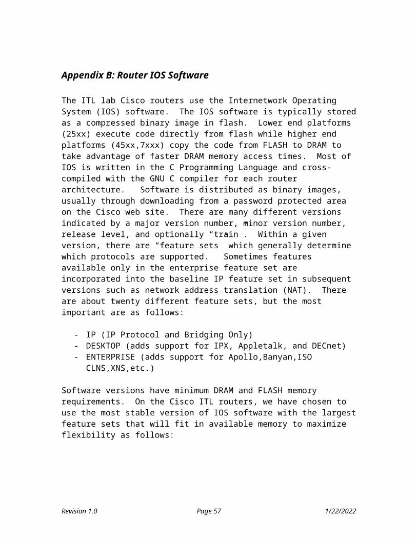
These utilities can be found on the accompanying project CD-ROM in the “cisinfo” directory. The files are present individually and as a UNIX TAR archive. Note that PERL and EXPECT are prerequisite and it is sometimes necessary to edit the first line of the scripts to provide the proper fully qualified filename for the PERL and EXPECT executables.
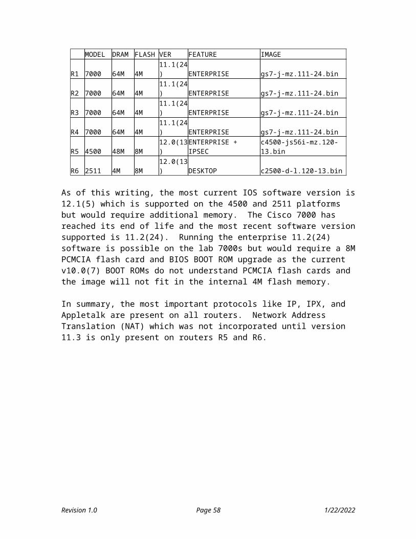
Appendix H: Project CD-ROM
The project CD-ROM contains many files created or downloaded during the course of completing this project. It is a CD-R recordable mode 2 CD-ROM XA disk. It uses a Joliet filesystem and should be readable under Microsoft Windows 95/98/NT/2000. Most original documents were created with Microsoft Word 2000, Excel 2000, PowerPoint 2000 and Visio 2000 Professional which use file extension .DOC, .XLS, .PPT and .VSD respectively. Several Adobe Acrobat portable document format files (.PDF) and hypertext (.HTM) files were derived from the source files. There are also many router configuration files and captured output from text-based router commands stored in files with extension .TXT. The following is a brief description of the CD-ROM directories.
- aclAccess Control List sample lab.
- baselineRudimentary baseline RIP router configuration mentioned in Appendix F.
- basic
Cisco router basics lab that covers inverse telnet, router modes, etc.
- bgpBorder Gateway Protocol lab that covers exterior BGP and GRE tunnel interfaces.
- cisinfoLinux expect and perl scripts mentioned in Appendix G.
- countinfCount-To-Infinity lab that explores this problem with distance vector routing protocols like RIP.
- debugCisco Router Debugging lab that explores router show and debug commands.
- frameFrame-Relay Lab that explores both Frame-Relay emulation and the Split-Horizon problem.
- hardwareSource documents from the paper section on router and switch hardware including many drawings and images of the routers, switches, cables, and other components.
- igpInterior Gateway Protocol lab that explores RIP, OSPF, IGRP, EIGRP, and IS-IS routing protocols.
- iosCisco Internetwork Operating System (IOS) images for use with the lab router hardware plus a Windows-based TFTP server implementation that may be used to download new software to the router flash memory.
- miscAssorted diagrams and notes that did not fit elsewhere.
- multiMultiprotocol lab that explores the IPX and Appletalk protocols.
- paperSource documents for this project paper.
- photosSeveral photographs of the network lab room, routers, switches, cables, connectors, etc., in .JPG format.
- purchaseFiles related to the purchase of the used 2511 router and misc cables and connectors for the lab.
- pw-recoverFiles relating to the router password recovery procedure in appendix D.
- ripRIP protocol lab that explores wide are networking at the Center for Entertainment Studies.
- scratch
Start-From-Scratch lab that has students rebuild the router configurations after they have been mysteriously erased by the instructor.
- slidesPowerpoint slide show presentation given at the project defense, December 8, 2000.
- spantreeSpanning Tree Protocol (802.1D) lab.
- sysadmAn assortment of many public domain programs utilized in CIS5406 (Computer Network and System Administration) used for testing the network. Many are used in the topology discovery lab and are copied here as a convenience.
- topTopology Discovery lab where students use many PC utilities to learn more information about the lab network without password access to the lab routers and switches.
- vintlabThe Virginia Internet Teaching Lab sample lab exercises at the University of Virginia.
- visioComputer network stencils for use with Microsoft Visio 2000 Professional packed in two “.ZIP” files. The Windows program “WinZIP v8.0” program is also included to unpack the archive files.
- vlsmVariable Length Subnet Masking lab which explores VLSM, OSPF, and route summarization.
- wwwFiles related to the World-Wide-Web including source for the initial FSU Computer Science Internet Teaching Lab home page.

Appendix I: Acronyms
ACRONYM DEFINITION
1000baseLX Gigabit Ethernet over singlemode fiber standard1000baseSX Gigabit Ethernet over multimode fiber standard100baseFX Fast Ethernet over fiber standard100baseTX Fast Ethernet over UTP standard802.10 IEEE FDDI trunking protocol (aka SDE)802.1D IEEE Spanning Tree standard for bridges802.1Q IEEE standard ethernet trunking protocolACL Access Control ListARP Address Resoution ProtocolAS Autonomous SystemASN Autonomous System NumberAUI Attachment Unit InterfaceAWG American Wire GaugeBECN Backward Explicit Congestion NotificationBGP Border Gateway Protocol (routing protocol)BRI Basic Rate ISDNCAIDA Cooperative Associate for Internet Data AnalysisCCIE Cisco Certified Internetworking ExpertCDP Cisco Discovery ProtocolCGMP Cisco Group Management ProtocolCIDR Classless Internet Domain RoutingCIM Cisco Interactive MentorCLLI Common Language Location IdentifierCNSA Computer Network and System AdministrationCSU/DSU Channel Service Unit/Data Service UnitDAS Dual Attach StationDDS Digital Data ServiceDLCI Data Link Channel IdentifierDSL Digital Subscriber LineDVMRP Distance Vector Multicast Routing ProtocolEBGP Exterior Border Gateway ProtocolEIA Electronic Industries AllianceEIA568 Commercial Building Telecom Cabling Standard EIGRP Enhanced Interior Gateway Routing ProtocolFDDI Fiber Distributed Data InterfaceFECN Forward Explicit Congestion NotificationFRAD Frame-Relay Access DeviceFXO Foreign Exchange OfficeFXS Foreign Exchange StationH.323 A video and audio videoconferencing standardHSRP Hot Standby Routing ProtocolIAB Internet Activities BoardIBGP Interior Border Gateway ProtocolIEEE Institute of Electrical and Electronics EngineersIETF Internet Engineering Task ForceIGMP Internet Group Management ProtocolIGRP Interior Gateway Routing ProtocolIMUX Inverse Multiplexer
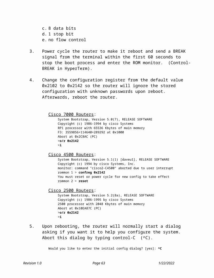
IOS Internetwork Operating SystemIP Internet ProtocolISDN Integrated Services Digital NetworkISIS Intermediate System-Intermediate System (routing protocol)ISL Inter-Switch Link (trunking standard)ITL Internet Teaching LabLAN Local Area NetworkLANE LAN Emulation (ATM)LMI Link Management InterfaceMAN Metropolitan Area NetworkMbps Megabits per secondMII Media Independent InterfaceMM MultiMode (fiber optic cable)OCTET An 8-bit ByteOSPF Open Shortest Path FirstPDF Portable Document FormatPIM Protocol Independent MulticastPOTS Plain Old Telephone ServicePRI Primary Rate ISDNPSTN Public Switched Telephone NetworkPVC Permanent Virtual CircuitQoS Quality of ServiceRFC Request For CommentsRIP Routing Information Protocol (routing protocol)RJ45S 8-Position Modular JackRS232C Asynchronous Serial Communication StandardSAS Single Attach StationSDE Secure Data Exchange (aka 802.10)SM SingleMode (fiber optic cable)SNMP Simple Network Management ProtocolSPF Shortest Path FirstSVC Switched Virtual Circuit (ATM)TCP/IP Transmission Control Protocol/Internet ProtocolTIA Telecommunications Industry AssociationUTP Unshielded Twisted PairVLAN Virtual Local Area NetworkVLSM Variable Length Subnet MaskingVoIP Voice over IPVPN Virtual Private NetworkWAN Wide Area Network