iso 9001:2008 / atex original operating manual ...€¦ · matrix elektronik ag (manufacturer)...
TRANSCRIPT

ISO 9001:2008 / ATEX
Page 1 of 2
Original Operating Manual:Photoelectric sensors with analog output: IRS/IRN/IRD-005-LA*(-OP) IRD-005-LA*-OP Housing M30 IRN-005-LA*-OP
Type IRS-005-LA* IRN-005-LA*-OP IRD-005-LA*-OPTechnical data LA*= Type of analog output. LAV: Voltage output 0 ... 10V.
LAI: current loop output 0mA ... 20mA. LA4: current loop output 4mA ... 20mAType of Ex protection Gas, according to 2014/34/EU NONE II 3(2)G Ex nA [op is Gb] IIB T4 Gc II 2(1)G Ex d [op is Ga] IIC T6 GbType of Ex protection Dust, according to 2014/34/EU NONE II 3(2)D Ex tc [op is Db] IIIA II 2(1)D Ex tb [op is Da] IIIB
T135°C Dc IP67 T100°C Db IP67For use in Ex Zones NONE Zones (1), 2, and (21), 22 Zones (0),1,2 and (20),21,22Output signal range 0.03VDC - 10.5VDC( Ripple:<20mV) or 0.06mA - 21mA or 4mA - 20mAVoltage output, nominal range, on white paper. A4. 80g 5VDC output voltage at a distance of 50cm, adjustableCurrent output, nominal range, on white paper. A4. 80g 10mA output current at a distance of 50cm, adjustable
Light source Infrared 870nmOptical aperture angle approx.12°Maximum optical radiant power NOT LIMITED <=35mW <=15mWMaximum radiant power NOT LIMITED <=5mW/mm2 <=5mW/mm2
Response time 5ms (faster responde time, on request)Power up delay time 500msSupply voltage 24VDC +-10%, Um = maximum 30VDCIntrinsic current consumption max. 60mAMaximum power dissipation 1.6WOutput type, voltage, IR*-005-LAV(-OP) PNP, output impedance appr. 25� , RLoad: 2k� to 1M�Output type, current, IR*-005-LAI/LA4(-OP) NPN, output impedance appr. 500� , RLoad: 0� to 100�Disable-Input, only types IR*-005-LA*(-OP)-S259 PNP compatible, Ri 10k�Housing M30, brass Ms 58, nickel plated (optional stainless steel 1.4404, types: IR*-005-A**(-OP)-S224Enclosure rating, according to EN 60529 IP 65 IP 67 IP67Ambient working temperature range Tamb -20°C up to +50°CStorage temperature range -20°C ... +70°CRelative humidity 15% ... 80%Vibration and shock resistance Vibration: 30g over 20Hz to 2kHz. Shock: 100g for 3msPollution degree, according to EN 60664-1:2007 4Device designation, according to EN 60947-5-2 R3A30AP1Connection cable 3+PE x 0,5mm2,TPU, shielded, leads numbering marked, oil resistant cable for trailing, L: 3mConnection cable, types IR*-005-LA*(-OP)-S259 4+PE x 0,5mm2,TPU, shielded, leads numbering marked, oil resistant cable for trailing, L: 3mSocket, IRS/IRN-005-LA*(-OP)-S099 Male connector M12, Lumberg RSF 5, 5-leadsAccessories, all devices - 2x nuts M30 (or 1 clamp on demand)Accessories, only IRD/IRN-005-LA*-OP - 1x Spare safety screw with packing ring for potentiometer sealingAccessories, only IRN-005-LA*-OP-S099 - 1x Safety lock device, mount at the cable connection, for locking the connection
- 1x Warning plate "Do not open/close when supply voltage connected"- 1x Protection cap for the sensor socket
Accessories, not included, only IRS/IRN-*-S099 - Single ended cordset, types RKTS 5-298/xx or RKWTH 5-298/xx, LumbergAccessories, not included, all types - Additional optic, type DL-30: For range extensionOptions - Cable length: Up to maximum 100m. Designation: IR*-005-LA*(-OP)/K:100m
- IRS/IRN-005-LA*(-OP)-S099: Male connector M12: Lumberg RSF-5, 5 pins- IRS/IRN-005-LA*(-OP)-S110: With additional optic DL30 and special reflector- IRS/IRN-005-LA*(-OP)-S155: Response time = 1.5ms- IRS/IRN-005-LA*(-OP)-S193: Replacement for series IRS-U-5A/I-GF, for applications with
fibre optics series ....Y1.... (Special adoption)-IRN/IRD-005-LA*(-OP)-S224: Housing stainless steel 1.4404 / 316L-IR*-005-LA*(-OP)-S259: With emitter disable input (DI)
• Also for using with different certificated fibre optics• IRD: ATEX and IECEx certificated• Types IRD: For use in Ex Zones (0),1, 2, (20), 21, 22• Types IRN: For use in Ex Zones (1), 2, (21), 22• With voltage or current loop output available• Applicable for range measurement or position detection• Applicable with glass fibre optics
II 2(1)GII 2(1)D
0158
ATEX-Kennzeichnung:II 3(2)G Ex nA [op is Gb] IIB T4 Gc, II 3(2)D Ex tc [op is Db] IIIA T135°C Dc IP67
IECEx designationEx d [op is Ga] IIC T6 GbEx tb [op is Da] IIIB T100°C Db IP67
IECEx BVS 14.0108X
IRD
-005
-LAx
-OP-
IEC
EX_e
2,20
16-1
2-29
/HB
Output diagram(measured on white paper, 80g, 20cm x 30cm)Potentiometer on MINUMUM & MAXIMUM
Function and LED indication
Light beam free Light beam interrupted
Light barrierwith fibre optic
Proximity switch
No light detected. Output=OFF, LED=OFF
Proximity switchwith fibre optic
Wiring and connection +24VDC
Output
0V (-)
R 500�A
0.06-21mA(4-20mA)
IR*-005-LAI/LA4I-Out
+24VDC
Output
0V (-)
The brightness of the LED and theoutput level, is dependant on thequantity of the detected light.
Light barrierwith fibre optic
Proximity switchwith fibre optic
Proximity switch
R 25�PNP=OFF
V0.03-10.5VDC
IR*-005-LAVV-Out
4
6
8
10
12
14
16
18
2 0
5 15 2 5 3 5 4 5 55 6 5 75 8 5 9 5 10 5 115 12 5 13 5Distanz in cm
Iout
in
mA
Vou
t in
VD
C/2
MAXMIN
Mat
rix E
lekt
roni
k AG
(Man
ufac
ture
r)Ti
ppke
mpe
r - M
atrix
Gm
bHK
irchw
eg 2
4 C
H-5
42O
Ehr
endi
ngen
Mee
gene
r Str.
43
D
-514
91 O
vera
thTe
l.:+4
1 56
204
00-2
0
Fax
-29
Tel.:
+49
2206
956
6-0
Fax
-19
info
@m
atrix
-ele
ktro
nik.
com
info
@tip
pkem
per-m
atrix
.com
Page 2 of 2
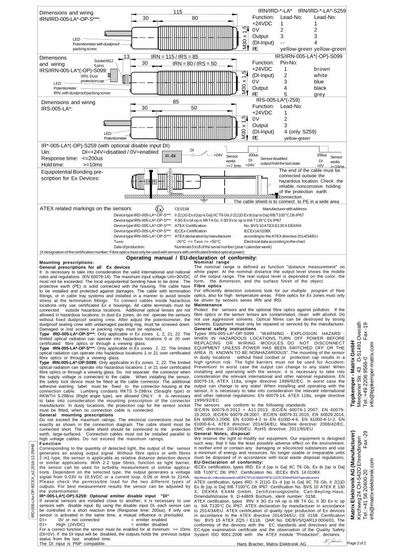
Dimensions and wiringIRS-005-LA*:
855030
M30
x 1
,5
LEDPotentiometer
IR*-005-LA*(-OP)-S259 (with optional disable input DI)Uin: DI=+24V=disabled / 0V=enabledResponse time: <=200usHold time: >=10ms
+24VDI
IR.-DI Sensorworks>=7.5ms
DI=24V
Sensor disabledoutput hold the last state DI
=0V
200us 200us Sensorworks>=10ms
IRS-005-LA*(-259)Function: Lead-No:+24VDC 10V 2Output 3(DI-Input) 4 (only S259)PE yellow-green
Dimensions and wiringIRN/IRD-005-LA*-OP-S***: 8030
M30
x 1
,5
115
LEDPotentiometer with dustproofpacking screw
IRN/IRD-*-LA* IRN/IRD-*-LA*-S259Function: Lead-No: Lead-No:+24VDC 1 10V 2 2Output 3 3(DI-Input) -- 4PE yellow-green yellow-green
LEDPotentiometerIRN: with dustproof packing screw
13Socket M125 pins
Dimensionsand wiringIRS/IRN-005-LA*(-OP)-S099:
IRN = 80 / IRS = 5030
M30
x 1
,5
IRN = 115 / IRS = 85
IRN: Dustprotection cap
IRS/IRN-005-LA*(-OP)-S099Function: Pin-No:+24VDC 1 brown(DI-Input) 2 white0V 3 blueOutput 4 blackPE 5 grey
Equipotential Bonding pre-scription for Ex Devices:
The cable shield is to connect to PE in a wide area
The end of the cable must beconnected outside thehazardous location. Check thereliable, noncorrosive holdingof the protection earthconnection.
ATEX related markings on the sensors CE 0158 Manufacturer with addressDevice type IRD-005-LA*-OP-S***: II 2(1)G Ex d [op is Ga] IIC T6 Gb,II 2(1)D Ex tb [op is Da] IIIB T100°C Db IP67Device type IRN-005-LA*-OP-S***: II 3G Ex nA op is IIB T4 Gc, II 3D Ex tc op is IIIA T135°C Dc IP67Device type IRD-005-LA*-OP-S***: ATEX-Certification No. BVS 10 ATEX E130 X DEKRADevice type IRD-005-LA*-OP-S***: IECEx-Certification IECEx 14.0108XDevice type IRN-005-LA*-OP-S***: ATEX declaration by manufacturer according to the ATEX directive 2014/34/EUTamb: -20°C <= Tamb <= +50°C Electrical data according to the chartDate of production: Numerals 5 to 8 of the serial number (year / calendar week)
(X designation of the certification number: Fibre optics must only be used with sensors with certificated limited optical power)
Nominal rangeThe nominal range is defined as function "distance measurement" onwhite paper. At the nominal distance the output level shows the middleof the output range. The real output level is depended on the color, theform, the dimension, and the surface finish of the object.Fibre opticsFor efficiently detection solutions look for our multiple program of fibreoptics, also for high temperature areas. Fibre optics for Ex zones must onlybe driven by sensors series IRN and IRD.MaintenanceProtect the sensors and the optional fibre optics against pollution. If thefibre optics or the sensor lenses are contaminated, clean with alcohol. Donot use aggressive solvents. Optical fibres can be destroyed by strongsolvents. Equipment must only be repaired or serviced by the manufacturer.General safety instructionsTypes IRN-005-LA*-OP-S099 : "WARNING - EXPLOSION HAZARD -WHEN IN HAZARDOUS LOCATIONS, TURN OFF POWER BEFOREREPLACING OR WIRING MODULES. DO NOT DISCONNECTEQUIPMENT UNLESS POWER HAS BEEN SWITCHED OFF OR THEAREA IS KNOWN TO BE NONHAZARDOUS". The mounting of the sensorin dusty locations without fixed cordset or protection cap results in ahigh ignition risk. The light barriers must not be used for Accident-Prevention! In worst case the output can change to any state! Wheninstalling and operating with the sensor, it is necessary to take intoconsideration the relevant international and other national regulations: EN60079-14, ATEX 118a, single directive 1999/92/EC. In worst case theoutput can change to any state! When installing and operating with thesensor, it is necessary to take into consideration the relevant internationaland other national regulations: EN 60079-14, ATEX 118a, single directive1999/92/EC.The sensors are conform to the following standards:IEC/EN 60079-0:2012 + A11:2013, IEC/EN 60079-1:2007, EN 60079-15:2010, IEC/EN 60079-28:2007, IEC/EN 60079-31:2010, EN 60529:2014,EN 60950-1:2006; EN 61000-4-2 to EN 61000-4-6, EN 61000-6-1/-2, EN61000-6-4, ATEX directive: 2014/34/EU, Machine directive: 2006/42/EC,EMC directive: 2014/30/EU, RoHS directive: 2011/65/EU.General Notes, disposalWe reserve the right to modify our equipment. Our equipment is designedsuch way, that it has the least possible adverse effect on the environment.It neither emit or contain any damaging or siliconized substances and usea minimum of energy and resources. No longer usable or irreparable unitsmust be disposed of in accordance with local waste disposal regulations.EU-Declaration of conformity:IECEx certification, types IRD: Ex d [op is Ga] IIC T6 Gb, Ex tb [op is Da]IIIB T100°C Db IP67. Certification No. IECEx BVS 14.0108X.http://iecex.iec.ch/iecex/iecexweb.nsf/0/FE79714C0BAEF6F5C1257D7E0044F6A9?opendocumentATEX certification, types IRD: II 2(1)G Ex d [op is Ga] IIC T6 Gb, II 2(1)DEx tb [op is Da] IIIB T100°C Db IP67. Certification No. BVS 10 ATEX E 130X, DEKRA EXAM GmbH, Zerti fizierungsstelle, Carl-Beyling-Haus,Dinendahlstrasse 9, D-44809 Bochum, ident number: 0158.ATEX certification, types IRN: II 3G Ex nA op is IIB T4 Gc, II 3D Ex tc opis IIIA T135°C Dc IP67. ATEX declaration by manufacturer in accordanceto 2014/34/EU. ATEX certification of quality type production of Ex devicesin accordance to the ATEX directive 2014/34/EU, CE 0158. CertificationNo: BVS 15 ATEX ZQS / E118, QAR No. DE/BVS/QAR13.0004/01. Theconformity of the devices with the EC standards and directives and theEC-type examination certificate and the observation of the Quality SafetySystem ISO 9001:2008 with the ATEX module "Production", declares:
Hans Bracher, Matrix Elektronik AG
Mounting prescriptions:General prescriptions for all Ex devicesIt is necessary to take into consideration the valid international and nationalrules and regulations (EN 60079-14). The maximum input voltage Um=30VDCmust not be exceeded. The local equipotential bonding have to be done. Theprotective earth (PE) is solid connected with the housing. The cable haveto be installed and protected against damages. The cable with terminationfittings, or in cable tray systems and installed in a manner to avoid tensilestress at the termination fittings. To connect cables inside hazardouslocations only use certificated Ex e housings. All cable terminals must beconnected outside hazardous locations. Additional optical lenses are notallowed in hazardous locations. In dust Ex zones, do not operate the sensorswithout fixed dustproof sealing crew. After adjust the potentiometer, thedustproof sealing crew with undamaged packing ring, must be screwed down.Damaged or lost screws or packing rings must be replaced.Type IRD-005-LA*-OP-S***: Only applicable in Ex zones 1, 2, 21, 22. Thelimited optical radiation can operate into hazardous locations 0 or 20 overcertificated fibre optics or through a viewing glass.Type IRN-005-LA*-OP-S***: Only applicable in Ex zones 2, 22. The limitedoptical radiation can operate into hazardous locations 1 or 21 over certificatedfibre optics or through a viewing glass.Type IRN-005-LA*-OP-S099: Only applicable in Ex zones 2, 22. The limitedoptical radiation can operate into hazardous locations 1 or 21 over certificatedfibre optics or through a viewing glass. Do not separate the connector whenthe supply voltage is connected to the cable. When installing the sensor,the safety lock device must be fitted at the cable connector. The additionaladhesive warning label must be fixed to the connector housing at theconnection cable. Lumberg cordsets RKTS 5-298/xx (Straight type) orRKWTH 5-298/xx (Right angle type), are allowed ONLY. It is necessaryto take into consideration the mounting prescription of the connectormanufacturer. In dusty locations, the protection cap for the sensor socketmust be fitted, when no connection cable is connected.General mounting prescriptionsDo not exceed the maximum ratings. The electrical connections must beexactly as shown in the connection diagram. The cable shield must beconnected short. The cable shield should be connected to the protectionearth, large-surfaced. Connection cables must not be installed parallel tohigh voltage cables. Do not exceed the maximum ratings.Funct ionCorresponding to the quantity of detected light, the output of the sensorgenerates an analog output signal. Without fibre optics or with fibres2 in1 type, the sensor is applicable as relative distance detection deviceor similar applications. With 2-2 type fibres, function as light barrier,the sensor can be used for turbidity measurement or similar applica-tions. Dependent on the selected type, the output generates a voltagesignal from 0.03V to 10.5VDC or a current loop, 0.06 or 4mA to 21mA.Please check the permissible load for the two different types ofoutputs. For best measurement results the sensor can be adjusted bythe potentiometer.IR*-005-LA*(-OP)-S259: Optional emitter disable input "DI"If several sensors are installed close to another, it is necessary to usesensors with disable input. By using the disable input DI, each sensor canbe controlled in a short reaction time (Response time: 200us). If only onesensor is activated in the same time, a mutual influence is precluded.DI= 0V or not connected = emitter enabledDI= High (24VDC) = emitter disabledFor a correct function the sensor must be enabled for at minimum >= 10ms(DI=0V). If the DI input will be disabled, the outputs holds the previous outputstatus from the last enabled time.The DI input is PNP compatible.
Operating manual / EU-declaration of conformity:
IRD
-005
-LAx
-OP-
IEC
EX_e
2,20
16-1
2-29
/HB