is 6752 (1991): code of practice for magnetic particle
TRANSCRIPT
Disclosure to Promote the Right To Information
Whereas the Parliament of India has set out to provide a practical regime of right to information for citizens to secure access to information under the control of public authorities, in order to promote transparency and accountability in the working of every public authority, and whereas the attached publication of the Bureau of Indian Standards is of particular interest to the public, particularly disadvantaged communities and those engaged in the pursuit of education and knowledge, the attached public safety standard is made available to promote the timely dissemination of this information in an accurate manner to the public.
इंटरनेट मानक
“!ान $ एक न' भारत का +नम-ण”Satyanarayan Gangaram Pitroda
“Invent a New India Using Knowledge”
“प0रा1 को छोड न' 5 तरफ”Jawaharlal Nehru
“Step Out From the Old to the New”
“जान1 का अ+धकार, जी1 का अ+धकार”Mazdoor Kisan Shakti Sangathan
“The Right to Information, The Right to Live”
“!ान एक ऐसा खजाना > जो कभी च0राया नहB जा सकता है”Bhartṛhari—Nītiśatakam
“Knowledge is such a treasure which cannot be stolen”
“Invent a New India Using Knowledge”
है”ह”ह
IS 6752 (1991): Code of practice for magnetic particle flawdetection of ferrous pipes and tubes [MTD 21:Non-Destructive Testing]

IS 6752 : 1991
CODE OF PRACTICE FOR MAGNETIC PARTICLE FLAWDETECTION OF FERROUS
PIPES AND TUBES
( First Revision )
UDC 621’643’2 [ 669’14 ] : 621’179’14
Jub 1991
@ BIS 1991
BUREAU OF INDIAN STANDARDS MANAK BHAVAN, 9 BAHADUR SHAH ZAFAR MARG
NEW DELHI 110002
Price Greqp 2
Non-destructive Testing Sectional Committee, MTD 21
FOREWORD
This Indian Standard ( First Revision ) was adopted by -the Bureau of Indian Standards, after the draft finalized by the Non-destructive Testing Sectional Committee had been approved by the Metallurgical Engineering Division Council.
This standard was first published in 1972. The first revision has been prepared taking into account the latest technological developments on the subject. In this revision, the testing equipment, testing procedure and the viewing condition.
more c/&ails have been given about
Magnetic particle flaw detection is a non-destructive method for the detection of flaws at or near the surface of ferro-magnetic materials. This method is being widely used for the detection of flaws at or near the surface of ferrous pipes and tubes required for various types of applications. The use of this code of practice will, it is hoped, ensure uniform practice and assist manufacturers, inspecting authori- ties and users to determine appropriate quality levels for specific types of pipes and tubes.
For the purpose of deciding whether a particular requirement of this standard is complied with, the final value, observed or calculated, expressing the result of a test or analysis, shall be rounded off in accordance with IS 2 : 1960 ‘Rules for rounding off numerical values ( revised )‘. The number of significant places retained in the rounded off value should be this standard.
the same as that of the specified value in
IS 6752 : 1991
Indian Standard
CODE OF PRACTICE FOR MAGNETIC PARTICLE FLAW DETECTION OF FERROUS
PIPES AND TUBES
( First Revision )
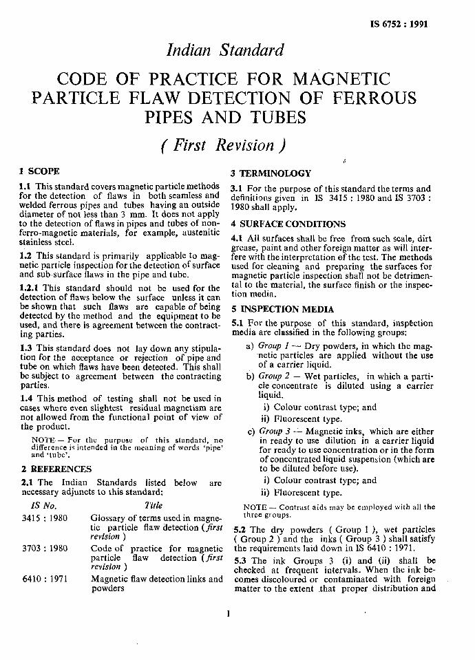
1 SCOPE
1.1 This standard covers magnetic particle methods for the detection of flaws in both seamless and welded ferrous pipes and tubes having an outside diameter of not less than 3 mm. It does not apply to the detection of flaws in pipes and tubes of non- ferro-magnetic materials, for example, austenitic stainless steel.
d
3 TERMINOLOGY
1.2 This standard is primarily applicable to mag- netic particle inspection for the detection of surface and sub.surface flaws in the pipe and tube.
1.2.1 This standard should not be used for the detection of flaws below the surface unless it can be shown that such flaws are capable of being detected by the method and the equipment to be used, and there is agreement between the contract- ing parties.
1.3 This standard does not lay down any stipula- tion for the acceptance or rejection of pipe and tube on which flaws have been detected. This shall be subject to agreement between the contracting parties.
1.4 This method of testing shall not be used in cases where even slightest residual magnetism are not allowed from the functional point of view of the product.
NOTE.- For the purpose of this standard, no difference is intended in the meaning of words ‘pipe’ and ‘tube’.
2 REFERENCES
2.1 The Indian Standards listed below are necessary adjuncts to this standard:
IS No. Title
3415 : 1980 Glossary of terms used in magne- tic particle flaw detection (fifirsr revision )
3703 : 1980 Code of practice for magnetic particle flaw detection (first revision )
6410 : 1971 Magnetic flaw detection links and powders
3.1 For the purpose of this standard the terms and definitions given in IS 3415 : 1980 and IS 3703 : 1980 shall apply.
4 SURFACE CONDITIONS
4.1 All surfaces shall be free from such scale, dirt grease, paint and other foreign matter as will inter- fere with the interpretation of the test. The methods used for cleaning and preparing the surfaces for magnetic particle inspection shall not be detrimen- tal to the material, the surface finish or the inspec- tion media.
5 INSPECTION MEDIA
5.1 For the purpose of this standard, inspection media are classified in the following groups:
a) Group 1 - Dry powders, in which the mag- netic particles are applied without the use of a carrier liquid,
b) Group 2 - Wet particles, in which a parti- cle concentrate is diluted using a carrier liquid.
i) Colour contrast type; and ii) Fluorescent type.
c) Group 3 - Magnetic inks, which are either in ready to use dilution in a carrier liquid for ready to use concentration or in the form of concentrated liquid suspension (which are to be diluted before use). i) Colour contrast type; and
ii) Fluorescent type.
NOTE - Contrast aids may be employed with all the three gt oups.
5.2 The dry powders ( Group 1 ), wet particles ( Group 2 ) and the inks ( Group 3 ) shall satisfy the requirements laid down in IS 6410 : 1971.
5.3 The ink Groups 3 (i) and (ii) shall be checked at frequent intervals. When the ink be- comes discoloured or contaminated with foreign matter to the extent that proper distribution and
I
IS 6752 : 1991
concentration of the ink or the intensity, character or definition of the magnetic particles are impaired, it shall be discarded and replaced with fresh ink,
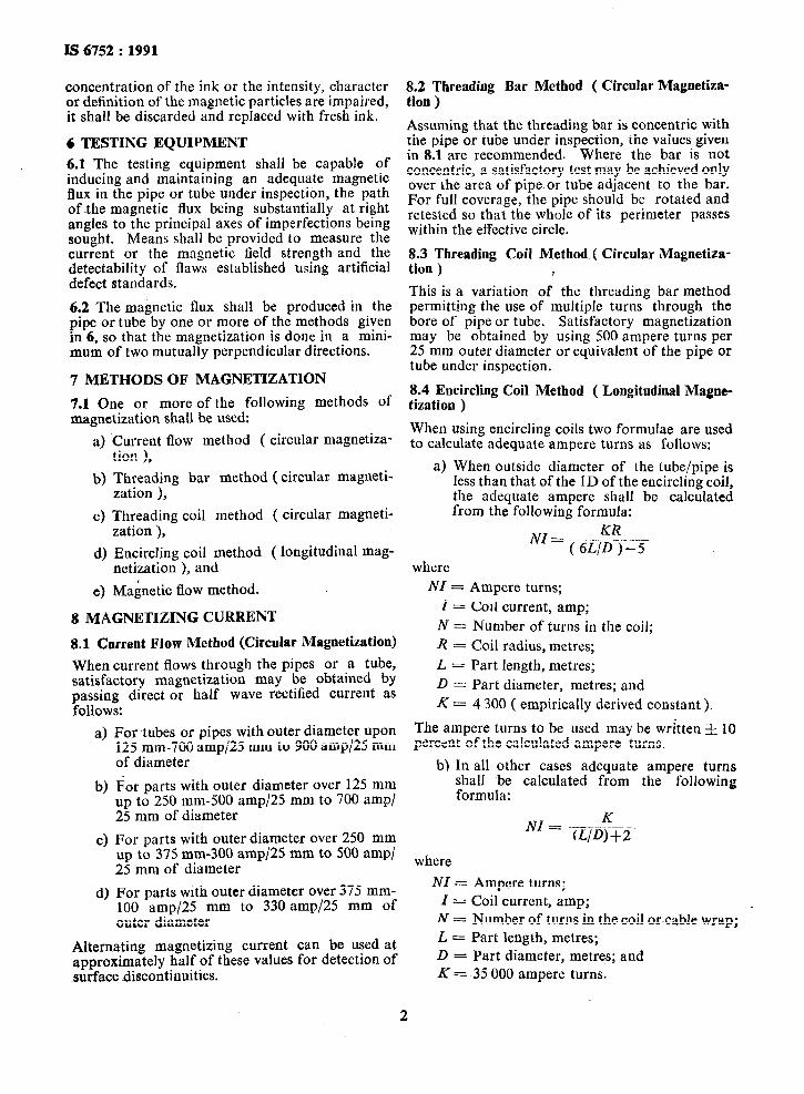
6 TESTING EQUIPMENT
6.1 The testing equipment shall be capable of inducing and maintaining an adequate magnetic flux in the pipe or tube under inspection, the path of the magnetic flux being substantially at right angles to the principal axes of imperfections being sought. Means shall be provided to measure the current or the magnetic field strength and the detectability of flaws established using artificial defect standards.
6.2 The magnetic flux shall be produced in the pipe or tube by one or more of the methods given in 6, so that the magnetization is done in a mini- mum of two mutually perpendicular directions.
7 METHODS OF MAGNETIZATION
7.1 One or more of the following methods of magnetization shall be used:
a) Current flow method ( circular magnetiza- tion ),
b) Threading bar method ( circular magneti- zation ),
c) Threading coil method ( circular magneti- zation ),
d) Encircling coil method ( longitudinal mag- netization ), and
e) Magnetic flow method.
8 MAGNETIZING CURRENT
8.1 Current Flow Method (Circular Magnetization)
When current flows through the pipes or a tube, satisfactory magnetization may be obtained by passing direct or half wave rectified current as follows:
a)
b)
cl
4
For tubes or pipes with outer diameter upon 125 mm-700 amp/25 mm to 900 amp/25 mm of diameter
For parts with outer diameter over 125 mm up to 250 mm-500 amp/25 mm to 700 amp/ 25 mm of diameter
For parts with outer diameter over 250 mm up to 375 mm-300 amp/25 mm to 500 amp/ 25 mm of diameter
For parts with outer diameter over 375 mm- 100 amp/25 mm to 330 amp/25 mm of outer diameter
Alternating magnetizing current can be used at approximately half of these values for detection of surface discontinuities.
8.2 Threading Bar ~Method ( Circular -Magnetiza- tion )
Assuming that the threading bar is concentric with the pipe or tube under inspection, the values given in 8.1 are recommended. Where the bar is not concentric, a satisfactory test may be achieved only over the area of pipe or tube adjacent to the bar. For full coverage, the pipe should be rotated and retested so that the whole of its perimeter passes within the effective circle.
8.3 Threading Coil Method ( Circular Magnetiza- tion ) ii
This is a variation of the threading bar method permitting the use of multiple turns through the bore of pipe or tube. Satisfactory magnetization may be obtained by using 500 ampere turns per 25 mm outer diameter or equivalent of the pipe or tube under inspection.
8.4 Encircling Coil Method ( Longitudinal Magne- tization )
When using encircling coils two formulae are used to calculate adequate ampere turns as follows:
a) When outside diameter of the tube/pipe is less than that of the ID of the encircling coil, the adequate ampere shall be calculated from the following formula:
ivz =.(‘6L;)_-I
where
NZ = Ampere turns; Z = Coil current, amp;
N = Number of turns in the coil; R = Coil radius, metres; L = Part length, metres; D = Part diameter, metres; and K = 4 300 ( empirically derived constant ).
The ampere turns to be used may be written & 10 percent of the calculated ampere turns.
b) In all other cases adequate ampere turns shall be calculated from the following formula:
where
_NZ = Ampere turns; Z = Coil current, amp;
N = Number of turns in the coil orcable wrap; L = Part length, metres; D = Part diameter, metres; and K = 35 000 ampere turns.
2
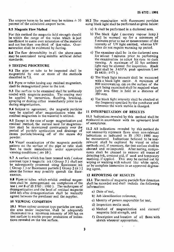
The ampere turns to be used may be written f 10 percent of the calculated ampere turns.
8.5 Magentic Flow Method
For this method the magnetic field strength should be within the range of the value which is just insufficient to cause over saturation of the material and not less than one-third of that value. Over- saturation shall be evidenced by furring.
8.6 The flaw detectability in all the above cases may be ascertained using suitable artificial defect standards.
9 TESTING PROCEDURE
9.1 The pipe or tube to be inspected shall be magnetized by one or more of the methods described in 7.1.
9.2 Pipes or tubes having any residual magnetism, shall be demagnetized prior to the test.
9.3 The surface to be examined shall be uniformly coated with magnetic particles. The coating may be applied by immersion, flooding, brushing, spraying or dusting either immediately prior to or during magnetization.
9.4 Subject to agreement, the magnetic particles may be applied after magnetization when the residual magnetism in the material is utilized.
9.5 Except in the case of surge magnetization and residual method, the current used for magnetiza- tion shall be maintained continuously over the period of particle application and drainage of excess particle/blowing off of the excess dry powder.
9.6 Visual examination of the magnetic particle pattern on the surface of the pipe or tube shall then be made immediately under appropriate viewing conditions ( see 10 ).
9.7 A surface which has been treated with ( colour contrast type ) magnetic ink ( Group 3 ) shaH not be subsequently processed using fluorescent ink ( Group 3 ) or fluorescent particle [ Group 2 (ii ) ] since the former may possibly quench the fluor- escence.
9.8 Pipes or tubes which exhibit residual magne- tism shall be demagentized on completion of the test ( see 8 of IS 3703 : 1980 ). The techniques of demagnetization and the level of residual magnetic field left after demagnetization shall be mutually agreed between the purchaser and the supplier.
lo VIEWING CONDITION
10.1 When colour contrast type particles are used, the area under inspection shall be adequately illuminated to a minimum intensity of 500 lux on test surface to enable proper evaluation of indica- tions revealed on the test surface.
IS 6752 : 1991
10.2 The examination with fluorescent particles using ~black light shall be performed as given below:
4 b)
c)
4
4
It shall be performed in a darkened area.
The black light ( mercury vapour lamp ) shall be warmed up for a minimum of 5 minutes prior to use or measurement of the intensity of UV light emitted, whereas UV tubes do not require warming up period.
The examiner shall be in the darkened area for atleast 5 minutes prior to performing the examination to adapt his eyes to dark viewing. A maximum of 32 lux ambient light may be allowed for inspection. Black light shallbe 3 650°A peak spectrum ( see IS 6410: 1971 ).
The black light intensity shall be measured with a black light meter. A minimum of 800 microwatt/s+ cm on the surface of the part being examined shall be required when light lens filter is held at a distance of 380 mm.
The black light intensity shall be checked at the frequency specified by the purchaser and whenever the work station is changed,
11 INTERPRETATION OF RESULTS
11.1 Indications revealed by this method shall be evaluated in accordance with an agreement level of acceptance.
11.2 All indications revealed by this method do not necessarily represent flaws since non-relevant indications as indicated in IS 3703 : 1980 may be encountered. Indications believed to be non- relevant shall be explored by visual or other methods and, if necessary, the test surface shall be cleaned and re-inspected. After testing, compo- nents shall be cleaned to remove all traces of detecting ink, contrast aid, if used and temporary marking, if applied. This may be carried out by wiping or washing with solvent like white spirit, or by complete immersion in an approved degreas- ing agent.
12 REPORTING OF RESULTS
12.1 The results of magnetic particle flaw detection shall be recorded and shall include the following information:
4 b! c) 4 d
f )
Date of test,
Job identification reference, Identity of person responsible for test, Inspection media used,
Method of magnetization and current/ magnetic field strength, and
Description and location of all flaws with sketch wherever appropriate.
3
Standard Mark
The use of the Standard Mark is governed by the provisions of the Bureuu of Indian Standards Act, 1986 and the Rules and Regulations made thereunder. The Standard Mark on products covered by an Indian Standard conveys the assurance that they have been produced to comply with the requirements of that standard under a well defined system~of inspection, testing and quality control which is devised and supervised by BIS and operated by the producer. Standard marked products are also continuously checked by BIS for conformity to that standard as a further safeguard. Details of conditions under which a licence for the use of the Standard Mark may be granted to manufacturers or producers may be obtained from the Bureau of Indian Standards.
Boreau of Indian Standards
BIS is a statutory institution established under the Bureau of Indian Standards Act, 1986 to promote harmonious development of the activities of standardization, marking and quality certification of goods and attending to connected matters in the country. _,
c
Copyright _,J ’
BIS has the copyright of all ,its publications. No part of these publications may be ‘reproduced in any form without the prior permission in writing of BIS. This does not preclude the free use, in the course of implementing the standard, of necessary details, such as symbols and sizes, type or grade designations. Enquiries relating to copyright be addressed to the Director ( Publications ), BIS.
Revision of Indfan Standards
Indian Standards are reviewed periodically and revised, when necessary and amendments, if any, are issued from time to time. Users of Indian Standards should ascertain that they are in possession of the latest amendments or edition. Comments on this Indian Standard may be sent to BIS giving the following reference:
Dot : No. MTD 21 ( 3433 )
Amendmenta Issued Since Pablicatioo
Amend No. Date of Issue Text At&ted
BUREAU OF INDIAN STANDARDS
Headquarters :
Manak Bhavan, 9 Bahadur Shah Zafar Marg, New Delhi 110002 Telephones : 331 01 31, 331 13 75 Telegrams : Manaksanstha
( Common to all Offices’ )
. Regional Offices : Telephono
i Central : Manak Bhavan, 9 Bahadur Shah Zafar Marg 33101 31 NEW DELHI 110002 33113 75
Eastern : l/l4 C. I. T. Scheme VII M, V. I. P. Road, Maniktola CALCUTTA 700054
37 84 62
Northern : SC0 445-446, Sector 35-C, CHANDIGARH 160036 53 38 43
Southern : C. I. T. Campus, IV Cross Road, MADRAS 600113 235 02 16
Western : Manakalaya, E9 MIDC, Marol, Andheri ( East ) BOMBAY 400093
6 32 92 95
Branches : AHMADABAD. BANGALORE. BHOPAL. BHWBANESHWAR. COIMBATORE. FARIDABAD. GHAZIABAD. GUWAHATI. HYDERABAD. JAIPUR. KANPUR. PATNA. THIRUVANANTHAPURAM.
Printed at Printvoll Printers. Delhi, India