is: 2502 - 1963 zedian standardxa.yimg.com/kq/groups/2173108/68525129/name/2502.pdf · is : 2502...
TRANSCRIPT

IS: 2502 - 1963 ( Renflirmed 1990 )
Zedian Standard
CODE OF I?RACTICE FOR BENDING AND FIXING OF BARS FOR
CONCRETE REINFORCEMENT
Twelfth Reprint MARCH 1998
Gr 7
UIX 691.87-42:693.554
@ Copyright 1964
BUREAU OF INDIAN STANDARDS MANAK BHA-VAN, 9 BAHADUR SHAH ZAFAR MARG
NEW DELHI 110002
May 1964
1

IS:2!502-1963 (lbAmTlled 1990)
Indian Standard
CODE OF l?RACTICE FOR BENDING AND FIXING OF BARS FOR
CONCRETE REINFORCEMENT
Joint Sectional Committee for Concrete Reinforcement, BSMDC 8
Chaitwan Representing
SHRI C. P. MALIK National Buildings Construction Corporation Ltd, New Delhi
SHRI I<. F. ANTIA RI. N. Dastur & Co (qivate) Ltd,
SHRI n. f?. ~HATTACH.~IPJEE I.R.C. Weldmesh Ltd, Calcutta
SHRI N. (;. DEWAN Central Public Works ‘Department
SHRI Ii. C. RAJACOP.\L.\N (.IItrrnate) SHR~ 1'. D0RaSW4hlY Iron & Steel Control, Calcutta
SHRI Ii. R. N. SW\nrY (.4ttPvvntr)
Calcutta
SHRI F,. N. GUPTA The Steel Re-rolling Mills Association of India,
Calcutta
SllRl P. I<. GLll’TE National Metallurgical Laborator) (CSIR),
Jamshedpur
SHRI M. A. HAFE& National Buildings Organization (Ministry of \\‘orks, Housing Cp: Rehabilitation)
ASSISTANT DIRECTOR (DE-
SIGNS) (ilIlwnale) SHRI HARC~~AND S1NC.H Indian Steel & Wire Products Ltd, Jamshedpur
SliRI R. R. I<.4PLISH (ffb’?tntr) JOINT DIRECTOR STANDARDS Railway Board (3linistry of Railways)
(B&S), RESEARCH, DESIGNS &
STANDARDS ORGANIZATION
SHRI Ii. N. KUDALKAR Gammon India Ltd, Bombay
DR A. Ii. M~LL~K Hindustan Steel Ltd, Rourkela
DR A. IWAN (AZtrmate) (Continued on page 2)
BUREAU OF INDIAN STANDARDS hlANAK BHAVAN, 9 D.+H.-\DUR SHAH Z.AFAR MARG
NE\V DELHI llOOO?
1

L.
IS:2502 -1963
(Continued /mm page 1)
Meuhers Representing
Sml S. C. ~~.~zLJMD.~R Cannon Dunkerley t Co Ltd, New Delhi &RI S. K. C;UHI THAKURTA (AIlematc)
SHRl N. H. M0HU.u The Concre?e Association of India, Bombay SI~RI C. J>. N. JYI’NL;.\R (.lltcmate)
SHWI 5121. 1’. N.\GAH!5IIETIi Roads Wing, Ministry of Transport & Com-
munications S~HI G. V~NKATIXILU (_+fEfcrhu/r)
SHRI E. I<. N. NAMBIAR Directorate General of Supplies C Disposals (Ministry of. Economic & Defence Co-prdina- tion)
Dr. I. C. DOS M. PAIS Cl:nDOU Central Water C Power Commission (Ministry of Irrigation C Power)
SHRI Y. I<. MURTHY (Allevtwt~) SHRI Il. I<. PANTHAKY Hindustan Construction Co Ltd, Bombay SARI RAD~IEY SWAM Engineer-in-Chief’s Branch, Army Headquarters PROF G. S. R~MASWAMY Central Building Research Institute &SIR),
Roorkee SHRI IC. SIVA PRASAP (AIfrmaie)
SECRETARY Central Board of Irrigation & Power, New Delhi SHRI V. M. TA~ATI Spunpipe & Construction Co (Baroda) Ltd,
Baroda SHRI Y. 1,. TANDON Railway Testing & Research Centre (Railway
Board), Lucknow SHRX N. M. THADANI Sahu Cement Service, New Delhi Dw H. C. VISVESVARAYA, Director, IS1 (Rx-@cio Member)
Deputy Director (Bldg)
Secretary
SHRI A. PRITHIVX RAJ Extra .4seistant Director (Bldg), IS1
2
I§ : 2502 - 1963
Indian Standard
CODE OF PRAQTICE FOR BENDING AND FIXING OF BARS FOR
CONCRETE REINFORCEMENT
0. FOREWORD
0.1 This Indian Standard was adopted by the Inclinn Standards Institution on 21 September 1963, after the draft finalized by the joint SLctiolrnl Committee for Concrete lieinforctment lrnd been approvc~tl by the Building Division Council and th[* Structnral and Mdals Di\,ision Council.
0.2 This standard is prepared with a view to assisting dcsigncrs, cnginc~s and contractors in drawing up precise bcntling schedules for reinforcement used in reinforced concrete construction, and also in the fising of rcinforcc- ment. Though, it is well appreciated that much of time and effort can bc saved on the site if rational dimensions for shaping the bars are supplied to the bar benders; different practices have been followed hitherto in drawing up the bar bending schedule. It is attempted in this standard to unify the various practices followed and to rationalize the bending schcdulc to correspond with metric scrics of rcinforcemcnt.
0.3 Rar bending is an operation which requires adequate -supervision, skilled workmanship and cffic’ent equipment; and any attempt to carry out the work with unskilled la b our and inefficient tools will undoubtedly result in unsatisfactory work. In view of this, certain recommended methods of bar bending are also included in this standard.
0.4 Though. this standard is primarily intended for the preparation of bending schedule for reinforced concrete work, it may also be generally adopted for mild steel reinforcement used in prestresscd concrete work.
0.5 The Sectional Committee responsible for the preparation of this stan- dard has taken into consideration the views of producers, consumers and technologists and has related the standard to the manufacturing and trade practices followed in the country in this,field. Due weightage has also been given to the need for international co-ordination among stan- dards prevailing in different countries of the world. These considerations led the Committee to derive assistance from the following Publications:
DRAFT REVISION OF B.S. 1478: 1948 BENDING DIMENSIONS AND SCHEDULING OF BARS FOR THE REINFORCEMENT OF CONCRETE. British Standards Institution.
3

IS : 2502 - 1963
AC1 315-1951 MANUAL OF STANDARD PRAC-CICE FOR DETAILING REINFORCED CONCRETE STRUCTURES. American Concrete Institute.
0.6 Wherever a reference to any Indian Standard appears in this code, it shall be taken as a reference to its latest version.
0.7 This standard is intended chiefly to cover the technical provisions relating to bending and fixing of bars for concrete reinforcement, and it does not include all the necessary provisions of a contract.
1. SCOPE
1.1 This standard covers symbols and approximate dimensions of bends, and bending and fixing procedures for reinforcement,
1.2 The dimensioning and bending of bars specified in this standard applies principally to reinforcement bars conforming to*IS: 432-1960 Specification for Mil(i Steel and Medium Tensile Steel Bars and Hard-Drawn Steel Wire for Concrete Reinforcement (Revised). They may also be used in the case of bars conforming to the following specifications with such modifications as may be found necessary:
tIS: 1139-1959 HOT ROLLED MILD STEEL AND MEDIUM TENSILE STEEL DEFORMED BARS FOR CONCRETE REINFORCEMENT
tlS: 1$%6-1961 COLD-TWIS~V% STEEL BARS FOR CONCRETE REINFOR- CEMENT
2. FORM OF SCHEDULE
2.1 In conjunction with the requirements of this code, standard form of reinforcement schedule as shown in Table I shall be used for purposes of detailing reinforcement in concrete work.
3. BEND DIMENSIONS AND SYMBOLS
3.1 General - The dimensions of bends should be so given that a minimum amount of calculation is necessary for marking off bars and setting the machine and stops. The dimensioning procedure shown in Fig. 1 and Tables II to IX (see p_ 7 to 14) should be adopted as far as possible.
3.1.1 Where no indication is given to the contrary, the angle between the portions of a bar at a bend shall be assumed to be a right angle. Bending dimensions in which angles are expressed in degrees should be avoided as far as possible. When bending b.ars of large diameter, care should be taken to ensure that the overall length of the bent bar does not excee.d the theoretical or calculated length.
3.1.2 When the shape of any bent bar is other than those covered by Tables III to IX but is made up by combining two or more shapes, the
*Since second revision issued as IS : 432 ( Parr I )-I966 and IS : 432 ( Part II )-1966. )Since rex ised.
4

IS : 2502 -1963
TABLE I ST.QNDARD FORM OF REINFORCEMENT SCHED1JL.E
(Clausz 2.1)
Schedule Number
LOCA- MARK TION DESIC-
N.4TION
(1) ( (2)
Column C4 4R 25N
SIZE NUMBER 1 NUMBER AND
TYPE
--
(31 1 (4)
11s roond 5
I I
4 25 mm
TOTAL NUMBER
(6)
20
LENGTH SHAPE (.iLL DIMENSIONS
ARb IN ACCORDANCE WITH Tfl1.S STANDARD UNLESS
OTHERWISE STATED)
(7) (8)
3000mm Straight
NOTE 1 -The recommended widths of the above columns are reading from left to right 25. 20, 15. 15, 15, 1’5, IS and 75 mm. The 75 mm dimension may be reduced to 70 mm for paper sizes other than l A4. Adequate margin should be provided on either side, the left-hand margin being not less than 15 mm. The length of the form should not generally exceed that of *A4 size.
NOTE 2 - In co1 2, the bar identification that will be put on the labels attached to the bars shall appear. It should be simple. The first number in the mark designation refers to the number of identical bars in similar locations in the same section of a given member, and the letter R refers to round bars, the figure that follows the letter R represents the diameter or the nominal size of the bar in millimetres and N represents the identification number of the bar/bars given consecutively.
NOTE 3 - In co1 3. the quality and basic shape of the reinforcement bar shall be specified.
*A4 size is 210 x 297 mm.
bending dimensions shall be measured as shown for appropriate standard shapes. Where the shape of a bent bar is such that it cannot be obtained even by combining two or more standard shapes, the bars shall be fully dimensioned in the schedule and also the method of measuring the bending dimensions shall be indicated in the schedule; but such special shapes should be avoided as far as possible.
3.2 Bends and Hooks FGrming End Anchorages 3.2.1 Dimensions of Bends ad Hooks - Unless otherwise indicated in
the schedule, a semicircular hook or a bend forming an anchorage to a bar shall be bent with an internal radius in accordance with Fig. 1A and Fig. IB, respectively. The hook and bend allowances shall be in accordance with Table II.
5

IS : 2502 - 1963
4d MIN
H
IA Hook I6 Bend
NoTE 1 --k has a value of 2, in the case of mild steel conforming to*IS: 432- 1960 Spccilication for Mild Steel and Medium Tensile Steel Bars and Hard-Drawn Steel Wire for Concrctc Keinforcement (Kevised) or tIS: 1139-1959 Specification for Hot Rolled Mild Steel and Medium Tensile Steel Deformed Bars for Concrete Rcinforccment; 3, in tho case of medium tensile steel conforming to*IS: 432-1960 ortlS: 1139-1959; and 4, in the case of cold worked steel conforming totIS: 1786- 1961 Specification for Cold Twisted Steel Bars for Concrete Heinlorccment. In the cast of bars above 25 mm, however, it is desirable to increase the k valnc to 3, 4 and 6 respectively.
NOTE 2 -H and B refer to hook allowance and bend allowance respectively (see Table II).
FIG. 1 STANDARD HOOK AND BEND
3.8 Binders, Stirrups, Links and the Like-In the case of binders, stirrups, links, etc, the straight portion beyond end of the curve at the end shall be not less than eight times the nominal size of the bar.
4. CURVED BARS
4.1 Bars specified to be formed to radii exceeding those given in Tabiz X (see p. 15) need not be bent, but the required curvature may be obtained during placing.
5. BENDING AND CUTTING TOLERANCES
5.1 Bars shall be bent in accordance with the appropriate dimensions shown in the schedule. Where an overall or an internal dimension of the bent bar is specified, the tolerance, unless otherwise stated, shall be as in Table XI (see p. 15).
5.1.1 Any excess in length of bar supplied over the total of the lengths of the various portions of the bar between bends, including the spccitied tolerances or not, shall be taken up in the end anchorages, or in that portion of the bar which shall be indicated on the schedule. The cutting lengths shall be specified to the next greater ,,vhole 25 mm of the sum of the bending dimensions and allowance.
‘Since second revision issued as IS : 432 ( Part I )-I966 and IS : 432 ( Part 11 )-1966. tSince revised.
6

TABLE II HOOK AND BEND ALLOWANCES (Clauses 3.1 and 3.2.1)
NOMINAL HOOK ALLOW,\NcE (H) SIZE OF ,_--_-------_-----
BEND ALLOWANCE (B)
_ BAR ’ Mild Steel Medium Tensile Conforming to Steel Conformimz *IS: 432-1960
or to t1s: 1139- is59
Y---T
to *IS: 432-1966 or to 71s: 1139-
1959 .---
Cold Worked ’ Steel Bars
Conforming to :IS: 1786-1961
Min Re- commd
mm
Mill
z2
1: %!z 250 32 290 36 325 40 360 45 405 50 450
Re- comtttd
mm
- - - - - - -
3% 350 39.5
z: 550
mm
::
1;: 130 175 220 240 275 310 350 395
ii! 550
- _- - - - - - -
365 415 470 520 585 650
-- ‘M&
mm
75 75
105 130 155 210 260 285 325 365 41.5 470 520 585 650
Re- commd
mm - - - - - - - -
475 545 610 680 765 850
’ Mild Steel Conforming to *IS : 432-1960
or to t1s: 1139- 1959
‘--h---T Mitt
mm
75 75
::
::,
:z 125 146 160 180 200 225 250
Re- commd
mm - - - - - - -- -
15s 175 200 220 250 275
Medium Tensile Steel Conforming to *IS: 432-1960 or to ?IS: 1139-
1959 ----A-----$ ‘Mill
mm
75 75 75
::
1:: 120 140 155 175 200 220 250 275
RE- comrttd
mm - - - - -
-
170 190 215
% 300
Cold \Vorked’ Steel Bars
Conforming to :IS: 1786-1961
,__*__ illin
mm
75 75 75
::
1;; 130 150 170 190 215 240 270 300
Re- ’ conwizd
mm -. - - - - - - -
195 225 250 280 315 350
H = Hook allowance taken as 9d; lld. 13d and 17d for k values 2. 3, 4 and 6 respecti\cly and rounded off to the nearest 5 mm, but not less than 75 mm.
R = Bend allowance taken as Sd, 5,Sd. 6d and 7d for k values 2, 3, 4 and 6 respectively and rounded off to the nearest 5 mm, but not less than 75 mm.
*IS: 432-1960 Specification for Mild SteeI and Medium Tensile Steel Bars and Hard-Drawn Steel 11.ire for Con- crete Reinforcement (Revised). (Since revised).
tIS: 1139-1959 Specification for Hot Rolled Mild Steel and Medium Tensile Steel Deformed Bars for Concrete Reinforcement. (Since revised ).
$ IS: 1786-1961 Specification for Cold Twisted Steel Bars for Concrete Reinforcement. (Since reused ).
E; . . E 0 u I
H

- _.
IS:2502-1%3
REF IVO.
E
TABLE III MEASUREMENT OF BENDING DIMENSIONS OF BARS FOR REINFORCED CONCRETE
(Clauses 3.1 and 3.1.2)
METHQD OF MEASUREMENT OF BENDING DIMENSIONS
r 4
Lc---l
HI I-”
Kc-3
EfTL-4
APPROX TOTAL LENGTH 0~
BAR (L) MEASUR- ED ALONG CE~TRI
LINE
1
I-I-H
t+2H
l+B
CS2B
SKETCH AND DIMENSIONS TO BE
GIVEN IN SCHEDULE
STRIIGHT
c I
NOTE 1 -Where a hook is to be formed at right angles to the plane in which the bending sketch of the bar is drawn in the schedule, the hook shall be in- dicated as below and marked either ’ hook up ’ or l hook down ‘:
Hook up L- Hook down-
NOTE 2 - H and B refer to hook allowance and bend allowance respectively.
1
8
IS:2502 -1963
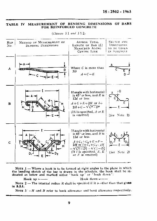
TABLE IV MEASUREMENT OF BENDING DIMENSIONS OF BARS FOR REINFORCED CONCRETE
RF-F No.
C
-
_ -
_ -
_ -
-
METHOD OF MEASUREMENT OF EMENDING DIMENSIONS
.%PPROX TOTAL LENGTH OF BAR (L)
XEASUBED AL0h.c;
ChNTRE LINE
Where C is more than 30
A+C+E
If angle with horizontal is 45” or less, and R is 12d or less
A+C+E+2H or I+ ___ ZH+C--d/C’--U’
(If I is specified, A or E is omitted)
If angle with horizontal is 45” or less, and R is 12d or less
d -t_C,+Cy+L:+f~i- 2H or l+C1+CI-, iH --
-d/cl -0; -l/c; -0; (If 1 is specilietl, A, E
or I; is omitted)
-
NOTE .l -Where a hook is to be formed at right angles to the plane in which the bending sketch of the bar is drawn in the schedule. the hook shall be in- dicated as below and marked either ‘ hook up ’ or ’ hook down ’ :
Hook up L- Hook duwn ---
NOTE 2 - The internal redius H shall 1~ specitivd if it is other than that givrrn in 3.2.1.
NOTE 3 -H and B rcfcr to hook ;rll~~w.mcc ;tnd I)cnd allow;tncc respccti’velp.
Y

IS:2502- 1963
TABLE V MEASUREMENT OF BENDING DIMENSIONS OF BARS FOR REINFORCED CONCRETE
(Clauses 3.1 and 3.1.2) __. REF. NO.
A
-__---- METHOD OF ML~CXREMETT
0~ BENDIXG D~WXNSIONS
I-- A L R
E-4 - 8 T- A L L R 7
6 I
k---4
APPROX TOTAL LENGTH OF 13~~ (L) MEASUREL
A~ONGCENTRELINE
.4 +E--)R--d
.4 +E---3R-d+2B
A -j-E--+R-d+2H
--____ SKETCH AND nIWiNSIONS TO BE <;IVEK IN SWEDULE
A I E
( See Notes .2 and 3 )
E
(See Notes 2 and 3)
A c R
E
(See Notes 2 and 3)

IS:2502 - 1963
TABLE VI MEASUREMENT OF BENDING DIMENSIONS OF BARS FOR REINFORCED CONCRETE
(Claurs 3.1 nnd 3.1.2)
HEE
X0.
A
--
B
c
D
E
-
\IETHOD 0~hlE~s~R~~xi~w
OF BENDING DIMENSIOSS
i! TL A & cl H
r--E
A+E+lfD+2H
’ If angle with horizontal is45” / I or. less
/ I
I A+E
i- --
If angle with horizontal is 45’ or less and H is 12d or less
-4 J-E+2H
I1 angle is greater thau 45” and R exceeds 12d, L to be calculated
If angle with horizontal is 45” or less
A+B+C-I-H--Z(R+d)
If angle is greater than 45” and R exceeds 12d, L to be calculated
1-k2H
-
(See Note 2)
t (See Note 2)
hrorr 1 -Whew a hook ib to be lormrd at right angles to thr plane in which the bending sketch of N is drawn in thv schrdulr, the hook shall be indicated ax below and marked either ‘ book up’ or ’ Book down ’ :
Hwk up a--- Hook down _-- No’& :! - The internal radius R shall be specified if it is other than that given in 3.2.1. NOTE 3 - H and B refer to hook allowa~w and bend allowance respectwely. NOTE 4 - Dimensions X and Y should be practical dimensions to enable the angle of the bend to be
determined.
11

-.
IS:2502 - 1963
TABLE VII MEASUREMENT OF BENDING DIMENSIONS OF BARS FOR REINFORCED CONCRETE
REP NO.
A
B
C
D
B
P
7
! -1
--
_ -
_
I’
A+E+!LS+ZH+d
A+E+SS+Pd+BtH
AtEtCtZH-d/Cm-D
ItZCtPH
-r S E
A
( See Notes 1 nncl 2 )
A
% E S-J
-I
( Srr Notes 1 and 2)
(Str Note 1 )
(Set Note 1)
(.S# Note 1 )
Nohl- The internnl nulior H shnll he specified if It is other than that giyen in &%I.
Non 2- H, B and 4 rrfrr to hook aUowsncc, bend allowance and 8 nominal sire of bar rmpwtively.
12

IS : 2502 - 1963
TABLE VIII MEASUREMENT OF BENDING DIMBNSIONS FOR BINDERS, STIRRUPS, LINKS AND TRE LIKB FOR REINFORCED CONCRETE
(c&urcr 3.1 card 3.1.2)
“N”,9
A
_-
B
C
- - APPROX TOTAL LENGTH of BAR (L) Measuaen ALONG
cmrae LINE
METHOD OP MEASUREMENT OP BENDING DIMENSION
(See Notes 1 and 8)
2(A+E)+24d
cl A E 2(‘4+q+w
(Sss Notes 1 and 2)
-i- _ _
. -
0 A E 2A+E+PBd
2AtEtCtl2dtB
(Su Notes 1 and 8) . -
C
13 A E
D
/I - [Sar Notes 1 and 8)
C
73 A E
E
(Se-s Notes 1 and 8) _I-
(See Notes 1 and 3)
&E--l (.%a Notes 1 and 8)
1 -The inturnal radius R of th~corne.rn of binders, stlrmps, etc, shall be specified If it is other t given in am. I - If the form of the b&r is such that there ma be doubt as to which is the inside of the ws should be shown on the bending schedule an fr the dimension stated with the sutfir OD or de or inside dimoneion). 1 -B and d refer *o bend allowance snd’nominal sirs of bar rospectivdy.
13

IS : 2502 - 1963
TABLE IX MEASUREMENT OF BENDING DIMENSIONS FOR BINDERS, STIRRUPS, LINKS AND THE LIKE FOR
REINFORCED CONCCETE
REF No.
A
METHOD OF 1hfEASUREMENT OF
BENDING DIMENSION’
lt!Ll A
D
B / :xE A
D
T
S'
-I -
_i _
j
_’ -
C
a D
APPROX ‘TOTAL LENGTH OF RAR (.C.) MEASURED
ALONG CENTRE LINE
2A+3D+22d
2.4 + 3 D + 22d
Where P is not greater than D/S
Nx (D+d)+lki N =I number of complete and
fractional turns D = internal dia P = pitch of helix d = size of bar
--
(Ciauses 3.1 and 3.1.2)
NOTE -d refers to nominal size of bar.
7
_
-
SKETCH AND DIMENSIONS
‘IO BE GIVEN IN SCHEDULE
8
A D
(See Note)
-
-
n A D
(Seu Note)
14

IS : 2502 - 1963
TABLE X BARS BENT TO A RADIUS
(Cluuse 4.1)
NOMINAL CRITICAL SIZS RADIUS
mm m
: ;:; 10 3.5 12 5.0 :i 12.0 8.0
:: 24.0 18:O
34.0 40.0
TABLE XI PERMISSIBLE BENDING AND CUTTING TOLERANCES
(Cla14.w 5.1)
DIMENSION r--_-------h--__? Over Up to and
Including
Tar ERANCE (_..--h -----l
Plus Minus
cm cm mm mm
For Bend Bars 75 75 3 150 2
1: 150 250 250 - 7 ::
For Straight Bars All lengths 25 25
5.1.2 The cutting tolerance for bars to be bent shall be the tolerance given for straight bars. To allow for this cutting tolerance when dimen- sioning bent bars, at least one dimension shall not be specified.
6. BENDING
6.1 General - Bars shall be bent cold except as provided in .6.1.1. Any type of equipment may be used for bending of bars with the prior approval of the engineer in-charge.
15

IS : 2502 - 1963
6.1.1 Bars larger than 25 mm in size may be bent hot at cherrv-red heat (not exceeding SSOT) except those t#+rs which depend for their strength on cold working. Hot bars shall not’be cooled by quenching.
6.2 Equipment -- Bending of bars may be done either by improvised means or by hand-operated machines (set Fig. 2, 3 and 4), and by power- operated bender. For bars of 12 mm diameter and untlcr, mechanical contrivances of the type illustrated in Fig. 2 may be advantageously employed.
\ \MANDREL
STOP
FIG. 2 BENDING OF BAR BY MEANS OF CLAW
SOCKET- /- HOLE
L MANDREL
FIG. 3 SIMPLE BAR-BBNDING MACHINE
16
IS : 2502 - 1963
RATCHET LEVER
MANDREL PLAIN ROLLER
L GROOVED ROLLER
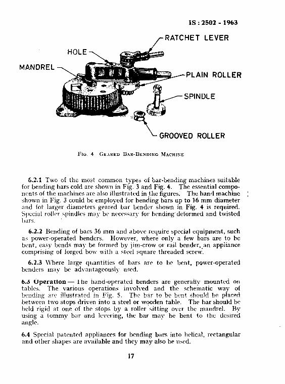
FIG. 4 GE.IRED BAR-BENDIKG ~IACHINE
6.2.1 Two of the most common types of bar-bending machines suitable for bending bars cold arc shown in Fig. 3 and Fig. 4. The essential compo- nents of the machines are also illustrated in the figures. The hand machine I shown in Fig. 3 could be employed for bending bars up to 16 mm diameter and fok larger diameters geared bar bender shown in Fig. 4 is required. Special roller spindles may be necessary for bending-deformed and twisted bars.
6.2.2 Bending of bars 36 mm and above require special equipment, such as power-operated benders. However, where only a few bars are to be bent, easy bends may be formed by jim-crow or rail bender,_an appiiance comprising of forged bow with a steel square threaded screw.
6.2.3 \Vhere large quantities of bars are to bc bent, power-operated benders may be advantageously used.
6.3 Operation - The hand-operated benders are generally mounted on tables. The various operations involved and the schematic way of bending are illustrated in Fig. 5. The bar to be bent should be placed between two stops driven into a steel or wooden table. The bar should be held rigid at one of the stops by a roller sitting over the mandrel. By using a tommy bar and levering, the b<ar may be bent to the desired angle.
6.4 Special patented appliances for bending bars into helical, rectangular and other shapes are available and they may also be used.
17

Z$ : 2502 - 1963
BODY OF MACHINE
CENTRE OF BAR TO START OF BEND
/STRAIGHT EDGE
‘iv TO OBTAIN ANY DEPTH OF SET PLACE BAR TOUCHING STOP AND MANDREL. MEASURE THE REQUIRED .DlSTANCE FROM A TO B
TO OBTAIN DESIRED DISTANCE FROM BEND C TO INSIDE ‘OF HOOK D, MEASURE FROM OPEN SET C TO FAR SIDE OF MANDREL D. FOR OVERALL MEASUREMENT ADD THICKNESS OF BAR
BENT BAR
FIG. j BENDING OF BAR
7. FIXING REINFORCEMENT
7.1 General -- The economy of reinforced concrete design will be fully realized only when the reinforcements are maintained at their designed
1s : 2502 - 1963
positions at all times. The important factors in fixing the reinforcement are precision and convenience.
7.1.1 Reinforcement shall be placed in position as given on the detailed design drawing and shall be secured at that position. In case of delay occurring between fixing of reinforcement and concreting, the position of the reinforcement shall be checked priot to concreting.
7.1.2 Lapping of bars shall be done\ in accordande with the relevant requirements specified in IS: 456-1964 Code of Practice for Plain and Reinforced Concrete (Second Hevisim). Laps shall be staggered.
7.1.3 The precautions described in 7.2 to 7.5 shall be taken to plcvent displacement of reinforcement during shuttering and concreting.
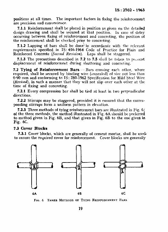
7.2 Tying of Reinforcement Bars - Bars crossing each other, where required, shall be secured by binding wire (annealed) of size nqt less than 0.90 mm and conforming to IS: 280-1962 Specification for Mild Steel Wire (Revised), in such a manner that they will not slip over each other at tfie time of fixing and concreting.
7.2.1 Every compression bar shall be tied at least in two perpendicular directions.
7.2.2 Stirrups may be staggered, provided it is ensured that the corres- ponding stirrups form a uniform pattern in elevation.
7.2.3 Three methods of tying reinforcement bars are illustrated in Fig. 6: of the three methods, the method illustrated in Fig. 6A should be preferred to method given in Fig. 6B, and that given in Fig. 6B to the one gived in Fig. 6C.
7.3 Cover Blocks
7.3.1 Cover blocks, which are generally of cement mortar, shall be use& to ensure the’required cover for reinforcement. Cover blocks are generally
6A 68 bC
FIG. 6 THREE METHODS OF TYING REINFORCE~~ENT BARS
19
IS:2502 -1963
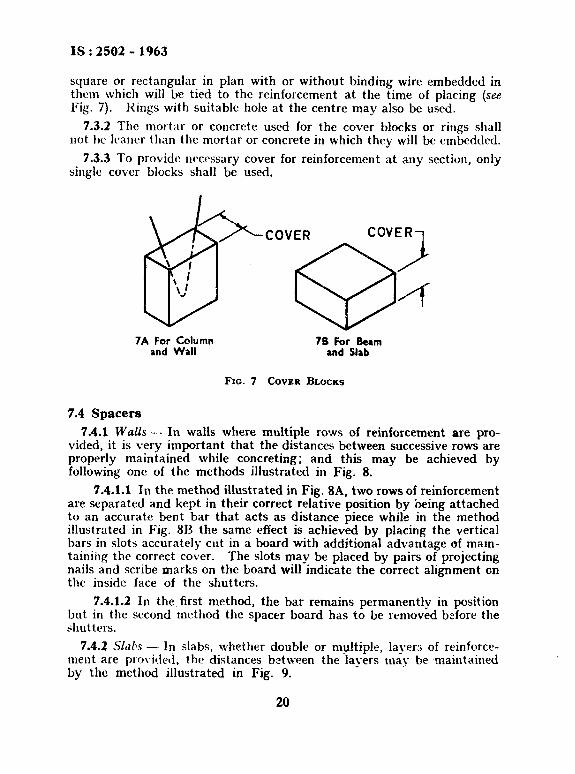
square or rectangular in plan with or without binding wire embedded in them which will be tied to the reinforcement at the time of placing (see Fig. 7). Kings with suitable hole at the centre may also be used.
7.3.2 The mortar or concrete used for the cover blocks or rings shall not be lcaner than the mortar or concrete in which they will be embedded.
7.3.3 To provide necessary cover for reinforcement at any section, only single cover blocks shall be used.
COVER COVER
i
4
7A For Column 78 For Beam and Wall and Slab
FIG. 7 COVER BLOCKS
7.4 Spacers
7.4.1 W&s - In walls where multiple rows of reinforcement are pro- vided, it is very important that the distances between successive rows are properly maintained while concreting; and this may be achieved by following one of the methods illustrated in Fig. 8.
7.4.1.1 In the method illustrated in Fig. 8A, two rows of reinforcement are separated and kept in their correct relative position by being attached to an accurate bent bar that acts as distance piece while in the method illustrated in Fig. 8R the same effect is achieved by placing the vertical bars in slots accurately cut in a board with additional advantage of mam- tainihg the correct cover. The slots mav be placed by pairs of projecting nails and scribe marks on the board will-indicate the correct alignment on the inside face of the shutters.
7.4.1.2 In the first method, the bar remains permanently in position but in the second method the spacer board has to be removed before the shutters.
7.4.2 SL&s - In slabs, whether double or multiple, layers of reinforce- ment are provided, the distances between the layers may be maintained by the method illustrated in Fig. 9.
20

L. ..“. ..--
IS : 2502 - 1963
7.4.2.1 In the figure, additional support bars are shown inserted; but in a good design, the provision of these extra bars would not be necessary as the designer would so arrange the reinforcement that the supporting bars would bc a part of the principal reinforcement.
ACCURATELY BENT SPACER BAR WIRED TO VERTICAL OR HORIZONTAL BARS
COVER BLOCK
IDTH OF WALL
BA USE OF WALL SPACER BAR
SCRIBE MARK SPACER BOA
ACER BOARD NAILED ROSS TOP OF FORMS OTS ACCURATELY CUT
[HORIZONTAL AND VERTICAL BARS WIRED AT EACH INTERSECTION
88 USE OF SPACER BOARD
FIG. 8 MAINTAINING WALL BARS IN Posmos
,
21

IS : 2502 - 1963
SLAB REINFORCEMENT TOP LAYER
THIS DIMENSION TO BE ACCURATE
L CENTERING OR GROUND
L SUPPORT BARS
COVER BLOCK
v SCAB REINFORCEMENT BOTTOM LAVER
FIG. 9 DOL'BLY REINFORCED SLAB
7.4.3 Beams - In beams with top reinforcement, it is desirable to suspend the top reinforcement from the formwork by suitable arrangements which may be removed on completion of concreting up to the appropriate i level, unless such reinforcement is otherwise rigidly held in position by stirrups or other members.
7.5 Column . Reinforcement - The column reinforcement, especially in heavily reinforced columns and in columns subjected to a combination of direct load and bending, should be properly tied, otherwise the strength of the column will be considerably affected. Some of the typical methods of tying the reinforcement are shown in Fig. 10. The ties may. be staggered provided it is ensured that the corresponding ties form a uniform pattern in elevation and they shall be in closed loops.
.1.6 Distortion of projecting vertical bars in double rows in walls may be prevented prior to completed assembly of horizontal reinforcement and erection of shutters by the arrangements illustrated in Fig. 11. This arrangement consists of a longitudinal timber or large bar placed along each row of vertical bar and tied to each bar. Between every sixth bar of opposite rows a cross piece of wood or steel should be tied.
7.6.1 For single vertical row of large bars in walls, a timber frame as illustrated in Fig. 12 may be employed to prevent the distortion of bar. The dimensions, details and spacing of the frame shall be determined by the nature of the work.
NOTE - The frame could often be part of the shuttering.
22

4 BARS SINGLE TIES
l0 BARS 3 TIES PER SET
6 EARS 2 TIES
PER SET
12 BARS 3 TIES PER SET
18 BARS 6 TIES PER SET
8 BARS 2 TIES
PER SET
14 BARS 4 TES
PER SET
20 BARS !i TIES
PER SET
TYPICAL SECTIONS OF GENERAL PURPOSE COLUMNS
CoLuuN STEEL ALTERNATE METHOO TYPICAL ARRANGE -
ARRANGED FOR Of TIE ARRANGEMENT MEN1 OF CORNER
amJolNo AWO fOR ELOWATEO COLUMNS
OrnCf STRESS COLUMNS
TYPICAL SECTIONS OF SPECIAL PURPOSE COLUMNS
Nom 1 - If access to the interior of a column is necessary, a different pattern of ties may be substituted provided ties are so designed that each vertical bar is ro;el; braced ajlainst movement.
--The tieb may be staggered provided it is ensured that the corres- pending ties form a uniform pattern in the elevation.
FIG. 10 COLUMN TIES
23

IS : 2502 - 1963
TEMPORARV IMBER WIRED 0 OCCASIONAL
BARS
L COkCRETE ALREADM IN POSITlOt
FIG. 11 STIFFENING OF PROJECTING VERTICAL
8. TRANSPORTING REINFORCEMENT
8.1 Reinforcement shall be transported to the
Wat.L REINFORCEMENT
site of work or to the place of storage by such means and in such a manner that the reinforcement is neither damaged nor deformed. The unloading of the reinforcement shall be done at the nearest convenient place where it is to be processed further. Particularly in cases ~hcre unloading is required to be done by hand, it is important thxt the vehicle should be brought as close as possible to the stacking or bending place in order to avoid carrying over long distances. As far as posGble, at the time of unloading the bars should be separated by sizes and lengths.
9. STORAGE OF- REINFORCEMENT
9.1 The aetula;l location of the stacking place of reinforcement depends upon the site conditions, but it should be such that the reinforcement could he con\xxiently rcccivcd and supplied to the operational centres in the site. On works covering large area;, it might be an advantage to stack the
24

. ._ -- ,. I-
IS:2502 -1963
/- BAR WIRED TO FRAME AN0 EACH VERTICAL BAR
TEMPORARV
FRAMEWORK
TWO SERIES OF
L VE RTICAL BARS BOTTOM SLAB WIRED TOGETHER
COtiCRETED WITH BARS PROJECTING
FIG. 12 SUPPORTING VERTJCAL WALL REINFORCEMENT
reinforcement at diffcrcnt plnccs close to the areas where they arc likely to bc used most.
9.1.1 In order to ensure that the reinforcement bars are kept in good condition, they should not be left in direct contact with the ground but they should be stacked on top of an arrangement of timber sleepers or the like. Suitable racks may also be used for stacking reinforcement in tiers. Where space is extremely limited, bars may also be stacked vertically but the vertical stacking has the disadvantage that it is more difficult to get the bars in and out and in identifying bars of different sizes and lengths. Whatever method of stacking is adopted, the bars should be stacked in
25

IS:2602-1963
such a way that the various sizes and lengths can be quickly and easily identified.
9.1.2 After the reinforcement bars have been bent, they should be placed in the most convenient locations for trans Flexible bends like stirrups and bends of small ~ 8”
rt to working points. iameter bars should be
grouped together and bundled for ease of handling. Each bundle of bars or group of bars should have labels affixed to it indicating the bar mark, bending schedule reference number and its position in laying.
9.1.3 In storing bars, attention shall be paid to avoiding distortion and to preventing deterioration and corrosion.
9.1.4 Whilst a certain amount of hard rust on the reinforcement is con- sidered desirable in reinforced concrete work, care should be taken to ensure that undue rusting or loose scaling do not take place in storage and in such conditions of weather where the reinforcement is likely to get corroded, the stack of reinforcement shall be suitably sheltered.
26

BUREAU OF INDIAN STANDARDS
Headquarters Manak Bhavan, 9 Bahadur Shah Zafar Marg, NEW DELHI 110002 Telephones: 323 0131,323 3375,323 9402 Fax : 91 11 3234062, 91 11 3239399, 91 11 3239382
Central Laboratory :
Plot No. 20/9, Site IV, Sahibabad Industrial Area, Sahibabad 201010
Regional Otfkee:
Telegrams : Manaksanstha (Common to all Offices)
Telephone
8-77 00 32
Central : Manak Bhavan, 9 Bahadur Shah Zafar Marg, NEW DELHI 110002 32376 17
*Eastern : l/l 4 CIT Scheme VII M, V.I.P. Road, Maniktola, CALCUTTA 700054 337 86 62
Northern : SC0 335-336, Sector 34-A, CHANDIGARH 160022 60 38 43
Southern : C.I.T. Campus, IV Cross Road, CHENNAI 600113 23523 15
twestern : Manakalaya, E9, Behind Marol Telephone Exchange, Andheri (East), 832 92 95 MUMBAI 400093
Branch Offices::
‘Pushpak’, Nurmohamed Shaikh Marg, Khanpur, AHMEDABAD 380001
SPeenya Industrial Area, 1 st Stage, Bangalore-Tumkur Road, BANGALORE 560058
550 13 48
839 49 55
Gangotri Complex, 5th Floor, Bhadbhada Road, T.T. Nagar, BHOPAL 462003 55 40 21
Plot No. 62-63, Unit VI, Ganga Nagar, BHUBANESHWAR 751001 40 36 27
Kalaikathir Buildings, 670 Avinashi Road, COIMBATORE 641037 21 01 41
Plot No. 43, Sector 16 A, Mathura Road, FARIDABAD 121001 8-28 88 01
Savitri Complex, 116 G.T. Road, GHAZIABAD 201001 8-71 1996
53/S Ward No.29, R.G. Barua Road, 5th By-lane, GUWAHATI 781003 541137
B-8-56C, L.N. Gupta Marg, Nampafly Station Road, HYDERABAD 500001 201083
E-52, Chitaranjan Marg, C- Scheme, JAIPUR 302001 37 29 25
117/418 B, Sarvodaya Nagar, KANPUR 208005 21 68 76
Seth Bhawan, 2nd Floor, Behind Leela Cinema, Naval Kishore Road, 23 89 23 LUCKNOW 226001
NIT Building, Second Floor, Gokulpat Market, NAGPUR 440010 52 51 71
Patfiputra Industrial Estate, PATNA 890013 26 23 05
Institution of Engineers (India) Building 1332 Shivaji Nagar, PUNE 411005 32 36 35
T.C. No. 14/l 421, University P. 0. Palayem, THIRUVANANTHAPURAM 696034 621 17
*Sales Dffice is at 5 Chowringhee Approach, P.O. Princep Street, CALCUTTA 700072
271085
tSafes Dfffce is at Novefty Ch.ambers, Grant Road, MUMBAI 409007
*Safes office is at ‘F’ Block, Unity Building, Narashimaraja Square, BANGALORE 560002
3096528
222 3971
Reprography Unft, BIS, New Delhi, India